birthday drone - zachary blum · birthday drone final report - me271e luke asperger, tatiana mowry,...
TRANSCRIPT

Birthday Drone
Final report - ME271E
Luke Asperger, Tatiana Mowry, Coline Nantermoz, Zach Blum
1
Table of contents
Executive Summary 3
Renders in different configurations 3
Summary of Performance Specifications 4
Summary of the mission 4
Summary of the scaled delivery demo 4
Mission 5
Systems Engineering 8
Project Objective Statement 8
Mission Need Statement 8
Functional Flow Diagram 8
Functional Breakdown Structure 9
Requirements Discovery Tree 10
Work Flow Diagram 11
Work Breakdown Structure 11
Gantt Chart 11
Hazard Analysis Write-up (SHARP) 12
Configuration 15
Four Designs 15
Selecting Final Configuration 17
Robot Constraints 18
Sizing Optimization 18
Description of final configuration 18
Critical Performance Specs 19
Wing design in XFLR5 20
Wing geometry 20
Elevator and fin geometry 20
Results 21
Delivery mechanism design 23
Demo 25
Mission and Waypoints 25
Actuators’ control 26
PID tuning 26
Screengrabs 26
Final Design 28
3 View Drawings with dimensions (in inches) 28
Renders of hybrid aerial robot in different flight configurations 29

2
Delivery Mechanism 30
Sized and selected components 33
Performance Specifications 34
Future Directions 36
3
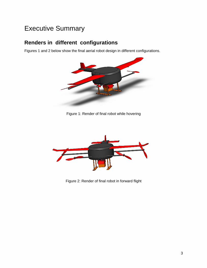
Executive Summary
Renders in different configurations
Figures 1 and 2 below show the final aerial robot design in different configurations.
Figure 1: Render of final robot while hovering
Figure 2: Render of final robot in forward flight

4
Summary of Performance Specifications
Figure 3: Chart of Key Robot Parameters
Summary of the mission
Our project’s mission was to safely deliver a birthday cupcake onto an empty table at a specified
time, because it would be a valuable addition to a special occasion.
Summary of the scaled delivery demo
In order to test our delivery mechanism, we attached it to the bottom of our quadcopter.
At Stanford’s Lake Lagunita, we manually piloted the drone off of the ground to a hover, then
had the autopilot fly the drone to selected waypoints in a relatively square path. Once it returned
to the starting location, we switched to manual flight to land the drone, released the package by
activating the delivery mechanism, and finally took off and landed at the takeoff site.

5
Mission
In the beginning of the project, we started with four main ideas about potential missions.
The first idea was to design a drone that would be capable of safely transporting and delivering
a fragile item made out of glass, by minimizing sudden motion and orientation changes during
transport. The second idea was to deliver a food item at a precise, predetermined time and
location. The third idea was to increase ease of assembly for products made up of multiple
parts, by having the drone lay each individual part of an assembly in a location convenient for
assembly. The fourth idea was, in order to reduce the need for human action, we would design
an aerial robot capable of identifying a predetermined package from a row of boxes and
autonomously picking it up for delivery.
In order to select which mission idea to pursue, we constructed a tradeoff chart, shown
below in Figure 4.
Figure 4: Tradeoff Chart for Mission Ideation
The items in the leftmost column of the chart represent depictions of the mission ideas
discussed above: identifying one out of many packages, carrying fragile items, delivering food,
and aiding in assembly. The top row represents the criteria used to judge each of these ideas.
The box highlighted in blue--time needed--represents the criterion with highest weight, and
signifies the time needed to actually construct a drone and delivery mechanism capable of
performing the given task. The other criteria represent complexity of the mission idea,
probability of us succeeding in building a working drone to perform the given task, cost of the
materials needed to build the mechanism for the drone, utility of the mission, how “cool” the
mission seemed to us, and if the mission was safe to perform. After ranking the ideas on each
of the categories (from 1 to 3, with 1 being bad at the given criterion and 3 being great), the idea
that succeeded (highlighted in red) was delivering food, at a precise, predetermined time and
location.

6
After we had narrowed down the mission to the delivery of food, we further ideated to
decide what food item we wanted to deliver. While the initial idea had been to deliver a box of
pizza, we all very much enjoyed the idea of delivering a birthday cake/cupcake as a surprise on
someone’s birthday, because the delivery would not only be useful in that it would provide the
guests of a party with food, but also because it would be an enjoyable surprise addition to the
party. Ultimately, we decided on the following as our overall mission: our project’s mission was
to safely deliver a birthday cupcake onto an empty table at a specified time, because it would be
a valuable addition to a special occasion.
After specifying our mission statement, we then needed to devise a delivery scenario in
which our delivery would be useful and appropriate. We envisioned Stanford students
celebrating a birthday on Meyer Green on Stanford’s campus, and one of the guests would like
to surprise the person whose birthday it is with a cupcake. The student wants to get the
cupcake delivered from Sprinkles in the Stanford Shopping Center. Because the streets
between Stanford Shopping Center and Meyer Green are congested, and the student would like
to add an element of surprise to the party, the student requests in advance that the cupcake be
delivered by drone at a specific time. Taking this as an example use case, we then needed to
determine appropriate takeoff and landing locations. Because Meyer Green is already a
relatively open space with tables, we kept this as our landing location. We then looked and
found that there was an open plaza behind Sprinkles in the shopping center, which would serve
as an acceptable takeoff location. The sample takeoff and landing locations are shown below in
Figure 5a and Figure 5b.
Figure 5a: Takeoff location in plaza behind
Sprinkles in Stanford Shopping Center.
Figure 5b: Landing location on Meyer Green
Because there are no major obstacles in this path from Sprinkles to Meyer Green, we
determined that the optimal path would be to simply fly straight from Sprinkles to Meyer Green,
at its cruise altitude of between 50 and 100 feet. This path is about 1.14 miles one-way. This
delivery scenario path is shown below in Figure 6.

7
Figure 6: Sample delivery scenario flight path from Sprinkles to Meyer Green.

8
Systems Engineering
Project Objective Statement
The goal of the project objective statement is to clarify what the project is about, and to
balance resources, time and result considerations. Our project objective statement is:
“Surprise someone on their birthday by delivering a cupcake using a drone at the specified time,
using commercially available off-the-shelf components in 7 weeks.”
Mission Need Statement
The Mission Need Statement is a concise description of the functions that the project’s
result will have to perform. It is intended as a reference throughout the project. Our Mission
Need Statement is:
“Safely deliver a birthday cake onto an empty table at a specified time.”
It highlights our deliverable: an aerial robot capable of delivering a cupcake, the required
performance: we are focusing on delivering at a precise time and location, and the main
constraint: security, both of the user(s) and of the cupcake (it shouldn’t be damaged).
Functional Flow Diagram

9
In summary, before the mission begins, we will receive the order and calculate the
logistics for completing the mission. After inspecting the robot to ensure it is ready for takeoff, it
will launch and fly to the destination. The drone will place the cake on a table and play the
happy birthday song. Then, it will takeoff, and fly back to base and land there.
Functional Breakdown Structure

10
In summary, performing the mission will consist of four main functions. The drone will be
provided power which will be distributed and regulated throughout the flight. In performing the
flight, the rotors and wings will provide propulsion and lift, and we will monitor the payload and
use controls to ensure that the drone remains stable. In order to provide guidance and
navigation, we will calculate the route and time needed to complete a certain delivery, and
Mission Planner will aid in autonomously flying to the desired location. The delivery will use an
actuator to release the cake onto the table, and will confirm the delivery before taking off again.
Requirements Discovery Tree
There
are two main branches of our Requirements Discovery Tree: performing the mission technically
and performing the mission with constraints. Performing the mission technically will require a
combination of providing power to guide and navigate during the flight, and actually delivering
the cake. In performing the mission with constraints, we deal with development constraints
(such as the timeframe and risk of the project) and constraints on the design (including weight,
wingspan, speed, and hover time).
11
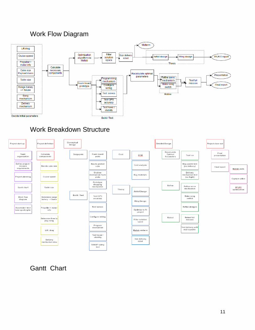
Work Flow Diagram
Work Breakdown Structure
Gantt Chart

12
Hazard Analysis Write-up (SHARP)
The main hazards were from flying objects, the fast propellers, and the LiPo batteries.
To mitigate risks, we performed a short trial run before our Lake Lag flight by carefully stepping
through our mission steps. We discussed where to land and release the box and one team
member held the robot and carried it through the mission as a dry run. We also took precautions
to make sure no one would be hurt: we stored our batteries carefully, we used the arming
system and a safety switch on the robot, and we ensured that the drone would not be too close
to others
During the actual mission, the robot ran out of battery and fell to the ground. Fortunately,
this was a hazard that we had forseen and no one was near the robot when it fell. To identify

13
even more hazards in the mission, we could perform more trial runs to see if they are
consistent. We could also talk to other teams to learn about any problems they encountered.
Section A : Identify the general hazards
Hazard Conditions or Processes:
- Moving equipment / parts
- Electrical
- Heat / hot surfaces
- Needles / sharps
- Falling objects
Section B: Outline the Procedure
Sequence of Steps and Tasks
Hazard Hazard Control Measures
Gather stuff to take to Coyote Hill
Battery should be in pouch Checklist: safety glasses, fire extinguisher, water, sunscreen, drone and controller, charged batteries
Load the payload on the drone Check the CoM
Battery should not be connected, but attached to the top of the drone
Connect the battery. Push the safety button
After this step, everyone should be behind the pilot
Arm the motors Propellers turning Make sure no one else is flying. Tell the other groups we’re arming
Take off in manual mode Watch the stability at low altitude, land if it’s too wobbly
Put in autopilot mode Make sure it is far away enough
Test the delivery mechanism: land / drop payload
Take off and return without payload
Check the PID constants
Land back at start Make sure everyone is out of the way

14
Summary of PPE:
- Appropriate street clothing (long pants, closed-toed shoes..)
- Safety glasses
Section C: Question your methods
What if the payload wobbles too much?Then switch to manual mode and tweak the PID
constants
Risk rating: it is likely but no injuries / minor (if the payload actually detaches and falls) →
medium
What if we lose sight of the quadcopter? Then, land the quad wherever it is, locate it on Mission
Planner and pick it up. Don’t forget to bring the fire extinguisher
Risk rating: it is possible but minor, and a risk of fire is really rare but would be moderate to life
impacting → medium
What if a bird comes close to the quadcopter? Then land
Risk rating: rare and minor → low
Everything is in the low - medium range → we just have to ensure we are following best
practices.
Section D: Perform a trial run
Try delivery mechanism separately: lab checkoff this week
Try to fly quadcopter separately indoors / outdoors: already done
Fly indoor with manual control: next week lab checkoff
Fly outdoor and land on a table top / target: final goal

15
Configuration
Four Designs
Tilt Rotor Design: This design consisted of 4 propellers arranged in a trapezoidal shape. The
propeller motors are attached to rods that can rotate via stepper motors in the body of the robot.
Weighing in at 5.42 kg with a wingspan of 1.2 meters, this configuration can achieve a range of
46.0 km.
Multi-Rotor Design: This configuration was designed to work well in forward flight as well as
hover. It could take advantage of an existing quadcopter base for the hover rotors and the
cruise rotors would activate for forward flight. It achieved a range of around 60 km.
Plane Design: This design maximizes range, and ends up with a final range of 96km. That’s
why it has many rotors for forward flight, and is very light (the cupcake(s) are kept in the bay,
which would open thanks to a trap door). We named it the plane design because it is very
aerodynamic, however, the vertical takeoff and landing would consume a lot of battery.

16
Tilt Body Design: This design includes four propellers along the wings, and the body tilts in
order to transition between hover and cruise. The final total mass for this design was 2.8365 kg,
with a wingspan of 1.17m. This configuration achieved a maximum range of about 38.1km.

17
Selecting Final Configuration
Criteria
Configuration Payload Safety (25)
Material Cost (20)
Range (10)
Aesthetics (10)
Delivery Feasibility (20)
Design Simplicity (15)
Tilt body 1 3 2 3 3 3
Tilt rotor 3 2 2 3 3 2
Multi-rotor 3 1 3 3 3 2
Plane 3 1 3 3 2 2
There were a number of factors we considered when selecting our configuration. The
most important consideration was payload security. Because we are delivering a cupcake, we
needed a design that would minimize changes in orientation, which was something that the tilt
body would not be able to do well.
Additionally, we needed to keep the material cost down and the design complexity down
because delivering a cupcake is not a task that you can easily justify an overly expensive robot
for. The added motor and propeller costs were major downsides to the multi-rotor and plane
designs. The mechanism for tilting the rotors is fairly straightforward, so we believed the tilt rotor
design would be both relatively cheap and feasible from a design perspective.

18
Robot Constraints
One of the biggest constraints that the tilt-rotor design puts specifically on the robot is on
the length of the body. We needed to make sure that there would be room for the propellers to
rotate without interfering with the wings of the robot. An exact check of this constraint would
have required calculating angles and comparing the the three dimensional geometry of the
body. However, we were able to come up with a much simpler and sufficiently accurate check
that only looked at the body length and made sure it was at least as great as twice the propellor
diameter plus the chord length.
𝑏
𝐴𝑅+ 𝑑𝑝𝑟𝑜𝑝 ≤ 𝑙𝑏𝑜𝑑𝑦
The second constraint we threw in was that the wingspan had to be less than 1.2 meters. This
was because we wanted to make sure that it would be able to fit on a standard sized picnic
table when delivering a cupcake.
Sizing Optimization
The constraints enumerated above were added to the matlab optimization, so all the designs
MATLAB gave us fit within those constraints. The parameters we optimized for were cruise
velocity, wingspan, aspect ratio, taper ratio, and propeller diameter. The goal of our optimization
was range, as this will allow us to deliver the cupcake from locations as far as possible.
Description of final configuration
The final configuration of our robot is a tilt-rotor design similar to the design in the foam board
prototype shown below. The propellers are arranged in a trapezoidal geometry to minimize air
flow disturbance between the propellers during forward flight. The propellers are fixed to axels
that rotate via servo motors in the body of the plane.
The exact propeller placement could be optimized further. However, that is beyond the scope of
this class. The wingspan is 1.2 meters, as specified by the sizing optimization. In this prototype,
the body is simple shaped as a rectangular prism using the length, width, and height
measurements spit out by MATLAB, but further optimization would yield a more aerodynamic
body.

19
Critical Performance Specs
A full chart of our performance specifications is located at the end of our report. However, a few
key highlights of the parameters spit out by our MATLAB optimization are listed in the following
chart.
Parameter Final Value
Total Mass 5.42kg
Battery Mass Fraction 0.61
Body Length 0.39m
Body Width 0.31m
Body Height 0.15m
Cruise Velocity 20m/s
Range 46km
Propeller Diameter .22m
Taper Ratio .8
Wingspan 1.2m
Aspect Ratio 7.5

20
Wing design in XFLR5
Wing geometry
Wingspan Area MAC Aspect ratio Taper ratio Root to tip sweep
1.2 m 0.2 m2 0.167 7.31 0.68 5.71o
We used NACA 23012 airfoils. At first, we wanted to use high performance, low Re, high
lift airfoils, comparable to the ones found on sailplanes, but, as those airfoils were very
cambered, the pitching moment was always negative. Thus, we got back to the conventional
NACA 23012. To make it stable (negative slope of Cm), we had to tweak the center of gravity of
the plane. This corresponds to what happens in reality as well: our delivery mechanism +
cupcake is heavy (200g) so its position (and the one of the battery) determine the position of the
center of gravity. Flying with a badly positioned CG leads to inevitable crashes, as we
experienced during indoors flying tests.
We also added twist to prevent stalling at the tips.
Elevator and fin geometry

21
Results
To Have a pitching moment Cm of 0, we choose an angle of attack 𝞪 = 11.0o. This results in a
CL of 1.14, comparable with the one we obtained in the midterm (1.13).

22
The CL/CD ratio of 13.8 is not optimal but stays quite good, and brings us enough lift.
xCG = 0.094m ; xNP = 0.11m ; MACwing = 0.167m → SM = 10%. Our plane is really stable to
disturbances in pitch.
The lift profile at 𝞪 = 11.0o is given by:
We reran the midterm analysis using the polars from NACA23012 instead of 23112 and the right
Reynolds number and we got slightly more range with a slightly higher lift.

23
Delivery mechanism design
After we had specified our mission objective, we then needed a way to actually deliver
our cupcake. We designed some rudimentary prototypes during our ideation phase to come up
with four different delivery mechanism designs. The first design was a claw that would grip the
sides of the cupcake box so the robot could land on a table, release the box, and then fly off.
The second idea worked in conjunction with the first: the box would be “spring loaded” and
would open by itself when the claw released it. This would be achieved by elastic bands pulling
the sides apart. The third idea was a trapdoor that would be manually operated by the receiver.
The user would open a hatch on the robot, releasing the cupcake box. The fourth idea was to
have a series of parachutes mimicking balloons that were attached to the box. The box would
then be dropped safely onto the table while the robot was hovering. After defining our four
ideas, we refined our prototypes to determine which idea we liked best.
Criteria Total
Mechanism Feasibility (35%)
Reliability (25%)
Cool Factor (15%)
Cost (10%) Effect on Aerodynamics (15%)
Claw 3 3 2 3 3 2.85
Claw + Spring Loaded Box
2 3 3 2 3 2.55
Trapdoor 3 3 2 3 2 2.7
Balloons 2 1 3 2 2 1.9

24
We then needed to choose our ideal delivery mechanism. In order to choose which
design would work best, we created a trade-off chart to weigh our options. We wanted to stress
the design feasibility, so that column was given the largest weight of 35%. Given our limited
time, we wanted a feasible design that was reliable, so reliability was also strongly weighted.
We considered additional factors, such as material cost, excitement factor, and effect on the
robot’s aerodynamics. Our trapdoor design was not particularly exciting and the parachute idea
lacked reliability. The spring-loaded box really just worked in conjunction with another delivery
idea, so we decided to go forward with our best design: the claw.
We designed the claw to that the mechanism would grip the box on opposite sides. The
cupcake box has a lip to prevent the box from slipping out while the robot is in flight. The claw
sides move away from each other to release the box and snap closer together to hold the box.
We originally planned to use linear actuators to push the claw sides apart, but, ironically, the
actuators did not arrive in time to include them in our delivery drone. Instead, we relied on the
servo motors included in our kit. When the servos activate, they push against one of the claw
sides, expanding the claw. We wanted to ensure that the claw would only expand in a linear
fashion, so one claw side is mounted to a short, linear track. This ensures that the claw sides do
not rotate relative to each other. When the servos deactivate, rubber bands pull the two sides
closer together so the box is secure. This passive way of holding the box is both safer and
energy efficient. We only need to activate the servos when needed, and if the servos fail, the
box is still securely held.
Our mechanism design works for both the analytical model and our demo version. The
mechanism we designed and built would indeed hold a small cupcake, so we did not scale it for
our analytical model. It would be possible to upscale the mechanism to allow more room for a
larger cupcake, but that would also require further calculations regarding the weight of the
payload and the increased drag from the larger box. Leaving the mechanism’s size the same
allowed us to see how our design fared in actual flight conditions when we flew outdoors for the
demo video.

25
Demo
Mission and Waypoints
In the actual mission, our robot would take off from the bakery, fly to the delivery
location, land and release the box, and then return to the bakery. We mimicked this series of
events in our demo. The robot would be completely autonomous in the actual mission, but we
performed takeoffs and landings manually in case there were any errors on our robot’s altitude
sensor. Our demo approximated the mission: we took off manually, we switched to autopilot, the
robot flew waypoints around Lake Lagunita, and we switched back to manual and landed the
robot. This represented the robot flying from the bakery to the party location. In our demo, we
released the box, took off again and landed a short distance away, and the “partygoers” enjoyed
the cupcake. This mimicked leaving the cupcake box at the party and returning to the bakery.
Our waypoint path just needed to represent the elapsed time between taking off at the
bakery and landing at the party. The path is just a simple loop that takes the drone back to the
concrete slab so we could land at the “party.” This showed that the drone could fly at a
consistent speed in autopilot so the arrival time would be accurate. The waypoints used in the
Lake Lag flight are shown in the figure below.
The drone started in the rightmost location and flew to each of the other locations in order
(counterclockwise) before returning to the takeoff location.

26
Actuators’ control
On our delivery mechanism, we had two servos that needed to be actuated so that they
would rotate and push the claw linearly (while the pins slid in their slots), in order to open the
claw mechanism and drop the package. The servo motors were set up so that they used power
from the UBEC and were each connected to a different port in the PixRacer. After testing that
the servos worked while using a servo tester, we continued to modify the PWM values in
Mission Planner until we were satisfied with the minimum and maximum angle through which
the motor’s arm sweeps (and thus the distance that the linear mechanism will be pushed).
Then, we configured the channels on our transmitter to correspond to the channels used on the
PixRacer for the servos. Importantly, we set it up so that one switch on the transmitter
corresponded to sending a PWM signal to both servo channels on the PixRacer. This allowed
us to only need to toggle one switch in order to activate both servos at the same time.
PID tuning
We originally set up the PID constants for the drone using the recommended initial
values provided to us. Because we were strategic in adding the delivery mechanism to the
center of the drone and using the location of the battery as a way to counteract any
discrepancies of the center of mass caused by the delivery mechanism, we were able to keep
our center of mass almost exactly the same after adding the delivery mechanism as before it
was added. Thus, we were fortunate in that we did not need to conduct any additional PID
tuning, after the initial PID constants were set.
Screengrabs
Takeoff Landing and Releasing Box

27
Landing Again Cupcake Delivery
28
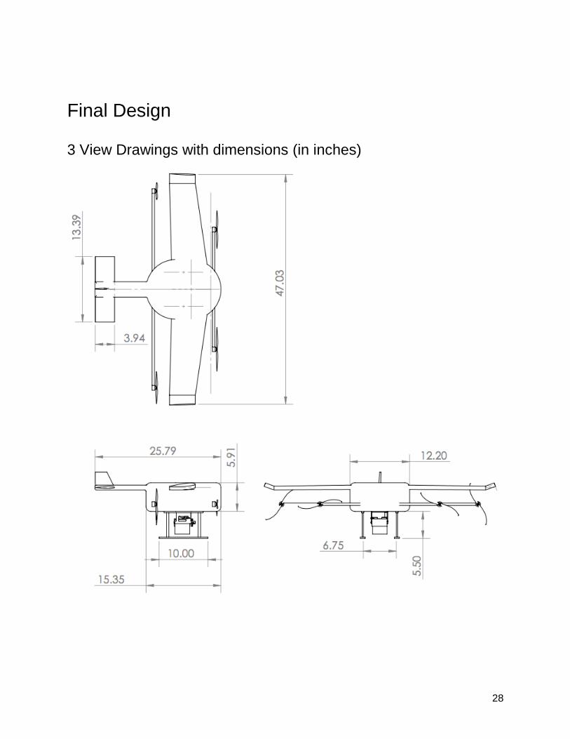
Final Design
3 View Drawings with dimensions (in inches)

29
Renders of hybrid aerial robot in different flight configurations
Cruise Configuration

30
Hover
Configuration
Delivery Mechanism
3D Render

31
Exploded View
3
View Drawings of Delivery Mechanism

32

33
Sized and selected components
Propellers: Our MATLAB optimization yielded .22m as the optimal propeller diameter for our
robot. This is about 8.6 inches, so a good option on sizing would be the Aeronaut Carbon
Electric 8.5 x 7 propellers, which can be found in the UIUC propeller database
ESC’s: Based on our power requirements, at hover we expect each motor to consume around
400W. Calculating our current requirements from a voltage of 14V, we will need ESC’s that can
handle up to around 40 amps. A suitable option is sold by robotshop at the following link.
https://www.robotshop.com/en/t-motor-40a-air-multirotor-esc.html
Motors: Our hover RPM is just under 12,000, so given a typical LiPo battery of 11-14V, that
means we need a motor with a Kv rating of about 1000Kv. A suitable option can be found at the
following link:
https://www.robotshop.com/en/brushless-rotor-motor-1000kv-15a.html
Batteries: We need 496 Watt-hours of battery capacity. Assuming we run all batteries in
parallel, this means we need around 35 amp-hours of capacity (at 14V). The following battery is
1 amp-hour and weighs just under 90 grams. If we use 35 of them, we will come in just under
our allotted battery weight of 3.2 kg, so this seems like a perfect choice to suit our purposes.
https://www.venompower.com/collections/venom-drone-batteries/products/venom-50c-3s-
1000mah-11-1v-fpv-drone-racing-lipo-battery-xt60-ec3-deans-plug

34
Performance Specifications

35

36
Future Directions
We learned many lessons through this aerial robot design project. First, we learned that
delivering a package on time is still an issue with current delivery methods, and drones may be
able to fix this. We learned this in a very ironic fashion: we ordered linear actuators from
Amazon to build our delivery mechanism, and the actuators never arrived due to delays in the
delivery. We also learned the importance of prototyping and iteration. Our first delivery
mechanism prototype was relatively inconsistent and the claw tended to bend when actuated,
rather than move linearly. To combat this, we lasercut the claw again with the inclusion of an
additional pin and slot, to further constrain the motion to the linear direction. This iteration
worked much better and more consistently than did the original version. Further, we also
learned the importance of positioning the battery and delivery mechanism exactly correctly so
that the center of mass would be positioned as expected. There were a few instances during
testing of the drone and delivery mechanism in the d.school in which our pilot attempted to take
off, and the drone’s center of mass was very far towards the back, resulting in the drone
accelerating backwards into a wall. Finally, we learned the importance of making sure to check
a battery’s charge before performing a flight. After two flights during our final waypoints and
delivery checkoff, we decided to fly it a third time without checking the battery’s charge levels.
At the very end of that final flight, the battery ran out of charge and plummeted from the sky and
crashed. If we had checked our battery’s charge before every flight, this would not have
happened.
Using these lessons learned and the process of constructing our drone, we can
extrapolate the mission of delivering a birthday cupcake to many other cases. The main
takeaways from our construction of a robot to delivery a cupcake is that future drone delivery
applications can incorporate the idea that the purpose of drone delivery is not only to deliver the
package and return, but also to provide an experience. Our birthday drone was not only
delivering a cupcake but also adding an element of joy, fun, theatricality, and surprise that
cannot be rivaled by other means of delivery. Additionally, our mission included the concept of
determining in advance what would be the optimal time to takeoff so that the delivery would land
on time. This is an important component that future drone delivery services will need to master.
Further, the importance of being able to deliver to a specific location using a specified path will
be crucial to future drone delivery.
Finally, in order to optimize our aerial robot, there are multiple potential areas for future
development. First, we could actually construct our ideal robot, using the optimized wing and
airfoil design from XFLR5. This would drastically improve the range over our current
quadcopter. Further, we could automate takeoff and landing, so that it does not have to be
manually controlled. Because waypoints and GPS may not be accurate enough to land a drone
on a table, we may need to add some detection systems on the bottom of the drone to be able
to land at a specified target region.
Ultimately, this project allowed us to gain experience in prototyping a working delivery
mechanism to deliver a package to a user. We also were able to optimize the wing and airfoil
design of an ideal robot that would maximize the ability to deliver a cupcake over a large range.