birsinghpur thermal power project … site lies between broad gauge railway line of bilaspur katni...
TRANSCRIPT

SPECIFICATION NO. PE-TS-208-600-C005 VOLUME – IIB SECTION “A”
REV. 00 DATE 22 May, 2004
TITLE: 1X500 MW BIRSINGHPUR TPS
SCOPE OF WORK
SHEET 1 OF 4
C:\Documents and Settings\3060969\My Documents\BIRSINGHPUR\BOP\SECTION A.doc
MADHYA PRADESH STATE ELECTRICITY BOARD
BIRSINGHPUR THERMAL POWER PROJECT 1X500MW
SECTION - A
SCOPE OF WORK
PLANT AUXILLIARY BUILDINGS, NON PLANT BUILDINGS, ROADS, DRAINAGE & ASH SLURRY PIPE
LINE
SPECIFICATION NO. PE-TS-208-600-C005
Bharat Heavy Electricals Limited Project Engineering Management
Power Sector, BHEL House Asian Games Village Complex
Siri Fort, New Delhi-110049

SPECIFICATION NO. PE-TS-208-600-C005 VOLUME – IIB SECTION “A”
REV. 00 DATE 22 May, 2004
TITLE: 1X500 MW BIRSINGHPUR TPS
SCOPE OF WORK
SHEET 2 OF 4
C:\Documents and Settings\3060969\My Documents\BIRSINGHPUR\BOP\SECTION A.doc
1.0 The scope of works covers Civil, Structural and Architectural works for Sanjay Gandhi TPS Unit-5, including supply of all materials, labour, tools and plants. The scope of work is indicative but not limited to the given below.
SCOPE OF WORK
A) CIVIL, STRUCTURAL AND ARCHITECTURAL WORKS FOR ALL
PLANT AUXILLIARY BUILDINGS AND MISC. FOUNDATIONS
Fuel oil pressurizing pump house, switchgear room, tank foundations & dyke paving
Fire water pump house, tank foundations, booster & foam pump house DM water pump house and tank foundation DG building ARCW pump house CPU regeneration building Clarified water pump house and tank foundation Chlorination building CST pump house and tank foundation CW pump house and feed pool Service water tank and pump house
B) CIVIL STRUCTURAL AND ARCHITECTURAL WORKS FOR PLANT FACILITY AND NON PLANT BUILDINGS
All plant roads within plant boundary including road on existing ash
bund along ash slurry pipe line (excluding roads in CHP area from track hopper upto existing boundary wall).
Complete plant drainage system except CHP area. Pipe and cable racks, trenches, road culverts, anchor blocks. Guard pond. CW inlet pipe from pump house to transformer yard including
encasing, road crossings, anchor blocks. CW outlet pipe including encasing from transformer yard to seal pit. Seal pit, debris filter and intake canal from main canal. Septic tanks, soak pits. Canteen building. Technical building. Civil works for electrical earthing system. Ash slurry pipe line support pedestals, culverts, anchor blocks, ash
slurry pipe bridge from existing plant boundary to existing ash bund Mill reject system foundations

SPECIFICATION NO. PE-TS-208-600-C005 VOLUME – IIB SECTION “A”
REV. 00 DATE 22 May, 2004
TITLE: 1X500 MW BIRSINGHPUR TPS
SCOPE OF WORK
SHEET 3 OF 4
C:\Documents and Settings\3060969\My Documents\BIRSINGHPUR\BOP\SECTION A.doc
EXCLUSIONS The following buildings/systems are not covered in the scope of this contract:
Coal Handling Plant Ash Handling Plant within plant battery limit Pre Treatment Plant Effluent Treatment Plant DM Plant within battery limit ESP control building Compressor House Fire protection system (except for buildings/foundations mentioned in
“Scope of work, A”) 2.0 The works to be performed under this contract consist of providing all labour,
supervision, material, scaffolding, construction equipments, tools and plants, temporary works, supplies including POL, transportation and all incidental items not shown or specified but reasonably implied or necessary for the proper completion of work in all respects. Testing of all materials, concrete, earthwork other allied works, preparation of bar bending schedules on the basis of construction drawings, preparation of fabrication drawings etc. are included on the rates of items of work. Works shall only be carried out with approved structural fabrication drawings.
3.0 Supply, Fabrication and erection of structural steel work involving rolled section,
sections fabricated out of plates chequered/ electroforged grating hand rails, primer and final painting for all steel structural works including supply of HSFG Bolts if any, low hydrogen quality electrodes for welding, non destructive testing etc. Complete as per Quality Plan/Customer requirements.
4.0 The area of work shall be cleared of all vegetation, rubbish and other objectionable
matter and materials remove, shall be burnt or otherwise disposed of as directed by the Engineer-in-Charge.
No separate payment for these operations shall be made. The cost of all these operations shall be deemed to have been included in the unit rates rendered for the different items under bill of quantities.
5.0 All the works areas shall be adequately flood lighted to the satisfaction of the
Engineer-in-Charge when the work is in progress during the night shifts. 6.0 The unit rates shall include all material equipment, fixtures, labour construction plant,
temporary works and everything whether of permanent or temporary nature necessary for the completion of job in all respects.

SPECIFICATION NO. PE-TS-208-600-C005 VOLUME – IIB SECTION “A”
REV. 00 DATE 22 May, 2004
TITLE: 1X500 MW BIRSINGHPUR TPS
SCOPE OF WORK
SHEET 4 OF 4
C:\Documents and Settings\3060969\My Documents\BIRSINGHPUR\BOP\SECTION A.doc
7.0 The unit rates quoted for various items of B.O.Q shall include all the stipulations mentioned in Section C and technical specifications under Section D and nothing extra over B.O.Q rates shall be payable.
8.0 Design drawings showing enough details for the construction as per the specification
shall be furnished to the contractor in a phased manner as far as possible. 9.0 The bidder should fully apprise himself of the prevailing conditions at the proposed
site, climatic conditions including monsoon pattern, local conditions, soil strata and site specific parameters and shall include for all such conditions and contingent measures in the bid, including those which may have not been specifically brought out in the specifications.

TITLE: 1X500 MW SANJAY GANDHI TPS, UNIT# 5
PROJECT INFORMATION
SPECIFICATION NO. PE-TS-208-600-C005
VOLUME - II B
SECTION - B
REV.NO. 0 DATE 22 May, 2004
SHEET 1 OF 3
MADHYA PRADESH STATE ELECTRICITY BOARD SANJAY GANDHI THERMAL POWER PROJECT
1X500 MW- UNIT# 5
SECTION - B
PROJECT INFORMATION
PLANT AUXILLIARY BUILDINGS, NON PLANT BUILDINGS, ROADS, DRAINAGE & ASH SLURRY PIPE
LINE
SPECIFICATION NO. PE-TS-208-600-C005
Bharat Heavy Electricals Limited Project Engineering Management
Power Sector, BHEL House Asian Games Village Complex
Siri Fort, New Delhi-110049
C:\Documents and Settings\3060969\My Documents\BIRSINGHPUR\BOP\SECTION B.DOC

TITLE: 1X500 MW SANJAY GANDHI TPS, UNIT# 5
PROJECT INFORMATION
SPECIFICATION NO. PE-TS-208-600-C005
VOLUME - II B
SECTION - B
REV.NO. 0 DATE 22 May, 2004
SHEET 2 OF 3
C:\Documents and Settings\3060969\My Documents\BIRSINGHPUR\BOP\SECTION B.DOC
INTRODUCTION
The Sanjay Gandhi Thermal Power station is being set up at a site about 10 km from Birshingpur Railway Station, District Umaria, Madhya Paradesh. The station shall have an ultimate installed capacity of 4X210MW + 1X500 MW units. Substantial amount of infrastructural and enabling works e.g. land development, boundary wall, construction roads & drainage, construction power and supply arrangements are available. Contractor is advised to visit the site and appraise himself about the conditions of the site and infrastructure available in the area for fulfilling their commitment under the contract.
APPROACH TO SITE
The site lies between broad gauge Railway line of Bilaspur Katni Section of South Eastern Railways and is connected by all weather motorable national and state highways. Nearest railway station is Birshinghpur from where a railway line will branch off to a site for material unloading and coal marshalling. The material consignments shall be as per the restrictions of rail and road transportation prevailing in the country.
TITLE: 1X500 MW SANJAY GANDHI TPS, UNIT# 5
PROJECT INFORMATION
SPECIFICATION NO. PE-TS-208-600-C005
VOLUME - II B
SECTION - B
REV.NO. 0 DATE 22 May, 2004
SHEET 3 OF 3
1. Owner Madhya Pradesh State Electricity Board
2. Owner Consultant Development Consultant Limited,
Park Street,
Kolkata.
3. Project Title Sanjay Gandhi Thermal Power Station
1X500 MW Unit # V
4. Location 10 Km from Birsinghpur Railway Station, District
Umaria, Madhya Pradesh
5. Nearest Railway Stn. Birsinghpur (Madhya Pradesh)
6. Ambient Air Temperature
a. Maximum 48.0 Deg.C
b. Minimum 1.6 Deg.C
7. Relative Humidity
a. Maximum 85%
b. Minimum 19%
8. Rainfall
a. Average annual 1100 mm
9. Wind Data
a. Basic wind speed at 10m height
39 m/sec
b. Wind pressure As per IS: 875 Part III-1984
10. Seismic Zone Zone III as per IS: 1893-2002
C:\Documents and Settings\3060969\My Documents\BIRSINGHPUR\BOP\SECTION B.DOC

SPECIFICATION NO. PE-TS-208-600-C005 VOLUME – IIB SECTION “C”
REV. 00 DATE May/22/04
TITLE: 1X500 MW BIRSINGHPUR TPS SPECIFIC TECHNICAL REQUIREMENT
FOR GENERAL CIVIL WORKS
SHEET 2 OF 19
5/22/2004 SECTION C.doc
MADHYA PRADESH STATE ELECTRICITY BOARD
BIRSINGHPUR THERMAL POWER PROJECT 1X500MW
SECTION - C
SPECIFIC TECHNICAL REQUIREMENTS FOR
GENERAL CIVIL, STRUCTURAL AND ARCHITECHTURAL WORKS
PLANT AUXILLIARY BUILDINGS, NON PLANT
BUILDINGS, ROADS, DRAINAGE & ASH SLURRY PIPE LINE
SPECIFICATION NO. PE-TS-208-600-C005
Bharat Heavy Electricals Limited Project Engineering Management
Power Sector, BHEL House Asian Games Village Complex
Siri Fort, New Delhi-110049

SPECIFICATION NO. PE-TS-208-600-C005 VOLUME – IIB SECTION “C”
REV. 00 DATE May/22/04
TITLE: 1X500 MW BIRSINGHPUR TPS SPECIFIC TECHNICAL REQUIREMENT
FOR GENERAL CIVIL WORKS
SHEET 3 OF 19
5/22/2004 SECTION C.doc
1. GENERAL
Section-C covers specific technical requirements of contract and should be read in conjunction with BOQ, Section-D and other sections of the contract. In case of any conflict between the contents of BOQ and Section-C/Section-D, BOQ will prevail over Section-C/Section-D. In case of any conflict between Section-C and Section-D, Section-C will prevail over Section-D.
2. STEEL STRUCTURAL WORKS
Structural Steel shall conform to IS:2062 Grade – A for rolled steel members or plates up to 20 mm thickness. For plates above 20 mm thickness and welded construction steel conforming to IS:2062 Grade – B (killed and normalized) shall be used except for crane girders where Grade – C (IS:2062) steel shall be used. Steel shall be procured from SAIL or any other approved main producer.
Chequered plate shall conform to IS:3502 (latest) and minimum thickness of chequered plate for floorings, covers etc. shall be 6 mm O/P. All gratings shall be electroforged type. The surface shall be blast cleaned to near white metal surface (SA 2 ½) followed by two coats of redoxide zinc chromate primer and two coats of black color enameled finish paint. Staircase treads shall be provided with anti-skid nosing.
For hand railings GI pipe of medium grade conforming to IS:1239 and galvanizing shall be smooth confirming to IS:2633 shall be used. Hand railing shall be flush welded construction, ground smooth using 32 mm Nominal Bore of 42.2 mm outside diameter pipe, provided with double rail and pipe posts. Top rail shall be provided at 1000 mm above platform or as approved and pipe posts spaced not more than 1500 mm center to center. Hand rails post and rails shall have one coat of red oxide zinc chromate primer. Final painting shall be same as given for painting on structures.
The bidder shall appoint a separate agency, approved by BHEL, for review and
approval of fabrication drawings, in consultation with BHEL, prepared by the bidder.
2.1. CONNECTIONS
Shop connections shall be all welded type and field connections shall generally be bolted type unless specified otherwise. Field bolts, wherever provided, shall be high tensile of 20 mm dia. or of higher diameter and of property class 8.8 (minimum) as per IS:1367 (latest) for all major connections. All bolts, nuts and washers shall be procured from M/S Guest Keen Whalliams (G.K.W) or any other equivalent source approved by BHEL in future. The bolted joints shall be designed for friction type connection and the H.T. bolts shall be tightened to develop the required pre-tension

SPECIFICATION NO. PE-TS-208-600-C005 VOLUME – IIB SECTION “C”
REV. 00 DATE May/22/04
TITLE: 1X500 MW BIRSINGHPUR TPS SPECIFIC TECHNICAL REQUIREMENT
FOR GENERAL CIVIL WORKS
SHEET 4 OF 19
5/22/2004 SECTION C.doc
during their installation. However, the nominal connections in the field like stairs, wall beams shall be done by means of M.S. black bolts, conforming to IS:1363 unless specified otherwise. Welding shall be done in accordance with the recommendation of IS:816 – “Code of Practice for use of metal arc welding for general construction in mild steel” and IS:9595 - “Recommendation for Metal arc welding of Carbon and Carbon Manganese Steels”. Submerged arc welding process shall be used for welding longitudinal fillet welds (connecting flanges with web) and longitudinal/transverse butt joints for fabrication of columns, framing beams, crane girders & and all other built up members unless manual arc welding is specifically required . All electrodes, flux, bare wire etc shall be procured from BHEL approved manufacturers, viz. Advani-Oerlikon, ESAB, D&H or any other equivalent approved source. All butt welds in beams, girders & columns shall be of full penetration. All butt welds shall be radio-graphically or ultrasonically tested as per relevant IS codes and standard practice. The bare wire electrodes for submerged arc welding shall conform to IS:7280. The combination of wire and flux shall satisfy requirement of IS:3613. Flux and wire combination for submerged Arc welding of Structural steel shall be as follows : Filler wire shall be Automelt Gr-C wire of classification AWS-A-5.17-EH14 and flux shall be of agglomerated type (Automelt Gr.-IV) of classification AWS-A-5.17-F7A2EH 14 of Advani-Oerlikon make. Following connections shall be provided during erection : 1. Welded Connections :
i. Connection of ‘Secondary Beam’ to ‘Main Beam’. ii. Connection of ‘Vertical Bracing’ to ‘Column’. iii. Connection of ‘Vertical Bracing’ to ‘Horizontal Bracing’. iv. Connection of ‘Horizontal Bracing’ to ‘Column’. v. Connection of other secondary structures, subject to approval.
2. HSFG connection (Grade 8.8 bolts)
i. Connection of ‘Crane Girder’ to ‘Column’. ii. Splice of ‘Column’ & Splice of ‘Transverse Frame Girders’. iii. Connection between Crane Girders. iv. Connection of members where tension shall be in the fastener.
3. Bearing Type conection (H.T. bolts Grade 8.8)
i. All removable type connections. ii. Connection of ‘Purlins’ to ‘Roof Truss’.

SPECIFICATION NO. PE-TS-208-600-C005 VOLUME – IIB SECTION “C”
REV. 00 DATE May/22/04
TITLE: 1X500 MW BIRSINGHPUR TPS SPECIFIC TECHNICAL REQUIREMENT
FOR GENERAL CIVIL WORKS
SHEET 5 OF 19
5/22/2004 SECTION C.doc
4. M.S Bolts (Gr. 4.6)
i. Stairs, Wall beams. 5. Low Hydrogen Electrodes as approved by the Engineer shall invariably be
used in the following cases : i. For welding of all important joints such as Butt joints in Columns (flange or web), Butt joints in Main frame Beams (Flange or web) etc. ii. For welding steel having thickness more than 20 mm. In case of fillet weld between two components, the thickness of the thicker part shall be considered as the limit for (ii)
Minimum preheat & inter pass temperatures for welding over 40mm to 63 mm (thickness of the thicker part at the point of welding) shall be 66° C and for over 63 mm, it shall be 110° C. However, higher preheat & inter pass temperatures may be required due to joint restraint etc and shall be followed as per approved welding procedure. Shop primer paint shall be two coats of Red Oxide Zinc Chromate Primer and shall conform to IS:2074 in all respects. The surface preparation shall be done in accordance with IS:1477 (Part I & II) – Code of Practice for finishing of Ferrous Metals in Buildings. Stainless steel liner in the coal Bunkers shall be of grade AISI – 304 Finish Grade 2 B (Cold Rolled, Annealed & Pickled and Skin passed) and shall be provided on the inner faces of entire inclined portion of Hoppers and mouth of the Hoppers, without allowing any projections in coal flow path. The electrode classification as per AWS shall be as follows :
i/ For welding of stainless steel to stainless steel : E308D
ii/ For welding of stainless steel to mild steel : E309 Design Of Connections
i/ Fabrication drawings shall be prepared according to the provision of IS:800,
IS:816, IS:9595, IS:1367 and IS:9178. ii/ Connection of vertical bracings with connecting members and diagonals of truss
members shall be designed for full tensile capacity of the bracings. iii/ Size of fillet weld for flange to web connection for built up section shall be as
follows :
a. Full shear capacity or actual shear which ever is more for box section.

SPECIFICATION NO. PE-TS-208-600-C005 VOLUME – IIB SECTION “C”
REV. 00 DATE May/22/04
TITLE: 1X500 MW BIRSINGHPUR TPS SPECIFIC TECHNICAL REQUIREMENT
FOR GENERAL CIVIL WORKS
SHEET 6 OF 19
5/22/2004 SECTION C.doc
b. 80% of full shear capacity or actual shear (if indicated in drawings) or 0.5 times of the web thickness which ever is more. For I section Weld shall be double fillet.
c. All welds shall be continuous. The minimum size of the fillet weld shall be as per relevant IS code .
iv/ Shear connections shall be designed for 75% of section strength for rolled sections
and 80% of section strength for built up section or rolled section with cover plates. Designed shear force shall be more than actual shear.
v/ Moment connections between beam and column shall be designed for 100% of
moment capacity of the beam section. vi/ All butt welds shall be full penetration butt welds. vii/ The connection between top flange & web of crane girder shall be full penetration
butt weld & for bottom flange, connection may be fillet weld. viii/Connection of base plate & gusset members with the columns shall be done
considering that total load gets transferred through weld. ix/ Splicing : All splicing work shall be full strength. Field splicing shall be done
with web /flange cover plates. For, exceptional cases the field splicing shall be designed for 50% of load carried by the cover plates and remaining 50% load through full penetration butt weld. Shop splicing for all sections other than rolled shall be carried out by full penetration butt welds with no cover plates. Splicing for all rolled sections shall be carried out using web and flange cover plate.
2.2.Minimum Tests To Be Carried Out During Fabrication & Erection Of
Structural Steel
1. Steel Ultrasonic test: plates above 25mm thickness shall be subjected to ultrasonic test as per ASTM-A435 or equivalent to check the presence of Lamination. 2. Fillet Weld Dye penetration test : 5% of the total length, Dye penetration shall be carried out to the root run. 3. Butt Weld
Dye penetration test: 10% of the total length, Dye penetration test shall be carried out to the root run after back gouging. Radiography: Generally, splicing shall not be provided in tension flange of Bunker Girders. Spot radiography shall be carried out on 100% joints in Tension zone &10% joints in compression zone. Minimum 300 mm length shall be spot radio-graphed. When radiograph is not possible ultrasonic test shall be carried out after grinding the

SPECIFICATION NO. PE-TS-208-600-C005 VOLUME – IIB SECTION “C”
REV. 00 DATE May/22/04
TITLE: 1X500 MW BIRSINGHPUR TPS SPECIFIC TECHNICAL REQUIREMENT
FOR GENERAL CIVIL WORKS
SHEET 7 OF 19
5/22/2004 SECTION C.doc
surface with prior approval of Engineer. Ultrasonic Test: 10% of all other Butt welds shall be subject to spot radiographic test and the entire balance butt weld for ultrasonic test.
2.3. Painting of Structures
Material Material shall be highest- grade products and shall be delivered to the site in original sealed containers, bearing brand name, manufactures name and colour shade with labels intact and seals unbroken. All materials shall be subject to the inspection, analysis and approved by the Engineer. For satisfactory results, it is desired that primer and finishing paints etc. are to be obtained by the bidder from the same manufacturer. All paints shall be subject to analysis from random sample taken at site from painters bucket, if so desired by the Engineer. Paint shall be stirred frequently to keep the pigment in suspension. Paint shall be ready mixed in original sealed container as packed by the paint manufacturer. Paints purchased for the work shall be brought to site in sealed container and shall be opened in the presence of the Engineer or his authorized representative. Paints, primers etc required under this contract should be procured from approved manufacturers, viz. Berger Paints or any other equivalent sources approved by BHEL. In this regard, BHEL's decision is final and binding to the bidder. Each and every supply of primer, finishing paints, etc. should be accompanied by manufacturer’s test certificates. At the time of procurement, the bidder should furnish all the procurement details to BHEL i.e., the type of material procured (primer, finishing paints etc.), quantity, source of procurement and shall submit all test certificates to BHEL. Bidder shall supply the paints in the exact colour / shade and type of finish of the paint, as per direction of BHEL and no extra payment shall be entertained by BHEL for the above. All colours shall be approved by Engineer and tinting and matching shall be done to the satisfaction of the Engineer. In such case where samples are required they shall be executed in advance with the specified materials for the approval of the Engineer. Primer (Red Oxide Zinc Cromate) The primer shall be Red Oxide Zinc Chromate conforming to the requirements of IS:2074 (Latest) Ready Mixed Paint, Air Drying, Red Oxide Zinc Chromate primer. The primer should conform all the requirements of IS code and any deviation in any respect from IS code shall not be accepted. The paint should be approved by the Engineer. Finishing Coats (Synthetic Enamel Paint) The finishing coats shall be Synthetic Enamel paint conforming to IS:2932 (Latest)- “Enamel Synthetic, Exterior: (A) Undercoating (B) Finishing – Specification”. The

SPECIFICATION NO. PE-TS-208-600-C005 VOLUME – IIB SECTION “C”
REV. 00 DATE May/22/04
TITLE: 1X500 MW BIRSINGHPUR TPS SPECIFIC TECHNICAL REQUIREMENT
FOR GENERAL CIVIL WORKS
SHEET 8 OF 19
5/22/2004 SECTION C.doc
paint shall give a smooth, hard, durable and glossy finish to all surfaces. Bidder shall supply the paints in the exact colour / shade and type of finish of the paint, as per direction of BHEL and no extra payment shall be entertained by BHEL for the above. The paint should conform to all the requirements of IS code and any deviation in any respect from IS code shall not be accepted. The paint should be approved by the Engineer. Surface Preparation And Pre-Treatment (Structure) The surface preparation shall be done in accordance with IS:1477-Part-I (latest)- “Code of Practice for painting of Ferrous Metals in Buildings: Part I (Pre-Treatment)” and as directed by the Engineer. The metal surfaces shall be absolutely clean, dry and free from rust, scales, weld stag, flux deposit, soap films, wax, dirt, oil, grease, foreign matters like cement mortar, etc. and free from existing loose red oxide zinc chromate primer and should be removed by means of wire brushes. Hand-scrappers, sand paper, emery cloth, emery papers, mechanical power tools, etc. or by other effective methods, Such as using solvent cleaning etc. where necessary and as per relevant IS codes and as directed by the Engineer. It should be remembered that perfectly clean surface is of great importance while dealing with die painting of ferrous metal. The surfaces should be carefully inspected and in cases, where the existing red oxide primer is removed while cleaning the surfaces, the damaged portion should be thoroughly degreased by clean solvent swabbing, any corrosion products formed should be thoroughly removed and touched up with a coat of red oxide zinc chromate primer. No extra payment shall be entertained by BHEL for the above. The actual painting work should be commenced only after obtaining clearance from the Engineer or his authorized representative regarding proper cleaning of the surface. Application (Structure)
General The painting work shall be carried out as per the colour scheme of BHEL or as per direction of the Engineer and the Bidder shall procure the paints accordingly. The method of application shall be as recommended by the manufacturer. In case of selection of special shades and colour (not available in standard shades) the Bidder shall mix different shades and prepare test panels of minimum size 1 meter square as per instruction of the Engineer and obtain his approval prior of application of finishing paints. Immediately after the preparation of the surface, and providing the touch of primer in the damaged area, the first coat of primer shall be provided by brush and ensuring a continuous film Without ‘holidays'. After the first coat is hard dry, apply a second coat of primer so that a film perfectly free from 'holidays' is obtained. The second or subsequent finishing coats may be applied after the first finishing coat is hard dry and its gloss is knocked off by scuffing with a very fine cutting device. The surface should be dry, clean, and free from dust and moisture before subsequent coat is

SPECIFICATION NO. PE-TS-208-600-C005 VOLUME – IIB SECTION “C”
REV. 00 DATE May/22/04
TITLE: 1X500 MW BIRSINGHPUR TPS SPECIFIC TECHNICAL REQUIREMENT
FOR GENERAL CIVIL WORKS
SHEET 9 OF 19
5/22/2004 SECTION C.doc
applied. it is essential to avoid corrosion or any other paint defects, which may result due to trapped of foreign materials in the paint film. All painting work shall be done in accordance with relevant I. S codes. Proper tools and implements shall be used. Scaffoldings, if used, shall be independent of the surface to be painted to avoid shade differences of the freshly repaired anchor holes. Painting shall be done by skilled labours in a workman like manner. All materials shall be applied evenly and thoroughly so as to be free of sags, runs, crawls or other defects. All coats shall be of proper consistency. In case of application by brush, no brush marks shall be visible. The brushes shall be clean and in good condition before application of paint. The use, conditioning and maintenance of brushes for painting shall conform to the requirements given in Appendix-A of IS:1477-part-II (latest). No work shall be done under conditions that are unsuitable for production of good results. Application of paint which seals the surface to moisture shall. Only be done after the moisture on and below the surface has dried out. All coats shall be thoroughly dry before succeeding coat is applied. Coats of painting as specified are intended to cover surfaces perfectly. In case the surface is not covered properly by applying specified number of coats, further coats shall be applied by the Bidder to conform the paint as per acceptance criteria of this contract. Approval of the Engineer is to be obtained by the Bidder before application of each coat and no paint shall be applied until the surface for painting has been accepted by the Engineer. The sequence of painting of the structural members shall be as per direction of BHEL and binding to the bidder. Finishing coats shall be of exact colour and shade as per approved samples and all finish shall be uniform in colour and texture. All parts of mouldings and ornaments shall be left clean and true to finish. The surface, which has to be connected using friction type joint, shall not be applied with primer and finish paint before the completion of site connection. Similarly the portion of columns, which shall be encased in concrete, shall not be applied with primer and finish paint and shall be given a coat of neat cement wash. Minimum Total Thickness Of Paint Painting on ferrous metal surface shall be done as per IS:1477(part I &II). The total dry film thickness of the finished paint should not be less than 100 microns, including whatever may available dry film thickness of the existing red oxide zinc chromate primer. The thickness shall be measured by alcometer or any other approved method as directed by the Engineer. Painting in Chemical resistant area
All structures in chemical resistant areas shall be painted with epoxy paint over 2 course of epoxy based zinc phosphate primer. Total DFT shall be minimum 100

SPECIFICATION NO. PE-TS-208-600-C005 VOLUME – IIB SECTION “C”
REV. 00 DATE May/22/04
TITLE: 1X500 MW BIRSINGHPUR TPS SPECIFIC TECHNICAL REQUIREMENT
FOR GENERAL CIVIL WORKS
SHEET 10 OF 19
5/22/2004 SECTION C.doc
microns. Surface preparation shall be done by means of sand/shot blasting, which shall confirm to SA2 ½ swiss standard.
2.4. CONCRETE WORK FOR MACHINE FOUNDATIONS
2.5. General
Concrete work shall be carried out as per IS:456. Mix design concrete shall be used for all areas other than lean concrete work and plain cement concrete where nominal/volume mix can be permitted. Design mix shall be carried out as per IS:10262. Unless specified 20mm and down aggregates shall be used for all structural concrete works. However 40mm and down aggregates may also be used under special conditions for the mass concreting in foundation.
2.6. Special requirements for concreting
Coarse Aggregates Sound and durable crushed stone aggregates shall be used. All aggregates shall be tested for alkali aggregate reaction. Materials which contain high percentage of reactive silica shall not be used. In exceptional cases of high percentage of reactive silica content, aggregate may be allowed where low alkali content cement shall be used. Lime stone aggregate shall not generally be used for foundations which are subjected to high temperature and repeated temperature cycles (like in the case of all machine foundations).However, in case other types of suitable aggregate is not available, the Engineer may allow the use of lime stone aggregate provided the Bidder gets the sample tested from a reputed testing laboratory for satisfactory performance under high temperature and repeated temperature cycle. Unless otherwise specifically approved by the engineer, the tests shall be carried out for a temperature range from 10 0 C to 65 0 C and for 60 (sixty) temperature cycles.
Temperature Control of Concrete The temperature of fresh concrete shall not exceed 230 C when placed. For maintaining the temperature of 230 C in the top decks of machine foundations, crushed ice shall be used in mixing water.
Admixture Plasticizer-cum retarder type admixture shall generally be added to the concrete for promoting workability in addition to retarding setting time, for mass concreting work.
3. MATERIALS
All materials shall be tested quality conforming to latest relevant I.S. Code.
Cement : Fly Ash based Portland Pozzolona cement and Portland cement conforming to IS 12269, IS : 455 shall be procured from ACC, Lafarge, L & T or any other approved main producer.

SPECIFICATION NO. PE-TS-208-600-C005 VOLUME – IIB SECTION “C”
REV. 00 DATE May/22/04
TITLE: 1X500 MW BIRSINGHPUR TPS SPECIFIC TECHNICAL REQUIREMENT
FOR GENERAL CIVIL WORKS
SHEET 11 OF 19
5/22/2004 SECTION C.doc
Fine aggregate (Sand) : shall conform to relevant IS Codes. Fineness modulus shall be from 2.1 to 2.5 for masonry work, from 2.8 to 3.2 for concrete work. Coarse aggregate : shall be of crushed stone and shall conform to IS 383 & IS 2386. Reinforcement bars : shall conform to IS ; 432 and IS 1786. Re-rolled bar shall not be used. Reinforcement shall be procured from `SAIL’, `TATA’, or any other approved main producer. Structural Steel : shall conform to IS 2062. Formwork: All underground structures shall have ordinary face formwork, except for all exposed faces (e.g. inner sides of water tanks, cable trenches etc). All superstructures shall have fairface formwork using plywood, except for all unplastered faces. For all exposed faces in underground structures and unplastered faces in superstructures, all formwork shall be formed using approved quality BWP type, compreg (densified) plywood with suitable overlay (film faced) and conforming to IS:3513 Part-III to produce a perfectly leveled, uniform and smooth surface. Reuse of such forms may be permitted only after inspection and approval by the engineer, for each such reuse. Any damage to film face shall be cause for rejection. The faces of plywood with suitable overlay shall be dense, smooth and without blisters and patch marks. It shall be of uniform color. Film face shall have minimum 250 GSM (grams/sqm) coating. Bricks : shall be of fly ash, produced in a plant installed by the bidder, conforming to relevant IS Codes and class designation 7.5.
Steel doors, windows & ventilators : shall conform to IS : 1038 and IS 1361 with superior quality fittings. Doors shall be fitted with `Godrej’ make mortice lock with handle on both sides and approved door closer of `Yale’ make or equivalent. For A.C. room, rubber padding of best quality shall be fitted to the bottom of door. Rolling Shutters : shall conform to IS 6248. The curtains of rolling shutter shall be of inter locking scrolls made of hot rolled double dipped galvanized steel lath section of 18 SWG tested mild steel strips at 75 mm rolling centers, locked with galvanized malleable iron clips. The bottom lath shall be coupled to a lock plate fabricated from 3 mm thick galvanized steel plate and security riveted with stiffening angles. Aluminium Doors : shall be with anodized extruded sections of `INDAL’ make or equivalent heavy type fitted with superior quality polished glass 6mm thick and with built in door closer. Aluminium Windows : shall be with anodized extruded sections of `INDAL’ make or equivalent heavy type fitted with superior quality polished glass 4mm thick.
SPECIFICATION NO. PE-TS-208-600-C005 VOLUME – IIB SECTION “C”
REV. 00 DATE May/22/04
TITLE: 1X500 MW BIRSINGHPUR TPS SPECIFIC TECHNICAL REQUIREMENT
FOR GENERAL CIVIL WORKS
SHEET 12 OF 19
5/22/2004 SECTION C.doc
Grouting materials : shall be Conbextra GP –2 of `Fosroc’ make or equivalent for Power House & equipment foundations and Conbextra GP – 1 for other foundations. Acid Alkali resistant tiles : shall be of approved thickness and shall conform to IS 4457 & IS : 4832 (Pt-1).
C.G.I. Sheet : thickness of C.G.I sheet shall not be less than 22 g and minimum grade of galvanization shall be 450gms/m2. Glazing : For glazing, Float Glass (Modi Guard or equivalent) shall be used. Admixtures : Plasticizers-cum-retarder type admixture shall generally be added to concrete for promoting workability in addition to retarding setting time for mass concreting work. Concrete: The minimum cement content in concrete shall be as per IS456-2000.
4. STATUTORY REQUIREMENTS
Bidder shall comply with all the applicable statutory rules pertaining to Factories Act. Fire Safety Rules of Tariff Advisory Committee, Water Act for pollution control, Explosives Act, etc. Provisions of safety, health and welfare according to Factories Act shall be complied with. These shall include provision of continuous walkway minimum 500 wide along the crane-girder level on both sides of building, comfortable approach to EOT crane cabin, railing, fire escape, locker room for workmen, pantry, toilets, rest room, etc. Provisions for fire proof doors number of staircases, fire separation wall, lath plastering/encasing the structural members (in the fire prone areas), type of glazing etc. shall be made according to the recommendations of Tariff Advisory Committee. Statutory clearances and norms of State Pollution Control Board shall be followed. Bidder shall obtain approval of Civil/Architectural drawings from concerned authorities before taking up the construction work.
5. LAYOUT
Before starting the work, the Contractor shall carry out the setting out of foundation and structures and provide levels, with reference to general existing grid and bench mark. If the contractor uses the grid, , bench mark and reference pillar made by other Contractors, he shall coordinate with the Contractor and shall satisfy himself of the accuracy of the reference marks. If he is required to set out the foundation afresh, he shall do so independently with reference to the one existing grid and bench mark which has been followed by other agency at the instruction of the Engineer. In case any discrepancy be found. It shall be immediately brought to the

SPECIFICATION NO. PE-TS-208-600-C005 VOLUME – IIB SECTION “C”
REV. 00 DATE May/22/04
TITLE: 1X500 MW BIRSINGHPUR TPS SPECIFIC TECHNICAL REQUIREMENT
FOR GENERAL CIVIL WORKS
SHEET 13 OF 19
5/22/2004 SECTION C.doc
notice of the engineer for any rectification/modification necessary. No complaint shall be entertained at a later stage. The Contractor shall accurately set out the position for holding down bolts and inserts. If required, in the opinion of the Engineer, he shall construct and maintain pillars for Grid, references and bench marks and maintain them till the completion of the construction. He shall also help the Engineer with instruments, materials and labours for checking the detailed lay outs and levels. The Contractor shall be solely responsible for the correctness of the layout and levels, and Engineer’s approval shall not be deemed to imply any warranty in carrying out the work correctly.
5.1. WORKMANSHIP
Workmanship shall be of the best possible quality and all work shall be carried out by skilled workmen except for those which normally requires unskilled persons. Welding shall be done by experienced and certified welders in proper sequence using necessary jigs and fixtures. Fabrications shall be done in shops having proper equipment for accurate edge planning and milling of column shall ends, base late surfaces etc. and shaping and dimensioning of anchor bolt assembly, inserts and other misc. items. In addition to the requirement specified above, if the bye-laws of the local Govt., Municipal or other authorities require the employment of licensed or registered wokmen for various traders, the contactor shall arrange to have the work done by such registered or licensed personnel. In case of manufactured materials, the Contractor shall have, with no additional cost the owner, the services of the supervisors of the manufacturers to achieve that the work is being done according to the manufacturer’s specifications.
6. TEMPORARY WORK
All scaffoldings, staging, temporary bracing and other necessary temporary work required for proper execution of the Contract shall be provided by the Contractor at his own cost and inclusive of all materials, labour, supervision and other facilities.
The layout and details of such Temporary work shall have the prior approval of the Engineer as agreed, but the Contractor shall be responsible for proper strength and safety of the same. All Temporary work shall be so constructed as not to interfere with any permanent work or with the work by other agencies. If it is necessary to remove any of the temporary work at any time to facilitate execution of the work or with the work of other agencies, such removal and re-erection, if required, shall be carried out by the Contactor at the discretion of the Engineer without any delay and any extra cost on this account shall be borne by the Contractor.
7. INTERFACE WITH STRUCTURES UNDER OTHER’S SCOPE

SPECIFICATION NO. PE-TS-208-600-C005 VOLUME – IIB SECTION “C”
REV. 00 DATE May/22/04
TITLE: 1X500 MW BIRSINGHPUR TPS SPECIFIC TECHNICAL REQUIREMENT
FOR GENERAL CIVIL WORKS
SHEET 14 OF 19
5/22/2004 SECTION C.doc
a) In cases of interface e.g. structures under other’s scope of supply being supported on structures under scope of this contractor, the same will be discussed and suitably addressed. b) Modification in layout of foundation/structure during detail engineering stage may be necessary to avoid fouling with those under other’s scope. Necessary changes on this account will be made without any extra cost to Owner. c) Necessary engineering is to be done and provisions are to be kept accordingly by the Contractor to construct foundations/underground structures, etc. without disturbing/endangering the constructions done under the scope of other contracts.
8. INSPECTION, TESTING AND QUALITY CONTROL FOR CIVIL WORKS
Sampling and testing for major items of civil works viz earthwork, concreting, structural steel work (including welding), piling etc. shall be carried out in accordance with the requirements of this specification. Wherever nothing is specified relevant Indian Standards may be used, in absence of Indian Standards, equivalent International standards may be used.
The bidder shall submit for BHEL’s approval a detailed field quality assurance programme for civil works before starting of the construction work. This shall include frequency of sampling and testing nature/type of test, method of test, setting of a testing laboratory, arrangement of testing apparatus/equipment, deployment of qualified/experienced manpower, preparation of format for record, Field Quality Plan, etc. Tests shall be done in the field and/or at a laboratory approved by the Engineer and the Bidder shall submit to the Engineer, the test results in triplicate. In addition, the bidder shall furnish the original test certificate from the manufacturer’s of various materials to be used in the construction.
If any work found to be of inferior quality or sub-standard, the same shall be dismantled and shall be redone as per approved quality or relevant standard. BHEL reserve the rights to reject the work of inferior quality. All expenses on account of dismantling and rework shall be born by contractor.
Workmanship and dimensional tolerances shall be checked as stipulated below.
9. PERMISSIBLE TOLERANCE FOR CIVIL WORKS
Cast-in-situ concrete works The dimensions of concrete as cast when compared with those on the drawings shall be within the tolerances given below:
Description of item Structural element
Permissible Deviation in mm
Faces of concrete in foundations and +25 -10

SPECIFICATION NO. PE-TS-208-600-C005 VOLUME – IIB SECTION “C”
REV. 00 DATE May/22/04
TITLE: 1X500 MW BIRSINGHPUR TPS SPECIFIC TECHNICAL REQUIREMENT
FOR GENERAL CIVIL WORKS
SHEET 15 OF 19
5/22/2004 SECTION C.doc
structural members against which backfill is placed
Location of footing (for RCC framed structures only)
+25 -25
Eccentricity of footing 2% of footing width in direction of misplacement but limiting to 50 mm
Top surfaces of slabs and of concrete to receive base plates to be grouted
+5 -5
Alignment of beams, lintels, columns, walls, slabs and similar structural elements
+5 -5
Cross sectional dimensions of walls, slabs and similar structural elements
+5 -5
Deviation from specified dimensions of cross-section of columns and beams
+12 -6
Alignment of holding down bolts without sleeves
+1.5 -1.5
Alignment of holding down bolts with sleeves
+5 -5
Level of holding down bolt assemblies
+10 -10
Embedded parts (in any direction)
+5 -5
Centers of pockets or holes with greatest lateral dimension not exceeding 150 mm
+10 -10
Variation in steps: Riser +1.5 -1.5 Tread +3.0 -3.0 Plumb 3 mm for every meter
subject to a maximum of 10 mm
Form work Levels and heights ± 6 mm Plumb 3 mm for every meter
subject to a maximum of 10 mm
Unevenness of any surface ± 3 mm Length or breadth ± 12 mm Diagonals ± 15 mm
SPECIFICATION NO. PE-TS-208-600-C005 VOLUME – IIB SECTION “C”
REV. 00 DATE May/22/04
TITLE: 1X500 MW BIRSINGHPUR TPS SPECIFIC TECHNICAL REQUIREMENT
FOR GENERAL CIVIL WORKS
SHEET 16 OF 19
5/22/2004 SECTION C.doc
Masonry All masonry shall be built true and plumb within the tolerances prescribed as below Care shall be taken to keep the perpends properly aligned.
i. Deviation in verticality in total height of any wall of a building more than one storey in height shall not exceed ± 12.5 mm
ii. Deviation from vertical within a storey shall not exceed ± 6 mm for 3 m. height.
iii. Deviation from the position shown on the plan of any brickwork more than one storey in height shall not exceed 12.5 mm.
iv. Relative displacement between load bearing walls in adjacent storeys intended to be in veritical alignment shall not exceed 6 mm.
v. Deviation of bed joint from horizontal in any length upto 12 m shall not exceed 6 mm and in any length over 12 m it shall not exceed 12.5 mm total.
vi. Deviation from the specified thickness of bed-joints or perpends shall not exceed ± 3 mm.
Plastering work The finished plastered surface shall not show any deviation more than 4 mm when checked with a straight edge of 2 meter length placed against the surface.
The thickness of the plaster shall be measured exclusive of the thickness of key i.e. grooves or open joints in brickwork. The average thickness of plaster shall not be less than the specified thickness. The minimum thickness over any portion of the surface shall not be less than the specified thickness by more than 3 mm for plaster thickness above 12 mm and 1 mm for ceiling plaster. Extra thickness required in dubbing behind rounding of the corners at junctions of wall or in plastering of masonry cornices etc. shall be ignored.
Pre-cast concrete work
Length ± 0.1 percent subject to minimum of -5 mm and maximum of +10 mm.
Cross-sectional dimensions ± 3 mm or ±0.1 percent which ever is greater
Straightness of Bow : 1/750 of the length subject to minimum of – 5 mm and maximum of + 10 mm
Squareness : When considering the squareness of the corner, the length of the two adjacent sides being checked shall be taken as the base line. The shorter side shall not vary in length from the perpendicular by more than 5 mm
Flatness : The maximum deviation from a 1.5 m straight edge placed in any position on a nominal plane surface shall not exceed 5 mm.
Reinforcement work
Description of item Structural element Permissible Deviation in mm (Max.)

SPECIFICATION NO. PE-TS-208-600-C005 VOLUME – IIB SECTION “C”
REV. 00 DATE May/22/04
TITLE: 1X500 MW BIRSINGHPUR TPS SPECIFIC TECHNICAL REQUIREMENT
FOR GENERAL CIVIL WORKS
SHEET 17 OF 19
5/22/2004 SECTION C.doc
Placing of reinforcement For effective depth 200 mm or less +10 -5 For effective depth more than 200 mm or +15 -10 Cover to reinforcement - -5 Cutting of reinforcement When minimum length specified +75 - When maximum or minimum length not specified +75 -25
Structural steel work Tolerances on dimensions for fabrication of steel structures shall be according to IS:7215
Tolerances on dimensions for erection of steel structures shall be according to IS:12843
10. WATERPROOFING
All roofs shall be provided with extra heavy duty water proofing treatment comprising of 10 courses, using four layers hessian based bitumen felt, five layers of bitumen paint and finished with 20 mm thick pressed precast concrete tiles on 15 mm thick 1:4 cement sand mortar underbed. Waterproofing treatment should be laid over 75 mm thick foam concrete insulation blocks. The insulation shall be provided with longitudinal and transverse expansion joints. Cement sand plaster shall be laid on the top of foam concrete blocks for providing smooth surface for laying of water proofing treatment.
For underground structures the following treatment shall be given:
1. Chemical injection grouting.
2. Polymer modified cementitious coating on earthside face as per the following:
a. On the outer face of the walls, frames and roof slabs coming in contact with earth, polymer modified cementitious coating in two layers (slurry mix application) as per manufacturers specification shall be provided directly on the concrete surface
b. 50 thk PCC (1:2:4 with 10 nominal size aggregate) shall be provided under the raft i.e. over the lean concrete, followed by polymer modified cementitious coating in two layers (slurry mix application) as per manufacturers specification. 50 thk PCC (1:2:4 with 10 mm nominal size aggregate) shall then be laid over the polymer modified cementitious coating before laying the raft.
SPECIFICATION NO. PE-TS-208-600-C005 VOLUME – IIB SECTION “C”
REV. 00 DATE May/22/04
TITLE: 1X500 MW BIRSINGHPUR TPS SPECIFIC TECHNICAL REQUIREMENT
FOR GENERAL CIVIL WORKS
SHEET 18 OF 19
5/22/2004 SECTION C.doc
The contractor shall give guarantee in writing for all works executed under this specification supplemented by a separate and unilateral guarantee from the specified agency for the waterproofing treatment work. The guarantee shall be for the material and the workmanship for 20 years. The mode of execution of guarantee shall have to be acceptable to BHEL/Customer.
11. CONSTRUCTION / ERECTION METHODOLOGY
11.1. Construction excavation activities shall be fully mechanized from the start of the work.
11.2. All excavation and backfilling work shall be done using excavators, loaders dumpers, dozers, poclains, excavator mounted rock breakers, rollers, sprinklers, water tankers, etc. Manual excavation can be done only on isolated place with specific approval of engineer.
11.3. For controlled rock blasting, specialized agency equipped with sensors to assess the impact of the blast on the adjoining existing structures, shall be employed.
11.4. Dewatering shall be done using the combination of electrical and stand-by diesel pumps to maintain dry working conditions for all activities upto filling/testing, waterproofing, concreting, pitching etc.
11.5. Pile installation equipment suitable for flushing with air lift technique shall be used for construction of bored piles (if required).
11.6. For concreting, weigh batching plants, transit mixers, concrete pumps, hoists, etc. shall be used.
11.7. All fabrication and erection activities of structural steel shall be carried out using automatic submerged arc welding machines, cutting machine, gantry cranes, crawler/tyre mounted heavy cranes and other equipments like heavy plate bending machines, shearing machines, lathe, milling machines etc. Use of derricks shall not be permitted.
11.8. All handling of materials shall be with cranes. Heavy tailors shall be used for transportation.
11.9. Mechanized modular units of scaffolding and shuttering shall be used. 11.10. Grouting shall be carried out using hydraulically controlled grouting
equipment. 11.11. Roadwork shall be done using pavers, rollers and premix plant. 11.12. All finishing items shall be installed using appropriate modern mechanical
tools. Manual punching etc. shall not be permitted. 11.13. Heavy duty hoist for lifting of construction materials shall be deployed.
Compressors for cleaning of foundations and other surfaces shall be used. 11.14. Field laboratory shall be provided with all modern equipment for survey,
testing of soil, aggregates, concrete, welding etc. For testing of steel works, ultra sonic testing machines, radiographic testing machines, dye penetration test equipment, destruction testing equipment, etc shall be deployed.
11.15. All persons working at site shall be provided with necessary safety equipment and all safety aspects shall be duly considered for each construction/erection

SPECIFICATION NO. PE-TS-208-600-C005 VOLUME – IIB SECTION “C”
REV. 00 DATE May/22/04
TITLE: 1X500 MW BIRSINGHPUR TPS SPECIFIC TECHNICAL REQUIREMENT
FOR GENERAL CIVIL WORKS
SHEET 19 OF 19
5/22/2004 SECTION C.doc
activity. Moreover, only the persons who are trained in the respective trade shall be employed for executing that particular work.
11.16. Fabrication and Erection of all site fabricated columns shall be done in single piece unless otherwise provided for in the approved drawings. Main columns of the power house building and bunker building can have maximum of one number of the erection splice. All shop and site splice shall suitably staggered. The erection splice shall be provided with full strength splice cover plate over the butt weld. Conveyor gallery shall be erected as box i.e. all member are welded/bolted prior to erection. Contractor shall submit the erection scheme for the erection of all type of structures and carryout the erection work only after approval of the scheme by the owner.

SPECIFICATION NO. PE-TS-208-600-C005 VOLUME – IIB SECTION “C”
REV. 00 DATE May/22/04
TITLE: 1X500 MW BIRSINGHPUR TPS SPECIFIC TECHNICAL REQUIREMENT
FOR GENERAL CIVIL WORKS
SHEET 20 OF 19
5/22/2004 SECTION C.doc
ANNEXURE - I
BIDDER SHALL PROVIDE MINIMUM FOLLOWING FACILITIES IN THE FIELD LABORATORY FOR MATERIAL TESTING
General Equipment
Sl.No. Description Sl.No. Description 1. Balances 10. Burette stand 2. Drier 11. Pippette 3. Thermometer 12. Wooden mallet 4. Hydrometer 13. Hair brush 5. Hand-scoop 14. Wire Brush 6. Glass beakers 15. Buckets 7. Measuring Cylinder 16. Test Tubes 8. Desiccator 17. Working platforms 9. Burette 18. Alcometer
Soil testing apparatus for conducting the following tests: Particle size analysis and index properties of soil
Moisture-density relations of soil
Specific gravity of soil
Density of soil in place by sand replacement method
Testing Equipment for conducting the following tests on concrete samples: Compressive strength of concrete
Slump of concrete
Specific gravity and absorption and bulking of fine aggregates
Sieve analysis of fine aggregates and coarse aggregates
Tests equipment for conducting the following tests on welds for fabricated structural steel members:
Dye penetration test
Ultrasonic test
TITLE:
TECHNICAL SPECIFICATION FOR GENERAL CIVIL WORK
SPECIFICATION NO. PE-TS-208-600-C005
VOLUME - II B
SECTION - D
REV.NO. 0
SHEET 1 OF 2
VOLUME: II B
SECTION – D
TECHNICAL SPECIFICATIONS FOR
GENERAL CIVIL WORKS
SPECIFICATION NO. PE-TS-208-600-C005
Bharat Heavy Electricals Limited Project Engineering Management
Power Sector, BHEL House Asian Games Village Complex
Siri Fort, New Delhi-110049
C:\Documents and Settings\3060969\My Documents\BIRSINGHPUR\BOP\SectionD(bir)\SECTION-D1.DOC

TITLE:
TECHNICAL SPECIFICATION FOR GENERAL CIVIL WORK
SPECIFICATION NO. PE-TS-208-600-C005
VOLUME - II B
SECTION - D
REV.NO. 0
SHEET 2 OF 2
C O N T E N T S VOLUME II B : TECHNICAL SPECIFICATIONS FOR GENERAL CIVIL WORKS
SUB-SECTION NO. DESCRIPTION PAGES C1 EARTHWORK IN EXCAVATION AND BACKFILLING 20 C2 CEMENT CONCRETE (PLAIN & REINFORCED) 55 C3 CARPENTRY AND JOINERY 6 C4 ROOF AND UNDERGROUND WATERPROOFING, 12 INSULATION AND ALLIED WORKS C5 METAL DOORS, WINDOWS, VENTILATORS, LOVERS ETC. 15 C6 GLASS AND GLAZING 5 C7 ROLLING STEEL SHUTTERS AND GRILLS 5 C8 MISCELLANEOUS METAL 9 C9 MASONRY AND ALLIED WORKS 11 C10 FINISH TO MASONARY AND CONCRETE 9 C11 PAINTING, WHITEWASH & POLISHING ETC. 12 C12 FLOOR FINISH AND ALLIED WORKS 22 C13 SHEET WORK IN ROOF AND SIDING 6 C14 SUSPENDED CEILING 6 C15 WATER SUPPLY, DRAINAGE AND SANITATION 23 C16 ROAD AND DRAIN 36 C17 FABRICATION OF STRUCTURAL STEEL WORK 40 C18 ERECTION OF STRUCTURAL STEEL WORK 17 C19 ROOF DECKING 7 C20 FALSE FLOORING 6
C:\Documents and Settings\3060969\My Documents\BIRSINGHPUR\BOP\SectionD(bir)\SECTION-D1.DOC

TECHNICAL SPECIFICATION FOR EARTHWORK IN EXCAVATION AND BACKFILLING
SPECIFICATION NO. PE-TS-208-600-C005
VOLUME - II B
SECTION - D | SUB-SECTION – C1
REV.NO. 00
SHEET 1 OF 20
VOLUME: II B
SECTION - D
SUB-SECTION – C1
EARTHWORK IN EXCAVATION AND BACKFILLING
SPECIFICATION NO. PE-TS-208-600-C005
Bharat Heavy Electricals Limited Project Engineering Management
Power Sector, BHEL House Asian Games Village Complex
Siri Fort, New Delhi-110049
C:\Documents and Settings\3060969\My Documents\BIRSINGHPUR\BOP\SectionD(bir)\C01-earthwork1.DOC

TECHNICAL SPECIFICATION FOR EARTHWORK IN EXCAVATION AND BACKFILLING
SPECIFICATION NO. PE-TS-208-600-C005
VOLUME - II B
SECTION - D | SUB-SECTION – C1
REV.NO. 00
SHEET 2 OF 20
C 0 N T E N T
CLAUSE NO. DESCRIPTION SHEET NO. 1.00.00 SCOPE 3 2.00.00 CODES AND STANDARDS 3 3.00.00 EXECUTION 6 4.00.00 TESTING AND ACCEPTANCE CRITERIA 18 5.00.00 RATES AND MEASUREMENTS 18 6.00.0 INFORMATION TO BE SUBMITTED BY THE
BIDDER 19
C:\Documents and Settings\3060969\My Documents\BIRSINGHPUR\BOP\SectionD(bir)\C01-earthwork1.DOC

TECHNICAL SPECIFICATION FOR EARTHWORK IN EXCAVATION AND BACKFILLING
SPECIFICATION NO. PE-TS-208-600-C005
VOLUME - II B
SECTION - D | SUB-SECTION – C1
REV.NO. 00
SHEET 3 OF 20
TECHNICAL SPECIFICATION FOR
EARTHWORK IN EXCAVATION AND BACKFILLING 1.00.00 SCOPE
This specification covers earth work excavation in all types of soil, soft rock and hard rock including setting out, clearing and grubbing, shoring, dewatering, back filling around foundations/pipelines to grade, watering, compaction of fills, testing, approaches, disposal of surplus earth, protective fencing, lighting etc relevant to the structures and locations covered under this contract.
1.01.00 Work To Be Provided By The Contractor
The work to be provided for by the contractor unless specified otherwise shall include but not be limited to the following.
a) Supplying and providing all labour, supervision services including as
required under statutory labour regulations, materials, scaffolding, equipments, tools and plants, transportation etc required for the work.
b) Preparation and submission of working drawings showing the approaches,
slopes, berms, shoring, sumps for dewatering including drainage, space for temporary stacking of soils, disposal area, fencing etc and all other details as may be required by the engineer.
c) Carrying out sampling and testing on fill materials/fills to assess the
quality/moisture content/degree of compaction and submission of the test results whenever required by the engineer.
d) Design, construction and maintenance of Magazine of proper capacity for
storage of explosives for blasting work and removal of the same after completion of the work etc.
1.02.00 Work to be provided by others
No work under this specification will be provided by any agency other than the contractor unless specifically mentioned elsewhere in the contract.
2.00.00 Codes and Standards
All work shall be carried out as per this specification and shall conform to the latest revision and/or replacements of the following or any other Indian Standard (IS) Codes unless specified otherwise.
C:\Documents and Settings\3060969\My Documents\BIRSINGHPUR\BOP\SectionD(bir)\C01-earthwork1.DOC

TECHNICAL SPECIFICATION FOR EARTHWORK IN EXCAVATION AND BACKFILLING
SPECIFICATION NO. PE-TS-208-600-C005
VOLUME - II B
SECTION - D | SUB-SECTION – C1
REV.NO. 00
SHEET 4 OF 20
IS: 1200 Method of measurement of building and civil engineering works, Part-I: Earthwork
IS: 2720 Method of test for soils (Relevant parts) IS: 3764 Excavation work - Code of safety IS: 4081 Safety code for blasting and related drilling operations IS: 4701 Indian Standard Code of Practice for earthwork on Canals IS: 6922 Criteria for safety and design of structures subject to
underground blasts In case of conflict between this specification and those (IS Codes) referred to herein, the former shall prevail. In case any particular aspect of work is not covered specifically by this specification/IS Codes, any other standard practice as may be specified by the engineer shall be followed.
2.01.00 Conformity with Designs
The contractor shall carry out the work as per the approved drawings, specification and as directed by the engineer.
2.02.00 Materials 2.02.01 General
All materials required for the work shall be of the best commercial variety and approved by the engineer.
2.02.02 Material for Excavation
For the purpose of identifying the various strata encountered during the course of excavation, the following classifications are to be followed.
a) Soil
It include all type of soil including laterite and moorum etc with/without any percentage of kankars which can be excavated by normal means such as shovel, pick axe, crow bar, spade etc and those which do not fall under clause 2.02.02 (b) and (c) etc.
b) Soft Rock
C:\Documents and Settings\3060969\My Documents\BIRSINGHPUR\BOP\SectionD(bir)\C01-earthwork1.DOC

TECHNICAL SPECIFICATION FOR EARTHWORK IN EXCAVATION AND BACKFILLING
SPECIFICATION NO. PE-TS-208-600-C005
VOLUME - II B
SECTION - D | SUB-SECTION – C1
REV.NO. 00
SHEET 5 OF 20
It include the rocks (including weathered rock) which are removable by splitting with the help of crow bar, pick axe, wedges, pavement breakers, pneumatic/hydraulic equipments, hammers or such implements etc and not requiring blasting (for excavation) in the opinion of the engineer.
c) Hard Rock
It includes the rocks, which require blasting for excavation in the opinion of the engineer. Where blasting is prohibited for any reasons, the excavation shall be carried out by chiselling or any other method as approved by the engineer. The mere fact that the contractor resorts to blasting shall not classify the soft rock under hard rock.
However, the engineer’s decision on the type of strata encountered during excavation shall be the final and binding on the contractor.
2.02.03 Material for Filling
Material to be used for back filling shall be free from vegetations, roots, salts, rubbish, lumps, organic matter and any other harmful chemicals etc and shall be got approved by the engineer. Normally excavated earth shall be used for back filling. In case such earth contains deleterious salts, the same shall not be used. All clods of earth shall be broken or removed. Where the excavated material is mostly rock and if filling with the same is permitted by the engineer in writing, then the filling with rock shall be done in the following manner. The boulders shall be broken into pieces not exceeding 150mm size in any direction and mixed with fine materials consisting of decomposed rock, moorum or any approved earth to fill the voids as for as possible and the mixture shall then be used for filling.
In case the earth required for backfilling is over and above the earth available from the compulsory excavations within the project area, then borrow areas for obtaining suitable fill material shall be arranged by the contractor himself from outside the plant boundary limits and all expenses including royalties, taxes, duties etc shall be borne by him. The selected earth from the borrow areas shall be got approved by the engineer. The borrowed material shall be free from roots, vegetations, decayed organic matter, harmful salts and chemicals, free from lumps and clods etc. The contractor shall obtain and submit necessary clearances/permissions from the concerned authorities for the borrow areas/materials acquired to the engineer. If specified, the back filling shall be done with clean well-graded sand from approved quarries free from harmful and deleterious materials.
2.03.00 Quality Control
C:\Documents and Settings\3060969\My Documents\BIRSINGHPUR\BOP\SectionD(bir)\C01-earthwork1.DOC

TECHNICAL SPECIFICATION FOR EARTHWORK IN EXCAVATION AND BACKFILLING
SPECIFICATION NO. PE-TS-208-600-C005
VOLUME - II B
SECTION - D | SUB-SECTION – C1
REV.NO. 00
SHEET 6 OF 20
All works shall confirm to the lines, levels, grades, cross sections and dimensions shown on the approved drawings and/or as directed by the engineer. The contractor shall establish and maintain quality control for the various aspects of the work, method of construction, materials and equipments used etc. The quality control operation shall include but not be limited to the following.
Sl. No.
Activity Check
1 Lines, levels & grades (a) By periodic surveys (b) By establishing markers, boards etc
2 Back filling (a) On quality of fill material (b) On moisture content of back fill (c) On degree of compaction achieved
3.00.00 EXECUTION
The contractor shall prepare and submit the detailed drawings/schemes for excavation and back filling works as proposed to be executed by him showing the dimensions as per the construction drawings and specification adding his proposal of slopes, shoring, approaches, dewatering, drainage, berms and compaction etc within 15 days of award of the contract to the engineer for approval.
3.01.00 Setting out
On receiving the approval from the engineer with modifications and corrections if any, the contractor shall set out the work from the control points furnished by the engineer and fix permanent points and markers for ease of periodic checking as the work proceeds. These permanent points and markers shall be fixed at the interval as prescribed by the engineer and shall be got checked and certified by the engineer after whom the contractor shall proceed with the work. It should be noted that this checking by the engineer prior to the start of the work will in no way relieve the contractor of his responsibilities of carrying out the work to true lines, levels and grades as per the drawings and specification. If any errors are noticed in the contractor’s work at any stage, the same shall be rectified by the contractor at his own risk and cost.
3.02.00 Clearing and Grubbing etc
The area to be excavated shall be cleared out of fences, trees, logs, stumps, bushes, vegetation, rubbish, slush etc. Trees upto 300mm girth shall be uprooted. Trees above 300mm girth to be cut shall be approved by the engineer and marked. Cutting of trees shall include removing roots as well.
C:\Documents and Settings\3060969\My Documents\BIRSINGHPUR\BOP\SectionD(bir)\C01-earthwork1.DOC

TECHNICAL SPECIFICATION FOR EARTHWORK IN EXCAVATION AND BACKFILLING
SPECIFICATION NO. PE-TS-208-600-C005
VOLUME - II B
SECTION - D | SUB-SECTION – C1
REV.NO. 00
SHEET 7 OF 20
After the tree is cut and roots taken out, the pot holes formed shall be filled with good earth in 250mm layers and compacted unless directed otherwise by the engineer. The trees shall be cut in to suitable pieces as instructed by the engineer. Before earthwork is started, all the spoils, unserviceable materials and rubbish shall be burnt or removed and disposed to the approved disposal area(s) as specified by the engineer. Useful materials, saleable timber, fire woods etc shall be the property of the owner and shall be stacked properly at the worksite in a manner as directed by the engineer.
3.03.00 Excavation for Foundations and Trenches 3.03.01 General
All excavation shall be done to the minimum dimensions as required for the safety and working facility. In each individual case, the contractor shall obtain prior approval of the engineer for the method he proposes to adopt for the excavation including dimensions, side slopes, shoring, dewatering, drainage and disposal etc. This approval however shall not in any way make the engineer responsible for any consequent loss or damage. The excavation must be carried out in the most expeditious and efficient manner. All excavation in open cuts shall be made true to the line, slopes and grades as shown on the drawings or as directed by the engineer. No material shall project within the dimension of minimum excavation lines marked. Boulders (if any) projecting out of the excavated surfaces shall be removed if they are likely to be a hindrance to the work/workers in the opinion of the engineer.
Method of excavation shall in every case be subject to the approval of the engineer. The contractor shall ensure the stability and safety of the excavation, adjacent structures, services and works etc including the safety of the workmen. If any slip occurs, the contractor shall remove all the slipped materials from the excavated pit without any extra cost to the engineer/owner. All loose boulders and semi detached rocks which are not inside but so close to the area to be excavated and may liable to fall or otherwise endanger the workmen, equipment of the work etc during excavation in the opinion of the engineer shall be stripped off and removed away from the area of excavation. The method to be used for removal shall be such that it should not shatter or render unstable or unsafe the portion, which was originally sound and safe. In case any material not required to be removed initially but later to become loose or unstable in the opinion of the engineer shall also be promptly and satisfactorily removed.
The rough excavation may be carried out upto a maximum depth of 150 mm above the final level. The balance shall be excavated with special care. If directed by the engineer, soft and undesirable spots shall be removed even below the final level. The extra excavation shall be filled up as instructed by the engineer. If the excavation (in all types of soil and rock) is done to a depth greater than that shown on the drawing or as directed by the engineer, the
C:\Documents and Settings\3060969\My Documents\BIRSINGHPUR\BOP\SectionD(bir)\C01-earthwork1.DOC

TECHNICAL SPECIFICATION FOR EARTHWORK IN EXCAVATION AND BACKFILLING
SPECIFICATION NO. PE-TS-208-600-C005
VOLUME - II B
SECTION - D | SUB-SECTION – C1
REV.NO. 00
SHEET 8 OF 20
excess depth up to the required level shall be filled with cement concrete not leaner than 1:4:8 or richer as directed by the engineer at the own risk and cost of the contractor. In case where excavation in soil, soft rock (including weathered rock) and hard rock are involved, the excavation in each stratum shall be carried out separately with the approved methodology and as per the instructions of the engineer. All excavated materials such as rock, boulders, bricks, dismantled concrete blocks etc shall be the property of the owner and shall be stacked separately as directed by the engineer. All gold, silver, oil, minerals, archeological and other findings of importance, trees cut or other materials of any description and all precious stones, coins, treasures, relics, antiquities and other similar things which may be found in or upon the site shall be the property of the owner and the contractor shall duly preserve the same to the satisfaction of the engineer/owner. The contractor shall deliver the same to such person or persons as may be authorized or appointed from time to time by the owner to receive the same. Prior to starting the excavation, the ground level at the location shall be checked jointly with the engineer.
3.03.02 Excavation in All Type of Soil and in Soft Rock
The excavation in all type of soil, soft rock including decomposed rock etc shall be carried out as per the approved proposal and as directed by the engineer. The work shall be carried out in a workmanlike manner without endangering the safety of nearby structures/services or works and without causing hindrance to any other activities in the area. Foundation pits shall not be excavated to the full depth unless construction is imminent. The last 150mm depth shall be excavated once concreting work is imminent. At the discretion of the engineer, the full depth may be excavated and the bed be covered with lean concrete as specified after watering and compacting the bed. As the excavation reaches the required dimensions, lines, levels and grades etc, the work shall be got checked and approved by the engineer. In cases where detoriation of the ground, upheaval, slips etc are expected, the engineer may order to suspend the work at any stage and instruct the contractor to carry out the protection works before the excavation will be restarted.
3.03.03 Excavation in Hard Rock
Hard rocks shall normally be excavated by means of blasting. In case where blasting is prohibited for any reasons, the excavation shall be carried out by chiselling or any other approved method as directed by the engineer. Personnel deployed for rock excavation shall be protected from all hazards such as loose rock/boulder rolling down and from general slips of excavated surfaces. Where the excavated surface is not stable against sliding, necessary supports such as props, bracings or bulkheads shall be provided and
C:\Documents and Settings\3060969\My Documents\BIRSINGHPUR\BOP\SectionD(bir)\C01-earthwork1.DOC

TECHNICAL SPECIFICATION FOR EARTHWORK IN EXCAVATION AND BACKFILLING
SPECIFICATION NO. PE-TS-208-600-C005
VOLUME - II B
SECTION - D | SUB-SECTION – C1
REV.NO. 00
SHEET 9 OF 20
maintained during the period of construction. Where the danger of falling loose rock/boulder from the excavated surfaces deeper than 2m exist, steel mesh anchored to the lower edge of the excavation and extending over and above the rock face adequate to retain the dislodged material shall be provided and maintained.
3.03.04 Blasting
a) General
Storage, handing and use of explosives shall be governed by the current explosive rules/regulations laid down by the Central and the State Governments. The contractor shall ensure that these rules/regulations are strictly adhere to. The following instructions are also to be strictly followed and the instructions wherever found in variance with the above said rules/regulations, the former (instructions) shall be superseded with the later (above said rules/regulations). No child under the age of 16 and no person who is in a state of intoxication shall be allowed to enter the premises where explosives are stored nor they shall be allowed to handle the explosives. The contractor shall obtain licence from the District Authorities for undertaking the blasting work as well as for obtaining and storing the explosives as per Explosives Rules, 1940 corrected upto date. The contractor shall purchase the explosives, fuses, detonators etc only from a licensed dealer and shall be responsible for the safe custody and proper accounting of the explosive materials. The engineer or his authorized representative shall have the access to check the contractor's store of explosives and his accounts at any time. It is the full responsibility of the contractor to transport the explosives as and when required for the work in a safe manner to the work spot. Further, the engineer may issue modifications, alterations and new instructions from time to time. The contractor shall comply with the same without these being made a cause for any extra claim.
b) Materials
All materials such as explosives, detonators, fuses, tamping materials etc proposed to be used in the blasting operation shall have the prior approval of the engineer. Only explosives of approved make and strength are to be used. The fuses known as instantaneous fuse must not be used. The issue of fuse with only one protective coat is prohibited. The fuse shall be sufficiently water resistant as to be unaffected when immersed in water for 30 minutes. The rate of burning of the fuse shall be uniform and shall be not less than 4 seconds per inch of length with 10% tolerance on either side. Before use, the fuse shall be inspected. Moist, damaged or broken
C:\Documents and Settings\3060969\My Documents\BIRSINGHPUR\BOP\SectionD(bir)\C01-earthwork1.DOC

TECHNICAL SPECIFICATION FOR EARTHWORK IN EXCAVATION AND BACKFILLING
SPECIFICATION NO. PE-TS-208-600-C005
VOLUME - II B
SECTION - D | SUB-SECTION – C1
REV.NO. 00
SHEET 10 OF 20
ones shall be discarded. When the fuses are in stock for long, the rate of burning of fuses shall be tested before use. The detonators shall be capable of giving an effective blasting of the explosives. Moist and damaged detonators shall be discarded.
c) Storage of Explosives
The current Explosive Rules shall govern the storage of explosives. Explosives shall be stored in a clean, dry and well-ventilated magazine to be specially built for the purpose. Under no circumstances should a magazine be erected within 400m of the actual work site or any source of fire. The space surrounding the magazine shall be fenced and the ground inside shall be kept clear and free from trees, bushes etc. The admission to this fenced space shall be through a single gate only and no person shall be allowed without the permission of the officer-in-charge. The clear space between the fence and the magazine shall not be less than 90m. The magazine shall be well drained. Two lightning conductors, one at each end shall be provided to the magazine. The lightning conductors shall be tested once in every year. Explosives, fuses and detonators shall each be separately stored. Cases of explosives must be kept clear of the walls and floors for free circulation of air on all sides. Special care shall be taken to keep the floor free from any grains of explosives. Cases containing explosives shall not be opened inside the magazine and the explosives in open cases shall not be received into a magazine. Explosives which appear to be in a damaged or dangerous condition are not to be kept in any magazine but must be removed without delay to a safe distance and be destroyed. Artificial light, matches, inflammable materials, oily cotton, rag waste and articles liable to spontaneous ignition shall not be allowed inside the magazine. Illumination shall be obtained from an electric storage battery lantern. No smoking shall be allowed within 100m distance from any magazine. Magazine shoes without nails shall be used while entering the magazine. The persons entering the magazine must put on the magazine shoes, which shall be provided at the magazine for this purpose and should be careful
* not to put their feet on the clean floor unless the magazine shoes on. * not to touch the magazine shoes on ground outside the clean floor. * not to allow any dirt or grit to fall on the clean floor.
Persons with bare feet shall dip their feet in water before entering the magazine and then step directly from the tub to the clean floor. No person
C:\Documents and Settings\3060969\My Documents\BIRSINGHPUR\BOP\SectionD(bir)\C01-earthwork1.DOC

TECHNICAL SPECIFICATION FOR EARTHWORK IN EXCAVATION AND BACKFILLING
SPECIFICATION NO. PE-TS-208-600-C005
VOLUME - II B
SECTION - D | SUB-SECTION – C1
REV.NO. 00
SHEET 11 OF 20
having article of steel or iron with/on him shall be allowed to enter the magazine. Workmen shall be examined before entering the magazine to check none of the prohibited articles are with them. A brush broom shall be kept in the lobby of the magazine for cleaning the magazine. Cleaning shall be done immediately after each occasion whenever the magazine is opened for receipt, delivery or inspection of the explosives. The mallets, levers, wedges etc for opening the barrels or cases shall be of wood. The cases of explosives are to be carried by hand and shall not be rolled or dragged inside the magazine. Explosives which have been issued and returned to the magazine are to be issued first; otherwise those which have been stored long in the store are to be issued first. Neither the magazine shall be opened nor any person shall be allowed in the vicinity of the magazine during any dust storm or thunderstorm. All magazines shall be officially inspected at definite intervals and a record of such inspections shall be kept.
d) Carriage of Explosives
Detonators and explosives shall be transported separately to the blast site. Explosives shall be kept dry and away from the direct rays of the sun, artificial lights, steam pipes or heated metal and other sources of heat. Before explosives are removed, each case or package shall be carefully examined to ascertain that it is properly closed and shows no sign of leakage.
No person except the driver shall be allowed to travel on the vehicle conveying explosives. No explosive shall be transported in a carriage or vessel unless all iron or steel therein the carriage or vessel which are likely to contact the package containing explosives are effectually covered with lead, leather, wood, cloth or any other suitable material. No light shall be carried on the vehicle carrying explosives and no operation connected with the loading, unloading and handling of explosives shall be conducted after sunset.
e) Use of Explosives
The contractor shall appoint an agent who shall personally superintend the firing and all operations connected therewith. The contractor shall satisfy himself that the person so appointed is fully acquainted with his responsibilities. Holes for charging the explosives shall be drilled with pneumatic drills and the drilling pattern shall be so planned that the rock pieces after blasting will be suitable for handling. The hole diameter shall be of such a size that the cartridges can easily pass down through them and any undue force is not required during charging. Charging operation shall be carried
C:\Documents and Settings\3060969\My Documents\BIRSINGHPUR\BOP\SectionD(bir)\C01-earthwork1.DOC
TECHNICAL SPECIFICATION FOR EARTHWORK IN EXCAVATION AND BACKFILLING
SPECIFICATION NO. PE-TS-208-600-C005
VOLUME - II B
SECTION - D | SUB-SECTION – C1
REV.NO. 00
SHEET 12 OF 20
out by or under the personal supervision of the shot firer. Wrappings shall never be removed from the explosive cartridges. Only one cartridge at a time shall be inserted in a hole and wooden rods shall only be used for loading and stemming the shot holes. Only such quantities of explosives as are required for a particular work shall be brought to the work site. Should any surplus remain when all the holes have been charged shall be carefully removed to a point at least 300m away from the firing point. The authorized shot firer himself shall make all the connections. The shot firing cable shall not be dragged along the ground to avoid any damage to the insulation. The shot firing cable shall be tested each time for its continuity and possible short-circuiting. The shot firer shall always carry the exploder handle with him until he is ready to fire shots. The number of shots fired at a time shall not exceed the permissible limits. Before any blasting is carried out it shall be ensured that all workmen, vehicles and equipment on the site are cleared from an area of minimum 300m radius from the firing point or as required by the statutory regulations at least 10 minutes before the time of firing by sounding a warning siren and the area shall be encircled by red flags. The explosives shall be fired by means of an electric detonator placed inside the cartridge. For simultaneous firing of a number of charges, the electric detonators shall be connected with the exploder through the shot firing cable in a simple series circuit. Due precautions shall be taken to keep the firing circuit insulated from the ground, bare wires, rails, pipes or any other path of stray current etc and keep the lead wires short circuited until it is ready to fire. Any kink in the detonator leading wire shall be avoided. For simultaneous firing of a large number of shot holes, use of cordtex may be done. An electric detonator attached to its side with adhesive tape shall initiate cordtex connecting wire or string. Blasting shall only be carried out at certain specified times to be agreed jointly by the contractor and the engineer. At least five minutes after the blast has been fired in case of electric firing or as stipulated in the regulations, the authorized shot firer shall return to the blast area and inspect carefully the work and satisfy himself that all the charged holes have exploded. Cases of misfired unexploded charges shall be exploded by drilling a parallel fresh hole at a distance of not less than 600mm from the misfired hole and by exploding a new charge. The authorized shot firer shall be present during the removal of debris as it may contain unexploded explosives near the misfired hole. The workmen shall not return to the site of firing until at least half an hour after firing. Where blasting is to be carried out in proximity of other structures, controlled blasting by drilling shallow shot holes and proper muffling arrangements with steel plates loaded with sand bags etc shall be used on top of the blast holes to prevent the rock fragments from causing any
C:\Documents and Settings\3060969\My Documents\BIRSINGHPUR\BOP\SectionD(bir)\C01-earthwork1.DOC

TECHNICAL SPECIFICATION FOR EARTHWORK IN EXCAVATION AND BACKFILLING
SPECIFICATION NO. PE-TS-208-600-C005
VOLUME - II B
SECTION - D | SUB-SECTION – C1
REV.NO. 00
SHEET 13 OF 20
damage to the adjacent structures and other properties. Adequate safety precautions as per building byelaws, safety codes, statutory regulations etc shall be taken during blasting operations.
f) Restrictions in Blasting
a) Blasting which may disturb or endanger the stability, safety or quality
of the adjacent structures/foundations shall not be permitted. b) Blasting within 200m of a permanent structure or construction work in
progress shall not be permitted. c) Progressive blasting shall be limited to two third of the total remaining
depth of excavation. d) No large scale blasting operations will be resorted to when the
excavation reaches the last one metre and only small charge preferably black powder may be allowed so as not to shatter the parent rock
e) The last blast shall not be more than 0.50 m in depth. f) In rocky formations, at locations where specifically indicated or
ordered in writing by the engineer, the use of explosives shall be discontinued and chiselling shall complete excavation or any other suitable method as approved by the engineer.
3.03.05 Disposal
The excavated spoils shall be disposed of in any (or all) of the following manner as directed by the engineer.
a) By using it straightway for backfilling.
b) By stacking it temporarily to use for backfilling at a later date during
execution of the contract. c) i) By either spreading or ii) By spreading and compacting at designated disposal areas. d) By selecting the useful material and stacking it neatly in designated areas
as indicated by the engineer for use in backfilling by some other agency.
3.03.06 Disposal of Surplus Materials
All surplus material from excavation shall be removed and disposed of from the excavation site to the designated disposal area indicated by the engineer.
C:\Documents and Settings\3060969\My Documents\BIRSINGHPUR\BOP\SectionD(bir)\C01-earthwork1.DOC
TECHNICAL SPECIFICATION FOR EARTHWORK IN EXCAVATION AND BACKFILLING
SPECIFICATION NO. PE-TS-208-600-C005
VOLUME - II B
SECTION - D | SUB-SECTION – C1
REV.NO. 00
SHEET 14 OF 20
All good and sound rocks obtained from excavations and all assorted materials of dismantled structures are the property of the owner and if the contractor wants to use it, he shall have to obtain it from the engineer at a mutually agreed rate. All sound rocks and other assorted materials like excavated bricks etc shall be stacked separately.
3.03.07 Protection
The contractor shall notify the engineer as soon as the excavation is expected to be completed within a day so that he shall inspect it at the earliest. Immediately after approval of the engineer, the excavation must be covered up in a shortest possible time. But in no case the excavation shall be covered up or worked on before approval by the engineer. Excavated material shall be placed 1.5m or half the depth (of excavation) whichever is more from the edge of the excavation or further away if directed by the engineer. Excavation shall not be carried out below the foundation level of the structure close by until the required precautions are taken. Adequate fencing is to be made enclosing the excavation. The contractor shall protect all the underground services exposed during excavation. All existing surface drains in the work area shall be suitably diverted by the contractor before taking up excavation to maintain the working area neat and clean.
3.03.08 Dewatering
All excavation shall be kept free of water and slush. Grading in the vicinity shall be controlled to prevent the surface water running into the excavations. The contractor shall remove any water inclusive of rain water and subsoil water etc accumulated in the excavation by pumping or other means as approved by the engineer and keep the excavations dewatered and/or lower the subsoil water level to 300mm below the founding level until the construction of foundation and backfilling are completed in all respects. Sumps made for dewatering must be kept clear of the foundations. The engineer’s prior approval on the method of pumping to be adopted shall be taken; but in any case, the pumping arrangement shall be such that there shall be no movement or blowing in of subsoil due to the differential head of water during pumping.
C:\Documents and Settings\3060969\My Documents\BIRSINGHPUR\BOP\SectionD(bir)\C01-earthwork1.DOC

TECHNICAL SPECIFICATION FOR EARTHWORK IN EXCAVATION AND BACKFILLING
SPECIFICATION NO. PE-TS-208-600-C005
VOLUME - II B
SECTION - D | SUB-SECTION – C1
REV.NO. 00
SHEET 15 OF 20
3.03.09 Timber Shoring
Close or open type timber shoring as approved by the engineer depending on the nature of sub-soil, depth of pit or trench and the type of timbering shall be adopted. Timbers made out of approved quality shall only be used. It shall be the responsibility of the contractor to take all necessary steps to prevent the sides of trenches and pits from collapsing. a) Close Timbering
Close timbering shall be done by completely covering the sides of the trenches and pits generally with short, upright members called "polling boards". These shall be of 250mm wide (min.) and 40mm thick (min.) sections as directed by the engineer. The boards shall generally be placed vertically in pairs, one on each side of the cut and shall be kept apart (maximum spacing is limited to 1.20m) by horizontal walers of strong wood cross strutted with wooden struts or as directed by the engineer. The length of wooden struts shall depend on the width of the trench or pit. In case where the soil is very soft and loose, the boards shall be placed horizontally against the sides of excavation and supported by vertical walers, which shall be strutted to similar timber pieces on the opposite face of the trench or pit. The lowest board supporting the sides shall be taken into the ground. No portion of the vertical side of the trench or pit shall remain exposed to avoid any slipping out of earth. The withdrawal of the timber shall be done very carefully to prevent the collapse of the pit or trench. It shall be started from one end and preceded systematically to the other end. Concrete or masonry shall not be damaged during the removal of the timber. No claim shall be entertained for any timber, which cannot be withdrawn and is lost or buried.
b) Open Timbering
In case of open timbering, vertical board of 250mm wide (min.) and 40mm thick (min.) shall be spaced sufficiently apart to leave unsupported strips of maximum 500mm average width. The detailed arrangement, size of timber and the spacing etc shall be subjected to the approval of the engineer. In all other respects, the specification for close timbering shall apply to open timbering as well.
3.03.10 Treatment of Slips
The contractor shall take all precautions to avoid high surcharges and provide proper surface drainage to prevent flow of water over the sides of the excavations. These precautions along with proper slopes, berms, shoring and control of ground water should cause no slips to occur. If however slips still
C:\Documents and Settings\3060969\My Documents\BIRSINGHPUR\BOP\SectionD(bir)\C01-earthwork1.DOC

TECHNICAL SPECIFICATION FOR EARTHWORK IN EXCAVATION AND BACKFILLING
SPECIFICATION NO. PE-TS-208-600-C005
VOLUME - II B
SECTION - D | SUB-SECTION – C1
REV.NO. 00
SHEET 16 OF 20
occur, the contractor with his own risk and cost shall remove the same. 3.04.00 Backfilling 3.04.01 General
The material to be used for backfilling shall be approved by the engineer which shall be obtained directly from the excavation, from the nearby areas where excavation work by the same agency is in progress, from the temporary stacks of excavated spoils or from the borrow pits as directed by the engineer. The material shall be free from lumps and clods, roots and vegetations, harmful salts and chemicals, organic materials etc. In locations where sand filling is required, the sand used should be clean, well graded and be of the quality normally acceptable for use in concrete.
3.04.02 Filling and Compaction in Pits and Trenches all Around the Structures
As soon as the work in foundation has been accepted, the spaces around the foundation in pits and trenches shall be cleared of all debris, brick bats, mortar droppings etc and filled with approved earth in layers not exceeding 250mm (in loose thickness). Each layer (loose) shall be watered, rammed and properly compacted to the required degree to the satisfaction of the engineer. Earth shall be compacted with approved mechanized compaction machine. Usually, no manual compaction shall be allowed unless specifically permitted by the engineer. The moisture content of the fill material during compaction shall be controlled near to its optimum moisture content so as to obtain the required degree of compaction. The final surface shall be trimmed and levelled to proper profile as desired by the engineer.
3.04.03 Plinth Filling
The plinth shall be filled with earth in layers not exceeding 250mm (in loose thickness) and each layer shall be watered and compacted to the required degree with approved compaction machine or manually if specifically permitted by the engineer. When the filling reaches the finished level, the surface shall be flooded with water for at least 24 hours, allowed to dry and then rammed and compacted in order to avoid any settlement at a later stage. The finished surface of fill shall be trimmed to the slope intended to be provided for the floor.
3.04.04 Filling in Trenches for Water Pipes and Drains
Filling in trenches for pipes and drains shall be commenced as soon as the joints of pipes and drains have been tested and passed. Where the trenches are excavated in soil, the filling shall be done with earth on the sides and top of pipes in layers not exceeding 150mm, watered, rammed and compacted taking
C:\Documents and Settings\3060969\My Documents\BIRSINGHPUR\BOP\SectionD(bir)\C01-earthwork1.DOC
TECHNICAL SPECIFICATION FOR EARTHWORK IN EXCAVATION AND BACKFILLING
SPECIFICATION NO. PE-TS-208-600-C005
VOLUME - II B
SECTION - D | SUB-SECTION – C1
REV.NO. 00
SHEET 17 OF 20
care that no damage is caused to the pipe below. In case of trenches excavated in rock, the filling upto a height of 300mm or the diameter of the pipe whichever is more above the crown of the pipe or barrel shall be done with fine material such as earth, moorum, disintegrated rock or ash as per the availability at site and shall be filled in compacted layers not exceeding 150mm. The remaining filling shall be done in layers with the mixture of boulders (of size not exceeding 150mm) and fine material as specified elsewhere in the specification. Each layer shall be watered, rammed and compacted to the required degree and to the satisfaction of the engineer.
3.04.05 Filling in Disposal Area
Surplus materials from excavation which are not required for backfilling shall be disposed of in the designated disposal areas. The spoils shall not be dumped haphazardly but should be spread in layers approximately 250mm thick when loose, watered and compacted with the help of compacting equipment as per the directions of the engineer. In wide areas, rollers shall be employed and compaction shall be done to the satisfaction of the engineer at the optimum moisture content, which shall be checked and controlled by the contractor. In certain cases the engineer may direct the contractor to dispose the surplus materials without compaction, which can be done by tipping the spoils from a high bench neatly maintaining a proper level and grade of the bench.
3.05.00 Approaches and Fencing
The contractor should provide and maintain proper approaches for the workmen and inspection. The roads and approaches around the excavation should be kept clear at all times so that there is no hindrance to the movement of men, material and equipment of various agencies connected with the project. Sturdy and elegant fencing is to be provided around the top edge of the excavation as well as around the bottom of the fill at the surplus disposal area where dumping from a high bench is in progress.
3.06.00 Lighting
Full-scale area lighting is to be provided if night work is permitted or directed by the engineer. If no night work is in progress, red warning lights should be provided at the corners of the excavated pit and the edges of the fill.
C:\Documents and Settings\3060969\My Documents\BIRSINGHPUR\BOP\SectionD(bir)\C01-earthwork1.DOC

TECHNICAL SPECIFICATION FOR EARTHWORK IN EXCAVATION AND BACKFILLING
SPECIFICATION NO. PE-TS-208-600-C005
VOLUME - II B
SECTION - D | SUB-SECTION – C1
REV.NO. 00
SHEET 18 OF 20
4.00.00 TESTING AND ACCEPTANCE CRITERIA 4.01.00 Excavation
On completion of excavation, the dimension of the pits will be checked as per the drawings after the pits are completely dewatered. The work will be accepted after all undercuts have been set right and all over excavations are filled back to the required lines, levels and grades by placing ordinary cement concrete of 1:4:8 proportion and/or richer and/or by compacted earth as directed by the engineer. The choice of the grade of concrete will be a matter of unfettered discretion of the engineer. Over excavation of the sides shall be made good by the contractor while carrying out the backfilling. The excavation work will be accepted after the above requirements are fulfilled and all the temporary approaches encroaching inside the excavation have been removed.
4.02.00 Backfilling
The degree of compaction required will be as per the stipulation laid down in IS: 4701 and the actual method of measuring the degree of compaction will be as decided by the engineer. The work of back filling will be accepted after the engineer is satisfied with the degree of compaction achieved.
5.00.00 RATES AND MEASUREMENTS 5.01.00 Rates
a) The item of work in the schedule of quantities describes the work very briefly. The various items of the schedule of quantities shall be read in conjunction with the corresponding section in the technical specification including amendments and additions if any. For each item in the schedule of quantities, the bidder’s rate shall include all the activities covered in the description of the items as well as for all necessary operations in detail as described in the technical specification.
b) No claims shall be entertained if the details shown on the released for
construction drawings differ in any way from those shown on the tender drawings.
c) The unit rate quoted shall include minor details which are obviously and
fairly intended and which may not have been included in these documents but are essential for the satisfactory completion of the work.
d) The bidder’s quoted rate shall be inclusive of supplying and providing all
labour, men, materials, equipments, tools and plants, supervision, services, approaches, schemes etc.
C:\Documents and Settings\3060969\My Documents\BIRSINGHPUR\BOP\SectionD(bir)\C01-earthwork1.DOC

TECHNICAL SPECIFICATION FOR EARTHWORK IN EXCAVATION AND BACKFILLING
SPECIFICATION NO. PE-TS-208-600-C005
VOLUME - II B
SECTION - D | SUB-SECTION – C1
REV.NO. 00
SHEET 19 OF 20
C:\Documents and Settings\3060969\My Documents\BIRSINGHPUR\BOP\SectionD(bir)\C01-earthwork1.DOC
e) In case blasting in hard rock is envisaged, the unit rate quoted for earthwork shall include the cost of storage and safety arrangements for the materials required for blasting. No separate payment will be made on this account.
5.02.00 Measurements
Method of measurements are specified in the proceeding sections. Where not so specified, the latest version of IS: 1200, Part-1 shall be applicable. a) The length, breadth and depth shall be measured correct to the nearest
centimetre if measurements are taken by tape. Rounding of numerical shall be as per relevant IS Codes. If the measurements are taken with staff and level, the levels shall be recorded correct to 5mm. The area and volume shall be worked out in square meter and cubic meter respectively correct to the nearest of two decimal places.
b) For earthwork in excavation, the ground levels shall be taken before and
after completion of the work in the actually excavated area. The quantity of earthwork in excavation shall be computed from these levels in cubic meter.
c) Where soft rock and hard rock are mixed, the measurement shall be done
as follows. The two types of rock shall be stacked separately and measured in stacks. The net quantity of each type of rock shall be so arrived by applying a deduction of 50% for looseness/voids in the stacks. If the sum of net quantity of the two types of rock so arrived exceeds the total quantity of the excavation, then the quantity of each type of rock shall be worked out from the total quantity (from excavation) in the ratio of net quantities in stack measurements of the two types of rock. If stacking is not feasible, the method as suggested by the engineer shall be followed.
d) Where soil, soft rock and hard rock are mixed, the measurement shall be
done as follows. The soft and hard rock shall be removed from the excavated material and stacked separately and measured in stacks. The net quantity of each type of rock shall be so arrived by applying a deduction of 50% for looseness/voids in stacks. The difference between the entire excavation and the sum of the quantities of soft and hard rock so arrived shall be taken as soil.
6.00.00 INFORMATION TO BE SUBMITTED BY THE BIDDER 6.01.00 With Tender
Detail of equipments and machineries proposed to be used for excavation, backfilling and compaction shall be submitted along with the tender.
TECHNICAL SPECIFICATION FOR EARTHWORK IN EXCAVATION AND BACKFILLING
SPECIFICATION NO. PE-TS-208-600-C005
VOLUME - II B
SECTION - D | SUB-SECTION – C1
REV.NO. 00
SHEET 20 OF 20
6.02.00 After Award
After award of the contract the successful bidder shall submit the following for approval.
a) Within 30 days of the award of contract, the contractor shall submit a
detailed programme of the work as proposed to be executed giving completion dates of excavation for the various foundations and the time required for backfilling and compaction after completion of foundation for the structures. The earthwork programme shall be planned in accordance with the foundation programme. The programme should also show how the excavation and backfilling quantities will be balanced minimizing the temporary stacking of spoils. It is to be noted that the engineer even after initial approval of the programme may instruct the contractor to enhance or to retard the progress of work during the actual execution in order to match with the progress of foundations. The initial programme being submitted by the contractor should have sufficient flexibility to take care of such reasonable variations.
b) Within 15 days of the award of contract, the contractor shall submit the
drawings for earth work in excavation and backfilling showing detail of slopes, shoring, approaches, sump pits, dewatering lines, fencing etc for the approval of the engineer.
C:\Documents and Settings\3060969\My Documents\BIRSINGHPUR\BOP\SectionD(bir)\C01-earthwork1.DOC

TITLE:
TECHNICAL SPECIFICATION FOR CEMENT CONCRETE (PLAIN & REINFORCED
SPECIFICATION NO. PE-TS-208-600-C005
VOLUME - II B
SECTION - D | SUB-SECTION – C2
REV.NO. 0
SHEET 1 OF 55
VOLUME: II B
SECTION - D
SUB-SECTION – C 2
CEMENT CONCRETE (PLAIN & REINFORCED)
SPECIFICATION NO. PE-TS-208-600-C005
Bharat Heavy Electricals Limited Project Engineering Management
Power Sector, BHEL House Asian Games Village Complex
Siri Fort, New Delhi-110049
C:\Documents and Settings\3060969\My Documents\BIRSINGHPUR\BOP\SectionD(bir)\C02-pcc_rcc1.DOC

TITLE:
TECHNICAL SPECIFICATION FOR CEMENT CONCRETE (PLAIN & REINFORCED
SPECIFICATION NO. PE-TS-208-600-C005
VOLUME - II B
SECTION - D | SUB-SECTION – C2
REV.NO. 0
SHEET 2 OF 55
C 0 N T E N T
CLAUSE NO. DESCRIPTION SHEET NO.
1.00.00 SCOPE 3 2.00.00 GENERAL 3 3.00.00 INSTALLATION 11 4.00.00 SAMPLING AND TESTING 41 5.00.00 ACCEPTANCE CRITERIA 43 6.00.00 RATES AND MEASUREMENTS 44 7.00.00 LIST OF I.S.: CODES AND STANDARDS
FOR REFERENCE 50
C:\Documents and Settings\3060969\My Documents\BIRSINGHPUR\BOP\SectionD(bir)\C02-pcc_rcc1.DOC

TITLE:
TECHNICAL SPECIFICATION FOR CEMENT CONCRETE (PLAIN & REINFORCED
SPECIFICATION NO. PE-TS-208-600-C005
VOLUME - II B
SECTION - D | SUB-SECTION – C2
REV.NO. 0
SHEET 3 OF 55
SUB-SECTION – D II
CEMENT CONCRETE (PLAIN & REINFORCED) 1.00.00 SCOPE 1.01.00 General
This specification covers all the requirements, described hereinafter for general use of Plain and Reinforced Cement Concrete work in Structures and locations, cast-in-situ or precast, and shall include all incidental items of work not shown or specified but reasonably implied or necessary for the completion of the work. Special requirements for structures such as reinforced concrete chimney, cooling towers, etc. have been covered under the respective specifications. Those specifications shall be used in conjunction with this specification.
1.02.00 IS: 456 shall form a part of this specification and shall be complied with
unless permitted otherwise. For any particular aspect not covered by this Code, appropriate Code, specifications and/or replacement by any International code of practice as may be specified by the Engineer shall be followed. All codes and Standards shall conform to its latest revisions. A list of IS codes and Standards is enclosed hereinafter for reference. However, should the list be not exhaustive and does not cover any aspect of the work, then relevant Indian and, in its absence, relevant International code shall apply.
2.00.00 General 2.01.00 Work to be provided for by the Contractor
The work to be provided for by the Contractor, unless otherwise specified shall include but not be limited to the following
a) Furnish all labour, supervision, services including facilities as may be
required under statutory labour regulations, materials, forms, templates, supports, scaffolds, approaches, aids, construction equipment, tools and plants, transportations, etc. required for the work.
b) Prepare Bar bending Schedules for reinforcement bars showing the
positions and details of spacers, supports, chairs, hangers etc.
c) Prepare working drawings of formworks, scaffolds, supports, etc.
d) Prepare shop drawings for various inserts, anchors, anchor bolts, pipe sleeves, embedments, hangers, openings, frames etc.
C:\Documents and Settings\3060969\My Documents\BIRSINGHPUR\BOP\SectionD(bir)\C02-pcc_rcc1.DOC
TITLE:
TECHNICAL SPECIFICATION FOR CEMENT CONCRETE (PLAIN & REINFORCED
SPECIFICATION NO. PE-TS-208-600-C005
VOLUME - II B
SECTION - D | SUB-SECTION – C2
REV.NO. 0
SHEET 4 OF 55
e) Prepare detailed drawings of supports, templates, hangers, etc. required for installation of various embedments like inserts, anchor bolts, pipe sleeves, frames, joint seals, frames, openings etc.
As decided by the Engineer some or all of the drawings & schedules prepared under item (b) to (e) above will have to be submitted for approval.
f) Submit for approval detailed schemes of all operations required for
executing the work, e.g. material handling, Concrete mixing, Placement of concrete, Compaction, curing, services, Approaches, etc.
g) Design and submit for approval concrete mix designs required to be
adopted on the job.
h) Furnish samples and submit for approval results of tests of various properties of the following:
i) The various ingredients of concrete
ii) Concrete
iii) Embedments
iv) Joint seals
i) Provide all incidental items not shown or specified in particular but
reasonably implied or necessary for successful completion of the work in accordance with the drawings and specifications.
j) For supply of certain materials normally manufactured by specialist firms,
the Contractor may have to produce, if directed by the Engineer, a guarantee in approved Performa for satisfactory performance for a reasonable period as may be specified, binding both the manufacturers and the Contractor, jointly and severally.
2.02.00 Work by others
No work under this specification will be provided by any agency other than the Contractor unless specifically mentioned elsewhere in the contract.
2.03.00 Information to be submitted by the Tenderer 2.03.01 With Tender
The following technical information’s are required with the tender: a) Source and arrangement of processing of aggregates proposed to be
C:\Documents and Settings\3060969\My Documents\BIRSINGHPUR\BOP\SectionD(bir)\C02-pcc_rcc1.DOC

TITLE:
TECHNICAL SPECIFICATION FOR CEMENT CONCRETE (PLAIN & REINFORCED
SPECIFICATION NO. PE-TS-208-600-C005
VOLUME - II B
SECTION - D | SUB-SECTION – C2
REV.NO. 0
SHEET 5 OF 55
adopted. b) Type of plant and equipment proposed to be used.
c) Names of firms with which association is sought for to execute the special
items of work in the contract.
d) Types of formwork proposed to be used. 2.03.02 After Award
The Contractor shall submit the following information and data including samples where necessary, progressively during the execution of the contract.
a) Programme of Execution
Within 30 days of the award of contract, the Contractor will submit a Master Programme for completion of the work.
This Master Programme may have to be reviewed and updated by the Contractor, quarterly or at more frequent intervals as may be directed by the Engineer depending on the exigencies of the work.
Detailed day-to-day Programme of every month is to be submitted by the Contractor before the end of the previous month.
b) Samples
Samples of the following materials and any other materials proposed to be used shall be submitted as directed by the Engineer, in sufficient quantities free of cost, for approval. The Engineer for future reference will preserve approved samples. The approval of the Engineer shall not, in any way, relieve the Contractor of his responsibility of supplying materials of specified qualities:
i) Coarse and fine aggregates. ii) Admixtures. iii) Plywood for Formwork. iv) Embedded and anchorage materials as may be desired by the Engineer. v) Joint sealing strips and other*waterproofing materials. vi) Joint filling compounds.
C:\Documents and Settings\3060969\My Documents\BIRSINGHPUR\BOP\SectionD(bir)\C02-pcc_rcc1.DOC

TITLE:
TECHNICAL SPECIFICATION FOR CEMENT CONCRETE (PLAIN & REINFORCED
SPECIFICATION NO. PE-TS-208-600-C005
VOLUME - II B
SECTION - D | SUB-SECTION – C2
REV.NO. 0
SHEET 6 OF 55
vii) Foundation quality Rubber Pads.
c) Design Mix
Design mix as per specification giving proportions of the ingredients, sources of aggregates and cement, along with test results of trial mixes as per relevant I.S., is to be submitted to the Engineer for his approval before it can be used on the works.
d) Bar Bending Schedules
Bar Sending Schedules in accordance with Clause 2.01.00 (b) and 3.16.01 of this specification.
e) Detailed Drawings and Designs of Formworks to be used
Detailed design data and drawings of standard formworks to be used as per clause 2.01.00 (c).
f) Detailed Drawings for Templates & Temporary Supports for embedment
As per Clause 2.01.00 (e).
g) Mill Test Reports for Cement & Reinforcing Steel.
h) Inspection Reports
The Engineer in accordance with Clause 2.04.00 of this specification may desire inspection Reports in respect of Formwork and Reinforcement and any other item of work as.
i) Test Reports
Reports of tests of various materials and concrete as required under Clause 4.0: SAMPLING & TESTING of this specification or as directed by the Engineer.
j) Any other data, which may be required as per this specification or as
directed by the Engineer. 2.04.00 Conformity with Design
The Contractor will prepare checklists in approved Performa, which will be called "Pour Cards". These Pour Cards will list out all items of work involved. The Contractor will inform the Engineer, sufficiently in advance, whenever any particular pour is ready for concreting. He shall accord all necessary help and assistance to the Engineer for all checking required in the pour. On satisfying himself that all details are in accordance to the drawings
C:\Documents and Settings\3060969\My Documents\BIRSINGHPUR\BOP\SectionD(bir)\C02-pcc_rcc1.DOC

TITLE:
TECHNICAL SPECIFICATION FOR CEMENT CONCRETE (PLAIN & REINFORCED
SPECIFICATION NO. PE-TS-208-600-C005
VOLUME - II B
SECTION - D | SUB-SECTION – C2
REV.NO. 0
SHEET 7 OF 55
and specifications, the engineer will give written permission on the same Pour Cards allowing the contractor to commence placement of concrete. Details of all instructions issued by the Engineer and the records of compliance by the Contractor, deviations allowed by the Engineer and any other relevant information will be written on accompanying sheets attached to the Pour Cards. The Pour Cards along with accompaniments will be handed over to the Engineer before starting placement of concrete. One of the mix designs developed by the Contractor as per the I.S. Specifications and established to the satisfaction of the Engineer by trial mixes shall be permitted to be used by the Engineer, the choice being dictated by the requirements of designs and workability. The methods of mixing, conveyance, placement, vibration, finishing, curing, protection and testing of concrete will be as approved or directed by the Engineer.
2.05.00 Materials to be used 2.05.01 General Requirement
All materials whether to be incorporated in the work or used temporarily for the construction shall conform to the relevant IS Specifications unless-stated otherwise and be of best approved quality.
2.05.02 Cement
Ordinary Portland cement of grade-43 as per IS:8112/fly ash based Portland puzzolona cement conforming to IS:1489 (Part-1) shall preferably be used in reinforced/plain cement concrete works for all areas other than for the critical structures identified below. However, other types of cement such as ordinary Portland cement conforming to IS:269, Portland slag cement conforming to IS:455 respectively can be used under special circumstances. Cement used in all concrete mixes shall be in general of grade 33/43 unless design requires a higher grade. Ordinary Portland cement shall be used for following structure.
a) TG foundation top deck and sub structures including raft.
b) Spring Supporting decks of all machine foundations.
c) Structures requiring grade of concrete of M30 and above. In special cases, Rapid Hardening Portland Cement, Low Heat Cement, Sulphate resistant cement, high strength Ordinary Portland Cement etc. may be permitted or directed to be used by the Engineer. For Brickwork, plaster, flooring and other finishing works, ordinary Portland cement of 33/43 grade shall be used.
2.05.03 Coarse Aggregate
C:\Documents and Settings\3060969\My Documents\BIRSINGHPUR\BOP\SectionD(bir)\C02-pcc_rcc1.DOC

TITLE:
TECHNICAL SPECIFICATION FOR CEMENT CONCRETE (PLAIN & REINFORCED
SPECIFICATION NO. PE-TS-208-600-C005
VOLUME - II B
SECTION - D | SUB-SECTION – C2
REV.NO. 0
SHEET 8 OF 55
Aggregate of sizes ranging between 4.75 mm and 150 mm will be termed as Coarse Aggregate. Coarse aggregate for concrete shall be chemically inert, hard, strong durable against weathering, of limited porosity, and free from deleterious materials. It shall be properly graded. Coarse aggregates shall be either crushed gravel or stone. All aggregates shall meet the requirement of IS: 383:1970. Only Coarse Aggregate from, approved quarries and conforming to IS-383 will be allowed to be used on the works. Petrographic test shall be carried out by the contractor free of cost for checking the quality of rock from quarry. This test shall be repeated by the Contractor free of cost for change in quarry or as directed by the Engineer. The results shall be checked for reactivity of silica in aggregate with alkalis of cement.
2.05.04 Fine Aggregate
Aggregate smaller than 4.75 mm and within the grading limits and other requirements set in IS: 383 are termed as Fine Aggregate or Sand. Only Fine Aggregate from approved sources and conforming to the above IS Specification will be allowed to be used in works. Sand shall be hard, durable, clean and free from adherent coatings or organic matter and clay balls or pellets. Sand when used, as fine aggregate in concrete shall conform to IS: 383. For plaster, it shall conform to IS: 1542 and for masonry work to IS: 2116.
2.05.05 Water
Water for use in Concrete shall be clear and free from injurious oils, acids, alkalis, organic matter, salt, silts, or other impurities. Generally, IS: 3550 will be followed for routine tests. Acceptance of water shall be as per IS: 456.
2.05.06 Admixture
Only admixtures of approved quality will be used when directed or permitted by the Engineer. The different types of admixtures, which may be necessary to satisfy the concrete mix and the design requirement, shall be as per IS-9103 and may be one of the followings:
a) Accelerating admixture b) Retarding admixture c) Water reducing admixture d) Air entraining admixture The contractor shall inform the Engineer about the type of admixture which he is planning to use in different areas within the scope of work for the approval of the Engineer. The admixture shall be of proven make and from a reputed
C:\Documents and Settings\3060969\My Documents\BIRSINGHPUR\BOP\SectionD(bir)\C02-pcc_rcc1.DOC

TITLE:
TECHNICAL SPECIFICATION FOR CEMENT CONCRETE (PLAIN & REINFORCED
SPECIFICATION NO. PE-TS-208-600-C005
VOLUME - II B
SECTION - D | SUB-SECTION – C2
REV.NO. 0
SHEET 9 OF 55
C:\Documents and Settings\3060969\My Documents\BIRSINGHPUR\BOP\SectionD(bir)\C02-pcc_rcc1.DOC
manufacturer. It should not have any adverse effect on strength, durability of concrete and reinforcement. Super plasticizers conforming to IS: 9103 or ASTMC-494 shall only be used as admixture having the above properties either individually or in a combination as per the direction of the Engineer.
2.05.07 Reinforcement
Reinforcement shall be as per relevant IS Specification as mentioned in the Contract/Drawing/Instructions. All bars above 10 mm dia. shall be of tested quality.
2.06.00 Storage of Materials 2.06.01 General
All materials shall be so stored as to prevent deterioration or intrusion of foreign matter and to ensure the preservation of their quality and fitness for the work. Any material, which has deteriorated or has been damaged or is otherwise considered defective by the Engineer, shall not be used for concrete and shall be removed from site immediately, failing which, the Engineer shall be at liberty to get the materials removed and the cost incurred thereof shall be realised from the Contractor's dues. The Contractor shall maintain upto-date accounts of receipt, issue and balance (stack wise) of all materials. Storage of materials shall conform to IS: 4082.
2.06.02 Cement
Sufficient space for storage, with open passages between stacks, shall be arranged by the Contractor to the satisfaction of the Engineer.
Cement shall be stored off the ground in dry, leak proof, well-ventilated warehouses at the works in such a manner as to prevent deterioration due to moisture or intrusion of foreign matter.
Cement shall be stored in easily countable stacks with consignment identification marks. Consignments shall be used in the order of their receipts at site. Sub-standard or partly set cement shall not be used and shall be removed from the site, with the knowledge of the Engineer, as soon as it is detected.
2.06.03 Aggregates
Aggregates shall be stored on raised surface constructed by providing planks or steel plates or on concrete or brick masonry pavement. Each size shall be kept separated with wooden or steel or concrete or masonry bulkheads or in separate stacks and sufficient care shall be taken to prevent the material at the

TITLE:
TECHNICAL SPECIFICATION FOR CEMENT CONCRETE (PLAIN & REINFORCED
SPECIFICATION NO. PE-TS-208-600-C005
VOLUME - II B
SECTION - D | SUB-SECTION – C2
REV.NO. 0
SHEET 10 OF 55
C:\Documents and Settings\3060969\My Documents\BIRSINGHPUR\BOP\SectionD(bir)\C02-pcc_rcc1.DOC
edges of the stock piles from getting intermixed. Stacks of fine and coarse aggregates shall be kept sufficiently apart with proper arrangement of drainage. The aggregates shall be stored in easily measurable stacks of suitable depths as may be directed by the Engineer.
2.06.04 Reinforcement
Reinforcing steel shall be stored consignment-wise and size-wise off the ground and under cover, if desired by the Engineer. It shall be protected from rusting, oil, grease, and distortions.
If necessary, the reinforcing steel may be coated with cement wash before stacking to prevent scale and rust at no extra cost to the Owner. The stacks shall be easily measurable. Steel needed for immediate use shall only be removed from storage.
2.07.00 Quality Control
Contractor shall establish and maintain quality control for different items of work and materials as may be directed by the Engineer to assure compliance with contract requirements and maintain and submit to the Engineer records of the same. The quality control operation shall include but not be limited to the following items of work:
a) Admixture: Type, quantity, physical, and chemical properties
that affects strength, workability, and durability of concrete.
For air entraining admixtures, dosage to be adjusted to maintain air contents within desirable limits.
b) Aggregate: Physical, chemical and mineralogical qualities.
Grading, moisture content and impurities.
c) Water: Impurities tests.
d) Cement: Tests to satisfy relevant IS Specifications. e) Formwork: Material, shapes, dimensions, lines, elevations,
surface finish, adequacy of form, ties, bracing and shoring and coating.
f) Reinforcement: Shapes, dimensions, length of splices, clearances, ties and supports. Quality and requirement of welded splices.
TITLE:
TECHNICAL SPECIFICATION FOR CEMENT CONCRETE (PLAIN & REINFORCED
SPECIFICATION NO. PE-TS-208-600-C005
VOLUME - II B
SECTION - D | SUB-SECTION – C2
REV.NO. 0
SHEET 11 OF 55
Material tests or Certificates to satisfy relevant IS Specification.
g) Grades of Concrete: Usage and mix design, testing of all properties. h) Batching & Mixing: Types and capacity of plant, concrete mixers and transportation equipment. i) Joints: Locations of joints, water stops and filler materials. Dimension of joints, quality, and shape of joint
material and splices. j) Embedded and Anchorage Items: Material, shape, location, setting. k) Placing: Preparation, rate of pouring, weather limitations,
time intervals between mixing and placing and between two successive lifts, covering over dry or wet surfaces, cleaning and preparation of surfaces on which concrete is to be placed, application of mortar/slurry for proper bond, prevention of cold joint, types of chutes or conveyors.
l) Compaction: Number of vibrators, their prime mover,
frequency and amplitude of vibration, diameter and weight of vibrators, duration of vibration, hand-spreading, rodding and tamping.
m) Setting of base &
Bearing plates: Lines, elevations, and bedding mortar.
n) Concrete Finishes: Repairs of surface defects, screening, floating, steel trowelling and brooming, special finishes.
o) Curing: Methods and length of time.
Copies of records and tests for the items noted above, as well as, records of corrective action taken shall be submitted to the Engineer for approval as may be desired.
3.00.00 INSTALLATION
All installation requirements shall be in accordance with IS: 456 and as supplemented or modified herein or by other best possible standards where the specific requirements mentioned in this section of the specification do not cover all the aspects to the full satisfaction of the Engineer.
3.01.00 Washing and Screening of Aggregates
C:\Documents and Settings\3060969\My Documents\BIRSINGHPUR\BOP\SectionD(bir)\C02-pcc_rcc1.DOC

TITLE:
TECHNICAL SPECIFICATION FOR CEMENT CONCRETE (PLAIN & REINFORCED
SPECIFICATION NO. PE-TS-208-600-C005
VOLUME - II B
SECTION - D | SUB-SECTION – C2
REV.NO. 0
SHEET 12 OF 55
C:\Documents and Settings\3060969\My Documents\BIRSINGHPUR\BOP\SectionD(bir)\C02-pcc_rcc1.DOC
Washing and screening of coarse and fine aggregates to remove fines, dirt, or other deleterious materials shall be carried out by approved means as desired by the Engineer.
3.02.00 Admixture
All concrete shall be designed for normal rate of setting and hardening at normal temperature. Variations in temperature and humidity under different climatic conditions will affect the rate of setting and hardening, which will, in turn, affect the workability and quality of the concrete. Admixtures including plasticisers of approved make may be used with the Engineer's approval in accordance with IS-456 to modify the rate of hardening, to improve workability or as an aid to control concrete quality. The Engineer reserves the right to require laboratory test or use test data, or owner satisfactory reference before granting approval. The admixture shall be used strictly in accordance with the manufacturer's directions and/or as directed by the Engineer.
3.03.00 Grades of Concrete
Concrete shall be in one of the grades designated in IS: 456. Grade of concrete to be used in different parts of work shall be as shown on the drawing. In case of liquid retaining structures, IS: 3370 will be followed. Minimum cement content shall be as per IS: 456.
3.04.00 Proportioning and Works Control 3.04.01 General
“Design Mix Concrete” and “Nominal Mix Design” is defined as follows for use in this specification: a) Proportioning of ingredients of concrete made with preliminary tests by
designing the concrete mix. Such concrete shall be called "Design Mix Concrete".
b) Proportioning of ingredients of concrete made without preliminary tests
adopting nominal concrete mix. Such concrete shall be called "Nominal Mix Concrete".
As far as possible, design mix concrete shall be used on all concrete works. Nominal mix concrete, in grades M-15 or lower only may be used if shown on drawings or approved by the Engineer. In all cases the Proportioning of ingredients and works control shall be in accordance with IS: 456 and shall be adopted for use after the Engineer is satisfied regarding its adequacy and after obtaining his approval in writing.
TITLE:
TECHNICAL SPECIFICATION FOR CEMENT CONCRETE (PLAIN & REINFORCED
SPECIFICATION NO. PE-TS-208-600-C005
VOLUME - II B
SECTION - D | SUB-SECTION – C2
REV.NO. 0
SHEET 13 OF 55
3.04.02 Mix Design Criteria
Concrete mixes will be designed by the Contractor to achieve the strength, durability, and workability necessary for the job, by the most economical use of the various ingredients. In general, the design will keep in view the following considerations a) Consistent with the various other requirements of the mix, the quantity of
water should be kept at the lowest possible level. b) The nominal maximum size of coarse aggregate shall be as large as
possible within the limits specified. c) The various fractions of coarse and fine aggregates should be mixed in
such a proportion as to produce the best possible combined internal grading giving the densest and most workable mix.
d) The finished concrete should have adequate durability in all condition, to
withstand satisfactorily the weather and other destruction agencies, which it is expected to be subjected to in actual service.
e) The mix design shall have required workability and characteristic strength
as per IS: 456. The quantity of cement, aggregates, and admixtures shall be determined by mass.
The requirement of adequate structural strength is catered for by the choice of proper grade of concrete in structural design. The Contractor will strictly abide by the same in his design of concrete mix installation. Various trials shall be given by the contractor with specific cement content on each trial. In some cases, plasticizers and other admixtures may be necessary to achieve the desired results.
3.05.00 Strength Requirements
The strength requirements of both design mix and nominal mix concrete where ordinary Portland Cement or Portland Blast furnace slag cement is used, shall be as per IS: 456. All other relevant clauses of IS: 456 shall also apply.
3.06.00 Minimum Cement Content
The minimum cement content for each grade of concrete shall be as per IS: 456. Contractor has to consider actual environmental exposure condition at site. Based on various tests results and as per Engineer, the environment condition shall be adopted for which minimum cement content shall be considered. No extra payment shall be made on account of any variation in environment condition.
C:\Documents and Settings\3060969\My Documents\BIRSINGHPUR\BOP\SectionD(bir)\C02-pcc_rcc1.DOC

TITLE:
TECHNICAL SPECIFICATION FOR CEMENT CONCRETE (PLAIN & REINFORCED
SPECIFICATION NO. PE-TS-208-600-C005
VOLUME - II B
SECTION - D | SUB-SECTION – C2
REV.NO. 0
SHEET 14 OF 55
a) Sufficient number of trial mixes (to be decided by the Engineer) will be taken at the laboratory for the various designs and graphs of w/c ratio Vs crushing strengths at various ages will be plotted.
b) All tests will be done in presence of the Engineer who shall be the final
authority to decide upon the adoption of any revised minimum cement content. The Contractor will always be responsible to produce quality concrete of the required grade as per the acceptance criteria of IS: 456.
c) The Engineer will always have the unquestionable right to revise the
minimum cement content as decided above, if, in his opinion, there is any chance of deterioration of quality on account of use of lower cement content or any other reason.
3.07.00 Water-Cement Ratio
The choice of water-cement ratio in designing a concrete mix will depend on:-
a) The requirement of strength.
b) The requirement of durability. 3.07.01 Strength Requirement
In case of "Design Mix Concrete" the water-cement ratio of such value as to give acceptable test results as per IS: 456, will be selected by trial and error. The values of water-cement ratios for different grade and mix designs will have to be established after conducting sufficiently large number of preliminary tests in the laboratory to the satisfaction of the Engineer. Frequent checks on test will have to be carried out and the water-cement ratios will be revised if the tests produce unsatisfactory results. Notwithstanding anything stated above the Contractor's responsibility to produce satisfactory test results and to bear all the consequences in case of default remains unaltered.
In case of nominal mix concrete, the maximum water-cement ratio for different grades of concrete is specified in Table-5 of IS: 456 and no tests are necessary. The acceptance test criterion for nominal mix concrete shall be as per IS: 456.
3.07.02 Durability Requirement
Tables 4 & 5 of IS: 456 give the maximum water-cement ratio permissible from the point of view of durability of concrete subjected to adverse exposure to weather, sulphate attacks, and contact with harmful chemicals. Impermeability may also be an important consideration.
C:\Documents and Settings\3060969\My Documents\BIRSINGHPUR\BOP\SectionD(bir)\C02-pcc_rcc1.DOC

TITLE:
TECHNICAL SPECIFICATION FOR CEMENT CONCRETE (PLAIN & REINFORCED
SPECIFICATION NO. PE-TS-208-600-C005
VOLUME - II B
SECTION - D | SUB-SECTION – C2
REV.NO. 0
SHEET 15 OF 55
C:\Documents and Settings\3060969\My Documents\BIRSINGHPUR\BOP\SectionD(bir)\C02-pcc_rcc1.DOC
Whenever the water-cement ratio dictated by Durability consideration is lower than that required from strength criteria, the former should be adopted. In general the water cement ratio between 0.4 and 0.45 will be desirable to satisfy the durability requirement and from the consideration of impermeability of concrete. The contractor may propose lower water cement ratio as mentioned above by addition of a suitable plasticizer/super-plasticizer. Trial mix shall be carried out accordingly. However, the contractor has to propose specifically along with field trials in the event of lower cement content if found suitable along with a plasticizer.
3.08.00 Workability
The degree of workability necessary to allow the concrete to be well consolidated and to be worked into the corners of formwork and around the reinforcement and embedments and to give the required surface finish shall depend*on the type and nature of structure and shall be based on experience and tests. The usual limits of consistency for various types of structures are given below:
TABLE-V
LIMITS OF CONSISTENCY
Slump in mm with Degree of Standard Cone as Use for which concrete is suitable workability per IS: 1199
Min. Max.
Very low 0 25 Large Mass concrete structure with heavy compaction equipments, roads
Low 25 50 Uncongested wide and shallow R.C.C. structures
Medium 50 100 Deep but wide R.C.C. structures with
congestion of reinforcement and inserts
High 100 150 Very narrow and deep R.C.C. structures with congestion due to
reinforcement and inserts.
Note: Notwithstanding anything mentioned above, the slump to be obtained for work in progress shall be as per direction of the Engineer.
TITLE:
TECHNICAL SPECIFICATION FOR CEMENT CONCRETE (PLAIN & REINFORCED
SPECIFICATION NO. PE-TS-208-600-C005
VOLUME - II B
SECTION - D | SUB-SECTION – C2
REV.NO. 0
SHEET 16 OF 55
With the permission of the Engineer, for any grade of concrete, if the water has to be increased in special cases, cement shall also be increased proportionately to keep the ratio of water to cement same as adopted in trial mix design for each grade of concrete. No extra payment will be made for this additional cement. The workability of concrete shall be checked at frequent intervals by slump tests.
3.09.00 Size of coarse Aggregates
The maximum size of coarse aggregates for different locations shall be as follows unless otherwise directed by the Engineer
Very narrow space - 12 mm
Reinforced concrete Except foundation - 20 mm
Ordinary Plain concrete and Reinforced concrete foundations - 40 mm
Mass concrete - 80 mm
Lean concrete - 40 mm
Grading of coarse aggregates for a particular size shall conform to relevant I.S. Codes and shall also be such as to produce a dense concrete of the specified proportions, strength and consistency that will work readily into position without segregation. Coarse aggregate will normally be separated into the following sizes and stacked separately in properly designed stockpiles 80 mm to 40 mm, 40 mm to 20 mm and 20 mm to 5 mm. In certain cases it may be necessary to further split the 20 mm to 5 mm fraction into 20 mm to 10 mm and 10 mm to 5 mm fractions. This separation of aggregates in different size fractions is necessary so that they may be remixed in the desired proportion to arrive at a correct internal grading to produce the best mix.
3.09.01 Temperature control of concrete in top decks of machine foundations (i.e. of
TGs, BFPs, Fans and Mills):
The temperature of fresh concrete shall not exceed 25°C when placed. A suitable measuring device for measuring the temperature of concrete as
C:\Documents and Settings\3060969\My Documents\BIRSINGHPUR\BOP\SectionD(bir)\C02-pcc_rcc1.DOC

TITLE:
TECHNICAL SPECIFICATION FOR CEMENT CONCRETE (PLAIN & REINFORCED
SPECIFICATION NO. PE-TS-208-600-C005
VOLUME - II B
SECTION - D | SUB-SECTION – C2
REV.NO. 0
SHEET 17 OF 55
approved by the Engineer shall be used. For maintaining the limiting temperature of the 25°C, crushed ice shall be used as mixing water. The ice shall be formed of water conforming IS: 456. The Contractor shall establish the quantity of crushed ice to be mixed in order to achieve the limiting temperature of 25°C.
3.09.02 Base raft of Turbo Generator foundations and top decks of all machine foundations shall be cast in a continuous operation without any construction joint.
3.10.00 Mixing of Concrete
Ingredients of the concrete mix shall be measured by weight. Concrete shall always be mixed in mechanical mixer. Water shall not normally be charged into the drum of the mixer until all the cement and aggregates constituting the batch are already in the drum and mixed for at least one minute. Mixing of each batch shall be continued until there is a uniform distribution of the materials and the mass is uniform in colour and consistency, but in no case shall mixing be done for less than 2 (two) minutes and at least 40 (forty) revolutions after all the materials and water are in the drum. When absorbent Aggregates are used or when the mix is very dry, the mixing time shall be extended as may be directed by the Engineer. Mixers shall not be loaded above their rated capacity as this prevents thorough mixing.
The entire contents of the drum shall be discharged before the ingredients for the next batch are fed into the drum. No partly set or remixed or excessively wet concrete shall be used. Such concrete shall be immediately removed from site. Each time the work stops, the mixer shall be thoroughly cleaned & when the next mixing commences, the first batch shall have 10% additional cement at no extra cost to the Owner to allow for loss in the drum. Regular checks on mixer efficiency shall be carried out as directed by the Engineer as per IS: 4634 on all mixers employed at site only those mixers whose efficiencies are within the tolerances specified in IS: 1791 will be allowed to be employed. Batching Plant shall conform to IS: 4925. The measuring gauges of batching plant shall be periodically calibrated for which the contractor shall provide standard weights. The accuracy of all gauges shall be within limits prescribed by the Engineer. When hand mixing is permitted by the Engineer, for unimportant out of the way locations in small quantities, it shall be carried out on a water-tight platform and care shall be taken to ensure that mixing is continued until the mass is uniform in colour and consistency. In case of hand-mixing, 10% extra cement shall be added to each batch at no extra cost to the owner.
3.11.00 Conveying Concrete
C:\Documents and Settings\3060969\My Documents\BIRSINGHPUR\BOP\SectionD(bir)\C02-pcc_rcc1.DOC

TITLE:
TECHNICAL SPECIFICATION FOR CEMENT CONCRETE (PLAIN & REINFORCED
SPECIFICATION NO. PE-TS-208-600-C005
VOLUME - II B
SECTION - D | SUB-SECTION – C2
REV.NO. 0
SHEET 18 OF 55
Concrete shall be handled and conveyed from the place of mixing to the place of laying as rapidly as practicable by approved means and placed and compacted in the final position before the initial setting of the cement starts. Concrete should be conveyed in such a way as will prevent segregation or loss of any of the ingredients. For long distance haulage, agitator cars of approved design will be used. If, in-spite of all precautions, segregations does occur during transport, the concrete shall be properly re-mixed before placement. During very hot or cold weather, if directed by the Engineer, concrete shall be transported in deep containers, which will reduce the rate of loss of water, by evaporation or loss of heat. If necessary, the container may have to be covered and insulated. Conveying equipments for concrete shall be well maintained and thoroughly cleaned before, commencement of concrete mixing. Such equipments shall be kept free from set concrete.
3.12.00 Placing and Compacting Concrete
Where specifically covered, the relevant I.S. Code will be followed for the procedure of surface preparation, placement, consolidation, curing, finishes, repairs and maintenance of concrete. If, however, there is no specific provision in relevant I.S. code for any particular aspect of work, any other standard code of practice, as may be specified by the Engineer, will be adopted. Concrete may have to be placed against the following types of surfaces:
a) Earth foundation b) Rock foundation c) Formwork d) Construction joint in concrete or masonry
The surface on or against which concrete is to be placed has to be cleaned thoroughly. Rock or old construction joint has to be roughened by wire brushing, chipping, sand blasting or any other approved means for proper bond. All cuttings, dirt, oil, foreign and deleterious material, laitance, etc. are to be removed by air water jetting or water at high pressure. Earth foundation on which direct placement of concrete is allowed, will be consolidated as directed by the Engineer such that it does not crumble and get mixed up with the concrete during or after placement, before it has sufficiently set and hardened. Formwork, reinforcement, preparation of surface, embedments, joint seals etc., shall be approved in writing by the Engineer before concrete is placed. As far as possible, concrete shall be placed in the formwork by means approved by the Engineer and shall not be dropped from a height or handled in a manner
C:\Documents and Settings\3060969\My Documents\BIRSINGHPUR\BOP\SectionD(bir)\C02-pcc_rcc1.DOC

TITLE:
TECHNICAL SPECIFICATION FOR CEMENT CONCRETE (PLAIN & REINFORCED
SPECIFICATION NO. PE-TS-208-600-C005
VOLUME - II B
SECTION - D | SUB-SECTION – C2
REV.NO. 0
SHEET 19 OF 55
which may cause segregation. Any drop over 1500 mm shall have to be approved by the Engineer. Rock foundation or construction joint will be kept moist for at least 72 hours prior to placement. Concrete will be placed always against moist surface but never on pools of water. In case the foundation cannot be dewatered completely, special procedure and precaution, as directed by the Engineer will have to be adopted. Formwork will be cleaned thoroughly and smeared lightly with form oil or grease of approved quality just prior to placement. A layer of mortar of thickness 12 mm of the same or less w/c ratio and the same proportion as that of the concrete being placed or cement slurry will be spread thoroughly on the rock Foundation or construction joint just prior to placement of concrete. After concrete has been placed, it shall be spread, if necessary & thoroughly compacted by approved mechanical vibration to maximum, subsidence without segregation and thoroughly worked around shape. Vibrators shall not be used for pushing concrete into adjoining areas. Vibrators must be operated by experienced workmen and the work carried out as per relevant IS Code of Practice: In thin members with heavy congestion of reinforcement or other embedments, where effective use of internal vibrator is, in the opinion of the Engineer, doubtful, in addition to immersion vibrators the contractor may have to employ form vibrators conforming to IS: 4656. For slabs and other similar structures, the contractor will additionally employ screed vibrator as per IS: 2506. Hand tamping may be allowed in rare cases, subject to the approval of the Engineer. Care must be taken to ensure that the inserts, fixtures, reinforcement, and formwork are not displaced or distorted during placing & consolidation of concrete. The rate of placement of concrete shall be such that no cold joint is formed and fresh concrete is placed always against green Concrete, which is still plastic and workable. No concrete shall be placed in open, during rains. During rainy season, no placement in the open is to be attempted unless sufficient tarpaulins or other similar protective arrangement for completely covering the still green concrete from rain is kept at the site of placement. If there has been any sign of washing of cement and sand, the entire affected concrete shall be removed immediately. Suitable precautions shall be taken in advance to guard against rains before leaving the fresh concrete unattended. No accumulation of water shall be permitted on or around freshly laid concrete. Slabs, beams, and similar members shall be poured in one operation, unless otherwise instructed by the Engineer. Mouldings, throating, drip course, etc., shall be poured as shown on the drawings or as directed by the Engineer.
C:\Documents and Settings\3060969\My Documents\BIRSINGHPUR\BOP\SectionD(bir)\C02-pcc_rcc1.DOC

TITLE:
TECHNICAL SPECIFICATION FOR CEMENT CONCRETE (PLAIN & REINFORCED
SPECIFICATION NO. PE-TS-208-600-C005
VOLUME - II B
SECTION - D | SUB-SECTION – C2
REV.NO. 0
SHEET 20 OF 55
Holes shall be provided and bolts, sleeves, anchors, fastenings, or other fixtures shall be embedded in concrete as shown on the drawings or as directed by the Engineer. Any deviation there from shall be set right by the Contractor at his own expense as instructed by the Engineer. In case the forms or supports get displaced during or immediately after the placement and bring the concrete surface out of alignment beyond tolerance limits, the Engineer may direct to remove the portion and reconstruct or repair the same -at the Contractor's expense. The Engineer shall decide upon the time interval between two placements of concrete of different ages coming in contact with each other, taking in consideration the degree of maturity of the older concrete, shrinkage, heat dissipation and the ability of the older concrete to withstand the load imposed upon it by the fresh placement. Once the concrete is deposited, consolidated and finished in its final position, it shall not be distributed.
3.13.00 Construction Joints and Cold Joints 3.13.01 Construction Joints
It is always desirable to complete any concrete structure by continuous pouring in one operation. However, due to practical limitation of methods and equipment and certain design considerations, construction joints are formed by discontinuing concrete certain predetermined stages. These joints will be formed in a manner specified in the drawings/Instruction. Vertical construction joints will be made with rigid stop-board forms having slots for allowing passage of reinforcement rods and any other embedments and fixtures that may be shown. Next stage concrete shall be placed against construction joint as per clause 3.12. Where the location of the joints are not specified, it will be in accordance with the following: a) In a column, the joint shall be formed 75 mm below the lowest soffit of the
beam framing into it. b) Concrete in a beam shall preferably be placed without a joint, but if
Provision of a joint is unavoidable, the joint shall be vertical and at the middle of the span.
c) A joint in a suspended floor slab shall be vertical and at the middle of the
span and at right angles to the principal reinforcement.
C:\Documents and Settings\3060969\My Documents\BIRSINGHPUR\BOP\SectionD(bir)\C02-pcc_rcc1.DOC
TITLE:
TECHNICAL SPECIFICATION FOR CEMENT CONCRETE (PLAIN & REINFORCED
SPECIFICATION NO. PE-TS-208-600-C005
VOLUME - II B
SECTION - D | SUB-SECTION – C2
REV.NO. 0
SHEET 21 OF 55
d) Feather-edges in concrete shall be avoided while forming a joint.
e) A construction joint should preferably be placed in a low-stress zone and at right angles to the direction of the principal stress.
f) In case the Contractor proposes to have a construction joint anywhere to
facilitate his work, the proposal should be submitted well in advance to the Engineer for study and approval without which no construction joint will be allowed.
3.13.02 Cold Joint
An advancing face of a concrete pour, which could not be covered by fresh concrete before expiry of initial setting time (due to an unscheduled stoppage or delay on account of breakdown in plant, inclement weather, low rate of placement or any other reason), is called a cold joint. The Contractor should always remain vigilant to avoid cold joints.
If, however, a cold joint is formed due to unavoidable reasons, the following procedure shall be adopted for treating it:
a) If the concrete is so green that it can be removed manually and if vibrators
can penetrate the surface without much effort, fresh concrete can be placed directly against the old surface. The old concrete should be covered by fresh concrete as quickly as possible and the joint thoroughly and systematically vibrated.
b) In case concrete has hardened a bit more than (a) but can still be easily
removed by a light hand pick, the surface will be raked thoroughly and the loose concrete removed completely without disturbing the rest of the concrete in depth. A rich mortar layer 12 mm in thickness, will be placed on the cold joint fresh concrete shall be placed on the mortar layer and the joint will be thoroughly and systematically vibrated penetrating the vibrator deep into the old layer of concrete.
c) In case the concrete at the joint has become so stiff that it cannot be
remoulded and mortar or slurry does not raise inspite of extensive vibration, the joint, will be left to harden for at least 12 - 24 hrs. It Will then be treated as a regular construction joint, after cutting the concrete to required shape and preparing the surface as described under clause 3.12.
3.14.00 Repairs, Finishes, and Treatment of Concrete surfaces
3.14.01 Adequate and sound concrete surfaces, whether formed or unformed, can be
obtained by employing a concrete mix of proper design, competent formwork, appropriate methods of handling, placing, and consolidation by experienced workmen.
C:\Documents and Settings\3060969\My Documents\BIRSINGHPUR\BOP\SectionD(bir)\C02-pcc_rcc1.DOC
TITLE:
TECHNICAL SPECIFICATION FOR CEMENT CONCRETE (PLAIN & REINFORCED
SPECIFICATION NO. PE-TS-208-600-C005
VOLUME - II B
SECTION - D | SUB-SECTION – C2
REV.NO. 0
SHEET 22 OF 55
Unsound concrete resulting from improper mix design, incompetent methods, equipment and formwork, poor workmanship and protection will not be accepted and will have to be dismantled, removed and replaced by sound concrete at the Contractor's cost. The Engineer may, at his sole discretion, allow to retain concrete with minor defects provided the Contractor is able to repair it by approved methods at no extra cost to the Owner, All concrete work shall be inspected by the Contractor immediately after the forms are removed & he will promptly report occurrence of any defects to the Engineer. All repair works will be carried out as per the instructions and in the presence of the Engineer or his representative. Generally, repair work will consist of any or all of the following operations: a) Sack rubbing with mortar and stoning with carborundum stone. b) Cutting away the defective concrete to the required depth shape. c) Cleaning of reinforcement & embedments. It may be necessary to
provide an anti-corrosive coating on the reinforcement. d) Roughening by sand blasting or chipping. e) Installing additional reinforcement/welded mesh fabric. f) Dry packing with stiff mortar. 9) Plastering, guniting, shotcreting etc. h) Placing and compacting concrete in the void left by cutting out
defective concrete. i) Grouting with cement sand slurry of 1:1 mix. j) Repairing with a suitable mortar either cement or resin modified mortars. k) Polymer modified patching and adhesive repair& mortar for beams &
columns.
3.14.02 Finishing unformed Surface The contractor shall provide normal finishes in unformed surfaces which can be achieved by screeding, floating, trowelling etc. A few typical and common cases of treatment of concrete surface are cited below
a) Floor
C:\Documents and Settings\3060969\My Documents\BIRSINGHPUR\BOP\SectionD(bir)\C02-pcc_rcc1.DOC

TITLE:
TECHNICAL SPECIFICATION FOR CEMENT CONCRETE (PLAIN & REINFORCED
SPECIFICATION NO. PE-TS-208-600-C005
VOLUME - II B
SECTION - D | SUB-SECTION – C2
REV.NO. 0
SHEET 23 OF 55
Whenever a non-integral floor finish is indicated, the surface of reinforced concrete slab shall be struck off at the specified levels and slopes and shall be finished with a wooden float fairly smooth removing all laitance. No over trowelling, to obtain a very smooth surface, shall be done, as it will prevent adequate bond with the subsequent finish. If desired by the Engineer, the surface shall be scored and marked to provide better bond.
Where monolithic finish is specified or required, concrete shall be compacted and struck off at the specified levels and slopes with a screed, preferably a vibrating type and then floated with a wooden float. Steel trowelling is then started after the moisture film and shine have disappeared from the surface and after the concrete has hardened enough to prevent excess of fines and water to rise to the surface but not hard enough to prevent proper finishing of aberrations. Steel trowelling properly done will flatten and smoothen sandy surface left by wooden floats and produce a dense surface free from blemishes, ripples, and trowel marks. A fine textured surface that is not slick and can be used where there is likelihood of spillage of oil or water can be obtained by trowelling the surface lightly with a circular motion after initial trowelling keeping the steel trowel flat on the surface.
To provide a better grip the Engineer may instruct marking the floor in a regular geometric pattern after initial trowelling.
b) Beans, Columns & Walls
If on such or any other concrete structure it is intended to apply plaster or such concrete surfaces against which brickwork or other allied works are to be built, the Contractor shall hack the surface adequately as soon as the form is stripped off so that proper bond can develop. Pattern, adequacy, and details of such hacking shall meet with the approval of the Engineer, who shall be informed to inspect such surfaces before they are covered up.
3.15.00 Protection and Curing of concrete
Newly placed concrete shall be protected by approved means from rain, sun, and wind. Concrete placed below the ground level shall be protected against contamination from falling earth during and after placing. Concrete placed in ground containing deleterious substances, shall be protected from contact with such ground, or with water draining from such ground, during placing of concrete and for a period of at least three days, or as otherwise instructed by the Engineer. The ground water around newly poured concrete shall be kept to an approved level by pumping out or other adequate means of drainage to prevent floatation or flooding. Steps, as approved by the Engineer, shall be taken to protect immature concrete from damage by debris, excessive
C:\Documents and Settings\3060969\My Documents\BIRSINGHPUR\BOP\SectionD(bir)\C02-pcc_rcc1.DOC

TITLE:
TECHNICAL SPECIFICATION FOR CEMENT CONCRETE (PLAIN & REINFORCED
SPECIFICATION NO. PE-TS-208-600-C005
VOLUME - II B
SECTION - D | SUB-SECTION – C2
REV.NO. 0
SHEET 24 OF 55
'Loadings, vibration, abrasion, mixing with earth or other deleterious materials, etc. that may impair the strength and durability of the concrete. As soon as the concrete has hardened sufficiently, it shall be covered either with sand, hessian, canvas, or similar materials and kept continuously wet for at least 14 (fourteen) days after final setting. Curing by continuous sprinkling of water will be allowed if the Engineer is satisfied with the adequacy of the arrangements made by the Contractor. Quality of water for curing shall be as per IS: 456. If permitted by the Engineer, liquid curing compound may be used for prevention of premature water loss in concrete and thereby effecting curing of concrete. This type of curing compound shall be sprayed on newly laid concrete surfaces to form a thin film barrier against premature water loss without disturbances to normal setting action. The curing compound shall be emulsified paraffin based and shall comply with ASTM requirements for acceptance.
The curing compound shall be applied following the final finishing operation and immediately after disappearance of water from concrete surface. It is important not to apply the curing compound when standing water is still present on concrete. The contractor shall arrange for the manufacturer's supervision at no extra cost. The Contractor shall remain extremely vigilant and employ proper equipment and workmen under able supervision for curing. The Engineer's decision regarding the adequacy of curing is final. In case the Engineer notices any lapse on the part of the Contractor, he will inform the Contractor or his supervisor verbally or in writing to correct the deficiency in curing. If no satisfactory action is taken by the Contractor within 3 (three) hours of issuance of such instruction, the Engineer will be at liberty either to employ sufficient means through any agency to make good the deficiency and recover the cost thereof from the Contractor, or deduct certain amount from contractor's payment for the part where inadequate curing was noticed entirely at the discretion of the Engineer.
3.16.00 Reinforcement
Mild steel round bars, TMT bars, Hot rolled deformed bars or cold twisted deformed bars as medium tensile or high yield strength steel, plain hard drawn steel wire fabric etc, will be used as reinforcement as per drawings and directions. In an aggressive environment an anti-corrosive coating on the reinforcement may be provided as per IS: 9077, as shown on the drawing or as directed by the Engineer.
C:\Documents and Settings\3060969\My Documents\BIRSINGHPUR\BOP\SectionD(bir)\C02-pcc_rcc1.DOC

TITLE:
TECHNICAL SPECIFICATION FOR CEMENT CONCRETE (PLAIN & REINFORCED
SPECIFICATION NO. PE-TS-208-600-C005
VOLUME - II B
SECTION - D | SUB-SECTION – C2
REV.NO. 0
SHEET 25 OF 55
3.16.01 Bar Bending Schedules
The Contractor shall prepare Bar Bending Schedules showing clearly the arrangements proposed by the Contractor to match available stock of reinforcing steel, progressively, starting within one week of receipt of approval on corresponding design of RCC structure. As decided by the Engineer, some or all the detailed drawings and schedules will have to be submitted for approval. Approval of such detailed drawings by the Engineer shall not relieve the Contractor of his responsibility for correctness nor of any of his obligations to meet the other requirements of the contract. The contractor for record and distribution shall submit six prints of the final drawings & schedules with one reproducible print.
3.16.02 Cleaning
All steel for reinforcement shall be free from loose scales, oil, grease, paint or other harmful matters immediately before placing the concrete.
3.16.03 Bending
Unless otherwise specified, reinforcing steel shall be bent in accordance with the procedure specified in IS: 2502 or as approved by the Engineer. Bends and shapes shall comply strictly with the dimensions corresponding with the final Bar Bending Schedules. Bar Bending Schedules shall be rechecked by the Contractor before any cutting, bending is done. No reinforcement shall be bent when already in position in the work, without approval of the Engineer, whether or not it is partially embedded in concrete. Bars shall not be straightened in a manner that will injure the material. Rebending can be done only if approved by the Engineer. Reinforcing bars shall be bent by machine or other approved means producing a gradual and even motion. All the bars shall be cold bent unless otherwise approved. Bending hot at a cherry-red heat (not exceeding 845°C) may be allowed under very exceptional circumstances except for bars whose strength depends on cold working. Bars bent hot shall not be cooled by quenching.
3.16.04 Placing in Position
All reinforcements shall be accurately fixed and maintained in position as shown on the drawings by such approved and adequate means like mild steel chairs and/or concrete spacer blocks. Bars intended to be in contact at crossing points, shall be securely tied together at all such points by No. 20 G annealed soft iron wire or by tack welding in case of Bar larger than 25 mm dia., as may be directed by the Engineer. Binders shall tightly embrace the bars with which they are intended to be in contact and shall be securely held. The vertical distance between successive layers of bars shall be maintained by provision of mild steel spacer bars. They should be spaced such that the main bars do not
C:\Documents and Settings\3060969\My Documents\BIRSINGHPUR\BOP\SectionD(bir)\C02-pcc_rcc1.DOC

TITLE:
TECHNICAL SPECIFICATION FOR CEMENT CONCRETE (PLAIN & REINFORCED
SPECIFICATION NO. PE-TS-208-600-C005
VOLUME - II B
SECTION - D | SUB-SECTION – C2
REV.NO. 0
SHEET 26 OF 55
sag perceptibly between adjacent spacers. Before actual placing, the Contractor shall study the drawings thoroughly and inform the Engineer in case he feels that placement of certain bars is not possible due to congestion. In such cases he should not start placing any bar before obtaining clearance from the Engineer.
3.16.05 Welding
Lapping shall normally do splicing of reinforcement. For M.S. reinforcement bars, butt-welding may be done, if permitted by the Engineer, under certain conditions. The work should be done with suitable safeguards in accordance with relevant Indian Standards for welding of mild steel bars used in reinforced concrete construction as per IS: 2751 and IS: 456. Welded mesh fabrics conforming to IS: 1566 may also be used if specified in the Drawings. Welding of cold twisted High yield strength deformed bar shall not be allowed.
3.16.06 Control
The placing of reinforcements shall be completed well in advance of concrete pouring. Immediately before pouring, the reinforcement shall be examined by the Engineer for accuracy of placement and cleanliness. Necessary corrections as directed by him shall be carried out. Laps and anchorage lengths of reinforcing bars shall be in accordance with IS: 456, unless otherwise specified. The laps shall be staggered as far as practicable and as directed by the Engineer. Arrangements for placing concrete shall be such that reinforcement in position does not have to bear extra load and get disturbed. The cover for concrete over the reinforcements shall be as shown on the approved drawings unless otherwise directed by the Engineer. Where concrete blocks are used for ensuring the cover and positioning reinforcement, they shall be made of mortar not leaner than 1 (one) part cement to 2 (two) parts sand by –volume and cured in a pond for at least 14 (fourteen) days. The type, shape, size and location of the concrete blocks shall be as approved by the Engineer.
3.17.00 Cold Weather Concreting
When conditions are such that the ambient temperature may be expected to be 5°C or below during the placing and curing period, the work shall conform to the requirement of IS: 456 and IS: 7861.
3.18.00 Hot Weather Concreting
When depositing concrete in very hot weather, the Contractor shall take all precautions as per IS: 7861 and stagger the work to the cooler parts of the day to ensure that the temperature of wet concrete used in massive structures does not exceed 38°C while placing. Positive temperature control by precooling,
C:\Documents and Settings\3060969\My Documents\BIRSINGHPUR\BOP\SectionD(bir)\C02-pcc_rcc1.DOC

TITLE:
TECHNICAL SPECIFICATION FOR CEMENT CONCRETE (PLAIN & REINFORCED
SPECIFICATION NO. PE-TS-208-600-C005
VOLUME - II B
SECTION - D | SUB-SECTION – C2
REV.NO. 0
SHEET 27 OF 55
post cooling or any other method, if required, will have to be done by the contractor at no extra cost.
3.19.00 Concreting under water
When it is necessary to deposit concrete under water it shall be done in accordance with the requirements of IS: 456.
3.20.00 Form Work 3.20.01 General
If it is so desired by the Engineer, the contractor shall prepare, before commencement of actual work, designs and working drawings for formwork and centring and get them approved by the Engineer. The formwork shall conform to the shape, grade, lines, levels and dimensions as shown on the drawings.
Materials used for the formwork inclusive of the supports and centring shall be capable of withstanding the working load and remain undistorted throughout the period it is left in service. All supports and scaffolds should be manufactured from structural or tubular steel except when specifically permitted otherwise by the Engineer.
The centring shall be true to vertical, rigid and thoroughly braced both horizontally and diagonally. Rakers are to be used where forms are to support inclined members. The forms shall be sufficiently strong to carry without undue deformation, the dead weight and horizontal pressure of the concrete as a liquid as well as the working load. In case the contractor wishes to adopt any other design criteria, he has to convince the Engineer about its acceptability before adopting it. Where the concrete is vibrated, the formwork shall be strong enough to withstand the effects of vibration without appreciable deflection, bulging, distortion or loosening of its components. The joints in the formwork shall be sufficiently tight to prevent any leakage of slurry or mortar. To achieve the desired rigidity, tie bolts, spacer blocks, tie wires and clamps as approved by the Engineer shall be used but they must in no way impair the strength of concrete or cause stains or marks on the finished surface. Where there are chances of these fixtures being embedded, only mild steel and concrete of adequate strength shall be used. Bolts passing completely through liquid retaining walls/slabs for the purpose of securing and aligning the formwork shall not be used. The formwork shall be such as to ensure a smooth uniform surface free from honeycombs, air bubbles, bulges, fins and other blemishes. Any blemish or defect found on the surface of the concrete must be brought to the notice of the
C:\Documents and Settings\3060969\My Documents\BIRSINGHPUR\BOP\SectionD(bir)\C02-pcc_rcc1.DOC

TITLE:
TECHNICAL SPECIFICATION FOR CEMENT CONCRETE (PLAIN & REINFORCED
SPECIFICATION NO. PE-TS-208-600-C005
VOLUME - II B
SECTION - D | SUB-SECTION – C2
REV.NO. 0
SHEET 28 OF 55
Engineer immediately and rectified as directed by him. For exposed interior and exterior concrete surfaces of beams, columns and wall, plywood or other approved form shall be thoroughly cleaned and tied together with approved corrosion-resistant devices. Rigid care shall be exercised in ensuring that all column forms are in true plumb and thoroughly cross-braced to keep them so. All floor and beam centring shall be crowned not less than 8 mm in all directions for every 5 metres span. The formwork should lap and be secured sufficiently at the lift joints to prevent bulges and offsets. Temporary openings for cleaning, inspection and for pouring concrete shall be provided at the base vertical forms and at other places, where they are necessary and as may be directed by the Engineer. The temporary openings shall be so formed that they can be conveniently closed when required, during pouring operations without leaving any mark on the concrete.
3.20.02 Cleaning and Treatment of Forms
All parts of the forms shall be thoroughly cleaned of old concrete, wood shavings, saw dust, dirt and dust sticking to them before they are fixed in position. All rubbish, loose concrete, chippings, shavings, sawdust etc. shall be scrupulously removed from the interior of the forms before concrete is poured. Compressed air jet and/or water jet along with wire brushes brooms etc. shall be used for cleaning. The inside surface of the formwork shall be treated with approved non-staining oil or other compound before it is placed in position. Care shall be taken that oil or other compound does not come in contact with reinforcing steel or construction joint surfaces. They shall not be allowed to accumulate at the bottom of the formwork. The oiling of the formwork will be inspected just prior to placement of concrete and redone wherever necessary.
3.20.03 Design
The formwork shall be so designed and erected that the forms for slabs and the sides of beams, columns, and walls are independent of the soffits of beams and can be removed without any strain to the concrete already placed or affecting the remaining formwork. Removing any props or repropping shall not be done except with the specific approval of the Engineer. If formwork for column is erected for the full height of the column, one side shall be left open and built up in sections, as placing of concrete progress. Wedges, spacer bolts, clamps or other suitable means shall be provided to allow accurate adjustment and alignment of the formwork and to allow it to be removed gradually without jarring the concrete.
3.20.04 Inspection of Forms
C:\Documents and Settings\3060969\My Documents\BIRSINGHPUR\BOP\SectionD(bir)\C02-pcc_rcc1.DOC

TITLE:
TECHNICAL SPECIFICATION FOR CEMENT CONCRETE (PLAIN & REINFORCED
SPECIFICATION NO. PE-TS-208-600-C005
VOLUME - II B
SECTION - D | SUB-SECTION – C2
REV.NO. 0
SHEET 29 OF 55
Casting of' Concrete shall start only after the formwork has been inspected and approved by the Engineer. The concreting shall start as early as possible within 3 (three) days after the approval of the formwork and during this period the formwork shall be kept under constant vigilance against any interference. In case of delay beyond three days, a fresh approval from the Engineer shall be obtained.
3.20.05 Removal of Forms
Formwork shall be kept in position after casting of concrete for a minimum period as mentioned in IS: 456, however the period of retaining form in position can be extended as per drawing, instruction of Engineer or as required for satisfactory completion of work without any extra cost. Before removing any formwork, the Contractor must notify the Engineer well in advance to enable him to inspect the concrete if the Engineer so desires.
The Contractor shall record on the drawing or in any other approved manner, the date on which concrete is placed in each part of the work and the date on which the formwork is removed there from and have this record checked and countersigned by the Engineer regularly. The Contractor shall be responsible for the safe removal of the formwork and any work showing signs of damage through premature removal of formwork or loading shall be rejected and entirely reconstructed by him without any extra cost to the Owner, The Engineer may, however, instruct to postpone the removal of formwork if he considers it necessary. If any other type of cement other than ordinary Portland cement and Rapid hardening cement is used, the time of removal of forms shall be revised such that the strength of this cement at the time of removal of forms match with strength of Portland cement at the time of removal of form.
3.20.06 Tolerance
The formwork shall be so made as to produce a finished concrete, true to shape, lines, levels, plumb and dimensions as shown on the drawings subject to the following tolerances unless otherwise specified in this specification or drawings or directed by the Engineer:-
For - a) Sectional dimension - ± 5 mm
b) Plumb - 1 in 1000 of height c) Levels - ± 3 mm before any deflection has
taken place
The tolerance given above are specified for local aberrations in .the finished concrete surface & should not be taken as tolerances for the entire structure taken as a whole or for the setting and alignment of formwork, which should be as accurate as possible to the entire satisfaction of the Engineer. Any error,
C:\Documents and Settings\3060969\My Documents\BIRSINGHPUR\BOP\SectionD(bir)\C02-pcc_rcc1.DOC
TITLE:
TECHNICAL SPECIFICATION FOR CEMENT CONCRETE (PLAIN & REINFORCED
SPECIFICATION NO. PE-TS-208-600-C005
VOLUME - II B
SECTION - D | SUB-SECTION – C2
REV.NO. 0
SHEET 30 OF 55
within the above tolerance limits or any other as may be specially set up by the Engineer, if noticed in any lift of the structure after stripping of forms, shall be corrected in the subsequent work to bring back the surface of the structure to its true alignment.
3.20.07 Re-use of Forms
Before re-use, all forms shall be thoroughly scraped, cleaned, joints and planes examined and when necessary repaired, and inside surface treated as specified hereinbefore. Formwork shall not be used/re-used if declared unfit or unserviceable by the Engineer.
3.20.08 Classification
Generally, the "ordinary" class formwork shall be used unless otherwise specified.
a) Ordinary: These shall be used in places where ordinary surface finish is
required and shall be composed of steel and/or approved good quality partially seasoned timber.
b) Plywood: These shall be used in exposed surfaces, where specially good
finish is required and shall be made of approved brand of heavy quality plywood to produce a perfectly uniform and smooth surface conforming to the shape described in the drawing with required grain texture on the concrete. Re-use may only be permitted after special inspection and approval by the Engineer. He may also permit utilization of used plywood for the "ordinary" class, if it is still in good condition.
c) Ornamental: These shall be used where ornamental and curved surface
are required and shall be made of selected best quality well seasoned timbers or of plywood, which can be shaped correctly.
3.21.00 Opening, Chases, Grooves, Rebates, Blockouts etc.
The Contractor shall leave all openings, grooves, chases, etc. in concrete work as shown on the drawings or as specified by the Engineer.
3.22.00 Anchor Bolts, Anchors, Sleeves, Inserts, Hangers/Conduits/Pipe and other misc. Embedded Fixtures The Contractor shall build into concrete work all the items noted below and shall embed them partly or fully as shown on drawings and secure the same as may be required. The materials shall be as specified and be of best quality available according to relevant Indian Standards of approved manufacture and to the satisfaction of the Engineer. Exposed surfaces of embedded materials are to paint with one coat of approved anti- corrosive paint and/or bituminous
C:\Documents and Settings\3060969\My Documents\BIRSINGHPUR\BOP\SectionD(bir)\C02-pcc_rcc1.DOC

TITLE:
TECHNICAL SPECIFICATION FOR CEMENT CONCRETE (PLAIN & REINFORCED
SPECIFICATION NO. PE-TS-208-600-C005
VOLUME - II B
SECTION - D | SUB-SECTION – C2
REV.NO. 0
SHEET 31 OF 55
C:\Documents and Settings\3060969\My Documents\BIRSINGHPUR\BOP\SectionD(bir)\C02-pcc_rcc1.DOC
paint without any extra cost to the Owner. If welding is to be done subsequently on the exposed surface of embedded material, the paint shall be cleaned off the member to a minimum length of 50 mm beyond each side of the weld line.
Necessary templates, jigs, fixtures, supports etc. shall be used as may be required or directed by the Engineer. Items to be embedded a) Inserts, hangers, anchors, frame around openings, manhole covers, frames,
floor clips, sleeves conduits and pipes. b) Anchor bolts and plates for machinery, equipment and for structural steel
work. c) Steel structurals to be left embedded for future extension, special
connection etc. d) Dowel bars, etc. for concrete work falling under the scope of other
contractors. e) Lugs or plugs for door and window frames occurring in concrete work. f) Flashing and jointing in concrete work. g) Any misc. embedments and fixture as may be required. Correct location and alignment, as per drawings/instruction of all these embedded items shall be entirely the responsibility of the Contractor.
3.23.00 Expansion and Isolation Joints
3.23.01 General Expansion and isolation joints in concrete structures shall be provided at specific places as per details indicated on the drawings. The materials and types of joints shall be as specified hereinafter. In case of liquid retaining structures, additional precautions shall be taken to prevent leakage of liquids as may be specified on the drawings or as directed by the Engineer. All materials are to be procured from reliable manufacturers and must have the approval of the Engineer. Where it is the responsibility of the Contractor to supply the material, the Engineer may demand test certificates for the materials and/or instruct the Contractor to get them tested in an approved laboratory free of cost to the Owner. Joints shall be formed true to line, level, shape, dimension, and quality as per drawings and specifications. Prior approval of the method of forming the joints should be obtained from the
TITLE:
TECHNICAL SPECIFICATION FOR CEMENT CONCRETE (PLAIN & REINFORCED
SPECIFICATION NO. PE-TS-208-600-C005
VOLUME - II B
SECTION - D | SUB-SECTION – C2
REV.NO. 0
SHEET 32 OF 55
Engineer before starting the work.
3.23.02 Bitumen Board/ Expanded Polystyrene Board a) Bitumen Board
Bitumen impregnated fibreboard of approved manufacturer as per IS: 1838 may be used as fillers for expansion joints. It must be durable and waterproof. It shall be compressible and possess a high degree of rebound. The dimensions of the board should be equal to that of the joint being formed. It should, preferably be manufactured in one piece, matching the dimension of the joint and not prepared by cutting to size smaller pieces from larger boards at site. At the exposed end, the joint shall be sealed with approved sealing compound to a depth of at least 25 mm after application of an approved primer. The sealing compound and the primer shall be applied as specified by the manufacturer.
b) Expanded Polystyrene Boards
If required, commercial quality of expanded polystyrene products commonly used for thermal insulations may also be used as filler material in expansion joints. The thickness may vary from 12 mm to 50 mm. The material will have to be procured from reliable manufacturers as approved by the Engineer. The method of installations will be similar to that recommended by the manufacturers for fixing on cold storage walls. A coat of Bitumen paint may have to be applied on the board against which concrete will be placed.
3.23.03 Joint sealing strips
Joint sealing strips may be provided at the construction, expansion, and isolation joints as a continuous diaphragm to contain the filler material and/or to exclude passage of water or any other material into or out of the structure. The sealing strips will be either metallic like G.I., Aluminums, or Copper, or non-metallic like rubber or P.V.C. Sealing strips will not have any longitudinal joint and will be procured and installed in largest practicable lengths having a minimum number of transverse joints. The material is to be procured from reputed manufacturers having proven records of satisfactory supply of joint strips of similar make and shape for other jobs. The jointing procedure shall be as per the manufacturer's recommendations, revised if necessary, by the Engineer. The Contractor is to supply all labour and material for installation -including the material and tools required for jointing, testing, protection, etc. If desired by the Engineer, joints in rubber seals may have to be vulcanized. a) Metal Sealing Strips
C:\Documents and Settings\3060969\My Documents\BIRSINGHPUR\BOP\SectionD(bir)\C02-pcc_rcc1.DOC
TITLE:
TECHNICAL SPECIFICATION FOR CEMENT CONCRETE (PLAIN & REINFORCED
SPECIFICATION NO. PE-TS-208-600-C005
VOLUME - II B
SECTION - D | SUB-SECTION – C2
REV.NO. 0
SHEET 33 OF 55
Metal sealing strips shall be either G.I., Aluminium or Copper and formed straight, U shaped, Z shaped or any other shape and of thickness as indicated in the drawing. The transverse joints will be gas welded using brass rods and approved flux and will be tested by an approved method to establish that it is leak proof. If required, longer lap lengths and different method of brazing which will render it leak proof, will be adopted by the Contractor. The edges shall be neatly crimped and bent to ensure proper bond with the concrete.
i) G.I. Strips
G.I. strips shall be minimum 1.5 mm thick and 150 mm in width unless specified otherwise. The standard of Galvanizing shall be as per relevant Indian Standards for heavy-duty work. At the joints, the overlapping should be for a minimum length of 50 mm.
ii) Aluminium Strips
Aluminium strips shall be minimum 18 SWG thick and 300 mm wide unless specified otherwise and shall conform to IS: 737 of 19000 grades or 31000 grade (Designation as per IS: 6051). A minimum lap of 50 mm length is required at the joints.
iii) Copper Strips
The Copper strips shall be minimum 18 SWC in thickness and 300 mm width unless specified otherwise and shall conform to the relevant Indian Standards. It should be cleaned thoroughly before use to expose fresh surface, without any reduction in gauge. A minimum lap of 50 mm in length is required at the joints.
b) Non-metallic Sealing Strips
These will be normally in Rubber or P.V.C. Rubber or P.V.C. joint seals can be of shape having any combination of the following features: i) Plain
ii) Central bulb iii) Dumb-bell or flattened ends iv) Ribbed and Corrugated Wings v) V shaped
C:\Documents and Settings\3060969\My Documents\BIRSINGHPUR\BOP\SectionD(bir)\C02-pcc_rcc1.DOC

TITLE:
TECHNICAL SPECIFICATION FOR CEMENT CONCRETE (PLAIN & REINFORCED
SPECIFICATION NO. PE-TS-208-600-C005
VOLUME - II B
SECTION - D | SUB-SECTION – C2
REV.NO. 0
SHEET 34 OF 55
As these types of seals can be easily handled in very large lengths unlike metal strips, transverse joints will be allowed only under unavoidable circumstances and with the specific approval of the Engineer. The method of forming these joints, laps etc. shall be as specified by the Manufacturer and/or as approved by the Engineer taking particular care to match the central bulbs & the edges accurately.
c) Rubber Sealing Strips
The minimum thickness of Rubber sealing strips shall be 3 mm and the minimum width 100 mm. The actual size and shape will be as shown in drawings or as directed by the Engineer. The material will be natural rubber and be resistant to corrosion, abrasion, and tear and also to attacks from the acids, alkalis and chemicals normally encountered in service. The physical properties will be generally as follows. The actual requirements may be slightly different as decided by the Engineer:
Specific Gravity : 1.1 to 1.15
Shore Hardness : 65A to 75A
Tensile Strength : 25 - 30 N/Sq.mm
Maximum Safe Continuous Temperature : 75°C
Ultimate Elongation : Not less than 350%
b) P.V.C., Sealing Strips
The minimum thickness of P.V.C. sealing strips will be 3 mm and the minimum width 100 mm. The actual size and shape will be as shown in drawings or as directed by the Engineer. The material should be of good quality Polyvinyl Chloride highly resistant to tearing, abrasion, and corrosion as well as to chemicals likely to come in contact with during use. The physical properties will generally be as follows. The actual requirements, which will be directed by the Engineer, may vary slightly Specific Gravity : 1.3 to 1.35 Shore Hardness : 60A to SOA Tensile Strength : 10 - 15 N/Sq.mm Maximum Safe Continuous Temperature : 70 Deg.C
C:\Documents and Settings\3060969\My Documents\BIRSINGHPUR\BOP\SectionD(bir)\C02-pcc_rcc1.DOC

TITLE:
TECHNICAL SPECIFICATION FOR CEMENT CONCRETE (PLAIN & REINFORCED
SPECIFICATION NO. PE-TS-208-600-C005
VOLUME - II B
SECTION - D | SUB-SECTION – C2
REV.NO. 0
SHEET 35 OF 55
Ultimate Elongation : Not less than 275%
3.23.04 Bitumen Compound When shown in drawing or directed, the gap in expansion joints shall be thoroughly cleaned and bitumen compound laid as per manufacturer's specifications. The compound to be used shall be of approved manufacture and shall conform to the requirements of IS: 1834.
3.23.05 Isolation Joints Strong and tough alkathene sheet or equivalent, about 1 mm in thickness and as approved by the Engineer shall be used in isolation joints. It shall be fixed by an approved adhesive compound on the cleaned surface of the already set concrete to cover it fully. Fresh concrete shall be laid against the sheet, care being taken not to damage the sheet in any way.
3.23.06 Pad Hard foundation quality rubber pads of required thickness and shapes shall be put below machine or other foundations as shown on the drawings. The rubber shall have a unit weight of 1500 Kg/Cu.m, a shore hardness - 65A to 70A and be of best quality of approved manufacture, durable, capable of absorbing vibration and must be chemically inert in contact with moist or dry earth or any other deleterious material expected under normal conditions.
3.24.00 Grouting under Machinery or Structural Steel Bases If required, grouting under base plates of machines or structural steel etc. shall be carried out by the Contractor. In general, the mix shall be 1 (one) part cement and 1 (one) part sand and just enough water to make it flow as required. The areas to be grouted shall be cleaned thoroughly with compressed air jet and/or with water in locations where accumulated surplus water can be removed. Where directed by the Engineer, 6 mm down stone chips may have to be used in the mix. Surface to be grouted shall be kept moist for at least 24 hours in advance. The grout shall be placed under expert supervision, so that there is no locked up air. Edges shall be finished properly. If specified on drawings, admixtures like Aluminium powder, "Ironite” etc. may have to be added with the grout in required proportions. Premixed non-shrink grout of approved manufacture having proper strength shall be used with Engineer's approval for important machineries.
3.25.00 Precast Concrete The Specification for precast concrete will be similar as for the cast-in-place concrete described herein and as supplemented in this section. All precast work shall be carried out in a yard made for the purpose. This yard shall be
C:\Documents and Settings\3060969\My Documents\BIRSINGHPUR\BOP\SectionD(bir)\C02-pcc_rcc1.DOC

TITLE:
TECHNICAL SPECIFICATION FOR CEMENT CONCRETE (PLAIN & REINFORCED
SPECIFICATION NO. PE-TS-208-600-C005
VOLUME - II B
SECTION - D | SUB-SECTION – C2
REV.NO. 0
SHEET 36 OF 55
dry, properly levelled and having a hard and even surface. If the ground is to be used as a soffit former of the units, it shall be paved with concrete or masonry and provided with a layer of plaster (1:2 proportion) with smooth neat cement finish or a layer of M.S. sheeting. Where directed by the Engineer, casting will have to be done on suitable vibrating table. The yard, lifting equipment, curing tank, finished material storage space etc. shall be designed such that the units are not lifted from the mould before 7 (seven) days of curing and can be removed for erection after 28 (twenty-eight) days of curing. The moulds shall preferably be of steel or of timber lined with G.I. sheet metal. The yard shall preferably be fenced. Lifting hooks, where necessary or as directed by the Engineer, shall be embedded in correct position of the units to facilitate erection, even though they may not be shown on the drawings, and shall be burnt off and finished after erection. Precast concrete units, when ready, shall be transported to site by suitable means approved by the Engineer. Care shall be taken to ensure that no damage occurs during transportation. All adjustments, leveling, and plumbing shall be done as per instructions of the Engineer. The Contractor shall render all help with instruments, materials, and men to the Engineer for checking the proper erection of the precast units. After erection and alignment, the joints shall be filled with grout or concrete as per drawings. If centrings have to be used for supporting the precast units, they shall not be removed until the joints have attained sufficient strength and in no case before 14 (fourteen) days. The joint between precast roof planks shall be pointed with 1:2 cement: sand mortar where called for in the drawings.
3.26.00 Waterproofing of Concrete Structure 3.26.01 General
Where required, waterproofing of concrete structures shall be ensured internally by suitable design of the concrete mix, addition of suitable admixtures in the concrete or mortar at the time of mixing and/or installing water bars at the joints. In addition to the above measures, the structures shall be made watertight by adopting "structural waterproofing" as per specification. The design, material, and workmanship shall conform to the relevant I.S. Codes where applicable. The Engineer's approval of the materials shall be obtained by the Contractor before procurement. If desired by the Engineer, test certificates for the materials and samples shall be submitted by the Contractor free of charge. The materials shall be of best quality available indigenously, fresh clean and suitable for the duties called upon.
3.26.02 Water Bar/Seal/Special Treatment of Construction Joint
C:\Documents and Settings\3060969\My Documents\BIRSINGHPUR\BOP\SectionD(bir)\C02-pcc_rcc1.DOC

TITLE:
TECHNICAL SPECIFICATION FOR CEMENT CONCRETE (PLAIN & REINFORCED
SPECIFICATION NO. PE-TS-208-600-C005
VOLUME - II B
SECTION - D | SUB-SECTION – C2
REV.NO. 0
SHEET 37 OF 55
Water bearing structures and underground structures may have water bar/seals installed at the joints. They may be metallic, rubber, or P.V.C. The materials and installation will be as described under Clause 3.23.3. Construction joint shall be provided as per clause 3.13.1 with or without water bar/seal as shown on the drawing. In case of water bars being used at the construction joint, fixing of the same has to be done carefully, so that the water bar is not disturbed during concreting. The construction joint shall also be treated by any one of the following methods. Method 1: A surface retarder in the form of a thixotropic gel shall be applied on the joint surface of the previous pour in case of joint on the wall and in case of floor the same shall be applied on the formwork against which previous pour of concreting shall be done. The retarder may be liquid or paste form depending on the type of formwork. The formwork shall be removed within 24 hours after concreting. Within 2 hours of striking of the formwork the retarder shall be washed off with strong water jet to make surface rough and clean. Then a rich cement mortar using cement, sand and aggregates (maximum size 8 mm) along with synthetic rubber emulsion type water resistant bonding agent shall be applied for a depth of 50 mm just before pouring the next stage of concreting. In case of walls, the above bonding agent will be mixed with water, which will be used for making the cement mortar. The proportion of mixing of this bonding agent with water shall be as per manufacturer's specification. In case of floor joint, however, after washing of retarder a solvent free two-component epoxy resin-bonding agent will be used at the joint before the next pour of concrete. The above bonding agent shall have the following properties after 28 days Compressive strength - 55 to 60 N/Sq.mm Flexural strength - 5 to 30 N/sq.mm Tensile strength - 15 N/Sq.mm (approx.) Bonding strength to concrete - 3 N/Sq.mm (approx.) Bonding strength to steel - 20 N/Sq.m (approx.) The whole operation shall be done as per manufacturers specification. The contractor shall provide manufacturer's supervision at no extra cost to the owner. Method 2: One row of threaded nozzles at regular intervals not exceeding l.5 m centre to centre shall be placed in concrete along the construction joint during casting. Injection of cement water together with a suitable waterproof expanding grouting admixture of approved quality shall be done through the nozzles after the concrete has set to seal the voids in concrete near the
C:\Documents and Settings\3060969\My Documents\BIRSINGHPUR\BOP\SectionD(bir)\C02-pcc_rcc1.DOC

TITLE:
TECHNICAL SPECIFICATION FOR CEMENT CONCRETE (PLAIN & REINFORCED
SPECIFICATION NO. PE-TS-208-600-C005
VOLUME - II B
SECTION - D | SUB-SECTION – C2
REV.NO. 0
SHEET 38 OF 55
construction joint in walls and slabs. The injection shall be done under pressure of approximately 2 to 4 kg/sq.cm. The nozzles shall be sealed off with suitable admixture after the injection is over. The whole operation shall be carried out as per manufacturer's specification and supervision. The cost of such manufacturer's supervision shall be borne by the contractor.
3.26.03 Waterproofing Admixtures
The waterproofing admixture for concrete and cement mortar/plaster shall conform to IS: 2645. The admixture shall not cause decrease of strength of concrete/plaster at any stage and it shall be free from chlorides and sulphates. The admixture shall not affect the setting time by more than 5%. The maximum permissible dosage of admixture will be 3% (three percent) by weight of cement, but a lower dosage will always be preferred. The product shall be stored in strong moisture proof packings. However, in case of important structures where M25 or higher grade concrete is specified, the use of melamine based, high range water reducing concrete admixture shall be used to provide a waterproof concrete, For achieving high strength concrete having cement content around 400 kg/cu.m. a melamine based super plasiticizer will be preferable.
a) In concrete: The admixtures shall be procured from reliable and reputed
manufacturers and approved by the Engineer. The method of application and other details shall conform to the manufacturer's specification and/or as instructed by the Engineer. The Contractor shall have the services of the manufacturer's supervisor at no extra cost to supervise the work, if desired by the Engineer.
b) In Plaster: The concrete surface, to be plastered, shall be hacked to
Engineer’s satisfaction, cleaned thoroughly and kept wetted for 24 hours. The plaster shall be in cement sand mortar mixed in proportion varying from 1:1 to 1:4 by volume along with the approved waterproofing admixture and laid in appropriate thickness and in layers not exceeding 15 mm/layer or as per manufacturer's specification. The additive shall be of quality and type approved by the Engineer. If desired by the Engineer, the Contractor shall have the work supervised by the manufacturer's supervisor at no extra cost. On completion, the Plastered surface shall be cured continuously for a minimum period of 14 days like concrete.
3.26.04 Structural waterproofing
a) Nozzles spaced as required after the concrete is completed shall be drilled
into surfaces to be rendered watertight. Non-shrink cement grout with waterproofing compound as per manufacturers specifications shall be injected under pressure to seal all voids. Special care shall be taken at joints by providing additional nozzles. The pressure grouting shall be done on the internal surface.
C:\Documents and Settings\3060969\My Documents\BIRSINGHPUR\BOP\SectionD(bir)\C02-pcc_rcc1.DOC

TITLE:
TECHNICAL SPECIFICATION FOR CEMENT CONCRETE (PLAIN & REINFORCED
SPECIFICATION NO. PE-TS-208-600-C005
VOLUME - II B
SECTION - D | SUB-SECTION – C2
REV.NO. 0
SHEET 39 OF 55
b) External Treatment
Two layers of (1 : 4) plaster of 12 mm thick each with waterproofing compound as per manufacturer's specification shall be provided on outer surface of concrete underground structures.
3.26.05 Protective coating on Inside Surface.
Two coats of cement based two components polymer modified flexible protective and waterproofing slurry having 1 mm thick for each coat shall be applied on the walls/floor after proper surface preparation as mentioned above. The slurry shall be applied by brush.
3.26.06 Bitumen Felt: Application for Tanking This specification shall cover laying the waterproof course on the outside and inside of the walls and bases of structures. The materials shall conform to IS: 1322, and the workmanship to IS: 1609. The bitumen felt should be hessian base and/or fibre base as specified in Drawing. If required by the Engineer, tests as specified in relevant IS Codes shall be arranged by the Contractor without charging any extra to the Owner. The Contractor shall execute this work in direct collaboration with one of the well known specialized firm approved by the Engineer. Cleaning the surface, keeping it dry, providing, necessary corner fillets and cement rendering and cutting chases, etc. shall be done as per drawings and/or instructions. If any protective brickwork on/against concrete sub-bases or walls are required, the same shall be provided. A twenty (20) years guarantee for satisfactory performances shall be given by the Contractor as well as his specialist sub-contractor jointly and severally, for this work. Free rectification of any defects noted in the work within this guarantee period will be carried out by the Contractor even if it is beyond the specified maintenance period of the contract as a whole.
3.26.07 Polyethylene Films: Application in Walls or base of structures Waterproof treatment shall be applied as outlined and as per sequence given hereunder i) the concrete surface shall be made smooth with 12 mm cement plaster 1:6. ii) apply hot bitumen 80/100 grade (IS: 73-1961) at the rate of 1.0 Kg/Sq.m
minimum
C:\Documents and Settings\3060969\My Documents\BIRSINGHPUR\BOP\SectionD(bir)\C02-pcc_rcc1.DOC
TITLE:
TECHNICAL SPECIFICATION FOR CEMENT CONCRETE (PLAIN & REINFORCED
SPECIFICATION NO. PE-TS-208-600-C005
VOLUME - II B
SECTION - D | SUB-SECTION – C2
REV.NO. 0
SHEET 40 OF 55
iii) lay black polyethylene film 250-micron (IS: 2508-1977) with cut back bitumen adhesive in overlaps over hot bitumen surface, gently pressed, taking care not to puncture the film.
Alternatively, the overlaps shall be heat sealed by an electric iron having three parallel sealing bars. A long piece of plywood is to be placed below the polyethylene film to be heat-sealed. On the plywood a rubber gasket is to be laid to provide a cushion for better welding of the film. On the rubber padding, a cellophane tape is to be spread and on this the LDPE film, with 100 mm overlap, is to be stretched. On the overlapped film another cellophane tape is to be placed to prevent the heat sealer from sticking to the LDPE film. After this, the electric iron is to be pressed on the overlap joint for sufficient time so as to allow perfect welding. The operation is to be repeated for subsequent lengths of joints. After heat-sealing, the cellophane tape is to be removed and the joints are to be tested for leaks.
iv) Lay 100 gm brown craft paper laminated with a layer of straight run
bitumen, v) Lay hot bitumen 80/100 grade (IS: 73-1961) at 1.0 Kg/Sq.m minimum. vi) Lay 250-micron polyethylene film as second layer similar to vii) above. viii) Lay second layer of 100 gm. brown craft paper laminated similar to (iv) above.
ix) Apply hot bitumen (straight run grade) to IS: 73-1961 at 1.0 Kg/Sq.m
dusted with fine sand. x) Protecting with a layer of 75 mm plain cement concrete M-10, or a layer of
brick laid in cement mortar 1:6 in case of wall apply a 12 mm thick plaster as shown on the drawing or a protective brick wall in 1:6 cement mortar as shown on the drawing.
3.27.00 Protective Coating on Concrete Surface
3.27.01 On Foundation
The outside faces of foundation of important structures will be protected from adverse effect of soil/underground water, if shown on drawing by using rubber/bitumen emulsion protective coating of approved manufacturer.
4.00.00 SAMPLING AND TESTING
4.01.00 General
C:\Documents and Settings\3060969\My Documents\BIRSINGHPUR\BOP\SectionD(bir)\C02-pcc_rcc1.DOC

TITLE:
TECHNICAL SPECIFICATION FOR CEMENT CONCRETE (PLAIN & REINFORCED
SPECIFICATION NO. PE-TS-208-600-C005
VOLUME - II B
SECTION - D | SUB-SECTION – C2
REV.NO. 0
SHEET 41 OF 55
The Contractor shall carry out all sampling and testing in accordance with the relevant Indian Standards and as supplemented herein for the following items at his own cost unless otherwise specified in this specification. The Contractor shall get the specimens tested in a laboratory approved by the Engineer and submit to the Engineer the teat results in triplicate within 3 (three) days after completion of the test.
4.02.00 Cement Representative samples will be taken from each consignment of cement received from the manufacturer/supplier for carrying out the tests for fineness (by hand sieving), setting time and compressive strengths as per guidelines of IS: 269. Soundness Tests may also be required to be carried out if required by the Engineer. The Contractor shall carry out the tests without any expense to BHEL. No cement from a particular consignment/batch will be used on the works unless satisfactory 3 (three) days and 7 (seven) days test results for compressive strength are known. The Engineer and Contractor will jointly associate themselves with the tests irrespective of whether they are carried out by the BHEL or the Contractor. These tests are of great importance, as their results will have a bearing on the acceptance of concrete or otherwise as per the terms and conditions of the Contract.
4.03.00 Aggregates The contractor shall carry out any or all the tests on aggregates as may be required by the Engineer in accordance with IS: 2386 PARTS-I to VIII. The acceptance criteria of the samples tested shall be in accordance with the requirements of the relevant Indian Standards.
4.04.00 Water Sampling and Testing of water being used for concrete works as per IS: 3550 will be carried out by the Contractor at regular intervals and whenever directed by the Engineer. The acceptance criteria will be as per IS: 456.
4.05.00 Admixture
4.05.01 Air Entraining Agents Initially, before starting to use A.E.A., relationship between the percentage of air entrained and the cylinder cube crushing strength vis-a-vis quantity of A.E.A. used for all types of concrete will be established by the Contractor by carrying out sufficiently large number of tests. After that, at regular intervals and whenever directed by the Engineer, the Contractor will check up the actual percentages of air entrained and corresponding crushing strengths to correlate with the earlier test results.
C:\Documents and Settings\3060969\My Documents\BIRSINGHPUR\BOP\SectionD(bir)\C02-pcc_rcc1.DOC

TITLE:
TECHNICAL SPECIFICATION FOR CEMENT CONCRETE (PLAIN & REINFORCED
SPECIFICATION NO. PE-TS-208-600-C005
VOLUME - II B
SECTION - D | SUB-SECTION – C2
REV.NO. 0
SHEET 42 OF 55
4.05.02 Other Admixtures
Tests for establishing the various properties of any other admixtures, which may be required to be added, shall be carried out by the Contractor.
4.06.00 Concrete
The sampling of concrete, making the test specimens, curing and testing procedure etc. shall be in accordance with IS: 516 and IS: 1199, the size of specimen being 15 cm cubes. Normally, only compression tests shall be performed but under special circumstances the Engineer may require other tests to be performed in accordance with IS: 516. Sampling procedure, frequency of sampling and test specimen shall conform to IS: 456. To control the consistency of concrete from every mixing plant, slump tests shall be carried out by the Contractor every two hours or as directed by the Engineer. Slumps corresponding to the test specimens shall be recorded for reference. The acceptance criteria of concrete shall be in accordance with IS: 456. Concrete work found unsuitable for acceptance shall have to be dismantled and replacement is to be done as per specification by the Contractor at his own cost. In the course of dismantling, if any damage is done to the embedded items or adjacent structures, the same shall be made good, free of charge by the Contractor, to the satisfaction of the Engineer.
5.00.00 ACCEPTANCE CRITERIA
5.01.00 Standard Deviation Standard deviation shall be based on test results and determination of Standard deviation shall conform to IS: 456.
5.02.00 Acceptance Criteria The strength requirements and acceptance criteria shall conform to IS: 456.
5.03.00 Inspection and Core Tests Inspection of concrete work immediately after stripping the formwork and core test of structures shall conform to IS: 456.
5.04.00 Load Test Load tests of structural members as per IS: 456 may be required by the Engineer, when the strength of test specimen results falls below the required strength. If the member shows evident failure, the Contractor shall make the structure adequately strong free of cost to BHEL.
C:\Documents and Settings\3060969\My Documents\BIRSINGHPUR\BOP\SectionD(bir)\C02-pcc_rcc1.DOC
TITLE:
TECHNICAL SPECIFICATION FOR CEMENT CONCRETE (PLAIN & REINFORCED
SPECIFICATION NO. PE-TS-208-600-C005
VOLUME - II B
SECTION - D | SUB-SECTION – C2
REV.NO. 0
SHEET 43 OF 55
The entire cost of load testing shall be borne by the Contractor. If a portion of the structure is found to be unacceptable, it shall be dismantled and replaced by a new structure as per specification. The entire cost of dismantling and replacement and restoration of the site being borne by the Contractor. If, in the course of dismantling, any damage is done to the embedded items and or other adjacent structures, the same will be made good, free of charge by the Contractor to the satisfaction of the Engineer.
C:\Documents and Settings\3060969\My Documents\BIRSINGHPUR\BOP\SectionD(bir)\C02-pcc_rcc1.DOC

TITLE:
TECHNICAL SPECIFICATION FOR CEMENT CONCRETE (PLAIN & REINFORCED
SPECIFICATION NO. PE-TS-208-600-C005
VOLUME - II B
SECTION - D | SUB-SECTION – C2
REV.NO. 0
SHEET 44 OF 55
6.00.00 RATES AND MEASUREMENTS 6.01.00 Cast-in-situ Concrete 6.01.01 Rates
a) The unit rates shall include the cost of labour, materials, equipment,
handling, transporting, botching, mixing, placing in position, vibrating, compacting, finishing, curing, testing, etc. at all elevations. This shall also include the cost of using curing compound, whenever used.
b) The unit rates shall include for all working conditions including in or
under water, liquid, mud, in or under foul positions, under tides, and extreme weather conditions.
c) The unit rates for exposed concrete works (including machine foundations)
shall include all incidentals, rendering, smoothening with carborandum stone, finishing with a paste of cement sand mortar, curing, etc.
d) The unit rates shall include for maintaining stability of structure during
execution.
e) Nothing extra shall be payable for the handling/mixing of extra cement on account of any reason or pouring of second stage concrete.
f) Nothing shall be payable to the Contractor on account of facilities and
arrangement provided by him for conducting ultrasonic pulse velocity tests or other relevant tests to ascertain grade and quality, etc. of the concrete, if required. In case of any defects, the Contractor shall rectify the same by cement/epoxy grout at his own cost.
g) The unit rates for controlling of the temperature of concrete shall include
storing and mixing of ice, water, cooling of aggregate etc. h) The quoted rate shall include the cost of making additional trial mixes,
using the superplasticizer and mixing in concrete etc.
6.01.02 Measurements
a) Actual volume of concrete work as executed or as per drawings issued, whichever is less shall be measured in cubic metres.
b) No deductions shall be made for the following:
i) Opening upto 0.1 sq.m. ii) Volume occupied by reinforcement, sleeves, anchor bolts, and similar
C:\Documents and Settings\3060969\My Documents\BIRSINGHPUR\BOP\SectionD(bir)\C02-pcc_rcc1.DOC

TITLE:
TECHNICAL SPECIFICATION FOR CEMENT CONCRETE (PLAIN & REINFORCED
SPECIFICATION NO. PE-TS-208-600-C005
VOLUME - II B
SECTION - D | SUB-SECTION – C2
REV.NO. 0
SHEET 45 OF 55
items.
iii) Volume occupied by pipes, conduits, sheathing, etc. not exceeding 100 sq.cm. each in cross sectional area.
c) The concrete works of different grades; below and above ground floor
finished level shall be measured separately, unless otherwise specified in the schedule of items. Accordingly rates shall be applied for concrete in foundation for concrete below ground floor finished level and concrete in superstructure for concrete above ground floor finished level.
d) For temperature control measures, measurement shall be done in terms of
quantity of concrete in cum. in concreting of which the ice have been used or cooling of aggregates has been done to keep the temperature of freshly laid concrete to less than 250C.
6.02.00 Reinforcement 6.02.01 Rates
a) The unit rates shall include for cover block, providing binding wire, welding, separator pieces between two or more layers of reinforcement required for keeping the steel in position, etc. at all elevations.
b) No extra will be paid for transportation from stores, cleaning, straightening
of steel, cutting, bending, binding with annealed wire, welding, tack welding, placing the reinforcement modification of already embedded reinforcement, if required, due to faulty fabrication or placement and other cost of tools and plants, materials, labours, return of unused steel to the store, etc.
c) No extra shall be paid for preparing and getting approved bar bending
schedules (including all revisions). d) Generally members are straight and have straight edges. However, for
bending, binding, placing of reinforcement in any curved member in length or cross section or both, no extra payment shall be made.
6.02.02 Measurements
a) Bar or any other type of reinforcement used like hard drawn steel wire
fabric etc. for reinforced concrete shall be measured by weight in tonnes. The weight shall be arrived at by multiplying the actual or theoretical length measured alongwith standard hooks, cranks, bends, authorized laps, etc. whichever is less by the sectional weights. Claims for payment for this item shall be submitted with supporting documents giving the schedule of bars with sketches. The sectional weight to be adopted shall
C:\Documents and Settings\3060969\My Documents\BIRSINGHPUR\BOP\SectionD(bir)\C02-pcc_rcc1.DOC
TITLE:
TECHNICAL SPECIFICATION FOR CEMENT CONCRETE (PLAIN & REINFORCED
SPECIFICATION NO. PE-TS-208-600-C005
VOLUME - II B
SECTION - D | SUB-SECTION – C2
REV.NO. 0
SHEET 46 OF 55
be IS Section weight. Nothing extra will be payable to the Contractor on account of, difference in weight, if any, due to different methods adopted for issue and measurement.
b) Standard hooks, cranks, bends, authorised laps, supports, hangers and
chairs which are covered in approved bar bending schedule shall be measured in tonnes.
6.03.00 Formwork and Staging 6.03.01 Rates
a) The unit rates shall be inclusive of all staging, scaffolding, making the formwork watertight, etc. for all elevations and in all types of works.
b) No separate payment shall be made for providing fillets, for rounding or
chamfering at junctions, comers, etc. c) The unit rates shall include the cost of labour, materials etc. and the extra
time, which shall be required for the removal of shuttering/ support for satisfactory completion of work.
d) No extra payment shall be made on account of difficulty, wastage etc. for
placement/removal of formwork between the network of closely placed steel beams or for the lacing/bracing portions and ribbed slab constructions.
e) Payment for curved shuttering shall be made for curved members/wall
whose centerline radius in plan is less than 6m.
f) If the contact surface area in pockets is less than or equal to 0.1 sq.m. in each case, payment shall be done under item for providing formwork in pockets.
6.03.02 Measurements
a) Formwork for different classes (types) shall be measured separately as the actual surface in contact with the concrete and paid on area basis unless included in the rate for concrete. The unit of measurement shall be in sq.m.
b) Openings upto 0.1 sq.m or boxing left for inserts etc. for facility of
Contractor’s work, shall be neglected as if nonexistent for the purpose of formwork measurement of surface in which the openings occur.
For suspended floor, no deduction shall be made for flange area of secondary steel beams.
c) No measurement shall be taken for the formwork in pockets, openings,
C:\Documents and Settings\3060969\My Documents\BIRSINGHPUR\BOP\SectionD(bir)\C02-pcc_rcc1.DOC

TITLE:
TECHNICAL SPECIFICATION FOR CEMENT CONCRETE (PLAIN & REINFORCED
SPECIFICATION NO. PE-TS-208-600-C005
VOLUME - II B
SECTION - D | SUB-SECTION – C2
REV.NO. 0
SHEET 47 OF 55
chases, blockouts, etc. in concrete, the contact surface area is less than or equal to 0.1 sq.m. in each case.
d) For pockets, if the contact surface area is less than or equal to 0.1 sq.m. in
each case, measurement shall be done under item for providing formwork in pockets.
e) Formwork, if required, for joints shown on drawing or instructed by the
Engineer, shall be paid for the 'leading side' only. 6.04.00 Embedded Parts 6.04.01 Rates
a) The unit rate for erection of embedded steel parts, supplied by Engineer shall include transportation from Owner's store to the place of work, erection & installation including setting material in concrete, etc. complete.
b) The unit rate for MS pipes embedments and PVC pipe embedments shall
include cutting, welding, fabrication, erection, embedding, and transportation to site. Unit rate shall also include the cost of the pipes.
c) Rate for expansion fasteners shall include cost of fasteners, installation,
and fixing including cost of washers and nuts. 6.04.02 Measurements
a) The measurement of the embedded steel parts fabricated and installed by the Contractor shall be based on the calculated weight of steel sections in tonne corrected to second place of decimal.
b) Embedded steel parts supplied by Owner and installed by Contractor
Measurement shall be done for the net weight of the embedments installed in tonnes correct to second place of decimal.
c) For PVC pipes/conduits, measurements shall be in quintals correct to
second place of decimal for the net weight. d) For mild steel pipes, measurement shall be in quintals, correct to second
place of decimal, for the net weight of the steel pipe supplied, fabricated, and installed.
e) The lugs shall be measured in Kg. correct to second place decimal for the
net weight. f) The expansion fasteners shall be measured in number according to tension
C:\Documents and Settings\3060969\My Documents\BIRSINGHPUR\BOP\SectionD(bir)\C02-pcc_rcc1.DOC

TITLE:
TECHNICAL SPECIFICATION FOR CEMENT CONCRETE (PLAIN & REINFORCED
SPECIFICATION NO. PE-TS-208-600-C005
VOLUME - II B
SECTION - D | SUB-SECTION – C2
REV.NO. 0
SHEET 48 OF 55
capacity. g) The rails shall not be treated as embedded steel part and the track shall be
measured in running metres along the centre line and paid for under separate item of work as specified in schedule of items. Other related civil items associated with the laying of track shall be measured separately and paid under respective items of works.
6.05.00 Groutings 6.05.01 Rates
Rate shall include the cost of surface preparation, admixtures, and curing. 6.05.02 Measurements:
a) Measurement shall be in cubic decimeters.
b) Measurement for grouting shall be by volume of the block out, pockets or bolt hole upto the top surface of foundation concrete and shall be calculated from the dimensions shown on the drawings.
c) Measurement for underpinning shall be by volume between the top surface
of the foundation concrete and the underside of the base plate, the plan dimensions being as indicated on the drawings.
d) No deduction shall be made for shims, bolts, shear keys and such other
embedments. 6.06.00 Joints 6.06.01 Rates
The unit rate shall include all the activities described in the schedule of items. 6.06.02 Measurements
a) Bitumen Board/Expanded polystyrene.
The measurement for bitumen board shall be based on actual finished surface area in square meters nearest to second decimal, for the specified thickness.
b) Water Stops
The measurement for water stops shall be in running metres of actual length of the joint covered, for specified thickness, width, and shapes. No
C:\Documents and Settings\3060969\My Documents\BIRSINGHPUR\BOP\SectionD(bir)\C02-pcc_rcc1.DOC

TITLE:
TECHNICAL SPECIFICATION FOR CEMENT CONCRETE (PLAIN & REINFORCED
SPECIFICATION NO. PE-TS-208-600-C005
VOLUME - II B
SECTION - D | SUB-SECTION – C2
REV.NO. 0
SHEET 49 OF 55
separate measurement shall be made for laps/splices for cross-joints and mitered joints.
c) Metal Cover Strips
The measurement for Metal Cover Strips shall be based on actual finished surface area in square metres for the specified thickness.
d) Vibration Damping Resilient Pads
The measurement for this item shall be in square metres for the specified thickness, measured correct to the second place of decimal, of the actual finished surface area.
6.07.00 Dismantling/Demolishing Work – RCC and PCC and Chipping of Concrete 6.07.01 Rates
The unit rates shall include the cost of all necessary propping, shoring, underpinning scaffolding, safety measures, temporary enclosures, disposal/ stacking of serviceable/unserviceable materials, etc. for all types of work and for all grades of concrete.
In the case of dismantling/demolishing work, the cutting of reinforcement shall also be included in the rate.
In the case of chipping work, the cutting of reinforcement shall be paid separately.
6.07.02 Measurements
a) Dismantling of PCC and RCC work shall be measured in cu.m separately.
Measurement of all work, except hidden work shall be taken before execution of work and no allowance for increase in bulk shall be allowed. Specifications for deductions of voids, openings etc, shall be on the same basis as that employed for construction work.
b) Chipping of concrete, making holes/pockets etc. shall be measured in
cubic decimeters (i.e. 0.001 cu.m.). c) Cutting of reinforcement in chipping work for making of pockets and
openings shall be measured in sq. cm. of cross-sectional area. 6.08.00 Precast Concrete
This clause shall be read in conjunction with relevant provisions specified elsewhere for cast in-situ Concrete.
C:\Documents and Settings\3060969\My Documents\BIRSINGHPUR\BOP\SectionD(bir)\C02-pcc_rcc1.DOC

TITLE:
TECHNICAL SPECIFICATION FOR CEMENT CONCRETE (PLAIN & REINFORCED
SPECIFICATION NO. PE-TS-208-600-C005
VOLUME - II B
SECTION - D | SUB-SECTION – C2
REV.NO. 0
SHEET 50 OF 55
6.08.01 Rates
a) The unit rate shall include cost of preparation of casting yard, formwork, concrete and its casting, finishing as specified, setting filling of gaps between adjacent pre-cast concrete units with concrete, or cement mortar, curing, handling, erection, grouting, welding, preparation of supporting surface, etc.
6.08.02 Measurements
The measurement of pre-cast concrete members shall be on the basis of volume of concrete in cubic metres nearest to second place of decimal. No deduction shall be made for volume occupied by reinforcement/inserts/sleeves and for openings up to 0.1 sq.m. The setting of element with cement mortar shall not be measured separately The filling of concrete cement mortar between the gaps of adjacent precast units shall be considered while computing the volume of pre-cast concrete work and shall be paid for under this item itself.
7.00.00 LIST OF IS CODES AND STANDARDS FOR REFERENCE All work under this specification shall, unless specified otherwise, conform to the latest revisions and/or replacements of the following or any other Indian Standard Specifications and Codes of Practice. In case any particular aspect of work is not specifically covered by Indian standard Specifications, any other standard practice, as may be specified by the Engineer, shall be followed:- IS: 73 - Indian Standard Specification for Paving Bitumen IS: 216 - Indian Standard Specification for Coal Tar Pitch
IS: 383 - Indian Standard Specification for Coarse and Fine Aggregates
from Natural Sources for Concrete IS: 432 - Indian Standard Specification for Mild Steel and Medium
Tensile Steel Bars and Hard Drawn Steel Wire for concrete Reinforcement
IS: 455 - Indian Standard Specification for Slag Cement IS: 456 - Indian Standard Code of Practice for Plain and Reinforced
Concrete IS: 457 - Indian Standard Code of Practice for General Construction of
C:\Documents and Settings\3060969\My Documents\BIRSINGHPUR\BOP\SectionD(bir)\C02-pcc_rcc1.DOC

TITLE:
TECHNICAL SPECIFICATION FOR CEMENT CONCRETE (PLAIN & REINFORCED
SPECIFICATION NO. PE-TS-208-600-C005
VOLUME - II B
SECTION - D | SUB-SECTION – C2
REV.NO. 0
SHEET 51 OF 55
Plain and Reinforced Concrete for Dams and other Massive Structures
IS: 516 - Indian Standard Specification for Methods of Test for Strength
of Concrete IS: 702 - Indian Standard specification for industrial bitumen. IS: 1199 - Indian Standard Specification for Methods of Sampling and
Analysis of Concrete IS: 1322 - Indian Standard Specification for Bitumen Felts for
Waterproofing and Damp-proofing IS: 1489 - Indian Standard Specification for Portland Pozzolona Cement IS: 1566 - Indian Standard Specification for hard drawn steel wire fabric
for concrete reinforcement. IS: 1609 - Code of Practice for Laying Damp-proof Treatment using
Bitumen Felts IS: 1786 - Indian Standard Specification for High Strength Deformed
Steel Bars and Wires for Concrete Reinforcement. IS: 1791 - Indian Standard Specification for Batch Type Concrete Mixers. IS: 1838 - Indian Standard Specification for preformed fillers for
expansion joints in concrete pavements and structures (non-extruding and resilient type.
IS: 2185 - Indian Standard Specification for Hollow Cement Concrete
Blocks IS: 2210 - Indian Standard Specification for Design of Reinforced
Concrete shell Structures and Folded Plates IS: 2386 - Indian Standard Specification for Methods of Test for
Aggregates for Concrete - Part-I to VIII IS: 2502 - Indian Standard Code of Practice for Bending and Fixing of
Bars for Concrete Reinforcement IS: 2505 - Indian Standard Specification for Concrete Vibrators,
Immersion Type IS: 2506 - Indian Standard Specification for Screed Board Concrete
Vibrators
C:\Documents and Settings\3060969\My Documents\BIRSINGHPUR\BOP\SectionD(bir)\C02-pcc_rcc1.DOC

TITLE:
TECHNICAL SPECIFICATION FOR CEMENT CONCRETE (PLAIN & REINFORCED
SPECIFICATION NO. PE-TS-208-600-C005
VOLUME - II B
SECTION - D | SUB-SECTION – C2
REV.NO. 0
SHEET 52 OF 55
IS: 2514 - Indian Standard Specification for Concrete Vibrating Tables IS: 2571 - Code of practice for laying in-situ cement concrete floors. IS: 2645 - Integral cement water proofing compound IS: 2722 - Indian Standard Specification for Portable Swing Weigh
Batchers for Concrete (Single and Double Bucket type)
IS: 2750 - Indian Standard Specification for steel scaffoldings. IS: 2751 - Code of Practice for Welding of Mild Steel Bars used for
Reinforced Concrete Construction IS: 2770 - Indian Standard Specification for Method of Testing Bond in
Reinforced Concrete IS: 3025 - Indian Standard specification for Methods of Sampling and
Test (Physical and Chemical) for Water used in Industry IS: 3067 - Code of practice for general design details and preparatory
work for damp proofing and water proofing of building. IS: 3201 - Indian Standard Specification for Design and Construction of
Precast Concrete Trusses IS: 3370 - Indian Standard Specification for Code of Practice for Concrete
Structures for Storage of Liquids IS: 3414 - Code of practice for design and installation of joints in
buildings. IS: 3550 - Indian Standard Specification for Method of Test for Routine
Control for Water used in Industry IS: 3558 - Code of Practice for use of Immersion vibrators for
Consolidating Concrete IS: 3696 - Safety Code for Scaffolding and Ladders IS: 3812 - Indian Standard Specification for Fly Ash for Use as
Admixture for Concrete IS: 4014 - Code of practice for steel tubular scaffolding. IS: 4031 - Indian Standard Specification for Method of Tests for
C:\Documents and Settings\3060969\My Documents\BIRSINGHPUR\BOP\SectionD(bir)\C02-pcc_rcc1.DOC

TITLE:
TECHNICAL SPECIFICATION FOR CEMENT CONCRETE (PLAIN & REINFORCED
SPECIFICATION NO. PE-TS-208-600-C005
VOLUME - II B
SECTION - D | SUB-SECTION – C2
REV.NO. 0
SHEET 53 OF 55
Hydraulic Cement IS: 4082 - Indian Standard Specification for Recommendation on
Stacking and Storage of Construction Materials at site
IS: 4090 - Indian Standard Specification for Design of Reinforced Concrete Arches
IS: 4634 - Indian Standard Specification for Method of Testing
Performance of Batch-type Concrete Mixes IS: 4656 - Indian Standard Specification for Form Vibrators for Concrete IS: 4925 - Indian Standard Specification for Concrete Batching and
Mixing Plant IS: 4926 - Indian Standard Specification for Ready Mixed Concrete IS: 4990 - Indian Standard Specification for Plywood for Concrete
Shuttering work IS: 4991 - Indian Standard Specification for Blast Resistant Design of
structure for Explosion above ground IS: 4995 - Indian Standard Specification for Design of Reinforced Part-I
& II Reinforced Concrete Bins for the Storage of Granular and Powdery Materials
IS: 4998 - Indian Standard Specification for Design of Reinforced
Concrete Chimneys. IS: 5256 - Code of practice for sealing joints in concrete lining on canals. IS: 5512 - Indian Standard Specification for Flow Table for use in Tests
of Cement and Pozzolanic materials IS: 5513 - Indian Standard Specification for vacate Apparatus. IS: 5515 - Indian Standard Specification for Compaction Factor Apparatus. IS: 5525 - Recommendation for detailing of reinforcement in reinforced
concrete works. IS: 5624 - Indian Standard Specification for foundation bolts. IS: 5751 - Indian Standard Specification for Precast Concrete Coping
C:\Documents and Settings\3060969\My Documents\BIRSINGHPUR\BOP\SectionD(bir)\C02-pcc_rcc1.DOC

TITLE:
TECHNICAL SPECIFICATION FOR CEMENT CONCRETE (PLAIN & REINFORCED
SPECIFICATION NO. PE-TS-208-600-C005
VOLUME - II B
SECTION - D | SUB-SECTION – C2
REV.NO. 0
SHEET 54 OF 55
Blocks. IS: 5816 - Indian Standard Specification for Method of Test for Splitting
Tensile strength of Concrete Cylinders. IS: 5891 - Indian Standard Specification for Hand operated Concrete
Mixers. IS: 5892 - Indian Standard Specification for transit mixer and agitators. IS: 6452 - Indian Standard Specification for High Alumina Cement for
Structural Use IS: 6909 - Indian Standard Specification for Super sulphated Cement IS: 6923 - Indian Standard Specification for Method of Test for
Performance of Screed Board Concrete Vibrators.
IS: 6925 - Indian Standard Specification for Method of Test for Determination of Water Soluble Chloride in Concrete Admixtures.
IS: 7242 - Indian Standard Specification for Concrete Spreaders. IS: 7246 - Indian Standard Specification for Table Vibrators for
Consolidating Concrete. IS: 7251 - Indian Standard Specification for Concrete Finishers. IS: 7293 - Safety code for working with construction machinery. IS: 7320 - Indian Standard Specification for Concrete Slump Test
Apparatus. IS: 7861 - Indian Standard Specification for Recommended Practice Part-
I&II for Extreme Weather Concreting. IS: 7969 - Safety Code for Storage and Handling of Building Materials. IS: 8041 - Indian Standard Specification for Rapid Hardening Portland
cement. IS: 8112 - Indian Standard Specification for high strength Ordinary
Portland Cement. IS: 8142 - Indian Standard Specification for Determining Setting time of
concrete by Penetration Resistance.
C:\Documents and Settings\3060969\My Documents\BIRSINGHPUR\BOP\SectionD(bir)\C02-pcc_rcc1.DOC

TITLE:
TECHNICAL SPECIFICATION FOR CEMENT CONCRETE (PLAIN & REINFORCED
SPECIFICATION NO. PE-TS-208-600-C005
VOLUME - II B
SECTION - D | SUB-SECTION – C2
REV.NO. 0
SHEET 55 OF 55
IS: 8989 - Safety Code for Erection of Concrete Framed Structures. IS: 9012 - Recommended method for shortcreting. IS: 9013 - Indian Standard Specification for Method of Making, Curing,
and determining compressive Strength of Accelerated-cured Concrete Test Specimens.
IS: 9077 - Code of Practice for Corrosion Protection of Steel
Reinforcement in RB and RCC Construction.
IS: 9103 - Indian Standard Specification for Admixtures for Concrete. IS: 10262 - Recommended Guidelines for Concrete Mix Design.
IS: 13311 - Non-destructive testing of concrete.
SP: 34 - Handbook of concrete, reinforcement and detailing.
C:\Documents and Settings\3060969\My Documents\BIRSINGHPUR\BOP\SectionD(bir)\C02-pcc_rcc1.DOC

TITLE:
TECHNICAL SPECIFICATION FOR CARPENTRY AND JOINERY
SPECIFICATION NO. PE-TS-208-600-C005
VOLUME - II B
SECTION - D | SUB-SECTION – C3
REV.NO. 00
SHEET 1 OF 6
VOLUME: II B
SECTION - D
SUB-SECTION – C 3
CARPENTRY AND JOINERY
SPECIFICATION NO. PE-TS-208-600-C005
Bharat Heavy Electricals Limited Project Engineering Management
Power Sector, BHEL House Asian Games Village Complex
Siri Fort, New Delhi-110049
C:\Documents and Settings\3060969\My Documents\BIRSINGHPUR\BOP\SectionD(bir)\C03-carpentry1.DOC

TITLE:
TECHNICAL SPECIFICATION FOR CARPENTRY AND JOINERY
SPECIFICATION NO. PE-TS-208-600-C005
VOLUME - II B
SECTION - D | SUB-SECTION – C3
REV.NO. 00
SHEET 2 OF 6
C 0 N T E N T
CLAUSE NO. DESCRIPTION SHEET NO.
1.00.00 SCOPE 3 2.00.00 INSTALLATION 3 3.00.00 ACCEPTANCE CRITERIA 5 4.00.00 I.S. CODES 6 5.00.00 RATES AND MEASUREMENTS 6
C:\Documents and Settings\3060969\My Documents\BIRSINGHPUR\BOP\SectionD(bir)\C03-carpentry1.DOC

TITLE:
TECHNICAL SPECIFICATION FOR CARPENTRY AND JOINERY
SPECIFICATION NO. PE-TS-208-600-C005
VOLUME - II B
SECTION - D | SUB-SECTION – C3
REV.NO. 00
SHEET 3 OF 6
CARPENTRY AND JOINERY
1.00.00 SCOPE This section covers supply, fitting and fixing of timber frames to doors and windows with M S holdfasts, flush doors, windows, shutters, partitions, wall panelling, pelmets, shelves, furniture, etc. as shown in drawings, including a prime coat of approved paint, varnish, or fixing of decorative plastic laminate where called for. This shall also include the supply and fixing of all hardware and fixtures shown in drawing or specified.
2.00.00 INSTALLATION 2.00.01 Materials
a) Timber
Unless otherwise specified, all timber shall be best quality well seasoned C P teakwood free from large or loose, knots cracks or other defects. Where specified, timber shall be treated with approved wood preservative before use., The rough timber shall be approved by the Engineer before incorporating in the works and starting the carpenter’s work.
b) Plywood
Plywood shall be commercial quality or with decorative surface veneer. Unless specifically permitted otherwise, the adhesive used in plywood shall be phenol formaldehyde synthetic resin of BWP grade conforming to IS: 848.
c) Decorative Laminated Plastic Sheets
The colour, pattern, finish and texture shall be approved by the Engineer. The bulk supply shall be procured in full sheet sizes which will ensure the least number or joints in one surface.
d) Flush Doors
Flush doors shall be solid core doors with commercial or decorative faces and hardwood edges conforming to IS: 2202 (Part-1). The core for solid core doors shall be of block board or wood particle board. Manufacturer's literature and test certificates shall be submitted for the approval of the Engineer. The Contractor shall give a guarantee that the adhesive used is BWP grade phenol formaldehyde synthetic resin conforming to IS: 848. The thickness shall be as specified.
C:\Documents and Settings\3060969\My Documents\BIRSINGHPUR\BOP\SectionD(bir)\C03-carpentry1.DOC

TITLE:
TECHNICAL SPECIFICATION FOR CARPENTRY AND JOINERY
SPECIFICATION NO. PE-TS-208-600-C005
VOLUME - II B
SECTION - D | SUB-SECTION – C3
REV.NO. 00
SHEET 4 OF 6
e) Panel Doors
Panel door shall be of teakwood shutter frame unless otherwise noted and panels with teakwood/commercial ply/teakwood particle board. Other considerations shall be as mentioned in item (d) above.
f) Fixtures
Fixtures for doors, windows, furniture etc. shall be as shown on drawing or specified.
2.02.00 Workmanship
2.02.01 General
The work shall be done by skilled carpenters as per details shown on drawing or instructed by the Engineer. Framing timber and other work shall be close - fitting with proper wood joinery, accurately set to required lines or levels and rigidly secured in place. The surface of frames etc., which will come in contact with masonry after fixing, shall be given two coats of approved paint before fixing. Mastic caulking shall be done after fixing external door and window frames. Special care shall be taken to match the grain of timber or plywood, which will be subsequently polished. Screwing or nailing will not be permitted to the edge of plywood and particle board. The edge of all plywood, blackboard and particle board shall be finished with teakwood lipping unless otherwise shown on drawings. Fixing to frames and partitions shall generally be with 40 mm x 6 mm x 300 mm long M S holdfasts bifurcated at end and grouted with 1:2:4 cement concrete. The gap between masonry and external door and window frame shall be caulked with polysulphide mastic. M.S. grills or guard bars shall be provided to windows where called for in the drawings.
2.02.02 Finish
All carpentry work after finishing shall be sand papered smooth. A prime coat paint shall be given after inspection of the Engineer to all surfaces other than those, which shall be subsequently polished or covered with laminated plastic sheet.
2.02.03 Surface Treatment When shown on drawings or called for, decorative ply or laminated plastic sheets shall be bonded under pressure to the surface to be finished. The
C:\Documents and Settings\3060969\My Documents\BIRSINGHPUR\BOP\SectionD(bir)\C03-carpentry1.DOC

TITLE:
TECHNICAL SPECIFICATION FOR CARPENTRY AND JOINERY
SPECIFICATION NO. PE-TS-208-600-C005
VOLUME - II B
SECTION - D | SUB-SECTION – C3
REV.NO. 00
SHEET 5 OF 6
C:\Documents and Settings\3060969\My Documents\BIRSINGHPUR\BOP\SectionD(bir)\C03-carpentry1.DOC
adhesive used shall be of brand and brought to site in sealed containers. The rate of application and the length of time for which the pressure is to be applied shall be as per the manufacturer's instructions. The edge of sheets shall be protected by teak lipping or bevelled as shown on drawings.
3.00.00 ACCEPTANCE CRITERIA
3.00.01 Door and Window Frames All frames shall be square and flat at the time of delivery and shall be checked for dimensions and corner angles. After fixing they shall be on a fine vertical plane. All external door and window frames shall be caulked with mastic.
3.02.00 Door and Window Shutters All doors and window shutters shall be of proper size, shape, and design and free of warp. When fixed to frames, these shall operate smoothly without jamming and all latching or locking devices shall engage properly without undue pressure.
3.03.00 Partitions, Paneling, Pelmets, Furniture, etc. 3.03.01 General
These shall conform to drawings in all details. No unsightly nail marks etc. shall be permitted. Plywood grains shall be matched to give a uniform and pleasing appearance.
3.03.02 Partition
Shall be checked for rigidity of fixing, plumb and horizontal as well as vertical alignment.
3.03.03 Pelmets Shall be checked for rigidity of fixing and adequate clearance of fixture.
3.03.04 Cupboard Shutters Shall operate smoothly without jamming and locks, bolts and double ball catches shall engage securely. Single ball catches shall not be used.
3.03.05 Drawers
Shall operate smoothly and have backstops to prevent them from being pushed too far. Locks shall engage securely.

TITLE:
TECHNICAL SPECIFICATION FOR CARPENTRY AND JOINERY
SPECIFICATION NO. PE-TS-208-600-C005
VOLUME - II B
SECTION - D | SUB-SECTION – C3
REV.NO. 00
SHEET 6 OF 6
C:\Documents and Settings\3060969\My Documents\BIRSINGHPUR\BOP\SectionD(bir)\C03-carpentry1.DOC
3.03.06 Loose Furniture When placed on a level surface, tables tops etc. shall be horizontal and the pieces stand stably on legs or supports.
4.00.00 IS CODES
All work shall be carried out as per this specification and shall conform to the latest revision and/or replacements of the following or any other Indian Standard (IS) Codes, unless specified otherwise. In case any particular aspect of work is not specifically covered by Indian Standard Codes, any other standard practice, as may be specified by the Engineer, shall be followed. IS: 4021 - Timber door, window, and ventilator frames. IS: 1003 - Timber panelled and glazed shutters. IS: 2191 - Wooden flush door shutter (Cellular and hollow core
type). IS: 2202 - Wooden flush door shutters (solid core type).
5.00.00 RATES AND MEASUREMENT 5.01.00 Rates
Rates shall include of all activities mentioned in “Schedule of Item” for completion of the work. No separate payment shall be made for fixing, caulking, application of primer coat, polishing, providing of butt hinges, holdfasts, sliding/tower bolts, door stoppers, door closers and other fittings and fixtures.
5.02.00 Measurement
Measurement shall be done in Sqm for doors, windows, ventilators, shutters, partitions etc. Measurement for wooden frame shall be in CuM. Pelmets shall be measured in Rm.

TITLE:
TECHNICAL SPECIFICATION FOR ROOF AND UNDERGROUND STRUCTURES WATER PROOFING, INSULATION AND ALLIED WORKS
SPECIFICATION NO. PE-TS-208-600-C005
VOLUME - II B
SECTION - D | SUB-SECTION – C4
REV.NO. 00
SHEET 1 OF 12
VOLUME: II B
SECTION – D
SUB-SECTION – C4
ROOF AND UNDERGROUND STRUCTURES WATER PROOFING, INSULATION AND ALLIED WORKS
SPECIFICATION NO. PE-TS-208-600-C005
Bharat Heavy Electricals Limited Project Engineering Management
Power Sector, BHEL House Asian Games Village Complex
Siri Fort, New Delhi-110049
C:\Documents and Settings\3060969\My Documents\BIRSINGHPUR\BOP\SectionD(bir)\C04-water_proofing1.DOC

TITLE:
TECHNICAL SPECIFICATION FOR ROOF AND UNDERGROUND STRUCTURES WATER PROOFING, INSULATION AND ALLIED WORKS
SPECIFICATION NO. PE-TS-208-600-C005
VOLUME - II B
SECTION - D | SUB-SECTION – C4
REV.NO. 00
SHEET 2 OF 12
C 0 N T E N T
CLAUSE NO. DESCRIPTION SHEET NO.
1.00.00 SCOPE 3 2.00.00 INSTALLATION 3 3.00.00 ACCEPTANCE CRITERIA AND GUARANTEE 10 4.00.00 I.S. CODES AND STANDARDS 10 5.00.00 RATES AND MEASUREMENTS 11
C:\Documents and Settings\3060969\My Documents\BIRSINGHPUR\BOP\SectionD(bir)\C04-water_proofing1.DOC

TITLE:
TECHNICAL SPECIFICATION FOR ROOF AND UNDERGROUND STRUCTURES WATER PROOFING, INSULATION AND ALLIED WORKS
SPECIFICATION NO. PE-TS-208-600-C005
VOLUME - II B
SECTION - D | SUB-SECTION – C4
REV.NO. 00
SHEET 3 OF 12
ROOF AND UNDERGROUND WATER PROOFING, INSULATION AND ALLIED WORKS
1.00.00 SCOPE
This section covers furnishing, installation, repairing, finishing, curing, testing, protection, maintenance till handing over of roof and underground water-proofing, insulation and allied works for buildings and at locations covered under the scope of this package.
2.00.00 INSTALLATION 2.01.00 Grading Underbed
The surface to receive the underbed shall be roughened and thoroughly cleaned with wire brush and water. Oil patches if any shall be removed with detergent. The surface shall be soaked with water and all excess water removed just before laying of the underbed. The underbed shall not be laid under direct hot sun and shall be kept in shade immediately after laying so as to avoid quick loss of water from the mix and separation from the roof surface. The underbed shall be cured under water for at least 7 days. The underbed shall be laid to provide an ultimate run off gradient not less than 1 in 120 and as directed by the Engineer. Upto an average thickness of 25mm the underbed shall usually be composed of cement and sand plaster. For higher thickness the underbed shall be made with cement concrete. The underbed shall be finished to receive the waterproofing treatment direct or insulation as the case may be.
2.01.01 Plaster
The grading plaster shall be average 25 mm thick maximum. It shall consist of cement and coarse sand in the ratio 1:4 nominal by volume. The sand and cement shall be thoroughly mixed dry and then water added. Each batch of mix shall be consumed before the initial set starts. The plaster shall be fully compacted to the desired grade in continuous operation. The surface shall be even and reasonably smooth.
2.01.02 Concrete
The concrete shall be used where the subgrade is more than average 25 mm thick. It shall consist of cement concrete 1:2:4 nominal mix by volume with 12 mm down stone chips and coarse sand. The aggregate shall be mixed dry
C:\Documents and Settings\3060969\My Documents\BIRSINGHPUR\BOP\SectionD(bir)\C04-water_proofing1.DOC

TITLE:
TECHNICAL SPECIFICATION FOR ROOF AND UNDERGROUND STRUCTURES WATER PROOFING, INSULATION AND ALLIED WORKS
SPECIFICATION NO. PE-TS-208-600-C005
VOLUME - II B
SECTION - D | SUB-SECTION – C4
REV.NO. 00
SHEET 4 OF 12
and minimum quantity of water shall be added to make the mix workable. The mix shall be laid to proper grade, fully consolidated and surface shall be smooth and even.
2.02.00 Insulation
The Tenderer shall along with the tender send specifications of insulaing materials he proposes to use and the proposed method of laying. Before bulk supply, the contractor shall send samples of insulating material to the Engineer, and after approval of the samples, the Contractor shall procure and transport the bulk material to the site. Whenever asked by the Engineer, the Contractor shall furnish test certificates from testing laboratory on the insulating and other properties of the materials.
After laying the insulation the surface shall be made ready as required to receive the waterproofing treatment. If any plastering is used it shall be not leaner than 1:4 cement sand by volume and not thinner than 12 mm and it shall be cured for seven days.
2.02.01 Foam Concrete
This shall be of lightweight foam concrete of average 50 mm thickness or as specified or as shown on drawings. This may be laid in situ in suitable panels or precast blocks. The insulating properties shall be such that the thermal conductivity shall not exceed 0.125 Kcl/sq.m. hr.0C. Before starting the laying of foam concrete samples shall be prepared at site and got tested for approval of the Engineer.
The foam concrete laid shall be sufficiently strong to withstand the usual workload and standard loads expected on the roof. Any damaged portion shall be removed and replaced forthwith. Approval of the Engineer shall be taken before laying the waterproofing over the insulation. While laying the foam concrete, samples from each batch of the mix shall be kept for test if so desired by the Engineer.
2.02.02 Expended Polystyrene Blocks
The expanded polystyrene block Insulation shall be fire retardant quality and shall have a maximum thermal conductivity of 0.026 Kcl m/sq.m hr°C. It must be strong enough to withstand without any deformation under the workload and standard loads expected on the roof. The Contractor shall lay the expanded polystyrene block as per manufacturer’s approved specification. Only specifically experienced workers shall be used for this work. If the Engineer is not satisfied about the efficiency of the
C:\Documents and Settings\3060969\My Documents\BIRSINGHPUR\BOP\SectionD(bir)\C04-water_proofing1.DOC

TITLE:
TECHNICAL SPECIFICATION FOR ROOF AND UNDERGROUND STRUCTURES WATER PROOFING, INSULATION AND ALLIED WORKS
SPECIFICATION NO. PE-TS-208-600-C005
VOLUME - II B
SECTION - D | SUB-SECTION – C4
REV.NO. 00
SHEET 5 OF 12
workers the Contractor shall secure manufacturers supervision at no extra cost to the Owner.
2.03.00 Fillets
Fillets at Junction of roofs and vertical walls shall be provided with the same insulating material as provided for the main roof insulation. The fillets shall be 150 mm x 150 mm in size unless otherwise shown on drawings or instructed by the Engineer. Where there is no insulation over roof slab, fillets shall be cast-in-situ cement concrete (1:2:4) nominal mix volume.
2.04.00 Waterproofing
Waterproofing treatment shall be laid by a specialist firm with long experience in the particular trade. The waterproofing treatment for roofs with bitumen felts shall be done following relevant IS: 1346. Bitumen felt shall conform to IS: 1322 and Bitumen primer to IS: 3384. The bonding materials shall consist of blown type conforming to IS: 702 or residual bitumen to IS: 73 or a mixture of the two to withstand local conditions of prevailing temperature or gradient of roof surface. The Contractor shall convince the Engineer that the bonding material proposed to be used is suitable for the particular job. The Contractor shall state the source from where he proposed to procure the materials. Samples of the self-finished felt shall be submitted in advance to the Engineer along with test certificates for his review. Test certificates for the bonding materials shall also be submitted and samples, if desired by the Engineer, shall be provided for confirmatory tests. Samples shall be submitted if instructed by the Engineer. Minimum overlaps of 100 and 75 mm shall be given at the end and sides of strips of felt and properly bonded with bitumen. Joints in successive layers of felt shall be staggered. Normal treatment with one layer of felt, heavy treatment with two lavers of felt or Extra Heavy treatment with three layers of felt shall be indicated. Brief details of the various treatments shall be as follows: a) Normal Treatment - Five courses
1) Primer coat conforming to IS:3384 applied at the rate 0.27lits/sqm min.
C:\Documents and Settings\3060969\My Documents\BIRSINGHPUR\BOP\SectionD(bir)\C04-water_proofing1.DOC

TITLE:
TECHNICAL SPECIFICATION FOR ROOF AND UNDERGROUND STRUCTURES WATER PROOFING, INSULATION AND ALLIED WORKS
SPECIFICATION NO. PE-TS-208-600-C005
VOLUME - II B
SECTION - D | SUB-SECTION – C4
REV.NO. 00
SHEET 6 OF 12
2) Hot applied bitumen at the rate of 1.2 kg/sq.m. (min.) 3) Hessian base self finished felt, type 3, grade 1. 4) Hot applied bitumen at the rate of 1.2 kg/sq.m. (min.) 5) 20 mm thick pressed precast concrete tiles with 15 mm, thick 1:4
cement-sand mortar underbed. b) Heavy Treatment - Seven Courses
With Hessian base felt
1) Primer coat conforming to IS:3384 applied at the rate 0.27lits/sqm min.
2) Hot applied bitumen at the rate of 1.2 kg/sq.m (Min.) 3) Hessian base self-finished felt, type 3, grade 1. 4) Hot applied bitumen at the rate of 1.2 kg/sq.m (Min.) 5) Hessian base self-finished felt, type 3, grade I.
6) Hot applied bitumen at the rate of 1.2 kg/sq.m (Min.) 7) 20 mm thick pressed precast concrete tiles with 15 mm thick 1:4
cement: sand mortar underbed.
or With fiber base felt
1) Primer coat conforming to IS:3384 applied at the rate 0.27lits/sqm
min. 2) Not applied bitumen at the rate of 1.2 kg/sq.m (Min.) 3) Fiber base self-finished felt, type 2, grade 2. 4) Hot applied bitumen at the rate of 1.2 kg/sq.m (Min.) 5) Fiber base self-finished felt, type 2, grade 2.
6) Hot applied bitumen at the rate of 1.2 kg/sq.m (Min.) 7) 20 mm thick pressed precast concrete tiles with 15 mm thick 1:4 cement: sand mortar underbed.
C:\Documents and Settings\3060969\My Documents\BIRSINGHPUR\BOP\SectionD(bir)\C04-water_proofing1.DOC

TITLE:
TECHNICAL SPECIFICATION FOR ROOF AND UNDERGROUND STRUCTURES WATER PROOFING, INSULATION AND ALLIED WORKS
SPECIFICATION NO. PE-TS-208-600-C005
VOLUME - II B
SECTION - D | SUB-SECTION – C4
REV.NO. 00
SHEET 7 OF 12
c) Extra Heavy Treatment – Nine courses
With fiber based felt
1) Primer coat conforming to IS:3384 applied at the rate 0.27lits/sqm
min. 2) Hot applied bitumen at the rate of 1.2 kg/sqm. (min.) 3) Fiber-base self-finished felt type 2, grade 1. 4) Hot applied bitumen at the rate of 1.2 kg/sq.m (min.)
5) Fibre base self-finished felt type 2, grade 1. 6) Hot applied bitumen at the rate of 1.2 kg/sqm. (min.) 7) Fibre base self-finished felt type 2, grade 1.
8) Hot applied bitumen at the rate of 1.2 kg/sqm. (min.) 9) 20 mm thick pressed precast concrete tiles with 15 mm thick 1:4
cement: sand mortar underbed.
or
With Hessian base felt 1) Primer coat conforming to IS:3384 applied at the rate 0.27lits/sqm min. 2) Hot applied bitumen at the rate of 1.2 kg/sqm. (min.) 3) Hessian base self-finished felt, type 3, grade 1. 4) Hot applied bitumen at the rate of 1.2 kg/sqm. (min.) 5) Hessian base self-finished felt, type 3, grade 1. 6) Hot applied bitumen at the rate of 1.2 kg/sqm. min. 7) Hessian base self-finished felt, type 3, grade 1. 8) Hot applied bitumen at the rate of 1.2 kg/sqm. min. 9) 20 mm thick pressed precast concrete tiles with 15 thick 1:4 cement:
C:\Documents and Settings\3060969\My Documents\BIRSINGHPUR\BOP\SectionD(bir)\C04-water_proofing1.DOC

TITLE:
TECHNICAL SPECIFICATION FOR ROOF AND UNDERGROUND STRUCTURES WATER PROOFING, INSULATION AND ALLIED WORKS
SPECIFICATION NO. PE-TS-208-600-C005
VOLUME - II B
SECTION - D | SUB-SECTION – C4
REV.NO. 00
SHEET 8 OF 12
sand mortar underbed. However, in special cases, more courses, or a combination of fibre base and hessian base felts may be asked for. The surface to receive the waterproofing treatment must be cleaned and dried satisfactorily and the Engineer's approval taken before starting the work. If any existing waterproofing treatment is being augmented the existing top course shall be completely removed and all damaged felts or other defects repaired. The Engineer may instruct the Contractor to lay part of the stipulated courses at the first instant to be followed later on with the balance courses. This interim finish shall be done with a course of hot applied bitumen. While doing the balance again hot bitumen shall be applied to start with after repair of all damages to the already laid course. After completion the surface shall be cleaned taking care that felt cuttings etc. do not find their way into rainwater down comers.
2.04.01 Waterproofing By Epoxy Resin Based Application
Exposed surfaces of cement concrete, lime concrete or brickwork to be treated for waterproofing by the resin-based application shall be thoroughly cleaned and the epoxy resin based material to be applied as directed by the manufacturer. The material shall not have any adverse effect on the surface on which it is applied and must stick to it uniformly to make a strong durable bond. It shall not be affected by short duration fire, sun exposure, and light duty traffic. The application shall be resistant to growth of fungus and proof against saltpetre action. If desired by the Engineer, a sample shall be prepared in advance and tested for waterproofness for 48 hours under 300 mm depth of standing water. The Contractor shall arrange the demonstration by providing free the materials and labour for the application as free of cost to Owner. This item shall carry a guarantee as specified.
2.04.02 Flashing Unless otherwise stated flashing shall be done in the same way as the waterproofing except that the last layer shall be finished with two coats of bituminous primer. The flashing shall be extended up the vertical surfaces as shown on drawing. The flashing shall end in grooves in vertical walls. The grooves shall be at leas 65 mm deep and caulked with waterproof mastic cement. The minimum overlap with horizontal roofing felt shall be 100 mm. Where specified or directed by the Engineer, metal flashing shall be provided. The materials shall be 18 Gage or 22 G G.I. sheets, as specified or as directed by the Engineer.
C:\Documents and Settings\3060969\My Documents\BIRSINGHPUR\BOP\SectionD(bir)\C04-water_proofing1.DOC

TITLE:
TECHNICAL SPECIFICATION FOR ROOF AND UNDERGROUND STRUCTURES WATER PROOFING, INSULATION AND ALLIED WORKS
SPECIFICATION NO. PE-TS-208-600-C005
VOLUME - II B
SECTION - D | SUB-SECTION – C4
REV.NO. 00
SHEET 9 OF 12
2.05.00 WATER-PROOFING OF UNDERGROUND STRUCTURES
Basements, ducts, pits, tunnels (excluding tanks) etc below the ground water table and in contact with soil are covered under this. Bonding material shall be blown bitumen of 65/25 grade conforming to IS: 702. Waterproofing shall be provided on the outside of walls and top of RCC slabs and shall be carried out upto 150mm above ground level. The number of layers of bitumen felt to be used for walls and floor unless otherwise shown in the drawing shall be: a) For depths up to 5m below ground level 2 layers b) For depths beyond 5m below ground level 3 layers
2.05.01 Method of laying the bitumen felts and workmanship shall be as per IS: 1609
and IS: 3067. Water proofing work shall be taken in hand only when the sub-soil water level is at its lowest; the site shall be kept dry by adequate arrangements for pumping out water till the work has been completed. For this purpose drains shall be formed along the edges of the excavation but beyond the building line, with suitable collecting sumps. In case of large excavation areas where it is necessary to dewater under the floor, additional land drains shall be formed across the excavation, to adequately drain the area. Adequate arrangement shall be made to protect the sides of excavation from slipping while the work is in progress. The base concrete or mud-mat shall be rendered smooth by a 20mm thick sand-cement plaster (6:1). Any sharp edges/corners, over which the waterproofing course is to be laid, shall be eased out by means of cement. The surface must be dry before the next operation is carried out. Water proofing/damp proofing treatment:
A) Heavy Treatment (Two layers of felt)
i) Primer (For vertical faces only), as per I.S. 3384. ii) Hot applied blown bitumen at the rate of 1.2 Kg/m2
iii) Hessian base, bitumen felt type 3 grades 2
C:\Documents and Settings\3060969\My Documents\BIRSINGHPUR\BOP\SectionD(bir)\C04-water_proofing1.DOC

TITLE:
TECHNICAL SPECIFICATION FOR ROOF AND UNDERGROUND STRUCTURES WATER PROOFING, INSULATION AND ALLIED WORKS
SPECIFICATION NO. PE-TS-208-600-C005
VOLUME - II B
SECTION - D | SUB-SECTION – C4
REV.NO. 00
SHEET 10 OF 12
iv) Hot applied blown bitumen @ 1.2 Kg/m2
v) Hessian base, bitumen felt type 3 grade 2 vi) Hot applied blown bitumen @ 1.2 Kg/m2
B) Extra Heavy treatment (Three layers of felt)
i) Primer (for vertical faces only) as per I.S. 3384 ii) Hot applied bitumen at the rate of 1.2 Kg/m2
iii) Hessian base bitumen felt type 3 grades 2 iv) Hot applied bitumen at the rate 1.2 Kg/m2
v) Hessian base bitumen felt type 3 grades 2 vi) Hot applied bitumen at the rate of 1.2 Kg/m2
vii) Hessian base bitumen felt type 3 grades 2 viii) Hot applied bitumen at the rate of 1.2 Kg/m2
The surface must be dry before the next operation is carried out at each stage said above. The laying of felt over the bitumen so applied, shall always commence on the floor, and shall be carried over to the walls only after treatment of the floor is complete. The minimum over lapping at sides and ends of strips shall be 10cm. Point for subsequent layers completely sealed by blow lamp. A protective flooring of either brick on flat in cement mortar (1:3) or 6cm thick cement concrete (M 15) or a coat of cement plaster (1:3) 4 cm thick shall be constructed over the bitumen layers to prevent damage to the latter during subsequent construction of the structural floor. The walls shall be treated in a similar way; the bitumen felts joining at the base with the projecting felt laid over the mud-mat. The wall surface shall be made smooth where necessary with a coat of cement plaster (1:3), the felts laid as for the floor, ensuring that the surface to be treated is dry and then a protective brick wall, 12.5 cm nominal thickness shall be built in cement mortar (1:3) over the projecting mud-mat, the space between the wall and felt being grouted with cement.
3.00.00 ACCEPTANCE CRITERIA AND GUARANTEE The surface level shall be such as to allow quick draining of rains without
C:\Documents and Settings\3060969\My Documents\BIRSINGHPUR\BOP\SectionD(bir)\C04-water_proofing1.DOC

TITLE:
TECHNICAL SPECIFICATION FOR ROOF AND UNDERGROUND STRUCTURES WATER PROOFING, INSULATION AND ALLIED WORKS
SPECIFICATION NO. PE-TS-208-600-C005
VOLUME - II B
SECTION - D | SUB-SECTION – C4
REV.NO. 00
SHEET 11 OF 12
leaving any pool anywhere. The finishing course shall be fully secured and shall have an even density. There shall not be any bubble formation or crushed or squeezed insulation or underbed. The contractor shall give a guarantee in writing for all works executed under this specification supplemented by a separate and unilateral guarantee from the specified agency for the roof waterproofing treatment work. The guarantee shall be for materials and workmanship for 5 years in case of normal treatment, 10 years for heavy treatment and 20 years for extra heavy treatment. The mode of execution of the guarantee shall be such, which shall be acceptable to the Owner.
4.00.00 I.S. CODES AND STANDARDS
All work shall be carried out as per this specification and shall conform to the latest revision and/or replacements of the following or any other Indian Standard (IS) Codes, unless specified otherwise. In case any particular aspect of work is not specifically covered by Indian Standard Codes, any other standard practice, as may be specified by the Engineer, shall be followed. a) IS: 73 - Paving Bitumen b) IS: 702 - Industrial Bitumen c) IS: 1203 - Methods of testing tar and bitumen d) IS: 1322 - Bitumen felts for waterproofing and damp proofing. e) IS: 1346 - Code of practice for waterproofing of roofs with
bitumen felts. f) IS: 3384 - Bitumen primer for use in waterproofing and damp proofing.
5.00.00 RATES AND MEASUREMENT 5.01.00 Rates
Rates shall be for complete work, including the cost of all materials and labour, as detailed in the specification unless any portion is specifically excluded in the “Schedule of Items”. No extra shall be paid for finishing around opening, sleeves, pipes, ducts, inserts, etc. No separate payments shall be made for cleaning of surface, treating of cracks and surface preparation.
C:\Documents and Settings\3060969\My Documents\BIRSINGHPUR\BOP\SectionD(bir)\C04-water_proofing1.DOC

TITLE:
TECHNICAL SPECIFICATION FOR ROOF AND UNDERGROUND STRUCTURES WATER PROOFING, INSULATION AND ALLIED WORKS
SPECIFICATION NO. PE-TS-208-600-C005
VOLUME - II B
SECTION - D | SUB-SECTION – C4
REV.NO. 00
SHEET 12 OF 12
5.02.00 Measurement
The finished work shall be measured in Sqm of actual surface area for the purpose of payment. No deduction shall be made and no extra shall be paid for openings upto 0.4 sqm.
C:\Documents and Settings\3060969\My Documents\BIRSINGHPUR\BOP\SectionD(bir)\C04-water_proofing1.DOC

TITLE:
TECHNICAL SPECIFICATION FOR METAL DOORS, WINDOWS, VENTILATORS, LOUVERS ETC.
SPECIFICATION NO. PE-TS-208-600-C005
VOLUME - II B
SECTION - D | SUB-SECTION – C5
REV.NO. 00
SHEET 1 OF 15
VOLUME: II B
SECTION - D
SUB-SECTION – C5
METAL DOORS, WINDOWS, VENTILATORS, LOUVERS ETC.
SPECIFICATION NO. PE-TS-208-600-C005
Bharat Heavy Electricals Limited Project Engineering Management
Power Sector, BHEL House Asian Games Village Complex
Siri Fort, New Delhi-110049
C:\Documents and Settings\3060969\My Documents\BIRSINGHPUR\BOP\SectionD(bir)\C05-door_windows1.DOC

TITLE:
TECHNICAL SPECIFICATION FOR METAL DOORS, WINDOWS, VENTILATORS, LOUVERS ETC.
SPECIFICATION NO. PE-TS-208-600-C005
VOLUME - II B
SECTION - D | SUB-SECTION – C5
REV.NO. 00
SHEET 2 OF 15
C 0 N T E N T
CLAUSE NO. DESCRIPTION SHEET NO.
1.00.00 SCOPE 3 2.00.00 INSTALLATION 3 3.00.00 ACCEPTANCE CRITERIA 8 4.00.00 INFORMATION TO BE SUBMITTED 9 5.00.00 I.S. CODES 9
6.00.00 RATES AND MEASUREMENTS 10 ATTACHMENT
ANNEXURE – A SCHEDULE OF FIXTURES 11
C:\Documents and Settings\3060969\My Documents\BIRSINGHPUR\BOP\SectionD(bir)\C05-door_windows1.DOC

TITLE:
TECHNICAL SPECIFICATION FOR METAL DOORS, WINDOWS, VENTILATORS, LOUVERS ETC.
SPECIFICATION NO. PE-TS-208-600-C005
VOLUME - II B
SECTION - D | SUB-SECTION – C5
REV.NO. 00
SHEET 3 OF 15
METAL DOORS, WINDOWS, VENTILATORS, LOUVERS ETC.
1.00.00 SCOPE
This section covers supplying and/or erecting and installing of all metal doors, windows, ventilators, louvers, glazed partitions, etc. The scope of work shall also include the assembly and erection of all doors, windows, louvers, glazed partitions, etc. Supplying and/or fixing of all door and window accessories and hardware are also included in the scope.
2.00.00 INSTALLATION
2.01.00 Materials Steel sections used for fabrication of doors, windows etc. shall be standard rolled steel sections specified in IS: 1038 and IS: 1361 or as specified. Steel sheets for frames, shutters, louver blades etc. shall be of gauge mentioned in drawings and schedules. Aluminium sections for fabricating doors, windows, partitions etc. shall be extruded sections conforming to IS: 733 or IS: 1285 or as manufactured by Indian Aluminium Company Limited or approved equivalent. Aluminium door, windows and ventilator shall be fabricated as per IS: 1948 and IS: 1949. The alloy used shall conform to IS Designation HE 9-WP of IS: 733. Hardware and fixtures shall be as specified and the best quality from approved manufacturers shall only be used. The tenderer shall specifically state the particular manufacturer’s materials he proposes to use. Improper alignment or faulty operation due to inadequate strength of hardware or fixture shall entirely be the Contractor’s responsibility. All hardware and fixtures shall be able to withstand repeated use. Door closures shall conform to IS: 3564 and shall be suitable for doors weighing 61-80 Kg. unless otherwise stated. Each closer shall be guaranteed against manufacturing defect for one year and any defect found within this period shall be rectified or shall be replaced free of charge. Concealed door closers shall be either floor mounted or transom mounted, suitable for installation with metal doors. It shall conform to the performance Requirements and endurance test stated in IS: 3564 - Appendix-A. The Contractor shall submit samples of each type of hardware to the Engineer. The approved samples shall be retained by the Engineer for comparison of bulk supply. The samples shall be returned to the Contractor towards end for incorporation in the job. The mastic for caulking shall be of best quality from a manufacturer approved by, the Engineer. In general, mastic for fixing of metals frames shall be as per IS: 1081 or as approved by the Engineer.
C:\Documents and Settings\3060969\My Documents\BIRSINGHPUR\BOP\SectionD(bir)\C05-door_windows1.DOC

TITLE:
TECHNICAL SPECIFICATION FOR METAL DOORS, WINDOWS, VENTILATORS, LOUVERS ETC.
SPECIFICATION NO. PE-TS-208-600-C005
VOLUME - II B
SECTION - D | SUB-SECTION – C5
REV.NO. 00
SHEET 4 OF 15
2.02.00 Fabrication 2.02.01 Steel Doors, Windows, Ventilators, louvers etc.
a) Door Frames
Frames shall be fabricated from 16 gage (G) sheets. They shall, be mortised, reinforced, drilled, and tapped for hinge lock and bolt strikes. Where necessary, frames shall be reinforced for door closers. Welded construction with mitered Corners shall be used. Rubber door silencers shall be furnished for the striking jamb. Loose “T” masonry anchors shall be provided. Frames shall finish flush with floor and adjustable floor anchors shall be installed. Frames shall be brought to site with floor ties/weather bars installed in, place.
b) Double Plate Flush Door Shutters
Door shutters shall be 45 mm thick, completely flush design and shall comprise of the outer sheets or 18 G steel sheets, rigidly connected and reinforced inside with continuous vertical 20 G stiffeners, spot welded in position at not more than 150 mm on centres.
Both edges of doors shall be joined and reinforced full height by steel channels placed immediately inside and welded to the door faces. Top and bottom of doors shall be reinforced horizontally as shown on drawing by steel channels running full width of door. Doors shall not have more than 2.5 mm clearance at jambs and heads, shall have proper level on lock stiles and rails to operate without binding, and shall be reinforced at corners to prevent sagging or twisting. Pairs or double doors shall have meeting-stile edges bevelled or rebated. Where shown on drawing, or called for in the schedule of items, the doors shall be sound deadened by filling the inside voids with mineral wool or other suitable approved materials. Doors shall be mortised, reinforced, drilled, and tapped in shop for hinges, locks, and bolts. They shall also be reinforced for closers, push-plates, and other surface hardwares where necessary. Any drilling and tapping required for surface hardware shall be done at site. Where shown drawing, provision shall be made for fixing glazing, vision panels, louvers etc. glazing mouldings shall be of 18 G steel or extruded aluminium sections and suitable for fixing 6 mm. glass. Louvers blades shall be V or Z shaped and made out of 16 G sheets.
C:\Documents and Settings\3060969\My Documents\BIRSINGHPUR\BOP\SectionD(bir)\C05-door_windows1.DOC

TITLE:
TECHNICAL SPECIFICATION FOR METAL DOORS, WINDOWS, VENTILATORS, LOUVERS ETC.
SPECIFICATION NO. PE-TS-208-600-C005
VOLUME - II B
SECTION - D | SUB-SECTION – C5
REV.NO. 00
SHEET 5 OF 15
c) Single Sheet Door Shutters
Single sheet doors shall be made from best quality 18 G mild steel sheets, and shall present a flush surface on the outside. The inside shall be stiffened with semi tubular edge and central stiffening rail, which shall convey the lock and other fixture. The frames shall be made from best quality, 16 G mild steel sheets. Wherever required, provisions for fixing glass panes, louvers etc. shall be made. The manufacturing shall be done as specified in 2.02.01 (b) “Double Plate Flush Door Shutters.”
d) Sliding Door
Sliding doors shall be either double plate or single plate Construction made out of 18 gauge steel sheets with adequate stiffeners. The contractor shall specify the weight of the door in his shop and submit the manufacturer's catalogue of the sliding gear he proposes to use. Where called for the Contractor shall make provision for openings to the door for monorail beams. Doors shall close positively to exclude rainwater from seeping in. When called for, sliding doors shall withstand specified wind loads without buckling or jamming. The door shall slide freely under all ambient conditions.
e) Door Threshold
Door threshold shall be provided. Doors without threshold shall have bottom tie of approved type.
f) Steel Windows, Sashes, and Ventilators etc.
These shall conform in all respects to IS: 1038 and IS: 1361 latest editions. The details as called for in the above codes shall be applicable for coupling mullions, transoms, weather bars, and pivot arrangements for ventilators, etc. or as called for. All welds shall be dressed flush on all exposed and contact surfaces. Where composite unit openings are required the individual window units shall be joined together with requisite transoms and mullions. All windows shall be outside glazed, fixed with putty or metal glazing beads as specified. Where aluminium glazing beads are specified, they shall be extruded aluminium channel 9.5 mm x 9.5 mm x 1.6 mm (Indal Section No. 2209) unless otherwise shown on drawings. Aluminium beads shall be given one coat of zinc chromate primer before fixing to windows.
2.02.02 Aluminium Door, Windows, and Frames
C:\Documents and Settings\3060969\My Documents\BIRSINGHPUR\BOP\SectionD(bir)\C05-door_windows1.DOC

TITLE:
TECHNICAL SPECIFICATION FOR METAL DOORS, WINDOWS, VENTILATORS, LOUVERS ETC.
SPECIFICATION NO. PE-TS-208-600-C005
VOLUME - II B
SECTION - D | SUB-SECTION – C5
REV.NO. 00
SHEET 6 OF 15
Extruded sections shall have a minimum 3 mm wall thickness. All sections shall be approved by the Engineer before fabrication is taken up. Doors frames, mullions, transom etc. shall be anodized in a bath of sulphuric acid to provide a clear coating of minimum 15-micron thickness. The anodized materials shall then be sealed by immersing in boiling water for 15 minutes. A protective transparent Coating shall be applied to the sections before shipment from the factory. All work shall be fitted and shop assembled to a first class job, and ready for erection. Shop joints shall be made to hair lines and then welded or braced by such method as will produce an uniform colour throughout the work. Work on the above, other than described, shall be carefully fitted and assembled with neat joints with concealed fasteners. Wherever possible, joints shall be made in concealed locations and on edges of doors. Field connections of all work may be made with concealed screws or other approved type of fasteners. Glazing beads shall be snap fit type without visible screws and shall be of sizes to accommodate 6 mm thick glazing. All work shall be adequately braced and reinforced as necessary for strength and rigidity.
2.03.00 Shop Coat or Paint
The shop Paint for steel doors, windows etc. shall be best lead or zinc chromate primer paint from, approved manufacturer. All surfaces shall be thoroughly cleaned of rust, grease, loose mill scales etc. and given one coat of shop paint. Portions like mullions, transoms etc. that will be inaccessible after assembly of units shall be given an extra coat of paint before assembly. Where called for, all steel doors, windows, etc. shall be hot dip galvanized to give a coating weight of 1½ - 2 oz. per sqft. One coat zinc chromate primer coat shall then be applied as shop paint. Portions of aluminium frame, which come in contact with masonry construction shall be (before shipment from workshop) protected with a heavy coat of alkali resistant paint. Aluminium coming in contact with other incompatible metals shall be coated with zinc chromate primer.
2.04.00 Handling & Storage of Fabricated Material
All metal doors, windows, etc. shall be packed and crated properly before dispatch, to ensure that there will be no damage to the fabricated materials. Loading into wagons and trucks shall be done with all care to ensure safe arrival of materials at site in undamaged condition.
When taking delivery of items supplied by Owner, the Contractor shall satisfy himself that the items supplied are up to the specified standard. Any defect detected shall promptly be brought to the notice of the Engineer.
C:\Documents and Settings\3060969\My Documents\BIRSINGHPUR\BOP\SectionD(bir)\C05-door_windows1.DOC
TITLE:
TECHNICAL SPECIFICATION FOR METAL DOORS, WINDOWS, VENTILATORS, LOUVERS ETC.
SPECIFICATION NO. PE-TS-208-600-C005
VOLUME - II B
SECTION - D | SUB-SECTION – C5
REV.NO. 00
SHEET 7 OF 15
All metal doors, windows etc. shall be stored under cover in a way to prevent damage or distortion. Special care shall be taken to prevent staining of aluminium products by rust, mortar etc.
2.05.00 Assembly & Erection at Site
In general, the fixing of steel doors, windows, ventilators, louvers, etc. shall conform to IS: 1081. The Contractor shall assemble and install all steel doors, windows, sashes, fixed metal louvers, etc. including transoms and mullions for composite units in respective places, keening proper “Lines and levels”, and in approved workmanlike manner, to give trouble free and leak-proof installations. Installation shall be done according to instructions of the manufacturer, and/or as approved by the Engineer. If required by the Engineer, the installation shall have to be carried out under the supervision of the manufacturer's staff. The Contractor shall take all precaution against damage of the components during installation. Necessary holes, chases, etc. required for fixing shall be made by the Contractor and made good again as per original, after installation, without any extra charge. After installation of steel doors, windows, etc. all abrasions to shop-coat of paint shall be retouched and made good the same quality of paint used in shop coat. All coupling mullions, transoms, frames, etc. in contact with adjacent steel and other members, shall be well bedded in mastic. The Contractor shall bring to the site the cement in original sealed containers of manufacturer and shall apply it as per the instruction. For all frames supplied by either the owner or the Contractor, mastic shall be supplied by the Contractor and caulking done properly as per drawings, specifications and as per instructions of the Engineer. Door shutters, partitions hardware fixtures etc. shall be fixed only after major equipments have been installed in rooms. Wherever required, nylon cords of approved quality shall be supplied along with pivoted sashes and shall be of adequate length to terminate one metres from the floor. Loose ends of cords shall end in metal or plastic pull as approved by the Engineer.
2.06.0 Fire proof Door
Fire proof doors shall be provided at all fire exit points as specified and also to restrict the spread of fire within buildings whether from internal fire or from external fire. The construction details of door shall conform to the requirements stipulated in IS:3614(Part-1). Doors shall comply with the testing requirement mentioned in IS:3614 (Part-2). The doors shall be
C:\Documents and Settings\3060969\My Documents\BIRSINGHPUR\BOP\SectionD(bir)\C05-door_windows1.DOC

TITLE:
TECHNICAL SPECIFICATION FOR METAL DOORS, WINDOWS, VENTILATORS, LOUVERS ETC.
SPECIFICATION NO. PE-TS-208-600-C005
VOLUME - II B
SECTION - D | SUB-SECTION – C5
REV.NO. 00
SHEET 8 OF 15
approved by Tariff Advisory Committee and shall have minimum 2 hrs. fire rating. Metal covered (on both sides) Doors having insulating core filled up with mineral wool shall be used at all fire exit points and shall open out side. All necessary accessories and hardware shall also be supplied along with doors. Fire proof door shall be provided with zinc silicate primer (minimum DFT 75 micron) after blast cleaning the surface to near white metal surface and shall be finished painted with epoxy based painting.
3.00.00 ACCEPTANCE CRITERIA 3.01.00 For fabricated Items
a) Overall dimensions shall be within ±1.5 mm of the size shown on drawings.
b) Mullions, transoms etc. shall be in one length and permissible deviations from straightness shall be limited to ±1.5 mm from the axis of the member.
c) Door and window shutters shall operate without jamming. The clearance at
head and jamb for door shutters shall not exceed 1.5 mm for double leaf doors; the gap at the meeting stiles shall not be more than 1.5 mm.
d) Door leaves shall be undercut where shown on drawings. e) Doors, windows, frames, etc. shall be on a true planes, free from warp or
buckle. f) All welds shall be dressed flush on exposed and contact surfaces. g) Correctness of location and smoothness of operations of all shop installed
hardware and fixtures h) Provision for hardware and fixtures to be installed at site. i) Glazing beads shall be cut with mitered corners. j) Glazing clips, fixing devices etc. shall be supplied in adequate numbers. k) Shop coats shall be properly applied. l) Exposed aluminum surfaces shall be free from scratches, stains, and
discoloration. Anodized surfaces shall present a uniform and pleasing look.
3.02.00 For installed Items
C:\Documents and Settings\3060969\My Documents\BIRSINGHPUR\BOP\SectionD(bir)\C05-door_windows1.DOC

TITLE:
TECHNICAL SPECIFICATION FOR METAL DOORS, WINDOWS, VENTILATORS, LOUVERS ETC.
SPECIFICATION NO. PE-TS-208-600-C005
VOLUME - II B
SECTION - D | SUB-SECTION – C5
REV.NO. 00
SHEET 9 OF 15
a) Installations shall be at correct location, elevation and in general, on a true vertical plane.
b) Fixing details shall be strictly as shown on drawings. c) Assembly of composite units shall be strictly, as per drawings with mastic
caulking of transoms and mullions, gaskets, weather strips etc. complete. d) All frames on external walls shall be mastic caulked to prevent leakage
through joint between frames and masonry. e) All openable section shall operate smoothly without jamming. f) Locks, fasteners etc. shall be engage positively. Key shall, be non-
interchangeable. g) Cutting to concrete or masonry shall be made good and all abrasions to
shop paint shall be touched up with paint of same quality as shop paint. h) Aluminium doors, windows, etc. shall be free from scratches stain or
discoloration.
4.00.00 INFORMATION TO BE SUBMITTED 4.01.00 With Tender
a) Names of manufacturers for Doors, windows etc. b) Manufacturer's catalogue for all hardware and fixtures proposed to be used.
4.02.00 After Award
a) Before starting fabrication of all metal doors, windows, etc. the Contractor
shall submit detailed fabrication drawings to the Engineer for approval. The fabrication shall be started only after approval of drawings.
b) He shall submit a programme of work to be done for the approval of the
Engineer. c) Before bulk supply, he shall submit for the approval of the Engineer
samples of all bought out items and samples of each type of fabricated items. The samples shall by retained by the Engineer for comparison of bulk supply and returned to the Contractor towards the end for final incorporation in the job.
5.00.00 IS CODES
C:\Documents and Settings\3060969\My Documents\BIRSINGHPUR\BOP\SectionD(bir)\C05-door_windows1.DOC

TITLE:
TECHNICAL SPECIFICATION FOR METAL DOORS, WINDOWS, VENTILATORS, LOUVERS ETC.
SPECIFICATION NO. PE-TS-208-600-C005
VOLUME - II B
SECTION - D | SUB-SECTION – C5
REV.NO. 00
SHEET 10 OF 15
All work shall be carried out as per this specification and shall conform to the latest revision and/or replacements of the following or any other Indian Standard (IS) Codes, unless specified otherwise. In case any particular aspect of work is not specifically covered by Indian Standard Codes, any other standard practice, as may be specified by the Engineer, shall be followed.
Specification for Wrought Aluminium and - IS: 733 Aluminium Alloy bars, rods and sections (for general engineering purpose) Specification for Wrought Aluminium and - IS: 1285 Aluminium Alloy, extruded round tube, hollow section (for general engineering purpose) Steel doors, windows, and ventilators - IS: 1038 Steel windows for industrial, building - IS: 1361 Aluminium doors windows, and ventilators - IS: 1948 Aluminium windows for industrial buildings - IS: 1949 Steel doorframes - IS: 4351
Code of practice for fixing and glazing of Metal (steel and aluminium) doors, windows and Ventilators. - IS: 1081 Specification for Fire-check Doors – Part 1: Plate, Metal covered and Rolling type - IS: 3614 Hot Rolled Steel Sections for Doors, Windows and Ventilators – Specification - IS: 7452
6.00.00 RATES AND MEASUREMENT 6.01.00 Rates
Rates shall be applicable of all elevation. Rates shall include preparation of working drawings (if required), supply of material, fixtures, gaskets, erection of unit, caulking and jamming of frames, including cutting/drilling/welding, grouting, grinding, making good of the structure for installing the unit etc. complete as per “Schedule of Items”. Rates shall also include cost of surface preparation, application of primer, enamel painting or anodizing as applicable.
C:\Documents and Settings\3060969\My Documents\BIRSINGHPUR\BOP\SectionD(bir)\C05-door_windows1.DOC

TITLE:
TECHNICAL SPECIFICATION FOR METAL DOORS, WINDOWS, VENTILATORS, LOUVERS ETC.
SPECIFICATION NO. PE-TS-208-600-C005
VOLUME - II B
SECTION - D | SUB-SECTION – C5
REV.NO. 00
SHEET 11 OF 15
Rate for fireproof door is inclusive of providing insulation core, primer, shop painting (epoxy based), all hardware as specified in Schedule of items.
6.02.00 Measurement
Supply and installation of doors, windows, and ventilators shall be measured in Sqm in net outer to outer (excluding frame) area of doors, windows, and ventilators of each type used as described in “Schedule of Items”. Frame for steel or aluminium shall be measured in Kgs. Wooden frames shall be measured in Cum. Measurement for aluminium partition shall be from net outer to outer area of frames i.e., frames are part of partition. Measurement for fireproof door shall be in SqM in net area outer to outer of the door.
C:\Documents and Settings\3060969\My Documents\BIRSINGHPUR\BOP\SectionD(bir)\C05-door_windows1.DOC
TITLE:
TECHNICAL SPECIFICATION FOR METAL DOORS, WINDOWS, VENTILATORS, LOUVERS ETC.
SPECIFICATION NO. PE-TS-208-600-C005
VOLUME - II B
SECTION - D | SUB-SECTION – C5
REV.NO. 00
SHEET 12 OF 15
ANNEXURE-A
SCHEDULE OF FIXTURES
A. TIMBER DOORS 1. For single leaf panel/flush doors
i) 100 mm brass butt hinges with screws - 3 Nos. ii) 150 mm brass tower bolts with screws - 1 No. iii) 100 mm x 225 mm clear plastic push Plate with counter sunk brass screws - 1 No. iv) 30 mm brass ring pull handle with Plates and screws - 1 No. v) 150 mm brass coat hook with screws - 1 No. vi) Heavy duty, cylinder looks on active leaf - for flush door. For door-
closure, see "Door Schedule". B. ALUMINIUM DOORS 1. For double leaf door
i) Concealed hanging arrangement for door leaves. ii) Concealed two points bolt encasing simultaneously at head and threshold
on inactive leaf, operable from inside.
iii) Heavy duty, cylinder look on active leaf. iv) Pull handle of approved design on both leaves. v) Doors stops for both leaves. vi) Overhead door closure for both leaves.
C:\Documents and Settings\3060969\My Documents\BIRSINGHPUR\BOP\SectionD(bir)\C05-door_windows1.DOC

TITLE:
TECHNICAL SPECIFICATION FOR METAL DOORS, WINDOWS, VENTILATORS, LOUVERS ETC.
SPECIFICATION NO. PE-TS-208-600-C005
VOLUME - II B
SECTION - D | SUB-SECTION – C5
REV.NO. 00
SHEET 13 OF 15
ANNEXURE-A
C. STEEL DOORS AND WINDOWS 1. Doors
a) Double leaf doors i) 100 mm butt hinges - 3 Nos. on each leaf. ii) 300 mm aluminum tower bolt - 2 Nos. (top and bottom) On inside of inactive Leaf. 1. No. (Top only) On inside active leaf. iii) 200 mm anodized aluminum - 1 No. of each leaf. pull handle iv) Door stop of approved design - 1 No. of each leaf. NOTE: For locks, door closure and threshold, see "Door Schedule". b) Single leaf doors i) 100 mm butt hinges - 3 Nos. ii) 300 mm aluminum tower bolt - 2 Nos. top & bottom of Inside
face iii) 200mm anodised aluminum Pull handle - 1 No. iv) Door stop of approved design - 1 No.
NOTE: For locks, door closures and threshold, sec "Door Schedule".
2. Windows, Ventilators, etc.
a) Side Hung Windows
i) Hinges - As per standard Practice of the Manufacturer, but minimum two hinges Per leaf.
ii) 12" peg stays - 1 No. per leaf
ANNEXURE-A
C:\Documents and Settings\3060969\My Documents\BIRSINGHPUR\BOP\SectionD(bir)\C05-door_windows1.DOC

TITLE:
TECHNICAL SPECIFICATION FOR METAL DOORS, WINDOWS, VENTILATORS, LOUVERS ETC.
SPECIFICATION NO. PE-TS-208-600-C005
VOLUME - II B
SECTION - D | SUB-SECTION – C5
REV.NO. 00
SHEET 14 OF 15
C:\Documents and Settings\3060969\My Documents\BIRSINGHPUR\BOP\SectionD(bir)\C05-door_windows1.DOC
iii) 2 point handles - 1 No. per leaf
b) Top Hung Ventilators (Projecting Out)
i) Hinges - As per standard Practice of the
Manufacturer, but minimum two hinges Per leaf.
ii) Adjustable sliding fabrication
assembles - 2 Nos. per leaf.
iii) 2 point handles - 1 No. per leaf.
c) Bottom Hung Ventilators (Projecting in) i) Hinges - As per standard Practice of the
Manufacturer, but minimum two hinges Per leaf.
ii) Concealed side arms for
opening adjustment. - 2 Nos. per leaf.
iii) Spring Catch - 1 No. per leaf.

TITLE:
TECHNICAL SPECIFICATION FOR METAL DOORS, WINDOWS, VENTILATORS, LOUVERS ETC.
SPECIFICATION NO. PE-TS-208-600-C005
VOLUME - II B
SECTION - D | SUB-SECTION – C5
REV.NO. 00
SHEET 15 OF 15
ANNEXURE-A D. ALUMINIUM WINDOW, VENTILATORS, ETC.
(As per 1.S-1948 latest editions)
a) Side Hung Windows
i) Hinges - As per standard Practice of the Manufacturer, but minimum two hinges Per leaf.
ii) 300 mm peg stays - 1 No per leaf
iii) 2 point handles - 1 No per leaf
b) Top Hung Ventilators (Projecting out)
i) Hinges - As per standard Practice of the
Manufacturer, but minimum two hinges Per leaf.
ii) Adjustable sliding
fabrication assembles - 2 Nos. per leaf iii) 2 Point handles - 1 No. per leaf
c) Bottom Hung Ventilation&(Projecting In)
i) Hinges - As per standard Practice of the
Manufacturer, but minimum two hinges Per leaf.
ii) Concealed side arms for opening adjustment - 2 Nos. per leaf iii) Spring Catch - 1 No. per leaf
C:\Documents and Settings\3060969\My Documents\BIRSINGHPUR\BOP\SectionD(bir)\C05-door_windows1.DOC

TITLE:
TECHNICAL SPECIFICATION FOR GLASS AND GLAZING
SPECIFICATION NO. PE-TS-208-600-C005
VOLUME - II B
SECTION - D | SUB-SECTION – C6
REV.NO. 0
SHEET 1 OF 5
VOLUME: II B
SECTION - D
SUB-SECTION – C6
GLASS AND GLAZING
SPECIFICATION NO. PE-TS-208-600-C005
Bharat Heavy Electricals Limited Project Engineering Management
Power Sector, BHEL House Asian Games Village Complex
Siri Fort, New Delhi-110049
C:\Documents and Settings\3060969\My Documents\BIRSINGHPUR\BOP\SectionD(bir)\C06-glass_glazing1.DOC
TITLE:
TECHNICAL SPECIFICATION FOR GLASS AND GLAZING
SPECIFICATION NO. PE-TS-208-600-C005
VOLUME - II B
SECTION - D | SUB-SECTION – C6
REV.NO. 0
SHEET 2 OF 5
C 0 N T E N T
CLAUSE NO. DESCRIPTION SHEET NO.
1.00.00 SCOPE 3 2.00.00 INSTALLATION 3 3.00.00 ACCEPTANCE CRITERIA 4 4.00.00 I.S. CODES 4
5.00.00 RATES 5
C:\Documents and Settings\3060969\My Documents\BIRSINGHPUR\BOP\SectionD(bir)\C06-glass_glazing1.DOC
TITLE:
TECHNICAL SPECIFICATION FOR GLASS AND GLAZING
SPECIFICATION NO. PE-TS-208-600-C005
VOLUME - II B
SECTION - D | SUB-SECTION – C6
REV.NO. 0
SHEET 3 OF 5
GLASS AND GLAZING 1.00.00 SCOPE
This section covers supplying and fixing of all glass and glazing including all clips, putty, mastic cement etc. wherever required as per specifications.
2.00.00 INSTALLATION 2.01.00 General
The Contractor shall supply and install all glass and glazing as required for various doors, windows, sashes, ventilators and fixed louvers, miscellaneous glazing and partitions, from approved manufacturer like Hindustan Pilkinton or equivalent, having uniform refractive index and free from flaws, specks, and bubbles. The glass shall be brought to site in the original packing from the manufacturer and cut to size at site. Materials a) Glare reducing or beat absorbing glass shall be "Calorex" of Hindustan
Pilkinton or approved equivalent and special care shall be taken to grind smooth and round off the edges before fixing.
b) Clear glass shall be flat draw sheet glass and shall be at least 4 mm thick.
Sheet glass for doors shall be minimum 5.5 mm thick. c) Wired glass shall be thick- rolled glass with centrally embedded 42g wire
mesh of Georgian type. This may be of clear or coloured glass, as required.
d) Obscure glasses shall have a cast surface in one side. e) Coloured and figured glass shall be as per approved sample. f) In general, the putty shall conform to IS: 400 and be of best quality from
approved manufacturer. It shall be brought to site in the manufacturer's original packing.
g) Neoprene gaskets with snap-fit glazing beads shall be fixed as per
manufacturer's instructions and shall sit snugly against glass to give a leak proof installation.
2.03.00 Glazing, Setting, and Finish
All glazing clips, bolts, nuts, putty, mastic cement etc. as required shall be supplied by the Contractor.
C:\Documents and Settings\3060969\My Documents\BIRSINGHPUR\BOP\SectionD(bir)\C06-glass_glazing1.DOC

TITLE:
TECHNICAL SPECIFICATION FOR GLASS AND GLAZING
SPECIFICATION NO. PE-TS-208-600-C005
VOLUME - II B
SECTION - D | SUB-SECTION – C6
REV.NO. 0
SHEET 4 OF 5
All glass shall be thoroughly cleaned before putting in position. Each glass pane shall be held in place by special glazing clips of approved type. As specified in relevant I.S. Codes, four glazing chips shall be provided per glass pane, except for large panes were six or more clips shall be used as per engineer's instructions. All holes that may be necessary for holding the clips glazing heads and all other attachments shall be drilled by, the Contractor. Glass panes shall be set without springing, and shall be bedded in putty and back puttied, except where mouldings or gasket are specified, putty, mastic cement etc. shall be smoothly finished to the even line and figured glass shall be set with smooth side out. Where owner will supply glass, the Contractor shall cut it to size and fix them in the same as specified above. The Contractor shall supply necessary glazing clips, putty, mastic cement etc. After completion of glazing, the Contractor shall remove all dirt stains, excess putty etc. clean glass panes and leave the work in perfectly acceptable condition. All broken cracked or damaged glass shall be replaced by new ones at the contractor’s own cost.
3.00.00 ACCEPTANCE CRITERIA
a) All installation shall be free from cracked, broken, or damaged glass.
Edges of large panes of thicker glass and heat absorbing glass shall be inspected carefully for chipped, cracked, or underground edges.
b) Glazing shall be carefully done to avoid direct contact with metal frames. c) All glass shall be embedded in mastic or fixed by neoprene gaskets to give
a leak proof installation. d) At completion, the panes shall be free from dirt, stains, excess putty etc. to
the complete satisfaction of the Engineer. 4.00.00 I.S. CODES
Following are some of the important I.S.Codes relevant to this Section: IS: 3548 - Code of practice for glazing in building. IS: 1081 - Code of practice’ for fixing and glazing metal doors, windows
ventilators.
C:\Documents and Settings\3060969\My Documents\BIRSINGHPUR\BOP\SectionD(bir)\C06-glass_glazing1.DOC

TITLE:
TECHNICAL SPECIFICATION FOR GLASS AND GLAZING
SPECIFICATION NO. PE-TS-208-600-C005
VOLUME - II B
SECTION - D | SUB-SECTION – C6
REV.NO. 0
SHEET 5 OF 5
5.00.00 RATES
Rates of glass and glazing are included in respective items for supply and installation of window, ventilator, and partitions. No separate payment shall be made for glazing clips, mastic cement, putty, screws; rails, etc. nor for drilling holes in frames for inserting glazing clips.
C:\Documents and Settings\3060969\My Documents\BIRSINGHPUR\BOP\SectionD(bir)\C06-glass_glazing1.DOC

TITLE:
TECHNICAL SPECIFICATION FOR ROLLING STEEL SHUTTERS AND GRILLS
SPECIFICATION NO. PE-TS-208-600-C005
VOLUME - II B
SECTION - D | SUB-SECTION – C7
REV.NO. 00
SHEET 1 OF 5
VOLUME: II B
SECTION - D
SUB-SECTION – C7
ROLLING STEEL SHUTTERS AND GRILLS
SPECIFICATION NO. PE-TS-208-600-C005
Bharat Heavy Electricals Limited Project Engineering Management
Power Sector, BHEL House Asian Games Village Complex
Siri Fort, New Delhi-110049
C:\Documents and Settings\3060969\My Documents\BIRSINGHPUR\BOP\SectionD(bir)\C07-rolling_shuters1.DOC

TITLE:
TECHNICAL SPECIFICATION FOR ROLLING STEEL SHUTTERS AND GRILLS
SPECIFICATION NO. PE-TS-208-600-C005
VOLUME - II B
SECTION - D | SUB-SECTION – C7
REV.NO. 00
SHEET 2 OF 5
C 0 N T E N T
CLAUSE NO. DESCRIPTION SHEET NO.
1.00.00 SCOPE 3 2.00.00 INSTALLATION 3 3.00.00 ACCEPTANCE CRITERIA & GUARANTEE 5 4.00.00 I.S. CODES 5 5.00.00 RATES AND MEASUREMENTS 5
C:\Documents and Settings\3060969\My Documents\BIRSINGHPUR\BOP\SectionD(bir)\C07-rolling_shuters1.DOC

TITLE:
TECHNICAL SPECIFICATION FOR ROLLING STEEL SHUTTERS AND GRILLS
SPECIFICATION NO. PE-TS-208-600-C005
VOLUME - II B
SECTION - D | SUB-SECTION – C7
REV.NO. 00
SHEET 3 OF 5
ROLLING STEEL SHUTTERS AND GRILLS 1.00.00 SCOPE
This Section covers the design and supply of materials, fabrication, delivery and erection of Rolling Shutters/Grills with motor drive and/or manual operation including all accessories as hereinafter specified.
2.00.00 INSTALLATION 2.01.00 Components
a) Slats for rolling shutters shall be made from tested bright cold rolled, annealed M.S. strips, not less than 0.9 mm thick for shutters upto 4.5 M wide and not less than 1.25 mm thick for shutters having width more than 4.5 M, wide and above, machine rolled at 75 mm rolling centers, interlocking with each other. The profile will be such as to prevent excessive deflection under specified wind load.
b) Rolling grills shall be constructed out of 6mm rods at 35 mm on centers
running horizontally flexible connected with vertical links spaced not more than 200 centers. Alternatively, rolling grills shall be made from perforated slats of approved design reinforced with 6mm dia rods.
c) End locks shall be heavy type M.C.I./C.I. and shall be provided at each
end of alternate slats unless specified otherwise. d) Bottom bars shall be finished with two angles not less than 6 mm thick for
external shutters. When shown on drawings, a flexible weather strip shall be applied to make tight contact with the floor.
e) Guides shall be of such depth as to retain the shutter under a wind pressure
of 100 Kg/Sq.m. f) Shafts shall be of steel pipe of sufficient size to carry the tensional load
with a maximum deflection of 1/360th of span. Grease packed ball bearings or bushings shall be provided for smooth trouble free operation.
g) Hoods shall be formed of not less than 20 gauge steel, suitable reinforced
to prevent sag. h) Locks shall be slide bolt and hasp, or cylinder lock operable from one or
both sides. Provision securing hand chain with pad-lock, provision for removable handle for hand cranks etc. shall be made as prescribed by the Engineer.
i) Power unit shall be suitable for 3 phase, 50 cycles, 400-volt A.C. power
C:\Documents and Settings\3060969\My Documents\BIRSINGHPUR\BOP\SectionD(bir)\C07-rolling_shuters1.DOC

TITLE:
TECHNICAL SPECIFICATION FOR ROLLING STEEL SHUTTERS AND GRILLS
SPECIFICATION NO. PE-TS-208-600-C005
VOLUME - II B
SECTION - D | SUB-SECTION – C7
REV.NO. 00
SHEET 4 OF 5
supply and be either floor or wall mounted unit. The motor shall be of sufficient capacity, to move the shutter in either direction at a speed of 0.3 metres per second. In addition to the gear motor each standard power unit shall include a magnetic brake, a reversing starter with built-in overload protection, a geared limit switch and one push button station located inside the building unless otherwise stated in drawing.
It is desirable that the bottom bar of motor operated doors shall be provided with a sensitive edge, electrically connected to stop the travel of the door on meeting an obstruction.
j) Operating chains shall be of tested quality, heavily galvanized and with all
ends rounded to assure smooth operation and hand protection. k) Reduction gears shall be high strength grey cast iron, machine moulded
from machine out patterns. 2.02.00 Manually Operated Shutters/Grills
Manually operated shutters shall be easily operable by one person. The speed of operation shall be about 1.3 metres per second. In general, manually operated shutters shall be push pull type for opening up to 9 Sq. metre in area. Larger shutters shall, be either chain and gear operated or crank and gear operated. The crank handle shall be removable. All shutters shall be lockable from one or both sides as desired by the Engineer.
2.03.00 Power operated Shutters/Grills
These shall be operable from a push button station conveniently located beside the door. One emergency hand chain/crank operation shall also be provided for use in case of failure of the electric system. Where called for, externally mounted shutters shall be operated by control mechanism located inside the building.
2.04.00 Shop Coat
Shutters shall be painted with one coat of red lead or zinc chromate primer. Where specified, doors shall be galvanized and subsequently painted one coat of zinc chromate for adhesion of field coat.
2.05.00 Erection
Door shall be installed by the manufacturer or his authorized representative and all work shall be as per manufacturer’s instructions. Any drilling or cutting to concrete, masonry etc. shall be made good after erection of shutters and all abrasion to shop coat shall be touched up. All electrical work shall be in strict accordance with the latest Indian Electricity Rules.
C:\Documents and Settings\3060969\My Documents\BIRSINGHPUR\BOP\SectionD(bir)\C07-rolling_shuters1.DOC
TITLE:
TECHNICAL SPECIFICATION FOR ROLLING STEEL SHUTTERS AND GRILLS
SPECIFICATION NO. PE-TS-208-600-C005
VOLUME - II B
SECTION - D | SUB-SECTION – C7
REV.NO. 00
SHEET 5 OF 5
3.00.00 ACCEPTANCE CRITERIA AND GUARANTEE 3.01.00 Shop Inspection
After completing the manufacture of the different components of the rolling shutter, an arrangement for shop inspection by the Engineer shall be made to check the conformity with approved shop drawings.
3.02.00 Field Inspection
After installing the shutters, the Contractor shall test the performance of the shutter in the presence of the Engineer. The doors shall be smoothly operable under all ambient conditions. All control and locking devices shall give fault free performance.
3.03.00 Guarantee
The Contractor shall give one year's guarantee for the successful operation of the shutters. This shall be supported by a separate and unilateral guarantee from the manufacturer of the shutters.
4.00.00 I.S. CODE IS: 6248 - Metal rolling shutters and rolling grills.
5.00.00 RATES AND MEASUREMENT 5.01.00 Rates
Rates for rolling shutters and grill shall include the cost of the locks, guide channels, cost of drive as specified. In case of electrically operated rolling shutters, the rate shall also include the mounting of controls, wire and wiring from the nearest junction box, conduit and other electrical connections and cost of electric motor.
5.02.00 Measurement
Supply and installation of rolling shutter and grill shall be measured in Sqm in net outer to outer (including frame) area of each type used as described in “Schedule of Items”.
C:\Documents and Settings\3060969\My Documents\BIRSINGHPUR\BOP\SectionD(bir)\C07-rolling_shuters1.DOC

TITLE:
TECHNICAL SPECIFICATION FOR MISCELLANEOUS METAL
SPECIFICATION NO. PE-TS-208-600-C005
VOLUME - II B
SECTION - D | SUB-SECTION – C8
REV.NO. 0
SHEET 1 OF 9
VOLUME: II B
SECTION - D
SUB-SECTION – C8
MISCELLANEOUS METAL
SPECIFICATION NO. PE-TS-208-600-C005
Bharat Heavy Electricals Limited Project Engineering Management
Power Sector, BHEL House Asian Games Village Complex
Siri Fort, New Delhi-110049
C:\Documents and Settings\3060969\My Documents\BIRSINGHPUR\BOP\SectionD(bir)\C08-misc_metal1.DOC

TITLE:
TECHNICAL SPECIFICATION FOR MISCELLANEOUS METAL
SPECIFICATION NO. PE-TS-208-600-C005
VOLUME - II B
SECTION - D | SUB-SECTION – C8
REV.NO. 0
SHEET 2 OF 9
C 0 N T E N T
CLAUSE NO. DESCRIPTION SHEET NO.
1.00.00 SCOPE 3 2.00.00 INSTALLATION 3 3.00.00 ACCEPTANCE CRITERIA 7 4.00.00 IS CODES 8 5.00.00 RATES AND MEASUREMENTS 8
C:\Documents and Settings\3060969\My Documents\BIRSINGHPUR\BOP\SectionD(bir)\C08-misc_metal1.DOC

TITLE:
TECHNICAL SPECIFICATION FOR MISCELLANEOUS METAL
SPECIFICATION NO. PE-TS-208-600-C005
VOLUME - II B
SECTION - D | SUB-SECTION – C8
REV.NO. 0
SHEET 3 OF 9
MISCELLANEOUS METAL 1.00.00 SCOPE
This section covers supply, fabrication and erection of miscellaneous metal items of light nature in gates, balcony and stair hand rails, structural works, ladders, hangers, masonry anchors, anchor bolts, fasteners, chain link fencing, barbed wire fencing etc. as specified or shown on drawing or as instructed by the Engineer. The above items shall be of fabricated or cast of mild steel, aluminium, brass, cast iron, M.S.& galvanized M.S. sheets, aluminium sheets, expanded metal, wire mesh as shown on drawings or specified.
2.00.00 INSTALLATION 2.01.00 Fabrication/casting 2.01.01 General
All work shall be done according to approved shop drawings. All workmanship shall be equal to the best practice in modern structural or foundary shop.
2.01.02 Shop Connections
a) All shop connections shall be riveted or welded except when noted otherwise on drawings.
b) Welding of steel shall be done in accordance with IS: 816. c) Welding of aluminium shall be done accordance with IS: 2812, “Arc
welding of Aluminium and Alloys.” Special care shall be taken to grind smooth all welded surface that shall remain exposed to view. Welds shall be electrically continuous if so required by the Engineer.
2.01.03 Shop Coat
Before leaving the shop, all metal work shall be thoroughly cleaned by effective means of all loose mill seals, rust and foreign matter. Except where encased in concrete, all steelwork shall be given one coat of approved metal protective paint, applied be brush thoroughly and evenly, well worked into joints and other open spaces. All paint shall be applied to dry surfaces. When specified steel work shall be galvanised or painted with a coat of zinc chromate primer. Aluminium surfaces, which shall come in contact with masonry, shall be given one coat of bituminous paint.
C:\Documents and Settings\3060969\My Documents\BIRSINGHPUR\BOP\SectionD(bir)\C08-misc_metal1.DOC

TITLE:
TECHNICAL SPECIFICATION FOR MISCELLANEOUS METAL
SPECIFICATION NO. PE-TS-208-600-C005
VOLUME - II B
SECTION - D | SUB-SECTION – C8
REV.NO. 0
SHEET 4 OF 9
2.02.00 Erection 2.02.01 Bracing
The Contractor shall provide all necessary temporary guys and braces to ensure alignment and stability of the members and to take care of all loads to which the structure may be subjected, including erection of equipment and operation of the same.
2.02.02 Temporary Bolting-Up
As erection proceeds the Contractor shall plum up and level all members and shall securely bolt up to take care of all dead load, wind load and erection stresses. Wherever erection equipment or other loads are carried by members during erection, proper provision shall be made to take care of the stresses resulting from the same.
2.02.03 Turned Bolt
For field connections where bolting is specified, holes for the turned bolts may be reamed in the field, if required. All drilling or reaming for turned bolts shall be done after the parts to be connected are assembled.
2.02.04 Welding
Where specified on drawings, welding shall be done in accordance with IS: 816 for steel and IS: 2812 for Aluminium & Alloys.
2.02.05 Cutting and Fitting
No cutting of sections, flanges, webs of angles shall be done without the approval of the Engineer. Where indicated on the drawings holes, cuttings, etc. shall be provided as required for installation, to the work by the other Contractors. No additional holes or cuttings, than those shown on drawings, shall be made without the approval of the Engineer.
2.02.06 Drifting
Correction minor misfits and a reasonable amount of reading and cutting of excess stock from rivets may be permitted. For this, light drifting may be allowed to draw holes together. Twist drills shall be used to enlarge as necessary to make connections, reaming that weakness the members or make it impossible to fill the holes properly or to adjust accurately after reaming shall not be allowed.
Any error in shop work which prevents the proper assembling and fitting of parts by moderate use of drift pins or a moderate amount or reaming and slight
C:\Documents and Settings\3060969\My Documents\BIRSINGHPUR\BOP\SectionD(bir)\C08-misc_metal1.DOC

TITLE:
TECHNICAL SPECIFICATION FOR MISCELLANEOUS METAL
SPECIFICATION NO. PE-TS-208-600-C005
VOLUME - II B
SECTION - D | SUB-SECTION – C8
REV.NO. 0
SHEET 5 OF 9
chipping and cutting shall immediately be called to the attention of the Engineer-and approval of the method of correction obtained. The use of cutting torches to enlarge or alter rivet holes shall not be permitted.
2.02.07 Spot Painting
All field rivets and bolts and also any serious abrasion to shop paint shall be spot painted with the same materials and used for the shop paint or equivalent.
2.02.08 Good
All cutting to concrete or masonry shall be made good to the satisfaction of the Engineer.
2.02.09 Grouting
All bearing plates, loose, lintels and beams, etc. shall be set to proper grade and level by the Contractor and the Engineer's approval obtained before proceeding with the grouting. Grouting shall be done in 1:1½:3 concrete with 6 mm down stone chips or as specified in schedule of items.
2.02.10 Anchor Fasteners
The anchor fasteners shall be of two type viz. light duty for carrying tensile load upto 0.5MT per fasteners and heavy duty for carrying tensile load of 0.5MT to 5.0MT per fasteners. These anchor fasteners shall be fixed into concrete. The Contractor shall submit the Manufacture’s literature showing the average pull out and average shear value for anchor of various sizes. Anchors shall be fixed in position strictly as per the manufacturers instructions and as approved by the Engineer. Heavy Duty Anchor Fasteners The safe tensile load carrying capacity of the anchors shall be arrived by providing the minimum factor of capacity of 2.5 for the characteristic load of the anchor. Minimum size of anchor shall be M8 (8mm). All anchors shall be from the approved manufacturers like HILTI or equivalent. a) Anchor fasteners shall be supplied and fixed in position by the contractor.
Anchor fasteners can be of mechanical bonding or chemical bonding. b) Capacity of the anchor shall be established after considering the effect of
concrete grade, embedment depth, concrete thickness, anchor spacing and edge distance from the concrete edge.
c) The selection for the particular type of bonding for the anchors shall be made after considering the concrete grade, available embedment depth, load to be transferred, space available for installing anchors.
d) The mechanical bonding anchor are torque controlled anchors made from carbon steel of grade 8.8 as per IS:1367 part 3. Anchors in bolt as well as
C:\Documents and Settings\3060969\My Documents\BIRSINGHPUR\BOP\SectionD(bir)\C08-misc_metal1.DOC

TITLE:
TECHNICAL SPECIFICATION FOR MISCELLANEOUS METAL
SPECIFICATION NO. PE-TS-208-600-C005
VOLUME - II B
SECTION - D | SUB-SECTION – C8
REV.NO. 0
SHEET 6 OF 9
nut version are acceptable. The bolt version anchors consists of bolt washer, sleeves, plastic section, expansion sleeves and a cone. Nuts version anchor consists of nuts, threaded rod, washer, sleeves, plastic section, expansion sleeves and a cone. All steel component of anchor shall be electro galvanised to minimum 5 micron coating thickness. The plastic section shall be of polyacetal Derlin 100 or equivalent.
e) Chemical bonding anchor shall consist of foil capsule and threaded rod. The foil capsule shall contain the resin and hardener. The threaded rod shall have chiselled tip. The behaviour of anchors under fire shall conform the heating curves as per ISO:834. Anchors of size M8 to M24 shall conform to grade 5.8 and anchors of size M27 to M39 shall conform to grade 8.8 as per IS:1367 part 3. All steel components of the anchors shall be electro-galvanised to minimum 5 micron thickness.
Light Duty Anchors This anchor shall comprise of stud, nut, washers, expansion sleeve. The one end of the stud shall have thread and the other end shall have cold formed conical head. All steel components of the anchors shall be electro-galvanised to minimum 5 micron thickness. The expansion sleeve shall preferably be of stainless steel of SS316. The anchors shall conform to minimum grade 5.8 as per IS:1367 part 3.
2.02.11 Pipe Joints
MS pipes or GI pipes shall be joined by threaded sockets or by welding. Cast iron pipes shall be socket and spigot joined and caulked with hemp and molten head.
2.03.0 FENCING 2.03.01 Chain Link Fencing
The material requirement shall conform to IS: 2721 latest edition. The chain link fencing shall be woven from 3.15mm dia. wire with mesh size of 50mm. The mesh wire shall not vary from specified dia. by more then +0.05mm. all steel wire shall be hot dipped galvanised wire. The dia shall be measured over the galvanised coating. The line wire shall be 4.0mm dia. mild steel. The stirrup wire for securing the line wire to the intermediate post (RCC/structural steel) shall be 2.5 mm diameter mild steel. The tying wire for securing the chain link fencing to the line wire shall be 1.6mm diameter mild steel. Hair pin chain staples for fastening down the bottom of galvanised chain line fencing to the concrete sill shall be 3.15mm wire. The ends shall be bent outwards for securing anchorage. Cleat for eye bolts shall be of uniform size and shall consist of mild steel angle of 75 x 50 x 8 mm. The eye bolts strainer shall consist of bolt with welded eye sufficiently threaded and fitted with a nut and washer. Two-way eye bolt
C:\Documents and Settings\3060969\My Documents\BIRSINGHPUR\BOP\SectionD(bir)\C08-misc_metal1.DOC

TITLE:
TECHNICAL SPECIFICATION FOR MISCELLANEOUS METAL
SPECIFICATION NO. PE-TS-208-600-C005
VOLUME - II B
SECTION - D | SUB-SECTION – C8
REV.NO. 0
SHEET 7 OF 9
strainer shall have suitable ring nuts fitted after the wires have been strained on one side. Stretcher bar shall consist of mild steel flats 25 x 4.75 mm. They shall be secured to the cleats by steel bolts. The chain link fencing shall be strained between each pair of straining posts and secured to each straining posts by means of a stretcher bar. One of top line wire shall be threaded through appropriate adjacent row of mesh, care being taken that no meshes in the row are bypassed by the line wire except where deviation is necessary at the straining posts. The second top line wire shall be strained in front of the fencing. The fencing shall be attached to the top and bottom line wire-by-wire ties spaced at 150mm apart and to the other middle line wire-by-wire ties spaced at 450mm apart. The bottom of fencing shall be treated as follows: Continuous concrete sill 125mm wide x 225mm high for full length between posts shall be cast with the top 25mm above GL and 25mm below the chain link fencing. Hair pin staples shall be threaded through the bottom row of mesh at 750mm c/c and set in the sill to a depth of 150mm.
2.03.02 Barbed Wire Fencing The barbed wire shall be conform to IS:278 latest edition. The barded wire shall be galvanised and galvanising shall conform to the requirement laid down for ‘light-coated wire’ of IS:4826 and it shall be smooth and relatively free of lumps etc. Wire with excessive roughness blisters, salammoniac spots shall be rejected. The barbed wire shall be made from two line wire and two point wire of 2.5 mm thickness each. The barbs shall have four point and shall be formed by twisting two point wires, each two turns, tightly around both or one line wire ( Type A - around both line wire, Type B - around one line wire) making altogether four complete turns. The barbs shall be so finished that four points are set and located or locked as far as possible at right angle to each other. The barbs shall have a length of not less then 13mm and not more than 18mm. The distance between two barbs shall be 75+12mm. Straining posts shall be provided at all ends and corners of fences or at changes in direction or acute variation in level and at intervals not exceeding 66 M on straight lengths of fence. Intermediate posts shall be spaced at regular intervals not exceeding 3.0m. Struts shall be fitted to all straining posts behind the chain link fabric in the direction of line of fence. There shall be four evenly spaced row of line wire in all. The top line wire shall be doubled, making five lines wire in all. The bottom wire shall be closed to the ground. Each line wire shall be strained tightly by means of eyebolts strainers or winders at each straining points. Each line wire shall be secured to each intermediate post by a wire stirrup passed through a hold in the post and secured to the line wire by three complete turns on each sides of the post. The barbed wire shall be fitted with one dropper at the centre of each bay, secured to the wire so that they could not be bunched together. Droppers for barbed
C:\Documents and Settings\3060969\My Documents\BIRSINGHPUR\BOP\SectionD(bir)\C08-misc_metal1.DOC

TITLE:
TECHNICAL SPECIFICATION FOR MISCELLANEOUS METAL
SPECIFICATION NO. PE-TS-208-600-C005
VOLUME - II B
SECTION - D | SUB-SECTION – C8
REV.NO. 0
SHEET 8 OF 9
wire shall be of mild steel of not less then 25 x 4.75 mm thick with 38 x 4.85 mm half round staples for fastening the barbed wire to them. Bracing for the rows of barbed wire shall be approved by the Engineer.
3.00.00 ACCEPTANCE CRITERIA
a) All items shall be correct shape, size, weight etc. shown on drawings and schedule of items.
b) For installed items, the tolerances shall be as follows
i) Permissible deviation from, straightness – 1 in 1000. ii) Seats, stiffener connections etc. shall be as per approved drawings and
shall not interfere with architectural clearances. c) All castings shall be free from blowholes, cracks, and other blemishes.
d) All MS wire fencing shall be in true vertical plain, and shall not bulge.
4.00.00 IS CODES
IS:278 Specification for Galvanised Steel Barbed wire for fencing. IS:816 Code of practice for use of Metal Arc welding for general
construction in mild steel. IS:1367 Industrial Fasteners – Threaded steel fasteners - Technical
supply condition. IS:2721 Specification for Galvanised Steel Chain Link fence fabric. IS:2812 Arc welding of Aluminum and Alloy
5.00.00 RATES AND MEASURMENTS 5.01.0 Rates
Rates shall include supply, fabrication and installation for misc. metals works as required for completion of works like gates, fencing, handrails, ladders, hangers, anchors etc., unless otherwise specified in Schedule of Items. Rate for fencing shall also include excavation, concreting and supply, erection & fabrication of post (post made of either structural steel or reinforced cement concrete), unless any specific item is excluded.
5.02.0 Measurements
Measurement for MS gates shall be in MT.
C:\Documents and Settings\3060969\My Documents\BIRSINGHPUR\BOP\SectionD(bir)\C08-misc_metal1.DOC

TITLE:
TECHNICAL SPECIFICATION FOR MISCELLANEOUS METAL
SPECIFICATION NO. PE-TS-208-600-C005
VOLUME - II B
SECTION - D | SUB-SECTION – C8
REV.NO. 0
SHEET 9 OF 9
Measurement for galvanised MS wire fencing shall be in Sqm. Measurement for Anchors shall be in nos. for the type as specified in schedule of items. Measurement of other misc. metals shall be done in MT unless otherwise specified in schedule of items.
C:\Documents and Settings\3060969\My Documents\BIRSINGHPUR\BOP\SectionD(bir)\C08-misc_metal1.DOC

TITLE:
TECHNICAL SPECIFICATION FOR MASONRY AND ALLIED WORKS
SPECIFICATION NO. PE-TS-208-600-C005
VOLUME - II B
SECTION - D | SUB-SECTION – C9
REV.NO. 0
SHEET 1 OF 11
VOLUME: II B
SECTION - D
SUB-SECTION – C9
MASONRY AND ALLIED WORKS
SPECIFICATION NO. PE-TS-208-600-C005
Bharat Heavy Electricals Limited Project Engineering Management
Power Sector, BHEL House Asian Games Village Complex
Siri Fort, New Delhi-110049
C:\Documents and Settings\3060969\My Documents\BIRSINGHPUR\BOP\SectionD(bir)\C09-masonry1.DOC

TITLE:
TECHNICAL SPECIFICATION FOR MASONRY AND ALLIED WORKS
SPECIFICATION NO. PE-TS-208-600-C005
VOLUME - II B
SECTION - D | SUB-SECTION – C9
REV.NO. 0
SHEET 2 OF 11
C 0 N T E N T
CLAUSE NO. DESCRIPTION PAGE NO.
1.00.00 SCOPE 3 2.00.00 MATERIALS 3 3.00.00 INSTALLATION 6 4.00.00 I.S. CODES 10
5.00.00 RATES AND MEASUREMENTS 11
C:\Documents and Settings\3060969\My Documents\BIRSINGHPUR\BOP\SectionD(bir)\C09-masonry1.DOC
TITLE:
TECHNICAL SPECIFICATION FOR MASONRY AND ALLIED WORKS
SPECIFICATION NO. PE-TS-208-600-C005
VOLUME - II B
SECTION - D | SUB-SECTION – C9
REV.NO. 0
SHEET 3 OF 11
MASONRY AND ALLIED WORKS 1.00.00 SCOPE
This section covers furnishing, installation including handling, transporting, batching, mixing, laying scaffolding, centering, shuttering, finishing, curing, protection, maintenance and repair of common building materials till handing over of masonry and allied works for use in structures and locations covered under the scope of this package.
2.00.00 MATERIALS a) Brick
Bricks for general masonry work shall be of class designation 7.5 of nominal dimensions as per standard specification under IS: 1077, well burnt, of uniform size, shape and colour, free from cracks, flaws or modules of free lime and emit clear ringing sound when struck. Fractured surface shall show uniform texture free from grits, lumps holes etc. Water absorption after 24 hours immersion shall not exceed 20% by weight for bricks. Dimensional tolerance shall not exceed 8% of the size shown in drawings for bricks. All bricks shall have rectangular faces and sharp straight edges. The bricks shall show no efflorescence after soaking in water and drying in shade.
Each brick shall have the manufacturer’s identification marks clearly marked on the frog. Representative samples shall be submitted and approved samples shall be retained by the Engineer for further comparisons and reference. Any brick not found up to the specification shall be removed immediately from site at the Contractor’s own cost. Bricks shall not be dumped at site. They shall be stacked in regular tiers, even as they are unloaded; to minimize breakage and defacement of bricks. Bricks selected for different situation of use in the work shall be stacked separately.
b) Stone
All stones shall be obtained from approved quarries, hard, tough, durable compact grained, uniform in texture and colour and free from decay, flaws, veins, cracks and sand holes. The surface of a freshly broken stone shall be bright, clean, and sharp and shall show uniformity of texture, without loose grains and free from any dull, chalky, or earthly appearance. Stone showing mottled colours shall not be used for face work. A stone shall not absorb more than 5 per cent of its weight of water after 24 hours immersion. The type of stone shall be as specified on drawings and/or instructed by the Engineer. Samples shall be submitted by the Contractor
C:\Documents and Settings\3060969\My Documents\BIRSINGHPUR\BOP\SectionD(bir)\C09-masonry1.DOC

TITLE:
TECHNICAL SPECIFICATION FOR MASONRY AND ALLIED WORKS
SPECIFICATION NO. PE-TS-208-600-C005
VOLUME - II B
SECTION - D | SUB-SECTION – C9
REV.NO. 0
SHEET 4 OF 11
and approved samples shall be retained by the Engineer for comparison of bulk supply.
c) Cement
Cement used shall be Ordinarily Portland Cement or Portland Slag Cement or Portland Pozzolana Cement conforming to IS Codes and shall be fresh when delivered. In special cases, Rapid Hardening Portland Cement, Low Heat Cement etc. may be permitted or directed to be used by the Engineer. The Contractor shall submit the manufacturer’s certificate for each consignment of cement procured to the Engineer. If at any time, the Engineer feels that the cement being used by the Contractor is not up to specification, he may stop the work and send the samples of the cement to a testing laboratory for standard tests and all expenses incurred thus shall be borne by the Contractor. The Contractor shall also have no claim for this type of suspension of work.
The cement shall be stored above the ground level in perfectly dry and watertight sheds. The bags shall be stacked in a manner so as to facilitate removal or first in first out basis. Any material considered defective by the Engineer shall not be used by the Contractor and shall be removed from the site immediately.
d) Coarse Aggregate
Coarse aggregates shall be as per IS: 383 latest editions, consisting of hard, strong and durable pieces of crushed stone and shall be free from organic or clay coatings and other impurities like disintegrated stones, soft flaky particles etc. and any other material liable to affect the strength, durability or appearance of concrete. Aggregates other than crushed stone conforming to the provisions of specification may be used if permitted by the Engineer. Washing of aggregates by approved means shall be carried out, if desired by the Engineer.
Grading of coarse aggregates shall generally conform to IS: 383 and shall be such as to produce a dense concrete or the specified proportions and strength and of consistence that will work readily into position without segregation. Aggregates shall be stored on brick soling or an equivalent platform so that they do not come in contact with dirt, clay, grass, or any other injurious substances at any stage. Aggregate of different size shall be kept in separate stacks. If so desired by the Engineer aggregate from different sources shall be stacked
C:\Documents and Settings\3060969\My Documents\BIRSINGHPUR\BOP\SectionD(bir)\C09-masonry1.DOC

TITLE:
TECHNICAL SPECIFICATION FOR MASONRY AND ALLIED WORKS
SPECIFICATION NO. PE-TS-208-600-C005
VOLUME - II B
SECTION - D | SUB-SECTION – C9
REV.NO. 0
SHEET 5 OF 11
separately with proper care to prevent intermixing. e) Sand
Sand shall be hard, durable, clean, and free from adherent coatings or organic matter and shall not contain clay balls or pellets. The sand shall be free from impurities such as iron pyrites, alkalis, salts, coal, mica, shale or other laminated materials in such forms or quantities as to affect adversely the hardening, strength, durability or appearance of mortar, plaster or concrete or to cause corrosion to any metal in contact with such mortar, plaster or concrete. All sand shall be properly graded and shall be as per relevant IS Code. Sand for concrete shall conform to IS: 383.
f) Water
Water shall be clean, fresh and free from organic matters, acids or soluble salts and other deleterious substances which may cause corrosion, discoloration, efflorescence etc.
g) Reinforcement
Reinforcement steel shall be clean and free from loose mill scales, dust, loose rust, oil and grease or other coatings, which may impair proper bond. Structural steel shall conform to IS: 2062. Mild steel and medium tensile steel bars and hard-drawn steel wire for concrete reinforcement shall conform to IS: 432. Cold twisted steel bars shall conform to IS: 1786. Hand drawn steel wire fabric shall conform to IS: 1566. Hexagonal wire netting shall conform to IS: 3150. All steel bars including and above 10 mm diameter shall be of tested quality. All wire netting shall be galvanized. Reinforcement bars shall be stored off the ground and under cover if so desired by the Engineer. If necessary, a coat of cement wash shall be given to the bars to guard against rusting.
3.00.00 INSTALLATION
3:01.00 Soling 3.01.01 Brick Soling
The ground shall be dressed, consolidated by ramming, or by light rolling and a 12 mm thick cushion of sand laid. On the sand cushion the bricks shall be laid with fine joints and placed firmly in position by hammering with wooden mallet. The surface shall be free from undulations. The ‘frog’ side shall be on the underside. The joints shall be broken the in all direction and bricks cut as required. The pattern of laying and number of layers shall be as per Schedule of item. Orientation shall be as desired by the Engineer. After laying of each
C:\Documents and Settings\3060969\My Documents\BIRSINGHPUR\BOP\SectionD(bir)\C09-masonry1.DOC
TITLE:
TECHNICAL SPECIFICATION FOR MASONRY AND ALLIED WORKS
SPECIFICATION NO. PE-TS-208-600-C005
VOLUME - II B
SECTION - D | SUB-SECTION – C9
REV.NO. 0
SHEET 6 OF 11
layer of bricks sand shall be spread over and worked into the joints to pack the bricks tight.
3.01.02 Stone Soling
The stones for soling shall be selected on the basis of thickness of soling specified in the Schedule of Items. The larger stones shall be laid and the gaps filled by smaller stones. The interstices shall then be firmly packed with sand by flooding with water.
3.02.00 Brick-on-Edge
Excavation shall be done close to the brick dimensions and in perfect alignment. Bricks shall be firmly placed by hammering with wooden mallets and sides and joints packed firmly with earth so that the edging is not disturbed easily. Alignment and level shall be acceptable to the Engineer.
3.03.00 Masonry 3.03.01 General
All masonry work shall be true to lines and levels as shown on drawings. All masonry shall be tightly built against structural members and bonded with dowels, inserts etc. as shown on drawings.
3.03.02 Cement Mortar
Cement mortar shall be prepared with materials specified in clause 2.00.00. Sand for masonry mortar shall conform to IS: 2116. Cement and sand in the specified proportion shall be mixed dry thoroughly and minimum water added to attain required workability. Surplus mortar droppings from masonry, if received on surface free from dirt may be mixed with fresh mortar if permitted by the Engineer who may direct addition of additional cement without any extra payment. No mortar, which has stood for more than half an hour, shall be used.
3.03.03 Brick Masonry
Bricks shall be soaked by submergence in clean water for at least two hours in approved vats before use. Bricks shall be laid in English bond unless specified otherwise. Broken bricks shall not be used. Cut bricks shall be used if necessary to complete bond or as closers. Bricks shall be laid with frogs upwards over full mortar beds. Bricks shall be pressed into mortar and tapped into final position so as to embed fully in mortar. Inside faces shall be buttered with mortar before the next bricks is placed and pressed against it. Thus all joints between bricks shall be fully filled with mortar.
C:\Documents and Settings\3060969\My Documents\BIRSINGHPUR\BOP\SectionD(bir)\C09-masonry1.DOC
TITLE:
TECHNICAL SPECIFICATION FOR MASONRY AND ALLIED WORKS
SPECIFICATION NO. PE-TS-208-600-C005
VOLUME - II B
SECTION - D | SUB-SECTION – C9
REV.NO. 0
SHEET 7 OF 11
Mortar joints shall be kept uniformly 10 mm thick. All joints on face shall be raked to minimum 10 mm depth using raking tool while the mortar is still green to provide bond for plaster or pointing. Where plaster or pointing is not provided, the joints shall be struck flush and finished immediately. Brickworks two bricks thick or more shall have both faces in true plane. Brickwork of lesser thickness shall have one selected face in true plane.
3.03.04 Exposed Brickwork
Brickwork in superstructures, which is not covered by plaster, shall be as shown on drawing and executed by specially skilled mason. Courses shall be truly horizontal and vertical joints truly vertical. Wooden straight edges with brick course graduations and position of window sills and lintels shall be used to control uniformity of brick courses. Masons must check workmanship frequently with plumb, spirit level, rule, and string. All brickwork shall be cleaned at the end of days work. If face bricks are specified, the brickwork shall be in composite bricks, with face bricks on the exposed face and balance in routine bricks, but maintaining the bond fully. Where face bricks are not specified, bricks for the exposed face shall be specially selected from routine bricks. All exposed brickwork on completion of work shall be rubbed down, washed clean, and pointed as specified. Where face bricks are used carborandum stone shall be used for rubbing down.
3.03.05 Reinforced Brickworks
Reinforcements shall be as specified. All reinforcements shall be thoroughly cleaned and fully embedded in mortar. Where M.S. bars are used as reinforcement, these shall be lapped with dowels if left in R.C. columns or welded to steel stanchions.
3.03.06 Stone Masonry
Stones shall be thoroughly soaked before laying. Stones shall be laid on their natural quarry beds. Individual stones shall be fitted with mallet and properly wedged to reduce thickness of mortar joints. Thickness of joint shall be not less than 8 mm and not greater than 25 mm. At least two stones shall run the full width of the wall for every square meter of surface area.
C:\Documents and Settings\3060969\My Documents\BIRSINGHPUR\BOP\SectionD(bir)\C09-masonry1.DOC

TITLE:
TECHNICAL SPECIFICATION FOR MASONRY AND ALLIED WORKS
SPECIFICATION NO. PE-TS-208-600-C005
VOLUME - II B
SECTION - D | SUB-SECTION – C9
REV.NO. 0
SHEET 8 OF 11
3.03.07 Exposed Stone work Stonework, which is to be kept exposed, shall be as shown on approved drawing. It shall be executed by specially skilled mason. Stones used for exposed face shall be specially selected. All exposed stone faces shall be kept clean and free from mortar and pointed up neatly as the work proceeds in a manner called for in the drawings or instructions. A sample wall, 10 Sq.M. area shall be built and approved by the Engineer and all works shall match with this sample.
3.03.08 Composite Masonry Where stonework facing with brick masonry backing is specified the bond between them shall be achieved by bond stones of dimensions and frequency as desired by the Engineer.
3.03.09 Expansion & Separation Joints
Location of joints shall strictly be as shown on drawings or as instructed by the Engineer. Expansion joints shall be as shown on drawings and specified. Expansion joint filler boards and sealing strips shall have minimum transverse joints. Transverse joints shall meet the approval of the Engineer. Separation joints shall be with standard waterproof paper or with alkathene sheets about 1 mm in thickness. Length and sealing of laps shall be to the satisfaction of the Engineer.
3.03.10 Mouldings, Cornices, Drip Course These shall be made as shown in drawings. Bricks or stone shall be cut and dressed as required. If no subsequent finish is envisaged, these shall be rubbed to correct profile with Carborundum stone.
3.03.11 Curing Masonry shall be cured by keeping it wet for seven days from the date of laying. In dry weather at the end of days work top surface of masonry shall be kept wet by ponding.
3.03.12 Embedding of fixtures
All fixtures shall generally be embedded in mortar and masonry units shall be cut as required.
3.03.13 Encasing of Structural Steel
This shall be done by building masonry work round flanges, webs etc., and
C:\Documents and Settings\3060969\My Documents\BIRSINGHPUR\BOP\SectionD(bir)\C09-masonry1.DOC

TITLE:
TECHNICAL SPECIFICATION FOR MASONRY AND ALLIED WORKS
SPECIFICATION NO. PE-TS-208-600-C005
VOLUME - II B
SECTION - D | SUB-SECTION – C9
REV.NO. 0
SHEET 9 OF 11
filling the gap between steel and masonry by minimum 12 mm thick mortar. Encased members shall be wrapped with chicken wire mesh when shown on drawings or instructed by the Engineer. The minimum lap in chicken wire mesh shall be 50 mm.
3.04.00 Damp Proof Course (DPC)
Unless otherwise specified Damp-proof course shall be 40 mm thick ‘artificial stone’ in proportion 1:1½:3 cement sand stone-chips (10 mm down) with admixture of a waterproofing compound as approved by the Engineer. The percentage of admixture shall be as per manufacturer’s specifications but not less than 2% by weight of cement. The top surface shall be double chequered and cured by ponding for seven days.
3.05.00 Damp Proof Membrane
Damp proof treatment using fibre or hessian base bitumen felt shall be 6, 8 or 10 course treatment as specified in IS: 1609. The number of courses shall be as shown as drawings or as specified. Sequence of work shall be as directed by the Engineer. Extreme care shall be taken to prevent damage to felt during and after laying. The Contractor shall be obliged, at his own expense, to rectify any leakage appearing within 5 years of installation by removing and renewing the coats at the point of leakage. Where shown on drawing, damp proof membrane with one layer bitumen paper or one layer alkathene sheet shall be laid with minimum 150 mm lap under slabs on grade.
3.05.00 Plinth Protection
Plinth of buildings shall be protected with brick-on-edge paving of minimum 750mm width unless otherwise shown on the drawings. The treatment shall consist of laying bricks in cement mortar 1:6 (1 cement: 6 sand) over a 75mm thick bed of dry graded brick aggregate, 40mm nominal size, grouted with sand. The top shall be finished with 1:2 cement mortar pointing (1 cement: 2 sand). Plinth protection shall be laid with a minimum outward slope of 1 in 50. The brick aggregate shall be well graded, broken from well burnt or slightly overbumt and dense brickbats. It shall be homogeneous in texture, roughly cubical in shape, clean and free from dirt or any other foreign matter. The ground shall first be prepared to the required slope around the building. The high portions of the ground should be cut down; hollows and depressions filled up to the required level from the excavated earth and rammed so as to give uniform outward slope. The bed shall be watered and rammed with heavy iron square rammers. Surplus earth, if any, shall be disposed off beyond a lead of 50m or as directed by the Engineer.
C:\Documents and Settings\3060969\My Documents\BIRSINGHPUR\BOP\SectionD(bir)\C09-masonry1.DOC

TITLE:
TECHNICAL SPECIFICATION FOR MASONRY AND ALLIED WORKS
SPECIFICATION NO. PE-TS-208-600-C005
VOLUME - II B
SECTION - D | SUB-SECTION – C9
REV.NO. 0
SHEET 10 OF 11
Over this, 75mm thick bed of aggregate of 40mm nominal size, shall be laid with a minimum outward slope of 1 in 50. Aggregates shall be carefully laid and packed, bigger sized being placed at the bottom. The brick aggregates shall be consolidated dry with heavy iron rammers. The aggregates shall then be grouted evenly with sand at the rate of 0.6 cubic metre per square metre area, adequately watered to ensure filling of voids by sand and again rammed with heavy iron rammers. The finished surface shall give uniform appearance. After the subgrade has been compacted thoroughly, brick flooring with bricks of specified strength in cement mortar 1:6 (1 cement: 6 sand) shall be laid. The bricks shall be laid on edge in Diagonal/Herring Bone Bond or other paftem as specified or as directed by the Engineer. Bricks shall be laid on 12mm thick mortar bed and each brick shall be properly bedded and set home by gentle tapping with handle of trowel or wooden mallet. Its inside face shall be buttered with mortar before the next brick is laid and pressed against it. On completion of the portion of flooring, the vertical joints shall be fully filled from the top with mortar. The surface shall present a true plain surface with the required slope. The pointing shall be done in cement mortar 1:2 (1 cement: 2 sand). The mortar shall be pressed into the joints and shall be finished off flush and level with the edges of the bricks so as give a smooth appearance. The edges shall be neatly trimmed with a trowel and a straight edge. The mortar shall not spread over surface of the masonry. Brick flooring & pointing shall be kept wet for a minimum period of seven days. These shall be protected from rain by suitable covering when the mortar is green.
4.00.00 I.S. CODES
Some of the important relevant codes for this section are: IS: 1127: Recommendations for dimensions and workmanship of natural
building stones for masonry work. IS: 1597: Code of Practice for Construction of stone Masonry. IS: 1609: Code of Practice for laying Damp proof treatment using
bitumen felts. IS: 2212: Code of Practice for Brickwork. IS: 2250: Code of Practice for preparation and use of masonry Mortar. IS: 5134: Bitumen Impregnated Paper & Board.
C:\Documents and Settings\3060969\My Documents\BIRSINGHPUR\BOP\SectionD(bir)\C09-masonry1.DOC
TITLE:
TECHNICAL SPECIFICATION FOR MASONRY AND ALLIED WORKS
SPECIFICATION NO. PE-TS-208-600-C005
VOLUME - II B
SECTION - D | SUB-SECTION – C9
REV.NO. 0
SHEET 11 OF 11
5.00.00 RATES AND MEASUREMENTS 5.01.00 Rates
Unit rate for masonry work shall include the following:
a) Raking out joints for plastering or pointing or finishing the joint flush as the work proceeds.
b) Preparing top sand sides of existing wall for joining old with new work.
c) Providing, dismantling and removing the scaffolding.
Unit rate for DPC shall be inclusive of formwork and bitumen painting.
5.02.00 Measurement
Brickwork in wall of half brick thickness shall be measured separately in Sqm stating the wall thickness and more than half brick thickness shall be measured by volume. Plaster thickness shall not be considered for computation of volume. Masonry work in sub structure and super structure shall be measured separately, unless otherwise specified in the Schedule of items. No deductions shall be made and no extra payment shall be made for following: a) Opening upto 0.1 Sqm each in area. In calculating the area of the opening
lintels or sills shall be included along with the size of the opening. b) Drainage holes and recesses for cement blocks to embed holdfasts for doors,
windows etc.
c) Pipe and fixtures upto 300mm dia. and nothing extra shall be paid for the mortar used for fixing.
Reinforcement in masonry work shall be paid separately under respective items.
Damp proof course shall be measured in Sqm. No deduction shall be made and no extra shall be paid for opening upto 0.1 Sqm in area. Plinth protection shall be measured under respective item of works executed required for completion of the work as specified.
C:\Documents and Settings\3060969\My Documents\BIRSINGHPUR\BOP\SectionD(bir)\C09-masonry1.DOC

TITLE:
TECHNICAL SPECIFICATION FOR FINISH TO MASONRY AND CONCRETE
SPECIFICATION NO. PE-TS-208-600-C005
VOLUME - II B
SECTION - D | SUB-SECTION – C10
REV.NO. 00
SHEET 1 OF 9
VOLUME: II B
SECTION - D
SUB-SECTION – C10
FINISH TO MASONRY AND CONCRETE
SPECIFICATION NO. PE-TS-208-600-C005
Bharat Heavy Electricals Limited Project Engineering Management
Power Sector, BHEL House Asian Games Village Complex
Siri Fort, New Delhi-110049
C:\Documents and Settings\3060969\My Documents\BIRSINGHPUR\BOP\SectionD(bir)\C10-finish_to_masonry1.DOC

TITLE:
TECHNICAL SPECIFICATION FOR FINISH TO MASONRY AND CONCRETE
SPECIFICATION NO. PE-TS-208-600-C005
VOLUME - II B
SECTION - D | SUB-SECTION – C10
REV.NO. 00
SHEET 2 OF 9
C 0 N T E N T
CLAUSE NO. DESCRIPTION SHEET NO.
1.00.00 SCOPE 3 2.00.00 INSTALLATION 3 3.00.00 ACCEPTANCE CRITERIA 8 4.00.00 I.S. CODE 8 5.00.0 RATES AND MEASUREMENTS 9
C:\Documents and Settings\3060969\My Documents\BIRSINGHPUR\BOP\SectionD(bir)\C10-finish_to_masonry1.DOC

TITLE:
TECHNICAL SPECIFICATION FOR FINISH TO MASONRY AND CONCRETE
SPECIFICATION NO. PE-TS-208-600-C005
VOLUME - II B
SECTION - D | SUB-SECTION – C10
REV.NO. 00
SHEET 3 OF 9
FINISH TO MASONRY AND CONCRETE
1.00.00 SCOPE
This Section covers finishing, installation, repairing, finishing, curing, testing, protection, maintenance till handing over of finishing items for masonry and concrete. This shall also include the work to be done to make the surface suitable for receiving the finishing treatment. Before commencing finishing items the Contractor shall obtain the approval of the Engineer regarding the scheduling of work to minimize damage by other trades. He shall also undertake normal precaution to prevent damage or disfiguration to work of other trades or other installation.
2.00.01 INSTALLATION 2.01.00 Preparation of Surface
All joints in masonry walls shall be raked out to a depth of at least 10 mm with a hooked tool made for the purpose while the mortar is still green. Walls shall be rushed down with stiff wire brush to remove all loose dust from joints and thoroughly, washed with water. All laitance shall be removed from concrete to be plastered. For all types of flooring, skirting and dado work, the base cement concrete slab or masonry surface shall be roughened by chipping and cleaned of all dirt, grease or loose particles by hard brush and water. The surface shall be thoroughly moist to prevent absorption of water from the base course. Any excess of water shall be mopped up. At any point, the level of base shall be lower than the theoretical finished floor level by the thickness of floor finish. Any chipping or filling to be done to bring the base in the required level shall be brought to the notice of the Engineer and his approval shall be taken regarding the method and extent of rectification work required. Prior to commencement of actual finishing work, the approval of the Engineer shall be taken as to the acceptability of the base.
2.02.00 PLASTERING 2.02.01 Mortar
Mortar for plastering shall be as specified. For sand cement plaster, sand and cement in the specified proportion shall be
C:\Documents and Settings\3060969\My Documents\BIRSINGHPUR\BOP\SectionD(bir)\C10-finish_to_masonry1.DOC

TITLE:
TECHNICAL SPECIFICATION FOR FINISH TO MASONRY AND CONCRETE
SPECIFICATION NO. PE-TS-208-600-C005
VOLUME - II B
SECTION - D | SUB-SECTION – C10
REV.NO. 00
SHEET 4 OF 9
mixed dry, on a watertight platform and minimum water added to achieve working consistency. The sand for plaster shall conform to IS: 1542. No plaster, which has stood for more than half an hour, shall be used; plaster that shows tendency to become dry before this time shall have water added to it.
2.02.02 Application of Plaster
Plaster, when more than 12 mm thick, shall be applied in two coats a base coat followed by the finishing coat. Thickness of the base coat shall be sufficient to fill up all unevenness in the surface; no single coat, however, shall exceed 12 mm in thickness. The lower coat shall be thicker than the upper coat; the overall thickness of the coats shall not be less than the minimum thickness shown on the drawings. The undercoat shall be allowed to dry and shrink before applying the second coat of plaster. The undercoat shall be scratched or roughened before it is fully hardened to form a mechanical key. The method of application shall be ‘thrown on’ rather than ‘applied by trowel’. To ensure even thickness and true surface, patches of plaster about 100 mm to 150 mm square or wooden screed 75 mm wide and of the thickness of the plaster, shall be fixed vertically about 2000 mm to 3000 mm apart, to act as gauges. The finished wall surface shall be true to plumb, and the Contractor shall, without any extra cost to the Owner, make up any irregularity in the brickwork with plaster. All vertical edges of brick pillars, doorjambs etc. shall be chamfered or rounded off as directed by the Engineer. All drips, grooves, mouldings and cornices as shown on drawing or instructed by the Engineer shall be done with special care to maintain true lines, levels and profiles. After the plastering work is completed, all debris shall be removed and the area left clean. Any plastering that is damaged shall be repaired and left in good condition at the completion of the job.
2.02.03 Finish
Generally, the standard finish shall be used unless otherwise Shown on drawing or directed by the engineer. Wherever any special treatment to the plastered surface is indicated, the work shall be done exactly as shown on the drawings, to the entire satisfaction of the engineer regarding the texture, color and finish. a) Standard Finish
Wherever punning is indicated, the interior plaster shall be finished rough; otherwise the interior plaster shall generally be finished to a smooth surface. The exterior surface shall generally be finished with a wooden float.
C:\Documents and Settings\3060969\My Documents\BIRSINGHPUR\BOP\SectionD(bir)\C10-finish_to_masonry1.DOC

TITLE:
TECHNICAL SPECIFICATION FOR FINISH TO MASONRY AND CONCRETE
SPECIFICATION NO. PE-TS-208-600-C005
VOLUME - II B
SECTION - D | SUB-SECTION – C10
REV.NO. 00
SHEET 5 OF 9
b) Neat Cement Finish
Immediately after achieving a true plastered surface with the help of a wooden straight edge, the entire area shall be uniformly treated with a paste of neat cement at the rate of one (1) kg. per Sq.M. and rubbed smooth with a trowel.
c) Coloured Plaster Finish
This shall be done in the same way as specified in Clause 2.02.02 but using Coloured cement in place of ordinary cement. When coloured plastering is specified in more than one coat, the topcoat only shall be made with coloured cement. Coloured cement shall be either ready mixed material or may be obtained by mixing pigments and cement at site, as approved by the Engineer. The pigments to be mixed with cement shall conform to Appendix-A of IS: 2114 latest editions.
Samples of colouring material shall be submitted to the engineer for approval and material procured, shall conform in all respects to the approved samples, which shall remain with the Engineer. All coloured cement and/or pigments shall be stored in an approved manner in order to prevent deteriorations.
d) Pebble-dash Finish
Mortar of required thickness consisting of 1 part cement and 4 parts sand by volume shall be applied in the usual manner as described under plastering Clause 2.02.02. While the mortar is still plastic small pebbles or crushed stone of size generally from 10mm to 20mm as approved by the Engineer shall be thrown on the plastered surface. The aggregate shall be lightly tapped into the mortar with a wood float or the flat end of oil a trowel, in order to ensure satisfactory bond between the dashing and the mortar.
e) Rough-cast Finish
A wet plastic mix of 3 parts coloured cement 6 parts sand and 4 parts aggregate by volume (gravel or crushed stone of size from 6 mm to 12 as approved by the Engineer) shall be thrown on to the wall by means of a plaster’s trowel and left in the rough condition.
f) Scraped Finish
Ordinary plaster as described under Clause 2.02.02 after being leveled and allowed to stiffen for a few hours, shall be scraped with a steel straight edge to remove the surface skin. The pattern shall be as approved by the
C:\Documents and Settings\3060969\My Documents\BIRSINGHPUR\BOP\SectionD(bir)\C10-finish_to_masonry1.DOC

TITLE:
TECHNICAL SPECIFICATION FOR FINISH TO MASONRY AND CONCRETE
SPECIFICATION NO. PE-TS-208-600-C005
VOLUME - II B
SECTION - D | SUB-SECTION – C10
REV.NO. 00
SHEET 6 OF 9
Engineer.
g) Textured Finish
Mortar consisting of 1 part cement and 3 parts sand by volume shall be applied in a manner as specified under “Plastering” Clause 2.2.2 Ornamental treatments in the form of horizontal or vertical rib texture fan texture etc. shall be applied by means of suitable tools to the freshly applied plastered surface, as approved by the Engineer.
h) Sand Faced Plaster
The plaster shall be applied in 2 coats. The first coat or the scratch coat should be approximately 14mm and shall be continuously carried out without break to the full length of wall or natural breaking points such as doors, windows, etc. The scratch coat shall be dashed on the prepared surface with heavy pressure, brought to true and even surface and then lightly roughened by cross scratch lines, to provide bond for the finishing coat. The mortar proportion for this scratch coat shall be as specified in the respective item or work. The scratch coat shall be cured for at least 7 days & then allowed to dry. The second coat shall be 6mm thick and it shall not be applied until at least 10 days have elapsed after the application of scratch coat. Before application of the second coat, the scratch coat shall be evenly damped. This coat shall be applied from top to bottom in one operation & without joints; finish shall be straight, true, & even. The mortar of this coat shall be as specified under the respective item of work. White sand for finish shall be used for the second coat & for finishing work. Sand for finish shall be of even coarse size & shall be dashed on the surface & sponged.
2.02.04 Curing
All plastered surfaces after laying shall be watered, for a minimum period of seven days, by an approved method, and shall be protected from excessive heat and sunlight by suitable approved means. Moistening shall commence, as soon as the plaster has hardened sufficiently and not susceptible to damage. Each individual coat of plaster shall be kept damp continuously, for at least two days, and then dried thoroughly, before applying the next coat.
2.03.00 Pointing to masonry
All Joints of brickwork shall be raked out to a depth of 10 mm with a hooked tool made for the purpose while the mortar is still green. The brickwork shall then be brushed down with a stiff wire brush, so as to remove all loose dust from the joints and thoroughly washed with water. Mortar consisting of 1 part cement and 3 parts clean, sharp, well graded sand by volume shall be pressed carefully into the joints and finishes with suitably tools to shape as shown on
C:\Documents and Settings\3060969\My Documents\BIRSINGHPUR\BOP\SectionD(bir)\C10-finish_to_masonry1.DOC

TITLE:
TECHNICAL SPECIFICATION FOR FINISH TO MASONRY AND CONCRETE
SPECIFICATION NO. PE-TS-208-600-C005
VOLUME - II B
SECTION - D | SUB-SECTION – C10
REV.NO. 00
SHEET 7 OF 9
the drawings. Any surplus mortar shall be scalped off the wall face leaving the surface clean. The pointed surface shall be kept wet for at least three days for curing.
2.04.00 Plaster with Metal Lath
The supports, hangers, brackets, cleats etc. shall be as shown on drawings and/or as approved by the Engineer. These shall have a coat of prime paint before and another coat of approved paint after erection. The metal lath shall be expanded metal, with 12 mm x 38 mm mesh, 16 thick and 3 mm wide strands. Side laps shall be minimum 12 mm and end laps 25 mm minimum. The plastering shall be minimum 20 mm thick measured from the back of lath and applied in two-layers. The mortar for plastering shall consist of 1 part cement and 4 parts sand by volume mixed as specified in plastering, Clause 2.02.01. The application, finish etc. shall be as specified under relevant clause above. Where called for a 2 mm Plaster of Paris punting shall be applied over plaster as a finishing coat to give perfectly smooth and even finish.
2.05.00 Lime Punning
For plastered surfaces, where an even smooth surface is specified, lime punning with 5 parts of shell lime properly slaked, strained and aged, mixed with 1 part clean, washed, sieved, fine sand by volume shall be done. The thickness of lime punning shall be not less than 2 mm and more than 3 mm. The plastered surface shall be saturated with water before application of the lime punning. The punting shall be applied by skilled workman and given a smooth and ever finish free from undulations, cracks etc. and to the satisfaction of the Engineer.
2.06.00 Plaster of Paris Punning
Plastered surfaces, where specified shall be finished with Plaster-of-Paris punning. The material shall be from approved manufacturers and approved by the Engineer. The thickness of the punning shall be 2 mm and shall be applied by skilled workmen. The finish shall be smooth, even and free from undulation, cracks etc. Before bulk work is taken in hand, a sample of punning shall be done on roughly 10 Sq.M. areas and approval of the Engineer taken. The work shall then be taken in hand as per approved sample.
2.07.00 Stone Facing
Stone facing where specified shall be done as shown on design drawings and
C:\Documents and Settings\3060969\My Documents\BIRSINGHPUR\BOP\SectionD(bir)\C10-finish_to_masonry1.DOC

TITLE:
TECHNICAL SPECIFICATION FOR FINISH TO MASONRY AND CONCRETE
SPECIFICATION NO. PE-TS-208-600-C005
VOLUME - II B
SECTION - D | SUB-SECTION – C10
REV.NO. 00
SHEET 8 OF 9
approved shop drawings. The stone shall be as specified on drawings. Samples of stone shall be submitted to the Engineer for approval and then bulk purchase made. The Contractor shall submit three copies of shop drawings for the Engineer’s approval before commencing the work. The thickness of facing stone shall be not less than 25 mm unless otherwise specified on drawings. The stone slabs shall be cut and finished to sizes as per pattern shown on drawings. They shall be fastened to wall with suitable non-corrodible anchorage as approved by the Engineer. Where mild steel clamps, stays etc. are used for anchorage, they shall be galvanized (weight of zinc coating shall. not be less than 700 gms per square meter of surface) to prevent rust stains developing on the finished surface. There shall be at least 12 mm gap between the stone and masonry, which shall be filled up and packed by a mortar of 1 part cement and 3 parts of sand by volume. After the mortar is set and cured for at least four days, the exposed surface shall be rubbed and polished as approved by the Engineer. The completed surface shall be neat, or uniform texture and acceptable to the Engineer. Where pointing is specified on drawings it shall be done by mortar as specified on drawings.
3.00.00 ACCEPTANCE CRITERIA
Finish to masonry and concrete shall fully comply with the Specifications, approved samples and instructions of the Engineer with respect to lines, levels, thickness, colour, texture, pattern and any other special criteria as mentioned in the body of the specification or as shown on drawings.
4.00.00 I.S. CODE
All work shall be carried out as per this specification and shall conform to the latest revision and/or replacements of the following or any other Indian Standard (IS) Codes, unless specified otherwise. In case any particular aspect of work is not specifically covered by Indian Standard Codes, any other standard practice, as may be specified by the Engineer, shall be followed. IS: 1661: Code practice for cement and cement-lime plaster finish on
wall & ceilings. IS: 4101: code of practice for external facings and veneers.
5.00.00 RATES AND MEASUREMENT 5.01.00 Rates
C:\Documents and Settings\3060969\My Documents\BIRSINGHPUR\BOP\SectionD(bir)\C10-finish_to_masonry1.DOC

TITLE:
TECHNICAL SPECIFICATION FOR FINISH TO MASONRY AND CONCRETE
SPECIFICATION NO. PE-TS-208-600-C005
VOLUME - II B
SECTION - D | SUB-SECTION – C10
REV.NO. 00
SHEET 9 OF 9
Rates shall also include providing, dismantling and removing of scaffolding, surface preparation, curing and all type of surface, shapes/ profiles and at all elevations.
5.02.00 Measurement
All plastering shall be measured net (on surface area on which it is applied) in Sqm. Plaster work shall be classified according to the type used and shall be measured separately. Plaster on ceiling and walls shall be measured separately. Soffits of stairs shall measured as plastering on ceiling. No deduction shall be made for opening not exceeding 0.5 Sqm and for ends of beams, joints, etc. also no payment shall be made for reveals, jams, soffits, sills of these openings. 50% deduction shall be made for opening exceeding 0.5 Sqm but not exceeding 3.0 Sqm each and no addition shall be made for reveals, jams, soffits, sills etc. In case of opening exceeding 3.0 Sqm each, deduction shall be made for opening but jams, soffits, and reveals shall be measured and paid for.
C:\Documents and Settings\3060969\My Documents\BIRSINGHPUR\BOP\SectionD(bir)\C10-finish_to_masonry1.DOC

TITLE:
TECHNICAL SPECIFICATION FOR PAINTING, WHITEWASHING, POLISHING
SPECIFICATION NO. PE-TS-208-600-C005
VOLUME - II B
SECTION - D | SUB-SECTION – C11
REV.NO. 00
SHEET 1 OF 12
VOLUME: II B
SECTION - D
SUB-SECTION – C11
PAINTING, WHITEWASHING, POLISHING
SPECIFICATION NO. PE-TS-208-600-C005
Bharat Heavy Electricals Limited Project Engineering Management
Power Sector, BHEL House Asian Games Village Complex
Siri Fort, New Delhi-110049
C:\Documents and Settings\3060969\My Documents\BIRSINGHPUR\BOP\SectionD(bir)\C11-painting_polishing1.DOC

TITLE:
TECHNICAL SPECIFICATION FOR PAINTING, WHITEWASHING, POLISHING
SPECIFICATION NO. PE-TS-208-600-C005
VOLUME - II B
SECTION - D | SUB-SECTION – C11
REV.NO. 00
SHEET 2 OF 12
C 0 N T E N T
CLAUSE NO. DESCRIPTION SHEET NO.
1.00.00 SCOPE 3 2.00.00 INSTALLATION 3 3.00.00 ACCEPTANCE CRITERIA AND TESTING 10 4.00.00 I.S. CODES AND STANDARDS 11 5.00.00 RATES AND MEASUREMENTS 12
C:\Documents and Settings\3060969\My Documents\BIRSINGHPUR\BOP\SectionD(bir)\C11-painting_polishing1.DOC

TITLE:
TECHNICAL SPECIFICATION FOR PAINTING, WHITEWASHING, POLISHING
SPECIFICATION NO. PE-TS-208-600-C005
VOLUME - II B
SECTION - D | SUB-SECTION – C11
REV.NO. 00
SHEET 3 OF 12
PAINTING, WHITE WASHING, POLISHING, ETC.
1.00.00 SCOPE
This section covers painting, white washing, varnishing, polishing etc. of both interior and exterior surfaces of wood work, masonry, concrete plastering, plaster of paris, false ceiling, structural and other miscellaneous steel items, rain water down comer, floor and roof drains, soil, waste and service water pipes, and other ferrous and non-ferrous metal items. Copper, bronze, chromium plate, Nickel, stainless steel and aluminium shall generally not be painted or finished except if otherwise specified. Before commencing painting, the Contractor shall obtain the approval of the Engineer in writing regarding the schedule of work to minimize damage; disfiguration or staining to work of other trades or other installations.
2.00.00 Installation 2.00.01 Materials
Materials shall be highest grade products or well-known approved manufacture and shall be delivered to the site in original sealed containers, bearing brand name, manufacturer's name and colour shade, with labels intact and seals unbroken. All materials shall be subject to inspection, analysis and approved by the Engineer. It is desired that materials of one manufacturer only shall be used as far as possible and paint of one shade is obtained from the same manufacturing batch. Each and every supply of primer, finish paint etc. shall be accompanied by manufacturer’s test certificate. All paint shall be subject to analysis from random samples taken at site from painters bucket, if so desired by the Engineer.
All prime coats shall be compatible to the material of the surface to be finished as well as to the finished coats to be applied. All unspecified materials such as snellac, turpentine or linseed oil shall be of the highest quality available and shall conform to the latest IS standards. All such materials shall be made by reputable recognized manufacturers and shall be approved by the Engineer. All colours shall be as per painting schedule and tinting and matching shall be done to the satisfaction of the Engineer. In such cases, where samples are required, they shall be executed in advance with the specified materials for the approval of the Engineer.
C:\Documents and Settings\3060969\My Documents\BIRSINGHPUR\BOP\SectionD(bir)\C11-painting_polishing1.DOC

TITLE:
TECHNICAL SPECIFICATION FOR PAINTING, WHITEWASHING, POLISHING
SPECIFICATION NO. PE-TS-208-600-C005
VOLUME - II B
SECTION - D | SUB-SECTION – C11
REV.NO. 00
SHEET 4 OF 12
a) White Wash/Colour Wash Shall be done from pure shell lime or fat lime, or a mixture of both as instructed by the engineer, and shall conform to IS: 712 latest editions. Samples of lime shall be submitted to the Engineer for approval, and lime as per approved sample shall be brought to site in unslaked condition. After slaking, it shall be allowed to remain in a tank for two days and then stirred up with a pole, until it attains the consistency of thin cream. 100 grams of gum to 6 liters of white wash water and a little of indigo or synthetic ultramarine blue shall be added to the lime. Mineral colour not affected by lime shall be added to white wash to get the required tint/shade approved by the Engineer.
b) Dry distemper
Shall be made from suitable pigments, extenders, lime proof tinters, water-soluble binders etc. and share conform to IS: 427. The distemper shall be diluted with prescribed thinner in a manner recommended by the manufacture. Only sufficient quantity of distemper required for a day’s work shall be prepared.
c) Oil Bound Washable Distemper
Shall be of oil emulsion type containing suitable preservatives and shall conform to IS: 428. The distemper shall be diluted with prescribed thinner in a manner recommended by the manufacturer. Only sufficient quantity of distemper required for a day’s work shall be prepared.
d) Waterproof Cement Paint
Shall be made from best quality white cement and lime resistant colours with accelerators, waterproofing agents and fungicides. The paint shall conform to IS: 5410.
e) Acrylic Emulsion Paint
Shall be water-based acrylic copolymer emulsion with rutile titanium dioxide and other selected pigments and fungicide conforming to IS: 5411 (Part-1). It shall exhibit excellent adhesion to plaster and cement surface and shall resist deterioration by alkali salts. The paint film shall allow the moisture in wall to escape without peeling or blistering. The paint, after it is dried, shall be able to withstand washing with mild soap and water without any deterioration in colour, or without showing flaking, blistering, or peeling.
f) Synthetic Enamel Paint
C:\Documents and Settings\3060969\My Documents\BIRSINGHPUR\BOP\SectionD(bir)\C11-painting_polishing1.DOC

TITLE:
TECHNICAL SPECIFICATION FOR PAINTING, WHITEWASHING, POLISHING
SPECIFICATION NO. PE-TS-208-600-C005
VOLUME - II B
SECTION - D | SUB-SECTION – C11
REV.NO. 00
SHEET 5 OF 12
Shall be made from synthetic resins and drying oil with rutile titanium dioxide and other selected pigments to give a smooth, hard, durable and glossy finish to all exterior and resist interior surfaces. White and pastel shades shall not yellowing and darkening with aging. The paint shall conform to IS: 2932 and IS: 2933.
g) Aluminium Paint
Shall be in two pack containers and shall resist weathering. The paint shall conform to IS: 2339.
h) Varnishing
Shall be best quality alkyd varnish suitable for brushing over the tint of paint or light natural wood and shall not darken or yellow with age.
i) French Polish
Shall be made from best quality shellac, denatured spirit and other suitable alcohol soluble ingredients and made by a well known approved manufacturer. The material shall conform to IS: 348. French polish shall not be used on bare wood it shall only be used as finishing coat on wood after the woods pretreated with a liquid wood filler conforming to IS: 345 is applied and rubbed out.
j) Bitumen paint (black bituminous anti-corrosive paint)
Bitumen based anti-corrosive paint conforming to IS: 158 shall be used. 2.00.02 Storage
The Contractor shall arrange for safe and proper storage of all materials and tools. The storage space if allotted within the building shall be adequately protected from damage, disfigurement, & stains. Paint shall be kept covered at all times and mixing shall be done in suitable containers. All necessary precautions shall be taken by the contractor to prevent fire.
2.01.00 Preparation of surface
Before starting the work the Contractor shall obtain the approval of the Engineer regarding the soundness & readiness of the surface to be painted on.
C:\Documents and Settings\3060969\My Documents\BIRSINGHPUR\BOP\SectionD(bir)\C11-painting_polishing1.DOC
TITLE:
TECHNICAL SPECIFICATION FOR PAINTING, WHITEWASHING, POLISHING
SPECIFICATION NO. PE-TS-208-600-C005
VOLUME - II B
SECTION - D | SUB-SECTION – C11
REV.NO. 00
SHEET 6 OF 12
2.01.02 Wood
All surfaces shall be free from, dirt and loose or peeling paints. The surface shall be rubbed down smooth. All nails & screws shall be sunk below the surface and filled with putty after applying an under coat. Small knots that do not justify cutting and sap streaks shall be covered with minimum 2 coats of pure shellace coating applied thinly & extended 25 mm beyond the area. All large, loose, or resinous knots shall be removed and filled with sound wood. All work shall be done as per IS: 2338.
2.01.02 Masonry, Concrete, and Plastered Surface
Surface shall be free from all oil, grease, efflorescence, mildew, loose paint, or other foreign and loose materials. Masonry cracks shall be cleaned out and patch filled with mortar similar to the original surface and uniformly textured. Where this type of resurfacing may lead to the finishing paint being different in shade from, the original surfaces, the resurfaces area shall be treated with minimum one coat of cement primer, which should be continued to the surrounding area for a distance of minimum 100 mm.
Surface with Mildew or Efflorescence shall be treated as below: All mildewed surfaces shall be treated with an approved fungicide such as ammoniacal wash consisting of 7g of copper carbonate dissolved in 80ml liquor ammonia and diluted to water, or 2.5 percent magnesium silicofluoride solution and allowed to dry thoroughly before paint is applied.
2.01.03 Metal
The surface preparation shall be done in accordance with IS:1477(Part-1) ‘Code of practice for painting of ferrous metals in building’ and as directed by Engineer. All metal surfaces shall be absolutely clean, dry, and free from rust, scales, weld slag, flux deposit, wax, grease, dried soap films, foreign matters like cement mortar etc and free from existing loose red oxide zinc chromate primer and should be removed by means of wire brushes, hand scrappers, sand paper, emery cloth, emery papers, or by mechanical power tools etc. or as directed by Engineer. For exposed chemical resistant paints, surfaces shall be blast cleaned to near white metal. All galvanized iron surfaces shall be pretreated with a compatible primer according to the manufacturer's direction. Any abrasion in shop coat shall be touched up with the same quality of paint as the original coat. The actual painting work should be commenced only after obtaining clearance from the Engineer regarding proper cleaning of the surface.
C:\Documents and Settings\3060969\My Documents\BIRSINGHPUR\BOP\SectionD(bir)\C11-painting_polishing1.DOC
TITLE:
TECHNICAL SPECIFICATION FOR PAINTING, WHITEWASHING, POLISHING
SPECIFICATION NO. PE-TS-208-600-C005
VOLUME - II B
SECTION - D | SUB-SECTION – C11
REV.NO. 00
SHEET 7 OF 12
2.02.00 Application 2.02.01 General
The method of application shall be as recommended by the manufacturer. In case of selection of special shades and colour (not available in standard shades) the Contractor shall mix different shades and prepare test panels of minimum size 1 meter square as per instruction of the Engineer and obtain his approval prior of application of finishing paints. Proper tools and implements shall be used. Scaffoldings used shall be independent of the surface to be painted to avoid shade differences of the freshly repaired anchor notes. Painting shall be done by skilled labours in a workmanlike manner. All materials shall be evenly applied so as to free of sags, runs, crawls, or other defects. All coats shall be of proper consistency. In case of application by brush, no brush marks shall be visible. The brushes shall be clean and in good condition before application of paint.
All priming undercoat for painting shall be applied by brush only, and rollers spray equipments etc. shall not be used. No work shall be done under conditions that are unsuitable production of good results. No painting shall be done when plastering is in progress or is drying. Application of paint, which seals the surfaces to moisture shall only be done after the moisture on and below the surface has dried out.
All coats shall be thoroughly dry before succeeding coat is applied. Coats of painting as specified are intended to cover surfaces perfectly. In case the surface is not covered property by applying the specified number of coats, further coats shall be applied by the Contractor when so desired by the Engineer. All primers and undercoats shall be tinted to approximate the colour of the finishing coats. Finished coats shall be of exact colour and shade as per approved samples and all finish shall be uniform in colour and texture. All parts of mouldings and ornaments shall be left clean and true to finish. Painting on ferrous metal surface shall, be done as per IS: 1477 (Part I & 2). The total dry thickness of film should not be less than 120 Micron.
2.02.02 White Washing
The surface where white washing is to be applied shall be cleared of all loose materials and dirt. All holes and irregularities of the surface shall be filled up with lime putty and shall be allowed to dry up before white washing.
C:\Documents and Settings\3060969\My Documents\BIRSINGHPUR\BOP\SectionD(bir)\C11-painting_polishing1.DOC

TITLE:
TECHNICAL SPECIFICATION FOR PAINTING, WHITEWASHING, POLISHING
SPECIFICATION NO. PE-TS-208-600-C005
VOLUME - II B
SECTION - D | SUB-SECTION – C11
REV.NO. 00
SHEET 8 OF 12
One coat of whitewash shall consist of one stroke from top downwards, another from bottom upwards over the first stroke and another from left to right before the previous one dries up. Second coat shall be applied and in case the Engineer feels that one or more coats are required the Contractor shall do so without any extra cost to the Owner. No brush marks shall show on the finished surface.
2.02.03 Dry Distemper
New plastered surface shall be allowed to dry for at least two months. New lime or lime cement plastered surface shall be washed with a solution of 1 part Vinegar to 12 parts water or 1:50 sulphuric acid solution and for 24 hours after which the wall shall be thoroughly washed with clean water. For cement-plastered surface, the surface shall be washed with solution of 100 gms. of zinc sulphate to 1 litre of water and allowed to dry.
Dry distempering shall be done as per manufacturers instruction. In applying the distempers the brush, should first be applied horizontally and immediately crossed off perpendicularly. Brushing shall not be continued too long, otherwise brush marks may result.
2.02.04 Oil bound washable distemper
The distemper shall be applied after surface is primed with an alkali resistant primer, and followed by minimum two coats of oil bound washable distemper all as per manufacturer's instruction.
2.02.05 Waterproof Cement Paint
Surface to be coated with cement paint shall be washed and brushed down. As soon as the moisture has disappeared, the surface shall be given one coat of paint. Care shall be taken so that the paint does not dry out too rapidly. After 4 to 6 hours, the water shall be sprinkled over the surface to assist curing and prevent cracking. After the first coat has dried (24 to 48 hours) the second coat shall be applied in a similar manner. The finished surface shall be kept moist by occasional sprinkling with water for seven days after painting.
2.02.06 Acrylic Emulsion Paint
Paint shall be applied after providing one coat of cement primer solvent of approved quality and primer shall be conform to IS: 109. Lime gauged cement plastered surfaces shall not be painted for at least one month after plastering. A sample patch shall be painted to check alkali reaction if so desired by the Engineer. Painting shall be done strictly as per manufacturer's specification.
2.02.07 Synthetic Enamel Paint
C:\Documents and Settings\3060969\My Documents\BIRSINGHPUR\BOP\SectionD(bir)\C11-painting_polishing1.DOC

TITLE:
TECHNICAL SPECIFICATION FOR PAINTING, WHITEWASHING, POLISHING
SPECIFICATION NO. PE-TS-208-600-C005
VOLUME - II B
SECTION - D | SUB-SECTION – C11
REV.NO. 00
SHEET 9 OF 12
Shall be applied on properly primered surface. Subsequential coat shall not be applied till the previous coat is dry. The previous shall be lightly sand papered for better adhesion of subsequent coats.
2.02.08 Aluminium Paint
The paint, supplied in two pack containers shall be mixed and applied strictly as per manufacturer's direction. When more than one coat of paint is required or indicated, the next coat shall only be applied after the previous coat become hard dry.
2.02.09 Clear Synthetic Varnish
The Varnish shall be applied on wood surface after (a) filling, (b) staining & (c) sealing operations are carried out. The application of a combination of filler and stain shall not be permitted. For the finishing coats of varnish, the surface shall be allowed to dry and be rubbed down lightly, wiped off and allowed to dry. Careful attention to cleanliness is required for varnishing. All dust and dirt shall be removed from the surface as well as from the neighbourhood. Damp atmosphere and draughts shall be avoided, and exposure to extreme heat or cold & dampness shall not be allowed.
The varnish shall be applied liberally with a brush and spread evenly over a portion of the surface with light strokes to avoid frothing. It shall be allowed to flow on white the next section is being laid on excess varnish shall then be scrapped off the brush and the first section be crossed, recrossed and then laid off lightly. The varnish once it has begun to set shall not be retouched. In case of any mistake in application, the varnish shall be removed and the work started afresh. The varnish shall be minimum of two coats, with the first coat being a flatting varnish. This shall be allowed to dry hard and be flatted down, before applying the next coat. Sufficient time must be allowed between coats to get a hard dry surface before next coat is applied. All work shall be as per relevant IS Code.
2.02.10 French polish
All unevenness of the surface shall be rubbed down to smoothness with sand paper and the surface shall well dusted .The pores in the shall be filled up with a paste of whitening in water or methylated spirit with a suitable pigment like burnt siemme or umber.
After application of the filler paste, the French polish shall be applied with a pad of woollen cloth covered by a fine cloth. The pad shall be moistened with
C:\Documents and Settings\3060969\My Documents\BIRSINGHPUR\BOP\SectionD(bir)\C11-painting_polishing1.DOC

TITLE:
TECHNICAL SPECIFICATION FOR PAINTING, WHITEWASHING, POLISHING
SPECIFICATION NO. PE-TS-208-600-C005
VOLUME - II B
SECTION - D | SUB-SECTION – C11
REV.NO. 00
SHEET 10 OF 12
polish and rubbed hard on the surface in a series of overlapping circles so that the polish is sparingly but uniformly applied over the entire area to give an even surface. A trace of linseed oil may be used on the pad for case of application. The surface shall be allowed to dry before further coats are applied in the same manner. To finish off, the pad shall be covered with a fresh piece of clean fine cloth, slightly damped with methylated spirit, and rubbed lightly and quickly with circular motions to leave the finished surface with a uniform texture and high gloss.
2.02.11 Chemical Resistant Paint
For chemical resistant paints, epoxy, chlorinated rubber, or vinyl butryl paint system shall be used. Manufacturer's recommendation shall be followed regarding the paint system, exposed to moderately to severe corrosive condition and subject to acid/alkali spillage & fumes, shall be followed.
2.03.00 Protection
Furniture and other movable objects, equipment, fittings and accessories shall be moved, protected and replaced upon completion of work. All stationary equipment shall be well covered so that no paint can fall on them. Work finished by other agencies shall be well protected. All protections shall be done as per instructions of the Engineer.
2.04.00 Cleaning up
In addition to provisions in general conditions the Contractor shall, upon completion of painting etc. remove all marks and make good surfaces, where paint has been splashed or splattered, including all equipment, fixtures, glass, furniture, fittings etc. to the satisfaction of the Engineer.
3.00.00 ACCEPTANCE CRITERIA AND TESTING
a) All painted surfaces shall be uniform and pleasing in appearance. b) All varnished surfaces shall be of uniform texture and high glossy finish. c) The colour, texture etc. shall match exactly with those of approved samples. d) All stains, splashes, and splatters of paints and varnishes shall be removed
from surrounding surfaces.
C:\Documents and Settings\3060969\My Documents\BIRSINGHPUR\BOP\SectionD(bir)\C11-painting_polishing1.DOC

TITLE:
TECHNICAL SPECIFICATION FOR PAINTING, WHITEWASHING, POLISHING
SPECIFICATION NO. PE-TS-208-600-C005
VOLUME - II B
SECTION - D | SUB-SECTION – C11
REV.NO. 00
SHEET 11 OF 12
Testing a) As, each part of the work is under progress, i.e. preparation of surface,
providing primer, providing different coats of finishing paints, it shall be passed by the Engineer. Variation from the drawings or specification or standard etc. shall not be accepted. The Contractor shall ascertain from the Engineer as to which parts will be inspected and passed from time to time. The Contractor shall provide all necessary arrangement for inspection of the painting work during its different working phase. The Contractor shall provide necessary scaffolding, approach for inspection of the above as per direction and satisfaction of the Engineer. All the necessary cost for scaffolding, approach, platform, lighting arrangement testing and inspection shall be borne by the Contractor. Such inspection and testing will not, however, exonerate the Contractor from his responsibilities for proper workmanship, material etc.
b) The Contractor shall carry out all sampling and necessary testing in
accordance with the relevant Indian Standards and shall conduct such tests as called for by the Engineer. Where no specific testing procedure is mentioned in the relevant codes, the tests shall be carried out as per the prevalent accepted Engineering practice as per the direction of the Engineer. Tests shall be done in a laboratory, approved by the Engineer, and cost of testing shall be borne by the contractor.
c) Material/workmanship unsuitable for acceptance shall he removed and
replaced by the Contractor. The work shall be redone as per Specification of the contract and direction of the Engineer without extra cost to owner.
4.00.00 I.S. CODE
All work shall be carried out as per this specification and shall conform to the latest revision and/or replacements of the following or any other Indian Standard (IS) Codes, unless specified otherwise. In case any particular aspect of work is not specifically covered by Indian Standard Codes, any other standard practice, as may be specified by the Engineer, shall be followed.
IS: 348 Specification for French polish IS: 427 Specification for Distemper, dry colour as required. IS: 428 Specification for Distemper oil emulsion, colour as required. IS: 1477 Code of Practice for painting of ferrous metal (I & II) in buildings. IS: 2338 Code of Practice for finishing of wood and
C:\Documents and Settings\3060969\My Documents\BIRSINGHPUR\BOP\SectionD(bir)\C11-painting_polishing1.DOC

TITLE:
TECHNICAL SPECIFICATION FOR PAINTING, WHITEWASHING, POLISHING
SPECIFICATION NO. PE-TS-208-600-C005
VOLUME - II B
SECTION - D | SUB-SECTION – C11
REV.NO. 00
SHEET 12 OF 12
(I & II) wood based materials. IS: 2339 Specification for Aluminium, Paints for general purposes in
dual containers. IS: 2395 Code of Practice for painting concrete, masonry, and Plaster
surface. IS: 2932 Specification for enamel, exterior type-1. IS: 5410 Specification for cement paint, colour as required.
5.00.00 RATES AND MEASUREMENT 5.01.00 Rates
Rates shall be unit rates for complete items described in the “Schedule of Items”. Rate shall include cleaning, preparation of surface, supply and application of primer, painting and providing all protection and scaffolding required at site.
5.02.00 Measurements
Painting over the concrete/masonry/wooden surface shall be measured net (on the surface area on which it is applied) in Sqm. No deduction shall be made for opening not exceeding 0.5 Sqm and ends of beams, joints, etc. also no payment shall be made for reveals, jams, soffits, sill of these openings. 50% deduction shall be made for opening exceeding 0.5 Sqm but not exceeding 3.0 Sqm each and no addition shall be made for reveals, jams, soffits, sills etc. In case of opening exceeding 3.0 Sqm each, deduction shall be made for opening but jams, soffits, and reveals shall be measured and paid for. Corrugated surfaces shall be measured flat and measured area shall be increased by 15%. Painting of structural steel works shall be measured in M.T. unless specified otherwise.
C:\Documents and Settings\3060969\My Documents\BIRSINGHPUR\BOP\SectionD(bir)\C11-painting_polishing1.DOC

TITLE:
TECHNICAL SPECIFICATION FOR FLOOR FINISH AND ALLIED WORKS
SPECIFICATION NO. PE-TS-208-600-C005
VOLUME - II B
SECTION - D | SUB-SECTION – C12
REV.NO. 00
SHEET 1 OF 21
VOLUME: II B
SECTION - D
SUB-SECTION – C12
FLOOR FINISH AND ALLIED WORKS
SPECIFICATION NO. PE-TS-208-600-C005
Bharat Heavy Electricals Limited Project Engineering Management
Power Sector, BHEL House Asian Games Village Complex
Siri Fort, New Delhi-110049
C:\Documents and Settings\3060969\My Documents\BIRSINGHPUR\BOP\SectionD(bir)\C12-floor_finish1.DOC

TITLE:
TECHNICAL SPECIFICATION FOR FLOOR FINISH AND ALLIED WORKS
SPECIFICATION NO. PE-TS-208-600-C005
VOLUME - II B
SECTION - D | SUB-SECTION – C12
REV.NO. 00
SHEET 2 OF 21
C 0 N T E N T
CLAUSE NO. DESCRIPTION SHEET NO.
1.00.00 SCOPE 3 2.00.00 INSTALLATION 4 3.00.00 ACCEPTANCE CRITERIA 20 4.00.00 I.S. CODES 21 5.00.00 RATES AND MEASUREMENTS 21
C:\Documents and Settings\3060969\My Documents\BIRSINGHPUR\BOP\SectionD(bir)\C12-floor_finish1.DOC

TITLE:
TECHNICAL SPECIFICATION FOR FLOOR FINISH AND ALLIED WORKS
SPECIFICATION NO. PE-TS-208-600-C005
VOLUME - II B
SECTION - D | SUB-SECTION – C12
REV.NO. 00
SHEET 3 OF 21
FLOOR FINISH AND ALLIED WORKS 1.00.0 SCOPE
This section covers furnishing, installation, finishing, curing, testing, protection, maintenance till handing over various types of floor finishes, and allied items of work as listed below a) In Situ Finishes
i) Integral finish to concrete base ii) Terrazzo finish
iii) Granolithic finishes
iv) Patent Stone v) Metallic Hardener like “Ironte”/Hardonate Finish vi) Mastic Asphalt finishes vii) Chemical Resistant finish
a) Tiled Finishes
i) Terrazzo tile ii) Chequered tile iii) Glazed tile iv) Tesse rae (Mosaic etc.) v) Chemical Resistant vi) Rubber, Vinyl etc. vii) Stone Slab including Kota Stone.
1.01.00 Base
The base to receive the finish is covered under other relevant specifications.
C:\Documents and Settings\3060969\My Documents\BIRSINGHPUR\BOP\SectionD(bir)\C12-floor_finish1.DOC

TITLE:
TECHNICAL SPECIFICATION FOR FLOOR FINISH AND ALLIED WORKS
SPECIFICATION NO. PE-TS-208-600-C005
VOLUME - II B
SECTION - D | SUB-SECTION – C12
REV.NO. 00
SHEET 4 OF 21
1.01.01 Sequence
Commencement, scheduling and sequence of the finishing works shall be planned in detail and must be specifically approved by the Engineer in view the activities of other agencies working in that area. However, the Contractor for the finishing items shall remain fully responsible for all normal precautions and vigilance to prevent any damages whatsoever till handing over.
2.00.00 INSTALLATION 2.00.01 Special Materials
Basic materials are covered elsewhere under the Specification. In general, all such materials shall be as per relevant Codes where available. In all cases these materials shall be of the best quality available indigenously unless specified otherwise. The materials for finishing items must be procured from well-reputed specialized manufacturers and on the basis of approval of samples by the Engineer. The materials shall be ordered, procured and stored well in advance to avoid compulsion to use substandard items to maintain in the construction schedule.
2.00.02 Workmanship
Only workers specially experienced in particular items of finishing work shall be engaged, where such workers are not readily available, with the Engineer’s permission, experienced supervisors recommended by the manufacturer shall be engaged. In particular cases where the Engineer so desires the Contractor shall get the finishing items installed by the manufacturer.
2.00.03 Preparation of the Base Surface
The surface to be treated shall be thoroughly examined by the Contractor. Any rectification necessary shall be brought to the notice of the Engineer and his approval shall be taken regarding method and extent of such rectification work. For all types of flooring, skirting, dado and similar locations, the base to receive the finish shall be adequately roughened by chipping, raking out joints and cleaning thoroughly all dirts, grease etc. with water and hard brush and detergent if required, unless otherwise directed by the manufacturer of any special finishing materials or specifically indicated in this specification. To prevent of water from the finishing treatment the base shall be thoroughly soaked with water and all excess water mopped up. The surface shall be bone dry where adhesives are used for fixing the finishes.
C:\Documents and Settings\3060969\My Documents\BIRSINGHPUR\BOP\SectionD(bir)\C12-floor_finish1.DOC

TITLE:
TECHNICAL SPECIFICATION FOR FLOOR FINISH AND ALLIED WORKS
SPECIFICATION NO. PE-TS-208-600-C005
VOLUME - II B
SECTION - D | SUB-SECTION – C12
REV.NO. 00
SHEET 5 OF 21
Prior to commencement of actual finishing work the approval of the Engineer shall be taken as per the acceptability of the surface.
2.01.00 In Situ Finishes 2.01.01 Integral Finish To Concrete Base
While the surface of the concrete laid as per specification for ‘Cement Concrete’ has been fully compacted and levelled but the concrete is still `green' thick slurry, made with neat cement shall be applied evenly and worked in with iron floats. When the slurry starts to set it shall be pressed with iron floats to have a firm compact smooth surface without trowel mark or undulations. This finish shall be as thin as possible by using 2.2 kg. of cement per Sq.M. of area. The surface shall be kept in shade for 24 hours and then cured for at least 7 days continuously by flooding with water. The surface shall not be subjected to any load or abrasion till 21 days after lying. As desired by the Engineer the surface, while still ‘green’ shall be indented by pressing strings, the marking shall be of even depth, in straight lines and the panels shall be of uniform and symmetrical patterns.
2.01.02 Terrazzo Finish in Situ
It shall consist of an underbed and a topping laid over an already laid and matured concrete base.
a) Thickness
Unless otherwise specified the total thickness of the ‘finish shall be minimum 40 mm for horizontal and 25 mm for vertical surface of which the topping shall be not less than 10 mm. While the topping shall be of uniform thickness the underbed may very in thickness to provide necessary slopes.The vertical surface shall project out 6 mm from the adjacent plaster or other finish. Necessary cutting into the surface receiving the finish shall be done to acc ate the specified thickness. All junctions of vertical with horizontal shall be rounded neatly to uniform radius of 25 mm.
b) Mix i) Underbed
The underbed for floors and similar horizontal surfaces shall consist of a mix of 1 parts cement, 1½ parts sand and 3 parts stone chips by volume. For vertical surfaces the mix shall consist of 1 part cement to
C:\Documents and Settings\3060969\My Documents\BIRSINGHPUR\BOP\SectionD(bir)\C12-floor_finish1.DOC
TITLE:
TECHNICAL SPECIFICATION FOR FLOOR FINISH AND ALLIED WORKS
SPECIFICATION NO. PE-TS-208-600-C005
VOLUME - II B
SECTION - D | SUB-SECTION – C12
REV.NO. 00
SHEET 6 OF 21
3 parts sand by volume. The sand shall be coarse. The stone chips shall be 10 mm down well graded. Only sufficient water to be added to give a workable consistency.
ii) Topping
The mix for the topping shall be composed of cement, colour Pigment, marble dust and marble chips. Proportions of the ingredients shall be such as to produce the terrazzo of colour texture and pattern approved by the Engineer. The cement shall be white or gray or a mixture of the two to which pigment shall be added to achieve the desired colour. To 3 parts of this mixture 1 part marble powder by volume shall be added and thoroughly mixed dry. To 1 part of this mix 1 to 1½ parts of marble chips by volume shall be added and thoroughly mixed dry again. The pigment must be stable and nonfading. It must be very finely ground. The marble powder shall be from White marble and shall be finer than IS Seive No.: 30. The size of marble chips shall be between 1 mm to 20 mm. Sufficient quantity to cover each visible area shall be prepared in one lot to ensure uniform colour. Water to make it just workable shall be added to a quantity that can be used up immediately before it starts to set.
c) Laying
The underbed shall be laid in panels. The panels shall not be more than 5 Sq.M. in area of which no side shall be more than 2.5 M. long. For exposed locations the maximum area of a panel shall be 2.0 Sq.M. The panel shall be laid in alternate bays or chequered board pattern. No panel shall be cast in contact with another already laid until the latter has contracted to the full extent.
Dividing strips made of aluminium or glass shall be used for forming the panels. The strips shall exactly match the total depth of underbeds plus topping. After laying, the underbed shall be levelled compacted and brought to proper grade with a screed or float. The topping shall be laid after about 24 hours while the underbed is still somewhat “green” but firm enough to receive the topping. A slurry of the mixture of cement and pigment already made shall be spread evenly and brushed in just before laying the topping. The topping shall be rolled f or horizontal areas and thrown and pressed for vertical areas to extract all superfluous cement and water and to achieve a compact dense mass fully bonded with the underbed. The surface of the topping shall be trowelled over, pressed and brought to a
C:\Documents and Settings\3060969\My Documents\BIRSINGHPUR\BOP\SectionD(bir)\C12-floor_finish1.DOC

TITLE:
TECHNICAL SPECIFICATION FOR FLOOR FINISH AND ALLIED WORKS
SPECIFICATION NO. PE-TS-208-600-C005
VOLUME - II B
SECTION - D | SUB-SECTION – C12
REV.NO. 00
SHEET 7 OF 21
smooth dense surface showing a minimum 75% area covered by marble chips in a even pattern of distribution.
d) Curing
The surface shall be left for curing for about 12 to 18 hours and then cured by allowing water to stand on the surface or by covering with wet sack for four days.
e) Grinding and Polish
When the surface has sufficiently hardened it shall be watered and ground evenly with rapid cutting coarse grade (no.80) grit blocks, till the marble chips are exposed and the surface is smooth. Then the surface shall be thoroughly washed and cleaned. A grout with already prepared mixture of cement and pigment shall be applied to fill up all pinholes. The surface shall be cured for 7 days by keeping it moist and then ground with fine grit blocks (no.: 120). It shall again be cleaned with water, the slurry applied again to fill up any pinholes that might have appeared and allowed to be cured again for 5 days. Finally, the surface is ground a third time with very fine grit blocks (no.: 320) to get smooth surface without any pinhole. A suitable machine shall do the grinding. Where grinding machine can not be used hand grinding may be allowed when the first rubbing shall be with carborundum stone of coarse grade (no.:60), second rubbing with medium grade (no.: 80) and final rubbing and polishing with fine grade (no.: 120). The surface shall be cleaned with water, dried, and covered with soil free, clean sawdust if directed by the Engineer. The final polishing shall be postponed till before handing over if desired by the Engineer. Just before handing over the surface shall be dusted with oxalic acid at the rate of 0.33 gm. per. Sq.M., water sprinkled on to it and finished by buffing with felt or hessian bobs. The floor shall be cleaned with soft moist rag and dried. However, all excess wax polish to be wiped off and the surface to be left glossy, but not slippery.
2.01.03 Granolithic Finish
Granolithic finish shall either be laid monolithically over base concrete or separately over hardened base concrete. a) Thickness
The finish shall be average 20 mm and minimum 12 mm thick, unless specified otherwise.
C:\Documents and Settings\3060969\My Documents\BIRSINGHPUR\BOP\SectionD(bir)\C12-floor_finish1.DOC
TITLE:
TECHNICAL SPECIFICATION FOR FLOOR FINISH AND ALLIED WORKS
SPECIFICATION NO. PE-TS-208-600-C005
VOLUME - II B
SECTION - D | SUB-SECTION – C12
REV.NO. 00
SHEET 8 OF 21
b) Mix
The mix shall consist of 1 part cement: 1 part coarse sand 2 parts coarse aggregate by volume. The coarse aggregate shall be very hard like granite and well graded between 6 mm and 12 mm. Minimum quantity of water to get workability shall be added.
c) Laying of Monolithic Topping
The concrete base shall be laid as per specification “Cement Concrete” and levelled upto the required grade. The form shall remain sufficiently protruding to take the finish.
Within about 3 hours of laying the base while it is still fully -green- the topping shall be laid evenly to proper thickness and grade. If considered necessary the surface ‘ of the base shall roughened by wire brushing. Unless manual operation is permitted by the Engineer, mechanical vibrators of suitable design shall be used to press the topping firmly and work vigorously and quickly secure full bond with concrete base.
The laitance brought to the surface during compression shall be removed carefully without disturbing the stone chips. The surface shall then the lightly trowelled to remove all, marks. When sufficiently set, hand trowelling shall be done to secure a smooth surface without disturbing the stone chips.
For large areas the laying shall be in panels of maximum 25 Sq.M. area. The panels shall be laid in chequered board pattern.
d) Laying of Topping Separately on Hardened Base
The base concrete shall be prepared as stated in clause 2.00.03 and a slurry of neat cement applied just prior to laying the granolithic concrete mix (1:1:2). The method of compaction etc. shall be same as for monolithic topping.
d) Curing
Immediately after laying, the finish shall be protected against rapid drying. As soon as the surface had hardened sufficiently, it shall be kept continuously moist for at least 10 days by means of wet gunny bags or pounding of water on the surface. The floor shall not be exposed to heavy traffic during this period.
C:\Documents and Settings\3060969\My Documents\BIRSINGHPUR\BOP\SectionD(bir)\C12-floor_finish1.DOC

TITLE:
TECHNICAL SPECIFICATION FOR FLOOR FINISH AND ALLIED WORKS
SPECIFICATION NO. PE-TS-208-600-C005
VOLUME - II B
SECTION - D | SUB-SECTION – C12
REV.NO. 00
SHEET 9 OF 21
f) Grinding
If grinding is specified, it shall start only after the finish has fully set. Clause 2.01.02 (e) shall be followed. However, the Engineer shall decide upon the ultimate polish required.
g) Finishing
Where specified, sodium, silicate or magnesium or zinc silico fluoride treatment shall be done. The number of coats to be applied shall be as per approved drawings or as instructed. The concentration and method of application of the solutions shall be as specified in IS: 5491.
2.01.04 Patent Stone
It shall consist of an underbed and a topping laid on an already laid and matured concrete base.
a) Thickness
The patent stone finish shall have thickness as stipulated under clause 2.01.02 (a) except that the topping shall be 12 mm thick.
b) Mix
i) Underbed
The mix shall be as stipulated under clause 2.01.02 (b).
ii) Topping
The mix for the topping shall consist of 1 part cement and 2 part stone aggregate 6mm nominal size by volume.
c) Laying
The Patent Stone finish including the underbed shall be laid in alternate bays or in Chequered board pattern. No panel shall be cast in contact with another already laid till the contraction of the latter has already taken place.
The maximum area of each panel shall be 3 Sq.M. of which no side shall be more than 2 M. long.
A cement grout shall be applied and worked into the surface to receive the finish; the underbed then laid, compacted, and leveled to proper grade with a screed or float. The topping shall be applied evenly on the underbed
C:\Documents and Settings\3060969\My Documents\BIRSINGHPUR\BOP\SectionD(bir)\C12-floor_finish1.DOC
TITLE:
TECHNICAL SPECIFICATION FOR FLOOR FINISH AND ALLIED WORKS
SPECIFICATION NO. PE-TS-208-600-C005
VOLUME - II B
SECTION - D | SUB-SECTION – C12
REV.NO. 00
SHEET 10 OF 21
while it is not fully set but firm enough and rolled and pressed to get full bond. The topping shall be trowelled to a dense finish to the satisfaction of the Engineer. All trowel marks shall be mopped out with a soft cloth to give a clean smooth surface.
After the surface is sufficiently set, the finished floor shall be kept moist for 7 days for curing. If desired the finish shall be polished as directed by the Engineer.
2.01.05 Metallic Hardener Like ‘Ironite’/ `Hardonate’ Finish
This will consist of a topping (incorporating iron particles) to bond with concrete base while the latter is `green’. a) Thickness
Unless otherwise specified the metallic hardener finish shall be of 12 mm depth.
b) Material
The hardening compound shall be uniformly graded iron particles free from non-ferrous metal impurities, oil, grease, sand soluble alkaline compounds or other injurious materials when desired by the engineer, actual samples shall be tested.
c) Mix
Proportion of the metallic hardener shall be as specified or as indicated by the manufacturer. However, in absence of any such direction 1 part metallic hardener shall be mixed dry, with 4 parts cement, by weight. To this mixture 6 mm nominal size stone chips shall be added in proportion of 1 part cement (mixed with hardener) to 2 parts of stone chips by volume and uniformly mixed. Minimum quantity of water shall be added to make it workable.
d) Laying
The concrete floor shall be laid as per specification ‘Cement Concrete’ and levelled upto required grade. The forms, if any, shall remain sufficiently projecting to make the finish. The surface shall be roughened by wire brash as soon as possible.
The finish shall be laid while the concrete underbed is still very `green’ within about 3 hours of laying of the latter. The finish shall be of uniform thickness and even dense surface without trowel marks, pin holes etc. This topping layer shall be pressed firmly and worked vigoursly and
C:\Documents and Settings\3060969\My Documents\BIRSINGHPUR\BOP\SectionD(bir)\C12-floor_finish1.DOC

TITLE:
TECHNICAL SPECIFICATION FOR FLOOR FINISH AND ALLIED WORKS
SPECIFICATION NO. PE-TS-208-600-C005
VOLUME - II B
SECTION - D | SUB-SECTION – C12
REV.NO. 00
SHEET 11 OF 21
quickly to secure full bond with the concrete base. Just when the initial set starts the surface shall be finished smoothened with steel trowel. The finished floor shall be cured for 7 days by keeping it wet.
2.01.06 Mastic Asphalt Finish
This is a one-layer treatment on concrete or brick base. a) Thickness
The thickness shall be as specified in the drawing.
b) Materials
Bitumen shall be industrial Bitumen of the grade 90/15 and 75/15 conforming to IS: 702. Mineral filler shall be dry stone dust passing through 75 micron IS Sieve. Fine aggregate shall be crushed and graded natural limestone or other hard work. Coarse aggregate shall be crushed siliceous stone or other approved aggregate 6 mm stone chips shall be used for finish upto 20 mm thick & 10 mm chips for thicker finish.
c) Composition
Bitumen mastic shall conform IS: 1195 and shall be either brought to site in blocks weighing about 25 Kg or prepared at site. If brought in blocks, these shall be remelted in mechanically agitated mastic cookers and coarse aggregate, preferably preheated fed in successive portions until the complete change is thoroughly, incorporated. At no stage during the remelting and mixing process, shall the temperature exceed 205°C.
d) Laying
The hot mastic shall be laid on dry base surface cleaned thoroughly by wire brushing and sweeping. The mastic shall be leveled and when cooled to some extent shall be finished with a wooden float with addition of small quantity of fine sand if required. No load shall be allowed till the finish has cooled to normal temperature. The mastic shall be laid in suitable panels of about 1.5 Sq.M. in area each formed by formers. Succeeding panels shall be laid overlapping the finish panel so as to melt its edges and form a continuous finish without joint.
C:\Documents and Settings\3060969\My Documents\BIRSINGHPUR\BOP\SectionD(bir)\C12-floor_finish1.DOC

TITLE:
TECHNICAL SPECIFICATION FOR FLOOR FINISH AND ALLIED WORKS
SPECIFICATION NO. PE-TS-208-600-C005
VOLUME - II B
SECTION - D | SUB-SECTION – C12
REV.NO. 00
SHEET 12 OF 21
2.01.07 Chemical Resistant in Situ Finish
Chemical resistant in situ finish shall be as epoxy resin with suitable filler material over a primer. The minimum thickness shall be 6 mm. About its performance the Engineer shall have to be fully satisfied by test results and examination of similar treatment already in existence. The contractor shall get it done by a specialized Manufacturer and get guarantee of performance from the organization and pass it on to the Owner in addition to his own guarantee.
2.02.00 Tiled Finish
These shall include finish tiles, stone slabs, and similar manufactured or natural items over already laid and matured base of concrete or masonry by means of an underbed or an adhesive layer.
2.02.01 Terrazzo Tile Finish
The finish will consist of manufacture terrazzo and an underbed.
a) Thickness
The total thickness including the underbed shall be minimum 40 mm for floors 30 mm for walls unless otherwise specified. The skirting, dado and similar vertical surfaces shall project out 6 mm uniformly from the adjacent plaster or other wall finishes. The necessary cutting into the surface receiving the tiled finish, to accommodate the specified thickness shall be done.
b) Tiles: Terrazzo
The tiles shall, unless specifically permitted in special cases be machine made under quality control in a shop. The tile shall be pressed hydraulically to a minimum of 140 Kg. per Sq.cm.
Each tile shall bear on its back permanent and legible trademark of the manufacturer. All angles of the tiles shall be right angles all arises sharp and true, colour and texture of the wearing face uniform throughout. Maximum tolerance allowance length and breadth shall be ± 1 mm and the thickness ± 3 mm. Face of the tile shall be plane, free from pinholes and other blemishes.
The tiles shall be composed of a backing and topping. The topping shall be of uniform thickness not less than 10 mm.
C:\Documents and Settings\3060969\My Documents\BIRSINGHPUR\BOP\SectionD(bir)\C12-floor_finish1.DOC
TITLE:
TECHNICAL SPECIFICATION FOR FLOOR FINISH AND ALLIED WORKS
SPECIFICATION NO. PE-TS-208-600-C005
VOLUME - II B
SECTION - D | SUB-SECTION – C12
REV.NO. 00
SHEET 13 OF 21
The total thickness including the topping shall be as specified but not less than 20 mm in any case.
The backing shall be composed of 1 part ordinary gray cement and 3 parts of stone chips by weight mixed with water.
The topping shall be as specified under clause 2.01.02 (b). The tile shall be cured at the shop for at last 14 days before delivery to the site. First grinding shall be given to the tiles at the shop before delivery. Tiles shall be packed properly to prevent damage during transit and storage. The tiles must be carefully stored to prevent staining by damp, rust, oil, and grease or other chemicals.
Tiles made in each batch shall be kept and used separately so that colour of each area of the floor may remain uniform.
The manufacturer shall supply along with the tiles the grout mix containing cement and pigment in exact proportions as used in topping of the tiles. The containers for the grout mix shall be suitably marked to relate it to the particular type and batch of tiles.
c) Mix: Underbed
The underbed for floor and similar horizontal surfaces shall be 1 part lime putty: 1 part surkhi: 2 parts coarse sand by weight mixed with sufficient water to form a stiff workable mass. For skirting and dado and all vertical surfaces it shall be about 12 mm thick and composed of 1 part cement and 3 parts coarse sand by weight.
d) Laying
The underbed mortar shall be evenly spread and brought to proper grade and consolidated to a smooth surface. The surface shall be roughened for better bond. Before the underbed had time to set and while it is still fairly moist but firm, cement shall be hand dusted over it or a cement slurry app-lied and the tiles shall immediately be placed upon and firmly pressed by wooden mallet on to the underbed until it achieves the desired level. The tiles shall be kept soaked for about 10 minutes just before laying. The joints between tiles shall be as close as possible and not more than 1.5 mm wide. Special care shall be taken to check the level of the surface and the lines of the joints frequently so that they are perfect. When tiles are required to be cut to match the dimensions these shall be sawn and edges rubbed smooth. The location of cut tiles shall be planned
C:\Documents and Settings\3060969\My Documents\BIRSINGHPUR\BOP\SectionD(bir)\C12-floor_finish1.DOC

TITLE:
TECHNICAL SPECIFICATION FOR FLOOR FINISH AND ALLIED WORKS
SPECIFICATION NO. PE-TS-208-600-C005
VOLUME - II B
SECTION - D | SUB-SECTION – C12
REV.NO. 00
SHEET 14 OF 21
in advance and approval of the Engineer taken. At the junction of horizontal surface with vertical surface the tiles on the former shall enter at least 12 mm under the latter. After fixing, the floor shall be kept moist and allowed to mature undisturbed for 7 days. Heavy traffic shall not be allowed. If desired dividing strips as specified under Clause 2.01.02(c) may be used for dividing the work into suitable panels.
e) Grinding and Polishing
Procedure shall be same as Clause 2.01.02(e). Grinding shall not commence earlier than 14 days after laying of tiles.
2.02.02 Chequered Tile Finish
The finish shall consist of manufactured gray or coloured cement tiles or terrazzo tiles with chequered face and an underbed laid over concrete or brick surface.
a) Thickness
Thickness shall be same as in clause 2.02.01 (a). b) Tiles: Chequered
The tiles shall have chequers not less than 2.5 cm. c/c and not more than 5 cm. c/c. Depth of grooves shall be not less than 5 mm. The grooves shall be uniform and straight.
The tiles shall conform to clause 2.02.01 (b) except that these may have the topping in terrazzo or plain gray cement or colour pigment added to cement.
c) Under-bed As per clause 2.02.01 (c).
d) Laying
As per clause 2.02.01 (d). e) Grinding and Polishing
As per clause 2.02.01 (e) except that the tiles shall be ground and polished by hand and after laying taking special care in polishing the grooves properly and uniformly.
C:\Documents and Settings\3060969\My Documents\BIRSINGHPUR\BOP\SectionD(bir)\C12-floor_finish1.DOC
TITLE:
TECHNICAL SPECIFICATION FOR FLOOR FINISH AND ALLIED WORKS
SPECIFICATION NO. PE-TS-208-600-C005
VOLUME - II B
SECTION - D | SUB-SECTION – C12
REV.NO. 00
SHEET 15 OF 21
2.02.03 Glazed Tiles Finish
This finish shall be composed of glazed earthenware tiles with an underbed laid over a concrete or masonry base.
a) Thickness
The total thickness shall be between 20mm and 25mm including the underbed.
The tile finish on vertical surface shall project out 6 mm uniformly from the adjacent plaster or other wall finishes. The necessary cutting into the surface receiving the finish, to accommodate the specified thickness shall be done.
b) Tiles: Glazed
The tiles shall be of earthenware, covered with glaze white or coloured, plain or with designs, of 150 mm x 150 mm nominal sizes and 5.5 mm to 6 mm on thick unless otherwise specified. The tolerance shall be ± 1.5 mm for length and breadth and ± 0.5 mm for thickness specials like internal and external angles; beads, covers, cornices, corner pieces etc. shall match. The top surface of the tiles shall be glazed with a gloss or matt, unfading stable finish as desired by the Engineer. The tiles shall be flat and true to shape. The colour shall be uniform and fractured section shall be fine grained in textures, dense and homogeneous. The tiles shall be strong and free from flaws like cracks, craze, specks, crawlings, etc. and other imperfections. The edge and the underside of the tiles shall be completely free from glaze and the underside shall have ribs or indentations for better anchorage with the fixing mortar. The coloured tiles, when supplied, shall preferably come from one batch to avoid difference in colour.
c) Mix: Underbed
The mix for the underbed shall consist of 1 part cement and 3 parts coarse sand by weight mixed with sufficient water or any other mix if specified.
C:\Documents and Settings\3060969\My Documents\BIRSINGHPUR\BOP\SectionD(bir)\C12-floor_finish1.DOC
TITLE:
TECHNICAL SPECIFICATION FOR FLOOR FINISH AND ALLIED WORKS
SPECIFICATION NO. PE-TS-208-600-C005
VOLUME - II B
SECTION - D | SUB-SECTION – C12
REV.NO. 00
SHEET 16 OF 21
d) Laying Same as clause 2.02.01 (d).
e) Finishing
The joints shall be cleaned and flush pointed with white cement and cured for 7 days by keeping it wet. The surface shall be cleaned with soap or suitable detergent, washed fully, and wiped with soft cloth to prevent scratching before handing over.
2.02.04 Tesserae Finish (Mosaic etc.)
This finish consists of manufactured vitreous, glass, ceramic or similar hard small pieces set in an underbed over a concrete or masonry surface, already laid. a) Thickness
The total thickness including the underbed shall be between 16 mm & 25 mm. b) Tesserae Finish
These shall usually be 6 mm thick small piece of ceramic vitreous china, tinted glass, or similar hard wearing, strong, and durable material in desired shapes and sizes and patterns.
The supply shall come in the desired pattern in full or sections conveniently for handling, stuck to pieces of strong thick paper on the surface to be exposed. The gum used for this purpose must be water soluble and non-staining. The sections shall be properly marked to avoid mistakes and master drawing shall be available at the site for guidance.
c) Mix: Underbed
Same as clause 2.02.03 (c) d) Laying
The specification for laying if given by the manufacturer of the item shall be followed provided it is approved by the Engineer. Otherwise clause 2.02.03 (d) shall generally be followed. However, instead of gray cement the slurry shall be made with white cement to fix the panels. The paper-mounted patterns in sections shall be carefully placed and pressed in position true to lines and levels. Earliest possible the paper shall be peeled off and surface examined and cleaned, joints flush pointed with white cement and cured for 7 days by keeping it wet.
C:\Documents and Settings\3060969\My Documents\BIRSINGHPUR\BOP\SectionD(bir)\C12-floor_finish1.DOC

TITLE:
TECHNICAL SPECIFICATION FOR FLOOR FINISH AND ALLIED WORKS
SPECIFICATION NO. PE-TS-208-600-C005
VOLUME - II B
SECTION - D | SUB-SECTION – C12
REV.NO. 00
SHEET 17 OF 21
2.02.05 Chemical Resistant Tiled Finish
This shall include all verities of special tiles used for specific chemical resistance function and an underbed over already laid concrete or masonry. a) Tiles
The chemical resistant tiles shall be of the best indigenous Manufacture unless otherwise specified and shall be resistant to the chemical (both acid and alkali). The tiles shall have straight edges, uniform thickness, plain surface, uniform nonfading colour, and textures.
Usually the chemical resistant tiles shall not absorb water more than 2% by weight. The tiles shall have at least compression strength of 700 Kg/cm2. The surface shall be abrasion resistant and durable.
b) Laying
The mortar used for setting or for underbed these tiles shall be durable, strong and chemical resistant epoxy mortar. The grout, which shall be to the full depth of tile, shall have equal chemical resistant properties. Joints shall be pointed if so desired. The setting and fixing shall be according to the manufacturer's specification approved by the Engineer.
2.02.06 Rubber, Vinyl, or Vinyl Asbestos Tiles Finish
This shall include various types of tiles manufactured from rubber, vinyl etc. set with an adhesive on concrete or masonry base. An underbed may be required to secure desirable surface and grade. a) Thickness
The thickness of the tiles shall be as incorporated in drawing. b) Tiles
Unless otherwise desired the tiles shall be squares of approved dimensions. The tolerance in dimensions shall be ± 1.5 mm.
The face of the tiles shall be free from porosity, blisters, cracks, embedded foreign matters or either physical defects which affect appearance or serviceability. All edges shall be cut true and square. The colour shall be nonfading and uniform in appearance, insoluble in water and resistant to alkalies, cleaning agents and usual floor polishes. Each tile shall be marked on the back legibly and indelibly with manufacturer’s trademark, the thickness, sizes, batch number, and date of
C:\Documents and Settings\3060969\My Documents\BIRSINGHPUR\BOP\SectionD(bir)\C12-floor_finish1.DOC
TITLE:
TECHNICAL SPECIFICATION FOR FLOOR FINISH AND ALLIED WORKS
SPECIFICATION NO. PE-TS-208-600-C005
VOLUME - II B
SECTION - D | SUB-SECTION – C12
REV.NO. 00
SHEET 18 OF 21
manufacturer. Tiles shall be delivered securely packed and stored in clean, dry well ventilated place at a temperature near about to that the tiles shall be called upon to stand ultimately. Adhesive to be used for sticking the tiles shall be approved by the tile manufacturer. The adhesive shall have a short drying time and long life in addition to toughness.
c) Mix: Underbed
The underbed where required to make up the specified thickness or to give the required grade or to get the right type of surface shall be composed of 1 part like putty:1 part cement: 3 parts coarse sand mixed with just sufficient water to make it workable.
d) Laying
The tiles shall be kept in the room to be tiled for at least 24 hours to bring them to the same temperature as the room. For air-conditioned space, the air-conditioning shall be completed before tiling is taken up. The surface to receive this finish shall be firm even textured but not too smooth, without undulations and other deficiencies. If an underbed is laid the same shall be cured for at least 7 days by keeping it moist and then fully dried. The surface shall be thoroughly cleaned. All loose dust particles shall be removed. Oil and grease if any shall be completely cleaned by use of detergent. The adhesive shall be applied to fully dry surface in desired thickness uniformly. The adhesive shall also be applied to the backs and edges of the tiles and allowed to surface dry. The tiles shall be placed neatly on the surface exactly to the approved pattern and set with a suitable tool. If the edges tend to curl, weights are to be used to keep the edges down. Special care shall be taken to avoid formation of air pockets under the tiles. The joints shall be very fine. Any adhesive squeezed out through the joints shall be removed immediately.
e) Finishing
If any adhesive mark is there on the surface a soft cloth soaked in solvent shall be used to wipe it off. The surface shall be cleaned with soft soap, dried, and polished with an approved type of polish just before handing over.
C:\Documents and Settings\3060969\My Documents\BIRSINGHPUR\BOP\SectionD(bir)\C12-floor_finish1.DOC

TITLE:
TECHNICAL SPECIFICATION FOR FLOOR FINISH AND ALLIED WORKS
SPECIFICATION NO. PE-TS-208-600-C005
VOLUME - II B
SECTION - D | SUB-SECTION – C12
REV.NO. 00
SHEET 19 OF 21
2.02.07 Stone Slab Finish: Marble, Stone, and Similar Fine Grained Stone
including Kota stone
a) Thickness
The underbed shall be minimum 12 mm and average 20 mm thick. The slabs will be 20 mm thick.
b) Stone Slab
The stone slabs shall be made from selected stock, which is hard, sound, homogeneous and dense in texture and free from flaws. Angles and edges shall be true, square, and free from chipping and surface shall be plane. The slabs shall preferably be machine cut to the required dimensions. Tolerance of ± 5 mm in dimensions and ± 2 mm in thickness will be allowed. Unless specified the slabs shall be minimum 300 mm x 300 mm. The stone slabs shall come from specific regions and in specified quality with top surface fine chisel dressed. All sides shall also be fine chisel dressed to the full depth to allow finest possible joints. The slabs shall be delivered to the site well protected against damages and stored in dry place under cover.
c) Mix: Underbed
Same as clause 2.02.01 (c). d) Laying
The sides and top surface of the slabs shall be machine rubbed or table rubbed with coarse sand stone and washed before laying. The underbed mortar shall be evenly spread and brought to proper level on the area under each slab. The slab shall be laid over the underbed, pressed, and tapped down with wooden mallet to the proper level. The slab shall then be lifted and the underbed corrected as necessary and allowed to stiffen a little. Next, thick cement slurry shall be spread over the surface. The edges of the slab shall be buttered with slurry of cement, gray / white / mixed with pigment matching the colour of the stone slabs. The slab shall be gently laid and tapped with wooden mallet to bed properly to a very fine joint and to the required level. All surplus cement slurry shall be removed and the surface mopped clean with wet soft cloth. The laid finish shall be cured for 7 days by keeping it wet.
e) Polishing, Finishing
Fine chiselling shall be done to remove the slight undulations that usually
C:\Documents and Settings\3060969\My Documents\BIRSINGHPUR\BOP\SectionD(bir)\C12-floor_finish1.DOC
TITLE:
TECHNICAL SPECIFICATION FOR FLOOR FINISH AND ALLIED WORKS
SPECIFICATION NO. PE-TS-208-600-C005
VOLUME - II B
SECTION - D | SUB-SECTION – C12
REV.NO. 00
SHEET 20 OF 21
exist at the joints. The polishing and finishing shall be done as specified under clause 2.02.01 (e). However, the joints shall be so fine in the case of stone slabs that grouting shall not be called for.
2.02.08 Stone Slab Finish: Sand Stone and Similar Coarse Grained Stone Finish
Generally clause 2.02.07 shall be followed except that the workmanship and finish shall not be fine as which are explained hereunder. The slabs shall be rough chiselled or fine chiselled as specified. Tolerance may be allowed upto ± 6 mm for rough finish, but no sharp unevenness and shall be allowed. For fine chiselling the unevenness shall be limited to ± 2 mm. The sides shall be chisel dressed at least to half slab depth so that the maximum deviation from straight line shall be within 25 mm. Beyond this depth the edge may be slightly splayed. The joint thickness shall be kept limited to 5 mm in case of rough finish and 3 mm in case of fine finish unless wider joints are specified. The joints shall be grouted with white or coloured cement. If fine joints in the flooring are specified, the edges of slabs shall be cut in such a way that it shall form a inverted ‘Y’.
3.00.00 ACCEPTANCE CRITERIA The finish shall be checked specially for: a) Level, Slope, Plumb as the case may be b) Pattern and Symmetry c) Alignment of joints, dividing strip etc. d) Colour, texture e) Surface finish f) Thickness of joints g) Details at edges, junctions etc. h) Performance i) Precautions specified for durability
4.00.00 I.S. CODES All work shall be carried out as per this specification and shall conform to the latest revision and/or replacements of the following or any other Indian
C:\Documents and Settings\3060969\My Documents\BIRSINGHPUR\BOP\SectionD(bir)\C12-floor_finish1.DOC

TITLE:
TECHNICAL SPECIFICATION FOR FLOOR FINISH AND ALLIED WORKS
SPECIFICATION NO. PE-TS-208-600-C005
VOLUME - II B
SECTION - D | SUB-SECTION – C12
REV.NO. 00
SHEET 21 OF 21
Standard (IS) Codes, unless specified otherwise. In case any particular aspect of work is not specifically covered by Indian Standard Codes, any other standard practice, as may be specified by the Engineer, shall be followed. IS: 777 : Glazed earthenware tiles IS: 1196 : Code of practice for laying bitumen mastic flooring. IS: 1197 : Code of practice for laying of rubber floors IS: 1237 : Cement concrete flooring tiles IS: 1443 : Code of practice for laying and finishing of cement
concrete flooring tiles. IS: 2114 : Code of practice for laying in situ terrazzo floor. IS: 3461 : PVC asbestos floor tiles IS: 4860 : Specification for acid resistant bricks IS: 5518 : Code of practice for laying of flexible PVC Sheet and
tile flooring. IS: 5491 : Code of practice for laying in situ granolithic floor
topping.
5.00.00 RATES AND MEASUREMENT 5.01.00 Rates
Rates shall be for the complete work (including dividing strips, ironite, metals, tiles etc. if any) as per the schedule of items. Rates shall be applicable for application on horizontal and vertical surfaces at all elevations and for all types of work including stairs tread and riser, laying in desired pattern and panels, cost of specials (if any) rounding of corners, mouldings etc. Rates shall be including provision of side shuttering (if required) for casting of floor in alternate panels and or without dividing strips.
5.02.00 Measurement
The finished surface shall be measured in Sqm for area unless otherwise specified. Deduction shall not be made for opening or embedded articles having area not exceeding 0.1 Sqm.
C:\Documents and Settings\3060969\My Documents\BIRSINGHPUR\BOP\SectionD(bir)\C12-floor_finish1.DOC

TITLE:
TECHNICAL SPECIFICATION FOR SHEET WORK IN ROOF AND SIDING
SPECIFICATION NO. PE-TS-208-600-C005
VOLUME - II B
SECTION - D | SUB-SECTION – C13
REV.NO. 00
SHEET 1 OF 6
VOLUME: II B
SECTION - D
SUB-SECTION – C13
SHEET WORK IN ROOF AND SIDING
SPECIFICATION NO. PE-TS-208-600-C005
Bharat Heavy Electricals Limited Project Engineering Management
Power Sector, BHEL House Asian Games Village Complex
Siri Fort, New Delhi-110049
C:\Documents and Settings\3060969\My Documents\BIRSINGHPUR\BOP\SectionD(bir)\C13-sheet_work1.DOC

TITLE:
TECHNICAL SPECIFICATION FOR SHEET WORK IN ROOF AND SIDING
SPECIFICATION NO. PE-TS-208-600-C005
VOLUME - II B
SECTION - D | SUB-SECTION – C13
REV.NO. 00
SHEET 2 OF 6
C 0 N T E N T
CLAUSE NO. DESCRIPTION SHEET NO.
1.00.00 SCOPE 3 2.00.00 INSTALLATION 3 3.00.00 ACCEPTANCE CRITERIA 4 4.00.00 I.S. CODES 5 5.00.00 RATES AND MEASUREMENTS 5
C:\Documents and Settings\3060969\My Documents\BIRSINGHPUR\BOP\SectionD(bir)\C13-sheet_work1.DOC

TITLE:
TECHNICAL SPECIFICATION FOR SHEET WORK IN ROOF AND SIDING
SPECIFICATION NO. PE-TS-208-600-C005
VOLUME - II B
SECTION - D | SUB-SECTION – C13
REV.NO. 00
SHEET 3 OF 6
SHEET WORK IN ROOF AND SIDING
1.00.00 SCOPE
This section covers supply, cutting & fabrication and erection of corrugated/plain asbestos, corrugated galvanized iron, aluminum, permanently colour coated troughed zinc-aluminium alloy coated M.S. sheet or other sheet for covering to roof and sides at various elevations as specified.
2.00.00 INSTALLATION 2.01.00 Storage of Materials
All materials shall be stored by the Contractor in proper way to prevent all damage.
2.02.00 Workmanship
The workmanship shall be according to best construction practice to give a watertight finish to the satisfaction of the Engineer. Fixing of gutters and down pipes shall be according to IS: 2527.
2.02.01 Asbestos Sheeting
Asbestos sheets of profiles as specified shall be fixed with minimum 150 mm end lap and side laps as per manufacturer's specification. Hook bolts or J-bolts shall be 8 mm dia. at 305 mm centres. Six (6) mm dia. galvanized iron seam bolt and nut with G.I. flat washers and bitumen washers shall be used for stiching ridge cappings, corner pieces, ventilators, north light curves etc.
2.02.02 C.G.I. Sheeting and Aluminium Sheeting
Side laps shall be 2 corrugations for roof and one corrugation for side sheeting. End laps shall be minimum 150 mm for roof and 100 mm for side sheeting. In ridges and hips where plain sheets are used, the end laps shall be minimum 100 mm. Holes in C.G.I. sheets shall preferably be made on the ground. The sheets should be placed on purlins/trestles and holes punched in the ridge of the corrugation from the outside inward for obtaining proper seating of limpet washers. Sheets shall be secured to sheet framing by 8 mm dia. galvanised iron hooks or J-bolts and maximum spacing of the bolts shall be 305 mm. The length of the hook or J-bolts shall be to suit the sections of the bearers. Sheets shall also be bolted at the ends at every third corrugation with 6 mm dia. galvanized iron seam bolts and G.I. flat washers and bituminous washers.
C:\Documents and Settings\3060969\My Documents\BIRSINGHPUR\BOP\SectionD(bir)\C13-sheet_work1.DOC
TITLE:
TECHNICAL SPECIFICATION FOR SHEET WORK IN ROOF AND SIDING
SPECIFICATION NO. PE-TS-208-600-C005
VOLUME - II B
SECTION - D | SUB-SECTION – C13
REV.NO. 00
SHEET 4 OF 6
2.02.03 Fibre Glass Reinforced Plastic Sheeting
This shall be of thickness and profile as specified. Colour and light transmittance shall be as mentioned. Where used in conjunction with C.G.I. or asbestos sheeting, the end and side laps and fixing device shall be same as used for general sheeting. Where used in lieu of glass, the fixing shall be by means of timber or metal glazing beads. In all cases, the installation shall be completely watertight and able to withstand the designed wind-pressure.
2.02.04 PERMANENT COLOUR COATED SANDWICHED INSULATED METAL CLADDING SYSTEM
i. Troughed zinc-aluminium alloy coated (both sides) M.S. sheet having 0.6mm
minimum thickness (or high tensile steel sheet having minimum yield strength of 350 Mpa of 0.5mm minimum thickness) shall be used on external face (outer face) of cladding system. Weight of coating shall not be less than 150 gm/sq.m. The outer side (exposed face) shall be permanently colour coated with Polyfluro Vinyl Coating (PVF2) of Dry Film Thickness (DFT) 20 microns (minimum) over primer. Inner side of external sheet shall be provided with suitable pre-coating of minimum 7 microns.
ii. Galvanised M.S. sheets of minimum 0.6mm thickness shall be used as inner
liner (internal face) of cladding system. The exposed face shall be permanently colour coated with silicon modified polyester paint of DFT 20 microns (minimum) over primer. Inner face of external sheet shall be provided with suitable pre-coating of minimum 7 microns. The rate of galvanization shall not be less than 275 gm/sqm.
iii. The permanent colour coated sheet shall meet the general requirements of
IS:14246 and shall conform to class 3 for the durability.
iv. Inner sheet shall be fixed directly to side runners and Z spacers made out of at least 2 mm thick galvanized steel sheet of grade 375 as per IS:277. Inner sheet shall be fixed at the rate not more than 1.50M centre to centre to hold the insulation and external sheeting. The fasteners shall be of high quality corrosion resistant grade of self tapping / self drilling type provided with suitable cap.
v. The insulation shall be of bonded mineral wool of minimum thickness 50mm
conforming to IS:8183, having a density of 32 Kg/cu.m. for glass wool & 48 Kg/cu.m. for rock wool.
2.02.05 PERMANENT COLOUR COATED (NON-INSULATED) METAL
CLADDING SYSTEM
i. Troughed zinc-aluminium alloy coated not less than 150 gm/sq.m M.S. sheets having 0.6 mm minimum thickness (or High tensile steel sheet having
C:\Documents and Settings\3060969\My Documents\BIRSINGHPUR\BOP\SectionD(bir)\C13-sheet_work1.DOC
TITLE:
TECHNICAL SPECIFICATION FOR SHEET WORK IN ROOF AND SIDING
SPECIFICATION NO. PE-TS-208-600-C005
VOLUME - II B
SECTION - D | SUB-SECTION – C13
REV.NO. 00
SHEET 5 OF 6
minimum yield strength of 350 Mpa of 0.5mm minimum thickness) shall be used for the cladding system. The outer side (exposed face) shall be permanently colour coated with PVF2 paint of minimum DFT 20 microns over primer and the inner side (internal face) shall be coated with same paint of minimum DFT 12 microns over primer. These shall be fixed directly to runners. The sheets shall meet the general requirement of IS:14246 and shall conform to class 3 for the durability.
ii. FLASHING, CAPS, TRIM CLOSURES ETC.
All flashings, trim closures caps etc. required for the metal cladding system shall be made out of plain sheets having same material and coating specification as mentioned above for the outer face of the sandwiched metal cladding.
3.00.00 ACCEPTANCE CRITERIA
The installations shall present a neat appearance and shall be checked for water tightness. The following shall be checked: a) Side and end laps b) Absence of cracks, holes or damages in sheet c) Spacing of bolts d) Provision of double washers (G.I. and asbestos or bituminous washers) e) Proper installation of flashing.
4.00.00 I.S. CODE
All work shall be carried out as per this specification and shall conform to the latest revision and/or replacements of the following or any other Indian Standard (IS) Codes, unless specified otherwise. In case any particular aspect of work is not specifically covered by Indian Standard Codes, any other standard practice, as may be specified by the Engineer, shall be followed. IS: 3007 : Code of practice for laying of asbestos cement sheets. IS: 2527 : Code of practice for fixing rainwater gutters and down
pipes for roof drainage. IS: 1626 : Specification for asbestos cement building pipes, gutters
and fittings. IS: 277 : Specification for galvanized steel sheets (plain and
C:\Documents and Settings\3060969\My Documents\BIRSINGHPUR\BOP\SectionD(bir)\C13-sheet_work1.DOC

TITLE:
TECHNICAL SPECIFICATION FOR SHEET WORK IN ROOF AND SIDING
SPECIFICATION NO. PE-TS-208-600-C005
VOLUME - II B
SECTION - D | SUB-SECTION – C13
REV.NO. 00
SHEET 6 OF 6
corrugated).
5.00.00 RATES AND MEASUREMENT 5.01.00 Rates
Rates shall be unit rate for complete item described in “Schedule of Items” and shall include all wastage.
5.02.00 Measurement
Sheeting work in roof & sides shall be measured in Sq.M. for net area of the work done. Profiled sheeting shall be measured flat and not girthed. Opening less than 0.40 Sqm shall not be deducted. No extra shall be paid for extra labour in cutting and for wastage etc. No payment shall be made for laps in sheeting works.
C:\Documents and Settings\3060969\My Documents\BIRSINGHPUR\BOP\SectionD(bir)\C13-sheet_work1.DOC

TITLE:
TECHNICAL SPECIFICATIONS FOR SUSPENDED CEILING
SPECIFICATION NO. PE-TS-208-600-C005
VOLUME - II B
SECTION - D | SUB-SECTION – C14
REV.NO. 00
SHEET 1 OF 6
VOLUME: II B
SECTION - D
SUB-SECTION – C14
SUSPENDED CEILING
SPECIFICATION NO. PE-TS-208-600-C005
Bharat Heavy Electricals Limited Project Engineering Management
Power Sector, BHEL House Asian Games Village Complex
Siri Fort, New Delhi-110049
C:\Documents and Settings\3060969\My Documents\BIRSINGHPUR\BOP\SectionD(bir)\C14-suspended_ceiling1.DOC

TITLE:
TECHNICAL SPECIFICATIONS FOR SUSPENDED CEILING
SPECIFICATION NO. PE-TS-208-600-C005
VOLUME - II B
SECTION - D | SUB-SECTION – C14
REV.NO. 00
SHEET 2 OF 6
C 0 N T E N T
CLAUSE NO. DESCRIPTION SHEET NO.
1.00.00 SCOPE 3 2.00.00 INSTALLATION 3 3.00.00 SAMPLES 4 4.00.00 SHOP DRAWINGS 4 5.00.00 ACCEPTANCE CRITERIA 6
6.00.00 RATES AND MEASUREMENTS 6
C:\Documents and Settings\3060969\My Documents\BIRSINGHPUR\BOP\SectionD(bir)\C14-suspended_ceiling1.DOC

TITLE:
TECHNICAL SPECIFICATIONS FOR SUSPENDED CEILING
SPECIFICATION NO. PE-TS-208-600-C005
VOLUME - II B
SECTION - D | SUB-SECTION – C14
REV.NO. 00
SHEET 3 OF 6
SUSPENDED CEILING 1.00.00 SCOPE
This section covers supply and installation of suspended ceiling together with the suspension system as shown on drawing or specified in schedule of item with all materials, labour and equipments. The work shall also include providing of openings in the ceiling for lighting, air-conditioning diffusers etc. as shown on drawings or as instructed by the Engineer.
2.00.00 INSTALLATION
2.01.00 Suspension System
2.01.01 General Suspension system shall consist of the grid supporting the ceiling panels, intermediate runner supports for the grid if any and hangers, wall angles etc. required to suspend the grid or the runners from structural works, slabs and beams. All members of the suspension system shall be of sufficient strength and rigidity to carry, the ceiling boards or sheets in a true and level plane without exceeding a deflection of 1/360th of their span. All joints in ceiling panels shall run straight and cross joint shall be at perfect right angles. Angle moulds where shown on drawings shall be securely fixed to walls. All drillings of structural concrete and installation of suitable anchoring device for installation including welding of the suspension system shall be included in the rate. All M.S. sections used for supports etc. shall be given one coat of synthetic enamel paint over a coat of red lead primer.
2.01.02 Metal Grid Suspension System Aluminium grid ceiling system shall be “Bead lock” as manufactured by W A Beard shell and Co. Pvt. Ltd. or Ajit India Limited or approved equal. Steel grid ceiling system shall be 'Jolly Snap Grid' as manufactured by Jolly Board Limited or approved equal. Steel tees as intermediate members and steel channels, as end pieces will be assembled in the form of grid. Size of tees and channels shall be as required. The cross-tees shall intersect main tee runners in pattern shown on drawing and positively locked together with intersection members. All perimeter areas shall have tee runners fixed to vertical wall surfaces and end channels shall be fixed to runners leaving return air space between vertical wall and channels, unless otherwise shown on drawings. Angle cleats or other suitable fixing
C:\Documents and Settings\3060969\My Documents\BIRSINGHPUR\BOP\SectionD(bir)\C14-suspended_ceiling1.DOC

TITLE:
TECHNICAL SPECIFICATIONS FOR SUSPENDED CEILING
SPECIFICATION NO. PE-TS-208-600-C005
VOLUME - II B
SECTION - D | SUB-SECTION – C14
REV.NO. 00
SHEET 4 OF 6
device shall be fixed to the structural beams above for fixing of hangers. Main runners shall be hung by M.S. flats, angles, rods or 12G or heavier galvanized tie wire hangers at maximum 1.2 metre centres. Extra hangers shall be provided at light fixtures that are supported from the ceiling system. The spacing of main and cross runners shall be as shown on drawings. Turnbuckles shall be provided in M.S. rods for adjustment in levels.
2.02.00 Ceiling Panels
2.02.01 Material
Ceiling panels shall be best quality material in thickness and properties called for in the “Schedule of items”. The Contractor shall submit test certificates to the Engineer for approval before bulk supply. The ceiling panels may be of following type:
a) Plaster of Paris board (decorative) b) Expanded polystyrene insulation board with plastic fascia. c) Fibre Insulation board. d) Bonded wooden particle board (Plain and decorative) e) Glass fibre reinforced polystyrene sheets. f) Flat asbestos sheets (with plastic fascia).
2.02.02 Installation of Ceiling Panels Installation of Ceiling panels shall be strictly as per manufacturer’s instruction. For concealed grid system, tiles shall be fixed to the supporting grid in manner shown on drawing or as specified by the manufacturer. Where V joints in tiles are called for in drawings, these shall be in true lines. Where flush surface is required, the joints shall be filled with approved filler material and finished to give a neat uniform surface. Special care shall be taken to neatly finish the ceiling at junctions with walls, light fixtures, diffusers etc.
2.02.03 Aluminium Lineal Ceiling System Aluminium lineal ceiling system shall be “Luxalon 84C ” or approved equal and the installation shall be strictly as per manufacturer’s instruction/ specification subject to approval of the Engineer.
C:\Documents and Settings\3060969\My Documents\BIRSINGHPUR\BOP\SectionD(bir)\C14-suspended_ceiling1.DOC

TITLE:
TECHNICAL SPECIFICATIONS FOR SUSPENDED CEILING
SPECIFICATION NO. PE-TS-208-600-C005
VOLUME - II B
SECTION - D | SUB-SECTION – C14
REV.NO. 00
SHEET 5 OF 6
Aluminium lineal ceiling shall comprise of plain panels, 84 mm wide and 12.5 mm deep with a 23.9 mm recessed flange, roll formed out of 0.5 mm thick aluminium alloy panels stove enamelled on both sides, fixed on roll-formed carriers made of enamelled 0.95 mm thick aluminium, 32 mm wide and 39 mm deep with prongs to hold panels in the module of 100mm, at maximum spacing 1.2 M centre to centre. The carriers shall be suspended from roof by 4 mm dia galvanised steel wire hangers with special height adjustment clips made out of spring steel at maximum spacing of 1.2 M c/c. Hangers shall be fixed to roof by ‘J’ hooks and nylon inserts. 25 mm thick resin bonded mineral wool (spintex 300 or equivalent) insulation bound in polythene shall be laid on top of panels. Lineal ceiling shall be fixed in pattern as per detailed drawings.
3.00.00 SAMPLES
Samples of Ceiling panels and metal suspension system components as noted below shall be submitted for Engineer's approval: Panels : 3 samples approximately 300 mm square/long each Suspension System : 3 samples of short length : each of main and
secondary system
4.00.00 SHOP DRAWINGS Shop drawings shall be submitted for approval as required and approval shall be obtained prior to delivery of suspended ceiling components. Shop drawings shall be co-coordinated with all related work and shall show the following information: a) A reflected ceiling plan of areas indicated to receive the ceiling showing
electrical and mechanical features. b) Typical Intermediate framing for support where required. c) Hanger fastening details. d) Panels - unit support at ceiling penetrations. e) Details of splicing method for main and cross runners. f) A table indicating load bearing capacity of main and cross runner g) A note stating that the suspension system member furnished will not
deflect more than 1/360 of the span under the indicated loading.
C:\Documents and Settings\3060969\My Documents\BIRSINGHPUR\BOP\SectionD(bir)\C14-suspended_ceiling1.DOC

TITLE:
TECHNICAL SPECIFICATIONS FOR SUSPENDED CEILING
SPECIFICATION NO. PE-TS-208-600-C005
VOLUME - II B
SECTION - D | SUB-SECTION – C14
REV.NO. 00
SHEET 6 OF 6
5.00.00 ACCEPTANCE CRITERIA Finished ceiling shall be at the correct plane and present a pleasing and uniform appearance, free from, sags, warps, disfigured, or damaged board. Cut outs for light fixtures, diffusers etc. shall be of exact dimensions and in exact locations.
6.00.00 RATES AND MEASUREMENT 6.01.00 Rates
Rates shall be for the complete item called for in the “Schedule of Items”. No extra payment will be made for alignment and adjustment of lighting fixtures, air-conditioning diffusers, access panels etc. The rate shall include all cutting and wastage from standard size sheets, runners/carries etc.
6.02.00 Measurement
Actual area of work shall be measured in Sqm correct to second place of decimal. However, no deduction will be made for opening upto 0.25 Sqm. each in area.
C:\Documents and Settings\3060969\My Documents\BIRSINGHPUR\BOP\SectionD(bir)\C14-suspended_ceiling1.DOC

TITLE:
TECHNICAL SPECIFICATION FOR WATER SUPPLY, DRAINAGE AND SANITATION
SPECIFICATION NO. PE-TS-208-600-C005
VOLUME - II B
SECTION - D | SUB-SECTION – C15
REV.NO. 0
SHEET 1 OF 23
VOLUME: II B
SECTION - D
SUB-SECTION – C15
WATER SUPPLY, DRAINAGE AND SANITATION
SPECIFICATION NO. PE-TS-208-600-C005
Bharat Heavy Electricals Limited Project Engineering Management
Power Sector, BHEL House Asian Games Village Complex
Siri Fort, New Delhi-110049
C:\Documents and Settings\3060969\My Documents\BIRSINGHPUR\BOP\SectionD(bir)\C15-water_supply_sanitaion1.DOC

TITLE:
TECHNICAL SPECIFICATION FOR WATER SUPPLY, DRAINAGE AND SANITATION
SPECIFICATION NO. PE-TS-208-600-C005
VOLUME - II B
SECTION - D | SUB-SECTION – C15
REV.NO. 0
SHEET 2 OF 23
C 0 N T E N T
CLAUSE NO. DESCRIPTION SHEET NO.
1.00.00 SCOPE 3 2.00.00 MATERIAL 3 3.00.00 INSTALLATION 6 4.00.00 TESTING AND ACCEPTANCE CRITERIA 17 5.00.00 I.S. CODES 20 6.00.00 RATE AND MEASUREMENT 21
C:\Documents and Settings\3060969\My Documents\BIRSINGHPUR\BOP\SectionD(bir)\C15-water_supply_sanitaion1.DOC

TITLE:
TECHNICAL SPECIFICATION FOR WATER SUPPLY, DRAINAGE AND SANITATION
SPECIFICATION NO. PE-TS-208-600-C005
VOLUME - II B
SECTION - D | SUB-SECTION – C15
REV.NO. 0
SHEET 3 OF 23
WATER SUPPLY, DRAINAGE AND SANITATION
1.00.00 SCOPE
This section covers supply of all materials labour and incidentals required for supply, laying and installation of under/over ground pipes for water supply, drainage and sanitation with all fittings, fixtures and jointing, construction of ancillary works like manholes, drop connections, gully chambers, septic tank, soak pits, surface drain etc. The supply and installation of water supply/sanitation fixtures and accessories like water closets, urinals, wash basins, sinks, mirrors, shelves, towel rail, soap container etc. with all fittings, fixtures, water supply/sanitation pipes and water storage tanks etc.
2.00.00 MATERIAL All materials, fittings, fixtures, and appliances shall be of the best quality conforming to relevant Indian Standard and shall be procured from approved manufacturers. Unless specifically allowed by the Engineer, the Contractor shall submit samples of fittings and fixtures, which will be retained by him for comparison when bulk supplies are received at the site. Ultimate choice of type, model, and manufacturer lies completely with the Engineer. It shall be the responsibility of the Contractor to procure the materials selected by the Engineer. Hence orders are to be placed with the manufacturers in time, so that the materials are available at the site well ahead of their requirement. The materials brought to the site, shall be stored in a separate secured enclosure away from the building materials. Pipe threads, sockets, and similar items shall be specially protected till final installation. Brass and other expansive items shall be kept under lock and key. Fragile items shall be checked thoroughly when received at the site and items found damaged shall not be retained at the site.
2.01.01 Pipes and Pipe Fittings
For water supply, galvanised mild steel pipe of medium grade confirming to IS: 1239 shall be used. The galvanising shall not be less than 400gm/sqm of pipe surface area. Galvanising shall be smooth and shall be subjected to testing as per IS: 2633 for uniformity of coating. The zinc coating shall be free from defects. For Roof drainage and building sanitation works following type of pipe are coved in this Section:
C:\Documents and Settings\3060969\My Documents\BIRSINGHPUR\BOP\SectionD(bir)\C15-water_supply_sanitaion1.DOC
TITLE:
TECHNICAL SPECIFICATION FOR WATER SUPPLY, DRAINAGE AND SANITATION
SPECIFICATION NO. PE-TS-208-600-C005
VOLUME - II B
SECTION - D | SUB-SECTION – C15
REV.NO. 0
SHEET 4 OF 23
a) Cast Iron pipe b) Steel pipe (lined, coated with bituminous composition, out coated with
cement concrete or mortar or galvanized) c) Concrete pipe d) Asbestos cement pipe e) PVC pipe f) Stoneware pipe
g) Vitrified pipe
h) Lead pipe (not to be used for portable water)
2.02.01 Fixtures All material, fittings, fixtures, appliances, accessories shall be of approved quality and shall be procured from reputed brands like Hindustan/Pasriware/ Cera or equivalent or as approved by Engineer. The bidder shall procure the fixtures from the above named reputed manufacturers and shall mention in his bid the type & make of the fixtures he intends to use. All items brought to the site must bear the manufacturer’s identification mark. Procurements shall be made well in advance and should get inspected & approved immediately by the Engineer. All fixtures shall be adequately protected, covered, and plugged till handing over. All fittings, gratings, fasteners, unless specified otherwise, shall be chromium plated. The chromium plating shall be of grade-2 (10micron thickness) confirming to IS: 4827. Powder coating shall be of approved colour and shall have minimum thickness (DFT) of 20micron. Stainless steel accessories shall be of grade SS-304 and from reputed manufacturer (like Salem Steel) and shall be polished bright finish. Unless specified in the contract the fixtures shall be as specified hereinafter.
Water closet
a) European type
It shall consist of European type glazed vitreous china basin (confirming to IS: 2556, part-II), with siphon open front solid plastic seat and plastic cover, low level glazed stoneware flushing cistern with valve less fittings, supply connections and necessary fittings. All fittings shall be chromium
C:\Documents and Settings\3060969\My Documents\BIRSINGHPUR\BOP\SectionD(bir)\C15-water_supply_sanitaion1.DOC

TITLE:
TECHNICAL SPECIFICATION FOR WATER SUPPLY, DRAINAGE AND SANITATION
SPECIFICATION NO. PE-TS-208-600-C005
VOLUME - II B
SECTION - D | SUB-SECTION – C15
REV.NO. 0
SHEET 5 OF 23
plated. Colour of basin, cistern, seat and cover shall be as approved by the Engineer.
b) Squatting type
It shall consist of Orissa pattern glazed vitreous china squatting pan with integral foot rests (confirming to IS:2556, part-III) and high level cast iron flushing cistern with valve less fittings, supply connections and necessary fittings. All fittings shall be chromium plated. The flushing cistern shall be painted as specified by the Engineer.
Urinals
It shall consist of wall type glazed vitreous china urinals (conforming to IS:2556), cast iron automatic flushing cistern complete with supply connections, flush pipe, lead pipes, gratings, traps and all other necessary fittings. Frequency of automatic flushing shall be approximately once every five minutes. For every four urinals (maximum) located together may be served by one cistern of adequately capacity. All fittings shall be chromium plated.
Wash Basin
It shall be made of glazed vitreous china conforming to IS:2556, part-IV. The basin shall be flat back, wall hung by painted cast-iron brackets and complete with hot and cold CP brass faucets with nylon washers, PVC connection pipe with CP brass nuts, CP brass chain with rubber plug, 32mm dia. Chromium plated brass waste of standard pattern, 32mm dia. CP brass trap union complete with necessary fittings.
Sink
It shall be made of glazed vitreous china conforming to IS:2556, part-V. It shall be wall hung by painted cast iron brackets and complete with one CP brass faucet with nylon washers, PVC connection pipe with CP brass nuts, CP brass chain with rubber plug, 40mm dia. chromium plated brass waste of standard pattern, 40mm dia. CP brass trap union complete with necessary fittings.
Bathroom mirror
It shall be made of the best quality 6 mm thick glass and produced by a reputed mirror manufacturer. It shall be wall mounted with adjustable revolving brackets. The brackets, screws, and other fittings shall be chromium plated.
Glass shelves
C:\Documents and Settings\3060969\My Documents\BIRSINGHPUR\BOP\SectionD(bir)\C15-water_supply_sanitaion1.DOC

TITLE:
TECHNICAL SPECIFICATION FOR WATER SUPPLY, DRAINAGE AND SANITATION
SPECIFICATION NO. PE-TS-208-600-C005
VOLUME - II B
SECTION - D | SUB-SECTION – C15
REV.NO. 0
SHEET 6 OF 23
C:\Documents and Settings\3060969\My Documents\BIRSINGHPUR\BOP\SectionD(bir)\C15-water_supply_sanitaion1.DOC
Class shelves shall consist of 6 mm thick clear glass with guardrails and shall be wall mounted with brackets. All brackets, guardrails, and screws shall be chromium plated.
Towel rail
Towel rails shall be 20 mm dia chromium plated MS pipes wall mounted with steel brackets. The brackets, screws etc. shall also be chromium plated.
Soap holder
It shall be made of chromium plated strong members. The holders shall be wall mounted with chromium-plated screws.
Liquid Soap Dispenser
It shall be round and easily revolving with removable threaded nozzle. The body, bracket for wall mounting and screws shall be chromium plated.
Toilet roll bolder
It shall be made of glazed vitreous china with suitable cover cum cutter. Wall mounting screw shall be chromium plated. Valve, cocks, Taps
All valves, stop cocks, taps etc. shall conform to relevant Indian standard specification and shall be of best quality from approved manufacturers. These shall be suitable for normal working pressures. Nominal size and material shall be as required / specified.
2.03.00 Water Storage Tank
Water storage tank shall be PVC of approved brand and make (Syntex or equivalent). Reservoirs made of concrete masonry or fabricated steel shall be covered by respective work specifications.
3.00.00 INSTALLATION 3.01.00 General
Basic layouts may be available in the drawings provided, the details might have to be supplemented by the Contractor and get the approval of the Engineer before installation. Special attention shall be given to economise the layout. Symmetry of layout is very important. Fittings meant for operation shall be located and oriented to allow easy reach and operation. Maintenance,

TITLE:
TECHNICAL SPECIFICATION FOR WATER SUPPLY, DRAINAGE AND SANITATION
SPECIFICATION NO. PE-TS-208-600-C005
VOLUME - II B
SECTION - D | SUB-SECTION – C15
REV.NO. 0
SHEET 7 OF 23
repairs, and replacements of pipes, fittings, and fixtures must be conveniently possible. All pipe lines, locations of fittings and fixtures, etc. shall be as per drawings or as directed by the Engineer. Correctness of lines, plumb, orientation, symmetry, and levels shall be strictly ensured. All items shall be fully secured against movement in any direction and so located as to allow easy maintenance. All pipelines, fittings, and fixtures shall be installed leak proof. When the works under scope of this specification linked up with works executed by others, the connections shall be such as to prevent any splashing or spilling or emission of foul odour and gases.
3.02.00 Portable water supply Pipe Lines 3.02.01 Laying
In addition to fulfilling the functional requirements all pipelines shall be laid true to line, plumb and level and shall run on the surface of the walls, ceiling or in chases. Any deviation shall need approval of the Engineer. Meticulous care shall be taken to avoid chances of airlock and water hammer. Pipes shall be laid on continuous unyielding surface or on reliable supports at least one near each joint and spacing as directed by the Engineer. The support must be strong, neat and shall have provisions for securing the pipes in every direction and easy maintenance. All pipes used for water supply should be thoroughly and efficiently disinfected before taken in to use.
3.02.02 Back Flow
The layout of pipe work shall be such that there is no possibility of back flow towards the source of supply from any cistern or appliances, whether by siphonage or otherwise. All pipe works shall be so laid or fixed and maintained as to be and to remain completely watertight, thereby avoiding waste of water, damage of property and the risk of contamination of the water conveyed.
3.02.03 Contamination
There shall be no cross connection whatsoever between a pipe/fitting for conveying or containing wholesome water and a pipe/fitting for containing impure water or water liable to contamination or of uncertain quality of water which has been used for any other purpose. No piping shall be laid or fixed so as to pass into or through any sewer, scour outlet or drain or any manhole connected therewith.
3.02.04 Underground Piping
C:\Documents and Settings\3060969\My Documents\BIRSINGHPUR\BOP\SectionD(bir)\C15-water_supply_sanitaion1.DOC

TITLE:
TECHNICAL SPECIFICATION FOR WATER SUPPLY, DRAINAGE AND SANITATION
SPECIFICATION NO. PE-TS-208-600-C005
VOLUME - II B
SECTION - D | SUB-SECTION – C15
REV.NO. 0
SHEET 8 OF 23
Underground piping shall be laid at such a depth that it is not likely to be damaged by traffic and other loads and frost, where applicable. The size and depth of the trench shall be as approved by the Engineer. Back filling shall be done with selected fine earth, unless otherwise permitted, in 150 mm layers and carefully consolidated. Special care shall be taken while filling in the vicinity of the pipe to avoid damage. Before backfilling, the laid pipe shall be fully tested and approved. Where the pipe rests on rock it may be bedded on a layer of fine selected material or concrete to avoid local point support. The trench shall be so treated by gradient and filling in the area that it does not act as a drainage channel.
3.02.05 Concealed Piping
Where desired by the Engineer or shown on the drawings the pipes shall be concealed in masonry or concrete of the structure. The Contractor may co-ordinate with the building Contractor for leaving the chases, openings, and conduits as necessary. However, the Contractor will rectify if required the chases, openings, and conduits, supplement and make good after laying and testing of the concealed pipelines.
3.02.06 Jointing of Pipes
All G.I. pipes shall be properly thread/weld jointed and made completely water tight and durable. Burr from the joints shall be removed after screwing. Union joints shall be provided for all required location to facilitate maintance.
3.02.07 Painting Where required, underground G.I. pipes shall be given 2 coats of bituminous paint on the outside after laying. When painting is to be done above ground G.I. pipes shall be given one coat of red lead or zinc chromate primer and top coats shall be minimum 2 coats of best quality paint as specified.
3.03.00 RAINWATER DOWN COMERS 3.03.01 Pipes
Rainwater down comers shall be standard Cast Iron or Asbestos Cement Pipes. In case where specifically desired, M.S. pipes may also be used. M.S. pipes shall be painted outside with two coats of anticorrosive paints under a coat of primer.
Rainwater down comers shall run along and be secured to walls, columns etc. Where desired by the Engineer these may have to be installed in chases cut in the structure. All pipes shall be well secured and supported by adequately strong brackets. The brackets may be wrought iron clevis type, split ring type,
C:\Documents and Settings\3060969\My Documents\BIRSINGHPUR\BOP\SectionD(bir)\C15-water_supply_sanitaion1.DOC
TITLE:
TECHNICAL SPECIFICATION FOR WATER SUPPLY, DRAINAGE AND SANITATION
SPECIFICATION NO. PE-TS-208-600-C005
VOLUME - II B
SECTION - D | SUB-SECTION – C15
REV.NO. 0
SHEET 9 OF 23
or perforated strap iron type as approved by the Engineer. For vertical runs each pipe shall hang freely on its brackets fixed just below the socket. Suitable spacer blocks shall be provided against the vertical surface to which the pipe is fixed. All bends and junctions shall be supplied with watertight cleanouts. Roof and floor drains and yard gullies shall be installed, if required, by cutting into the structure and grouted with 1:2:4 cement concrete. All gutters shall be provided with removable gratings. All horizontal pipes shall have a minimum fall of 1 in 100.
3.03.02 Khurras
The khurras shall be constructed before the work in parapet wall is taken up and it shall be 45x45 cm in size, unless otherwise specified and shall be formed of cement concrete of M-20 grade.
3.03.03 Gutters
The gutters shall be made of G.I. or A.C and procured from reputed specialised manufacturers. Each section shall be sufficiently rigid, edges and corners straight and the slopes perfectly uniform. G.I. gutters shall have the edges strengthened by suitable means. Unless noted otherwise the gutters shall have a minimum fall of 1 in 120. Adequate number of string supports shall be provided so that there is no sagging even when the gutter is full. Each joint must have a support. Unless otherwise specified the supports shall be fabricated M.S. brackets. All junctions shall be thoroughly watertight. The joints may be made by riveting, bolting or soldering. All joints between successive lengths of gutters shall have on overlap of at least 5 cm. The drop in the overlap shall always be in the direction of the fall of the gutter. Ends of gutters shall be closed watertight. Junction with rainwater down comers shall be made fully watertight and secured.
3.04.00 SOIL AND DRAINAGE PIPES 3.04.01 Gradients
If not specified the minimum gradients of soil and drainage pipeline shall be as follows: 100 mm nominal dia : 1 in 35 150 mm nominal dia : 1 in 65 230 mm nominal dia : 1 in 120
C:\Documents and Settings\3060969\My Documents\BIRSINGHPUR\BOP\SectionD(bir)\C15-water_supply_sanitaion1.DOC

TITLE:
TECHNICAL SPECIFICATION FOR WATER SUPPLY, DRAINAGE AND SANITATION
SPECIFICATION NO. PE-TS-208-600-C005
VOLUME - II B
SECTION - D | SUB-SECTION – C15
REV.NO. 0
SHEET 10 OF 23
300 mm nominal dia : 1 in 200 3.04.02 Relation with water supply pipelines
Unless specifically cleared by the Engineer, under no circumstances shall drainage and sewer pipes be allowed to come close to water supply pipelines.
3.04.03 Laying
Each separate pipe shall be individually set for line and for level. Where lengths of sewer or drain pipes are laid in trench, properly painted sight rails shall be fixed across the trench at a height, equal to length of the boning rod to be used, above the required invert level of the drain or sewer at the point where the sight is fixed. More sight rails shall be required at manholes, change of gradient and intermediate positions if the distance for sighting is more than 50 ft. apart. The excavation shall be boned in at least once in every 6 ft. The foot of the boning rod shall be set on a block of wood of the exact, thickness of the wall of the pipe. Each pipe shall be separately and accurately boned between sight rails.
3.03.04 Support and Protection of Pipelines
All pipes shall be laid with sockets leading uphill. Preferably the pipe shall rest on solid and even foundations for the full length of the barrel. However, the pipe manufacturer's instruction as approved by the Engineer shall be followed in the matter of support and jointing.
To achieve full and continuous support, concrete for bedding and packing is the best. Where pipes are not bedded on concrete, the floor shall be left slightly high and carefully placed so that the pipe barrels rest on undisturbed ground. If anywhere the excavation has been carried too low packing shall be done in concrete. Where laid on rock or very hard ground which cannot be easily excavated to a smooth surface, the pipes shall be laid on a cradle of fine concrete floor of gravel and crushed stone over laid with concrete or on a well consolidated gravel and crushed stone bed as desired by the Engineer. PVC or similar pipes shall be laid directly on stable soil and packed with selected soil. The minimum support and protection for glazed stoneware pipes shall be as follows:
a) When cover is less than 2 metre below ground level and where pipes are
unavoidably exposed above ground surface, the pipes shall be completely encased or surrounded with concrete.
b) Where pipes are laid on soft soil with the maximum water table laying at
the invert of the pipe, the sewer shall be bedded on concrete.
C:\Documents and Settings\3060969\My Documents\BIRSINGHPUR\BOP\SectionD(bir)\C15-water_supply_sanitaion1.DOC

TITLE:
TECHNICAL SPECIFICATION FOR WATER SUPPLY, DRAINAGE AND SANITATION
SPECIFICATION NO. PE-TS-208-600-C005
VOLUME - II B
SECTION - D | SUB-SECTION – C15
REV.NO. 0
SHEET 11 OF 23
c) Where the pipes have to be laid on soft soil with the maximum water table rising above the invert of the pipe, but below the top of the barrel, the pipe sewer shall be haunched.
d) Where maximum water table is likely to rise above the top of the barrel or
wherever the pipe is laid on soft soil the pipe sewers shall be completely encased or surrounded with concrete.
Vitrified clay pipes shall be laid on a bed of 150 mm thick cement concrete (1:3:6) nominal mix by volume. Cast iron pipes and concrete pipes may be supported on suitable concrete or brick support, where specified. The supports shall be unyielding and strong enough. At least one support shall be located close to ends. Spacing of intermediate supports shall be as decided by the Engineer. Pipes shall be secured to the supports by approved means. Anchoring of pipes where necessary shall be achieved by suitable concrete encasing designed for the expected thrust.
3.03.05 Entry into structures For entry of the pipe lines into any building of structure suitable conduits under the structure or sleeves shall be used. The conduits and sleeves shall be such as to allow easy repairs and replacement of the pipes. When openings or chases are required to be made in the structure for entry of pipelines, locations and sizes shall be marked and checked by the Engineer. After laying of the pipeline the openings and chases shall be mended.
3.03.06 Ducts
Where solid, waste and ventilating pipes are accommodated in ducts, access to cleaning areas shall be provided. Connection to drain shall be through a gully with sealed cover to guard against ingress of sewer gas, vermin, or backflow.
3.03.07 Traps and Ventilating Pipes Pipes are carrying off the waste from water closets and waste water and overflow water from baths, wash basins, sinks to drains shall be trapped immediately beneath such fixtures. Traps shall have minimum water seal of 50 mm and shall be ventilated whenever such ventilation is necessary to maintain water seal of the trap. Ventilating pipes shall be carried up vertically from the drain to a height of at least 600 mm above the outer covering of the roof of the building or as shown on drawings. All vertical ventilating, anti-syphonage and similar pipe shall be covered on top with a cowl. The cowl shall be made of C. I. unless desired otherwise by the Engineer.
C:\Documents and Settings\3060969\My Documents\BIRSINGHPUR\BOP\SectionD(bir)\C15-water_supply_sanitaion1.DOC

TITLE:
TECHNICAL SPECIFICATION FOR WATER SUPPLY, DRAINAGE AND SANITATION
SPECIFICATION NO. PE-TS-208-600-C005
VOLUME - II B
SECTION - D | SUB-SECTION – C15
REV.NO. 0
SHEET 12 OF 23
3.03.08 Manhole & Inspection Chambers At every change of alignment, gradient or diameter there shall be a manhole or inspection chamber. The maximum distance between manholes shall be 30 meter unless specially permitted otherwise. However, for truck route (for pipes above 900 mm dia.) this distance can be increased to 45 M. The distance between manhole or inspection chamber and gully chamber shall not exceed 6 metres unless desired otherwise provision of IS: 4111 (Part-1) shall be followed for construction of a manhole. Manhole shall be constructed so as to be watertight under test. The change in alignment shall be carried out in such a manner as to provide no lodgement for any splashings in case of accidental flashing of the chamber. The channel or drain at the bottom of chamber shall be plastered with 1:2 cement, sand mortar and finished smooth to the grade. The channels and drains shall be shaped and laid to provide smooth flow. Connecting to existing sewer lines shall be through a manhole.
Unless otherwise specified, 560 mm dia. circular cast iron manhole cover with frame, heavy-duty, conforming to IS: 1726 shall be provided. The covers shall be close fittings so as to prevent gases from coming out.
3.03.09 Cutting of Pipes Manufacturer's instructions shall be followed for cutting of pipes where necessary. Suitable and approved tools shall be used for the cutting so as to leave surface clean and square to the axis of the pipe.
3.03.10 Jointing Jointing of pipes shall be so planned as to avoid completely any movement or strain to the joints already made. If any joint is suspected to be damaged it shall be opened out and redone. All joints between pipes, pipes and fittings and manholes shall be gas-tight when above ground and watertight when underground. Method of jointing shall be as per instructions of the pipe and fittings manufacturer and as approved by the Engineer. However, in the absence of any instruction available from the manufacturer the methods as detailed hereunder shall be used. a) Cast Iron Pipes
Socket and spigot pipes shall be jointed by the cast lead joints. The spigot shall be centred in the socket of the pipe by tightly caulking in sufficient turns of tarred gasket or hemp yarn to have unfilled half the depth of socket. When the gasket or hemp yarn has been caulked tightly a jointing shall be placed round the barrel and tightened against the face of the
C:\Documents and Settings\3060969\My Documents\BIRSINGHPUR\BOP\SectionD(bir)\C15-water_supply_sanitaion1.DOC
TITLE:
TECHNICAL SPECIFICATION FOR WATER SUPPLY, DRAINAGE AND SANITATION
SPECIFICATION NO. PE-TS-208-600-C005
VOLUME - II B
SECTION - D | SUB-SECTION – C15
REV.NO. 0
SHEET 13 OF 23
socket to prevent airlock. Molten lead shall then be poured in to fill the remainder of the socket and caulked with suitable tools right round the joint to make up for shrinkage of the molten metal on cooling and shall be finished 3 mm behind the socket face.
Joints in cast iron pipes with special jointing arrangements like 'Tyton' Joints etc. shall follow the instructions of the manufactures. In special cases if flanged joints are accepted by the Engineer the joints shall be made leak proof by inserting approved type of rubber gaskets. The bolts shall be secured in stages to avoid uneven strain.
b) Concrete Pipes
Jointing of concrete pipes shall be generally of rigid type. Unless otherwise stated collar type joint shall be provided. IS: 783 shall be followed for general guidance. The two adjoining pipes shall be butted against each other and adjoined in correct position. The collar shall then be slipped over the joint, covering equally both the pipes. The angular space shall be filled with stiff mixture of cement mortar 1:2 (1 cement : 2 sand) which shall be rammed with caulking tool. After a day’s work, any extraneous material shall be removed from the inside of the pipe and the newly made joint shall be cured for 7 days.
c) Glazed Stoneware Pipes
Tarred gasket or hemp yarn soaked in thick cement slurry shall first be placed round the spigot of each pipe and the spigot shall then be placed into the socket of the pipe previously laid. The pipe shall then be adjusted and fixed in the correct position and the gasket caulked tightly so as not to fill more than 1/4 of the total depth of the socket. The remainder of the socket shall be filled with a stiff mixture of cement mortar 1:1 (1 cement : 1 sand). A fillet shall be formed round the joint with a trowel, forming an angle of 45 deg. with the barrel of the pipe. The newly made joints shall be protected, until set and shall be cured by covering with damp cloth or other suitable materials.
d) Vitrified clay pipes
The vitrified clay pipe shall be made from refractory clay mixed with crushed pottery and stone and burnt at a high temperature. These shall be hard, compact, and glazed to make them acid resistant and impervious, and shall be obtained from approved manufacturer. Special care shall be taken in handling these pipes. The pipes shall not be
C:\Documents and Settings\3060969\My Documents\BIRSINGHPUR\BOP\SectionD(bir)\C15-water_supply_sanitaion1.DOC

TITLE:
TECHNICAL SPECIFICATION FOR WATER SUPPLY, DRAINAGE AND SANITATION
SPECIFICATION NO. PE-TS-208-600-C005
VOLUME - II B
SECTION - D | SUB-SECTION – C15
REV.NO. 0
SHEET 14 OF 23
jointed until the earth has been partly refilled over the portion of the pipe between the joint holes. Before laying the second pipe, the socket of the first pipe laid shall be thinly painted all round on the inside with cement slurry (1 part of cement and 2 parts of clean, sharp sand). A ring of rope yarn (closely twisted hemp or jute) dipped in neat cement paste or tar or bitumen, shall be inserted in the socket of pipe and driven home with caulking tools. The rope shall fully encircle the spigot with a slight overlap and shall not occupy more than one-fourth of the total depth of the socket. Where the spigot end of the pipe is made for receiving the gasket, it shall be wrapped with two or three turns of tarred spun, as close to the end as possible, before inserting into the socket. The joint shall then be completely filled with cement mortar (1:1), which shall have very little water. A fillet shall be formed round the joint with trowel, forming an angle of 45 degrees with the outside pipe. Special care shall be taken so that any excess mortar etc. left inside the pipe joints is neatly cleaned off immediately after each joint is made. A semi-circular wooden scrapper or a rubber disc to which a long handle is fixed could be used for this purpose.
e) Lead Pipes The joints in lead pipes shall be made as wiped solder joint. The minimum and the maximum length of the wiped solder joints shall be 8 cm. and 9 cm. respectively. The solders shall generally consist of two parts of lead and one part of tin.
f) Polyethylene Pipes The joints shall be thermo welded or bolted as per manufacturer's instructions.
g) Jointing Cast Iron Pipes with Stoneware Pipes Where any cast iron drain pipe, ventilating pipe or trap is connected with a stoneware or semi-vitrified waste pipe, the beaded spigot end of such cast iron drain pipe, waste or ventilating pipe or trap shall be inserted into a socket of such stoneware pipe and the joint made with mortar consisting of one part of cement and one part of clean sand after placing a ratted gasket or hemp yarn soaked in neat cement slurry round the joint and inserted in it by means of a caulking tool.
h) Jointing Stoneware with Cast Iron Pipes
Where any water closet pan or earthware trap connected to such a pan is to be jointed with a cast iron soil pipe, the joint between the stoneware spigot and the cast iron socket shall always be of a flexible nature. Such joint shall be made with a mixture of bitumen and chopped asbestos fibre.
C:\Documents and Settings\3060969\My Documents\BIRSINGHPUR\BOP\SectionD(bir)\C15-water_supply_sanitaion1.DOC

TITLE:
TECHNICAL SPECIFICATION FOR WATER SUPPLY, DRAINAGE AND SANITATION
SPECIFICATION NO. PE-TS-208-600-C005
VOLUME - II B
SECTION - D | SUB-SECTION – C15
REV.NO. 0
SHEET 15 OF 23
3.04.11 Trenches and other excavations
Width of the trench at the bottom shall be such as to provide 200 mm clearance on either side of the pipe for facility of laying and jointing. Excavated material shall be stacked sufficiently away from the edge of the trench and the side of the spoil bank shall not be allowed to endanger the stability of the excavation. Spoil may be carted away and used for filling the trench behind the work. Turf, top soil or other surface material shall be set aside, turf being carefully rolled and stacked for use in reinstatement. All excavation shall be properly timbered, where necessary. Efficient arrangements for dewatering during excavation and keeping it dry till backfilling shall be made to the satisfaction of the Engineer. Sumps for dewatering shall be located away from the pipe layout. Where the excavation proceeds through roads necessary permissions shall be secured by the Contractors from the appropriate authorities. Special care shall be taken not to damage underground services, cables etc. These when exposed shall be kept adequately supported till the trench is backfilled. The backfilling shall be done only after the pipeline has been tested and approved by the Engineer. Special care shall be taken under and sides of the pipe during hand packing with selected material. At least 300 mm over the pipe shall also be filled with soft earth or sand. Consolidation shall be done in 150 mm layers. The surface water shall be prevented from getting into the filled up trench. Traffic shall not be inconvenienced by heaping up unduly the backfilling material to compensate future settlement. All future settlements shall be made good regularly to minimize inconvenience of traffic where applicable.
3.04.12 Protection
Open end of each pipe shall be protected during installation by suitable covers or plugs so that the ends, threads, sockets, or spigot are not damaged and no foreign material can find its way into the pipeline. Fittings and fixtures liable to be misused or stolen during the construction phase shall be fitted only before testing and handing over.
3.05.00 Water Storage Tanks
C:\Documents and Settings\3060969\My Documents\BIRSINGHPUR\BOP\SectionD(bir)\C15-water_supply_sanitaion1.DOC

TITLE:
TECHNICAL SPECIFICATION FOR WATER SUPPLY, DRAINAGE AND SANITATION
SPECIFICATION NO. PE-TS-208-600-C005
VOLUME - II B
SECTION - D | SUB-SECTION – C15
REV.NO. 0
SHEET 16 OF 23
Overhead/loft type water storage tank shall be made of PVC. These tanks shall be provided for each toilet block and placed on the roof/loft of the building. Tank shall be installed with proper supports and anchorage for applicable wind and seismic condition. Installation of tank shall be carried out according to the recommendation of IS: 12701. These tanks shall rest preferable on flat surface so as to distribute the load evenly. The tank shall be leakproof and water tight. The outlet pipe shall be 50 mm above the bottom of the tank and provided preferably with strainers. The wash out or draining pipe shall be connected at the lowest point and flush with bottom of tank. Tank shall be provided with all fittings for inlet, outlet, overflow pipes and ball valves.
3.06.00 SEPTIC TANK AND EFFLUENT DISPOSAL 3.06.01 Septic tank
Septic tank shall consist of the tank itself with inlet and outlets there from complete with all necessary earthwork and backfilling. The details of septic tank shall be as shown on drawings. This item shall also include ventilating pipe of at least 100 m dia whose top shall he provided with a suitable mosquito proof wiremesh and cowl. Ventilating pipe shall extend to a height of about 2 meter when the septic tank is at least 15 meter away from the nearest building and to a height of 2 meter above the top of building when it is located closer than 15 meter. Ventilating pipes can be connected to the normal soil ventilating system of the building where allowed.
3.06.02 Effluent Disposal
The effluent from the septic tank shall be disposed by allowing it into an open channel or a body of water if the concerned authority approves or into a soak pit for absorption by soil or shall be allowed to be absorbed by soil through open jointed SW pipes laid in a trench filled with broken bricks.
3.06.03 Soak pit
The soak pit shall be complete. It shall consist of a 900 mm dia pit 1000 mm in depth below the invert level of the inlet pipe. The pit shall be lined with stone; brick or concrete blocks set in cement mortar (1:6) and filled with brickbats. Inlet pipe shall be taken down to a depth of 900 mm from the top as an anti-mosquito measure.
3.06.04 Open joined SW Pipe/dispersion trenches
Minimum dia of the SW pipes shall be 150 mm nominal. The trench for laying
C:\Documents and Settings\3060969\My Documents\BIRSINGHPUR\BOP\SectionD(bir)\C15-water_supply_sanitaion1.DOC

TITLE:
TECHNICAL SPECIFICATION FOR WATER SUPPLY, DRAINAGE AND SANITATION
SPECIFICATION NO. PE-TS-208-600-C005
VOLUME - II B
SECTION - D | SUB-SECTION – C15
REV.NO. 0
SHEET 17 OF 23
the pipes shall be a minimum 600 x 600 mm. The joints of the pipes shall be left unsealed. The entire length of the pipe within the trench shall be buried in a 250 mm layer gravel or crushed stone of uniform size. On top of gravel/crushed stone layer is a 150 mm bed of well-graded coarse aggregate. Ordinary soil is used for filling the top of trench.
3.06.05 Commissioning septic tank
After the septic tank has been proved watertight and the sewage system is checked the tank shall be filled with water to its outlet level before the sewage is let into the tank. It shall be seeded with well digested sludge obtained from septic tank or sludge digestion tank. In the absence of digested sludge a small quantity of decaying organic matter such as digested cow-dung may be introduced.
3.07.00 Related Works
All works, like earthwork, masonry, concrete, steelwork, cutting holes, chases, repairs and rectification associated directly with installation of water supply and sanitation systems shall come under scope of the Contractor unless specifically excluded. These works are not detailed out in this Section.
3.08.00 Regulation
The work which is required to be carried out under this section, shall be executed by a licensed Plumber only (engaged by the Contractor) and he shall obtain all necessary sanctions, permissions, certificates etc., from Municipal and/or other Local Authorities and shall abide by all the rules of such Authorities.
4.00.00 TESTING AND ACCEPTANCE CRITERIA 4.01.00 Inspection Before installation
All pipes, fittings, and appliance shall be inspected, before delivery at the site to see whether they conform to accepted standards. The pipes and fittings shall be inspected on site before laying and shall be sounded to disclose cracks. Any defective items shall be clearly marked as rejected and forthwith removed from the site.
4.02.00 Testing of Water Supply pipe line 4.02.01 Testing of Mains After Laying
After laying and jointing, the main shall be slowly and carefully charged with water, so that all air is expelled from the main by providing a 25 mm inlet with a stop-cock, allowed to stand full of water for a few days if time permits, and
C:\Documents and Settings\3060969\My Documents\BIRSINGHPUR\BOP\SectionD(bir)\C15-water_supply_sanitaion1.DOC

TITLE:
TECHNICAL SPECIFICATION FOR WATER SUPPLY, DRAINAGE AND SANITATION
SPECIFICATION NO. PE-TS-208-600-C005
VOLUME - II B
SECTION - D | SUB-SECTION – C15
REV.NO. 0
SHEET 18 OF 23
then tested under pressure. The test pressure shall be 5 Kg/sq.cm or double the maximum working pressure, whichever is greater. The pressure shall be applied by means of a manually operated test pump, or in the case of long mains or mains of a large diameter, by a power driven test pump, provided that the pump is not left unattached. In either case due precaution shall be taken to ensure that the required test pressure is not exceeded. Pressure gauges shall be accurate and shall preferably have been recalibrated before the test. The pump having been stopped, the test pressure shall maintain itself without measurable less for at least five minutes. The end of the main shall be closed by fitting a watertight expanding plug and the plug shall be secured by struts to resist the end thrust of the water pressure in the mains.
4.02.02 Testing of Service Pipes and Fittings
The service pipes shall be slowly and carefully charged with water allowing all air to escape avoiding all shock or water hammer. The service pipe shall then be inspected under working conditions of pressure and flow. When all draw-off taps are closed, the service pipes shall be absolutely watertight. All piping, fittings, and appliances shall be checked for satisfactory support and protection from damage, corrosion, and frost.
4.03.00 Testing of Drain and Sewerage Pipelines
All soil pipes, waste pipes, ventilating pipes and all other pipes, when above ground, shall be gas tight. All sewers and drainpipes laid below ground shall be tested water tight. The method of actual tests shall be decided by the Engineer. All test data shall be recorded and submitted to the Engineer for review and instruction. The Engineer's discretion regarding tolerance shall be final.
General guidance for the tests are given below:
C:\Documents and Settings\3060969\My Documents\BIRSINGHPUR\BOP\SectionD(bir)\C15-water_supply_sanitaion1.DOC

TITLE:
TECHNICAL SPECIFICATION FOR WATER SUPPLY, DRAINAGE AND SANITATION
SPECIFICATION NO. PE-TS-208-600-C005
VOLUME - II B
SECTION - D | SUB-SECTION – C15
REV.NO. 0
SHEET 19 OF 23
a) Smoke test
All soil pipes, waste pipes and vent pipes and all other pipes when above ground shall be approved gastight by a smoke test conducted under a pressure of 25 mm of water and maintained for 15 minutes after all trap seals have been filled with water. The smoke is produced by burning oily waste or tarpaper or similar material in the combustion chamber of a smoke machine. Chemical smokes shall not be used.
b) Water test
The pipes shall be subjected to a test pressure of at least 1.5 m head of water at the highest point of the section under tests. The tolerance figure of two litres per centimetre of diameter per kilometre may be allowed during a period of 10 (ten) minutes. The test shall be carried out by suitably plugging the low end of the drain and the ends of connections, if any, and filling the system, with water. A knuckle bend shall be temporarily jointed in at the top end and a sufficient length of the vertical pipe jointed to it so as to provide the required test head or the top end may be plugged with a connection to a hose ending in a funnel which could be raised or lowered till the required head is obtained and fixed suitably for observation.
Subsidence of test water may be due to one or more of the following cases: a) Absorption by pipes and joints b) Sweating of pipes or joints c) Leakage at joints or from defective pipes d) Trapped air.
Allowance shall be made for (a) by adding water until absorption has ceased and after which the test proper should commence. Any leakage and the defective part of the work shall be cut out and made good.
c) For straightness
i) By inserting at the high end of the sewer or drain a smooth ball of a diameter 13 mm less than the pipe bore. In the absence of obstruction, such as yarn or mortar projecting through the joints, the ball with roll down the invert of the pipe end emerge at the lower end; and
ii) By means of a mirror at one end of the line and lamp at the other. If the
pipeline is straight, the full circle of light may be observed. The mirror will also indicate obstruction in the barrel if the pipeline is not straight.
C:\Documents and Settings\3060969\My Documents\BIRSINGHPUR\BOP\SectionD(bir)\C15-water_supply_sanitaion1.DOC

TITLE:
TECHNICAL SPECIFICATION FOR WATER SUPPLY, DRAINAGE AND SANITATION
SPECIFICATION NO. PE-TS-208-600-C005
VOLUME - II B
SECTION - D | SUB-SECTION – C15
REV.NO. 0
SHEET 20 OF 23
4.04.00 Fittings and Fixtures etc. All fittings and fixtures shall be connected by water tight joints. No dripping
of water shall be acceptable. 4.05.00 Testing Septic Tank
The septic tank shall be tested for water tightness. It shall be filled up with water and allowed to soak for 24 hours. Then, it shall be topped up and allowed to stand again for 24 hours and loss of level recorded. The fall shall not be more than 15 mm in 24 hrs.
5.00.00 I.S. CODES
Important relevant IS Codes for this specification are listed below: Latest editions shall always be consulted. IS: 404 : Lead pipes. IS: 407 : Brass tubes for general purposes. IS: 458 : Concrete pipes (with or without reinforcement) IS: 783 : Code of Practice for laying of concrete pipes. IS: 1172 : Code of basic requirements for water supply, drainage
and sanitation. IS: 1200 : Laying of water and sewer lines, including appurtenant (Pt.XVI) items. IS: 1230 : Cast iron rain water pipes and fittings. IS: 1239 : Specification for Mild Steel Tubes and Mild Steel (Pt.I & III) Tubulars and other wrought steel pipe fittings (10 mm
to 15 mm nominal diameter). IS: 1536 : Specification for centrifugally cast (Spun) iron pressure
pipes for water gas and sewage. IS: 1537 : Specification for vertically cast iron pressure pipes for
water, gas and sewage. IS: 1592 : Asbestos cement pressure pipes,
C:\Documents and Settings\3060969\My Documents\BIRSINGHPUR\BOP\SectionD(bir)\C15-water_supply_sanitaion1.DOC
TITLE:
TECHNICAL SPECIFICATION FOR WATER SUPPLY, DRAINAGE AND SANITATION
SPECIFICATION NO. PE-TS-208-600-C005
VOLUME - II B
SECTION - D | SUB-SECTION – C15
REV.NO. 0
SHEET 21 OF 23
IS: 1626 : Asbestos cement pressure pipes, gutters and fittings (Spigot and Socket types).
IS: 2065 : Code of Practice for Water Supply in buildings. IS: 2501 : Copper tubes for general engineering purposes. IS: 2556 : Specification for vitreous sanitary appliances (vitreous
china) Part – I - General requirement IS: 2633 : Method of testing, uniformity of coating on zinc coated
articles. IS: 3076 : Low density polyethylene pipes for portable water supplies. IS: 3486 : Specification for Cast iron spigot and socket drain pipes
(80 mm to 250 mm nominal diameter). IS: 3589 : Specification for Electrically welded steel pipe for
water, gas and sewage (200 mm to 2000 mm nominal diameter).
IS: 4827 : Specification for electro plated coatings of nickel and
chromium on copper and copper alloy. IS: 4964 : High-density polyethylene pipes for portable water
supplies. IS: 12701 : Rotational moulded polyethylene water storage tanks
6.00.00 RATE AND MEASUREMENT 6.01.00 RATE 6.01.01 G.I. Pipes For Water Supply
Rate shall include providing and fixing of the pipes including all specials and fittings, such as tees, bands, elbows, clamps, drain heads, cleanouts etc. with cutting, making chases and jointing of pipes, making good the walls.
6.01.02 Rainwater Down-comers
Rate shall include providing and fixing of the pipes including all specials and fittings, such as tees, bands, elbows, clamps, drain heads, cleanouts etc. The rate also include cost of jointing and making good the opening in structure.
6.01.03 Sanitary Fixtures
C:\Documents and Settings\3060969\My Documents\BIRSINGHPUR\BOP\SectionD(bir)\C15-water_supply_sanitaion1.DOC

TITLE:
TECHNICAL SPECIFICATION FOR WATER SUPPLY, DRAINAGE AND SANITATION
SPECIFICATION NO. PE-TS-208-600-C005
VOLUME - II B
SECTION - D | SUB-SECTION – C15
REV.NO. 0
SHEET 22 OF 23
Rate shall include providing and fixing of sanitary appliances & fixtures and at all elevation, including all accessories and fittings, connections pipes, waste trap and pipes all complete as per description of “Schedule of Items”. Rate shall also include the jointing of waste & traps to drain pipes.
6.01.04 Drainage and Sewer Pipes Rate shall be inclusive of providing, laying and jointing of pipes as specified. Rate also include cost of lead joints or other joint as specified, cost for painting and cutting and making good walls, floors etc.
6.01.05 Floor and Gully Traps Rate of traps is inclusive of all excavation, filling, repair, making good of opening in floor and walls, grating, painting etc. complete as described in “Schedule of Items”.
6.01.06 Manholes, Septic Tank, Soak Pit and Cover Rate of manholes, septic tank, soak pit shall be paid under respective items of work executed like brick work, plastering, concrete, reinforcement steel etc. provided for completion of the structure as per drawing and specifications. Manhole cover shall be paid separately as per description of item.
6.01.07 Water Storage Tank The rate for water storage tank is inclusive of supply and installation of tank with all fittings, inlets, outlets, valves etc. complete.
6.02.00 Measurements 6.02.01 Pipe for Water Supply and Drainage
For G.I.Pipe of water supply line, rainwater down comers, drainage and sewer pipe, the measurements shall be in running metres and shall be taken along centre line of pipe or specials.
The pipe shall be measured separately according to dia. and class of pipe. Fixtures like bibcock, stopcocks, valves etc. shall be measured in numbers.
6.02.02 Sanitary Appliances & Fixtures and Allied Works
All sanitary appliances & fixtures like sink, washbasin, WC, shall be measured in numbers for the complete work as described in schedule of items. Floor and gully traps shall be measured in numbers unless otherwise specified.
C:\Documents and Settings\3060969\My Documents\BIRSINGHPUR\BOP\SectionD(bir)\C15-water_supply_sanitaion1.DOC
TITLE:
TECHNICAL SPECIFICATION FOR WATER SUPPLY, DRAINAGE AND SANITATION
SPECIFICATION NO. PE-TS-208-600-C005
VOLUME - II B
SECTION - D | SUB-SECTION – C15
REV.NO. 0
SHEET 23 OF 23
Water storage tank shall be measured in numbers for the capacity as specified in “Schedule of Items”. The item of work executed for completion of manholes, septic tank & soak pit shall be measured in respective items of work like brick work, RCC, plastering etc. CI cover shall be measured in numbers as specified in “Schedule of Items”.
C:\Documents and Settings\3060969\My Documents\BIRSINGHPUR\BOP\SectionD(bir)\C15-water_supply_sanitaion1.DOC
TITLE:
TECHNICAL SPECIFICATION FOR ROAD AND DRAINAGE
SPECIFICATION NO. PE-TS-208-600-C005
VOLUME - II B
SECTION - D
REV.NO. 0
SHEET 1 OF 35
VOLUME: II B
SECTION - D
SUB-SECTION – C16
ROAD AND DRAINAGE
SPECIFICATION NO. PE-TS-208-600-C005
Bharat Heavy Electricals Limited Project Engineering Management
Power Sector, BHEL House Asian Games Village Complex
Siri Fort, New Delhi-110049
C:\Documents and Settings\3060969\My Documents\BIRSINGHPUR\BOP\SectionD(bir)\C16-road_drainage1.DOC

TITLE:
TECHNICAL SPECIFICATION FOR ROAD AND DRAINAGE
SPECIFICATION NO. PE-TS-208-600-C005
VOLUME - II B
SECTION - D
REV.NO. 0
SHEET 2 OF 35
C 0 N T E N T
CLAUSE NO. DESCRIPTION SHEET NO.
1.00.00 SCOPE 3 2.00.00 CODES AND STANDARDS 4 3.00.0 EXECUTION 7 4.00.00 TESTING AND ACCEPTANCE CRITERIA 36
C:\Documents and Settings\3060969\My Documents\BIRSINGHPUR\BOP\SectionD(bir)\C16-road_drainage1.DOC

TITLE:
TECHNICAL SPECIFICATION FOR ROAD AND DRAINAGE
SPECIFICATION NO. PE-TS-208-600-C005
VOLUME - II B
SECTION - D
REV.NO. 0
SHEET 3 OF 35
Road And Drainage 1.00.00 Scope The scope include all works required for the construction of road including
construction of embankment, sub-base course, base course, tack coat, bituminous macadam, wearing course, liquid seal coat, shoulder and all incidental items of work specified or not shown but reasonably implied or necessary for the completion of the work etc.
The scope also include all works required for the construction of drainage
including construction of road side drains, RCC culverts, pipe culverts, drainage pipes, manholes and all other incidental items necessary for the completion of the work etc.
1.01.00 Works To Be Provided By The Contractor
The works to be provided by the contractor unless specified otherwise shall include but not be limited to the following.
a) Construction of roads including providing all materials, labour, supervision,
services, equipments, tools and plants, transportation etc all required for the completion of the work.
b) Submission of detailed scheme of all operations required for executing the work (e.g. material handling, placement, services, approaches etc) to the engineer for approval.
c) Carrying out tests whenever required by the engineer to assess the quality of work and submission of the test results to the engineer after completion of the same etc.
1.02.00 Work To Be Provided By Others No work under this specification will be provided for by any agency other
than the contractor unless specifically mentioned elsewhere in the contract. 1.03.00 Conformity With Designs The contractor shall carryout the work as per the construction drawings,
specification and as directed by the engineer. 1.04.00 Materials To Be Used All materials required for the work shall be the best commercial variety and as
approved by the engineer.
C:\Documents and Settings\3060969\My Documents\BIRSINGHPUR\BOP\SectionD(bir)\C16-road_drainage1.DOC

TITLE:
TECHNICAL SPECIFICATION FOR ROAD AND DRAINAGE
SPECIFICATION NO. PE-TS-208-600-C005
VOLUME - II B
SECTION - D
REV.NO. 0
SHEET 4 OF 35
2.00.00 Codes and Standards All works under this specification shall conform to the latest revision and/or
replacement of the following or any other IRC/IS Codes and Standard Practices unless specified otherwise.
a) Specification for road and bridge works of Ministry of Shipping &
Transport (Road Wing) Published by the IRC
b) IRC: 19 - Standard specification and code of practice for Water bound Macadam
c) IRC :SP 11 - Hand Book of Quality Control for Construction of Roads and Runways
d) IS:456 - Indian Standard Code of Practice for Plain and
Reinforced Concrete. e) IS:2212 - Code of Practice for Brick work f) IS: 783 - Code of Practice for Laying of Concrete Pipes g) IS: 1201 - Methods of testing tar and bituminous materials to 1220 h) IS: 73 - Specification for paving bitumen i) IS: 215 - Specification for Road tar j) IS: 216 - Coal tar pitch k) IS: 217 - Specification for cut-back bitumen l) IS: 454 - Specification for cut-back bitumen from waxy crude
m) IS: 1834 - Specification for hot applied sealing compound for joint in concrete
n) IS: 1838 - Specification for performed fillers for expansion joints in concrete, non extruding and resilient type
Part I Bitumen impregnated fibre Part II CNSL Aldehyde resin and coconut pith o) IS : 334 - Glossary of terms relating to bitumen and tar p) IS: 1077 - Common burnt clay building bricks.
C:\Documents and Settings\3060969\My Documents\BIRSINGHPUR\BOP\SectionD(bir)\C16-road_drainage1.DOC

TITLE:
TECHNICAL SPECIFICATION FOR ROAD AND DRAINAGE
SPECIFICATION NO. PE-TS-208-600-C005
VOLUME - II B
SECTION - D
REV.NO. 0
SHEET 5 OF 35
q) IS : 3117 - Specification for bitumen emulsion roads (anionic type).
r) Other specifications mentioned elsewhere in this specification. In case any particular aspect of work is not covered specifically by the
specification/Indian Standard Code of practices, any other standard practice as may be specified by the engineer shall be followed.
2.01.00 Quality Control The Contractor shall establish and maintain quality control for all materials,
procedures, workmanship and equipments used. All works shall conform to the lines, grades, cross sections and dimensions shown on the drawings, specification and as directed by the engineer. Permitted tolerances for road works are described hereinafter.
a) Horizontal Alignment
Horizontal alignment shall be reckoned with respect to the centre line of the carriageway as shown on the drawings. The edges of the carriageway as constructed shall be correct within a tolerance of ± 25mm therefrom. The corresponding tolerance for edges of the roadway and lower layers of the pavement shall be ± 40mm.
b) Longitudinal Profile The finished levels of the sub-grade and different pavement courses as
constructed shall not vary from those calculated with reference to the longitudinal and cross-profile of the road shown on the drawings or as directed by the engineer and shall not exceed the tolerances as mentioned below.
Sub-grade ± 25 mm Sub-base ± 20 mm Base course ± 15 mm Wearing course ± 10 mm
Tolerance in wearing course shall not be permitted in conjunction with the positive tolerance on base course if the thickness of the wearing course is thereby reduced by more than 6 mm.
c) Surface Regularity of Sub-grade and Pavement Courses The surface regularity of the completed sub-base, base course and wearing
C:\Documents and Settings\3060969\My Documents\BIRSINGHPUR\BOP\SectionD(bir)\C16-road_drainage1.DOC

TITLE:
TECHNICAL SPECIFICATION FOR ROAD AND DRAINAGE
SPECIFICATION NO. PE-TS-208-600-C005
VOLUME - II B
SECTION - D
REV.NO. 0
SHEET 6 OF 35
surfaces in the longitudinal and transverse directions shall be within the tolerances indicated in Table - I. The longitudinal profile shall be checked with a 3m long straight edge at the middle of each traffic lane along a line parallel to the centre of the road. The transverse profile shall be checked with a set of three camber boards at intervals of 10m.
TABLE –I
PERMITTED TOLERANCE OF SURFACE REGULARITY FOR PAVEMENT COURSES
Sl. No.
Type of Construction Longitudinal profile with 3m straight edge
Cross Profile
Maximum permissible Undulation (mm)
Maximum number of undulations permitted in any 300m length with undulation exceeding (mm)
Maximum permissible variation from specified profile under camber template (mm)
18 12 10 6
1 2 3 4 5 6 7 8
1. Earthen sub-grade 25 30 - - - 15
2. Granular sub-base 15 - 30 - - 12
3. Water Bound Macadam with oversize metal (40-90 mm size)
15 - 30 - - 12
4. Water Bound Macadam with normal size metal (20-50 mm and 40-63 mm size), Bituminous Penetration Macadam
12 - - 30 - 8
5. Surface dressing** (two coat) over WBM (20-50 mm or 40-63 mm size metal), Bituminous penetration macadam
12 - - 20 - 8
6. Open graded premix carpet, mix seal Surfacing
10 - - - 30 6
7. Bituminous macadam 10 - - - 20*** 6
8. Semi-dense carpet 10 - - - 20*** 6
9. Asphaltic Concrete 8 - - - 10*** 4
Notes:
C:\Documents and Settings\3060969\My Documents\BIRSINGHPUR\BOP\SectionD(bir)\C16-road_drainage1.DOC

TITLE:
TECHNICAL SPECIFICATION FOR ROAD AND DRAINAGE
SPECIFICATION NO. PE-TS-208-600-C005
VOLUME - II B
SECTION - D
REV.NO. 0
SHEET 7 OF 35
1. ** For surface dressing in all other cases, the standards of surface evenness will be the same as those for the surface receiving the surface dressing.
2. *** These are for machine laid surfaces. If laid manually due to unavoidable
reasons, tolerance upto 50 percent above these values in this column may be permitted at the discretion of the Engineer. However this relaxation does not apply to the values of maximum undulation for longitudinal and cross profiles mentioned in columns 3 and 8 on the table.
3. Surface evenness requirements in respect of both the longitudinal and cross
profiles should be simultaneously satisfied. 3.00.00 Execution 3.01.00 Setting Out Within 15 days of the award of contract, the contractor shall prepare and
submit to the Engineer, detailed drawings/schemes of embankment filling and excavation works as proposed to be executed by him showing the dimensions as per construction drawings and specification adding his proposals of drainage and dewatering of pits, watering and compacting the embankment fill etc. On receiving the approval from the Engineer with modifications and corrections if any, the contractor shall set out the work from the control points furnished by the Engineer and fix permanent points and markers for ease of future checking. These permanent points and markers will be checked by the Engineer and certified by him after which the contractor shall proceed with the work. It should be noted that this checking by the Engineer prior to the start of the work will in no way absolve the contractor of his responsibility of carrying out the work to true lines and levels as per the approved drawings. If any errors are noticed in the Contractor’s work at any stage, the same shall be rectified by the contractor at his own risk and cost. Profiles of the embankment made by Bamboo, earth or other convenient materials and strings shall be set up at suitable intervals for the guidance of the workmen.
3.02.00 Clearing and Grubbing etc Before commencement of earthwork, the surface area of ground to be
occupied shall be cleared of all fences, trees, logs, stumps, bush, vegetation, rubbish, slush etc. Cutting of trees shall include trees having girth of any size and removing roots upto a depth of 600mm below ground level or 300mm below formation level whichever is deeper. After the removal of roots of trees, the pot holes formed shall be filled with good earth in 250mm layers (loose thickness) and compacted unless otherwise directed by the Engineer. The trees shall be cut into suitable pieces as instructed by the Engineer. Before earthwork is started, all the spoils and unserviceable materials and rubbish shall be burnt or removed from the site to the approved disposal areas as may be specified. Useful materials, saleable timbers, firewood, etc shall be the
C:\Documents and Settings\3060969\My Documents\BIRSINGHPUR\BOP\SectionD(bir)\C16-road_drainage1.DOC

TITLE:
TECHNICAL SPECIFICATION FOR ROAD AND DRAINAGE
SPECIFICATION NO. PE-TS-208-600-C005
VOLUME - II B
SECTION - D
REV.NO. 0
SHEET 8 OF 35
C:\Documents and Settings\3060969\My Documents\BIRSINGHPUR\BOP\SectionD(bir)\C16-road_drainage1.DOC
property of the Owner and shall be stacked properly at the worksite in a manner as directed by the Engineer.
3.03.00 Filling in Embankment 3.03.01 General
The material used for constructing the embankment shall be earth, moorum, gravel or a mixture of the above or any other material approved by the Engineer. The material shall be free from lumps & clods, boulders and rock pieces, roots and vegetation, harmful salts and chemicals, organic materials, loose silts, fine sands and expansive clays in order to provide a stable embankment. The filling and compaction operation should be such that the best available materials are saved for the top portion and will result in an acceptable and uniform gradation of material and provide impermeability and stability to the embankment when compacted. The size of the coarse material in the mixture of earth shall ordinarily not exceed 75mm. However, the Engineer may at his discretion permit the use of material coarser than the specified if he is satisfied that the same will not present any difficulty as regard to the placement and compaction of the fill material are concerned. Ordinarily, only the materials satisfying the density requirements as given below in Table-II shall be employed for embankment construction.
Table - II
Density Requirements of Embankment Materials
Sl. No. Type of Work Maximum laboratory dry density when tested as per IS: 2720 (Part - VII)
1.
2.
3.
Embankment upto 3m height
Embankment exceeding 3m height and embankment of any height subject to long period of inundation
Top 0.5m of the embankment below sub-base and shoulders (where earth shoulders are specified)
Not less than 1.44 gm/cc Not less than 1.52 gm/cc Not less than 1.65 gm/cc
Expansive clays exhibiting marked swell and shrinkage properties shall not be used for embankment construction.

TITLE:
TECHNICAL SPECIFICATION FOR ROAD AND DRAINAGE
SPECIFICATION NO. PE-TS-208-600-C005
VOLUME - II B
SECTION - D
REV.NO. 0
SHEET 9 OF 35
The material for embankment construction shall be obtained from approved sources with preference given to the materials available from nearby road excavation or any other excavation under the same contract.
3.03.02 Setting Out After the site clearance, the work shall be set out true to lines, curves, slopes,
grades and sections as shown on the approved drawings or as directed by the Engineer. The contractor shall provide all labour, survey instruments and materials such as strings, pegs, nails, bamboo, stones, lime, mortar, concrete etc required in connection with the setting out of the works and establishment of the bench marks. The limits of the embankment shall be marked by fixing batter pegs on both sides at regular intervals as guides before commencing the earthwork. To ensure the safety, the pegs should normally be fixed about 500mm away from the actual limits of the fill and to be painted in a distinct colour. The centreline of the embankment shall be pegged at regular intervals of 25/30m and at all skews/curves. The actual profile of the embankment shall be made at every third centreline peg with bamboo posts and strings. Preferably prototype profiles developed with wooden planks need to be fixed at every 200m and at the intersection points at curves. The profile shall be about 3m long.
3.03.03 Stripping and Storing top soil The construction of the earthen embankment by filling shall conform to the
dimensions, slopes and other details shown in the approved drawings. Before commencement of the embankment construction, the surface area of ground to be occupied after clearing and grubbing shall be stripped off to a minimum depth of 150mm or more as directed by the Engineer in order to remove all perishable material and any soil which may become unstable on saturation or may interfere with the development or proper bonding between the foundation and embankment. It is not necessary to remove all the soil containing fine hair like roots but only the rather heavy mats are to be removed. In localities where most of the available embankment fill materials are not conducive to plant growth or when so directed by the Engineer, the top soil shall be stripped to specified depths not exceeding 150mm.
3.03.04 Compacting Original Ground
In all cases, the original ground after stripping shall be compacted by rolling with a minimum of six passes of 8-10 tonne roller and as directed by the Engineer. Where the height of the proposed embankment is less than 0.5m and the original ground does not already have a relative compaction of atleast 95 percent, the same shall be loosened upto a depth of 0.5m and filled in layers not exceeding 250mm in loose thickness and each layer shall be watered and compacted to 100% maximum dry density of the fill material determined in accordance with IS:2720, Part-VII. However, before relaying and compacting
C:\Documents and Settings\3060969\My Documents\BIRSINGHPUR\BOP\SectionD(bir)\C16-road_drainage1.DOC

TITLE:
TECHNICAL SPECIFICATION FOR ROAD AND DRAINAGE
SPECIFICATION NO. PE-TS-208-600-C005
VOLUME - II B
SECTION - D
REV.NO. 0
SHEET 10 OF 35
the loosened material, the surface below this level shall be suitably compacted as directed by the Engineer with a minimum of six passes of a 8 - 10 tonne roller.
Where so directed by the Engineer, any unsuitable material occurring in the embankment foundation shall be removed and replaced with approved materials suitably compacted. Embankment work shall not proceed until the foundation soil of the embankment is inspected by the Engineer and approved.
3.03.05 Filling
The embankment material shall be spread uniformly over the entire width of the embankment in layers not exceeding 250mm in loose thickness. Successive layers of embankment shall not be placed until the layer under construction has been thoroughly compacted to the requirements set down hereunder. Moisture content of the fill material shall be checked at the source of supply and if found less than that specified for compaction, the same shall be made good either at the source or after spreading the soil in loose thickness for compaction. In the latter case water shall be sprinkled directly from a hose line or from a truck mounted water tank and flooding shall not be permitted under any circumstances. After adding required amount of water, the soil shall be processed by means of harrows, rotary mixers or by any other approved methods until the layer is uniformly wet.
If the material delivered to the road bed is too wet, it shall be dried by
aeration and exposure to the sun till the moisture content is acceptable for compaction. Should circumstances arise where owing to wet weather, the moisture content cannot be reduced to the required amount by the above procedure, the work on compaction shall be suspended.
Moisture content of each layer shall be checked in accordance with IS:2720, Part-II and unless otherwise specified shall be so maintained making due allowance for evaporation losses that during compaction, the moisture content shall be in the range of 1 percent above to 2 percent below the optimum moisture content as determined in accordance with IS:2720, Part-VII.
Clods or hard lumps of earth shall be broken to have a maximum size of
150mm when being placed in the lower layers of the embankment and a maximum size of 60mm when being placed in the top 0.5m portion of the embankment below sub-base.
Hauling equipment shall be dispersed uniformly over the entire surface of the
previously constructed layer to minimise rutting or uneven compaction. Where the embankment is to be constructed across a low swampy ground that
will not support the weight of trucks or other hauling equipments, the lower part of the fill shall be constructed by dumping successive loads in a uniformly
C:\Documents and Settings\3060969\My Documents\BIRSINGHPUR\BOP\SectionD(bir)\C16-road_drainage1.DOC

TITLE:
TECHNICAL SPECIFICATION FOR ROAD AND DRAINAGE
SPECIFICATION NO. PE-TS-208-600-C005
VOLUME - II B
SECTION - D
REV.NO. 0
SHEET 11 OF 35
distributed layer to a thickness not greater than that necessary to support the hauling equipment while placing subsequent layers.
3.03.06 Compaction Compaction equipment approved by the Engineer shall only be employed for
construction. If directed by the Engineer, the Contractor shall demonstrate the efficiency of the plant he intends to use by carrying out compaction trials.
Each layer shall be thoroughly compacted to the density as specified in Table-
III. Subsequent layers shall be placed only after the finished layer has been tested and accepted by the Engineer.
Table - III
Compaction Requirements For Embankment
Sl. No. Type of work/material Field dry density as a percentage of
maximum laboratory dry density as per IS : 2720, Part-VII
1. 2.
Top 0.5m portion of embankment below sub-base and shoulders Other portions of embankment
Not less than 100 Not less than 95
When density measurement reveal any soft area in the embankment, further compaction shall be carried out as directed by the Engineer. If in spite of that the specified compaction is not achieved, the material in the soft area shall be removed and replaced with approved material, compacted to the density requirements and satisfaction of the Engineer.
3.03.07 Drainage The surface of the embankment at all times during construction shall be
maintained at such a cross fall as will shed water and prevent ponding. 3.03.08 Finishing Operations Finishing operations shall include the work of shaping and dressing the
shoulders, road bed and side slopes to conform the alignment, levels, cross sections and dimensions as shown on the drawings or as directed by the Engineer. Both the upper and lower ends of the side slopes shall be rounded off to improve appearance and merge the embankment with the adjacent terrain.
3.04.00 Turfing With Sods
C:\Documents and Settings\3060969\My Documents\BIRSINGHPUR\BOP\SectionD(bir)\C16-road_drainage1.DOC

TITLE:
TECHNICAL SPECIFICATION FOR ROAD AND DRAINAGE
SPECIFICATION NO. PE-TS-208-600-C005
VOLUME - II B
SECTION - D
REV.NO. 0
SHEET 12 OF 35
3.04.01 General This work shall consist of furnishing and laying of live sod of perennial turf
forming grass on embankment slopes, shoulders or other locations as shown on the drawings or as directed by the Engineer. Unless otherwise specified the work shall be taken up following the construction of embankment provided the season is favourable for establishment of the sod.
3.04.02 Materials
The sod shall consist of dense, well rooted growth of permanent and desirable grasses, indigenous to the locality where it is to be used and shall be practically free from weeds or other undesirable matter. At the time the sod is cut, the grass shall have a length of approximately 50mm and the sod shall be free from any debris.
Thickness of the sod shall be as uniform as possible with some 50 to 80mm of
soil covering the grass roots depending on the nature of the sod so that practically all the dense root system of the grass are retained in the sod strip. The sods shall be cut in rectangular strips of uniform width not less than 250mm x 300mm in size but not so large so that it is convenient to handle and transport without damage. During wet weather the sod shall be allowed to dry sufficiently to prevent rearing during handling and during dry weather it shall be watered before lifting to ensure its vitality and prevent dropping of soil during handling.
3.04.03 Placing The Sods The area to be sodded shall be previously constructed to the required slope
and cross section. Soil on the area shall be loosened, freed from all stones larger than 50mm size, sticks, stumps and any other undesirable foreign matter etc and brought to a reasonably granular texture to a depth not less than 25mm for receiving the sod. Following soil preparation, fertilizer and ground limestone when specified shall be spread uniformly. After spreading, the materials shall be incorporated in the soil by discing or other means. The prepared sod bed shall be moistened if not already sufficiently moist and the sod shall be placed thereon within approximately 24 hours after the same has been cut. Each sod strip shall be laid in close contact with each other and shall be lightly tamped with suitable wooden or metal tampers so as to eliminate air pockets and to press it into the underlying soil. At points where water may flow over the sod, the upper edges of the sod strips shall be turned into the soil below the adjacent area and a layer of earth shall be placed over it followed by thorough compaction.
3.04.04 Staking the Sods
C:\Documents and Settings\3060969\My Documents\BIRSINGHPUR\BOP\SectionD(bir)\C16-road_drainage1.DOC

TITLE:
TECHNICAL SPECIFICATION FOR ROAD AND DRAINAGE
SPECIFICATION NO. PE-TS-208-600-C005
VOLUME - II B
SECTION - D
REV.NO. 0
SHEET 13 OF 35
Where the side slope is 2 to 1 or steeper and the distance along the slope is more than 2m, the sods shall be staked with pegs or nails spaced approximately 500 to 1000mm along the longitudinal axis of the sod strips. Stakes shall be driven approximately plumb through the sods and to be almost flushed with them.
3.04.05 Top Dressing After the sods have been laid in position, the surface shall be cleaned of loose
sod, excess soil and other foreign materials. Thereafter a thin layer of top soil shall be scattered over the top dressed surface and the area shall be thoroughly moistened by sprinkling water.
3.04.06 Watering and Maintenance The turfing so laid shall be well watered and protected until final acceptance.
Watering shall be done in such a way that no erosion or damage to the sodded areas/embankment occur. The Contractor shall erect necessary warning signs and barriers, repair or replace the sods which are failing to show uniform growth of grass or damaged by his operation and shall maintain the sod at his own cost until final acceptance.
3.05.00 Shoulder Construction 3.05.01 Description This work shall consist of constructing shoulder on either side of the pavement
in accordance with the requirements of this specification and in conformity with the lines, grades and cross sections shown on the approved drawings and as directed by the Engineer.
3.05.02 Materials Shoulder shall be made of selected earth or granular material as specified
conforming to relevant IRC standards. 3.05.03 Construction Operations Except in the case of bituminous pavements, the shoulders shall be
constructed in advance to the laying of pavement courses. The compacted thickness of each layer of shoulder shall correspond to the compacted layer of pavement course to be laid adjacent to it. After compaction, the inside edges of shoulders shall be trimmed vertical and the area enclosed between the shoulders shall be cleaned of all spilled material before proceeding with the construction of the pavement layer.
C:\Documents and Settings\3060969\My Documents\BIRSINGHPUR\BOP\SectionD(bir)\C16-road_drainage1.DOC
TITLE:
TECHNICAL SPECIFICATION FOR ROAD AND DRAINAGE
SPECIFICATION NO. PE-TS-208-600-C005
VOLUME - II B
SECTION - D
REV.NO. 0
SHEET 14 OF 35
In the case of bituminous pavements, shoulder shall be constructed only after the pavement courses have been laid and compacted.
Regardless of the method of laying, all shoulder construction material shall be
placed directly on the shoulder. Any spilled material dragged on to the pavement surface shall be immediately removed without any damage to the pavement and the area so affected shall be thoroughly cleaned. During all stages of shoulder construction, the required crossfall shall be maintained to drain off surface water.
3.06.00 Kerb 3.06.01 Material Kerb if required for the construction of footpath shall consist of precast
concrete blocks with concrete grade of M-20. The blocks shall be of 100mm thick and of suitable length. The depth of blocks unless otherwise mentioned elsewhere shall be 375mm considering 225mm height of footpath above the road level.
3.06.02 Laying The kerb shall be laid by cutting trenches of 150mm deep. The width of the
trench shall be minimum and just sufficient to insert the kerbs. The inside faces of the kerbs shall be in plumb and the gap between the block shall not be more than 10mm.The gap shall be filled with cement mortar as specified.
The kerbs shall be thoroughly packed with a mixture of stone chips (50%) and
moorum (50%) at the outside face. The laying and packing shall be done in a proper workmanlike manner acceptable to the Engineer.
3.07.00 Sub-base (Granular Sub-base) 3.07.01 Description This work shall consist of laying and compacting well graded material on the
prepared sub-grade in accordance with the specification. The material shall be laid in one or more layers as shown on the drawings and shall conform to the lines, grades and cross sections shown on the drawings and as directed by the Engineer.
3.07.02 Materials The materials to be used for the work shall be natural sand, moorum, gravel,
crushed stone, crushed slag, crushed concrete, brick metal, laterite, kankar etc or combinations thereof depending upon the grading required. The mixed
C:\Documents and Settings\3060969\My Documents\BIRSINGHPUR\BOP\SectionD(bir)\C16-road_drainage1.DOC
TITLE:
TECHNICAL SPECIFICATION FOR ROAD AND DRAINAGE
SPECIFICATION NO. PE-TS-208-600-C005
VOLUME - II B
SECTION - D
REV.NO. 0
SHEET 15 OF 35
materials shall be free from organic or other deleterious constituents and conform to one of the three grading given in Table - IV below.
Table - IV
Grading for Granular Sub-base Material
Sieve designation
Percent by weight passing the sieve
Grading 1
Grading 2
Grading 3
80 mm 63 mm 4.75 mm 75 micron
100 90 - 100 35 - 70 0 - 20
100 90 - 100 40 - 90 0 - 25
100 90 - 100 50 - 100
0 - 30
Minimum CBR value for the fraction of material passing 20 mm sieve.
30 % 25% 20%
Note : The materials passing 425micron sieve for all the three gradings when tested
according to IS : 2720, Part V shall have liquid limit and plasticity index not more than 25 percent and 6 percent respectively.
3.07.03 Physical Requirements The fraction of materials passing 20 mm sieve shall give a CBR value as
specified in Table – IV when tested in accordance with IS : 2720, Part XVI after preparing the samples at maximum dry density and optimum moisture content corresponding to IS : 2720, Part VII and soaking the same in water for 4 days.
3.07.04 Spreading and Compacting Immediately prior to laying of sub-base, the sub-grade already finished shall
be prepared by removing all vegetations and other extraneous matter, lightly sprinkled with water if necessary and rolled with one pass of 8 - 10 tonne smooth wheeled roller.
The sub-base material shall be spread on the sub-grade with the help of a drag
spreader, motor grader or other approved means. The thickness of loose layers shall be so regulated that the maximum thickness of each layer after compaction shall not exceed 150mm.
Moisture content of the loose material shall be checked in accordance with IS
: 2720, Part II and shall be suitably adjusted by sprinkling additional water
C:\Documents and Settings\3060969\My Documents\BIRSINGHPUR\BOP\SectionD(bir)\C16-road_drainage1.DOC

TITLE:
TECHNICAL SPECIFICATION FOR ROAD AND DRAINAGE
SPECIFICATION NO. PE-TS-208-600-C005
VOLUME - II B
SECTION - D
REV.NO. 0
SHEET 16 OF 35
from a hose line, truck mounted water tank or other approved means so that at the time of compaction it shall be from 1 percent above to 2 percent below the optimum moisture content. While adding water, due allowance shall be made for evaporation losses. After water has been added, the material shall be processed by mechanical or other approved means if so directed by the Engineer until the layer is uniformly wet.
Immediately thereafter, rolling shall be done with 8 to 10 tonne smooth
wheeled rollers or with any other approved plant. Rolling shall commence from the edges and progress towards the centre longitudinally except that on super elevated portions it shall progress from the lower to the upper edge parallel to the centre line of the pavement. Each pass of the roller shall uniformly overlap not less than one third of the track made in the preceding pass. During rolling, the grade and camber shall be checked and any high spots or depressions which become apparent shall be corrected by removing or adding fresh material.
Rolling shall be continued till the density achieved is at least 100% of the
maximum dry density of the material determined as per IS : 2720, Part VII. The surface of any layer of material on completion of compaction shall be well closed free from movement under compaction plant and from compaction planes, ridges, cracks or loose material. All loose, segregated or otherwise defective areas shall be made good to the full thickness of layer and recompacted.
3.08.00 Water Bound Macadam Sub-base/Base Course 3.08.01 Description Water bound macadam shall consist of clean crushed aggregates mechanically
interlocked by rolling and bonded together with screenings, binding material wherever necessary and water laid on the prepared sub-grade or sub-base as the case may be and finished in accordance with the specification and in conformity with the lines, grades and cross-sections shown on the approved drawings.
3.08.02 Materials a) Coarse Aggregates - General Requirements Coarse aggregates shall be either crushed or broken stone. The aggregates
shall conform to the physical requirements set forth in Table - V.
Table - V Physical Requirements of Coarse Aggregates for water Bound Macadam
Sl.No. Type of Test Test Requirements
C:\Documents and Settings\3060969\My Documents\BIRSINGHPUR\BOP\SectionD(bir)\C16-road_drainage1.DOC

TITLE:
TECHNICAL SPECIFICATION FOR ROAD AND DRAINAGE
SPECIFICATION NO. PE-TS-208-600-C005
VOLUME - II B
SECTION - D
REV.NO. 0
SHEET 17 OF 35
Construction method 1. 2.
Sub-base Base
Los Angeles Abrasion Value * or Aggregate Impact Value a) Loss Angeles Abrasion value* or Aggregate Impact Value b) Flakiness Index ***
IS : 2386 (Part IV) IS : 2386 (Part IV) or IS : 5640** IS : 2386 (Part IV) IS : 2386 (Part IV) or IS : 5640 ** IS : 2386 (Part I)
50 percent maximum 40 percent maximum 50 percent maximum 40 percent maximum 15 percent maximum
* Aggregates may satisfy requirements of either of the two tests. ** Aggregates like brick metal, kankar and laterite which get softened in
presence of water shall be tested for impact value under conditions in accordance with IS : 5640.
*** The requirements of Flakiness Index shall be enforced only in case of crushed
or broken stone and crushed slag. b) Crushed or Broken Stone Crushed or broken stone shall be hard, durable and free from excess flat,
elongated, soft and disintegrated particles, dirt and other objectionable matters.
c) Grading Requirements of Coarse Aggregates The coarse aggregates shall conform to one of the gradings given in Table –
VI. However the use of Grading No.1 shall be restricted to sub-base courses only.
Table - VI Grading Requirements of Coarse Aggregates
C:\Documents and Settings\3060969\My Documents\BIRSINGHPUR\BOP\SectionD(bir)\C16-road_drainage1.DOC

TITLE:
TECHNICAL SPECIFICATION FOR ROAD AND DRAINAGE
SPECIFICATION NO. PE-TS-208-600-C005
VOLUME - II B
SECTION - D
REV.NO. 0
SHEET 18 OF 35
Grading No. Size range Sieve designation Percent by weight
passing the sieve 1.
90mm to 40 mm
100 mm 80 mm 63 mm 40 mm 20 mm
100 65 - 85 25 - 60 0 - 15 0 - 5
2.
63 mm to 40 mm
80 mm 63 mm 50 mm 40 mm 20 mm
100 90 - 100 35 - 70 0 - 15 0 - 5
3. 50 mm to 20 mm 63 mm
50 mm 40 mm 20 mm 10 mm
100 95 - 100 35 - 70 0 - 10 0 - 5
d) Screenings Screenings to fill voids in the coarse aggregate shall generally consist of the
same material as the coarse aggregates. However, where permitted, predominantly non-plastic material such as moorum or gravel (other than rounded river borne material) may be used for this purpose provided liquid limit and plasticity index of such material is below 20 and 6 respectively and fraction passing 75 micron sieve does not exceed 10 percent.
As far as possible, screenings shall conform to the grading set forth in Table-VII. Screenings of Type A in Table-VII shall be used with coarse aggregates of Grading No.1 in Table-VI. Screenings of Type-A or B shall be used with coarse aggregates of Grading No.2. Type-B screenings shall be used with coarse aggregates of Grading No. 3.
Table - VII
Gradings For Screenings
Grading classification
Size of screenings Sieve designation Percent by weight passing the sieve
C:\Documents and Settings\3060969\My Documents\BIRSINGHPUR\BOP\SectionD(bir)\C16-road_drainage1.DOC

TITLE:
TECHNICAL SPECIFICATION FOR ROAD AND DRAINAGE
SPECIFICATION NO. PE-TS-208-600-C005
VOLUME - II B
SECTION - D
REV.NO. 0
SHEET 19 OF 35
A
12.5 mm
12.5 mm 10.0 mm 4.75 mm
150 micron
100 90 - 100 10 - 30
0 - 8
B 10 mm 10 mm 4.75 mm
150 micron
100 85 - 100 10 - 30
e) Binding Material Binding material to be used for water bound macadam construction shall
comprise of a suitable material approved by the Engineer having plasticity index value of less than 6 as determined in accordance with IS : 2720,Part V. Application of binding material may not be necessary when the screenings used are of crushable type such as moorum or gravel.
3.08.03 Construction Operations
a) The sub-grade/sub-base to receive the water bound macadam coarse shall be prepared to the specified grade and camber and made free of dust and other extraneous material. Any ruts or soft yielding places shall be corrected in an approved manner and rolled until firm. Where water bound macadam is to be laid over an existing black topped surface, 50mm x 50mm furrows shall be cut at an angle of 45 degrees to the centre line of the road at 1m intervals in the latter before laying the coarse aggregates.
b) Inverted Choke
If water bound macadam is to be laid directly over the sub-grade without any other intervening pavement course, a 25mm course of screenings (Grading B) shall be spread on the prepared sub-grade before application of the coarse aggregates is taken up.
c) Spreading Coarse Aggregates
The coarse aggregates shall be spread uniformly over the prepared surface in such quantities that the thickness of each compacted layer is limited to 100mm for Grading No.1 and 75 - 100mm for Grading No. 2 and 3.
The spreading shall be done from stockpiles along the side of the roadway or directly from the vehicles. In no case shall the aggregate be dumped in heaps directly on the surface prepared to receive the aggregate nor shall hauling over permitted.
C:\Documents and Settings\3060969\My Documents\BIRSINGHPUR\BOP\SectionD(bir)\C16-road_drainage1.DOC

TITLE:
TECHNICAL SPECIFICATION FOR ROAD AND DRAINAGE
SPECIFICATION NO. PE-TS-208-600-C005
VOLUME - II B
SECTION - D
REV.NO. 0
SHEET 20 OF 35
The surface of the aggregates spread shall be carefully checked with templates and all high or low spots remedied by removing or adding aggregate as may be required. No segregation of large or fine particles shall be allowed and the coarse aggregate as spread shall be of uniform gradation with no pockets of fine material.
The coarse aggregate shall not normally be spread more than 3 days in advance of the subsequent construction operations.
d) Rolling
Immediately following the spreading of the coarse aggregates, rolling shall be started with three wheeled power rollers of 8 to 10 tonne capacity or tandem or Vibratory rollers of approved type. The weight of the roller shall depend upon the type of the aggregate and be indicated by the Engineer. Except on super elevated portions where the rolling shall proceed from inner edge to the outer, rolling shall begin from the edges gradually progressing towards the centre. First the edge/edges shall be compacted with roller running forward and backward. The roller shall then move inwards parallel to the centre line of the road. Each pass of the roller shall uniformly overlap not less than one half the width of the track made in the preceding pass. Rolling shall continue until the aggregates are thoroughly keyed and the creeping of aggregates ahead of the roller is no longer visible. During rolling slight sprinkling of water may be done if necessary. Rolling shall not be done when the sub-grade is soft or yielding or when it causes a wavelike motion in the sub-grade or sub-base course. The rolled surface shall be checked transversely and longitudinally with templates and any irregularities found shall be corrected by loosening the surface, adding or removing necessary amount of aggregates and rerolled until the entire surface conform to the desired camber and grade. In no case shall the use of screenings be permitted to make up the depressions.
e) Application of Screenings
After the coarse aggregate has been rolled, screenings to completely fill the interstices shall be applied gradually over the surface. These shall not be damp or wet at the time of application. Dry rolling shall be done while the screenings are being spread so that vibrations of the roller cause them to settle into the voids of the coarse aggregates. The screenings shall not be dumped in piles but be spread uniformly in successive thin layers either by the spreading motion of hand shovels or by mechanical spreader or directly from trucks. Trucks operating for spreading the screenings shall be so driven as not to disturb the coarse aggregates.
C:\Documents and Settings\3060969\My Documents\BIRSINGHPUR\BOP\SectionD(bir)\C16-road_drainage1.DOC

TITLE:
TECHNICAL SPECIFICATION FOR ROAD AND DRAINAGE
SPECIFICATION NO. PE-TS-208-600-C005
VOLUME - II B
SECTION - D
REV.NO. 0
SHEET 21 OF 35
The screenings shall be applied at a slow and uniform rate (in three or more applications) so as to ensure filling of all voids. This shall be accompanied by dry rolling and brooming with mechanical brooms or hand brooms or with both. In no case shall the screenings be applied so fast and thick as to form cakes or ridges on the surface in such a manner as would prevent filling of voids or prevent the direct bearing of the roller on the coarse aggregate. These operations shall continue until no more screenings can be forced into the voids in the coarse aggregates.
The spreading, rolling and brooming of screenings shall be carried out in only such lengths of the road which could be completed within one day’s operation.
f) Sprinkling and Grouting
After the screenings have been applied, the surface shall be copiously sprinkled with water, swept and rolled. Hand brooms shall be used to seep the wet screenings into the voids and to distribute them evenly. The sprinkling, sweeping and rolling operations shall be continued with additional screenings applied as necessary until the coarse aggregate has been thoroughly keyed, well-bonded and firmly set to its full depth and a grout has been formed of screenings. Care shall be taken to see that the base or sub-grade does not get damaged due to the addition of excess quantity of water during construction.
g) Application of Binding Material
After the application of screenings, the binding material where it is required to be used shall be applied successively in two or more thin layers at a slow and uniform rate. After each application the surface shall be copiously sprinkled with water and the resulting slurry shall be swept in with hand brooms or mechanical brooms to fill the voids properly and rolled during which water shall be applied to the wheels of the rollers if necessary to wash down the binding material sticking to them. These operations shall continue until the resulting slurry after filling the voids form a wave ahead of the wheels of the moving roller.
h) Setting and Drying
After the final compaction of water bound macadam course, the road shall be allowed to dry overnight. Next morning hungry spots shall be filled with screenings or binding material as directed, lightly sprinkled with water if necessary and rolled. No traffic shall be allowed on the road until the macadam has set. The Engineer shall have the discretion to stop hauling traffic from using the complete water bound macadam course if in his opinion it would cause excessive damage to the surface.
3.09.00 Tack Coat
C:\Documents and Settings\3060969\My Documents\BIRSINGHPUR\BOP\SectionD(bir)\C16-road_drainage1.DOC
TITLE:
TECHNICAL SPECIFICATION FOR ROAD AND DRAINAGE
SPECIFICATION NO. PE-TS-208-600-C005
VOLUME - II B
SECTION - D
REV.NO. 0
SHEET 22 OF 35
3.09.01 Description The work shall consist of application of a single coat of low viscosity liquid
bituminous material to an existing road surface preparatory to another bituminous construction.
3.09.02 Materials The binder used for tack coat shall be bitumen of a suitable grade as approved
by the Engineer and conforming to IS-73, IS-217 or IS-454 as applicable or any other approved cutback.
3.09.03 Construction Operations a) Preparation of Base The surface on which the tack coat is to be applied shall be thoroughly
swept and scraped clean of dust and any other extraneous materials before the application of the binder.
b) Application of Binder Binder shall be heated to the temperature appropriate to the grade of
bitumen used and approved by the Engineer and sprayed on the base at the rate specified below. The rate of spread in terms of straight run bitumen shall be 5 kg per 10 square metre area for an untreated water bound macadam surface. The binder shall be supplied uniformly with the aid of sprayers.
The tack coat shall be applied just ahead of the oncoming bituminous
construction. 3.10.00 Bituminous Macadam Binder Course 3.10.01 Description This work shall consist of construction in a single course of 50mm/75mm
thickness of compacted crushed aggregates premixed with a bituminous binder laid immediately after mixing on a base prepared previously in accordance with the specification and in conformity with the lines, grades and cross sections shown on the approved drawings.
3.10.02 Materials a) Binder
C:\Documents and Settings\3060969\My Documents\BIRSINGHPUR\BOP\SectionD(bir)\C16-road_drainage1.DOC

TITLE:
TECHNICAL SPECIFICATION FOR ROAD AND DRAINAGE
SPECIFICATION NO. PE-TS-208-600-C005
VOLUME - II B
SECTION - D
REV.NO. 0
SHEET 23 OF 35
The Binder shall be straight run bitumen of a suitable grade as directed by the Engineer complying with IS : 73.
b) Aggregates The aggregates shall consist of crushed stone, crushed gravel (shingle)
or other stones. They shall be clean, strong, durable, fairly cubical shape and free of disintegrated pieces, organic and other deleterious matter and adherent coats. The aggregates shall preferably be hydrophobic and of low porosity.
The aggregates shall satisfy the physical requirements set forth in
Table - VIII.
Table - VIII Physical Requirements of Aggregates For Bituminous Macadam
Sl. No.
Test Test method Requirements
1. 2. 3. 4. 5.
Los Angeles Abrasion Value * Aggregate Impact Value * Flakiness Index Stripping Value Water Absorption
IS : 2386 (Part IV) IS : 2386 (Part IV) IS : 2386 (Part I) IS : 6241 (Part IV) IS : 2386 (Part III)
35 percent maximum 30 percent maximum 35 percent maximum 25 percent maximum 2 percent maximum
*Aggregates may satisfy requirements of either of the two tests. The Aggregates for bituminous macadam for different thickness shall conform
to the grading A or B given in Table IX or X.
Table-IX Aggregates Grading For 75mm Compacted Thickness Of Bituminous
Macadam
Sieve Designation
Percent by weight passing the sieve
C:\Documents and Settings\3060969\My Documents\BIRSINGHPUR\BOP\SectionD(bir)\C16-road_drainage1.DOC

TITLE:
TECHNICAL SPECIFICATION FOR ROAD AND DRAINAGE
SPECIFICATION NO. PE-TS-208-600-C005
VOLUME - II B
SECTION - D
REV.NO. 0
SHEET 24 OF 35
Grading A
Grading B
63 mm 50 mm 40 mm 25 mm 20 mm
12.5 mm 4.75 mm 2.36 mm
75 micron
100 90 - 100 35 - 65 20 - 40
- 5 - 20
- -
0 - 5
100 70 - 100 50 - 80
- 10 - 30 5 - 20 0 - 4
Table-X
Aggregates Grading For 50mm Compacted Thickness Of Bituminous Macadam
Sieve Designation
Percent by weight passing the sieve
Grading A
Grading B
50 mm 40 mm 25 mm 20 mm 12.5 mm 10 mm 4.75 mm 2.36 mm 75 micron
100 90 - 100 50 - 80
- 10 - 30
- - -
0 - 5
100 70 -100 - 35 - 60 15 - 35 5 - 20 0 - 4
c) Proportioning of Materials The binder content for premixing shall be 3.5 and 4.0 percent by
weight of the total mix for aggregate grading- A and B respectively unless directed otherwise by the Engineer.
The quantity of aggregates to be used shall be sufficient to yield the
specified thickness after compaction. d) Variation in Proportioning of Materials The Contractor shall have the responsibility for ensuring proper
proportioning of materials and producing a uniform mix. Variation in binder content upto ± 0.3 percent by weight of total mix shall however be permissible for individual specimens taken for quality control tests.
C:\Documents and Settings\3060969\My Documents\BIRSINGHPUR\BOP\SectionD(bir)\C16-road_drainage1.DOC

TITLE:
TECHNICAL SPECIFICATION FOR ROAD AND DRAINAGE
SPECIFICATION NO. PE-TS-208-600-C005
VOLUME - II B
SECTION - D
REV.NO. 0
SHEET 25 OF 35
3.10.03 Construction Operations a) Weather and Seasonal Limitations Bituminous macadam shall not be laid during rainy weather or when
the base course is damp or wet. b) Preparation of Base The base on which the bituminous macadam is to be laid shall be
prepared, shaped and conditioned to the specified lines, grade and cross sections as shown on drawings and as directed by the Engineer. The surface shall be thoroughly swept and scraped clean and free from dust and foreign matter.
c) Tack Coat A tack coat shall be applied over the base. d) Preparation and Transport of Mix Hot mix plant of adequate capacity shall be used for preparing the mix.
The temperature of binder at the time of mixing shall be in the range 150 Deg. - 165 Deg. C and to that of aggregates shall be in the range 125 Deg. - 150 Deg. C provided the temperature difference between the binder and the aggregate at no time exceeds 25 Deg. C. Mixing shall be thorough to ensure that a homogenous mixture is obtained in which all particles of the aggregates are coated uniformly. The mixture shall be transported from the mixing plant to the point of use in a suitable vehicle. The vehicle employed for transport shall be clean and be covered over in transit if so directed by the Engineer.
e) Spreading After mixing, the mix shall be spread immediately by means of a self
propelled mechanical paver with suitable screeds capable of spreading, tamping and finishing the mix to the specified lines, grade and cross sections. However in restricted locations and in narrow widths where the available plants cannot operate in the opinion of the Engineer may permit manual laying of the mix.
The temperature of mix at the time of laying shall be in the range 110
Deg. - 135 Deg. C.
C:\Documents and Settings\3060969\My Documents\BIRSINGHPUR\BOP\SectionD(bir)\C16-road_drainage1.DOC
TITLE:
TECHNICAL SPECIFICATION FOR ROAD AND DRAINAGE
SPECIFICATION NO. PE-TS-208-600-C005
VOLUME - II B
SECTION - D
REV.NO. 0
SHEET 26 OF 35
In multilayer construction, the longitudinal joint in one layer shall offset that into the layer below by about 150mm. However, the joint in the topmost layer shall be at the centre line of the pavement.
Longitudinal joints and edges shall be constructed true to the
delineating lines parallel to the centre line of the road. All joints shall be cut vertical to the full thickness of the previously laid mix and the surface painted with hot bitumen before placing fresh material.
f) Rolling
After spreading of mix, rolling shall be done with 8 to 10 tonne power rollers or other approved plant. Rolling should start as soon as possible after the material has been spread. Rolling shall be done with care to avoid any undulation in the pavement surface.
Rolling on the longitudinal joint shall be done immediately after the paving operation. After this, the rolling shall commence at the edges and progress towards the centre longitudinally except on superelevated portions where it shall progress from the lower to the upper edge parallel to the centre line of the pavement.
The initial or breakdown rolling shall be done as soon as it is possible
to roll the mixture without cracking the surface and no mix pick up on the roller wheels. The second or intermediate rolling shall follow the break down rolling as closely as possible and be done while the paving mix is still at a temperature that will result in maximum density. The final rolling shall be done while the material is still workable enough for removal of roller marks.
When the roller has passed over the whole area once, any high spots or
depressions which become apparent shall be corrected by removing or adding fresh materials. The rolling shall then be continued till the entire surface has been rolled to compaction and there is no crushing of aggregates and till all the roller marks are eliminated. Each pass of the roller shall uniformly overlap not less than one third of the track made in the preceding pass. The roller wheels shall be kept damp if necessary to avoid the bituminous material from sticking to the wheels and being picked up. In no case shall fuel/lubricating oil be used for this purpose.
Rolling operation shall be completed in every respect before the
temperature of the mix fall below 80 Deg. C. Rollers shall not stand on the newly laid material as it may lead to
undue deformation. The edges along and transverse of the bituminous macadam laid and compacted earlier shall be cut to their full depth so
C:\Documents and Settings\3060969\My Documents\BIRSINGHPUR\BOP\SectionD(bir)\C16-road_drainage1.DOC

TITLE:
TECHNICAL SPECIFICATION FOR ROAD AND DRAINAGE
SPECIFICATION NO. PE-TS-208-600-C005
VOLUME - II B
SECTION - D
REV.NO. 0
SHEET 27 OF 35
as to expose fresh surface which shall be painted with a thin surface coat of appropriate binder before the new mix is placed against it.
The bituminous macadam shall be provided with a final surfacing
without any delay. If there is to be any delay the course shall be covered by seal coat before allowing any traffic over it.
3.11.00 Open Graded Premix Carpet 3.11.01 Description
This work shall consist of laying and compacting open graded carpet of specified thickness in a single course of suitable small sized aggregates premixed with bituminous binder on a previously prepared base to form wearing course in accordance with the specification.
3.11.02 Materials a) Binder
The binder shall be bitumen of a suitable grade, as approved by the Engineer and satisfying the requirements of IS: 73, 217, 454 or any other approved cutback as applicable.
b) Aggregates
The aggregates shall consist of angular fragments of clean, hard, tough and durable rock of uniform quality throughout. They shall be obtained by crushing rock, gravel or river shingle and be free of elongated and flaky pieces, soft and disintegrated materials, vegetable and any other deleterious matter etc. They shall preferably be hydrophobic type.
The aggregates shall satisfy the quality requirements set forth in Table VIII except that the Flakiness Index shall be limited to a maximum of 30.
c) Proportioning of Materials
The materials shall be proportioned in the ratio of its thickness based upon quantities given in Table XI.
Table - XI
Quantity of Materials Required For 10 Sq. M of Road Surface For 20mm Thick Open Graded Premix Carpet
Aggregates for Carpet
C:\Documents and Settings\3060969\My Documents\BIRSINGHPUR\BOP\SectionD(bir)\C16-road_drainage1.DOC

TITLE:
TECHNICAL SPECIFICATION FOR ROAD AND DRAINAGE
SPECIFICATION NO. PE-TS-208-600-C005
VOLUME - II B
SECTION - D
REV.NO. 0
SHEET 28 OF 35
i) Stone Chippings - 12mm size ; passing 0.18 Cu.m 20 mm sieve and retained on 10 mm sieve ii) Stone Chippings - 10 mm size; passing 12.5 mm sieve and retained on 6.3 mm sieve 0.09 Cu.m ____________ Total 0. 27 Cu.m ____________ Binder for premixing (quantities in terms of straight run bitumen) i) For 0. 18 Cu.m of 12 mm size stone 9.5 Kg Chippings at 52 Kg per Cu.m ii) For 0.09 Cu. M of 10mm size stone Chippings at 56 Kg per Cu.m 5.1 Kg Total 14.6 Kg 3.11.03 Construction Operation a) Weather and Seasonal Limitations
Open graded premix carpet shall not be laid during rainy weather or when the base course is damp or wet or when the atmospheric temperature in shade is 16 Deg. C or below.
b) Preparation of Base
The underlying base on which the bituminous carpet is to be laid shall be prepared, shaped and conditioned to the specified lines, grade and cross section in accordance with the drawing, specification and as directed by the Engineer. The surface shall be well cleaned by removing caked earth and other foreign matters with wire brushes, sweeping with brooms and finally dusting with sacks as necessary.
c) Tack Coat
A tack coat complying with clause 3.09.00 shall be applied over the base preparatory to laying of the carpet. However application of tack coat shall not be necessary when the laying of carpet follows soon after laying the bituminous course.
d) Preparation of Premix
C:\Documents and Settings\3060969\My Documents\BIRSINGHPUR\BOP\SectionD(bir)\C16-road_drainage1.DOC

TITLE:
TECHNICAL SPECIFICATION FOR ROAD AND DRAINAGE
SPECIFICATION NO. PE-TS-208-600-C005
VOLUME - II B
SECTION - D
REV.NO. 0
SHEET 29 OF 35
Mixers of approved type shall be employed for mixing the aggregates with the bituminous binder.
The binder shall be heated to the temperature appropriate to the grade of bitumen approved by the Engineer in boilers of suitable design avoiding local overheating and ensuring a continuous supply.
The aggregates shall be dry and suitably heated to a temperature as directed by the Engineer before these are placed in the mixer. After about 15 seconds of dry mixing, the heated binder shall be distributed over the aggregates at the rate specified.
The mixing of binder with chipping shall be continued until the chippings are thoroughly coated with the binder. The mix shall be immediately transported from the mixer to the point of use in suitable vehicles or wheel barrows. The vehicles employed for transport shall be clean and be covered over in transit if so directed.
e) Spreading and Rolling
The premixed material shall be spread on the road surface with rakes to the required thickness and camber or distributed evenly with the help of a drag spreader without any undue loss of time. The camber shall be checked by means of camber boards and inequalities evened out. As soon as sufficient length of bituminous material has been laid rolling shall be commenced with 6 to 8 tonne power rollers preferably with smooth wheel tandem type or with any other approved plant. Rolling shall begin at the edges and progress toward the centre longitudinally except on the superelevated portions where it shall progress from the lower to upper edge parallel to the centre line of the pavement.
When the roller has passed over the whole area once, any high spots or depressions which become apparent shall be corrected by removing or adding premixed materials. Rolling shall then be continued until the entire surface has been rolled to compaction and all the roller marks have been eliminated. In each pass of the roller, preceding track shall be overlapped uniformly by at least 1/3 width. The roller wheels shall be kept damp to prevent the premix from adhering to the wheels and being picked up. In no case shall fuel/lubricating oil be used for this purpose. Rollers shall not stand on newly laid material as it may lead to undue deformations.
The edges along and transverse of the carpet laid and compacted earlier shall be cut to their full depth so as to expose fresh surface which shall be painted with a thin surface coat of approved binder before the new mix is placed against it.
C:\Documents and Settings\3060969\My Documents\BIRSINGHPUR\BOP\SectionD(bir)\C16-road_drainage1.DOC
TITLE:
TECHNICAL SPECIFICATION FOR ROAD AND DRAINAGE
SPECIFICATION NO. PE-TS-208-600-C005
VOLUME - II B
SECTION - D
REV.NO. 0
SHEET 30 OF 35
f) Seal Coat
A seal coat conforming to clause 3.12.00 shall be applied to the surface immediately after laying the carpet. No traffic shall be allowed on the road till the seal coat has been placed.
3.12.00 Seal Coat 3.12.01 Description This work shall consist of application of a seal coat as specified for sealing the
voids in the bituminous surface laid to the specified levels, grade and camber. Type A : Liquid seal coat comprising of an application of a layer of
bituminous binder followed by a cover of stone chippings. Type B : Premixed seal coat comprising of a thin application of fine aggregate
premixed with bituminous binder. 3.12.02 Materials a) Binder
The binder shall be bitumen of suitable grade as directed by the Engineer and conforming to the requirements of IS : 73, 217 or 454 as applicable or any other approved cutback.
The quantity of binder to be adopted in terms of straight run bitumen shall be 9.8 Kg and 6.8 Kg per 10 square metre area for Type A and Type B seal coat respectively.
b) Stone Chippings for Type A Seal Coat
The stone chippings shall consist of angular fragments of clean, hard, tough and durable rock of uniform quality throughout. They shall be free of elongated or flaky pieces, soft or disintegrated stone, vegetable or other deleterious matters etc. Stone chippings shall be of 6mm size defined as 100 percent passing through 10mm sieve and retained on 2.36mm sieve. The quantity used for spreading shall be 0.09 cu.m per 10 sq.m area. The chippings shall satisfy the quality requirements spelled out in Table- VIII except that the upper limit for flakiness Index shall be 30.
c) Fine Aggregate for Type B Seal Coat
C:\Documents and Settings\3060969\My Documents\BIRSINGHPUR\BOP\SectionD(bir)\C16-road_drainage1.DOC

TITLE:
TECHNICAL SPECIFICATION FOR ROAD AND DRAINAGE
SPECIFICATION NO. PE-TS-208-600-C005
VOLUME - II B
SECTION - D
REV.NO. 0
SHEET 31 OF 35
The fine aggregate shall be sand or fine grit and shall consist of clean, hard, durable, uncoated dry particles and shall be free from dust, soft or flaky material, organic matter or other deleterious substances. The aggregate shall pass 1.7 mm sieve and be retained on 180 micron sieve. The quantity used for premixing shall be 0.06 cubic metre per 10 square metre area.
3.12.03 Construction Operations a) Preparation of Base
The seal coat shall be applied immediately after laying the bituminous course which is required to be sealed. Before application of seal coat, the surface shall be cleaned free of any dust or other extraneous matters.
b) Construction of Type- A Seal Coat
The binder shall be heated in boilers of suitable design to the temperature appropriate to the grade of bitumen approved by the Engineer and sprayed on the dry surface in a uniform manner preferably with the help of mechanical sprayers. Excessive deposits of binder caused by stopping or starting of the sprayer or through leakage or due to any other reason shall be suitably corrected before the stone chippings are spread.
Immediately after the application of binder, stone chippings in a dry and clean state shall be spread uniformly on the surface preferably by means of a mechanical grittier or otherwise manually so as to cover the surface completely. If necessary the surface shall be broomed to ensure uniform spread of chippings.
Immediately after the application of the cover material, the entire surface shall be rolled with a 8 - 10 tonne smooth wheeled roller. Rolling shall commence at the edges and progress towards the centre except in superelevated portions where it shall proceed from the inner edge to the outer. Each pass of the roller shall uniformly overlap not less than one third of the track made in the preceding pass. While rolling is in progress additional chippings shall be spread by hand in whatever quantities required to make up the irregularities. Rolling shall continue until all aggregate particles are firmly bedded in the binder and present a uniform closed surface.
c) Construction of Type-B Seal Coat
Mixers of approved type shall be employed for mixing the aggregates with the bituminous binder.
The binder shall be heated in boilers of suitable design to the temperature appropriate to the grade of bitumen approved by the Engineer. Also the aggregates shall be dry and suitably heated to a temperature as directed by the
C:\Documents and Settings\3060969\My Documents\BIRSINGHPUR\BOP\SectionD(bir)\C16-road_drainage1.DOC

TITLE:
TECHNICAL SPECIFICATION FOR ROAD AND DRAINAGE
SPECIFICATION NO. PE-TS-208-600-C005
VOLUME - II B
SECTION - D
REV.NO. 0
SHEET 32 OF 35
Engineer before the same are placed in the mixer. Mixing of binder with aggregates to the specified proportions shall be continued till the latter is thoroughly coated with the former.
The mix shall be immediately transported from the mixing plant to the point of use and spread uniformly on the bituminous surface to be sealed.
As soon as sufficient length has been covered with the premixed material, the surface shall be rolled with 6 - 8 tonne smooth wheeled power rollers. Rolling shall be continued till the premixed material completely seals the voids in the bituminous course and a smooth uniform surface is obtained.
3.12.04 Opening to Traffic In case of Type-B Seal coat, traffic may be allowed soon after the final rolling
when the premixed materials are cooled down to the surrounding temperature. However in case of Type- A seal coat, the traffic shall not be permitted until the following day.
3.13.00 Repair of Existing Water Bound Macadam Surfaces Pot holes or patches and ruts in the water bound macadam base or surface
course which is to be surface treated shall be repaired by removing all loose materials by cutting in rectangular patches and replacing with suitable materials. The repair shall be done as under.
Pot holes, patches and ruts shall be drained of water and cut to regular shape
with vertical sides and then be filled either with i) Coarse aggregate and screenings conforming to the specification for water bound macadam and compacted with rollers or other approved rammer etc or ii) premixed material conforming to the specification for open graded premix carpet and compacted with rollers or other approved means after painting the sides and bottom of the holes with a thin application of bitumen or a combination of both as directed by the Engineer.
3.14.00 Road Side Drains 3.14.01 Drains The road side drains shall be made in sizes and slopes as shown on approved
drawings. The sides and bottom shall be neatly dressed after excavation. Proper connections shall be made to the culverts outside the plant area as per drawings and instructions of the Engineer.
The excavated spoils other than that required for backfilling shall be
transported and filled in low areas within the plant area or in embankments as
C:\Documents and Settings\3060969\My Documents\BIRSINGHPUR\BOP\SectionD(bir)\C16-road_drainage1.DOC

TITLE:
TECHNICAL SPECIFICATION FOR ROAD AND DRAINAGE
SPECIFICATION NO. PE-TS-208-600-C005
VOLUME - II B
SECTION - D
REV.NO. 0
SHEET 33 OF 35
instructed by the Engineer. The lining for the drains shall be as per drawing. Lining of drains may be of bricks or cement concrete blocks of M15 grade concrete as shown on approved drawing or as directed by the Engineer. If shown on approved drawing, drains may be of R.C.C. construction with necessary slopes.
3.15.00 Culverts Excavation in trenches for foundation of culverts and wing walls shall be done
with side slopes as per the drawings and instructions of the Engineer after clearing the site etc. As per the specification of earthwork, backfilling in layers with watering and compaction shall be done after the construction of foundations. The construction of culverts shall be done true to the lines and levels as shown on the drawings. The specification for Masonry and/or Plain and Reinforced Cement concrete shall be followed as applicable.
3.16.00 Pipe Culverts and Drainage Pipes 3.16.01 Materials The drainage pipes shall be made of R.C.C and shall be either class NP-2 or
NP-3 as shown on the approved drawings. Pipe culverts shall be made of reinforced concrete pipe and shall be of class
NP4 or of RDSO class for railway as shown in the drawing. All pipes shall meet the requirements of IS : 458 and shall be procured from approved manufacturers with collars as per manufacturer’s specification. The tenderer shall specifically mention the particular manufacturer’s product he proposes to use.
Cement shall be ordinary Portland Cement as per IS : 269. Aggregates shall be as per IS : 383. Maximum size shall not exceed one third
the thickness of the pipe or 20 mm whichever is smaller. Fine aggregates for concrete shall be as per IS : 383. 3.16.02 Laying of Pipes Laying of concrete pipes shall correspond to IS : 783 and as per the
specification given below.
a) The foundation bed for pipe shall be excavated true to lines and grades shown on the drawings and as directed by the Engineer. When trenching is involved, its width on either side of the pipe shall not be less than 150mm and not more than one third the diameter of pipe unless otherwise instructed/permitted by the Engineer. The sides of the trench shall be as
C:\Documents and Settings\3060969\My Documents\BIRSINGHPUR\BOP\SectionD(bir)\C16-road_drainage1.DOC

TITLE:
TECHNICAL SPECIFICATION FOR ROAD AND DRAINAGE
SPECIFICATION NO. PE-TS-208-600-C005
VOLUME - II B
SECTION - D
REV.NO. 0
SHEET 34 OF 35
nearly vertical as possible. Side slope, shoring, bailing out water etc as required shall be done by the Contractor.
Side slips if there be any shall be removed by the Contractor. After laying of the pipes are completed, backfilling of the trenches shall be done as per the specification of earth work to the satisfaction of the Engineer. The surplus spoils shall be transported and filled in low areas within the plant area as instructed by the Engineer.
When bedrock or boulder stratum is encountered during excavation, the excavation shall be taken down to at least 200mm below the bottom of the pipe with prior permission of the Engineer and all rock/boulders in the area shall be removed and space filled with approved earth free from stone or fragmented materials, shaped to the requirements and thoroughly compacted to provide adequate support for the pipe.
Filling of trench shall be carried out simultaneously on both sides of the pipe in such a manner that unequal pressures do not occur and shall be done as per the specification of earth work.
When two or more pipes are to be laid adjacent to each other, they shall be separated by a distance equal to at least half the diameter of the pipe subject to a minimum of 450 mm. Laying of pipes shall start from the outlet and proceed towards inlet. All pipes and fittings shall be gradually lowered into the trench or placed on the supports by approved means taking due care not to damage them. Under no circumstances the pipes shall be dropped into the trench or on supports from the height. b) Pipe bedding shall be first class projection bedding for positive projecting pipes as per IS : 783 having a projection ratio not greater than 0.70. The pipe shall be carefully laid on bedding made up of fine granular materials in an earth foundation; the bedding shall be carefully shaped to fit the lower part of the pipe exterior for at least ten percent of its overall height and in which the fill material is thoroughly compacted in layers not exceeding 150mm in depth around the pipe for the remainder of the pipe laid in trench. When indicated on the drawings or directed by the Engineer, the pipe shall be bedded on a cradle constructed of concrete having a mix not leaner than M15. The shape and dimension of the cradle shall be as indicated on the drawing or as directed by the Engineer. The pipe shall be laid on the concrete bedding before the concrete is set.
c) The drop walls shall be made with first class brickwork in 1:4 cement mortar.
C:\Documents and Settings\3060969\My Documents\BIRSINGHPUR\BOP\SectionD(bir)\C16-road_drainage1.DOC
TITLE:
TECHNICAL SPECIFICATION FOR ROAD AND DRAINAGE
SPECIFICATION NO. PE-TS-208-600-C005
VOLUME - II B
SECTION - D
REV.NO. 0
SHEET 35 OF 35
d) The pipe culverts shall be made with proper care with respect to the invert of the pipe, gradient if any etc as specified on drawings and as instructed by the Engineer. e) Where R.C.C pipes are encased in concrete at road crossings or at other places the pipes need be suitably supported avoiding reinforcements of concrete blocks, joints properly done before concreting is taken up. Concreting of total height of block may be done in a single operation or may be done upto some height for pipes to be properly laid in position and the balance height of the block shall be concreted subsequently. f) The R.C.C. pipes shall be joined with cement mortar. Cement mortar shall consist of 1 part cement and 2 part of clean sand with only enough water for workability. Procedure of jointing shall be as per IS : 783.
3.16.03 Relation With Water Supply Pipeline
Unless specifically cleared by the Engineer, under no circumstances shall the drainage pipes be allowed to come close to water supply pipelines.
3.17.00 Manholes and Inspection Chambers The maximum distance between the manholes shall be 30m unless specifically
permitted otherwise. In addition, at every change of alignment, gradient or diameter there shall be a manhole or inspection chamber. The distance between the manhole or inspection chamber and gully chamber shall not exceed 6 meters unless permitted otherwise. Manhole shall be constructed so as to be water tight under test. The channel or drain at the bottom of chamber shall be plastered with 1:2 cement sand mortar and finished smooth to the grade. The channels and drains shall be shaped and laid to provide smooth flow.
Connection to existing pipelines shall be through a manhole. Manholes shall be provided with standard covers usually of C.I. or as directed
by the Engineer. The cover shall be closely fitted so as to prevent gases from coming out.
4.00.00 Testing And Acceptance Criteria All testing as mentioned in the specification and as mentioned in Clause No.
900 of the “Specification for Roads and Bridge Works, 1983” published by IRC on behalf of Ministry of Shipping and Transport (Roads Wing) shall be carried out by the Contractor as per the direction of the Engineer.
C:\Documents and Settings\3060969\My Documents\BIRSINGHPUR\BOP\SectionD(bir)\C16-road_drainage1.DOC

TITLE:
TECHNICAL SPECIFICATION FOR FABRICATION OF STRUCTURAL STEEL WORK
SPECIFICATION NO. PE-TS-208-600-C005
VOLUME - II B
SECTION - D
REV.NO. 00
SHEET 1 OF 40
VOLUME: II B
SECTION - D
SUB-SECTION – C17
FABRICATION OF STRUCTURAL STEEL WORK
SPECIFICATION NO. PE-TS-208-600-C005
Bharat Heavy Electricals Limited Project Engineering Management
Power Sector, BHEL House Asian Games Village Complex
Siri Fort, New Delhi-110049
C:\Documents and Settings\3060969\My Documents\BIRSINGHPUR\BOP\SectionD(bir)\C17-fabrication_str_steel1.DOC

TITLE:
TECHNICAL SPECIFICATION FOR FABRICATION OF STRUCTURAL STEEL WORK
SPECIFICATION NO. PE-TS-208-600-C005
VOLUME - II B
SECTION - D
REV.NO. 00
SHEET 2 OF 40
C 0 N T E N T
CLAUSE NO. DESCRIPTION SHEET NO.
1.00.00 SCOPE 3 2.00.00 GENERAL 3 3.00.00 WORKMANSHIP 19 4.00.00 INSPECTION, TESTING, ACCEPTANCE
CRITERIA AND DELIVERY 29
5.00.00 INFORMATION TO BE SUBMITTED 33
6.00.00 RATES AND MEASUREMENTS 34
C:\Documents and Settings\3060969\My Documents\BIRSINGHPUR\BOP\SectionD(bir)\C17-fabrication_str_steel1.DOC

TITLE:
TECHNICAL SPECIFICATION FOR FABRICATION OF STRUCTURAL STEEL WORK
SPECIFICATION NO. PE-TS-208-600-C005
VOLUME - II B
SECTION - D
REV.NO. 00
SHEET 3 OF 40
FABRICATION OF STRUCTURAL STEEL WORK 1.00.00 SCOPE
This specification covers supply, fabrication, testing, painting and delivery to site of structural steelwork including supply of all consumable stores and rivets, bolts, nuts, washers, electrodes and other materials required for fabrication and field connections of all structural steelwork covered under the scope of the contract.
2.00.00 GENERAL
2.01.00 Work to be provided for by the Contractor The work to be provided for by the Contractor, unless otherwise specified elsewhere in the contract, shall include, but not be limited to the following a) Preparation of complete detailed fabrication drawings and erection
marking drawings required for all the structures covered under the scope of the contract based on the approved design drawings. As decided by the Engineer, some or all of these detailed drawings will have to be submitted for approval.
b) To submit revised design with calculations and detailed fabrication
drawings in case any substitution of the designed sections are to be made. c) To submit design calculations for joints and. connections developed by the
contractor along with detailed fabrication drawings. d) Furnish all materials, labour, tools and plant and all consumables required
for fabrication and supply, all necessary rivets, bolts, nuts, washers, tie rods and welding electrodes for field connections,
e) Furnish shop painting of all fabricated steelwork as per requirements of
this Specification. f) Suitably mark, bundle, and pack for transport all fabricated materials. g) Prepare and furnish detailed Bill of Materials, Drawing Office Dispatch
lists, Rivet and Bolt List and any other list of bought out items required in connection with the fabrication and erection of the structural steelwork.
h) Insure, load and transport all fabricated steelwork field connection
materials to site. i) Maintain a fully equipped workshop at site for fabrication, modification
C:\Documents and Settings\3060969\My Documents\BIRSINGHPUR\BOP\SectionD(bir)\C17-fabrication_str_steel1.DOC

TITLE:
TECHNICAL SPECIFICATION FOR FABRICATION OF STRUCTURAL STEEL WORK
SPECIFICATION NO. PE-TS-208-600-C005
VOLUME - II B
SECTION - D
REV.NO. 00
SHEET 4 OF 40
and repairs of steelwork at site as may be required to complete the works in accordance with the Contract.
j) Specific technical requirements are given in Section –C of this document. In case of any contradiction between Section –D and Section –C , requirements as given in Section –C shall prevail.
2.02.00 Work by others No work under this specification will be provided for by any agency other than the contractor, unless specifically mentioned otherwise elsewhere in the contract.
2.03.00 Codes and standards All work under this specification shall, unless otherwise specified in the contract, conform to the requirements of the latest revision and/or replacements of the following or any other relevant Indian Standard specifications and codes of practice. In case any particular aspect of the work is not specifically covered by any Indian Standard specification, any other standard practice, as may be specified by the Engineer shall be followed: IS : 226 - Structural steel (Standard Quality) IS : 800 - Code of Practice for general construction in steel. IS : 806 - Code of practice for use of steel tubes in general building
construction. IS : 808 - Rolled steel beams, channels, and angle sections IS : 813 - Scheme of symbols for welding IS : 814 - Covered electrodes for metal arc welding of structural steel IS : 815 - Classification and coding of covered electrodes for metal arc
welding of structural steels. IS : 816 - Code of practice for use of metal arc welding for general
construction in mild steel IS : 817 - Code of practice for training and testing metal arc welders IS : 818 - Code of practice for safety and health requirements in electric
and gas welding and cutting operations IS : 822 - Code of practice for inspection of welds IS : 919 - Recommendations for limits and fits for Engineering IS : 961 - Structural Steel (High Tensile)
C:\Documents and Settings\3060969\My Documents\BIRSINGHPUR\BOP\SectionD(bir)\C17-fabrication_str_steel1.DOC

TITLE:
TECHNICAL SPECIFICATION FOR FABRICATION OF STRUCTURAL STEEL WORK
SPECIFICATION NO. PE-TS-208-600-C005
VOLUME - II B
SECTION - D
REV.NO. 00
SHEET 5 OF 40
IS : 1148 - Rivet bars for structural purposes IS : 1149 - High tensile rivet bars for structural purposes IS : 1161 - Steel Tubes for structural purposes IS : 1200 - Method of measurement of steelwork and ironwork (Part 8) IS : 1239 - Mild Steel Tubes IS : 1363 - Black hexagon bolts, nuts and lock nuts (dia. 6 to 30 mm) and
black hexagon screws (dia 6 to 24 mm) IS : 1364 - Precision and semi-precision hexagon bolts, screws, nuts and l locknuts (dia, range 6 to 39 mm) IS : 1367 - Technical supply conditions for threaded fasteners IS : 1442 - Covered electrodes for the metal are welding of high tensile
structural steel IS : 1608 - Method for tensile testing of steel products other than sheet
strip, wire and tube IS : 1730 - Dimensions for steel plate, sheet, and strip for structural and
general engineering purposes. IS : 1731 - Dimensions for steel flats for structural and general engineering
purposes IS : 1852 - Rolling and cutting tolerances for hot-rolled steel products IS : 1977 - Structural steel (ordinary quality) St-42-0 IS : 2062 - Steel for General Structural Purposes IS : 2074 - Ready mixed paint, red oxide Zinc chromate priming IS : 2595 - Code of Practice for Radiographic Testing IS : 2629 - Recommended practice for Hot-Dip Galvanizing of Iron and
Steel IS : 2633 - Method for testing uniformity of coating on Zinc Coated Articles IS : 3757 - High strength structural bolts IS : 4759 - Specifications for Hot-Dip Zinc Coatings on Structural Steel
C:\Documents and Settings\3060969\My Documents\BIRSINGHPUR\BOP\SectionD(bir)\C17-fabrication_str_steel1.DOC

TITLE:
TECHNICAL SPECIFICATION FOR FABRICATION OF STRUCTURAL STEEL WORK
SPECIFICATION NO. PE-TS-208-600-C005
VOLUME - II B
SECTION - D
REV.NO. 00
SHEET 6 OF 40
and other allied products IS : 7205 - Safety Code for Erection of Structural Steelwork IS : 7215 - Tolerances for fabrication of steel structures IS : 7280 - Bare wire electrodes for submerged arc welding of structural
steels. IS : 9595 - Recommendations for metal arc welding of carbon and carbon
manganese steels. 2.04.00 Conformity with Designs
The contractor shall design all connections, supply and fabricate all steelwork and furnish all connection materials in accordance with the approved drawings and/or as instructed by the Engineer keeping in view the maximum Utilization of the available sizes and sections of steel materials. The methods of painting, marking, packing and delivery of all fabricated materials shall be in accordance with the provisions of the contract and/or as approved by the Engineer. Provision of all relevant Indian Standard Specifications and Codes of Practice shall be followed unless otherwise specified in the contract.
2.05.00 Materials to be used
2.05.01 General All steel materials required for the work will be supplied by the contractor unless otherwise specified elsewhere in the contract. The materials shall be free from all imperfections, mill scales, slag intrusions, laminations, fittings, rusts etc. that may impair their strength, durability, and appearance. All materials shall be of tested quality only unless otherwise permitted by the Engineer and/or Consultant. If desired by the Engineer, Test Certificates in respect of each consignment shall be submitted in triplicate. Whenever the materials are required to be used from unidentified stocks, if permitted by the Engineer, a random sample shall be tested at an approved laboratory from each lot of 50 tones or less of any particular section. The arc welding electrodes shall be of approved reputed manufacture and conforming to the relevant Indian Standard Codes of Practice and Specifications and shall be of heavily coated type and the thickness of the coating shall be uniform and concentric. With each container of electrodes, the manufacturer shall furnish instructions giving recommended voltage and amperage (Polarity in case of D.C. supply) for which the electrodes are suitable.
2.05.02 Steel
C:\Documents and Settings\3060969\My Documents\BIRSINGHPUR\BOP\SectionD(bir)\C17-fabrication_str_steel1.DOC

TITLE:
TECHNICAL SPECIFICATION FOR FABRICATION OF STRUCTURAL STEEL WORK
SPECIFICATION NO. PE-TS-208-600-C005
VOLUME - II B
SECTION - D
REV.NO. 00
SHEET 7 OF 40
All steel materials to be used in construction within the purview of this specification shall comply with any of the following Indian Standard Specifications as may be applicable: a) IS : 2062 - Steel for general structural purposes b) IS : 961 - Structural steel High Tensile c) IS : 1977 - Structural steel (Ordinary quality) St-42-0 In case of imported steel materials being used, these shall conform to specifications equivalent to any of the above as may be applicable.
2.05.03 Rivet Steel All rivet steel used in construction within the purview of this Specification shall comply with one of the following Indian Standard Specifications as may be applicable: a) IS : 1148 - Rivet Bars for structural purpose b) IS : 1149 - High tensile rivet bars for structural purposes. Where high
tensile steel is specified for rivets, steps shall be taken to ensure that the rivets are so manufactured that they can be driven and heads formed satisfactorily without the physical properties of steel being impaired.
2.05.04 Electrodes
All electrodes to be used under the Contract shall be of approved reputed manufacture and shall comply with any of the following Indian Standard Specifications as may be applicable a) IS : 814 - Covered electrodes for metal arc welding of structural
steel b) IS : 815 - Classification and coding of covered electrodes for
metal arc welding of mild steel and low alloy high tensile steel
c) IS : 1442 - Covered electrodes for the metal arc welding of high
tensile structural steel d) IS : 7280 - Bare wire electrodes for submerged arc welding of
structural steels
C:\Documents and Settings\3060969\My Documents\BIRSINGHPUR\BOP\SectionD(bir)\C17-fabrication_str_steel1.DOC

TITLE:
TECHNICAL SPECIFICATION FOR FABRICATION OF STRUCTURAL STEEL WORK
SPECIFICATION NO. PE-TS-208-600-C005
VOLUME - II B
SECTION - D
REV.NO. 00
SHEET 8 OF 40
2.05.05 Bolts and Nuts All bolts and nuts shall conform to the requirements of Indian Standard Specification IS: 1367 - Technical Supply Conditions for Threaded Fasteners. Materials for Bolts and nuts under the purview of this contract shall comply with any of the following Indian Standard Specifications as may be applicable. a) Mild Steel
All mild steel for bolts and nuts when tested in accordance with the following Indian Standard Specification shall have a tensile strength of not less than 44 Kg/mm² and a minimum elongation of 23 per cent on a gauge length of 5.6 _/A, where "A" is the cross sectional area of the test specimen
i) IS: 1367: Technical supply conditions for threaded fasteners
ii) IS: 1608: Method for tensile testing of steel products other than sheet, strip, wire and tube
b) High Tensile Steel
The material used for the manufacture of high tensile steel bolts and nuts shall have the mechanical properties appropriate to the particular class of steel as set out in IS: 1367 or as approved by the Engineer.
2.05.06 Washers
Washers shall be made of steel conforming to any of the following Indian Standard Specifications as may be applicable under the provisions of the Contract: a) IS : 2062 - Steel for general structural purposes b) IS : 961 - Structural Steel ( High Tensile Quality) c) IS : 1977 - Structural steel ( Ordinary Quality ) St-42-0 d) IS : 6649 - Hardened washers
2.05.07 Paints
Paints to be used for shop coat of fabricated steel under the purview of this contract shall conform to the Indian Standard Specification IS: 2074 - Ready mixed Paint, Red oxide Zinc Chromate Priming.
C:\Documents and Settings\3060969\My Documents\BIRSINGHPUR\BOP\SectionD(bir)\C17-fabrication_str_steel1.DOC
TITLE:
TECHNICAL SPECIFICATION FOR FABRICATION OF STRUCTURAL STEEL WORK
SPECIFICATION NO. PE-TS-208-600-C005
VOLUME - II B
SECTION - D
REV.NO. 00
SHEET 9 OF 40
2.06.00 Coal Bin 2.06.01 Shape of bins shall be circular, polygonal, square, or rectangular in plan.
Bottom hopper portion may have be conical-cum-hyperbolic or any other profile shape as shown in the drawing. Bin shall be termed as bunkers or silos according to their shape and plane of rupture of coal.
2.06.02 For general requirements, fabrication and construction details IS: 9178 (Pt.l &
11) shall be followed as general guidance. The bins shall be fabricated and erected in segments.
2.06.03 The Coal bins shall be made of mild steel plates joined together with full
strength butt weld and provided with stiffeners at regular interval. Stiffeners shall be provided on the external face and it may be welded with external face.
2.06.04 Bending of plates and rolled sections to the required shape for fabrication shall
be done by plate bending machine or cold bending process Without resorting to heating, hammering, angle smithy and black smithy process.
2.06.05 Poking hole (manual or pneumatic) and striking plate shall be provided to
facilitate coal flow. Poking holes shall have circular MS pipe and cover cap as detailed in the drawing.
2.07.00 New Erection Marks 2.07.01 Additional structures involving new erection marks may be required to be
added at any stage of work. 2.07.02 All such new erection marks shall be detailed and included in marking
schemes and fabrication carded out thereafter. 2.07.03 All such new erection marks shall be considered under item of original
fabrication work. As a result of additional structures becoming necessary if the work is delayed beyond the time schedule stipulated, the Engineer shall give suitable extension of time provided he is satisfied about the reasonableness of the delay involved. However, no claim for extra payments or revision of rates due to delay shall be entertained.
C:\Documents and Settings\3060969\My Documents\BIRSINGHPUR\BOP\SectionD(bir)\C17-fabrication_str_steel1.DOC

TITLE:
TECHNICAL SPECIFICATION FOR FABRICATION OF STRUCTURAL STEEL WORK
SPECIFICATION NO. PE-TS-208-600-C005
VOLUME - II B
SECTION - D
REV.NO. 00
SHEET 10 OF 40
2.08.00 ELECTRO FORGED STEEL GRATINGS 2.08.01 Factory made fabricated electro forged gratings unit with steel conforming to
IS: 2062 shall be supplied, fabricated, transported, erected and aligned in floorings, platforms, drain and trench covers, walkways, passages, staircases with edge binding strips and anti skid nosing in treads etc.
2.08.02 All grating units shall be rectangular in pattern and electro forged. The size and the spacing of the bearing bars and cross bars shall be as detailed in fabrication drawings. The contractor shall submit the grating design for different spans and load intensities along with fabrication drawings. The depth of the grating unit shall be 40 mm, unless specified otherwise.
2.08.03 The gratings shall be made up in panel units designed to coincide with the
span of the structural steel framing or openings as indicated in the design/ scope drawings. Maximum possible standardization of the grating panel sizes shall be tried and designed.
2.08.04 The grating unit shall be accurately fabricated and finished, free from wraps,
twists, or any defects that would impair their strength, serviceability, and appearance.
2.08.05 Grating work shall include cut outs and clearance opening for all columns,
pipes, ducts, conduits or any other installation penetrating through the grating work. Such cut outs and clearances shall be treated as specified in subsequent clauses.
2.08.06 The gratings shall be notched, trimmed and neatly finished around flanges and
webs of the columns, moment connections, cap plates, and such other components of the steel structures encountered during the placement of the gratings. In all such cases, the trimming shall be done to follow the profile of the components encountered. After trimming, the binding strip shall be provided on the grating to suit the profile so obtained.
2.08.07 Opening in gratings for pipes or ducts that are 150mm in size or diameter or
larger shall be provided with steel bar toe plates of not less than 5mm thickness and appropriate width, set flush with the bottom of the bearing bars.
2.08.08 Penetrations in gratings that are more than 50mm but less than 150mm in size
or diameter shall be welded with plates of size shown in the detailed drawings set flush with the bottom of the grating panel.
2.08.09 Unless otherwise indicated on the drawings, grating units at all penetrations
shall be made up in split section, accurately fitted and neatly finished to provide for proper assembly and erection at the job site.
2.08.10 Grating units shall be provided with all necessary clips, bolts, nuts and lock
C:\Documents and Settings\3060969\My Documents\BIRSINGHPUR\BOP\SectionD(bir)\C17-fabrication_str_steel1.DOC

TITLE:
TECHNICAL SPECIFICATION FOR FABRICATION OF STRUCTURAL STEEL WORK
SPECIFICATION NO. PE-TS-208-600-C005
VOLUME - II B
SECTION - D
REV.NO. 00
SHEET 11 OF 40
washers required for proper assembly and rigid installation and fastening to abutting units supporting structural steel framing members.
2.08.11 The gratings shall be of reputed make and manufacturer, as approved by
Engineer. The unit rate quoted by him for this item shall be inclusive of transport of gratings to the project site, all taxes, duties etc. He shall also provide all facilities and access to the Engineer or his representative to carry out inspection during all stages of manufacturing of gratings.
2.08.12 Maximum deviation in linear dimension from the approved dimension shall
not exceed 12mm. 2.08.13 All fabricated grating section and accessories shall be blast cleaned to near
white metal surface (Sa 2½) followed by either of the following two:
(a) Two coats of red lead primer and two coats of black enamel finish paint. (b) Hot dipped galvanization at 610 gm/sq.m.
in the shop prior to erection at site, as the approved drawing.
2.08.14 Prior to finishing all surfaces shall be cleaned, free from rust, mill scale,
grease, oil, or any other foreign matter by blast cleaning. BS: 4232 shall be followed for blast cleaning.
2.08.15 Primer can be applied by spray guns or by brushes, however the finish paint
shall necessarily be applied by means of spray guns. The applied coatings shall be uniform, free from voids and streaks; drilled or punched holes shall be touched up prior to erection or assembly.
2.09.00 GALVANIZATION OF GRATINGS 2.09.01 Purity of Zinc to be used-for galvanizing shall be 99.5% as per IS: 2 15 2.09.02 After the shop work is complete, the structural material shall be punched with
erection mark and be hot double dip galvanized. Before galvanizing the steel section shall be thoroughly blast cleaned to near white metal surface (Sa 2½).
2.09.03 The weight of the zinc coating shall be at least 610 gm/m² - unless noted
otherwise. 2.09.04 The galvanized surface shall consist of a continuous and uniformly thick
coating of zinc, firmly adhering to the surface of steel. The finished surface shall be cleaned and smooth and shall be free from defects like discoloured patches, bare spots, unevenness of coating, spelter that is loosely attached to the steel, blistered surface, flaking or peeling off etc. The presence of any of these defects noticed on visual or microscopic inspection shall render the
C:\Documents and Settings\3060969\My Documents\BIRSINGHPUR\BOP\SectionD(bir)\C17-fabrication_str_steel1.DOC

TITLE:
TECHNICAL SPECIFICATION FOR FABRICATION OF STRUCTURAL STEEL WORK
SPECIFICATION NO. PE-TS-208-600-C005
VOLUME - II B
SECTION - D
REV.NO. 00
SHEET 12 OF 40
material liable to rejection. 2.09.05 There shall be no flaking or loosening when struck squarely with a chisel
faced hammer. The galvanized steel member shall withstand minimum four one minute dips in copper sulphate solution as per IS: 2633.
2.09.06 When the steel section is removed from the galvanizing kettle, excess spelter
shall be removed by 'bumping'. The processes known as 'wiping' or 'scrapping' shall not be used for this purpose.
2.09.07 Defects in certain members indicating presence of impurities in the
galvanizing bath in quantities larger than that permitted by the specifications or lack of quality control in any manner in the galvanizing plant, shall render the entire, production in the relevant shift liable to rejection.
2.09.08 All structural steel shall be treated with sodium dichromate or an approved
equivalent solution after galvanizing; so as to prevent white storage stains. 2.09.09 If the galvanizing of any member is damaged, the Engineer shall be shown of
the extent of damage, if so directed the galvanizing may have to the redone in the similar manner as stated above at no extra cost to the Owner.
2.10.00 STAINLESS STEEL HOPPERS 2.10.01 Material Stainless steel hopper of grade SS 4 15M as manufactured by SAIL or
equivalent shall be provided in the lower portion of bunker hopper. SS 4 15M having the following chemical composition shall be used. Material % Remarks Carbon 10.03% Max. Silicon 1.60% Max. Manganese 0.80% to 1.50%
Phosphorous 0.03% Max. Sulpher 0.03% Max. Chromium 10.80% to 12.50% Nickel 1.50% Max. Titanium 0.75% Max.
C:\Documents and Settings\3060969\My Documents\BIRSINGHPUR\BOP\SectionD(bir)\C17-fabrication_str_steel1.DOC

TITLE:
TECHNICAL SPECIFICATION FOR FABRICATION OF STRUCTURAL STEEL WORK
SPECIFICATION NO. PE-TS-208-600-C005
VOLUME - II B
SECTION - D
REV.NO. 00
SHEET 13 OF 40
Nitrogen 0.03% Max.
The mechanical properties shall be as follows:
Description Value Remarks Hardness Rock Well B Scale 90 Max. Tensile Strength 450 MPa Min. Yield Strength 300 MPa Min. Elongation 25% Min. 2.10.02 Fabrication
The fabrication, erection, alignment and welding shall be carried out as per the accepted practice and in accordance with relevant I.S. and international specification as well as stipulations contained herein. Fabrication drawings shall be prepared by the contractor on the basis of the design / scope drawings furnished by Engineer. The fabrication and erection works shall be done as per the approved fabrication drawings.
2.10.03 Fabrication Drawings
a) Fabrication drawing shall give the cutting plan for each hopper plate. Such, cutting plan shall be based on the size of the Stainless Steel plate available at store. In order to reduce the wastage and ensure the maximum utilization of stainless steel plate, the cutting plan shall take in the consideration of the reverse curvature and place the various elements of hopper plate in opposite fashion to reduce the end wastage. Similarly the hopper plate element having different radii shall be placed one inside the other, to optimize the stainless steel plate use. Such optimization may also required adjustment in the size of the each element of hopper plate and also additional weld joints.
b) The bill of material of hopper plate shall indicate the inner surface area of
the hopper, weight of the hopper based on the inner surface area, weight of each of the cut plate of hopper fabrication, weight of cut and scrap pieces generated. Contractor shall return to the Owner’s store all unutilized (surplus) stainless steel plates and all waste and cut pieces generated. Non return of any part of the surplus/waste steel pieces to the Owner’s store will call for the penal recovery at three (03) times the maximum procurement rate for the weight of stainless steel pieces not returned to the store.
C:\Documents and Settings\3060969\My Documents\BIRSINGHPUR\BOP\SectionD(bir)\C17-fabrication_str_steel1.DOC

TITLE:
TECHNICAL SPECIFICATION FOR FABRICATION OF STRUCTURAL STEEL WORK
SPECIFICATION NO. PE-TS-208-600-C005
VOLUME - II B
SECTION - D
REV.NO. 00
SHEET 14 OF 40
c) In case the contractor does the cutting of the stainless steel without approved cutting plan then all the wastage (i.e. the difference between the weight of stainless steel plate cuts and the actual finished weight considered for the measurement for payment) shall be subjected to the penal recovery at the rate mentioned above.
2.10.04 Cuffing
Cutting may be affected by shearing, or by using plasma. The cut edges of all plates shall be perfectly straight and uniform through out. Cutting shall be done as per the cutting plan shown in the fabrication drawing. Should the Engineer find it necessary, the edges shall be ground smooth afterwards by contractor within the unit rates quoted by him. All the edge s shall be ground smooth before they are welded.
2.10.05 Jointing
Welding shall join stainless steel. All weld joints (along the inclined plane) shall be staggered. Any common welding process can weld stainless steel viz. MIG, metal arc or plasma using the covered compatible electrodes as per IS: 5206 or by inert gas arc welding as per IS: 2811. Shielding gas shall be Argon + Hydrogen mixture or Argon + Oxygen mixture. However, Argon + Oxygen mixture shall be preferred. Carbon-di-oxide mixture shall be avoided. 308L and 315L electrodes/fillers shall be used for the welding of Stainless Steel to Stainless Steel and Stainless Steel to Mild Steel respectively. However, the welding process and the type of the electrodes to be used for welding shall be as per welding procedure, as approved by the Engineer. On the basis of the welding procedure, the Contractor shall conduct qualification test.
2.10.06 Bending
The stainless steel plates shall be subjected to cold forming and bending in order to get the desired shape and profile.
2.10.07 Welding sequence
The type of electrodes, welding sequence, preheat and interpass temperature and post weld heat treatment shall be as approved by the Engineer.
2.10.08 Acceptance Criteria of Fabricated Structures
The acceptance of the fabricated structure work shall depend upon correct dimensions and alignment, absence of distortion in the structure, satisfactory results from the inspection and testing of the welded structure joints and the test specimens, general workmanship being good meeting the tolerance requirements given in IS: 7215.
C:\Documents and Settings\3060969\My Documents\BIRSINGHPUR\BOP\SectionD(bir)\C17-fabrication_str_steel1.DOC

TITLE:
TECHNICAL SPECIFICATION FOR FABRICATION OF STRUCTURAL STEEL WORK
SPECIFICATION NO. PE-TS-208-600-C005
VOLUME - II B
SECTION - D
REV.NO. 00
SHEET 15 OF 40
2.11.00 BEARINGS 2.11.01 PTFE (Poly tetra fluorethylene) slide bearing
a) General
The bearings shall consist of upper and lower units. The upper unit shall include a sole plate with mirror finish stainless steel facing bonded to the bottom surface of the sole plate. The lower unit shall consist of a relevant laminated elastomers pad surfaced with PTFE. A rigid confining medium substructure bonds the PTFE to the pad. When the upper and lower units are mated the stainless steel slides on the PTFE surface with an extremely low coefficient of friction. These bearings shall be designed as per the performance requirements. The bearing shall be of reputed make and manufacturer as approved by Engineer, for required vertical loads, as per the construction drawings and for a maximum displacement of ± 50 mm.
b) Material
PTFE bearing shall be sliding against highly polished stainless steel and the coefficient of friction between them shall be less than 0.06 at 55 kg/cm². In order to prevent cold flow in the PTFE surface it shall be rigidly bonded by a special high temperature resistant adhesive to the stainless steel sub-strata. The stainless steel surface, which slides against the PTFE, is mirror polished. The stainless steel shall be bonded to the top plate by special high strength adhesive. The thickness of the stainless steel shall be between 1.0 to 1.5mm. The resilient bearing pad shall consist of multiple layers of lightweight fabric impregnated with a high quality elastomer compound vulcanized into slabs of uniform standard thickness as per the requirement. This shall withstand vertical (compressive) load not less than 500 kg/cm² and shear loads upto 40 kg/cm².
c) Installation
The seating area for PTFE bearing shall be prepared accurately level and furnished with a thin layer of epoxy resin mortar. The bearing will be placed on this layer while it is still workable and the bearing is levelled. The bearing should not be displaced as the beam is lowered into position. When the mortar and adhesive are fully set and the beam slightly above the top of the bearing. The upper surface of the bearing shall then be coated with sufficient thickness of epoxy resin mortar so that when the beam is lowered on to the temporary supports it comes into full contact with the mortar and some is squeezed out. The surplus shall be troweled off and after the mortar is fully set the temporary supports removed.
C:\Documents and Settings\3060969\My Documents\BIRSINGHPUR\BOP\SectionD(bir)\C17-fabrication_str_steel1.DOC
TITLE:
TECHNICAL SPECIFICATION FOR FABRICATION OF STRUCTURAL STEEL WORK
SPECIFICATION NO. PE-TS-208-600-C005
VOLUME - II B
SECTION - D
REV.NO. 00
SHEET 16 OF 40
2.12.00 Storage of material
2.12.01 General All materials shall be so stored as to prevent deterioration and to ensure the preservation of their quality and fitness for the work. Any material, which has deteriorated or has been damaged, shall be removed from the contractor's yard immediately, failing which, the Engineer shall be at liberty to get the material removed and the cost incurred thereof shall be realised from the Contractor. The Contractor shall maintain upto date accounts in respect of receipt, use, and balance of all sizes and sections of steel and other materials. In case the fabrication is carried out in contractor's fabrication shop outside the plant site where other fabrication works are also carried out, all materials meant for use in this contract shall be stacked separately with easily identifiable marks.
2.12.02 Steel The steel to be used in fabrication and the resulting cut-pieces shall be stored in separate stacks off the ground section wise and lengthwise so that they can be easily inspected, measured, and accounted for at any time. If required by the Engineer, the materials may have to be stored under cover and suitably painted for protection against weather.
2.12.03 Electrodes The electrodes for electric arc welding shall be stored in properly designed racks, separating different types of electrodes in distinctly marked compartments. The electrodes shall be kept in a dry and warm condition if necessary by resorting to heating.
2.12.04 Bolts, Nuts and Washers Bolts, nuts and washers and other fastening materials shall be stored on racks off the ground with a coating of suitable protective oil. These shall be stored in separate gunny bags or compartments according to diameter, length, and quality.
2.12.05 Paints Paints shall be stored under cover in air tight containers. Paints supplied in sealed containers shall be used up as soon as possible once the container is opened.
2.13.00 Quality Control The Contractor shall establish and maintain quality control procedures for different items of work and materials to the extent he deems necessary to
C:\Documents and Settings\3060969\My Documents\BIRSINGHPUR\BOP\SectionD(bir)\C17-fabrication_str_steel1.DOC

TITLE:
TECHNICAL SPECIFICATION FOR FABRICATION OF STRUCTURAL STEEL WORK
SPECIFICATION NO. PE-TS-208-600-C005
VOLUME - II B
SECTION - D
REV.NO. 00
SHEET 17 OF 40
ensure that all work is performed in accordance with this specification. In addition to the Contractor's quality control procedures, materials and workmanship at all times shall be subjected to inspection by the Engineer or Engineer's representative. As far as possible, all inspection by the Engineer or Engineer’s representative shall be made at the Contractor's fabrication shop whether located at Site or elsewhere. The Contractor shall co-operate with the Engineer or Engineer's representative in permitting access for inspection to all places where work is being done and in providing free of cost all necessary help in respect of tools and plants, instrument, labour and materials required to carry out the inspection. The inspection shall be so scheduled as to provide the minimum interruption to the work of the Contractor. Materials or workmanship not in reasonable conformance with the provisions of this Specification may be rejected at any time during the progress of the work. The quality control procedure shall cover but not be limited to the following items of work a) Steel: Quality manufacturer's test certificates, test reports of representative
samples of materials from unidentified stocks if permitted to be used. b) Rivets, Bolts, : Manufacturer's certificate, dimension checks,
Nuts & Washers material testing. c) Electrodes : Manufacturer's certificate, thickness and quality
of flux coating. d) Welders : Qualifying Tests e) Welding sets : Performance Tests f) Welds : Inspection, X-ray, Ultrasonic tests g) Paints : Manufacturer’s certificate, physical inspection
reports h) Galvanizing : Tests in accordance with IS 2633 - Method for
testing uniformity of coating on Zinc Coated Articles and IS : 4759 - Specification for Hot-Dip Zinc coatings on Structural Steel and other allied products.
2.14.00 Standard dimensions, forms and weights
The dimensions, forms, weights and tolerances of all rolled shapes rivets, bolts, nuts, studs, washers etc. and other members used in the fabrication of
C:\Documents and Settings\3060969\My Documents\BIRSINGHPUR\BOP\SectionD(bir)\C17-fabrication_str_steel1.DOC

TITLE:
TECHNICAL SPECIFICATION FOR FABRICATION OF STRUCTURAL STEEL WORK
SPECIFICATION NO. PE-TS-208-600-C005
VOLUME - II B
SECTION - D
REV.NO. 00
SHEET 18 OF 40
any structure shall, wherever applicable, conform to the requirements of the latest relevant Indian Standards, wherever they exist, or, in the absence of Indian Standards, to other equivalent standards.
2.15.00 Fabrication Drawings The contractor shall within thirty (30) days after the award of the Contract submit to the Engineer the Schedule of Fabrication and erection of structural Steelworks, for approval. Within one week after receipt of approval on design of any steel structure (part or full) based on the approved design. As decided by the Engineer, six (6) copies each of some or all of the detailed fabrication drawings will have to be submitted for approval. The sequence of preparation of fabrication drawings shall match with the approved fabrication and erection schedule. The above-mentioned approval for fabrication drawings will be accorded only towards the general conformity with the design requirements as well as specifications. The approval of drawing however shall not relieve the contractor of his sole responsibility in carrying out the work correctly and fulfilling the complete requirements of contract documents. The fabrication drawings shall include but not limited to the following: a) Assembly drawings giving exact sizes of the sections to be used and
identification marks of the various sections. b) Dimensional drawings of base plates, foundation bolts location etc. c) Comparison sheets to show that the proposed alternative section, if any, is
as strong as the original sections shown on the Design Drawings. d) Complete Bill of Materials and detailed drawings of all sections as also
their billing weights. e) Any other drawings or calculations that may be required for the
clarification of the works or substituted parts thereof. These drawings shall give all the necessary information for the fabrication, erection, and painting of the steelwork in accordance with the provisions of this Specification. Fabrication drawings shall be made in accordance with the best modern practice and with due regard to sequence, speed and economy in fabrication and erection. Fabrication drawings shall give complete information necessary for fabrication of the various components of the steelwork, including the location, type, size, and extent of welds. These shall also clearly distinguish between shop and field rivets, bolts, and welds and specify the class of bolts and nuts. The drawings shall be drawn to a scale large enough to convey all the necessary information adequately. Notes on the fabrication
C:\Documents and Settings\3060969\My Documents\BIRSINGHPUR\BOP\SectionD(bir)\C17-fabrication_str_steel1.DOC
TITLE:
TECHNICAL SPECIFICATION FOR FABRICATION OF STRUCTURAL STEEL WORK
SPECIFICATION NO. PE-TS-208-600-C005
VOLUME - II B
SECTION - D
REV.NO. 00
SHEET 19 OF 40
drawings shall indicate those joints or groups of joints in which it is particularly important that the welding sequence and technique of welding shall be carefully controlled to minimize the locked up stresses and distortion. Welding symbols used shall be in accordance with the requirements of the Indian Standard Specification. IS: 813 - Scheme of symbols for Welding, and shall be consistent throughout. Weld lengths called for on the drawings shall mean the net effective length. The Contractor shall be responsible for and shall carry out at his cost any alterations of the work due to any discrepancies, errors or omissions on the drawings or other particulars supplied by him, whether such drawings or other particulars have been duly approved or not in accordance with the Contract.
3.00.00 WORKMANSHIP
3.01.00 Fabrication
3.01.01 General All workmanship shall be equal to the best practice in modern structural shops, and shall conform to the provisions of the Indian Standard IS: 800 - Code of Practice for general construction in steel and other relevant Indian Standards or equivalent.
3.01.02 Straightening Material Rolled materials before being laid off or worked, must be clean, free from sharp kinks, bends or twists and straight within the tolerances allowed by the Indian Standard Specification on IS: 1552 - Specification for rolling and cutting tolerance for hot-rolled steel products. If straightening is necessary, it may be done by mechanical means or by the application of a limited amount of localized heat. The temperature of heated areas, as measured by approved methods, shall not exceed 600°C.
3.01.03 Cutting Shearing, cropping, or sawing shall affect cutting. Use of a mechanically controlled gas-cutting torch may be permitted for mild steel only. Gas cutting of high tensile steel may also be permitted provided special care is taken to leave sufficient metal to be removed by machining, so that all metal that has been hardened by flame is removed. Gas cutting without a mechanically controlled torch may be permitted if special care is taken and done under expert hand, subject to the approval of the Engineer. To determine the effective size of members cut by gas, 3 mm shall be deducted from each cut edge. Gas cut edges, which will be subjected to substantial stress or which are to have weld metal deposited on them, shall be
C:\Documents and Settings\3060969\My Documents\BIRSINGHPUR\BOP\SectionD(bir)\C17-fabrication_str_steel1.DOC

TITLE:
TECHNICAL SPECIFICATION FOR FABRICATION OF STRUCTURAL STEEL WORK
SPECIFICATION NO. PE-TS-208-600-C005
VOLUME - II B
SECTION - D
REV.NO. 00
SHEET 20 OF 40
reasonably free from gouges, occasional notches or gouges not more than 4 mm deep will be permitted. Gouges greater than 4 mm that remain from cutting shall be removed by grinding. All re-entrant corners shall be shaped notch free to a radius of at least 12 mm. Shearing, cropping and gas cutting shall be clean, reasonably square and free from any distortion.
3.01.04 Planning of edges
Planning or finishing of sheared or cropped edges of plates or shapes or of edges gas-cut with a mechanically controlled torch shall not be required, unless specifically required by design and called for on the drawings, included in a stipulation for edge preparation for welding or as may be required after the inspection of the cut surface. Surface cut with hand-flame shall generally be ground, unless specifically instructed otherwise by the Engineer.
3.01.05 Clearances The erection clearance for cleated ends of members connecting steel to steel shall preferably be not greater than 2 mm at each end. The erection clearance at ends of beams web shall be not more than 3 mm at each end, but where for practical reasons greater clearance is necessary, suitably designed cheatings shall be provided.
3.02.00 Riveted and bolted construction
3.02.01 Holes Holes through more than one thickness of material for members, such as compound stanchions and girder flanges, shall be drilled after the members are assembled and tightly clamped or bolted together. Punching may be permitted before assembly, if the thickness of the material is not greater than the nominal diameter of rivet or bolt plus 3 mm subject to a maximum thickness of 16 mm provided that the holes are punched 3 mm less in diameter than the required size and reamed after assembly to the full diameter. Holes for rivets or black bolts shall be not more than 1.5 mm or 2.0 mm (depending on whether the diameter of the rivet or bolt is less or more than or equal to 25 mm) larger in diameter than the nominal diameter of the rivet or black bolt passing through them. Holes for turned and fitted bolts shall be drilled to a diameter equal to the nominal diameter of the shank or barrel subject to a tolerance grade of BS as specified in IS: 919. Parts to be connected shall be firmly held together by tacking welds or clamps and the holes drilled through all the thicknesses in one operation and subsequently reamed to size. Holes not drilled through all thickness in one operation shall be drilled to a smaller size and reamed out after assembly.
C:\Documents and Settings\3060969\My Documents\BIRSINGHPUR\BOP\SectionD(bir)\C17-fabrication_str_steel1.DOC
TITLE:
TECHNICAL SPECIFICATION FOR FABRICATION OF STRUCTURAL STEEL WORK
SPECIFICATION NO. PE-TS-208-600-C005
VOLUME - II B
SECTION - D
REV.NO. 00
SHEET 21 OF 40
Holes for rivets or bolts shall not be formed by gas cutting process.
3.02.02 Assembly All parts of riveted members shall be well pinned or bolted and rigidly held together while riveting. Drifting to enlarge unmatching holes shall not generally be permitted. In case drifting is permitted to a slight extent during assembly, it shall not distort the metal or enlarge the holes. Holes that must be enlarged to admit the rivets or bolts shall be reamed. Poor matching of holes shall be cause for rejection .The component parts shall be so assembled that they are neither twisted not otherwise damaged, and shall be so prepared that the specified cambers, if any, are maintained. Rivets shall ordinarily be hot driven, in which case their finished heads shall be approximately hemispherical in shape and shall be of uniform size throughout the work for rivets of the same size full, neatly finished and concentric with he holes. Rivets shall be heated uniformly to a temperature not exceeding 1 125°C they shall not be driven after their temperature has fallen below 540°C. Rivets shall be driven by power riveters, of either compression or manually operated type, employing pneumatic, hydraulic or electric power. Hand driven rivets shall not be allowed unless in exceptional cases specifically approved by the Engineer. After driving, rivets shall be tight, shall completely fill the holes and their heads shall be in full contact with the surface. In case of countersunk rivets, the countersinking shall be fully filled by the rivet, any proudness of the countersunk head being dressed off flush, if required. Riveted members shall have all parts firmly drawn and held together before and during riveting and special care shall be taken in this respect for all single riveted connections. For multiple riveted connections, a service bolt shall be provided in every third or fourth hole.
All loose, burnt, or otherwise defective rivets shall be cut out and replaced and special care shall be taken to inspect all single riveted connections. Special care shall also be taken in heating and driving long rivets. The Contractor shall prove the quality of riveting by cutting some rivets chosen at random by the Engineer. No extra payment will be made to the Contractor for such cutting and replacing. Riveting work, for any particular section or group, will be considered satisfactory when at least 90% of the corresponding cut rivets is found to be sound. If the ratio is below 75%, all the rivets in the particular section or group shall be cut, removed and replaced and tested again at the Contractor's expense. For cases between 75% and 90% the engineer shall have the option to instruct cutting and replacing any number of further rivets at the Contractor's cost as he deems necessary.
C:\Documents and Settings\3060969\My Documents\BIRSINGHPUR\BOP\SectionD(bir)\C17-fabrication_str_steel1.DOC

TITLE:
TECHNICAL SPECIFICATION FOR FABRICATION OF STRUCTURAL STEEL WORK
SPECIFICATION NO. PE-TS-208-600-C005
VOLUME - II B
SECTION - D
REV.NO. 00
SHEET 22 OF 40
Bolted construction shall be permitted only in case of field connections if called for on the Drawings and is subjected to the limitation of particular connections as may be specified. In special cases, however, shop bolt connections may be allowed if shown on drawing or directed by the Engineer. Washers shall be tapered or otherwise suitably shaped, where necessary, to give the heads and nuts of bolts a satisfactory bearing. The threaded portion of each bolt shall project trough the nut at least one thread. In all cases the bolt shall be provided with a washer of sufficient thickness under the nut to avoid any threaded portion of the bolt being within the thickness of the parts bolted together. In addition to the normal washer one spring washer or lock nut shall be provided for each bolt for connections subjected to vibrating forces or otherwise as may be specified on the Drawings.
3.03.00 Welded Construction 3.03.01 General
Welding shall be in accordance with relevant Indian Standards and as supplemented in the Specification. Welding shall be done by experienced and good welders who have been qualified by tests in accordance with IS: 817.
3.03.02 Preparation of material
Surface to be welded shall be free from loose scale, slag, rust, grease, paint, and any other foreign material except that mill scale, which withstands vigorous wire brushing, may remain. Joint surfaces shall be free from fins and tears. Preparation of edges by gas cutting shall, wherever practicable, be done by a mechanically guided torch.
3.03.03 Assembling
Parts to be fillet welded shall be brought in, as close contact as practicable and in no event shall be separated by more than 4 mm. If the separation is 1.5 mm or greater, the size of the fillet welds shall be increased by the amount of the separation. The fit of joints at contact surfaces, which are not completely sealed by, welds, shall be close enough to exclude water after painting. Abutting parts to be butt-welded shall be carefully aligned. Misalignments greater than 3 mm shall be corrected and in making the correction the parts shall not be drawn into a sharper slope than two degrees (2°). The work shall be positioned for flat welding whenever practicable.
3.03.04 Welding Sequence In assembling and joining parts of a structure or of built-up members, the procedure and sequence of welding shall be such as will avoid needless
C:\Documents and Settings\3060969\My Documents\BIRSINGHPUR\BOP\SectionD(bir)\C17-fabrication_str_steel1.DOC

TITLE:
TECHNICAL SPECIFICATION FOR FABRICATION OF STRUCTURAL STEEL WORK
SPECIFICATION NO. PE-TS-208-600-C005
VOLUME - II B
SECTION - D
REV.NO. 00
SHEET 23 OF 40
distortion and minimize shrinkage stresses in the closing welds of a rigid assembly, such closing welds shall be made in compression elements. In the fabrication of cover-plated beams and built-up members, all shop splices in each component part shall be made before such component part is welded to other parts of the member. Long girders or girder sections may be made by shop splicing not more than three sub-sections, each made in accordance with this paragraph. When required by the Engineer, welded assemblies shall be stress relieved by heat-treating in accordance with the provisions of the relevant Indian Standard or any other Standard approved by the Engineer.
3.03.05 Welding technique
Submerged-Arc-Welding/ process employing semi-automatic welding (GMAW/SAW) shall be used for welding longitudinal fillet welds (connecting flange with web) and longitudinal butt joints for fabrication of columns, framing beams and crane girders, unless manual arc welding is specifically approved by the Engineer. Necessary jigs and fixtures and rotation of structures shall be so arranged that vertically down-hand position of welding become possible. `Open-Arc-Welding’ process employing coated electrodes shall be employed for fabrication of other welded connections and field welding. All complete penetration groove welds made by manual welding, except when produced with the aid of backing material not more than 8 m thick with root opening not less than one-half the thickness of the thinner part joined, shall have the root of the initial layer gouged out on the back side before welding is started from that side, and shall be so welded as to secure sound metal and complete fusion throughout the entire cross-section. Groove welds made with the use of the backing of the same material, as the base metal shall have the weld metal thoroughly fused with the backing material. Backing strips need not be removed. If required, they may be removed by gouging or gas cutting after welding is completed, provided no injury is done to the base metal and weld metal and the weld metal surface is left flush or slightly convex with full throat thickness. Groove welds shall be terminated at the ends of a joint in a manner that will ensure their soundness. Where possible, this should be done by use of extension bars or run-off plates. Extension bars or run-off plates need not be removed upon completion of the weld unless otherwise specified elsewhere in the contract.
3.03.06 Temperature No welding shall normally be done on parent material at a temperature below (-) 5°C. However, if welding is to undertaken at low temperature, adequate
C:\Documents and Settings\3060969\My Documents\BIRSINGHPUR\BOP\SectionD(bir)\C17-fabrication_str_steel1.DOC

TITLE:
TECHNICAL SPECIFICATION FOR FABRICATION OF STRUCTURAL STEEL WORK
SPECIFICATION NO. PE-TS-208-600-C005
VOLUME - II B
SECTION - D
REV.NO. 00
SHEET 24 OF 40
precautions as recommended in relevant Indian Standard shall be taken. When the parent material is less than 40 mm thick and the temperature is between (-) 5°C and 0°C, the surface around the joint to a distance of 100 mm or 4 times the thickness of the material, whichever is greater, shall be preheated till it is hand warm. When the parent material is more than 40 mm thick, the temperature of the area mentioned above shall be in no case be less than 20°C. All requirements regarding preheating of the parent material shall be in accordance with the relevant Indian Standard.
3.03.07 Peening
Where required, intermediate layers of multiple-layer welds may be peened with light blows from a power hammer, using a round-nose tool, peening shall be done after the weld has cooled to a temperature warm to the hand. Care shall be exercised to prevent scaling or flaking of weld and base metal from over peening.
3.03.08 Equipment These shall be capable of producing proper current so that the operator may produce satisfactory welds. The welding machine shall be of a type and capacity as recommended by the manufacturers of electrodes or as may be approved by the engineer.
3.04.00 Finish
Column splices and butt joints of compression members depending on contact for stress transmission shall be accurately machined and close-butted over the whole section with a clearance not exceeding 0.1 mm locally at any place. In column caps and bases, the ends of shafts together with the attached gussets, angles, channels etc; after welding/riveting together, should be accurately machined so that the parts connected butt over the entire surfaces of contact. Care should be taken that those connecting angles of channels are fixed with such accuracy that they are not reduced in thickness by machining by more than 1.0 mm.
3.05.00 Slab bases and caps Bases and caps fabricated out of steel slabs, except when cut material with true surface, shall be accurately machined over the bearing surface and shall be in effective contact with the end of the stanchion. A bearing face, which is to be grouted direct to a foundation, need not be machined if such face is true and parallel to the upper face. To facilitate grouting, holes shall be provided, where necessary, in stanchion bases for the escape of air.
C:\Documents and Settings\3060969\My Documents\BIRSINGHPUR\BOP\SectionD(bir)\C17-fabrication_str_steel1.DOC

TITLE:
TECHNICAL SPECIFICATION FOR FABRICATION OF STRUCTURAL STEEL WORK
SPECIFICATION NO. PE-TS-208-600-C005
VOLUME - II B
SECTION - D
REV.NO. 00
SHEET 25 OF 40
3. 12.00 Lacing bars The ends of lacing bars shall be neat and free from burns.
3. 13.00 Separators Rolled section or built-up steel separators or diaphragms shall be required for all double beams except where encased in concrete, in which case, pipe separators shall be used.
3.14.00 Bearing Plates Provision shall be made for all necessary steel bearing plates to take up reaction of beams and columns and the required stiffeners and gussets whether or not specified in Drawings.
3.15.00 Floor Grating All grating units shall be rectangular in pattern and of pressure locked assembly. The size and spacing of bearing bars and cross bars shall be as approved in detailed drawings. Alternatively diamond pattern grating if approved may be used. The grating shall be made in panel units designed to span as indicated in structural steel framing drawing or as directed by the Engineer. The grating units shall be finished free from warps, twists, or any other defects. Grating work shall include cutouts and clearance openings for all columns, pipes, ducts, conduits etc. The gratings shall be notched, trimmed, and neatly finished around components of the steel structures encountered. Binding strip shall be provided on the grating to suit the profile. Openings in gratings shall be provided with steel bar toe plates of not less than 5 mm thickness and 100 mm width. Unless otherwise indicated on drawings, all penetrations of grating units shall be made up in split section, accurately fitted, and neatly finished. Grating units shall be provided with all necessary clips, bolts, lock washers etc. for proper assembly and installation on supporting steel members. Maximum deviation in linear dimension shall not exceed 12 mm.
3.10.00 Chequered Plates
Minimum thickness of chequered plate floorings, covers etc. shall be 6 mm O/P. Chequered plate shall be accurately cut to the required sizes and shapes and the cut edges properly ground. Stiffeners shall be provided wherever required from design consideration.
C:\Documents and Settings\3060969\My Documents\BIRSINGHPUR\BOP\SectionD(bir)\C17-fabrication_str_steel1.DOC

TITLE:
TECHNICAL SPECIFICATION FOR FABRICATION OF STRUCTURAL STEEL WORK
SPECIFICATION NO. PE-TS-208-600-C005
VOLUME - II B
SECTION - D
REV.NO. 00
SHEET 26 OF 40
3.11.00 Architectural Clearances Bearing plates and stiffener connections shall not be permitted to encroach on the designed architectural clearances.
3.11.00 Shop connections a) All shop connections shall be otherwise riveted or welded as specified on
the Drawings. b) Heads of rivets on surfaces carrying brick walls shall be flattened to 10
mm thick projection. c) Certain connections, specified to be shop connections, may be changed to
field connections if desired by the Engineer for convenience of erection and the contractor will have to make the desired changes at no extra cost to the exchequer.
3.13.00 Castings
Steel castings shall be annealed.
3.14.00 Shop erection The steelwork shall be temporarily shop-erected complete or as directed by the Engineer so that accuracy of fit may be checked before dispatch. The parts shall be shop-erected with a sufficient number of parallel drifts to bring and keep the parts in place. In case of parts drilled or punched using steel jigs to make all similar parts interchangeable, the steelwork shall be shop erected in such a way as will facilitate the check of interchange ability.
C:\Documents and Settings\3060969\My Documents\BIRSINGHPUR\BOP\SectionD(bir)\C17-fabrication_str_steel1.DOC
TITLE:
TECHNICAL SPECIFICATION FOR FABRICATION OF STRUCTURAL STEEL WORK
SPECIFICATION NO. PE-TS-208-600-C005
VOLUME - II B
SECTION - D
REV.NO. 00
SHEET 27 OF 40
3.15.00 Shop painting 3.15.01 General
Unless otherwise specified, steelwork, which will be concealed by interior building finish, need not be painted; steelwork to be encased in concrete shall not be painted. Unless specifically exempted, all other steelwork shall be given one coat of shop paint, applied thoroughly and evenly to dry surfaces which have been cleaned, in accordance with the following paragraph, by brush, spray, roller coating, flow-coating or dipping as may be approved by the Engineer. After inspection and approval and before leaving the shop, all steelwork specified to be painted shall be cleaned by hand-wire brushing or by other methods of loose mill scale, loose rust, weld slag or flux deposit, dirt and other foreign matter. Oil and grease deposits shall be removed by the solvent. Steelwork specified to have no shop paint shall, after fabrication, be cleaned of oil or grease by solvent cleaners and be cleaned of dirt and other foreign material by trough sweeping with a fibre brush.
3.15.02 Inaccessible parts
Surfaces not in contact, but inaccessible after assembly, shall receive two coats of shop paint, Positively of different colours to prove application of two coats before assembly. This does not apply to the interior of sealed hollow sections.
3.15.03 Contact surfaces Contact surface shall be cleaned in accordance with sub-clause 3.13.1 before assembly.
3.15.04 Finished surfaces Machine finished surfaces shall be protected against corrosion by a rust inhibiting coating that can be easily removed prior to erection or which has characteristics that make removal unnecessary prior to erection.
3.15.05 Surfaces adjacent to field welds
Unless otherwise provided for, surfaces within 50 of any field weld location shall be free of materials that would prevent proper welding or produce objectionable fumes while welding is being done.
C:\Documents and Settings\3060969\My Documents\BIRSINGHPUR\BOP\SectionD(bir)\C17-fabrication_str_steel1.DOC

TITLE:
TECHNICAL SPECIFICATION FOR FABRICATION OF STRUCTURAL STEEL WORK
SPECIFICATION NO. PE-TS-208-600-C005
VOLUME - II B
SECTION - D
REV.NO. 00
SHEET 28 OF 40
3.16.00 Galvanizing
3.16.01 General Structural steelwork for switchyard or other structures as may be specified in the contract shall be hot dip galvanized in accordance with the American Society for Testing and Materials Specification ASTM-A 123 or IS: 2629 - Recommended practice for Hot-Dip Galvanizing of Iron and steel. Where the steel structures are required to be galvanized the field connection materials like bolts, nuts and washers shall also be galvanized.
3.16.02 Surface Preparation All members to be galvanized shall be cleaned, by the process of pickling of rust, loose scale, oil, grease, slag and spatter of welded areas and other foreign substances prior to galvanizing. Pickling shall be carried out by immersing the steel in an acid bath containing either sulphuric or hydrochloric acid at a suitable concentration and temperature. The concentration of the acid and the temperature of the bath can be varied, provided that the pickling time is adjusted accordingly. The pickling process shall be completed by thoroughly rinsing with water, which should preferably be warm, so as to remove the residual acid.
3.16.03 Procedure
Galvanizing shall be carried out by hot dip process in a proper and uniformly heated bath. It shall meet all the requirements when tested in accordance with IS: 2633 - Method for testing uniformity of coating on Zinc Coated Articles and IS: 4759 - Specification for Hot-dip zinc coatings on Structural Steel & other allied products. After finishing the threads of bolts, galvanizing shall be applied over the entire surface uniformly. The threads of bolts shall not be machined after galvanizing and shall not be clogged with zinc. The threads of nuts may be tapped after galvanizing but care shall be taken to use oil in the threads of nuts during erection. The surface preparation for galvanizing and the process of galvanizing itself, shall not adversely affect the mechanical properties of the materials to be galvanized. Where members are of such lengths as to prevent complete dipping in one operation, great care shall be taken to prevent warping. Materials on which galvanizing has been damaged shall be acid stripped and re-galvanized unless otherwise directed, but if any member becomes damaged after leaving been dipped twice, it shall be rejected. Special care shall be taken not to injure the skin on galvanized surfaces during transport, handling, and
C:\Documents and Settings\3060969\My Documents\BIRSINGHPUR\BOP\SectionD(bir)\C17-fabrication_str_steel1.DOC

TITLE:
TECHNICAL SPECIFICATION FOR FABRICATION OF STRUCTURAL STEEL WORK
SPECIFICATION NO. PE-TS-208-600-C005
VOLUME - II B
SECTION - D
REV.NO. 00
SHEET 29 OF 40
erection. Damages, if occur, shall be made good in accordance or as directed by the Engineer.
4.00.00 INSPECTION, TESTING, ACCEPTANCE CRITERIA AND DELIVERY
4.01.00 Inspection Unless specified otherwise, inspection to all, work shall be made by the or Engineer's representative at the place of manufacture prior to delivery. The Engineer or his representative shall have free access at all reasonable times to those parts of the manufacturer’s works which are concerned with the fabrication of the steelwork under this Contract and he shall be afforded all reasonable facilities for satisfying himself that the fabrication is being done in accordance with the provisions of this Specification. The Contractor shall provide free of charge, such labour, materials, electricity, fuel, water, stores, tools and plant, apparatus and instruments as may be required by the Engineer to carry out inspection and/or tests in accordance with the Contract. The Contractor shall guarantee compliance with the provisions of this Specification.
4.02.00 Testing and Acceptance Criteria 4.02.01 General
The Contractor shall carry out sampling and testing in accordance with the relevant Indian Standards and as supplemented herein for the following items at his own Cost. The Contractor shall get the specimens tested in a laboratory approved by the Engineer and submit to the Engineer the test results in triplicate within 3 (three) days after completion of the test.
4.02.02 Steel All steel supplied by, the Contractor shall conform, to the relevant Indian Standards. Except otherwise mentioned in the contract, only tested quality steel having mill test reports shall be used. In case unidentified steel materials are permitted to be used by the Engineer, random samples of materials will be taken from each unidentified lot of 50 M.T or less of any particular section for tests to conform to relevant Indian Standards. Cost of all tests shall be born by the contractor. All material shall be free from all imperfections, mill scales, slag intrusions, laminations, fittings, rusts etc. that may impair their strength, durability, and appearance.
4.02.02 Welding
C:\Documents and Settings\3060969\My Documents\BIRSINGHPUR\BOP\SectionD(bir)\C17-fabrication_str_steel1.DOC
TITLE:
TECHNICAL SPECIFICATION FOR FABRICATION OF STRUCTURAL STEEL WORK
SPECIFICATION NO. PE-TS-208-600-C005
VOLUME - II B
SECTION - D
REV.NO. 00
SHEET 30 OF 40
a) The weld surface shall be cleaned with steel wire brush to remove spatter metal, slag etc. and 100% of welds shall be inspected visually for size, length of weldment and external defects. Weld gauges shall be used for checking weld sizes. The surface shall be clean with regular beads and free from slags, cracks, blow-holes etc.
b) Non-destructive examination shall be carried out to determine soundness
of weldments as follows:
i) 10% at random on fillet-joints.
ii) 100% on all butt-joints. c) Should the ND tests indicate defects like improper root penetration,
extensive blowholes, slag intrusion etc., such welds shall be back gauged, joints prepared again and rewelded. All defects shall be rectified by the Contractor at no extra costs.
d) All electrodes shall be procured from approved reputed manufacturers
with test certificates. The correct grade and size of electrode, which has not deteriorated in storage, shall be used. The inspection and testing of welding shall be performed in accordance with the provisions of the relevant Indian Standards or other equivalents. For every 50 tones of welded fabrication, the Engineer may ask for 1(one) test-destructive or non-destructive including X -ray, ultrasonic test or similar, the cost of which shall be borne by the Contractor.
4.02.04 Rivets, bolts, nuts and washers
All rivets, bolts, nuts, and washers shall be procured from M/s. Guest Keen William Ltd. or equivalent and shall confirm to the relevant Indian Standards. If desired by the Engineer, representative samples of these materials may have to be tested in an approved laboratory and in accordance with the procedures described in relevant Indian Standards. Cost of all such testing shall have to be borne by the Contractor. In addition to testing the rivets by hammer, 2% (two per cent) of the rivets done shall have to be cut off by chisels to ascertain the fit, quality of material and workmanship. The removal of the cut rivets and re-installing new rivets shall be done by the Contractor at his own cost.
4.02.05 Shop painting All paints and primers shall be of standard quality and procured from approved manufacturers and shall conform to the provisions of the relevant Indian Standards.
4.02. 12 Galvanizing All galvanizing shall be uniform and of standard quality when tested in
C:\Documents and Settings\3060969\My Documents\BIRSINGHPUR\BOP\SectionD(bir)\C17-fabrication_str_steel1.DOC

TITLE:
TECHNICAL SPECIFICATION FOR FABRICATION OF STRUCTURAL STEEL WORK
SPECIFICATION NO. PE-TS-208-600-C005
VOLUME - II B
SECTION - D
REV.NO. 00
SHEET 31 OF 40
accordance with IS: 2633 - Method for testing uniformity of coating on Zinc Coated Articles and 15: 4759 - specification for Hot-Dip Zinc Coatings on Structural Steel & other allied products.
4.03.00 Tolerance The tolerances on the dimensions of individual rolled steel components shall be as specified in IS: 1852 - specification for rolling and Cutting Tolerances for Hot-rolled Steel Products. The tolerances on straightness, length etc. of various fabricated components (such as beams and girders, columns, crane gantry girder etc.) of the steel structures shall be as specified in IS: 721 - Tolerances for Fabrication of Steel Structures.
4.04.00 Acceptance Should any structure or part of a structure be found not to comply with any of the provisions of this specification, the same shall be liable to rejection. No Structure or part of the structure once rejected, shall be offered again for test, except in cases where the Engineer considers the defects rectifiable. The Engineer may, at his discretion, check some of the tests at an appropriate laboratory at the contractors cost. When all tests to be performed in the Contractor’s shop under the terms of this contract have been successfully carried out, the steelwork will be accepted forthwith and the Engineer will issue acceptance certificate, upon receipt of which, the items will be shop painted, packed and dispatched. No item to be delivered unless an acceptance certificate for the same has been issued. The satisfactory completion of these tests or the issue of the certificates shall not bind the Owner to accept the work, should it, on further tests before or after erection, be found not in compliance with the Contract.
4.05.00 Delivery of materials
4.05.01 General The Contractor will deliver the fabricated structural steel materials to site with all necessary field connection materials in such sequence as will permit the most efficient and economical performance of the erection work. The Owner may prescribe or control the sequence of delivery of materials, at his own discretion.
C:\Documents and Settings\3060969\My Documents\BIRSINGHPUR\BOP\SectionD(bir)\C17-fabrication_str_steel1.DOC

TITLE:
TECHNICAL SPECIFICATION FOR FABRICATION OF STRUCTURAL STEEL WORK
SPECIFICATION NO. PE-TS-208-600-C005
VOLUME - II B
SECTION - D
REV.NO. 00
SHEET 32 OF 40
4.05.02 Marking Each separate piece of fabricated steelwork shall be distinctly marked on all surfaces before delivery in accordance with the markings shown on approved erection drawings and shall bear such other marks as will further facilitate identification and erection.
4.05.03 Shipping
Shipping shall be strictly in accordance with the sequence stipulated in the agreed Programme. Contractor shall dispatch the materials to the e worksite securely protecting and packing the materials to avoid loss or damage during transport by rail, road or water. All parts shall be adequately braced to prevent damage in transit. Each bundle, bale or package delivered under this contract shall be marked on as many sides as possible and such distinct marking (all previous irrelevant markings being carefully obliterated) shall show the following: a) Name and address of the consignee b) Name and address of the consignor c) Gross weight of the package in tonnes and its dimensions d) Identification marks and/or number of the package e) Custom registration number, if required All markings shall be carried out with such materials as would ensure quick drying and indelibility. Each component or part or piece of material when shipped, shall be indelibly marked and/or tagged with reference to assembly drawings and corresponding piece numbers. Each packing case shall contain in duplicate in English a packing list pasted on to the inside of the cover in a water-proof envelope, quoting especially - a) Name of the Contractor b) Number and date of the Contract c) Name of the office placing the contract d) Nomenclature of stores e) A schedule of parts or pieces, giving the parts or piece number with
C:\Documents and Settings\3060969\My Documents\BIRSINGHPUR\BOP\SectionD(bir)\C17-fabrication_str_steel1.DOC

TITLE:
TECHNICAL SPECIFICATION FOR FABRICATION OF STRUCTURAL STEEL WORK
SPECIFICATION NO. PE-TS-208-600-C005
VOLUME - II B
SECTION - D
REV.NO. 00
SHEET 33 OF 40
reference to assembly drawings and the quantity of each.
The shipping dimensions of each packing shall not exceed the maximum dimensions permissible for transport over the Indian Railways/Roads. After delivery of the materials at site, all packing materials shall automatically become the property of the Owner. Notwithstanding anything stated hereinbefore, any loss or damage resulting from inadequate packing shall be made good by the Contractor at no additional cost to the Owner. When facilities exist, all shipments shall be covered by approved Insurance Policy for transit at the cost of the Contractor. The contractor shall ship the complete materials or part on board a vessel belonging to an agency approved by the Owner or on rail and/or road transport as directed. The Contractor shall take all reasonable steps to ensure correct appraisal of freight rates, weights and volumes and in no case will the Owner be liable to pay any warehouse, wharfage, demurrage and other charges. If, however, the Owner has to make payment of any of the above-mentioned charges, the amount paid will be deducted from the bills of the Contractor. Necessary advise regarding the shipment with relevant details shall reach the Engineer at least a week in advance.
5.00.00 INFORMATION TO BE SUBMITTED
5.01.00 With Tender
The following information is required to be submitted with the Tender: a) Progress Schedule
The Contractor shall quote in his Tender a detailed schedule of progress of work and total time of completion, itemizing the time required for each of the following aspects of work.
i) Preparation and approval of fabrication drawing
ii) Procurement of Materials
iii) Fabrication and shipping of all anchor bolts
iv) Fabrication and shipping of main steelwork.
v) Fabrication and shipping of steelwork for bunkers, tanks and/or silos
as applicable.
C:\Documents and Settings\3060969\My Documents\BIRSINGHPUR\BOP\SectionD(bir)\C17-fabrication_str_steel1.DOC

TITLE:
TECHNICAL SPECIFICATION FOR FABRICATION OF STRUCTURAL STEEL WORK
SPECIFICATION NO. PE-TS-208-600-C005
VOLUME - II B
SECTION - D
REV.NO. 00
SHEET 34 OF 40
vi) Fabrication and shipping of all other remaining steelwork including
miscellaneous steelwork.
vii) Final date of completion of all shipments.
b) Shop
Location of the Tenderer's fabrication workshop giving details of equipment, manpower, the total capacity, and the capacity that will be available exclusively for this contract shall be submitted.
5.02.00 After Award After award of the Contract the successful Tenderer is to submit the following: a) Complete fabrication drawings, material lists, cutting lists, rive and bolt
lists, field welding schedules based on the approved design drawings prepared by him in accordance with the approved schedule.
b) Monthly Progress Report with necessary photographs in six (6) copies to
reach the Engineer on or before the 7th day o. each month, giving the up-to-date status of preparation of detailed shop drawings, bill of materials, procurement of materials, actual fabrication done, shipping and all other relevant information.
c) Detailed monthly material reconciliation statements relevant to the Work
done and reported in the Progress Report, giving the stock at hand of raw steel, work in progress, finished materials.
d) Results of any test as and when conducted and as require by the engineer. e) Manufacturer’s mill test report in respect of steel materials, rivets, bolts,
nuts, and electrodes as may be applicable. 6.00.00 RATES AND MEASUREMENT 6.01.00 Rates
6.01.01 The items of work in the Schedule of items describe the work in brief. The
various items of the Schedule of items shall be read in conjunction with these specifications including amendments and additions, general conditions of contract, special conditions of contracts, and other tender documents, if any. For each item of Schedule of Items, the bidder's rates shall include the activities covered in the description of the item as well as all necessary operations described in the Specifications.
C:\Documents and Settings\3060969\My Documents\BIRSINGHPUR\BOP\SectionD(bir)\C17-fabrication_str_steel1.DOC

TITLE:
TECHNICAL SPECIFICATION FOR FABRICATION OF STRUCTURAL STEEL WORK
SPECIFICATION NO. PE-TS-208-600-C005
VOLUME - II B
SECTION - D
REV.NO. 00
SHEET 35 OF 40
6.01.02 The bidder's rates shall include cost of all minor details which are obviously
and fairly intended and which may not have been included in the description in these documents but are essential for the satisfactory completion of the work. Rates shall also include for taking all safety measures.
6.01.03 The bidder's -rates for all items of schedule of items shall include complete cost towards plant, equipment, erection and dismantling of scaffolding, men, materials and consumables, skilled and unskilled labour, levies, taxes, royalties, duties, transport, storage, repair/rectification/maintenance until handing over, contingencies, overhead and all incidental items not specifically mentioned but reasonably implied and necessary to complete the work.
6.01.04 No claims shall be entertained, if the details shown on the `Released for Construction’ drawings differ from those shown on the bid/tender drawings.
6.01.05 Rates shall be inclusive of all leads and lifts/elevation.
6.01.06 The bidder's rates for Structural Steel shall include for fabrication and erection, transportation to site, preparation checking collecting and distributing of the fabrication drawings and design calculations, erection scheme, alignment, welding, including preheating and post heating, testing of welders, inspection of welds, visual inspection, non destructive and special testing, rectification and correction of defective welding works, production test plate, inspection and testing, erection scheme, protection against damage in transit, stability of structures, etc. The rates shall also be inclusive of providing and installing temporary structures, transport of Owner issue material from store, return of surplus/waste steel materials including cut pieces/waste steel, provision of additional butt/weld joint to reduce the wastage and all other general, special, such requirements as may be required, for the successful completion of the work.
6.01.07 The bidder's rates for foundation bolts assembly shall include fabrication erection, installation, and alignment of complete bolt assembly with nuts, locknuts, anchor plates, stiffener plates, protective tape, etc. This shall also include the cost of materials not issued by the Owner.
6.01.08 The bidders rates for application of inorganic primer shall include surface preparation to near white metal surface by blast cleaning, abrasives, touch up painting, suitable enclosure to avoid contamination and the necessary statutory approval from the factory inspector/pollution control board etc. regarding the method of blast cleaning and abrasives used, and getting approval of the specialized agency supplying the zinc silicate primer.
6.01.09 The bidder's rates for application of finish painting system shall include surface preparation, application of intermediate (under) coat, finish coat and final finish coat, and getting approval of the specialized agency supplying the finish paint.
C:\Documents and Settings\3060969\My Documents\BIRSINGHPUR\BOP\SectionD(bir)\C17-fabrication_str_steel1.DOC

TITLE:
TECHNICAL SPECIFICATION FOR FABRICATION OF STRUCTURAL STEEL WORK
SPECIFICATION NO. PE-TS-208-600-C005
VOLUME - II B
SECTION - D
REV.NO. 00
SHEET 36 OF 40
6.01.10 The bidder's rates for electro-forged gratings (if specified) shall include
supply, fabrication, transportation to the site, erection and alignment of factory made electro-forged gratings, all taxes, duties thereon etc. The rates shall also include preparation of grating design for different spans and load intensifies, preparation of design and fabrication drawings, edge preparation, blast cleaning followed by finish paint.
6.01.11 The bidder's rates for galvanization of factory made electro-forged gratings (if specified) shall include the application of hot dipped galvanization as finish over the fabricated gratings and the treatment to be given for prevention of white storage stains, as per the technical Aspiration.
6.01.12 The bidder’s rates for permanent mild steel bolts, nuts and washers shall include the supply and fixing of such bolts, nuts and washers in position, for various types of Structural Steel works, as per the technical specification.
6.01.13 The bidder’s rates for high strength structural bolts, nuts and washers shall include the supply and fixing of such bolts, nuts and washers in position, for various types, of Structural Steel works, as per the technical specification.
6.01.14 The bidder’s rates for dismantling, additions to, alterations in and/or modifications shall be inclusive of all operations such as lowering of material, carriage etc., as mentioned in the technical specification. Unutilised steel pieces cut/removed shall be returned to the project stores free of charge. Non-return of unublized steel pieces to the Owner's store would be considered as wastage and recovery would be affected as per the provision of contract for structural steel consumption. This shall not include the weight of temporarily dismantled/supported members, connected member.
6.01.15 The bidder's rates for re-erection of erection marks after additions to, alterations in and/or modifications shall be inclusive of all operations mentioned in technical specification for the calculated weight of the rectified/modified erection mark rejected at site. This shall not include the weight of temporarily dismantled/supported members, connected member. All the operations mentioned above for restoring such members shall be carried out at no extra cost. The work of erection of any erection mark which has not been dismantled but have been modified/rectified before erection shall not be paid under this item but shall be paid under relevant item of fabrication and erection of steel work of Schedule of items for the modified weight.
6.01.16 The bidder's rates for PTFE shall include design, supply, transportation of the complete assembly with guides and dust protection cover and installation of bearings in position drilling, bolting, erecting aligning etc. along with any taxes, duties thereon etc.
6.01.17 The bidder's rates for Stainless Steel hopper (if specified) shall include
C:\Documents and Settings\3060969\My Documents\BIRSINGHPUR\BOP\SectionD(bir)\C17-fabrication_str_steel1.DOC

TITLE:
TECHNICAL SPECIFICATION FOR FABRICATION OF STRUCTURAL STEEL WORK
SPECIFICATION NO. PE-TS-208-600-C005
VOLUME - II B
SECTION - D
REV.NO. 00
SHEET 37 OF 40
fabrication and erection, transportation to site, preparation checking collecting and distributing of the fabrication drawings and design calculations, all other operations mentioned in the technical specification. The rates shall also include for erection scheme, alignment, making cutting plan, cutting, jointing, bending, rolling, grinding, drilling, bolting, assembly, edge preparation, welding including pre-heating, post-heating, testing of welders, inspection of welds, inspection and testing, protection against damage in transit, stability of structures, installation of temporary structures etc. The rates shall also be inclusive of providing and installing temporary structures, transport of Owner issue material from store, return of surplus / waste steel materials including cut pieces/waste steel, provision of additional butt / weld joint to reduce the wastage and all other general, special, such requirements as may be required, for the successful completion of the work.
6.01.18 The bidders rates for preformed flexible open ended bellow strap of neoprene (if specified) shall include supply and transportation, installation in position, drilling, bolting, aligning etc. complete along with any taxes, duties thereon etc.
6.01.19 The bidder's rates for Stainless Steel Hand Rail (if specified) shall include complete Hand Rail including, stainless steel beading, stainless steel cleats, stainless steel fasteners, neoprene gaskets, preparation of shop drawing but excluding the cost of glazing. The Owner for this item of work shall supply no material.
6.02.00 MODE OF MEASUREMENT
6.02.01 The measurement for the item of foundation bolts assembly including that of nuts; locknuts shall be based on the calculated weight of steel installed in Metric Tonne, corrected to second place of decimal. The weight of the foundation bolt shall be calculated in the same way as that done for the item of fabrication, erection, alignment of structural steel. The weight of the nut / locknut shall be taken as per actual weight supplied by the contractor and accepted by the Engineer.
6.02.02 The measurement for the item of fabrication, erection, alignment, welding, etc. of structural steel work shall be based on the approved weight of steel nearest to a Kg, by applying the unit weight as adopted at the time of issue of structural steel on the measurements worked out as given below.
6.02.03 For ISMB, ISMC, ISA, flats, round bars, square bars and pipes, length shall be taken as per distance between planes normal to the axis of the member passing through the extreme points of the section.
6.02.04 Gussets plates in trusses, and bracings, brackets plates, stiffeners, and skew cuts if any in plates for butt welds the area shall be assumed as the minimum circumscribed rectangle.
C:\Documents and Settings\3060969\My Documents\BIRSINGHPUR\BOP\SectionD(bir)\C17-fabrication_str_steel1.DOC

TITLE:
TECHNICAL SPECIFICATION FOR FABRICATION OF STRUCTURAL STEEL WORK
SPECIFICATION NO. PE-TS-208-600-C005
VOLUME - II B
SECTION - D
REV.NO. 00
SHEET 38 OF 40
6.02.05 For bunker wall plates the minimum-circumscribing rectangle of the
individual plate/pieces out of which these wall plates are assembled by butt-welding, shall be measured. Care shall be taken to ensure maximum utilization of cut-pieces generated by providing extra butt joints (for which no extra payment shall be made).
6.02.06 For all other plates, where the area of any notch/skew cut in the plate is less than 0.2 sq.m. the area of the plate shall be assumed as that of the minimum circumscribing rectangle for the purpose of measurement and calculation of area for the purpose of payment. However, if the area of any notch/skew cuts in a plate is more than 0.2 sq.m. the actual profile of the plate shall be considered for the purpose of payment.
6.02.07 No deduction shall be made for the hole in the members, if the area of individual hole is less than 0.2 sq.m. The weight shall be calculated by deducting the area of holes, if area of individual hole is more than 0.2 sq.m.
6.02.08 All cut-pieces and scrap generated due to cutting of holes, skew-cuts of plates, gussets, brackets, stiffeners, etc. shall be stacked separately and handed over to the project stores without being considered for material accounting as the circumscribing rectangle has been considered for payment.
6.02.09 The splice plate shown in the fabrication drawing or approved by the Engineer shall only be measured for payment.
6.02.10 The weight of permanent bolts, washers and nuts and welds shall not be included in the weights of the members. No extra payment shall be made for welding/bolting.
6.02.11 The bolts and nuts required for erection purpose shall not be paid for and may be taken away by the Contractor after final welding for members. Erection boltholes left after removal of erection bolts shall be suitably plugged with welds.
6.02.12 The measurement for the item of application of inorganic primer including blast cleaning of steel surfaces shall be based on the weight on which the zinc silicate primer is applied, after blast cleaning in Metric Tonne, corrected to third place of decimal. The weight shall be the weight as approved, for erection mark/element of the mark painted, for payment of the item of fabrication and erection of structural steel works.
6.02.13 The measurement for the item of application of finish primer system shall be based on the weight on which the epoxy based finish primer is applied in Metric Tonne, corrected to third place of decimal. The weight shall be the weight as approved, for erection mark/element of the mark painted, for payment of the item of fabrication and erection of structural steel works.
C:\Documents and Settings\3060969\My Documents\BIRSINGHPUR\BOP\SectionD(bir)\C17-fabrication_str_steel1.DOC
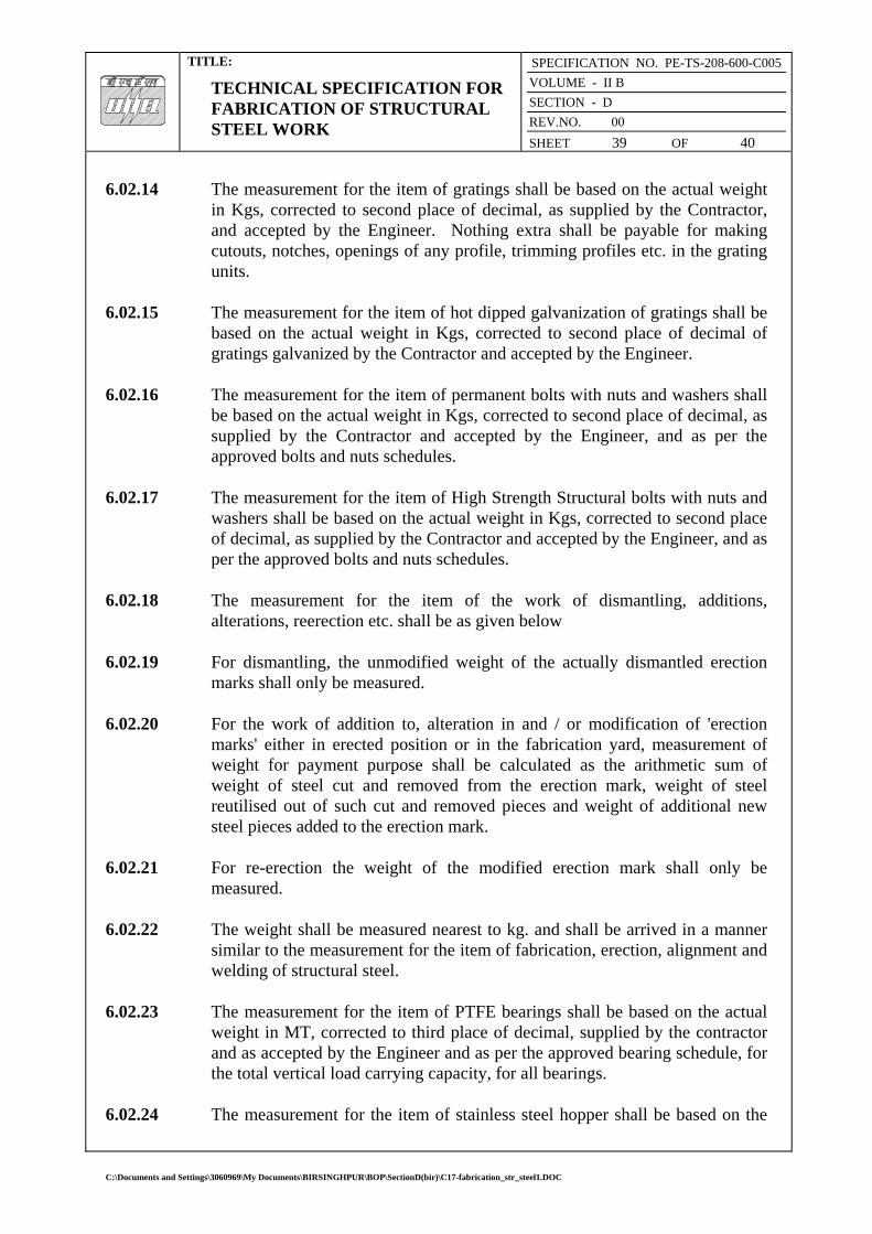
TITLE:
TECHNICAL SPECIFICATION FOR FABRICATION OF STRUCTURAL STEEL WORK
SPECIFICATION NO. PE-TS-208-600-C005
VOLUME - II B
SECTION - D
REV.NO. 00
SHEET 39 OF 40
6.02.14 The measurement for the item of gratings shall be based on the actual weight
in Kgs, corrected to second place of decimal, as supplied by the Contractor, and accepted by the Engineer. Nothing extra shall be payable for making cutouts, notches, openings of any profile, trimming profiles etc. in the grating units.
6.02.15 The measurement for the item of hot dipped galvanization of gratings shall be based on the actual weight in Kgs, corrected to second place of decimal of gratings galvanized by the Contractor and accepted by the Engineer.
6.02.16 The measurement for the item of permanent bolts with nuts and washers shall be based on the actual weight in Kgs, corrected to second place of decimal, as supplied by the Contractor and accepted by the Engineer, and as per the approved bolts and nuts schedules.
6.02.17 The measurement for the item of High Strength Structural bolts with nuts and washers shall be based on the actual weight in Kgs, corrected to second place of decimal, as supplied by the Contractor and accepted by the Engineer, and as per the approved bolts and nuts schedules.
6.02.18 The measurement for the item of the work of dismantling, additions, alterations, reerection etc. shall be as given below
6.02.19 For dismantling, the unmodified weight of the actually dismantled erection marks shall only be measured.
6.02.20 For the work of addition to, alteration in and / or modification of 'erection marks' either in erected position or in the fabrication yard, measurement of weight for payment purpose shall be calculated as the arithmetic sum of weight of steel cut and removed from the erection mark, weight of steel reutilised out of such cut and removed pieces and weight of additional new steel pieces added to the erection mark.
6.02.21 For re-erection the weight of the modified erection mark shall only be measured.
6.02.22 The weight shall be measured nearest to kg. and shall be arrived in a manner similar to the measurement for the item of fabrication, erection, alignment and welding of structural steel.
6.02.23 The measurement for the item of PTFE bearings shall be based on the actual weight in MT, corrected to third place of decimal, supplied by the contractor and as accepted by the Engineer and as per the approved bearing schedule, for the total vertical load carrying capacity, for all bearings.
6.02.24 The measurement for the item of stainless steel hopper shall be based on the
C:\Documents and Settings\3060969\My Documents\BIRSINGHPUR\BOP\SectionD(bir)\C17-fabrication_str_steel1.DOC

TITLE:
TECHNICAL SPECIFICATION FOR FABRICATION OF STRUCTURAL STEEL WORK
SPECIFICATION NO. PE-TS-208-600-C005
VOLUME - II B
SECTION - D
REV.NO. 00
SHEET 40 OF 40
actual finished weight of hopper weight in Kgs, corrected to second place of decimal. The hopper weight shall be arrived by multiplying of the inner surface area of the hopper with the unit weight of the hopper plate.
6.02.25 The measurement for the item of flexible open-ended bellows straps of neoprene shall be based in running meter, corrected to second place of decimal. Bellow Straps shall be supplied as per the requirement of the approved drawings. The measurement shall be done for the inner circumference of the bunker on which neoprene has been fixed and for the length supplied by the Contractor 'and as accepted by the Engineer.
6.02.26 The measurement for the item of Stainless Steel Hand Railing shall be based in Kgs corrected to second place of decimal. The weight shall also include the weight of Stainless Steel fasteners, Stainless Steel beading, Stainless Steel cleats etc. The weight shall be the finished weight of Hand Rail, as accepted by the Engineer.
C:\Documents and Settings\3060969\My Documents\BIRSINGHPUR\BOP\SectionD(bir)\C17-fabrication_str_steel1.DOC

TITLE:
TECHNICAL SPECIFICATION FOR ERECTION OF STRUCTURAL STEELWORK
SPECIFICATION NO. PE-TS-208-600-C005
VOLUME - II B
SECTION - D | SUB-SECTION – C18
REV.NO. 00
SHEET 1 OF 17
VOLUME: II B
SECTION - D
SUB-SECTION – C18
ERECTION OF STRUCTURAL STEELWORK
SPECIFICATION NO. PE-TS-208-600-C005
Bharat Heavy Electricals Limited Project Engineering Management
Power Sector, BHEL House Asian Games Village Complex
Siri Fort, New Delhi-110049
C:\Documents and Settings\3060969\My Documents\BIRSINGHPUR\BOP\SectionD(bir)\C18-erection_str_steel1.DOC

TITLE:
TECHNICAL SPECIFICATION FOR ERECTION OF STRUCTURAL STEELWORK
SPECIFICATION NO. PE-TS-208-600-C005
VOLUME - II B
SECTION - D | SUB-SECTION – C18
REV.NO. 00
SHEET 2 OF 17
C 0 N T E N T
CLAUSE NO. DESCRIPTION SHEET NO.
1.00.00 SCOPE 3 2.00.00 GENERAL 3 3.00.00 WORKMANSHIP 6 4.00.00 TESTING AND ACCEPTANCE CRITERIA 12 5.00.00 INFORMATION TO BE SUBMITTED 16
C:\Documents and Settings\3060969\My Documents\BIRSINGHPUR\BOP\SectionD(bir)\C18-erection_str_steel1.DOC
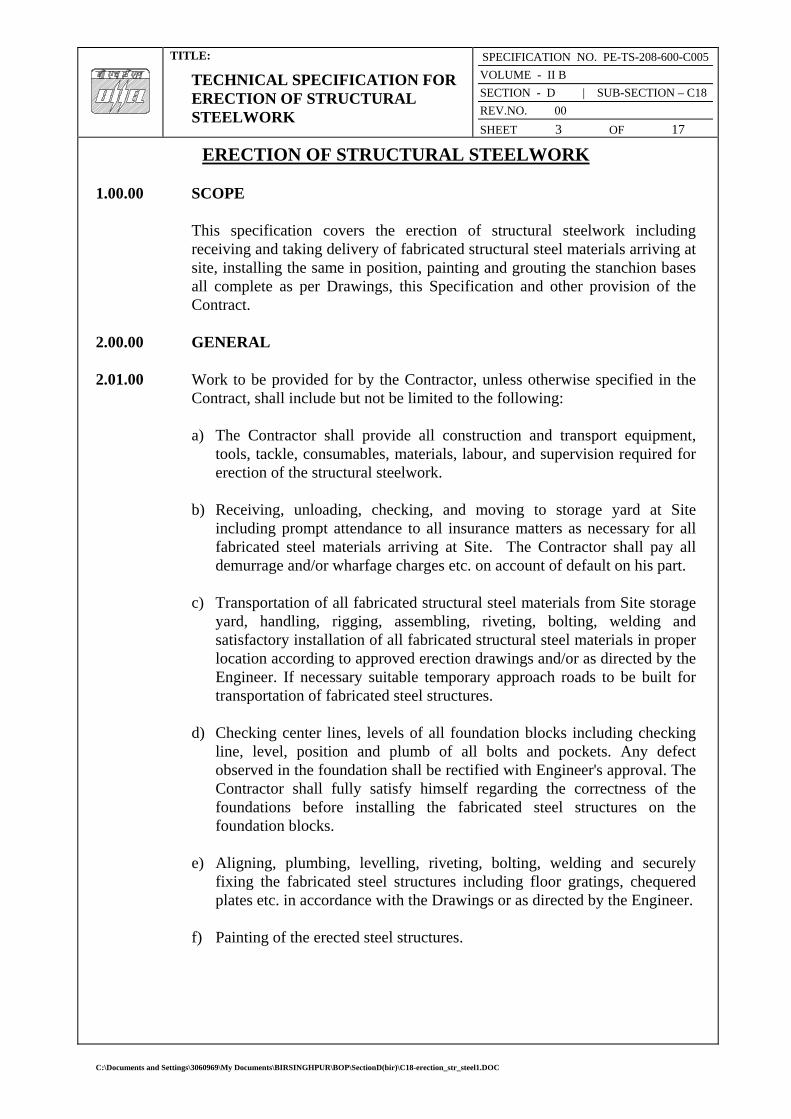
TITLE:
TECHNICAL SPECIFICATION FOR ERECTION OF STRUCTURAL STEELWORK
SPECIFICATION NO. PE-TS-208-600-C005
VOLUME - II B
SECTION - D | SUB-SECTION – C18
REV.NO. 00
SHEET 3 OF 17
ERECTION OF STRUCTURAL STEELWORK 1.00.00 SCOPE
This specification covers the erection of structural steelwork including
receiving and taking delivery of fabricated structural steel materials arriving at site, installing the same in position, painting and grouting the stanchion bases all complete as per Drawings, this Specification and other provision of the Contract.
2.00.00 GENERAL
2.01.00 Work to be provided for by the Contractor, unless otherwise specified in the Contract, shall include but not be limited to the following: a) The Contractor shall provide all construction and transport equipment,
tools, tackle, consumables, materials, labour, and supervision required for erection of the structural steelwork.
b) Receiving, unloading, checking, and moving to storage yard at Site
including prompt attendance to all insurance matters as necessary for all fabricated steel materials arriving at Site. The Contractor shall pay all demurrage and/or wharfage charges etc. on account of default on his part.
c) Transportation of all fabricated structural steel materials from Site storage
yard, handling, rigging, assembling, riveting, bolting, welding and satisfactory installation of all fabricated structural steel materials in proper location according to approved erection drawings and/or as directed by the Engineer. If necessary suitable temporary approach roads to be built for transportation of fabricated steel structures.
d) Checking center lines, levels of all foundation blocks including checking
line, level, position and plumb of all bolts and pockets. Any defect observed in the foundation shall be rectified with Engineer's approval. The Contractor shall fully satisfy himself regarding the correctness of the foundations before installing the fabricated steel structures on the foundation blocks.
e) Aligning, plumbing, levelling, riveting, bolting, welding and securely
fixing the fabricated steel structures including floor gratings, chequered plates etc. in accordance with the Drawings or as directed by the Engineer.
f) Painting of the erected steel structures.
C:\Documents and Settings\3060969\My Documents\BIRSINGHPUR\BOP\SectionD(bir)\C18-erection_str_steel1.DOC

TITLE:
TECHNICAL SPECIFICATION FOR ERECTION OF STRUCTURAL STEELWORK
SPECIFICATION NO. PE-TS-208-600-C005
VOLUME - II B
SECTION - D | SUB-SECTION – C18
REV.NO. 00
SHEET 4 OF 17
g) All minor modifications of the fabricated steel structures as directed by the Engineer including but not limited to the following:
i) Removal of bends, kinks, twists etc. for parts damaged during transport
and handling.
ii) Cutting, chipping, filling, grinding, etc. if required for preparation and finishing of site connections.
iii) Reaming of holes for use of higher size rivet or bolt if required. iv) Refabrication of parts damaged beyond repair during transport and
handling or refabrication of parts, which are incorrectly fabricated. v) Fabrication of parts omitted during fabrication by error, or
subsequently found necessary. vi) Drilling of holes which are either not drilled at all or are drilled in
incorrect location during fabrication. vii) Carry out tests in accordance with this specification.
2.02.00 Work by Others
No work under this Specification will be provided for by any agency other than the Contractor unless specifically mentioned elsewhere in the contract.
2.03.00 Codes and Standards All work under this Specification shall, unless specified otherwise, conform to the latest revisions and/or replacements of the following or any other Indian Standard Specification and codes of Practice of equivalent: IS: 800 - Code of practice for general construction in steel. IS: 456 - Code of practice for main or reinforced concrete.
2.04.00 Conformity with Designs The Contractor will erect the entire fabricated steel structure, align all the members, complete all field connections and grout the foundations all as per the provisions of this specification and the sequence and the design criteria laid down by the Engineer. All work shall conform to the provisions of this specification and /or instructions of the engineer. The testing and acceptance of the erected structures shall be in accordance with the provisions of this Specifications and/or the instructions o the Engineer.
2.05.00 Material
C:\Documents and Settings\3060969\My Documents\BIRSINGHPUR\BOP\SectionD(bir)\C18-erection_str_steel1.DOC

TITLE:
TECHNICAL SPECIFICATION FOR ERECTION OF STRUCTURAL STEELWORK
SPECIFICATION NO. PE-TS-208-600-C005
VOLUME - II B
SECTION - D | SUB-SECTION – C18
REV.NO. 00
SHEET 5 OF 17
2.05.01 General
All fabricated steel structures and connection materials shall be supplied by the Contractor to the site. The Contractor shall take delivery from railway wagons or trucks at site, and unload the materials and perform all formalities like checking of materials and attend to insurance matters in accordance with Sub-Clause 2.01.00 and as specified hereinbefore.
2.05.02 Materials to conform to Indian standards All materials required to be supplied by the Contractor under this contract shall conform to the relevant Indian Standard specifications.
2.06.00 Storage of Materials 2.06.01 General
All material shall be so stored as to prevent deterioration and to ensure the preservation of their quality and fitness for use in the works. Any material which has been deteriorated or damaged beyond repairs and has become unfit for use shall be removed immediately from the site, failing which, the engineer shall be at liberty to get the materials removed by agency and the cost incurred thereof shall be realised from the Contractor's dues.
2.06.02 Yard
The Contractor will have to establish a suitable yard in an approved location at site for storing the fabricated steel structures and other raw steel materials such as structural sections and plates as required. The yard shall have facilities like drainage, lighting, and suitable access for large cranes, trailers, and other heavy equipments. The yard shall be fenced all around with security arrangement and shall be of sufficiently large area to permit systematic storage of the fabricated steel structures without overcrowding and with suitable access for cranes, trailers and other equipment for use in erection work in proper sequence in accordance with the approved Programme of work. The Tenderer must visit the site prior to submission of his tender to acquaint himself with the availability of land and the development necessary by way of filling, drainage, access roads, fences, sheds etc. all of which shall be carried out by the Contractor at his own cost as directed by the Engineer.
2.06.03 Covered Store
All field connection materials, paints, cement etc. shall be stored on well designed racks and platforms off the ground in a properly covered store building to be built at the cost of the Contractor.
C:\Documents and Settings\3060969\My Documents\BIRSINGHPUR\BOP\SectionD(bir)\C18-erection_str_steel1.DOC

TITLE:
TECHNICAL SPECIFICATION FOR ERECTION OF STRUCTURAL STEELWORK
SPECIFICATION NO. PE-TS-208-600-C005
VOLUME - II B
SECTION - D | SUB-SECTION – C18
REV.NO. 00
SHEET 6 OF 17
2.07.00 Quality Control
The contractor shall establish and maintain quality control procedures for different items of work and materials as may be directed by the Engineer to assure compliance with the provisions of the Contract and shall submit the records of the same to the Engineer. The quality control operation shall include but not be limited to the Following items of work :
i) Erection: Lines, levels, grades, plumbs, joint characteristics including
tightness of bolts. ii) Grouting: Cleaning and roughness of foundation, quality of materials used
for grouting, admixtures, consistency, and strength of grout. iii) Painting: Preparation of surface for painting, quality of primers and paints,
thinners, application and uniformity of coats.
2.08.00 Taking Delivery The Contractor shall take delivery of fabricated structural steel and necessary connection materials from railhead/trucks as may be necessary and as directed by the Engineer. He shall check, unload; transport the materials to his stores for proper storing at his own cost. The Contractor shall submit claims to insurance or other authorities and pursue the same in case of loss or damage during transit and handling and all loss thereof shall be borne by him. The Contractor shall also take all precautions against damage of the materials in his custody after taking delivery and till the same are erected in place and accepted. The Contractor shall salvage, collect, and deliver all the packing materials to the Owner free of charge.
3.00.00 WORKMANSHIP
3.01.00 Erection
3.01.01 Plant and Equipment The suitability and adequacy of all erection tools and plant and equipment proposed to be used shall be thoroughly verified. They shall be efficient, dependable, in good working condition and shall have the approval of the Engineer.
3.01.02 Method and sequence of erection
The method and sequence of erection shall have the prior approval of the
C:\Documents and Settings\3060969\My Documents\BIRSINGHPUR\BOP\SectionD(bir)\C18-erection_str_steel1.DOC

TITLE:
TECHNICAL SPECIFICATION FOR ERECTION OF STRUCTURAL STEELWORK
SPECIFICATION NO. PE-TS-208-600-C005
VOLUME - II B
SECTION - D | SUB-SECTION – C18
REV.NO. 00
SHEET 7 OF 17
Engineer. The Contractor shall arrange for most economical method and sequence available to him consistent with the drawings and specifications and other relevant stipulations of the contract.
3.01.03 Temporary Bracing Unless adequate bracing is included as a part of the permanent framing, the erector during erecrtion shall install, free of cost to the Owne, temporary guys and bracings where needed to secure the framing against loads such as wind or seismic forces comparable in intensity to that for which the structure has been designed, acting upon exposed framing as well as loads due to erection equipment and erection operations. If additional temporary guys are required to resist wind or seismic forces acting upon components of the finished structure installed by others during the course of the erection of the steel framing, arrangement for their installation by the erector shall be made free of cost to the Owner. The requirement of temporary bracings and guys shall cease when the structural steel is once located, plumbed, levelled, aligned, and grouted within the tolerances permitted under the specification and guyed and braced to the satisfaction of the Engineer. The temporary guys, braces, false work, and cribbing shall not be the property of the Owner and they may be removed immediately upon completion of the steel erection.
3.01.04 Temporary Floors for Buildings
It shall be the responsibility of the Contractor to provide free of cost planking and to cover such floors during the work in progress as may be required by any Act of Parliament and/or bylaws of state, Municipal or other local authorities.
3.01.05 Setting Out Positioning and levelling of all steelwork, plumbing of stanchions and placing of every part of the structure with accuracy shall be in accordance with the approved Drawings and to the satisfaction of the Engineer. For heavy columns, etc. the Contractor shall set proper screed bars to maintain proper level. No extra payment shall be made for this. Each tier of column shall be plumbed and maintained in a true vertical position subject to the limits of tolerance under this Specification. No permanent field connections by riveting, bolting or shall be carried out until proper alignment and plumbing has been attained.
C:\Documents and Settings\3060969\My Documents\BIRSINGHPUR\BOP\SectionD(bir)\C18-erection_str_steel1.DOC

TITLE:
TECHNICAL SPECIFICATION FOR ERECTION OF STRUCTURAL STEELWORK
SPECIFICATION NO. PE-TS-208-600-C005
VOLUME - II B
SECTION - D | SUB-SECTION – C18
REV.NO. 00
SHEET 8 OF 17
3.01.06 Field Riveting All rivets shall be heated and driven with pneumatic tools. Hand passing or "throwing” of rivets are desirable. Any other method of conveying hot rivets from the furnace to the driving point must be approved by the engineer. No-cold rivets shall be driven. All other requirements of riveting including quality and acceptance criteria shall be in accordance with the relevant portions of the Specification for Fabrication of Structural Steelwork of the Project.
3.01.07 Field Bolting
All relevant Portions in respect of bolted construction of the Specification for Fabrication of Structural Steelwork applicable to the Project shall also be applicable for field bolting in addition to the following: Bolts shall be inserted in such a way so that they may remain in position under gravity even before fixing the nut. Bolted parts shall fit solidly together when assembled and shall not be separated by gaskets or any other interposed compressible materials. When assembled, all joint surfaces, including those adjacent to the washers shall be free of scales except tight mill scales. They shall be free of dirt, loose scales, burns, and other, defects that would prevent solid seating of the parts. Contact surfaces within friction type joints shall be free of oil, paint, lacquer, or galvanizing. All high tensile bolts shall be tightened to provide, when all fasteners in the joint are tight, the required minimum bolt tension by any of the following methods. a) Turn-of-nut Method
When the turn-of-nut method is used to provide the bolt tension, there shall first be enough bolts brought to a "snug tight” condition to ensure that the parts of the Joint are brought into good contact with each other. 'Snug tight" is defined as the tightness attained by a few impacts of an impact wrench or the full effort of a man using an ordinary spud wrench. Following this initial operation, bolts shall be placed in any remaining holes in the connection and brought to snug tightness. All bolts in the joint shall then be tightened additionally by the applicable amount of nut rotation specified in Table-I with tightening progressing systematically from the most rigid part of the joint to its free edges. During this operation there shall be no rotation of the part not turned by the wrench.
TABLE-I
Bolts length not Bolt length Remarks exceeding 8 times exceeding 8 times
C:\Documents and Settings\3060969\My Documents\BIRSINGHPUR\BOP\SectionD(bir)\C18-erection_str_steel1.DOC
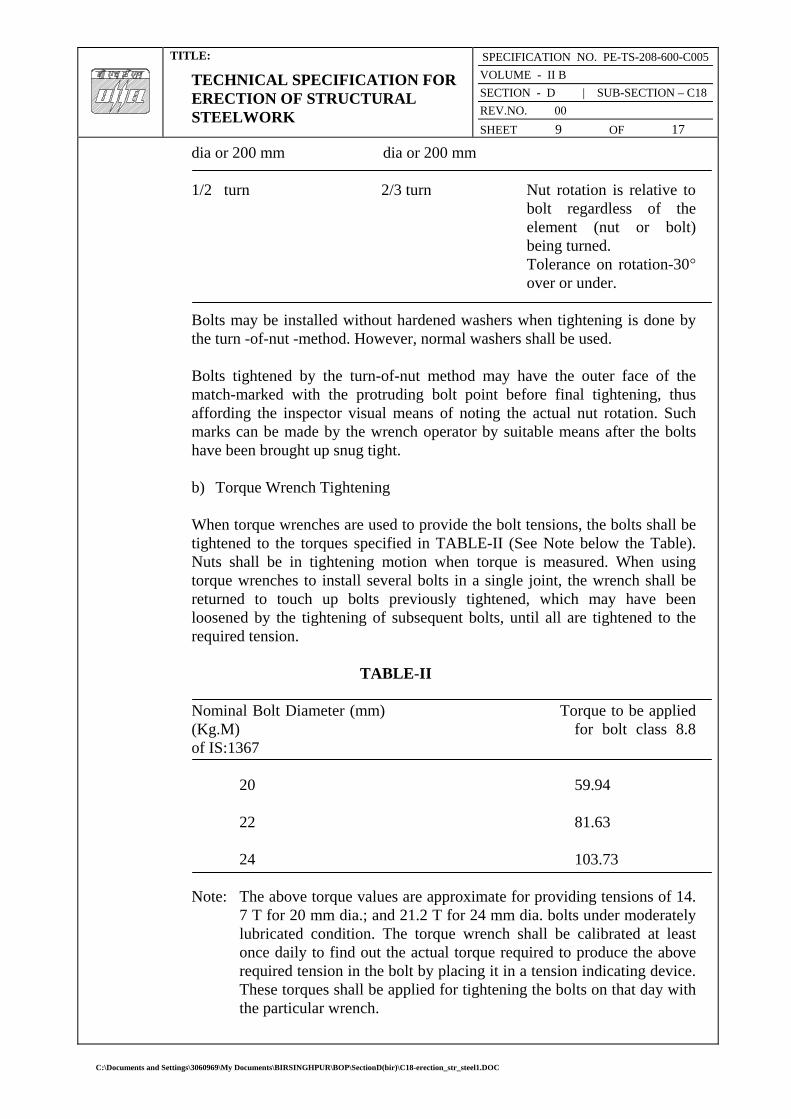
TITLE:
TECHNICAL SPECIFICATION FOR ERECTION OF STRUCTURAL STEELWORK
SPECIFICATION NO. PE-TS-208-600-C005
VOLUME - II B
SECTION - D | SUB-SECTION – C18
REV.NO. 00
SHEET 9 OF 17
dia or 200 mm dia or 200 mm
1/2 turn 2/3 turn Nut rotation is relative to bolt regardless of the element (nut or bolt) being turned.
Tolerance on rotation-30° over or under.
Bolts may be installed without hardened washers when tightening is done by the turn -of-nut -method. However, normal washers shall be used. Bolts tightened by the turn-of-nut method may have the outer face of the match-marked with the protruding bolt point before final tightening, thus affording the inspector visual means of noting the actual nut rotation. Such marks can be made by the wrench operator by suitable means after the bolts have been brought up snug tight. b) Torque Wrench Tightening When torque wrenches are used to provide the bolt tensions, the bolts shall be tightened to the torques specified in TABLE-II (See Note below the Table). Nuts shall be in tightening motion when torque is measured. When using torque wrenches to install several bolts in a single joint, the wrench shall be returned to touch up bolts previously tightened, which may have been loosened by the tightening of subsequent bolts, until all are tightened to the required tension.
TABLE-II Nominal Bolt Diameter (mm) Torque to be applied (Kg.M) for bolt class 8.8 of IS:1367 20 59.94 22 81.63 24 103.73 Note: The above torque values are approximate for providing tensions of 14.
7 T for 20 mm dia.; and 21.2 T for 24 mm dia. bolts under moderately lubricated condition. The torque wrench shall be calibrated at least once daily to find out the actual torque required to produce the above required tension in the bolt by placing it in a tension indicating device. These torques shall be applied for tightening the bolts on that day with the particular wrench.
C:\Documents and Settings\3060969\My Documents\BIRSINGHPUR\BOP\SectionD(bir)\C18-erection_str_steel1.DOC

TITLE:
TECHNICAL SPECIFICATION FOR ERECTION OF STRUCTURAL STEELWORK
SPECIFICATION NO. PE-TS-208-600-C005
VOLUME - II B
SECTION - D | SUB-SECTION – C18
REV.NO. 00
SHEET 10 OF 17
In either of the above two methods, if required, for bolt entering and wrench operation clearances, tightening may be done by turning the bolt while the nut is prevented from rotating. Impact wrenches if used shall be of adequate capacity and sufficiently supplied with air to perform the required tightening of each bolt in approximately ten seconds. Holes for turned bolts to be inserted in the field shall be reamed in the field. All drilling and reaming for turned bolts shall be done only after the parts to be connected are assembled. Tolerances applicable in the fit of the bolts shall be in accordance with relevant Indian Standard Specifications. All other requirements regarding assembly and bolt tightening shall be in accordance with this sub clause.
3.01.08 Field Welding
All field assembly and welding shall be carried out in accordance with the requirements of the specification for fabrication work applicable to the project, excepting such provisions therein which manifestly apply to shop conditions only. Where the fabricated structural steel members have been delivered painted, the paint shall be removed before field welding for a distance of at least 50 mm on either side of the joints.
3.01.09 Holes, Cutting and Fitting
No cutting of sections, flanges, webs, cleats, rivets, bolts, welds etc. shall be done unless specifically approved and /or instructed by the Engineer. The erector shall not cut, drill, or otherwise alter the work of other trades, unless such work is clearly specified in the Contract or directed by the Engineer. Wherever such work is obtain specified the Contractor shall obtain complete information as to size, location and number of alterations prior to carrying out any work. The Contractor shall not be entitled for any payment on account of any such work.
3.02.00 Drifting Correction of minor misfits and reasonable amount of reaming and cutting of excess stock from rivets will be considered as permissible. For this, light drifting may be used to draw holes together and drills shall be used to enlarge holes as necessary to make connections. Reaming, that weakens the member or makes it impossible to fill the holes properly or to adjust accurately after reaming, shall not be allowed. Any error in shop work which prevents the proper assembling and fitting of parts by moderate use of drift pins and reamers shall immediately be called to the attention of the Engineer and approval of the method of correction
C:\Documents and Settings\3060969\My Documents\BIRSINGHPUR\BOP\SectionD(bir)\C18-erection_str_steel1.DOC

TITLE:
TECHNICAL SPECIFICATION FOR ERECTION OF STRUCTURAL STEELWORK
SPECIFICATION NO. PE-TS-208-600-C005
VOLUME - II B
SECTION - D | SUB-SECTION – C18
REV.NO. 00
SHEET 11 OF 17
obtained. The use of gas cutting torches at erection site is prohibited.
3.03.00 Grouting of stanchion bases and bearings of beams and girders on stone, brick or concrete (Plain or reinforced)
Grouting shall be carried out with Ordinary Cement grout as described below: The mix shall be one (1) part cement and one (1) part sand and just enough water to make it workable. The positions to be grouted shall be cleaned thoroughly with compressed air jet and wetted with water and any accumulated water shall be removed. These shall be placed under expert supervision, taking care to avoid air locks. Edges shall be finished properly. If the thickness of grout is 25 mm or more, two (2) parts of 6 mm down graded stone chips may be added to the above noted cement-sand grout mix, if required, by the Engineer or shown on the drawings. No grouting shall be carried out until a sufficient number of bottom lengths of stanchions have been properly lined, leveled, and plumbed and sufficient floor beams are tied in position. Whatever method of grouting is employed, the operation shall not be carried out until the steelwork has been finally levelled and plumbed, the stanchion bases being supported meanwhile by steel wedges, and immediately before grouting, the space under steel shall be thoroughly cleaned. If required by the Engineer, certain admixtures like aluminium powder, “ironite” or equivalent, may be required to be added to the grout to enhance certain desirable properties of the grout. Approved non-shrink pre-mixed grout having required flowability and compressive strength may also be used with Engineer's approval.
3.04.00 Painting after Erection Field painting shall only be done after the structure is erected, levelled, plumbed, aligned and grouted in its final position, tested and accepted by the Engineer. Normally, final painting shall be done only after the floor slabs are concreted and masonry walls are built. However, touch up painting, making good any damaged shop painting and completing any unfinished portion of the shop coat shall be carried out by the Contractor free of cost to the Owner. The materials and specification for such painting in the field shall be in accordance with the requirements of the specification for fabrication of structural steelwork applicable for the project. Painting shall not be done in frosty or foggy weather or when humidity is such as to cause condensation on the surfaces to be painted. Before painting of steel, which is delivered unpainted, is commenced, all surfaces to be painted shall be dried and thoroughly cleaned from all loose scale and rust.
C:\Documents and Settings\3060969\My Documents\BIRSINGHPUR\BOP\SectionD(bir)\C18-erection_str_steel1.DOC

TITLE:
TECHNICAL SPECIFICATION FOR ERECTION OF STRUCTURAL STEELWORK
SPECIFICATION NO. PE-TS-208-600-C005
VOLUME - II B
SECTION - D | SUB-SECTION – C18
REV.NO. 00
SHEET 12 OF 17
All field rivets, bolts, welds, and abrasions to the shop coat shall be spot painted with the same paint used for the shop coat. Where specified, surfaces, which will be in contact after site assembling, shall receive a coat of paint (in addition to the shop coat, if any) and shall be brought together while the paint is still wet. Surface, which will be inaccessible after field assembly shall receive the full, specified protective treatment before Bolts and fabricated steel members who are galvanized or otherwise treated and steel members to be encased shall not be painted. The final painting shall be of tow coats of Synthetics Enamel painting or Aluminium paint of approved manufacture as per the approved “Schedule of Painting”. The shades shall also be as per the approved schedule. Synthetic enamel paint shall conform to IS: 2932.
3.05.00 Final cleaning up Upon completion of erection and before final acceptance of the work by the Engineer, the contractor shall remove free of cost all false work, rubbish and all Temporary Works resulting in connection with the performance of his work.
4.00.00 TESTING AND ACCEPTANCE CRITERIA 4.01.00 General
Loading tests shall be carried out on erected structures, if required by the Engineer, to check adequacy of fabrication and/or erection. Any structure or a part thereof found to be unsuitable for acceptance as a result of the test shall have to be dismantled and replaced with suitable member as per the Contract and no payment towards the cost of the dismantled portion and any connected work shall be made to the contractor. In course of dismantling, if any damage is done to any other parts of the structure or to any fixtures, the same shall be made good free of cost by the Contractor, to the satisfaction of the Engineer. The Cost of the tests specified hereinafter shall be borne by the Owner; but if the structure fails to pass the tests, the cost of the tests shall be recovered from the Contractor. Any extra claim due to loss of time, idle labour, etc. arising out of these testing operations shall not be entertained, however, only reasonable and appropriate time extensions will be allowed. The structure or structural member under consideration shall be loaded with its actual dead load for as long a time as possible before testing and the tests shall be conducted as indicated in the following sub-clauses 4.01.01, 4.01.02 and 4.01.03. The method of testing and application of loading shall be as approved by the Engineer.
C:\Documents and Settings\3060969\My Documents\BIRSINGHPUR\BOP\SectionD(bir)\C18-erection_str_steel1.DOC

TITLE:
TECHNICAL SPECIFICATION FOR ERECTION OF STRUCTURAL STEELWORK
SPECIFICATION NO. PE-TS-208-600-C005
VOLUME - II B
SECTION - D | SUB-SECTION – C18
REV.NO. 00
SHEET 13 OF 17
4.01.01 Stiffness Test
In this test, the structure or member shall be subjected, addition to its actual dead load, to a test load equal to 1.5 times the specified superimposed load, and this loading shall be maintained for 24 hours. The maximum deflection attained during the test shall be within the permissible limit. If, after removal of the test load, the member or structure does not show a recovery of at least 80 per cent of the maximum strain or deflection shown during 24 hours under load, the test shall be repeated. The structure or member shall be considered to have sufficient stiffness, provided that the recovery after this second test is not less than 90 per cent of the maximum increase in strain or deflection recorded during the second test.
4.01.02 Strength Test
The structure or structural member under consideration shall be subjected, in addition to its actual dead load, to a test load equal to the sum of the dead load and twice the specified superimposed load, and this load shall be maintained for 24 hours. In the case of wind load, a load corresponding to twice the specified wind load shall be applied and maintained for 24 hours, either with or without the vertical test load for more severe condition in the member under consideration or the structure as a whole. Complete tests under both conditions may be necessary to verify the strength of the structure. The structure shall be deemed to have adequate strength if, during the test, no part fails and if on the removal of the test load, the structure shows a recovery of at least 20 per cent of the maximum deflection or strain recorded during the 24 hours under load.
4.01.03 Structure of same design Where several structures are built to the same design and it is considered unnecessary to test all of them, one structure, as a prototype, shall be fully tested, as described in previous Sub-clauses, but in addition, during the first application of the test load, particular note shall be taken of the strain or deflection when the test load 1.5 times the specified superimposed load has been maintained for 24 hours. This information is required as a basis of comparison in any check test carried out on samples of the structure. When a structure of the same type is selected for a check test, it shall be subjected, in addition to its actual dead load, to a superimposed test load, equal to 1.5 time the specified live load, in a manner and to an extent prescribed by the Engineer. This load shall be maintained for 24 hours, during which time, the maximum deflection shall be recorded. The check test shall be considered satisfactory, provided that the maximum strain or deflection recorded in the check test does not exceed by more than 20% of the maximum
C:\Documents and Settings\3060969\My Documents\BIRSINGHPUR\BOP\SectionD(bir)\C18-erection_str_steel1.DOC
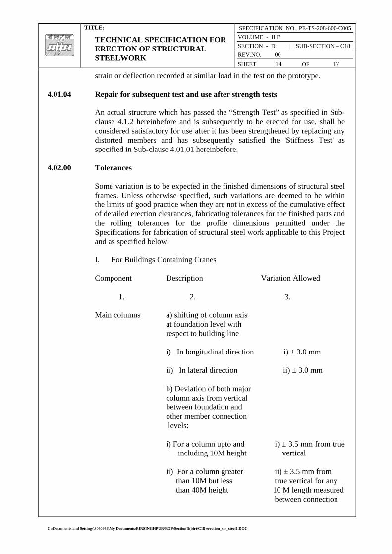
TITLE:
TECHNICAL SPECIFICATION FOR ERECTION OF STRUCTURAL STEELWORK
SPECIFICATION NO. PE-TS-208-600-C005
VOLUME - II B
SECTION - D | SUB-SECTION – C18
REV.NO. 00
SHEET 14 OF 17
strain or deflection recorded at similar load in the test on the prototype.
4.01.04 Repair for subsequent test and use after strength tests
An actual structure which has passed the “Strength Test” as specified in Sub-clause 4.1.2 hereinbefore and is subsequently to be erected for use, shall be considered satisfactory for use after it has been strengthened by replacing any distorted members and has subsequently satisfied the 'Stiffness Test' as specified in Sub-clause 4.01.01 hereinbefore.
4.02.00 Tolerances
Some variation is to be expected in the finished dimensions of structural steel frames. Unless otherwise specified, such variations are deemed to be within the limits of good practice when they are not in excess of the cumulative effect of detailed erection clearances, fabricating tolerances for the finished parts and the rolling tolerances for the profile dimensions permitted under the Specifications for fabrication of structural steel work applicable to this Project and as specified below: I. For Buildings Containing Cranes Component Description Variation Allowed
1. 2. 3. Main columns a) shifting of column axis at foundation level with respect to building line
i) In longitudinal direction i) ± 3.0 mm
ii) In lateral direction ii) ± 3.0 mm
b) Deviation of both major column axis from vertical between foundation and other member connection levels: i) For a column upto and i) ± 3.5 mm from true
including 10M height vertical ii) For a column greater ii) ± 3.5 mm from than 10M but less true vertical for any
than 40M height 10 M length measured between connection
C:\Documents and Settings\3060969\My Documents\BIRSINGHPUR\BOP\SectionD(bir)\C18-erection_str_steel1.DOC

TITLE:
TECHNICAL SPECIFICATION FOR ERECTION OF STRUCTURAL STEELWORK
SPECIFICATION NO. PE-TS-208-600-C005
VOLUME - II B
SECTION - D | SUB-SECTION – C18
REV.NO. 00
SHEET 15 OF 17
levels, but not more than ±7 mm per 30m length.
c) For adjacent pairs of columns ± 9.0 mm on true across the width of the building span. prior to placing of truss
d) For any individual column ± 3.0 mm deviation of any bearing or resting level from levels shown on drawings.
e) For adjacent pairs of columns 3.0 mm either across the width of building or longitudinally level difference allowed between bearing or seating
Trusses a) Deviation at centre of span 1/1500 of the span or
of upper chord member from greater than 10mm vertical plane running through whichever is the least. centre of bottom chord. Trusses b) Lateral displacement of 1/250 of depth top chord at center of of truss or 20 mm span from vertical plane which ever is the - running through center of least. supports. Crane Cirders a) Difference in levels of crane rail measured between adjacent columns. 2.0 mm.
b) Deviation to crane rail- ± 3.0 mm gauge
c) Relative shifting of ends 1.0 mm. of adjacent crane rail in plan and elevation after thermite welding.
d) Deviation of crane rail axis ± 3.5 mm from centre line of web.
Setting of At the time of setting of Expansion the expansion gaps, due
C:\Documents and Settings\3060969\My Documents\BIRSINGHPUR\BOP\SectionD(bir)\C18-erection_str_steel1.DOC

TITLE:
TECHNICAL SPECIFICATION FOR ERECTION OF STRUCTURAL STEELWORK
SPECIFICATION NO. PE-TS-208-600-C005
VOLUME - II B
SECTION - D | SUB-SECTION – C18
REV.NO. 00
SHEET 16 OF 17
gaps regard shall be taken of the ambient temperature above or below 30°C. The coefficient of expansion or contraction shall be taken as 0.000012
per °C per unit length. iv) For Building without Cranes The maximum tolerances for line and level of the steel work shall be ±3.0 mm on any part of the structure. The structure shall not be Out of Plumb more than 3.5 mm on each lox section of height and not more than 7.0 mm per 30 m section. These tolerances shall apply to all parts of the structure unless the drawings issued for erection purposes state otherwise.
4.03.00 Acceptance Structures and members have passed the tests and conform to all requirements specified in the foregoing Sub-clause 4.01.00, 4.01.01, 4.01.02, 4.01.03 and 4.01.04 and other applicable provisions of this specification and are within the limits of tolerances specified in Sub-clause 4.02.00 and/or otherwise approved by the Engineer shall be treated as approved and accepted for the purpose of fulfillment of the provisions of this contract.
5.00.00 INFORMATION TO BE SUBMITTED
5.01.00 Before Tender
5.01.01 Tentative Programme The Tenderer shall submit a tentative programme based on the information available in the Tender Document and visit to site indicating the structure-wise erection schedule proposed to be maintained by the Contractor to complete the job in time in accordance with the Contract.
5.01.02 Constructional Plant and Equipment, Tools, Temporary works & manpower A
detailed list Of all constructional plant and equipment like cranes, derricks, winches, welding sets, erection tools etc. along with their make, model, present condition and location available with the Tenderer which he will be able to employ on the job to maintain the progress of work in accordance with the Contract shall be submitted along with the Tender. The total number of each category of experienced personnel like fitters, welders, riggers etc. that he will be able to employ on the job shall also be indicated.
5.01.03 Erection Yard
C:\Documents and Settings\3060969\My Documents\BIRSINGHPUR\BOP\SectionD(bir)\C18-erection_str_steel1.DOC

TITLE:
TECHNICAL SPECIFICATION FOR ERECTION OF STRUCTURAL STEELWORK
SPECIFICATION NO. PE-TS-208-600-C005
VOLUME - II B
SECTION - D | SUB-SECTION – C18
REV.NO. 00
SHEET 17 OF 17
A site plan showing the layout and location of the erection yard proposed to be established by the tenderer shall also be attached with the tender indicating the storage space for fabricated steel materials, site-fabrication and repair shop, covered stores, offices, locations of erection equipments and other facilities. The Engineer shall have the right to modify the arrangement and location of the proposed yard to suit site conditions and the Contractor shall comply with the same without any claim whatsoever.
5.02.00 After award of the Contract After award of the contract, the Contractor shall submit the following:
5.02.01 Detailed Programme
The Contractor shall submit a detailed erection programme within a month of the award of the Contract for completion of the work in time in accordance with the Contract. This will show the target programme, with details of erection proposed to be carried out in each fortnight, details of major equipment required, and an assessment of required strength of various categories of workers in a proforma approved by the Engineer.
5.02.02 Fortnightly Progress Report
The Contractor shall submit fortnightly progress reports in triplicate to the Engineer showing along with necessary photographs, 125 mm x 90 mm size, and all details of actual achievements against the target programme specified in Sub-clause 5.02.01 above. Any shortfall in the achievement in a particular fortnight must be made up within the next fortnight. Along with this report, the Contractor shall also furnish details of fabricated materials in hand at site and the strength of his workers.
C:\Documents and Settings\3060969\My Documents\BIRSINGHPUR\BOP\SectionD(bir)\C18-erection_str_steel1.DOC
TITLE:
TECHNICAL SPECIFICATION FOR ROOF DECKING
SPECIFICATION NO. PE-TS-208-600-C005
VOLUME - II B
SECTION - D | SUB-SECTION – C19
REV.NO. 00
SHEET 1 OF 7
VOLUME: II B
SECTION - D
SUB-SECTION – C19
ROOF DECKING
SPECIFICATION NO. PE-TS-208-600-C005
Bharat Heavy Electricals Limited Project Engineering Management
Power Sector, BHEL House Asian Games Village Complex
Siri Fort, New Delhi-110049
C:\Documents and Settings\3060969\My Documents\BIRSINGHPUR\BOP\SectionD(bir)\C19-roof_decking1.DOC

TITLE:
TECHNICAL SPECIFICATION FOR ROOF DECKING
SPECIFICATION NO. PE-TS-208-600-C005
VOLUME - II B
SECTION - D | SUB-SECTION – C19
REV.NO. 00
SHEET 2 OF 7
C 0 N T E N T
CLAUSE NO. DESCRIPTION SHEET NO.
1.00.00 SCOPE 3 2.00.00 MATERIALS 3 3.00.00 INSTALLATION 4 4.00.00 ACCEPTANCE CRITERIA 6 5.00.00 IS CODES 6 6.00.00 RATES AND MEASUREMENTS 7
C:\Documents and Settings\3060969\My Documents\BIRSINGHPUR\BOP\SectionD(bir)\C19-roof_decking1.DOC
TITLE:
TECHNICAL SPECIFICATION FOR ROOF DECKING
SPECIFICATION NO. PE-TS-208-600-C005
VOLUME - II B
SECTION - D | SUB-SECTION – C19
REV.NO. 00
SHEET 3 OF 7
ROOF DECKING 1.00.00 Scope This section of the specification covers the supply, fabrication and erection of
profiled light gauge Metal Decks (coated and painted) as roof decking to the main plant building and any other area as indicated in the drawings.
2.00.00 Material 2.01.01 Roof of main plant TG and Deareator bay and bunker building consists of
permanently colour coated (on exposed face) galvanized M.S. trough metal sheet decking plate of approved colour over roof purlins for In-situ roof slab as per IS: 14246 and conform to class 3. Thickness of deck plate shall be minimum 0.8mm and minimum trough depth of 44 mm and centre to centre of the valley shall be 130mm with minimum yield strength of 250 Mpa. Silicon modified polyester paint shall be used for permanent coating over galvanized surface with minimum rate of galvanization 275 gm/sqm. DFT of permanent colour coating shall be 20 microns. It shall serve as permanent shuttering for cast-in-situ roof slab. It should have adequate strength to support weight of green concrete and imposed load during construction. The thickness of the deck plate shall however be designed suitably according to the spacing of roof purlins.
3.00.00 INSTALLATION
The Contractor shall furnish all labour, equipment and materials as required for the design, fabrication, coating, erection and fixing of the decking over purlins, painting and for the complete performance of the work in accordance with the construction drawings and as described herein.
The description, which follows, gives a general indication of the nature and extent of the work but is not necessarily exhaustive and does not purport to cover all the details/operations which will be necessary in order to carry out the work.
3.01.00 Detailed Design of Roof Decking The Contractor, in conjunction with the manufacturer, shall be responsible for the detailing of
the profiled decking, fittings and fixtures and shall submit with his tender particulars of the proposed manufacturer and of the particular product proposed for use. The detailing is to be based on typical details furnished by the Engineer. The Contractor shall submit to the Engineer, two copies of the general arrangement and detailed working drawings for the proposed design, together with all calculations necessary to verify the adequacy and completeness of the design & detailing of decking sheets, fixtures, flashings
C:\Documents and Settings\3060969\My Documents\BIRSINGHPUR\BOP\SectionD(bir)\C19-roof_decking1.DOC

TITLE:
TECHNICAL SPECIFICATION FOR ROOF DECKING
SPECIFICATION NO. PE-TS-208-600-C005
VOLUME - II B
SECTION - D | SUB-SECTION – C19
REV.NO. 00
SHEET 4 OF 7
and trims. After approval he shall supply further eight copies.
The Engineer will verify the correct interpretation of his requirements but may not necessarily check the design and details, and the Contractor shall be entirely responsible for the accuracy of the drawings and the correctness of the design and the suitability of the details. Manufacture of roof decking sheets shall not commence until the necessary approval of the Engineer has been obtained.
3.02.00 Erection & Fixing 3.02.01 Sequence of Manufacture/Erection Cutting Schedules, delivery to site and stacking arrangements in store shall
ensure that sheets are erected in a sequence which follows that for the manufacture. The decking sheets shall be erected using an arrangement of sheets and joints to conform with the requirements of this specification. Decking erection for each elevation or feature shall commence at one end only and proceed towards the other end, in order to ensure tight fitting laps.
3.02.02 Position and Location of Laps Side and end laps of roof decking sheets shall be located and positioned in
such a manner as to provide the maximum weather protection taking into account the direction of the prevailing wind.
The lines formed by horizontal laps and fixing shall where possible, be
continuous and coincide with the edges of large openings in the roof. 3.02.03 Alignment of Sheets and Fixings All roof decking sheets shall be fixed plumb and level with all fixings evenly
spaced and accurately lined. All dirt and grease shall be removed from the surfaces of the sheets as the work proceeds.
3.02.04 Site Cutting Approval must be obtained before the roof decking sheets are cut at site.
Generally cutting of sheets to length will not be permitted, only special cutting and trimming for small openings shall allowed. Where possible, site cut edges shall be concealed at laps.
3.02.05 Damaged Sheets Distorted, blemished or water stained sheets and any other fittings shall not be
used. 3.02.06 Laps
C:\Documents and Settings\3060969\My Documents\BIRSINGHPUR\BOP\SectionD(bir)\C19-roof_decking1.DOC

TITLE:
TECHNICAL SPECIFICATION FOR ROOF DECKING
SPECIFICATION NO. PE-TS-208-600-C005
VOLUME - II B
SECTION - D | SUB-SECTION – C19
REV.NO. 00
SHEET 5 OF 7
End laps and side laps to roof decking sheets shall be sufficiently large to
ensure that the decking complies with the weather tightness and other requirements of this specification. The length of each decking sheet shall be adjusted so that the end laps shall bear on the purlins. In no case, end laps shall not be less than 150 mm and side laps shall not be less than 53 mm.
3.02.07 End Lap Fixings End lap fixings shall be located at least 25 mm from the end of each sheet. 3.02.08 Side Lap Fixings The spacing of side lap fixings shall ensure compliance with this specification
regarding tightness. The spacing of these fixing screws shall not exceed 500mm. The fixing shall be located in the bottom flat of the corrugation.
3.02.09 Holes Holes in MS decking sheets shall be punched. In case holes are drilled holes,
it is to be ensured that the holes do not go oversize due to the small thickness of the sheeting. All drilling swarf shall be removed from the surfaces of decking, supporting steel work, purlins etc.
3.02.10 Location and Spacing of Fixings Fixings shall be accurately located in position in the centre of the corrugations
to ensure that the heads of bolts, nuts and washers bear squarely down on the surface of the sheeting and are not located at the edge or on the joints in supporting purlins.
3.02.11 Fixings The tenderer shall submit with his tender details of the proposed method for
securing the roofing sheets to the metal purlins. The roof decking sheets are to be fixed to the roof purlins with hex washer head white zinc plated heat treated carbon steel self drilling / self tapping screws of minimum thread diameter of 5.6mm. These self drilling screws shall be drilled through the roofing sheets and purlins supporting the roofing sheets. These purlins shall be suitably spaced as per the requirement of roofing sheets and the roofing sheets shall not sag more than span/250 for the loads likely to be imposed during concreting and in future. The self-drilling screws are to be spaced at a maximum distance of 390mm centre to centre along the length of the purlins and top chord of truss. The screws are to be located preferably in the valley only and shall be installed in accordance with the manufacturer’s recommendations using tools approved by the manufacturer which do not damage the coating of the decking sheets.
C:\Documents and Settings\3060969\My Documents\BIRSINGHPUR\BOP\SectionD(bir)\C19-roof_decking1.DOC

TITLE:
TECHNICAL SPECIFICATION FOR ROOF DECKING
SPECIFICATION NO. PE-TS-208-600-C005
VOLUME - II B
SECTION - D | SUB-SECTION – C19
REV.NO. 00
SHEET 6 OF 7
3.03.00 Protection during Construction Precautions shall be taken during the erection of the roof decking to ensure
that partially erected decking are protected during inclement weather and damage at all times.
3.04.00 Damage
Any damage to coating & primer during transportation is to redone with the similar type of coating as per the manufacturer’s specification at no extra cost to the Owner.
4.00.00 Acceptance Criteria The installation shall present a neat appearance and shall be checked for water
tightness. The following shall be checked : a) Side and end laps b) Absence of damage in the sheeting. c) Conformity of fixings with the approved design. 5.00.00 IS Codes All work shall be carried out as per this specification and shall conform to the
latest revision and/or replacements of the following or any other Indian Standard (IS) Codes, unless specified otherwise. In case any particular aspect of work is not specifically covered by Indian Standard Codes, any other standard practice, as may be specified by the Engineer, shall be followed.
IS : 513 - Specification for cold rolled carbon steel sheets. IS : 3618 - Specification for phosphate treatment of iron and steel for
protection against corrosion.
IS : 4431 - Specification for carbon & carbon manganese free cutting steel.
IS : 1573 - Electroplated Coatings of zinc on iron and steel. 6.00.0 RATES AND MEASUREMENTS 6.01.00 Rates
C:\Documents and Settings\3060969\My Documents\BIRSINGHPUR\BOP\SectionD(bir)\C19-roof_decking1.DOC
TITLE:
TECHNICAL SPECIFICATION FOR ROOF DECKING
SPECIFICATION NO. PE-TS-208-600-C005
VOLUME - II B
SECTION - D | SUB-SECTION – C19
REV.NO. 00
SHEET 7 OF 7
Rates shall be unit rate for complete item described in the Schedule of Items
and shall include all wastage. 6.02.00 Method of Measurement Roofing shall be measured for net area of the work done. Profiled
sheeting (coated & painted) shall be measured in plan area of sheets and not girthed. No deduction shall be made for openings measuring up to 0.1 sq.m. in area. No extra shall be paid for extra labour in cutting and for wastage etc. in making opening and cutting to size.
No payments shall be made for laps.
C:\Documents and Settings\3060969\My Documents\BIRSINGHPUR\BOP\SectionD(bir)\C19-roof_decking1.DOC

TITLE:
TECHNICAL SPECIFICATION FOR FALSE FLOORING
SPECIFICATION NO. PE-TS-208-600-C005
VOLUME - II B
SECTION - D | SUB-SECTION – C20
REV.NO. 00
SHEET 1 OF 6
VOLUME: II B
SECTION - D
SUB-SECTION – C20
FALSE FLOORING
SPECIFICATION NO. PE-TS-208-600-C005
Bharat Heavy Electricals Limited Project Engineering Management
Power Sector, BHEL House Asian Games Village Complex
Siri Fort, New Delhi-110049
C:\Documents and Settings\3060969\My Documents\BIRSINGHPUR\BOP\SectionD(bir)\C20-false_flooring1.DOC

TITLE:
TECHNICAL SPECIFICATION FOR FALSE FLOORING
SPECIFICATION NO. PE-TS-208-600-C005
VOLUME - II B
SECTION - D | SUB-SECTION – C20
REV.NO. 00
SHEET 2 OF 6
C 0 N T E N T
CLAUSE NO. DESCRIPTION SHEET NO.
1.00.00 GENERAL 3 2.00.00 MATERIALS 3 3.00.00 INSTALLATION 4 4.00.00 ACCEPTANCE CRITERIA 5 5.00.00 IS CODES 6 6.00.00 RATES AND MEASUREMENTS 6
C:\Documents and Settings\3060969\My Documents\BIRSINGHPUR\BOP\SectionD(bir)\C20-false_flooring1.DOC

TITLE:
TECHNICAL SPECIFICATION FOR FALSE FLOORING
SPECIFICATION NO. PE-TS-208-600-C005
VOLUME - II B
SECTION - D | SUB-SECTION – C20
REV.NO. 00
SHEET 3 OF 6
FALSE FLOORING 1.00.00 General
This section of the specification covers the supply, fabrication and installation of false flooring system having PVC top finish particle board, GI supporting system, painting etc. as per schedule of items in the main plant building and any other area as indicated in the drawings.
The scope of contractor covers supply of all materials, fabrication & installation works required to be carried out for completion of false flooring in the area specified in the drawings.
2.00.00 MATERIAL
2.01.00 Supporting structure
Supporting pedestals shall be made of steel and will be of height as required. Supporting pedestal shall be truly vertical and located at distances to conform with size of floor panels and shall be equipped with locking devices to prevent disturbances of finished elevation. Base of pedestal shall have integral load dispersion plate of size 100x100x8mm to transmit the load evenly to the base floor. Adjustment of pedestal shall be provided by threaded vertical rod of 25mm diameter and elevating nut. The pedestal head shall provide positive interlocking of the steel grid channels supporting system and shall prevent lateral shifting.
The grid channels shall be made of galvanised steel of 40mm x 40mm x 3.15mm thick and shall be placed at 610mm centre to centre both ways to support floor panels in uniform levelled elevations. Nominal height of the false flooring system shall be 600 mm unless otherwise indicated. Pedestal head shall be equipped with conducting grounding pad if so desired by the Engineer
2.02.00 Floor Panels
The floor panels shall be made of fire resistant particle board, phenol formaldehyde bonded. Size of each panel shall be 610mm x 610mm with all panel edges finished to a tolerance of + 0.2mm. Floor panel shall have 2mm thick non-static PVC on top, 2mm thick hard PVC strip lipping on four edges and 26 G aluminium sheet fixed with araldite at bottom. Minimum thickness of the panel shall be 35mm, unless otherwise noted. All panels shall be completely interchangeable and easily removable with a suction lift tool. Panels shall be square within a tolerance of + 0.25 mm on the diagonal. The floor panels shall be cut, wherever required for providing suitable outlets for cables and edges shall be lipped with hard PVC sheets.
C:\Documents and Settings\3060969\My Documents\BIRSINGHPUR\BOP\SectionD(bir)\C20-false_flooring1.DOC

TITLE:
TECHNICAL SPECIFICATION FOR FALSE FLOORING
SPECIFICATION NO. PE-TS-208-600-C005
VOLUME - II B
SECTION - D | SUB-SECTION – C20
REV.NO. 00
SHEET 4 OF 6
2.02.01 Strength
Each 610mm x 610 mm floor panel must be capable of withstanding the designed service load. The ultimate strength shall provide a safety factor of 3. The false flooring shall be capable of carrying a axial load of 800 kg and uniform load of 2000 kg/sq.m with maximum deflection of 1/350. If required by the Engineer, the samples shall be accepted only after carrying out load tests. The Engineer may relax the test requirements with concentrated load in case cabinets are not handled with castor fitting arrangement.
One additional pedestal shall be provided under floor stringer along front panel area of each control board for taking possible additional load that may occur from time to time.
2.02.02 Surface finish
All removable panels shall have the top surface finished with 2 mm thick flexible PVC flooring conforming to IS:3462 and shall be fixed to the surface with compatible high-creep resistant adhesive. The PVC floor tile shall be in single piece for each floor panel. Under side of panels shall also be painted with suitable epoxy or oil based paint.
2.02.03 Damaged Floor Panels Distorted, blemished or stained floor panels shall not be used. 2.03.00 Skirting
Skirting shall be 150 mm high and 2 mm thick, completely matching with false flooring surface finish materials and shall be fixed to the wall surface as per manufacturer’s installation instructions.
3.00.00 INSTALLATION 3.01.00 Base
The system shall be placed over a base of RCC floor slab and beams. Any grouting etc. that is necessary to fix the supporting structure shall be done.
The concrete sub floor shall be sealed with two coats of polyurethane paint to prevent moisture from coming in contact with cables and to minimise dust problem.
The floor panels and channels shall be completely interchangeable and remain in position without screwing or bolting under working/imposed loadings. Any damage to the sub floor during installation of the false flooring system
C:\Documents and Settings\3060969\My Documents\BIRSINGHPUR\BOP\SectionD(bir)\C20-false_flooring1.DOC
TITLE:
TECHNICAL SPECIFICATION FOR FALSE FLOORING
SPECIFICATION NO. PE-TS-208-600-C005
VOLUME - II B
SECTION - D | SUB-SECTION – C20
REV.NO. 00
SHEET 5 OF 6
shall be made good by the contractor without any extra cost to the Owner. All steel surfaces are to be protected by two coats of polyurethane paint over a compatible primer and any damage to the paint during installation shall be made good. In case the loads exerted by the weight of machines are above the stated characteristics of floor finish material, the floor shall be protected by overlaying hard board during installation of machine or equipment.
All installation work of the false flooring system shall be supervised by the manufacturer's authorised representative.
3.03.00 Painting After fixing the false flooring supporting system the sub floor shall be given a
coat of polyurethane paint. 3.04.00 Protection during Construction All precautions shall be taken during the erection of the false flooring to
ensure that partially erected flooring are protected and shall not be damaged before handing over to owner.
3.05.00 Damage
Any damage of coating to supporting system caused during transportation is to be redone with the similar type of coating as per the manufacturer’s specification at no extra cost to the Owner.
4.00.00 ACCEPTANCE CRITERIA
The false flooring system shall only be accepted after completion of following checks :
a. Level b. Alignment of joints c. Thickness of joints d. Surface finish e. Colour and texture f. Details of edges, junctions etc.
g. Performance
h. Criteria specified for strength.
C:\Documents and Settings\3060969\My Documents\BIRSINGHPUR\BOP\SectionD(bir)\C20-false_flooring1.DOC

TITLE:
TECHNICAL SPECIFICATION FOR FALSE FLOORING
SPECIFICATION NO. PE-TS-208-600-C005
VOLUME - II B
SECTION - D | SUB-SECTION – C20
REV.NO. 00
SHEET 6 OF 6
5.00.00 IS CODES
All work shall be carried out as per this specification and shall conform to the latest revision and/or replacements of the following or any other Indian Standard (IS) Codes, unless specified otherwise. In case any particular aspect of work is not specifically covered by Indian Standard Codes, any other standard practice, as may be specified by the Engineer, shall be followed.
IS:5318 Laying of flexible sheet and flooring.
IS:3462 Flexible PVC flooring
IS:3087 Wood particle boards (medium density) for general purposes.
6.00.0 RATES AND MEASUREMENTS 6.01.00 Rates Rates shall be unit rate for complete item described in the Schedule of Items
and shall include, but not limited to, supply & installation of floor panels, supporting systems, paintings atc.
6.02.00 Method of Measurement False flooring shall be measured in Sq.M for net area of the work done. No
deduction shall be made for openings measuring up to 0.4 sq.m. in area. No extra shall be paid for extra labour in cutting and for wastage etc. in making opening and cutting to size.
C:\Documents and Settings\3060969\My Documents\BIRSINGHPUR\BOP\SectionD(bir)\C20-false_flooring1.DOC