bionic inspired infill structures for a ... - design society
TRANSCRIPT

INTERNATIONAL DESIGN CONFERENCE - DESIGN 2016 Dubrovnik - Croatia, May 16 - 19, 2016.
BIONIC INSPIRED INFILL STRUCTURES FOR A LIGHT-WEIGHT DESIGN BY USING SLM
R. B. Lippert and R. Lachmayer
Keywords: additive manufacturing, design methodology, lightweight design, bionic design
1. Introduction By using Additive Manufacturing (AM), net shape geometries can be produced. With a minimum of finishing effort, the manufactured component is supposed to be used directly. Because SLM has several advantages compared to other manufacturing technologies, the processing of metal powder by using Selective Laser Melting (SLM) becomes part of the investigations. Thereby, one of the most important characteristic is the given design space, which is enabled by the tool-less design. In order to exploit this potential, a component has to be designed by taking various process- and machine restrictions into account. Thus, an adaption of the component to the operation conditions is possible. Therefore, different Design for Additive Manufacturing (DfAM) approaches can be applied, which describes the design process of a component [Lachmayer et al. 2016]. With the objective to build up light weight components, the potential of bionic inspired infill structures is analysed toward the suitability for Selective Laser Melting. Thereby, a weight optimization of about 5-10 % for a component is desired. Thus, the challenge is to find and to adapted load optimized structures for technical components, so the question has to be answered, which structures offer a potential for SLM and which technical components gain an added value by implement bionic inspired infill structures.
2. Bionic inspired Design for Additive Manufacturing The idea of bionic design exists for a long time. It is defined as "a science to plan and to design a system, which exhibit characteristic properties of biological systems" [Zerbst 1987]. As a general term, bionic design represents a multitude of possibilities for the transmission of physical principles as well as for the replica of integrated bionic products [Nachtigall 2002]. For example, early stages of flying machines, which were developed in the year 1473, are based on biological idols from the nature. The first kind of an aircraft ("Ornithopter") imitates the wing beat of a bird. Only the subsequent developments are based on the sailing flight of a bird [Birkhofer and Franke 2011]. A further well known example is the Velcro fastener, which is based on the principle of the barb from the botany [Jessel et al. 2009]. A structured overview is given by bionic catalogs, which show several functions from the nature and the possibilities to adapt these principles in technical products [Nachtigall 1997]. According to Nachtigall, three different groups for a classification are describes: 1) Construction morphological elements, 2) Materials and constructions and 3) Biological overview photographs [Nachtigall 2005]. Within the categories, various approaches to adapt a technical system with a bionic design are analysed. Beside of connections, joints and mechanisms, biological lubricants or gripping structures also aspects for the material arrangement and lightweight design are given. Considering these characteristics, the suitability for bionic inspired
DESIGN METHODS 331

material arrangement for a lightweight design by using SLM is taken into account. Therefore, the understanding of the process as well as knowledge about design restrictions is necessary.
2.1 Selective Laser Melting
Selective Laser Melting (SLM) is one of the most known AM technologies to produce (near-) net shape geometries. As schematically depicted in Figure 1, SLM is characterized by melting metal powder (3) selective with a laser (1). As the result, a three dimensional component (6) is produced [VDI 2014].
Figure 1. Illustration of the SLM process
Within SLM, different materials can be processed. Thereby, steel as well as aluminium or titanium can be applied. In this contribution, the aluminium alloy AlSi10Mg is part of the investigation. Beside of the available materials, a suitable application of SLM depends on further factors. On the one hand, these factors affect the possibilities of a lightweight design, having a small amount of material with a high material utilization or the integration of functions. One the other hand, these factors affect the value chain by using SLM. These include, for example, available materials, the costs of the component, the possibility of mass customization as well as the sustainability of the component [Buchmayr and Panzl 2014], [Lachmayer et al. 2015a]. An overview of the benefits, which can be influenced by the design of a SLM component, is given in Table 1. [Lachmayer et al. 2015b,c, 2016]
Table 1. Benefits of SLM
1. Material saving for high chip removal rate 5. Integrated flow channels (gases and fluids)
2. Function integration (simplified assemblies) 6. Net-Shape geometries (e.g. flow-optimized)
3. Weight reduction by thin structures 7. (Mass) Customization
4. Force flow adapted geometries 8. Design aspects
2.2 Restriction Oriented Design for Additive Manufacturing
For designing a model in terms of SLM, various restrictions have to be taken into account, as depicted in Figure 2. Beside of design specifications and life cycle information, especially machine and process constrains has to be considered, which represent a major challenge in terms of manufacture bionic inspired infill structures. Within the Design Specifications, general aspects have to be specified, such as functional or performance requirements of the component. Furthermore, the initial CAD Model of the previous model generation has to be available. The Life Cycle Information can be used for a load optimized adaption of a component. Knowledge about force application points as well as the magnitude of the load vectors enable a force flow oriented design. Furthermore, information about the stress state allows an individual adjustment of the geometry, such as an adaption of the homogeneity from a macro point of view. The Process Constrains contain the possibilities of the (manufacturing-) machine and the process. Thus, an important aspect is the application of design guidelines to build up a 3D geometry model. These guidelines exist partial in the form of information storages, such as design catalogs [VDI 2015]. Within design rules, subjective recommendations for designing a 3D model are described. Furthermore, objective values for geometric limit values are given.
332 DESIGN METHODS
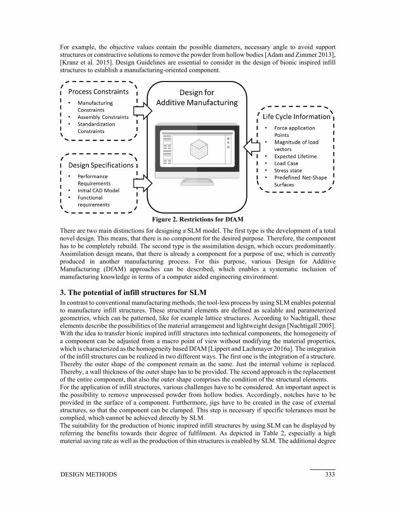
For example, the objective values contain the possible diameters, necessary angle to avoid support structures or constructive solutions to remove the powder from hollow bodies [Adam and Zimmer 2013], [Kranz et al. 2015]. Design Guidelines are essential to consider in the design of bionic inspired infill structures to establish a manufacturing-oriented component.
Figure 2. Restrictions for DfAM
There are two main distinctions for designing a SLM model. The first type is the development of a total novel design. This means, that there is no component for the desired purpose. Therefore, the component has to be completely rebuild. The second type is the assimilation design, which occurs predominantly. Assimilation design means, that there is already a component for a purpose of use, which is currently produced in another manufacturing process. For this purpose, various Design for Additive Manufacturing (DfAM) approaches can be described, which enables a systematic inclusion of manufacturing knowledge in terms of a computer aided engineering environment.
3. The potential of infill structures for SLM In contrast to conventional manufacturing methods, the tool-less process by using SLM enables potential to manufacture infill structures. These structural elements are defined as scalable and parameterized geometries, which can be patterned, like for example lattice structures. According to Nachtigall, these elements describe the possibilities of the material arrangement and lightweight design [Nachtigall 2005]. With the idea to transfer bionic inspired infill structures into technical components, the homogeneity of a component can be adjusted from a macro point of view without modifying the material properties, which is characterized as the homogeneity based DfAM [Lippert and Lachmayer 2016a]. The integration of the infill structures can be realized in two different ways. The first one is the integration of a structure. Thereby the outer shape of the component remain as the same. Just the internal volume is replaced. Thereby, a wall thickness of the outer shape has to be provided. The second approach is the replacement of the entire component, that also the outer shape comprises the condition of the structural elements. For the application of infill structures, various challenges have to be considered. An important aspect is the possibility to remove unprocessed powder from hollow bodies. Accordingly, notches have to be provided in the surface of a component. Furthermore, jigs have to be created in the case of external structures, so that the component can be clamped. This step is necessary if specific tolerances must be complied, which cannot be achieved directly by SLM. The suitability for the production of bionic inspired infill structures by using SLM can be displayed by referring the benefits towards their degree of fulfilment. As depicted in Table 2, especially a high material saving rate as well as the production of thin structures is enabled by SLM. The additional degree
DESIGN METHODS 333

of fulfilment is shown with the notation for a low degree of fulfillment ≙ as well as for a high degree of fulfilment ≙ [Lippert and Lachmayer 2016a].
Table 2. Potential of bionic inspired infill structures
Material saving Integrated flow channels Function integration (Mass) Customization Thin structures Design aspects Force flow adapted Net-Shape geometries
3.1 Bionic Design Elements
In compliance with this knowledge, different bionic inspired infill structures are analysed as separated parts, which are defined as Bionic Design Elements (BDEs). According to the investigation, an extension of the solution space towards complex geometries is sought after the validation of the BDEs. For this investigation, a design catalog is build up, which enables a structured examination of the analysed elements by using objective values. The objective is to identify the predominated load cases in a component and to select the optimal structure by using the design catalog. Suitable BDEs for SLM are elements, which can be manufactured by other production methods only with great expense. For example truss-, bamboo-, honeycomb- or bone structures can be identified [Nachtigall 2005]. The identified BDEs has to be structured in a next step. According to Figure 3, three structural stages are described:
1. The first outline level describes the basic form, in which the BDEs can be integrated. The differentiation is made in cylindrical and cuboid forms.
2. The second outline level describes the origin of the BDEs. Here, a differentiation in structurally and organic is made for both basic forms.
3. The third outline level describes the occurrence of the BDEs. In this case, the classification is performed of the collated in the literature elements which have a great potential for the SLM.
Figure 3. Structure of Bionic Design Elements
Based on the identified BDEs, standardized demonstrators are modelled as 3D geometries. With the objective to simulate defined load cases (tensile, compression, bending and torsion), the BDEs are transferred towards cylindrical and cuboid models. Figure 4 depicts examples of the demonstrators as a cylindrical and a cuboid model, with the alignment in the coordinate system.
334 DESIGN METHODS

Figure 4. Alignment of the demonstrators in the coordinate system
For an application specific use of the identified BDEs, an examination of the load-specific characteristics is necessary. Based on Finite Element Methods (FEM), this examination is carried out. The standardized 3D geometry models are loaded with identical forces. Using the material properties of the standard powder ALSi10Mg, the models are prepared [EOS 2011]. According to Figure 4, two different load situations are applied. The first situation (1) has a clamp in the x/y layer. The tensile and compression load is applied in the z direction. The Bending load is applied in the x and y direction. In the second situation (2), the demonstrator is clamped in the x/z layer. Tensile and compression is applied in the y direction as well as the bending load in the y and z direction. As depicted in Table 3, the load cases are applied.
Table 3. Properties for FEM simulation
Cylindrical Cuboid
Dimension [mm] h = 30; b = 30; t = 30 Ø = 30 ; h = 30
Compression [N] 200 N 200 N
Tension [N] 200 N 200 N
Bending [N] 200 N 200 N
Torsion [Nm] 200 Nm 200 Nm
3.2 Design catalog
The achieved results are listed in form of a design catalog. Within this catalog, a classification in a structure, an access and a main part is done. Thereby, the main part describes the identified BDEs and gives a visualization of the elements. To classify the listed elements, the structure part defines criteria, which relate to the structure of BDEs, as depicted in Figure 3. At last, the access part contains the simulation results. Depending on the direction of the loads, 1st principle stresses, 3rd principle stresses, the equivalent stresses (von Mises) as well as the maximum deformation and strain are given. Furthermore, the optimal orientation of a structure is given in the design catalog. An excerpt of this catalog is shown in Figure 5, which depicts selected structures with their optimal loading direction and their simulation results. As shown in Figure 5, the suitability of a BDE depends on the type of load case. For example honeycombs are a suitable possibility, if a component is mostly loaded with compression. By contrast, timber structures are suitable for a bending stress and lattice structures are preferable in case of tensile. Based on a load case, the design catalog enables to give a further statement about the optimal infill structure. In addition to the simulation results, also the weight of the demonstrators as well as the weight advantage compared to a solid volume is given. Each structure is analysed with varying parameters for the wall thickness and the mesh size. Thereby, the modelling is carried out by taking the design guidelines into account, which reflect the possibilities of the machine and the process to enable a manufacturing-oriented component design. Thus, a total amount of 15 different BDEs - each with 3 different parameter sets - are examined.
DESIGN METHODS 335

Figure 5. Design catalog of the BDEs
4. Approach to Adapt a demonstrator To demonstrate the design catalog, a wheel carrier of a double wishbone suspension is applied as a demonstrator. Thereby, not the entire topology of the component should be replaced by using BDEs. Rather, a selection of appropriate areas has to take place. In addition to the consideration of restrictions and guidelines, a design objective has to be set for the actual design process. This object specifies the purpose for which the component has to be designed. From the criteria of the stiffness, strength, weight, costs or functional integration, a multi-criteria objective can be formulated [Lippert and Lachmayer 2016b]. With the objective to build up a lightweight component, areas with low stresses are taken into account.
Figure 6. Boundary conditions of the demonstrator
336 DESIGN METHODS
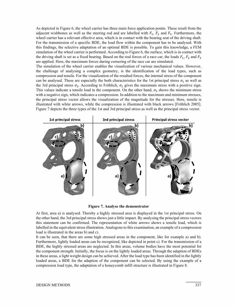
As depicted in Figure 6, the wheel carrier has three main force application points. These result from the adjacent wishbones as well as the steering rod and are labelled with , and . Furthermore, the wheel carrier has a relevant effective area, which is in contact with the bearing seat of the driving shaft. For the transmission of a specific BDE, the load flow within the component has to be analysed. With this findings, the selective adaptation of an optimal BDE is possible. To gain this knowledge, a FEM simulation of the wheel carrier is performed. According to Figure 6, the surface, which is in contact with the driving shaft is set as a fixed bearing. Based on the real forces of a race car, the loads , and are applied. Here, the maximum forces during cornering of the race car are simulated. The simulation of the wheel carrier enables the visualization of various mechanical values. However, the challenge of analysing a complex geometry, is the identification of the load types, such as compression and tensile. For the visualization of the resulted forces, the internal stress of the component can be analysed. These are especially the both characteristics for the 1st principal stress as well as the 3rd principal stress . According to Fröhlich, gives the maximum stress with a positive sign. This values indicate a tensile load in the component. On the other hand, shows the minimum stress with a negative sign, which indicates a compression. In addition to the maximum and minimum stresses, the principal stress vector allows the visualization of the magnitude for the stresses. Here, tensile is illustrated with white arrows, while the compression is illustrated with black arrows [Fröhlich 2005]. Figure 7 depicts the three types of the 1st and 3rd principal stress as well as the principal stress vector.
Figure 7. Analyse the demonstrator
At first, area a) is analysed. Thereby a highly stressed area is displayed in the 1st principal stress. On the other hand, the 3rd principal stress shows just a little impact. By analysing the principal stress vectors this statement can be confirmed. The representation of white arrows shows a tensile load, which is labelled in the equivalent stress illustration. Analogous to this examination, an example of a compression load is illustrated in the areas b) and c). It can be seen, that there are some high stressed areas in the component, like for example a) and b). Furthermore, lightly loaded areas can be recognized, like depicted in point c). For the transmission of a BDE, the highly stressed areas are neglected. In this areas, volume bodies have the most potential for the component strength. Initially, the focus is on the lightly loaded areas. Through the adaption of BDEs in these areas, a light weight design can be achieved. After the load type has been identified in the lightly loaded areas, a BDE for the adaption of the component can be selected. By using the example of a compression load type, the adaptation of a honeycomb infill structure is illustrated in Figure 8.
DESIGN METHODS 337

By referring to the design objective - to achieved a weight reduction through the application of thin structures (see Table 2) - the adaption of bionic inspired infill structures leads to a weight reduction of about 10 % for the shown demonstrator. However, there is still considerable potential for optimization, because the geometry can be better adapted to the design potentials of SLM. Furthermore, a major challenge is the powder removal. For example, for the adaption of a honeycomb structure adequate notches have to be provided. However, a notch at one end of the structure is not enough, because the raster elements are separated from each other. Thus, a connection between the honeycombs has to be provided, which affects the mechanical properties of the component. For the industrial application the effect on the dynamic behaviour has to be clarified, because (bionic inspired) infill structures cause a notch effect for the component. Furthermore, economies of scale in the surface properties for thin-walled structures have to be analysed. For industrial application, a focus for components with non-structural properties is sensible. Thus, the substitution of components, which have no safety significance and are just lightly loaded, have to be examined initially.
Figure 8. Example application of the demonstrator
5. Conclusion Additive Manufacturing offers new design possibilities, which enables an added value compared to other manufacturing processes. Therefore, a component can be designed by various DfAM approaches. One approach, which exploits a great design freedom referring to SLM is the homogeneity based DfAM approach. Thereby, the objective is the application of bionic inspired infill structures - such as lattice structures or honeycombs - to adjust the homogeneity of a component from a macro point of view. The compilation of various elements provides the diversity of possible structural, which have a bionic origin and are suitable for the production in SLM. The investigations have shown, that these structures comprise different advantages depending on the type of load. Thus, the orientation-dependent loads of the elements are examined. Furthermore, the optimal orientations for the integration of the structures in
338 DESIGN METHODS

a component have been identified. As a result, a design catalog is build up, which lists the mechanical properties of the examined elements. In addition, an approach to consider the catalog for designing a component is shown. Therefore, a demonstrator is analysed regarding the force flow. Using FEM, the forces are simulated, which occurs during the real application of the component. In a next step, the simulation results are examined. As a major challenge, the representation of isolated load conditions is identified. In the developed approach, a simplified assumption of load conditions is applied. Therefore, the principal stresses of the component are analysed. For an industrial application of bionic design elements, further investigations are necessary. In this course, various constrains have to be clarified. For example, the fatigue strength of bionic structures produced in SLM are currently unknown. In addition to dynamic loads, also further investigations towards the static behaviour have to be performed. Thus, the application of the design catalog to construct simple geometries is planned in the next steps.
References Adam, G. A. O., Zimmer, D., "Design for Additive Manufacturing - Element transitions and aggregated structures", CIRP Journal of Manufacturing Science and Technology, Paderborn, Germany, 2013. Birkhofer, H. (ed.), Franke, H.-J., "The future of Design methodology - What Designers can learn from Leonardo, an Ingenious Artist, Scientist and Engineer", Springer Verlag, London, England, 2011. Buchmayr, B., Panzl, G., "Eine SWOT-Analyse zum Einsatz Additiver Fertigung für metallische Bauteile", Springer Verlag, Wien, Austria, 2014. EOS GmbH, "Material data sheet - EOS AlSi10Mg", München, 2011. Fröhlich, P., "FEM-Anwendungspraxis - Einstieg in die Finite Elemente Analyse Zweisprachige Ausgabe Deutsch/ Englisch", Springer Verlag, Wiesbaden, Germany, 2005. Jessel, B., Tschimpke, O., Walser, M., "Produktivkraft Natur", Hoffmann und Campe Verlag, Hamburg, Germany, 2009. Kranz, J., Herzog, D., Emmelmann, C., "Design guidelines for laser additive manufacturing of lightweight structures in TiAl6V4", Journal of Laser Applications, 2015. Lachmayer, R., Gembarski, P., Gottwald, P., Lippert, R. B., "The Potential of Product Customization using Technologies of Additive Manufacturing, Managing Complexity", Proceedings of the 8th World Conference on Mass Customization, Personalization and Co-Creation (MCPC 2015), Montreal, Canada, 2015a. Lachmayer, R., Gottwald, P., Lippert, R. B., "Approach for a comparatively evaluation of the sustainability for additive manufactured aluminum components", Proceedings of the 20th International Conference on Engineering Design (ICED15), Milan, Italy, 2015b. Lachmayer, R., Wolf, A., Kloppenburg, G., "Rapid Prototyping of reflectors for vehicles lighting using laser activated remote phosphor", SPIE Photonics West, San Francisco, US, 2015c. Lachmayer, R., Lippert, R. B., Fahlbusch, T., "3D-Druck beleuchtet - Additive Manufacturing auf dem Weg in die Anwendung", Springer-Vieweg, Berlin, Germany, 2016. Lippert, R. B., Lachmayer, R., "Restriction oriented Component Design for Selective Laser Melting", Proceedings of the Rapid.Tech – International Trade Show & Conference for Additive Manufacturing, Trade Forum Science, Erfurt, Germany, 2016a. Lippert, R. B., Lachmayer, R., "Topology Examination for Additive Manufactured Aluminum Components", Proceedings of the Direct Digital Manufacturing Conference (DDMC 2016), Berlin, Germany, 2016b. Nachtigall, W., "Vorbild Natur - Bionik-Design für funktionelles Gestalten", Springer Verlag, Berling and Heidelberg, Germany, 1997. Nachtigall, W., "Bionik - Grundlagen und Beispiele für Ingenieure und Naturwissenschaftler", Springer Verlag, Saarbrücken, Germany, 2002. Nachtigall, W., "Biologisches Design - Systematischer Katalog für bionisches gestalten", Springer Verlag, Berlin, Germany, 2005. VDI Gesellschaft Produktion und Logistik, "VDI 3405: Additive manufacturing processes, rapid manufacturing - Basics, definitions, processes", VDI Handbuch, Berlin, Germany, 2014. VDI Gesellschaft Produktion und Logistik, "VDI 3405 Blatt 3: Additive manufacturing processes, rapid manufacturing - Design rules for part production using laser sintering and laser beam melting ", VDI Handbuch, Berlin, Germany, 2015.
DESIGN METHODS 339

Zerbst, W. E., "Bionik - Biologische Funktionsprinzipien und ihre technischen Anwendungen", Springer Verlag, Wiesbaden, Germany, 1987.
Rene Bastian Lippert, M. Eng. Leibniz Universität Hannover, Institute of Product Development Welfengarten 1a, 30167 Hannover, Germany Email: [email protected]
340 DESIGN METHODS