biomechanical evaluation of two surgical methods of … · to pam arnold and pete jobst for their...
TRANSCRIPT

Biomechanical Evaluation of Two Surgical Methods of Stabilization of the Atlantoaxial Joint
Kelli M. Kopf
Thesis submitted to the Faculty of Virginia Polytechnic Institute and State University as partial fulfillment of the requirements for the degree of
Master of Science
in Biomedical and Veterinary Science
Karen Dyer Inzana, chair Otto I. Lanz
John H. Rossmeisl Jr. Steven Elder
June 27th, 2013 Blacksburg, VA
Keywords: Atlantoaxial, Kishigami tension band, Pins and polymethylmethacrylate, canine, subluxation
Copyright © 2013, Kelli M. Kopf

ii
Biomechanical Evaluation of Two Surgical Methods of Stabilization of the Atlantoaxial Joint
Kelli M. Kopf
(Abstract)
Several methods of surgical stabilization of the atlantoaxial joint are described in the veterinary literature. Threaded acrylic pins placed ventrally together with polymethylmethacrylate (PMMA) is a well-established technique that has been widely used in clinical cases. However, Kishigami tension bands are a less technically demanding procedure with potentially fewer complications. The purpose of this study was to biomechanically compare these two techniques in ventral-to-dorsal bending in both mature and immature dogs.
Seventeen normal canine cadavers <15kg were collected and radiographed to determine skeletal maturity. The cervical spines were dissected leaving bony and ligamentous structures intact. Eight mature spines and 9 immature spines were randomly divided into two groups. In one group a Kishigami tension band was applied over the dorsal arch of the atlas and attached to the spinous process of the axis using orthopedic wire. In the second group, six acrylic pins were placed ventrally in the atlas, axis, and transarticularly. The pins were then cut and covered with PMMA. The specimens were potted in custom steel pots and biomechanically analyzed in ventral-to-dorsal four-point bending. Load-displacement curves representing the degree of stiffness were compared between the groups. Stabilization using ventral pins and PMMA had a significantly greater stiffness than a Kishigami tension band when bending in ventral to dorsal bending. Within the stabilized vertebral segment, there was no significant difference between the stiffness of immature vs. mature bone. Further analysis in torsion and analysis in abnormal dogs will be helpful in establishing the clinical significance of these findings.
This work was funded by a grant from the Virginia Veterinary Medical Association’s Veterinary Memorial Fun

iii
Acknowledgements
To the Virginia Veterinary Medical Association for their generosity in funding this project.
To my committee members, Dr. Karen Inzana, Dr. Otto Lanz, and Dr. John Rossmeisl for their dedication to this project, patience, and continued support.
To Mississippi State University Biomedical Engineering facility for the use of laboratory space during biomechanical testing.
To Dr. Steven Werre for his assistance with statistical analysis.
To Pam Arnold and Pete Jobst for their assistance with collecting canine cadavers.
To Dr. Theresa Pancotto for her support and guidance throughout my residency.
To Dr. Samantha Emch for her friendship, entertainment, and cooperation during the past year.
To Dr. KW for her commitment and patience.

iv
Table of Contents Page(s)
Abstract ii
Acknowledgements iii
Table of Contents iv
Multimedia Object Listing vi
Alphabetical Key of Abbreviations viii
Chapter 1: Introduction and Literature Review
Introduction 1
Literature Review 3
Anatomy and Embryology of the Atlantoaxial Joint 3
Atlantoaxial Subluxation 6
Nonsurgical Management 8
Surgical Management 9
Surgical Management – Dorsal Approach 10
Surgical Management – Ventral Approach 15
Spine Biomechanics 22
Cadaver Preparation 24
Chapter 2: Materials and Methods
Part 1: Specimen Collection and Preparation 26
Part 2: Surgical Technique 27
Part 3: Biomechanical Analysis 29
Part 4: Data Analysis 31
Chapter 3: Results 32
Chapter 4: Discussion 34

v
Page(s)
Chapter 5: Future Directions 39
References 41
Figures 45
Tables 54
Vita 56

vi
Multimedia Objects
List of Figures Page
Figure 1.1: Anatomy of the Atlantoaxial Joint 4
Figure 1.2: Survey Radiographs of Atlantoaxial Subluxation (A) and Odontoid Aplasia (B)
7
Figure 1.3: T2-weighted Sagittal MRI of a Dog with Atlantoaxial Subluxation. 7
Figure 1.4: External Coaptation for Conservative Management of Atlantoaxial Subluxation.
9
Figure 1.5: Design of Original Kishigami Tension Band Figure 1.6: Four Point Bending Figure 1.7: Load/Displacement Curve Figure 2.1: Immature Specimen Figure 2.2: Application of the Kishigami Tension Band Figure 2.3: Application of Pins and PMMA Ventrally at the Atlantoaxial Joint Figure 2.4: Potting Procedure for Biomechanical Testing Figure 2.5: Biomechanical Analysis Figure 3.1: Generated Load/Displacement Curve of Ventral Implants and Kishigami Tension Band Figure 3.2: Initial Slope of Load/Displacement Curve for Group K vs. Group V
12 24 24 26 28 29 29 30 32 32
Figure 3.3: Box Plot of Stiffness for Group K and Group V
Figure 3.4: Initial Slope of Load/Displacement Curve for Group I vs. Group M
32
33
Figure 3.5: Box Plot of Stiffness for Group I and Group M 33

vii
List of Tables Page
Table 2.1: Number of Specimens per Group 27
Table 3.1: Descriptive Statistics for Groups 32
Table 3.2: Differences of Group Least Mean Squares 32
Table 3.3: Type III Tests of Fixed Effects 33
Table 3.4: Simple Effect Comparisons Implant*MI Group Least Squares Means by MIGroup; Adjustment for Multiple Comparisons: Holm-Tukey
33
Table 3.5: Simple Effect Comparisons Implant*MI Group Least Squares Means by Implant; Adjustment for Multiple Comparisons: Holm-Tukey
33
viii
Abbreviations/symbols
AA Atlantoaxial
CT Computed Tomography
MRI Magnetic Resonance Imaging
N Newtons
PMMA Polymethylmethacrylate

1
Chapter 1: Introduction and Literature Review
Introduction
The atlantoaxial joint is a unique joint in the spine due to the absence of an intervertebral
disc and the presence of an odontoid process along with ligamentous attachments between the
occipital bone, atlas, and axis. These ligaments provide most of the stability for the atlantoaxial
joint. The atlantoaxial joint is capable of many movements including rotation, flexion,
extension, and lateral bending.35 The unique aspects of this joint make it more susceptible to
subluxation associated with congenital abnormalities or acquired trauma. Atlantoaxial
subluxation typically occurs in small breed dogs, although it has been seen in all sizes of dog and
even in other species.1-4, 25 This condition can be associated with severe neurologic deficits, and
even death due to compression on the cranial cervical spinal cord and resulting respiratory
depression. Stabilization of the atlas and axis can be accomplished by external support
(conservative management) or by surgical stabilization. There are several methods of surgical
management described, including both dorsal and ventral approaches to the atlantoaxial joint.
The Kishigami tension band, applied dorsally, was initially described in 1984 and has more
recently been evaluated in a clinical setting. 16, 18 A ventral approach using pins and
polymethylmethacrylate is a common stabilization method used in the atlantoaxial joint. 20, 29, 30,
31 To the author’s knowledge, there is no biomechanical study available comparing the stability
provided by the Kishigami tension band when compared to other modalities. The primary
objective of this study is to evaluate the biomechanical properties of the Kishigami tension band
when compared to ventral pins and PMMA in mature and immature dogs. We hypothesize that
the ventral pins and PMMA construct will have a significantly greater stiffness than the

2
Kishigami tension band in ventral to dorsal bending. We anticipate that our results will help
guide surgeons’ implant choices as well as encourage additional biomechanical studies on other
available methods of atlantoaxial stabilization.

3
Literature Review
Anatomy and Embryology of the Atlantoaxial Joint
The first cervical vertebra, or the atlas, articulates with the skull cranially, and the second
cervical vertebra, the axis, caudally. These two vertebrae have unique shapes when compared to
other vertebrae in the vertebral column. The cranial articulation between the occipital bone and
atlas is formed between the occipital condyles and deep concavities on the cranial surface of the
atlas (cranial articular fovea). These cranial articular fovea cup the occipital condyles and form a
joint whose main movement is flexion and extension, allowing for a free up and down, or “yes”,
movement of the calvaria in relation to the rest of the spine.9 This joint has a range of
approximately 90° when fully flexed.9 The caudal articular surface between the atlas and the
axis consists of two shallow glenoid cavities that form an articulation with the cranial articular
surface of the axis, which together with a loose joint capsule allows for more rotary movement of
the head. For this reason, this joint is often called the “no” joint. The atlantoaxial joint is a
diarthrodial articulation.29 It differs from other joints in the vertebral column due to the lack of
an intervertebral disc and the incorporation of a bony prominence (odontoid process) along with
ligamentous attachments.
The first cervical vertebra has a flat dorsal arch and differs from other vertebra because a
spinous process is not formed. The transverse processes of the atlas are wing-like projections
laterally. The body of the atlas is smaller, flatter, and thinner than the bodies of other cervical
vertebrae.5 The atlas contains bilateral alar foramina or notches on the cranial and lateral surface
of the dorsal arch. The spinal cord passes through the central vertebral foramen, which is present
in all vertebrae.5 The transverse foramen is a short oblique canal through the transverse process
of the atlas. The vertebral vein and artery run through this space.5 The lateral vertebral foramen

4
sits at the craniodorsal part of the vertebral arch, and contains the vertebral artery.5
Embryologically, the adult atlas develops from three centers of ossification. One center forms
the ventral arch, and two additional sections form the lateral masses and fuse at midline to
become the dorsal arch.9 These centers fuse around 4 months of age. 6
The second cervical vertebra, or the axis, has an elongated dorsal spinous process that is
blade-like cranially and expanded caudally. The ventral aspect of this vertebra contains two deep
fossae separated by a median crest. The odontoid process is a cranioventral process of the ventral
aspect of C2 that lies within the vertebral foramen of the atlas. The transverse foramen of the
axis is present near the base of the transverse process (Figure 1.1).5 Embryologically, the axis is
formed from seven bony elements.6 Centrum 2 forms the main bulk of the vertebral body. There
are two lateral centers that form the arch and its processes, which fuse to centrum 2 at around 3
months of age.6 One section (centrum 1) forms the cranial articular surface of the axis body and
the odontoid process. This fuses later at 7-9 months of age.6 There is a smaller ossification center
at the very apex of the odontoid process called the centrum of the proatlas which is not present in
all dogs. The proatlas fuses with centrum 1 at 3 to 4 months of age.6 A small section just caudal
and ventral to centrum 1 is intercentrum 2, which fuses with centrum 2 at 4 months.6 Finally, a
narrow caudal epiphyseal ossification completes the body of the axis around 7-9 months.6
The ligamentous attachments of the occipital bone, atlas, and axis differ from any other
vertebral articulations in the vertebral column. The major ligamentous attachments of the atlanto-
occipital joint include the lateral atlanto-occipital ligament, which courses cranioventrolaterally
from the lateral part of the dorsal arch of the atlas to the jugular process of the occipital bone,
and a small ligament from the inner surface of the ventral arch of the atlas to the lateral part of
the foramen magnum .5 In addition, the dorsal atlanto-occipital membrane is a broad strap-like

5
membrane that is divided on midline and runs at an oblique angle from the dorsal edge of the
foramen magnum caudally to the dorsal arch of the atlas, bilaterally.5 The ventral atlanto-
occipital membrane associates with the synovial joint and forms a thin joint capsule between the
ventral aspect of the foramen magnum and the ventral arch of the atlas.5
The ligaments of the atlantoaxial joint include the transverse ligament, alar ligaments,
and the apical ligament (Figure 1.1).5 The transverse ligament is a strong ligament that attaches
one side of the ventral arch of the atlas to the other. The transverse ligament lies over the
odontoid process within the vertebral foramen. This ligament limits ventrodorsal movement at
the atlantoaxial joint.5 The apical ligament is thin and travels from the odontoid process to the
ventral aspect of the foramen magnum.5 The paired alar ligaments travel from the odontoid
process to the medial aspect of each occipital condyle, bilaterally.5 The joint capsule is thin and
extends into a fibrous layer that runs left to right between the dorsal arch of the atlas and the arch
of the axis. This fibrous layer is called the dorsal atlantoaxial membrane.5 The nuchal ligament
attaches to the caudal aspect of the spinous process of the axis and runs caudally to the spinous
process of T1.5
The stability of the vertebral column in general is established by the bone, intervertebral
disc, ligaments, membranes, and muscular attachments. External forces that act on the spine
include bending (dorsoventral and lateral), rotation, shear, and axial loading.4 The vertebral
body acts as a buttress to resist bending and axial loading, and the articular facets resist all
external forces.4 The intervertebral disc is considered to be the single most important stabilizing
factor against rotation and lateral bending .15 The assessments of these specific portions of the
spine are based on the thoracolumbar spine. The atlantoaxial joint is unique in that the basic
shape of C1 and C2 are different than other vertebrae, and the joint does not contain an
6
intervertebral disc. The odontoid process and its associated ligaments are believed to provide
most of the stability. To the author’s knowledge, there have been no published veterinary reports
specifically evaluating the biomechanics of the atlantoaxial joint. As previously mentioned, the
major motion in the atlantoaxial joint is rotational. The major motion in the atlantooccipital joint
is ventral and dorsal flexion. Bending in the ventral direction in dogs with atlantoaxial instability
is the most likely movement to cause compression of the spinal cord, especially if the odontoid
process is intact or dorsally deviated. Bending in the ventral direction is the force that implants
are designed to neutralize in order to prevent subluxation and spinal cord trauma from the
odontoid process. For this reason, ventral bending will be the primary force evaluated in this
study.
Atlantoaxial Subluxation
Atlantoaxial subluxation is a condition that most commonly occurs in young, small breed
dogs, although it can occur in large breed dogs and cats. 1-4, 25 There is no apparent sex
predilection, however 56% of the dogs with atlantoaxial subluxation in the reported literature are
less than one year of age.3 Atlantoaxial subluxation can arise secondary to odontoid aplasia or
hypoplasia, fracture or separation of the odontoid process, or failure of the ligaments due to
rupture or malformation.25 Ligamentous damage is generally associated with trauma, although a
congenital absence of ligaments has been reported.11 In one report of 46 dogs with atlantoaxial
subluxation, odontoid process aplasia was noted in 46% of dogs, abnormal odontoid process
conformation in 30%, and a normal odontoid process was noted in 24% of dogs with atlantoaxial
subluxation.25

7
Clinical signs associated with atlantoaxial subluxation are consistent with compression of
the cranial cervical spinal cord. A review of the literature revealed gait deficits in 84% of
patients with atlantoaxial subluxation, and cervical hyperesthesia is noted in 61% .3 Gait deficits
vary from mild ataxia to tetraplegia and are dependent on the severity of spinal cord compression
and damage. Severe spinal cord compression can result in hypoventilation and sudden death.3
Diagnosis can be accomplished using survey radiography, CT, or MRI scan of the cervical
spine.3 Lateral cervical radiographs will demonstrate an increased distance between the dorsal
arch of C1 and the most cranial aspect of the spinous process of C2, as well as dorsal
displacement of the axis.3 Gentle ventroflexion in the lateral view radiographically or
fluoroscopically may be helpful to assess mild instability, however extreme caution is necessary
because spinal cord compression is more likely in this view.3 The odontoid process should also
be assessed on survey films in the ventrodorsal view or an open-mouth rostrocaudal view,
although the presence of an abnormal odontoid process alone is not sufficient evidence for
atlantoaxial instability (Figure 1.2). 3, 10, 12, 13 Computed tomography (CT) may also be
implemented to visualize the presence of the odontoid process and assess ossification of the
bone. Past research has shown that dogs with incomplete ossification of the atlas are 35 times
more likely to develop atlantoaxial subluxation than dogs with complete ossification of the atlas.7
Magnetic Resonance Imaging (MRI) can also be used to assess bony malformation in addition to
ligamentous structures.39 MRI can also elucidate spinal cord compression and secondary
changes such as intramedullary hyperintensity on T2-weighted images, syringohydromyelia, or
other concurrent congenital abnormalities (Figure 1.3).4 The presence of suspected extensive
spinal cord malacia or syringohydromyelia on MRI may provide prognostic information for
patients with atlantoaxial subluxation.14

8
Nonsurgical Management
Nonsurgical management of atlantoaxial subluxation includes immobilization with a
cervical splint, exercise restriction, the use of analgesics, and sometimes the administration of
anti-inflammatory medications.4, 35 The goals of treatment include decompression of the spinal
cord by reduction of the subluxation and stabilization of the atlantoaxial joint.35 Stability with
this method depends on the formation of fibrous scar tissue around the atlantoaxial joint.3
Historically, nonsurgical treatment has been reserved for dogs with clinical signs of cervical pain
only, dogs with mild neurologic deficits and minimal anatomic displacement, dogs with
radiographically normal odontoid processes, and due to client or patient constraints. 3, 35
There have been four reports totaling 31 cases of atlantoaxial subluxation managed
nonsurgically in the literature. 25, 34-36 A majority of the dogs were young at the time of
presentation, with a median age of 2 in one study35, and 20/24 dogs under a year of age in
another report.34 One report found that dogs older than 2 years of age at admission had a
significantly worse final outcome 25, while another study found no significant association
between age and outcome of cases.35 Twenty of the 30 cases reported had minor or major
trauma associated with the onset of clinical signs.34, 35 One study reported no difference in
outcome between dogs that did and did not have a normal odontoid process.35 The duration of
clinical signs ranged from 1 day to 3 years.35 Havig et al. reported that the rate of onset affected
final outcome. Dogs with greater than 30 days of clinical signs prior to presentation were more
likely to have a poorer outcome than dogs with less than 30 days duration of clinical signs.35
Nonsurgical treatment in all reports involved the application of a splint around the cervical spine
and cage rest.25, 34-36 Corticosteroids were also administered prior to presentation in 12/19 cases
in one report.35 The material used and length of the splint were variable. Havig et. al. used

9
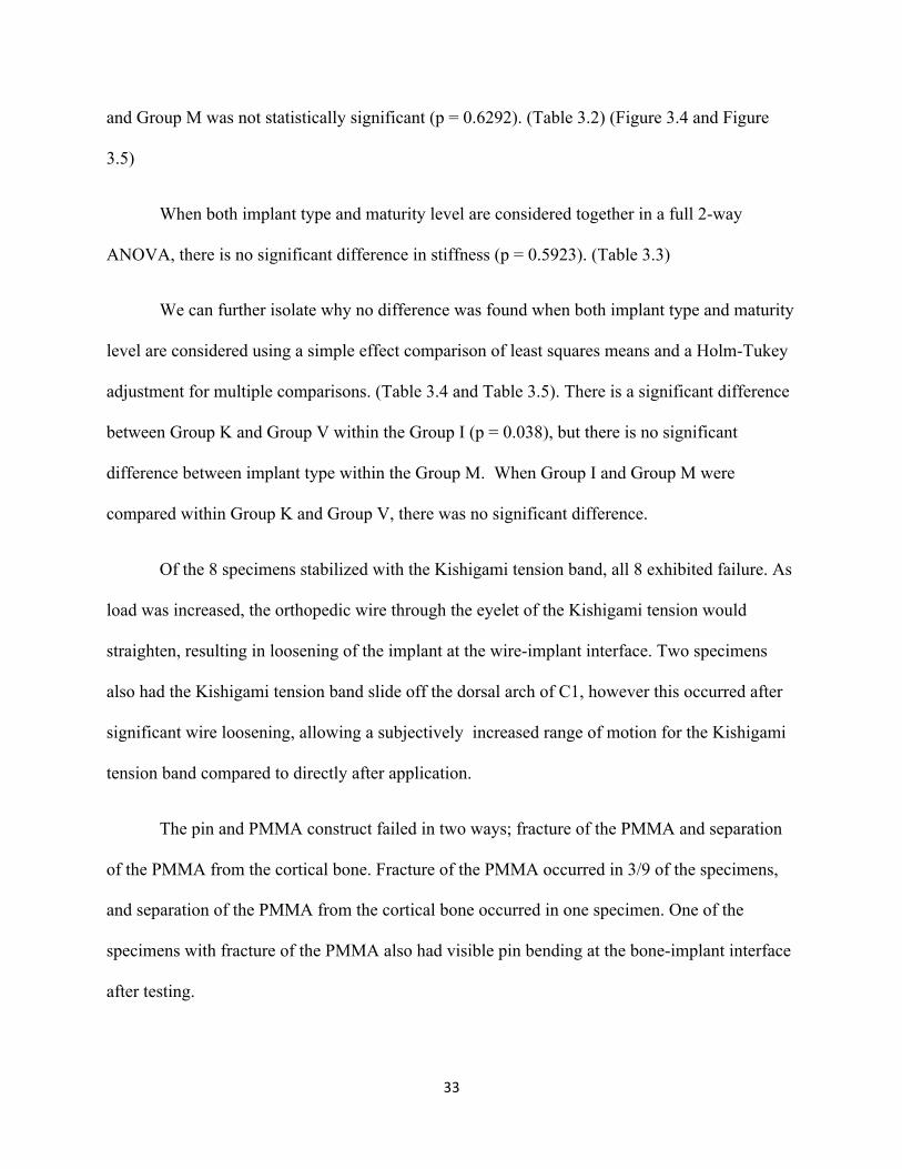
fiberglass cast material and soft padding extending from the rostral extent of the mandible
caudally to the xiphoid process in most dogs (Figure 1.4). In 4 dogs the bandage was extended
caudally to the last thoracic vertebra. Lorinson et. al. constructed a neck wrap consisting of a
well-padded bandage placed from the caudal edge of the mandible to the shoulders or, in very
small dogs, a padded Styrofoam cup. Post-application radiographs in one report revealed
improved alignment in 5 of the 10 cases radiographed.35 Duration of immobilization varied from
4 weeks to 15 weeks. At the time of splint removal, the outcome was considered good in 26/31
reported cases (83%).35, 34, 36 The definition of a good outcome involved voluntary ambulation in
all dogs, and included a normal neurologic exam in 16 dogs. Long-term outcome after one year
involved euthanasia related to atlantoaxial subluxation in 8/31 dogs.34, 35 A concern with
nonsurgical management of atlantoaxial subluxation is the recurrence of clinical signs following
removal of the neck brace.4 Havig et. al. suggested that surgical stabilization may have provided
improved stability in the 6 cases that were euthanized or died in that study, and surgical
stabilization should be recommended in cases of relapse.35 Complications associated with splint
application include corneal ulcers, moist dermatitis, decubital ulcers, otitis externa, and
respiratory distress.35 Havig et. al. suggests that nonsurgical management should be considered
in cases with an acute onset of neurologic signs, immature bone incapable of firmly holding
implants, and where there are financial constraints. Surgical stabilization should be
recommended in cases with a chronic history of clinical signs, patients with mature bone, and
when a relapse of clinical signs or failure of nonsurgical management occurs.35
Surgical Management
The goals of surgical management are similar to nonsurgical management:
decompression of the spinal cord by reduction and stabilization of the atlantoaxial joint. Surgery

10
in the craniocervical region is complicated by the unique anatomy of the cranial cervical
vertebrae and by the substantial spinal movement allowed in this region.37 There are few points
for instrument fixation and bony fusion attachment.
Surgical Management - Dorsal Surgical Approaches
Surgical stabilization of the atlantoaxial joint using a dorsal approach has been described
using multiple methods including dorsal wiring, dorsal suture, nuchal ligament fixation,
Kishigami tension band, and dorsal cross-pinning.9, 16-18, 23, 22, 26 The dorsal wiring procedure was
described in the initial paper defining atlantoaxial subluxation in 1967,9 and later modified.23 The
procedure involves a dorsal approach to the atlantoaxial space. Two holes are then drilled in the
spinous process of the axis, and the dorsal atlanto-occipital membrane is incised over the dorsal
arch of the atlas. A loop of orthopedic wire is passed ventral to the dorsal arch of the atlas in a
caudal-to-cranial direction through the vertebral canal and retrieved from the atlanto-occipital
space. The free end of wire is passed through the previously-drilled caudal hole in the axis and
the two ends are twisted together. The cranial loop of the wire is folded caudally and cut. An
end is passed through the cranial hole in the spinous process of the axis, and the two free ends
are twisted together.10 Alternate techniques include using a single strand of wire beneath the
dorsal arch of the atlas, or passing wire through predrilled holes in the arch of the atlas.9, 19, 23
Modifications of this procedure include the use of nonmetallic suture or the nuchal ligament to
pass under the dorsal arch of the atlas.22, 21 When using suture in place of orthopedic wire, the
approach and procedure are similar to the dorsal wiring procedure. 21 Orthopedic wire is used to
pass under the dorsal arch of the atlas and non-metallic suture is threaded through this loop,
which is then drawn back under the arch of the atlas. The strand is cut, and the suture is threaded
through two holes created in the spinous process of the axis, the same as in the dorsal wiring

11
procedure.21 When using the nuchal ligament, the approach is the same as for dorsal wiring.22
The cranial attachment of the nuchal ligament is maintained, and the ligament is split
longitudinally and transected at its caudal attachment to T1. Both free ends are then passed
ventral to the dorsal arch of the atlas using a looped wire in the same fashion as the dorsal wiring
procedure. The ends of the ligament are then tied to each other over a notch that is created in the
dorsal aspect of the spinous process of the axis.22
The dorsal wiring technique has been reported in 27 dogs, with an overall success rate of
52%.10, 20, 19 Major complications encountered include fracture of the dorsal arch of the atlas and
wire breakage.9,19 Surgical management of atlantoaxial subluxation using the dorsal suture
technique has been reported in 10 dogs, with a successful outcome in 5 of the 8 dogs available
for follow-up.21, 22 Complications included suture failure and inappropriate suture placement,
both of which resulted in destabilization and the need for a second surgery.10, 21 The use of the
nuchal ligament has been reported in four dogs, with successful outcomes in three of those
patients.22 Complications included breakage of the nuchal ligament in the area of the notch in
the spinous process of the axis. A second procedure was performed in this dog using suture
instead of the nuchal ligament, and failure occurred a second time where the suture passed
through the notch in the spinous process of the axis.22
Dorsal cross pinning is another procedure that has been reported for stabilization of the
atlantoaxial joint.26 This procedure involves the placement of 1.25mm Kirschner wires through
the spinous process of the axis in a ventrolateral direction to engage and penetrate the caudal half
of the wing of the atlas. Correct orientation of the implant can be facilitated by pre-drilling holes
in the wings of the atlas and using a guide for the wire.26 This procedure was reported in one case
with significant neurologic improvement six months postoperatively. Disadvantages of this

12
technique include difficult pin placement due to sliding off the edge of the wing of the atlas, and
the presence of a large amount of exposed implant which may contribute to implant weakness
and tissue reaction.26
The Kishigami tension band was described by Kishigami in 1984 as a modification of the
dorsal wiring technique.16 The dorsal arch of C1 tends to be very thin in small dogs, and the
surgically placed wire was pulling through the dorsal arch post-operatively with the dorsal
wiring method. To avoid this complication, a stainless steel retractor with a broader hook for the
dorsal arch of C1 was developed.16 The retractor bands were custom-made according to specific
dimensions with two main legs that form a U, a shorter center leg, and a wide hook to be placed
over the dorsal arch of C1 (Figure 1.5).16 The wide hook over the dorsal arch of C1 was meant
to provide a wider surface area of bone-implant contact, thereby spreading the force placed on
the dorsal arch over a larger area, and decreasing the chance of fracture of the dorsal arch. The
tension band is designed to oppose tension between the laminae of the atlas and the axis, created
by ventroflexion of the head.17 The fulcrum point of ventroflexion is at the floor of the vertebral
canal.17 Dorsally placed implants are further from the center of motion, subjecting the implant
to less stress with motion.17
The procedure to place the Kishigami tension band involves a dorsal approach to the atlas
and the axis, with removal of associated muscular attachments. Three small holes are drilled in
the dorsal spine of the axis.16 Teflon thread is threaded through the cranial hole and the center
ring of the Kishigami A/A Tension Band. The two follow-up case series omitted this step in the
surgical procedure. 17, 18 Malleable stainless steel orthopedic wire is threaded through the caudal
hole in the spinous process of the axis, and both ends are bent forward and directed through the
center hole intersecting each other.16 The dorsal atlanto-occipital membrane is incised along the

13
frontal edge of the dorsal arch of the atlas using a custom-made blade for this purpose. The wide
hook of the Kishigami Tension Band was then placed over the dorsal arch of the atlas. This is the
most delicate step of the procedure.18 The U-shape of this hook is narrowed or widened using
forceps to accommodate the thickness of the dorsal arch.16 Once the retractor is in place, the
Teflon thread is slowly pulled, bringing the atlantoaxial joint into reduction. The two ends of the
wire are brought forward and threaded outward through the hooks of the side legs of the
Kishigami Tension Band, and bent backward. Excess wire is cut and the hooks of the side legs
are closed. In the Kishigami study, post-operative radiographs were used to verify anatomical
reduction and proper placement of the Kishigami Tension Band. The patients were placed in a
neck brace and cage rest was recommended for two weeks after the surgery.16
A series of 5 cases; one cat and four dogs; were evaluated in the initial 1984 study by
Kishigami.16 Neurologic improvement was noted in all cases, and all cases were eventually
ambulatory. The selected cases were variable in species, size, and severity, and one case had a
suspected fracture of the spinous process of the axis. A case report evaluating two failures of the
Kishigami tension band was published in 1989 by van Ee.17 One case had a confirmed fracture
of the dorsal arch of the atlas secondary to implant tension, and the other suffered from acute
death several days post-operatively, without a follow-up necropsy. Implant failure was attributed
to excess motion at the implant-bone interface resulting in bone erosion and reabsorption
adjacent to the implant along the thin lamina of the dorsal arch. A follow up case series was
presented in 2010 by Pujol et. al.18 This case series evaluated both the original Kishigami
Tension Band design, and a modified band without a center hook. No difference was noted
between the two implant types. No complications were noted intra-operatively associated with
the placement of the Kishigami Tension Band. Following surgical stabilization of the

14
atlantoaxial joint in 8 dogs, 6 experienced a good or excellent outcome with no signs of
recurrence after 12 months. One dog remained neurologically unchanged and was considered to
have a good outcome. Two dogs were euthanized within one month of surgery due to lack of
improvement or deterioration neurologically.
The advantages of a dorsal surgical approach include simplicity of the procedure, and
lack of requirement for any special instrumentation. The approach is direct and presents few
potential hazards when compared to the ventral approach.26 A dorsal approach does not allow an
odontoidectomy if there is any dorsal deviation or a fracture of the odontoid process.18 A dorsal
approach will allow additional decompression with a hemilaminectomy, although many surgeons
feel that once stability is obtained, decompression is unnecessary.19, 34 The main complications
of dorsal fixation are death or failure of fixation. Death is due to cardiac or respiratory arrest,
which may occur during placement or tightening of the wires.24 About 30% of dogs will require
a second procedure after a standard dorsal fixation due to implant failure. 4 Advantages of the
Kishigami tension band are noted when compared to other dorsal approaches. The flat cranial
hook which pulls the dorsal arch of the atlas toward the axis is more effective at repartitioning
forces along the dorsal arch which leads to less of a chance of fracture of this thin lamina when
compared to dorsal wiring or dorsal suture. 16, 18 The retractor is more stable in immobilizing the
joint and has greater durability than wire or thread. 16 The installation of the Kishigami Tension
Band carries less risk to the medulla oblongata or cranial cervical spinal cord when compared to
the dorsal wiring or dorsal suture techniques.16 The passage of the wire or suture under the
dorsal arch of the atlas can result in contusion to important central nervous system structures.
The pre-formed hook of the Kishigami Tension Band eliminates the need to pass implants
through the spinal canal, minimizing the risk of injury to the medulla or cervical spinal cord.

15
The Kishigami tension band is also made of thicker and more stable material than a thin
orthopedic wire, suture, or body tissue, which may reduce the risk of implant failure.18
Stabilization of the atlantoaxial joint using a dorsal approach relies on fibrous scar formation
across the atlantoaxial joint, whereas ventral surgical techniques strive to form a permanent
fusion or arthrodesis for long-term stabilization.18 It is theorized that stabilization using the
Kishigami Tension Band may preserve normal physiology of atlantoaxial motion (i.e., rotation)
and carries less risk of adjacent segment disease than ventral rigid arthrodesis.18 Potential
complications associated with the Kishigami Tension Band are also noted. The stabilization of
the atlantoaxial joint using this device depends on the integrity of the dorsal arch of the atlas and
the spinous process of the axis. These two areas can have very thin bone structure, especially in
the small breed dogs typically affected with atlantoaxial instability.17 Excessive motion at the
atlantoaxial joint prior to fibrous scar formation may result in a fracture of the dorsal arch of the
atlas, and thus implant pull-out.17 Insufficient tightening of the wire may lead to Kishigami
Tension Band instability and subluxation of the atlantoaxial joint.18 The selection of wire size
which is too thin may result in widening of the holes in the spinal process with movement.16
Surgical Management - Ventral Surgical Approaches
Surgical stabilization of the atlantoaxial joint may also be accomplished using a ventral
approach. The ventral approach to the neck is routine, involving dissection of the superficial
musculature along midline or just off of midline (paramedian approach), taking care to avoid
important structures such as the recurrent laryngeal nerve and the vascular supply to the thyroid
gland.4 The visceral cervical structures are gently retracted laterally allowing access to the deep
midline longus colli muscle group, which sits ventral to the cervical spine. Care must be taken to
avoid excessive retraction of the trachea or esophagus.20 The longus colli musculature is

16
dissected away exposing the ventral vertebral bodies of the cervical spine. There are three main
methods of ventral fixation: transarticular pin placement, pin or screw placement with bone
cement, the use of lag screws, or ventral plating.
Several authors have described the use of pins applied ventrally for stabilization of the
atlantoaxial joint.20, 28-30 Sorjonen and Shires described a ventral technique in 18 dogs in 1981.
The technique involves an odontoidectomy and scarification of the articular cartilage between
the facets of C1 and C2. Autogenous cancellous bone is placed in this space to promote bony
fusion. Non-threaded Kirschner wires are placed bilaterally from the body of the axis through the
atlantoaxial joint and into the atlas. Placement of the pin starts at midline on the caudoventral
body of the axis and is directed medial to the alar notch on the cranial edge of the atlas, with the
point of the pin angled ventrally as far as possible. The ideal angle for pin placement is 29°
between a line drawn at midline and a line drawn from the medial border of the alar notch
through the atlantoaxial joint. Another study by Thomas et. al. described a similar surgical
technique as the Sorjonen and Shires study. The Sorjonen and Shires study evaluated 18 normal
dogs. Six dogs had ventral transarticular pins placed through the atlantoaxial joint, six had
ventral pins placed in addition to sharp separation of the dorsal atlantoaxial ligament, and six had
only separation of the dorsal atlantoaxial ligament. Only one dog in each group exhibited
neurologic signs aside from pain after the procedure. All dogs exhibited cervical pain. The
Thomas et. al. report looked at a large cohort of dogs with clinical atlantoaxial subluxation, 17 of
which were treated surgically using transarticular pins. Both reports evaluated a majority of
young small breed dogs. Post-operative complications included pin migration 7/35, respiratory
distress in 2/35, and sudden death in 2/35 with tracheal stenosis and focal tracheal necrosis noted
on necropsy. Long-term follow up was not available in one study, since all dogs were

17
euthanized 6 weeks post-operatively for histopathologic analysis of bony fusion.29 Atlantoaxial
joint fusion was present in 3/12 dogs in the stabilization group, and 0/6 dogs in the control
group.29 All of the control dogs were found to be unstable, whereas 10/12 in the stabilized group
were considered stable based on amount of movement of the atlantoaxial joint at necropsy,
despite the lack of bony fusion.29 In the study evaluating clinical cases, 47% of the cases were
normal or ambulatory with ataxia 3 months to 10 years post-operatively.20
Several studies have been published that use a modification of the original transarticular
pin technique described above.28, 30 Four pins are added in addition to the transarticular pins
described above for atlantoaxial stabilization in a publication by Schulz et. al. in 1997 in an
attempt to provide greater stability and a greater chance of arthrodesis than transarticular pins
alone. The use of polymethylmethacrylate may also lessen the incidence of pin migration and
fixation failure which has been described with transarticular pins alone.30 Two Kirschner wires
or acrylic fixation pins are directed perpendicular to the median plane and transverse plane into
each of the pedicles of the atlas. The transarticular pins are then placed after atlantoaxial
reduction. Two pins are then placed into the caudal body of the axis at an approximate 30° angle
to the transverse plane.30 The pins are cut to 1-2 cm and the tips are bent perpendicular to the pin
placement angle. The pins are then secured with polymethylmethacrylate infused with Cefazolin.
The main intraoperative complication with this procedure in this study was hemorrhage from the
vertebral sinuses.30 Nine dogs were included in this study, and five dogs experienced
postoperative complications. One dog had migration of the pin through the oral cavity and it was
removed. One dog experienced hypothermia. One dog experienced dyspnea that resolved after
surgery. One dog suffered from apnea immediately post-operatively and required mechanical
ventilation for 48 hours after surgery, but eventually recovered. One dog developed progressive

18
pulmonary edema and died 2 days postoperatively. Overall long-term outcome after surgery was
deemed good or excellent according to owners in 8 dogs. This particular technique may provide
greater stability and therefore a greater chance of arthrodesis than with transarticular pins
alone.30
A modified technique was described by Platt et. al. in 2004 using cortical screws,
Kirschner wires, and polymethylmethacrylate. The Kirschner wires are used as transarticular
pins and the screws are placed in the pedicle of the atlas and in the body of C2 to allow for
reduction of the atlantoaxial joint. Once reduction was achieved, the implants are covered with
polymethylmethacrylate. Nineteen dogs were admitted in the study.28 Two dogs died within 48
hours of surgery secondary to aspiration pneumonia. Of the 17 remaining dogs, 16 showed
neurologic improvement, and 3 were considered neurologically normal 2 days to 2 months after
surgery. One dog was euthanized two months after surgery due to a transarticular pin fracture
and subsequent cervical pain. Of the sixteen dogs that remained greater than 2 months after
surgery, all dogs were considered to be the same or better than they were 1 month after surgery.
One dog developed a draining tract associated with a loosened screw in C2. One dog experienced
a broken transarticular pin and pin migration 10 months postoperatively after presenting for
recurrent cervical pain. Overall, 13/19 dogs were considered to have a successful outcome
(68.4%).28 If the dogs with implant migration and removal and the one dog with no neurologic
improvement but no cervical pain were considered successful, it would have been an 84.2%
success rate. A noted disadvantage of multi-implant fixation is an increased volume of
polymethylmethacrylate required, resulting in increased possibility of upper respiratory and
esophageal complications.28 Two advantages of this particular technique were listed. The
combination of screws and polymethylmethacrylate provided better holding power when

19
compared to pins and polymethylmethacrylate.28 They also noted an improved method of
attaining and maintaining reduction without inserting an instrument into the intervertebral
space.28
The application of lag screws involves a ventral surgical approach and placement of lag
screws across each of the ventral articular facets between the axis and the atlas.24 The screws are
placed in a pre-drilled pilot hole that has been tapped. Surgical stabilization using lag screws has
been reported in 11 dogs, with an overall success rate of 91%.3,10, 20, 24 A review of 10 cases of
atlantoaxial instability in which lag screws were used to stabilize was published in 1987.24 Nine
of the ten dogs made uneventful recoveries over a two month period. One dog died suddenly ten
days after the procedure from an unknown cause. This particular study did not define neurologic
improvement in each case, making it difficult to compare to other more well-defined studies. A
modified procedure has been described using cannulated screws in place of lag screws.32 The
dog in that report was normal neurologically after 12 weeks. Advantages of cannulated screws
included the ability to reposition the guide wire if appropriate placement was not achieved, and
stabilization of the joint while the screw is inserted.32 The cannulated screw is also self-drilling
and self-tapping, minimizing technical maneuvers when compared to lag screws placement.32 A
comparison study by McCarthy et. al. in 1995 found that ventral lag screws were significantly
more successful than dorsal wires or ventral pins, based on the published literature. They also
noted that lag screws resulted in significantly fewer complications than pins, but not double wire
loops.3 When using a screw inserted in lag fashion, however, there is a small volume of axis
bone available for screw engagement. The target area for screw positioning does not permit any
error.28 The presence of only two implants may also increase the risk of failure rates.4
20
Ventral plating has been described for the stabilization of atlantoaxial subluxation, using
a variety of plate types.3, 20, 33 The procedure in one report involves a Straumann ASIF mini H
plate for 2mm screws that is found to be a suitable size to bridge the atlantoaxial articulation and
allow for two screws to be placed in each vertebral body, either side of midline.33 The screws are
placed in pre-drilled and pre-tapped holes. The screws in the atlas are inserted just medial to the
alar notch by angling the drill bit 20° laterally. The axial screws are positioned so that their
points just entered the vertebral canal as far laterally as possible. The case report of four cases
by Stead et. al. showed good neurologic improvement in 3 of the 4 described cases. The fourth
case died within one hour of surgery. The death was thought to be due to underlying cardiac
disease rather than an association with the procedure. This procedure carries a high degree of
difficulty as correct angulation of the screw holes at 10° to 20° laterally is essential to avoid
damage to the spinal cord, leaving little margin for error.33 Thomas et. al. also reported the use
of plates applied ventrally in 1991. It was attempted on two dogs with good outcome in one in
which a T-plate was used, although a small amount of screw migration was noted 5 days after
surgery. The other dog had a straight plate applied and suffered from progressive respiratory
distress and was euthanized 7 days post-operatively.
There are several advantages of ventral stabilization in atlantoaxial instability. The
ventral approach allows for an odontoidectomy if indicated, and may result in better reduction of
the atlantoaxial joint since the surgeon is able to visualize the ventral aspect of the vertebral
canal.29 A ventral approach also allows for disruption of articular cartilage and subsequent
placement of an autogenous cancellous bone graft.20 The ventral approach also provides more
immediate rigid joint stabilization rather than relying on the formation of a fibrous scar over time
as with a dorsal procedure.3, 29 This rigid arthrodesis may predispose patients with ventral
21
stabilization to future adjacent segment disease, although this has not been specifically evaluated
in relation to atlantoaxial subluxation. Ventral stabilization procedures require specialized
equipment and the placement of implants can be technically demanding with a small margin of
error.3, 29 The most common complications of ventral procedures are death and implant failure
that necessitates a second surgery.4 The primary causes of death include respiratory or cardiac
arrest and pulmonary edema.4, 20, 25, 30 Aspiration pneumonia was seen in multiple cases.20, 28
Sudden death or respiratory dysfunction may be secondary to excessive manipulation or
contusion of the spinal cord and caudal brainstem associated with the procedure, resulting in
impaired respiratory drive or motor dysfunction.4, 20, 30 Esophageal damage and tracheal necrosis
may have occurred secondary to implant migration or implant interaction with esophageal and
tracheal tissue, as was confirmed histologically in a few cases.20 The use of multiple implants
may result in larger quantities of polymethylmethacrylate being used, and further damage to the
trachea, as was previously discussed.3 However, implant failure is more likely with the use of
transarticular pins alone than after the use of multiple implants and polymethylmethacrylate.3, 4
The exothermic reaction of polymethylmethacrylate may reach temperatures over 100° C.27 This
may result in thermal necrosis of adjacent bone and soft tissues.27 However, it has been shown
that the center of the polymerizing mass will reach higher temperatures than the
bone/methacrylate interface.27 Post-operative infection can also increase with the use of
polymethylmethacrylate, and some surgeons add an antibiotic to the polymer prior to settling.30
The main causes of implant failure are Kirschner wire migration or a loss of reduction, which
tend to occur in the first 3 weeks postoperatively.4, 20, 25, 30 Threaded pins are preferred over
Kirschner wire since they are much less likely to migrate and have greater pullout strength.4 It
has been shown that when complete reduction and stabilization is not achieved, fusion of the
22
joint may be delayed.20, 25, 29 If complete failure of the fixation does occur, a second surgery is
recommended to regain stabilization.20, 25 In a literature comparison study by McCarthy et. al.,
there was no significant difference in the outcome or number of complications when comparing
dorsal techniques (dorsal atlantoaxial wiring, dorsal atlantoaxial suture, nuchal ligament
technique, atlantoaxial Kishigami retractor) and ventral techniques (atlantoaxial pinning, ventral
atlantoaxial lag screws, ventral plating).3
Spine Biomechanics
Normal canine spines are subjected to torsion, compression, shear, and bending forces in
all planes of movement.8 The ventral, dorsal, and lateral bending forces are prominent in normal
range of motion of the neck. The spine is designed to neutralize some forces, but does a poor job
managing others. The vertebral body resists axial loading, and the vertebral body size is
correlated with strength.37 The facet joint does not support much axial load.37 The facet is an
apophyseal joint with a loose capsule and synovial lining.5 In humans, cervical vertebrae 3-7 do
not restrict gliding movements within the facet.37 For this reason, they have a decreased ability
to resist flexion, extension, lateral bending, and rotation. The lumbar spine facets have a better
ability to resist rotation due to their orientation in a sagittal plane.37 The intervertebral disc resists
axial loading, but this resistance decreases with age.37 Forces such as flexion, extension, and
lateral bending increase intervertebral disc bulging and herniation.37 The atlantoaxial joint does
not contain an intervertebral disc.5 There is also a continuous influence of spinal musculature on
spinal stability.37 Benzel et. al. states that biomechanical studies involving cadavers are
uniformly complicated by the inability to accurately mimic the stabilizing contributions of
continuous muscle influences.

23
In humans, the cranial cervical spine has a wedge-like configuration, resulting in lateral
transmission of force vectors from axial loading. Important contributors include the transverse
ligament, which provides containment of the odontoid process, and the cranial ring of the atlas
which is composed of dense cortical bone.5 A circumferentially intact ring of the atlas is not
necessary for spinal stability.37 The axis is attached to the occipital bone by apical and alar
ligaments and a tectorial membrane.5 The atlas tends to act as a fulcrum that regulates movement
between the occiput and the axis. The atlantoaxial joint mainly allows flexion and extension.29
Minimal lateral flexion and rotation is allowed. Most of the rotation that occurs will occur at the
odontoid process.37 The sum of the movement from occiput to the axis is greater than that seen in
any other region of the spine.37
Bending in the ventral direction in dogs with atlantoaxial subluxation is the most likely to
cause compression of the spinal cord, especially if the odontoid process is intact. Bending in the
ventral direction is the force that implants are designed to neutralize in order to prevent
subluxation and spinal cord trauma from the odontoid process, and therefore improve the
neurologic status of the patient. Therefore, bending in ventroflexion is the primary force we
chose to evaluate in this study.
Bending forces are often referred to as moments. A moment is defined as a tendency for a
force to twist or rotate an object, and can be calculated by multiplying an applied force by a
perpendicular distance from force vector to the instantaneous axis of rotation.37 Moments are
expressed in units of torque. Pure bending refers to the application of equal and opposite bending
moment at each side of a specimen, creating a uniform bending moment across the bone.38 Pure
bending rarely occurs clinically.37 Four point bending refers to the application of load at each end
of a specimen, and two opposite loads applied between the ends.38 The bending moment

24
increases from one end to the first inner load, is constant to the next inner load, and decreases to
the other end load (Figure 1.6).38
A load/displacement curve can be generated when evaluating a structure
biomechanically. Load is defined as a local force and is expressed in Newtons (N).37 Load is
positioned on the Y axis. Displacement is defined as local deformation and is expressed in units
of length such as meters (m) or millimeters (mm).37 Displacement sits on the X axis. The
load/displacement curve is also sometimes called the stress/strain curve. The slope of the
ascending linear portion of the curve represents stiffness, or elasticity. Stiffness is defined as the
rate at which a material deforms when a load is applied.38 The steeper the slope of the curve, the
stiffer the material.38 The point “Y” corresponds to the yield point, which is the point at which
the curve becomes non-linear. At point “Y” the strain exceeds the material’s ability to recover.38
Prior to point “Y”, once the load is removed the material should return to its resting state.38 This
is referred to as elastic deformation.38 The point “U” is the ultimate failure point, at which the
material can withstand no more strain and will not return to its resting state if the load is
removed.38 Permanent deformation is referred to as plastic deformation.38 The area under the
load/displacement curve corresponds to toughness, or the total energy absorbed during the
loading process (Figure 1.7).37 Bone is viscoelastic, meaning the force-deformation
characteristics are dependent on the rate of loading. Rapidly loaded bone stores more energy.38
Cadaver Preparation
The methods used in this study are similar to what has been described in other veterinary
spine biomechanical studies.41, 42 These methods include storage of specimens in air-tight
containers wrapped in saline-soaked towels. A recent study by Kaye et al. indicates that there is
25
no statistically significant change in the mechanical properties of bone over 3 freeze-thaw cycles
when specimens were stored at -20° C.40 When degradation did occur, the effect of freezing on
the mechanical properties was smaller than the normal variation of those properties across a
sample prior to freezing (Kaye).
Multiple clinical case studies have been published regarding the atlantoaxial joint and surgical
stabilization procedures.1, 2, 9, 11, 14, 16-18, 20-34 To the author’s knowledge, there are no veterinary
in vitro biomechanical studies available evaluating the atlantoaxial joint. More specifically, there
are no studies comparing the stability provided by the Kishigami tension band when compared to
other stabilization modalities. The purpose of this study is to biomechanically compare the
Kishigami tension band and ventral stabilization with pins and polymethylmethacrylate in
ventral-to-dorsal bending in both mature and immature dogs. The major variable evaluated will
be stiffness.
26
Chapter 2: Materials and Methods
Part 1: Specimen Collection and Preparation
Seventeen canine cadavers were collected to be used in this study. The dogs were
euthanized for reasons other than related to this study. All cadavers weighed less than 15 kg.
Both immature and mature specimens were collected. No breed restrictions were placed on
cadavers. Cadavers were received either fresh (<12 hours after euthanasia) or frozen.
Lateral and ventrodorsal cervical spinal radiographs were obtained on all cadavers prior
to dissection. Radiographs were used to confirm normal skeletal anatomy and assess skeletal
maturity. Cadavers with open vertebral body endplate physes or incomplete ossification of C2
were considered skeletally immature (Figure 2.1).
The cervical spine specimens were collected immediately after radiographic confirmation
of anatomy by removing the caudal 1/3 of the calvarium and the cervical spine to the level of C4
en bloc after thawing specimens that were previously frozen. All muscle and other soft tissues
were removed from the cervical spine and occipital bone via sharp manual dissection. The
supporting ligaments and fascia remained intact. The specimens were then wrapped 0.9% NaCl-
soaked paper towels and placed in airtight plastic bags to prevent dehydration. Specimens were
then frozen at -20 ̊Celsius until subsequent use in the study. Specimens were thawed at 4° C for
24 hours prior to use. Specimens underwent either 2 or 3 freeze-thaw cycles. During preparation
and testing, specimens were kept moist using routine spraying of 0.9% NaCl.a
Vertebral segments were randomly allocated into two groups based on the type of
a Veterinary 0.9% Sodium Chloride Injection USP ®, Abbott Laboratories, North Chicago, IL

27
surgical stabilization to be used. Of the 17 specimens, 8 had stabilization of the atlantoaxial joint
using a Kishigami tension band (Group K), and 9 had stabilization of the atlantoaxial joint using
ventrally placed pins and polymethylmethacrylate (PMMA). These are referred to as Group V.
There were a similar number of immature (Group I) and mature (Group M) specimens in each
group. The groups were allocated as shown in Table 2.1.
All specimens were thawed at 4° C prior to stabilization. The occipital bone was removed
from C1 by sharp dissection. The apical and alar ligaments were incised from the odontoid
process, but the transverse ligament remained intact. All surgical procedures were performed by
the same surgeon.
Part 2: Surgical Technique
Kishigami tension band: Eight specimens were stabilized at the atlantoaxial joint using a
Kishigami tension band, as described by Kishigami et al. and Pujol et al. The Kishigami tension
bands were custom made of surgical grade stainless steel according to the specifications in the
original 1984 publication.b Three sizes were constructed; small, medium, and large to
accommodate the variability of weights of dogs in the study. The custom made large bands were
5mm longer and 2.5mm wider than the original band (Figure 1.5).
The specimens were placed in ventral recumbency, and all soft tissue was cleared from
the spinous process of C2. Two small holes were drilled in the spinous process of C2 using a
round burr and power drill. The holes were placed on midline in the transverse plane and in the
cranial 1/3rd of the spinous process of C2. These holes were placed in line with the Kishigami
b Tension Band, Mountain Precision Tool, Blacksburg, VA
28
tension band. Malleable stainless steel orthopedic wirec was passed through the caudal hole, and
the ends were directed through the cranial hole intersecting each other. An appropriate
Kishigami device was then selected for each patient based on body weight. Specimens with a
body weight of less than 13.5kg had a medium Kishigami device, and specimens >13.5kg and
<15 kg had a large Kishigami device placed. Of the specimens collected, none were small
enough to warrant use of the small Kishigami device. When a large Kishigami band was used,
20G stainless steel wire was also used. When a medium Kishigami band was used, 22G stainless
steel wire was selected. The cranial hook of the Kishigami band was placed over the dorsal arch
of C1. The wire was threaded through the caudal eyelets from medial to lateral on both sides of
the Kishigami band. The wire was then looped caudally and the atlantoaxial joint was reduced.
Excess wire was cut using wire cutters. The eyelets on either side of the Kishigami band were
then crushed to secure the wire (Figure 2.2). Appropriate implant placement was confirmed
visually and radiographically prior to biomechanical testing.
Ventral pins and PMMA: The specimens were placed in dorsal recumbency. Residual
soft tissue was cleared from the ventral aspect of C1 and C2 using periosteal elevators. Pointed
reduction forceps were used to hold the atlantoaxial joint in reduction for placement of pins.
Two 0.045cm positive profile threaded interface acrylic pinsd were placed as transarticular pins
from medial to lateral. These pins were angled laterally and proximally toward the medial aspect
of the alar process of C1 as described by Sorjonen and Shires 1981. Two 0.045cm threaded
interface acrylic pins were placed in the pedicle of the atlas of C1, just medial to the alar notch
directed perpendicular to the median plane and transverse plane as described by Schulz et. al.
c Orthopedic Wire 20 Ga, 22 Ga, IMEX® Veterinary Inc., Longview, TX d Mini INTERFACE® Half-pin 0.045”, IMEX® Veterinary Inc., Longview, TX

29
Two additional pins were placed in the body of C2 starting just lateral to midline and angling
from medial to lateral at approximately a 30° angle to the transverse plane. The pins were cut
about 0.5 cm from the exit point in the bony cortex. Polymethylmethacrylatee (PMMA) was
molded over each of the 6 exposed pin tips from the medial aspect of the wings of C1 bilaterally
to the body of C2. The amount of PMMA used varied depending on the size of the specimen;
however, enough was used to cover the exposed pins without applying in excess. (Figure 2.3).
Appropriate implant placement was confirmed visually and radiographically.
Part 3: Biomechanical Analysis
Potting procedure: After stabilization, the spines were potted in preparation for
biomechanical testing. Prior to potting, molding clay was used to cover and protect the implant
from any involvement with methacrylate acrylic. Wood screws were placed in the dorsal aspect
of C2 extending ventrally and caudally into C3 for additional reinforcement and isolation of the
atlantoaxial joint. The caudal end of the vertebra was potted in a square steel tube using non-
surgical grade bone acrylic (Technovit®).f Two separate square steel tubes were available for
potting depending on the size of the vertebrae. If a specimen was too long to fit into one of the
pots, a band saw was used to remove a portion of the caudal end, although C3 remained intact in
every specimen. The caudal pot was allowed to harden for 15-20 minutes. A custom-made steel
pot involving a flat base, a vertical support, a steel ring, and a flat steel support on the top surface
was used to pot the cranial portion of the specimen. Four pointed cortical screws were positioned
in the steel ring coming to a point near the center of the ring. The specimen was placed in the
ring with the spinous process facing the base of the custom pot. The pointed screws were
e Bone Cement, Zimmer® Inc., Warsaw, IN f Technovit®, Jorgensen Laboratories, Loveland, CO

30
advanced toward the center until they gained adequate purchase in the cortical bone of the
pedicle of C1 at four points; two dorsal, and two ventral. The cranial articular surface of C1
(including the spinal canal) was packed with molding clayg to prevent interaction of the odontoid
process, transverse ligament, and implant with Technovit ®. The cranial portion was then potted
with enough Technovit ® to cover the cranial 1/3 of C1 (Figure 2.4).
The cranial aspect of the potted specimen had a consistent distance between the surface
where the load was applied (ventral) and the surface that rested on the machine (dorsal) due to
the custom steel pot. The caudal aspect of the potted specimen was attached to an infinitely
adjustable flat steel construct using screws and nuts. The adjustable steel support was raised or
lowered to match the height of the cranial pot, creating an even surface for the application of
force across the cranial and caudal pots. The potted specimens were then placed in a
servohydraulic test system consisting of an MTS 858 Bionix test system and Test Resources 235-
2S-L Series Controller.i This servohydraulic testing system is capable of 5000 Newtons (N) of
load. The specimens were placed with the ventral spine facing the ceiling, and the load was
applied to the ventral aspect of the atlantoaxial joint. The inner supports on the ventral side were
spaced at 63mm, and the outer supports on the dorsal side were spaced at 130mm. This created a
four-point bending scheme (Figure 2.5). The order of testing was completely random and was
independent of testing group.
Once the specimen was securely placed the machine, the inner supports were lowered to
the level of the pots without registering any force (zero Newtons). Force was then applied at a
g Play-Doh®, Hasbro®, Pawtucket, RI h 858 Bionix Test System, MTS ®, Eden Prairie, MN i Test Resources 235-2S-L Series Controller, Test Resources Inc., Shakopee, MN j MTL-Windows Software (MTL7-1.001), Test Resources Inc, Shakopee, MN

31
speed of 5mm/min and data was captured at a speed of 100Hz using MTL-Windows software
(MTL-1.001).j Specimens were loaded to failure. Failure was defined as increased displacement
without increased load. Testing was discontinued when the implant had visible or audible
breakage, when the pots contacted the machine and displacement was limited, or when the
applied force reached a machine maximum of 5000 N. Data for load and displacement were
generated and analyzed.
Part 4: Data Analysis
Data points were collected and graphed to create a load/displacement curve for each
specimen tested. The generated load/displacement curves for many specimens contained an
initial slope which became suddenly very steep as the servohydraulic unit reached the maximum
5000 N of load. The initial slope of the curve was calculated based on the first 2.5 mm of
displacement. The final portion of the curve was not representative of the implant, rather it was
an evaluation of the extreme limits of the atlantoaxial joint as it was tested beyond physiologic
loads. A final slope was calculated based on subjective evaluation of the linear region near the
end of the slope. However, this data was not analyzed since it was not representative of the
stiffness of the implant. The initial slope for each specimen was recorded and the mean and
median for each Group (K, V, I, M) was generated.
Statistical analysis was performed using statistical software.k Linear models on the
logarithmic scale were used. The mean, median, and geometric least squares mean were
generated and analyzed using the GLIMMIX procedure. Two-way ANOVA models were used
to compare implant type (Group K vs. Group V) and bone maturity (Group I and Group M).
k SAS version 9.3, SAS®, Cary, NC

32
Chapter 3: Results
Seventeen canine spines were collected, stabilized, and analyzed biomechanically. Load-
displacement curves were generated. Load-displacement curves have a typical curve shape
(Figure 1.7). The load-displacement curves generated in this study initially followed a typical
curve shape in which the slope gradually increased to an increasing linear portion, followed by a
sudden small drop of the curve where the implant began to fail. After this point, the physiologic
limit of the atlantoaxial joint was reached as it became completely engaged and locked. The
hydraulic loading machine would reach maximum N force (5000) with no change or minimal
change in displacement. This would result in a very steep curve at the end of the study (Figure
3.1). The influence of creep was minimized by selecting the initial linear slope of the line once
the implant was engaged and the load increased over the baseline load. The line was
discontinued when the load increased substantially without any increase in displacement, or
when there was a small drop in load correlating to implant failure. This occurred when a portion
of the pot engaged the inner or outer supports, or when the physiologic limit of the atlantoaxial
joint was reached, and the implant was no longer engaged.
The median initial slope (stiffness) in for Group K was 101.422 N/mm. The median
stiffness in Group V was 135.272 N/mm. (Table 3.1) A 2-way ANOVA comparison of the least
squares means between Group K and Group V found this difference to be statistically significant
(p = 0.0129). (Table – 3.2) (Figure 3.2 and Figure 3.3)
The median stiffness of Group I was 126.748 N/mm. The median stiffness of Group M
was 140.613 N/mm. A 2-way ANOVA comparison of the least squares means between Group I
33
and Group M was not statistically significant (p = 0.6292). (Table 3.2) (Figure 3.4 and Figure
3.5)
When both implant type and maturity level are considered together in a full 2-way
ANOVA, there is no significant difference in stiffness (p = 0.5923). (Table 3.3)
We can further isolate why no difference was found when both implant type and maturity
level are considered using a simple effect comparison of least squares means and a Holm-Tukey
adjustment for multiple comparisons. (Table 3.4 and Table 3.5). There is a significant difference
between Group K and Group V within the Group I (p = 0.038), but there is no significant
difference between implant type within the Group M. When Group I and Group M were
compared within Group K and Group V, there was no significant difference.
Of the 8 specimens stabilized with the Kishigami tension band, all 8 exhibited failure. As
load was increased, the orthopedic wire through the eyelet of the Kishigami tension would
straighten, resulting in loosening of the implant at the wire-implant interface. Two specimens
also had the Kishigami tension band slide off the dorsal arch of C1, however this occurred after
significant wire loosening, allowing a subjectively increased range of motion for the Kishigami
tension band compared to directly after application.
The pin and PMMA construct failed in two ways; fracture of the PMMA and separation
of the PMMA from the cortical bone. Fracture of the PMMA occurred in 3/9 of the specimens,
and separation of the PMMA from the cortical bone occurred in one specimen. One of the
specimens with fracture of the PMMA also had visible pin bending at the bone-implant interface
after testing.

34
Chapter 4: Discussion
The ventral pins and PMMA construct was found to be significantly stiffer in bending
than the Kishigami tension band. Also, no significant difference in stiffness was noted between
immature and mature bone regardless of implant type. When all factors are considered, implant
type and bone maturity, there is no significant difference between the stiffness in any of the
groups.
Basic biomechanical principles imply that when a bone is placed in bending load, the
fracture will occur on the tension side rather than the compression side, because bone’s
compressive strength is greater than its tensile strength.37 In addition, the tension band principle
states that active distracting forces are counteracted and converted into compressive forces.44
Thus, placement of an implant on the tension side of a long bone leads to compressive forces on
the bone.44 This may help compress the long bone fracture, providing a more rigid internal
fixation and resist bending.44 The Kishigami tension band is placed on the tension side of the
atlantoaxial joint when bending in the ventral direction. The ventral pins and PMMA construct is
placed on the compression side. Although this biomedical principle applies to fractures, it would
theoretically suggest that the Kishigami tension band is better at neutralizing tension force than
the ventral pins and PMMA construct based on the placement of the implant dorsally.
The lack of significant difference in stiffness between stabilized mature and immature
bone in this study was unexpected. It was hypothesized that stabilized mature spines would have
increased stiffness when compared to immature spines due to differences in bone strength. Some
of the immature cadavers were medium to large breed dogs (Boxer, German Shepherd Dog) that

35
fit within the weight specifications of this study, which may have resulted in some bias since
these specimens had larger bone structure, despite the immaturity.
A previous study evaluating the Kishigami atlantoaxial tension band identified fracture or
a defect over the dorsal arch where the implant was placed as a potential problem.17 The major
point of failure in this study was the wire-implant interface. In the current study, the orthopedic
wire would eventually straighten and pull out of the Kishigami tension band in all of the
specimens as the load was increased.
The lack of evidence of fracture of the dorsal arch of C1 may be due to the size of the
specimens included in this study. The dog in VanEe’s study evaluating failure of the Kishigami
tension band was a Yorkshire terrier weighing 1.4kg, whereas the mean weight of cadavers in
this study was 10.3kg. The smallest cadaver was a Pomeranian weighing 5.4kg. The point of
failure in this specimen was fatigue of the wire where it contacted the Kishigami tension band.
The methods of failure in this study were either fracture of the PMMA or separation of
the PMMA from the cortical bone on the vertebral body of the axis. The most common methods
of failure of a PMMA/pin construct in the literature are pin migration, pin loosening, and pin
pull-out.43 These methods of failure may be more likely to occur with cyclic loading rather than
loading to failure. We did not evaluate cyclic loading in this study.
After continued load application, 3/9 Group V specimens and 1/8 Group K specimens
had no evidence of failure up to 5000 N of load. The specimen in Group K had to be re-potted
due to a lack of adequate space around the atlantoaxial joint for testing. Testing of this specimen
resulted in contact between the pot and the servohydraulic loading machine. All of the specimens
tested eventually reached maximum load (5000 N) due to compression of the atlantoaxial facets

36
and increased contact and axial loading of the vertebral bodies. This was considered the
physiologic limit for the atlantoaxial joint. For most specimens, this occurred after failure of the
implant. The terminal portion of the load/displacement curve had a steep linear portion, which
was not analyzed in order to prevent the data from being skewed. This steep linear portion
occurred as the physiologic limit of the atlantoaxial joint was reached.
Stiffness refers to the rate of deformation a material undergoes when a load is applied. An
increased stiffness is beneficial when discussing implants because it can correlate to toughness,
or area under the load/displacement curve. The stiffer the implant; the more rigid the fixation.
The atlantoaxial joint is unique because of the increased range of motion in that segment. The
goals of surgical management in cases of atlantoaxial subluxation are to reduce the luxation and
decompress the spinal cord.4 Successful correction of atlantoaxial subluxation does not
necessarily require rigid fixation. Some surgeons will approach the atlantoaxial joint ventrally
and apply autogenous bone graft or scarify the cartilage between C1 and C2 with a goal to
achieve rigid fixation.29 Even with this strategy, only 3/12 achieved rigid fixation in the study by
Sorjonen and Shires. The control cases in that study had compromised dorsal atlantoaxial
ligaments, and only one control case showed neurologic signs aside from pain after this
procedure. Atlantoaxial subluxation and subsequent compression of the cranial cervical spinal
cord results in clinical signs. This brings the question as to whether rigid fixation is necessarily
better when dealing with the atlantoaxial joint. Many of the dorsal approach procedures do not
aim for rigid fixation, but rather prevent subluxation while a fibrous scar is formed around the
joint. The same is true for conservative management of atlantoaxial subluxation. Rigid fixation
may also theoretically result in excessive loading at adjacent segments, increasing the chances of
adjacent segment disease.43

37
It may be tempting to evaluate the angle of displacement of the atlantoaxial joint at
failure of the implant to attempt to make some clinical correlation. It is difficult to make any
clinical correlations from the information obtained in this study, since indications for surgery of
the atlantoaxial joint are based on clinical signs attributable to spinal cord compression. The
maximum joint angle without causing spinal cord compression has not been evaluated in dogs.
Therefore, determining the angle of displacement in this study would offer no additional clinical
information because there would be no point of reference.
There are a set of inherent limitations involved in a study using cadavers and bony
specimens. The muscle and other structures surrounding the spinal column provide a substantial
amount of stability in an intact specimen, and removal of those structures for testing in vitro may
not mimic the specimen in vivo.37 Soft tissue structures are also prone to desiccation during
storage and testing, which may affect their biomechanical properties.37 The specimens in this
study were kept moist during testing using saline solution and paper towels. The small sample
size in this study is also a potential limitation.
The dogs included in this study had normal anatomy and the ligamentous structures
(transverse ligament and occipitoatlantoaxial ligament) were left intact. These specimens had
normal odontoid structure and normal bone density. Small or toy breed dogs with abnormal
odontoid process structure and/or abnormal ligamentous structures make up a substantial portion
of the population of dogs that develop atlantoaxial subluxation clinically.1, 3, 4, 20, 25 The
atlantoaxial joint is capable of a wide range of motions. This study only evaluated the specimens
bending in the ventral direction, which is not necessarily representative of atlantoaxial movement
in vivo. Additional forces placed on the implants including lateral bending, torsion, and shear
forces may have mimicked the atlantoaxial segment in vivo. Cyclic loading will provide

38
information about fatigue failure. Fracture and luxation implants in vivo often fail secondary to
fatigue failure rather than load failure.37

39
Chapter 5: Future Directions
Further analysis regarding the biomechanics of the atlantoaxial spine in dogs is indicated.
The cervical spine, and especially the atlantoaxial joint, is subjected to many other forces besides
bending during everyday movement. Bending in ventroflexion was chosen specifically due to
the increased risk of damage to the cranial cervical spinal cord in that movement when an intact
odontoid process is present. Evaluation of the stabilized atlantoaxial spine in lateral bending,
torsion, and shear forces would provide more information regarding implant performance during
movement in vivo.
It would also be interesting to evaluate the two implant types used here in abnormal dogs.
The presence of an intact transverse ligament and normal odontoid process in the dogs used in
this study may not be applicable to the population of dogs that typically develop atlantoaxial
subluxation. Since the transverse ligament and odontoid process were intact in the specimens in
this study, we are unsure what role they play in adding to the perceived stiffness of the implants.
It is difficult to draw any clinical conclusions from this study for many reasons. One
reason is that the maximum allowable angle of deformation of the atlantoaxial joint prior to the
development of clinical signs due to spinal cord compression is not known in dogs. While we
were able to evaluate the stiffness of the implants, it was difficult to determine whether the
amount of implant failure seen with increased load application would have resulted in a relapse
of atlantoaxial subluxation, and therefore, clinical signs. A study is needed to identify the
maximum allowable angle of deformation of the atlantoaxial joint prior to the development of
clinical signs.

40
To help with clinical application, a study evaluating the use of both implant types in
clinical cases of atlantoaxial subluxation would also be indicated. To goal of the ventral fixation
with pins and PMMA is to rigidly stabilize the atlantoaxial joint, whereas the Kishigami tension
band allows for some lateral and rotational movement, but aims to prevent ventral bending. A
prospective clinical case study with a large number of dogs, long-term follow-up and, ideally,
histopathological information after death would be needed to obtain more information about
these two implant types in vivo.

41
References 1. Huibretse BA, Smith CW, Fagin BD. Atlantoaxial Luxation in a Doberman Pinscher. Can
Prac 1992; 17(5): 7-10.
2. Thomson MJ, Read RA. Surgical Stabilisation of the Atlantoaxial Joint in a Cat. Vet Compar Ortho Traum 1996; 9: 36-39.
3. McCarthy RJ, Lewis DD, Hosgood G. Atlantoaxial Subluxation in Dogs. Compendium 1995; 17 (2): 215-226.
4. Sharp NJ, Wheeler SJ. Atlantoaxial Subluxation. In Small animal spinal disorders 2nd ed. Edinburgh, New York: Elsevier Mosby; 2005. pgs. 161-170.
5. Evans HE. The Skeleton. In Miller’s anatomy of the dog 3rd ed. Philadelphia, Pennsylvania: Saunders; 1993. pgs. 168-174, 225-228.
6. deLahunta A, Glass E. Small Animal Spinal Cord Disease. In Veterinary Neuroanatomy and Clinical Neurology 3rd ed. St. Louis, Missouri: Saunders Elsevier; 2009. pgs. 268-271.
7. Parry AT, Upjohn MM, Schlegl K, et. al. Computed tomography variations in morphology of the canine atlas in dogs with and without atlantoaxial subluxation. Vet Rad & US 2010; 51(6): 596-600.
8. Platt SR, da Costa RC. Cervical Spine. In Tobias KM, Johnston SA. Veterinary Surgery: Small Animal Vol 1. St. Louis, Missouri: Elsevier Saunders; 2012. pgs. 415-424.
9. Geary JC, Oliver JE, Hoerlein BF. Atlantoaxial subluxation in the canine. J Small Anim Prac 1967; 8: 577-582.
10. Cook JR, Oliver JE. Atlantoaxial luxation in the dog. Compend Contin Educ Pract Vet 1981; 3(3): 242-250.
11. Watson AG, deLahunta A. Atlantoaxial subluxation and absence of transverse ligament of the atlas in a dog. J Am Vet Med Assoc 1989; 195: 235-237.
12. Swaim SF, Greene C. Odontoidectomy in a dog. J Am Anim Hosp Assoc 1975; 11: 663-667.
13. Parker AJ, Cusick PK. Abnormal odontoid process angulation in a dog. Vet Rec 1973; 93: 559-561.

42
14. Sanders SG, Bagley RS, Silver GM. Complications associated with ventral screws, pins and polymethylmethacrylate for the treatment of atlantoaxial instability: results in nine dogs. J of Vet Int Med 2000; 14: 339.
15. Shires PK, Waldron DR, Hedlund CS, et al. A biomechanical study of rotational instability in unaltered and surgically altered canine thoracolumbar vertebral motion units. Progress in Veterinary Neurology 1991; 2, 6-14.
16. Kishigami M. Application of an atlantoaxial retractor for atlantoaxial subluxation in the cat and dog. J Am Anim Hosp Assoc 1984; 20: 413-419.
17. van Ee RT, Pechman R, van Ee RM. Failure of the atlantoaxial tension band in two dogs. J Am Anim Hosp Assoc 1989; 25: 707-712.
18. Pujol E, Bouvy B, Omana M, et. al. Use of the Kishigami Atlantoaxial Tension Band in eight toy breed dogs with atlantoaxial subluxation. Vet Surg 2010; 39:35-42.
19. Oliver JE, Lewis RE. Lesions of the atlas and axis in dogs. J Am Anim Hops Assoc 1973; 9: 304-312.
20. Thomas WB, Sorjonen DC, Simpson ST. Surgical management of atlantoaxial subluxation in 23 dogs. Vet Surg 1991; 20(6): 409-412.
21. Chambers JN, Betts CW, Oliver JE. The use of nonmetallic suture material for stabilization of atlantoaxial subluxation. J Am Anim Hosp Assoc 1977; 13: 602-604.
22. LeCouteur RA, McKeown D, Johnson J, Eger CE. Stabilization of atlantoaxial subluxation in the dog, using the nuchal ligament. J Am Vet Med Assoc 1980; 177: 1011-1017.
23. Hurov L. Congenital atlantoaxial malformation and acute subluxation in a mature basset hound – surgical treatment by wire stabilization. J Am Anim Hosp Assoc 1979; 15: 177-180.
24. Denny HR, Gibbs C, Waterman A. Atlantoaxial subluxation in the dog: a review of thirty cases and an evaluation of treatment by lag screw fixation. J Sm Anim Prac 1988; 26: 37-47.
25. Beaver DP, Ellison GW, Lewis DD, et. al. Risk factors affecting the outcome of surgery for atlantoaxial subluxation in dogs: 46 cases (1978-1998). J Am Vet Med Assoc 2000; 216: 1104-1109.
26. Jeffery ND. Dorsal cross pinning of the atlantoaxial joint: New surgical technique for atlantoaxial subluxation. J Sm Anim Prac 1996; 37: 26-29

43
27. Renegar WR, Stoll SG. The use of methylmethacrylate bone cement in the repair of atlantoaxial subluxation stabilization failures – case report and discussion. J Am Anim Hosp Assoc 1979; 15: 313-318.
28. Platt, SR, Chambers JN, Cross A. A modified ventral fixation for surgical management of atlantoaxial subluxation in 19 dogs. Vet Surg 2004; 33: 349-354.
29. Sorjonen DC, Shires PK. Atlantoaxial instability: A ventral surgical technique for decompression, fixation, and fusion. Vet Surg 1981; 10: 22-28.
30. Schulz KS, Waldron DR, Fahie, M. Application of ventral pins and polymethylmethacrylate for the management of atlantoaxial instability: Results in nine dogs. Vet Surg 1997; 26: 317-325.
31. Blass CE, Waldron DR, van Ee RT. Cervical stabilization in three dogs using Steinmann pins and methylmethacrylate. J Am Anim Hosp Assoc 1988; 24: 61-68.
32. Rochat MC, Shores A. Fixation of an atlantoaxial subluxation by use of cannulated screws. Vet Comp Orthop Traumatol 1998; 11: 43-46.
33. Stead AC, Anderson AA, Coughlan A. Bone plating to stabilise atlantoaxial subluxation in four dogs. J Sm Anim Prac 1993; 34: 462-465.
34. Lorinson D, Bright RM, Thomas WB, Selcer RR, Wilkens BA. Atlantoaxial subluxation in dogs: The results of conservative and surgical therapy. Canine Prac 1998; 23,3: 16-18.
35. Havig ME, Cornell KK, Hawthorne JC, McDonnell JJ, Selcer BA. Evaluation of nonsurgical treatment of atlantoaxial subluxation in dogs: 19 cases (1992-2001). J Am Vet Med Assoc 2005; 227,2: 257-262.
36. Hawthorne JC, Cornell KK, Blevins WE, Walters DJ. Nonsurgical treatment of atlantoaxial instability: A retrospective study. Vet Surg 1998; 27: 526.
37. Benzel EC. Biomechanics of Spine Stabilization: Principles and Clinical Practice. McGraw-Hill, Inc. New York, NY. 1995
38. Cross AR. Fracture Biology and Biomechanics. In Tobias KM, Johnston SA. Veterinary Surgery: Small Animal Vol. 1. St. Louis, MO: Elsevier Saunders; 2012. Pgs. 565-567.
39. Middleton F, Hillmann DJ, Trichel J, et. al. Magnetic resonance imaging of the ligamentous structures of the occipitoatlantoaxial region in the dog. Vet Rad & US 2012; 53 (3):545-551.
40. Kaye B, Randall C, Walsh D, Hansma P. The effects of freezing on the mechanical properties of bone. The Open Bone Jour 2012; 4: 14-19.

44
41. Hediger KU, Ferguson SJ, Gedet P, et al. Biomechanical analysis of torsion and shear forces in lumbar and lumbosacral spine segments of nonchondrodystrophic dogs. Vet Surg 2009; 38: 874-880.
42. Agnello KA, Kapatkin AS, Garcia TC, et. al. Intervertebral biomechanics of locking compression plate monocortical fixation of the canine cervical spine. Vet Surg 2010; 39: 991-1000.
43. Koehler CL, Stover SM, LeCouteur RA, et al. Effect of a ventral slot procedure and of smooth or positive-profile threaded pins with polymethylmethacrylate fixation on intervertebral biomechanics at treated and adjacent canine cervical vertebral motion units. Am J Vet Res 2005; 66 (4):678 – 687.
44. Piermattei D, Flo G, DeCamp C. Fractures: Classification, Diagnosis, and Treatment. In Brinker, Piermattei and Flo’s Handbook of Small Animal Orthopedics and Fracture Repair 4th ed. St. Louis, Missouri: Saunders Elsevier 2006. Pgs. 25-159.

45
Figures

46
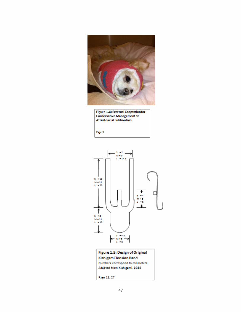
47

48

49

50
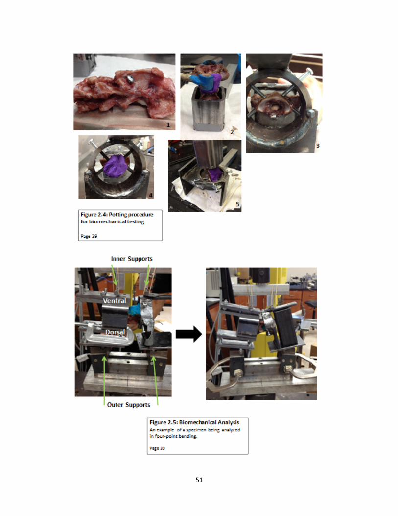
51
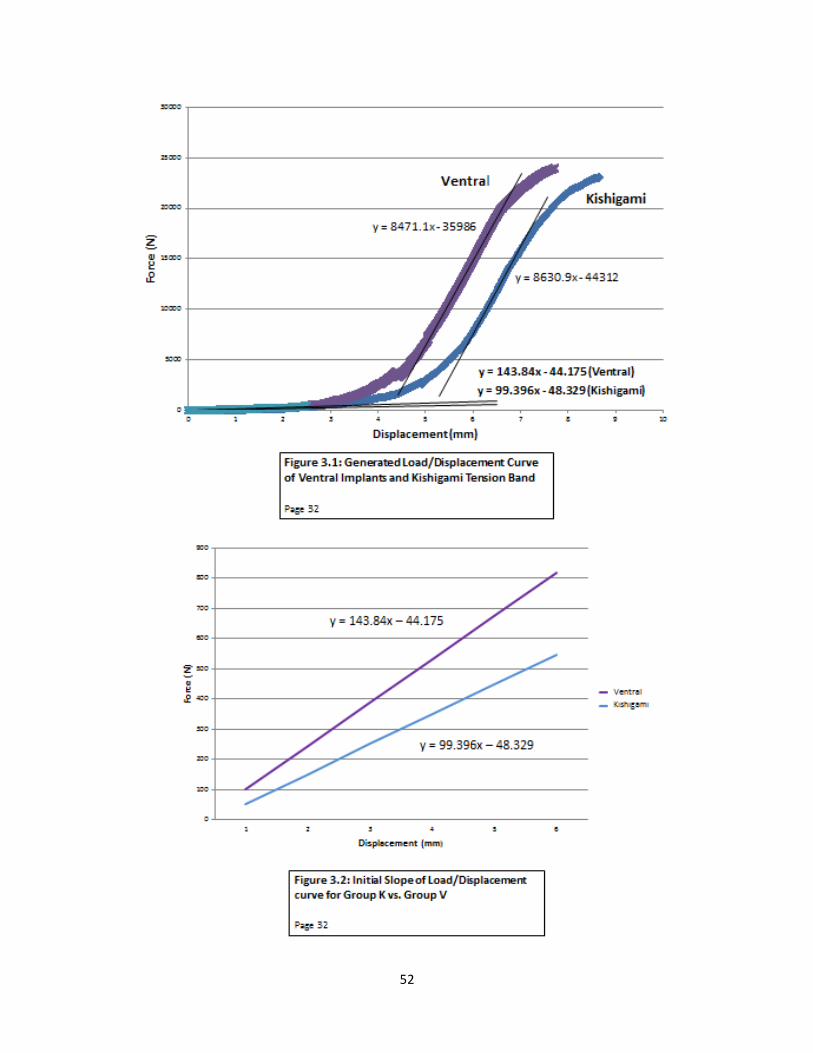
52

53
0
50
100
150
200
250
300
350
Kishigami Ventral
Min
Figure 3.3: Box Plot of Stiffness for Group K and Group V * = outlier Page 32
0
50
100
150
200
250
300
350
Group I Group M
Figure 3.5: Box Plot of Stiffness for Group I and Group M * = outlier Page 33

54
Tables
Table 2.1: Number of Specimens per Group Page 27 Skeletal Maturity Method of Stabilization Number of
specimens Group
Mature (M) Kishigami tension band (K) 4 KM Mature (M) Ventral pins and PMMA (V) 4 VM Immature (I) Kishigami tension band (K) 4 KI Immature (I) Ventral pins and PMMA (V) 5 VI
Table 3.1: Descriptive Statistics for Groups Page 32 Group Sample Size Mean Median Standard Deviation K 8 99.32 101.42 16.43 V 9 164.99 135.27 76.78 M 9 140.61 120.40 72.85 I 8 126.75 115.17 58.61
Table 3.2: Differences of Group Least Squares Means Page 32, 33 Group Group Estimate Standard Error DF t Value Pr > |t| Alpha
K V -‐0.4397 0.1543 14 -‐2.85 0.0129 0.05 I M -‐0.07382 0.1543 14 -‐0.48 0.6398 0.05
Table 3.3: Type III Tests of Fixed Effects Page 33 Effect Num DF Den DF F Value Pr > F Implant 1 13 7.85 0.0150 MI Group 1 13 0.24 0.6292
Implant*MI Group 1 13 0.30 0.5923
Table 3.4: Simple Effect Comparisons Implant*MI Group Least Squares Means by MIGroup Adjustment for Multiple Comparisons: Holm-‐Tukey Page 33 Simple Effect
Level Implant Implant Pr > |t| Adj P Alpha
MI Group I K V 0.0380 0.0380 0.05 MI Group M K V 0.1256 0.1256 0.05

55
Table 3.5: Simple Effect Comparisons Implant*MI Group Least Squares Means by Implant Adjustment for Multiple Comparisons: Holm-‐Tukey Page 33
Simple Effect Level
MI Group MI Group Pr > |t| Adj P Alpha
Implant K I M 0.4848 0.4848 0.05 Implant V I M 0.9690 0.9690 0.05