biogas brochure
TRANSCRIPT

Biogas Production � Safe and SustainableMeasurement and control system concepts from a single source


The Biogas BoomThe EU directive is being implemented differently in individual member states. The growing biogas market is developing almost exponentially within the countries in which the EU directive is being implemented using fixed price regulations. These countries include Germany, Austria and the new Eastern European EU member states. But even in countries outside of Europe comparable regulations exist, including Japan and the United States. Amidst the positive news, it is important to remember that Biogas plants also hold potential dangers for mankind and the environment. When it comes to safety, a clear trend is noticeable as lawmakers assign responsibility for plant safety to the plant
operators. The operator must assess, evaluate and control potential dangers using ap-propriate safety measures. It is clear that profitability be taken into account despite current subsidies to ensure that the biogas industry remains sustainable. All of this calls for a higher degree of plant control and intelligent measurement and control concepts that take into account the different aspects of� Plant safety� Plant availability � Keeping plants well balanced
This is providing solutions that ensure optimum operation for plant operators.
The current climate change discussion and increasing natural gas and fossil fuels prices are clear signs that we need to look for alternative energy supply strategies. As a result of the Kyoto protocol, the European Union adopted a directive to promote renewable energy sources. The aim is increasing the percentage of electrical power produced by renewables in the EU�s gross electrical power consumption from an average of 13.9% in 1997 to approximately 22% in 2010. This is to be the basis for doubling the percentage of renewables in the overall gross domestic energy consumption in the EU (including thermo-electric power and power consumption) to 12% by 2010.
3
DE
DK
UKIE
ES
FR
BE
NL
EU (25)
LU
IT
CZ
AT
SI
SK
HU
GR
RO1
BG1
LT*
LV*
MT* CY*
EE
FI
SE
PT
PL
5346,7
94,2
1923,2
33,3
63,5
1,3
93,8
59,9
118,1
8,4
10,5
4,8
69,4
353,8
227,0
334,39,2
34,7
1696,083,3
8,9
119,0
Map: Primary energy production of biogas of the European Union in 2006 (in KTOE/thousand tonnes of oil equivalent)
Landfill gas *Not significant Sewage sludge gas ¹ Bulgaria and Romania are not included in this survey Other biogases (agricultural waste, etc.) 33,3 Red figures show total production Source: EurObserve�ER 2007
The World of Endress+Hauser �People for Process Automation�
The Endress+Hauser Group Endress+Hauser is one of the leading international suppliers of measuring equipment, services and solutions for industrial process engineering. The company was established in 1953 by Georg H. Endress and Ludwig Hauser and has operated under the sole ownership of the Endress family since 1975. In 1995, Klaus Endress took over management of the Group from his father. In 2006, the Group of 7,045 employees generated �985.2 million in sales and �86.4 million in earnings. The family corporation includes 75 companies in 38 countries, managed and coordinated by a holding company in Reinach, Switzerland. Expert employees and partners guarantee global sales and service.
When the company was first established in 1953, Georg H. Endress laid down the company�s core values, which are still valid today: maintain a strict customer orientation, a high degree of knowledge and expertise in process measurement technology, a constant willingness to learn from our customers, and maintain communication, quality and a culture of innovation. These values played a key role in making Endress+Hauser one of the largest family companies today in the areas of industrial measurement technology and automation. Since its founding over 50 years ago, the company has developed from being a niche supplier of capacitive level measuring instruments to an international supplier of solutions, distinguishing itself internationally through a diverse product range of measuring instruments for process engineering.
InstrumentsEndress+Hauser provides a wide range of sensors, devices, systems and services for measuring level, flow, pressure and temperature as well as liquid analysis and measurement registration. The company also links field devices to process control systems and supports its customers with technological and logistical automation solutions. The products are setting standards in terms of quality and technology. In 2006, Endress+Hauser spent 8.0% of its revenues on research and development and applied for patents for 179 new developments.
We know your industry�s requirementsOur customers are predominantly from the chemical and petrochemical, pharmaceutical, food and beverage, pulp and paper, primaries, environmental, energy, oil and gas and renewable fuels industries. These diverse industries have very different measurement technology requirements. Thus, Endress+Hauser formed a team of specialists over ten years ago known as Industry Management, which focuses on the needs of individual industries. Our Industry Managers work together with leading suppliers in the individual industries. Today, they have the appropriate knowledge and expertise to help our customers operate a plant cost-effectively.
4

5
Expertise in Measurement TechnologyEndress+Hauser as a service provider
Engineering office/plant planner consulting for new installation and converted facility planningWe provide our customers with our knowledge and expertise as early as during the planning phase of the process or installation concept for new plants or plant sections. We are able to provide you with optimum, goal-oriented support as a result of our several years of experience in implementing measurement and control projects. Our core expertise includes PROFIBUS® engineering and the development of measurement technology plans, including layout.
Plant operator consultingEven for optimizing and renovating plants, we provide on-site consultation for issues relating to measurement technology design, migration planning (replacement) or improvement of existing measuring systems. The foundation for this is the Endress+Hauser �Installed Base Audit� (IBA) maintenance plan. This service includes assessing and evaluating the installed base and a maintenance plan based on this with recommendations for reducing the number of instrument types and stocking spare parts.
InstallationWe have system partners available for implementing planned installations who handle the entire range of electrical systems engineering and electrical installation services.
CommissioningMore safety for the plant operator is guaranteed through careful and professional commissioning of measuring equipment. This includes detailed inspection of installation, calibration and programming measuring equipment, and training operating personnel.
Maintenance and calibrationMaintenance contracts are discussed and agreed upon to ensure smooth plant operation. A complete range of maintenance support services is available to the operator, from simple functional testing to specific agreements. Maintenance of externally manufactured products can also be handled by arrangement.
Training and seminarsEndress+Hauser offers a large number of training programs and seminars. In addition to basic training on individual measuring principles, general as well as individually tailored training services are also available. Comprehensive topics, such as the ATEX directive and SIL (plant safety), fieldbus technologies and data communication, round off our seminar program.
A working measuring device does not guarantee that a measuring point is OK! Any expert can agree to this statement, most likely because of a lesson learned from their own experience. Choosing devices that are not ideally suited to the job during the planning phase, mistakes made during installation and commission-ing, and performing no maintenance or incorrect maintenance of equipment are all major causes of unsatisfactory measurement results. Endress+Hauser provides support at all phases in the measurement technology lifecycle, starting with plan-ning and extending to installation and commissioning and finally to operation, with a well-coordinated range of services.

6
Universal � Complete � SimpleMeasurement and control plans for the biogas industry
Making biogas production profitableDespite government subsidies, a biogas plant can only operate profitably under long running times. Currently, the average availability of biogas plants is estimated to be 60 to 65% and is thus below the percentage considered to be profitable, which is 80%. The reason for this insufficient plant availability is frequently due to lack of a measurement and control plan, which would allow for early interventions when there are negative changes in the status of fermentation. In this case, the issue is not only about operation of a measuring device or its technical properties. For the planning engineer, tasks regarding design and the correct selection of measuring principles play a decisive role. For the general business operator, who is responsible for coordinating different maintenance groups, the issue is about optimizing commissioning times as well as minimizing the cost of coordinating project events. Last but not least, the operator must be able to operate the plant efficiently, which means at a minimum cost. Here, aspects of training costs, replacement part storage and commissioning are crucial when assessing whether a measurement and control plan is to be valued as universal, complete and simple.
Biogas plant instrumentationDepending on the complexity and size of the plant, a more or less comprehensive measuring installation is important for monitoring and controlling central plant areas. Fermentation and biogas processing/CHP are the focus, since they have considerable influence over the plant�s entire efficiency.
Measuring equipment recommendations for biogas plants
Lqui
d m
anur
e,si
lage
)
Del
iver
y
Pret
reat
men
t
Ferm
ente
r
Gas
hol
der
Fina
l Sto
rage
Biog
as p
roce
ssin
g
Slud
ge tr
eatm
ent
Ther
mal
cyc
le
Exha
ust a
ir d
econ
t.Continuous level measurement, no contact with medium Radar
Ultrasonic
Continuous level measurement, contact with medium Pressure/hydrostatic
Level measurement as the level limit Capacitive
Vibration
Temperature measurement Pt 100
Pressure measurement Pressure
Differential pressure
Liquid flow measurement, volumetric Electromagnetic inductive
Biogas flow measurement, volumetric Dynamic pressure sensor/aperture
Biogas flow measurement, mass Thermal
Liquid analysis measurement technology Digital pH measurement
Measurement of solids
Measurement of acids

Measurement technology for reliable process controlExamples of typical measuring points at biogas plants
The biogas process can be monitored and controlled by determining a few critical parameters.The most important parameters include temperature, gas volume and pressure, methane content and hydrogen sulfide. In addition, the rate of flow of the substrate and the solid matter content are important variables for the holding time and volume
Level limit detection: Liquicap M and Liquiphant The preferred area of application for capacitive level measurement is in smaller tanks, where a level limit (min/max) or even a continuous measurement is required. Capacitance level is also the easier option for detecting the level limit in the fermenter. Integrated build-up compensation allows for a high degree of functionality, even when build-up is heavy. Shielding against condensation also provides a high degree of availability and ensures plant safety for the operator. A key advantage of the Liquiphant vibration limit switch is its calibration-free operation. Adaptation to different media is not necessary. The level limit is safely detected with hardly any influence from the physical properties of the medium.
Level measurement based on the Time-of-Flight principle (radar and ultrasonic): Micropilot and Prosonic Both radar and ultrasonic level measurements are non-contact measuring systems. The advantage is that the sensor does not come into contact with the medium, eliminating negative influences and potential contamination. Both systems measure the time difference between the signal sent from the sensor and the signal being received after reflection on the surface of the material being measured. Ultrasonic devices generate ultrasonic waves, while radar devices produce and use radar pulses to measure level. The advantage of radar measurement is that measurement is not affected when gas composition, pressures and temperatures are variable. A typical application for a radar measuring device detecting foam in the fermenter. The less expensive ultrasonic method is used extensively in all types of collection tanks and feeding systems.
7
Level limit in hygienization: Liquiphant M Level limit in fermenter: Liquicap M
load in the fermenter. For additional process management, there are also level measurements, in collecting tanks (hygienization, suspension), in fermenters (foam detection) and even in gathering systems (screw conveyors, conveying equipment). All of these parameters can be continuously measured and evaluated using electronic measurement technology.
1 2
3
1
3 Gas holder (post-fermenter) level measurement by sensing the position of the pendulum (Prosonic M)
Measurement of level in batch usingUltrasonic device (Prosonic M)
2 Continuous level measurement in fermenter usingRadar: Micropilot M

Electromagnetic induction flow measurement of liquids: Proline Promag 50W/55SThe electromagnetic induction flow measurement principle has been frequently tested and is widely used throughout the process industry. Electromagnetic devices have a high degree of accuracy (0.5 to 0.2%), cause no loss in pressure and are also suitable for solid suspensions, which can occur in renewable primary product plants. These flowmeters are ideal for detecting substrate solutions and for balancing. These highly sophisticated transmitters also have integrated extensive diagnostic capabilities and contribute to increased process safety.
Renewable primary products
Fermenter
Dry fermentation
Wet fermentationRenewable primary products
Liquid manure Homogenization Hygienization
Liquid manure
Out
Measurement of entered volume: Proline Promag

Fermenter
Post-fermenter
tput
Output
Flow measurement for biogas: Deltatop/Deltaset and Proline t-mass 65 Measuring the volume of biogas is important for operation and poses a challenge in terms of measurement technology and planning. This challenge is due to the nature of the process and the characteristics of biogas that are linked to this process: extremely variable biogas production requires a high dynamic measuring range. The variable composition and moisture load of biogas as well as the issue of minimized pressure losses are aspects to be considered when selecting the best measuring principle. It is critical to work with a partner who is able to provide different methods for measuring the volume of biogas. Endress+Hauser has a variety of physical measurement methods available. The method usually used for measuring the volume of biogas includes a dynamic pressure sensor or aperture (pressure differential), or the thermal measuring principle can be used.
Biogas utilization
Measuring biogas mass: t-mass in inlet to CHP system

Temperature measurement: OmnigradIn addition to the volume of organic acids and the pH value, temperature is the most important parameter for the microbial breakdown process into biogas and is usually measured in every fermenter. Endress+Hauser has a wide range of temperature sensors available. Omnigrad resistance thermometers (PT100) are usually used for biogas plants. This thermometer has a measuring probe with a protective well and a connecting head that contains a transmitter. Since the immersion length and process connections are adjustable, the temperature sensors can be easily tailored to the customer�s requirements.
Pressure measurement: Cerabar and DeltabarPressure measurement requirements can vary depending on the insertion site and measurement task. The range of pressure sensors made by Endress+Hauser is organized accordingly: from simple pressure switches to high-precision pressure sensors. The pressure measurement in biogas plants is usually taken in the biogas line to check the compression output, but it is also used for hydrostatic level measurement in collection tanks or fermenters. Even biogas metering using a dynamic pressure sensor or aperture utilizes a pressure differential measurement that must be extremely accurate due to the very low pressure differences.
Measurement technology analysis for biogas plants: Liquisys M-series for measuring solids, acids and pHIn some biogas plants, there is a need to measure the pH due to the significance of the parameter for microbial breakdown. However, the pH can provide only partial information on the existing concentration of organic acids due to the high buffering capacity of the fermenter suspension. Measuring solids in connection with the suspension volume provides information on the fermenter�s volume load and can help make the process more efficient. Measuring acids for biogas desulphurization is recommended, where the hydrogen sulfide is converted to sulfur by adding air.
8
Measuring temperature in fermenter: Omnigrad
Measuring pressure in biogas line: Cerabar
pH measurement (left) and solid matter measurement (right) with Liquisys transmitter, sensors and process fitting

9
Universal � Complete � Simple Measurement and control plan for the biogas industry
Endress+Hauser is investing in the research and development of new and innovative measuringmethods. Measurement is our core competence and we use our expertise each day to help our customers. We work closely with our customers to understand their special challenges. We use this information with our development specialists to invent new and better instrumentation designed to meet or exceed our customer�s needs.
Level:Micropilot � non-contact radar level meas-urement is not affected by pressure and temperature fluctuations. Ideally suited for level detection in the fermenter; certified for use in zones 0 and 1.
Level:Prosonic M/S � non-contact level measure-ment using ultrasonic technology features envelope curve evaluation and integrated temperature measurement for time-of-flight correction to ensure a high degree of operating safety. Ideal for measuring liquids and silages; certified for Ex zones.
Level:Multicap T � continuous level measuring, especially for small tanks offers reliable functionality due to active build-up com-pensation as well as shielding against con-densation build-up in the connecting pipe.
Temperature:Omnigrad resistance thermometer � ideal for liquid, solid and gaseous media provides excellent price/performance ratio. Certified for Ex zones.
Registration:Memograph � videographic recorder with adjustable sets of parameters guarantees data secure from manipulation: TÜV tested, remote alarm via Telealarm software.
Flow: Proline Promag � high-precision, solid and reliable electromagnetic inductive flow measurement with abrasion-resistant hous-ing, even for sludge that contains particu-lates (15 to 20%).
Flow:Proline t-mass � thermal flow metering for biogas (behind dryer). High dynamic meas-uring range and a high degree of accuracy even at the lowest pressures.
Flow:Deltatop/Deltaset � flow measurement with restrictors or dynamic pressure sensor measurement for gaseous media. Includes pressure and temperature correction for detecting Nm3.
Analysis: Liquisys M � a device for all important analysis parameters, completed by a wide range of fittings.

10
From Sensor to SolutionAutomation solutions from Endress+Hauser
Since the introduction of communication technologies more than a decade ago, the barriers between field instrumentation and the system level began to disappear. The instruments became more intelligent and an integral part of the automation architecture. Endress+Hauser recognized this trend and has been actively involved in different standardizing bodies and user organizations since the beginnings of fieldbus technology. We support technologies established in the market and are actively engaged with emerging integration technologies, like FDT. We offer comprehensive engineering services for the integration of field instruments into all relevant control and asset management systems in process industry.
Process control and regulation through ControlCareControlCare is an open, field-based process control platform. It takes full advantage of intelligent fieldbus devices, exploiting their ability to provide extended information about themselves, the process and the plant. ControlCare uses standardized function blocks that can be easily combined, confi-gured and expanded. The open architecture, based on modular components, provides the freedom to choose components and suppliers for the most cost-effective solution. Open standards and protocols are used at all levels � from measuring device to system � for communication, data access, configura-tion and diagnosis� Device and process information is
available at every point in the system � Plant information is available where and
when it is needed� Simple system integration� Easily scalable
SCADA integration for operation and observationControlCare uses state-of-the-art technolo-gies to ensure ease of SCADA integration. � OPC client/server architecture makes
communication efficient: all process data are brought together into a single data-base.
� ControlCare P View offers all of the functions of a current SCADA software package for operation and observation. P View communicates with the process by way of OPC interfaces. The integrated Web server creates the foundation for distributed operation and observation, visualization and monitoring.
� FieldCare, an FDT based tool, allows for setup of a parallel or integrated plant-ori-ented asset management system.
� XML-integrated process data in MS Office� and commercial applications

From Sensor to SolutionEndress+Hauser as a system integrator for the biogas industry
Process monitoringFor process monitoring and system optimization, measuring devices are integrated at points relevant to the process. This includes input material flow measurements (holding time and volume load), temperature and pH measurements in the fermenter, level measurements in collection tanks and flow and pressure measurements in the biogas line. The entire system is automated via four process controls from different suppliers (hygienization, fermentation pipes, CHP system and internal technology). Endress+Hauser handled the overall metrological plan for the system as well as the linking of the four process controls using the P View visualization system. In addition to linking and data access from the four controls, the P View visualization system took over the following tasks: � Visualization of the process� Constant monitoring of critical
system views� Alert via e-mail for threshold violations� Remote access to visualization system
for servicing
One of the first projects using the Endress+Hauser SCADA system was an industrial biogas plant built in southern Germany in 2002 for generating electricity and heat from food waste. The plant generated approximately 2,900 MWh of electricity and 3,500 MHw of heat annually from approximately 8,000 t of food waste.
The process The substrate delivered in a sump is pumped into four fermentation pipes after one hour of hygienization at 70º C and then fermented under mesophilic conditions. The remaining biogenous material is transferred via a post-fermenter to final storage. The heavily loaded wastewater is treated via a wastewater treatment plant. The resulting biogas is delivered to the CHP system after drying and desulphurization. All of the resulting electricity is fed into the network; the heat is used to heat the fermenter, including hygienization.
pH measurement in the supply line to the fermenter: Liquisys M transmitter
Fermentation
Visualization of the sump and hygienization Hygienization system
11
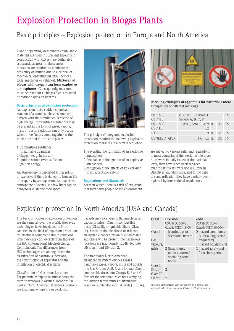
Plant or operating areas where combustible materials are used in sufficient amounts in conjunction with oxygen are designated as hazardous areas. In these areas, measures are required to eliminate the possibility of ignition due to electrical or mechanical operating material (devices, tools, machines or vehicles). Mixtures of biogas with oxygen can form explosive atmospheres. Consequently, measures must be taken for all biogas plants to avoid or reduce explosion hazards.
Basic principles of explosion protectionAn explosion is the sudden chemical reaction of a combustible substance with oxygen with the simultaneous release of high energy. Combustible substances may be present in the form of gases, vapors, mists or dusts. Explosion can only occur, when three factors come together at the same time and in the same place:
1. Combustible substance (in ignitable quantities)
2. Oxygen (e. g. in the air)3. Ignition source (with sufficient
ignition energy)
An atmosphere is described as hazardous or explosive if there is danger to human life or property by an explosion. An explosive atmosphere of even just a few liters can be dangerous in an enclosed space.
Explosion Protection in Biogas PlantsBasic principles � Explosion protection in Europe and North America
The principle of integrated explosion protection requires the following explosion protection measures in a certain sequence.
1. Preventing the formation of an explosive atmosphere
2. Avoidance of the ignition of an explosive atmosphere
3. Mitigation of the effects of an explosion to an acceptable extent
Regulations and StandardsAreas in which there is a risk of explosion that may harm people or the environment
are subject to various rules and regulations in most countries of the world. While these rules were initially issued at the national level, they have since been replaced over the last years by regional European Directives and Standards, and in the field of standardization they have partially been replaced by international regulations.
Marking examples of apparatus for hazardous areasComparison of different markings
NEC 500CEC J18
IS, Class I, Division 1, Groups A, B, C, D
T6
NEC 505CEC 18
Class I, Zone 0, AExEx
ia IIC T6
IEC Ex ia IIC T6CENELEC (ATEX) II 1 G Ex ia IIC T6
12
The basic principles of explosion protection are the same all over the world. However, technologies have developed in North America in the field of explosion protection for electrical equipment and installations which deviate considerably from those of the IEC (International Electrotechnical Commission). The differences from IEC technologies are among others the classification of hazardous locations, the construction of apparatus and the installation of electrical systems.
Classification of Hazardous LocationsFor potentially explosive atmospheres the term �hazardous (classified) locations� is used in North America. Hazardous locations are locations, where fire or explosion
hazards may exist due to flammable gases, vapors or mists (Class I), combustible dusts (Class II), or ignitable fibers (Class III). Based on the likelihood or risk that an ignitable concentration of a flammable substance will be present, the hazardous locations are traditionally subdivided into Division 1 and Division 2.
The traditional North American classification system divides Class I flammable gases, vapors, mists and liquids into Gas Groups A, B, C and D, and Class II combustible dusts into Groups E, F and G. Further the temperature codes classifying the ignition temperatures of flammable gases are subdivided into 14 levels (T1�T6).
Class DivisionUSA (NEC 500-5), Canada (CEC J18-004)
ZoneUSA (NEC 505-7), Canada (CEC 18-006)
Class I
Gas,vapours,mists
1 (continuous or occasional hazard)
0 (hazard continuous-ly, for a long period, frequently)
1 (hazard occasionally)2 (hazard only
under abnormal operating condi-tions)
2 (hazard rarely and for a short period)
Class IIDusts
12
Class IIIFibres
12
The zone classification was introduced as a parallel sys-tem to the division system for Class I in North America.
Explosion protection in North America (USA and Canada)

The Directive 94/9/EC (ATEX 95)The EC Directive 94/9/EC was issued in 1994 to further standardize explosion protection and make corresponding adjustments in line with a new directive approach. It specifies the requirements for explosion protected equipment and protective systems by prescribing essential health and safety requirements. It guarantees free trade within the European Community, as agreed in Article 95 of the Treaty established between the European Community member states. The term ATEX is the abbreviation of the French designation for explosive atmosphere �ATmosphère EXplosible�.
The directive had to be implemented into national law without any changes/exceptions. The scope covers all electrical and non-electrical equipment, and protective systems for use in potentially explosive atmospheres.
Equipment categories: The manufacturer of equipment that includes their own potential ignition sources, and therefore can cause an explosion, have to ensure that the equipment undergoes an ignition hazard assessment procedure, and takes measures according to the essential safety requirements to exclude the risk of ignition. In the directive, Group I apparatus (Surface and Underground Mining Systems) are divided into two categories and Group II apparatus (other explosive areas) are divided in three categories with various levels of safety (see table).
Categories of Group II apparatus: Other Explosive Areas
Category 1 Category 2 Category 3
Very high degree of safety High degree of safety Normal degree of safety
Safe even when two faults occur independently
Safe even when a fault occurs
Safe during normaloperation
The Directive 1999/92/EC (ATEX 137)The 1999/92/EC Directive states �Mini-mum requirements for improving the health and safety protection of worker potentially at risk from explosive atmospheres� refers to the operation of potentially explosive installations, and is therefore intended for the employer. This directive contains only minimum requirements. When implment-ing it into national law, the single states can adopt further regulations. According to the 1999/92/EC Directive, it is the duty of the employer to verify where there is a risk of explosion, classify the hazardous areas into zones accordingly, and document all measures taken to protect the personnel in the explosion protection documents.
Anywhere in the world that a Biogas plant will be constructed or maintained, Endress+Hauser can deliver the best instruments with right certificates.
Zones and allocation of equipment according to the category
Zone Duration of occurrence of an explosive atmosphere
Equipment category
Gas, vapors, mists
0 continuously, for a long period, frequently
1G
1 occasionally 2G OR 1G
2 rarely and for a short period 3G OR 2G OE 1G
Dusts 20 continuously, for a long period, frequently
1D
21 occasionally 2D or 1D
22 rarely and for a short period 3D* or 2D or 1D (* non conductive dusts only)
13
The table contains an overview of the zones for explosion protection and allocation of equipment according to the category.
Explosion protection in Europe
Assessment of explosion risksWhen assessing the risks of explosion, the following factors are to be taken into account:� the likelihood that explosive atmospheres
will occur and their persistence� the likelihood that ignition sources,
including electrostatic discharges, will be present and become active and effective
� the installations, substances used, pro-cesses, and their possible interactions
� the scale of the anticipated effects
Zone classificationThe employer has to classify the areas in which explosive atmospheres may be present into zones, and to ensure that the minimum organizational and technical requirements of the Directive are observed.Flammable gases are classified into the ex-plosion groups IIA, IIB and IIC depending on their ignition energy. Six temperature classes (T1�T6) classify the ignition temperatures of flammable gases. The explosion group and temperature class of used apparatus has to be equal or higher than the classification of the ambient flammable gases.
Types of Protection Only explosion protected equipment may be used in areas in which an explosive at-mosphere may still be expected despite the implementation of prevention measures.
Example: Biogas explosion hazardMethane is the flammable part of biogas. For its Ignition temperature 537 °C Temperature class T1Ignition energy 280 μJ Explosion group IIA/Gas Group D
100%
70%
50%
0%
0%
30%
50%
100%
Bio-Gas
Carbon dioxide CO2no ignition it´s inert
Methane CH4Tignition = 537 °C T1Eignition = 280 μJ IIA
Bio-Gaswith
Oxygen>11.6%
Danger explosion!

Instruments International
Endress+Hauser Instruments International AGKaegenstrasse 24153 ReinachSwitzerlandTel. +41 61 715 8100Fax +41 61 715 2500http://[email protected]
01.07/MMC
SO 705B/11/en/09.0771062957INDD CS2
Additional information� Brochure Competence in renewable fuels Managing ethanol and biodiesel process measuremt
safely, reliably and profitably � from load-in to load-out SO 050B/24/ae
� Poster Explosion Protection Marking Overview CP 001Z/11/en