bin-wall retaining wall product guide - armtec · pdf filearmtec drainage solutions | bin-wall...
TRANSCRIPT
–
DRAINAGE SOLUTIONSSINCE 1908
BIN-WALL RETAINING WALLProduct GuideBIN-TYPE RETAINING WALLS
–
VERSATILE
DURABLE
ECONOMICAL
EASY TO INSTALL
2 VISIT ARMTEC.COM FOR MORE INFORMATION
VERSATILE DURABLE EASY INSTALLATION ECONOMICAL
• Its modular design is suitable for a wide variety of applications and configurations
• Withstands temperature variations and accommodates minor ground movement
• Installed without expensive lifting equipment and with minimal excavation
• Lightweight, nested components allow for economical shipping over long distances
TYPICAL APPLICATIONS
• Slope retention
• Highway or railway right-of-way enlargement
• Docks and piers at freshwater marinas
• Solid waste transfer units
• Blast walls (military applications)
• Industrial and commercial developments
• Wing walls and bridge abutments
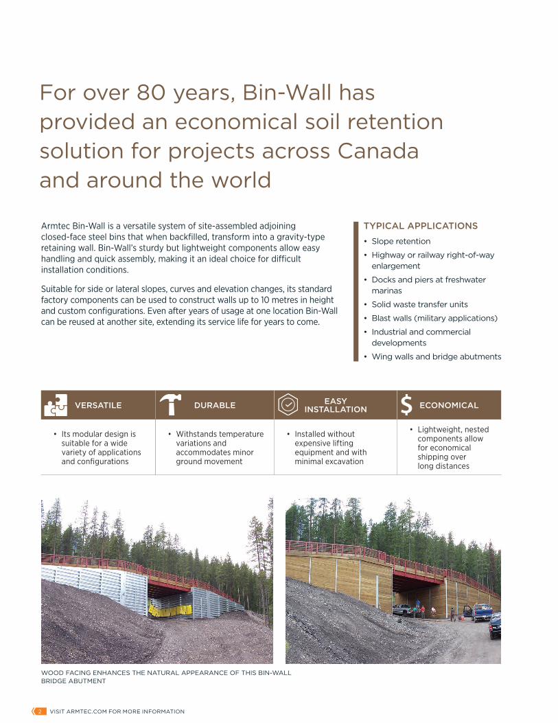
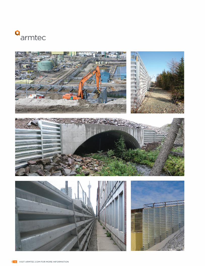
Armtec Bin-Wall is a versatile system of site-assembled adjoining closed-face steel bins that when backfilled, transform into a gravity-type retaining wall. Bin-Wall’s sturdy but lightweight components allow easy handling and quick assembly, making it an ideal choice for difficult installation conditions.
Suitable for side or lateral slopes, curves and elevation changes, its standard factory components can be used to construct walls up to 10 metres in height and custom configurations. Even after years of usage at one location Bin-Wall can be reused at another site, extending its service life for years to come.
WOOD FACING ENHANCES THE NATURAL APPEARANCE OF THIS BIN-WALL BRIDGE ABUTMENT
For over 80 years, Bin-Wall has provided an economical soil retention solution for projects across Canada and around the world.
ARMTEC DRAINAGE SOLUTIONS | BIN-WALL 3
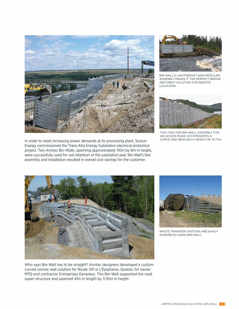
WASTE TRANSFER STATIONS ARE EASILY ASSEMBLED USING BIN-WALL
BIN-WALL’S LIGHTWEIGHT AND MODULAR ASSEMBLY MAKES IT THE PERFECT BRIDGE ABUTMENT SOLUTION FOR REMOTE LOCATIONS
THIS TWO-TIER BIN-WALL ASSEMBLY FOR AN ACCESS ROAD ACCOMODATES A CURVE AND REACHES A HEIGHT OF 10.77mIn order to meet increasing power demands at its processing plant, Suncor
Energy commissioned the Trans-Alta Energy Substation electrical protection project. Two Armtec Bin-Walls, spanning approximately 110m by 8m in height, were successfully used for soil retention of the substation pad. Bin-Wall’s fast assembly and installation resulted in overall cost savings for the customer.
Who says Bin-Wall has to be straight? Armtec designers developed a custom curved convex wall solution for Route 341 in L’Épiphanie, Quebec for owner MTQ and contractor Entreprises Genereux. This Bin-Wall supported the road super-structure and spanned 41m in length by 3.35m in height.
4 VISIT ARMTEC.COM FOR MORE INFORMATION
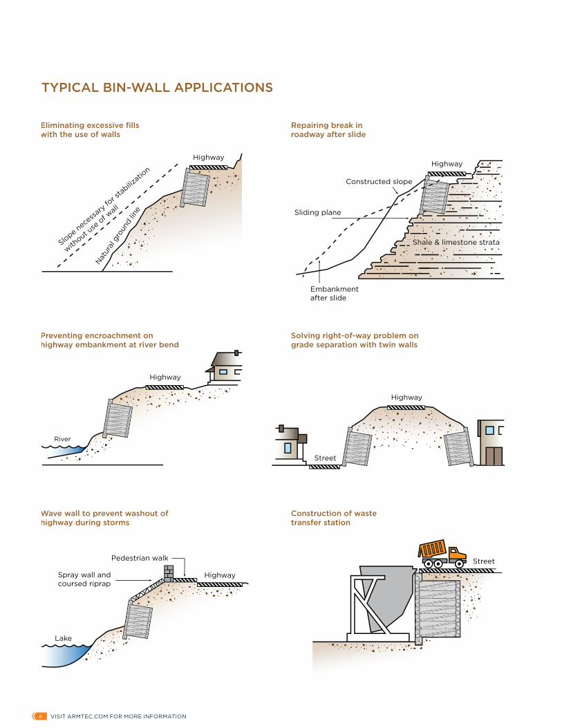
Solving right-of-way problem ongrade separation with twin walls
Highway
Street
Preventing encroachment on highway embankment at river bend
Highway
River
Eliminating excessive fills with the use of walls
Highway
Nat
ural
gro
und
line
Slope necess
ary fo
r sta
bilizat
ion
without u
se of w
all
Wave wall to prevent washout of highway during storms
Repairing break in roadway after slide
Construction of waste transfer station
Street
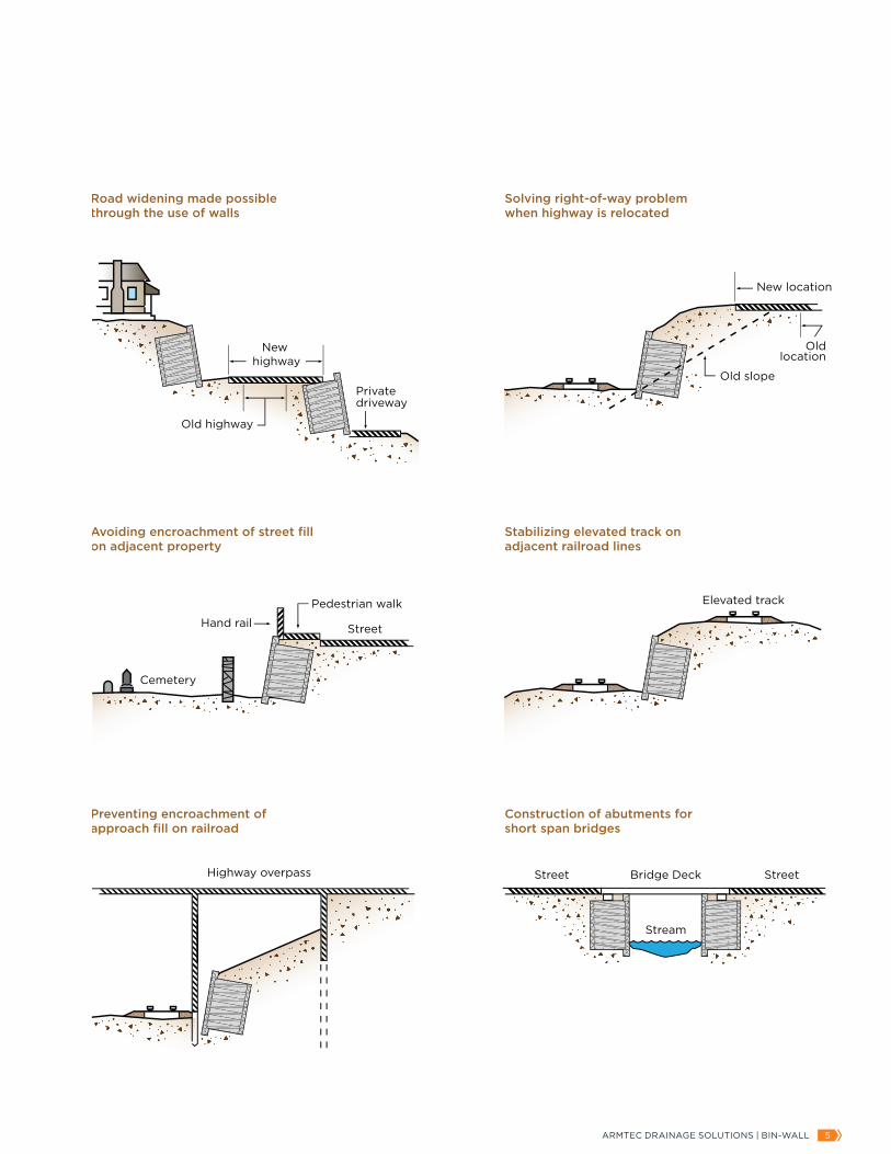
TYPICAL BIN-WALL APPLICATIONS
Shale & limestone strata
Constructed slope
Sliding plane
Embankment after slide
Highway
Lake
Highway
Pedestrian walk
Spray wall andcoursed riprap
ARMTEC DRAINAGE SOLUTIONS | BIN-WALL 5
Construction of abutments forshort span bridges
Stream
Bridge DeckStreet Street
Avoiding encroachment of street fillon adjacent property
Cemetery
Hand rail
Pedestrian walk
Street
Stabilizing elevated track onadjacent railroad lines
Elevated track
Preventing encroachment ofapproach fill on railroad
Highway overpass
Solving right-of-way problemwhen highway is relocated
Road widening made possible through the use of walls
New highway
Private driveway
Old highway
Old slope
New location
Oldlocation
6 VISIT ARMTEC.COM FOR MORE INFORMATION
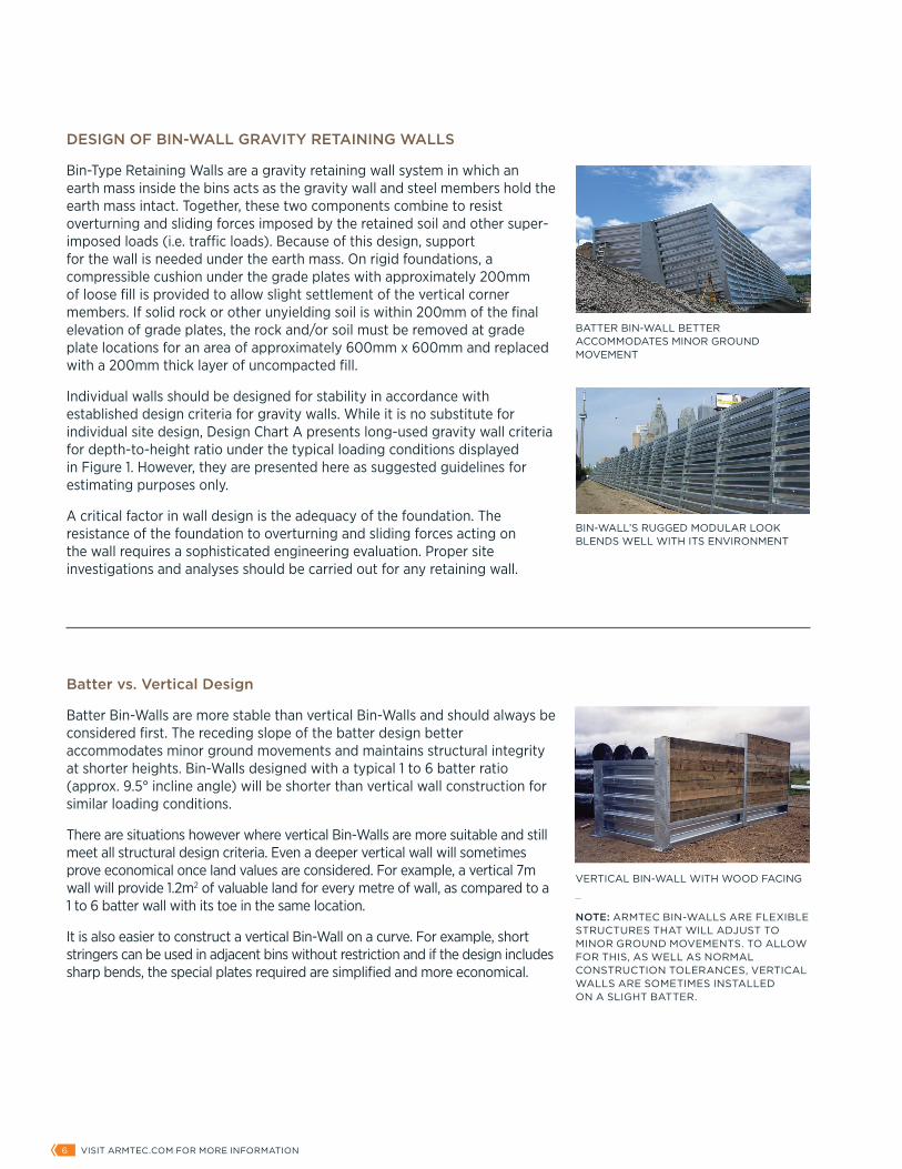
DESIGN OF BIN-WALL GRAVITY RETAINING WALLS
Bin-Type Retaining Walls are a gravity retaining wall system in which an earth mass inside the bins acts as the gravity wall and steel members hold the earth mass intact. Together, these two components combine to resist overturning and sliding forces imposed by the retained soil and other super-imposed loads (i.e. traffic loads). Because of this design, support for the wall is needed under the earth mass. On rigid foundations, a compressible cushion under the grade plates with approximately 200mm of loose fill is provided to allow slight settlement of the vertical corner members. If solid rock or other unyielding soil is within 200mm of the final elevation of grade plates, the rock and/or soil must be removed at grade plate locations for an area of approximately 600mm x 600mm and replaced with a 200mm thick layer of uncompacted fill.
Individual walls should be designed for stability in accordance with established design criteria for gravity walls. While it is no substitute for individual site design, Design Chart A presents long-used gravity wall criteria for depth-to-height ratio under the typical loading conditions displayed in Figure 1. However, they are presented here as suggested guidelines for estimating purposes only.
A critical factor in wall design is the adequacy of the foundation. The resistance of the foundation to overturning and sliding forces acting on the wall requires a sophisticated engineering evaluation. Proper site investigations and analyses should be carried out for any retaining wall.
Batter vs. Vertical Design
Batter Bin-Walls are more stable than vertical Bin-Walls and should always be considered first. The receding slope of the batter design better accommodates minor ground movements and maintains structural integrity at shorter heights. Bin-Walls designed with a typical 1 to 6 batter ratio (approx. 9.5° incline angle) will be shorter than vertical wall construction for similar loading conditions.
There are situations however where vertical Bin-Walls are more suitable and still meet all structural design criteria. Even a deeper vertical wall will sometimes prove economical once land values are considered. For example, a vertical 7m wall will provide 1.2m2 of valuable land for every metre of wall, as compared to a 1 to 6 batter wall with its toe in the same location.
It is also easier to construct a vertical Bin-Wall on a curve. For example, short stringers can be used in adjacent bins without restriction and if the design includes sharp bends, the special plates required are simplified and more economical.
BATTER BIN-WALL BETTER ACCOMMODATES MINOR GROUND MOVEMENT
VERTICAL BIN-WALL WITH WOOD FACING
BIN-WALL’S RUGGED MODULAR LOOK BLENDS WELL WITH ITS ENVIRONMENT
_
NOTE: ARMTEC BIN-WALLS ARE FLEXIBLE STRUCTURES THAT WILL ADJUST TO MINOR GROUND MOVEMENTS. TO ALLOW FOR THIS, AS WELL AS NORMAL CONSTRUCTION TOLERANCES, VERTICAL WALLS ARE SOMETIMES INSTALLED ON A SLIGHT BATTER.
ARMTEC DRAINAGE SOLUTIONS | BIN-WALL 7
BIN
HE
IGH
T
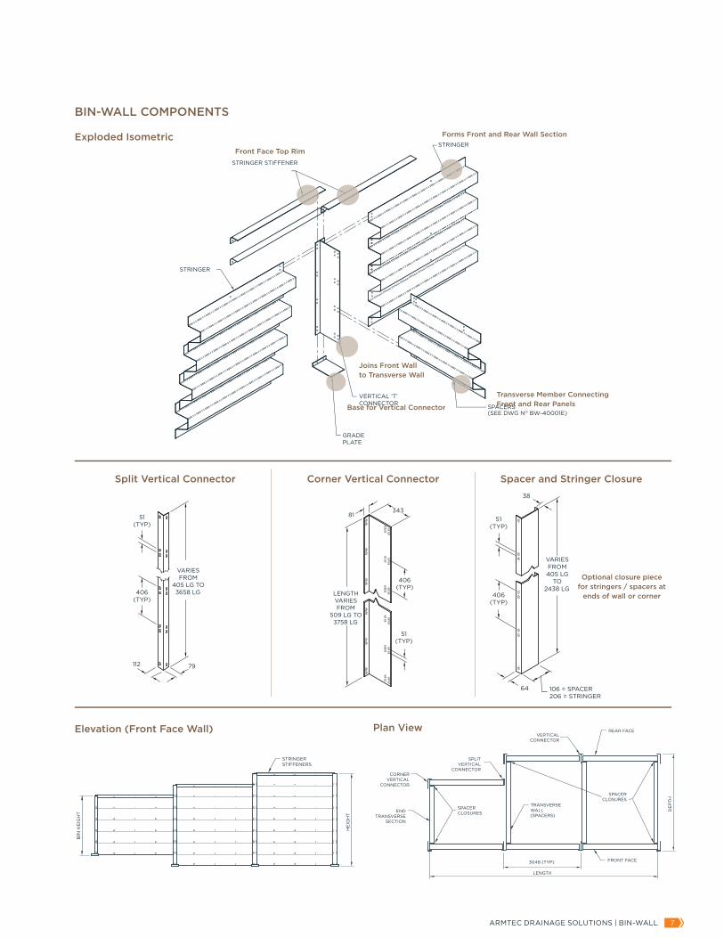
CORNERVERTICAL
CONNECTOR
FRONT FACE
TRANSVERSEWALL(SPACERS)
REAR FACEVERTICAL
CONNECTOR
SPACERCLOSURESEND
TRANSVERSESECTION
SPLITVERTICAL
CONNECTOR
SPACERCLOSURES
STRINGERSTIFFENERS
3048 (TYP)
HE
IGH
T
LENGTH
DE
PT
H
BIN
HE
IGH
T
CORNERVERTICAL
CONNECTOR
FRONT FACE
TRANSVERSEWALL(SPACERS)
REAR FACEVERTICAL
CONNECTOR
SPACERCLOSURESEND
TRANSVERSESECTION
SPLITVERTICAL
CONNECTOR
SPACERCLOSURES
STRINGERSTIFFENERS
3048 (TYP)
HE
IGH
T
LENGTH
DE
PT
H
VARIESFROM405 LG
TO2438 LG
106 = SPACER206 = STRINGER
SPACER ANDSTRINGER CLOSURE
38
51(TYP)
406(TYP)
64
STRINGER STIFFENER
STRINGER
STRINGER
VERTICAL ‘T’CONNECTOR
GRADE PLATE
SPACERS(SEE DWG NO BW-40001E)
BIN-WALL COMPONENTS
Plan View
Exploded Isometric
Elevation (Front Face Wall)
Split Vertical Connector Corner Vertical Connector Spacer and Stringer Closure
81 343
51(TYP)
406(TYP)
LENGTHVARIESFROM
509 LG TO3758 LG
CORNERVERTICAL CONNECTOR
51(TYP)
406(TYP)
79112
VARIESFROM
405 LG TO3658 LG
SPLIT VERTICAL CONNECTOR
Front Face Top Rim
Forms Front and Rear Wall Section
Transverse Member Connecting Front and Rear Panels
Optional closure piece for stringers / spacers at
ends of wall or corner
Joins Front Wallto Transverse Wall
Base for Vertical Connector

8 VISIT ARMTEC.COM FOR MORE INFORMATION
R =WALL DEPTH
WALL HEIGHT= D D
H
H
BATTER
WALL ON1:6
BATTER
WALL VERTICAL
LEVELSLIGHT WITH
SUPERIMPOSED LOADSLOPING TO
3 X DSLOPING ABOVE
3 X D
(R= .45) (R= .50) (R= .55) (R= .60)
(R= .55) (R= .60) (R= .65) (R= .70)
Figure 1: Loading condition (1-6) for batter and vertical wall designs
Preliminary design of Bin-Wall gravity retaining walls is performed by using the following procedure:
1. Select the loading condition (1 – 6) for the batter or vertical wall design using Figure 1.
2. Using the approximate height of the wall (H) use Chart A to determinethe corresponding wall design (depth) for your given loading condition. Wall designs are outlined in Figure 2.
Chart A: Wall height vs. wall design (depth)
Wall height: 3500mm
Loading Condition: 5
Wall Design: C
Actual Height: 3758mm Wal
l Hei
ght
Wall DESIGN (Depth)
For example:
Bin-Wall’s unique design allows it to fl ex against minor,
unforeseen ground movements that might damage or
destroy rigid walls.
ARMTEC DRAINAGE SOLUTIONS | BIN-WALL 9
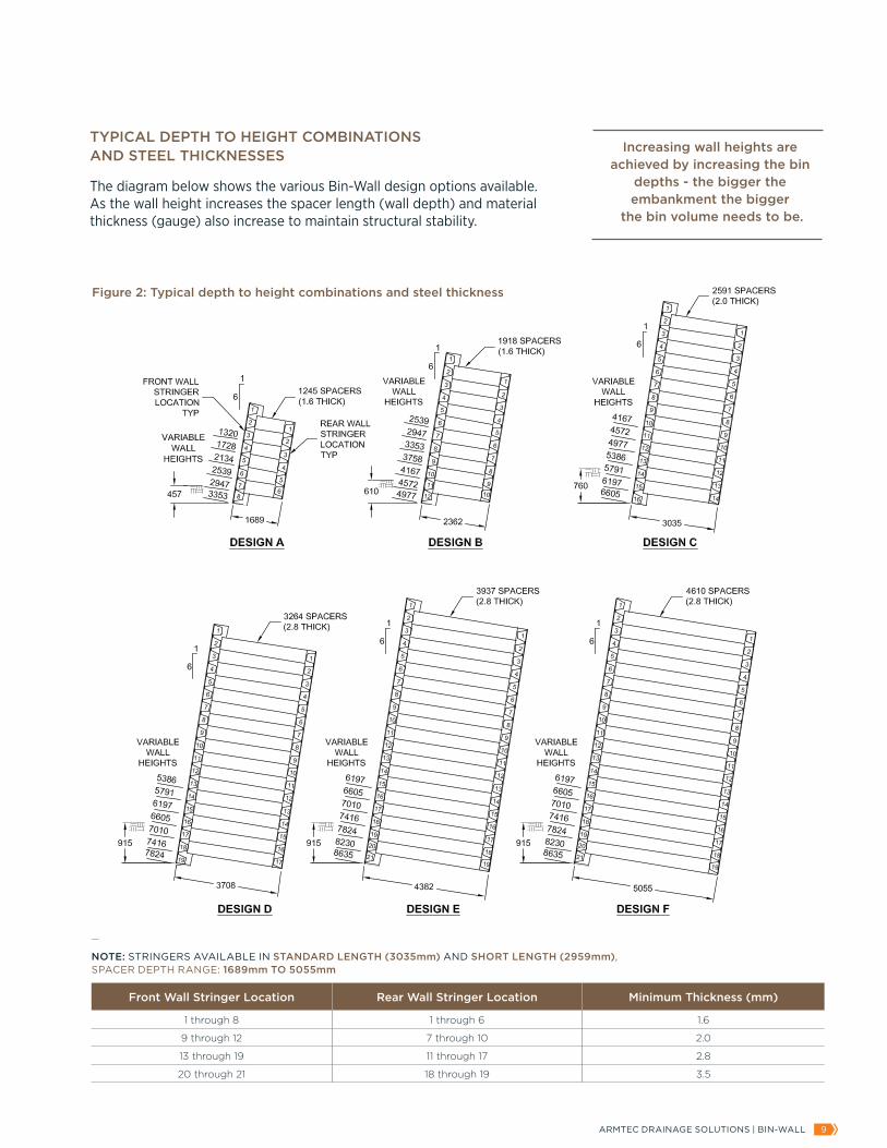
Figure 2: Typical depth to height combinations and steel thickness
TYPICAL DEPTH TO HEIGHT COMBINATIONS AND STEEL THICKNESSES
The diagram below shows the various Bin-Wall design options available. As the wall height increases the spacer length (wall depth) and material thickness (gauge) also increase to maintain structural stability.
Front Wall Stringer Location Rear Wall Stringer Location Minimum Thickness (mm)
1 through 8 1 through 6 1.6
9 through 12 7 through 10 2.0
13 through 19 11 through 17 2.8
20 through 21 18 through 19 3.5
_
NOTE: STRINGERS AVAILABLE IN STANDARD LENGTH (3035mm) AND SHORT LENGTH (2959mm), SPACER DEPTH RANGE: 1689mm TO 5055mm
Increasing wall heights are achieved by increasing the bin
depths - the bigger the embankment the bigger
the bin volume needs to be.
10 VISIT ARMTEC.COM FOR MORE INFORMATION
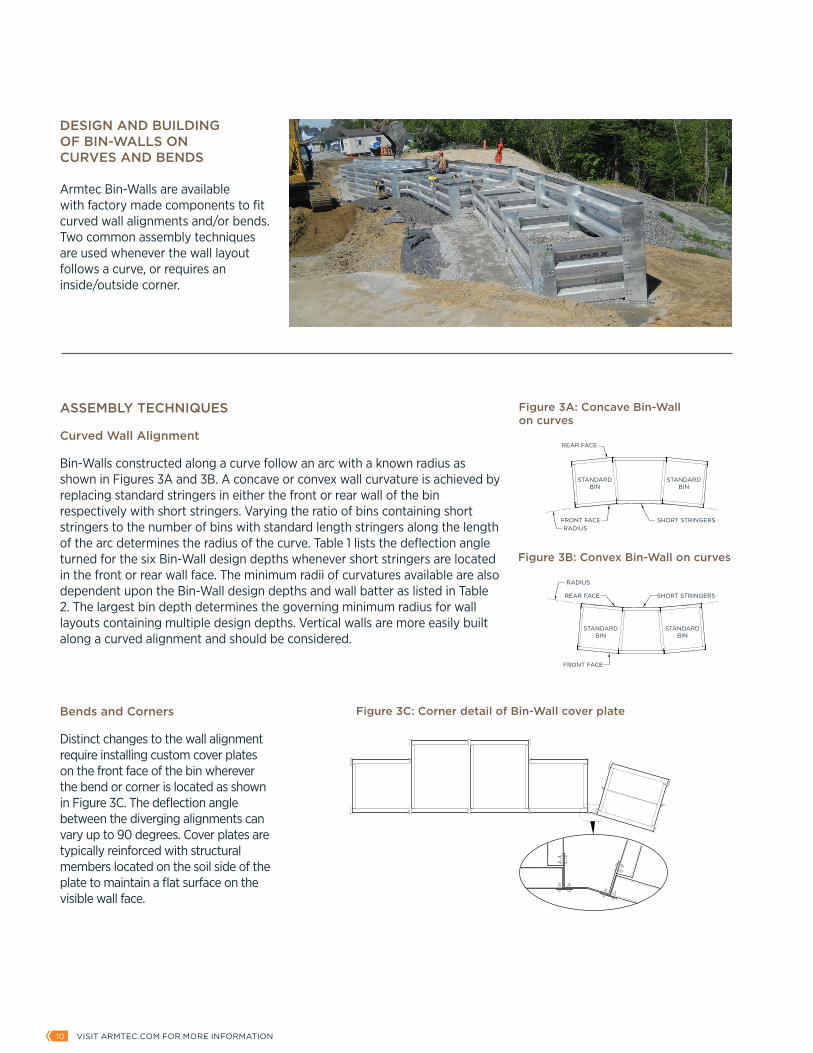
Armtec Bin-Walls are available with factory made components to fit curved wall alignments and/or bends. Two common assembly techniques are used whenever the wall layout follows a curve, or requires an inside/outside corner.
ASSEMBLY TECHNIQUES
Curved Wall Alignment
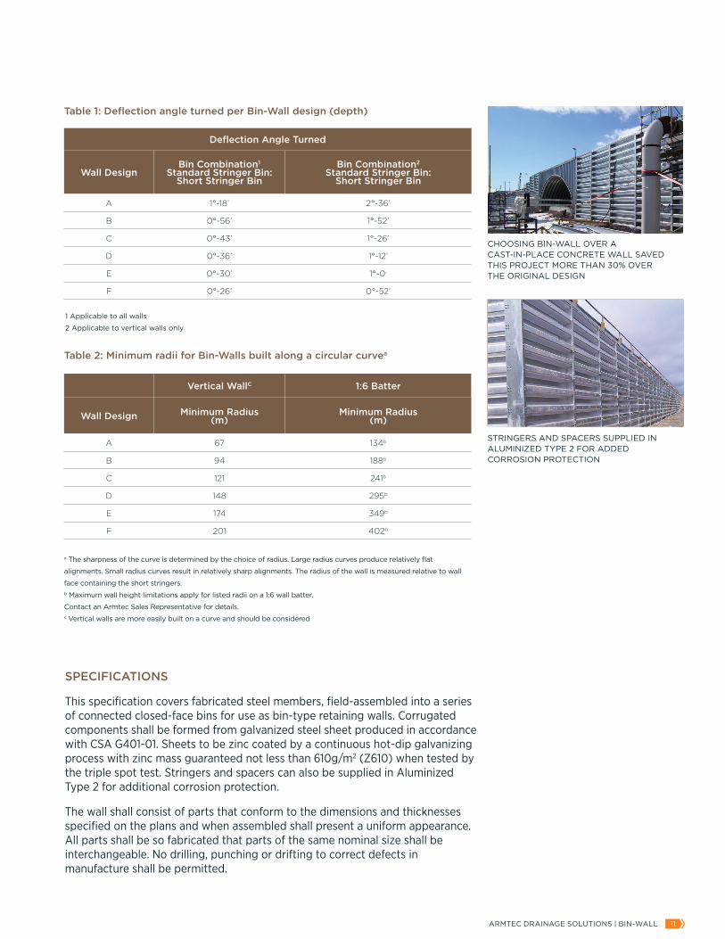
Bin-Walls constructed along a curve follow an arc with a known radius as shown in Figures 3A and 3B. A concave or convex wall curvature is achieved by replacing standard stringers in either the front or rear wall of the bin respectively with short stringers. Varying the ratio of bins containing short stringers to the number of bins with standard length stringers along the length of the arc determines the radius of the curve. Table 1 lists the deflection angle turned for the six Bin-Wall design depths whenever short stringers are located in the front or rear wall face. The minimum radii of curvatures available are also dependent upon the Bin-Wall design depths and wall batter as listed in Table 2. The largest bin depth determines the governing minimum radius for wall layouts containing multiple design depths. Vertical walls are more easily built along a curved alignment and should be considered.
Figure 3B: Convex Bin-Wall on curves
Figure 3A: Concave Bin-Wall on curves
REAR FACE
REAR FACE
FRONT FACE
FRONT FACE
RADIUS
RADIUS
SHORT STRINGERS
SHORT STRINGERS
STANDARDBIN
STANDARDBIN
STANDARDBIN
STANDARDBIN
REAR FACE
REAR FACE
FRONT FACE
FRONT FACE
RADIUS
RADIUS
SHORT STRINGERS
SHORT STRINGERS
STANDARDBIN
STANDARDBIN
STANDARDBIN
STANDARDBIN
Figure 3C: Corner detail of Bin-Wall cover plate
DESIGN AND BUILDING OF BIN-WALLS ON CURVES AND BENDS
Bends and Corners
Distinct changes to the wall alignment require installing custom cover plates on the front face of the bin wherever the bend or corner is located as shown in Figure 3C. The deflection angle between the diverging alignments can vary up to 90 degrees. Cover plates are typically reinforced with structural members located on the soil side of the plate to maintain a flat surface on the visible wall face.
ARMTEC DRAINAGE SOLUTIONS | BIN-WALL 11
Table 2: Minimum radii for Bin-Walls built along a circular curvea
SPECIFICATIONS
This specification covers fabricated steel members, field-assembled into a series of connected closed-face bins for use as bin-type retaining walls. Corrugated components shall be formed from galvanized steel sheet produced in accordance with CSA G401-01. Sheets to be zinc coated by a continuous hot-dip galvanizing process with zinc mass guaranteed not less than 610g/m2 (Z610) when tested by the triple spot test. Stringers and spacers can also be supplied in Aluminized Type 2 for additional corrosion protection.
The wall shall consist of parts that conform to the dimensions and thicknesses specified on the plans and when assembled shall present a uniform appearance. All parts shall be so fabricated that parts of the same nominal size shall be interchangeable. No drilling, punching or drifting to correct defects in manufacture shall be permitted.
Table 1: Deflection angle turned per Bin-Wall design (depth)
Deflection Angle Turned
Wall DesignBin Combination1
Standard Stringer Bin: Short Stringer Bin
Bin Combination2
Standard Stringer Bin: Short Stringer Bin
A 1°-18’ 2°-36’
B 0°-56’ 1°-52’
C 0°-43’ 1°-26’
D 0°-36’ 1°-12’
E 0°-30’ 1°-0’
F 0°-26’ 0°-52’
Vertical WallC 1:6 Batter
Wall Design Minimum Radius(m)
Minimum Radius(m)
A 67 134b
B 94 188b
C 121 241b
D 148 295b
E 174 349b
F 201 402b
1 Applicable to all walls
2 Applicable to vertical walls only
a The sharpness of the curve is determined by the choice of radius. Large radius curves produce relatively flat
alignments. Small radius curves result in relatively sharp alignments. The radius of the wall is measured relative to wall
face containing the short stringers.b Maximum wall height limitations apply for listed radii on a 1:6 wall batter.
Contact an Armtec Sales Representative for details.c Vertical walls are more easily built on a curve and should be considered
CHOOSING BIN-WALL OVER A CAST-IN-PLACE CONCRETE WALL SAVED THIS PROJECT MORE THAN 30% OVER THE ORIGINAL DESIGN
STRINGERS AND SPACERS SUPPLIED IN ALUMINIZED TYPE 2 FOR ADDED CORROSION PROTECTION
12 VISIT ARMTEC.COM FOR MORE INFORMATION
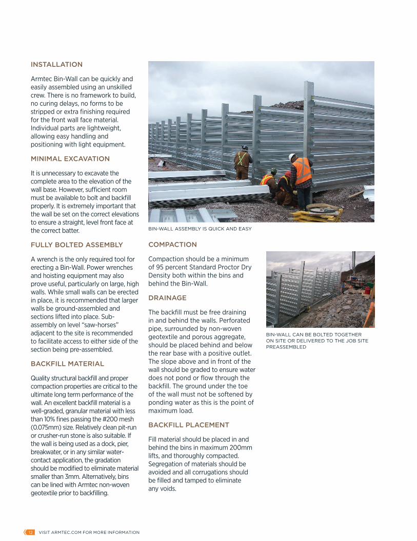
INSTALLATION
Armtec Bin-Wall can be quickly and easily assembled using an unskilled crew. There is no framework to build, no curing delays, no forms to be stripped or extra finishing required for the front wall face material. Individual parts are lightweight, allowing easy handling and positioning with light equipment.
MINIMAL EXCAVATION
It is unnecessary to excavate the complete area to the elevation of the wall base. However, sufficient room must be available to bolt and backfill properly. It is extremely important that the wall be set on the correct elevations to ensure a straight, level front face at the correct batter.
FULLY BOLTED ASSEMBLY
A wrench is the only required tool for erecting a Bin-Wall. Power wrenches and hoisting equipment may also prove useful, particularly on large, high walls. While small walls can be erected in place, it is recommended that larger walls be ground-assembled and sections lifted into place. Sub-assembly on level “saw-horses” adjacent to the site is recommended to facilitate access to either side of the section being pre-assembled.
BACKFILL MATERIAL
Quality structural backfill and proper compaction properties are critical to the ultimate long term performance of the wall. An excellent backfill material is a well-graded, granular material with less than 10% fines passing the #200 mesh (0.075mm) size. Relatively clean pit-run or crusher-run stone is also suitable. If the wall is being used as a dock, pier, breakwater, or in any similar water-contact application, the gradation should be modified to eliminate material smaller than 3mm. Alternatively, bins can be lined with Armtec non-woven geotextile prior to backfilling.
COMPACTION
Compaction should be a minimum of 95 percent Standard Proctor Dry Density both within the bins and behind the Bin-Wall.
DRAINAGE
The backfill must be free draining in and behind the walls. Perforated pipe, surrounded by non-woven geotextile and porous aggregate, should be placed behind and below the rear base with a positive outlet. The slope above and in front of the wall should be graded to ensure water does not pond or flow through the backfill. The ground under the toe of the wall must not be softened by ponding water as this is the point of maximum load.
BACKFILL PLACEMENT
Fill material should be placed in and behind the bins in maximum 200mm lifts, and thoroughly compacted. Segregation of materials should be avoided and all corrugations should be filled and tamped to eliminate any voids.
BIN-WALL ASSEMBLY IS QUICK AND EASY
BIN-WALL CAN BE BOLTED TOGETHER ON SITE OR DELIVERED TO THE JOB SITE PREASSEMBLED
ARMTEC DRAINAGE SOLUTIONS | BIN-WALL 13
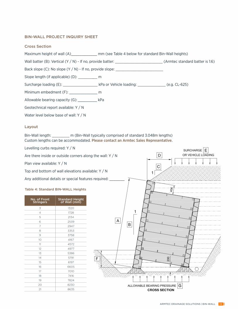
BIN-WALL PROJECT INQUIRY SHEET
Table 4: Standard BIN-WALL Heights
Cross Section
Maximum height of wall (A)____________ mm (see Table 4 below for standard Bin-Wall heights)
Wall batter (B): Vertical (Y / N) - If no, provide batter: ______________________ (Armtec standard batter is 1:6)
Back slope (C): No slope (Y / N) - If no, provide slope: ______________________
Slope length (if applicable) (D): _________ m
Surcharge loading (E): ________________ kPa or Vehicle loading: _____________ (e.g. CL-625)
Minimum embedment (F): _____________ m
Allowable bearing capacity (G): _________ kPa
Geotechnical report available: Y / N
Water level below base of wall: Y / N
Layout
Bin-Wall length: ________ m (Bin-Wall typically comprised of standard 3.048m lengths) Custom lengths can be accommodated. Please contact an Armtec Sales Representative.
Levelling curbs required: Y / N
Are there inside or outside corners along the wall: Y / N
Plan view available: Y / N
Top and bottom of wall elevations available: Y / N
Any additional details or special features required: _______
No. of Front Stringers
Standard Height of Wall (mm)
3 1320
4 1728
5 2134
6 2539
7 2947
8 3353
9 3758
10 4167
11 4572
12 4977
13 5386
14 5791
15 6197
16 6605
17 7010
18 7416
19 7824
20 8230
21 8635
14 VISIT ARMTEC.COM FOR MORE INFORMATION

–Armtec is a leading Canadian infrastructure and construction materials company combining creative engineered solutions, relevant advice, dedicated people, proven products and a national presence with a local focus on exceptional customer service.
1-877-5-ARMTEC | ARMTEC.COM
–Drawings and product details are for information and/or illustrative purposes only, and may vary. Please contact your local Armtec representative for the most current product information.–BIN-WALL/ PRODUCT OVERVIEW | 2016-06PROD-Bin_Wall-PG-2016-6-29-E