bim based on-site surveying - julkaisut - liikennevirasto · · 2015-09-15research reports of the...
TRANSCRIPT
RESEARCH REPORTS OF THE FINNISH TRANSPORT AGENCY
45 • 2015
BIM based on-site surveyingUTILIZATION OF INFRAMODEL3-MODELS IN ON-SITE SURVEYING
RAHUL AHORA


Rahul Arora
BIM based on-site surveying Utilization of InfraModel3-models in
on-site surveying
Research reports of the Finnish Transport Agency 45/2015
Finnish Trasport Agency
Helsinki 2015
Photo on the cover: Android architecture
On-line publication (pdf) (www.liikennevirasto.fi)ISSN-L 1798-6656 ISSN 1798-6664 ISBN 978-952-317-131-2
Finnish Transport Agency P.O.Box 33 00521 HELSINKI, Finland Tel. +358 (0)295 34 3000
3
Rahul Arora: BIM based on-site surveying: Utilization of InfraModel3-models in on-site surveying Finnish Transport Agency, Project Management. Helsinki 2015. Research reports of the Finnish Transport Agency 45/2015. 58 pages and 1 appendix. ISSN-L 1798-6656, ISSN 1798-6664, ISBN 978-952-317-131-2. Keywords: Infrastructre construction, land surveying, android application, Building Information Modeling
Summary
The usage of powerful information technologies has increased in the infrastructure construction field. In the past few years some companies have provided a number of software solutions, which has facilitated the construction process. Land surveying is one such process and this work focuses on revolutionizing it through an Android application. In this thesis a tool is proposed which has the ability to replace the traditional land surveying methods for checking height of the surface layers of a road or railway track by utilization of BIM (Building Information Modeling) models. There were three important considerations to be kept in mind when developing this application. Firstly, the application should be simple enough to be used by anyone on the work site. Secondly, the results provided by the application should be displayed fast enough. Thirdly, the application should fully utilize the potential of the external GPS (global positioning satellite) receiver and provide the maximum possible accuracy of the rover. This work also presents the results of interviews conducted with project managers/ engineers at different organizations in Finland and Sweden. The interviews were conducted to find out the participants’ views on the Android application, various challenges faced by them, skill levels in some construction field related technologies and tools used during work. The above said areas were explored as the aim of the thesis was not only to develop a software solution but also to explore all the factors affecting the usage of software tools in construction companies.

4
Rahul Arora: Rakennuskohteen mittaus tietomallintamisen avulla (BIM): InfraModel3-mallien käyttö rakennuspaikan mittauksissa. Liikennevirasto, hankehallintaosasto. Helsinki 2015. Liikenneviraston tutkimuksia ja selvityksiä 45/2015. 58 sivua ja 1 liite. ISSN-L 1798-6656, ISSN 1798-6664, ISBN 978-952-317-131-2. Avainsanat: infrarakentaminen, maanmittaus, Android-sovellus, rakentamisen tietomallinta-minen (BIM)
Tiivistelmä
Tehokkaan tietotekniikan käyttö on lisääntynyt infrarakentamisessa. Tarjolla on jo muutaman vuoden ajan ollut rakentamista helpottavia ohjelmistosovelluksia. Tässä tutkimuksessa pyritään Android-sovelluksen avulla uudistamaan maanmittaus-prosessi esittelemällä työkalu, jonka avulla perinteiset teiden ja raiteiden pinnan kor-keusmittaukset voidaan korvata käyttämällä tietomallinnusta (BIM, Building Informa-tion Modeling). Tämän sovelluksen kehittämisessä oli huomioitava kolme tärkeää seikkaa. Ensinnäkin, että sovellus olisi helppokäyttöinen, jotta kuka tahansa työmaal-la työskentelevä pystyisi käyttämään sitä. Toiseksi, että tulos olisi tarpeeksi nopeasti saatavilla. Kolmanneksi, että sovellus pystyisi hyödyntämään ulkoisen GPS-vastaan-ottimen (global positioning satellite) koko potentiaalia ja tarjoamaan mahdollisim-man suurta tarkkuutta. Tässä tutkimuksessa esitellään myös eri yhteisöjen suomalaisten ja ruotsalaisten projektinjohtajien/insinöörien haastattelujen tulokset. Haastattelujen avulla pyrittiin selvittämään osallistujien käsityksiä Android-sovelluksesta, minkälaisia haasteita oli esiintynyt sekä tekniikan ja työvälineiden käyttöä ja siihen liittyvää osaamistasoa joil-lakin rakentamisen osa-alueilla. Näitä asioita tutkittiin, koska tutkimuksen tarkoituk-sena ei ainoastaan ollut ohjelmistosovelluksen kehittäminen, vaan pyrittiin myös sel-vittämään, mitkä tekijät vaikuttavat sovellustyökalujen käyttöön rakennusyhtiöissä.
5
Rahul Arora: Byggplatsmätning med hjälp av byggnadsinformationsmodellering (BIM). An-vändning av InfraModel3-modeller vid byggplatsmätningar. Trafikverket, projekthantering. Helsingfors 2015. Trafikverkets undersökningar och utredningar 45/2015. 58 sidor och 1 bilaga. ISSN-L 1798-6656, ISSN 1798-6664, ISBN 978-952-317-131-2. Nyckelord: Infrastrukturbyggnad, lantmäteri, Android-applikation, byggnadsinformations-modellering (BIM)
Sammandrag
Användningen av effektiv informationsteknologi har ökat inom infrastrukturbyggnad. Sedan några år tillbaka har det funnits ett antal programvarulösningar på marknaden som gjort byggnadsprocessen smidigare. Lantmäteri utgör ett exempel på en sådan process som man i den här studien vill revolutionera med hjälp av en Android-applikation. I avhandlingen presenteras ett verktyg som kunde ersätta de traditionella lantmäterimetoderna för att kontrollera höjden på vägars eller järnvägars ytskikt, d.v.s. BIM, byggnadsinformationsmodellering (Building Information Modeling). Följande tre viktiga faktorer beaktades då man utvecklade applikationen: att applikationen skulle vara tillräckligt enkel för att kunna användas av vem som helst på byggarbetsplatsen, att mätresultatet skulle visas tillräckligt snabbt och att applikationen skulle utnyttja den externa GPS-mottagarens (Global Positioning Satellite) hela potential och erbjuda så stor precision som möjligt. I denna avhandling presenteras också resultaten av intervjuerna som gjordes med projektledare/ingenjörer vid olika organisationer i Finland och i Sverige. Intervjuerna gjordes för att få reda på deltagarnas åsikter om Android-applikationen, vilka utmaningar de stött på, de tekniska färdigheterna och verktygen som används under arbetet inom byggnadssektorns olika delområden. De ovan nämnda områdena studerades eftersom avsikten med denna avhandling inte bara var att utveckla en ny programvara, utan också att ta reda på vilka faktorer som påverkar användningen av applikationerna i byggföretagen.
6
Foreword
During recent years, information technology has played an increasing role in project construction processes. Optimum usage of information technology has improved the work processes in construction projects. Purpose of this work is to study possibilities ow on site measurement can be done in near future for client purposes. This theses has been made by Mr. Rahul Arora at the School of Information Sciences (SIS), University of Tampere. The theses is funded by the Finnish Transport Agency. Mr. Teemu Kivimäki, CEO of Infrakit Oy, has supervised the work. The academic supervisor has been Professor Mika Grundström, Dean, School of Information Sciences (SIS), University of Tampere. The work was conducted under the guidance of Ms. Tiina Perttula, BIM Development Manager at the Finnish Transport Agency and Mr. Pasi Nurminen, R&D Manager, Destia Oy. Helsinki August 2015 Finnish Transport Agency Project Management
7
Table of Contents 1 INTRODUCTION ............................................................................................................. 8 1.1 Purpose ............................................................................................................................. 9 1.2 Scope ................................................................................................................................ 9
2 BACKGROUND .............................................................................................................. 10 2.1 Building Information Management ........................................................................... 10
2.1.1 BIM initiatives and international standards ............................................... 12 2.1.2 Uses of BIM ...................................................................................................... 13 2.1.3 Adoption of BIM .............................................................................................. 14 2.1.4 BIM in infrastructure construction industry ............................................... 14 2.1.5 Brief description of BIM solutions offered ................................................. 16
2.2 Land surveying .............................................................................................................. 18 2.2.1 Types of land surveying ................................................................................. 18 2.2.2 Surveying methods ......................................................................................... 18 2.2.3 GPS-based surveying .................................................................................... 20
2.3 LandXML ......................................................................................................................... 22 2.4 Android ........................................................................................................................... 23
2.4.1 History ............................................................................................................... 24 2.4.2 Android architecture ....................................................................................... 24 2.4.3 Android for developers .................................................................................. 26 2.4.4 Native Android development ....................................................................... 26
2.5 Architecture .................................................................................................................. 26 2.5.1 Application architecture ............................................................................... 26 2.5.2 System Architecture ...................................................................................... 28
2.6 Application as a part of Internet of Things environment ..................................... 30
3 METHODS AND DEVELOPMENT PROCESS ............................................................ 31 3.1 Developing the application ......................................................................................... 31 3.2 Application interface and components .................................................................... 32
3.2.1 Application interface design principles ...................................................... 32 3.2.2 Components of the application ................................................................... 33
3.3 Main uses of the application ..................................................................................... 34 3.4 Interviews ....................................................................................................................... 37
4 RESULTS ....................................................................................................................... 39 4.1 Skill level in related technologies ............................................................................ 39 4.2 Challenges faced in communication ......................................................................... 41 4.3 Tools used on the site during work ........................................................................... 42 4.4 Information most interesting to participants.......................................................... 42 4.5 Views on the Android application ............................................................................. 43
5 TESTING AND IMPLEMENTATION OF THE APPLICATION ................................ 44 5.1 Implementation ........................................................................................................... 44 5.2 Testing ........................................................................................................................... 46
6 DISCUSSION, CONCLUSION AND FUTURE WORK ............................................. 48 6.1 Analysis of interview results ...................................................................................... 48 6.2 Conclusion .................................................................................................................... 49 6.3 Future work .................................................................................................................... 51
REFERENCES............................................................................................................................. 53
APPENDICES Appendix 1 Questionnaire
8
1 Introduction
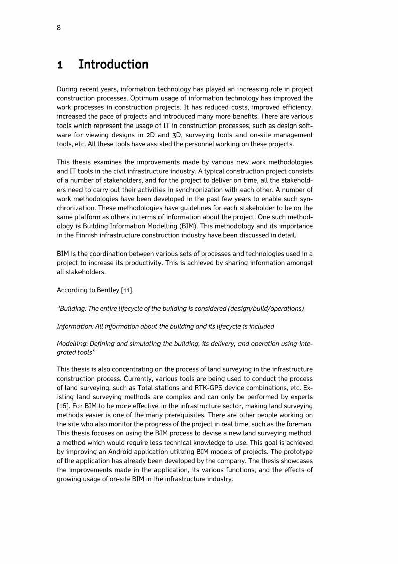
During recent years, information technology has played an increasing role in project construction processes. Optimum usage of information technology has improved the work processes in construction projects. It has reduced costs, improved efficiency, increased the pace of projects and introduced many more benefits. There are various tools which represent the usage of IT in construction processes, such as design soft-ware for viewing designs in 2D and 3D, surveying tools and on-site management tools, etc. All these tools have assisted the personnel working on these projects. This thesis examines the improvements made by various new work methodologies and IT tools in the civil infrastructure industry. A typical construction project consists of a number of stakeholders, and for the project to deliver on time, all the stakehold-ers need to carry out their activities in synchronization with each other. A number of work methodologies have been developed in the past few years to enable such syn-chronization. These methodologies have guidelines for each stakeholder to be on the same platform as others in terms of information about the project. One such method-ology is Building Information Modelling (BIM). This methodology and its importance in the Finnish infrastructure construction industry have been discussed in detail. BIM is the coordination between various sets of processes and technologies used in a project to increase its productivity. This is achieved by sharing information amongst all stakeholders. According to Bentley [11], “Building: The entire lifecycle of the building is considered (design/build/operations) Information: All information about the building and its lifecycle is included Modelling: Defining and simulating the building, its delivery, and operation using inte-grated tools” This thesis is also concentrating on the process of land surveying in the infrastructure construction process. Currently, various tools are being used to conduct the process of land surveying, such as Total stations and RTK-GPS device combinations, etc. Ex-isting land surveying methods are complex and can only be performed by experts [16]. For BIM to be more effective in the infrastructure sector, making land surveying methods easier is one of the many prerequisites. There are other people working on the site who also monitor the progress of the project in real time, such as the foreman. This thesis focuses on using the BIM process to devise a new land surveying method, a method which would require less technical knowledge to use. This goal is achieved by improving an Android application utilizing BIM models of projects. The prototype of the application has already been developed by the company. The thesis showcases the improvements made in the application, its various functions, and the effects of growing usage of on-site BIM in the infrastructure industry.

9
The proposed tool will help people working on the site carry out the survey of the area in question and check if the construction has been done in accordance with the plan. Emphasis has been given to improving a work process which uses an Android tablet and an RTK-GPS device in the work field, integrated with Infrakit’s construction solu-tions at the backend. The proposed system simplifies the collection of as-built points and combines them with InfraModel3 design files to provide an as-built model. It ap-pears that a lot can be done in this field, and thus the research will explore new as-pects, aiming at bringing a significant change in how land surveying and reviewing are carried out in construction projects. During the course of the thesis work, I have also had the opportunity to interview pro-ject managers from a variety of organizations. The qualitative research throws light on the current usage of tools in the Finnish organizations as well as knowledge con-cerning the BIM, together with various other issues.
1.1 Purpose
This work attempts to answer the following questions:
How does having access to updated/accurate designs in real time affect the work of supervisors/project managers?
How do the possibilities of making accurate measurements and comparing them to designs in real time help in day-to-day work completed in the field by supervisors?
How does saving ‘as-built’ quality measurements help supervisors/project managers?
1.2 Scope
Researching the BIM and land surveying techniques was the most time-consuming element of the thesis. The implementation of the suggested improvements also con-sumed a considerable amount of time. They were rather difficult to implement due to the background information needed to develop the application. The ideas on which the application can be developed further in the future are also listed in this document. These concepts and ideas were collected by interviewing project managers from a number of construction companies in Finland and Sweden. This thesis is divided into six chapters. Chapter 2 describes the BIM, land surveying, LandXML. Chapter 3 describes the method used for interviewing the project managers and developmental process of the application, and Chapter 4 concentrates on show-casing the results of the interviews. Chapter 5 describes the testing of the application and implementation of the new features in application. Chapter 6 presents discussion of the results, summarizes the work, and presents some of the future research oppor-tunities in the field of onsite BIM usage.
10
2 Background
This chapter covers the background information of the technologies utilized during the project. The understanding of these technologies is important towards under-standing the overall concept of this thesis. The basics of Building Information Model-ling (BIM), InfraModel 3, land surveying basics, Android platform and application ar-chitecture.
2.1 Building Information Management
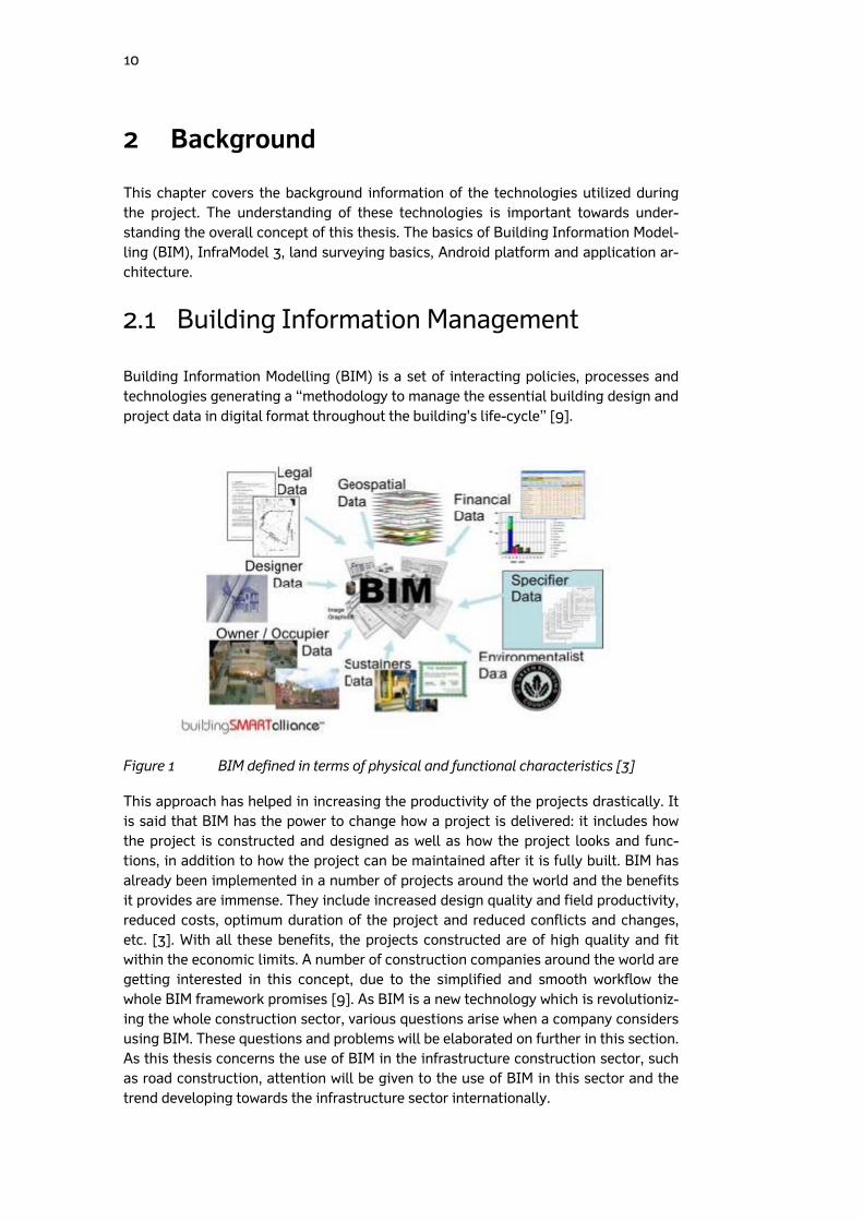
Building Information Modelling (BIM) is a set of interacting policies, processes and technologies generating a “methodology to manage the essential building design and project data in digital format throughout the building's life-cycle” [9].
Figure 1 BIM defined in terms of physical and functional characteristics [3]
This approach has helped in increasing the productivity of the projects drastically. It is said that BIM has the power to change how a project is delivered: it includes how the project is constructed and designed as well as how the project looks and func-tions, in addition to how the project can be maintained after it is fully built. BIM has already been implemented in a number of projects around the world and the benefits it provides are immense. They include increased design quality and field productivity, reduced costs, optimum duration of the project and reduced conflicts and changes, etc. [3]. With all these benefits, the projects constructed are of high quality and fit within the economic limits. A number of construction companies around the world are getting interested in this concept, due to the simplified and smooth workflow the whole BIM framework promises [9]. As BIM is a new technology which is revolutioniz-ing the whole construction sector, various questions arise when a company considers using BIM. These questions and problems will be elaborated on further in this section. As this thesis concerns the use of BIM in the infrastructure construction sector, such as road construction, attention will be given to the use of BIM in this sector and the trend developing towards the infrastructure sector internationally.
11
Until the middle of the 19th century, engineers all over the world were using simple tools to model the designs of the building they were about to construct. Due to the advances in mathematics and computer engineering, things slowly started to change. 2D CAD was a breakthrough innovation in this sector. 2D developed into 3D, and this changed the way buildings were visualized, which also altered the relationship be-tween structural engineering and architectural engineering. 3D CAD is a collection of points, lines, 2D shapes and volumes, etc., whereas BIM is even beyond 3D CAD, as it has all the functions of 3D CAD: in addition, all geometric entities can also be repre-sented with symbolic meanings as well as qualitative or quantitative data [10]. The BIM project execution planning guide (2009) described BIM as a process – the process of Building Information Modelling. It has been described as “a process fo-cussed on the development, use and transfer of a digital information model of a build-ing project to improve the design, construction and operations of a project or a portfolio of facilities” According to Succar, BIM includes not only the software which allows for information input and 3D modelling but also project management tools and processes. He be-lieves that consideration for the holistic nature of BIM should make it a very useful tool for project managers. BIM will help them maintain a positive collaboration with all project stakeholders. This improved synchronization between the stakeholders will reap benefits for the project. The trust and cooperation between the various partners in the project is essential for its success, and BIM could be the key approach to en-sure this success [1]. There have been various academic studies and researches on the usage of BIM in the construction industry, with very few listing it as a project management tool. Allison (2010) mentioned BIM as a tool which can be used for project management, and de-scribes how a project manager can unleash its true potential by using 5D BIM. The two extra dimensions, in addition to 3D, represent the concepts of scheduling infor-mation and information extraction with the intent of estimating the project by the model itself. This additional advantage of BIM is one of the many reasons prompting the infrastructure construction industry to use BIM in road and rail construction pro-jects. Some sources consider BIM to be scalable to any number of additional dimen-sions [2]. To qualify as BIM, a model needs to fulfil two major conditions: it must be a 3D-based object representation and has to retain the information and properties of the object. BIM is beyond 3D modelling; it is not just a collection of points, designs and shapes. In BIM, all these entities carry an abstract meaning, as they are part of a bigger meth-odology and not the system itself [10]. Out of the many suggested frameworks on which BIM may function, one has been described below. The framework is divided into technology, process and policy components with two subfields – namely, players and deliverables. BIM technology field: This is a combination of various software, hardware, equipment and networking systems which play an important role in BIM. It also includes the software companies which provide software solutions and applications. This is where the research will be basically focused on, due to the involvement of an Android appli-cation in the final solution which this research tends to generate [1].

12
BIM process field: This includes the specific ordering of work activities across time and place, with a beginning, an end, and clearly identified inputs and outputs. There are a number of players which are part of the process fields, such as engineers, archi-tectures and the foreman, etc., who produce, manage, construct and manufacture [18]. BIM policy field: Policy includes group or rules or documentation which can guide decision-making. There are also players involved in this field, but they are not respon-sible for manufacturing; instead, they are specialized organizations – such as insur-ance companies, regulatory authorities and research centres, etc. They play an im-portant role in regulating the whole process [1]. BIM fields also share deliverables. This is called field overlap and happens when something which must be delivered requires players from two fields: for example, the development of IFCs requires the knowledge of both software developers and policy makers. This part addresses the detailed background information about Building Information Modelling and its usage. 2.1.1 BIM initiatives and international standards
There are various international organizations which promote and support the usage of BIM. One of the biggest ones is buildingSMART International (bsI). According to its website [13]: “buildingSMART is the worldwide authority driving the transformation of the built envi-ronment through creation & adoption of open, international standards” The organization is supported by leading software, construction-related instruments developers and construction companies. BuildingSMART International has developed a common schema that helps in sharing and holding data from one software applica-tion to another [3]. The bSI model standard is defined by Industry Foundation Classes (IFCs). According to bSI: “‘Open’ is the key to the real value of our buildingSMART standard. IFC can be used toexchange and share BIM data between applications developed by different software vendors without the software having to support numerous native formats. As an open format, IFCdoes not belong to a single software vendor; it is neutral and independent of a particular vendor’s plans for software development. For this reason, we say that our organisation – buildingSMART – is ‘the home of open BIM’.” The strategic advisory council of the organization has four members: Autodesk, Trim-ble, HOK and Nemetschek [13]. The organization also has its chapters in various parts of the world. Finland also has a bSI chapter named buildingSMART Finland. It is sup-ported by some of the Finnish construction companies, software vendors and A/E consultants [14].
13
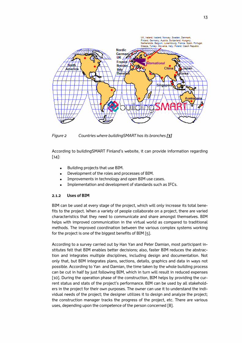
Figure 2 Countries where buildingSMART has its branches [3]
According to buildingSMART Finland’s website, it can provide information regarding [14]:
Building projects that use BIM. Development of the roles and processes of BIM. Improvements in technology and open BIM use cases. Implementation and development of standards such as IFCs.
2.1.2 Uses of BIM
BIM can be used at every stage of the project, which will only increase its total bene-fits to the project. When a variety of people collaborate on a project, there are varied characteristics that they need to communicate and share amongst themselves. BIM helps with improved communication in the virtual world as compared to traditional methods. The improved coordination between the various complex systems working for the project is one of the biggest benefits of BIM [5]. According to a survey carried out by Han Yan and Peter Damian, most participant in-stitutes felt that BIM enables better decisions; also, faster BIM reduces the abstrac-tion and integrates multiple disciplines, including design and documentation. Not only that, but BIM integrates plans, sections, details, graphics and data in ways not possible. According to Yan and Damian, the time taken by the whole building process can be cut in half by just following BIM, which in turn will result in reduced expenses [10]. During the operation phase of the construction, BIM helps by providing the cur-rent status and stats of the project’s performance. BIM can be used by all stakehold-ers in the project for their own purposes. The owner can use it to understand the indi-vidual needs of the project; the designer utilizes it to design and analyze the project; the construction manager tracks the progress of the project, etc. There are various uses, depending upon the competence of the person concerned [8].
14
In recent times, BIM has been used in high-profile buildings as well. These include London 2012 Olympic cycling Velodrome, the Shanghai Tower, Hong Kong Interna-tional Airport, the Cathay Pacific cargo terminal, the Walt Disney Concert Hall, Heathrow’s Terminal 5 and so on [2]. 2.1.3 Adoption of BIM
The adoption of the BIM has been a considerable challenge for its supporters. Com-panies are not very open to adopt it as their sole working methodology. The reason stated by most of the organizations is that they are obliged to invest considerable time and money in training their employees to use BIM [10]. Various countries in the world are trying to shift companies’ opinions in favour of BIM. The Institute for BIM in Canada took a survey to find out the factors behind non-compliance to BIM. One of the main causes was a lack of recognition by public clients [4]. In 2010, buildingSMART Australia conducted a research effort to investigate negligi-ble usage of BIM. The answers were more related to the technological improvement of BIM implementation, and this can be related to the changes in organization and busi-ness processes [4]. According to McGraw-Hill Construction, the industry-wide adoption of BIM in North America has increased from 28% in 2007 to 49% in 2009, and to 71% in 2012 [55]. In 2014, The European Union recommended that all 28 member states employ BIM in construction projects in order to save costs and deliver the projects on time. The ac-tual usage by each country has to be observed over the passage of time [41]. In the same year, the UK government made strong recommendations to the companies to use 3D BIM in order to secure governmental contracts, better known as public-funded projects. According to the government, it has saved 2 billion euros since 2012 due to the use of BIM in such projects. Out of these, 66% were delivered within budget and time [6]. This is regarded as a positive step in BIM usage. A similar decision has been taken by such countries as Norway, the Netherlands, Denmark and Finland [41]. In Finland, the Traffic Agency of Finland has recommended that construction companies use BIM for infrastructure construction projects from May, 2014, onwards. This in-cludes guidelines on the full-scale usage of BIM on the project level as well as in sep-arate phases [34]. Countries and organizations are slowly realizing the potential of this technology. 2.1.4 BIM in infrastructure construction industry
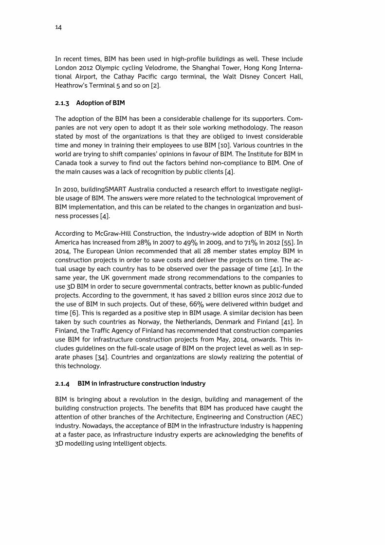
BIM is bringing about a revolution in the design, building and management of the building construction projects. The benefits that BIM has produced have caught the attention of other branches of the Architecture, Engineering and Construction (AEC) industry. Nowadays, the acceptance of BIM in the infrastructure industry is happening at a faster pace, as infrastructure industry experts are acknowledging the benefits of 3D modelling using intelligent objects.
15
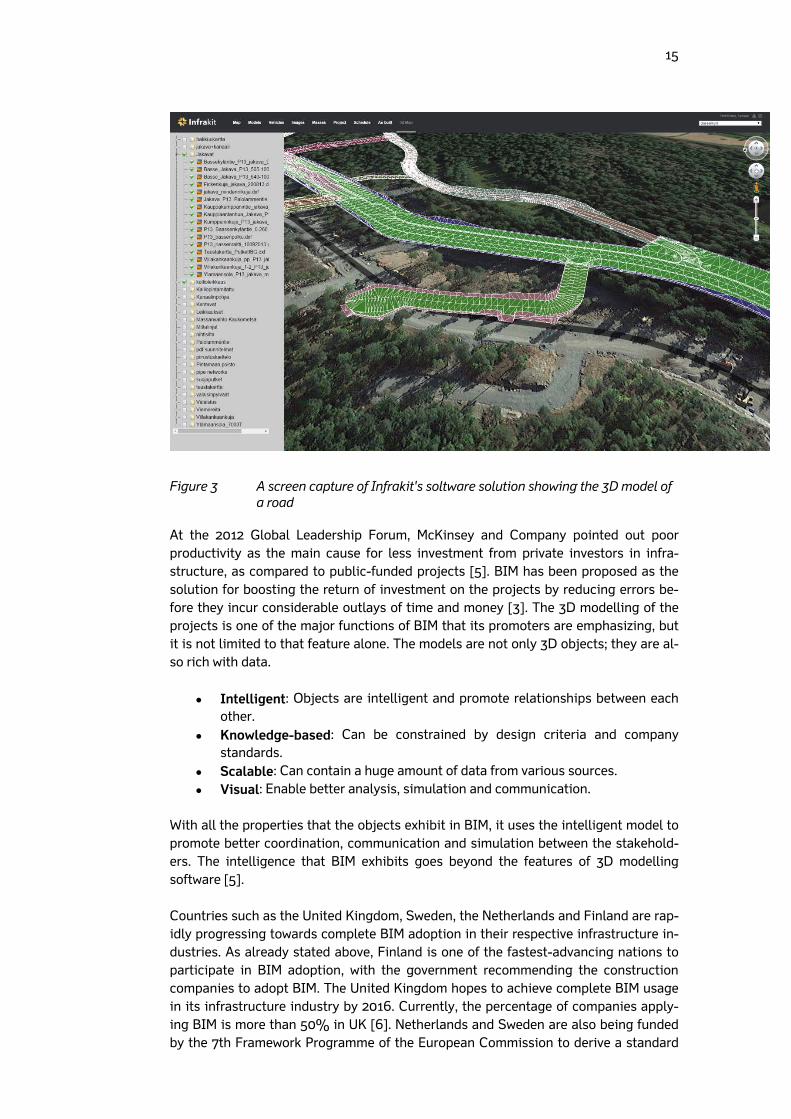
Figure 3 A screen capture of Infrakit's soltware solution showing the 3D model of a road
At the 2012 Global Leadership Forum, McKinsey and Company pointed out poor productivity as the main cause for less investment from private investors in infra-structure, as compared to public-funded projects [5]. BIM has been proposed as the solution for boosting the return of investment on the projects by reducing errors be-fore they incur considerable outlays of time and money [3]. The 3D modelling of the projects is one of the major functions of BIM that its promoters are emphasizing, but it is not limited to that feature alone. The models are not only 3D objects; they are al-so rich with data.
Intelligent: Objects are intelligent and promote relationships between each other.
Knowledge-based: Can be constrained by design criteria and company standards.
Scalable: Can contain a huge amount of data from various sources. Visual: Enable better analysis, simulation and communication.
With all the properties that the objects exhibit in BIM, it uses the intelligent model to promote better coordination, communication and simulation between the stakehold-ers. The intelligence that BIM exhibits goes beyond the features of 3D modelling software [5]. Countries such as the United Kingdom, Sweden, the Netherlands and Finland are rap-idly progressing towards complete BIM adoption in their respective infrastructure in-dustries. As already stated above, Finland is one of the fastest-advancing nations to participate in BIM adoption, with the government recommending the construction companies to adopt BIM. The United Kingdom hopes to achieve complete BIM usage in its infrastructure industry by 2016. Currently, the percentage of companies apply-ing BIM is more than 50% in UK [6]. Netherlands and Sweden are also being funded by the 7th Framework Programme of the European Commission to derive a standard

16
framework to introduce BIM in the field of road construction and road management; this programme has been named V-Con, Virtual Construction for Roads. The project is being led by the Dutch Ministry of Infrastructure and Environment. The other partners in the project are the national Swedish rail and road authority, as well as two leading research institutes in virtual construction from France and the Netherlands. The pro-ject was initiated in 2012 and will continue till 2016 [12]. The activity by the countries in adopting BIM in the infrastructure shows how concerned the countries are about reaping the benefits by adopting BIM as early as possible. 2.1.5 Brief description of BIM solutions offered
A product is more acknowledged in the market if the big players show greater interest in it. The same is happening with BIM as more software vendors and big names in the construction industry are launching products which provide solutions and streamline the usage of BIM. Usage of these solutions makes adoption of BIM easier, overcoming a major challenge. Some of these solutions have been reviewed in this section of the thesis. The first one is Autodesk Revit. As the name suggests, it is produced by the world’s biggest CAD software manufacturer, Autodesk. The Autodesk Revit is de-signed to obtain the maximum benefits out of BIM, and contains the features related to structural engineering, architecture and construction features which make it a much-needed BIM tool. It can display complex terrains and surfaces through the use of its improved cloud manipulation (realized by 3D scanners). It also has a feature which enables it to work with parametric components – bidirectional associativity through the use of viewports, which suggests that “a change anywhere is change eve-rywhere”. Improved design tools even enable it to model free-form shapes. There are various features which can help in improving the visualization of the final model. It also helps in producing detailed cost and material analysis. This software has been actively used in the construction of roads and bridges [6]. Microstation 2D and 3D is the second tool on the list, developed by another heavy-weight in this market, Bentley. This tool showcases its capabilities over a larger area of branches such as architecture, engineering, construction and the operation of utili-ty systems. Graphic design simulation, format interoperability, point clouds to obtain accurate field conditions, geo-coordination, connecting relevant data to a three-dimensional model, and hypermodeling to automate design generation: Microstation is not limited to these functions but also offers animation and simulation of model-like capabilities to boost its position in the BIM solutions market. This tool has been used in building rails, roads, bridges, water networks and communication networks, etc. [6]. Another market leader, Trimble, offers a solution named BIMsight. Launched in 2011, this tool enjoys the acceptance of over 160,000 professionals working in more than 160 countries, thanks to features such as a friendly user interface, good detection of errors, and versatility. The biggest appealing factor is that the software is free to download. It allows adding notes to the model, indicating warnings and errors that can be observed by all those involved in the project. Additionally, it also allows docu-ments, photographs and drawings to be added to the model, linking them to a specific element in the model [6]. Its ability in handling road projects can be demonstrated by the construction of a tunnel 2.8 km long in Seattle [42].

17
Vianova, the Norwegian construction software manufacturer, also offers BIM solu-tions. They are widely used in Norway within many projects. NovapointDCM and QuadriDCM are used in collaboration (DCM stands for design, construction and maintenance). NovapointDCM is responsible for showing the models of the project in 2D and 3D; it also helps in collating different models into a single integrated BIM model. Data from this software can also be used by GML-supporting software. The integrated collaboration of BIM models is achieved by using the QuadriDCM solution, which enables cloud-based sharing among all the disciplines. It allows several de-signers to work on the same model at once, thus enabling better sharing of data be-tween the stakeholders. Topcon Sitelink3D uses BIM through the total management of the worksite. It enables real-time tracking of all excavators working on the site. All the machines can be tracked on laptops or mobile devices. It also includes transfer of files and site-support messaging. It is branded by the company as a complete site communication setup. Another company which has been providing solutions to manage BIM information in infrastructure construction projects is Infrakit. This Finland-based company develops software under the same name, which is a useful tool in managing BIM models during the design, construction and quality control phases. It is easy and straightforward. Infrakit visualizes BIM 3D models on the map and satellite images and validates file conformity. Once BIM designs pass Infrakit validation, they are ready to be visualized on the correct spot on the map. It also offers excavator fleet management, tools for volume calculation and scheduling, and the gathering of ‘as-built’ points and compar-ison to designs. There are many other software solutions empowering the use of BIM in the road, rail and bridge construction industry, as well as in other areas of expertise. Machine control systems: Topcon, Trimble, Scanlaser leica Power Digger, Novatron, Prolec, Digpilot, Carlsson Design software: Novapoint, Bentley Microstation InRoads, Tekla civil, Autocad civil Project portal software: Bentley Projectwise, Vianova vdc, Buildercom, Sokopro, Tekla BIM sight, Infrakit Site management software: Topcon Sitelink, Trimble connected community, Leica iCON Telematics, Infrakit Professional Surveying software/equipment: Geomax Android surveying applica-tion, Topcon, Trimble, Carlson software, Leica Surveying Computer Aided Design and Drafting Software (CADs): 3d Win Light (Finland), Topocad (Sweden), Trimble business centre, Topcon 3d office

18
2.2 Land surveying
Land surveying can be described as the methodology of plotting a position in a three-dimensional space on or beneath the surface of Earth. The position can be shown on a map or in plain form. The map itself can be analogue or digital. Surveying an area on which construction is to be done aids in planning, design and other important phases of the construction [16]. The act of surveying is done after following a series of steps. The first step involves management-level decisions such as which techniques should be used in surveying to complete the task satisfactorily within the specified accuracy range. These decisions can only be taken when the area to be surveyed is properly examined [19]. After choosing the techniques and tools that will be used for surveying, the next step is to carry out the surveying in the field. After this, data processing is performed, typi-cally through the aid of general or field computers. The data gathered from the sur-veying can then be represented either in analogue or in digital form. These are the standard steps followed for surveying in every project – whether it concerns building dams, constructing roads or erecting a new town complex. The survey engineer can only succeed if he is aware of the accuracy limits and possesses the right techniques and instruments; this allows completing the project in an economical manner and within the shortest time [19]. 2.2.1 Types of land surveying
In geodetic surveys, the surface of the Earth is considered to be an ellipsoid when referencing the X and Y dimensions. The Z value is bound to mean sea level [17]. The-se surveys are carried out on a national basis, which provides a framework of survey stations plotted some distance apart from each other. These are conducted with the highest level of accuracy and extended over large areas [15]. In topographic surveys, various physical features of the earth are measured, such as natural and man-made features. Their position relative to each other is showcased on a map. These surveys display the real-world features existing on the ground on the surface of the map [15]. In plane surveying, the shape of the earth is not taken into consideration whilst per-forming the surveying; instead, the surface is assumed to be a plane for all values of X and Y [17]. Engineering/site surveys are performed in construction projects. These can include a topographic or plane survey, depending upon the construction area. They are used in building construction and infrastructure construction, etc. [15]. 2.2.2 Surveying methods
There are a number of techniques used for land surveying in the civil engineering world. Some of the techniques are used more frequently due to several reasons – such as producing fewer errors, taking less time for surveys, for instance. With the intro-duction of new technologies in the civil engineering area in the past decade, new
19
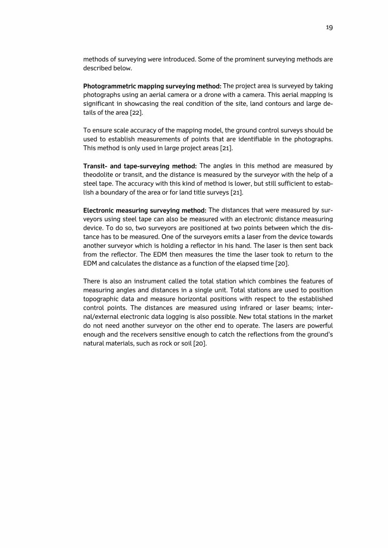
methods of surveying were introduced. Some of the prominent surveying methods are described below. Photogrammetric mapping surveying method: The project area is surveyed by taking photographs using an aerial camera or a drone with a camera. This aerial mapping is significant in showcasing the real condition of the site, land contours and large de-tails of the area [22]. To ensure scale accuracy of the mapping model, the ground control surveys should be used to establish measurements of points that are identifiable in the photographs. This method is only used in large project areas [21]. Transit- and tape-surveying method: The angles in this method are measured by theodolite or transit, and the distance is measured by the surveyor with the help of a steel tape. The accuracy with this kind of method is lower, but still sufficient to estab-lish a boundary of the area or for land title surveys [21]. Electronic measuring surveying method: The distances that were measured by sur-veyors using steel tape can also be measured with an electronic distance measuring device. To do so, two surveyors are positioned at two points between which the dis-tance has to be measured. One of the surveyors emits a laser from the device towards another surveyor which is holding a reflector in his hand. The laser is then sent back from the reflector. The EDM then measures the time the laser took to return to the EDM and calculates the distance as a function of the elapsed time [20]. There is also an instrument called the total station which combines the features of measuring angles and distances in a single unit. Total stations are used to position topographic data and measure horizontal positions with respect to the established control points. The distances are measured using infrared or laser beams; inter-nal/external electronic data logging is also possible. New total stations in the market do not need another surveyor on the other end to operate. The lasers are powerful enough and the receivers sensitive enough to catch the reflections from the ground’s natural materials, such as rock or soil [20].
20
Figure 4 A total station mounted on a tripod [20]
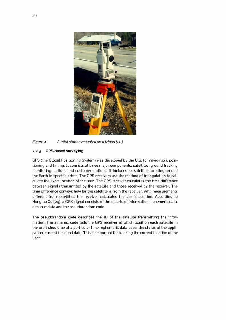
2.2.3 GPS-based surveying
GPS (the Global Positioning System) was developed by the U.S. for navigation, posi-tioning and timing. It consists of three major components: satellites, ground tracking monitoring stations and customer stations. It includes 24 satellites orbiting around the Earth in specific orbits. The GPS receivers use the method of triangulation to cal-culate the exact location of the user. The GPS receiver calculates the time difference between signals transmitted by the satellite and those received by the receiver. The time difference conveys how far the satellite is from the receiver. With measurements different from satellites, the receiver calculates the user’s position. According to Hongtao Xu [24], a GPS signal consists of three parts of information: ephemeris data, almanac data and the pseudorandom code. The pseudorandom code describes the ID of the satellite transmitting the infor-mation. The almanac code tells the GPS receiver at which position each satellite in the orbit should be at a particular time. Ephemeris data cover the status of the appli-cation, current time and date. This is important for tracking the current location of the user.
21
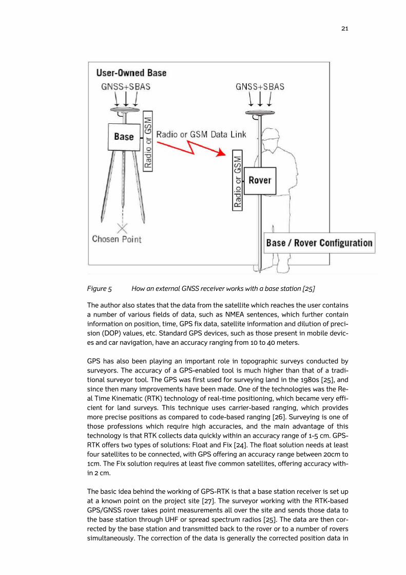
Figure 5 How an external GNSS receiver works with a base station [25]
The author also states that the data from the satellite which reaches the user contains a number of various fields of data, such as NMEA sentences, which further contain information on position, time, GPS fix data, satellite information and dilution of preci-sion (DOP) values, etc. Standard GPS devices, such as those present in mobile devic-es and car navigation, have an accuracy ranging from 10 to 40 meters. GPS has also been playing an important role in topographic surveys conducted by surveyors. The accuracy of a GPS-enabled tool is much higher than that of a tradi-tional surveyor tool. The GPS was first used for surveying land in the 1980s [25], and since then many improvements have been made. One of the technologies was the Re-al Time Kinematic (RTK) technology of real-time positioning, which became very effi-cient for land surveys. This technique uses carrier-based ranging, which provides more precise positions as compared to code-based ranging [26]. Surveying is one of those professions which require high accuracies, and the main advantage of this technology is that RTK collects data quickly within an accuracy range of 1-5 cm. GPS-RTK offers two types of solutions: Float and Fix [24]. The float solution needs at least four satellites to be connected, with GPS offering an accuracy range between 20cm to 1cm. The Fix solution requires at least five common satellites, offering accuracy with-in 2 cm. The basic idea behind the working of GPS-RTK is that a base station receiver is set up at a known point on the project site [27]. The surveyor working with the RTK-based GPS/GNSS rover takes point measurements all over the site and sends those data to the base station through UHF or spread spectrum radios [25]. The data are then cor-rected by the base station and transmitted back to the rover or to a number of rovers simultaneously. The correction of the data is generally the corrected position data in
22
northing, easting and elevation values converted from latitude, longitude and altitude values received from the GPS/GNSS rover. The conversion is done into local coordi-nates, as each country has its own specific local coordinates which describe a known point in that country in meters rather than in degrees. The data collected using the technology can then be transferred into computer software and used in a design file. According to Hangtao Xu [24], the accuracy of the position data depends upon vari-ous factors, such as the strength of the connection between the rover and the base station. The connection is further dependent upon interference from man-made or natural obstacles between the rover and the station. The accuracy also depends upon the satellites that are observable or connected. The information relayed between the base station and rover is not always sent over radio: some high-end rovers have built-in SIM card slots, which enables an Internet connection within rovers.
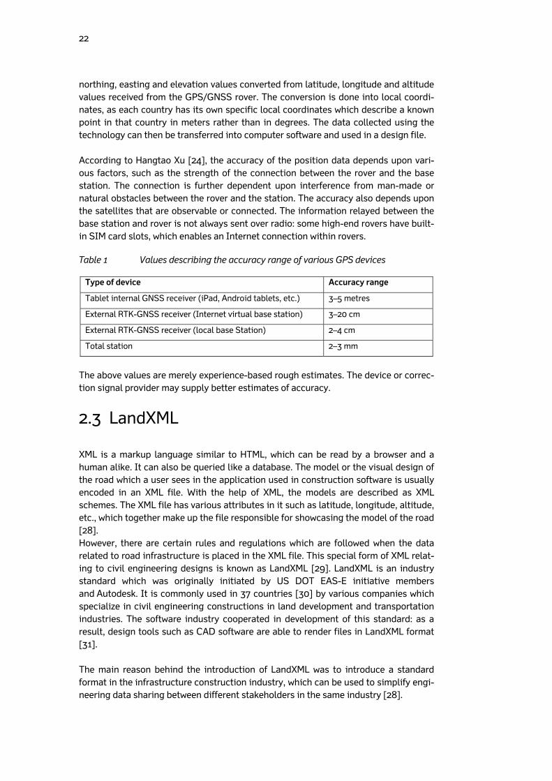
Table 1 Values describing the accuracy range of various GPS devices
Type of device Accuracy range
Tablet internal GNSS receiver (iPad, Android tablets, etc.) 3–5 metres
External RTK-GNSS receiver (Internet virtual base station) 3–20 cm
External RTK-GNSS receiver (local base Station) 2–4 cm
Total station 2–3 mm
The above values are merely experience-based rough estimates. The device or correc-tion signal provider may supply better estimates of accuracy.
2.3 LandXML
XML is a markup language similar to HTML, which can be read by a browser and a human alike. It can also be queried like a database. The model or the visual design of the road which a user sees in the application used in construction software is usually encoded in an XML file. With the help of XML, the models are described as XML schemes. The XML file has various attributes in it such as latitude, longitude, altitude, etc., which together make up the file responsible for showcasing the model of the road [28]. However, there are certain rules and regulations which are followed when the data related to road infrastructure is placed in the XML file. This special form of XML relat-ing to civil engineering designs is known as LandXML [29]. LandXML is an industry standard which was originally initiated by US DOT EAS-E initiative members and Autodesk. It is commonly used in 37 countries [30] by various companies which specialize in civil engineering constructions in land development and transportation industries. The software industry cooperated in development of this standard: as a result, design tools such as CAD software are able to render files in LandXML format [31]. The main reason behind the introduction of LandXML was to introduce a standard format in the infrastructure construction industry, which can be used to simplify engi-neering data sharing between different stakeholders in the same industry [28].
23
The infrastructure construction companies in Finland have been encouraged by the Transport Agency of Finland to use the InfraModel format instead of standard LandXML [32]. According to InfraModel Finland website [33], the InfraModel format is an open data exchange format developed by the Transport Agency of Finland, based on the international standard of LandXML. The latest version of InfraModel, In-fraModel 3, is in use now and is based on LandXML version 1.2. According to the Finn-ish Transport Authority [34], all the projects launched by Transport Agency of Finland after May 1, 2014 require organizations to use this format. The organizations have al-so been provided with general modelling requirements and other guidelines. Guid-ance on the implementation of the standard and the guidelines on the exchange of data and implementation models have been documented. The main motive for the introduction of this format was to provide software-independent data, which can be used by all stakeholders involved in design and implementation of the models. More updates to the current version are being planned, and the continuous development of the format will follow. The format has been created in the InfraFINBIM package of the RYM PRE Program. According to the InfraModel website [33], the InfraModel documentation consists of:
InfraModel XML-schema (LandXML v1.2 schema with specific restrictions, XSD and HTML schema documentation),
Enumerations XML-schema (applicable values for certain data types, XSD), and
InfraModel application documentation (HTML manual for implementation re-strictions and guidance).
2.4 Android
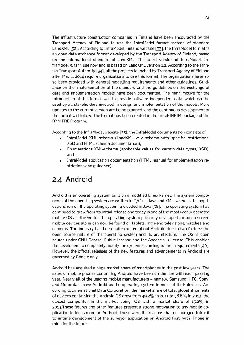
Android is an operating system built on a modified Linux kernel. The system compo-nents of the operating system are written in C/C++, Java and XML, whereas the appli-cations run on the operating system are coded in Java [38]. The operating system has continued to grow from its initial release and today is one of the most widely operated mobile OSs in the world. The operating system primarily developed for touch screen mobile devices alone can now be found on tablets, high-end televisions, watches and cameras. The industry has been quite excited about Android due to two factors: the open source nature of the operating system and its architecture. The OS is open source under GNU General Public License and the Apache 2.0 license. This enables the developers to completely modify the system according to their requirements [40]. However, the official releases of the new features and advancements in Android are governed by Google only. Android has acquired a huge market share of smartphones in the past few years. The sales of mobile phones containing Android have been on the rise with each passing year. Nearly all of the leading mobile manufacturers – namely, Samsung, HTC, Sony, and Motorola – have Android as the operating system in most of their devices. Ac-cording to International Data Corporation, the market share of total global shipments of devices containing the Android OS grew from 49.2% in 2011 to 78.6% in 2013, the closest competitor in the market being iOS with a market share of 15.2% in 2013.These figures and other features present a strong motivation to any mobile ap-plication to focus more on Android. These were the reasons that encouraged Infrakit to initiate development of the surveyor application on Android first, with iPhone in mind for the future.
24
Figure 6 Smartphone sales’ global figures [50]
2.4.1 History
Android, Inc. was first registered as a company in 2003 by Andy Ruibin, Nick Sears, Rich Miner and Chris White. It was acquired by Google in 2005. Google launched the Open Handset Alliance in order to get the operating system on a steady development path. The Alliance is a consortium of market leaders in different categories, such as electronics manufacturers, network operators, software and hardware companies [39]. The Alliance, according to its website [39], is committed to accelerating innova-tion in mobile technologies which enhance the consumer’s experience at a lower price. The first device running Android 1.0 Cupcake was launched in the form of HTC Dream in September, 2008 [40]. Since then there have been numerous improvements in the operating system. The names of the updates released follow a name conven-tion, all being named after desserts. The latest version of the operating system is the Android 5.0, called the “Lollipop”. According to the official Android website [39], there are currently more than one billion devices such as mobile phones and tablets running Android. 2.4.2 Android architecture
The architecture of Android is designed as a stack, where the top layer is represented by applications and the bottom layer is represented by the Linux kernel. Application framework and libraries respectively make up the second and third layer of the archi-tecture [37].
25
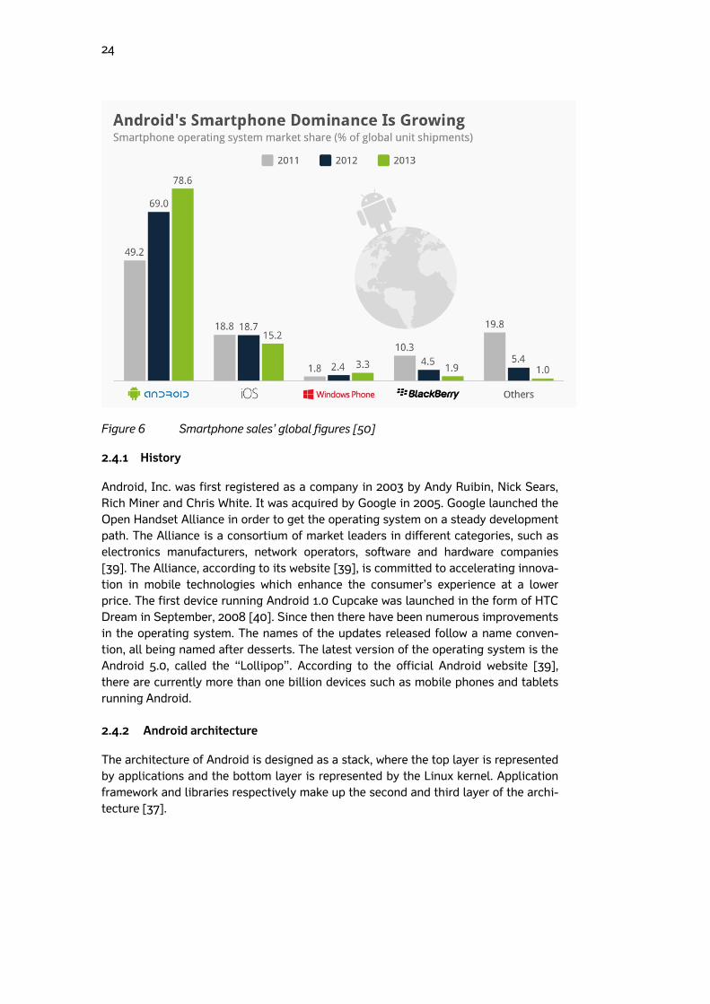
Figure 7 Android architecture [38]
Applications: The applications on the platform are coded in the Java lan-guage. By default, the operating system is shipped with a set of applications such as an SMS app, a calendar, a browser, maps, etc. [37].
Application framework: The software framework for the applications to work on that specific operating system. The framework APIs are open to applica-tions developed by developers, just like they are for the native applications. The application architecture is designed in such a way that reusability of the components is easy. With the help of content providers and managers, capa-bilities of one application can be used by other applications [37].
Libraries: This includes various libraries which are used by different compo-nents of the Android system. These are written in C/C++ language [37].
Kernel: This is the abstraction layer between the software and the hardware. If any change has to be made in the hardware, such as a volume or brightness change, the software sends a request to the kernel. Android uses kernel ver-sion 2.6 for all core operations such as memory management, process man-agement, network stack and driver model [37]. Without a kernel in place, the developers would have to write code for every activity they want to induce in the hardware, but with the kernel all requests go through the Android APIs [36].
26
2.4.3 Android for developers
Applications in Android are coded in the Java programming language using the An-droid development tools. The tools are available as a plug-in to various software de-velopment environments such as Eclipse, Android Studio, etc. Java used for pro-gramming the applications is a modified version, as Android does not support all the credentials of standard Java. Android does not support some Java libraries, such as the user interface libraries; for this, it has its own customized libraries. The entire ready-to-use user interface components support the Android user interface libraries [49]. The applications are made to run in their own instances of the Dalvik virtual ma-chine. Dalvik is so programmed that it can create multiple instances when needed, encouraging multiple applications at the same time. The Dalvik VM files are opti-mized for minimal memory footprint and executed in Dalvik executable format (.dex) [36]. The Dalvik machine relies on Linux kernel for handling some functions, such as low-level memory management and threading [49]. 2.4.4 Native Android development
The NDK (native development kit) allows developers to run native code in the Android application environment for developing Android applications. When Java code runs in the Android environment, it needs to be complied into bytecode first and then inter-preted by a virtual machine, whereas native code runs directly on the processor. NDK offers a way to code partially or fully in C/C++ [49].
2.5 Architecture
This section describes the architecture of the application as well as the system of which the application is a part. 2.5.1 Application architecture
Development of the architecture in Android does not follow a standardized procedure, as every individual is free to implement the kind of architecture they want their appli-cation to have. Individual applications in Android have individual architectures. Most of the successful applications in Android follow a modified MVC (Model-View-Controller) pattern [47]. A number of web and Windows applications have been suc-cessfully implementing MVC architecture guidelines till now, but it is not possible to implement MVC on Android without some modifications. In a proper MVC framework, controllers are able to manage multiple views; whereas in Android, activities are sin-gleton in nature, as only one activity may run at a time [46]. There are several other limitations which prevent the controllers in Android from performing all the duties of a real MVC pattern. Though Google has not endorsed MVC officially, software teams around the globe have been implementing modified versions of it. They achieved high success rates with their applications as MVC helped them in distinguishing between various components of the application and making them work [46].
27
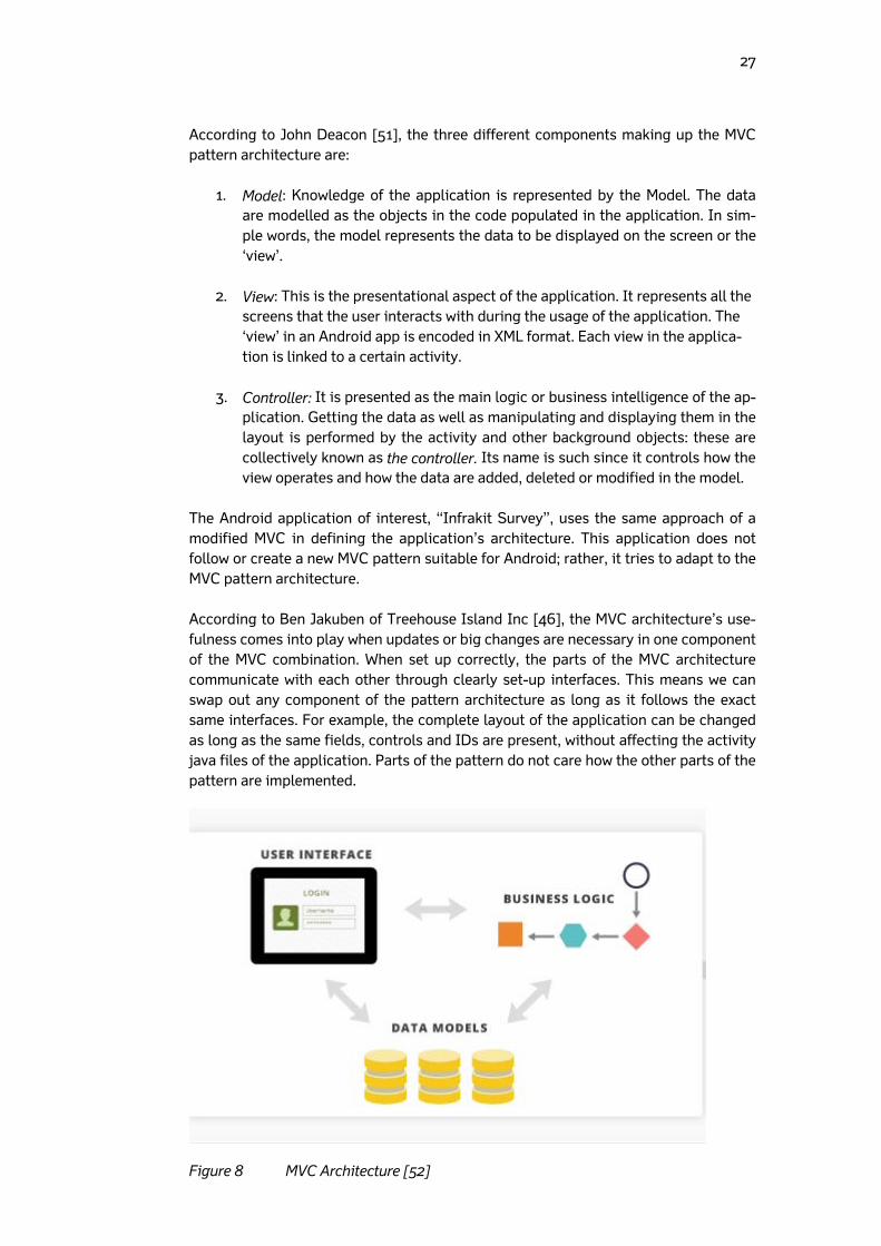
According to John Deacon [51], the three different components making up the MVC pattern architecture are:
1. Model: Knowledge of the application is represented by the Model. The data are modelled as the objects in the code populated in the application. In sim-ple words, the model represents the data to be displayed on the screen or the ‘view’.
2. View: This is the presentational aspect of the application. It represents all the
screens that the user interacts with during the usage of the application. The ‘view’ in an Android app is encoded in XML format. Each view in the applica-tion is linked to a certain activity.
3. Controller: It is presented as the main logic or business intelligence of the ap-plication. Getting the data as well as manipulating and displaying them in the layout is performed by the activity and other background objects: these are collectively known as the controller. Its name is such since it controls how the view operates and how the data are added, deleted or modified in the model.
The Android application of interest, “Infrakit Survey”, uses the same approach of a modified MVC in defining the application’s architecture. This application does not follow or create a new MVC pattern suitable for Android; rather, it tries to adapt to the MVC pattern architecture. According to Ben Jakuben of Treehouse Island Inc [46], the MVC architecture’s use-fulness comes into play when updates or big changes are necessary in one component of the MVC combination. When set up correctly, the parts of the MVC architecture communicate with each other through clearly set-up interfaces. This means we can swap out any component of the pattern architecture as long as it follows the exact same interfaces. For example, the complete layout of the application can be changed as long as the same fields, controls and IDs are present, without affecting the activity java files of the application. Parts of the pattern do not care how the other parts of the pattern are implemented.
Figure 8 MVC Architecture [52]
28
Our surveyor application can be broken down in terms of the MVC architecture.
1. View: User Interface The files which are present inside the layout folder are part of this component, such as Activity_main.xml (includes the code of the main screen of the application) Login.xml Logpoint.xml Popup.xml Settings.xml
2. Controller: Business Logic The Java files of the application responsible for connecting data to the view are part of this component of the architecture. This part draws the logic to display the data in the user interface of the application.
3. Model: Data The data generated by the application and the data stored on the server in the cloud are represented by this part of the architecture. 2.5.2 System Architecture
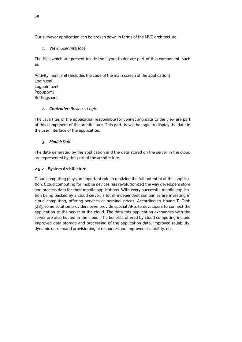
Cloud computing plays an important role in realizing the full potential of this applica-tion. Cloud computing for mobile devices has revolutionized the way developers store and process data for their mobile applications. With every successful mobile applica-tion being backed by a cloud server, a lot of independent companies are investing in cloud computing, offering services at nominal prices. According to Hoang T. Dinh [48], some solution providers even provide special APIs to developers to connect the application to the server in the cloud. The data this application exchanges with the server are also hosted in the cloud. The benefits offered by cloud computing include improved data storage and processing of the application data, improved reliability, dynamic on-demand provisioning of resources and improved scalability, etc.
29
Figure 9 Cloud computing architecture [48]
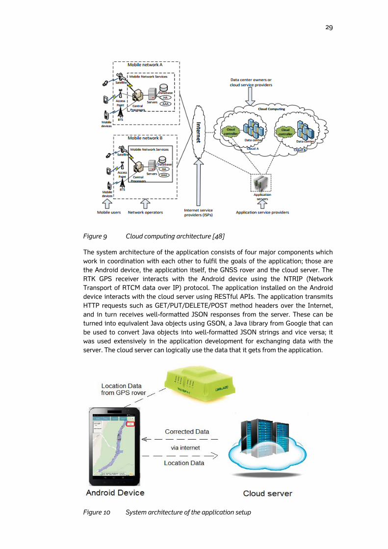
The system architecture of the application consists of four major components which work in coordination with each other to fulfil the goals of the application; those are the Android device, the application itself, the GNSS rover and the cloud server. The RTK GPS receiver interacts with the Android device using the NTRIP (Network Transport of RTCM data over IP) protocol. The application installed on the Android device interacts with the cloud server using RESTful APIs. The application transmits HTTP requests such as GET/PUT/DELETE/POST method headers over the Internet, and in turn receives well-formatted JSON responses from the server. These can be turned into equivalent Java objects using GSON, a Java library from Google that can be used to convert Java objects into well-formatted JSON strings and vice versa; it was used extensively in the application development for exchanging data with the server. The cloud server can logically use the data that it gets from the application.
Figure 10 System architecture of the application setup
30
2.6 Application as a part of Internet of Things environment
Until recently, the only communication through the Internet was human-to-human, such as communicating with each other via various applications. The Internet, how-ever, not only consists of humans triggering communications but also includes a number of devices in its ecosystem. Nowadays, a new Internet is emerging in which devices communicate with each other without a human triggering the communication; this Internet is called the Internet of Things (IOT) [54]. The communications possible are human-to-thing, thing-to-thing and human-to-human. The Internet of Things con-sists of various smart objects or devices embedded with sensors that collect data and communicate with the physical world. For example, lights in a home can monitor the activity in the room, switching themselves off when they detect nobody in the room, thus saving energy. The air conditioner can automatically switch on when it senses a car approaching the house, with the sensor in the car sending location information. All the ‘things’, such as the car and the air conditioner, are interacting with each other without human intervention. The Internet of Things is not just a theory: in fact, there are a number of applications performing these actions. The ‘things’ need to be identified in the Internet of Things world before they can be given a task. For this, RFID (Radio Frequency Identification) technology is used. RFID employs radio signals to identify items; it can also get real-time data from devices, such as location and status. The ‘things’ are fitted with sensors that support RFID communication [54]. The Internet of Things is further divided into a number of categories depending upon the area the applications serve, one of them is the Internet of Industrial things. This is the area where our Android application functions. The whole setup of communication between the Android device, GNSS rover and the cloud fits perfectly into the Internet of Industrial things environment. According to Accenture [53], devices which help in improving workflow processes and making informed decisions represent the future of the Internet of Industrial things. The basic principle for this environment is that machines are an active part of the business process and that the product is less important than the information it car-ries. The surveying application at the centre of this thesis is able to perform functions common to devices within the IIOT environment. In particular, it helps in improving the workflow of the construction process by showing accurate measurements quickly, and assists in sharing information irrespective of the devices, such as showing accu-rate designs.
31
3 Methods and development process
This chapter describes the work methods used in the thesis. It also covers the gather-ing of development-related information in the initial stages and how the actual devel-opment was carried out, discussing the techniques applied to elicit information from various participants throughout the period of the thesis.
3.1 Developing the application
The process of developing a mobile application consists of a number of steps. Agile software methodology was used during the development of the application. It was made possible following the fundamental steps of gathering requirements, designing the application, implementing and maintaining it.
Idea of the application: The basic idea behind this application is credited to various on-site and hand-held computers used by land surveyors. The pur-pose was to alleviate the highly costly and time-consuming process of land surveying on a built structure in the road construction process. The develop-ers of the application sought a solution which can use the existing everyday technology and still perform the task as precisely as a hand-held computer.
Gathering requirements: After the motivation for developing the application was identified, the next step was to gather requirements. The idea was pre-sented to a number of Finnish construction companies, and the response from them was highly positive. The GNSS receiver plays a crucial role in the operation of the application; the idea was also presented to Finnish importers of GNSS receivers as well. Their response was also encouraging. The views of both industries paved the way for feasible requirements. Functional and non-functional requirements were gathered and features of the application were determined.
Design and development of the application: Good designs help in avoiding
mistakes and complexity by displaying the positive aspects of the application. The designs undergo an iterative change as the first designs might not be correct. In case of this application, the design of the user interface also un-derwent a change, and this change has been discussed in the results section of the thesis. The application’s design was developed with simplicity, con-sistency, performance and ease of use in mind. It had to satisfy all of these in order to be successful with the user. The application is still evolving, so less attention was paid to designing the controls.
In the development, work started on developing the features that were decided at the end of the requirements-based gathering and analyzing phase. The development in-cluded deciding which Map API is to be used for showing the map, connecting the ex-ternal GNSS rovers with the application, and performing the calculations to imple-ment the selected features.
32
Selecting a Map API: The map in the main activity of the application takes up a con-siderable part of the application development effort, so a map API which offers suffi-cient features – yet is easy to implement – was needed. There were different options that the development team looked into, such as Google Maps API, Open Street Maps API, JavaScript Maps API, etc. After considering the pros and cons of each solution, the Google Maps API was chosen for the following reasons:
Google Maps are optimized for mobile usage and offer better performance as compared to any other solution.
Using the native maps API of Google, the basic features of the maps interface, such as pinching and zooming, can be implemented without much effort and are easy to customize. The other options, such as Open Street Maps, do not offer simple APIs; a separate effort is needed to produce the APIs and then develop the application using the APIs. With Google Maps demanding less time and skills, it was the preferred choice of the team.
Google Maps offer a professional interface for mobile applications. It includes easily implemented markers and easy-to-load images on the map using a dedicated API, etc. These are essential features that a business mobile appli-cation needs.
The drawbacks of the chosen API are as follows:
The Google Maps API is closed source whereas other options such as Open Street Maps are open source, allowing their users to edit or change map op-tions.
Google Maps API is not free for businesses; the user has to pay a fee if the API usage reaches 2500 calls a day. But this was not a concern for the team.
Google maps for mobiles cannot be embedded in a web view: they need an ac-tivity to get displayed.
For connecting the GNSS rover with the Android application, a Javad Triumph 2 GNSS rover which can be connected with the Android device through Bluetooth was used. The rover gets all the location-related data, such as latitude and longitude, and pass-es them to the Android application. An NTRIP client which follows the NTRIP (Net-work Transport of RCTM data over IP) protocol was employed in getting the RTK data from the rover, and vice versa.
3.2 Application interface and components
3.2.1 Application interface design principles
With the arrival of a number of Android devices, all having different specifications and screen sizes, it has been a challenge for developers to design applications that run smoothly on them all. The application draws maps in the main activity, which displays all of the important information the user is interested in. The application also con-tains some user controls such as buttons on the screen, which perform certain func-tions when pressed. When testing it on small devices, it was found quite difficult to
33
view the information, as most of the screen was occupied with user controls. The ap-plication should therefore be used on tablets with a screen size more than seven inch-es. Android comes with a number of ready-to-use UI components which can be used in the application just by dragging and dropping in the graphical layout editor of the Eclipse SDK. The developer can edit the controls or code new controls in the XML lay-out editor. The interface was designed keeping in mind the user’s need for a simple, yet powerful interface. 3.2.2 Components of the application
This section describes the various functions of the controls displayed in the main ac-tivity of the application.
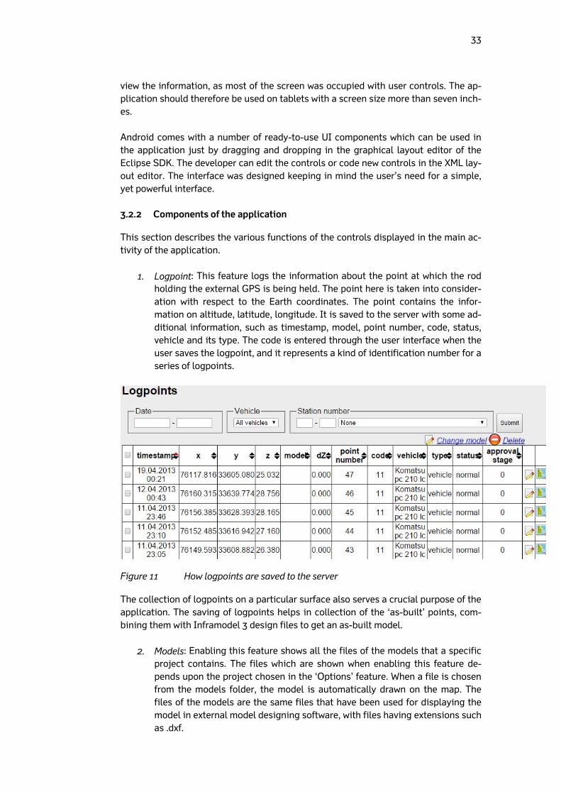
1. Logpoint: This feature logs the information about the point at which the rod holding the external GPS is being held. The point here is taken into consider-ation with respect to the Earth coordinates. The point contains the infor-mation on altitude, latitude, longitude. It is saved to the server with some ad-ditional information, such as timestamp, model, point number, code, status, vehicle and its type. The code is entered through the user interface when the user saves the logpoint, and it represents a kind of identification number for a series of logpoints.
Figure 11 How logpoints are saved to the server
The collection of logpoints on a particular surface also serves a crucial purpose of the application. The saving of logpoints helps in collection of the ‘as-built’ points, com-bining them with Inframodel 3 design files to get an as-built model.
2. Models: Enabling this feature shows all the files of the models that a specific project contains. The files which are shown when enabling this feature de-pends upon the project chosen in the ‘Options’ feature. When a file is chosen from the models folder, the model is automatically drawn on the map. The files of the models are the same files that have been used for displaying the model in external model designing software, with files having extensions such as .dxf.
34
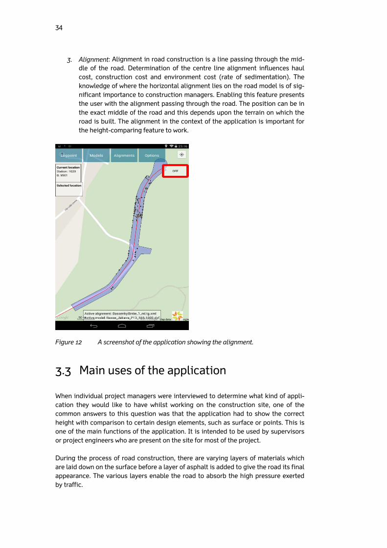
3. Alignment: Alignment in road construction is a line passing through the mid-dle of the road. Determination of the centre line alignment influences haul cost, construction cost and environment cost (rate of sedimentation). The knowledge of where the horizontal alignment lies on the road model is of sig-nificant importance to construction managers. Enabling this feature presents the user with the alignment passing through the road. The position can be in the exact middle of the road and this depends upon the terrain on which the road is built. The alignment in the context of the application is important for the height-comparing feature to work.
Figure 12 A screenshot of the application showing the alignment.
3.3 Main uses of the application
When individual project managers were interviewed to determine what kind of appli-cation they would like to have whilst working on the construction site, one of the common answers to this question was that the application had to show the correct height with comparison to certain design elements, such as surface or points. This is one of the main functions of the application. It is intended to be used by supervisors or project engineers who are present on the site for most of the project. During the process of road construction, there are varying layers of materials which are laid down on the surface before a layer of asphalt is added to give the road its final appearance. The various layers enable the road to absorb the high pressure exerted by traffic.
35
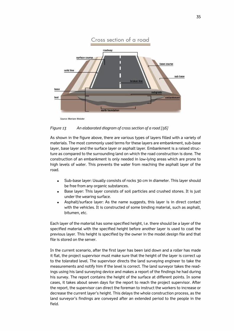
Figure 13 An elaborated diagram of cross section of a road [56]
As shown in the figure above, there are various types of layers filled with a variety of materials. The most commonly used terms for these layers are embankment, sub-base layer, base layer and the surface layer or asphalt layer. Embankment is a raised struc-ture as compared to the surrounding land on which the road construction is done. The construction of an embankment is only needed in low-lying areas which are prone to high levels of water. This prevents the water from reaching the asphalt layer of the road.
Sub-base layer: Usually consists of rocks 30 cm in diameter. This layer should be free from any organic substances.
Base layer: This layer consists of soil particles and crushed stones. It is just under the wearing surface.
Asphalt/surface layer: As the name suggests, this layer is in direct contact with the vehicles. It is constructed of some binding material, such as asphalt, bitumen, etc.
Each layer of the material has some specified height, i.e. there should be a layer of the specified material with the specified height before another layer is used to coat the previous layer. This height is specified by the owner in the model design file and that file is stored on the server. In the current scenario, after the first layer has been laid down and a roller has made it flat, the project supervisor must make sure that the height of the layer is correct up to the tolerated level. The supervisor directs the land surveying engineer to take the measurements and notify him if the level is correct. The land surveyor takes the read-ings using his land surveying device and makes a report of the findings he had during his survey. The report contains the height of the surface at different points. In some cases, it takes about seven days for the report to reach the project supervisor. After the report, the supervisor can direct the foreman to instruct the workers to increase or decrease the current layer’s height. This delays the whole construction process, as the land surveyor’s findings are conveyed after an extended period to the people in the field.
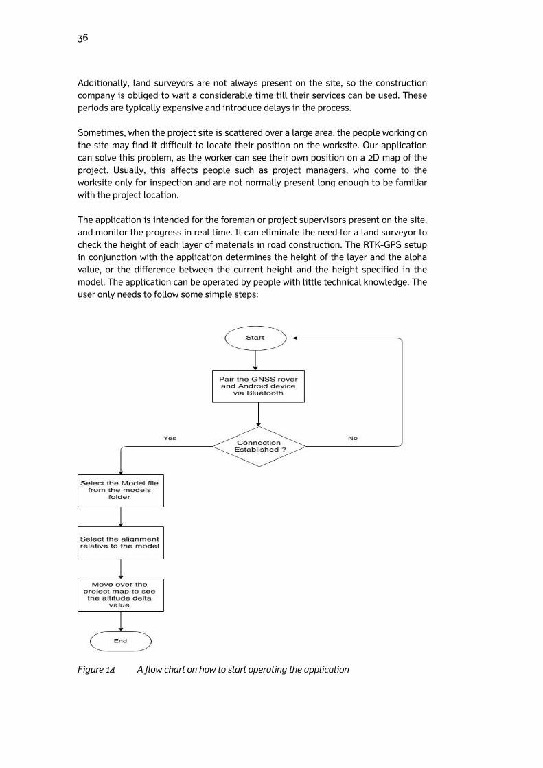
36
Additionally, land surveyors are not always present on the site, so the construction company is obliged to wait a considerable time till their services can be used. These periods are typically expensive and introduce delays in the process. Sometimes, when the project site is scattered over a large area, the people working on the site may find it difficult to locate their position on the worksite. Our application can solve this problem, as the worker can see their own position on a 2D map of the project. Usually, this affects people such as project managers, who come to the worksite only for inspection and are not normally present long enough to be familiar with the project location. The application is intended for the foreman or project supervisors present on the site, and monitor the progress in real time. It can eliminate the need for a land surveyor to check the height of each layer of materials in road construction. The RTK-GPS setup in conjunction with the application determines the height of the layer and the alpha value, or the difference between the current height and the height specified in the model. The application can be operated by people with little technical knowledge. The user only needs to follow some simple steps:
Figure 14 A flow chart on how to start operating the application
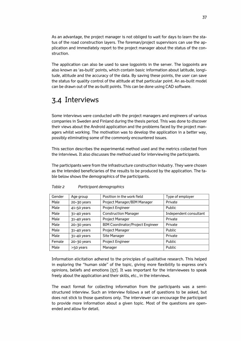
37
As an advantage, the project manager is not obliged to wait for days to learn the sta-tus of the road construction layers. The foreman/project supervisors can use the ap-plication and immediately report to the project manager about the status of the con-struction. The application can also be used to save logpoints in the server. The logpoints are also known as ‘as-built’ points, which contain basic information about latitude, longi-tude, altitude and the accuracy of the data. By saving these points, the user can save the status for quality control of the altitude at that particular point. An as-built model can be drawn out of the as-built points. This can be done using CAD software.
3.4 Interviews
Some interviews were conducted with the project managers and engineers of various companies in Sweden and Finland during the thesis period. This was done to discover their views about the Android application and the problems faced by the project man-agers whilst working. The motivation was to develop the application in a better way, possibly eliminating some of the commonly encountered issues. This section describes the experimental method used and the metrics collected from the interviews. It also discusses the method used for interviewing the participants. The participants were from the infrastructure construction industry. They were chosen as the intended beneficiaries of the results to be produced by the application. The ta-ble below shows the demographics of the participants.
Table 2 Participant demographics
Gender Age group Position in the work field Type of employer
Male 20–30 years Project Manager/BIM Manager Private
Male 41–50 years Project Engineer Public
Male 31–40 years Construction Manager Independent consultant
Male 31–40 years Project Manager Private
Male 20–30 years BIM Coordinator/Project Engineer Private
Male 31–40 years Project Manager Public
Male 31–40 years Site Manager Private
Female 20–30 years Project Engineer Public
Male >50 years Manager Public
Information elicitation adhered to the principles of qualitative research. This helped in exploring the “human side” of the topic, giving more flexibility to express one’s opinions, beliefs and emotions [57]. It was important for the interviewees to speak freely about the application and their skills, etc., in the interviews. The exact format for collecting information from the participants was a semi-structured interview. Such an interview follows a set of questions to be asked, but does not stick to those questions only. The interviewer can encourage the participant to provide more information about a given topic. Most of the questions are open-ended and allow for detail.
38
The interviews conducted were one-to-one, since we wanted to know about the atti-tude and reaction of each individual regarding the software. Besides, people in a vari-ety of managerial positions with very different understandings have been interviewed, so this technique was particularly appropriate. The interviews did not have a fixed du-ration; they took 30 minutes on average. They were held at the respective offices of the participants. To extract maximum benefit from the interview, two types of questions were asked [58]. Open questions were posed to elicit detailed information and experience from the participant. These questions concerned the problems and experiences in the work field. Closed questions determined the skill levels of the interviewee. The questions had to be answered with a rating on a scale of 1 (beginner level) to 5 (expert level), or by de-claring no skill level at all. Using both question types in a single questionnaire allowed the interviewer to get the most information in a short time. This also satisfied the fundamental conditions of qualitative research, since participants were able to express themselves freely. Alt-hough the structure of the questionnaire was the same for every person to be inter-viewed, some questions were not included in the final interview, depending upon the person. All the interviews followed the same procedure. Upon arranging an appointment for the interview, some basic details on the subject were written down. Once a basic un-derstanding of the application and the company was provided, the interview proceed-ed based on the question set, with the responses written down and occasionally rec-orded using a voice recorder. The parameters investigated during the interview included challenges in communica-tion with other stakeholders during work, skill levels in various construction industry-related technologies, and advantages (usage scenarios) of the Android application on the worksite. English was used for preparing the questionnaire and interviewing the participants. A number of project managers from a number of infrastructure construction organiza-tions were invited for the interviews, but as English was to be used for interviewing, a considerable number of responses were negative. This was due to the fact that Finn-ish is the primary language of all infrastructure construction organizations in Finland. It was a challenge to find people who also had suitable expertise in the field.

39
4 Results
This chapter discusses the results of the interviews that were conducted to learn about the participants’ opinions on the Android application and the problems they face in the work field.
4.1 Skill level in related technologies
The participants were asked questions regarding the level of skills they possess in certain fields or technologies. The technologies about which they were asked are re-lated to the application covered above. This was accomplished by asking closed ques-tions in the interview. The skills investigated were:
Experience with machine control systems: The participants were asked if they had experience of operating machine control systems. A total of 33% of all participants had no such knowledge about the system. Of the remaining ones, 50% rated their skill level at 3 or less.
Figure 15 Experience with Machine Control Systems
Experience with BIM (Building Information Modelling): The Android appli-
cation has been based on the methodology of BIM, so it was important to ask the participants about their experience of working with BIM in a project. All the respondents reported that they had knowledge about BIM and its work process; 66% of them claimed their individual skill rating of BIM to be 3 or less than 3.
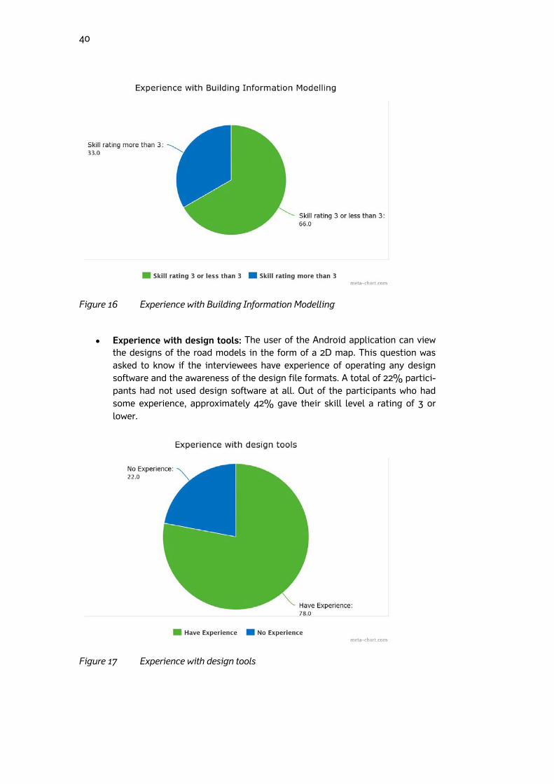
40
Figure 16 Experience with Building Information Modelling
Experience with design tools: The user of the Android application can view
the designs of the road models in the form of a 2D map. This question was asked to know if the interviewees have experience of operating any design software and the awareness of the design file formats. A total of 22% partici-pants had not used design software at all. Out of the participants who had some experience, approximately 42% gave their skill level a rating of 3 or lower.
Figure 17 Experience with design tools
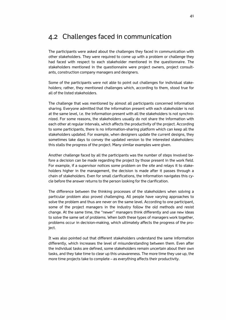
41
4.2 Challenges faced in communication
The participants were asked about the challenges they faced in communication with other stakeholders. They were required to come up with a problem or challenge they had faced with respect to each stakeholder mentioned in the questionnaire. The stakeholders mentioned in the questionnaire were project owners, project consult-ants, construction company managers and designers. Some of the participants were not able to point out challenges for individual stake-holders; rather, they mentioned challenges which, according to them, stood true for all of the listed stakeholders. The challenge that was mentioned by almost all participants concerned information sharing. Everyone admitted that the information present with each stakeholder is not at the same level, i.e. the information present with all the stakeholders is not synchro-nized. For some reasons, the stakeholders usually do not share the information with each other at regular intervals, which affects the productivity of the project. According to some participants, there is no information-sharing platform which can keep all the stakeholders updated. For example, when designers update the current designs, they sometimes take days to convey the updated version to the interested stakeholders: this stalls the progress of the project. Many similar examples were given. Another challenge faced by all the participants was the number of steps involved be-fore a decision can be made regarding the project by those present in the work field. For example, if a supervisor notices some problem on the site and relays it to stake-holders higher in the management, the decision is made after it passes through a chain of stakeholders. Even for small clarifications, the information navigates this cy-cle before the answer returns to the person looking for the clarification. The difference between the thinking processes of the stakeholders when solving a particular problem also proved challenging. All people have varying approaches to solve the problem and thus are never on the same level. According to one participant, some of the project managers in the industry follow the old methods and resist change. At the same time, the “newer” managers think differently and use new ideas to solve the same set of problems. When both these types of managers work together, problems occur in decision-making, which ultimately affects the progress of the pro-ject. It was also pointed out that different stakeholders understand the same information differently, which increases the level of misunderstanding between them. Even after the individual tasks are defined, some stakeholders remain uncertain about their own tasks, and they take time to clear up this unawareness. The more time they use up, the more time projects take to complete – as everything affects their productivity.
42
4.3 Tools used on the site during work
The term ‘tool’ used here refers to any device or instrument which helps in performing work in the field. All of the participants use laptops for work, while 55% of them addi-tionally use tablets. When asked about the various software used at work, products such as Tekla BIM Sight, CAD Viewer, Microsoft Office, Solibri, Infrakit, and timeta-ble-scheduling software were mentioned. Of all these tools, 80% of the participants use Microsoft Office the most during their work. It has been primarily used for the basic purpose of storing information regard-ing the project, such as information about materials used, timetables, etc. Virtually all the information is viewed or edited using Microsoft Office. A total of 44% of the re-spondents mentioned Tekla BIM as their second most used software. It is an instance of project portal software used for viewing road designs and models in 2D and 3D.
4.4 Information most interesting to participants
Participants were asked what kind of information they received from other stakehold-ers or colleagues working on the site and what kind of information they were most interested in. Most of the participants interviewed are project managers in their re-spective organizations, they gather a lot of information regarding the project from their colleagues, superiors and other stakeholders, and it was important to observe how they utilize the information.
The project managers (owners) get reports on the progress of the project from other stakeholders after a certain period of time. These reports are con-sidered the most important information exchanged between the active stake-holders. They contain facts and figures related to the project, such as the quantities of materials used, the time for which the work was done, the prob-lems faced, future plans, and so on. There are a number of things that can be listed in such a report, and it does not follow a fixed format.
The report helps the project managers in reviewing the structure that has been built till now. The process of creating of the report starts from the con-struction company manager, who collects and lists all the information in the report. The report is then sent to the construction consultant, who verifies all the information and clarifies the details with the construction company man-ager if needed. After the construction consultant is satisfied, the report is sent to the project manager (owners). The report also helps in predicting which problems the construction company may face in the future.
The project managers are interested in the timetable of the project. A timeta-
ble consists of future estimations from the construction company as to what structure of the project will be completed by what time. The project managers would like to follow that timetable throughout the project whilst looking out for delays. A timetable will also help them in planning the future phases of the project.
43
The project managers are also interested in applications that can help them in reviewing the correctness of a built structure. In some projects, a number of construction companies are involved, i.e. when one company finishes a cer-tain part of the project, the other company takes over to complete the project. The second company has to carry out certain measurements on the finalized structure to understand if the structure has been built correctly. These meas-urements consume a lot of time and resources. The company managers would thus prefer tools that can help them take quick measurements and receive re-sults shortly; this will help them speed up the development of the structure.
4.5 Views on the Android application
The participants were asked certain questions regarding the application developed within this thesis. Specifically, they were asked if they would like to have an applica-tion which shows a 2D map of the model and an accurate location of themselves when they are present on the field. The participants were also asked whether they would be helped by software which shows height in comparison to design elements such as sur-face or points. The responses to both of these questions were positive from all of the participants, and they showed considerable interest in the functioning of the applica-tion.

44
5 Testing and implementation of the application
This chapter describes the improvements made in the application during the duration of the thesis and how the application was tested in a real working environment.
5.1 Implementation
To make the application more user-friendly, some modifications were made to it. The Infrakit company had already tested the existing application in a real work environ-ment. The improvements to be made during the thesis period were suggested by the company operating the application at this time.
User interface of the application: During the testing of the application in a real work environment with the initial UI, it was observed that users were facing some difficulties in operating the user interface of the application. Specifical-ly, the UI elements of the application such as buttons and text fields were found to be irresponsive at times, due to the small size of the controls and the lighting on the worksite. The buttons on the top action bar of the screen were irresponsive due to their small size. To remedy this problem, the action bar was removed from the application. Moreover, the controls were deemed big in size as compared to the previous ones. To make sure the controls do not ob-scure the information on the map, they were made 60% transparent. Also, a number of other controls were merged to make way for new compact controls, such as an ON/OFF button to show or remove connection-related information on the screen. The UI of the application is easy to use with self-explanatory control labels.
Figure 18 A screen shot of the first screen of the application
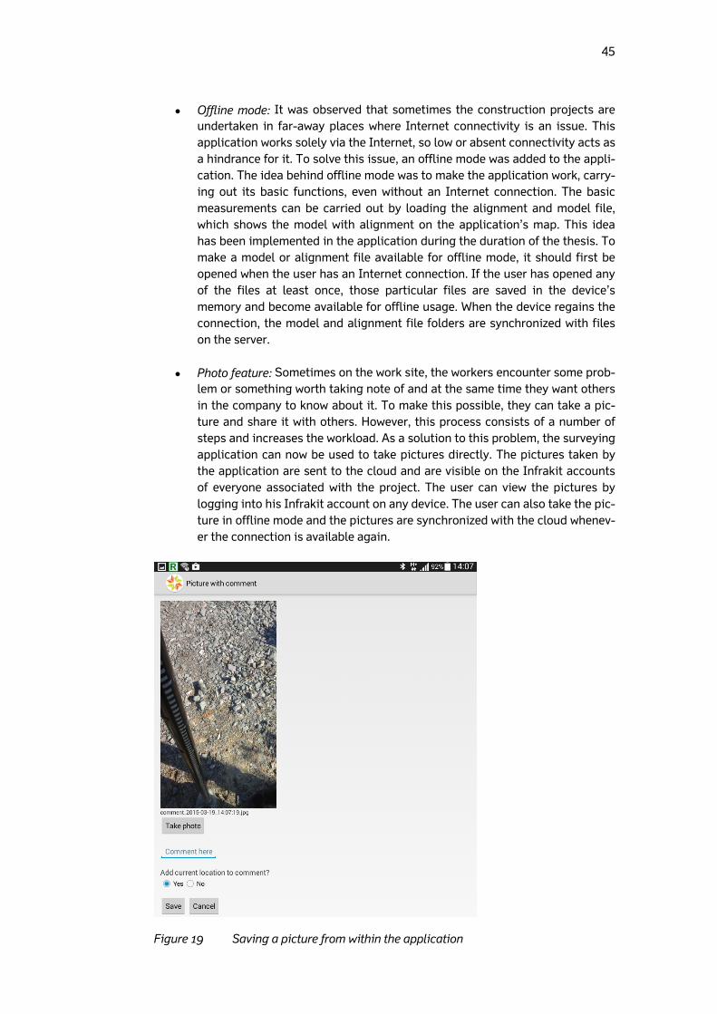
45
Offline mode: It was observed that sometimes the construction projects are undertaken in far-away places where Internet connectivity is an issue. This application works solely via the Internet, so low or absent connectivity acts as a hindrance for it. To solve this issue, an offline mode was added to the appli-cation. The idea behind offline mode was to make the application work, carry-ing out its basic functions, even without an Internet connection. The basic measurements can be carried out by loading the alignment and model file, which shows the model with alignment on the application’s map. This idea has been implemented in the application during the duration of the thesis. To make a model or alignment file available for offline mode, it should first be opened when the user has an Internet connection. If the user has opened any of the files at least once, those particular files are saved in the device’s memory and become available for offline usage. When the device regains the connection, the model and alignment file folders are synchronized with files on the server.
Photo feature: Sometimes on the work site, the workers encounter some prob-lem or something worth taking note of and at the same time they want others in the company to know about it. To make this possible, they can take a pic-ture and share it with others. However, this process consists of a number of steps and increases the workload. As a solution to this problem, the surveying application can now be used to take pictures directly. The pictures taken by the application are sent to the cloud and are visible on the Infrakit accounts of everyone associated with the project. The user can view the pictures by logging into his Infrakit account on any device. The user can also take the pic-ture in offline mode and the pictures are synchronized with the cloud whenev-er the connection is available again.
Figure 19 Saving a picture from within the application
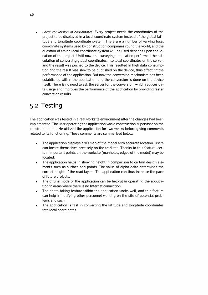
46
Local conversion of coordinates: Every project needs the coordinates of the project to be displayed in a local coordinate system instead of the global lati-tude and longitude coordinate system. There are a number of varying local coordinate systems used by construction companies round the world, and the question of which local coordinate system will be used depends upon the lo-cation of the project. Until now, the surveying application performed the cal-culation of converting global coordinates into local coordinates on the server, and the result was pushed to the device. This resulted in high data consump-tion and the result was slow to be published on the device, thus affecting the performance of the application. But now the conversion mechanism has been established within the application and the conversion is done on the device itself. There is no need to ask the server for the conversion, which reduces da-ta usage and improves the performance of the application by providing faster conversion results.
5.2 Testing
The application was tested in a real worksite environment after the changes had been implemented. The user operating the application was a construction supervisor on the construction site. He utilized the application for two weeks before giving comments related to its functioning. These comments are summarized below:
The application displays a 2D map of the model with accurate location. Users can locate themselves precisely on the worksite. Thanks to this feature, cer-tain important points on the worksite (manholes, edges of the model) may be located.
The application helps in showing height in comparison to certain design ele-ments such as surface and points. The value of alpha delta determines the correct height of the road layers. The application can thus increase the pace of future projects.
The offline mode of the application can be helpful in operating the applica-tion in areas where there is no Internet connection.
The photo-taking feature within the application works well, and this feature can help in notifying other personnel working on the site of potential prob-lems and such.
The application is fast in converting the latitude and longitude coordinates into local coordinates.
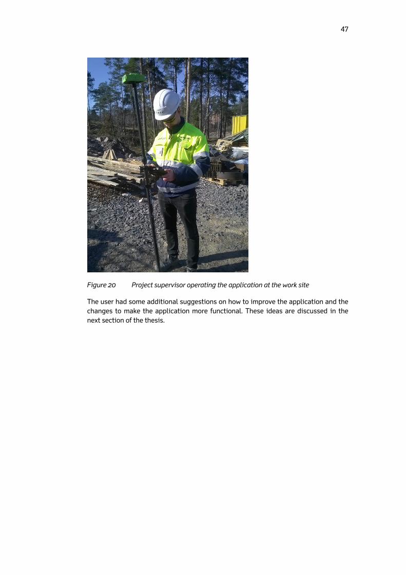
47
Figure 20 Project supervisor operating the application at the work site
The user had some additional suggestions on how to improve the application and the changes to make the application more functional. These ideas are discussed in the next section of the thesis.
48
6 Discussion, conclusion and future work
This chapter discusses the results of the interviews, conclusion of the thesis and the future of this research.
6.1 Analysis of interview results
The results of the interviews not only suggest that the surveying application will have a good place in the construction market in the future, but also showcase various dif-ferences and problems which lead to ineffective stakeholder communication in the Nordic construction environment.
The majority of the participants of the interviews occupied the position of project managers or project engineers in their respective organizations. A project manager is a very important stakeholder within the context of a con-struction project, and improving their productivity can benefit the whole pro-ject. The results can help in understanding the needs and the problems they face. Although the number of project managers interviewed is not so signifi-cant, the results can act as a good starting point in formulating a solution to those problems in future.
The results suggest that the tools used by project managers are not effective enough to help them be more efficient in their work. Most tools used are sim-ple document editing tools, such as MS Office, and only a small number uses professional BIM-related tools. However, it was found that they were not fully aware of the functions of the professional BIM tools. Most of the participants do not have previous experience of using any professional tool. Their re-sponses to the interview questions suggest that providing them with ad-vanced tools and adequate training can help them solve a number of prob-lems.
All the participants know about Building Information Modelling; two-thirds of them, whilst being aware of the term, do not fully understand its implementa-tion in the project. They seemed unsure of how to extract the benefit of BIM in a project.
In some projects, there are too many steps involved before a decision is made. The participants are not in favour of this long chain, but they cannot change this system by themselves. This delay in making the decision is cru-cial to the speed at which the project progresses.
Most of the participants believed that project progress reports, despite being a good source of information on the progress of the project and being pre-ferred by project managers, are not consistent. No consistent routine of pre-paring such reports is generally followed by the stakeholders. The progress report meetings are not consistent according to 90% of the participants. Sometimes the gap between these progress report meetings is several months.
49
Timetables of the projects are supposed to be followed by all stakeholders for timely progress of the project. However, this concept appears not to be fol-lowed by construction companies in practice. Whether the timetable is pre-sented to the project manager at the start of the project depends upon the construction company and the manager’s determination.
The participants think that the Android application will be a great tool for people who monitor the progress and carry out measurements on the work field. It can help them have fast access to results, which will improve work ef-ficiency. This can also act as a good tool for project managers, who can use the tool on their site tours to locate themselves on the worksite and also check the height of the structural layers easily without having to look for data relating to the field. The simple interface of the application was liked by the participants, and they were eager to try out its functionality in a real project.
6.2 Conclusion
Information technology has been playing a bigger role than ever in various industries, and the construction industry is not different. With growing use of IT in construction projects, stakeholders in construction industries have more tools at their disposal to help them in different activities of the project. The only step to be taken is to actively adopt these technologies and reap the benefits. With this thesis, I have tried to look deep into functionality and the benefits of one of those helpful tools which will change the way construction companies work. This section summarizes the thesis by presenting the findings in relation to the re-search questions that motivated this study. It also provides insight into how the con-struction project owners such as the Finnish Transport Agency (Liikennevirasto) should proceed with the tool in the future and the improvement possibilities in this application. The main purpose of the study was to answer the following research questions:
How does having access to updated/accurate designs in real time affect the work of supervisors/project managers?
- Research suggests that the worksite users find accurate designs loaded on the application’s map interface to be very helpful. The application helps them in locating themselves accurately on the worksite. It also aids in locating physical objects on the worksite mentioned in the designs, such as finding the edge of the road in the real world.
How do the possibilities of making accurate measurements and comparing them to designs in real time help in day-to-day work done in the field by su-pervisors?
– It is clear that the supervisors at the worksites have benefitted from using this application for checking the height of the layers of the road. The value the application produces after comparing the height of the actual surface with the height of the layer specified in designs is very helpful for the supervisors and foremen. The measurements are accurate and can be compared to those received with any profes-sional land surveying equipment.
50
How does saving ‘as-built’ quality measurements help the supervisors/project managers?
– The as-built points can be saved in the form of logpoints in the appli-cation. These logpoints are stored on the server and can be used for making ad-hoc models out of the logpoints. The user at the worksite can extract the logpoints from the server and use them in designing software for making a model out of them.
Most of the project managers that were interviewed during the thesis period belonged to construction project owners such as the Finnish Transport Agency (Liikennevi-rasto). This thesis can act as a good starting point for those organizations that want to make their project managers more effective and productive by introducing them to different tools. Empowering project managers with tools will help them perform bet-ter, leading to savings in time and costs for the owner. However, it was found during the interviews that most of the project managers are unaware of the tools that are available in the market relating to BIM. It may be worth introducing them to different tools and their functions. The project managers can then be introduced to their work-specific tools and trained on those, so that they can perform their duties better by uti-lizing the power of information technology. The research on usage of BIM in road construction projects shows that the Finnish construction industry is among the leaders in world when it comes to BIM implemen-tation in their respective construction industry. However, the construction projects are far from a complete BIM implementation. Knowledge of BIM across the stake-holders varies and this is the reason why BIM is not fully implemented in projects. People are reluctant in adapting to BIM and a number of projects are still being car-ried out using traditional methods. There is still a lack of information-sharing be-tween the stakeholders, which BIM can alleviate once fully implemented. The gov-ernment should take the necessary steps to introduce all the stakeholders to BIM and its benefits before a project is commenced. Addressing this issue might help in solv-ing a number of problems that projects face. The Android application developed during the thesis period can challenge the tradi-tional work base of land surveyors. It can decrease their workload and increase the efficiency of the project by providing faster results compared to traditional land sur-veying methods. There are certain points which make it a better choice, but there were also some doubts on the accuracy of the whole setup. It was noted in various locations, however, that the application has an accuracy range of 3–20 cm. The sys-tem has the potential to reach the same accuracy as professional GNNS surveying devices and machine control systems; the accuracy depends upon the type of the GNSS rover used, not the application. The GNSS rover or the external GPS device used here is Javad Triumph-2, which is also used by professional land surveyors. The accuracy of the application also depends upon how the correction results are received by the Android application. If the correction results are delivered through a local base station, then the accuracy is between 2 to 4 cm; otherwise (via the Internet) it ranges from 3 to 20 cm. During the usage of the application in the research period, correction values were obtained via the Internet, and a commercial virtual base station service was used for the correction. The maximum deviation noted was around 10 cm from the actual value. The application can also work without the GNSS rover, as the An-droid device can use its built-in GPS. However, in that case the accuracy of the setup drops to 3 to 5 meters. The accuracy of the Android device’s GPS depends upon the
51
quality of hardware used in the device. Still, the device has been found sufficient for locating oneself on the worksite, even without the use of a GNSS rover. In brief, the following is needed for the proper functioning of the application:
An Android device, preferably running Android 4.0 or above. The size of the device should preferably be more than seven inches.
A GNSS receiver (external GPS device) paired with the Android device on which the surveying application is installed.
A rod which can support the GNSS rover on top and withstand the Android device.
Once the receiver is switched on and establishes connection with the Android device, the application is ready to use. During the research period, it was observed that the GNSS receiver can face some problems with satellite visibility and Internet connectivity, though the occurrence of such problems was very rare. Generally, receivers do not face many issues, even when used for long hours on the site. Their charge is normally the only concern. Another problem faced during the course of this thesis was the collection of infor-mation regarding the Finnish infrastructure sector. It was a language problem: Finn-ish is the main language used for documentation in every construction sector-related organization. It was therefore difficult to carry out research, as limited information was available in English. For example, websites inframodel.fi and infrabim.fi maintain important information regarding the InfraModel3 format and the usage of BIM in Fin-land’s infrastructure industry in Finland, but both are entirely in Finnish.
6.3 Future work
In the future, the tool is going to be developed further to be as easy to use as possible for non-surveyor personnel. The application might eventually challenge the profes-sional land surveying tools available for checking the height of the road layers. The application has been tested in some locations around Sweden and Finland and was found to be working satisfactorily, but the weather at those sites was not too harsh: for instance, no snow was found on the worksite. It will be interesting to observe how the application reacts when it is operated in harsh weather and the layer of the road on which measurement has to be taken is covered with snow. Taking the measure-ment in this scenario is a challenge, since snow might distort the height of the origi-nal layer. The application is evolving, and there are a number of changes that have been sug-gested by the construction supervisors using this application on a daily basis. Some of these changes are taken into account and will be implemented over time. Some of the changes which can be expected in the near future are:
Implementing all the features of the offline mode, such as making it possible to use the complete functionality of the application in the absence of an In-ternet connection, including loading the worksite map or the background.
The UI of the application is evolving and suggestions from the users are im-plemented. This will continue in the future until a suitable UI is found.
52
The ability to make the logpoints visible on the map every time the applica-tion is used. The application must be able to guide the user to these points on the site.
After the changes are implemented, it will be interesting to compare the application with other professional devices available in the market. Till now, the surveying appli-cation has been satisfactorily performing the basic functions of these devices, such as height calculation, in a simpler way. More research can be conducted in the future, comparing this setup with other professional land surveying options available in the market. It will also be interesting to see how the professional land surveyors feel about the application after all the improvements have been implemented. Their help-ful comments and suggestions can help in further refinement of the application. It has shown a lot of promise throughout this research period and can turn out to be quite an effective tool for the infrastructure construction industry. To conclude, I am hope-ful that this work and the results obtained will encourage more research in this area.
53
References
[1] Bilal Succar, “Building information modelling framework: A research and delivery foundation for industry stakeholders” Automation in Construction 18 (2009) 357–375 [2] David Bryde , Martí Broquetas , Jürgen Marc Volm, “The project benefits of Build-ing Information Modelling” International Journal of Project Management Volume 31, Issue 7, October 2013, Pages 971–980 [3] BIM topics lab University of British Columbia, “Building Information Management ‘Best Practices‘ project report”, 2011 Available: http://bimcivil.sites.olt.ubc.ca/files/2014/06/BIMBestPractices2011.pdf [4] Atul Porwal , Kasun N. Hewag, “Building Information Modeling (BIM) partnering framework for public construction projects” Automation in Construction Volume 31, May 2013, Pages 204–214 [5] Autodesk, “BIM for Infrastructure: A vehicle for business transformation” [Online]. Available: http://thebuildingcoder.typepad.com/files/bim_for_infrastructure_november_2012.pdf , 2012 [Accessed: 28-Nov-2014] [6] Fernando G. Bañuelos Blanco, Haibo Chen,” The Implementation of Building In-formation Modelling in the United Kingdom by the Transport Industry”, The 9th In-ternational Conference on Traffic and Transportation Studies (ICTTS 2014) [7] Young soo Jung , Mihee Joo, “Building information modelling (BIM) framework for practical implementation”, Automation in Construction Volume 20, Issue 2, March 2011, Pages 126–133 [8] Tomo Cerovsek ”A review and outlook for a ‘Building Information Model’ (BIM): A multi-standpoint framework for technological development” , Advanced Engineering Informatics Volume 25, Issue 2, April 2011, Pages 224–244 [9] Rob Howard ,Bo-Christer Bjo¨rk,” Building information modelling – Experts’ views on standardisation and industry deployment ”, Advanced Engineering Informatics Volume 22 Issue 2, April, 2008 Pages 271-280 [10] Han Yan, Peter Damian, “Benefits and Barriers of Building Information model-ling”.12thInternational Conference on Computing in Civil and Building Engineering Beijing, 2008 [11] Bentley, “Build as One — BIM is a new way of approaching the design and doc-umentation of building projects”, [Online]. Available: http://www.andrew.cmu.edu/user/ramesh/teaching/course/48-749/readings/bentley-build-as-one.pdf ,
[Accessed: 27-Jan- 2015]
[12] Ministry of Infrastructure and Environment, Netherlands “Virtual Construction for Roads (V-Con) 2012 [Online]. Available: http://www.rws.nl/en/highways/v_con/ [Accessed: 05-
Jan-2015]
54
[13] buildingSMART Alliance, “What are its functions, members and chapters” [Online]. Available: http://www.buildingsmart.org/ , [Accessed: 27-Jan- 2015] [14] buildingSMART Finland, “ About buildingSMART Finland”, [Online], Available: http://www.buildingsmart.fi/ [Accessed: 27-Jan- 2015]
[15] Registers of Scotland (Executive agency),”Land Surveying - Detail Survey, Intro-duction to Survey Practice” Section 5 V1.0a Apr 2004 [Online]. Available: https://drive.google.com/file/d/0B5pPOEcSZIGaRlgxckVCalhtaDg/view?usp=sharing [Accessed: 25-Oct- 2014] [16] L S, Blake,” Engineering surveying: Civil Engineer’s reference book”, 2001 [17] Adam Chrzanowski, “Modern Surveying Techniques for Mining and Civil Engi-neering”, Chapter 33 in: Comprehensive Rock Engineering, Pengamon Press, Vol 3. Chapter 33, pp. 773-809. [18] T.H. Davenport, Process Innovation: reengineering work through information technology, Harvard Business School Press, 1992. [19] W. Schofield, Mark Breach, ”Engineering Surveying, Sixth Edition”, 2007 [20] Penn State University, College of Material and Earth Sciences, ” Land Surveying and GPS” [Online]. Available: https://www.e-education.psu.edu/geog482spring2/c5.html [Accessed: 27-Dec- 2014]
[21]HowelKline Surveying LLC, ”Surveying Methods” [Online] Available: http://www.howellkline.com/surveying-methods [Accessed: 25-Oct- 2014]
[22] California Department of Transportation,”Photogrammetry surveys”, [Online] Available: http://www.dot.ca.gov/hq/row/landsurveys/SurveysManual/13_Surveys.pdf , 2006 [Ac-cessed: 29-Oct- 2014] [23] McWilliam, R. Teeuw, M. Whiteside and P. Zukowskyj for Royal Geographical So-ciety, “Field Techniques Manual: GIS GPS and Remote Sensing”, 2005 [Online] Avail-able:http://www.rgs.org/NR/rdonlyres/D5D046D8-5582-41D0-BEF8-D15A148C5D32/0/Chapter1GISGPSRemoteSensingandFieldwork.pdf [Accessed: 10-Nov-2014] [24] Hongtao Xu, “Application of GPS-RTK Technology in the Land Change Survey” 2012 International Workshop on Information and Electronics Engineering, 2012 [25] Resource Supply, LLC, “RTK (Real Time Kinematic) Basics for Surveying”, [Online], Available: http://www.resourcesupplyllc.com/pdfs/RTKBasics_SurveyGradeGPS.pdf 2008
[Accessed: 25-Oct- 2014] [26] NovAtel Inc. “Advanced GNSS techniques- Real Time Kinematic” [Online]. Avail-able: http://www.novatel.com/an-introduction-to-gnss/chapter-4-advanced-gnss-concepts/real-time-kinematic-rtk/ . [Accessed: 27-Nov-2014].
55
[27] Intergovernmental Committee on Surveying and Mapping Australia,”Surveying for mapping- Section4, Surveying using GPS and conclusion” [Online]. Available: http://www.icsm.gov.au/mapping/surveying4.html#GPS. [Accessed: 30-Nov-2014]. [28] The LandXML Project [Online]. Available: http://www.landxmlproject.org/ [Accessed: 12-Nov-2014] [29] LandXML.org [Online]. Available: http://www.landxml.org/ [Accessed: 12-Nov-2014] [30]LandXML [Online]. Available: http://giswiki.org/wiki/LandXML [Accessed: 13-Nov-2014] [31] Alexander Mabrich, Bently Civil, “Exporting Data Using LANDXML” [Online]. Available: http://www.flugsite.com/presentations/spring2006/LandXMLPresentation.pdf . [Accessed: 14-Nov-2014] [32] InfraBIM [Online]. Available: http://www.infrabim.fi/ [Accessed: 20-Nov-2014] [33] Inframodel Finland [Online]. Available: http://www.inframodel.fi/en/ [Accessed: 25-Sep-2014] [34] RYM Oy, “INFRAMODEL 3 data exchange format will come into general use” [Online]. Available: http://rym.fi/inframodel-3-data-exhange-format-will-come-into-general-
use/[Accessed:25-October-2014] [35] Infrakit Oy, “ BIM for Infrastructure Construction “ [Online]. Available: http://www.infrakit.com/documents/Infrakit_Brochure_ENG_FACING_SCREEN_2014-06-16.pdf [Accessed: 25-Nov-2014] [36] Nisarg Gandhewar, Rahila Sheikh, “Google Android: An Emerging Software Plat-form For Mobile Devices” International Journal on Computer Science and Engineering (IJCSE),2010 [37]Linux For You, “A developer’s first look at Android” [Online] Available: http://gcodebank.com/attachment/495f58525fcf7D0.pdf [Accessed: 20-Nov-2014] [38] Margaret Butler,” Android: Changing the Mobile Landscape”, IEEE Pervasive Computing, January–March 2011, pp. 4–7, 2011 [39]Open Handset Alliance [Online], Available: http://www.openhandsetalliance.com/index.html [Accessed: 3-Dec-2014] [40]A. Helal, R. Bose and W. Li, “Mobile Platforms and Development Environments,” Morgan & Claypool Publishing Company. ISBN: 9781608458660 paperback, 9781608458677 ebook, Copyrights February 2012 [41] Autodesk,”European Parliament Directive to Spur BIM adoption in 28 EU coun-tries” [Online]. Available: http://inthefold.autodesk.com/in_the_fold/2014/01/european-parliament-directive-to-spur-bim-adoption-
in-28-eu-countries.html Accessed:[05-Jan-2015]
56
[42] Tekla, “Seattle’s Massive Tunnel Makes Travel Safer – with Tekla BIMsight” [Online]. Available: http://www.tekla.com/company/news/seattles-massive-tunnel-makes-travel-safer-tekla-bimsight [Ac-cessed: 10-Jan-2015] [43] Vianova, “ QuadriDCM “ [Online]. Available: http://www.vianovasystems.com/Products/QuadriDCM/QuadriDCM#.VDKCrSgsFC8 [Accessed: 06-Feb-2015] [44] Vianova, “NovapointDCM“, [Online]. Available: http://www.vianovasystems.com/Products/NovapointDCM [Accessed: 06-Feb-2015] [45] Topcon, “SiteLink3D”, [Online]. Available: http://www.topconpositioning.com/products/software/network-applications/sitelink3d [Accessed: 06-Feb-2015] [46] Ben Jakuben, Treehouse Island Inc, “The Model-View-Controller (MVC) Design Pattern” [Online] Available: https://teamtreehouse.com/library/build-a-blog-reader-android-
app/exploring-the-masterdetail-template/the-modelviewcontroller-mvc-design-pattern-2 [Accessed: 16-Oct-2014] [47] Karina Sokolova, Marc Lemercie, Ludovic Garcia,” Android Passive MVC: a Novel Architecture Model for Android Application Development” The FIfth International Conferences on Pervasive Patterns and Applications, 2013 [48] Hoang T. Dinh, Chonho Lee, Dusit Niyato, and Ping Wang, “A Survey of Mobile Cloud Computing: Architecture, Applications, and Approaches”, Wireless Communi-cations and Mobile Computing Volume 13, Issue 18, pages 1587–1611, 25 December 2013 [49] Android , “Android Developers”, [Online] Available: http://developer.android.com/ Accessed: [Accessed: 20, November,2014] [50] International Data Corporation,”Android and iOS Continue to Dominate the Worldwide Smartphone Market with Android Shipments Just Shy of 800 Million in 2013”, [Online] Available: http://www.idc.com/getdoc.jsp?containerId=prUS24676414 [Ac-cessed: 20-Oct-2014] [51] John Deacon, “Model-View-Controller( MVC) Architecture ” [Online] Available: http://www.battersea-locksmith.co.uk/briefings/MVC.pdf [Accessed: 01, March,2015] [52] AppAcelrator, ”MVC- Rapid Mobile App development” [Online] Available: http://www.appcelerator.com/product/ [Accessed: 20, November,2014] [53] Accenture Inc,” Accenture Technology Labs: Industrial Internet Strategic Innova-tion Initiative” [Online] Available: http://www.accenture.com/us-en/Pages/service-technology-
labs-industrial-internet-strategic-innovation-initiative.aspx [Accessed: 15, February,2015] [54] Lu Tan, Neng Wang, “Future Internet: The Internet of Things” 3rd International Conference on Advanced Computer Theory and Engineering (ICACTE), 2010
57
[55] Construction, McGraw-Hill. "The business value of BIM in North America: Multi-year trend analysis and user ratings (2007-2012)." Bedford, MA: McGraw-Hill Con-struction (2012). [56]Merriam-Webster, “Visual Dictionary Online” [Online] Available: http://visual.merriam-
webster.com/transport-machinery/road-transport/road-system/cross-section-road.php [Accessed: 10, October, 2015] [57] Mack, Natasha Cynthia Woodsong, Kathleen M. MacQueen, Greg Guest, and Emi-ly Namey. 2005. Qualitative Research Methods: A Data Collector's Field Guide. Family Health International [58]University of Surrey, “Introduction to Research” [Online] Available: http://libweb.surrey.ac.uk/library/skills/Introduction%20to%20Research%20and%20Managing%20Infor
mation%20Leicester/index.htm [Accessed: 10-Mar-2015]

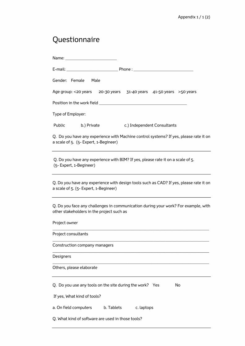
Appendix 1 / 1 (2)
Questionnaire
Name: _________________________ E-mail: _________________________ Phone : _____________________________ Gender: Female Male Age group: <20 years 20-30 years 31-40 years 41-50 years >50 years Position in the work field Type of Employer: Public b.) Private c.) Independent Consultants Q. Do you have any experience with Machine control systems? If yes, please rate it on a scale of 5. (5- Expert, 1-Begineer)
Q. Do you have any experience with BIM? If yes, please rate it on a scale of 5. (5- Expert, 1-Begineer)
Q. Do you have any experience with design tools such as CAD? If yes, please rate it on a scale of 5. (5- Expert, 1-Begineer)
Q. Do you face any challenges in communication during your work? For example, with other stakeholders in the project such as Project owner ____________________________________________________________________________ Project consultants ____________________________________________________________________________ Construction company managers ____________________________________________________________________________ Designers ____________________________________________________________________________ Others, please elaborate
Q. Do you use any tools on the site during the work? Yes No If yes, What kind of tools? a. On field computers b. Tablets c. laptops Q. What kind of software are used in those tools?
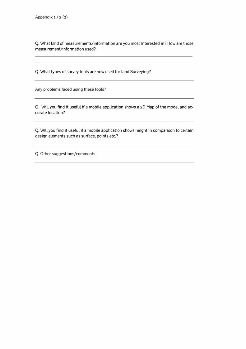
Appendix 1 / 2 (2)
Q. What kind of measurements/information are you most interested in? How are those measurement/information used? ______________________________________________________________________________ Q. What types of survey tools are now used for land Surveying?
Any problems faced using these tools?
Q. Will you find it useful if a mobile application shows a 2D Map of the model and ac-curate location?
Q. Will you find it useful if a mobile application shows height in comparison to certain design elements such as surface, points etc.?
Q. Other suggestions/comments


ISSN-L 1798-6656
ISSN 1798-6664
ISBN 978-952-317-131-2
www.liikennevirasto.fi