bileaflet, tilting disc and porcine aortic valve ... current clinical use, especially in the small...
TRANSCRIPT

JACC Vol. 3, NO.2February 1984:313-20
Bileaflet, Tilting Disc and Porcine Aortic Valve Substitutes: In VitroHydrodynamic Characteristics
313
AJIT P. YOGANATHAN, PhD,* AURELIO CHAUX, MD, FACe,t RICHARD J. GRAY, MD, FACe,t
YI-REN WOO, MS,* MICHELE DeROBERTIS, RN,t FRANK P. WILLIAMS, MS,*
JACK M. MATLOFF, MD, FACCt
Atlanta. Georgia and Los Angeles, California
The desire for a low profile mechanical valve with betterfluid dynamic performance led to the design and development ofthe St. Jude Medical bileaflet prosthesis. Comparative in vitro flow studies indicate that it has betterpressure drop characteristics than the Bjork-Shiley (convexo-concave) and Carpentier-Edwards porcine valvesin current clinical use, especially in the small sizes. Inthe 21 to 27 mm aortic valve size range the St. Judevalve has an average performance index of 0.66, compared with 0.46 and 0.32 for the Bjork-Shiley and Carpentier-Edwards valves, respectively. In contrast, theSt. Jude valve has larger regurgitant volumes than boththe Bjork-Shiley and Carpentier-Edwards valves.
Velocity measurements with a laser-Doppler ane-
Cardiac valve substitutes have been in clinical use for 25years (1-5). There are more than 50 speci fic types of such
devices but they can essentially be classified into six genericdesigns. These include individual leaflets (2-5), caged-ballvalves (3,4), caged-disc valves (6-8), hinged (or tilting)disc valves, bileaflet valves (9-11) and tissue valves (12-14).
Clinical experience with all of these valve substitutes hasindicated that there are well defined clinical sequelae thatmust be recognized when choosing a prosthesis ( 15). Theseinclude imperfect hemodynamic (hydraulic) performance,thromboembolism or in situ thrombosis, or both, limiteddurability, damage to the formed elements of the blood andpatient incompatibility (15,16). Susceptibility to infection
From the Bio Fluid Dynamics Laboratory, School of Chemical Engineering, Georgia tnstitute of Technology, Atlanta, Georgia,* and the Department of Thoracic and Cardiovascular Surgery, Cedars-Sinai MedicalCenter, Los Angeles, California." Manuscript received April 22, 1983:revised manuscript received July 18. 1983. accepted September 21. 1983.
Address for reprints: Richard Gray, MD. Department of Thoracic andCardiovascular Surgery. Cedars-Sinai Medical Center. X700 Beverly Boulevard. Los Angeles. California 90048.
iOI984 hy the Arn.vican College of Cardiology
mometer indicate relatively centralized flow with smallamounts ofturbulence downstream ofthe St. Jude valve.The flow is unevenly distributed between the central andside orifices. The turbulent shear stresses are, however,large enough to cause sublethal or lethal damage to bloodelements. Wall shear stresses are smaller than those measured downstream of the Bjork-Shiley valve. Regions offlow separation were observed just downstream from thesewing ring, which could lead to excess tissue growthalong the sewing ring.
The results of this study indicate that overall in vitrofluid dynamic performance of the St. Jude valve is superior to that of the two other commonly used prostheses.
and parabasilar insufficiency have also been defined asadverse consequences, unrelated to specific designcharacteristics.
Although the clinical results of valve replacement withcurrently available prostheses are satisfactory, imperfecthemodynamic performance has been a significant problem,especially when one considers the influence of hydraulicdesign on turbulence and stasis and their possible contribution to thromboembolism and hemolysis. In general,hemodynamic limitations occur in direct relation to valvesize. particularly in the aortic position (17,18). Thus, if oneis to precisely define the in vitro hydraulic performance ofa cardiac valve substitute before clinical trial, so as to minimize the chances for experiencing such clinical hemodynamic liability, then the aortic position would appear to bea very appropriate model.
To this end a flow apparatus, incorporating a laser-Doppler anemometer, has been designed to simulate certainfeatures of the human aortic root. Using this in vitro modeland companion in vivo clinical studies, a comprehensiveanalysis of the function of aortic valve substitutes can beachieved.
0735-1097!84/$3.00
314 YOGANATHAN ET AL.IN VITRO HYDRODYNAMIC ST. JUDE FUNCTION
JACe Vol. 3. No.2February 1984:313-20
It is the purpose of this report to describe in vitro studiesof the three most recent generic valve designs for aorticvalve replacement, the hinged (or tilting) disc, the bileafletvalve and tissue prostheses. The specific valves studied arethe Bjork-Shiley convexo-concave (model C-C), the St. JudeMedical bileaflet prosthesis and the Carpentier-Edwardsporcine valve (model 2625).
MethodsEquipment. The flow apparatus consists of an immer
sible centrifugal pump (Little Giant, Corp., OklahomaCity,Oklahoma), inflow section, flow channel, flow chamber,rotameter (Brooks 10-1110, Brooks Instruments, Hatfield,Pennsylvania) and a needle valve. Details of design, materials and fabrication of the three valves evaluated herehave been presented elsewhere (19-21).
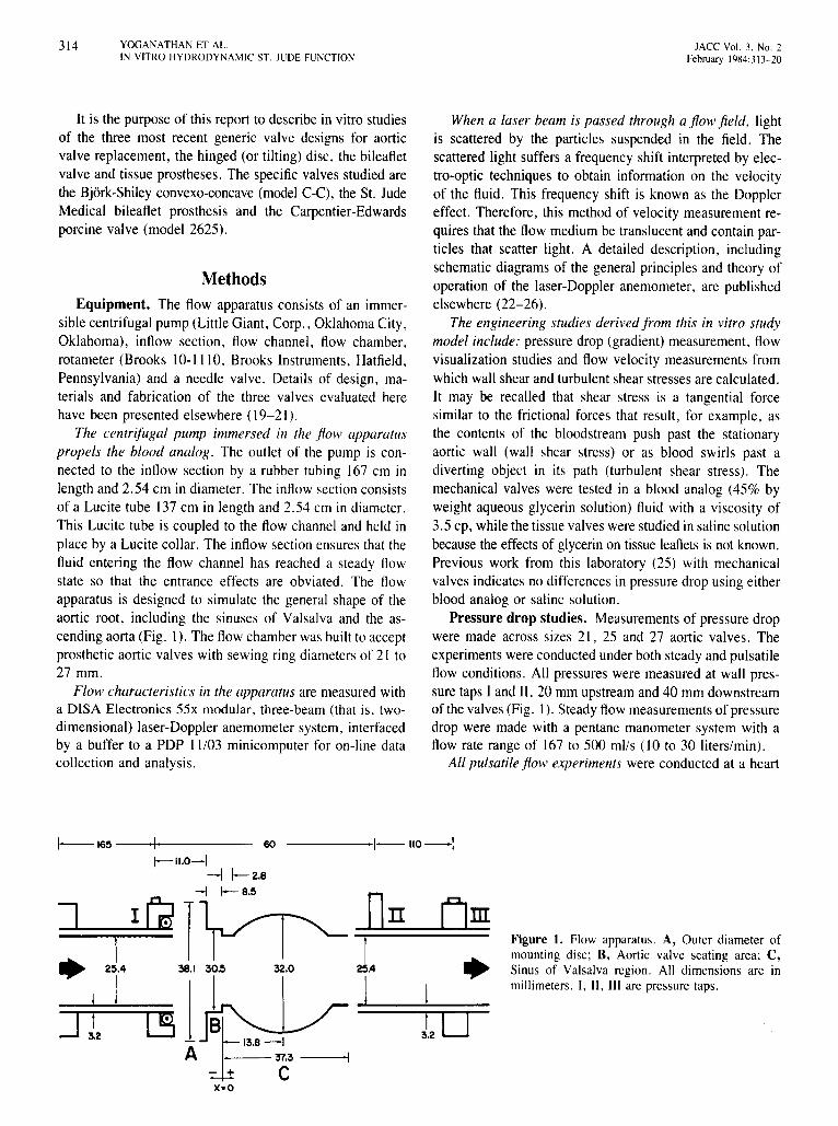
The centrifugal pump immersed in the flow apparatuspropels the blood analog. The outlet of the pump is connected to the inflow section by a rubber tubing 167 cm inlength and 2.54 em in diameter. The inflow section consistsof a Lucite tube 137cm in length and 2.54 cm in diameter.This Lucite tube is coupled to the flow channel and held inplace by a Lucite collar. The inflowsection ensures that thefluid entering the flow channel has reached a steady flowstate so that the entrance effects are obviated. The flowapparatus is designed to simulate the general shape of theaortic root, including the sinuses of Valsalva and the ascending aorta (Fig. I). The flow chamber was built to acceptprosthetic aortic valves with sewing ring diametersof 21 to27 mm.
Flow characteristics in the apparatus are measured witha DISA Electronics 55x modular, three-beam (that is, twodimensional) laser-Doppler anemometer system, interfacedby a buffer to a PDP 11103 minicomputer for on-line datacollection and analysis.
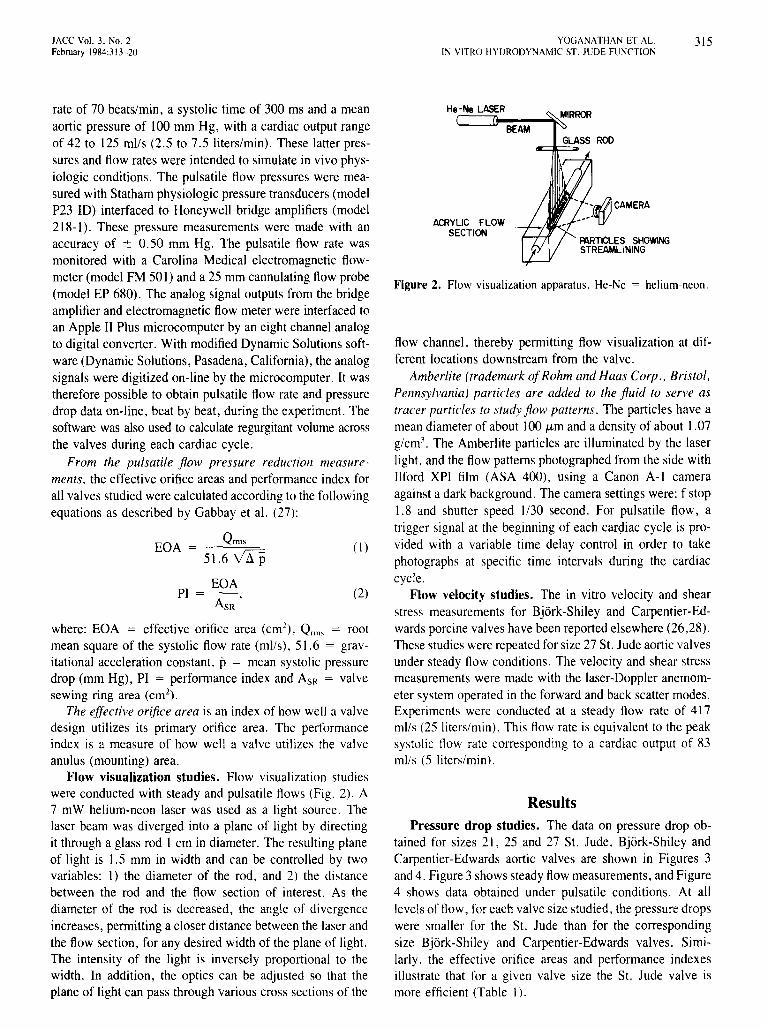
When a laser beam is passed through a flow field. lightis scattered by the particles suspended in the field. Thescattered light suffers a frequency shift interpreted by electro-optic techniques to obtain information on the velocityof the fluid. This frequency shift is known as the Dopplereffect. Therefore, this method of velocity measurement requires that the flow medium be translucent and contain particles that scatter light. A detailed description, includingschematic diagrams of the general principles and theory ofoperation of the laser-Doppler anemometer, are publishedelsewhere (22-26).
The engineering studies derived from this in vitro studymodel include: pressure drop (gradient) measurement, flowvisualization studies and flow velocity measurements fromwhichwall shear and turbulentshear stresses are calculated.It may be recalled that shear stress is a tangential forcesimilar to the frictional forces that result, for example, asthe contents of the bloodstream push past the stationaryaortic wall (wall shear stress) or as blood swirls past adiverting object in its path (turbulent shear stress). Themechanical valves were tested in a blood analog (45% byweight aqueous glycerin solution) fluid with a viscosity of3.5 cp, while the tissuevalveswerestudiedin salinesolutionbecause the effects of glycerin on tissue leaflets is not known.Previous work from this laboratory (25) with mechanicalvalves indicates no differences in pressuredrop using eitherblood analog or saline solution.
Pressure drop studies. Measurements of pressure dropwere made across sizes 21, 25 and 27 aortic valves. Theexperiments wereconducted under both steady and pulsatileflow conditions. All pressures were measured at wall pressure taps I and II, 20 mm upstream and 40 mm downstreamof the valves(Fig. I). Steadyflow measurements of pressuredrop were made with a pentane manometer system with aflow rate range of 167 to 500 mils (l0 to 30 liters/min).
All pulsatile flow experiments were conducted at a heart
Figure 1. Flow apparatus. A, Outer diameter ofmounting disc; B, Aortic valve seating area; C,Sinus of Valsalva region. All dimensions are inmillimeters. I, II, III are pressure taps.
-----1-110--1
A
1-165 1 60
1--".0-1-I 1-2.8
~1-l1-8'5
1• 25.4 38.1 32.0
11~
JACC Vol. 3, No, 2February 1984:313-20
YOGANATHAN ET AL.IN VITRO HYDRODYNAMIC ST, JUDE FUNCTION
315
where: EGA = effective orifice area (ern"), Qrms = rootmean square of the systolic flow rate (mils), 51.6 = gravitational acceleration constant, p = mean systolic pressuredrop (mm Hg), PI = performance index and ASR = valvesewing ring area (em"),
The effective orifice area is an index of how well a valvedesign utilizes its primary orifice area. The performanceindex is a measure of how well a valve utilizes the valveanulus (mounting) area.
Flow visualization studies. Flow visualization studieswere conducted with steady and pulsatile flows (Fig. 2), A7 mW helium-neon laser was used as a light source. Thelaser beam was diverged into a plane of light by directingit through a glass rod I ern in diameter. The resulting planeof light is 1.5 mm in width and can be controlled by twovariables: I) the diameter of the rod, and 2) the distancebetween the rod and the flow section of interest. As thediameter of the rod is decreased, the angle of divergenceincreases, permitting a closer distance between the laser andthe flow section, for any desired width of the plane of light.The intensity of the light is inversely proportional to thewidth. In addition, the optics can be adjusted so that theplane of light can pass through various cross sections of the
~Jr@CAMERA
PARTICLES SHOWINGSTREAMLINING
BEAM
He-Ne LASER
ACRYLIC FLOWSECTION
ResultsPressure drop studies. The data on pressure drop ob
tained for sizes 21,25 and 27 St. Jude, Bjork-Shiley andCarpentier-Edwards aortic valves are shown in Figures 3and 4. Figure 3 shows steady flowmeasurements, and Figure4 shows data obtained under pulsatile conditions. At alllevelsof flow, for each valve size studied, the pressure dropswere smaller for the 51. Jude than for the correspondingsize Bjork-Shiley and Carpentier-Edwards valves. Similarly, the effective orifice areas and performance indexesillustrate that for a given valve size the St. Jude valve ismore efficient (Table I).
Figure 2. Flow visualization apparatus. He-Ne = helium-neon.
flow channel, thereby permitting flow visualization at different locations downstream from the valve.
Amberlite (trademark ofRohm and Haas Corp., Bristol,Pennsylvania) particles are added to the fluid to serve astracer particles to study flow patterns. The particles have amean diameter of about 100 urn and a density of about 1.07g/crrr'. The Amberlite particles are illuminated by the laserlight, and the flow patterns photographed from the side withIlford XPI film (ASA 400), using a Canon A-I cameraagainst a dark background. The camera settings were: f stopI. 8 and shutter speed 1/30 second. For pulsatile flow, atrigger signal at the beginning of each cardiac cycle is provided with a variable time delay control in order to takephotographs at specific time intervals during the cardiaccycle.
Flow velocity studies. The in vitro velocity and shearstress measurements for Bjork-Shiley and Carpentier-Edwards porcine valves have been reported elsewhere (26,28).These studies were repeated for size 27 St. Jude aortic valvesunder steady flow conditions. The velocity and shear stressmeasurements were made with the laser-Doppler anemometer system operated in the forward and back scatter modes.Experiments were conducted at a steady flow rate of 417mils (25 liters/min). This flow rate is equivalent to the peaksystolic flow rate corresponding to a cardiac output of 83mils (5 liters/min),
(I)
(2)EGA
PI = AsR '
rate of 70 beats/min, a systolic time of 300 ms and a meanaortic pressure of 100 mm Hg, with a cardiac output rangeof 42 to 125 mils (2.5 to 7,5 liters/min). These latter pressures and flow rates were intended to simulate in vivo physiologic conditions. The pulsatile flow pressures were measured with Statham physiologic pressure transducers (modelP23 10) interfaced to Honeywell bridge amplifiers (model218-1), These pressure measurements were made with anaccuracy of ± 0.50 mm Hg. The pulsatile flow rate wasmonitored with a Carolina Medical electromagnetic flowmeter (model FM 50l) and a 25 mm cannulating flow probe(model EP 680). The analog signal outputs from the bridgeamplifier and electromagnetic flow meter were interfaced toan Apple II Plus microcomputer by an eight channel analogto digital converter. With modified Dynamic Solutions software (Dynamic Solutions, Pasadena, California), the analogsignals were digitized on-line by the microcomputer. It wastherefore possible to obtain pulsatile flow rate and pressuredrop data on-line, beat by beat, during the experiment. Thesoftware was also used to calculate regurgitant volume acrossthe valves during each cardiac cycle.
From the pulsatile flow pressure reduction measurements, the effective orifice areas and performance index forall valves studied were calculated according to the followingequations as described by Gabbay et al. (27):
EGA = Qrms51.6 VLfP

316 YOGANATHAN ET AL.IN VITRO HYDRODYNAMIC ST. JUDE FUNCTION
JACC Vol. 3, No.2February 1984:313-20
28
I.- ST. JUDE 0
I
26 0-- BJORK-SHILEY II No 21
IJ22
II
C; //,:I:e 18.§
~ 14 '1° dO.I I /0I /.
LlJll:: I p/~
10 I • I
~ 9 ILlJ '!fll:: , I Ic, 1 00
6 I / , No.27I·V ,0"1~0 ->Q / • sr:
2 /~/.o" .>.6~ , ....._____e
0 100 200 300 400 500STEADY FLOW (mils)
Figure3. Pressure drop measurements obtained at varying levelsof steady flow. St. Jude and Bjork-Shiley aortic prostheses, sizes21, 25 and 27, are compared.
Regurgitant flow. The regurgitant characteristics(obligatoryclosure volumeplus leakage volume)of the threevalve designs at a heart rate of 70 beats/min and cardiacoutput of 42 to 125 mils (2.5 to 7.5 liters/min) are shownin Table 2. Within the experimental error (± I ml/beat),there was no variation in the absolute regurgitant volumefor a given valve design as the cardiac output was variedat 70 beats/min. This is in agreement with the observationsmade by Dellsperger et al. (29). Varying directly with valvesize, regurgitation in the St. Jude aortic valve is 2.1 to 2.5
mllbeat more than for the corresponding size Bjork-Shileyvalve and from 6.8 to 9.7 mllbeat more than with the Carpentier-Edwards valve at a heart rate of 70 beats/min.
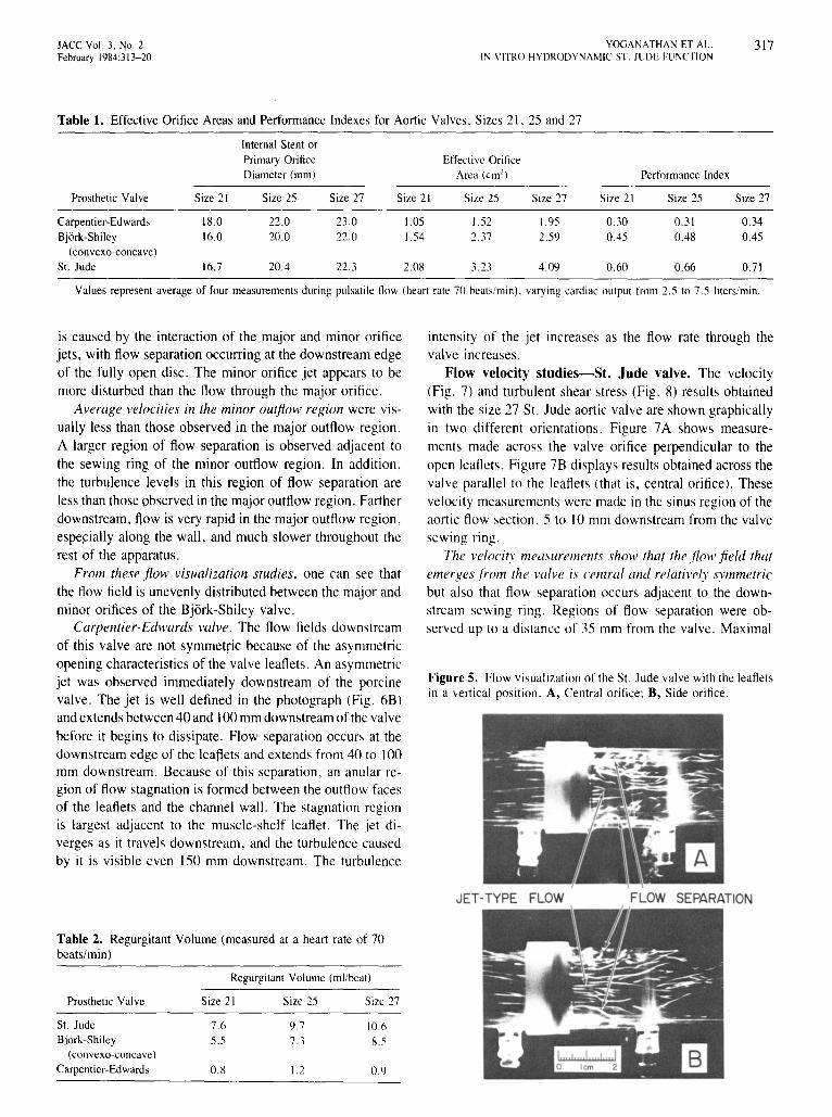
Flow visualization studies. Examples of the flow visualization studies are shown in Figures 5 and 6. St. Judevalve. The photographs shown in Figure 5 were taken withthe leaflets in the vertical position, and the thin sheet oflaser light is parallel to the plane of the flow section. Itshows that the flow through the central and side orifices ofthe St. Jude aortic valve is jet-like.
The photograph of the central orifice (Fig. 5A) showsflow separation occurring adjacent to the sewing ring. Thisphenomenon, at its maximum, occupies one-third to onehalf of the flow channel cross section along the orifice ofthe valve. The region of flow separation reattaches to thewall approximately 40 mm downstream of the valve.
In the side orifice region, Figure 5B also shows flowseparation. However, reattachment occurs closer to the valve,about 30 mm downstream. The degree of separation in theregion of the side orifices is smaller than that occurring inthe central orifice, indicating that more fluid flows throughthe side orifices. Vorticesand reverse flow along the channelwall are observed in all flow separation regions.
Bjork-Shiley valve. Because the occluder of the BjorkShileyprosthesispivotsoff center, there are two asymmetricorifices in the open position. In Figure 6A, the disc is seenfrom the side. The larger, or major orifice is above the disc.The flow through the major orifice is jet-like. The jet slantsfrom left to right and impinges on the flow channel wallbetween 20 and 40 mm downstream from the valve. Flowseparation is observed above the major orifice jet, adjacentto the sewing ring in that region. Stagnation is observed inthe immediate vicinity of the aortic face of the disc. This
No. 21
Figure4. Pressure drop measurements obtained at varyinglevels of pulsatile flow. St. Jude, Bjork-Shiley and Carpentier-Edwards aortic prostheses, sizes 21, 25 and 27, arecompared.
30
18
34
38_._. PORCINE- BJORK - SHILEY---S1. JUDE
o 100 200 300 400 0 100 200 300 400PULSATILE SYSTOLIC FLOW
ROOT MEAN SQUAREQRMS,mils
Iiiiiiiiiiiiiitiiiii!
o 100 200 300 400
34
38
JACC Vol. 3, No.2February 1984:313-20
YOGANATHAN ET AL.IN VITRO HYDRODYNAMIC ST. JUDE FUNCTION
317
Table 1. Effective Orifice Areas and Performance Indexes for Aortic Valves, Sizes 21,25 and 27
Internal Stent orPrimary Orifice Effectivc OrificeDiameter (0101) Area (crrr') Performance Index
Prosthetic Valve Size 21 Size 25 Size 27 Size 21 Size 25 Size 27 Size 21 Size 25 Size 27
Carpentier-Edwards 18.0 22.0 23.0 1.05 1.52 1.95 0.30 0.31 0.34Bjork-Shiley 16.0 20.0 22.0 1.54 2.37 2.59 0.45 0.48 0.45
(convexo-concavc)
St. Jude 16.7 20.4 22.3 2.08 3.23 4.09 0.60 0.66 0.7\
Values represent average of four measurements during pulsatile flow (heart rate 70 beats/min). varying cardiac output from 2.5 to7.5 liters/min.
is caused by the interaction of the major and minor orificejets, with flow separation occurring at the downstream edgeof the fully open disc. The minor orifice jet appears to bemore disturbed than the flow through the major orifice.
Average velocities in the minor outflow region were visually less than those observed in the major outflow region.A larger region of flow separation is observed adjacent tothe sewing ring of the minor outflow region. In addition,the turbulence levels in this region of flow separation areless than those observed in the major outflow region. Fartherdownstream, flow is very rapid in the major outflow region,especially along the wall, and much slower throughout therest of the apparatus.
From these flow visualization studies, one can see thatthe flow field is unevenly distributed between the major andminor orifices of the Bjork-Shiley valve.
Carpentier-Edwards valve. The flow fields downstreamof this valve are not symmetric because of the asymmetricopening characteristics of the valve leaflets. An asymmetricjet was observed immediately downstream of the porcinevalve. The jet is well defined in the photograph (Fig. 6B)andextends between40 and 100mm downstreamof the valvebefore it begins to dissipate. Flow separation occurs at thedownstream edge of the leaftets and extends from 40 to 100mm downstream. Because of this separation, an anular region of flow stagnation is formed between the outflow facesof the leaflets and the channel wall. The stagnation regionis largest adjacent to the muscle-shelf leaflet. The jet diverges as it travels downstream, and the turbulence causedby it is visible even 150 mm downstream. The turbulence
intensity of the jet increases as the flow rate through thevalve increases.
Flow velocity studies-St. Jude valve. The velocity(Fig. 7) and turbulent shear stress (Fig. 8) results obtainedwith the size 27 St. Jude aortic valve are shown graphicallyin two different orientations. Figure 7A shows measurements made across the valve orifice perpendicular to theopen leaflets. Figure 7B displays results obtained across thevalve parallel to the leaflets (that is, central orifice). Thesevelocity measurements were made in the sinus region of theaortic flow section,S to 10 mm downstream from the valvesewing nng.
The velocity measurements show that the flow .field thatemerges from the valve is central and relatively symmetricbut also that flow separation occurs adjacent to the downstream sewing ring. Regions of flow separation were observed up to a distance of 35 mm from the valve. Maximal
Figure5. Flow visualization of theSt. Jude valve with theleafletsin a vertical position. A, Central orifice; B, Side orifice.
JET·TYPE FLOW FLOW SEPARATION
Table 2. Regurgitant Volume (measured at a heart rate of 70beats/min)
Regurgitant Volume (mllbeat)
Prosthetic Valve Size 21 Size 25 Size 27
St. Jude 7.6 9.7 10.6Bjork-Shiley 5.5 7.3 8.5
(convexo-concavc)
Carpentier-Edwards 0.8 1.2 0.9
318 YOGANATHAN ET AL.IN VITRO HYDRODYNAMIC ST. JUDE FUNCTION
JACC Vol. 3. No.2February 1984:313-20
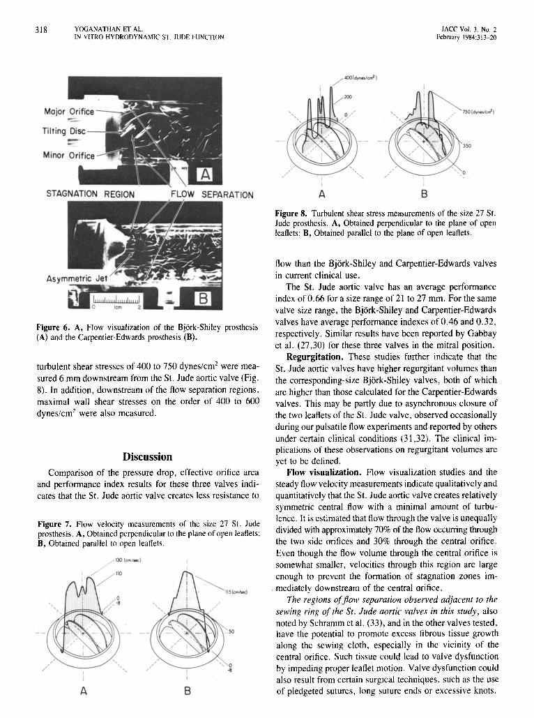
STAGNATION REGION FLOW SEPARATION A B
Figure 6. A, Flow visualization of the Bjork-Shiley prosthesis(A) and the Carpentier-Edwards prosthesis (B).
Figure 7. Flow velocity measurements of the size 27 SI. Judeprosthesis. A, Obtained perpendicular to the plane of open leaflets:B, Obtained parallel to open leaflets.
Figure 8. Turbulent shear stress measurements of the size 27 SI.Jude prosthesis. A, Obtained perpendicular to the plane of openleaflets: B, Obtained parallel to the plane of open leaflets.
flow than the Bjork-Shiley and Carpentier-Edwards valvesin current clinical use.
The SI. Jude aortic valve has an average performanceindex of 0.66 for a size rangeof 21 to 27 mm. For the samevalve size range, the Bjork-Shiley and Carpentier-Edwardsvalves have averageperformance indexesof 0.46 and 0.32,respectively. Similar results have been reported by Gabbayet al. (27,30) for these three valves in the mitral position.
Regurgitation. These studies further indicate that the51. Jude aortic valves have higher regurgitant volumes thanthe corresponding-size Bjork-Shiley valves, both of whichare higher than those calculated for the Carpentier-Edwardsvalves. This may be partly due to asynchronous closure ofthe two leaflets of the SI. Jude valve, observed occasionallyduringour pulsatile flow experiments and reportedby othersunder certain clinical conditions (31,32). The clinical implications of these observations on regurgitant volumes areyet to be defined.
Flow visualization. Flow visualization studies and thesteady flow velocitymeasurements indicatequalitativelyandquantitatively that the SI. Jude aortic valve creates relativelysymmetric central flow with a minimal amount of turbulence. It is estimatedthat flow throughthe valve is unequallydivided with approximately 70% of the flow occurring throughthe two side orifices and 30% through the central orifice.Even though the flow volume through the central orifice issomewhat smaller, velocities through this region are largeenough to prevent the formation of stagnation zones im-
. mediately downstream of the central orifice.The regions offlow separation observed adjacent to the
sewing ring of the St . Jude aortic valves in this study , alsonoted by Schramm et al. (33), and in the other valves tested,have the potential to promote excess fibrous tissue growthalong the sewing cloth, especially in the vicinity of thecentral orifice. Such tissue could lead to valve dysfunctionby impeding proper leaflet motion. Valvedysfunctioncouldalso result from certain surgical techniques, such as the useof pledgeted sutures, long suture ends or excessive knots.BA
Discussion
Comparison of the pressure drop. effective orifice areaand performance index results for these three valves indicates that the SI. Jude aortic valve creates less resistance to
turbulent shear stresses of 400 to 750 dynes/em" were measured 6 mm downstream from the 51. Jude aortic valve(Fig.8). In addition, downstream of the flow separation regions,maximal wall shear stresses on the order of 400 to 600dynes/em? were also measured.
JACC Vol. 3. No.2February 1984:313-20
YOGJ\NATHAN ET J\L.IN VITRO HYDRODYNAMIC ST JUDE FUNCTION
319
During the 4 years of in vivo clinical use, only one caseof leaflet sticking has been reported (34). In our own experience of 300 valve replacements, we have recently seenone case in which the leaflets were stuck in a semi-openposition after aortic valve replacement in a patient who hadan oversized valve and whose anticoagulation was poorlycontrolled. In the mitral position, this problem may be moreevident in patients who are not receiving anticoagulant therapy and experience minute thrombi causing impaired leafletmobility (35). Because leaflet motion is a critical concern,it is of the utmost importance that movement of the leafletscan be monitored either by echocardiography orcinefluorscopy.
Shear stress. The velocity and shear fields created bythe St. Jude aortic valve are different from those reportedfor the Bjork-Shiley and porcine valves (26,28). In previouswork by one of us (26,28) and others (36,37), the BjorkShiley and Carpentier-Edwards valves were associated withmuch larger turbulent shear stresses from I ,000 to 3,000dynes/em", The wall shear stresses downstream of the St.Jude valve are lower than those observed with the BjorkShiley valve and other mechanical valves studied previously(38).
Turbulent shear stresses of 400 to 750 dynes/ern" occurring in vivo may still be sufficient to cause sublethal orlethal damage to blood elements, such as red cells andplatelets. Whether such damage to the blood elements andthe endothelial lining of the vessel wall can lead to mildhemolysis and thromboembolic complications is yet to bedetermined. To date, neitherof these complicationshas beena serious problem in clinical practice.
Conclusion. We conclude, on the basis of these in vitrofluid dynamic analyses, that overall, the bileaflet St. Judeaortic valve prosthesis performs in a manner superior toBjork-Shiley convexo-concave tilting disc and CarpentierEdwards tissue valves. However, these studies cannot indicate whether the in vitro characteristics of reduced shearstress and turbulence will translate to increased valve durability or lessened thromboembolism.
ReferencesI. Hufnagel CA. Harvey WP. Rabil PL McDermott TE. Surgical cor
rection of aortic insufficiency. Surgery 1954:35:673-83.
2. Bahnson HT. Spencer FC, Busse EFG. Davis FW Jr. Cusp replacement and coronary artery perfusion in open operations on the aorticvalve. Ann Surg 1960;152:494-501.
3. Harken DE. Soroff HS. Taylor Wl. Lefemine AA. Gupta KS. LunzerS. Partial and complete prostheses in aortic insufficiency. J ThoracCardiovasc Surg 1960;40:744-62.
4. Starr A, Edwards ML. Mitral replacement: clinical experience with aball-valve prosthesis. Ann Surg 1961:154:726-40.
5. McGoonDC, MankinHT, KirklinJW. Resultsof open-heart operation
for acquired aortic valve disease. J Thorac Cardiovasc Surg1963;45:47-66.
6. Harken DE, Matloff JM. Zuckerman W. Chaux A. A new mitralvalve. J Thorac Cardiovasc Surg 1968;55:369-82.
7. Beall AC Jr. Bloodwell RD. Liotta D. Cooley DA. DeBakey ME.Clinical experience with a Dacron velour-covered Teflon-disc mitralvalve prosthesis. Ann Thorac Surg 1968;5:402-10.
8. Kay EB. Suzuki A. Demaney M. Zimmerman HA. Comparison ofball and disc valves for mitral valve replacement. Am J Cardiol1966;18:504-14.
9. Bjork YO. The history of the Bjork-Shiley tilting disc valve. MedInstrum 1977:11:80-4.
10. Lillehei CWo Kaster RL. Bloch JH. New central flow pivoting discaortic and mitral prosthesis. Clinical experience. NY State J Med1972;72:1738.
II. Nicoloff DM. Emery RW. Arom KY, et al. Clinical hemodynamicresults with the St. Jude medical cardiac valve prostheses. A threeyear experience. J Thorac Cardiovasc Surg 1981 :82:674-83.
12. Carpentier A. Dcloche A. Reiland 1, et al. Six year follow-up ofglutaraldehyde-preserved heterografts. With particular reference totreatment of congenital valve malformations. J Thorac CardiovascSurg 1974:68:771-82.
13. Cohn LH. Lambert Jl. Castaneda AR. Collins J1. Cardiac valve replacement with the stabilized glutaraldehyde porcine aortic valve: indications. operative results. and follow-up. Chest 1975;68:162-5.
14. Stinson EB. Griepp RB. Shumway NE. Clinical experience with porcine aortic valve xcnogratts for mitral valve replacement. Ann ThoracSurg 1974:18:391-40 I.
15. Marlotf JM. Chaux A. What is the current status of prosthetic valvereplacement" In: Brest AN. ed. CardiovascularClinics. Controversiesin Cardiology. Yol. I. Philadelphia: FA Davis, 1977:241-68.
16. Byrne JP. Behrendt DM. Kirsh MM. Orringer MB. Replacement ofheart valves by prosthetic devices. Pathobiology 1977:7:83-114.
17. Hehrlcin FW. Gottwik M. Fraedrich G, Mulch 1. First clinical experience with a new all-pryolytic carbon bileatlet heart valve prosthesis. J Thorac Cardiovasc Surg 1980;79:632-6.
18. Chaux A. Gray RJ. Matloff JM, Feldman H. Sustaita H. An appreciation of the new St. Jude valvular prosthesis. J Thorac CardiovascSurg 1981 :81:202-11.
19. Bjork YO. The improved Bjork-Shiley tilting disc valve prosthesis.Scand J Thorac Cardiovasc Surg 1978:12:81-4.
20. Carpentier A. From xenograft valve to valvular xenobioprosthesis. In:Scbening R. Klovekom WP. Meisner H. Struck E. eds. BioprostheticCardiac Valves. Munich: Deutsches Herzzenrum Munchen, 1979:1-15.
21. Emery RW. Palmquist WE. Metther E. Nicoloff DM. A new cardiacvalve prosthesis: in vitro results. Trans Am Soc Artif Intern Organs1978:24:550-6.
22. Yoganathan AP. Cardiovascular Fluid Dynamics. Pasadena:CaliforniaInstitute of Technology. 1978. Thesis.
23. Yoganathan AP. Reamer HH. Corcoran WHo Harrison EC. LaserDoppler anemometer to study velocity fields in the vicinity of prosthetic heart valves. Med Bioi Eng Comput 1979;17:38-44.
24. Yoganathan AP. Corcoran WHo Harrison EC. In vitro velocity measurements in the vicinity of aortic prostheses. J Biomechanics1979:12:135-52.
25. Yoganathan AP. Corcoran WH, Harrison EC. Pressure drops acrossprosthetic aortic heart valves under steady and pulsatile flow-in vitromeasurements. J Biomechanics 1979;12:153-64.
20. Yoganathan AP. Corcoran WHo Harrison EC, Carl JR. The BjorkShiley aortic prosthesis: flow characteristics. thrombus formation andtissue overgrowth. Circulation 1978:5X:70-0.
27. Gabbay S. McQueen DM. Yellin EL. Frater RWM. In vitro hydrodynamic comparison of mitral valve bioprostheses. Circulation1979:00(suppll):1-62-70.
320 YOGANATHAN ET AL.IN VITRO HYDRODYNAMIC ST. JUDE FUNCTION
lACC Vol. 3. No.2February 1984:313- 20
28. Yoganathan AP, Corcoran WHoHarrison EC. Chaux A. In vitro fluiddynamics of the St. Jude. lonescu-Shiley and Carpentier-Edwardsaortic heart valve prostheses. In: Schneck OJ, ed. Bio Fluid Mechanics. Vol. 2. New York: Plenum. 1980:295-316.
29. Dellsperger KC. Wieting OW. Baehr DA. Band RJ, Brugger JP,Harrison EC. Regurgitation characteristics of prosthetic valves: dependence on heart rateandcardiac output. AmJ Cardiol 1983:51:321- 8.
30. Gabbay S. Yellin EL. Frishman WHo Frater RWM. In vitro hydrodynamic comparison of St. Jude. Bjork-Shiley and Hall-Kaster valves.Trans Am Soc Artif Intern Organs 1980:26:231- 6 .
31. Rainer WG. Letters to theeditor. J Thorac Cardiovasc Surg 1981:82:462.
32. Feldman H. Gray R. Chaux A. et al, Noninvasive in vivo and in vitrostudy of the St. Jude mitral valve. Am J Cardiol 1982;49:1101-9.
33. Schramm D. BaldaufW, Meisner H. Flow pattern and velocity fielddistal to human aortic and artificial heart valves as measured simultaneously by ultramicroscope anemometry in cylindrical glass tubes.J Thorac Cardiovasc Surg 1980;28:133-40.
34. Ziemer G. Luhmer I, Oelert H, Borst H. Malfunction of a St. Judevalve in mitral position. Ann Thorac Surg 1982;33:391-5.
35. Nunez L. Iglesias A. Sotillo J. Entrapment of leaflet of St. Judemedical cardiac valve prosthesis by miniscule thrombus. Report oftwo cases. Ann Thorac Surg 1980:29:567-9.
36. Figliola RS. In vitro velocity and stress measurements in the vicinityof prosthetic heartvalves using laser-Doppler and hotfilrn anernometry.South Bend. Indiana: University of Notre Dame. 1979. Thesis.
37. Phillips WM, Snyder A. Alchas P. Rosenberg G. Pierce WS. Pulsatileprosthetic valve flows, Trans Am SocArtif Intern Organs 1980;26:43- 9.
38. YozanathanAP. Corcoran WHoHarrison EC. Wall shear stress measurernents in the near vicinity of prosthetic aortic heart valves. JBioengineering 1978:2:369- 79.