big sandy plant, unit 2 wfgd project phase i report ...psc.ky.gov/pscscf/2011...
TRANSCRIPT

PARSONS EgC
Big Sandy Plant,
Unit 2
WFGD Project
PHASE I REPORT
Engineering Services
Report No. AEBS-2-LI-0 12-000 1, Rev. 0
presented to
December 30,2004
KPSC Case No. 2011-00401Sierra Club First Set of Data Requests
Dated January 13, 2012Item No. 27(a)Attachment 1
Page 1 of 113

PARSONS EaC
able of Contents >
. . ... ........ - ...
Page
Section 1
Section 2
Section 3
Section 4
Section 5
Executive Summary ..................................................................... 1-1
....................................................................... Study Description -2-1
.................................................... 2.1 Characteristics of Existing Unit 2-1
............................................. 2.2 Proposed Sulfur Emissions Control 2 - 1
.............................................................................. 2.3 Scope of Work 2 - 1
.................................................................................. 2.4 Deliverables 2 - 2
.............................................................. Conceptual Design Basis 3-1 .. .
................................................................................... 3.1 Introduction 3 - 1
.......................................................... 3.2 As-Fired Coal Composition 3 - 1
3.3 Ambient Conditions ...................................................................... 3-3
......................................................................... 3.4 Coal Composition 3 - 3 . . ................................................................ 3.5 Limestone Composihon 3 - 4
........................................................................... 3.6 WFGD Absorber 3 - 4
3.7 Dewatering ..................................................................................... 3-5
....................................................................................... 3.8 Electrical 3 - 6
............................................................................ 3.9 Control Systems 3 - 6
.................................................. Description of Conceptual Design 4-1
.............................. 4.1 Process Flow Diagrams and Material Balance 4-1
................................................................. 4.2 Process Equipment List 4-3
.................................................... 4.3 Conceptual Electric Load List 4 - 4
...................................... 4.4 Conceptual Electrical One Line diagram 4-4
Conceptual Plot Plans and General Arrangement Drawings ............... 5-1
5.1 Summary ........................................................................................ 5-1
............................................................... 5.2 Recommended Plot Plan 5 - 1
..................................................... 5.3 Plot Plan Development Criteria 5-2
................................................................... 5.4 General Arrangements 5-3
5.5 Stack Location ............................................................................... 5-4
5.6 Big Sandy Unit 1 Layout Considerations ..................................... 5 - 4
KPSC Case No. 2011-00401Sierra Club First Set of Data Requests
Dated January 13, 2012Item No. 27(a)Attachment 1
Page 2 of 113

PARSONS EeC
Section 6
Section 7
Section 8
Appendix A
Appendix B
Appendix C
Appendix D
Page
.................................................................... Phase Ila Objectives 6-1
................................................................................... 6.1 Introduction 6 - 1
................................... 6.2 Major Issues to be Addressed in Phase IIa 6-2
Big Sandy Unit 1 Incremental Issues ................................................ 7-1
7.1 Incremental Issues with Adding WFGD to Big Sandy Unit 1 ...... 7-1
7.2 Incremental Issues with Adding SCR to Big Sandy Unit 1 .......... 7-2
7.3 Incremental Costs Associated with Adding Unit 1 ....................... 7-2
Summary of Phase 1 ........................................................................ 8-1
.............................................................................. 8.1 Schedule Basis 8 - 1
....................................................................... 8.2 Project Critical Path 8-2
................................................................... 8.3 Engineering Schedule 8 - 2
........................................................................... 8.4 Division of Work 8.3
Exhibit 8.1 . Schedule
Exhibit 8.2 . Division of Work
WFGD Material Balance Tables and Process Flow Diagrams
Plot Plans and General Arrangement Drawings
Process Equipment List
Conceptual Electrical One Line Diagram and Conceptual Electrical Load List
KPSC Case No. 2011-00401Sierra Club First Set of Data Requests
Dated January 13, 2012Item No. 27(a)Attachment 1
Page 3 of 113

PARSONS E&C
- - - . -- - - - .- -- - - j Executive Summary - -- - . - - .. . . - - - - - - - - -
Parsons E& C was chosen by the American Electric Power Services Corporation (AEPSC) to assist in their efforts to retrofit a Wet Flue Gas Desulfurization System at the Kentucky Power Company's Big Sandy Plant, Coal Fired Electric Generating Unit 2.
The overall project will consist of several different phases as defined below:
Phase I - Conceptual Engineering and Planning
Phase I1 - Scope Definition and Project Planning
Phase III - Project Execution
These are further defined in AEPSC's Specification PE-BS 12-TS-0001.
This report has been prepared at the conclusion of Phase I activity to document the work performed. The work elements developed comprise of the following:
Conceptual Plot Plans (various alternatives including recommended preliminary layout)
Conceptual System Descriptions
Conceptual General Arrangements
Conceptual Onelines
Conceptual Process Flow Diagrams and Material Balances
Proposal for Phase IIa (submitted separately)
Listing of Outstanding Issues and Studies to be resolved 1 performed during Phase Ha
Incremental issues associated with the addition of an SCR on Unit 1
Incremental issues associated with Unit 1 being added to the Unit 2 absorber (two units into one vessel).
Phase IIa Conceptual Schedule
Throughout this project, we will continuously review all decisions by measuring them based on their effects on safety, reliability, schedule, and cost.
KPSC Case No. 2011-00401Sierra Club First Set of Data Requests
Dated January 13, 2012Item No. 27(a)Attachment 1
Page 4 of 113

PARSONS EfiC
- - - - - - - - - - - . - - - - - - -- 1
Executive Summary . . - -. - - - - - . - - - - - - - - - - - . -
Since Parsons E&C is currently providing similar services for the Mitchell Plant WFGD System, the AEPSC and Parsons E&C Tier IT team has been capitalizing on the experience gained from that effort and will continue to build upon it. Many studies and evaluations were performed and we will build upon acquired knowledge as we move forward on this project. Where site-specific issues are concerned, these will be considered and tailored to the project.
In an effort to mitigate the risks that could potentially impede successful completion of the project, the AEPSC and Parsons E&C Tier II team has identified many actions that need to be addressed in the next Phase of the project. A complete listing of these major open issues is included in Section 6. These issues will be addressed during the early part of the next phase and be scheduled logically to sequence activities that ensure a complete, integrated plan as depicted below.
STUD1 ES AND EVALUATIONS
a a ENGINEERING & DEVELOPMENT
OF MATERIAL QUANTITIES a
ESTIMATE PLANT COST
a a
Following is a partial list of the major Phase IIa studies/evaluations to be completed:
Boiler upgrade engineering scope definition to be included in Parsons E&CYs scope of work
Determination of limestone delivery methodology to be implemented at the plant
Gypsum disposal options
Service water source determination and treatment method
rn System blowdown options and determination of proper treatment method(s)
Permitting support for various recent options related to dust generation from trucks and materials handling
KPSC Case No. 2011-00401Sierra Club First Set of Data Requests
Dated January 13, 2012Item No. 27(a)Attachment 1
Page 5 of 113

Fixing the stack location once an FGD OEM supplier is determined
Potential examination of applying an emissions control technology to Big Sandy Unit 1.
KPSC Case No. 2011-00401Sierra Club First Set of Data Requests
Dated January 13, 2012Item No. 27(a)Attachment 1
Page 6 of 113

PARSONS EfiC
. . . . . . . . . . . . . . . . . . . ...-....... -............... ... ......... . , . . ,
Study Description . . 1 .... L ........ ..........-... -- :- .. .. .I
2.1 Characteristics of Existing Unit
Big Sandy Unit #2 is a pulverized coal wall fired unit with a dry bottom pressurized boiler. The nominal unit rating, prior to FGD conversion, is 865 MW gross and 800 MW net. The full load firing rate is 8,180 MM B t u h and the minimum load firing rate is 3,017 MM B t u h . The unit has a Ljungstrom Rotary Tri-Sector air heater, a cold electrostatic precipitator (ESP), and low NO, burners. Ignition fuel is #2 oil. The unit has been retrofitted with an SCR for additional NO, control. Booster fans were added as part of the SCR installation. It will be necessary to lower SO2 emissions to meet the requirements of the AEPSC Fleet SO2 Compliance Plan.
2.2 Pro~osed Sulfur Emissions Control
The proposed method to lower SO2 emissions at Big Sandy Unit #2 is to retrofit a Wet Flue Gas Desulfurization (WFGD) system that will allow burning of Northern Appalachian Basin or Illinois Basin high sulfur coals with a sulfur content of up to 4.5 lb S02/MM Btu. The WFGD system will be designed to have an SO2 removal efficiency of 98% and will utilize 92% active calcium carbonate limestone to produce wallboard grade gypsum.
2.3 S c o ~ e of Work
The scope of work includes Phase I conceptual engineering and design for retrofit of a WFGD system at Big Sandy Unit # 2 as part of the AEPSC Fleet SO2 Compliance Plan. The overall scope is divided into two packages: the current work package and the follow on work proposal package. The deliverables associated with the current work package are as follows:
Conceptual Plot Plan including Stack Location Conceptual General Arrangement Drawings Conceptual Process Flow Diagrams Conceptual Mass Balance Diagrams Phase I Report addressing cost, schedule, benefits and risks Summary of Open Items and Issues Discussion of Incremental issues associated with addition of a WFGD System on Unit 1, utilizing a single absorber (both Units 1 and 2 into one system)
KPSC Case No. 2011-00401Sierra Club First Set of Data Requests
Dated January 13, 2012Item No. 27(a)Attachment 1
Page 7 of 113

PARSONS EaC
Discussion of Incremental issues associated with installing an SCR system on Unit 1, in addition to the WFGD system
In addition, Phase I work includes the preparation of a summary proposal to progress the Project into Phase IIa. This report defines a schedule and engineeringldesign costs required to progress the work to approximately 15 % completion and develop an estimate of the overall project cost.
Key criteria for performance of the Phase I work are as follows:
* In general, follow the Mitchell project decisions and design criteria and approach.
* Base the recommended layouts on subjective compari- sonslestimates. The design will assume the absorber is an open spray tower or tray design.
2.4 Deliverables
The following deliverables have been prepared and issued to fulfill requirements of the scope of work:
Plot plan drawings 2-5070000A-A, 2-5070000B-A, 2-5070000C-B 2-5070000D-A, 2-5070000E-A, 2-507000 1 A-A, 12-5070000A-A, 12-5070000B-A, and 12-5070000D-B General Arrangement drawings 2-5070002A-A, and 2-5070003A- A, and 2-5070004A-A. Process Flow diagrams 2-5 1070000-B, 2-5 1070001 -A, 2-5 1070002- A, 2-5 1070003-A, and 2-5 1070004-B Boiler and FGD Material Balance Estimate Calculation AEBS-2- DC-042-5-001, Rev. 0 which has process data keyed to nodes on the Process Flow Diagrams Big Sandy Unit #2 FGD Process Equipment List AEBS-2-LI-022- 0001, Rev. 0. Proposal for Big Sandy Unit #2 Phase IIa, dated 11130104
Big Sandy Unit #2 Phase I Report AEBS-2-LI-012-0001, Rev. 0, dated 12130104.
In addition, deliverables are included which present the conceptual configuration of the electrical distribution system, and a preliminary list of electrical loads to be served by the system:
KPSC Case No. 2011-00401Sierra Club First Set of Data Requests
Dated January 13, 2012Item No. 27(a)Attachment 1
Page 8 of 113

PARSONS EfiC
Unit 2 FGD Conceptual One Line Diagram AEBS-2-SK-EZ-206- 001-A Unit 2 FGD Conceptual Electrical Load List AEBS-2-LI-023-0001- B
KPSC Case No. 2011-00401Sierra Club First Set of Data Requests
Dated January 13, 2012Item No. 27(a)Attachment 1
Page 9 of 113

PARSONS Es;C
,------..-... .--. ..... . . . . . . . . . . . . . . . . . . . . . . . . . . . . . . . . - .... . .
Conceptual Design Basis I I - - . . . . . . ....-..... .-. . : _ : .__ 1
3.1 Introduction
Big Sandy Unit 2 is located in Lawrence County, Kentucky, approximately 20 miles north of Louisa. The unit consists of a nominal net 800 MWe coal-fired steam turbine power cycle with an operating selective catalytic reduction (SCR) unit. It is proposed that a WFGD process be applied to the unit to mitigate SO2 emissions. To that end, Parsons E&C has prepared material balances -- with estimated flow rates and temperatures, plot plans and general arrangement drawings showing stack location and real estate requirements, equipment and electric load lists, as well as an electrical one- line diagram. The drawings and results of these efforts will be presented in subsequent sections of this report. The purpose of this section is to summarize the design input that went into generating the results contained within. All of the values discussed or listed in this section are also summarized in Parsons E&C design calculation AEBS-2-DC-042-5-001.
It is assumed that Big Sandy Unit 2 will undergo a pressurized to balanced- draft conversion and that the currently operating booster fans will be replaced by induced draft (ID) fans. ID fans will be required to operate the boiler and overcome the added ductwork and absorber pressure drop. The WFGD process is assumed to utilize either a tray or spray tower-type absorber and generate wallboard quality gypsum product. The reagent is assumed to be 92 percent "available" calcium carbonate (CaC03).
3.2 As-Fired Coal Com~osition
It is proposed that Big Sandy Unit 2 will fire a blend of Northern Appalachian Basin or Illinois Basin high sulfur coal up to 4.5 lbs S02/MMBtu. The expected as-fired coal proposed in AEP's Specification BS-12-AECE-093004 is shown in Table 3-A.
The coal composition in Table 3-A is shown on both a "wet" and "dry" basis. Both bases are shown because AEP Specification BS-12-AECE- 093004 shows the coal composition on a "dry" basis and the input to the material balance (shown in Appendix A) shows the coal on a "wet" basis. The table is convenient for immediate side-by-side comparison.
Another feature of the coal composition shown In Table 3-A is that there is a column taken directly from AEP Specification BS- 12-AECE-093004 and a second labeled "Parsons E&C". The coal composition shown under column "Parsons E&C" is the actual coal used in the material balance presented in this report. The coal from AEP Specification BS-12-AECE-
KPSC Case No. 2011-00401Sierra Club First Set of Data Requests
Dated January 13, 2012Item No. 27(a)Attachment 1
Page 10 of 113

PARSONS E&C
093004 has a sulfur content that generates 4.3 1 lb S02/MMBtu. The coal shown in column "Parsons E&C" of Table 3-A has been modified such that a true value of 4.5 lb S02/MM Btu is produced. This was affected by increasing the "wet-basis7' sulfur weight percent of coal from 2.69 percent to 2.8 1 percent. The difference, 0.12, was subtracted out of the coal oxygen content. It should be noted that a similar adjustment was made on chlorine and fluorine. By adjusting the coal to the expected maximum sulfur and chlorine levels a better representation of the WFGD process can be generated.
Table 3-A Big Sandy Design Coal Composition
Heating Value, Btdlb
lb SOz/ MM Btu
Carbon Hydrogen Nitrogen Chlorine Fluorine Moisture Ash Sulfur Oxygen Total
12,490
4.3 1
69.33 4.67 1.33 0.05 0.00 6.63 9.89 2.69 5.41
100.00
74.25 5.00 1.43 0.05 0.00
10.59 2.88 5.8
100.00
12,490
4.5
69.33 4.67 1.33 0.20 0.002 6.63 9.89 2.81 5.138 100.00
74.25 5.00 1.43
0.214 0.002
10.59 3.00 5.514 100.00
KPSC Case No. 2011-00401Sierra Club First Set of Data Requests
Dated January 13, 2012Item No. 27(a)Attachment 1
Page 11 of 113

PARSONS EGG
. . . . . . . . . . . . . . . . . . . . . . . . . . . . . . . . . . . . . . . . . . . . . . . , ............................ , ............. . . . . . Conceptual Design Basis I
i ......... ............ 1. ......... .... 2 1
3.3 Ambient Conditions
The ambient conditions that were used in the results generated in this report are summarized in Table 3-B. These values are taken directly from AEP Specification BS- 12-AECE-093004.
Table 3-B Big Sandy Ambient Conditions
3.4 Coal Combustion
Barometric Pressure
Inlet Air Temperature
Relative Humidity
Vapor Pressure
Elevation
Accurate portrayal of the gas flow to the absorber is important for absorber sizing, estimating reagent requirements, purge stream composition, and product generation, as well as estimating large electrical loads such as those associated with the ID and absorber recycle pumps. Parsons E&C completed a combustion calculation based on input from AEP specification BS-12-AECE-093004 in order to characterize the flue gas flow to the absorber and estimate ID fan pressure rise and motor requirements. The primary inputs used in the calculation are summarized in Table 3-C.
29.3 inches Hg
56.1 O F
70 %
0.223 psia
568 ft above sea level
Table 3-C Combustion Calculation Inputs
MCR Thermal Input
Fuel HHV - Design Basis Coal
Coal Sulfur Content
Excess Air
SCR Pressure Drop
ID Fan Pressure Increase
ID Fan Inlet Temperature
8,180 MMBtuIhr
12,490 Btuflb
4.5 lb S02/MMBtu
2 1 % Furnace Excess Air 20% Air Heater Leakage 1 In-Leakage
8.5 inches H20
40.5inches H20
321 O F
KPSC Case No. 2011-00401Sierra Club First Set of Data Requests
Dated January 13, 2012Item No. 27(a)Attachment 1
Page 12 of 113

PARSONS E&C
- - - " - - -- - - - - _. - . - . -- -- _ I " -_ --_ - - - - Conceptual Design Basis - - - - - . - - -. - - - - -. - - - -. - -. - - -. - - - - - - . - - - .- - - - . -
- 1 _ _ I
3.5 Limestone Composition
The limestone composition used in this study is shown in Table 3-D. This limestone, with an available CaC03 content of 92 percent, is a premium brand capable of generating wallboard-grade gypsum when utilized by an appropriate WFGD technology.
Table 3-D Limestone Composition
Dry Basis, Percent (%) by weight Calcium Carbonate available,
Nominal 92.0
CaC03 Total Magnesium Carbonate, MeCO? *
I Free Moisture I <5.0% I
3 .O
Inerts Total
* Maximum allowable insoluble MgC03 content of 1.5% (Nominal quality)
5.0 100.0
3.6 WFGD Absorber
As an FGD OEM has not been chosen at this point, and giving considera- tion to the gross unit size of the power station, a generic sprayltray FGD absorber module was modeled and sized for this effort. The arrangement of the absorber and stack provides space for the future installation of a wet electrostatic precipitator (SO3 mitigation). Table 3-E summarizes the absorber process input parameters used to generate the results presented in this report.
Table 3-E Absorber Parameters
Parameter
SO2 Removed, %
SO3 Removed, %
UG
Water Entrainment, grains1SCF
SOz Oxidized in System, %
Value
9 8
30
115
0.01
99.5
KPSC Case No. 2011-00401Sierra Club First Set of Data Requests
Dated January 13, 2012Item No. 27(a)Attachment 1
Page 13 of 113

PARSONS EaC
3.7 Dewaterina
Parameter
Reaction Tank Type
Gas velocity, ft/sec
Inlet/Outlet Duct Velocities, ft/sec
Maximum Recycle Pump Flow, gpm
Solids in Reaction Tank, %
Primary dewatering is assumed to be completed by hydroclone clusters. Each cluster is assumed to produce a 50 weight percent solid product. Hydrocyclone overheads flow to a head tank that drains to the reclaim wa- ter tank. Blowdown is removed from the hydrocyclone overheads. Secon- dary dewatering is assumed to be accomplished by vacuum belt filters. The assumed solids recovery for the belt filters is 98 percent. Wallboard grade gypsum, with greater than 93 percent gypsum, CaS04e2H20, purity and less than 100 ppm (dry) chlorides, will be produced by the belt filter sys- tem. Cake wash, cloth wash, and system make-up water is assumed to have the composition shown in Table 3-F.
Value
Straight
13
50
75,000
20
Table 3-F River Water Analysis
Parameter
SO4 (ppmv)
Ca ( P P ~ V )
Cl ( P P ~ V )
Na ( P P ~ V )
Mg ( P P ~ V )
Value
53
60
19
0
50
KPSC Case No. 2011-00401Sierra Club First Set of Data Requests
Dated January 13, 2012Item No. 27(a)Attachment 1
Page 14 of 113
PARSONS EslC
3.8 Electrical
The Conceptual Electrical Load List (AEBS-2-LI-023-0001) and the Conceptual One Line Diagram (AEBS-2-SK-EZ-206-001) are based on the following:
Big Sandy Unit 2 Process Equipment List FPCS-Cl-LI-537498- 0001. Mitchell FGDISCR Project Electrical Load List AEPM-12-LI-023- 0001 - for non-process load identification and magnitude only. Mitchell FGDISCR Project Key One Line Diagram 12- 12 100 1 - for general bus arrangement and drawing content.
3.9 Control Systems
The control system for the FGD and the Balance of Plant (BOP) systems that are required to support the FGD will be an extension of the existing Emerson plant DCS. The 110 output devices will be remote mounted near the source of the inputs in several locations within and near the FGD buildings. The remote I/0 will be connected to the existing DCS via redundant fiber optic cables. The logic for the FGD equipment in the FGD vendor's scope will be designed by the FGD vendor with Parsons E&C as the reviewer. Logic for auxiliary BOP systems supporting the FGD will be designed by Parsons E&C.
Equipment such as new I/O racks or cards that will be required to support the boiler balanced draft conversion will be placed in the proximity of existing equipment. Suggested logic for the control of the ID fans will be developed by Parsons E&C however final logic and implementation will be by AEP.
KPSC Case No. 2011-00401Sierra Club First Set of Data Requests
Dated January 13, 2012Item No. 27(a)Attachment 1
Page 15 of 113

PARSONS EfiC
.-............ . . . . . . . . . . . . - . . . . . . . . . . . . . ........... - -. ....................... - .......- . 1
Description of Conceptual Design . . . ! , - - . . . . . . . . . . . . . ...................................... .............. . ..J
4.1 Process Flow Diaarams and Material Balance
Flue gas generated in the coal-fired Big Sandy Unit 2 boiler will be treated in a WFGD process to mitigate SO2 emissions. The WFGD system will be designed for an overall SO2 removal efficiency of 98 %. It is proposed that the unit will fire a blend of Northern Appalachian or Illinois Basin high sulfur coal with up to 4.5 lb S02/MMBtu and have a full-load thermal input of 8,180 MMBtu/hr. This section contains a brief system description illustrated by several Process Flow Diagrams (PFDs). The PFDs show a simplified schematic of the principal process system equipment as well as the envisioned equipment redundancy. To support the PFDs, a material balance showing the composition and state points of the primary process streams is presented in Appendix A.
The nominal 800 MW net Unit 2 will be converted from pressurized operation to balanced draft operation. Flue gas will be ducted from the "existing" ESP to "new" induced draft (ID) fans. It is envisioned that two new axial ID fans be used to accommodate the increased furnace gas path pressure drop and overcome the resistance induced by the addition of the WFGD. Provisions have been made, including the consideration of added pressure drop and the allocation of physical space, for a mercury control system that may be added if future conditions warrant. In its present form, the mercury control technology is in the form of in-duct activated carbon injection and baghouse downstream of the existing ESP and prior to the ID fan inlet. The ductwork downstream of each ID fan discharge will converge to a common duct and continue to the WFGD absorber. A schematic illustrating the gas-path ductwork on the suction and discharge of the new ID fans is shown in drawing 2-517001-A
Big Sandy Unit 2 will be provided with a single WFGD absorber. Flue gas discharged from each of the two ID fans will be ducted together and routed to the absorber inlet duct. The PFD for the absorber is shown on drawing 2-5170003-A. The absorber will use ground limestone slurried in water as the SO2 removal reagent. The absorber will likely be either a tray or spray tower and will utilize absorber recycle pumps to provide an adequate liquid to gas ratio within the absorber tower. Limestone slurry will be fed to replenish the calcium consumed in the desulfurization reactions. Oxidation air blowers will supply low-pressure air to the absorber reaction tank in order to oxidize the calcium sulfite to calcium sulfate (gypsum). Oxidation air will be distributed evenly throughout the reaction area such that high sulfite conversion levels are attained. Bleed pumps transfer a water slurry of gypsum product, unreacted reagent, captured flyash, and inert solid
KPSC Case No. 2011-00401Sierra Club First Set of Data Requests
Dated January 13, 2012Item No. 27(a)Attachment 1
Page 16 of 113

KPSC Case No. 2011-00401Sierra Club First Set of Data Requests
Dated January 13, 2012Item No. 27(a)Attachment 1
Page 17 of 113
KPSC Case No. 2011-00401Sierra Club First Set of Data Requests
Dated January 13, 2012Item No. 27(a)Attachment 1
Page 18 of 113

PARSONS EsC
- - - - . - - - - -
Description of Conceptual Design I
-- - - - - - - -- - - --- - - . . - .-. -. - 1
material to dewatering. A sump area will be provided and will be equipped with sump pumps that return the collected drains to the absorber reaction tanks.
Scrubbed flue gas from the absorber will be ducted to a new chimney. The chimney will have a single flue designed for wet operation. The chimney will be of reinforced concrete construction with a fiberglass reinforced plastic (FRP) flue equipped with liquid collection and drainage systems. Space has been allotted in the system arrangement for the future addition of an elevated, horizontal flow, stand-alone wet ESP (WESP) for fine particulate and SO3 mist removal downstream of the absorber. The chimney and WESP are shown schematically in drawing number 2- 5 170003-A.
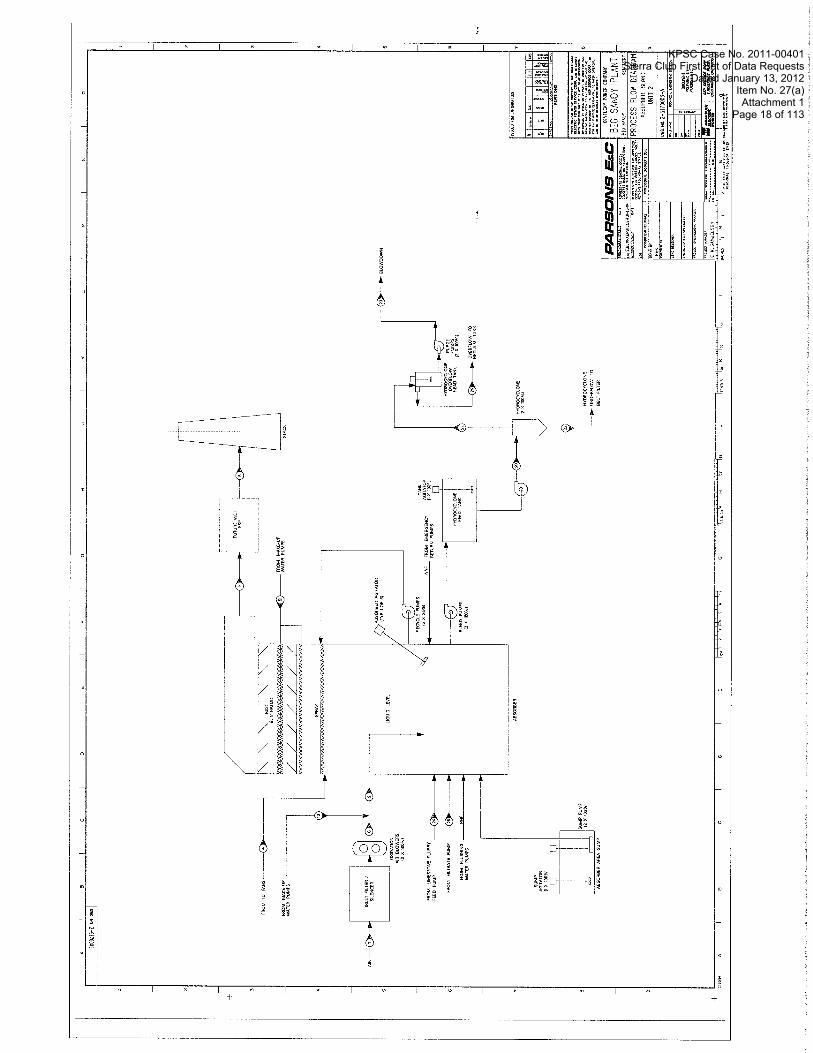
Full load operation of Unit 2 firing the design coal consumes approximately 775 tons of 92 % "active" calcium carbonate (CaC03) limestone per day. Limestone will be fed from a storage pile to silos located within the limestone preparation building. Two wet grinding ball mill systems will be installed. The mill systems will be located in the reagent preparation building. The mills produce limestone ground to 95 % passing 325 mesh. The ground limestone will be slurried with water that is either reclaimed from the dewatering process or with make-up water from the service water tank. The reagent slurry feed pumps forward the reagent slurry to the absorbers through a double pipe loop (independent) feed system. The reagent preparation building will be provided with an area sump for collection of slurry from process drains. The sump will be provided with two sump pumps that return the collected slurry to the limestone slurry storage tanks. The reagent preparation system is illustrated in drawing number 2-5 170000-B.
Gypsum dewatering will consist of two stages: primary and secondary. Primary dewatering will be achieved by hydrocyclone classification. Secondary dewatering will be accomplished with horizontal belt vacuum filters. A hydrocyclone cluster will be mounted above each vacuum belt filter. Hydrocyclone feed pumps will feed slurry from the feed tanks to the hydrocyclone classifiers. Overflow from the hydrocyclones will discharge through a common manifold to one overflow head tank. The head tank will overflow to a reclaim water tank. The reclaimed water will be returned to the absorber and/or the limestone grinding system to maximize the utilization of water and unreacted limestone contained in the hydroclone overflow. Underflow from each hydrocyclone classifier will be delivered to its associated belt filter. A simplified system arrangement for the
KPSC Case No. 2011-00401Sierra Club First Set of Data Requests
Dated January 13, 2012Item No. 27(a)Attachment 1
Page 19 of 113

KPSC Case No. 2011-00401Sierra Club First Set of Data Requests
Dated January 13, 2012Item No. 27(a)Attachment 1
Page 20 of 113

PARSONS EfiC
hydrocyclones and overflow tank is shown in Drawing 2-5 170003-A along with the absorber configuration.
Vacuum belt filters will be used to dewater hydrocyclone underflow to produce gypsum containing less than 10 percent moisture. The gypsum product will be conveyed to a storage pile at a rate up to 56 tph. Fresh makeup water, filtered and biologically treated river water, will be provided as seal water to the vacuum pumps and for washing the gypsum filter cake. Vacuum filter filtrate will be collected together with hydroclone overflow in the reclaim water tanks, and returned to the absorber reaction tank and/or ball mill grinding system by the two reclaim water pumps. The basic configuration of the vacuum belt filter system is shown on drawing 2- 5 170004-B. Sump pumps will be provided in the vacuum belt filter area to return collected liquids to the reclaim water tanks.
The concentration of chlorides, and/or solid fines material, in the absorber reaction tank will be controlled by an FGD blowdown or purge stream. The blowdown stream may or may not be treated prior to being routed to its ultimate destination, which may be a dedicated pond or the bottom ash pond. The source of the FGD blowdown stream will be the hydroclone overflow head tanks as shown on drawing 2-5 170003-A.
The FGD system requires significant quantities of makeup water to compensate for: water lost through evaporation in the FGD absorber, water lost with the FGD gypsum filter cake, and that purged from the system (blowdown) to control the concentration of chlorides and/or fines in the absorber. Strained, biologically treated, filtered water from the Big Sandy River, will be stored in the makeup service water tank from where it will be pumped to the various fresh water users. A schematic of the service water tank in shown in Figure 2-5170002-A. FGD service water pumps will provide fresh water to the absorber mist eliminator and oxidation air quench. The balance-of-plant service water pumps provide water to limestone grinding, vacuum pump seal water, water for slurry piping system flush out, for makeup (initial fill) of the absorbers, and for make-up to the reclaim tank.
4.2 Process Equipment List
The process flow diagrams, described above, and conceptual design criteria, presented in Section 3, were used to generate mass balances (Appendix A) of the conceptual combustion and WFGD systems. The process equipment list is shown in Appendix C. The equipment list is for reference only and not the product of detailed design. The equipment list in
KPSC Case No. 2011-00401Sierra Club First Set of Data Requests
Dated January 13, 2012Item No. 27(a)Attachment 1
Page 21 of 113

KPSC Case No. 2011-00401Sierra Club First Set of Data Requests
Dated January 13, 2012Item No. 27(a)Attachment 1
Page 22 of 113

KPSC Case No. 2011-00401Sierra Club First Set of Data Requests
Dated January 13, 2012Item No. 27(a)Attachment 1
Page 23 of 113

PARSONS EsC
Appendix C merely shows gross dimensions and equipment sizes and will change with refinements in design, margin application, and FGD OEM technology choice.
4.3 Conceptual Electrical Load List
The conceptual list of equipment to be powered by the Big Sandy Unit 2 FGD Electrical Distribution System is presented in Appendix D as List AEBS-2-LI-023-0001. Loads to be served by this system include those identified in the Process Equipment List (Appendix C), as well as projected non-process loads associated with FGD facilities lighting and HVAC systems, the new chimney, the new outdoor FGD substation, etc. The Appendix D list assigns process loads to electrical distribution system buses based on anticipated load power ratings, and on the desire to power redundant process loads from separate power sources. This latter approach will minimize process down time in the event of electrical equipment outages. The non-process loads are all envisioned to be 480V and are generally assigned to Common Load motor control centers to be located in load concentration areas.
The Electrical Load List is meant to account for all loads requiring electrical service; it is not the intent of the list to be used for the determination and optimization of bus demand loadings. Those analyses will be performed as part of the Phase I1 electrical system voltage studies. This Electrical Load List is envisioned to be a living document, to be expanded and updated as the Big Sandy FGD Project evolves.
4.4 Conceptual Electrical One Line Diagram
The conceptual One Line Diagram of the Big Sandy Unit 2 Electrical Distribution System is included in Appendix D as Sketch AEBS-2-SK-EZ- 206-001. The distribution system configuration, which is an abbreviated version of the Mitchell Units 1 and 2 FGD electrical system, provides sufficient redundancy of electrical equipment to allow for full FGD (process) operations under most credible electrical equipment failure scenarios. In addition, a Common Load switchgear lineup is included in the configuration for powering non-process loads. This concept of separating process and non-process load buses evolved in the Mitchell FGD Project due to the high magnitude of the combined process and non-process loads and the resultant adverse impact on the distribution system steady state voltage.
KPSC Case No. 2011-00401Sierra Club First Set of Data Requests
Dated January 13, 2012Item No. 27(a)Attachment 1
Page 24 of 113

KPSC Case No. 2011-00401Sierra Club First Set of Data Requests
Dated January 13, 2012Item No. 27(a)Attachment 1
Page 25 of 113

PARSONS EfiC
. _ ._ _ .. . .. .--.. - -. ., . . ... . . .. i(_,?_i._._:l.-__ ,r--ll-.- . - : ::. .; . . . .. . . . . . , , . .
Description of Conceptual Design .. . ,.. . , . . . . .. . -1 . . -. -- - - - .-.. ..- - .-. - -- . - - - .- -. . ... --- ..-- . . . ._ -1 - -L ._L2 . . l
The double-ended switchgear lineups depicted are operated with their tie breakers normally open, with each bus section receiving power from its incoming transformer and main breaker. In order to maintain continuity of service to all loads during an outage of any individual transformer supply, all transformers and buses will be rated to allow any single transformer in a double-ended switchgear arrangement to carry all load on a double-ended lineup. This will be achieved via manual or automatic closing of the lineup tie breaker in accordance with the control philosophy to be developed for the project.
Incoming power to the Big Sandy FGD Electrical Distribution System will likely be developed via modifications to the existing Big Sandy main 138kV switchyard - it is this method that is implied on the conceptual one line. Another option of FGD power supply would be to modify the existing Unit 2 SCR electrical distribution system, including 138-1 3.8kV transformers. This approach will be reviewed at the onset of Phase IIa; if adopted, the one line diagram will be revised accordingly. In any event, this one line will evolve, during Phase II, into the Big Sandy FGD Key One Line Diagram, complete with equipment identifiers and ratings.
The Appendix D conceptual One Line assumes that the new ID fans, intended for connection to 13.8kV Buses A and B, will be able to start and run satisfactorily with this connection without unacceptable degradation of system voltages. Should the horsepowers of the fan motors become too high for this configuration - resulting in unacceptable voltages during motor starting or steady state operation - connection of the motors in a different fashion will need to be investigated.
KPSC Case No. 2011-00401Sierra Club First Set of Data Requests
Dated January 13, 2012Item No. 27(a)Attachment 1
Page 26 of 113

PARSONS EsC
. . .. . ._ ._. _ _ _ - .+ .-* _.5___^.__._ _____,.._ ,_ _. . - - . I - 8 Conceptual Plot Plans and General ~ r rhgemen tb rawin~s . . .-. - . . I . . .. .. :. _ .-_.. -.I-.L..-L _r_. ... .-...- ;-:.- -:.-.-A_- ...- I i
5.1 Summarv
Two areas at the Big Sandy Site were considered for placement of the WFGD equipment and buildings. These are the areas north and south of Unit #2. In comparison to the north area, the south area is much smaller, has more existing underground utilities, would require relocation of warehouses and the Unit #2 Service Building, and would result in tight access to the south side of the Unit #2 boiler. One plot plan was considered for the south area. This is shown on drawing 2-507001A. Due to the disadvantages identified for the South arrangement, it is the least desirable of the areas considered.
The north area requires minimum utility relocation. The existing warehouse on the north side would not require relocation for the WFGD system. This warehouse may require relocation if a WESP is added in the future for SO3 control. Extension of the existing 138 kV switchyard will require modification to the two 12" HDPE ash slurry lines that run north/south on the east side of the switchyard to the ash ponds across the highway. This relocation will be required regardless of the location of the WFGD equipment and buildings. It became apparent that the north area had many advantages over the south area, at which point emphasis was placed on the north area. Two plot plans were considered for this area: Option 1 and Option 2 as shown on drawings 2-5070000B and 2- 5070000C, respectively. These plot plans were developed based on a tray tower type absorber. Arrangements for North Options 1 and 2, using an open tower type absorber, were also developed. An open tower absorber would increase the number of Absorber Recycle Pumps from five to eight, requiring a larger FGD Building. The drawings for the open spray tower arrangements are titled North Option - 118 and North Option - 218 and are shown on drawings 2-5070000E and 2-5070000D, respectively.
5.2 Recommended Plot Plan
The recommended plot plan for the WFGD buildings and equipment at Big Sandy Unit #2 is the North Option 2 arrangement, shown on drawing 2-5070000C for the tray tower type absorber and 2-5070000D for the open tower type absorber. These arrangements are similar to the North Option 1 arrangement with the following exception. The flue gas duct from the SCR outlet through the ID fans to the WFGD absorber inlet is oriented at a 35" angle from the east-west centerline of the existing stack, resulting in a lower pressure drop than the right angle arrangement in the North Option 1 design. Option 2 also moves the FGD buildings further to the east, in
KPSC Case No. 2011-00401Sierra Club First Set of Data Requests
Dated January 13, 2012Item No. 27(a)Attachment 1
Page 27 of 113

KPSC Case No. 2011-00401Sierra Club First Set of Data Requests
Dated January 13, 2012Item No. 27(a)Attachment 1
Page 28 of 113

KPSC Case No. 2011-00401Sierra Club First Set of Data Requests
Dated January 13, 2012Item No. 27(a)Attachment 1
Page 29 of 113

KPSC Case No. 2011-00401Sierra Club First Set of Data Requests
Dated January 13, 2012Item No. 27(a)Attachment 1
Page 30 of 113

KPSC Case No. 2011-00401Sierra Club First Set of Data Requests
Dated January 13, 2012Item No. 27(a)Attachment 1
Page 31 of 113

KPSC Case No. 2011-00401Sierra Club First Set of Data Requests
Dated January 13, 2012Item No. 27(a)Attachment 1
Page 32 of 113
PARSONS EsC
- - . - - - - - - - - - -- - - - - - . - , - - - - - - - -- - - - ~ b n c e ~ t u i i ~ l o t Plans and General Arrangement Drawings
- - -. . - - - - - - i - . I - . __-_- . _ . _ i
comparison to Option 1, which allows the FGD substation and FGD station service transformers to be located closer to the existing 138 kV Substation. This transformer location is also closer to the FGD Building and the ID Fans, where the largest electrical loads are located. The extension of the existing 138 kV switchyard will be necessary to accommodate switchyard equipment additions for FGD substation bulk power feeds. This arrangement also allows space for efficient location of the field erected tanks so that they are nearest to the primary users, thus minimizing piping runs.
5.3 Plot Plan Development Criteria
In development of the plot plans, the following arrangement criteria have been considered:
Minimize length of ductwork and pressure drop from the ESP outlet to the FGD absorber inlet. Ensure adequate space for operations and maintainability in and around the FGD Buildings and Equipment. Minimize the complexity of power transmission from the existing main 138 kV switchyard to the FGD substation, and from the FGD substation to the FGD electrical distribution equipment in the Ab- sorber Building. Ensure adequate space for operations and maintainability of all ex- isting Unit#l and 2 buildings and equipment. Ensure adequate duct runs in and out of equipment to provide good flow distribution and minimal pressure drop. Provide conveyor access to minimize transfer points and complexity of the limestone and gypsum handling systems. Include gypsum dewatering on site even though pumping the slurry across the road to a dewatering pond will be considered in Phase II as an alternative to onsite dewatering. Locate the limestone silo bay in the Reagent Prep Building adjacent to the FGD Absorber Building to allow access to the top of the silos from the FGD Building. Minimize duct length between absorber and chimney while allowing sufficient space for large underground foundations.
KPSC Case No. 2011-00401Sierra Club First Set of Data Requests
Dated January 13, 2012Item No. 27(a)Attachment 1
Page 33 of 113

PARSONS EslC
._ " .,-_ ;__ ._. .__,____l___.l____.___.l_^ .... -. .,-. ._ _ ____.I.._ conceptud'Plot plans . . and, General ~rrangement . . Drawings I - 8 . . . . .. . . - -- --_;-.>..- -. --. - - - - - - ; J
5.4 General Arrangements
General Arrangements for the ground floor of the FGD Building, Reagent Prep Building and the Dewatering Area Building are shown on drawings 2-5070002A, 2-5070003A, and 2-5070004A, respectively. These general arrangements are based on the Mitchell Unit #1 and #2 tray tower design with modifications for single rather than two unit design. Redundancy of equipment is based on the Mitchell Station arrangement and criteria in the AEP Program Buying Guide for Major Process Equipment Sizing.
Mitchell Units #1 and #2 are sister units to Big Sandy Unit #2 with comparable heat input and flue gas flow rate. The Mitchell design is based on burning coal having a maximum sulfur content of 4.5 lb S02/MM Btu for the current design with provision for future conversion to allow burning coal having a maximum sulfur content of 7.5 lb S02/MM Btu. The current Mitchell design, downsized for a single unit and without provision for future higher sulfur coal capability, is a valid basis for the Big Sandy Unit 2 FGD arrangement.
Some of the equipment used in the Mitchell General Arrangements is oversized for the actual required duty. This is based on determining the required size of the equipment component and then picking the standard equipment size from the AEP Program Buying document that is equal to or larger than the required size. The AEP Program Buying document applies to the ball mills, vacuum belt filters, recycle pumps, oxidation air compressors and ID fans. It may be possible to downsize some of these components for Big Sandy Unit 2, if the Program Buying criteria is not applied and the actual required size equipment is purchased rather than a standard size. For the preliminary general arrangements, the equipment sizes shown are conservative.
Regarding redundancy, the major equipment, based on the Mitchell design, but adjusted in size for one unit at Big Sandy #2, is spared as follows:
Two ball mills, 1 operating and 1 spare Two vacuum belt filters, 1 operating and 1 spare Five recycle pumps (based on tray tower absorber), 4 operating and 1 spare Two oxidation air compressors, 1 operating and 1 spare
KPSC Case No. 2011-00401Sierra Club First Set of Data Requests
Dated January 13, 2012Item No. 27(a)Attachment 1
Page 34 of 113

KPSC Case No. 2011-00401Sierra Club First Set of Data Requests
Dated January 13, 2012Item No. 27(a)Attachment 1
Page 35 of 113

SCALE IN FEET
PLAN - GROUND FLOOR REAGENT PREPARATION AREA
KPSC Case No. 2011-00401Sierra Club First Set of Data Requests
Dated January 13, 2012Item No. 27(a)Attachment 1
Page 36 of 113

KPSC Case No. 2011-00401Sierra Club First Set of Data Requests
Dated January 13, 2012Item No. 27(a)Attachment 1
Page 37 of 113

PARSONS EaC
- - - -- -- - --- -.- - . --- -- - - ~ o n c e ~ ~ a l ~ l o t Plans and General Arrangement Drawings i
. - -. - .- - - - - . . - -. - - . - - - - - - - - -- - -. - -- - - -. - - 1
5.5 Stack Location
The plant coordinates of the new FGD stack are shown on Drawing 2-5070000C, the recommended North Option 2 arrangement. This location is based on preliminary equipment and building sizes and can be optimized, as allowed by the permitting schedule, when FGD OEM general arrangements and equipment sizing becomes available.
5.6 Big Sandy Unit1 Layout Considerations
Drawings 12-5070000A , 12-5070000B , and1 2-5070000D are plot plans showing a wet FGD arrangement that includes retrofit to Unit #1 in conjunction with Unit #2. The three drawings show the same combined Unit#l and 2 FGD absorber, reagent preparation, and dewatering arrangement. The difference in the three drawings is in the arrangement of the Unit#l ID fans relative to the Unit #2 ID fans. On drawing 12- 5070000D, the Unit #1 ID fans are located under the Unit #2 flue gas duct. The FGD system components have been factored in size for the additional flue gas entering the system from Unit #1 (275 MW gross and 2,602 mm Btulhr full load firing rate). An additional recycle pump, for a total of six, will be required for the open tray tower design. The quantities of the remaining major mechanical equipment components will not change, but the actual sizing criteria for the equipment will be adjusted to account for the approximate 113 increase in flue gas flow to the absorber when Unit 1 flow is combined with the Unit #2 flow.
For a two-unit FGD installation, the FGD substation area would be expected to increase to accommodate a total of four FGD Auxiliary Transformers, and the quantity of station service transformers required would also increase to four. These quantities are consistent with those of the two-unit Mitchell FGD electrical system.
KPSC Case No. 2011-00401Sierra Club First Set of Data Requests
Dated January 13, 2012Item No. 27(a)Attachment 1
Page 38 of 113

KPSC Case No. 2011-00401Sierra Club First Set of Data Requests
Dated January 13, 2012Item No. 27(a)Attachment 1
Page 39 of 113

KPSC Case No. 2011-00401Sierra Club First Set of Data Requests
Dated January 13, 2012Item No. 27(a)Attachment 1
Page 40 of 113

KPSC Case No. 2011-00401Sierra Club First Set of Data Requests
Dated January 13, 2012Item No. 27(a)Attachment 1
Page 41 of 113

PARSONS ELEC
.-.-.. ? - .-. -. - ..... - .............. , - ..... - . . . . . . . . . . . . . . . . . . . . . . . . . . . . . . . . . . . . . . . . . . . . . . . . . . . . . . , .
Phase lla Objectives ... ' I ...--..........----.. i .......................................... ..J
6.1 Introduction
Phase IIa will involve the integration of planning, conceptual studies and economic assessments, design criteria formulation, site layout design, and primary OEM equipment vendor information for the FGD systems. In Phase IIa, detailed engineering and design efforts will begin in earnest. Because of the schedule necessitating the need for a complete project cost estimate, Phase IIa engineering efforts will be geared toward the formulation of complete project definition to allow proper estimation of the current efforts' equipment sizing, quantities, craft labor, and continued engineering. While the current Phase I work is being completed, efforts involving all of the engineering disciplines for detailed planning of facilities locations and systems design will begin. The initial concentration of engineering will focus primarily on the civil, structural, and mechanical work. The civil work is associated with survey locations, subsurface utility investigations, geotechnical assessments, erosion and sedimentation plans, as well as, storm water system and excavation and fill calculations. The early structural engineering efforts in addition to design criteria development will include preparation of technical specifications, preliminary foundation designs for the absorber and chimney, and lasergrammetry for definition of as-built conditions of tie-in locations and planned duct routing. Foundation design for the chimney and absorber will be finalized after receipt of certified vendor load information. The mechanical work will involve development of ID fan sizing calculations and specification, definition of limestone and gypsum handling systems and specifications, development of balance-of-plant flow diagrams, writing of balance-of-plant equipment specifications, development of piping line specifications, and writing of technical specifications for piping, insulation, and mechanical equipment installation.
The process, electrical, and structural engineering disciplines during this initial period will be finalizing process flow diagrams and one-line diagrams, developing system and equipment sizing calculations, formulating new underground utility systems and grounding grids, beginning preparation of demolition drawings, and interfacing heavily with the FGD OEM vendor in order to obtain the critical system and foundation design information that is essential for the design of their respective foundations. During this initial period, the 3-D PDS model will be developed as the project's basic tool for the integration of the various disciplines' detailed design effort. [The FGD OEM vendor will be required to provide their equipment's 3-D models for use by Parsons E&C in the development of the overall integrated plant 3-D model.]
KPSC Case No. 2011-00401Sierra Club First Set of Data Requests
Dated January 13, 2012Item No. 27(a)Attachment 1
Page 42 of 113

PARSONS EkC
. . . . . . . . . . . . . . . . . . . . . . . . . . . . . . . . . . . . . . . . . . . . .-, . . '- . . . . . . . Phase . . ... Ila Objectives ........... . . . ., . . . . . j -.. ........ 2 - :-. ...... -_-A
The conclusion of the Phase IIa efforts will be a complete project estimate that will allow AEPSC to understand the capital commitment necessary to complete this project. It is anticipated that the Design Review Board (DRB) approval of the project will be coincident with the completion of the project cost estimate. The Parsons E&C team is committed to support the AEPSC Big Sandy team during the DRB approval process.
6.2 Maior Issues To Be Addressed in Phase Ila
AEPSC and Parsons E&C have jointly developed studies and evaluations that define the known major issues and open actions that will require further effort to completely define the overall project. Following is a listing of these elements with a short description for each, as well as the work to be performed.
Schedule Acceleration Study
Big Sandy Unit 2 WFGD commission date is currently scheduled for November 22, 2009. Parsons E&C will identify what strategic activities need to be initiated and what project milestones need to be completed in order to accelerate this WFGD commissioning date.
Permitting Support
By this activity Parsons E&C will provide AEP with services required, time-to-time, to support on-going issues associated with the air, water, or site permitting processes. These issues would include, but are not confined to, material balances for alternative coals, limestones, or ambient conditions, review of documented state or local emissions/effluent regulations, revised emission or effluent calculations, trace element emissions, andlor supporting calculations.
Design Review Board Support
AEP may request support from Parsons E&C in preparing and/or presenting material to AEP Senior Management. This support may take the form of, but is not limited to, review of presentation material, generating presentation documents, and travel to Columbus, Ohio to support the AEP project team.
KPSC Case No. 2011-00401Sierra Club First Set of Data Requests
Dated January 13, 2012Item No. 27(a)Attachment 1
Page 43 of 113

PARSONS EsC
Site Safety Study
Parsons E&C will walk the site to see what potential construction hazards exist. The overall study will take the following form: 1) Review access and egress for safe construction operations and minimal conflict with plant operations. 2) Highlight areas for confined space entry permitting. 3) Review worker pedestrian areas for safe site access. 4) Establish preliminary safe work zone boundaries. 5) Evaluate road crossings and recommend special traffic controls for safe construction operations. 6) Review site for "Overhead Power Line" restrictions and recommend appropriate postings for construction clearances. 7) Review existing structures affected by construction for "Tie Off' requirements. 8) Issue a report on existing conditions, analysis of hazards or potential hazards, and recommend corrective actions or accident prevention measures.
Big Sandy Unit 1 Emissions Control Strategy
Parsons E&C may, if directed by AEP, evaluate the application of several emissions control technologies to Big Sandy Unit 1 for the purposes of reducing mercury emissions. The emission controls will focus on deNOx and deSOx technologies, such as SCR and W G D , as well as commercial mercury removal systems. WFGD control technologies evaluated may or may not include the same WFGD technology applied to Big Sandy Unit 2. The emissions alternatives evaluated will weigh overall results with risk, cost, schedule, and commercial reliability. A study report would be issued for this work.
Big Sandy Unit 1 Alternatives and Risk Assessment
Parsons E&C may, if directed by AEP, identify and evaluate the risks associated with the application of emissions control technology(s) to both Big Sandy Units 1 and 2. Issues to be evaluated may include: the impact of additional ammonia requirements for Unit 1 on the existing urea-to- ammonia plant, affect of Unit 1 technology to the general arrangements and plot plans already developed by Parsons E&C for Unit 2 WFGD, and additional utility requirements for Unit 1 conversion. If the same WFGD control technology is applied to both Units 1 and 2, additional studies will be required. These additional studies may include, but are not limited to, routing flue gas from both Unit 1 (300 MW) and Unit 2 (800 MW) to the same absorber vessel, evaluating induced draft damper configurations required to isolate off-line unit, evaluating affect of "off-line" Unit 2 on location of wet/dry line when Unit 1 "on-line" at part load, and total unit response to master fuel trip (MFT), or other such plant disruption, on either Big Sandy Unit 1 or 2.
KPSC Case No. 2011-00401Sierra Club First Set of Data Requests
Dated January 13, 2012Item No. 27(a)Attachment 1
Page 44 of 113

PARSONS EsC
.. -- - .. .. , .- . - * .. - . >- ..... - . . .
. . phase . . Ila Objectives . :.. : .. . ' . : : i I
Limestone and Gypsum Weather protection
Parsons E&C will make an assessment to determine if raw limestone requires measures for freeze protection and dust control. The same evaluation will be made for the gypsum product. A report will be issued for this study.
Plant Operating Data
Historical plant data summaries will be evaluated by Parsons E&C to determine normal base line and part load operating levels, as well as to determine required turndown requirements and capabilities. Examination of the historical data will also reveal if the unit is a "peaker" or traditional "base loaded" unit. AEP will be interviewed to determine the future disposition of daily operations to make sure they are consistent with historical data. The summarized data will be incorporated into the plant specific design criteria
Plant Operating Philosophy
Parsons E&C will interview the appropriate AEP personnel to determine the preferred schedule for batch operations such as: raw limestone grinding, limestone slurry preparation, and gypsum dewatering. These operations may be confined to two shifts rather than three. Plant preferences will determine storagelsurge tank volumes. The summarized results will be incorporated into the plant specific design citeria.
Shared Assets
The potential effects of Unit 2 WFGD conversion to Unit 1 will be evaluated by Parsons E&C. This would include changes in coal feedstock necessitating separate coal deliveries, storage, and handling for Unit 1. Other variables will be identified and investigated such as shared electrical tie-ins, flyash disposal options, and the potential for conversion of Unit 1 for SCR and WFGD.
There are also potential effects of adding WFGD to Unit 2 on existing Unit 2 equipment. These effects need to be identified and quantified. One example of this is if ammonia is chosen for in-duct SO3 mitigation. The existing urea-to-ammonia facility would have to be examined to ensure that it can provide the required ammonia for both the existing Unit 2 SCR as well as the potentially required ammonia for SO3 mitigation.
A report will be issued for this study.
KPSC Case No. 2011-00401Sierra Club First Set of Data Requests
Dated January 13, 2012Item No. 27(a)Attachment 1
Page 45 of 113

PARSONS EGC
--_i7-; -;--?----.- -;-r .. ...- .-- - -- . . -. . . - - - .. . - . . . . . I
Phase: 11s Objectives . . . . . . . ! .: - . .;-- 1 --,. ... .- ..-: .-... . .... . .I
Baseline Plant Test
A third party will be contracted by AEP to perform a rigorous and comprehensive survey of plant state points and other data. This data will be reviewed and reconciled by Parsons E&C against historical plant operating data. Plant personnel will be interviewed to assess the accuracy of the baseline test data and to help reconcile any inconsistent information. The results will be reflected in the plant specific design criteria.
High Sulfur Coals
AEP will perform any evaluations required to determine the effect of burning higher sulfur coal on unit operations, including the boiler, air heater and ESP.
Redundancy
Before final plot plans and General Arrangement drawings can be developed, a WFGD equipment redundancy policy must be established. In its simplest form, such a policy requires specifying redundant critical equipment as either: (1) two units sized for full load - one unit operating and one spare, or, (2) three units sized for half load - two units operating and one spare. It is anticipated that redundancy requirements will be mutually resolved by AEP and Parsons E&C during design development.
SO, Mitigation Study
SO3 mitigation method will be determined by AEP. AEP does not want Parsons E&C to perform a study of viable options. Implementation of the mitigation system selected by AEP is in Parsons E&C scope of detailed design.
Limestone Specification
It is essential that we finalize limestone "design" composition and identify likely alternatives. This requires a review of limestone available by railcar and a definition of the gypsum product as either disposable or wallboard quality. Once the design limestone is identified, the trace element analysis for purposes of permitting the unit needs to be verified. The final limestone specification, decision on disposable vs. wallboard quality gypsum, and trace element analysis of the limestone is in AEP scope of work. Parsons E&C will perform the trace element analysis of byproducts and wastewater.
KPSC Case No. 2011-00401Sierra Club First Set of Data Requests
Dated January 13, 2012Item No. 27(a)Attachment 1
Page 46 of 113

PARSONS EslC
Gypsum Dewatering
A decision by AEP is required on the ultimate disposition of the solids produced in the WFGD process. It must be agreed upon as to whether a salable gypsum product is to be produced or if the WFGD solids are to be disposed of in either a landfill or pond. The choice will allow assessment of the dewatering method and disposal options. The final dewatering option may affect the size of the plot plan, typelsize of oxidation blower required, bulk dewatering equipment required, as well as the quality of limestone required.
FGD Supplier
A WFGD OEM must be selected by AEP with input and guidance from Parsons E&C. Choice of technology will affect all other aspects of the plant design and is an important issue that must be evaluated and weighed with cost, risk, reliability, and schedule in mind.
Chimney Studies
Parsons E&C will need to finalize the chimney location. AEP will specify the chimney height and complete turbulence and dispersion tests. Parsons E&C will evaluate potential breeching configurations and determine if the use of FRP ductwork from the absorber hood is feasible or if squarelrectangular ductwork is required. The work in Parsons E&C scope is part of design development.
Power Source Study
There are two options for providing redundant sources of power to the Unit 2 WFGD electrical distribution system. One option involves the use of the existing Unit 2 138- 13.8kV SCR transformers and SCR 13.8kV switchgear. Modifications and/or partial replacement of this equipment would likely be necessary for this option to be feasible. The other option involves the addition of 138kV breakers in the existing Big Sandy 138kV switchyard, and the extension of new 138kV transmission circuits to a new 138-1 3.8kV FGD substation located adjacent to the FGD development area. Parsons E&C will perform an assessment of these alternatives and provide a recommendation for AEP's approval.
Rail Delivery or Truck Delivery
A final determination must be made as to whether rail cars or trucks will be used for the delivery of coal, limestone, and perhaps dewatered gypsum.
KPSC Case No. 2011-00401Sierra Club First Set of Data Requests
Dated January 13, 2012Item No. 27(a)Attachment 1
Page 47 of 113

PARSONS EGG
This decision must be weighed against the risks, cost, and benefits of each alternative. Parsons E&C will perform this study and issue a report.
Make-up Water Supply
Potential water make-up sources will be identified and quantified. Make- up water sources include river water, ash pond run-off, and well water. Make-up water trace element compositions will be evaluated. Pre-treatment alternatives for biological and solids removal will be evaluated. Modifications to the existing river water intakes will be evaluated as necessary. Parsons E&C will perform this study and issue a report.
Coal System Upgrades
Coal feed to Unit 2 will be a blend of high and low sulfur coals. A coal blending system will have to be developed. An approach to maintaining two separate coal piles for Unit 2 will also need to be developed. Parsons E&C will examine rail traffic schedules to determine what impact will be realized through delivery of two separate coal sources. Parsons E&C will perform this study and issue a report.
Blow Down
The ultimate disposition of the WFGD purge stream effluent must be determined and verified. Once the location is determined, a trace element analysis will be required, along with an evaluation of state regulations, as to whether the purge effluent requires additional clarification andlor treatment. This work will be done by Parsons E&C as part of the design development.
Topographic Survey
Parsons E&C will prepare a drawing and specification to procure topographic survey services. The survey will include identification of surface features and will provide existing topographic information for the existing plant necessary for design. The survey will be performed by a professional land surveyor. A Parsons E&C representative will be on site during the surveyor's fieldwork.
Geotechnical Investigations and Report
A subsurface exploration program will be performed at the site. Parsons E&C will review existing geotechnical information, and then propose additional subsurface investigations as warranted. A drawing and
KPSC Case No. 2011-00401Sierra Club First Set of Data Requests
Dated January 13, 2012Item No. 27(a)Attachment 1
Page 48 of 113

PARSONS EfiC
specification will be provided by Parsons E&C for AEP to procure these services. The program will likely include standard penetration test (SPT) borings, rock cores, field resistivity testing, shear wave velocity testing, and laboratory testing of soils. A Parsons E&C representative will be on site during the fieldwork. The results of the geotechnical investigation will be provided to Parsons E&C as a data report and Parsons E&C will use this data to generate geotechnical design recommendations.
Underground Utility Investigations and Report
Parsons E&C will review existing utility drawings available for the site and then prepare recommendations for a subsurface utility locating program. Parsons E&C will prepare a drawing and specification for AEP to procure these services. This work will be performed in general accordance with American Society of Civil Engineers (ASCE) 38-02, "Standard Guideline for the Collection and Depiction of Existing Subsurface Utility Data." Most likely the services will consist of Quality Level B geophysical methods for designating utilities in accordance with ASCE 38-02 with some Quality Level A locating on an "as-needed" basis. Quality level C services will be provided as part of the topographic survey. A Parsons E&C representative will be on site during this fieldwork.
River Intake - Bathymetric Study
If required, Parsons E&C will prepare a drawing and specification for AEP to procure bathymetric survey services to obtain river water depths in the area of the proposed river intake. This will only be required if modification to the existing intake is necessary to add pump(s) to meet makeup water requirements of the WFGD system. These services may or may not be performed by the same surveyor who performs the separately listed topographic survey. A professional land surveyor will perform the survey with equipment specifically manufactured to obtain water depth reading or soundings. A Parsons E&C representative will be on site during this fieldwork.
Transient Analysis
A dynamic (time dependant) model maintaining the integrity of the existing plant geometry while incorporating the new absorber gas-path geometry will be developed. This model will be used to investigate gas-path transient responses in order to estimate peak pressures in the flue gas system to determine design pressure of the gas side ductwork and equipment. AEP will perform this work and provide design pressures to Parsons E&C for the ductwork in the AE's scope of design.
KPSC Case No. 2011-00401Sierra Club First Set of Data Requests
Dated January 13, 2012Item No. 27(a)Attachment 1
Page 49 of 113

PARSONS EisC
. . - - - .1_1.._1--7.--_.-- .- ., - . .-----_--._._.I.-. _ _ ̂ _... ' -r--7 ---'-< '- . . . . . . Phase Ila Objectives . ,
. _ . ' -7 . ' ..,.:, .. d . . . . . - . -. L.r L-.:.:I~~I;.: rrJ
Construction Approach
Several approaches to construction for this plant can be used. It is the intent of AEP and Parsons E&C to develop an approach that is consistent with the objectives of a safe working environment, acceptable schedule, and cost-effectiveness. Parsons E&C will evaluate the site specific needs, project schedule, complexity of equipment, and make the most appropriate recommendation while considering the project cost and risk profile for the project.
Noise Study
Parsons E&C will write a specification for use by AEP to procure the services of a noise consultant to perform a survey of existing background noise at the plant boundary lines, determine the allowable noise levels at the boundary lines when the FGD plant is in operation, make recommendations on limits of equipment noise levels and acoustical treatment of outdoor equipment, ductwork, and buildings (louvers, building construction, etc.) to assure that allowable boundary line noise levels are not exceeded, and to perform a noise survey of actual levels at the boundary lines with the FGD plant in operation. Parsons E&C will review the consultant's report and incorporate their recommendations into equipment specifications.
KPSC Case No. 2011-00401Sierra Club First Set of Data Requests
Dated January 13, 2012Item No. 27(a)Attachment 1
Page 50 of 113
PARSONS EfiC
...-......... -. . -- - .............. , .. , .. ,- ........................... , . . . ................... , .. , .. - ................ . . Big . . Sandy Unit . . . 1 Incremental Issues . . . ,
- 8 . . . . L . . ,. ................................................ . .
1 . , 2
7.1 Incremental Issues with Adding WFGD to Big Sandy Unit 1
The issue to add a WFGD technology to Big Sandy Unit 1 has been raised by AEP. The approach is that the flue gas from Units 1 and 2 would be commonly ducted to a single absorber tower and ultimately to a single wet stack. Reagent preparation and product dewatering would be common. The gas paths from the individual units would remain separate through induced draft fans, dedicated to each unit, and combined, where appropriate, prior to the absorber inlet duct. Three conceptual layouts for the combined FGD system can be found in Section 5 of this report.
Prior to adding WFGD to Big Sandy Unit 1, a life-extension program, that may include furnace conversion from pressurized to balanced-draft, would be required. This is due to the decayed state of the existing furnace and ductwork. This necessary program would extend the life of the power generator by twenty years. For the purposes of this discussion, Parsons E&C is assuming that both a life-extension program and a furnace draft conversion program could be completed without much risk to plant availability and at a known cost.
A design challenge lies in ducting the Unit 1 flue gas to the common absorber inlet duct. The difficulty lies in spatially accommodating the ductwork from the ESPs to the common absorber tower, from both Unit 2 and Unit 1. With the two units positioned back-to-back and exhausting into a common stack (existing hot stack), the ductwork egresses from each individual unit will be tight. The existence and/or level of possible interferences will remain unknown until both units are evaluated three dimensionally subject to application to a common WFGD tower.
There are other issues that introduce uncertainty and would require evaluation and definition to mitigate risk. These would include but not be limited to: (1) evaluating ID fan damper configurations required to isolate an off-line unit, (2) evaluate effect of "off-line" Unit 2 on location of the absorber wetldry line when Unit 1 is "on-line" at part load, (3) effect of Unit 1 WFGD on the general arrangements and plot plans already developed by Parsons E&C for Unit 2 WFGD, (4) electrical and other service requirements for additional capacity required to accommodate Unit 1 flue gas flow, and, (5) total unit response to master fuel trip (MFT), or other such plant disruption, on either Big Sandy Unit 1 or 2.
There is a large amount of risk associated with proceeding on Unit 2 WFGD without making a decision over the final disposition of Unit 1. This
KPSC Case No. 2011-00401Sierra Club First Set of Data Requests
Dated January 13, 2012Item No. 27(a)Attachment 1
Page 51 of 113

PARSONS E'C
_- .- .. - . . -.._ -_ _ ._ . -. _._ ..,. ___l_l__.C__.. _ . . . , . . .. .. , Big Sandy'Unit 1 Incremental Issues .:, . - - . , , . ;: ._ -, . . . . . . . . . i
. . - . I _ . . . - L. -. - --2 ... .__._-_-__I --.-.- .. 1 --. 1
risk could adversely affect both cost and schedule for Unit 2 WFGD. Comments from plant personnel received by Parsons E&C during the project kick-off meeting indicated a high level of concern in proceeding with WFGD for Unit 2 without planning for and incorporating modifications to Unit 1.
7.2 lncremental Issues with Addina SCR to Bia Sandv Unit 1
It has been proposed that if WFGD were applied to Big Sandy Unit 1, a selective catalytic reduction (SCR) system would be concurrently added. This would entail ducting the hot flue gas from the economizer exit to the SCR system and then ducting the flue gas back to the air heater. From the air heater, flue gas would flow through the ESP and ultimately be routed to the common absorber tower.
A typical SCR system consists of an ammonia injection grid (AIG), static mixing of the flue gas and ammonia, and a multiple-bed catalytic reactor. The SCR AIG and reactor must be supported above grade in close proximity to the economizer. Grade-level real estate would have to be located to accommodate the steel. Proper planning would be required to configure the Unit 1 SCR along with the ductwork changes required to route the flue gas to the WFGD absorber tower. Discussion with Big Sandy plant personnel has hinted at the possible relocation of the Unit 1 ESPs. Again, as is the case with the WFGD discussed above, both Units 1 and 2 would have to be evaluated in three dimensions to properly assess and refine this combination. Proceeding without addressing these issues would potentially expose the Unit 2 WFGD design to deficiencies and risk that would undermine the overall project.
Other issues that would have to be evaluated include: general assessment of furnace access for SCR, electrical and other service requirements for SCR addition, impact of additional ammonia requirements for Unit 1 on the existing urea-to-ammonia plant, and the effect of Unit 1 SCR and WFGD on the general arrangements and plot plans already developed by Parsons E&C for Unit 2 WFGD.
7.3 Incremental lssues with Addina Unit 1
One of the possibilities for dealing with mercury control is the installation of an SCR and WFGD for the Big Sandy Unit 1. We have established incremental cost estimates associated with combining the Unit 1 WFGD with the Unit 2 WFGD, vis a vis, Unit 1 and Unit 2 steam generators into
KPSC Case No. 2011-00401Sierra Club First Set of Data Requests
Dated January 13, 2012Item No. 27(a)Attachment 1
Page 52 of 113

PARSONS EkiC
................... , ..... . . - ....... - - ......-.. ... ..,....,. . . . . . . .
. , . I
. . . . . . . - I Big Sandy Unit 1 Incremental Issues ., . . . , , . I .-......... -.:. . : .. -- .-... 3
one FGD absorber tower. The incremental costs were evaluated by having unitized draft systems up to the absorber vessel. Thus each unit has its own dedicated duct from the ESP outlet to the WFGD absorber including two axial ID Fans.
The incremental costs were determined by using the Mitchell Units 1 and 2 project cost estimates to determine a relative estimate for the Big Sandy Unit 2 overall cost. This was then factored based upon judgment for the incremental increase of the equipment size to incorporate the processes of the 300 MW Unit 1. Following is a tabulation of these incremental costs:
The above estimated incremental cost breakdown relates to approximately $197/KW and was established by using the same ratio to the total costs as was established for the Mitchell costs. These values include AEPSC's costs, assumed to be in the same proportion as the Mitchell project, but do not include Water Treatment, Coal Blending and SO3 Mitigation costs.
WF'GD System Description
Absorber Island
Flue Gas Draft System
Limestone Handling and Slurry Preparation System
Gypsum Dewatering and Handling System
Electrical and I&C Systems
Chimney
Balance of Plant Equipment
Foundation and Site Preparation
TOTAL INCREMENTAL COST
Regarding the SCR incremental cost, it is Parsons' experience that a ratio of $100 per KW is a relatively accurate cost estimate. Applying this ratio, incremental costs for a Unit 1 SCR would be approximately $30 million. This is based upon it having its own dedicated urea to ammonia conversion system.
Cost (x 1000)
$1 1,400
$16,150
$5,700
$5,700
$5,950
$4,200
$3,700
$6,400
$59,200
KPSC Case No. 2011-00401Sierra Club First Set of Data Requests
Dated January 13, 2012Item No. 27(a)Attachment 1
Page 53 of 113
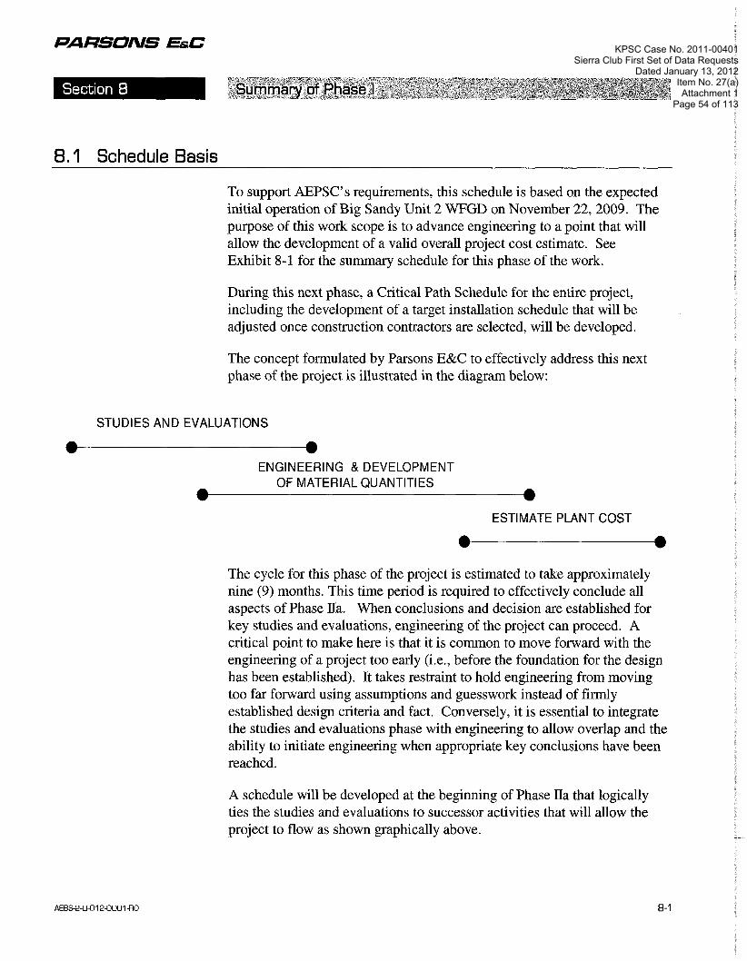
PARSONS EfiC
8.1 Schedule Basis
To support AEPSC's requirements, this schedule is based on the expected initial operation of Big Sandy Unit 2 WFGD on November 22,2009. The purpose of this work scope is to advance engineering to a point that will allow the development of a valid overall project cost estimate. See Exhibit 8-1 for the summary schedule for this phase of the work.
During this next phase, a Critical Path Schedule for the entire project, including the development of a target installation schedule that will be adjusted once construction contractors are selected, will be developed.
The concept formulated by Parsons E&C to effectively address this next phase of the project is illustrated in the diagram below:
STUDIES AND EVALUATIONS
ENGINEERING & DEVELOPMENT OF MATERIAL QUANTITIES
ESTIMATE PLANT COST
The cycle for this phase of the project is estimated to take approximately nine (9) months. This time period is required to effectively conclude all aspects of Phase IIa. When conclusions and decision are established for key studies and evaluations, engineering of the project can proceed. A critical point to make here is that it is common to move forward with the engineering of a project too early (i.e., before the foundation for the design has been established). It takes restraint to hold engineering from moving too far forward using assumptions and guesswork instead of firmly established design criteria and fact. Conversely, it is essential to integrate the studies and evaluations phase with engineering to allow overlap and the ability to initiate engineering when appropriate key conclusions have been reached.
A schedule will be developed at the beginning of Phase IIa that logically ties the studies and evaluations to successor activities that will allow the project to flow as shown graphically above.
KPSC Case No. 2011-00401Sierra Club First Set of Data Requests
Dated January 13, 2012Item No. 27(a)Attachment 1
Page 54 of 113

PARSONS EfiC
8.2 Proiect Critical Path
The critical path through the project lies with the permitting activities. If the permitting activities' schedule can be improved, the critical path in moving forward will then lie with chimney erection and construction of the WFGD absorber. Erection of the chimney shell will essentially prevent other craft activity in the FGD area due to safety requirements. At a minimum, a fifty (50) foot safety exclusion zone (radius) is required around the stack during construction. Therefore, it is important to establish the stack location and mobilize a chimney contractor early in the project. As soon as the chimney shell is erected, construction on the absorber and process buildings can commence.
Related to this string of construction activities at the front end of the schedule is the necessity to complete relocations and foundations in the chirnney/FGD island area. Since the chimney erection will impede other FGD area work, the schedule will need to provide for completing the entire FGD island foundations prior to start of the chimney shell. This will perrnit absorber island building construction immediately after the completion of the chimney shell, which otherwise would be delayed if foundations were not previously installed.
8.3 Engineering Schedule
The engineering schedule is dependent upon timely completion of the Phase IIa evaluations and studies that need to be finalized prior to the start of detailed engineering. The major deliverable for this next phase is the project cost estimate. Once the cost estimate is completed, and continued detailed engineering is authorized, the construction and commissioning schedules will be the driving factors to meet the required WFGD startup date. The key to success is the timing of engineering information from the OEMs and vendors to support balance-of-plant engineering and construction. Therefore, it is essential that orders to suppliers be released as required to support the overall schedule, thus preventing undue and unnecessary work schedule conflicts and delays.
KPSC Case No. 2011-00401Sierra Club First Set of Data Requests
Dated January 13, 2012Item No. 27(a)Attachment 1
Page 55 of 113

PARSONS EfiC
8.4 Division of Work
A complete project Division of Work (DOW) was jointly developed by AEPSC and Parsons E&C. The intent of this DOW is to define what company is responsible to perform all the work elements and supply all the materials for the project. This DOW is expected to be a living document, but provides a current baseline for documentation of intended project development. We have included as Exhibit 8.2 this Division of Work.
KPSC Case No. 2011-00401Sierra Club First Set of Data Requests
Dated January 13, 2012Item No. 27(a)Attachment 1
Page 56 of 113

PARSONS EktC
Exhibit 8- 1
KPSC Case No. 2011-00401Sierra Club First Set of Data Requests
Dated January 13, 2012Item No. 27(a)Attachment 1
Page 57 of 113

29NOV04 @:49
Proposal Schedule
KPSC Case No. 2011-00401Sierra Club First Set of Data Requests
Dated January 13, 2012Item No. 27(a)Attachment 1
Page 58 of 113

Sheet 2 of 4
KPSC Case No. 2011-00401Sierra Club First Set of Data Requests
Dated January 13, 2012Item No. 27(a)Attachment 1
Page 59 of 113
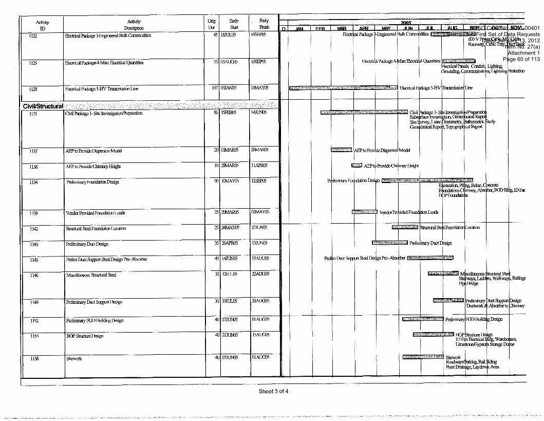
Sheet 3 of 4
KPSC Case No. 2011-00401Sierra Club First Set of Data Requests
Dated January 13, 2012Item No. 27(a)Attachment 1
Page 60 of 113

Sheet 4 of 4
KPSC Case No. 2011-00401Sierra Club First Set of Data Requests
Dated January 13, 2012Item No. 27(a)Attachment 1
Page 61 of 113

PARSONS EfiC
Exhibit 8-2
KPSC Case No. 2011-00401Sierra Club First Set of Data Requests
Dated January 13, 2012Item No. 27(a)Attachment 1
Page 62 of 113

Big Sandy Plant - Unit 2 WFGD Total Project Scope Split Target Cost Option
aft System Implosion Study & Transient Analys~s r Computer Flue Gas Model Study (FGD Scope of Supply)
Phys~cal or Computer Flue Gas Model Study (BOP Scope of Supply) Geotechn~cal Study Topograph~cal Surveys Baseline Testlng
Underground Utility Survey Lasergrammetry of Tie-In Polnts Chimney Proxlm~ty Effect Coal Blendlng Study Ammon~a Bt-Sulphate condensat~on study and effects Sulphuric Acid condensat~on study and effects Prellmlnary Phase I Stud~es Limestone & Gypsum Supply1 Sales
18 FGD Process Process Design Basis Process Flow Diagrams Mass Balances Process Control Descrlptlon Performance GuaranteeSlCUnle~ Process Data Sheets
FGD Pressure Drop Calculatlons 26 BOP Process
Process Deslgn Basls Process Flow Diagrams Mass Balances Process Control Descrlptlon Performance GuaranteeslCUnle~ Process Data Sheets BOP Deslgn Crlterla
Pressure Drop Calculations
Page 1 of 15
KPSC Case No. 2011-00401Sierra Club First Set of Data Requests
Dated January 13, 2012Item No. 27(a)Attachment 1
Page 63 of 113

Big Sandy Plant - Unit 2 WFGD Total Project Scope Split Target Cost Option
Plant General Arrangement Dwgs IGeneral Arrangements for FGD Process Islands
Foundations FGD Equ~pment Loads BOP Equlpment Loads
42 Support Steel 'Input from FGD AE to supply DEA
FGD Process Bulldlng Support Steel FGD Process Equlpment Support Steel Plpe Hangers (Inslde FGD Islands)
Plpe Hangers (Outs~de FGD Islands)
Plpe Racks I Supports (Inside FGD Islands) Plpe Racks I Supports (Outslde FGD Islands)
AE to supply DEA draw~ngs and Cable Tray Racks I Supports (Inside FGD Islands) mater~al takeoffs Cable Tray Racks I Supports (Outslde FGD Islands)
Fluework Support Steel Conveyor Support Steel
53 Fluework including expansion joints Absorber WetlDry Interface Flue
Absorber Outlet Flue to Chlmney
Absorber Inlet Sample Test Ports Absorber Outlet Molsture Carryover Test Ports Stack Test Sample Ports Chfmney Breechlng Modlficatlons to Exlstlng Flue
FGD Supply Flue (from tle to exlstlng flue downstream of ESP Outlet)
Page 2 of 15
KPSC Case No. 2011-00401Sierra Club First Set of Data Requests
Dated January 13, 2012Item No. 27(a)Attachment 1
Page 64 of 113
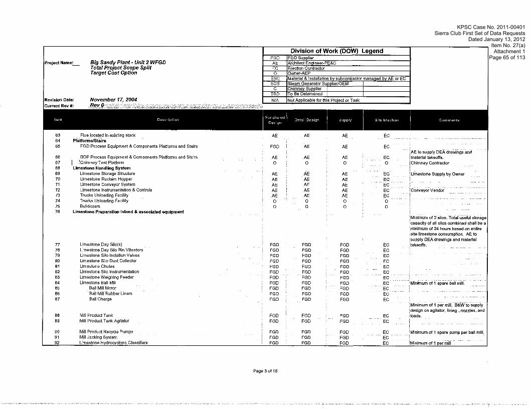
Big Sandy Plant - Unit 2 WFGD Total Project Scope Split Target Cost Option
Equipment & Components Platforms and Stalrs 'AE to supply DEA drawlngs and
BOP Process Equipment & Components Platforms and Stars matenal takeoffs 67 1 / ~h tmney ~ e s t Platform 'Ch~mney Contractor 68 Limestone Handling System
Ltrnestone Storage Structure Llmestone Reclalm Hopper Llrnestone Conveyor System Llmestone Instrumentatlon & Controls Trucks Unloadlng Faclllty Trucks Unloadlng Facll~ty
76 Limestone Preparation Island 8 associated equipment 'M~nlmurn of 2 sllos Total useful storage capauty of all sllos combined shall be a
Limestone Day S~lo(s) L~mestone Day Sllo Bin V~brators Lirnestone S~lo lsolatlon Valves Llmestone Sllo Dust Collector Llmestone Chutes Lirnestone Silo lnstrumentatlon Limestone We~ghing Feeder Limestone Ball Mill Minimum of 1 spare ball mill.
Bail M~l l Motor Bail Mill Rubber L~ners
Minimum of 1 per m~ l l B&W to supply
Mlli Product Tank M~l l Product Tank Agitator
Mtnimum of 1 spare pump per ball mill.
Page 3 of 15
KPSC Case No. 2011-00401Sierra Club First Set of Data Requests
Dated January 13, 2012Item No. 27(a)Attachment 1
Page 65 of 113
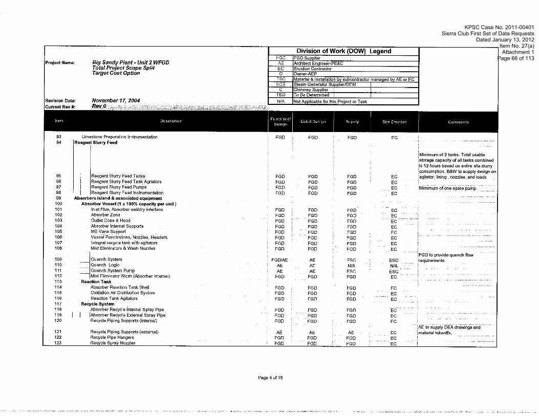
Big Sandy Plant - Unit 2 WFGD Total Project Scope Split Target Cost Option
urn of 2 tanks Total usable rage capauty of all tanks wmbined 12 hours based on entlre slte slurry
Reagent Slurry Feed Tanks 96 1 I IReagent Slurry Feed Tank Ag~tators 97 1 I IReagent Slurry Feed Pumps 98 1 I ]Reagent Slurry Feed lnstrurnentatlon
Absorber Vessel (1 x 100% capacity per unit ) Inlet Flue, Absorber wetldry Interface Absorber Zone Outlet Cone & Hood Absorber Internal Supports ME Vane Support Vessel Penetrations, Nozzles, Headers Integral recycle tank wth ag~tators Mlst Ellrnlnators &Wash Nozzles
Absorber React~on Tank Shell Oxldat~on Air D~str~but~on System Reactlon Tank Ag~tators
Recycle System Absorber Recycle Internal Spray Plpe
Recycle Plplng Supports (Internal)
Page 4 of 15
KPSC Case No. 2011-00401Sierra Club First Set of Data Requests
Dated January 13, 2012Item No. 27(a)Attachment 1
Page 66 of 113

Big Sandy Plant - Unit 2 WFGD Total Project Scope Split Target Cost Option
Recycle Pump Recycle Pump Gearbox I Accessories Recycle Pump Motor
Oxidation Air Supply Ox~datlon Alr Blowers Ox~datlon Alr Blower Motors Oxldatlon Alr Blower Nolse Enclosure Oxldatlon Alr lnlet Fllter Oxldatlon Alr lnlet Fllter Sllencer Oxldatlon Air Control Panel Ox~dat~on Alr Saturation Nozzle
ndor to supply des~gn on agitator, mergency Storage Tank
ergency Storage Tank Ag~tator(s) ergency Storage Tank Return Pumps ne spare per tank GDlAbsorber lnstrumentatlon Island B associated equipment
Absorber Bleed Pump
Hydrocyclone Classifier Cluster
Secondary Dewater~ng
Hydroclone Feed Tank Hydroclone Feed Tank Agltator
Page 5 of 15
KPSC Case No. 2011-00401Sierra Club First Set of Data Requests
Dated January 13, 2012Item No. 27(a)Attachment 1
Page 67 of 113

Big Sandy Plant - Unit 2 WFGD Total Project Scope Split Target Cost Option
Honzontal Vacuum Belt Fllter lnlmum of 1 spare vacuum belt filter Vacuum Filter Auxiliaries
lnlmum of 1 per vacuum belt filter cnlmum of 1 per vacuum belt filter tnimum of 1 per vacuum belt filter
Seal Water Tank lnlmum of 1 per vacuum belt filter Cake Wash Pump lnlmum of 1 per vacuum belt filter Cloth Wash Tank lnlmum of 1 per vacuum belt filter Cloth Wash Pump lnlmum of 1 per vacuum belt filter
Reclaim Water Storage 8 Return lnimum of 2 tanks Total useful orage capaaty of all tanks wmblned 8 hours based on entire scte redam
ater rate FGD vendor to supply slgn of agctator, llnlng , nozzles, and
Reclaim Water Tank Redalm Water Tank Ag~tator
Redalm Water Pump lnlmum of 1 spare pump Dewaterlng System Instrumentation
161 Gypsum Handling Belt Filter Discharge Conveyor Cake Transfer Conveyor Product Cake Stackout 8 Storage
Gypsum Storage Structure Gypsum Stacker
andl~ng Instrumentatcon
Page 6 of 15
KPSC Case No. 2011-00401Sierra Club First Set of Data Requests
Dated January 13, 2012Item No. 27(a)Attachment 1
Page 68 of 113

Big Sandy Plant - Unit 2 WFGD Total Project Scope Split Target Cost Option
Sewlce Water Tank
Make Up Water Pump Make Up Water instrumentation
Mist Eliminator Wash
Mlst Ellmlnator Wash Pumps M~st El~mlnator Wash Pump lnstrumentatlon
/Reagent Preparatlon Area Sump IReagent Preparatlon Area Trench IReagent Preparation Area Grating )Reagent Preparatlon Area Sump Agltator IReagent Preparatlon Area Sump Pump
188 1 1 /Reagent Preparation Area Sump Agitator li Pump Supports IReagent Preparation Area Sump System instrumentatlon
Absorber Area Sump System (Absorbers share common sump.) Absorber Area Sump Absorber Area Trench Absorber Area Grating
Absorber Area Sump Agltator 8 Pumps Supports Absorber Area Sump System lnstrumentatlon
Dewatering Area Sump System Dewaterlng Area Sump Dewatering Area Trench
Page 7 of 15
KPSC Case No. 2011-00401Sierra Club First Set of Data Requests
Dated January 13, 2012Item No. 27(a)Attachment 1
Page 69 of 113

Big Sandy Plant - Unit 2 WFGD Total Project Scope Split Target Cost Option
Dewaterlng Area Sump Agltator & Pumps Supports Dewaterlng Area Sump System lnstrumentat~on
Maintenance Tank Area Sump System Malntenance Tank Area Sump Malntenance Tank Area Trench Malntenance Tank Area Gratlng Malntenance Tank Area Sump Agltator Malntenance Tank Area Sump Pump
Malntenance Tank Area Sump Agltator & Pumps Supports Malntenance Tank Area Sump System lnstrumentat~on
ID Fans Motors Fan lsolatlon Dampers lnstrumentat~on
220 WFGD Waste Water WFGD Waste Water Treatment System
222 Heating, Ventilation and Air Conditioning (HVAC) FGD Process Equlpment FGD Process Island Bulldlngs BOP Process Equlpment
FGD Process Equlpment BOP Process Equlpment
229 Lifting 8 Handling Equipment
Monorall (for FGD Process Equlpment)
Page 8 of 15
KPSC Case No. 2011-00401Sierra Club First Set of Data Requests
Dated January 13, 2012Item No. 27(a)Attachment 1
Page 70 of 113

Big Sandy Plant - Unit 2 WFGD Total Project Scope Splii Target Cost Option
FGD Process Plplng
Slngle Supply Polnt by AE Small bore
Seal Water Limestone Prep Area Sump Transfer Absorber Area Sump Transfer Dewaterlng Area Sump Transfer Flush Water
F~rewater loop mods, hydrants, hose stat~ons
Potable Water
Sanltary Water
Process Dram and Vents (In FGD Island) Process Dram and Vents (In BOP)
Sewlce & Instrument Air (W~thln Islands) Closed Cycle Coollng Water (Wlthln Island)
trument Dlagrams
Page 9 of 15
KPSC Case No. 2011-00401Sierra Club First Set of Data Requests
Dated January 13, 2012Item No. 27(a)Attachment 1
Page 71 of 113

Revision Date:
Project Name:- Big Sandy Plant - Unit 2 WFGD Total Project Scope Split Taraet Cost O ~ t i 0 n -
November 17. 2004
Division of Work (DOW) Legend
I N/A l ~ n t Annlicahle for this Prniart nr Tark I
FGD AE EC 0 . . . . . . . . . - .
I 264
FGD Piping Spec FGD
FGD Supplier Architect Engineer-PEBC Erection Contractor Owner-AEP
ESC SGS
C TBD
265 FGD Equipment lnsulat~on I ::: BOP CoatingIPaint Spec BOP Piping and Instrument Diagrams
Material & Installation by subcontractor managed by AE or EC Steam Generator SupplierIOEM I Chimney Supplier I To Be Determined I I
268 BOP Piping isometric Drawings 269 BOP Equipment List 270 BOP Piping Line Llst 271 BOP Valve List 272 BOP Piplng Spec 273 lnsulation 8 Lagging Material 274 FGD Equipment Insulation
275 Fluework Insulation ~ncludlng booster fans I ::: FGD P~plng lnsulation FGD Buildings & Enclosures lnsulat~on
FGD AE AE
FGD
AE FGD AE
FGD NIA
FGD FGD AE NIA AE NIA AE AE AE AE AE
FGD
NIA NIA NIA NIA NIA
ESC
NIA i /As Required on skid mounted
ESC 'If required IAE to supply DEA drawings and
AE ESC FGD ESC AE ESC I
BOP Equ~pment lnsulat~on BOP Plplng lnsulatlon BOP Bulld~ngs &Enclosures lnsulat~on
281 1 8 C Drawings 8 Documents FGD Analog Log~c Diagrams FGD Dlgltal Log~c D~agrams FGD lnstrument Data Sheets FGD lnstrument Equ~pment Specifications FGD lnstrument lnstallat~on Speclficat~on FGD lnstrument Locat~on Drawlngs FGD lnstrument lnstallat~on Detalis FGD lnstrument and DCS 110 L~sts BOP Analog Loglc D~agrams BOP D~g~ta l Log~c D~agrams
Page 10 of 15
KPSC Case No. 2011-00401Sierra Club First Set of Data Requests
Dated January 13, 2012Item No. 27(a)Attachment 1
Page 72 of 113

Big Sandy Plant - Unit 2 WFGD Total Project Scope Split Target Cost Option
Acceptance Testlng
307 Electrical Design Drawings 8 Documents Slngie Llne D~agrams Elementary D~agrams lnterconnectlon Dlagrams Electr~callElectron~cs Room Layout Electr~cai Load Llst put from FGD OEM Power System Stud~es (SKM)
314 Power Distribution Equipment Un~t Aux Transformer iso-Phase Bus B. Modlficat~ons Non-Seg Bus and Modtficat~ons Medlum Voltage Cable Bus Substat~on I Load Center Transformers
Power Distribution Panels FGD Process Equipment Variable Frequency Drlves (480V) BOP Process Equipment Variable Frequency Drtves (480V)
327 Transmission o f Bulk Power t o FGD Substation Existing substation modlflcations
New Transmlsslon Llne New FGD Substation HV
331 Power Sources Equipment
334 Motors (Provided with Equipment)
Page 11 of 15
KPSC Case No. 2011-00401Sierra Club First Set of Data Requests
Dated January 13, 2012Item No. 27(a)Attachment 1
Page 73 of 113
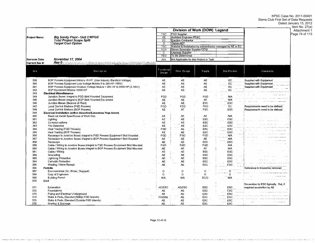
Big Sandy Plant - Unit 2 WFGD Total Project Scope Split Target Cost Option
Junction Boxes Integral to FGD Skid Mounted Equipment Junction Boxes integral to BOP Skid Mounted Equipment Junction Boxes (Balance of Plant) Local Control Stations (FGD Process) Local Control Stations (BOP Process)
349 Electrical Installation (within AbsorberIL~mestone Prep Areas) Electrical Install SpeclSwpe of Work Doc
Comrnunlcations F~re Detection Heat Traclng (FGD Process) Heat Traclng (BOP Process) Raceways to Junction Boxes Integral to FGD Process Equipment Sk~d Mounted
Lightning Protection Cathodlc Protection Weldlng I Maint Recept
Env~ronmental ( k r , Water, Disposal) Corp of Engineers Bu~ld~ng Permlt
370 Civil
equlred excavatton by AE
Page 12 of 15
KPSC Case No. 2011-00401Sierra Club First Set of Data Requests
Dated January 13, 2012Item No. 27(a)Attachment 1
Page 74 of 113

Big Sandy Plant - Unit 2 WFGD Total Project Scope Split Target Cost Option
ction Serv~ces
Englneerlng Support (HO) Slte Support Sewlces (Slte) Temporary Utlllbes & Sewlces Unloading and S~te Storage Craneage I Llfllng Equ~pment Office Trallers Office Equlpment
Safety Equipment S~te Computer Sewlces Mob~llzatlonlDemob~l~zat~on Costs Slte Constructlon Sewlces Subcontractor
397 Buildings i3 Structures FGD Process Island Bulldlngs (Architectural)
M~scellaneous Bu~ldlngs (Pre-eng~neered) Warehouselshops
401 CommissioninglStartup Comm~ss~onlng FGD Technical Support
403 1 l~omm~ss~onlng BOP Techn~cal Support Cornrn~ss~on~ng & Startup Standby Labor
KPSC Case No. 2011-00401Sierra Club First Set of Data Requests
Dated January 13, 2012Item No. 27(a)Attachment 1
Page 75 of 113

Big Sandy Plant - Unit 2 WFGD Total Project Scope Split Target Cost Option
rnance Guarantees for FGD Process Equlprnent As expressly stated in the proposal
Customs Fees I Dut~es
Project Related Travel Personnel Relocat~on lnter~rn Llv~ng Expenses
425 Turnover Documentation OBM Manual
Spare Parts L~st Each h ~ s own Quoted as an opeon for
Cornm~ssion~ng Manual 432 Taxes
Page 14 of 15
KPSC Case No. 2011-00401Sierra Club First Set of Data Requests
Dated January 13, 2012Item No. 27(a)Attachment 1
Page 76 of 113

KPSC Case No. 2011-00401Sierra Club First Set of Data Requests
Dated January 13, 2012Item No. 27(a)Attachment 1
Page 77 of 113

PARSONS EfiC
Appendix A
WFGD Material Balance Tables and Process Flow Diagrams
Big Sandy Unit 2
KPSC Case No. 2011-00401Sierra Club First Set of Data Requests
Dated January 13, 2012Item No. 27(a)Attachment 1
Page 78 of 113

FORM E P j J 8100
Big Sandy Unit 2 - WFGD Gas Path Material Balance - 100% MCR Load Condition 1 Strrrsm I 1 I 2 I 3 I 4 I 5 I 6 I 7 I 8 I 9 I 10
1
-. --
Component Lblhr
A
Jay Whte
B. Graeffe
1011912004
Reson:
O&imbr
Reviewer:
Date:
Ee=
CALCULATION SHEET
Ar
C02
HCL
UE
2 0
Jay Whle
B. Graeffe
121612004
CLIENT NAME: AEP
PROJECT NAME: Big Sandy Unit 2
SUBJECT: Boiler and FGD Material Balance Estimate
WORKSHEET: Material Balance Re~ort Sheets
Coal Input
Mass
Coal
Ash
Total Solids Flow
58,747
826.412
674
Total Stream Mass Flow
3
-
ID Fan Suction
Mass Mole
654,924
0
654.924
Gas Flow, ACFM
Mol. Wt.
Temp, deg F
Pressure, psia
- --
AEBS-2-DC-042-5-001-RO xls THIS IS A DESIGN RECORD
JOB NUMBER:
53762301
CALCULATION NUMBER:
AEBS-2-DC-042-5-001
1.471
18.778
18
654.924
CaS04 2H20
HZ0
MgC03
A l k a l ~ lnerts
Flyash
TDS
Total Flow
Flow, gpm
Spec~fic G r a v ~ t y
Cl , ppmw
TSS. %
TDS. %
PAGE 1 OF 1
0
965
965
1,708,092
32 1
13.42
ID Fan Discharge
58.747
826.412
674
4 858.956
103 338
456 706
1,789
5,946
3 337
11 754
585,575
1031
113
12,000
20 00
2 51
Mass
0
965
965
29.6240
Mok
Flue Gas to FGD Absorber
1.471
18.778
18
4.858.956
10 334
361 000
1150
3 865
2,670
9 291
388.237
751
1 03
12.000
4 87
2 51
Flue Gas Entering WESP
Mass Mob Mass
0
1,930
1,930
1,592,796
349
14.88
Mole
117.493
1.652.824
1.347
<a
9,717,911
93,004
95 705
619
2,081
687
2 463
196.337
280
1 40
12,000
50 00
2 51
Flue Gas Entering Stack
Mass Mole
0
0
488
29.6240
2.941
37.556
37
1
0
0
488
10.351.414
3,053
106 646
340
1 142
789
2.745
114.988
222
1 03
12,000
4 87
2 51
Oxidation Air Inlet
Mass Mok
3.189.465
349
14.86
118.487
1,678,098
0
n
10.351.414
0
147 170
1.893
3,154
0
26
210.280
347
121
19
30 00
0 02
Oxidation Air Blower Outlet
Mass Mole
29.6240
2.966
38.130
0
o
77,164
9.141
696,952
822
2 785
1.894
9,052
721.317
1429
101
2638
0 44
0 56
Ox Air with Quench Water
Mass Mole
2,644,704
128
14.41
Oxidation Air Quench Vllatel
Mass Mole
118.487
1,878,098
0
n
77,164
7 281
254 354
810
2.723
1,881
6.546
274,250
529
1 03
12,000
4 87
2 51
28.5575
2.966
38.130
0
o
79.560
0
3 154
1893
3 154
0
0
66,238
n la
n la
n la
95 24
nla
2.395
2,648,024
128
14.39
994
0
0
o
0
147.170
1,893
3.154
0
26
210.280
347
1 21
19
30 00
0 02
28.5575
0
144 016
0
0
0
26
144.042
291
0 99
19
0 00
0 02
25
0
0
o
17,602
70
14.39
994
0
0
o
28.8434
25
0
0
o
11,135
251
30.54
994
0
0
o
28.8434
25
0
0
0
9,592
121
30.39
0
0
0
0
0
0
0
o
28.3307
da
70
50
18.0153
KPSC Case No. 2011-00401Sierra Club First Set of Data Requests
Dated January 13, 2012Item No. 27(a)Attachment 1
Page 79 of 113

FORM EPJJ BlOO
I PARSONS E=C
CALCULATION SHEET
I CLIENT NAME:
PROJECT NAME:
AEP
Big Sandy Unit 2
I - .
SUBJECT: Boiler and FGD Material Balance Estimate
WORKSHEET: Material Balance R e ~ o r t Sheets i Reviewer:
Date:
I I 2 3 I JOB NUMBER: I
B. Graeffe B. Graeffe i CALCULATION NUMBER:
1011812004 12!612004 AEBS-2-DC-042-5-001
Bia Sandv Unit 2 - WFGD Secondarv Dewaterina Material Balance - 100% MCR Load Condition I Stream I 41 I 42 I 43 I 44 I 45 I 46 I 50 I 51 I -. --
Component lblhr I Vacuum Belt Filter Feed I vaFuum "Iter Cake I Cake to ktackout Conveyor1 Vacuum Belt Filter Filtrate I Filter Cake Wash Water 1 iake-up I Water 1 Discharge Tank Make-up Tank
Water to Mist Eliminator
CaC03
CaS03:1/2H20
CaS04:2H20
HZ0
MgC03
Alkali lnerts
Flyash
Tnc
Flow. gprn
Specific Gravity
CK, pprnw
TSS, %
TDS, %
, -- Total Flow
THIS IS A DESIGN RECORD
186,337 106,895 105.895 111.570 22.127 335.497 711,983 207,921
KPSC Case No. 2011-00401Sierra Club First Set of Data Requests
Dated January 13, 2012Item No. 27(a)Attachment 1
Page 80 of 113
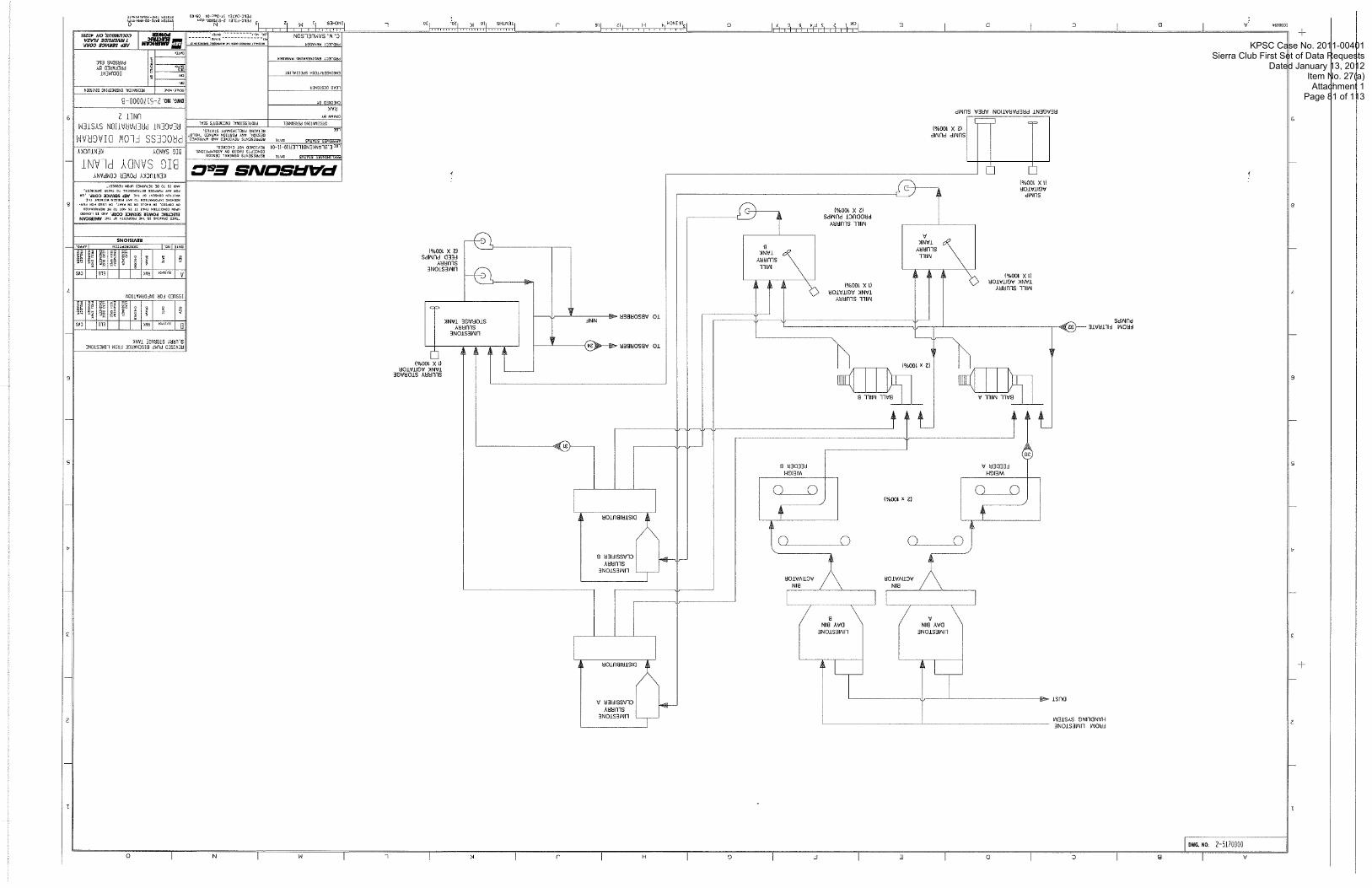
1 r o 3 a I ,.ow .,,, sum no 'Snswni03 ::::I:;;;::; .:::::::::...
r n d 3u1sn3Nn 1 NOSl3nWVS ' A '3
11311VNIll 133POld
'3110
393 SNOSIVd 8381NYU 9Ni1133N1'1N3 133COXd
< ihd"S A0 03IVd3Id IN3Wn300
330
:"> ISilVIJ3dS H531/1133NI.)N3
KPSC Case No. 2011-00401Sierra Club First Set of Data Requests
Dated January 13, 2012Item No. 27(a)Attachment 1
Page 81 of 113

AMMONIA MIXTURE
MAGNESIUM HYDROXIDE INJECTION
AMMONIA MIXTURE
FUTURE MERCURY i FLUE GAS
CONTROL BAGHOUSE TO ABSORBER
1 1 1 I -- FLYASH bTO ASH POND
KENTUCKY POWER COMPANY
zSoNS DATE REPREEENTP GENLR~L Es OLEIGN BIG SANDY PLANT
COUCE?IQ BISED ON ASSUIIPIIONS. BIG SANDY to~E.BLRNKENBILLERIO-II-O1 ??EViiWiD r;oi CHECKEO.
REPRESENTS R E V I E l i D AN0 APPROVE\ ,,,,,.. .,, , ,,,,,, ,,,,,, . ,,,, PROCESS FLOW D I A G R A M RETAIN$ PRELIflINARI STATUS.
ORlGINAIlBG PtRSDNMi PRoFEsSIOmL ~IIGIII~ER~S SEAL COMBUSTION AIR AND FUEL GAS
+ IGSOIPI
RAK CHECKED 81
LLAD DESIGNER
<"I ENGINEEII/TECH SPLCIAI IST
OES DOCUHENT
ru.v; PREPARED BY
3 PARSONS ELC O I T E ;
DWG. NO. 2-5170001-A SCALP 0s MJlZ IECHABICAL EhCIKERiNG DIVISION
KPSC Case No. 2011-00401Sierra Club First Set of Data Requests
Dated January 13, 2012Item No. 27(a)Attachment 1
Page 82 of 113

FILTERED RIVER ----
WATER
FILTER CAKE WASH WATER
SERVICE WATER TANK
M A K E U P WATER TO RECLAIM C ,
V MAKE-UP TO MILL 4 BOP SERVICE
WATER PUMPS 12 X 100%1
FGD SERVICE WATER I2 X 100%) PUMPS
TO ABSORBER MIST ELIMINATOR
TO OXIDATION AIR OUENCH WATER
~~ - ~ ......,
, 11 IND 1s 10 BE PGTMNEO UPON DiOUisi. /I I KENTUCKY POWER COMPANY
BIG SANDY PLANT BIG SANDY KENTUCKY
PROCESS FLOW D I A G R A M MAKE-UP WATER SYSTEM
IINTT 7
I~DWG. NO. 2-5170002-A IC*LI ;MK l o U W 1 C l l ENGlKLRlRG OlViSiON
DOCUMENT
PARSONS ELC
DA,*
KPSC Case No. 2011-00401Sierra Club First Set of Data Requests
Dated January 13, 2012Item No. 27(a)Attachment 1
Page 83 of 113

KPSC Case No. 2011-00401Sierra Club First Set of Data Requests
Dated January 13, 2012Item No. 27(a)Attachment 1
Page 84 of 113

HYDROCYCLONE UNDERFLOW VACUUM BELT FILTERS
(2 X 100%)
VACUUM BELT VACUUM BELT
J j OFF SPEC GYPSUM
FLUSHING WATER PUMP
GYPSUM STORAGE
AODED OEVATERING AREA SUMP I1 8 ~ I ~ , Z V O . I R A K ~ 1 1 1 ELO 1 1 CYS
ISSUED FOR INFORMATION
KENTUCKY POWER COMPANY -
L-SoNz LDEE.BLANKENBILLERIO-11-04 REPRESENTS CONCEPTS REvlEvro NO? BASED GENERAL c~acnio. ON A25UMPIIONS. OESIGN
BIG BIG SANDY SANDY PLANT -
9
I C A L T . M S E C H I N I C A I ENGILEIRING (IIYISION
DR.
ENGINEEI1,TECH SPECIALIST Oil
supr: Y % PREPARED PARSONS ELL BY
O I T t i
A P P R O Y r p OLTE REPRISENIB XEYIEYLD AND l i P P R O V E 0
LOE D,,r,N. ,,,,,,, ..,,,, .,,,,- RETAINS PRELIMINARY STAiUS.
KENTUCKY
P R O C E S S FLOW D I A G R A M DEWATERING SYSTEM
U N I T 2
DWG. NO. 2-5170004-0
O R I G I N A I I N G PtRSObNEL ORAXW BY
RAK CHECK0 BY
9 PROFESSIONM ENGINEER'S SEAL --
KPSC Case No. 2011-00401Sierra Club First Set of Data Requests
Dated January 13, 2012Item No. 27(a)Attachment 1
Page 85 of 113

PARSONS EslC
Appendix B
Plot Plans and General Arrangement Drawings
Big Sandy Unit 2
KPSC Case No. 2011-00401Sierra Club First Set of Data Requests
Dated January 13, 2012Item No. 27(a)Attachment 1
Page 86 of 113

KPSC Case No. 2011-00401Sierra Club First Set of Data Requests
Dated January 13, 2012Item No. 27(a)Attachment 1
Page 87 of 113

KPSC Case No. 2011-00401Sierra Club First Set of Data Requests
Dated January 13, 2012Item No. 27(a)Attachment 1
Page 88 of 113
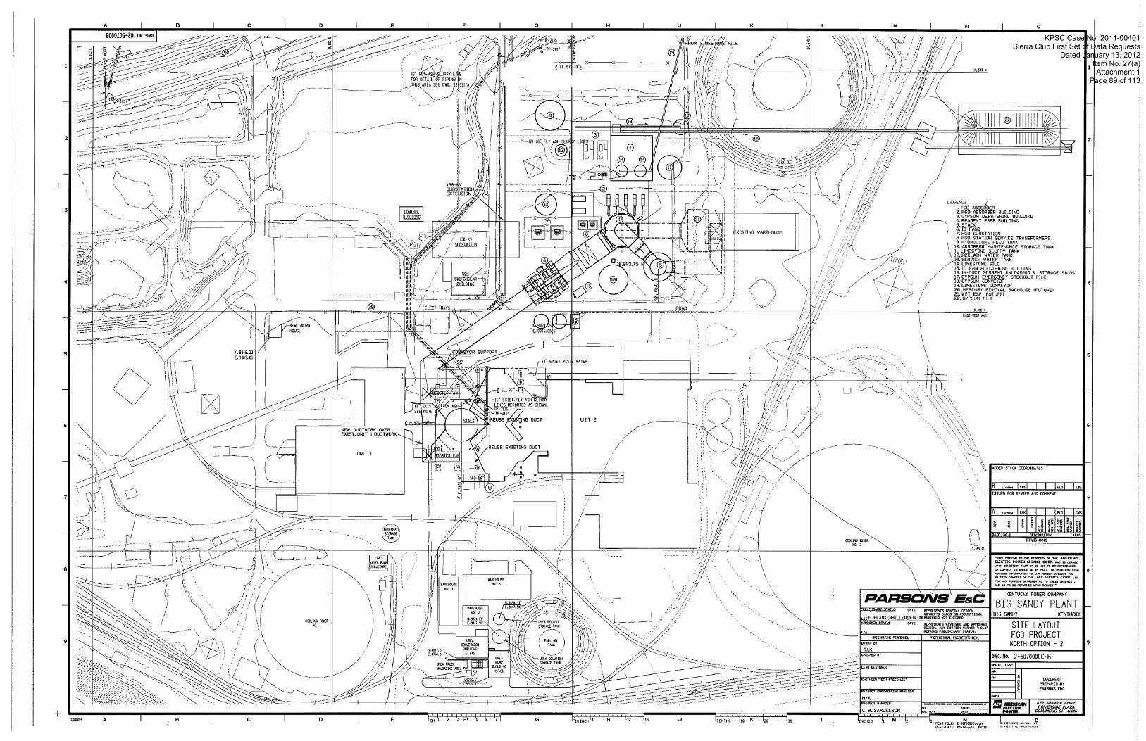
KPSC Case No. 2011-00401Sierra Club First Set of Data Requests
Dated January 13, 2012Item No. 27(a)Attachment 1
Page 89 of 113

KPSC Case No. 2011-00401Sierra Club First Set of Data Requests
Dated January 13, 2012Item No. 27(a)Attachment 1
Page 90 of 113

KPSC Case No. 2011-00401Sierra Club First Set of Data Requests
Dated January 13, 2012Item No. 27(a)Attachment 1
Page 91 of 113

KPSC Case No. 2011-00401Sierra Club First Set of Data Requests
Dated January 13, 2012Item No. 27(a)Attachment 1
Page 92 of 113

KPSC Case No. 2011-00401Sierra Club First Set of Data Requests
Dated January 13, 2012Item No. 27(a)Attachment 1
Page 93 of 113

KPSC Case No. 2011-00401Sierra Club First Set of Data Requests
Dated January 13, 2012Item No. 27(a)Attachment 1
Page 94 of 113

KPSC Case No. 2011-00401Sierra Club First Set of Data Requests
Dated January 13, 2012Item No. 27(a)Attachment 1
Page 95 of 113

LEGEND:
1 ABSORBER 2 ABSORBER RECYCLE PUMP 3 ABSORBER RECYCLE PUMP DISCHARGE RISER 4 ABSORBER BLEED PUMP 5 ABSORBER AREA SUMP 6 OXIDATION AIR COMPRESSOR 7 HYDROCLONE FEED PUMP 8 AIR COMPRESSOR 9 AIR RECEIVER 10 INSTRUMENT AIR DRYER 11 FLOOR TRENCH I2 STAIRTOWER 13 ELEVATOR 14 EMERGENCY EYE & FACE WASH
FGD SERVICE TRANSFORMERS
PLAN - GROUND FLOOR
SCALE IN FEET
KPSC Case No. 2011-00401Sierra Club First Set of Data Requests
Dated January 13, 2012Item No. 27(a)Attachment 1
Page 96 of 113

! I ! !
ROLL-UP DOOR ! / ( IT-0 ' WIDE)
REAGENT! SLURRY STORAGE! TkNK
PLAN - GROUND FLOOR REAGENT PREPARATION AREA
KPSC Case No. 2011-00401Sierra Club First Set of Data Requests
Dated January 13, 2012Item No. 27(a)Attachment 1
Page 97 of 113

KPSC Case No. 2011-00401Sierra Club First Set of Data Requests
Dated January 13, 2012Item No. 27(a)Attachment 1
Page 98 of 113
PARSONS EGC
Appendix C
Process Equipment List
Big Sandy Unit 2
KPSC Case No. 2011-00401Sierra Club First Set of Data Requests
Dated January 13, 2012Item No. 27(a)Attachment 1
Page 99 of 113

Big Sandy Unit 2 Process Equipment List
KPSC Case No. 2011-00401Sierra Club First Set of Data Requests
Dated January 13, 2012Item No. 27(a)Attachment 1
Page 100 of 113

FGD Bleed Pumps Quantity Capacity per Pump Pump motor size
Absorber Agitators Quantity Size
Oxidation Air Blowers Quantity Capacity per Blower Blower motor size
Absorber Maintenance Tank Quantity Capacity Diameter x height Tank Mixer
Absorber Maintenance Tank Return Pumps
Quantity Capacity per Pump Pump motor size
Sump Pit Quantity Capacity
Sump Pump Quantity Capacity Pump motor size
Sump Agitator Quantity Motor size
Service Air Compressors Quantity Capacity Motor size
Instrument Air Dryer Quantity Capacity
Service Air Receiver Instrument Air Receiver
gpm hp
hp
Acfm h~
gal ft hp
gpm hp
ft x ft x ft
gpm hp
h~
scfm hp
scfm
2 (1 OP, 1 s ~ ) 2,130
60
8 75
2 (1 op, 1 sp) 19,600 2,100
1 1,400,000 56 x 73
40
2 (1 OP, 1 SP) 3,000 110
1 l o x l o x 10
2 (1 OP, 1 SP) 500 75
1 20
2 (1 op, 1 sp) 300 100
2 (1 OP, 1 SP) 300
1 1
KPSC Case No. 2011-00401Sierra Club First Set of Data Requests
Dated January 13, 2012Item No. 27(a)Attachment 1
Page 101 of 113

1 300 100
1 300 20
1 -
300 20
1 300 120
1 300 20
Limestone Handling Stacking Conveyor
Quantity Capacity Motor size
Reclaim Hopper 1 Hopper Activator
Quantity Capacity Motor size
Reclaim Belt Feeder Quantity - - -
Capacity Motor size
Reclaim Belt Conveyor Quantity Capacity Motor size
Conveyor to Day Bin Quantity Capacity Motor size
Todhr
h p
Tonlhr hp
-
Tonlhr h~
Todhr
h p
Todhr hp
KPSC Case No. 2011-00401Sierra Club First Set of Data Requests
Dated January 13, 2012Item No. 27(a)Attachment 1
Page 102 of 113

2 (1 op, 1 sp) 40
2,000
2 8 6 11 42 14
2 (1 Op, ISP) 5
2 (1 OP, 1 s ~ ) 12 6
2 (1 op, lsp) 40 10
2 (1 OP, lsp) 5
9 x 12 8
2 ( 1 Op, ISP) 900 100
2 (1 OP, lsp) 900
1 4
25 x 32 40
Limestone Preparation Limestone Ball Mills
Quantity Capacity per Mill Mill motor size
Limestone Day Silos Quantity Capacity per silo Height Top Cone Height Bottom Cone Total Height Diameter
Day Silo Bin Vent Filter Quantity Filter Fan Size
Day Silo Bin Activator Quantity Diameter Motor size
LS Weigh Belt Feeder Quantity Capacity per mill Motor size
Mill Slurry Tanks Quantity Capacity I Tank Diameter x height Tank Mixer
Mill Slurry Pumps Quantity Capacity per Pump Pump motor size
Limestone Slurry Classifier Quantity Capacity
LS Slurry Storage Tanks Quantity Capacity I Tank Diameter x height Tank Mixer
Tonslhr hp
hours ft ft ft ft
h p
ft hp
Tonslhr h~
minutes ft hp
@m hp
@m
hours ft hp
KPSC Case No. 2011-00401Sierra Club First Set of Data Requests
Dated January 13, 2012Item No. 27(a)Attachment 1
Page 103 of 113

Limestone Preparation (continued) LS Slurry Feed Pumps
Quantity Capacity per Pump Pump motor size
Sump Pit Quantity Capacity
Sump Pump Quantity Capacity Pump motor size
Sump Agitator Quantity Motor size
gpm hp
ft x ft x ft
gPm HP
Hp
2 (1 OP, lsp) 790 50
1 l o x l o x 10
2 (1 op, 1 sp) 150 50
1 20
KPSC Case No. 2011-00401Sierra Club First Set of Data Requests
Dated January 13, 2012Item No. 27(a)Attachment 1
Page 104 of 113

Gypsum Dewatering Hydrocyclone Feed Pumps
Quantity Capacity per Pump Pump motor size
Hydrocyclones Quantity Capacity per HC
Hydrocyclone Overflow Head Tank Quantity Diameter x height Tank Mixer Size
Purge Pumps Quantity Capacity per Pump Pump motor size
Filtrate Tanks Quantity Capacity per Tank Diameter x height Tank Mixer Size
Filtrate Return Pumps Quantity Capacity per Pump Pump motor size
Gypsum Belt Filters Quantity Capacity per Filter Belt Drive motor size
Vacuum Pumps Quantity Pump Motor size
gpm
ft hp
hp
hours ft hp
gpm hp
T o n s h h~
hp
2 (1 OP, 1 SP) 1,200 120
2 (1 OP, 1 sp) 1,200
1 9 x 10
5
2 (1 op, 1 sp) 250 30
1 8
43 x 56 30
2 (1 op, lsp) 2,000 150
2 (1 OP, lsp) 55 10
2 (1 OP, ISP) 600
KPSC Case No. 2011-00401Sierra Club First Set of Data Requests
Dated January 13, 2012Item No. 27(a)Attachment 1
Page 105 of 113

KPSC Case No. 2011-00401Sierra Club First Set of Data Requests
Dated January 13, 2012Item No. 27(a)Attachment 1
Page 106 of 113

Makeup Water Makeup Water Tank
Quantity Capacity per Tank Diameter x height
FGD Service Water Pumps Quantity Capacity per Pump Pump motor size
BOP Service Water Pumps Quantity Capacity per Pump Pump motor size
hours ft
gpm hp
@m h p
1 1
25 x 32
2 (1 Op, 1 SP) 500 70
2 (1 op, 1 sp) 1,500 150
KPSC Case No. 2011-00401Sierra Club First Set of Data Requests
Dated January 13, 2012Item No. 27(a)Attachment 1
Page 107 of 113

PARSONS EfiC
Appendix D
Conceptual Electrical One Line Diagram and Conceptual Electrical Load List
Big Sandy Unit 2
KPSC Case No. 2011-00401Sierra Club First Set of Data Requests
Dated January 13, 2012Item No. 27(a)Attachment 1
Page 108 of 113

KPSC Case No. 2011-00401Sierra Club First Set of Data Requests
Dated January 13, 2012Item No. 27(a)Attachment 1
Page 109 of 113

BIG SANDY UNlT 2 FGD CONCEPTUAL ELECTRICAL LOAD LIST
CnNNFCTFn l nAn9
AEBS-2-LI-023-0001 -B Page 1 of 4
BUS 13.8KV FGD BUS A
4.16KV FGD BUS A
480V FGD BUS A
480V FGD COMMON BUS A
480V COMMON LOAD MCC 1
480V COMMON LOAD MCC 3
480V ABSORBER MCC A
LOAD ID FAN A
RECYCLEPPA RECYCLEPPB RECYCLEPPC OXIDATION AIR BLOWER A BALL MILL A DEWATERING VACUUM PP A
ABSORBER MAlNT TANK RETURN PP A GYP DEWATERING FILTRATE RETURN PP A RAW WATER PP A BOP SERVICE WATER PP A HYDROCYCLONE FEED PP A
FGD BLDG EXHAUST FANS
FGD BLDG ELEVATOR RM EXHAUST FAN DCSIBATT ROOM AJC UNIT FEED #1 FGD BLDG UNIT HEATERS
SUBSTA XFMR PP FEED #1 SUBSTA UTILITIES FEED CHIMNEY AOL CEMS FEED #1 CHIMNEY ELEVATOR FGD POTABLE WATER BOOSTER PP 1 FGD BLDG INSTANT HOT WATER HTR 1201208V DISTRIBUTION PANEL XFMR
LIMESTONE PREP BLDG UNIT HEATERS LIMESTONE PREP BLDG ROOF EXH FANS 1201208V DISTRIBUTION PANEL XFMR
FGD BLEED PP A ABSORBER REACTION TK AGITATOR A ABSORBER REACTION TK AGITATOR B ABSORBER REACTION TK AGITATOR C ABSORBER REACTION TK AGITATOR D ABSORBER AREA SUMP PP A ABSORBER AREA SUMP AGITATOR
HP 20,000
2,600 2,600 2,600 2,100 2,000 600
110 150 150 1 50 120
0.5
5
60 75 75 75 75 75 20
KVA
125 150 8
50
45
45
--....- w . KW
75
177
130
1 40
-w w-w-
AMPS
47
100
42
COMMENTS
Assumed possible load
No directly connected end loads
Mitchell = 10@ 10HP (1 4FLA ea); demand factor: 0.5. 70A total Big Sandy - use 213 of Mitchell value due to smaller FGD Building size. 47A total Value based on Mitchell Based on Mitchell. Assume this unit running; Common Load MCC 2 unit idle. Mitchell PPllPP2 = 14@ 10kW plus 26@ 15kW; demand factor: 0.5. 265kW total Big Sandy - use 213 of Mitchell value due to smaller FGD Building size. 177kW total Alternate to Common Load MCC 2 Feed #2 Value based on Mitchell assumption Value based on Mitchell Alternate to Common Load MCC 2 Feed #2 Value based on Mitchell Assumed load and value; based on Mitchell Assumed Battery Room eyewashlshower; based on Mitchell
Mitchell = 5@40kW; demand factor: 0.7. 140kW total. Big Sandy - use same as Mitchell Mitchell = 6@ 1 OHP(14FLA ea); demand factor: 0.5. 42A total. Big Sandy - use same as Mitchell
KPSC Case No. 2011-00401Sierra Club First Set of Data Requests
Dated January 13, 2012Item No. 27(a)Attachment 1
Page 110 of 113

BIG SANDY UNIT 2 FGD CONCEPTUAL ELECTRICAL LOAD LIST
CnNNFCTFn l n A n S
AEBS-2-LI-023-0001 -B Page 2 of 4
480V LIMESTONE PREP MCC A
480V GYPSUM DEWATER MCC A
480V ID FAN MCC A
13.8KV FGD BUS B
4.16KV FGD BUS B
SERVICE AIR COMPRESSOR A FGD SERVICE WATER PP A INSTRUMENT AIR DRYER SKID (HEATER) BATTERY CHARGER 1 UPS MAIN FEED 1201208V DISTRIBUTION PANEL XFMR
DAY BIN A VENT FILTER DAY BIN A ACTIVATOR ACTIVATOR A OUTPUT BELT FEEDER LIMESTONE WEIGH BELT FEEDER A MILL SLURRY TANK A MIXER MILL SLURRY PUMP A LIMESTONE SLURRY STORAGE TANK MIXER LIMESTONE SLURRY FEED PP A LIMESTONE PREP SUMP PUMP A LIMESTONE PREP SUMP AGITATOR 120l208V DISTRIBUTION PANEL XFMR
HYDROCYCLONE FEED TANK AGITATOR HYDROCYC OVERFLOW HEAD TANK MIXER HEAD TANK PURGE PP A VACUUM BELT FILTER A GYPSUM DEWATERING SUMP PP A CAKE WASH PP A VACUUM RECEIVER PP A 1201208V DISTRIBUTION PANEL XFMR
ID FAN A AUXILIARIES ID FAN A INLET ISOL DAMPER ID FAN A OUTLET ISOL DAMPER ID FAN A INLT IS0 DMPR SEAL AIR FAN 1201208V DISTRIBUTION PANEL XFMR
ID FAN B
RECYCLEPPD RECYCLEPPE RECYCLEPPF OXIDATION AIR BLOWER B BALL MILL B DEWATERING VACUUM PP B o-p
100 70
5 6 10 10 8
100 40 50 50 20
10 5
30 10 50 3 ?
75 60 100
20,000
2,600 2,600 2,600 2,100 2,000 600
40 30 45
45
45
45
--. .. .-- .
50
-- -----
200
Assumed name and HP rating
Assumption, based on Mitchell assumption
KPSC Case No. 2011-00401Sierra Club First Set of Data Requests
Dated January 13, 2012Item No. 27(a)Attachment 1
Page 111 of 113

BIG SANDY UNlT 2 FGD CONCEPTUAL ELECTRICAL LOAD LIST
CnNNFCTFn l n A n S
AEBS-2-LI-023-0001 -B Page 3 of 4
480V FGD BUS B
480V FGD COMMON BUS B
480V COMMON LOAD MCC 2
480V COMMON LOAD MCC 4
480V ABSORBER MCC B
480V LIMESTONE PREP MCC B
ABSORBER MAlNT TANK RETURN PP B GYP DEWATERING FILTRATE RETURN PP B RAW WATER PP B BOP SERVICE WATER PP B HYDROCYCLONE FEED PP B
OX AIR COMP & ELEC EQ RM FANS
DCSIBATT ROOM AIC UNIT FEED #2 FGD BLDG UNIT HTRS
FGD BLDG LOUVERS FGD BLDG ELEVATOR SUBSTA XFMR PP FEED #2 CHIMNEY GENERAL SERVICE PWR FEED CEMS FEED #2 FGD POTABLE WATER BOOSTER PP 2 1201208V DISTRIBUTION PANEL XFMR
GYPSUM DEWATER BLDG UNIT HEATERS
GYPSUM DEWATER BLDG ROOF EXH FANS
1201208V DISTRIBUTION PANEL XFMR
FGD BLEED PP B ABSORBER REACTION TK AGITATOR E ABSORBER REACTION TK AGITATOR F ABSORBER REACTION TK AGITATOR G ABSORBER REACTION TK AGITATOR H ABSORBER MAlNT TANK MIXER ABSORBER AREA SUMP PP B SERVICE AIR COMPRESSOR B FGD SERVICE WATER PP B INSTRUMENT AIR DRYER SKID (HEATER) BATTERY CHARGER 2 UPSALTERNATEFEED 1201208V DISTRIBUTION PANEL XFMR
DAY BIN B VENT FILTER DAY BIN B ACTIVATOR ACTIVATOR B OUTPUT BELT FEEDER
110 150 150 150 120
20
5
60 75 75 75 75 40 75 100 70
5 6 10
125 237
45
45
40 30 45
ww....-w .
75
72
147
50
-- -----
49
100
21
No directly connected end loads
Mitchell = 7@ 15HP (21 FLA ea); demand factor: 0.5. 74A total Big Sandy - use 213 of Mitchell value due to smaller FGD Building size. 49A total Based on Mitchell. Assume this unit idle; Common Load MCC 1 unit running. Mitchell PP3lPP4 = 21 @10kW plus 1 @5kW; demand factor: 0.5. 108kW total Big Sandy - use 213 of Mitchell value due to smaller FGD Building size. 72kW total Mitchell = 39@50W = 1.95kW intermittent; demand factor: 0.2 < I kW; ignore Assumed load and value; based on Mitchell Alternate to Common Load MCC 1 Feed # I Value based on Mitchell Alternate to Common Load MCC 1 Feed # I
Mitchell = 7@40kW; demand factor: 0.7. 196kW total. Big Sandy - use 314 of Mitchell value due to smaller GD Building size. 147kW total Mitchell = 4@ 1 OHP(14FLA ea); demand factor: 0.5. 28A total. Big Sandy - use 314 of Mitchell value due to smaller GD Building size. 21A total
Assumed name and HP rating
KPSC Case No. 2011-00401Sierra Club First Set of Data Requests
Dated January 13, 2012Item No. 27(a)Attachment 1
Page 112 of 113

BIG SANDY UNIT 2 FGD CONCEPTUAL ELECTRICAL LOAD LIST
PnNNFPTCn l nbnC
AEBS-2-LI-023-0001 -B Page 4 of 4
480V GYPSUM DEWATER MCC B
480V ID FAN MCC B
LIMESTONE HANDLING (480V)
GYPSUM HANDLING (480V)
LIMESTONE WEIGH BELT FEEDER B MILL SLURRY TANK B MIXER MILL SLURRY PUMP B LIMESTONE SLURRY FEED PP B LIMESTONE PREP SUMP PUMP B 1201208V DISTRIBUTION PANEL XFMR
HEAD TANK PURGE PP B FILTRATE TANK MIXER VACUUM BELT FILTER B GYPSUM DEWATERING SUMP PP B GYPSUM DEWATERING SUMP AGITATOR CAKE WASH PP B VACUUM RECEIVER PP B 1201208V DISTRIBUTION PANEL XFMR
ID FAN B AUXILIARIES ID FAN B INLET ISOL DAMPER ID FAN B OUTLET ISOL DAMPER ID FAN B INLT ISOL DMPR SEAL AIR FAN 1201208V DISTRIBUTION PANEL XFMR
STACKING CONVEYOR STACKER TELESCOPIC SPOUT RECLAIM HOPPEWHOPPER ACTIVATOR RECLAIM BELT FEEDER RECLAIM BELT CONVEYOR MAGNETIC SEPARATOR RECTIFIER MAGNETIC SEPARATOR BELT DRIVE DIVERTER GATE CONVEYOR TO DAY BINS CONVEYOR TO SILO 1201208V DISTRIBUTION PANEL XFMR
GYPSUM COLLECTING CONVEYOR GYPSUM CONVEYOR GYPSUM TRANSFER CONVEYOR 1201208V DISTRIBUTION PANEL XFMR
10 8
100 50 50
30 30 10 50 20 3 ?
75 60 100
100 10 20 20 120
3 2
20 40
30 60 35
45
45
45
45
45
WWI...bW I
5
L-Y L.V,-.YY
200 Assumption, based on Mitchell assumption
Possible load, HP based on Mitchell
Possible load, KW based on Mitchell Possible load, HP based on Mitchell Possible load, HP based on Mitchell
Possible load, HP based on Mitchell
KPSC Case No. 2011-00401Sierra Club First Set of Data Requests
Dated January 13, 2012Item No. 27(a)Attachment 1
Page 113 of 113