big-ip® network firewall: policies and implementations · setting network firewall policies for a...
TRANSCRIPT
BIG-IP® Network Firewall: Policies andImplementations
Version 11.5.1


Table of Contents
Legal Notices.....................................................................................................7
Acknowledgments.............................................................................................9
Chapter 1: About the Network Firewall..................................................................................13
What is the BIG-IP Network Firewall?..............................................................................14
About firewall modes.............................................................................................14
Configuring the Network Firewall in ADC mode....................................................14
Configuring the Network Firewall to drop traffic that is not specifically
allowed.............................................................................................................15
Chapter 2: About Firewall Rules and Rule Lists...................................................................17
About firewall rules...........................................................................................................18
Firewall actions......................................................................................................18
About Network Firewall contexts...........................................................................19
Creating a network firewall inline rule....................................................................21
About firewall rule lists.....................................................................................................23
Creating a network firewall rule list........................................................................24
Chapter 3: About Firewall Rule Addresses and Ports..........................................................29
About firewall rule addresses and ports...........................................................................30
About address lists...........................................................................................................30
Creating an address list.........................................................................................30
About port lists.................................................................................................................31
Creating a port list.................................................................................................31
Chapter 4: About Network Firewall Schedules.....................................................................33
About Network Firewall schedules...................................................................................34
Creating a schedule..............................................................................................34
Chapter 5: About IP Address Intelligence in the Network Firewall.....................................35
About IP intelligence policies in the network firewall........................................................36
Enabling IP address intelligence...........................................................................36
IP address intelligence categories........................................................................37
About IP intelligence blacklist classes..............................................................................38
Creating a blacklist class.......................................................................................38
About IP intelligence feed lists.........................................................................................39
Feed list settings...................................................................................................39
Creating a feed list................................................................................................40
Configuring a policy to check addresses against IP intelligence......................................41
3
Table of Contents
Assigning a global IP Intelligence policy...............................................................42
Assigning an IP Intelligence policy to a virtual server...........................................42
Assigning an IP Intelligence policy to a route domain...........................................42
Chapter 6: About Local Logging with the Network Firewall................................................43
Overview: Configuring local Network Firewall event logging............................................44
Task summary..................................................................................................................44
Creating a local Network Firewall Logging profile ................................................44
Configuring an LTM virtual server for Network Firewall event logging...................45
Viewing Network Firewall event logs locally on the BIG-IP system.......................45
Creating a Network Firewall rule from a firewall log entry.....................................46
Disabling logging ..................................................................................................48
Implementation result.......................................................................................................49
Chapter 7: About Remote High-Speed Logging with the Network Firewall.......................51
Overview: Configuring remote high-speed Network Firewall event logging.....................52
Creating a pool of remote logging servers............................................................53
Creating a remote high-speed log destination.......................................................54
Creating a formatted remote high-speed log destination......................................54
Creating a publisher .............................................................................................55
Creating a custom Network Firewall Logging profile ............................................55
Configuring an LTM virtual server for Network Firewall event logging...................56
Disabling logging ..................................................................................................57
Implementation result.......................................................................................................57
Chapter 8: About Logging Network Firewall Events to IPFIX Collectors............................59
Overview: Configuring IPFIX logging for AFM..................................................................60
Creating a pool of IPFIX collectors........................................................................60
Creating an IPFIX log destination..........................................................................61
Creating a publisher .............................................................................................61
Creating a custom Network Firewall Logging profile ............................................62
Implementation result.......................................................................................................63
Chapter 9: Deploying the BIG-IP Network Firewall in ADC Mode........................................65
About deploying the network firewall in ADC mode.........................................................66
Configuring the Network Firewall in ADC mode...............................................................67
Creating a VLAN for the network firewall..........................................................................68
Configuring an LTM virtual server with a VLAN for Network Firewall....................68
Adding a firewall rule to deny ICMP.................................................................................69
Creating an address list...................................................................................................69
Denying access with firewall rules on the network virtual server.....................................70
Denying access with firewall rules on the application virtual server.................................71
4
Table of Contents

Chapter 10: Deploying the BIG-IP Network Firewall in Firewall Mode................................73
About Firewall mode in the Network Firewall...................................................................74
Configuring the Network Firewall to drop traffic that is not specifically allowed...............75
Creating a VLAN for the network firewall..........................................................................76
Configuring an LTM virtual server with a VLAN for Network Firewall....................76
Creating an address list...................................................................................................77
Allowing access from networks on an address list with a firewall rule.............................77
Allowing access from a network to a virtual server with a firewall rule............................78
Chapter 11: Configuring BIG-IP Network Firewall Policies..................................................79
About firewall policies.......................................................................................................80
Creating a Network Firewall policy........................................................................80
Setting a global firewall policy...............................................................................83
Configuring a route domain with a firewall policy..................................................83
Setting network firewall policies for a self IP address............................................84
Creating a virtual server with a firewall policy.......................................................84
About firewall policy compilation......................................................................................85
Viewing compilation statistics for a firewall rule or policy......................................85
Viewing enforced and staged policy rule logs..................................................................85
Viewing Network Firewall enforced policy events on the local BIG-IP system
.........................................................................................................................86
Viewing Network Firewall staged policy events on the local BIG-IP system ........86
Chapter 12: About HTTP Protocol Security...........................................................................87
Overview: Securing HTTP traffic......................................................................................88
Creating an HTTP virtual server with protocol security....................................................88
Attaching an HTTP protocol security profile to a virtual server........................................88
Reviewing violation statistics for security profiles.............................................................89
Overview: Creating a custom HTTP security profile.........................................................89
Creating a custom HTTP profile............................................................................89
Creating a security profile for HTTP traffic............................................................90
Configuring an HTTP virtual server with an HTTP security profile........................91
Reviewing violation statistics for security profiles..................................................91
Overview: Increasing HTTP traffic security......................................................................92
About RFC compliance and validation checks.................................................................92
Modifying HTTP protocol compliance checks.......................................................92
About evasion techniques checks....................................................................................93
Configuring HTTP protocol evasion techniques blocking policy............................93
About the types of HTTP request checks.........................................................................94
Configuring length checks for HTTP traffic............................................................94
Specifying which HTTP methods to allow.............................................................95
Including or excluding files by type in HTTP security profiles...............................95
Configuring a mandatory header for an HTTP security profile..............................96
5
Table of Contents
Configuring the blocking response page for HTTP security profiles................................97
Overview: Configuring Local Protocol Security Event Logging........................................97
Task summary..................................................................................................................98
Creating a local Protocol Security Logging profile ...............................................98
Configuring a virtual server for Protocol Security event logging............................99
Viewing Protocol Security event logs locally on the BIG-IP system......................99
Disabling logging ..................................................................................................99
Implementation result.....................................................................................................100
Overview: Configuring Remote Protocol Security Event Logging..................................100
Creating a pool of remote logging servers..........................................................101
Creating a remote high-speed log destination.....................................................102
Creating a formatted remote high-speed log destination....................................102
Creating a publisher ...........................................................................................103
Creating a custom Protocol Security Logging profile .........................................103
Configuring a virtual server for Protocol Security event logging..........................104
Disabling logging ................................................................................................105
Implementation result.....................................................................................................105
Appendix A: IPFIX Templates for AFM Events.....................................................................107
Overview: IPFIX Templates for AFM Events...................................................................108
About IPFIX Information Elements for AFM events........................................................108
IANA-defined IPFIX Information Elements..........................................................108
IPFIX enterprise Information Elements...............................................................108
About individual IPFIX templates for each event............................................................110
Network accept or deny.......................................................................................110
DoS device..........................................................................................................111
IP intelligence......................................................................................................112
6
Table of Contents
Legal Notices
Publication Date
This document was published on March 31, 2014.
Publication Number
MAN-0439-03
Copyright
Copyright © 2013-2015, F5 Networks, Inc. All rights reserved.
F5 Networks, Inc. (F5) believes the information it furnishes to be accurate and reliable. However, F5 assumesno responsibility for the use of this information, nor any infringement of patents or other rights of thirdparties which may result from its use. No license is granted by implication or otherwise under any patent,copyright, or other intellectual property right of F5 except as specifically described by applicable userlicenses. F5 reserves the right to change specifications at any time without notice.
Trademarks
AAM, Access Policy Manager, Advanced Client Authentication, Advanced Firewall Manager, AdvancedRouting, AFM, APM, Application Acceleration Manager, Application Security Manager, ARX, AskF5,ASM, BIG-IP, BIG-IQ, Cloud Extender, CloudFucious, Cloud Manager, Clustered Multiprocessing, CMP,COHESION, Data Manager, DevCentral, DevCentral [DESIGN], DNS Express, DSC, DSI, Edge Client,Edge Gateway, Edge Portal, ELEVATE, EM, EnterpriseManager, ENGAGE, F5, F5 [DESIGN], F5 Certified[DESIGN], F5 Networks, F5 SalesXchange [DESIGN], F5 Synthesis, f5 Synthesis, F5 Synthesis [DESIGN],F5 TechXchange [DESIGN], Fast Application Proxy, Fast Cache, FirePass, Global Traffic Manager, GTM,GUARDIAN, iApps, IBR, Intelligent Browser Referencing, Intelligent Compression, IPv6 Gateway,iControl, iHealth, iQuery, iRules, iRules OnDemand, iSession, L7 Rate Shaping, LC, Link Controller, LocalTraffic Manager, LTM, LineRate, LineRate Systems [DESIGN], LROS, LTM, Message Security Manager,MSM, OneConnect, Packet Velocity, PEM, Policy Enforcement Manager, Protocol Security Manager,PSM, Real Traffic Policy Builder, SalesXchange, ScaleN, Signalling Delivery Controller, SDC, SSLAcceleration, software designed applications services, SDAC (except in Japan), StrongBox, SuperVIP,SYN Check, TCP Express, TDR, TechXchange, TMOS, TotALL, Traffic Management Operating System,Traffix Systems, Traffix Systems (DESIGN), Transparent Data Reduction, UNITY, VAULT, vCMP, VEF5 [DESIGN], Versafe, Versafe [DESIGN], VIPRION, Virtual Clustered Multiprocessing, WebSafe, andZoneRunner, are trademarks or service marks of F5 Networks, Inc., in the U.S. and other countries, andmay not be used without F5's express written consent.
All other product and company names herein may be trademarks of their respective owners.
Patents
This product may be protected by one or more patents indicated at:http://www.f5.com/about/guidelines-policies/patents
Export Regulation Notice
This product may include cryptographic software. Under the Export Administration Act, the United Statesgovernment may consider it a criminal offense to export this product from the United States.

RF Interference Warning
This is a Class A product. In a domestic environment this product may cause radio interference, in whichcase the user may be required to take adequate measures.
FCC Compliance
This equipment has been tested and found to comply with the limits for a Class A digital device pursuantto Part 15 of FCC rules. These limits are designed to provide reasonable protection against harmfulinterference when the equipment is operated in a commercial environment. This unit generates, uses, andcan radiate radio frequency energy and, if not installed and used in accordance with the instruction manual,may cause harmful interference to radio communications. Operation of this equipment in a residential areais likely to cause harmful interference, in which case the user, at his own expense, will be required to takewhatever measures may be required to correct the interference.
Anymodifications to this device, unless expressly approved by themanufacturer, can void the user's authorityto operate this equipment under part 15 of the FCC rules.
Canadian Regulatory Compliance
This Class A digital apparatus complies with Canadian ICES-003.
Standards Compliance
This product conforms to the IEC, European Union, ANSI/UL and Canadian CSA standards applicable toInformation Technology products at the time of manufacture.
8
Legal Notices
Acknowledgments
This product includes software developed by Bill Paul.
This product includes software developed by Jonathan Stone.
This product includes software developed by Manuel Bouyer.
This product includes software developed by Paul Richards.
This product includes software developed by the NetBSD Foundation, Inc. and its contributors.
This product includes software developed by the Politecnico di Torino, and its contributors.
This product includes software developed by the Swedish Institute of Computer Science and its contributors.
This product includes software developed by the University of California, Berkeley and its contributors.
This product includes software developed by the Computer Systems Engineering Group at the LawrenceBerkeley Laboratory.
This product includes software developed by Christopher G. Demetriou for the NetBSD Project.
This product includes software developed by Adam Glass.
This product includes software developed by Christian E. Hopps.
This product includes software developed by Dean Huxley.
This product includes software developed by John Kohl.
This product includes software developed by Paul Kranenburg.
This product includes software developed by Terrence R. Lambert.
This product includes software developed by Philip A. Nelson.
This product includes software developed by Herb Peyerl.
This product includes software developed by Jochen Pohl for the NetBSD Project.
This product includes software developed by Chris Provenzano.
This product includes software developed by Theo de Raadt.
This product includes software developed by David Muir Sharnoff.
This product includes software developed by SigmaSoft, Th. Lockert.
This product includes software developed for the NetBSD Project by Jason R. Thorpe.
This product includes software developed by Jason R. Thorpe for AndCommunications, http://www.and.com.
This product includes software developed for the NetBSD Project by Frank Van der Linden.
This product includes software developed for the NetBSD Project by John M. Vinopal.
This product includes software developed by Christos Zoulas.
This product includes software developed by the University of Vermont and State Agricultural College andGarrett A. Wollman.
This product includes software developed by Balazs Scheidler ([email protected]), which is protected underthe GNU Public License.
This product includes software developed by Niels Mueller ([email protected]), which is protected underthe GNU Public License.

In the following statement, This software refers to theMitsumi CD-ROMdriver: This software was developedby Holger Veit and Brian Moore for use with 386BSD and similar operating systems. Similar operatingsystems includes mainly non-profit oriented systems for research and education, including but not restrictedto NetBSD, FreeBSD, Mach (by CMU).
This product includes software developed by the Apache Group for use in the Apache HTTP server project(http://www.apache.org/).
This product includes software licensed from Richard H. Porter under the GNU Library General PublicLicense (© 1998, Red Hat Software), www.gnu.org/copyleft/lgpl.html.
This product includes the standard version of Perl software licensed under the Perl Artistic License (© 1997,1998 TomChristiansen and Nathan Torkington). All rights reserved. Youmay find the most current standardversion of Perl at http://www.perl.com.
This product includes software developed by Jared Minch.
This product includes software developed by the OpenSSL Project for use in the OpenSSL Toolkit(http://www.openssl.org/).
This product includes cryptographic software written by Eric Young ([email protected]).
This product contains software based on oprofile, which is protected under the GNU Public License.
This product includes RRDtool software developed by Tobi Oetiker (http://www.rrdtool.com/index.html)and licensed under the GNU General Public License.
This product contains software licensed from Dr. Brian Gladman under the GNU General Public License(GPL).
This product includes software developed by the Apache Software Foundation (http://www.apache.org/).
This product includes Hypersonic SQL.
This product contains software developed by the Regents of the University of California, SunMicrosystems,Inc., Scriptics Corporation, and others.
This product includes software developed by the Internet Software Consortium.
This product includes software developed by Nominum, Inc. (http://www.nominum.com).
This product contains software developed by Broadcom Corporation, which is protected under the GNUPublic License.
This product contains software developed byMaxMind LLC, and is protected under the GNULesser GeneralPublic License, as published by the Free Software Foundation.
This product includes Intel QuickAssist kernel module, library, and headers software licensed under theGNU General Public License (GPL).
This product includes software licensed fromGerald Combs ([email protected]) under the GNUGeneralPublic License as published by the Free Software Foundation; either version 2 of the License, or any laterversion. Copyright ©1998 Gerald Combs.
Permission is hereby granted, free of charge, to any person obtaining a copy of this software and associateddocumentation files (the "Software"), to deal in the Software without restriction, including without limitationthe rights to use, copy, modify, merge, publish, distribute, sublicense, and/or sell copies of the Software,and to permit persons to whom the Software is furnished to do so, subject to the following conditions:
The above copyright notice and this permission notice shall be included in all copies or substantial portionsof the Software.
THE SOFTWARE IS PROVIDED "AS IS", WITHOUT WARRANTY OF ANY KIND, EXPRESS ORIMPLIED, INCLUDING BUT NOT LIMITED TO THE WARRANTIES OF MERCHANTABILITY,FITNESS FOR A PARTICULAR PURPOSE ANDNONINFRINGEMENT. IN NO EVENT SHALL THEAUTHORS OR COPYRIGHT HOLDERS BE LIABLE FOR ANY CLAIM, DAMAGES OR OTHERLIABILITY, WHETHER IN ANACTIONOF CONTRACT, TORT OROTHERWISE, ARISING FROM,
10
Acknowledgments

OUT OF OR IN CONNECTION WITH THE SOFTWARE OR THE USE OR OTHER DEALINGS INTHE SOFTWARE.
This product includes software developed by Thomas Williams and Colin Kelley. Copyright ©1986 - 1993,1998, 2004, 2007
Permission to use, copy, and distribute this software and its documentation for any purpose with or withoutfee is hereby granted, provided that the above copyright notice appear in all copies and that both thatcopyright notice and this permission notice appear in supporting documentation. Permission to modify thesoftware is granted, but not the right to distribute the complete modified source code. Modifications are tobe distributed as patches to the released version. Permission to distribute binaries produced by compilingmodified sources is granted, provided you
1. distribute the corresponding source modifications from the released version in the form of a patch filealong with the binaries,
2. add special version identification to distinguish your version in addition to the base release versionnumber,
3. provide your name and address as the primary contact for the support of your modified version, and4. retain our contact information in regard to use of the base software.
Permission to distribute the released version of the source code alongwith corresponding sourcemodificationsin the form of a patch file is granted with same provisions 2 through 4 for binary distributions. This softwareis provided "as is" without express or implied warranty to the extent permitted by applicable law.
This product contains software developed by Google, Inc. Copyright ©2011 Google, Inc.
Permission is hereby granted, free of charge, to any person obtaining a copy of this software and associateddocumentation files (the "Software"), to deal in the Software without restriction, including without limitationthe rights to use, copy, modify, merge, publish, distribute, sublicense, and/or sell copies of the Software,and to permit persons to whom the Software is furnished to do so, subject to the following conditions:
The above copyright notice and this permission notice shall be included in all copies or substantial portionsof the Software.
THE SOFTWARE IS PROVIDED "AS IS", WITHOUT WARRANTY OF ANY KIND, EXPRESS ORIMPLIED, INCLUDING BUT NOT LIMITED TO THE WARRANTIES OF MERCHANTABILITY,FITNESS FOR A PARTICULAR PURPOSE ANDNONINFRINGEMENT. IN NO EVENT SHALL THEAUTHORS OR COPYRIGHT HOLDERS BE LIABLE FOR ANY CLAIM, DAMAGES OR OTHERLIABILITY, WHETHER IN ANACTIONOF CONTRACT, TORT OROTHERWISE, ARISING FROM,OUT OF OR IN CONNECTION WITH THE SOFTWARE OR THE USE OR OTHER DEALINGS INTHE SOFTWARE.
This product includes software developed by Jeremy Ashkenas and DocumentCloud, and distributed underthe MIT license. Copyright © 2010-2013 Jeremy Ashkenas, DocumentCloud.
This product includes gson software, distributed under the Apache License version 2.0. Copyright ©2008-2011 Google Inc.
This product includes software developed by Douglas Crockford, [email protected].
11
BIG-IP® Network Firewall: Policies and Implementations

Chapter
1About the Network Firewall
• What is the BIG-IP Network Firewall?
What is the BIG-IP Network Firewall?
The BIG-IP® Network Firewall provides policy-based access control to and from address and port pairs,inside and outside of your network. Using a combination of contexts, the network firewall can apply rulesin a number of different ways, including: at a global level, on a per-virtual server level, for a self IP address,or for the management port. Firewall rules can be combined in a firewall policy, which can contain multiplecontext and address pairs, and is applied directly to a virtual server.
By default, the Network Firewall is configured in ADC mode, a default allow configuration, in which alltraffic is allowed through the firewall, and any traffic you want to block must be explicitly specified.
The system is configured in this mode by default so all traffic on your system continues to pass after youprovision the Advanced FirewallManager™. You should create appropriate firewall rules to allow necessarytraffic to pass before you switch the Advanced Firewall Manager to Firewall mode. In Firewall mode, adefault deny configuration, all traffic is blocked through the firewall, and any traffic you want to allowthrough the firewall must be explicitly specified.
About firewall modes
The BIG-IP® Network Firewall provides policy-based access control to and from address and port pairs,inside and outside of your network. By default, the network firewall is configured in ADC mode, which isa default allow configuration, in which all traffic is allowed to virtual servers and self IPs on the system,and any traffic you want to block must be explicitly specified. This applies only to the virtual server andself IP levels on the system.
Important: Even though the system is in a default allow configuration, if a packet does not match any rulein any context on the firewall, the Global Drop rule drops the traffic.
Note: The Global Drop rule does not drop traffic to the management port. Management port rules mustbe specifically configured and applied.
Configuring the Network Firewall in ADC mode
If you have changed the firewall setting to Firewall mode, you can configure the BIG-IP®Network Firewallback to ADC mode.
Note: The firewall is configured in ADC mode, by default.
1. On the Main tab, click Security > Options > Network Firewall.The Firewall Options screen opens.
2. From the Virtual Server & Self IP Contexts list, select the default action Accept for the self IP andvirtual server contexts.
3. Click Update.The virtual server and self IP contexts for the firewall are changed.
14
About the Network Firewall

Configuring the Network Firewall to drop traffic that is not specifically allowed
You can configure the BIG-IP® Network Firewall to deny all traffic not explicitly allowed. In AdvancedFirewall Manager™ this is called Firewall mode, and this is also referred to as a default deny policy. Firewallmode applies a default deny policy to all self IPs and virtual servers.
1. On the Main tab, click Security > Options > Network Firewall.The Firewall Options screen opens.
2. From the Virtual Server & Self IP Contexts list, select the default action Drop for the self IP andvirtual server contexts.
3. Click Update.The default virtual server and self IP firewall context is changed.
If you are using ConfigSync to synchronize two or more devices, and you set the default action to Drop orReject, you must apply the built-in firewall rules _sys_self_allow_defaults or_sys_self_allow_management to the specific self IPs that are used to support those services. To dothis, add a new rule with the Self IP context, select the self IP, and select the Rule List rule type. Finally,select the preconfigured rules from the list of rule lists.
15
BIG-IP® Network Firewall: Policies and Implementations

Chapter
2About Firewall Rules and Rule Lists
• About firewall rules• About firewall rule lists
About firewall rules
The BIG-IP® Network Firewall uses rules to specify traffic handling actions. A rule includes:
ContextThe category of object to which the rule applies. Rules can be global and apply to all addresses on theBIG-IP that match the rule, or they can be specific, applying only to a specific virtual server, self IPaddress, route domain, or the management port.
Rule or Rule ListSpecifies whether the configuration applies to this specific rule, or to a group of rules.
Source AddressOne or more addresses, geographic locations, or address lists to which the rule applies. The sourceaddress refers to the packet's source.
Source PortThe ports or lists of ports on the system to which the rule applies. The source packet refers to the packet'ssource.
VLANSpecifies VLANs to which the rule applies. The VLAN source refers to the packet's source.
Destination AddressOne or more addresses, geographic locations, or address lists to which the rule applies. The destinationaddress refers to the packet's destination.
Destination PortThe ports or lists of ports to which the rule applies. The destination port refers to the packet's destination.
ProtocolThe protocol to which the rule applies. The firewall configuration allows you to select one specificprotocol from a list of more than 250 protocols. The list is separated into a set of common protocols,and a longer set of other protocols. To apply a rule to more than one protocol, select Any.
ScheduleSpecifies a schedule for the firewall rule. You configure schedules to define days and times when thefirewall rule is made active.
ActionSpecifies the action (accept, accept decisively, drop, or reject) for the firewall rule.
LoggingSpecifies whether logging is enabled or disabled for the firewall rule.
Firewall actions
These listed actions are available in a firewall rule.
Firewall actions are processed within a context. If traffic matches a firewall rule within a given context,that action is applied to the traffic, and the traffic is processed again at the next context.
18
About Firewall Rules and Rule Lists

DescriptionFirewallaction
Allows packets with the specified source, destination, and protocol to pass through the currentfirewall context. Packets that match the rule, and are accepted, traverse the system as if thefirewall is not present.
Accept
Allows packets with the specified source, destination, and protocol to pass through the firewall.Packets that match the rule, and are accepted decisively, traverse the system as if the
AcceptDecisively
firewall is not present, and are not processed by rules in any further context after the acceptdecisively action applies. If you want a packet to be accepted in one context, and not tobe processed in any remaining context or by the default firewall rules, specify the acceptdecisively action. For example, if you want to allow all packets from Network A to reachevery server behind your firewall, you can specify a rule that accepts decisively at the globalcontext, from that Network A, to any port and address. Then, you can specify that all trafficis blocked at a specific virtual server, using the virtual server context. Because traffic fromNetwork A is accepted decisively at the global context, that traffic still traverses the virtualserver.
Drops packets with the specified source, destination, and protocol. Dropping a packet is asilent action with no notification to the source or destination systems. Dropping the packetcauses the connection to be retried until the retry threshold is reached.
Drop
Rejects packets with the specified source, destination, and protocol. Rejecting a packet is amore graceful way to deny a packet, as it sends a destination unreachable message to the
Reject
sender. For example, if the protocol is TCP, a TCP RST message is sent. One benefit of usingReject is that the sending application is notified, after only one attempt, that the connectioncannot be established.
About Network Firewall contexts
With the BIG-IP®Network Firewall, you use a context to configure the level of specificity of a firewall ruleor policy. For example, you might make a global context rule to block ICMP ping messages, and you mightmake a virtual server context rule to allow only a specific network to access an application.
Context is processed in this order:
1. Global2. Route domain3. Virtual server/self IP4. Management port*5. Global drop*
The firewall processes policies and rules in order, progressing from the global context, to the route domaincontext, and then to either the virtual server or self IP context. Management port rules are processedseparately, and are not processed after previous rules. Rules can be viewed in one list, and viewed andreorganized separately within each context. You can enforce a firewall policy on any context except themanagement port. You can also stage a firewall policy in any context except management.
Important: You cannot configure or change the Global Drop context. The Global Drop context is the finalcontext for all traffic, except Management port traffic. Note that even though it is a global context, it is notprocessed first, like the main global context, but last. If a packet matches no rule in any previous context,the Global Drop rule drops the traffic. Management port traffic is not affected by the Global Drop rule, orby global rules in general. Management port rules must be specifically configured and applied.
19
BIG-IP® Network Firewall: Policies and Implementations

Figure 1: Firewall context processing hierarchy example
Firewall context descriptions
When you create a firewall rule, you can select one of these listed contexts. Rules for each context formtheir own list and are processed both in the context hierarchy, and in the order within each context list.
DescriptionFirewallcontext
A global policy or global inline rules are collected in this firewall context. Global rulesapply to all traffic that traverses the firewall, and global rules are checked first.
Global
A route domain policy or route domain inline rules are collected in this context. Routedomain rules apply to a specific route domain defined on the server. Route domain rules
Route Domain
are checked after global rules. If you have not configured a route domain, you can applyroute domain rules to Route Domain 0, which is effectively the same as the global rulecontext; however, if you configure another route domain after this, Route Domain 0 is nolonger usable as a global context.
A virtual server policy or virtual server inline rules are collected in this context. Virtualserver rules apply to the selected existing virtual server only. Virtual server rules arechecked after route domain rules.
Virtual Server
A self IP policy or self IP inline rules apply to a specified self IP address on the device.Self IP rules are checked after route domain rules.
Self IP
20
About Firewall Rules and Rule Lists
DescriptionFirewallcontext
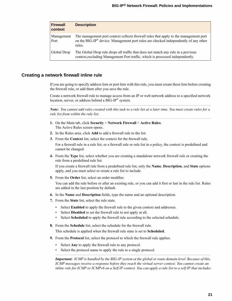
The management port context collects firewall rules that apply to the management porton the BIG-IP® device. Management port rules are checked independently of any otherrules.
ManagementPort
The Global Drop rule drops all traffic that does not match any rule in a previouscontext,excluding Management Port traffic, which is processed independently.
Global Drop
Creating a network firewall inline rule
If you are going to specify address lists or port lists with this rule, you must create these lists before creatingthe firewall rule, or add them after you save the rule.
Create a network firewall rule to manage access from an IP or web network address to a specified networklocation, server, or address behind a BIG-IP® system.
Note: You cannot add rules created with this task to a rule list at a later time. You must create rules for arule list from within the rule list.
1. On the Main tab, click Security > Network Firewall > Active Rules.The Active Rules screen opens.
2. In the Rules area, click Add to add a firewall rule to the list.3. From the Context list, select the context for the firewall rule.
For a firewall rule in a rule list, or a firewall rule or rule list in a policy, the context is predefined andcannot be changed.
4. From the Type list, select whether you are creating a standalone network firewall rule or creating therule from a predefined rule list.If you create a firewall rule from a predefined rule list, only the Name, Description, and State optionsapply, and you must select or create a rule list to include.
5. From the Order list, select an order modifier.You can add the rule before or after an existing rule, or you can add it first or last in the rule list. Rulesare added in the last position by default.
6. In the Name and Description fields, type the name and an optional description.7. From the State list, select the rule state.
• Select Enabled to apply the firewall rule to the given context and addresses.• Select Disabled to set the firewall rule to not apply at all.• Select Scheduled to apply the firewall rule according to the selected schedule.
8. From the Schedule list, select the schedule for the firewall rule.This schedule is applied when the firewall rule state is set to Scheduled.
9. From the Protocol list, select the protocol to which the firewall rule applies.
• Select Any to apply the firewall rule to any protocol.• Select the protocol name to apply the rule to a single protocol.
Important: ICMP is handled by the BIG-IP system at the global or route domain level. Because of this,ICMP messages receive a response before they reach the virtual server context. You cannot create aninline rule for ICMP or ICMPv6 on a Self IP context. You can apply a rule list to a self IP that includes
21
BIG-IP® Network Firewall: Policies and Implementations

a rule for ICMP or ICMPv6; however, such a rule will be ignored. To apply firewall actions to the ICMPprotocol, create a rule with the global or route domain context. ICMP rules are evaluated only forICMP forwarding requests, and not for the IP addresses of the BIG-IP system itself.
Note: Note that you must select a protocol if you specify ports.
10. From the Source Address/Region list, select the type of source address to which this rule applies.
• Select Any to have the rule apply to any packet source IP address.• Select Specify and click Address to specify one or more packet source IP addresses to which the
rule applies. When selected, you can type single IP addresses into the Address field, then clickAddto add them to the address list.
• Select Specify and clickAddress List to select a predefined list of packet source addresses to whichthe rule applies. To use an address list with this rule, select the address list and click the Add button.Similarly, to remove the list from this rule, select the list and click the Delete button.
• Select Specify and clickAddress Range to specify a contiguous range of packet source IP addressesto which the rule applies. When selected, you can type a start and end IP address in the fields, thenclick Add to add the IP address range to the address list.
• Select Specify and click Country/Region to identify the geographic origin of packet sources, andto apply rules based on selected geographic locations. When selected, a field appears in which youcan select a country. For many countries, an extra field appears after you select the country, in whichyou can select a state or province. If you do not select a specific state or province, the entire countryis selected. After you select a geographic location, click Add to add it to the Source address list.
11. From the Source Port list, select the type of packet source ports to which this rule applies.
• Select Any to have the rule apply to any packet source port.• Select Specify and click Port to specify one or more packet source ports to which the rule applies.
When selected, you can type single port numbers into the Port field, then click Add to add them tothe port list.
• Select Specify and click Port Range to specify a list of contiguous packet source port numbers towhich the rule applies. When selected, you can type the start and end ports into the fields, then clickAdd to add the ports to the port list.
• Select Specify and click Port List to select a predefined list of packet source ports to which the ruleapplies. To use a port list with this rule, select the port list and click the Add button. Similarly, toremove the list from this rule, select the list and click the Delete button.
12. From the Source VLAN/Tunnel list, select the VLAN on which this rule applies.
• Select Any to have the rule apply to traffic on any VLAN through which traffic enters the firewall.• Select Specify to specify one or more VLANs on the firewall to which the rule applies. To use a
VLAN with this rule, move the VLAN from the Available list to the Selected list by clicking the<< button. Similarly, to remove the VLAN from this rule, click the >> button to move the VLANfrom the Selected list to the Available list.
13. From the Destination Address/Region list, select the type of packet destination address to which thisrule applies.
• Select Any to have the rule apply to any IP packet destination address.• Select Specify and click Address to specify one or more packet destination IP addresses to which
the rule applies. When selected, you can type single IP addresses into the Address field, then clickAdd to add them to the address list.
• Select Specify and click Address List to select a predefined list of packet destination addresses towhich the rule applies. To use an address list with this rule, select the address list and click the Addbutton. Similarly, to remove the list from this rule, select the list and click the Delete button.
22
About Firewall Rules and Rule Lists

• Select Specify and click Address Range to specify a contiguous range of packet destination IPaddresses to which the rule applies. When selected, you can type a start and end IP address in thefields, then click Add to add the IP address range to the address list.
• Select Specify and clickCountry/Region to identify the geographic packet destination, and to applyrules based on specific geographic locations. When selected, a field appears in which you can selecta country. For many countries, an extra field appears after you select the country, in which you canselect a state or province. If you do not select a specific state or province, the entire country is selected.After you select a geographic location, click Add to add it to the Destination address list.
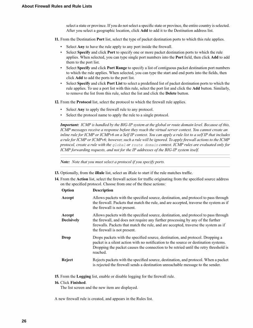
14. From the Destination Port list, select the type of packet destination ports to which this rule applies.
• Select Any to have the rule apply to any port inside the firewall.• Select Specify and click Port to specify one or more packet destination ports to which the rule
applies. When selected, you can type single port numbers into the Port field, then click Add to addthem to the port list.
• Select Specify and click Port Range to specify a list of contiguous packet destination port numbersto which the rule applies. When selected, you can type the start and end ports into the fields, thenclick Add to add the ports to the port list.
• Select Specify and click Port List to select a predefined list of packet destination ports to which therule applies. To use a port list with this rule, select the port list and click the Add button. Similarly,to remove the list from this rule, select the list and click the Delete button.
15. Optionally, from the iRule list, select an iRule to start if the rule matches traffic.16. From the Action list, select the firewall action for traffic originating from the specified source address
on the specified protocol. Choose from one of the these actions:DescriptionOption
Allows packets with the specified source, destination, and protocol to pass throughthe firewall. Packets that match the rule, and are accepted, traverse the system as ifthe firewall is not present.
Accept
Allows packets with the specified source, destination, and protocol to pass throughthe firewall, and does not require any further processing by any of the further
AcceptDecisively
firewalls. Packets that match the rule, and are accepted, traverse the system as ifthe firewall is not present.
Drops packets with the specified source, destination, and protocol. Dropping apacket is a silent action with no notification to the source or destination systems.
Drop
Dropping the packet causes the connection to be retried until the retry threshold isreached.
Rejects packets with the specified source, destination, and protocol. When a packetis rejected the firewall sends a destination unreachable message to the sender.
Reject
17. From the Logging list, enable or disable logging for the firewall rule.18. Click Finished.
The list screen and the new item are displayed.
The new firewall rule is created.
About firewall rule lists
The BIG-IP® Network Firewall uses rule lists to collect multiple rules. Rule lists function differentlydepending on how you create them with Advanced Firewall Manager™ (AFM™).
23
BIG-IP® Network Firewall: Policies and Implementations

If you create a rule list with Security > Network Firewall > Rule Lists > Create:This type of rule list is defined with a name and optional description. Once you create a rule list of thistype, you can create and add one or more individual firewall rules to it. You can only add firewall rulesby creating them from within the rule list. This type of rule list cannot be used on its own, but must beselected in an Active Rules list, or in a Policy Rules list.
If you create a rule list with Security > Network Firewall > Active Rules > Add and selectthe Type as Rule List:
This type of rule list is defined with a name and optional description. You can specify a context (Global,Route Domain, Virtual Server, or Self IP). However, you cannot add individual rules to this rule list.Instead, you select a single rule list you have already created, or one of the predefined rule lists. Thistype of rule list is used to activate a rule list in the configuration.
If you create a rule list with Security > Network Firewall > Policies > policy_name > Addand select the Type as Rule List:
This type of rule list is defined with a name and optional description. You cannot specify a context asthe context is determined by the policy. You cannot add individual rules to this rule list. Instead, youselect a single rule list you have already created, or one of the predefined rule lists. This type of rule listis used to activate a rule list in a policy.
Creating a network firewall rule list
Create a network firewall rule list, to which you can add firewall rules.
1. On the Main tab, click Security > Network Firewall > Rule Lists.The Rule Lists screen opens.
2. Click the Create button to create a new rule list.3. In the Name and Description fields, type the name and an optional description.4. Click Finished.
The list screen and the new item are displayed.
The firewall rule list appears in the list.
Add firewall rules to the rule list to define source, destination, and firewall actions.
Adding a network firewall rule to a rule list
Before you add a firewall rule to a rule list, you must create a rule list.
Use this procedure to add a firewall rule to a rule list.
1. On the Main tab, click Security > Network Firewall > Rule Lists.The Rule Lists screen opens.
2. In the list, click the name of a rule list you previously created.The Rule List properties screen opens.
3. In the Rules area, click Add to add a firewall rule to the list.4. In the Name and Description fields, type the name and an optional description.5. From the State list, select the rule state.
• Select Enabled to apply the firewall rule to the given context and addresses.• Select Disabled to set the firewall rule to not apply at all.• Select Scheduled to apply the firewall rule according to the selected schedule.
6. From the Schedule list, select the schedule for the firewall rule.
24
About Firewall Rules and Rule Lists

This schedule is applied when the firewall rule state is set to Scheduled.
7. From the Source Address/Region list, select the type of source address to which this rule applies.
• Select Any to have the rule apply to any packet source IP address.• Select Specify and click Address to specify one or more packet source IP addresses to which the
rule applies. When selected, you can type single IP addresses into the Address field, then clickAddto add them to the address list.
• Select Specify and clickAddress List to select a predefined list of packet source addresses to whichthe rule applies. To use an address list with this rule, select the address list and click the Add button.Similarly, to remove the list from this rule, select the list and click the Delete button.
• Select Specify and clickAddress Range to specify a contiguous range of packet source IP addressesto which the rule applies. When selected, you can type a start and end IP address in the fields, thenclick Add to add the IP address range to the address list.
• Select Specify and click Country/Region to identify the geographic origin of packet sources, andto apply rules based on selected geographic locations. When selected, a field appears in which youcan select a country. For many countries, an extra field appears after you select the country, in whichyou can select a state or province. If you do not select a specific state or province, the entire countryis selected. After you select a geographic location, click Add to add it to the Source address list.
8. From the Source Port list, select the type of packet source ports to which this rule applies.
• Select Any to have the rule apply to any packet source port.• Select Specify and click Port to specify one or more packet source ports to which the rule applies.
When selected, you can type single port numbers into the Port field, then click Add to add them tothe port list.
• Select Specify and click Port Range to specify a list of contiguous packet source port numbers towhich the rule applies. When selected, you can type the start and end ports into the fields, then clickAdd to add the ports to the port list.
• Select Specify and click Port List to select a predefined list of packet source ports to which the ruleapplies. To use a port list with this rule, select the port list and click the Add button. Similarly, toremove the list from this rule, select the list and click the Delete button.
9. From the Source VLAN/Tunnel list, select the VLAN on which this rule applies.
• Select Any to have the rule apply to traffic on any VLAN through which traffic enters the firewall.• Select Specify to specify one or more VLANs on the firewall to which the rule applies. To use a
VLAN with this rule, move the VLAN from the Available list to the Selected list by clicking the<< button. Similarly, to remove the VLAN from this rule, click the >> button to move the VLANfrom the Selected list to the Available list.
10. From the Destination Address/Region list, select the type of packet destination address to which thisrule applies.
• Select Any to have the rule apply to any IP packet destination address.• Select Specify and click Address to specify one or more packet destination IP addresses to which
the rule applies. When selected, you can type single IP addresses into the Address field, then clickAdd to add them to the address list.
• Select Specify and click Address List to select a predefined list of packet destination addresses towhich the rule applies. To use an address list with this rule, select the address list and click the Addbutton. Similarly, to remove the list from this rule, select the list and click the Delete button.
• Select Specify and click Address Range to specify a contiguous range of packet destination IPaddresses to which the rule applies. When selected, you can type a start and end IP address in thefields, then click Add to add the IP address range to the address list.
• Select Specify and clickCountry/Region to identify the geographic packet destination, and to applyrules based on specific geographic locations. When selected, a field appears in which you can selecta country. For many countries, an extra field appears after you select the country, in which you can
25
BIG-IP® Network Firewall: Policies and Implementations
select a state or province. If you do not select a specific state or province, the entire country is selected.After you select a geographic location, click Add to add it to the Destination address list.
11. From the Destination Port list, select the type of packet destination ports to which this rule applies.
• Select Any to have the rule apply to any port inside the firewall.• Select Specify and click Port to specify one or more packet destination ports to which the rule
applies. When selected, you can type single port numbers into the Port field, then click Add to addthem to the port list.
• Select Specify and click Port Range to specify a list of contiguous packet destination port numbersto which the rule applies. When selected, you can type the start and end ports into the fields, thenclick Add to add the ports to the port list.
• Select Specify and click Port List to select a predefined list of packet destination ports to which therule applies. To use a port list with this rule, select the port list and click the Add button. Similarly,to remove the list from this rule, select the list and click the Delete button.
12. From the Protocol list, select the protocol to which the firewall rule applies.
• Select Any to apply the firewall rule to any protocol.• Select the protocol name to apply the rule to a single protocol.
Important: ICMP is handled by the BIG-IP system at the global or route domain level. Because of this,ICMP messages receive a response before they reach the virtual server context. You cannot create aninline rule for ICMP or ICMPv6 on a Self IP context. You can apply a rule list to a self IP that includesa rule for ICMP or ICMPv6; however, such a rule will be ignored. To apply firewall actions to the ICMPprotocol, create a rule with the global or route domain context. ICMP rules are evaluated only forICMP forwarding requests, and not for the IP addresses of the BIG-IP system itself.
Note: Note that you must select a protocol if you specify ports.
13. Optionally, from the iRule list, select an iRule to start if the rule matches traffic.14. From the Action list, select the firewall action for traffic originating from the specified source address
on the specified protocol. Choose from one of the these actions:DescriptionOption
Allows packets with the specified source, destination, and protocol to pass throughthe firewall. Packets that match the rule, and are accepted, traverse the system as ifthe firewall is not present.
Accept
Allows packets with the specified source, destination, and protocol to pass throughthe firewall, and does not require any further processing by any of the further
AcceptDecisively
firewalls. Packets that match the rule, and are accepted, traverse the system as ifthe firewall is not present.
Drops packets with the specified source, destination, and protocol. Dropping apacket is a silent action with no notification to the source or destination systems.
Drop
Dropping the packet causes the connection to be retried until the retry threshold isreached.
Rejects packets with the specified source, destination, and protocol. When a packetis rejected the firewall sends a destination unreachable message to the sender.
Reject
15. From the Logging list, enable or disable logging for the firewall rule.16. Click Finished.
The list screen and the new item are displayed.
A new firewall rule is created, and appears in the Rules list.
26
About Firewall Rules and Rule Lists

Activating a rule list in active rules or in a policy
The rule list created from the active rules page, or from a policy, is a container in which you can select andactivate one of the rule lists that you created with Security > Network Firewall > Rule Lists > Create, orone of the predefined system rule lists.
1. From the Context list, select the context for the firewall rule.For a firewall rule in a rule list, or a firewall rule or rule list in a policy, the context is predefined andcannot be changed.
2. In the Name and Description fields, type the name and an optional description.3. From the Rule List list, select a rule list to activate in the policy or configuration.4. From the State list, select the rule state.
• Select Enabled to apply the firewall rule to the given context and addresses.• Select Disabled to set the firewall rule to not apply at all.• Select Scheduled to apply the firewall rule according to the selected schedule.
5. Click Finished.The list screen and the new item are displayed.
The firewall rule list you selected is activated in the Active Rules list or policy.
27
BIG-IP® Network Firewall: Policies and Implementations

Chapter
3About Firewall Rule Addresses and Ports
• About firewall rule addresses and ports• About address lists• About port lists
About firewall rule addresses and ports
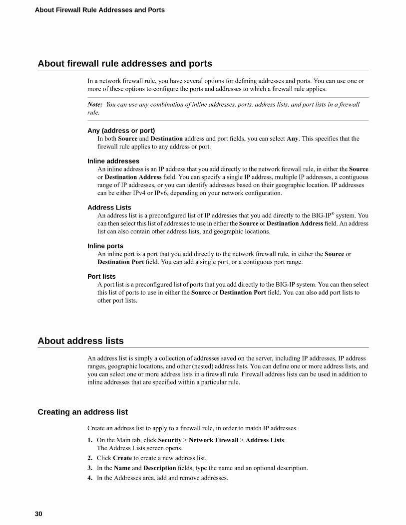
In a network firewall rule, you have several options for defining addresses and ports. You can use one ormore of these options to configure the ports and addresses to which a firewall rule applies.
Note: You can use any combination of inline addresses, ports, address lists, and port lists in a firewallrule.
Any (address or port)In both Source and Destination address and port fields, you can select Any. This specifies that thefirewall rule applies to any address or port.
Inline addressesAn inline address is an IP address that you add directly to the network firewall rule, in either the Sourceor Destination Address field. You can specify a single IP address, multiple IP addresses, a contiguousrange of IP addresses, or you can identify addresses based on their geographic location. IP addressescan be either IPv4 or IPv6, depending on your network configuration.
Address ListsAn address list is a preconfigured list of IP addresses that you add directly to the BIG-IP® system. Youcan then select this list of addresses to use in either the Source orDestination Address field. An addresslist can also contain other address lists, and geographic locations.
Inline portsAn inline port is a port that you add directly to the network firewall rule, in either the Source orDestination Port field. You can add a single port, or a contiguous port range.
Port listsA port list is a preconfigured list of ports that you add directly to the BIG-IP system. You can then selectthis list of ports to use in either the Source or Destination Port field. You can also add port lists toother port lists.
About address lists
An address list is simply a collection of addresses saved on the server, including IP addresses, IP addressranges, geographic locations, and other (nested) address lists. You can define one or more address lists, andyou can select one or more address lists in a firewall rule. Firewall address lists can be used in addition toinline addresses that are specified within a particular rule.
Creating an address list
Create an address list to apply to a firewall rule, in order to match IP addresses.
1. On the Main tab, click Security > Network Firewall > Address Lists.The Address Lists screen opens.
2. Click Create to create a new address list.3. In the Name and Description fields, type the name and an optional description.4. In the Addresses area, add and remove addresses.
30
About Firewall Rule Addresses and Ports
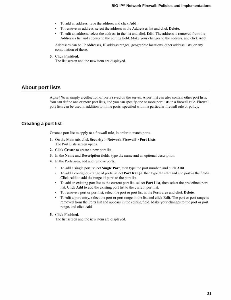
• To add an address, type the address and click Add.• To remove an address, select the address in the Addresses list and click Delete.• To edit an address, select the address in the list and click Edit. The address is removed from the
Addresses list and appears in the editing field. Make your changes to the address, and click Add.
Addresses can be IP addresses, IP address ranges, geographic locations, other address lists, or anycombination of these.
5. Click Finished.The list screen and the new item are displayed.
About port lists
A port list is simply a collection of ports saved on the server. A port list can also contain other port lists.You can define one or more port lists, and you can specify one or more port lists in a firewall rule. Firewallport lists can be used in addition to inline ports, specified within a particular firewall rule or policy.
Creating a port list
Create a port list to apply to a firewall rule, in order to match ports.
1. On the Main tab, click Security > Network Firewall > Port Lists.The Port Lists screen opens.
2. Click Create to create a new port list.3. In the Name and Description fields, type the name and an optional description.4. In the Ports area, add and remove ports.
• To add a single port, select Single Port, then type the port number, and click Add.• To add a contiguous range of ports, select Port Range, then type the start and end port in the fields.
Click Add to add the range of ports to the port list.• To add an existing port list to the current port list, select Port List, then select the predefined port
list. Click Add to add the existing port list to the current port list.• To remove a port or port list, select the port or port list in the Ports area and click Delete.• To edit a port entry, select the port or port range in the list and click Edit. The port or port range is
removed from the Ports list and appears in the editing field. Make your changes to the port or portrange, and click Add.
5. Click Finished.The list screen and the new item are displayed.
31
BIG-IP® Network Firewall: Policies and Implementations


Chapter
4About Network Firewall Schedules
• About Network Firewall schedules
About Network Firewall schedules
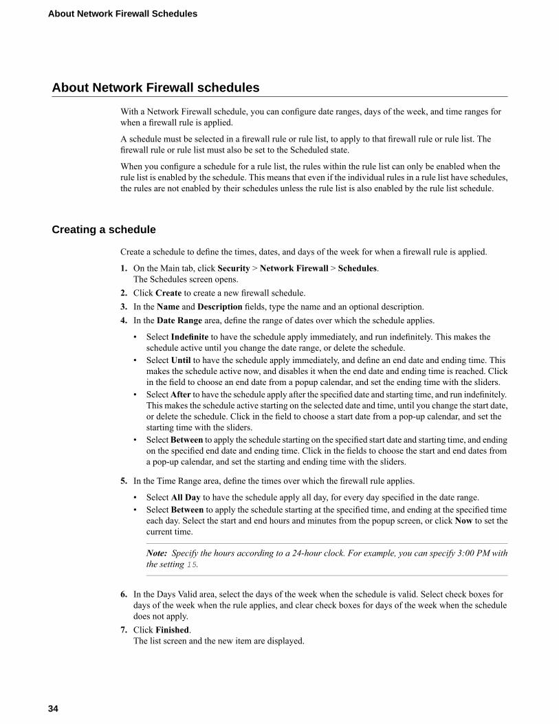
With a Network Firewall schedule, you can configure date ranges, days of the week, and time ranges forwhen a firewall rule is applied.
A schedule must be selected in a firewall rule or rule list, to apply to that firewall rule or rule list. Thefirewall rule or rule list must also be set to the Scheduled state.
When you configure a schedule for a rule list, the rules within the rule list can only be enabled when therule list is enabled by the schedule. This means that even if the individual rules in a rule list have schedules,the rules are not enabled by their schedules unless the rule list is also enabled by the rule list schedule.
Creating a schedule
Create a schedule to define the times, dates, and days of the week for when a firewall rule is applied.
1. On the Main tab, click Security > Network Firewall > Schedules.The Schedules screen opens.
2. Click Create to create a new firewall schedule.3. In the Name and Description fields, type the name and an optional description.4. In the Date Range area, define the range of dates over which the schedule applies.
• Select Indefinite to have the schedule apply immediately, and run indefinitely. This makes theschedule active until you change the date range, or delete the schedule.
• Select Until to have the schedule apply immediately, and define an end date and ending time. Thismakes the schedule active now, and disables it when the end date and ending time is reached. Clickin the field to choose an end date from a popup calendar, and set the ending time with the sliders.
• SelectAfter to have the schedule apply after the specified date and starting time, and run indefinitely.This makes the schedule active starting on the selected date and time, until you change the start date,or delete the schedule. Click in the field to choose a start date from a pop-up calendar, and set thestarting time with the sliders.
• SelectBetween to apply the schedule starting on the specified start date and starting time, and endingon the specified end date and ending time. Click in the fields to choose the start and end dates froma pop-up calendar, and set the starting and ending time with the sliders.
5. In the Time Range area, define the times over which the firewall rule applies.
• Select All Day to have the schedule apply all day, for every day specified in the date range.• Select Between to apply the schedule starting at the specified time, and ending at the specified time
each day. Select the start and end hours and minutes from the popup screen, or click Now to set thecurrent time.
Note: Specify the hours according to a 24-hour clock. For example, you can specify 3:00 PM withthe setting 15.
6. In the Days Valid area, select the days of the week when the schedule is valid. Select check boxes fordays of the week when the rule applies, and clear check boxes for days of the week when the scheduledoes not apply.
7. Click Finished.The list screen and the new item are displayed.
34
About Network Firewall Schedules

Chapter
5About IP Address Intelligence in the Network Firewall
• About IP intelligence policies in the networkfirewall
• About IP intelligence blacklist classes• About IP intelligence feed lists• Configuring a policy to check addresses
against IP intelligence

About IP intelligence policies in the network firewall
In the network firewall, you can configure policies to check traffic against an IP intelligence database. Suchtraffic can be handled automatically if it originates from known-bad or questionable IP addresses. In addition,you can configure policies to automatically query feed lists that specify blacklist and whitelist IP addressentries, and configure actions for those entries. You can control the actions for each IP intelligence categoryby specifying such actions in a policy. Furthermore, you can configure policies to apply default actions tofeed lists, and apply such policies at the global context, to a virtual server, or on a route domain.
Figure 2: IP Intelligence Policy container, and included elements
Enabling IP address intelligence
The requirements for using IP address intelligence are:
• The system must have an IP Intelligence license.• The system must have an Internet connection either directly or through an HTTP proxy server.• The system must have DNS configured (go to System > Configuration > Device > DNS).
Important: IP address intelligence is enabled by default. You only need to enable it if it was previouslydisabled.
36
About IP Address Intelligence in the Network Firewall

To enable IP address intelligence on the BIG-IP® system, you enable auto-update to connect the system tothe IP intelligence database.
1. Log in to the command line for the BIG-IP® system.2. To determine whether IP intelligence is enabled, type the following command: tmsh list sys db
iprep.autoupdateIf the value of the iprep.autoupdate variable is disable, IP intelligence is not enabled. If it isenable, your task is complete.
3. At the prompt, type tmsh modify sys db iprep.autoupdate value enableThe system downloads the IP intelligence database and stores it in the binary file,/var/IpRep/F5IpRep.dat. It is updated every 5 minutes.
4. If the BIG-IP system is behind a firewall, make sure that the BIG-IP system has external access tovector.brightcloud.com using port 443.That is the IP Intelligence server from which the system gets IP Intelligence information.
5. (Optional) If the BIG-IP system connects to the Internet using a forward proxy server, set these systemdatabase variables.a) Type tmsh modify sys db proxy.host value hostname to specify the host name of the
proxy server.b) Type tmsh modify sys db proxy.port value port_number to specify the port number of
the proxy server.c) Type tmsh modify sys db proxy.username value username to specify the user name to
log in to the proxy server.d) Type tmsh modify sys db proxy.password value password to specify the password to
log in to the proxy server.
The IP address intelligence feature remains enabled unless you disable it with the command tmsh modifysys db iprep.autoupdate value disable.
You can configure IP intelligence for Advanced Firewall Manager by assigning IP intelligence policies tothe global, route domain, or virtual server context.
IP address intelligence categories
Along with the IP address, the IP intelligence database stores the category that explains the reason that theIP address is considered untrustworthy.
DescriptionCategory Name
IP addresses of computers that are infectedwithmalicious software (Botnet Commandand Control channels, and infected zombie machines) and are controlled as a group
Botnets
by a Bot master, and are now part of a botnet. Hackers can exploit botnets to sendspam messages, launch various attacks, or cause target systems to behave in otherunpredictable ways.
IP addresses and networks that are used by cloud providers.Cloud ProviderNetworks
IP addresses that have launched denial-of-service (DoS) attacks, distributeddenial-of-service (DDoS) attacks, anomalous SYN flood attacks, or anomalous traffic
Denial-of-Service
detection. These attacks are usually requests for legitimate services, but occur at sucha fast rate that targeted systems cannot respond quickly enough and become boggeddown or unable to service legitimate clients.
37
BIG-IP® Network Firewall: Policies and Implementations

DescriptionCategory Name
IP addresses that contain criminally obscene or potentially criminal internet copyrightand intellectual property violations.
Illegal Web sites
Active IP addresses that issue HTTP requests with a low reputation index score, orthat are known malicious web sites offering or distributing malware, shell code,rootkits, worms, or viruses.
Infected Sources
IP addresses that host phishing sites, and other kinds of fraud activities, such as adclick fraud or gaming fraud.
Phishing
IP addresses that are associated with web proxies that shield the originator's IP address(such as proxy and anonymization services). This category also includes TORanonymizer addresses.
Proxy/AnonymousProxies
IP addresses that are involved in reconnaissance, such as probes, host scan, domainscan, and password brute force, typically to identify vulnerabilities for later exploits.
Scanners
IP addresses that are known to distribute large amounts of spam email by tunnelingspammessages through proxy, anomalous SMTP activities, and forum spam activities.
Spam Sources
IP addresses involved in cross site scripting, iFrame injection, SQL injection, crossdomain injection, or domain password brute force.
Web Attacks
Active IP addresses that have exercised various exploits against Windows resourcesby offering or distributing malware, shell code, rootkits, worms, or viruses usingbrowsers, programs, downloaded files, scripts, or operating system vulnerabilities.
Windows Exploits
About IP intelligence blacklist classes
Blacklist classes are categories you can use to differentiate between types of blacklisted URLs. You canspecify up to 62 blacklist classes, including 11 that are predefined on the system. A blacklist class definitionconsists only of a name and description. You can specify actions and logging options for each blacklistclass you create, and for predefined classes, in an IP intelligence policy. The 11 predefined blacklist classesare automatically available for selection in an IP intelligence policy.
Creating a blacklist class
You can create a blacklist class to configure policy-based responses to specific types of addresses. Thenyou can specify an address as belonging to a blacklist class so you can see the types of classes that aretriggered in the logs, and so you can provide unique responses on a per-class basis.
1. On the Main tab, click Security > Network Firewall > IP Intelligence > Blacklist Classes.The Blacklist Classes screen opens.
2. Click Create to create a new IP Intelligence blacklist class.3. In the Name field, type a name for the blacklist class.4. In the Description field, type a description for the blacklist class.5. Click Finished.
The list screen and the new item are displayed.
38
About IP Address Intelligence in the Network Firewall
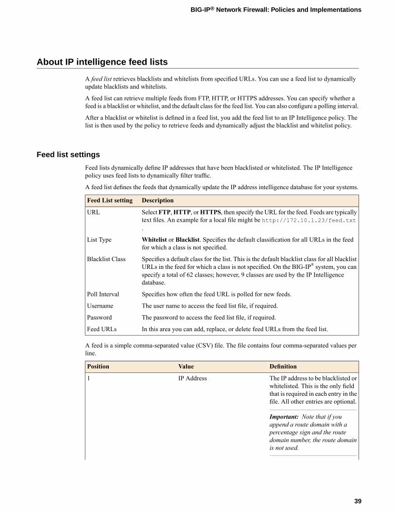
About IP intelligence feed lists
A feed list retrieves blacklists and whitelists from specified URLs. You can use a feed list to dynamicallyupdate blacklists and whitelists.
A feed list can retrieve multiple feeds from FTP, HTTP, or HTTPS addresses. You can specify whether afeed is a blacklist or whitelist, and the default class for the feed list. You can also configure a polling interval.
After a blacklist or whitelist is defined in a feed list, you add the feed list to an IP Intelligence policy. Thelist is then used by the policy to retrieve feeds and dynamically adjust the blacklist and whitelist policy.
Feed list settings
Feed lists dynamically define IP addresses that have been blacklisted or whitelisted. The IP Intelligencepolicy uses feed lists to dynamically filter traffic.
A feed list defines the feeds that dynamically update the IP address intelligence database for your systems.
DescriptionFeed List setting
SelectFTP,HTTP, orHTTPS, then specify the URL for the feed. Feeds are typicallytext files. An example for a local file might be http://172.10.1.23/feed.txt.
URL
Whitelist or Blacklist. Specifies the default classification for all URLs in the feedfor which a class is not specified.
List Type
Specifies a default class for the list. This is the default blacklist class for all blacklistURLs in the feed for which a class is not specified. On the BIG-IP® system, you can
Blacklist Class
specify a total of 62 classes; however, 9 classes are used by the IP Intelligencedatabase.
Specifies how often the feed URL is polled for new feeds.Poll Interval
The user name to access the feed list file, if required.Username
The password to access the feed list file, if required.Password
In this area you can add, replace, or delete feed URLs from the feed list.Feed URLs
A feed is a simple comma-separated value (CSV) file. The file contains four comma-separated values perline.
DefinitionValuePosition
The IP address to be blacklisted orwhitelisted. This is the only field
IP Address1
that is required in each entry in thefile. All other entries are optional.
Important: Note that if youappend a route domain with apercentage sign and the routedomain number, the route domainis not used.
39
BIG-IP® Network Firewall: Policies and Implementations
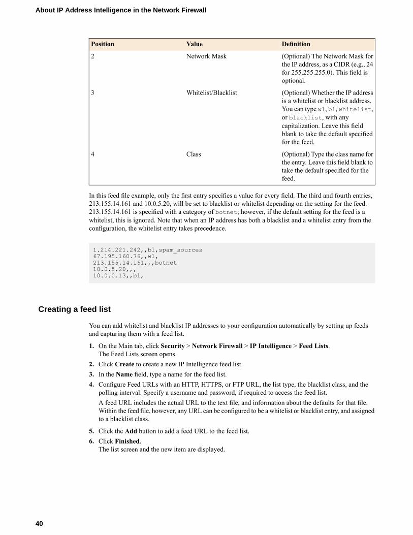
DefinitionValuePosition
(Optional) The Network Mask forthe IP address, as a CIDR (e.g., 24
Network Mask2
for 255.255.255.0). This field isoptional.
(Optional) Whether the IP addressis a whitelist or blacklist address.
Whitelist/Blacklist3
You can type wl, bl, whitelist,or blacklist, with anycapitalization. Leave this fieldblank to take the default specifiedfor the feed.
(Optional) Type the class name forthe entry. Leave this field blank to
Class4
take the default specified for thefeed.
In this feed file example, only the first entry specifies a value for every field. The third and fourth entries,213.155.14.161 and 10.0.5.20, will be set to blacklist or whitelist depending on the setting for the feed.213.155.14.161 is specified with a category of botnet; however, if the default setting for the feed is awhitelist, this is ignored. Note that when an IP address has both a blacklist and a whitelist entry from theconfiguration, the whitelist entry takes precedence.
1.214.221.242,,bl,spam_sources67.195.160.76,,wl,213.155.14.161,,,botnet10.0.5.20,,,10.0.0.13,,bl,
Creating a feed list
You can add whitelist and blacklist IP addresses to your configuration automatically by setting up feedsand capturing them with a feed list.
1. On the Main tab, click Security > Network Firewall > IP Intelligence > Feed Lists.The Feed Lists screen opens.
2. Click Create to create a new IP Intelligence feed list.3. In the Name field, type a name for the feed list.4. Configure Feed URLs with an HTTP, HTTPS, or FTP URL, the list type, the blacklist class, and the
polling interval. Specify a username and password, if required to access the feed list.A feed URL includes the actual URL to the text file, and information about the defaults for that file.Within the feed file, however, any URL can be configured to be a whitelist or blacklist entry, and assignedto a blacklist class.
5. Click the Add button to add a feed URL to the feed list.6. Click Finished.
The list screen and the new item are displayed.
40
About IP Address Intelligence in the Network Firewall

Configuring a policy to check addresses against IP intelligence
You can verify IP addresses against the preconfigured IP Intelligence database, and against IPs from yourown feed lists, by creating an IP Intelligence policy.
1. On the Main tab, click Security > Network Firewall > IP Intelligence > Policies.The IP Intelligence Policies screen opens.
2. Click Create to create a new IP Intelligence policy.3. In the Name field, type a name for the IP intelligence policy.4. To add feed lists to the policy, click on the name of an available feed list, and click the << button to add
it to the Selected list.5. Set the default action for the policy to Accept or Reject.
• Select Accept to allow packets from uncategorized addresses on the feed list.• Select Reject to drop and send a reject message for packets from uncategorized addresses on the
feed list.
The default action applies to addresses that are not assigned a blacklist class in the feed list. The IPIntelligence feature uses the action specified in a feed list entry, when available.
6. Set the default log action.
• Disabled does not log matches.• Log Black List Class Matches logs IP addresses that match blacklist classes.• Log White List Overrides logs only whitelist matches that override blacklist matches.• Log Black List Class Matches and White List Overrides logs all black list matches, and all
whitelist matches that override blacklist matches.
Note: Whitelist matches always override blacklist matches.
7. To configure matching actions and logging for custom blacklist classes, add Blacklist Classes in theBlacklist Matching Policy area. Select a class from the list of predefined and user-defined blacklistclasses, and set the default action and default logging action for the class, then click Add to add theblacklist class to the policy.
Note: The default action for a blacklist class is always Reject.
8. For each class, you can select a default action.
• Select Accept to allow packets from sources of the specified type, as identified by the IP addressintelligence database.
• Select Reject to drop and send a reject message for packets from sources of the specified type, asidentified by the IP address intelligence database.
9. Set the default log action for the blacklist class.
• Disabled does not log matches.• Log Matches logs IP addresses that match blacklist classes.• Log Overrides logs only whitelist matches that override blacklist matches.• Log Matches and Overrides logs all black list matches, and all whitelist matches that override
blacklist matches.
Note: Whitelist matches always override blacklist matches.
41
BIG-IP® Network Firewall: Policies and Implementations

10. Click Finished.The list screen and the new item are displayed.
Assigning a global IP Intelligence policy
You can assign an IP Intelligence policy globally, to apply blacklist and whitelist matching actions andlogging to all traffic.
1. On the Main tab, click Security > Network Firewall > IP Intelligence > Policies.The IP Intelligence Policies screen opens.
2. From theGlobal Policy list, select the IP Intelligence policy to apply to all traffic on the BIG-IP system.3. Click Update.
The list screen and the updated item are displayed.
The specified IP Intelligence policy is applied to all traffic.
Assigning an IP Intelligence policy to a virtual server
You can assign an IP Intelligence policy to a virtual server, to apply blacklist and whitelist matching actionsand logging to traffic on that virtual server only.
1. On the Main tab, click Local Traffic > Virtual Servers.The Virtual Server List screen opens.
2. Click the name of the virtual server you want to modify.3. From the Security menu, choose Policies.4. Next to IP Intelligence, select Enabled, then select the IP intelligence policy to apply to traffic on the
virtual server.5. Click Update.
The list screen and the updated item are displayed.
The specified IP Intelligence policy is applied to traffic on the selected virtual server.
Assigning an IP Intelligence policy to a route domain
You can assign an IP Intelligence policy to a route domain, to apply blacklist and whitelist matching actionsand logging to route domain traffic.
1. On the Main tab, click Network > Route Domains.The Route Domain List screen opens.
2. In the Name column, click the name of the relevant route domain.3. From the IP Intelligence Policy list, select an IP Intelligence policy to enforce on this route domain.4. Click Update.
The system displays the list of route domains on the BIG-IP system.
The specified IP Intelligence policy is applied to traffic on the route domain.
42
About IP Address Intelligence in the Network Firewall
Chapter
6About Local Logging with the Network Firewall
• Overview: Configuring local Network Firewallevent logging
• Task summary• Implementation result

Overview: Configuring local Network Firewall event logging
You can configure the BIG-IP® system to log detailed information about BIG-IP system Network Firewallevents and store those logs on the BIG-IP system.
Important: The BIG-IP system Advanced Firewall Manager™ (AFM™) must be licensed and provisionedbefore you can configure Network Firewall event logging.
Task summary
Perform these tasks to configure Network Firewall logging locally on the BIG-IP® system.
Note: Enabling logging and storing the logs locally impacts BIG-IP system performance.
Creating a local Network Firewall Logging profileConfiguring an LTM virtual server for Network Firewall event loggingViewing Network Firewall event logs locally on the BIG-IP systemCreating a Network Firewall rule from a firewall log entryDisabling logging
Creating a local Network Firewall Logging profile
Create a custom Logging profile to log BIG-IP® system Network Firewall events locally on the BIG-IPsystem.
1. On the Main tab, click Security > Event Logs > Logging Profiles.The Logging Profiles list screen opens.
2. Click Create.The New Logging Profile screen opens.
3. In the Profile Name field, type a unique name for the profile.4. Select the Network Firewall check box.5. In the Network Firewall area, from the Publisher list, select local-db-publisher.6. For the Log Rule Matches setting, select how the BIG-IP system logs packets that match ACL rules.
You can select any or all of the options.DescriptionOption
Enables or disables logging of packets that match ACL rulesconfigured with:
Option
action=AcceptAccept
action=DropDrop
action=RejectReject
7. Select the Log IP Errors check box, to enable logging of IP error packets.8. Select the Log TCP Errors check box, to enable logging of TCP error packets.
44
About Local Logging with the Network Firewall
9. Select the Log TCP Events check box, to enable logging of open and close of TCP sessions.10. In the IP Intelligence area, from the Publisher list, select local-db-publisher.
Note: The IP Address Intelligence feature must be enabled and licensed.
11. Enable the Log Translation Fields setting to log both the original IP address and the NAT-translatedIP address for Network Firewall log events.
12. Click Finished.
Assign this custom Network Firewall Logging profile to a virtual server.
Configuring an LTM virtual server for Network Firewall event logging
Ensure that at least one log publisher exists on the BIG-IP® system.
Assign a custom Network Firewall Logging profile to a virtual server when you want the BIG-IP systemto log Network Firewall events on the traffic that the virtual server processes.
Note: This task applies only to LTM®-provisioned systems.
1. On the Main tab, click Local Traffic > Virtual Servers.The Virtual Server List screen opens.
2. Click the name of the virtual server you want to modify.3. On the menu bar, click Security > Policies.
The screen displays Policy settings and Inline Rules settings.4. From the Log Profile list, select Enabled. Then, for the Profile setting, move the profiles that log
specific events to specific locations from the Available list to the Selected list.
Note: If you don't have a custom profile configured, select the predefined logging profile global-networkto log Advanced Firewall Manager™ events. Note that to log global, self IP, and route domain contexts,you must enable a Publisher in the global-network profile.
5. Click Update to save the changes.
Viewing Network Firewall event logs locally on the BIG-IP system
Ensure that the BIG-IP® system is configured to log the types of events you want to view, and to store thelog messages locally on the BIG-IP system.
When the BIG-IP system is configured to log events locally, you can view those events using theConfiguration utility.
1. On the Main tab, click Security > Event Logs > Network > Firewall.The Network Firewall event log displays.
2. To search for specific events, click Custom Search. Drag the event data that you want to search forfrom the Event Log table into the Custom Search table, and then click Search.
45
BIG-IP® Network Firewall: Policies and Implementations

Creating a Network Firewall rule from a firewall log entry
You must be logging network firewall traffic to create a rule from the network firewall logs.
You can create a rule from the local log, from an enforced or staged rule or policy. You might use this tochange the action taken on specific traffic that is matched by a more general rule. You can also use this toreplicate a rule and change some parameter, such as the source or destination ports. Note that the rule youcreate from a log entry already has some information specified, such as source and destination address andports, protocol, and VLAN. You can change any of this information as required.
1. On the Main tab, click Security > Event Logs > Network > Firewall.The Network Firewall event log displays.
2. Select the search parameters to show the desired log results, then click Search.3. Select a log entry, and click Create Rule.4. From the Context list, select the context for the firewall rule.
For a firewall rule in a rule list, or a firewall rule or rule list in a policy, the context is predefined andcannot be changed.
5. In the Name and Description fields, type the name and an optional description.6. From the Type list, select whether you are creating a standalone network firewall rule or creating the
rule from a predefined rule list.If you create a firewall rule from a predefined rule list, only the Name, Description, and State optionsapply, and you must select or create a rule list to include.
7. From the State list, select the rule state.
• Select Enabled to apply the firewall rule to the given context and addresses.• Select Disabled to set the firewall rule to not apply at all.• Select Scheduled to apply the firewall rule according to the selected schedule.
8. From the Schedule list, select the schedule for the firewall rule.This schedule is applied when the firewall rule state is set to Scheduled.
9. From the Protocol list, select the protocol to which the firewall rule applies.
• Select Any to apply the firewall rule to any protocol.• Select the protocol name to apply the rule to a single protocol.
Important: ICMP is handled by the BIG-IP system at the global or route domain level. Because of this,ICMP messages receive a response before they reach the virtual server context. You cannot create aninline rule for ICMP or ICMPv6 on a Self IP context. You can apply a rule list to a self IP that includesa rule for ICMP or ICMPv6; however, such a rule will be ignored. To apply firewall actions to the ICMPprotocol, create a rule with the global or route domain context. ICMP rules are evaluated only forICMP forwarding requests, and not for the IP addresses of the BIG-IP system itself.
Note: Note that you must select a protocol if you specify ports.
10. From the Source Address/Region list, select the type of source address to which this rule applies.
• Select Any to have the rule apply to any packet source IP address.• Select Specify and click Address to specify one or more packet source IP addresses to which the
rule applies. When selected, you can type single IP addresses into the Address field, then clickAddto add them to the address list.
46
About Local Logging with the Network Firewall
• Select Specify and clickAddress List to select a predefined list of packet source addresses to whichthe rule applies. To use an address list with this rule, select the address list and click the Add button.Similarly, to remove the list from this rule, select the list and click the Delete button.
• Select Specify and clickAddress Range to specify a contiguous range of packet source IP addressesto which the rule applies. When selected, you can type a start and end IP address in the fields, thenclick Add to add the IP address range to the address list.
• Select Specify and click Country/Region to identify the geographic origin of packet sources, andto apply rules based on selected geographic locations. When selected, a field appears in which youcan select a country. For many countries, an extra field appears after you select the country, in whichyou can select a state or province. If you do not select a specific state or province, the entire countryis selected. After you select a geographic location, click Add to add it to the Source address list.
11. From the Source Port list, select the type of packet source ports to which this rule applies.
• Select Any to have the rule apply to any packet source port.• Select Specify and click Port to specify one or more packet source ports to which the rule applies.
When selected, you can type single port numbers into the Port field, then click Add to add them tothe port list.
• Select Specify and click Port Range to specify a list of contiguous packet source port numbers towhich the rule applies. When selected, you can type the start and end ports into the fields, then clickAdd to add the ports to the port list.
• Select Specify and click Port List to select a predefined list of packet source ports to which the ruleapplies. To use a port list with this rule, select the port list and click the Add button. Similarly, toremove the list from this rule, select the list and click the Delete button.
12. From the Source VLAN/Tunnel list, select the VLAN on which this rule applies.
• Select Any to have the rule apply to traffic on any VLAN through which traffic enters the firewall.• Select Specify to specify one or more VLANs on the firewall to which the rule applies. To use a
VLAN with this rule, move the VLAN from the Available list to the Selected list by clicking the<< button. Similarly, to remove the VLAN from this rule, click the >> button to move the VLANfrom the Selected list to the Available list.
13. From the Destination Address/Region list, select the type of packet destination address to which thisrule applies.
• Select Any to have the rule apply to any IP packet destination address.• Select Specify and click Address to specify one or more packet destination IP addresses to which
the rule applies. When selected, you can type single IP addresses into the Address field, then clickAdd to add them to the address list.
• Select Specify and click Address List to select a predefined list of packet destination addresses towhich the rule applies. To use an address list with this rule, select the address list and click the Addbutton. Similarly, to remove the list from this rule, select the list and click the Delete button.
• Select Specify and click Address Range to specify a contiguous range of packet destination IPaddresses to which the rule applies. When selected, you can type a start and end IP address in thefields, then click Add to add the IP address range to the address list.
• Select Specify and clickCountry/Region to identify the geographic packet destination, and to applyrules based on specific geographic locations. When selected, a field appears in which you can selecta country. For many countries, an extra field appears after you select the country, in which you canselect a state or province. If you do not select a specific state or province, the entire country is selected.After you select a geographic location, click Add to add it to the Destination address list.
14. From the Destination Port list, select the type of packet destination ports to which this rule applies.
• Select Any to have the rule apply to any port inside the firewall.
47
BIG-IP® Network Firewall: Policies and Implementations
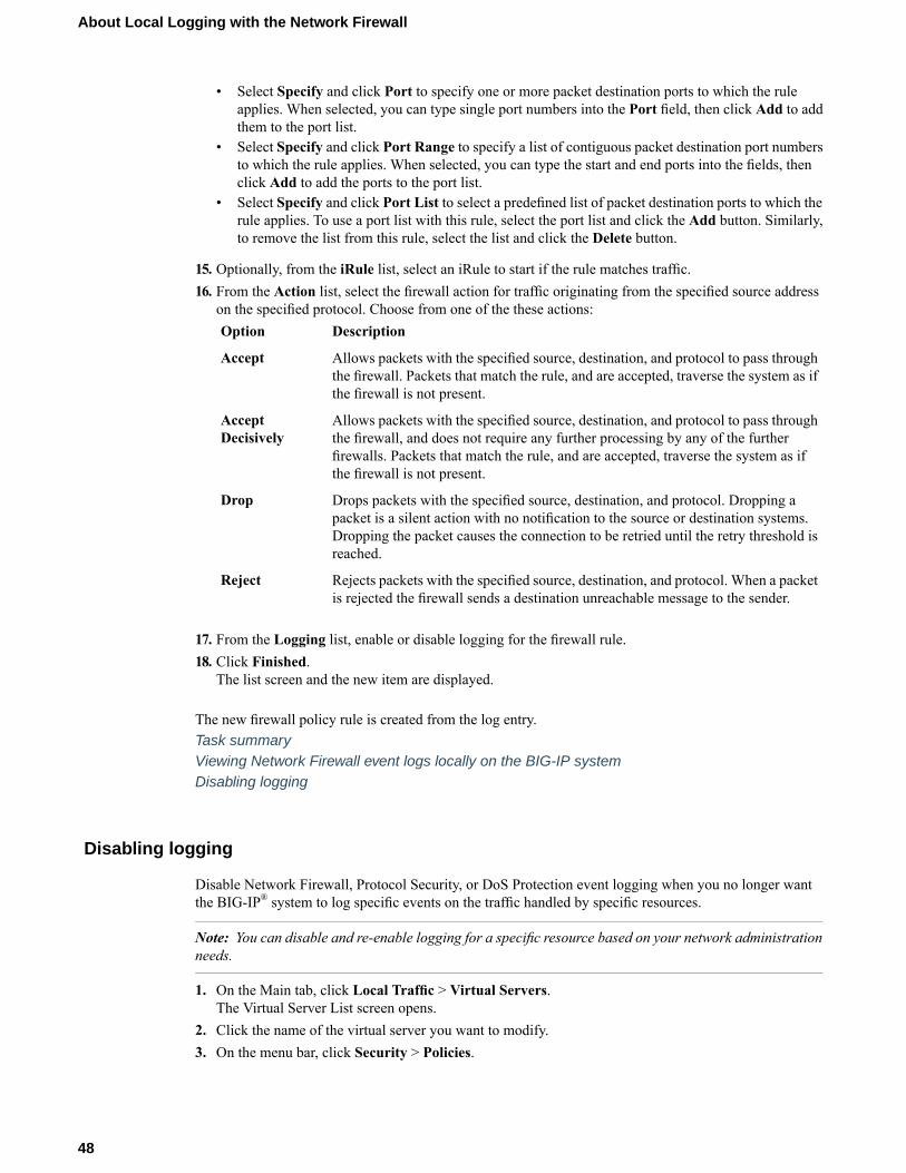
• Select Specify and click Port to specify one or more packet destination ports to which the ruleapplies. When selected, you can type single port numbers into the Port field, then click Add to addthem to the port list.
• Select Specify and click Port Range to specify a list of contiguous packet destination port numbersto which the rule applies. When selected, you can type the start and end ports into the fields, thenclick Add to add the ports to the port list.
• Select Specify and click Port List to select a predefined list of packet destination ports to which therule applies. To use a port list with this rule, select the port list and click the Add button. Similarly,to remove the list from this rule, select the list and click the Delete button.
15. Optionally, from the iRule list, select an iRule to start if the rule matches traffic.16. From the Action list, select the firewall action for traffic originating from the specified source address
on the specified protocol. Choose from one of the these actions:DescriptionOption
Allows packets with the specified source, destination, and protocol to pass throughthe firewall. Packets that match the rule, and are accepted, traverse the system as ifthe firewall is not present.
Accept
Allows packets with the specified source, destination, and protocol to pass throughthe firewall, and does not require any further processing by any of the further
AcceptDecisively
firewalls. Packets that match the rule, and are accepted, traverse the system as ifthe firewall is not present.
Drops packets with the specified source, destination, and protocol. Dropping apacket is a silent action with no notification to the source or destination systems.
Drop
Dropping the packet causes the connection to be retried until the retry threshold isreached.
Rejects packets with the specified source, destination, and protocol. When a packetis rejected the firewall sends a destination unreachable message to the sender.
Reject
17. From the Logging list, enable or disable logging for the firewall rule.18. Click Finished.
The list screen and the new item are displayed.
The new firewall policy rule is created from the log entry.Task summaryViewing Network Firewall event logs locally on the BIG-IP systemDisabling logging
Disabling logging
Disable Network Firewall, Protocol Security, or DoS Protection event logging when you no longer wantthe BIG-IP® system to log specific events on the traffic handled by specific resources.
Note: You can disable and re-enable logging for a specific resource based on your network administrationneeds.
1. On the Main tab, click Local Traffic > Virtual Servers.The Virtual Server List screen opens.
2. Click the name of the virtual server you want to modify.3. On the menu bar, click Security > Policies.
48
About Local Logging with the Network Firewall

The screen displays Policy settings and Inline Rules settings.4. From the Log Profile list, select Disabled.5. Click Update to save the changes.
The BIG-IP system does not log the events specified in this profile for the resources to which this profileis assigned.
Task summary
Implementation result
You now have an implementation in which the BIG-IP® system logs specific Network Firewall events andstores the logs in a local database on the BIG-IP system.
49
BIG-IP® Network Firewall: Policies and Implementations

Chapter
7About Remote High-Speed Logging with the NetworkFirewall
• Overview: Configuring remote high-speedNetwork Firewall event logging
• Implementation result

Overview: Configuring remote high-speed Network Firewall event logging
You can configure the BIG-IP® system to log information about the BIG-IP systemNetwork Firewall eventsand send the log messages to remote high-speed log servers.
Important: The BIG-IP system Advanced Firewall Manager™ (AFM™) must be licensed and provisionedbefore you can configure Network Firewall event logging.
When configuring remote high-speed logging of Network Firewall events, it is helpful to understand theobjects you need to create and why, as described here:
ReasonObject to create in implementation
Create a pool of remote log servers to which theBIG-IP system can send log messages.
Pool of remote log servers
Create a log destination of Remote High-Speed Logtype that specifies a pool of remote log servers.
Destination (unformatted)
If your remote log servers are the ArcSight, Splunk,IPFIX, or Remote Syslog type, create an additional
Destination (formatted)
log destination to format the logs in the requiredformat and forward the logs to a remote high-speedlog destination.
Create a log publisher to send logs to a set ofspecified log destinations.
Publisher
Create a custom Logging profile to enable loggingof user-specified data at a user-specified level, andassociate a log publisher with the profile.
Logging profile
Associate a custom Logging profile with a virtualserver to define how the BIG-IP system logs securityevents on the traffic that the virtual server processes.
LTM® virtual server
52
About Remote High-Speed Logging with the Network Firewall

Figure 3: Association of remote high-speed logging configuration objects
Task summaryPerform these tasks to configure remote high-speed network firewall logging on the BIG-IP® system.
Note: Enabling remote high-speed logging impacts BIG-IP system performance.
Creating a pool of remote logging serversCreating a remote high-speed log destinationCreating a formatted remote high-speed log destinationCreating a publisherCreating a custom Network Firewall Logging profileConfiguring an LTM virtual server for Network Firewall event loggingDisabling logging
Creating a pool of remote logging servers
Before creating a pool of log servers, gather the IP addresses of the servers that you want to include in thepool. Ensure that the remote log servers are configured to listen to and receive log messages from theBIG-IP® system.
Create a pool of remote log servers to which the BIG-IP system can send log messages.
1. On the Main tab, click DNS > Delivery > Load Balancing > Pools or Local Traffic > Pools.The Pool List screen opens.
2. Click Create.The New Pool screen opens.
3. In the Name field, type a unique name for the pool.4. Using the New Members setting, add the IP address for each remote logging server that you want to
include in the pool:
53
BIG-IP® Network Firewall: Policies and Implementations
a) Type an IP address in the Address field, or select a node address from the Node List.b) Type a service number in the Service Port field, or select a service name from the list.
Note: Typical remote logging servers require port 514.
c) Click Add.
5. Click Finished.
Creating a remote high-speed log destination
Before creating a remote high-speed log destination, ensure that at least one pool of remote log serversexists on the BIG-IP® system.
Create a log destination of theRemote High-Speed Log type to specify that log messages are sent to a poolof remote log servers.
1. On the Main tab, click System > Logs > Configuration > Log Destinations.The Log Destinations screen opens.
2. Click Create.3. In the Name field, type a unique, identifiable name for this destination.4. From the Type list, select Remote High-Speed Log.
Important: If you use log servers such as Remote Syslog, Splunk, or ArcSight, which require data besent to the servers in a specific format, you must create an additional log destination of the requiredtype, and associate it with a log destination of theRemote High-Speed Log type. With this configuration,the BIG-IP system can send data to the servers in the required format.
The BIG-IP system is configured to send an unformatted string of text to the log servers.5. From the Pool Name list, select the pool of remote log servers to which you want the BIG-IP system
to send log messages.6. From the Protocol list, select the protocol used by the high-speed logging pool members.7. Click Finished.
Creating a formatted remote high-speed log destination
Ensure that at least one remote high-speed log destination exists on the BIG-IP® system.
Create a formatted logging destination to specify that log messages are sent to a pool of remote log servers,such as Remote Syslog, Splunk, or ArcSight servers.
1. On the Main tab, click System > Logs > Configuration > Log Destinations.The Log Destinations screen opens.
2. Click Create.3. In the Name field, type a unique, identifiable name for this destination.4. From the Type list, select a formatted logging destination, such as IPFIX, Remote Syslog, Splunk, or
ArcSight.
54
About Remote High-Speed Logging with the Network Firewall

Important: ArcSight formatting is only available for logs coming from Advanced Firewall Manager(AFM), Application Security Manager (ASM™), and the Secure Web Gateway component of AccessPolicy Manager® (APM®). IPFIX is not available for Secure Web Gateway.
The BIG-IP system is configured to send a formatted string of text to the log servers.5. If you selectedRemote Syslog, from the Syslog Format list, select a format for the logs, and then from
theHigh-Speed Log Destination list, select the destination that points to a pool of remote Syslog serversto which you want the BIG-IP system to send log messages.
6. If you selected Splunk or IPFIX, from the Forward To list, select the destination that points to a poolof high-speed log servers to which you want the BIG-IP system to send log messages.
7. Click Finished.
Creating a publisher
Ensure that at least one destination associated with a pool of remote log servers exists on the BIG-IP®
system.
Create a publisher to specify where the BIG-IP system sends log messages for specific resources.
1. On the Main tab, click System > Logs > Configuration > Log Publishers.The Log Publishers screen opens.
2. Click Create.3. In the Name field, type a unique, identifiable name for this publisher.4. For the Destinations setting, select a destination from the Available list, and click << to move the
destination to the Selected list.
Note: If you are using a formatted destination, select the destination that matches your log servers,such as Remote Syslog, Splunk, or ArcSight.
5. Click Finished.
Creating a custom Network Firewall Logging profile
Create a custom Logging profile to log messages about BIG-IP® system Network Firewall events.
1. On the Main tab, click Security > Event Logs > Logging Profiles.The Logging Profiles list screen opens.
2. Click Create.The New Logging Profile screen opens.
3. In the Name field, type a unique name for the profile.4. Select the Network Firewall check box.5. In the Network Firewall area, from the Publisher list, select the publisher the BIG-IP system uses to
log Network Firewall events.6. For the Log Rule Matches setting, select how the BIG-IP system logs packets that match ACL rules.
You can select any or all of the options.DescriptionOption
Enables or disables logging of packets that match ACL rulesconfigured with:
Option
55
BIG-IP® Network Firewall: Policies and Implementations

DescriptionOption
action=AcceptAccept
action=DropDrop
action=RejectReject
7. Select the Log IP Errors check box, to enable logging of IP error packets.8. Select the Log TCP Errors check box, to enable logging of TCP error packets.9. Select the Log TCP Events check box, to enable logging of open and close of TCP sessions.10. From the Storage Format list, select how the BIG-IP system formats the log. Your choices are:
DescriptionOption
Specifies the default format type in which the BIG-IP system logs messages to aremote Syslog server, for example:
None
"management_ip_address","bigip_hostname","context_type","context_name","src_ip","dest_ip","src_port","dest_port","vlan","protocol","route_domain","acl_rule_name","action","drop_reason
This option allows you to:Field-List
• Select from a list, the fields to be included in the log.• Specify the order the fields display in the log.• Specify the delimiter that separates the content in the log. The default delimiter
is the comma character.
This option allows you to:User-Defined
• Select from a list, the fields to be included in the log.• Cut and paste, in a string of text, the order the fields display in the log.
11. In the IP Intelligence area, from the Publisher list, select the publisher that the BIG-IP system uses tolog source IP addresses, which according to an IP Address Intelligence database have a bad reputation,and the name of the bad reputation category.
Note: The IP Address Intelligence feature must be enabled and licensed.
12. Click Finished.
Assign this custom network firewall Logging profile to a virtual server.
Configuring an LTM virtual server for Network Firewall event logging
Ensure that at least one log publisher exists on the BIG-IP® system.
Assign a custom Network Firewall Logging profile to a virtual server when you want the BIG-IP systemto log Network Firewall events on the traffic that the virtual server processes.
Note: This task applies only to LTM®-provisioned systems.
1. On the Main tab, click Local Traffic > Virtual Servers.The Virtual Server List screen opens.
2. Click the name of the virtual server you want to modify.
56
About Remote High-Speed Logging with the Network Firewall

3. On the menu bar, click Security > Policies.The screen displays Policy settings and Inline Rules settings.
4. From the Log Profile list, select Enabled. Then, for the Profile setting, move the profiles that logspecific events to specific locations from the Available list to the Selected list.
Note: If you don't have a custom profile configured, select the predefined logging profile global-networkto log Advanced Firewall Manager™ events. Note that to log global, self IP, and route domain contexts,you must enable a Publisher in the global-network profile.
5. Click Update to save the changes.
Disabling logging
Disable Network Firewall, Protocol Security, or DoS Protection event logging when you no longer wantthe BIG-IP® system to log specific events on the traffic handled by specific resources.
Note: You can disable and re-enable logging for a specific resource based on your network administrationneeds.
1. On the Main tab, click Local Traffic > Virtual Servers.The Virtual Server List screen opens.
2. Click the name of the virtual server you want to modify.3. On the menu bar, click Security > Policies.
The screen displays Policy settings and Inline Rules settings.4. From the Log Profile list, select Disabled.5. Click Update to save the changes.
The BIG-IP system does not log the events specified in this profile for the resources to which this profileis assigned.
Task summary
Implementation result
You now have an implementation in which the BIG-IP® system logs specific Network Firewall events andsends the logs to a remote log server.
57
BIG-IP® Network Firewall: Policies and Implementations


Chapter
8About Logging Network Firewall Events to IPFIX Collectors
• Overview: Configuring IPFIX logging for AFM• Implementation result

Overview: Configuring IPFIX logging for AFM
You can configure the BIG-IP® system to log information about Advanced Firewall Manager™ (AFM™)processes and send the log messages to remote IPFIX collectors.
The BIG-IP system supports logging of AFM events over the IPFIX protocol. IPFIX logs are raw,binary-encoded strings with their fields and field lengths defined by IPFIX templates. IPFIX collectors areexternal devices that can receive IPFIX templates and use them to interpret IPFIX logs.
The configuration process involves creating and connecting the following configuration objects:
ReasonObject to create in implementation
Create a pool of IPFIX collectors to which theBIG-IP system can send IPFIX log messages.
Pool of IPFIX collectors
Create a log destination to format the logs in IPFIXtemplates, and forward the logs to the local-syslogdatabase.
Destination
Create a log publisher to send logs to a set ofspecified log destinations.
Publisher
Task summaryPerform these tasks to configure IPFIX logging of AFM processes on the BIG-IP® system.
Note: Enabling IPFIX logging impacts BIG-IP system performance.
Creating a pool of IPFIX collectorsCreating an IPFIX log destinationCreating a publisherCreating a custom Network Firewall Logging profile
Creating a pool of IPFIX collectors
You must have one or more external IPFIX collectors to receive IPFIX logs of your CGNAT mappings,before you can group the collectors into an LTM® pool.
Before creating a pool of IPFIX collectors, gather the IP addresses of the collectors that you want to includein the pool. Ensure that the remote IPFIX collectors are configured to listen to and receive log messagesfrom the BIG-IP® system.
These are the steps for creating a pool of IPFIX collectors. The BIG-IP system can send IPFIX log messagesto this pool.
1. On the Main tab, click Local Traffic > Pools.The Pool List screen opens.
2. Click Create.The New Pool screen opens.
3. In the Name field, type a unique name for the pool.4. Using the New Members setting, add the IP address for each IPFIX collector that you want to include
in the pool:
60
About Logging Network Firewall Events to IPFIX Collectors

a) Type the collector's IP address in the Address field, or select a node address from the Node List.b) Type a port number in the Service Port field.
By default, IPFIX collectors listen on UDP or TCP port 4739 and Netflow V9 devices listen on port2055, though the port is configurable at each collector.
c) Click Add.
5. Click Finished.
Creating an IPFIX log destination
A log destination of the IPFIX type specifies that log messages are sent to a pool of IPFIX collectors.
1. On the Main tab, click System > Logs > Configuration > Log Destinations.The Log Destinations screen opens.
2. Click Create.3. In the Name field, type a unique, identifiable name for this destination.4. From the Type list, select IPFIX.5. From the Protocol list, select IPFIX or Netflow V9, depending on the type of collectors you have in
the pool.6. From the Pool Name list, select an LTM® pool of IPFIX collectors.7. From the Transport Profile list, select TCP, UDP, or any customized profile derived from TCP or
UDP.8. Type the Template Retransmit Interval, the time between transmissions of IPFIX templates to the
pool of collectors.An IPFIX template defines the field types and byte lengths of the binary IPFIX log messages. Thelogging destination sends the template for a given log type (for example, NAT44 messages) beforesending any of those logs, so that the IPFIX collector can read the logs of that type. The loggingdestination assigns a template ID to each template, and places the template ID into each log that usesthat template.
The log destination periodically retransmits all of its IPFIX templates. The retransmissions are helpfulfor UDP connections, which are lossy, and they are also helpful for debugging a TCP connection.
9. TheTemplate Delete Delay is the time that the BIG-IP device should pause between deleting an obsoletetemplate and using its template ID. This feature is not currently implemented.
10. Click Finished.
Creating a publisher
A publisher specifies where the BIG-IP® system sends log messages for IPFIX logs.
1. On the Main tab, click System > Logs > Configuration > Log Publishers.The Log Publishers screen opens.
2. Click Create.3. In the Name field, type a unique, identifiable name for this publisher.4. Use the Log Destinations area to select an existing IPFIX destination (perhaps along with other
destinations for your logs): click any destination name in the Available list, and click << to move it tothe Selected list.
61
BIG-IP® Network Firewall: Policies and Implementations

5. Click Finished.
Creating a custom Network Firewall Logging profile
Create a custom Logging profile to log messages about BIG-IP® system Network Firewall events.
1. On the Main tab, click Security > Event Logs > Logging Profiles.The Logging Profiles list screen opens.
2. Click Create.The New Logging Profile screen opens.
3. In the Name field, type a unique name for the profile.4. Select the Network Firewall check box.5. In the Network Firewall area, from the Publisher list, select the IPFIX publisher the BIG-IP system
uses to log Network Firewall events.6. For the Log Rule Matches setting, select how the BIG-IP system logs packets that match ACL rules.
You can select any or all of the options.DescriptionOption
Enables or disables logging of packets that match ACL rulesconfigured with:
Option
action=AcceptAccept
action=DropDrop
action=RejectReject
7. Select the Log IP Errors check box, to enable logging of IP error packets.8. Select the Log TCP Errors check box, to enable logging of TCP error packets.9. Select the Log TCP Events check box, to enable logging of open and close of TCP sessions.10. Enable the Log Translation Fields setting to log both the original IP address and the NAT-translated
IP address for Network Firewall log events.11. From the Storage Format list, select how the BIG-IP system formats the log. Your choices are:
DescriptionOption
Specifies the default format type in which the BIG-IP system logs messages to aremote Syslog server, for example:
None
"management_ip_address","bigip_hostname","context_type","context_name","src_ip","dest_ip","src_port","dest_port","vlan","protocol","route_domain","acl_rule_name","action","drop_reason
This option allows you to:Field-List
• Select from a list, the fields to be included in the log.• Specify the order the fields display in the log.• Specify the delimiter that separates the content in the log. The default delimiter
is the comma character.
This option allows you to:User-Defined
• Select from a list, the fields to be included in the log.• Cut and paste, in a string of text, the order the fields display in the log.
62
About Logging Network Firewall Events to IPFIX Collectors

12. In the IP Intelligence area, from the Publisher list, select the publisher that the BIG-IP system uses tolog source IP addresses, which according to an IP Address Intelligence database have a bad reputation,and the name of the bad reputation category.
Note: The IP Address Intelligence feature must be enabled and licensed.
13. Click Finished.
Assign this custom network firewall Logging profile to a virtual server.Overview: Configuring IPFIX logging for AFMCreating a publisher
Implementation result
Now you have an implementation in which the BIG-IP® system logs messages about AFM™ events andsends the log messages to a pool of IPFIX collectors.
Note: Network firewall events are logged only for rules or policies for which logging is enabled.
63
BIG-IP® Network Firewall: Policies and Implementations

Chapter
9Deploying the BIG-IP Network Firewall in ADC Mode
• About deploying the network firewall in ADCmode
• Configuring the Network Firewall in ADCmode
• Creating a VLAN for the network firewall• Adding a firewall rule to deny ICMP• Creating an address list• Denying access with firewall rules on the
network virtual server• Denying access with firewall rules on the
application virtual server

About deploying the network firewall in ADC mode
The BIG-IP® Network Firewall provides policy-based access control to and from address and port pairsinside and outside of your network. By default, the network firewall is configured in ADC mode, which isa default allow configuration, in which all traffic is allowed through the firewall, and any traffic you wantto block must be explicitly specified.
To understand this firewall scenario, imagine that your prerequisite system load-balances all traffic fromthe Internet to several internal servers. The internal servers are:
Traffic typeIP addressDevice and location
FTP70.168.15.104Externally accessible FTP server
HTTP, FTP192.168.15.101Application virtual server
HTTP, HTTPS10.10.1.10Server on internal network
HTTP, HTTPS10.10.1.11Server on internal network
The system does not have a separate route domain configured, however you can use Route Domain 0, whichis essentially the same as a global rule.
In order for traffic from the internal application virtual server to reach the external network virtual server,you must create a VLAN and enable both internal and external virtual servers on it. In this scenario, theseVLANs are specified:
ConfigurationVLAN
Enabled on 70.168.15.0/24, 192.168.15.101net_ext
Includes pool members 10.10.1.10, 10.10.1.11net_int
In addition, in this firewall configuration, there are three external networks that must be firewalled:
PolicyNetwork
Allow all access60.63.10.0/24
Deny all access85.34.12.0/24
Allow FTP, deny HTTP and HTTPS48.64.32.0/24
To set up this scenario, you configure addresses, ports, and firewall rules specific to these networks, ports,and addresses. You will also configure a firewall rule that denies all ICMP traffic, to prevent pinging ofnetwork devices.
Figure 4: Firewall in ADC mode configuration scenario
66
Deploying the BIG-IP Network Firewall in ADC Mode
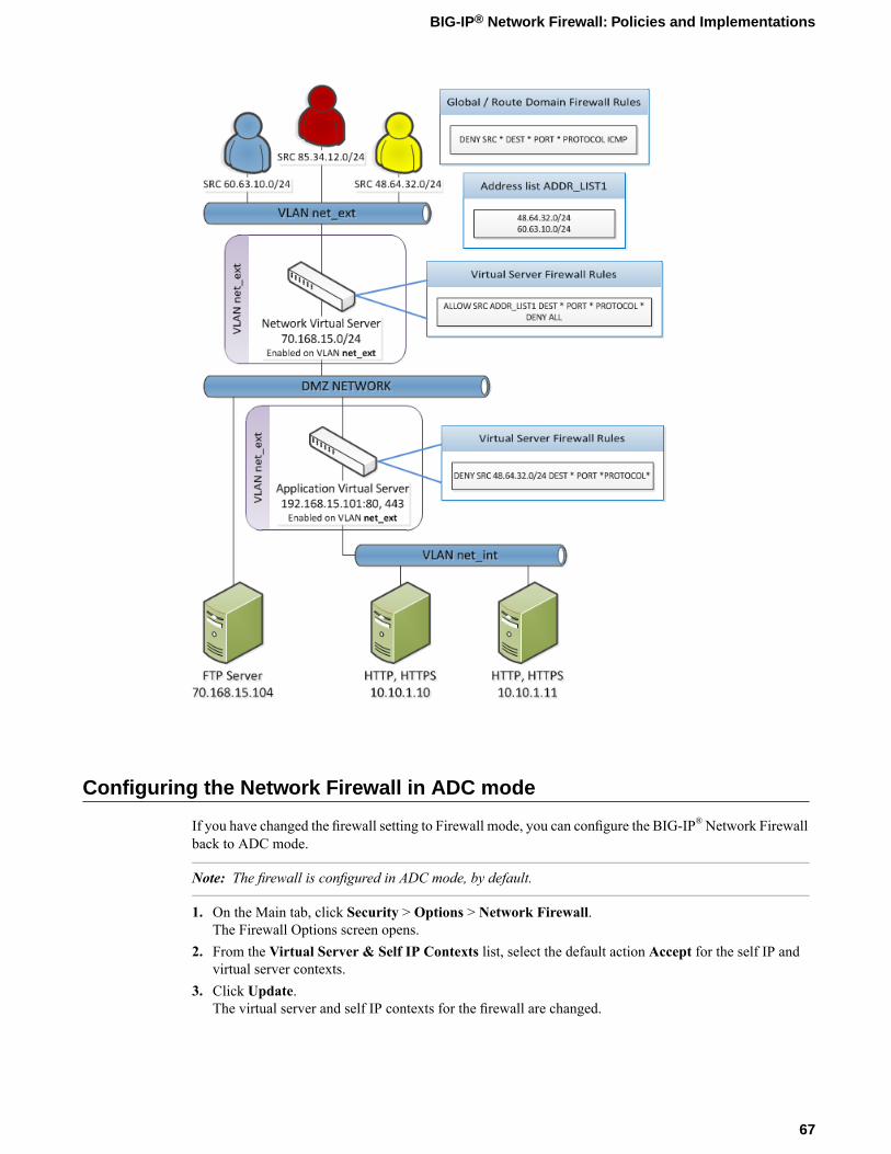
Configuring the Network Firewall in ADC mode
If you have changed the firewall setting to Firewall mode, you can configure the BIG-IP®Network Firewallback to ADC mode.
Note: The firewall is configured in ADC mode, by default.
1. On the Main tab, click Security > Options > Network Firewall.The Firewall Options screen opens.
2. From the Virtual Server & Self IP Contexts list, select the default action Accept for the self IP andvirtual server contexts.
3. Click Update.The virtual server and self IP contexts for the firewall are changed.
67
BIG-IP® Network Firewall: Policies and Implementations

Creating a VLAN for the network firewall
Create a VLAN with tagged interfaces, so that each of the specified interfaces can process traffic destinedfor that VLAN.
1. On the Main tab, click Network > VLANs.The VLAN List screen opens.
2. Click Create.The New VLAN screen opens.
3. In the Name field, type a unique name for the VLAN.For purposes of this implementation, name the VLAN net_ext.
4. For the Interfaces setting, click an interface number or trunk name from the Available list, and use theMove button to add the selected interface or trunk to the Tagged list. Repeat this step as necessary.You can use the same interface for other VLANs later, if you always assign the interface as a taggedinterface.
5. If you want the system to verify that the return route to an initial packet is the same VLAN from whichthe packet originated, select the Source Check check box.
6. From the Configuration list, select Advanced.7. In theMTU field, retain the default number of bytes (1500).8. If you want to base redundant-system failover on VLAN-related events, select the Fail-safe box.9. From the Auto Last Hop list, select a value.10. From the CMP Hash list, select a value.11. To enable the DAG Round Robin setting, select the check box.12. Click Finished.
The screen refreshes, and displays the new VLAN from the list.
The new VLAN appears in the VLAN list.
Enable the new VLAN on both the network virtual server and the application virtual server.
Configuring an LTM virtual server with a VLAN for Network Firewall
For this implementation, at least two virtual servers and one at least one VLAN are assumed, though yourconfiguration might be different.
You enable two virtual servers on the same VLAN to allow traffic from hosts on one virtual server to reachor pass through the other. In the Network Firewall, if you are using multiple virtual servers to allow or denytraffic to and from specific hosts behind different virtual servers, you must enable those virtual servers onthe same VLAN.
Tip: By default, the virtual server is set to share traffic on All VLANs and Tunnels. This configurationwill work for your VLANs, but in the firewall context specifying or limiting VLANs that can share trafficprovides greater security.
1. On the Main tab, click Local Traffic > Virtual Servers.The Virtual Server List screen opens.
2. Click the name of the virtual server you want to modify.
68
Deploying the BIG-IP Network Firewall in ADC Mode

3. From theVLANandTunnel Traffic list, selectEnabled on. Then, for theVLANs andTunnels setting,move the VLAN or VLANs on which you want to allow the virtual servers to share traffic from theAvailable list to the Selected list.
4. Click Update to save the changes.5. Repeat this task for all virtual servers that must share traffic over the VLAN.
The virtual servers on which you enabled the same VLAN can now pass traffic.
Adding a firewall rule to deny ICMP
Use this task to create a firewall rule at the Global context, that denies ICMP packets globally.
1. On the Main tab, click Security > Network Firewall > Active Rules.The Active Rules screen opens.
2. In the Rules area, click Add to add a firewall rule to the list.3. From the Context list, select the Global context.4. In the Name field, type deny_icmp.5. From the Type list, select Rule.6. From the State list, select Enabled.7. From the Protocol list, select ICMP.8. In the ICMP Message area, from the Type list, select Any, and click the Add button.
Tip: You can optionally deny only ICMP ping requests, by selecting Echo (8) from the Type list, andclicking Add.
9. Leave the Source area configured to allow Any address, port, and VLAN.10. Leave the Destination area configured to allow Any address or port.11. From the Action list, select Drop or Reject.
These options either drop ICMP packets from any source and port to any port and address, or send areject message and reset the the connection.
12. From the Logging list, enable or disable logging for the firewall rule.13. Click Finished.
The list screen and the new item are displayed.
A new firewall rule is created, and appears in the firewall rule list. This firewall rule denies all access toand from all sources and destinations on the ICMP protocol.
Creating an address list
Use this procedure to specify the address list to apply to allow access to specific source addresses.
1. On the Main tab, click Security > Network Firewall > Address Lists.The Address Lists screen opens.
2. Click Create to create a new address list.3. In the name field, type ADDR_LIST1.
69
BIG-IP® Network Firewall: Policies and Implementations

4. In the Addresses area, add the following addresses: 48.63.32.0/24 and 60.63.10.0/24. ClickAddafter you type each address.
5. Click Finished.The list screen and the new item are displayed.
Denying access with firewall rules on the network virtual server
The firewall rules in this example apply in the virtual server context. For purposes of this example, theexternal network-facing virtual server has an IP address of 70.168.15.0/24. The network virtual serveris configured with a pool that includes a publically accessible FTP server at 70.168.15.104, and anapplication virtual server at 192.168.15.101.
Use this task to create a firewall rule that allows all traffic from the networks on the address listADDR_LIST1, and another firewall rule that denies all traffic. This serves the purpose of allowing all trafficfrom the networks that are allowed access, and denying all other traffic.
1. On the Main tab, click Security > Network Firewall > Active Rules.The Active Rules screen opens.
2. In the Rules area, click Add to add a firewall rule to the list.3. Select the Virtual Server context, then select the external network virtual server (in this example,
70.168.15.0/24).4. In the Name field, type allow_addr_list.5. From the Type list, select Rule.6. From the State list, select Enabled.7. From the Protocol list, select Any.8. In the Source area, from the Address list, select List.9. From the Source Available list, select ADDR_LIST1, then click the << button to move ADDR_LIST1 to
the Selected list.10. Leave the Destination area configured with the default Any / Any settings.11. From the Action list, select Accept.
This allows packets from any source on the list to the any destination and port on any protocol on theDMZ network.
12. From the Logging list, enable or disable logging for the firewall rule.13. Click the Repeat button.
The rule is saved, and a new rule creation page opens, with the same information, so you can create asimilar rule.
14. In the Name field, type deny_all.15. In the Source area, in the Address list, select Any.16. Leave the Destination area configured to deny access to Any address or port.17. From the Action list, select Reject.
This creates a deny all rule for the virtual server.18. From the Logging list, enable or disable logging for the firewall rule.19. Click Finished.
The list screen and the new item are displayed.20. From the Context list, select Virtual Server.21. From the Virtual Server list, select the network virtual server.22. Click the Filter button.
70
Deploying the BIG-IP Network Firewall in ADC Mode

The list screen opens, and all firewall rules that apply to the virtual server are displayed.
Denying access with firewall rules on the application virtual server
The firewall rules in this example apply in the virtual server context. For purposes of this example, theapplication virtual server on the internal network has an IP address of 192.168.15.101, and is configuredto load balance traffic to servers 10.10.1.10 and 10.10.1.11 on ports 80 and 443.
Use this task to create a firewall rule that denies all traffic from the network 48.64.32.0/24 to the internalapplication servers behind the virtual server 192.168.15.101.
1. On the Main tab, click Security > Network Firewall > Active Rules.The Active Rules screen opens.
2. In the Rules area, click Add to add a firewall rule to the list.3. Select the Virtual Server context, then select the application virtual server (in this example,
192.168.15.101).4. In the Name field, type deny_network_485. From the Type list, select Rule.6. From the State list, select Enabled.7. From the Schedule list, select None.8. From the Protocol list, select Any.9. In the Source area, from the Address list, select Specify.10. In the address field, type 48.64.32.0/24.11. Leave the Destination area configured to deny access to Any address or port.12. From the Action list, select Drop or Reject.
This drops packets from the 48.64.32.0 network to any source.13. From the Logging list, enable or disable logging for the firewall rule.14. Click Finished.
The list screen and the new item are displayed.15. From the Context list, select Virtual Server.16. From the Virtual Server list, select the application virtual server.17. Click the Filter button.
The firewall rules are created, and are displayed on the list screen for the application virtual server.
71
BIG-IP® Network Firewall: Policies and Implementations


Chapter
10Deploying the BIG-IP Network Firewall in Firewall Mode
• About Firewall mode in the Network Firewall• Configuring the Network Firewall to drop
traffic that is not specifically allowed• Creating a VLAN for the network firewall• Creating an address list• Allowing access from networks on an
address list with a firewall rule• Allowing access from a network to a virtual
server with a firewall rule
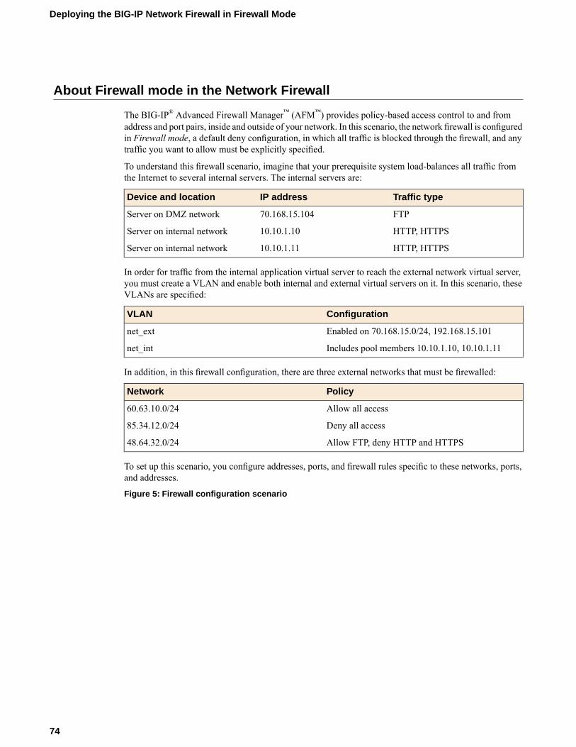
About Firewall mode in the Network Firewall
The BIG-IP® Advanced Firewall Manager™ (AFM™) provides policy-based access control to and fromaddress and port pairs, inside and outside of your network. In this scenario, the network firewall is configuredin Firewall mode, a default deny configuration, in which all traffic is blocked through the firewall, and anytraffic you want to allow must be explicitly specified.
To understand this firewall scenario, imagine that your prerequisite system load-balances all traffic fromthe Internet to several internal servers. The internal servers are:
Traffic typeIP addressDevice and location
FTP70.168.15.104Server on DMZ network
HTTP, HTTPS10.10.1.10Server on internal network
HTTP, HTTPS10.10.1.11Server on internal network
In order for traffic from the internal application virtual server to reach the external network virtual server,you must create a VLAN and enable both internal and external virtual servers on it. In this scenario, theseVLANs are specified:
ConfigurationVLAN
Enabled on 70.168.15.0/24, 192.168.15.101net_ext
Includes pool members 10.10.1.10, 10.10.1.11net_int
In addition, in this firewall configuration, there are three external networks that must be firewalled:
PolicyNetwork
Allow all access60.63.10.0/24
Deny all access85.34.12.0/24
Allow FTP, deny HTTP and HTTPS48.64.32.0/24
To set up this scenario, you configure addresses, ports, and firewall rules specific to these networks, ports,and addresses.
Figure 5: Firewall configuration scenario
74
Deploying the BIG-IP Network Firewall in Firewall Mode

Configuring the Network Firewall to drop traffic that is not specifically allowed
You can configure the BIG-IP® Network Firewall to deny all traffic not explicitly allowed. In AdvancedFirewall Manager™ this is called Firewall mode, and this is also referred to as a default deny policy. Firewallmode applies a default deny policy to all self IPs and virtual servers.
1. On the Main tab, click Security > Options > Network Firewall.The Firewall Options screen opens.
2. From the Virtual Server & Self IP Contexts list, select the default action Drop for the self IP andvirtual server contexts.
3. Click Update.The default virtual server and self IP firewall context is changed.
75
BIG-IP® Network Firewall: Policies and Implementations

If you are using ConfigSync to synchronize two or more devices, and you set the default action to Drop orReject, you must apply the built-in firewall rules _sys_self_allow_defaults or_sys_self_allow_management to the specific self IPs that are used to support those services. To dothis, add a new rule with the Self IP context, select the self IP, and select the Rule List rule type. Finally,select the preconfigured rules from the list of rule lists.
Creating a VLAN for the network firewall
Create a VLAN with tagged interfaces, so that each of the specified interfaces can process traffic destinedfor that VLAN.
1. On the Main tab, click Network > VLANs.The VLAN List screen opens.
2. Click Create.The New VLAN screen opens.
3. In the Name field, type a unique name for the VLAN.For purposes of this implementation, name the VLAN net_ext.
4. For the Interfaces setting, click an interface number or trunk name from the Available list, and use theMove button to add the selected interface or trunk to the Tagged list. Repeat this step as necessary.You can use the same interface for other VLANs later, if you always assign the interface as a taggedinterface.
5. If you want the system to verify that the return route to an initial packet is the same VLAN from whichthe packet originated, select the Source Check check box.
6. From the Configuration list, select Advanced.7. In theMTU field, retain the default number of bytes (1500).8. If you want to base redundant-system failover on VLAN-related events, select the Fail-safe box.9. From the Auto Last Hop list, select a value.10. From the CMP Hash list, select a value.11. To enable the DAG Round Robin setting, select the check box.12. Click Finished.
The screen refreshes, and displays the new VLAN from the list.
The new VLAN appears in the VLAN list.
Enable the new VLAN on both the network virtual server and the application virtual server.
Configuring an LTM virtual server with a VLAN for Network Firewall
For this implementation, at least two virtual servers and one at least one VLAN are assumed, though yourconfiguration might be different.
You enable two virtual servers on the same VLAN to allow traffic from hosts on one virtual server to reachor pass through the other. In the Network Firewall, if you are using multiple virtual servers to allow or denytraffic to and from specific hosts behind different virtual servers, you must enable those virtual servers onthe same VLAN.
76
Deploying the BIG-IP Network Firewall in Firewall Mode

Tip: By default, the virtual server is set to share traffic on All VLANs and Tunnels. This configurationwill work for your VLANs, but in the firewall context specifying or limiting VLANs that can share trafficprovides greater security.
1. On the Main tab, click Local Traffic > Virtual Servers.The Virtual Server List screen opens.
2. Click the name of the virtual server you want to modify.3. From theVLAN and Tunnel Traffic list, selectEnabled on. Then, for theVLANs and Tunnels setting,
move the VLAN or VLANs on which you want to allow the virtual servers to share traffic from theAvailable list to the Selected list.
4. Click Update to save the changes.5. Repeat this task for all virtual servers that must share traffic over the VLAN.
The virtual servers on which you enabled the same VLAN can now pass traffic.
Creating an address list
Use this procedure to specify the address list to apply to allow access to specific source addresses.
1. On the Main tab, click Security > Network Firewall > Address Lists.The Address Lists screen opens.
2. Click Create to create a new address list.3. In the name field, type ADDR_LIST1.4. In the Addresses area, add the following addresses: 48.63.32.0/24 and 60.63.10.0/24. ClickAdd
after you type each address.5. Click Finished.
The list screen and the new item are displayed.
Allowing access from networks on an address list with a firewall rule
The firewall rules in this example apply in the virtual server context. For purposes of this example, theexternal network-facing virtual server is named ex_VS and has an IP address of 70.168.15.0/24.
Create a firewall rule that allows traffic from the networks on ADDR_LIST1 to the DMZ network, whichincludes an FTP server that is publicly addressed, and two internal servers on a second virtual server.
1. On the Main tab, click Security > Network Firewall > Active Rules.The Active Rules screen opens.
2. In the Rules area, click Add to add a firewall rule to the list.3. From theContext list, selectVirtual Server, and then select the external virtual server (in the example,
ex_VS).4. In the Name field, type allow_addr_list.5. From the Type list, select Rule.6. From the State list, select Enabled.7. From the Protocol list, select Any.
77
BIG-IP® Network Firewall: Policies and Implementations

8. In the Source area, from the Address list, select Specify, and click Address List.9. From the list, select /Common/ADDR_LIST1, then click Add to add ADDR_LIST1 to the list.10. Leave the Destination area configured with the default Any / Any settings.11. From the Action list, select Accept.
This allows packets from any source on the list to the any destination and port on any protocol on theDMZ network.
12. From the Logging list, enable or disable logging for the firewall rule.13. Click Finished.
The list screen and the new item are displayed.
A new firewall rule is created, and appears in the firewall rule list.
Allowing access from a network to a virtual server with a firewall rule
The firewall rules in this example apply in the virtual server context. For purposes of this example, theapplication virtual server is behind the network virtual server with an IP address of 192.168.15.101 andconfigured for traffic on ports 80 and 443.
Use this procedure to create a firewall rule that allows traffic from a specific external network to the HTTPand HTTPS servers behind an application virtual server.
1. On the Main tab, click Security > Network Firewall > Active Rules.The Active Rules screen opens.
2. In the Rules area, click Add to add a firewall rule to the list.3. In the Context field, select Virtual Server, and select the application virtual server (in the example,
192.168.15.101.4. In the Name field, type allow_app_vs.5. From the Type list, select Rule.6. From the State list, select Enabled.7. From the Protocol list, select Any.8. In the Source area, from the Address list, select Specify.9. In the address field, type 60.63.10.0/24, then click the Add button.10. Leave the Destination area configured with the default Any / Any settings.11. From the Action list, select Accept.
This allows packets from the specified source to any destination and port on any protocol on the internalvirtual server. You could specify HTTP and HTTPS protocols, and the internal server addresses, butsince these are the only addresses and protocols behind the virtual server, that level of granularity is notnecessary.
12. From the Logging list, enable or disable logging for the firewall rule.13. Click Finished.
The list screen and the new item are displayed.
A new firewall rule is created, and appears in the firewall rule list.
78
Deploying the BIG-IP Network Firewall in Firewall Mode

Chapter
11Configuring BIG-IP Network Firewall Policies
• About firewall policies• About firewall policy compilation• Viewing enforced and staged policy rule logs

About firewall policies
The BIG-IP® Network Firewall policies combine one or more inline rules or rule lists, and apply them as acombined policy to one or more contexts. Such policies are applied to a context directly, and cannot coexistin that context with inline rules. You can configure a context to use either a specific firewall policy or inlinerules, but not both. A firewall policy and inline rules are mutually exclusive of each other. However, firewallcontext precedence does apply, so inline rules at the global context, for example, apply even if they contradictrules applied at a lower precedence context; for example, at a virtual server.
You can apply a network firewall policy as a staged policy, while continuing to enforce existing inline rules,or you can apply one firewall policy while staging another policy. A staged policy allows you to evaluatethe effect a policy has on traffic by analyzing the system logs, without actually modifying traffic based onthe firewall rules.
Creating a Network Firewall policy
Use this procedure to create a BIG-IP® Network Firewall policy.
1. On the Main tab, click Security > Network Firewall > Policies.The Policies screen opens.
2. Click Create to create a new policy.3. Type a name and optional description for the firewall policy.4. Click Finished.
The Policies screen shows the new policy in the policy list.
Define firewall rules and rule lists for the policy to make it function.
Creating a Network Firewall policy rule
If you are going to specify address lists or port lists to use with this rule, you must create these lists beforecreating the firewall policy rule, or add them after you save the policy rule.
Create a network firewall policy rule to manage access from an IP or web network address to a specifiednetwork location, server, or address behind a BIG-IP® system.
Note: You cannot add rules created with this task to a rule list at a later time. You must create rules for arule list from within the rule list. Similarly, you cannot use the rules created in a policy to apply as inlinerules in another context, though you can use rule lists in a policy rule.
1. On the Main tab, click Security > Network Firewall > Policies.The Policies screen opens.
2. Click the name of the network firewall policy to which you want to add rules.3. In the Rules area, click Add to add a firewall rule to the list.4. From the Type list, select whether you are creating a standalone network firewall policy rule or creating
a rule list.If you create a firewall policy rule list, only the Name, Description, and Stateoptions apply, and youmust select or create a rule list to include.
5. From the Order list, select an order modifier.
80
Configuring BIG-IP Network Firewall Policies
You can add the rule before or after an existing rule, or you can add it first or last in the rule list. Rulesare added in the last position by default.
6. In the Name and Description fields, type the name and an optional description.7. From the State list, select the rule state.
• Select Enabled to apply the firewall policy rule to the addresses and ports specified.• Select Disabled to set the firewall policy rule to not apply at all.• Select Scheduled to apply the firewall policy according to the selected schedule.
8. From the Protocol list, select the protocol to which the firewall rule applies.
• Select Any to apply the firewall rule to any protocol.• Select the protocol name to apply the rule to a single protocol.
Important: ICMP is handled by the BIG-IP system at the global or route domain level. Because of this,ICMP messages receive a response before they reach the virtual server context. You cannot create aninline rule for ICMP or ICMPv6 on a Self IP context. You can apply a rule list to a self IP that includesa rule for ICMP or ICMPv6; however, such a rule will be ignored. To apply firewall actions to the ICMPprotocol, create a rule with the global or route domain context. ICMP rules are evaluated only forICMP forwarding requests, and not for the IP addresses of the BIG-IP system itself.
Note: Note that you must select a protocol if you specify ports.
9. From the Source Address/Region list, select the type of source address to which this rule applies.
• Select Any to have the rule apply to any packet source IP address.• Select Specify and click Address to specify one or more packet source IP addresses to which the
rule applies. When selected, you can type single IP addresses into the Address field, then clickAddto add them to the address list.
• Select Specify and clickAddress List to select a predefined list of packet source addresses to whichthe rule applies. To use an address list with this rule, select the address list and click the Add button.Similarly, to remove the list from this rule, select the list and click the Delete button.
• Select Specify and clickAddress Range to specify a contiguous range of packet source IP addressesto which the rule applies. When selected, you can type a start and end IP address in the fields, thenclick Add to add the IP address range to the address list.
• Select Specify and click Country/Region to identify the geographic origin of packet sources, andto apply rules based on selected geographic locations. When selected, a field appears in which youcan select a country. For many countries, an extra field appears after you select the country, in whichyou can select a state or province. If you do not select a specific state or province, the entire countryis selected. After you select a geographic location, click Add to add it to the Source address list.
10. From the Source Port list, select the type of packet source ports to which this rule applies.
• Select Any to have the rule apply to any packet source port.• Select Specify and click Port to specify one or more packet source ports to which the rule applies.
When selected, you can type single port numbers into the Port field, then click Add to add them tothe port list.
• Select Specify and click Port Range to specify a list of contiguous packet source port numbers towhich the rule applies. When selected, you can type the start and end ports into the fields, then clickAdd to add the ports to the port list.
• Select Specify and click Port List to select a predefined list of packet source ports to which the ruleapplies. To use a port list with this rule, select the port list and click the Add button. Similarly, toremove the list from this rule, select the list and click the Delete button.
11. From the Source VLAN/Tunnel list, select the VLAN on which this rule applies.
81
BIG-IP® Network Firewall: Policies and Implementations

• Select Any to have the rule apply to traffic on any VLAN through which traffic enters the firewall.• Select Specify to specify one or more VLANs on the firewall to which the rule applies. To use a
VLAN with this rule, move the VLAN from the Available list to the Selected list by clicking the<< button. Similarly, to remove the VLAN from this rule, click the >> button to move the VLANfrom the Selected list to the Available list.
12. From the Destination Address/Region list, select the type of packet destination address to which thisrule applies.
• Select Any to have the rule apply to any IP packet destination address.• Select Specify and click Address to specify one or more packet destination IP addresses to which
the rule applies. When selected, you can type single IP addresses into the Address field, then clickAdd to add them to the address list.
• Select Specify and click Address List to select a predefined list of packet destination addresses towhich the rule applies. To use an address list with this rule, select the address list and click the Addbutton. Similarly, to remove the list from this rule, select the list and click the Delete button.
• Select Specify and click Address Range to specify a contiguous range of packet destination IPaddresses to which the rule applies. When selected, you can type a start and end IP address in thefields, then click Add to add the IP address range to the address list.
• Select Specify and clickCountry/Region to identify the geographic packet destination, and to applyrules based on specific geographic locations. When selected, a field appears in which you can selecta country. For many countries, an extra field appears after you select the country, in which you canselect a state or province. If you do not select a specific state or province, the entire country is selected.After you select a geographic location, click Add to add it to the Destination address list.
13. From the Destination Port list, select the type of packet destination ports to which this rule applies.
• Select Any to have the rule apply to any port inside the firewall.• Select Specify and click Port to specify one or more packet destination ports to which the rule
applies. When selected, you can type single port numbers into the Port field, then click Add to addthem to the port list.
• Select Specify and click Port Range to specify a list of contiguous packet destination port numbersto which the rule applies. When selected, you can type the start and end ports into the fields, thenclick Add to add the ports to the port list.
• Select Specify and click Port List to select a predefined list of packet destination ports to which therule applies. To use a port list with this rule, select the port list and click the Add button. Similarly,to remove the list from this rule, select the list and click the Delete button.
14. Optionally, from the iRule list, select an iRule to start if the rule matches traffic.15. From the Action list, select the firewall action for traffic originating from the specified source address
on the specified protocol. Choose from one of the these actions:DescriptionOption
Allows packets with the specified source, destination, and protocol to pass throughthe firewall. Packets that match the rule, and are accepted, traverse the system as ifthe firewall is not present.
Accept
Allows packets with the specified source, destination, and protocol to pass throughthe firewall, and does not require any further processing by any of the further
AcceptDecisively
firewalls. Packets that match the rule, and are accepted, traverse the system as ifthe firewall is not present.
Drops packets with the specified source, destination, and protocol. Dropping apacket is a silent action with no notification to the source or destination systems.
Drop
Dropping the packet causes the connection to be retried until the retry threshold isreached.
82
Configuring BIG-IP Network Firewall Policies

DescriptionOption
Rejects packets with the specified source, destination, and protocol. When a packetis rejected the firewall sends a destination unreachable message to the sender.
Reject
16. From the Logging list, enable or disable logging for the firewall rule.17. Click Finished.
The list screen and the new item are displayed.
The new firewall policy rule is created.
Setting a global firewall policy
You can create a virtual server with a firewall policy, to provide policy-based network firewall actions atthe virtual server.
1. On the Main tab, click Security > Network Firewall > Active Rules.The Active Rules screen opens.
2. Under Active Network Firewall Rules, click the Global link.The Global Firewall Rules screen opens.
3. To enforce rules from a firewall policy in the selected context, in the Network Firewall area, from theEnforcement list, select Policy Rules, then select the firewall policy to enforce from the Policy list.
4. To stage rules from a firewall policy in the selected context, in the Network Firewall area, from theStaging list, select Enabled, then select the firewall policy to stage from the Policy list.
The policy rules you selected are enforced at the global level. If you chose to stage policy rules, the resultsof those rules are logged, but not enforced.
Configuring a route domain with a firewall policy
Before you can configure a route domain with a firewall policy, you need a pre-existing route domain.
On a route domain, you can set firewall policies for enforcement and staging. Use this task to set firewallpolicies on an existing route domain. You create a route domain on BIG-IP® system to segment (isolate)traffic on your network. Route domains are useful for multi-tenant configurations.
1. On the Main tab, click Network > Route Domains.The Route Domain List screen opens.
2. Click the name of the route domain to show the route domain configuration.3. Click on the Security tab.4. To enforce rules from a firewall policy on the route domain, in the Network Firewall area, from the
Enforcement list, select Policy Rules, then select the firewall policy to enforce from the Policy list.5. To stage rules from a firewall policy on the route domain, in the Network Firewall area, from the Staging
list, select Enabled, then select the firewall policy to stage from the Policy list.6. To enforce any inline rules that apply to the route domain, and not apply a firewall policy, in the Network
Firewall area, from the Enforcement list, select Inline Rules.7. Click Update to save the changes to the route domain.
Now, you have configured a route domain on the BIG-IP system, with either firewall policies or inline rulesenforced at the route domain context.
83
BIG-IP® Network Firewall: Policies and Implementations

Setting network firewall policies for a self IP address
Ensure that you have created a self IP address.
You can configure network firewall rules at a self IP address by inline rule, or you can enforce a firewallpolicy. You can also stage a firewall policy to check the effect without affecting traffic.
1. On the Main tab, click Network > Self IPs.The Self IPs screen opens.
2. Click on the self IP address to which you want to add a network firewall policy.3. Click the Security tab.4. To enforce rules from a firewall policy on the self IP, in the Network Firewall area, from theEnforcement
list, select Policy Rules, then select the firewall policy to enforce from the Policy list.5. To stage rules from a firewall policy on the self IP, in the Network Firewall area, from the Staging list,
select Enabled, then select the firewall policy to stage from the Policy list.6. To enforce any inline rules that apply to the self IP, and not apply a firewall policy, in the Network
Firewall area, from the Enforcement list, select Inline Rules.7. Click Update to save the changes to the self IP.
The selected self IP now enforces or stages rules according to your selections.
Creating a virtual server with a firewall policy
You can create a virtual server with a firewall policy, to provide policy-based network firewall actions atthe virtual server.
1. On the Main tab, click Local Traffic > Virtual Servers.The Virtual Server List screen opens.
2. Click the Create button.The New Virtual Server screen opens.
3. In the Name field, type a unique name for the virtual server.4. For the Destination setting, in the Address field, type the IP address you want to use for the virtual
server.The IP address you type must be available and not in the loopback network.
5. In the Service Port field, type * or select * All Ports from the list.6. Click Finished.7. Click the name of the virtual server you want to modify.8. On the menu bar, click Security > Policies.
The screen displays Policy settings and Inline Rules settings.9. To enforce rules from a firewall policy on the virtual server, in the Network Firewall area, from the
Enforcement list, select Policy Rules, then select the firewall policy to enforce from the Policy list.10. To stage rules from a firewall policy on the virtual server, in the Network Firewall area, from the Staging
list, select Enabled, then select the firewall policy to stage from the Policy list.11. Click Update to save the changes.
The policy rules you selected are enforced on the virtual server. If you chose to stage policy rules, the resultsof those rules are logged, but not enforced.
84
Configuring BIG-IP Network Firewall Policies

About firewall policy compilation
When you apply a rule list or policy to a context, the rule list or policy requires some server resources tocompile. You can view the resources used on a context for the last rule compilation, by viewing compilerstatistics on the context page. Compiler statistics are displayed for several items.
Activation TimeDisplays the time at which firewall policies or rule lists were last activated on this context.
Compilation DurationDisplays the amount of time required to compile the rule sets or policies at the last activation.
Compilation SizeDisplays the file size of the compiled rule sets or policies, after the last activation.
Maximum Transient MemoryDisplays the maximum memory used to compile the rule sets or policies during the last activation.
Viewing compilation statistics for a firewall rule or policy
You can view the most recent compilation statistics for a rule list or policy on the Global Context, or on aRoute Domain, Self IP, or Virtual Server context.
1. On the Main tab, click Security > Network Firewall > Active Rules.The Active Rules screen opens.
2. From the Context list, select All.3. Click on the name of the context for which you want to view statistics.
For example, the Global Context is always called Global. A virtual server or self IP has the name youassigned when you created it; for example, vs_http_134 or self_lb_11 . A route domain is identifiedwith a number; for example, 0.
4. View statistics for rule compilation.
• In the Global Context, from the Policy Settings list, select Advanced.• In a Route Domain, Self IP, or Virtual Server context, click the Security tab. Then, from the Policy
Settings list, select Advanced.
Statistics are displayed for the most recent rule list and policy compilation on the selected context.
Viewing enforced and staged policy rule logs
With BIG-IP® Advanced Firewall Manager™, you can choose to enforce either inline firewall rules or afirewall policy for a specific context. You can also choose to stage policies for a specific context. Stagedpolicies apply all of the specified firewall rules to the policy context, but do not enforce the firewall action.Therefore, the result of a staged policy is informational only, and the result can be analyzed in the firewalllogs.
A staged policy on a particular context might not behave the same after you change it to an enforcementpolicy. Because there can be multiple staged policies on different contexts, the staged policy results you
85
BIG-IP® Network Firewall: Policies and Implementations

see (in logs and stats) are actually the aggregate of all staged policies on all contexts. Thus, if you enforcea previously staged policy on one or more contexts, but other staged policies remain on other contexts thatyou do not enforce, the actual enforced results might differ from what you expected from viewing logs andstatistics for staged rules.
Important: You must enable logging for a policy, if you want to view the results of staged or enforced rulesin the logs.
Viewing Network Firewall enforced policy events on the local BIG-IP system
Ensure that the BIG-IP® system is configured to log the types of events you want to view, and to store thelog messages locally on the BIG-IP system.
When the BIG-IP system is configured to log events locally, you can view those events using theConfiguration utility.
1. On the Main tab, click Security > Event Logs > Network > Firewall.The Network Firewall event log displays.
2. To search for enforced policy events, in the search field, type Enforced, then click Search.3. To narrow your search for enforced events, click Custom Search. Drag the Enforced text from the
Policy Type column to the custom search table. Narrow your search further by dragging other itemsfrom the log display, for example, from the action, policy, or rule columns. the event data that you wantto search for from the Event Log table into the Custom Search table, and then click Search.
Viewing Network Firewall staged policy events on the local BIG-IP system
Ensure that the BIG-IP® system is configured to log the types of events you want to view, and to store thelog messages locally on the BIG-IP system.
When the BIG-IP system is configured to log events locally, you can view those events using theConfiguration utility.
Important: You must enable logging for a policy, if you want to view the results of staged or enforced rulesin the logs.
1. On the Main tab, click Security > Event Logs > Network > Firewall.The Network Firewall event log displays.
2. To search for staged policy events, in the search field, type Staged, then click Search.3. To narrow your search for staged policy events, click Custom Search. Drag the Staged text from the
Policy Type column to the custom search table. Narrow your search further by dragging other itemsfrom the log display. For example, from the action, policy, or rule columns, you can drag event datathat you want to search for from the Event Log table into the Custom Search table, and then click Search.
86
Configuring BIG-IP Network Firewall Policies

Chapter
12About HTTP Protocol Security
• Overview: Securing HTTP traffic• Creating an HTTP virtual server with protocol
security• Attaching an HTTP protocol security profile
to a virtual server• Reviewing violation statistics for security
profiles• Overview: Creating a custom HTTP security
profile• Overview: Increasing HTTP traffic security• About RFC compliance and validation checks• About evasion techniques checks• About the types of HTTP request checks• Configuring the blocking response page for
HTTP security profiles• Overview: Configuring Local Protocol
Security Event Logging• Task summary• Implementation result• Overview: Configuring Remote Protocol
Security Event Logging• Implementation result

Overview: Securing HTTP traffic
You can secure HTTP traffic by using a default configuration or by customizing the configuration. You canadjust the following security checks in an HTTP security profile:
• HTTP protocol compliance validation• Evasion technique detection• Length checking to help avoid buffer overflow attacks• HTTP method validation• Inclusion or exclusion of certain files by type• Mandatory header enforcement
You can also specify how you want the system to respond when it encounters a violation. If the systemdetects a violation and you enabled the Block flag, instead of forwarding the request, the system can eithersend a blocking response page or redirect the client to a different location.
Creating an HTTP virtual server with protocol security
When you enable protocol security for an HTTP virtual server, the system scans any incoming HTTP trafficfor vulnerabilities before the traffic reaches the HTTP servers.
1. On the Main tab, click Local Traffic > Virtual Servers.The Virtual Server List screen opens.
2. Click the Create button.The New Virtual Server screen opens.
3. In the Name field, type a unique name for the virtual server.4. For the Destination setting, in the Address field, type the IP address you want to use for the virtual
server.The IP address you type must be available and not in the loopback network.
5. In the Service Port field, type 80 (for HTTP) or 443 (for HTTPS), or select HTTP or HTTPS fromthe list.
6. In the Configuration area, for the HTTP Profile setting, select the default profile, http.7. From the Source Address Translation list, select Auto Map.8. For the Default Pool setting, either select an existing pool from the list, or click the Create (+) button
and create a new pool.9. Click Finished.
The HTTP virtual server appears in the Virtual Servers list.
Attaching an HTTP protocol security profile to a virtual server
The easiest method for adding HTTP protocol security to your HTTP virtual server is to use the systemdefault profile. You do this by configuring a virtual server with theHTTP profile http, and then associatingthe default HTTP protocol security profile http_security with the virtual server.
88
About HTTP Protocol Security

1. On the Main tab, click Local Traffic > Virtual Servers.The Virtual Server List screen opens.
2. In the Name column, click the virtual server you previously created.The Properties screen for the virtual server opens.
3. From the Security menu, choose Policies.4. From the Protocol Security list, select Enabled.5. From the Profile list, select http_security.
This configures the virtual server with the default HTTP protocol security profile.
6. Click Update.
You now have a virtual server configured so that HTTP protocol checks are performed on the traffic thatthe HTTP virtual server receives.
Reviewing violation statistics for security profiles
You can view statistics and transaction information for each security profile that triggers security violations.
1. On the Main tab, click Security > Event Logs > Protocol and click HTTP, FTP, SMTP, or DNS.The appropriate statistics screen opens listing all violations for that protocol, with the number ofoccurrences.
2. Type a Support ID, if you have one, to filter the violations and view one in particular.3. Click a violation's hyperlink to see details about the requests causing the violation.
On the Statistics screen, in the left column, you can review information regarding the traffic volume foreach security profile configured.
Overview: Creating a custom HTTP security profile
This implementation describes how to set up the BIG-IP® system to perform security checks on your HTTPvirtual server traffic customized to the needs of your environment. Custom configuration of HTTP securityand traffic management requires creating an HTTP service profile with security, and fine tuning this profileso it protects HTTP traffic the way you want. Once you have all HTTP settings specified, you create avirtual server using the HTTP custom service profile, and a default pool to handle the HTTP traffic.
Task summaryCreating a custom HTTP profileCreating a security profile for HTTP trafficConfiguring an HTTP virtual server with an HTTP security profileReviewing violation statistics for security profiles
Creating a custom HTTP profile
An HTTP profile defines the way that you want the BIG-IP®system to manage HTTP traffic.
89
BIG-IP® Network Firewall: Policies and Implementations
1. On the Main tab, click Local Traffic > Profiles > Services > HTTP.The HTTP profile list screen opens.
2. Click Create.The New HTTP Profile screen opens.
3. In the Name field, type a unique name for the profile.4. From the Parent Profile list, select http.5. Select the Custom check box.6. Modify the settings, as required.7. Click Finished.
The custom HTTP profile now appears in the HTTP profile list screen.
Creating a security profile for HTTP traffic
Before performing this procedure, verify that you have installed and provisioned BIG-IP®Advanced FirewallManager™ (AFM) on the BIG-IP system.
AnHTTP security profile specifies security checks that apply to HTTP traffic, and that you want the BIG-IP®
system to enforce. In the security profile, you can also configure remote logging and trusted XFF headers.
1. On the Main tab, click Security > Protocol Security > Security Profiles > HTTP.The Security Profiles: HTTP screen opens.
2. Click the Create button.The New HTTP Security Profile screen opens.
3. In the Profile Name field, type a unique name for the profile.4. If you want the system to trust XFF (X-Forwarded-For) headers in the requests:
a) Select the Trust XFF Header check box.Select this option if the BIG-IP system is deployed behind an internal or other trusted proxy. Then,the system uses the IP address that initiated the connection to the proxy instead of the internal proxy’sIP address.The screen refreshes and provides an additional setting.
b) In the New Custom XFF Header field, type the header that you want the system to trust, then clickAdd.You can add up to five custom XFF headers.
5. If you want the security profile to be case-sensitive, leave the Profile is case sensitive check box selected.Otherwise, clear the check box.
Note: You cannot change this setting after you create the security profile.
6. Modify the blocking policy settings by clickingHTTPProtocol Checks andRequest Checks, selectingthe appropriate options, and enabling the Block or Alarm options as needed.
Note: If you do not enable either Alarm or Block for a protocol check, the system does not perform thecorresponding security verification.
• Alarm: The system logs any requests that trigger the security profile violation.• Block: The system blocks any requests that trigger the security profile violation.• Alarm and Block: The system both logs and blocks any requests that trigger the security profile
violation.
90
About HTTP Protocol Security

7. Click Blocking Page if you want to configure the blocking response page.8. Click Create.
The screen refreshes, and you see the new security profile in the list.
The BIG-IP® system automatically assigns this service profile to HTTP traffic that a designated virtualserver receives.
Configuring an HTTP virtual server with an HTTP security profile
You can configure a local traffic virtual server and a default pool for your network's HTTP servers. Whenthe virtual server receives HTTP traffic, an HTTP security profile can scan for security vulnerabilities, andload balance traffic that passes the scan.
1. On the Main tab, click Local Traffic > Virtual Servers.The Virtual Server List screen opens.
2. Click the Create button.The New Virtual Server screen opens.
3. In the Name field, type a unique name for the virtual server.4. In the Service Port field, type 443 or select HTTPS from the list.5. From the HTTP Profile list, select the http profile .6. In the Resources area of the screen, for the Default Pool setting, click the Create (+) button.
The New Pool screen opens.7. In the Name field, type a unique name for the pool.8. In the Resources area, for the New Members setting, select the type of new member you are adding,
then type the appropriate information in the Node Name, Address, and Service Port fields, and clickAdd to add as many pool members as you need.
9. Click Finished to create the pool.The screen refreshes, and reopens the New Virtual Server screen. The new pool name appears in theDefault Pool list.
10. Click Finished to create the virtual server.The screen refreshes, and you see the new virtual server in the list.
11. In the Name column, click the name of the relevant virtual server.This displays the properties of the virtual server.
12. From the Security menu, choose Policies.13. From the Protocol Security list, select Enabled.14. From the Protocol Security Profile list, select your custom HTTP security profile.15. Click Update to save the changes.
Reviewing violation statistics for security profiles
You can view statistics and transaction information for each security profile that triggers security violations.
1. On the Main tab, click Security > Event Logs > Protocol and click HTTP, FTP, SMTP, or DNS.The appropriate statistics screen opens listing all violations for that protocol, with the number ofoccurrences.
2. Type a Support ID, if you have one, to filter the violations and view one in particular.3. Click a violation's hyperlink to see details about the requests causing the violation.
91
BIG-IP® Network Firewall: Policies and Implementations

On the Statistics screen, in the left column, you can review information regarding the traffic volume foreach security profile configured.
Overview: Increasing HTTP traffic security
The HTTP security profile consists of many different security checks for the various components of HTTPtraffic. This implementation shows you how to fine-tune your HTTP security profile as required by yourenvironment. The custom checks are described under the assumption that you have already created a customHTTP security profile but have no other prerequisite or special order. You need configure only the customchecks that you are interested in.
You can achieve a greater level of security when you configure the system to perform the following checks:
• HTTP Protocol Checks that are related to RFC compliance and actions to take resulting from a violation• Request Checks, such as length, allowable HTTP request methods, inclusion or exclusion of file types,
and custom headers that must occur in every request• Blocking Page configuration which describes the page to display in the event of a blocked request when
a violation is encountered
About RFC compliance and validation checks
When the BIG-IP® system receives an HTTP request from a client, the first validation check that the systemperforms is to ensure that it is RFC protocol compliant. If the request passes the compliance checks, thesystem applies the security profile to the request. So that your system fully validates RFC compliance, keepthe following HTTP Protocol Checks enabled (they are enabled by default):
• Several Content-Length headers: This security check fails when the incoming request contains morethan one content-length header.
• Null in request: This security check fails when the incoming request contains a null character.• Unparsable request content: This security check fails when the Advanced Firewall Manager™ is unable
to parse the incoming request.
Modifying HTTP protocol compliance checks
F5 Networks® recommends that you retain the default properties for the HTTP protocol security checks.This task allows you to take additional precautions such as enabling the Block flag for the HTTP ProtocolChecks setting, even if you enable only the Alarm flag for the other security checks. When you do this, thesystem blocks all requests that are not compliant with HTTP protocol standards, and performs additionalsecurity checks only on valid HTTP traffic.
1. On the Main tab, click Security > Protocol Security > Security Profiles > HTTP.The Security Profiles: HTTP screen opens.
2. In the HTTP Security Profiles area, in the Profile Name column, click the name of the security profilethat you are modifying.The HTTP Profile Properties screen opens.
3. On the HTTP Protocol Checks tab, for the HTTP Protocol Checks setting, select the check boxes forthe protocol checks that you want the system to validate.
92
About HTTP Protocol Security

4. Select Alarm or Block to indicate how you want the system to respond to a triggered violation.The default setting is Alarm.
• Alarm: The system logs any requests that trigger the violation.• Block: The system blocks any requests that trigger the violation.• Alarm and Block: The system both logs and blocks any requests that trigger the violation.
5. Click Update to retain changes.
The BIG-IP® system is now enabled for compliance checks on all valid HTTP traffic.
About evasion techniques checks
Advanced FirewallManager™ can examineHTTP requests for methods of application attack that are designedto avoid detection. When found, these coding methods, called evasion techniques, trigger the Evasiontechnique detected violation. By creating HTTP security profiles, you can detect evasion techniques, suchas:
• Directory traversal, for example, a/b/../c turns into a/c• Multiple decoding passes• Multiple backslash characters in a URI, for example, \\servername• Bare byte decoding (higher than ASCII-127) in a URI• Apache whitespace characters (0x09, 0x0b, or 0x0c)
• Bad unescape
By default, the system logs requests that contain evasion techniques. You can also block requests that includeevasion techniques.
Configuring HTTP protocol evasion techniques blocking policy
You can use HTTP security profiles to detect, log, alarm, and block evasion techniques detected in HTTPtraffic.
1. On the Main tab, click Security > Protocol Security > Security Profiles > HTTP.The Security Profiles: HTTP screen opens.
2. In the HTTP Security Profiles area, in the Profile Name column, click the name of the security profilethat you are modifying.The HTTP Profile Properties screen opens.
3. On the HTTP Protocol Checks tab, for the Evasion Techniques Checks setting, select or clear theAlarm or Block check boxes, as required.
DescriptionOption
The system logs any requests that trigger the violation. This is the defaultsetting.
Alarm
The system blocks any requests that trigger the violation.Block
The system both logs and blocks any requests that trigger the violation.Alarm and Block
4. Click Update to retain changes.
93
BIG-IP® Network Firewall: Policies and Implementations
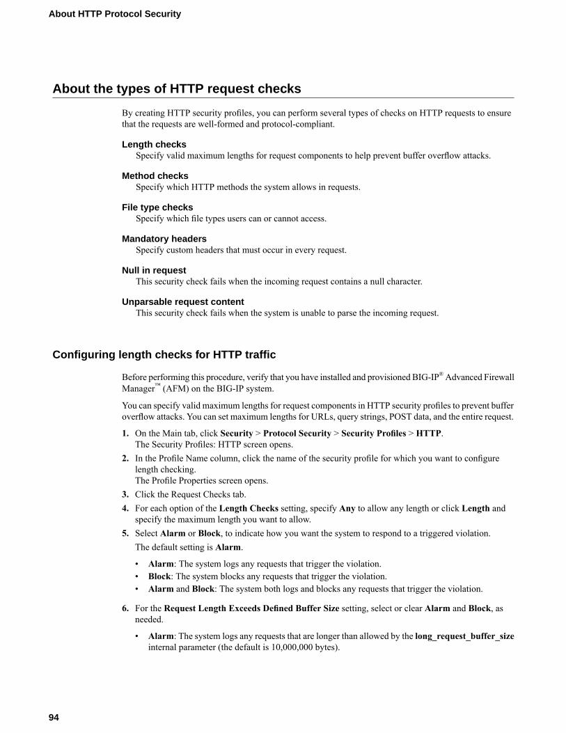
About the types of HTTP request checks
By creating HTTP security profiles, you can perform several types of checks on HTTP requests to ensurethat the requests are well-formed and protocol-compliant.
Length checksSpecify valid maximum lengths for request components to help prevent buffer overflow attacks.
Method checksSpecify which HTTP methods the system allows in requests.
File type checksSpecify which file types users can or cannot access.
Mandatory headersSpecify custom headers that must occur in every request.
Null in requestThis security check fails when the incoming request contains a null character.
Unparsable request contentThis security check fails when the system is unable to parse the incoming request.
Configuring length checks for HTTP traffic
Before performing this procedure, verify that you have installed and provisioned BIG-IP®Advanced FirewallManager™ (AFM) on the BIG-IP system.
You can specify valid maximum lengths for request components in HTTP security profiles to prevent bufferoverflow attacks. You can set maximum lengths for URLs, query strings, POST data, and the entire request.
1. On the Main tab, click Security > Protocol Security > Security Profiles > HTTP.The Security Profiles: HTTP screen opens.
2. In the Profile Name column, click the name of the security profile for which you want to configurelength checking.The Profile Properties screen opens.
3. Click the Request Checks tab.4. For each option of the Length Checks setting, specify Any to allow any length or click Length and
specify the maximum length you want to allow.5. Select Alarm or Block, to indicate how you want the system to respond to a triggered violation.
The default setting is Alarm.
• Alarm: The system logs any requests that trigger the violation.• Block: The system blocks any requests that trigger the violation.• Alarm and Block: The system both logs and blocks any requests that trigger the violation.
6. For the Request Length Exceeds Defined Buffer Size setting, select or clear Alarm and Block, asneeded.
• Alarm: The system logs any requests that are longer than allowed by the long_request_buffer_sizeinternal parameter (the default is 10,000,000 bytes).
94
About HTTP Protocol Security
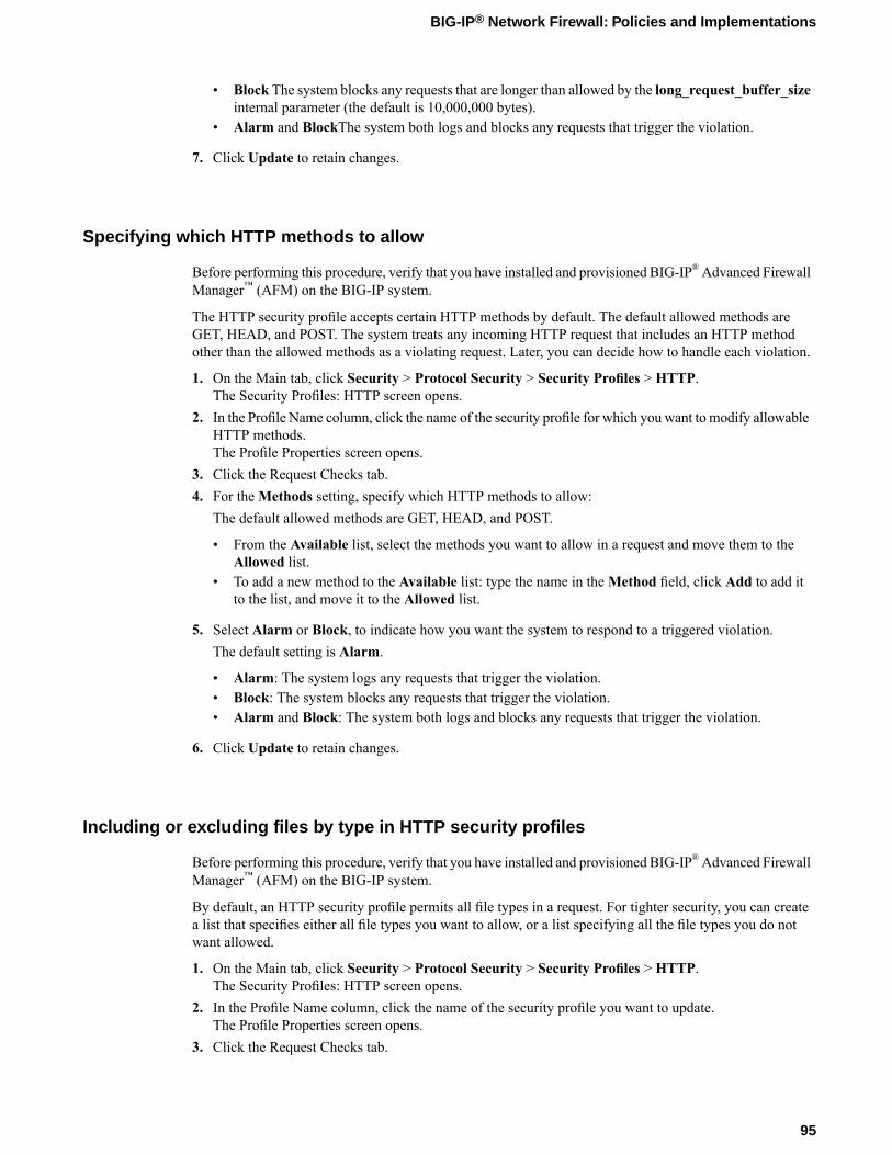
• Block The system blocks any requests that are longer than allowed by the long_request_buffer_sizeinternal parameter (the default is 10,000,000 bytes).
• Alarm and BlockThe system both logs and blocks any requests that trigger the violation.
7. Click Update to retain changes.
Specifying which HTTP methods to allow
Before performing this procedure, verify that you have installed and provisioned BIG-IP®Advanced FirewallManager™ (AFM) on the BIG-IP system.
The HTTP security profile accepts certain HTTP methods by default. The default allowed methods areGET, HEAD, and POST. The system treats any incoming HTTP request that includes an HTTP methodother than the allowed methods as a violating request. Later, you can decide how to handle each violation.
1. On the Main tab, click Security > Protocol Security > Security Profiles > HTTP.The Security Profiles: HTTP screen opens.
2. In the Profile Name column, click the name of the security profile for which you want to modify allowableHTTP methods.The Profile Properties screen opens.
3. Click the Request Checks tab.4. For theMethods setting, specify which HTTP methods to allow:
The default allowed methods are GET, HEAD, and POST.
• From the Available list, select the methods you want to allow in a request and move them to theAllowed list.
• To add a new method to the Available list: type the name in theMethod field, click Add to add itto the list, and move it to the Allowed list.
5. Select Alarm or Block, to indicate how you want the system to respond to a triggered violation.The default setting is Alarm.
• Alarm: The system logs any requests that trigger the violation.• Block: The system blocks any requests that trigger the violation.• Alarm and Block: The system both logs and blocks any requests that trigger the violation.
6. Click Update to retain changes.
Including or excluding files by type in HTTP security profiles
Before performing this procedure, verify that you have installed and provisioned BIG-IP®Advanced FirewallManager™ (AFM) on the BIG-IP system.
By default, an HTTP security profile permits all file types in a request. For tighter security, you can createa list that specifies either all file types you want to allow, or a list specifying all the file types you do notwant allowed.
1. On the Main tab, click Security > Protocol Security > Security Profiles > HTTP.The Security Profiles: HTTP screen opens.
2. In the Profile Name column, click the name of the security profile you want to update.The Profile Properties screen opens.
3. Click the Request Checks tab.
95
BIG-IP® Network Firewall: Policies and Implementations

4. For the File Types setting, specify whether you want to create a list of allowed or disallowed file types,and which files you want in the list.
• To create a list of file types that are permitted in requests, select Define Allowed.• To create a list of file types not permitted, select Define Disallowed.• Select file types from the Available list, and move them to the Allowed or Disallowed list.• To add a new file type, type the name in the File Type field, click Add to add it to the Available
list, and then move it to the Allowed or Disallowed list.
Important: If the profile is case-sensitive, the file types are case-sensitive. For example, jsp and JSPwill be treated as separate file types.
5. Select Alarm or Block, to indicate how you want the system to respond to a triggered violation.The default setting is Alarm.
• Alarm: The system logs any requests that trigger the violation.• Block: The system blocks any requests that trigger the violation.• Alarm and Block: The system both logs and blocks any requests that trigger the violation.
The page you configured is displayed every time one of the security checks set to Block has been violated.
Configuring a mandatory header for an HTTP security profile
Before performing this procedure, verify that you have installed and provisioned BIG-IP®Advanced FirewallManager™ (AFM) on the BIG-IP system.
When the BIG-IP® system is managing an application that uses custom headers that must occur in everyrequest, you can specify mandatory HTTP headers in the security profile. The system verifies that all requestscontain those headers. If a request does not contain the mandatory header, the system issues the MandatoryHTTP header is missing violation, and takes the action that you configure: Alarm, Block, or both.
1. On the Main tab, click Security > Protocol Security > Security Profiles > HTTP.The Security Profiles: HTTP screen opens.
2. In the Profile Name column, click the name of the security profile for which you want to configure aMandatory Header alarm.The Profile Properties screen opens.
3. Click the Request Checks tab.4. For theMandatory Headers setting, specify the header that must be in the request:
a) In the Header field, type the name of the mandatory header, and click the Add button to add it tothe Available list.
b) Move the new mandatory header from the Available list to theMandatory list.c) Select or clear the Alarm or Block check boxes as required.
DescriptionOptionThe system logs any responses that trigger theMandatory HTTP headeris missing violation. This is the default setting.
Alarm
The system blocks any requests that trigger theMandatory HTTP headeris missing violation.
Block
The system both logs and blocks any requests that trigger theMandatoryHTTP header is missing violation.
Alarm and Block
96
About HTTP Protocol Security

5. Click Update to retain changes.
All HTTP requests are checked for the mandatory headers you have selected.
Configuring the blocking response page for HTTP security profiles
If your HTTP security profile is set up to block requests that violate one or more of the security checks, thesystem displays a page, called the blocking response page, on the client's screen. The default blockingresponse page states that the request was rejected, and provides a support ID. You can also configure thesystem to redirect the client to a specific web site instead of displaying the blocking response page.
1. On the Main tab, click Security > Protocol Security > Security Profiles > HTTP.The Security Profiles: HTTP screen opens.
2. In the Profile Name column, click the name of the security profile for which you want to configure ablocking page.The Profile Properties screen opens.
3. Click the Blocking Page tab.4. For the Response Type setting, select one of the options:
• Default Response: Specifies that the system returns the system-supplied blocking response page.Though you cannot edit the HTML code on the default blocking page, you can copy it into a customresponse and edit it.
• Custom Response: Specifies that the system returns a response page that you design or upload.• Redirect URL: Specifies that the system redirects the client to the specified URL.• SOAP Fault: Specifies that the system displays a blocking page in standard SOAP fault message
format. Though you cannot edit the SOAP fault code, you can copy it into a custom response andedit it.
The settings on the screen change depending on the selection that you make for the Response Typesetting.
5. If you selected the Custom Response option, you can either create a new response or upload an HTMLfile.
• To create a custom response, make the changes you want to the default responses for the ResponseHeader and Response Body settings using HTTP syntax for the content, and click Upload.
• To upload an HTML file for the response body, navigate to an existing HTML response page, andclick Upload.
6. If you selected Redirect URL, type the full path of the web page to which the system should redirectthe client in the Redirect URL field.
7. Click Update to retain changes.
The system displays the response page when a violation occurs on any of the security checks set to Block.
Overview: Configuring Local Protocol Security Event Logging
You can configure the BIG-IP® system to log detailed information about protocol security events and storethose logs locally.
97
BIG-IP® Network Firewall: Policies and Implementations

Important: The BIG-IP Advanced Firewall Manager™ (AFM) must be licensed and provisioned and DNSServices must be licensed before you can configure Protocol Security event logging.
Task summary
Perform these tasks to configure Protocol Security event logging locally on the BIG-IP® system.
Note: Enabling logging and storing the logs locally impacts BIG-IP system performance.
Creating a local Protocol Security Logging profileConfiguring a virtual server for Protocol Security event loggingViewing Protocol Security event logs locally on the BIG-IP systemDisabling logging
Creating a local Protocol Security Logging profile
Create a custom Logging profile to log BIG-IP system network firewall events locally on the BIG-IP system.
1. On the Main tab, click Security > Event Logs > Logging Profiles.The Logging Profiles list screen opens.
2. Click Create.The New Logging Profile screen opens.
3. In the Profile Name field, type a unique name for the profile.4. Select the Protocol Security check box, to enable the BIG-IP system to log HTTP, FTP, DNS, and
SMTP protocol request events.5. In the HTTP, FTP, and SMTP Security area, from the Publisher list, select local-db-publisher.6. In the DNS Security area, from the Publisher list, select local-db-publisher.7. Select the Log Dropped DNS Requests check box, to enable the BIG-IP system to log dropped DNS
requests.8. Select the Log Filtered Dropped DNS Requests check box, to enable the BIG-IP system to log DNS
requests dropped due to DNS query/header-opcode filtering.
Note: The system does not log DNS requests that are dropped due to errors in the way the systemprocesses DNS packets.
9. Select the Log Malformed DNS Requests check box, to enable the BIG-IP system to log malformedDNS requests.
10. Select the Log Rejected DNS Requests check box, to enable the BIG-IP system to log rejected DNSrequests.
11. Select the LogMalicious DNS Requests check box, to enable the BIG-IP system to log malicious DNSrequests.
12. Click Finished.
Assign this custom protocol security Logging profile to a virtual server.Task summary
98
About HTTP Protocol Security

Configuring a virtual server for Protocol Security event logging
Ensure that at least one Log Publisher exists on the BIG-IP® system.
Assign a custom Protocol Security Logging profile to a virtual server when you want the BIG-IP system tolog Protocol Security events on the traffic the virtual server processes.
Note: This task applies only to systems provisioned at a minimum level (or higher) for Local Traffic (LTM).You can check the provisioning level on the System > Resource Provisioning screen.
1. On the Main tab, click Local Traffic > Virtual Servers.The Virtual Server List screen opens.
2. Click the name of the virtual server you want to modify.3. On the menu bar, click Security > Policies.
The screen displays Policy settings and Inline Rules settings.4. From the Log Profile list, select Enabled. Then, for the Profile setting, move the profiles that log
specific events to specific locations from the Available list to the Selected list.5. Click Update to save the changes.
Task summary
Viewing Protocol Security event logs locally on the BIG-IP system
Ensure that the BIG-IP® system is configured to log the types of events you want to view, and to store thelog messages locally on the BIG-IP system.
When the BIG-IP system is configured to log events locally, you can view those events using theConfiguration utility.
1. On the Main tab, click Security > Event Logs > Protocol > DNS.The Protocol Security event log displays.
2. To search for specific events, click Custom Search. Drag the event data that you want to search forfrom the Event Log table into the Custom Search table, and then click Search.
Task summary
Disabling logging
Disable Network Firewall, Protocol Security, or DoS Protection event logging when you no longer wantthe BIG-IP® system to log specific events on the traffic handled by specific resources.
Note: You can disable and re-enable logging for a specific resource based on your network administrationneeds.
1. On the Main tab, click Local Traffic > Virtual Servers.The Virtual Server List screen opens.
2. Click the name of the virtual server you want to modify.3. On the menu bar, click Security > Policies.
The screen displays Policy settings and Inline Rules settings.
99
BIG-IP® Network Firewall: Policies and Implementations
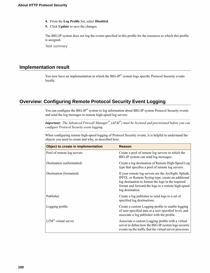
4. From the Log Profile list, select Disabled.5. Click Update to save the changes.
The BIG-IP system does not log the events specified in this profile for the resources to which this profileis assigned.
Task summary
Implementation result
You now have an implementation in which the BIG-IP® system logs specific Protocol Security eventslocally.
Overview: Configuring Remote Protocol Security Event Logging
You can configure the BIG-IP® system to log information about BIG-IP system Protocol Security eventsand send the log messages to remote high-speed log servers.
Important: The Advanced Firewall Manager™ (AFM™) must be licensed and provisioned before you canconfigure Protocol Security event logging.
When configuring remote high-speed logging of Protocol Security events, it is helpful to understand theobjects you need to create and why, as described here:
ReasonObject to create in implementation
Create a pool of remote log servers to which theBIG-IP system can send log messages.
Pool of remote log servers
Create a log destination of Remote High-Speed Logtype that specifies a pool of remote log servers.
Destination (unformatted)
If your remote log servers are the ArcSight, Splunk,IPFIX, or Remote Syslog type, create an additional
Destination (formatted)
log destination to format the logs in the requiredformat and forward the logs to a remote high-speedlog destination.
Create a log publisher to send logs to a set ofspecified log destinations.
Publisher
Create a custom Logging profile to enable loggingof user-specified data at a user-specified level, andassociate a log publisher with the profile.
Logging profile
Associate a custom Logging profile with a virtualserver to define how the BIG-IP system logs securityevents on the traffic that the virtual server processes.
LTM® virtual server
100
About HTTP Protocol Security
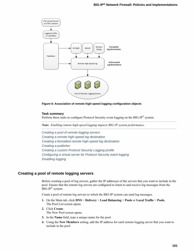
Figure 6: Association of remote high-speed logging configuration objects
Task summaryPerform these tasks to configure Protocol Security event logging on the BIG-IP® system.
Note: Enabling remote high-speed logging impacts BIG-IP system performance.
Creating a pool of remote logging serversCreating a remote high-speed log destinationCreating a formatted remote high-speed log destinationCreating a publisherCreating a custom Protocol Security Logging profileConfiguring a virtual server for Protocol Security event loggingDisabling logging
Creating a pool of remote logging servers
Before creating a pool of log servers, gather the IP addresses of the servers that you want to include in thepool. Ensure that the remote log servers are configured to listen to and receive log messages from theBIG-IP® system.
Create a pool of remote log servers to which the BIG-IP system can send log messages.
1. On the Main tab, click DNS > Delivery > Load Balancing > Pools or Local Traffic > Pools.The Pool List screen opens.
2. Click Create.The New Pool screen opens.
3. In the Name field, type a unique name for the pool.4. Using the New Members setting, add the IP address for each remote logging server that you want to
include in the pool:
101
BIG-IP® Network Firewall: Policies and Implementations

a) Type an IP address in the Address field, or select a node address from the Node List.b) Type a service number in the Service Port field, or select a service name from the list.
Note: Typical remote logging servers require port 514.
c) Click Add.
5. Click Finished.
Creating a remote high-speed log destination
Before creating a remote high-speed log destination, ensure that at least one pool of remote log serversexists on the BIG-IP® system.
Create a log destination of theRemote High-Speed Log type to specify that log messages are sent to a poolof remote log servers.
1. On the Main tab, click System > Logs > Configuration > Log Destinations.The Log Destinations screen opens.
2. Click Create.3. In the Name field, type a unique, identifiable name for this destination.4. From the Type list, select Remote High-Speed Log.
Important: If you use log servers such as Remote Syslog, Splunk, or ArcSight, which require data besent to the servers in a specific format, you must create an additional log destination of the requiredtype, and associate it with a log destination of theRemote High-Speed Log type. With this configuration,the BIG-IP system can send data to the servers in the required format.
The BIG-IP system is configured to send an unformatted string of text to the log servers.5. From the Pool Name list, select the pool of remote log servers to which you want the BIG-IP system
to send log messages.6. From the Protocol list, select the protocol used by the high-speed logging pool members.7. Click Finished.
Creating a formatted remote high-speed log destination
Ensure that at least one remote high-speed log destination exists on the BIG-IP® system.
Create a formatted logging destination to specify that log messages are sent to a pool of remote log servers,such as Remote Syslog, Splunk, or ArcSight servers.
1. On the Main tab, click System > Logs > Configuration > Log Destinations.The Log Destinations screen opens.
2. Click Create.3. In the Name field, type a unique, identifiable name for this destination.4. From the Type list, select a formatted logging destination, such as IPFIX, Remote Syslog, Splunk, or
ArcSight.
102
About HTTP Protocol Security
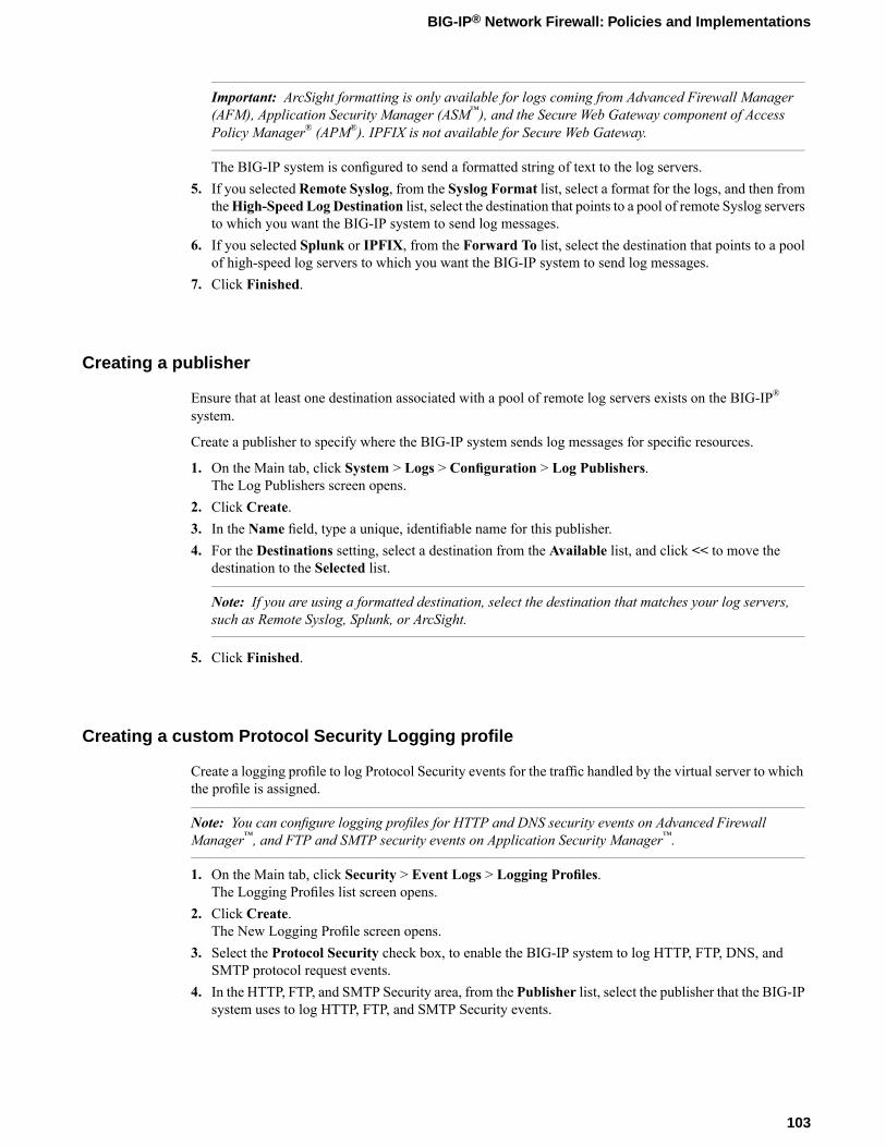
Important: ArcSight formatting is only available for logs coming from Advanced Firewall Manager(AFM), Application Security Manager (ASM™), and the Secure Web Gateway component of AccessPolicy Manager® (APM®). IPFIX is not available for Secure Web Gateway.
The BIG-IP system is configured to send a formatted string of text to the log servers.5. If you selectedRemote Syslog, from the Syslog Format list, select a format for the logs, and then from
theHigh-Speed Log Destination list, select the destination that points to a pool of remote Syslog serversto which you want the BIG-IP system to send log messages.
6. If you selected Splunk or IPFIX, from the Forward To list, select the destination that points to a poolof high-speed log servers to which you want the BIG-IP system to send log messages.
7. Click Finished.
Creating a publisher
Ensure that at least one destination associated with a pool of remote log servers exists on the BIG-IP®
system.
Create a publisher to specify where the BIG-IP system sends log messages for specific resources.
1. On the Main tab, click System > Logs > Configuration > Log Publishers.The Log Publishers screen opens.
2. Click Create.3. In the Name field, type a unique, identifiable name for this publisher.4. For the Destinations setting, select a destination from the Available list, and click << to move the
destination to the Selected list.
Note: If you are using a formatted destination, select the destination that matches your log servers,such as Remote Syslog, Splunk, or ArcSight.
5. Click Finished.
Creating a custom Protocol Security Logging profile
Create a logging profile to log Protocol Security events for the traffic handled by the virtual server to whichthe profile is assigned.
Note: You can configure logging profiles for HTTP and DNS security events on Advanced FirewallManager™, and FTP and SMTP security events on Application Security Manager™.
1. On the Main tab, click Security > Event Logs > Logging Profiles.The Logging Profiles list screen opens.
2. Click Create.The New Logging Profile screen opens.
3. Select the Protocol Security check box, to enable the BIG-IP system to log HTTP, FTP, DNS, andSMTP protocol request events.
4. In the HTTP, FTP, and SMTP Security area, from the Publisher list, select the publisher that the BIG-IPsystem uses to log HTTP, FTP, and SMTP Security events.
103
BIG-IP® Network Firewall: Policies and Implementations

5. In the DNS Security area, from the Publisher list, select the publisher that the BIG-IP system uses tolog DNS Security events.
6. Select the Log Dropped DNS Requests check box, to enable the BIG-IP system to log dropped DNSrequests.
7. Select the Log Filtered Dropped DNS Requests check box, to enable the BIG-IP system to log DNSrequests dropped due to DNS query/header-opcode filtering.
Note: The system does not log DNS requests that are dropped due to errors in the way the systemprocesses DNS packets.
8. Select the Log Malformed DNS Requests check box, to enable the BIG-IP system to log malformedDNS requests.
9. Select the Log Rejected DNS Requests check box, to enable the BIG-IP system to log rejected DNSrequests.
10. Select the LogMalicious DNS Requests check box, to enable the BIG-IP system to log malicious DNSrequests.
11. From the Storage Format list, select how the BIG-IP system formats the log. Your choices are:DescriptionOption
Specifies the default format type in which the BIG-IP system logs messages to aremote Syslog server, for example:
None
"management_ip_address","bigip_hostname","context_type","context_name","src_ip","dest_ip","src_port","dest_port","vlan","protocol","route_domain","acl_rule_name","action","drop_reason
This option allows you to:Field-List
• Select from a list, the fields to be included in the log.• Specify the order the fields display in the log.• Specify the delimiter that separates the content in the log. The default delimiter
is the comma character.
This option allows you to:User-Defined
• Select from a list, the fields to be included in the log.• Cut and paste, in a string of text, the order the fields display in the log.
12. Click Finished.
Assign this custom Protocol Security Logging profile to a virtual server.
Configuring a virtual server for Protocol Security event logging
Ensure that at least one Log Publisher exists on the BIG-IP® system.
Assign a custom Protocol Security Logging profile to a virtual server when you want the BIG-IP system tolog Protocol Security events on the traffic the virtual server processes.
Note: This task applies only to systems provisioned at a minimum level (or higher) for Local Traffic (LTM).You can check the provisioning level on the System > Resource Provisioning screen.
1. On the Main tab, click Local Traffic > Virtual Servers.The Virtual Server List screen opens.
104
About HTTP Protocol Security

2. Click the name of the virtual server you want to modify.3. On the menu bar, click Security > Policies.
The screen displays Policy settings and Inline Rules settings.4. From the Log Profile list, select Enabled. Then, for the Profile setting, move the profiles that log
specific events to specific locations from the Available list to the Selected list.5. Click Update to save the changes.
Task summary
Disabling logging
Disable Network Firewall, Protocol Security, or DoS Protection event logging when you no longer wantthe BIG-IP® system to log specific events on the traffic handled by specific resources.
Note: You can disable and re-enable logging for a specific resource based on your network administrationneeds.
1. On the Main tab, click Local Traffic > Virtual Servers.The Virtual Server List screen opens.
2. Click the name of the virtual server you want to modify.3. On the menu bar, click Security > Policies.
The screen displays Policy settings and Inline Rules settings.4. From the Log Profile list, select Disabled.5. Click Update to save the changes.
The BIG-IP system does not log the events specified in this profile for the resources to which this profileis assigned.
Task summary
Implementation result
You now have an implementation in which the BIG-IP® system logs specific Protocol Security events andsends the logs to a specific location.
105
BIG-IP® Network Firewall: Policies and Implementations


Appendix
AIPFIX Templates for AFM Events
• Overview: IPFIX Templates for AFM Events• About IPFIX Information Elements for AFM
events• About individual IPFIX templates for each
event

Overview: IPFIX Templates for AFM Events
The IP Flow Information Export (IPFIX) Protocol is a logging mechanism for IP events. This appendixdefines the IPFIX Information Elements (IEs) and Templates used to log F5’s Application FirewallManager(AFM) events. An IE is the smallest form of useful information in an IPFIX log message, such as an IPaddress or a timestamp for the event. An IPFIX template is an ordered collection of specific IEs used torecord one IP event, such as the acceptance of a network packet.
About IPFIX Information Elements for AFM events
Information Elements (IEs) are individual fields in an IPFIX template. An IPFIX template describes a singleAdvanced Firewall Manager™(AFM™) event.
IANA-defined IPFIX Information Elements
IANAmaintains a list of standard IPFIX Information Elements (IEs), each with a unique Element Identifier.The F5® AFM™ IPFIX implementation uses a subset of these IEs to publish AFM events. This subset issummarized in the table.
IANA IDSize (Bytes)Information Element (IE)
124destinationIPv4Address
2816destinationIPv6Address
112destinationTransportPort
2344ingressVRFID
3238observationTimeMilliseconds
41protocolIdentifier
84sourceIPv4Address
2716sourceIPv6Address
72sourceTransportPort
IPFIX enterprise Information Elements
IPFIX provides for enterprises to define their own Information Elements. F5® currently uses the followingnon-standard IEs for AFM™ events:
Size (Bytes)Information Element (IE)
VariableaclPolicyName
VariableaclPolicyType
VariableaclRuleName
Variableaction
108
IPFIX Templates for AFM Events
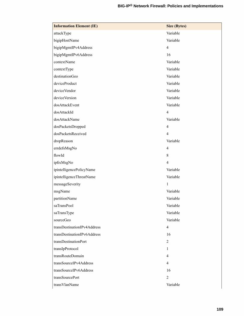
Size (Bytes)Information Element (IE)
VariableattackType
VariablebigipHostName
4bigipMgmtIPv4Address
16bigipMgmtIPv6Address
VariablecontextName
VariablecontextType
VariabledestinationGeo
VariabledeviceProduct
VariabledeviceVendor
VariabledeviceVersion
VariabledosAttackEvent
4dosAttackId
VariabledosAttackName
4dosPacketsDropped
4dosPacketsReceived
VariabledropReason
4errdefsMsgNo
8flowId
4ipfixMsgNo
VariableipintelligencePolicyName
VariableipintelligenceThreatName
1messageSeverity
VariablemsgName
VariablepartitionName
VariablesaTransPool
VariablesaTransType
VariablesourceGeo
4transDestinationIPv4Address
16transDestinationIPv6Address
2transDestinationPort
1transIpProtocol
4transRouteDomain
4transSourceIPv4Address
16transSourceIPv6Address
2transSourcePort
VariabletransVlanName
109
BIG-IP® Network Firewall: Policies and Implementations

Size (Bytes)Information Element (IE)
VariablevlanName
Note: IPFIX, unlike NetFlow v9, supports variable-length IEs, where the length is encoded within the fieldin the Data Record. NetFlow v9 collectors (and their variants) cannot correctly process variable-lengthIEs, so they are omitted from logs sent to those collector types.
About individual IPFIX templates for each event
F5® uses IPFIX templates to publish AFM™ events.
Network accept or deny
This IPFIX template is used whenever a network packet is accepted or denied by an AFM™ firewall.
NotesSize (Bytes)Information Element (IE)
This IE is omitted for NetFlow v9.VariableaclPolicyName
This IE is omitted for NetFlow v9.VariableaclPolicyType
This IE is omitted for NetFlow v9.VariableaclRuleName
This IE is omitted for NetFlow v9.Variableaction
This IE is omitted for NetFlow v9.VariablebigipHostName
4bigipMgmtIPv4Address
16bigipMgmtIPv6Address
This IE is omitted for NetFlow v9.VariablecontextName
This IE is omitted for NetFlow v9.VariablecontextType
8observationTimeMilliseconds
This IE is omitted for NetFlow v9.VariabledestinationGeo
4destinationIPv4Address
16destinationIPv6Address
2destinationTransportPort
This IE is omitted for NetFlow v9.VariabledeviceProduct
This IE is omitted for NetFlow v9.VariabledeviceVendor
This IE is omitted for NetFlow v9.VariabledeviceVersion
This IE is omitted for NetFlow v9.VariabledropReason
This IE is omitted for NetFlow v9.VariablemsgName
4errdefsMsgNo
8flowId
4ipfixMsgNo
110
IPFIX Templates for AFM Events

NotesSize (Bytes)Information Element (IE)
1protocolIdentifier
1messageSeverity
This IE is omitted for NetFlow v9.VariablepartitionName
4ingressVRFID
This IE is omitted for NetFlow v9.VariablesaTransPool
This IE is omitted for NetFlow v9.VariablesaTransType
This IE is omitted for NetFlow v9.VariablesourceGeo
4sourceIPv4Address
16sourceIPv6Address
2sourceTransportPort
4transDestinationIPv4Address
16transDestinationIPv6Address
2transDestinationPort
1transIpProtocol
4transRouteDomain
4transSourceIPv4Address
16transSourceIPv6Address
2transSourcePort
This IE is omitted for NetFlow v9.VariabletransVlanName
This IE is omitted for NetFlow v9.VariablevlanName
DoS device
NotesSize (Bytes)Information Element (IE)
This IE is omitted for NetFlow v9.Variableaction
This IE is omitted for NetFlow v9.VariablebigipHostName
4bigipMgmtIPv4Address
16bigipMgmtIPv6Address
This IE is omitted for NetFlow v9.VariablecontextName
8observationTimeMilliseconds
4destinationIPv4Address
16destinationIPv6Address
2destinationTransportPort
This IE is omitted for NetFlow v9.VariabledeviceProduct
This IE is omitted for NetFlow v9.VariabledeviceVendor
This IE is omitted for NetFlow v9.VariabledeviceVersion
111
BIG-IP® Network Firewall: Policies and Implementations
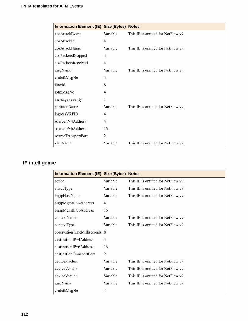
NotesSize (Bytes)Information Element (IE)
This IE is omitted for NetFlow v9.VariabledosAttackEvent
4dosAttackId
This IE is omitted for NetFlow v9.VariabledosAttackName
4dosPacketsDropped
4dosPacketsReceived
This IE is omitted for NetFlow v9.VariablemsgName
4errdefsMsgNo
8flowId
4ipfixMsgNo
1messageSeverity
This IE is omitted for NetFlow v9.VariablepartitionName
4ingressVRFID
4sourceIPv4Address
16sourceIPv6Address
2sourceTransportPort
This IE is omitted for NetFlow v9.VariablevlanName
IP intelligence
NotesSize (Bytes)Information Element (IE)
This IE is omitted for NetFlow v9.Variableaction
This IE is omitted for NetFlow v9.VariableattackType
This IE is omitted for NetFlow v9.VariablebigipHostName
4bigipMgmtIPv4Address
16bigipMgmtIPv6Address
This IE is omitted for NetFlow v9.VariablecontextName
This IE is omitted for NetFlow v9.VariablecontextType
8observationTimeMilliseconds
4destinationIPv4Address
16destinationIPv6Address
2destinationTransportPort
This IE is omitted for NetFlow v9.VariabledeviceProduct
This IE is omitted for NetFlow v9.VariabledeviceVendor
This IE is omitted for NetFlow v9.VariabledeviceVersion
This IE is omitted for NetFlow v9.VariablemsgName
4errdefsMsgNo
112
IPFIX Templates for AFM Events

NotesSize (Bytes)Information Element (IE)
8flowId
4ipfixMsgNo
This IE is omitted for NetFlow v9.VariableipintelligencePolicyName
This IE is omitted for NetFlow v9.VariableipintelligenceThreatName
1protocolIdentifier
1messageSeverity
This IE is omitted for NetFlow v9.VariablepartitionName
4ingressVRFID
This IE is omitted for NetFlow v9.VariablesaTransPool
This IE is omitted for NetFlow v9.VariablesaTransType
4sourceIPv4Address
16sourceIPv6Address
2sourceTransportPort
4transDestinationIPv4Address
16transDestinationIPv6Address
2transDestinationPort
1transIpProtocol
4transRouteDomain
4transSourceIPv4Address
16transSourceIPv6Address
2transSourcePort
This IE is omitted for NetFlow v9.VariabletransVlanName
This IE is omitted for NetFlow v9.VariablevlanName
113
BIG-IP® Network Firewall: Policies and Implementations

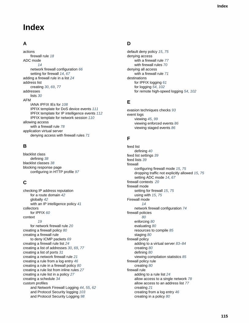
Index
A
actionsfirewall rule 18
ADC mode14
network firewall configuration 66setting for firewall 14, 67
adding a firewall rule in a list 24address list
creating 30, 69, 77addresses
lists 30AFM
IANA IPFIX IEs for 108IPFIX template for DoS device events 111IPFIX template for IP intelligence events 112IPFIX template for network session 110
allowing accesswith a firewall rule 78
application virtual serverdenying access with firewall rules 71
B
blacklist classdefining 38
blacklist classes 38blocking response page
configuring in HTTP profile 97
C
checking IP address reputationfor a route domain 42globally 42with an IP intelligence policy 41
collectorsfor IPFIX 60
context19
for network firewall rule 20creating a firewall policy 80creating a firewall rule
to deny ICMP packets 69creating a firewall rule list 24creating a list of addresses 30, 69, 77creating a list of ports 31creating a network firewall rule 21creating a rule from a log entry 46creating a rule in a firewall policy 80creating a rule list from inline rules 27creating a rule list in a policy 27creating a schedule 34custom profiles
and Network Firewall Logging 44, 55, 62and Protocol Security logging 103and Protocol Security Logging 98
D
default deny policy 15, 75denying access
with a firewall rule 77with firewall rules 70
denying all accesswith a firewall rule 71
destinationsfor IPFIX logging 61for logging 54, 102for remote high-speed logging 54, 102
E
evasion techniques checks 93event logs
viewing 45, 99viewing enforced events 86viewing staged events 86
F
feed listdefining 40
feed list settings 39feed lists 39firewall
configuring firewall mode 15, 75dropping traffic not explicitly allowed 15, 75setting ADC mode 14, 67
firewall contexts 20firewall mode
setting for firewall 15, 75using with 15, 75
Firewall mode14
network firewall configuration 74firewall policies
80enforcing 80evaluating 80resources to compile 85staging 80
firewall policyadding to a virtual server 83–84creating 80defining 80viewing compilation statistics 85
firewall policy rulecreating 80
firewall ruleadding to a rule list 24allow access to a single network 78allow access to an address list 77creating 21creating from a log entry 46creating in a policy 80
115
Index

firewall rule (continued)denying access to specific servers 70denying ICMP packets 69
firewall rule listcreating 24
firewall rulesactions 18context ordering 19denying access to specific networks 71
G
global actionsallowing traffic 14dropping traffic 14rejecting traffic 14
global contextassigning IP intelligence policy 42viewing compilation statistics 85
H
high-speed loggingand server pools 53, 101
HTTPand evasion techniques checks 93configuring request checks 94
HTTP profilesattaching security profile 88configuring mandatory headers 96configuring the blocking response page 97creating 89
HTTP protocol validationchecking, importance 92
HTTP request checksallowing or disallowing files by type 95configuring length checks 94specifying HTTP methods to allow 95
HTTP RFC complianceensuring in HTTP traffic 92
HTTP securityfine-tuning profile settings 92increasing 92
HTTP security profilesallowing files by type 95configuring length checks 94creating 89disallowing files by type 95fine-tuning 92specifying allowable methods 95
HTTP trafficblocking evasion techniques 93configuring protocol compliance checks 92creating security profile 90securing 88
I
interfacestagging 68, 76
IP addresschecking reputation 41
IP address intelligenceassigning globally 42assigning to a route domain 42assigning to a virtual server 42categories 37checking IP reputation 41creating a blacklist class 38creating a feed list 40downloading the database 36enabling 36feed lists 39
IP intelligence 36IP intelligence database 37IP intelligence policy
creating 41IPFIX
AFM template overview 108and server pools 60template for accept or deny through AFM firewall session110template for DoS device events 111template for IP intelligence events 112
IPFIX collectorsand destinations for log messages 61and publishers for log messages 61
IPFIX loggingand AFM 60creating a destination 61
IPFIX logging, overview 60iprep.autoupdate command 36
L
lists of addresses 30lists of ports 30log entry
using to create a firewall rule 46logging
and destinations 54, 61, 102and network firewall 44, 52and Network Firewall profiles 44, 55, 62and pools 53, 60, 101and protocol security 97and Protocol Security 100and Protocol Security profiles 98, 103and publishers 55, 61, 103
Logging profileand network firewalls 45, 56, 68, 76and Protocol Security events 99, 104
Logging profiles, disabling 48, 57, 99, 105
N
network firewallabout address lists 30about modes 14about policies 80about rule lists 23about rules 18and logging 85blacklist classes 38blacklists 36
116
Index
network firewall (continued)compiler statistics 85context 19deploying in ADC mode 66deploying in Firewall mode 74feed lists 36IP intelligence 36, 38IP Intelligence 39policy and inline rule precedence 80policy compilation 85port lists 31whitelists 36
Network Firewallabout 14addresses 30enabling a VLAN on a virtual server 68, 76ports 30schedules 34
network firewall loggingoverview of local 44
Network Firewall Loggingcustomizing profiles 44, 55, 62disabling 48, 57, 99, 105
Network Firewall Logging profile, assigning to virtual server45, 56network firewall logging, overview of high-speed remote 52network firewall policy
and self IP addresses 84network virtual server
denying access with firewall rules 70
P
pingpreventing with a firewall rule 69
policy loggingenforced policies 85staged policies 85
poolsfor high-speed logging 53, 101for IPFIX 60
port listcreating 31
port lists 31profiles
and disabling Network Firewall Logging 48, 57, 99, 105creating for HTTP 89creating for HTTP security 89creating for Network Firewall Logging 44, 55, 62creating for Protocol Security logging 103creating for Protocol Security Logging 98customizing settings for HTTP 94–97HTTP security, attaching 88
protocol securityconfiguring for HTTP traffic 88
Protocol Securityviewing event logs locally 99
protocol security loggingoverview of local 97
Protocol Security loggingcustomizing profiles 103overview 100
Protocol Security Loggingcustomizing profiles 98
Protocol Security Logging profile, assigning to virtual server99, 104publishers
and logging 61creating for logging 55, 103
R
remote serversand destinations for log messages 54, 102for high-speed logging 53, 101
request checksconfiguring for HTTP protocol 94
RFC complianceensuring in HTTP traffic 92
route domainassigning IP intelligence policy 42
route domainsconfiguring for firewall policy 83setting a firewall policy 83viewing compilation statistics 85
rule listactivating in a policy 27activating in active rules 27viewing compilation statistics 85
rule lists 23rules 18
S
schedulecreating 34
schedulingfirewall rules 34
security profilescreating for HTTP 90viewing statistics 89, 91
self IP addressesenforcing a firewall policy 84setting firewall policies 84staging a firewall policy 84
self IPsviewing compilation statistics 85
serversand destinations for log messages 54, 61, 102and publishers for IPFIX logs 61and publishers for log messages 55, 103for high-speed logging 53, 101
setting ADC mode 14, 67setting firewall mode 15, 75statistics
viewing for security profiles 89, 91
T
tagged interfacesconfiguring 68, 76
117
Index

V
violations statisticsviewing 89, 91
virtual serverassigning Network Firewall Logging profile 45, 56assigning Protocol Security Logging profile 99, 104enabling on a VLAN 68, 76
virtual serverscreating for HTTP traffic 88, 91creating with a firewall policy 83–84viewing compilation statistics 85
VLANscreating for network firewall 68, 76
118
Index