bifurcation analysis of a resistor-double inductor and...
TRANSCRIPT
Scientia Iranica D (2014) 21(3), 935{944
Sharif University of TechnologyScientia Iranica
Transactions D: Computer Science & Engineering and Electrical Engineeringwww.scientiairanica.com
Bifurcation analysis of a resistor-double inductor anddouble diode circuit and a comparison with aresistor-inductor-diode circuit in phase space andparametrical responses
E. Kurta;�, B. Ciylanb, O.O. Taskana and H.H. Kurtc
a. Department of Electrical and Electronics Engineering, Faculty of Technology, Gazi University, 06500 Teknikokullar, Ankara,Turkey.
b. Department of Computer Engineering, Faculty of Technology, Gazi University, 06500 Teknikokullar, Ankara, Turkey.c. Department of Physics, Faculty of Sciences, Gazi University, 06500 Teknikokullar, Ankara, Turkey.
Received 28 April 2013; received in revised form 31 July 2013; accepted 10 February 2014
KEYWORDSBifurcation;Center manifold;Chaos;Resistor-inductor-diode circuit.
Abstract. In this paper experimental and analytical explorations of an R-2L-2D circuitwere carried out. The responses from the ordinary em RL-Diode and R-2L-2D circuitswere characterized and compared for a wide parameter region. As a new circuit, R-2L-2Dhas an additional
inductor and a diode. The circuit had di�erent attractors compared with the ordinaryRL-Diode circuit. It was proven that the new circuit exhibited wider chaotic regionson the parameter space (i.e. input voltage, Vf , and frequency, f). Both even and oddsubharmonic responses were observed following the multiple periodic doublings. Thebifurcation analysis revealed the dominance of feeding frequency by means of the centermanifold theory. However, periodic and chaotic attractors di�ered for each circuit. Infact, the new circuit generated symmetric trajectories. A detailed investigation provedthat the chaotic responses in the proposed circuit could start at the peak-to-peak voltageof Vf = 1:35 V, at frequency 40 kHz, which was nearly half of the frequency value foundfor the ordinary circuit. Besides, a wide range of chaotic behavior was observed beyondVf = 0:675 V and f = 200 kHz. Chaotic trajectories dominated the dynamics up tof = 500 kHz.c 2014 Sharif University of Technology. All rights reserved.
1. Introduction
Nonlinear circuits have attracted wide interest due totheir many applications in engineering [1-8]. Whilemain objectives focus on encryption, signal mask-ing and synchronization studies, important e�orts forunderstanding chaos phenomena can also be men-tioned [5-12]. Following the invention of chaos in a
*. Corresponding author. Tel.: +90 312 202 8550;Fax: +90 312 202 8550E-mail address: [email protected] (E. Kurt)
basic circuit of the RL-diode by Linsay [13], manytheoretical and experimental studies have been under-taken in order to shed a light on the chaotic features ofsuch a basic circuit and potential applications in securecommunications and encryption [14-17]. Historically,the initial observations of Linsay [13] and Testa etal. [14] have proven that periodic steady state behavior,with the same period as the voltage source, occurs aslong as the source amplitude, Vf , is su�ciently small.However, if a certain feeding value of Vf is adjustedto the circuit input, the actual period of the steadystate doubles. Thus, for Vf values which are just above
936 E. Kurt et al./Scientia Iranica, Transactions D: Computer Science & ... 21 (2014) 935{944
critical voltage, the output voltage over the resistorshows an l/2 subharmonic, so called \bifurcation".When Vf is further increased, an entire sequence ofperiod-doubling bifurcations can be observed, such as1/4, 1/8, 1/16 subharmonics. At the end of continuousbifurcations, the previous steady state can no longerbe observed. Strictly speaking, the output signalsare chaotic, except for some small transient periodicwindows. Note that odd subharmonics were alsoobserved for increasing voltages [13,14].
Azzouz et al. made a theoretical survey onthe same circuit in order to identify the subharmonicfeatures of the outputs [15]. They modeled thediode as a varactor diode and observed even andodd subharmonics. They also underlined the e�ectof nonlinear diode capacitances of the diodes ratherthan the e�ect of sharp delay [15]. Other studiesundertaken into this nonlinear circuitry have focusedon the route to chaos, which includes successive bifur-cations just before the chaotic regime [18-21]. Manyresearch papers have considered the determination ofthe so-called Feigenbaum parameters, which explainsthe universal recurrence relation of the trajectories inthe bifurcating regime [16-19]. It has been proven thatthe bifurcation diagram obtained from the RL-diodecircuit exhibits an ideal cycle with the Feigenbaumparameter, �=4.669 [14]. The RL-diode circuit hasbeen used, not only for determination of bifurcation,but also for intermittency and quasi-periodicity [17-21]. From the point of time series analysis, there existremarkable studies on the output voltages of the RL-Diode (RLD) circuit. For instance, one author of thispaper explored the nonlinear responses of the RLDcircuit via a statistical test by introducing an embed-ding dimension and applying it to the output [20,21].Thereby, a nonlinear classi�cation of the output signalswas realized in a statistical manner. Although di�erentorientations of RL-diode circuits have been studiedin recent years [22,23], there are no studies on thee�ects of forward and reversed biased diode systems.In addition the analytical mechanism which causes abifurcation in a diode current on the route to chaos,after successive period doublings, has not been studiedbefore in such a circuit. It has been understood thatthe frequency of input signal and the resistor playan important role in de�ning the bifurcation point ofthe system, as in earlier �ndings in traditional RLDcircuits [13,15,22,23]. The �ndings from the proposedcircuit can be used in chaos synchronization circuitsand jerk circuits, which can �nd many engineeringapplications in control and communication [6-8,24,25].
In the present paper, a new RLD circuit, namelyR-2L-2D, is proposed, and a comparison betweenthe dynamic responses of the ordinary and proposedcircuits is presented. The proposed circuit has twodiodes operating inversely, and two inductors. This
study is novel, since no studies exist in the literatureon such connected circuit elements. The forward andreverse directed connections of the diodes and theire�ects on the phase space have not been discussedbefore. In addition, the proposed circuit exhibits awider chaotic region compared to the traditional R-L-D circuit. The new circuit has a wider chaotic region,from f=40 kHz to 500 kHz in the parameter space,when the appropriate voltage amplitude is adjusted tothe circuit.
The paper is organized as follows: Section 2brie y describes the theoretical background of theproposed circuit. The equilibrium properties andbifurcation analysis are also handled in this section.The experimental details are presented in section 3.The main results and discussions are given in the nextsection. Finally, the paper ends with a brief conclusionon the main �ndings.
2. Theory of the proposed R-2L-2D circuit
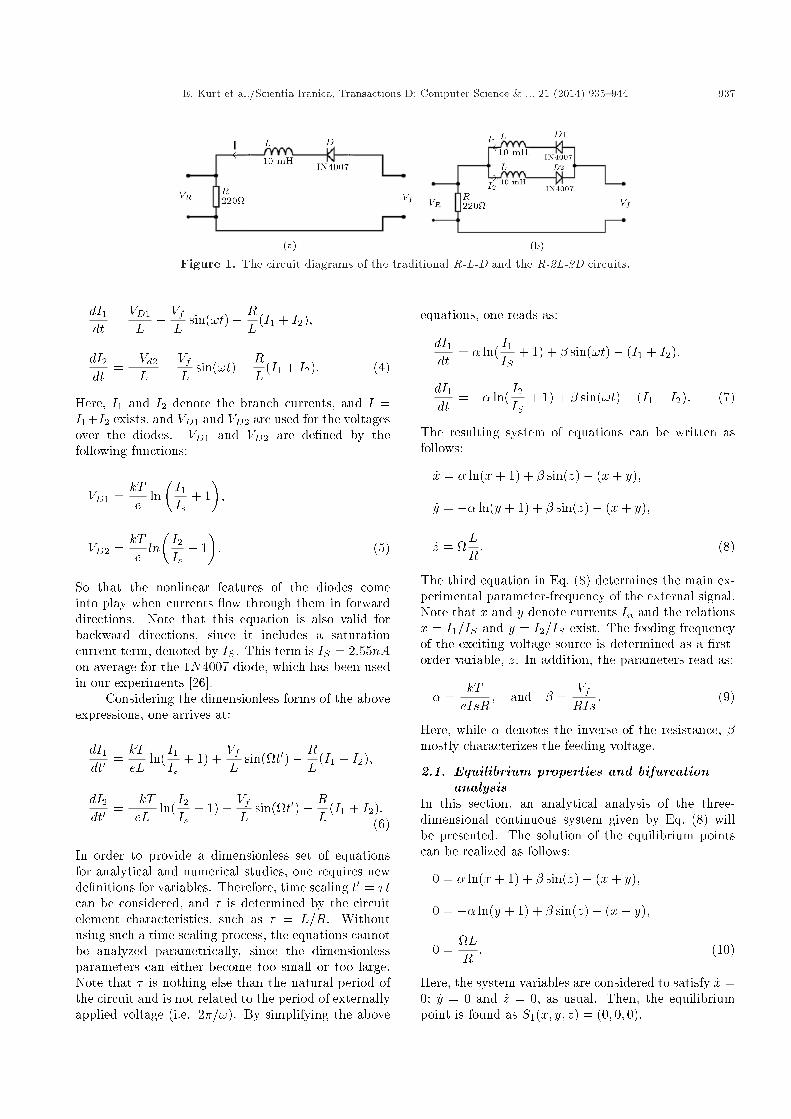
The traditional RLD circuit, which is shown in Fig-ure 1 (a), can be modeled by the following equations:
VD + VL + VR = Vf ;
ID = I0�
exp�eVDkT
�� 1�; (1)
where Vf ; VD; VL and VR are the input voltage, andvoltages across the diode, inductor and resistor, re-spectively. For such a model, period doubling canbe found by measuring the voltage drop across thediode, with respect to the frequency or amplitude ofthe input signal, Vf . While I0 is the saturation currentof the diode, the denominator of the exponentialfunction gives the heat energy at the junction of thediode, which is always accepted as a constant value intheoretical studies. Since the proposed R-2L-2D circuitincludes additional elements, shown in Figure 1(b), theformulation is modi�ed to the following:
VR + VLD = Vf ; (2)
where VLD denotes the voltage across the branchesof the inductor and diode. Note that the diodes areinversely attached to the inductors and parallel to eachother. While current I splits into I1 and I2 on eachdiode branch, di�erent parts of the sinusoidal signalpass through di�erent branches over the entire periodof the input signal. Therefore, one reads as:
VLD = VD1 + LdI1dt; and VLD = VD2 � LdI2dt : (3)
Considering Figure 1 and the equations above, onearrives at:
E. Kurt et al./Scientia Iranica, Transactions D: Computer Science & ... 21 (2014) 935{944 937
Figure 1. The circuit diagrams of the traditional R-L-D and the R-2L-2D circuits.
dI1dt
=VD1
L+VfL
sin(!t)� RL
(I1 + I2);
dI2dt
=�Vd2
L+VfL
sin(!t)� RL
(I1 + I2): (4)
Here, I1 and I2 denote the branch currents, and I =I1+I2 exists, and VD1 and VD2 are used for the voltagesover the diodes. VD1 and VD2 are de�ned by thefollowing functions:
VD1 =kTe
ln�I1Is
+ 1�;
VD2 =kTeln�I2Is
+ 1�: (5)
So that the nonlinear features of the diodes comeinto play when currents ow through them in forwarddirections. Note that this equation is also valid forbackward directions, since it includes a saturationcurrent term, denoted by IS . This term is IS = 2:55nAon average for the 1N4007 diode, which has been usedin our experiments [26].
Considering the dimensionless forms of the aboveexpressions, one arrives at:
dI1dt0 =
kTeL
ln(I1Is
+ 1) +VfL
sin(t0)� RL
(I1 + I2);
dI2dt0 =
�kTeL
ln(I2Is
+ 1) +VfL
sin(t0)� RL
(I1 + I2):(6)
In order to provide a dimensionless set of equationsfor analytical and numerical studies, one requires newde�nitions for variables. Therefore, time scaling t0 = �tcan be considered, and � is determined by the circuitelement characteristics, such as � = L=R. Withoutusing such a time scaling process, the equations cannotbe analyzed parametrically, since the dimensionlessparameters can either become too small or too large.Note that � is nothing else than the natural period ofthe circuit and is not related to the period of externallyapplied voltage (i.e. 2�=!). By simplifying the above
equations, one reads as:
dI1dt
= � ln(I1IS
+ 1) + � sin(!t)� (I1 + I2);
dI1dt
= �� ln(I2IS
+ 1) + � sin(!t)� (I1 + I2): (7)
The resulting system of equations can be written asfollows:
_x = � ln(x+ 1) + � sin(z)� (x+ y);
_y = �� ln(y + 1) + � sin(z)� (x+ y);
_z = LR: (8)
The third equation in Eq. (8) determines the main ex-perimental parameter-frequency of the external signal.Note that x and y denote currents In and the relationsx = I1=IS and y = I2=IS exist. The feeding frequencyof the exciting voltage source is determined as a �rst-order variable, z. In addition, the parameters read as:
� =kTeIsR
; and � =VfRIs
: (9)
Here, while � denotes the inverse of the resistance, �mostly characterizes the feeding voltage.
2.1. Equilibrium properties and bifurcationanalysis
In this section, an analytical analysis of the three-dimensional continuous system given by Eq. (8) willbe presented. The solution of the equilibrium pointscan be realized as follows:
0 = � ln(x+ 1) + � sin(z)� (x+ y);
0 = �� ln(y + 1) + � sin(z)� (x+ y);
0 =LR: (10)
Here, the system variables are considered to satisfy _x =0; _y = 0 and _z = 0, as usual. Then, the equilibriumpoint is found as S1(x; y; z) = (0; 0; 0).
938 E. Kurt et al./Scientia Iranica, Transactions D: Computer Science & ... 21 (2014) 935{944
One can de�ne the Jacobean matrix at S1(0; 0; 0)in the form of:
J =
�������� 1 �1 ��1 ��� 1 �0 0 0
������ : (11)
In order to describe the bifurcation scenario, one hasto de�ne a bifurcation parameter. In our case, � isconsidered the main bifurcation parameter, as in manyprevious studies, since it controls the input voltage ofthe circuit. Eigenvalues � of Eq. (13) can be found asfollows:
J =
�������� 1� � �1 ��1 ��� 1� � �0 0 ��
������ = 0 : (12)
After the calculation of this determinant, one reads as:
�1 = 0;
�2 = �1�p1 + �2;
�3 = �1 +p
1 + �2; (13)
for the eigenvalues. According to these eigenvalue sets,while the �rst two eigenvalues give zero and negativeresults, the third one becomes positive and drives thesystem to chaos, as will be shown in Figure 8 later.Note that the resistor is in � (i.e. 1=R). Thereby,for very high resistances, � will diverge to zero andthe system will then be regular again. In our case,it gives �3 � 45000, which is high enough from zero.Eq. (13) can be obtained as the root of the third orderdeterminant expression from Eq. (12), as follows:
(�� 1� �)f(�+ 1 + �g � � = 0: (14)
In order to carry out the bifurcation analysis onthe equilibrium point S1, we need to �nd out theeigenvectors of Eq. (15). In addition, the bifurcation
parameter, � = 0, should be ascertained. Thus, wearrive at:
(x1; x2; x3) = [0; 0; 1];
(x1; x2; x3) = [��+p
1 + �2; 1; 0];
(x1; x2; x3) = [���p1 + �2; 1; 0]; (15)
for the corresponding eigenvectors. Then, one shouldtransform the Jacobean matrix into its standard form.Using the eigenbasis of Eq. (15), the transformationmatrix is de�ned as follows:0@xy
z
1A=
0@0 ��+p
1+�2 ���p1+�2
0 1 11 0 0
1A0@x1x2x3
1A :(16)
Eq. (9) is transformed into:0BBBBBB@:x1:x2:x3
1CCCCCCA =
��������0 0 00 � 1��+
p1+�2)2
(2p
1+�2)�
(p
1+�2)
0 �(p
1+�2) � (�1+�+p
1+�2)2
(2p
1+�2)
���������0@x1x2x3
1A+
0@g1g2g3
1A ;(17)
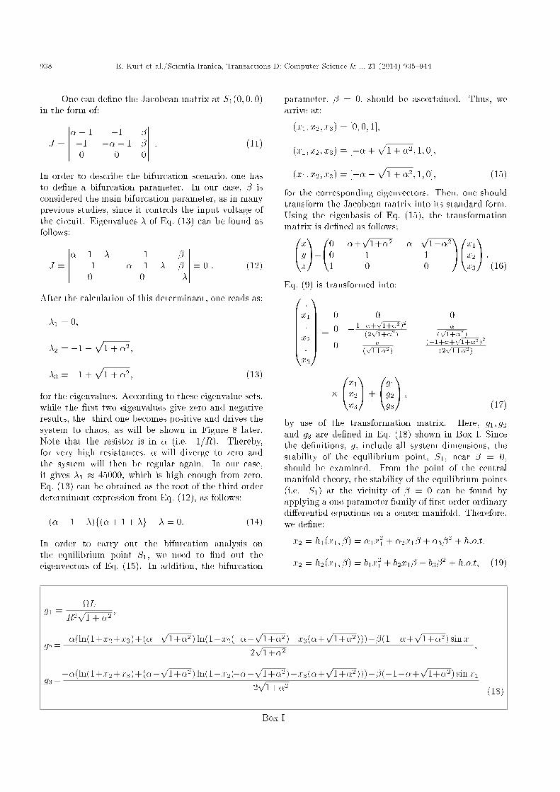
by use of the transformation matrix. Here, g1; g2and g3 are de�ned in Eq. (18) shown in Box I. Sincethe de�nitions, g, include all system dimensions, thestability of the equilibrium point, S1, near � = 0,should be examined. From the point of the centralmanifold theory, the stability of the equilibrium points(i.e. S1) at the vicinity of � = 0 can be found byapplying a one-parameter family of �rst-order ordinarydi�erential equations on a center manifold. Therefore,we de�ne:
x2 = h1(x1; �) = �1x21 + �2x1� + �3�2 + h:o:t;
x2 = h2(x1; �) = b1x21 + b2x1� + b3�2 + h:o:t; (19)
g1 =L
R2p
1 + �2;
g2 =��(ln(1+x2+x3)+(��p1+�2) ln(1+x2(��+
p1+�2)�x3(�+
p1+�2)))+�(1� �+
p1+�2) sinx1
2p
1+�2;
g3 =��(ln(1+x2+x3)+(��p1+�2) ln(1+x2(��+
p1+�2)�x3(�+
p1+�2)))��(�1+�+
p1+�2) sinx1
2p
1+�2:
(18)
Box I

E. Kurt et al./Scientia Iranica, Transactions D: Computer Science & ... 21 (2014) 935{944 939
in order to �nd out the vector �eld on the centermanifold. According to the de�nition of the centermanifold theory, one can �nd out a graph over the x3and � bifurcation parameter, as follows:
Wc(0) = f(x2; x2; x3; �) 2 R4jx1
= h1(x1; �); x2
=h2(x1; �); jx1j <�; j�j< ��; hi(0; 0)=0; i=2; 3g; (20)
for � and �� which are small su�ciently. From the studyof Wiggins [27], such a center manifold must satisfy thestatement:
N(h(x; �)) = Dh0g1 �Bh� g = 0; (21)
where:
h =�h1h2
�; g =
�g2g3
�; and
B =
2664� (1��+p
1+�2)2
(2p
1+�2)�
(p
1+�2)
�(p
1+�2) � (�1+�+p
1+�2)2
(2p
1+�2)
3775 : (22)
Substituting Eqs. (19) into Eq. (21) and using h; g andB in Eq. (22), we get the terms with x1;x2
1; x1�; �2 andrelevant constants from the expression below:2664 :
h1:h2
3775 :g1�2664� (1��+
p1+�2)2
(2p
1+�2)�
(p
1+�2)
�(p
1+�2) � (�1+�+p
1+�2)2
(2p
1+�2)
3775 : �h1h2
�
��g2g3
�= 0 : (23)
Following expressions for the constants from the aboveequation, one gets:
x1 : a1L
Rp
1 + �2= 0;! a1 = 0;
x21 :�
�2p
1 + �2+
(1� �+p
1 + �2)2p
1 + �2
� (��2 + �p
1 + �2)(��+p
1 + �2)2p
1 + �2
�a1
= 0;! a1 = 0;
x1� : �2 :�
(1� �+p
1 + �2)2
2p
1 + �2
� (��2 + �p
1 + �2)(��+p
1 + �2)2p
1 + �2
�2p
1 + �2
�� 1� �+
p1 + �2)
2p
1 + �2= 0;
! a2 =1
1 + �2 +p
1 + �2 � �p1 + �2;
�2 :�
(1� �+p
1 + �2)2
2p
1 + �2+
�2p
1 + �2
� (��2 + �p
1 + �2)(��+p
1 + �2)2p
1 + �2
�� a3 = 0;! a3 = 0:
x1 : b1L
Rp
1 + �2= 0;! b1 = 0
x21 :�
�2p
1 + �2+
(�� 1 +p
1 + �2)2
2p
1 + �2
� (2�3 + 2�2p
1 + �2 + �)2p
1 + �2)
�b1
= 0;! b1 = 0;
x1� : b2 :�
(�� 1 +p
1 + �2)2
2p
1 + �2
� (2�3 + 2�2p
1 + �2 + �)2p
1 + �2)
+�
2p
1 + �2
�� �� 1 +
p1 + �2)
2p
1 + �2= 0;! b2 =
1� ��p1+�2
2(�1+�+�3+p
1+�2��p1+�2+�2(�1+p
1+�2));
�2 :�
(�� 1 +p
1 + �2)2
2p
1 + �2+
�2p
1 + �2
� (2�2 + 2�2p
1 + �2 + �)2p
1 + �2
�b3 = 0;! b3 = 0: (24)
Then, we obtain the de�nitions below for h1; h2 andh3:
940 E. Kurt et al./Scientia Iranica, Transactions D: Computer Science & ... 21 (2014) 935{944
x2 = h1(x1; �) = a2x1� + :::
x3 = h2(x1; �) = b2x1� + ::: (25)
Consequently, if one substitutes the above expressionsinto Eqs. (19) and (17), the vector �eld reduced to thecentre manifold is obtained as follows:
x1 =L
R2p
1 + �2;
_� = 0: (26)
This result proves that the feeding frequency of thecircuit plays an important role in understanding thebifurcation branches for the amplitude of feeding volt-age.
3. Experimental
A schematic diagram of our experimental setup isshown in Figure 1 for the new circuit. For the ordinaryRLD circuit, the setup is easy to apply, as in theliterature. For both circuits, the circuit elementsare de�ned as the resistances, R = 220, and theinductors, L = 10mH. In the case of diodes, thediodes are selected as 1N4007. The circuit is drivenby a BK Precision 4017 function generator givinga sinusoidal feeding with an adjustable frequency, f ,and an amplitude, Vf . For the circuit measurementsand phase space observations, a Kenwood CS-4125oscilloscope has been used.
According to the circuit structure of the proposedcircuit, the diodes operate parallel to each other. Inthat case, while current passes through one of thediodes in one direction, the other diode does not allowthe current. However, the current always ows throughone of the diodes for any frequency range. This realitycauses a �nite voltage on the resistance, R, for theentire period of the circuit. Meanwhile, the perioddoubling mechanism comes into play in two directionswhen suitable frequencies are applied to the circuitinput.
Throughout the study, the parameter space (i.e.the plane of Vf � f) has been explored in order to seethe entire responses of two circuits. At a constantinput voltage, the maximum potential over a diodeis observed when the driving frequency is the sameas the resonant one. During the parameter scan, anumber of period doubling behaviors have also beenobserved as usual for both circuits. While the voltageincrement step is 0:45 V for the RLD circuit, it is0:225 V for the R-2L-2D circuit, in order to get muchclearer results from the latter. In the entire study, thefrequency increment step is adjusted as 10 kHz for lowerfrequency regions and 20 kHz for higher frequencyregions. Thus, the frequency and input voltage ranges
of f = 1 kHz � 560 kHz and Vf = 0V � 3:15V (forRLD circuit), Vf = 0V� 1:575V (for R-2L-2D circuit)have been scanned by the step of �f = 20 Hz and�V = 0:05V, respectively.
4. Results and discussions
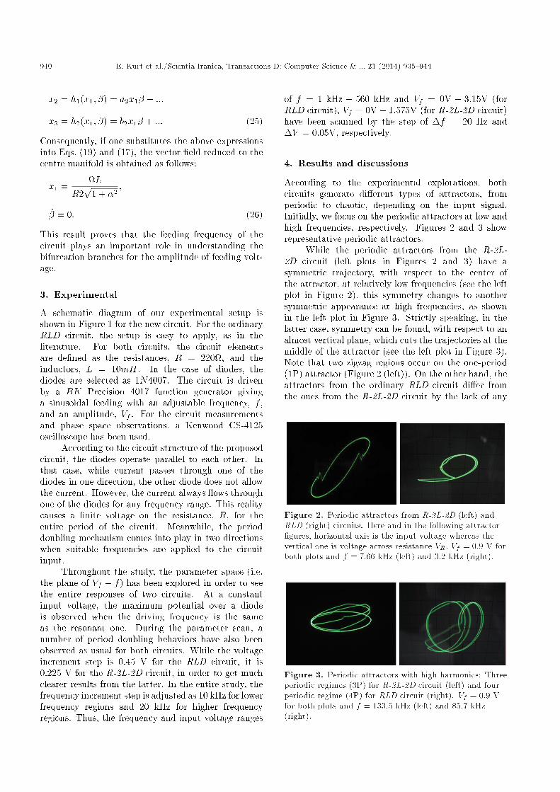
According to the experimental explorations, bothcircuits generate di�erent types of attractors, fromperiodic to chaotic, depending on the input signal.Initially, we focus on the periodic attractors at low andhigh frequencies, respectively. Figures 2 and 3 showrepresentative periodic attractors.
While the periodic attractors from the R-2L-2D circuit (left plots in Figures 2 and 3) have asymmetric trajectory, with respect to the center ofthe attractor, at relatively low frequencies (see the leftplot in Figure 2), this symmetry changes to anothersymmetric appearance at high frequencies, as shownin the left plot in Figure 3. Strictly speaking, in thelatter case, symmetry can be found, with respect to analmost vertical plane, which cuts the trajectories at themiddle of the attractor (see the left plot in Figure 3).Note that two zigzag regions occur on the one-period(1P) attractor (Figure 2 (left)). On the other hand, theattractors from the ordinary RLD circuit di�er fromthe ones from the R-2L-2D circuit by the lack of any
Figure 2. Periodic attractors from R-2L-2D (left) andRLD (right) circuits. Here and in the following attractor�gures, horizontal axis is the input voltage whereas thevertical one is voltage across resistance VR: Vf = 0:9 V forboth plots and f = 7:66 kHz (left) and 3.2 kHz (right).
Figure 3. Periodic attractors with high harmonics: Threeperiodic regimes (3P) for R-2L-2D circuit (left) and fourperiodic regime (4P) for RLD circuit (right). Vf = 0:9 Vfor both plots and f = 133:5 kHz (left) and 85.7 kHz(right).
E. Kurt et al./Scientia Iranica, Transactions D: Computer Science & ... 21 (2014) 935{944 941
symmetric trajectories (see the right plots in Figures 2and 3).
From the literature [13,14], it is known thatthe RLD circuit generates an asymmetric periodicattractor, as in our experiment. However, inversely-directed diodes cause a symmetrical appearance in theattractors from the R-2L-2D circuit. It is obvious thatthe voltage over resistor R takes di�erent values for anyvalues of input voltage.
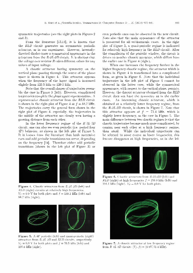
A chaotic attractor having symmetry on thevertical plane passing through the center of the phasespace is shown in Figure 4. This attractor appearswhen the frequency of the input signal is increasedslightly from 133.5 kHz to 139.1 kHz.
Note that the overall shapes of trajectories resem-ble the case in Figure 3 (left). However, complicatedtrajectories complete the phase space representation. Arepresentative chaotic attractor from the RLD circuitis shown in the right plot of Figure 4 at f = 88:7 kHz.The trajectories carry the general form shown in theright plot of Figure 4, especially, the trajectories inthe middle of the attractor are clearly seen having agrowing distance from each other.
In the lower frequency regime of the R-2L-2Dcircuit, one can also see even periodic (i.e. period four4P) behavior, as shown in the left plot of Figure 5.It is known from the literature that both successiveeven and odd periodic transitions can occur, dependingon the frequency [14]. Therefore either odd periodictransitions (shown in the left plot of Figure 3) or
Figure 4. Chaotic attractors from R-2L-2D (left) andRLD (right) circuits at relatively high frequencies.Vf = 0:9 V for both plots and f = 139:1 kHz (left) and88.7 kHz (right).
Figure 5. A 4P periodic (left) and quasi-periodic (right)attractors from R-2L-2D and RLD circuits, respectively.Vf = 0:9 V for both plots and f = 76:5 kHz (left) and107.6 kHz (right).
even periodic ones can be observed in the new circuit.Note also that the main appearance of the attractoris preserved for all subharmonic cases. In the rightplot of Figure 5, a quasi-periodic regime is indicatedfor relatively high frequency in the RLD circuit. Afterthe compilation of the periodic window, the circuit isdriven to another chaotic attractor, which di�ers fromthe earlier one in Figure 4 (right).
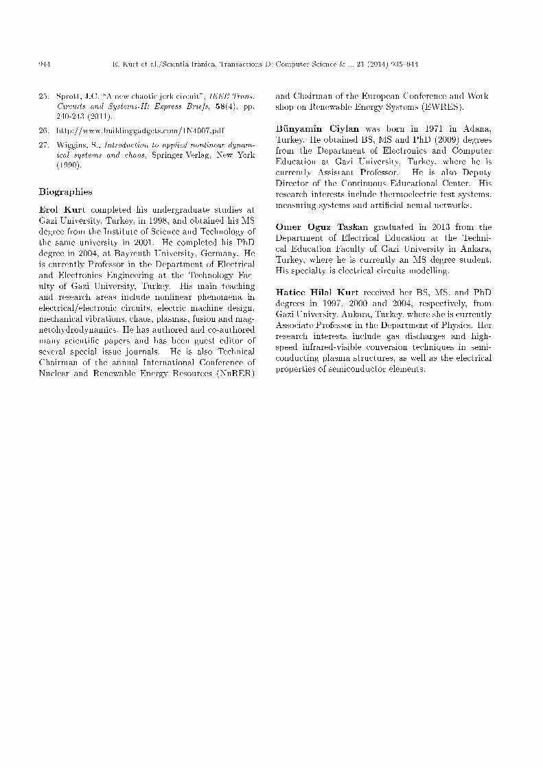
When one increases the frequency further in thehigher frequency chaotic regime, the attractor which isshown in Figure 4 is transformed into a complicatedform, as given in Figure 6. Note that the individualtrajectories in the left plot of Figure 4 cannot beobserved in the latter case, while the symmetricalappearance, with respect to the vertical plane, persists.However, the chaotic attractor obtained from the RLDcircuit does not have the symmetry as in the earliercases. An interesting chaotic attractor, which isobtained at a relatively lower frequency regime, fromthe R-2L-2D circuit, is shown in Figure 7. Note thatthis attractor appears at f = 71:4 kHz, which isslightly lower frequency, as the case in Figure 5. Themain di�erence between two chaotic regimes is that thechaotic trajectories become much more complicated, bycoming near each other at a high frequency regime,than usual. While the individual trajectories canbe selected to some extent at lower frequencies, thisfeature disappears at high frequencies, as in the left
Figure 6. Chaotic attractors from R-2L-2D (left) andRLD (right) at high frequencies f = 158:8 kHz (left) and194.1 kHz (right). Vf = 0:9 V for both plots.
Figure 7. A chaotic attractor at low frequency regimefrom R-2L-2D circuit: (Vf ; f) = (0:9V; 71:4 kHz).
942 E. Kurt et al./Scientia Iranica, Transactions D: Computer Science & ... 21 (2014) 935{944
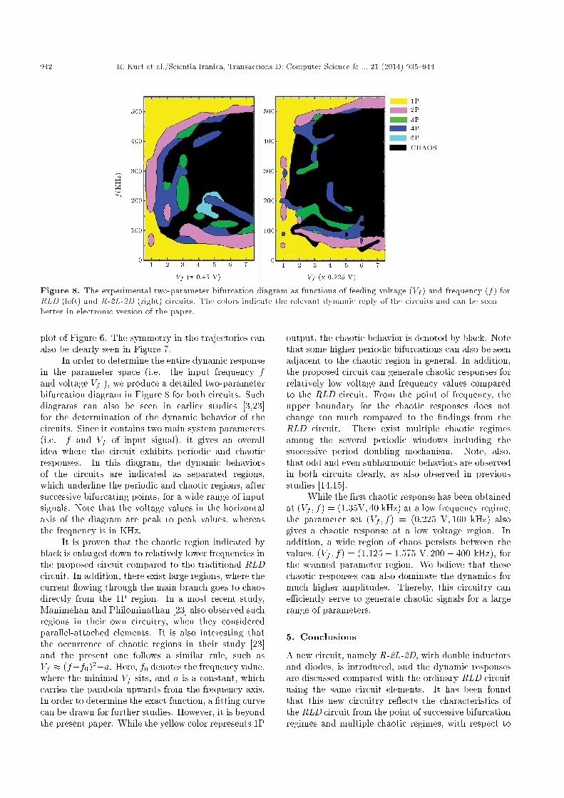
Figure 8. The experimental two-parameter bifurcation diagram as functions of feeding voltage (Vf ) and frequency (f) forRLD (left) and R-2L-2D (right) circuits. The colors indicate the relevant dynamic reply of the circuits and can be seenbetter in electronic version of the paper.
plot of Figure 6. The symmetry in the trajectories canalso be clearly seen in Figure 7.
In order to determine the entire dynamic responsein the parameter space (i.e. the input frequency fand voltage Vf ), we produce a detailed two-parameterbifurcation diagram in Figure 8 for both circuits. Suchdiagrams can also be seen in earlier studies [3,23]for the determination of the dynamic behavior of thecircuits. Since it contains two main system parameters(i.e. f and Vf of input signal), it gives an overallidea where the circuit exhibits periodic and chaoticresponses. In this diagram, the dynamic behaviorsof the circuits are indicated as separated regions,which underline the periodic and chaotic regions, aftersuccessive bifurcating points, for a wide range of inputsignals. Note that the voltage values in the horizontalaxis of the diagram are peak to peak values, whereasthe frequency is in KHz.
It is proven that the chaotic region indicated byblack is enlarged down to relatively lower frequencies inthe proposed circuit compared to the traditional RLDcircuit. In addition, there exist large regions, where thecurrent owing through the main branch goes to chaosdirectly from the 1P region. In a most recent study,Manimehan and Philominathan [23] also observed suchregions in their own circuitry, when they consideredparallel-attached elements. It is also interesting thatthe occurrence of chaotic regions in their study [23]and the present one follows a similar rule, such asVf � (f�f0)2+a. Here, f0 denotes the frequency value,where the minimal Vf sits, and a is a constant, whichcarries the parabola upwards from the frequency axis.In order to determine the exact function, a �tting curvecan be drawn for further studies. However, it is beyondthe present paper. While the yellow color represents 1P
output, the chaotic behavior is denoted by black. Notethat some higher periodic bifurcations can also be seenadjacent to the chaotic region in general. In addition,the proposed circuit can generate chaotic responses forrelatively low voltage and frequency values comparedto the RLD circuit. From the point of frequency, theupper boundary for the chaotic responses does notchange too much compared to the �ndings from theRLD circuit. There exist multiple chaotic regimesamong the several periodic windows including thesuccessive period doubling mechanism. Note, also,that odd and even subharmonic behaviors are observedin both circuits clearly, as also observed in previousstudies [14,15].
While the �rst chaotic response has been obtainedat (Vf ; f) = (1:35V; 40 kHz) at a low frequency regime,the parameter set (Vf ; f) = (0:225 V; 160 kHz) alsogives a chaotic response at a low voltage region. Inaddition, a wide region of chaos persists between thevalues, (Vf ; f) = (1:125� 1:575 V; 200� 400 kHz), forthe scanned parameter region. We believe that thesechaotic responses can also dominate the dynamics formuch higher amplitudes. Thereby, this circuitry cane�ciently serve to generate chaotic signals for a largerange of parameters.
5. Conclusions
A new circuit, namely R-2L-2D, with double inductorsand diodes, is introduced, and the dynamic responsesare discussed compared with the ordinary RLD circuitusing the same circuit elements. It has been foundthat this new circuitry re ects the characteristics ofthe RLD circuit from the point of successive bifurcationregimes and multiple chaotic regimes, with respect to

E. Kurt et al./Scientia Iranica, Transactions D: Computer Science & ... 21 (2014) 935{944 943
the input voltage and frequency. This study is novelin the sense that the literature does not contain anyinformation in regard to the proposed circuit with theforward and reverse directed connection of the diodes.This kind of connection yields to many symmetricalattractors. In addition, the proposed circuit exhibits awider chaotic region compared to the traditional R-L-D circuit. Strictly speaking, the attractors observed inthe R-2L-2D circuit have certain symmetries, accordingto either the center of the attractor or the verticalplane passing through the center of the phase spaceapart from the ordinary RLD circuit. In addition,the trajectories become much complicated for highfrequency inputs for both circuits. It can be alsoconcluded that the chaotic region enlarges toward thelower frequencies in the proposed circuit, whereas thedynamics resemble ordinary RLD circuits at higherfrequencies. In addition, new circuitry can generatethe chaotic dynamics at lower voltages compared tothe RLD circuit. Therefore we expect that this newcircuit can easily serve the fundamental theory of chaosand bifurcation, since the dependence on the excitationfrequency determines the bifurcation scenario for a con-stant excitation voltage. Due to its simple circuitry, theproposed circuit can also be used for the educationalpurposes of engineers and physicists in the labs.
References
1. Kurt, E. and Cant�urk, M. \Bifurcations and hy-perchaos from a dc driven non-identical Josephsonjunction system", Int. J. Bif. Chaos, 20(11), pp. 3725-3740 (2010).
2. Kurt, E. and Cant�urk, M. \Chaotic dynamics of resis-tively coupled DC-driven distinct Josephson junctionsand the e�ects of circuit parameters", Physica D: Nonl.Phen., 238(22), pp. 2229-2237 (2009).
3. Kurt, E. \Nonlinearities a non-autonomous chaoticcircuit with a non-autonomous model of Chuas diode",Phys. Scr., 74, pp. 22-27 (2006).
4. Kurt, E., Ozturk, M.K. and Kasap, R. \Investigatingthe most appropriate parameters of the nonlinearresistor circuit time series", J. Inst. Sci. & Tech. GaziUni., 14(4), pp. 1261-1269 (2001).
5. Thompson, J.M.T. and Bishop, S.R., Nonlinearity andChaos in Engineering Dynamics, John Wiley and Sons,England (1994).
6. Kennedy, M.P., Rovatti, R. and Setti, G. (edited byRaton, B.), Chaotic Electronics in Telecommunica-tions, CRC Press, FL (2000).
7. Uchida, A., Davis, P. and Itaya, S. \Generationof information theoretic secure keys using a chaoticsemiconductor laser", Appl. Phys. Lett., 83(15), pp.3213-3215 (2003).
8. Van Wiggeren, G.D. and Roy, R. \Communicationwith chaotic lasers", Science, 279, pp. 1198-1200(1998).
9. Dana, S.K., Sengupta, D. and Edoh, K. \Chaotic dy-namics in Josephson junction", IEEE Trans. CircuitsSystems I: Fund. Theory and Appl., 48(8), pp. 990-996(2001).
10. Kapitaniak, T., Controlling Chaos, Academic Press,San Diego (1996).
11. Stojanovski, T., Pihl, J. and Kocarev, L. \Chaosbased random number generators - Part II: Practicalrealization", IEEE Trans. Circ. Syst.-I: Fund. Theo.Appl., 48, pp. 382-385 (2001).
12. Tsubone, T. and Saito, T. \Hyperchaos from a 4-Dmanifold piecewise-linear system," IEEE Trans. Cir.Syst.-I: Fund. Theo. Appl., 45, pp. 889-894 (1998).
13. Linsay, P.S. \Period doubling and chaotic behaviour ina driven anharmonic oscillator", Phys. Rev. Lett., 47,pp. 1349-1352 (1981).
14. Testa, J., Perez, J. and Je�ries, C. \Evidence foruniversal chaotic behaviour of a driven oscillator",Phys. Rev. Lett., 48, pp. 714-717 (1982).
15. Azzouz, A., Duhr, R. and Hasler, M. \Transitionto chaos in a simple nonlinear circuit driven by asinusoidal voltage source", IEEE Trans. Circuits Syst.,CAS-30 (1983).
16. Su, Z., Rollings, R.W. and Hunt, E.R. \Universalproperties at the onset of chaos in diode resonatorsystems", Phys. Rev. A, 40(5), pp. 2689-2697 (1989).
17. Van Buskirk, R. and Je�ries, C. \Observation ofchaotic dynamics of coupled nonlinear oscillators",Phys. Rev. A, 31, pp. 3332-3357 (1985).
18. Huang, J.Y. and Kim, J.J. \Type-II intermittency ina coupled nonlinear oscillator: Experimental observa-tion", Phys. Rev. A, 36(3), pp. 1495-1497 (1987).
19. Kim, Y.H. and Kim, J.J. \Observation of quasiperiod-icity in a single diode circuit", J. Korean Phys. Soc.,27(2), pp. 225-227 (1994).
20. Kasap, R. and Kurt, E. \Investigation of chaos inthe RL-diode circuit by using the BDS test", J. Appl.Math. Decision Sci., 2(2), pp. 193-199 (1998).
21. Kurt, E., Acar, S. and Kasap, R. \A comparison ofchaotic circuits from a statistical approach", Math.Comp. App. J, 5(2), pp.95-103 (2000).
22. Inaba, N., Nishio, Y. and Endo, T. \Chaos viatorus breakdown from a four-dimensional autonomousoscillator with two diodes", Physica D, 240(11), pp.903-912 (2011).
23. Manimehan, I. and Philominathan, P. \Compositedynamical behaviors in a simple series{parallel LCcircuit", Chaos, Solitons and Fractals, 45(12), pp.1501-1509 (2012).
24. Munmuangsaen, B., Srisuchinwong, B. and Sprott,J.C. \Generalization of the simplest autonomouschaotic system", Physics Letters A, 375, pp. 1445-1450(2011).
944 E. Kurt et al./Scientia Iranica, Transactions D: Computer Science & ... 21 (2014) 935{944
25. Sprott, J.C. \A new chaotic jerk circuit", IEEE Trans.Circuits and Systems-II: Express Briefs, 58(4), pp.240-243 (2011).
26. http://www.buildinggadgets.com/1N4007.pdf
27. Wiggins, S., Introduction to applied nonlinear dynam-ical systems and chaos, Springer-Verlag, New York(1990).
Biographies
Erol Kurt completed his undergraduate studies atGazi University, Turkey, in 1998, and obtained his MSdegree from the Institute of Science and Technology ofthe same university in 2001. He completed his PhDdegree in 2004, at Bayreuth University, Germany. Heis currently Professor in the Department of Electricaland Electronics Engineering at the Technology Fac-ulty of Gazi University, Turkey. His main teachingand research areas include nonlinear phenomena inelectrical/electronic circuits, electric machine design,mechanical vibrations, chaos, plasmas, fusion and mag-netohydrodynamics. He has authored and co-authoredmany scienti�c papers and has been guest editor ofseveral special issue journals. He is also TechnicalChairman of the annual International Conference ofNuclear and Renewable Energy Resources (NuRER)
and Chairman of the European Conference and Work-shop on Renewable Energy Systems (EWRES).
B�unyamin Ciylan was born in 1971 in Adana,Turkey. He obtained BS, MS and PhD (2009) degreesfrom the Department of Electronics and ComputerEducation at Gazi University, Turkey, where he iscurrently Assistant Professor. He is also DeputyDirector of the Continuous Educational Center. Hisresearch interests include thermoelectric test systems,measuring systems and arti�cial neural networks.
Omer Oguz Taskan graduated in 2013 from theDepartment of Electrical Education at the Techni-cal Education Faculty of Gazi University in Ankara,Turkey, where he is currently an MS degree student.His specialty is electrical circuits modelling.
Hatice Hilal Kurt received her BS, MS, and PhDdegrees in 1997, 2000 and 2004, respectively, fromGazi University, Ankara, Turkey, where she is currentlyAssociate Professor in the Department of Physics. Herresearch interests include gas discharges and high-speed infrared-visible conversion techniques in semi-conducting plasma structures, as well as the electricalproperties of semiconductor elements.