biennial scientifi c report 2013— - triumf
TRANSCRIPT

BiennialScientifi cReport2013—2015
Copyright © 2016 TRIUMF
Biennial Science Report 2013–2015
All rights reserved
Editor-in-chief: Marcello Pavan
Scientifi c Editors: Greg Hackman, Reiner Kruecken, David Morrissey, Colin Morton
TRIUMF Editors: Melissa Baluk, Byron Jennings, Carla Rodrigo
Copy Editor/Proof Reader: Melva McLean
TRIUMF’s activities are supported through a combination of public funds, revenues generated from commercial
activities, and small contributions generated from commercial activities, and small contributions received through
scholarships, awards, and personal donations. We gratefully wish to acknowledge the following sources of
public support (in alphabetical order): Canada Foundation for Innovation, Canadian Institutes of Health Research,
Genome BC, National Research Council Canada, Natural Resources Canada, Natural Sciences and Engineering
Research Council, Province of British Columbia, Province of Manitoba, Province of Ontario, Province of Nova
Scotia, and Western Economic Diversifi cation Canada.
For additional copies of this report or for more information, please contact:
Strategic Communications Offi ce, TRIUMF
4004 Wesbrook Mall, Vancouver, BC V6T 2A3, Canada
Telephone: 604-222 1047
E-mail: [email protected]
Website: www.triumf.ca
Design and Layout: BurnKit, Inc., Vancouver
Biennial Scientifi c Report 2013—2015

4ARIEL – ADVANCED RARE-ISOTOPE LABORATORY
104
Biennial Scientifi c Report 2013—2015
4ARIEL – ADVANCED RARE-ISOTOPE LABORATORY
4.1 — Introduction and Science Motivation
4.2 — ARIEL Civil Constrcuction
4.3 — Accelerators and Beam Lines
4.3. 1 — Introduction
4.3.2 — E-Hall Rehabilitation
4.3.3 — Accelerators and Beam Lines
2.3.4 — Electron Gun
4.3.5 — (VECC) Injector Test Stand
4.3.6 — Cryomodules Design
4.3. 7 — SRF Cavity Resonators
4.3.8 — Injector Cryomodule
4.3.9 — Accelerator Cryomodule
4.3.10 — 4K/2K Inserts
4.3.11 — Radio-Frequency Equipment
4.3.12 — Cryogenic Equipment
4.3.13 — Electrical Infrastructure
4.3.14 — Beam Lines
4.3.15 — Beam Line Design and Installation
4.3.16 — Beam Diagnostic Equipment
4.3.17 — Vacuum Equipment
4.3.18 — e-linac Beam Demonstration
4.1 Introduction and Science Motivation 105
Biennial Scientifi c Report 2013�—2015 Chapter 4
4.1 INTRODUCTION AND SCIENCE MOTIVATION
In September 2014, TRIUMF completed the fi rst stage
of the construction of the Advanced Rare Isotope
Laboratory (ARIEL), with the goal to signifi cantly expand
TRIUMF’s Rare Isotope Beam (RIB) program for Nuclear
Physics and Astrophysics, Nuclear Medicine, and
Molecular and Materials Science.
Rare isotopes are powerful tools for scientifi c discov-
ery, such as determining the structure and dynamics of
atomic nuclei, understanding the processes by which
heavy elements in the Universe were created, and
enabling precision tests of fundamental symmetries that
may challenge the Standard Model of particle physics.
Rare isotopes or “radioisotopes” are also foundational
for modern medical imaging techniques like PET and
SPECT, and useful for therapeutic purposes, such as
the treatment of cancer tumours. They can also serve
as unique probes to characterize magnetic and elec-
tronic properties at surfaces and interfaces between
materials.
At its heart, the full ARIEL project consists of a 500 kW,
50 MeV electron accelerator for isotope production via
photo-production and photo-fi ssion as well as a second
proton beam line from TRIUMF’s 500 MeV cyclotron for
isotope production via proton-induced spallation and
fi ssion.
The ARIEL scientifi c program will be implemented
in stages beginning with 8Li photo-production for
materials science. This stage will be followed by the
implementation of the production of neutron-rich
fi ssion fragments through photo-fi ssion of uranium with
more than 1013 fi ssions per second in the fi nal imple-
mentation. Photo-fi ssion will enable the study of the
very neutron-rich nuclei involved in the astrophysical
r-process responsible for the production of the heavy
elements from iron to uranium in supernova explosions
or the merger of neutron stars. The new proton beam
line (BL4N) will deliver up to 100 microAmp beam onto
an additional production target. In conjunction with
the e-linac production target TRIUMF will go from the
current single ISAC RIB production target to the parallel
production of RIBs on three target stations. This new
and unique multi-user capability will allow for a much
better exploitation of the available forefront experimen-
tal facilities at ISAC. Aside from the tremendous gain in
available time for the materials science program, other
experimental programs that need large amounts of
beam time will be enabled by the multi-user capability
of ARIEL. In addition, capabilities for the harvesting of
medical elements will be implemented.
This fi rst stage of the ARIEL project, which was funded
through the Canada Foundation for Innovation and
the BC Knowledge and Development Fund and spear-
headed by the University of Victoria, comprised the
civil construction for the full ARIEL project as well as
the development of the new superconducting electron
accelerator (e-linac) (see Figure 1).
The subsequent sections will describe the comple-
tion of the ARIEL building as well as details on the
e-linac accelerator development, construction, and
commissioning.
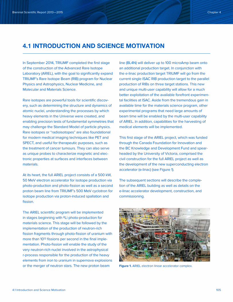
Figure 1. ARIEL electron linear accelerator complex.

4.1 Introduction and Science Motivation 106
Biennial Scientifi c Report 2013�—2015 Chapter 4
4.2 ARIEL CIVIL CONSTRUCTION
R. DAWSON
In June 2010, the Province of British Columbia
provided the University of Victoria with $30.7M
through the British Columbia Knowledge
Development Fund for ARIEL civil construction at
TRIUMF. Chernoff -Thompson Architects led the
overall architecture and engineering contract, which
was awarded in October 2010. The schematic design
report was received on March 4, 2011, and the design
development report was received on July 4, 2011.
The construction plan consisted of four main
components: the demolition of the old Stores build-
ing and excavation of the ARIEL building sited;
construction of the new Stores building; construc-
tion of the new Badge room; and construction of the
ARIEL infrastructure, including the main building,
the new Helium Compressor Building, and major
renovations to transform the former Proton Hall to
the new Electron Hall (see Figure 2).
The demolition and excavation contract was awarded
and work started on October 17, 2011 and was substan-
tially completed by April 2012. The completion target
date of January 20, 2012 was delayed due to unfore-
seen ground water and soil conditions as well as a
water main failure. Construction for the new Stores
building and Badge room were completed in 2011.
Work on the new Stores building started March 28,
2011 and occupancy was achieved on schedule on
September 23, 2011. Construction on the new Badge
room started August 3, 2011 and was completed
slightly behind scheduled completion on December
10, 2011, primarily because of equipment delivery and
coordination logistics (see Figures 3 and 4).
Figure 2. Electron linac hall during rehabilitation Figure 3. Helium compressor building and storage tank

4.1 Introduction and Science Motivation 107
Biennial Scientifi c Report 2013—2015 Chapter 4
The construction tender for construction of ARIEL was
issued December 14, 2011 and awarded February 9,
2012. The ARIEL main construction contract included
work in the Electron Hall, the Helium Compressor
Building, and ARIEL building. Both the Electron Hall
and the Helium Compressor Building were completed
in late 2012. The ARIEL building was substantially
completed on September 25, 2013.
In April 2013, the work of engineering consultants
Stantee Consulting Ltd. (mechanical), Applied
Engineering Solutions Ltd. (electrical), and Bush,
Bohman & Partners Ltd. (structural) was recognized
with the 2013 Engineering Excellence Award of
Merit by the Association of Consulting Engineering
Companies of British Columbia. In October 24, at the
Vancouver Regional Construction Association’s 26th
annual Awards of Excellence gala, Ellis Don Corp took
home the general contractor award for $15 million to
$55 million projects for its work as primary contractor
for the ARIEL building project.
Figure 4. New Stores building

4.3 Accelerators and Beam Lines 108
Biennial Scientifi c Report 2013�—2015 Chapter 4
4.3 ACCELERATORS AND BEAM LINES
S. KOSCIELNIAK
4.3.1 Introduction
On September 30, 2014, the Advanced Rare IsotopE
Laboratory project (ARIEL-I) was complete, and a 23
MeV electron beam was delivered to the EABD beam
stop. The second phase, ARIEL-II, will add target
stations, mass separators and RIB beam Lines to
deliver rare isotopes to the existing ISAC-II experi-
mental facility. The e-linac science infrastructure
and all components were funded by the Canadian
Foundation for Innovation (CFI). As a contributing
development, the electron gun and low-energy beam
test stand were prototyped in the ISAC-II building
under a collaboration with Variable Energy Cyclotron
(VECC) of Kolkata, India.
Gamma-ray induced fi ssion, using copious photons produced from a primary electron beam, is an invented-in-Canada mechanism for RIB production
that is complementary to proton-induced spall-
ation, with the advantages of niche neutron-rich
species and lower isobaric contamination. An order
of magnitude higher RIB production requires a 50
MeV, 10 mA electron driver beam. Electron beams
are easy to produce and are relativistic above 1
MeV, which confers the advantage of compact,
constant frequency accelerating structures. L-band
(≈ 1GHz) SRF technology has been pursued by the
high-energy physics community as an enabling
technology for a TeV-scale linear collider since the
1980s and is now considered “mature” for transfer to
industry. Effi cient operation of these cavities requires
immersion in a 2K bath of liquid helium. Niobium SRF
cavities have advantages over normal-conducting
copper cavities of continuous rather than pulsed
operation and much reduced operating costs. The
e-linac provides an opportunity for TRIUMF to master
this SRF technology and transfer the fabrication
know-how to the local Richmond-based company
PAVAC Industries Inc.
4.3.2 E-Hall Rehabilitation
The former proton hall was emptied of obsolete
science equipment in 2012. Subsequently, the
space was taken over by Ellis Don for the pouring of
concrete: very massive shielding for BL4N to north,
and massive shielding to south to support ERL opera-
tion (see Figure 2, p. 108) Occupancy of the e-hall
was taken in February 2013 and equipment installa-
tions began at that time, starting with the LHe dewar
and ALAT cold box.
4.3.3 Accelerators and Beam Lines
The mast head achievements from 2012–14 were:
(i) development of two niobium 9-cell elliptical-type
cavities both meeting the design specifi cation of bare
quality factor Q=10^10 at an accelerating gradient of 10
MV/m; (ii) acceptance testing of two 1.3 GHz c.w. klys-
trons to 270 kW each; (iii) acceptance testing of the 4K
cryogenic plant beyond the design specifi cation 800 W
cooling power at 4.6K and maximum liquefaction rate
of 380 l/h; (iv) construction of the e-linac beamlines;
(v) integration of all e-linac systems; and (vi) delivery of
the 23 MeV electron beam. Progress that led to these
achievements is detailed below.
4.3 Accelerators and Beam Lines 109
Biennial Scientifi c Report 2013—2015 Chapter 4
4.3.4 Electron Gun
The electron gun (e-gun) provides up to 10 mA of 300
keV kinetic energy electron beam. The main components
are an in-air HV power supply, the gridded thermionic
gun electrically isolated in an SF6 fi lled vessel, and an
RF modulation feedthrough. Unique features of the gun
are its inverted cathode/anode geometry to reduce dark
current, and transmission of the RF modulation through a
dielectric (ceramic) waveguide.
The gun interfaces to the waveguide through a shroud
and corona domes inside the SF6 tank. The gun cath-
ode, anode and ceramic stand-off were assembled
May, 2013. The waveguide, shroud and corona domes
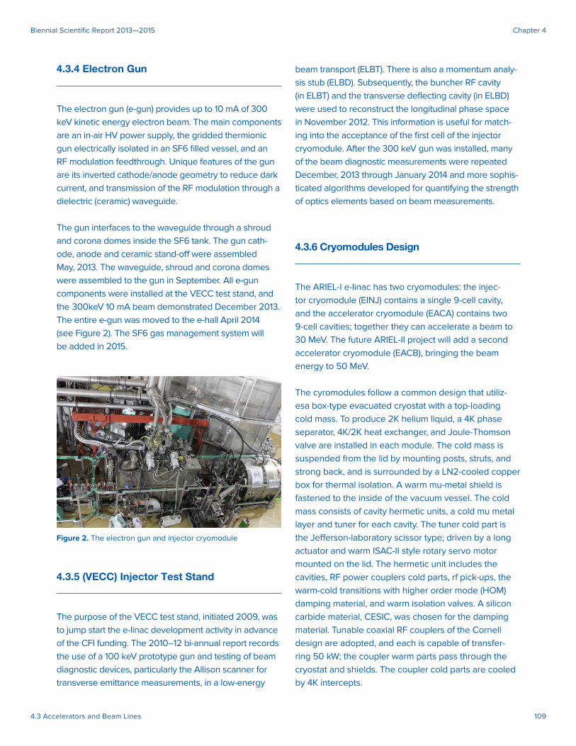
were assembled to the gun in September. All e-gun
components were installed at the VECC test stand, and
the 300keV 10 mA beam demonstrated December 2013.
The entire e-gun was moved to the e-hall April 2014
(see Figure 2). The SF6 gas management system will
be added in 2015.
4.3.5 (VECC) Injector Test Stand
The purpose of the VECC test stand, initiated 2009, was
to jump start the e-linac development activity in advance
of the CFI funding. The 2010–12 bi-annual report records
the use of a 100 keV prototype gun and testing of beam
diagnostic devices, particularly the Allison scanner for
transverse emittance measurements, in a low-energy
beam transport (ELBT). There is also a momentum analy-
sis stub (ELBD). Subsequently, the buncher RF cavity
(in ELBT) and the transverse defl ecting cavity (in ELBD)
were used to reconstruct the longitudinal phase space
in November 2012. This information is useful for match-
ing into the acceptance of the fi rst cell of the injector
cryomodule. After the 300 keV gun was installed, many
of the beam diagnostic measurements were repeated
December, 2013 through January 2014 and more sophis-
ticated algorithms developed for quantifying the strength
of optics elements based on beam measurements.
4.3.6 Cryomodules Design
The ARIEL-I e-linac has two cryomodules: the injec-
tor cryomodule (EINJ) contains a single 9-cell cavity,
and the accelerator cryomodule (EACA) contains two
9-cell cavities; together they can accelerate a beam to
30 MeV. The future ARIEL-II project will add a second
accelerator cryomodule (EACB), bringing the beam
energy to 50 MeV.
The cyromodules follow a common design that utiliz-
esa box-type evacuated cryostat with a top-loading
cold mass. To produce 2K helium liquid, a 4K phase
separator, 4K/2K heat exchanger, and Joule-Thomson
valve are installed in each module. The cold mass is
suspended from the lid by mounting posts, struts, and
strong back, and is surrounded by a LN2-cooled copper
box for thermal isolation. A warm mu-metal shield is
fastened to the inside of the vacuum vessel. The cold
mass consists of cavity hermetic units, a cold mu metal
layer and tuner for each cavity. The tuner cold part is
the Jeff erson-laboratory scissor type; driven by a long
actuator and warm ISAC-II style rotary servo motor
mounted on the lid. The hermetic unit includes the
cavities, RF power couplers cold parts, rf pick-ups, the
warm-cold transitions with higher order mode (HOM)
damping material, and warm isolation valves. A silicon
carbide material, CESIC, was chosen for the damping
material. Tunable coaxial RF couplers of the Cornell
design are adopted, and each is capable of transfer-
ring 50 kW; the coupler warm parts pass through the
cryostat and shields. The coupler cold parts are cooled
by 4K intercepts.
Figure 2. The electron gun and injector cryomodule
4.3 Accelerators and Beam Lines 110
Biennial Scientifi c Report 2013—2015 Chapter 4
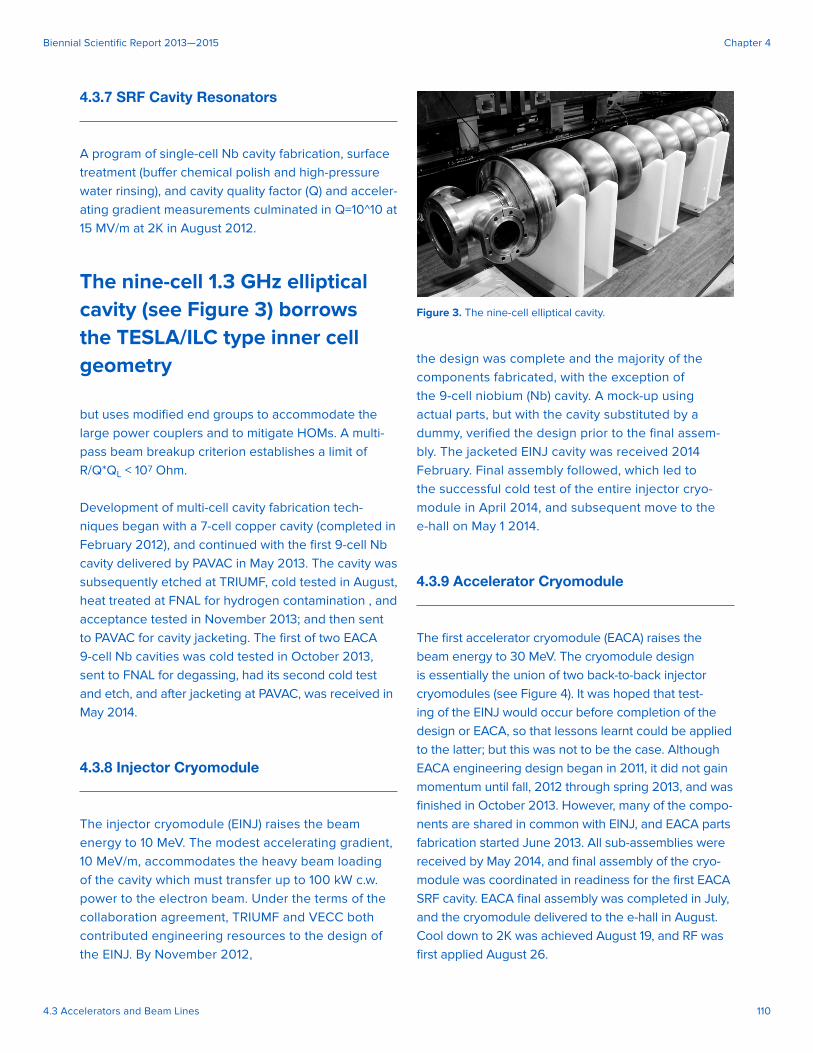
4.3.7 SRF Cavity Resonators
A program of single-cell Nb cavity fabrication, surface
treatment (buff er chemical polish and high-pressure
water rinsing), and cavity quality factor (Q) and acceler-
ating gradient measurements culminated in Q=10^10 at
15 MV/m at 2K in August 2012.
The nine-cell 1.3 GHz elliptical cavity (see Figure 3) borrows the TESLA/ILC type inner cell geometry
but uses modifi ed end groups to accommodate the
large power couplers and to mitigate HOMs. A multi-
pass beam breakup criterion establishes a limit of
R/Q*QL < 107 Ohm.
Development of multi-cell cavity fabrication tech-
niques began with a 7-cell copper cavity (completed in
February 2012), and continued with the fi rst 9-cell Nb
cavity delivered by PAVAC in May 2013. The cavity was
subsequently etched at TRIUMF, cold tested in August,
heat treated at FNAL for hydrogen contamination , and
acceptance tested in November 2013; and then sent
to PAVAC for cavity jacketing. The fi rst of two EACA
9-cell Nb cavities was cold tested in October 2013,
sent to FNAL for degassing, had its second cold test
and etch, and after jacketing at PAVAC, was received in
May 2014.
4.3.8 Injector Cryomodule
The injector cryomodule (EINJ) raises the beam
energy to 10 MeV. The modest accelerating gradient,
10 MeV/m, accommodates the heavy beam loading
of the cavity which must transfer up to 100 kW c.w.
power to the electron beam. Under the terms of the
collaboration agreement, TRIUMF and VECC both
contributed engineering resources to the design of
the EINJ. By November 2012,
the design was complete and the majority of the
components fabricated, with the exception of
the 9-cell niobium (Nb) cavity. A mock-up using
actual parts, but with the cavity substituted by a
dummy, verifi ed the design prior to the fi nal assem-
bly. The jacketed EINJ cavity was received 2014
February. Final assembly followed, which led to
the successful cold test of the entire injector cryo-
module in April 2014, and subsequent move to the
e-hall on May 1 2014.
4.3.9 Accelerator Cryomodule
The fi rst accelerator cryomodule (EACA) raises the
beam energy to 30 MeV. The cryomodule design
is essentially the union of two back-to-back injector
cryomodules (see Figure 4). It was hoped that test-
ing of the EINJ would occur before completion of the
design or EACA, so that lessons learnt could be applied
to the latter; but this was not to be the case. Although
EACA engineering design began in 2011, it did not gain
momentum until fall, 2012 through spring 2013, and was
fi nished in October 2013. However, many of the compo-
nents are shared in common with EINJ, and EACA parts
fabrication started June 2013. All sub-assemblies were
received by May 2014, and fi nal assembly of the cryo-
module was coordinated in readiness for the fi rst EACA
SRF cavity. EACA fi nal assembly was completed in July,
and the cryomodule delivered to the e-hall in August.
Cool down to 2K was achieved August 19, and RF was
fi rst applied August 26.
Figure 3. The nine-cell elliptical cavity.

4.3 Accelerators and Beam Lines 111
Biennial Scientifi c Report 2013—2015 Chapter 4
4.3.10 4K/2K Inserts
Whereas the ISAC-II quarter wave cavities, operating
at 140 MHz, need a 4K LHe bath, the e-linac elliptical
cavities, operating at order 1300 MHz, need a 2K LHe
bath to reduce the otherwise higher BCS RF power
loss in the superconducting metal.
There is a 4K/2K insert on board each cryomodule,
whose main purpose is to generate 2K liquid entering
the cavities from 4K liquid entering the cryomodule.
2K liquid is produced by passing 4 liquid through
a heat exchanger in counter fl ow with the return-
ing exhaust gas from the 2K phase separator, and
then expanding the gas to 30 mbar through a Joule-
Thomson expansion valve. The header pipe above the
cavity string acts as a 2K phase separator, and delivers
cold gas back through the 4K/2K heat exchanger to
the SA pumping system as a liquid load.
Further, a 4K LHe reservoir in each cryomodules acts
as a 4K phase separator. Cold gas is returned to a
common return trunk and then delivered back to
the cold box where it represents a refrigerator load.
A siphon circuit from the 4K reservoir cools the 4K
intercepts, with vapour returning back to the reservoir.
Initial cool down of the cold mass is done by delivering
4K liquid from the 4K phase separator to the bottom of
the cold mass through a dedicated cool down valve.
The prototype 4K/2K insert underwent preliminary
testing at 77K & 4K October to November, and was
found to be satisfactory May 2013, after modifi ca-
tion of the 4K syphon to reduce convection in the 4K
reservoir.
4.3.11 Radio-Frequency Equipment
The purpose of the RF equipment is to energize the
cavity resonators with travelling wave electrical fi elds
that accelerate the electrons. When superconduct-
ing cavities are used, almost 100% of the incident RF
power is transferred to the particle beam.
The 2010–12 bi-annual report records the use of a
30kW Inductive Output Tube (IOT) as the basis for the
RF coupler conditioning station. Two couplers at a
time are tested/conditioned under either travelling or
standing wave conditions ranging from 10 to 40 kW
peak power.
The time frame covered by the 2012–14 report
concerns the 1.3 GHz high-power RF system that
supplies up to 100kW to each of the three SRF cavi-
ties. The basic layout is that an RF source (klystron)
delivers power via a circulator and waveguide distri-
bution system to the two coaxial input couplers that
feed a single SRF cavity. The EACA distribution system
must power and phase adjust the RF between the
cavities.
A klystron is a very high-gain RF amplifi er. The ampli-
fi cation is achieved by modulating a high current (9A)
low energy (65 keV) electron beam inside the klystron.
100kW is delivered to EINJ and 200kW to EACA; and
each cryomodule is powered by an individual klys-
tron. The RF sources are long lead items. To achieve
procurement effi ciencies, both klystrons and their
high-voltage DC power supplies (HVPS) are identical.
Figure 4. The fi rst EACA raises the beam energy to 30 MeV.

4.3 Accelerators and Beam Lines 112
Biennial Scientifi c Report 2013—2015 Chapter 4
Two custom designed c.w. klystrons were ordered
from CPI, USA, in August 2011 as part of a joint
venture with Helmholtz Zentrum Berlin. The klystron
is specifi ed with a usable linear range up to 270 kW,
leaving plenty of margin for transmission loss to the
nominal 200kW rated EACA. The fi rst and second
were delivered to TRIUMF March 2013 and May 2014
respectively. The 65kV HVPS, rated at 300 kW output
power, were procured independently from Ampegon,
Switzerland. The HVPS uses IGBT-based, pulse step
modulators, and DC/DC convertor to achieve 0.1%
low ripple, and low arc energy (so no crowbar is
needed).
The order was placed June 2012, and the fi rst HVPS
delivered was energized September 2013. The
combination of EINJ klystron, HVPS and circulator
was acceptance tested to 270 kW at a dummy load
April 2014. The second HVPS was energized July
2014. In parallel with sources testing, the waveguide
RF distribution systems were installed, with the EINJ
and EACA systems ready for operation May and
August 2014, respectively.
4.3.12 Cryogenic Equipment
The cryogenic system is tasked with supplying 4K
He liquid to and recovering 2K sub-atmospheric (SA)
He gas from the cryomodules. There are several
cryogenic sub-systems: (i) compressors that provide
12 bar gaseous He to the cold box via the gas
management system; (ii) a 4K liquid helium closed
(re)-liquefaction/refrigeration loop, that comprises
the cold-box, He dewar and 4K He distribution to
the cryomodules; (iii) the oil removal and gas
management system (OR/GMS) that monitors and
purifi es the helium, and may also pass He to a 113
m3 storage tank in the case of a prolonged power
outage; (iv) and the SA system, comprising SA
pumps and a counter-fl ow heat exchanger (HX), that
returns gaseous helium to the main compressor;
and a 77K liquid nitrogen system that pre-cools
He entering the cold box, and also cools the
thermal shields within the cryomdules. The systems
are distributed: the compressors, ORGMS
and SA pumps are in the He compressor building; the
cold box, dewar, 4K He distribution, 2K SA gas return
and HX are all in the e-hall.
Components were delivered by a variety of vendors, and TRIUMF performed the system integration.
The contract for supply of He cryoplant consisting of
HELIAL 2000 cold-box, Kaeser main and recovery
compressors with OR/GMS, and multi-component
purity analyzer was awarded to Air Liquide Advanced
Technologies (ALAT), France in October 2011. This
machine is class 700 W cooling power at 4.6 K with
maximum liquefaction rate of 288 l/h. The SA HX is an
innovation that warms the sub-atmospheric return He
gas and cools the forward pressurized gas entering
the cold box. Use of the SA-HX, which was designed
by TRIUMF and Carleton University, increases
the overall thermal effi ciency, a so-called “green”
technology.
The He Compressor building construction formed part
of the ARIEL civil construction package awarded to
Ellis Don; occupancy was taken December 2012. The
helium storage tank delivered in January of 2013.
All ALAT-supplied systems, and the four SA pumps
supplied by Busch, were delivered by March. [One SA
pump was installed at the VECC test stand and used to
support the 2K SRF program.] After installation of the
LN2 distribution and GHe distribution to the e-hall, and
all connections made, the 4K cold box was successfully
acceptance tested in November 2013. The cold box
performs at 800W cooling power in refrigeration mode,
and 380 litre/hr in liquefaction mode.
The fi nal stage, achieving 2K liquid helium, required
progress with several components: LHe-to-
cryomodule 4K distribution (vacuum jacketed line);
LN2-to-cryomodule distribution line; the SA 2K
He return line and HX; and the readiness of the

4.3 Accelerators and Beam Lines 113
Biennial Scientifi c Report 2013—2015 Chapter 4
cryomodules in the e-hall to process the cryogens in
the 4K/2K inserts. All of these systems, with the excep-
tion of fi nal connections to the cryomodules, were
completed May 2014. The gaseous He purifi er, the
subject of a collaboration with FNAL, was delivered in
July, but not integrated into the OR/GMS until 2015.
4.3.13 Electrical Infrastructure
A new 5 MW switchgear, connected to the BC Hydro
electrical utility and diesel generator, augments the
site power for ARIEL. The switchgear will feed: up
to 1.5 MW to the klystrons; 2 MW north to the ARIEL
building; 1 MW south to the He compressor build-
ing; and provide 0.5 MW of emergency power. The
Siemens 12.47 kV switchgear was delivered to TRIUMF
September 2012 and energized in December.
4.3.14 Beam Lines
Magnetic optics transport electron beam from the
source and between the cryomodules, and fi nally
delivers electrons to the converter/target. The beam
transport sections are:
• The ELBT low energy (300keV) transport
• The EMBT 10MeV “merger” section, so-called
because it could merge the injector beam with the
recirculating beam from an Energy Recovery Linac
re-confi guration of e-linac.
• The EABT 30 MeV transport between two
accelerator cryomodules
• The EHAT 50 MeV transport after the future EACB
• The EHDT transport to the 10kW tuning dump
• The EHBT high energy transport through the
ARIEL tunnel to the photo-fi ssion target.
Each of these lines forms a point of articulation where
the beam may change direction, and is equipped
with one or more dipole magnets. The dipoles were
designed/procured in batches: 3 specialist magnets
for EMBT/D, so-called Y-30 magnets in the EHDT and
EHBT horizontal dogleg, and so-called S-34 magnets
in the EHBT section leading to the target. The main
bends are strong, and must be regulated to 0.01%,
otherwise the mis-steering can swamp the correctors.
This level of stability is challenging. Magnet current
transducers and feedback on the power supply are
implemented with controllers supplied by Bira, USA.
Solenoid focusing is used in the ELBT 300keV beam
transport. The special “strong” solenoid immediately
after the 300keV e-gun was received June 2012
whereas the weaker ELBT/D solenoids were deliv-
ered in 2011. The X-Y correction magnets in ELBT are
a custom air-cored design that eliminates hysteresis
eff ects; the design recuperates PCB coils and Al heat
sinks supplied by RadiaBeam, USA.
From the injector linac onward, magnetic quadru-
poles are used for beam transverse focusing. The
quads come in three varieties: medium, weak and
strong. The beam lines in the e-hall adopt the weak
and medium quadrupoles, with integrated strengths
up to 0.2 T and 0.7 T respectively. This is easily
achieved with the short quadrupoles of aspect ratio 1
and cylindrical poles with spherical faces (see Figure
5). The weak quads are also used for the EHBT
periodic section in the tunnel. At highest envisioned
energy of 75 MeV, the shortest required focal length
is 0.24 m in the EHBT dogleg sections. The required
integrated gradient is 1.05 T; this is achieved with a
more conventional strong quadrupole design with
rectangular cross-section poles and hyperbolic faces.
All quadrupoles were provided by Buckley Systems,
New Zealand. Prototypes of all 3 types were received
February 2013 and all production units were delivered
August 2013. The hysteresis curve of all quadrupoles
and dipoles were measured, and all were degassed,
prior to installation. From the injector onward, the
X-Y correction magnets are identical, using a steel
core design fabricated by RadiaBeam. All correction
magnets use true bi-polar power supplies, whereas
the quadrupoles and main dipoles all use uni-polar
supplies with polarity switching. Power supplies for all
magnets in the e-hall were installed in the e-hall roof
beams rack farm by May 2014.
4.3 Accelerators and Beam Lines 114
Biennial Scientifi c Report 2013—2015 Chapter 4
4.3.15 Beam Line Design and Installation
The design, manufacturing, and installation of the elec-
tron beam line was very diff erent from any other TRIUMF
has installed. New technologies introduced synergizes
between three key offi ces on site: the Design Offi ce, the
Machine Shop, and the Beam Lines Group. The equip-
ment stand concept is entirely new: aluminum extrusions
for legs, transverse shear plates for torsional rigidity, stiff
top plates with a precision milled key way for alignment,
and precision machined mounting brackets for magnetic
and diagnostic beam line components.
The Design Offi ce modeled the entire beam line in 3D
using SolidWorks. These models produced drawings
that went directly to the onsite Machine Shop. The new
3D numerically controlled (CNC) machines tools in the
shop were leveraged to manufacture parts with very
high precision. Ultimately, these advances changed the
method of installation of the beam line. The beam line
stands are positioned to sub-millimetre accuracy using
the new 3D laser tracker alignment systems. The combi-
nation of precision stand alignment and high tolerance
parts allowed to assemble quickly the beam line while
maintaining accuracy.
The beam optics models were completed in 2012.
The stands designs were completed in 2013. Static
and dynamic loading of a prototype stand, equipped with
quadrupole and diagnostic box and fast wire scanner,
October to November 2013 was the gating for commenc-
ing mass production. Beam line stands were assembled
and grouted in place, beam line equipment such as
quadrupole magnets, diagnostic boxes, and vacuum
pipes were mounted to support brackets, and beam line
sections were aligned in the e-hall and in the periodic
section of the ARIEL, all in the space of time between
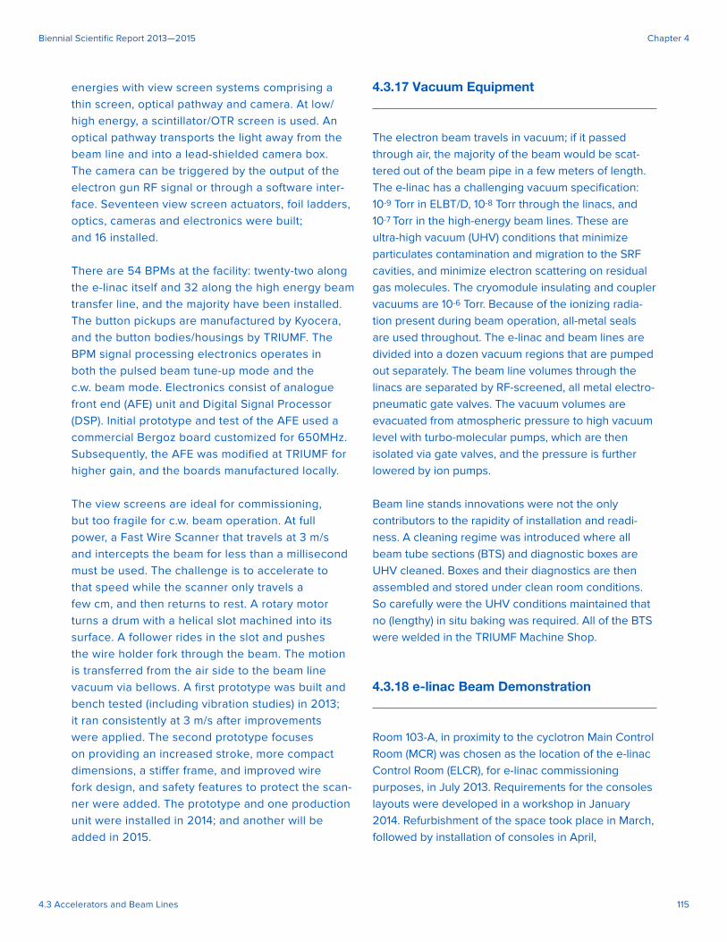
June–September 2014 (see Figure 6)
4.3.16 Beam Diagnostic Equipment
Measurements of beam position, profi le and current
along the beamline are essential for the beam set-up
and for monitoring during the production run. Initial
beam threading is performed with view screens,
followed by trajectory correction with 4-button type
four beam position monitors (BPMs) each measur-
ing in two planes, horizontal and vertical. Electron
beam charge is measured by Faraday cups. The view
screen eff ort was led by the University of Victoria.
Beam profi le measurements can be performed at all
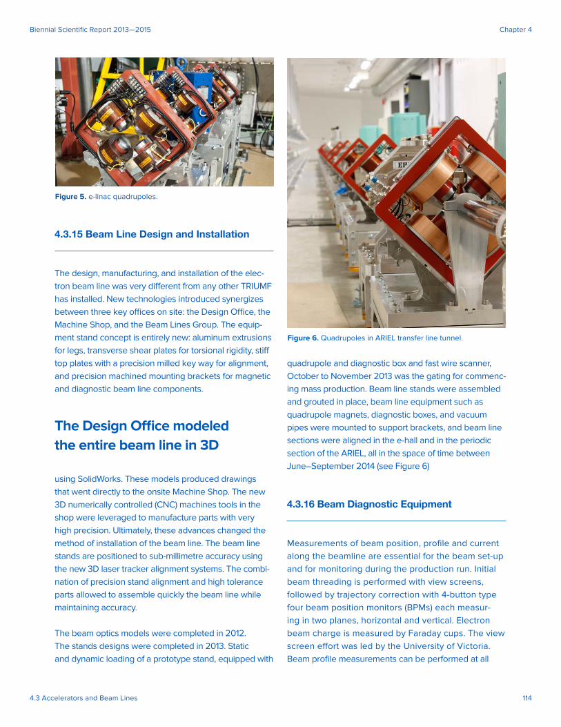
Figure 5. e-linac quadrupoles.
Figure 6. Quadrupoles in ARIEL transfer line tunnel.
4.3 Accelerators and Beam Lines 115
Biennial Scientifi c Report 2013—2015 Chapter 4
energies with view screen systems comprising a
thin screen, optical pathway and camera. At low/
high energy, a scintillator/OTR screen is used. An
optical pathway transports the light away from the
beam line and into a lead-shielded camera box.
The camera can be triggered by the output of the
electron gun RF signal or through a software inter-
face. Seventeen view screen actuators, foil ladders,
optics, cameras and electronics were built;
and 16 installed.
There are 54 BPMs at the facility: twenty-two along
the e-linac itself and 32 along the high energy beam
transfer line, and the majority have been installed.
The button pickups are manufactured by Kyocera,
and the button bodies/housings by TRIUMF. The
BPM signal processing electronics operates in
both the pulsed beam tune-up mode and the
c.w. beam mode. Electronics consist of analogue
front end (AFE) unit and Digital Signal Processor
(DSP). Initial prototype and test of the AFE used a
commercial Bergoz board customized for 650MHz.
Subsequently, the AFE was modifi ed at TRIUMF for
higher gain, and the boards manufactured locally.
The view screens are ideal for commissioning,
but too fragile for c.w. beam operation. At full
power, a Fast Wire Scanner that travels at 3 m/s
and intercepts the beam for less than a millisecond
must be used. The challenge is to accelerate to
that speed while the scanner only travels a
few cm, and then returns to rest. A rotary motor
turns a drum with a helical slot machined into its
surface. A follower rides in the slot and pushes
the wire holder fork through the beam. The motion
is transferred from the air side to the beam line
vacuum via bellows. A fi rst prototype was built and
bench tested (including vibration studies) in 2013;
it ran consistently at 3 m/s after improvements
were applied. The second prototype focuses
on providing an increased stroke, more compact
dimensions, a stiff er frame, and improved wire
fork design, and safety features to protect the scan-
ner were added. The prototype and one production
unit were installed in 2014; and another will be
added in 2015.
4.3.17 Vacuum Equipment
The electron beam travels in vacuum; if it passed
through air, the majority of the beam would be scat-
tered out of the beam pipe in a few meters of length.
The e-linac has a challenging vacuum specifi cation:
10-9 Torr in ELBT/D, 10-8 Torr through the linacs, and
10-7 Torr in the high-energy beam lines. These are
ultra-high vacuum (UHV) conditions that minimize
particulates contamination and migration to the SRF
cavities, and minimize electron scattering on residual
gas molecules. The cryomodule insulating and coupler
vacuums are 10-6 Torr. Because of the ionizing radia-
tion present during beam operation, all-metal seals
are used throughout. The e-linac and beam lines are
divided into a dozen vacuum regions that are pumped
out separately. The beam line volumes through the
linacs are separated by RF-screened, all metal electro-
pneumatic gate valves. The vacuum volumes are
evacuated from atmospheric pressure to high vacuum
level with turbo-molecular pumps, which are then
isolated via gate valves, and the pressure is further
lowered by ion pumps.
Beam line stands innovations were not the only
contributors to the rapidity of installation and readi-
ness. A cleaning regime was introduced where all
beam tube sections (BTS) and diagnostic boxes are
UHV cleaned. Boxes and their diagnostics are then
assembled and stored under clean room conditions.
So carefully were the UHV conditions maintained that
no (lengthy) in situ baking was required. All of the BTS
were welded in the TRIUMF Machine Shop.
4.3.18 e-linac Beam Demonstration
Room 103-A, in proximity to the cyclotron Main Control
Room (MCR) was chosen as the location of the e-linac
Control Room (ELCR), for e-linac commissioning
purposes, in July 2013. Requirements for the consoles
layouts were developed in a workshop in January
2014. Refurbishment of the space took place in March,
followed by installation of consoles in April,
4.3 Accelerators and Beam Lines 116
Biennial Scientifi c Report 2013—2015 Chapter 4
and integration with EPICS in May. The consoles for
the Personnel Radiation Safety system were also
installed in May. The e-linac commissioning team took
over the ELCR in May and began to re-commission the
e-gun and ELBT/D.
The fi nal phase of the e-linac installations and pre-
commissioning was fast paced and exhilarating. The
10 MeV injector was moved from the ISAC test stand
to the e-hall in May, 2014, and injector services includ-
ing cryo and RF were connected by June 1st. The 10
MeV medium energy beam transport was installed in
June, and the 30 MeV momentum analysis beam line
in July. The fi rst accelerated beam, 5.5 MeV from EINJ,
was celebrated on July 19.
The transport to the e-hall beam dump and the peri-
odic section in the ARIEL tunnel were both installed
in September. The Injector Cryomodule achieved 12
MeV acceleration September 23rd. The accelerator
cryomodule, containing one SRF cavity, arrived in the
e-hall August 29th. Immediately following, the EACA
4K LHe distribution and 2K SA return and the EACA
RF waveguides were connected.
The EACA 4K cool down started September 7th,
and the RF input couplers were conditioned to 10 kW
level. The combination of EINJ and EACA cryomod-
ules achieved 23 MeV on October 1st, delivered to
the Faraday cup downstream of the EABD beam
energy analyzer magnet.

Copyright © 2016 TRIUMF
Biennial Science Report 2013–2015
All rights reserved