bi - apps.dtic.mil · ser-611344 final report nh-3a (sikorsky s-61f) flight test program-'d...
TRANSCRIPT

SER-611344
FINAL REPORT NH-3A
(SIKORSKY S-61F)
FLIGHT TEST PROGRAM-'D D--C`ý
BI
"Distz ibution of this Document is unlimited"
"This report has been reviewed by the Naval Air Systems Comand.The findings in this report are those of the contractor and not thoseof the Naval Air Systems Command or the Department of the Navy."
Reproduced byNATIONAL TECHNICALINFORMATION SERVICE
Spdingfio Va. 22151
;.-r PUab~c irujsaa

- Unclassified
DOCUMENT CONTROL DATA - & Dn! . .i...-.- . t1-a i ',t | I as,( ita1iit suia nwat on mo N, Y ,tv1rtd %0tS, i, .sall repo t .. c li-cc)
/Bikorsky Aircraft UnclassifiedA/nited Aixcraft Corp., hý GouP
/Stratford, Conn. r61 6OR T Tilt F
Final Report - NH-3A (Sikorsky S-61F)Flight Test Program
4 -0uL5C IPTI1VE NOTES (Typt-' oiftenort ald lk(•,ci %iv' dcJtex)
Final ReportAt)J FrO# 40 SI (I ir', Sipia~ni. maeddle 110 ,tlal, Intt name-.)
R. M. Segel, D. S. Jenneys W. Gerdes
O, 14 f I'tO I teA L 70. TOTAL NO 0;" $AGF• Sh. NO OF "RES
March 20, 1969 167 74.. ON TT4ACIT O#4 GkANT NO 't., ORIGIJA TO'WS REPORT t4UM~kE•JS5
Contract NOw-64-0528-fb. VROJEC T No SER-611Bhh
9h1. OT74ER R1EPORT NO(S) (,, y ce nu rbors that Inuo) be ass•s {nedthis fc'port)
dS.
l DISTRIBUTIOtl STATEMENT
SDistribution of this Document is unlimited.
IJ 1 SUPPLEMCNTAR• NOTES 112. SPONSORING MILITARY ACTIVITY
Naval Air Systems Command
VI A13STRACT
") This report summarizes a flight test evaluation of the effects of auxiliarypropulsion, wings, rotor solidity, and blade twist on a modified SH-3A helicopterairframe -ith standard S-61 dynamic components. A total of 8, hours of tests exploredperformance, handling qualities, st-esses, vibrations and control loads for eightdifferent configurations.
The primary objective of the program, to extend tests of the compound configura-tion to a maximum safe speed of not less than 200 knots, wc-s achieved. Level flightand dive speeds of 21- and 230 knots, respectively, were reached. At 200 knots, rotorlift was varied from 25 to 75% of gross weight.
Throughout the expanded flight envelope, handling qualities and structural loadsconfirmed predictions with few exceptions. The tests confirmed the ability of thearticulated rotor system to operate satisfactorily in this flight regime and provided /a basis for future aircraft design and for extrapolation to higher speed. /
//
FORM 147 PAGE 1)DD,.NVJ4 3 UnclassifiedS'. 0102-914-6a.(0 Security C':sification

Unclassified _Stcurtty Clas$_____ion_ i__i
I _ LINK A j LINK O LINK C
"• ,t- WO DSROLE W7 ROL.C WT_ ROLE W
SH-3A, S-61F, Compound
Helicopter Flight Tests
Sikorsky
Performance
Load Sharing
Handling Qualities
Vibratory Stress
---
FOR (BCK)Unclass ified
'k (;ET 2)Seut% Cl f il

SSlkorsky Al!ircraft • -. 0.-, .- •- I-,I
TITLE: Final Report - NH-3A (Sikorsky s-61F)Flight Test PrograT
REPORT NUMBER: SER-6113)414
PREPARED UNDER: Item 3(g), Contract NOw-64-0528-r
REPORT DATE: March 20, 1969
REPORT PERIOD:
This repor Is applicable to the following aircraft model(s) and contract(s):MODEL CONTRACT
1IH-3A NOw-64-0528-f'
Distribution of this Document is unlimited.
This report has been reviewed by the Naval Air SystemsCommand. The findings in this report are those of the contractorand not those of the Naval Air Systems Command or the Departmentof the Navy.
S....... .- RM, SegelJ D. S. Jenney. W. Gerdes, et al.
o by E. A. Fradenburgh, Assistant Chief of Advanced Research
REVISIONS
CHANGIED REVMWE ADDED DELETED omtI0 AT PIREV 3 PAGIE(S) PAGIE(S) PAGE(S)DSRIIODAE PRVA
13 DSJ All -- 155 To comply with AVLABS request. 11/3/70'! fIRKB thru
160
REVISIONS CONTINUE) ON NeHT PAUi
S 28 REV A (M)

ABSTRACT A
This report summarizes a flight test evaluation of the vi "s Gof
auxiliary propulsion, wings, rotor solidity, and blade twist on %. fied
SH-3A helicopter airframe with standard S-61 dynamic components. A total
of 88 hours of tests explored performance, handling qualities, stresses,
vibrations and control ]oads for eight different configurations.
rThe primary objective of the program, to extend tests of the compound
configuration to a maximum safe speed of not less than 200 knots, was
achieved. :jevel flight and dive speeds of 211 and 230 kncts, respectively,
were reached. At 200 knots, rotor lift was varied from 25 to 75% of gross
weight.
Throughout the expanded, flight envelope, handling qualities and struc-
tural loads confirmed predictions with few exceptions. The tests confirmed
the ability of the articulated rotor system to operate satisfactorily in
this flight regime and provided a basis for future aircraft design -and for
42extrapolation to higher speed.
ii
--- -

FOREWORD
•- This report sumniarizes the results of a compound helicopter flight
investigation conducted by Sikorsky Aircraft. The program was jointly
funded and monitored by the U. S. Naval Air Systems Command (NAVAIRSYSCOM),
and U. S. Army Aviation Materiel Laboratories (AVLABS). Due to the large
number of configurations and test conditions and the duration of the flight
investigation many individuals contributed to the program.
The program was monitored for NAVAIRSYSCOM by Messrs. Frank O'Brimski
and John Snoderly. and for AVLABS by Messrs. Richard Adams and Richard
Dumond.
NH-3A project engineers at Sikorsky were Messrs. F. de Sibert and
J. E. Nkdin. Program technical. direction was provided by Mr. E. A.
Fradenburgh. Additional Sikorsky Airoraft personnel closely associated
with the program Wiere Messrs. G. B. Chesley, G. M. Chuga, T. M. Coonax.,
P. J. D'Ostilio, R. R. Fenaughty, W. Gerdes, B. Gr.aham, Jr., D. S. Jenney,
- W. H. Kimes, J. Kotkowski, D. F. Perrault, C. M. Reine, A. J. Ruddell,
R. M. Segel, and P. VonHardenberg.
- iI
iii
_ _ _ _ _ _ _ _ _ -i~. -

TABLE OF CONTENTS
Page1
ABSTRACT i. . . . . . . . . . i
FOREWORD . . . . . . . . . . . . .
LIST OF ILLUSTRATIONS . . . . v. . . .
LIST OF TABLES . . . . . . . ix
LIST OF SYMBOLS . ... . . . x
INTRODUCTION . . . . .
DESCRIPTION OF'VEHICLE . . .. . . . -. 3
DIMENSIONS AND GENERAL DATA ... . . . 5
TEST PROCEDURES . . . .. . . . . .. 8. .
RESULTS AND DISCUSSION. . . . . . . .. . 11
Operating Envelopes - Aircraft . . . . . .. . .
R.over Per±ormance .o . . . - • • • • .
C Aircraft Drag . . . 15
SDifferential Wing ift 16-
- eratýing Limits main -Rotor.Structural Loads * : * * .
I:• '. • • . .. . . . -22
. yi.igS . . . . * . . 30
CONCLUSIONS- • . . .. . . . . .*5
" RECOMMENDATIONS . . . .. . . . . 36
-REFERENC3. .. . . . . . . . . 37
APPENDIX
I j/12 Scale Model Wind Tunnel Data; 123 -
II' Test Instrumentation .. . . ... . 131
III Typical Flight Test D!ta. . .. . • • 1144
iv
I: -,+.e •

TI.ST OF ILLUSTRATIONS
Figure Pg
1. Production SH-3A Helicopter • 46
2. NH-3A - Helicopter With Jet; . . . . . .. . 47
3. NH-3A - Helicopter With Jets - General Arrangement • • 48
4. NH-3A Compound Helicopter Configuration .. . . 49
5. NH-3A Compound Helicopter - General Arrangement . . . 50
6. NH-3A Helicopter - General Arrangement. • • • 51
7. NH-3A Level Flight Envelope for Various Aircraft Configura-tiohs, Elevator Settings and Horizontal StabilizerIncidences . .. . . . 52
S8. Hover Performance - Effect of Blade Tvist (Basic-Helicopter, Five Main Rotor Blades) . . . . 60
9. Hover Performance - Effect of Rotor Solidity ( -4 DegreesTist, With -Jet Pods) . . . . . . . . . . 61
10. Hover Performance - Effect of Wing ins ~al!Ation (Five Main
Rotbr Blades, -4 Degrees'Twist) . . • . . • 62
11-. LifDrag .. s. . . . . . . 63
12. Lateral Control Position Versus Airspeed o. .. 65- - .... 3•.t Differential Wing Lift Test Installation . . . . . 66
* 14. 'Wing -Lift Distribution . . . 67-
15. Rotor Operiting Envelope fcý ' Various Airspeeds and Rotor" Confi'rtiozis an 660 FPS Rotor Tip Speed . . . 69.
S"16. Compressibility Mapping Conditions . . 78
17. Dyfamic- Behavior During Blade Tip Excursion at 190 Knots . 79
18. Blade Pitching Moment Coefficient Versus Angle of Attackand Mah Number . . . . . . . . . . . 80
19. Afialy:ticai Reproduction •of Blade Spread . . 81
'20. Control Loads at Points Below Theoretical LowerO Stall Limit . . 82
i v
A' i t N ~m~l~m •••I N tm 0g jW N~lgNta e • on um8 • I m mdolgm 88 Jlmd l -Z _ .. ...

Ftigiure. . . . . . Page
21. Change in-Control Loads at Points Above Theoretical 8• ~Stall Limit . ..... 83
22. Control Loads Correlation With CH-53A . . . .. . 84
23. Control Loads Correlation With CU-3C . . . . . 85
24. Control System Load Contours at 175 Knots (Five MainRotor Blades, -8 Degrees Twist) . . . . . . 86
25. Main-R6tor Rotating Scissors, Vibratory Load ýWith Wingsand Jets, Five Main Rotor Blades, -4 Degrees Twist) . 87
26. MainRotor Stationary Scissors, Vibratory Load (Without_Winks, Six Main Rotor Blades-, -4 Degrees Twist) . R 88
27. Blade Stresses at 70 Percent Radius Versus Airspeed (FiveMain Rotor Blades, -4 Degre-es Twist) . . . 89
28. Effect of Rotor Lift and Airspeed on Blade Stress at 70Percent Radius-, (Five Blades, -4 Degrees Twist.) 90
29, Effectof Number of Blades On Blade Stress With AuxiliaryPropulsion,, (-4 Degrees Twist) . . .. . 91
30. Effect of Twist, on Maximum Stress; (With AuxiliarySProPuiSion,- Six Main Rotor Blaces) . . .. . 92
-1 - -3!. Effect of Rudder Deflection on Tail Rotor Stresses . . 93
-[ 32. Ef-eCt. of: Number of Blade§s' and Blade, Twist- on Fdiselage4 Vibration . . .. 5. . . •. . 94
3 NH--3A Cockpit Response Versus Frequency . -. 95,
34. Effect of Number of Blades on Transmission Support 9SStressez at Left Forwad- Fitting . . - .. • * 9
-,;P,- 97-2•:•;" 35. Effect of Rotor Unloading on Cockpit Vibration ,. -.
36. V-N Diagram for Variobu Aircra•t Configýratiohis . .
S37. -Lateral -Directional Static Stability at 125 Knots A-FiveSMain-Rotor Pla-des, -8 Degrees, ýZero Degreej.HT) 101
38. Correlation of Steady State Flight Parameters, (With-Wings"and Jets,,Five, Mai, Rotor Blades, -4 Degrees Tvist, -15 10Degrees 6e Zero Degree 6f , 5 D10reesi)•
v!I

[ ~ '-~ Figure Pg39. Effect of Drag Reduction on Steady State . m~tPrs.
(With Wings and Jets, Five Main Rotor Blades, -4 Degrees
Twist, Zero Degree 6e' 4 Degrees 6f, Zero Degree iiT) * . 105
1s0. Effect of Speed on Horizontal Tail Loading . . .. . 107
41. Effect of Wing on Steady State Flight Para.meters, (With
Jets, Five Main Rotor Blades, .-4 Degrees Twist, Zero DegreeS-15 Degrees f, 5 Degrees iHT) ... 108
h2. Effect of Wings on NH-3A Dynamic Response of FuselageAttitude to a Longitudinal Pull and Return at 120 Knots,(With Jets, Five Main Rotor Blades, -8 Degrees Twist,Zero Degree 6e, Zero Degree i HIT) .. . . .110
43. Correlation of Dynamic Response of Fuselage Attitude to aLongitudinal Pull and Return-at 120 Knots,. (With Jets, FiveMain Rotor Blades, -8 Degrees Twist, Zero Degree 6e' ZeroDegree i HT) ..... e I
44. Effect of Solidity on Steady State Flight Parameters,Without Wings and Jets, -8 Degrees Twist, Zero Degree 6 e'Zero Degree iHT)I . .. ..- 113
•,) 45. Correlation of Dynamic Response of Fuselage Att'itude to aLongitildinal Pull and Return at 120 -Knots, (Without Wings,With Jets, Six Main Rotor Blades, -8 Degrees Twist, Zero-Degree6 , Zero Degree .) . . . . . . . 115
e HT
46. Comparison of NH-3A and SH-3A Dynamic Response . . . . 116
47. Effect of Elevator Deflection On ,Stekdy State Flight Para-meteris-, -(With Wings and Jets, Five Ma•in Rotor Blades, -8 4Degrees Twist, 4 Degrees 6,, Zero Degree iT) .i. t117
HT48. Erfect of Rudder Deflection on Steady State Flight Para-
meters, (With Wings and Jets, Five Main Rotor'Blades, -4Degrees Twist, Zero Degree-6 , Zero Degree 6., ZeroDegree i .. . . . .. . . . .. . 121
149. _1/12 Scale Wind Tunnel Model - NH-'3A. . . . .. . 125
50. Effect of Configuration on Longitudinal Characteristics,l/i2Sdale Airframe Model . . .. . . . . . .126
51. Effect of Flao Deflection on Longitudinal Characteristics,-.1/12 Scale Airframe Model .. . . . . . . 12T
52. Effect of Eievator Deflection on Longitudinal Charact 'r-istics, 1/12'Scale Airframe Model . . . . . . . 128
vii

53. Effect of florizontal Tail Incidence on LongitudinalCharacteristice, 1/12 Scale Airframe Model. . 129
54. Effect of Fuselage Attitude on Lateral and Rolli
Characteristics, 1/12 Sca16 Airfrtime Model . . .130
55. Airspeed Calibrations . - . . 134
viii

LIST OF TABLES
Table__age
I Data Flights . . . . . . . . 38
II NH-3A Parachute Drag Breakdown • • • 145
MII Control Rigging . . . . .. . . . 135
IV Oscillograph Measurements . . . . . . . . 136
V Photopael- Measurements .. . . . 1.4
VI Instrumentation Accuracies • •
VII Typic-1 Flight-Test Data . . . . . . . .
ix

LITST OF SYMBOLS
A rotor disc area, square feet
Als lateral cyclic control, degree.s
als longitudinal flapping, degrees
b number of blades
Bis- longitudinal cyclic control, degrees
b1s lateral flapping, degrees
c chord, feet
C ~drag/dynamic pressure, sqiware feetCD
C lift/dynamic pressure, square feetL
rolling moment/dynamic pressure, feet cubed
Cpitching moment/dynAmid pressUre,-feet, cubedM
control: load-coefficient
2PJ.
C power coefficient-P
550 -SHP
pA(SR
C torque coeaff icie~nt
C
-C drag torque coeff-ficie~it
9-D~
--
4- --

C.. weight coefficient
Wc G.W. -3
C
CW = , ;^,A(f)2+
CAS calibrated airspeed, knots
SCG center of gravity, inches
cPI4 cycles per minute
DV vertical drag (download) on airframe due torotor downwash
f equivrleno flat plate area, square feet
fps feet per second
g -acceleration of gravity
G.W. -gross weight. pounds
H density altitude, feetD
stabilizer irncidence, degrees
A.S indicated .airspeed, knots
LIN nautical miles per hour.i knots
I -Llift, pounds
rotor lift,-pounds
itblade cont-kol -horn ari. length,- feet
M M~ich number
nblad. root pitching maent
'N flight load factor
NR rotor speed, RPM or percent _i00% 203 RPM
PSI pounds per square inchP -main rotor push rod vibratory control load, poundsV
"" q dynamic pressure
_q =pV
xi
- ,

torque, foot -pounds
1) rotor radius, feet
RPM revolutions, per- minute
SHP shaft horsepower
SHPMR main rotor shaft horsepower
V triue airspeed, feet -per second
V^ true airspeed (TAS), knotsT
fuselage angle of attack, degrees
6 fflp deflection, degrees
6- elevator deflection, degreese
6- rudder deflection, degrees
0° collective pitch at -the blade cuff, degrees
0
C .75 collective pitch at the-75% blade radius, odegrees
- 01 linear blade twist'.,- degrees
adVance ratiob
-~> 'P air -dezi4,t'y'
" • o ~~rotor-S solidity•.
/4 Sbe
SIUR tiyý speed, feet per second
xii

INTRODUCTION
Sikorsky Aircraft, with the support of the U. S. Naval Air Systems
COmmand and U. S. Ay.y Aviation Materiel Laboratories, has conducted a
flight research program to demonstrate an expanded flight envelope for
rotorcraft. -
The conventional pure helicopter has limitations in forward flight-
caused by stall on the retreating blade. Both the lifting and propulsive
capabilities of the rotor decrease with increasing speed. Compounding
"the helicopter, by adding a fixed wing and auxiliary propulsion is, there-
fore, a logical meaus of increasing speed potential. Theoretical research
and wind tunnel tests of articulated rotors have shown that compound
helicopters shoald be capable of practical speeds at least 100 knots faster
than the pure helicopter. The NIf-3A research program was prompted by the
need- for an aircraft of operationally useful gross weight to demonstrate
these improved capabilities and to confirm the theoeetical work under
full-scale conditions.
The Navy/Sikorsky SH-3A, whieh -. is chosen as the base aircraft for
"the research program, was designed for a cruise .4peed of approximately"135 knots. It was known, however, that the rotor system of ta.is aircraft
was capable of much higher speeds. In February 1962, the SH-3A, with a
special skid landing gear to reduce drag and weight, set a world's
absolute speed record of 210 miles per hour, or 183 knots. This waf- an
imprestive achievement for a pure helicopter, surpassed as of the date
of this report only by the SUD/Super Frelon using a similar system
designed by Sikorsky Aircraft. The speed record set by the SH-3A, however,did not repreaent actual mission capability. The aircraft was stiipped of
all equipment unnecessary for the flight, and payload was nearly zero.
-Aircraft vibration, blade vibratory stresses, flying qualities, and maneu-
vering capability at maximum speed were satisfactory for establishing the -A
record, but they were not satisfactory for operational use.
41
...................................................................... -

The major objectives of the Nii-1A flig'9 search5"&4 prcgr-mwrV . (1 Demonstration of improved, aircraft capability. Speeds
of at least 200 knots were desired with good useful load.,
low vibration, low stresses, improved flying qualities,
and good maneuverability.
(2 Determination of- the ef fect of -a number. of deisign variables
oil 4irci-aft chara~cteristic's. Eight aircraft configurationswere testeýd. Th aibe nlded the number of rotor
blades (five and six) , two valuies,. of "blade twist (-0and 8i
a-wing (on-and off), and auxiliary jet engin'es (on-,and off).
(,3)- ExpSerimental -dete =na~tion oi rotor capability -at- ihsed
The aircraft. was designed to be use&d' s a flying wind tunnel.
The -wing' and, auxil~iary propu3 sion per~mitted operation of' the
-ma~in rotor, over a wide-range of conditi~ns so.-tha~t envelopes
C.of.rotor- lift, propulstive force, Ahdpoiier lo6ading -capiability
C-ctl be established. Th-is- also permitted determina~tioni ofrotor control p-iower,* fla*pping, dyaibhvior, androt~or-
-- wing- IiterI'erence-:over A Videi range -of -flight conditions-.,
The -3 research-program -hii be en succesifuilin demonstrating, an
imroved: capability- f or rotar;y win~g aircraft. Valuaible reseirch data- weregeeated' toperit th tino ftr h~ erformanice helicopteirs' and
-compounds. All of the major ob1jectbive of'- theý programý wereiachieveda.
2

DESCRIPTION OF VEIIICLE
The NH-3A (Sikorsky model S-61F) high-speed research helicopter is
a modified SH-3A helicopter, Bureau No. 148033. A production SH-3A is
shown in Figure 1.
The military electronics, sonar, armament, shackles, hoist, sonar
seats, and automat!- flight control system were removed from the aircraft,
and the following changes were made:
WING: A wing of 170 square feet was installed in the "shoulder" position,
with the aerodynamic center slightly aft of the rotor centerline. A
full-span plain flap, capable of up or down deflection, was provided to
trim the wing lift independently of fuselage angle of attack. The flap is
controllable in flight through a "beeper" arrangement, with a normal rate
of 3 degrees/second and an emergency "up" rate of 30 degrees/second.
AUXILIARY PROPULSION: Two Pratt & Whitney J-60-P2 turbojets, mounted in
T-39 "Babreliner" nacelles, were installed on either side of the fuselage,
outboard of the landing gear sponsons.
TAIL CONE: A streamlined tail cone replaced the SH-3A aft fuselage. This
modification provides a 17 degrees flapping clearance between the main
rotor ~and the tail cone compared with 13 degrees for the SH-3A.
HORIZONTAL TAIL: A Cessna T-37 stabilizer with an added constant chord
center section was installed. The incidence was ground adjustable. A
"beeper" arrangement provided Sn-flight elevator control with a rate of
2 degrees/second.
VERTICAL TAIL: A large vertical tail with rudder was provided. The
rudder deflection was controlled in-flight by a "beeper" with a rate of
2 degrees/second.
4 ROTOR HEAD: The automatic blade folding herdware was removed to reduce
drag. A "beanie" fairing was installed on the rotor head.
3
Vi

[ • OT.L ('OO1I.FR" A CI-3W/VII-3A oil cooler system was incorporated in the
-C main rotor pylon area.
FUSELAGE: The aft cargo door, sonar well hole, and doppler antenna were
eliminated and skinned over. An emergency exit panel was provided on
the right-hand side of the cabin. The cockpit side windows were made
fixed but jettisonable. The cockpit glass was reinforced or, in some
areas, skinned over.- The chin lines of the flying boat hull were rounded
to provide a better streamlined nose shape.
LA1NDING GEAR: The open-well sponsons on the SH-3A were replaced with
more streamlined sponsons with doors which completely enrlose the main
gear in the up position. The landing gear tread was reduced from 13 to
10 feet.
The following table gives dimensional information pertinent to ti.
NH-3A (s-61F).
%S
C

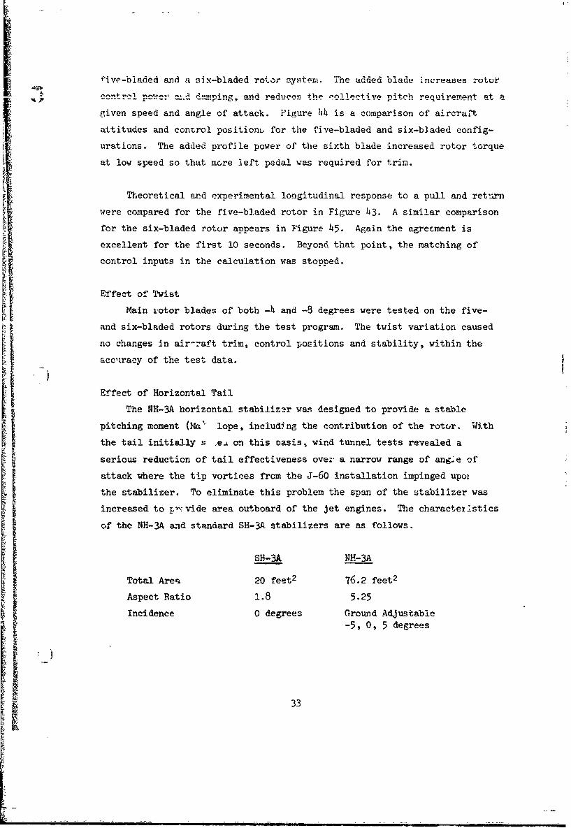
_ DIMENSIONS AND GENERAL DATA
Main Rotor:
Diameter 62 feet
Norial tip speed (100% N ) 660 fps.
Disc area 3019 ft. 2
Blade chord 18.25 in.
Airfoil section NACA 0012
Numnber of blades 5 or 6
Solidity, bc .0775 or 0.0937
2-R
Blade twist (center of rotation to tip) -.40 or -80
Root cutout (% radius of first bladepocket) 15%
Hinge offset 1.05 ft.
Articulation Full flapping and lag
Blade weight moment about flap hinge 2876.1 ft. lb.
Blade moment of inertia about flap hinge 1703.5 ft-lb-sec2
Tail Rotor:
Diameter 10 ft. 4 in.
Normal tip speed 660 fps.
Blade chord 7.34 in.
Airfoil section NACA 0012
Number of blades 5
Solidity .188
Blade twist 09
Hinge offset .323 ft.
Articulation flapping only
Pitch flap coupling (delta-three angle) 45 0
Wing:
Span 32 ft, 0 in.
Area 170 ft. 2
Exposed area 137 ft. 2
Taper ratio (tip chord/theoreti"alroot chord) 0.5
5
Sl im i-irai • mu lim~mi ml m ~ m m i m• wm 'i mmw• i-ml~wi i i iiiiii- - :- m • i-3

Wing (continued):Tip chord 42.5 in.
Mean aerodynamic chord 72.8 in.
Twist 0°0
Dihedral 00
Sweep of 26% chcrd line A00
Aspect ratio 6.04
Flap area (aft of hinge line) 29.8 ft. 2
Flap chord (aft of hinge line) 26% wing chord
Airfoil section NACA 63 2 A 415
Tail Surfaces:
Horizontal tail area 76.2 ft. 2
Horizontal tail span 20 ft. 0 in.
Elevator area 10.8 ft. 2
Horizontal tail airfoil section NACA 0010 modified
SVertical tail area (above WL 158) 44 ft. 2
Rudder area 8.6 ft. 2
Fuselage:
Length 56 ft. 0 in.
Cabin width 7 ft. 0 in.
Landing gear tread 10 ft. 0 in.
Wheel base 34 ft. 7.5 in.
Rotor head height 15 ft. 5.5 in.
Weights:
5 Blades 6 Bladeslbs. lbs.
R~tor group (6 blades) 2517.5
Rotor group (5 blades) 2097.9Wing group k chord Sta. 278.0 1014.0 1014.0
Tail group 350.9 350.9
Body group 2520.6 2520.$
Alighting gear 811.2 811.2Eng. section (T-58) 141.7 141.7
6

F
Weights (continued): 5 Blades 6 Blades
1bs. lbs.
Eng. sectiun (J-60) 423..4 421.4
Powerplant group 2608.6 2608.6
Fixed equipment group 2910.5 2910.5
Weight emApty 12876.8 13296.4
Useful load 6123.2 5703.6
Design gross weight 19000.0 1900C.0
Powerplants:
Main propulsion unit
Two General Electric T58-GE-8B turboshaft engines with the followingratings at sea level standard day conditions:
Ratings, Shaft hp Power Shaft Max. SFCOutput R.P.M. lbs/SHP/hr
Military - i250 19,500 o.61
Normal - 1050 19,500 o.64
Auxiliary propulsion unit
Two Pratt & Whitney J-60P-2 turbojet engines with the followingstatic ratings at sea level standard day conditions:
Ratings Jet Thrust Maximum Max. SFCS lbs. R.P.M. lbs/hr/lb
Military 2,900 16,400 0.930
Normal 2,570 15,750 0.905
7 i

Flight testing of the S-61F research aircraft was initiated on
May 21, 1965, following satisfactory completion of proof load, shake,
e and tie-down tests. A total of 113 flights involving 88.2 hours of
flight were completed during the test program which terminated on
May 8, 196T. Flights were conducted at a density altitude of 3000 feet,
except for the hovering, autorotation, and airspeed calibration flights,
which required specific altitudes. A suimary of the flights accomplished
during the program is given in Table I.
PRELIMINARY EVALUATION
For the initial phase of the test program the aircraft was configured
as follows: two J-60 turbojet engines, a horizontal stabilizer with +5
degrees of incidence, and five main rotor blades with -4 degrees of twist.
A photograph of this configuration is presented in Figure 2 and a general
arrangement in Figure 3. IF
" C Initial flights were conducted without auxiliary jet thrust to provide
pilot familiarization and preliminary evaluation of the basic characteris-
tics of the helicopter, including handling qualities, performance, stress,
and vibration levels.
THRUST AUGMEUATION
Following the preliminary flight test phase, jet thrust augmentation
was used to investigate higher speeds. Jet thrust augmentation was applied
by the following "standard" procedure.
1. Set the J-60 jets at idle.
2. Trim the aircraft in level flight at a specifiedforward speed, 100 percent NR, with the main rotorcollective pitch control as required.
3. T.Lock the collective pitch.
4. 7ncrease Jet thrust as necessary to attain higher* • ,,-vard speeds.
Q When this procedure was followed, a high collective pitch and hi'.
rotor shaft power level resulted from an initial high speed trim condition,
8
.4 I ! I I I I I ~ i I I ~ i I I

}7
. ma.i.m. collec'yive pitch and rotor power resulted from an initial
trim speed near the minimum power speed of the helicopter (70-80 knots).
,To establish a low collective pitch, low rotor power condition, the air-
craft was first trimmed at 80 knots, and then the collective pitch was
lowered to the prescribed value while increasing jet thrust as required to
maintain speed and altitude.
COMPOUND CONFIGURATION
A photograph and general arrangement of the compound configuration
are shown in Figures 4 and 5. After initial flights in this configuration
for aircraft familiarization, several combinations of elevator and flap
settings were investigated to vary rotor/wing load sharing, and establish
the maximum speed of the configuration. A stabilizer incidence of zero
degrees was selected and used for the remainder of the program. A maximum
true airspeed of 221.8 knots (212.2 knots CAS) was achieved with a rate of
descent of 1300 feet/minute. The basic test procedure was the "standard"
procedure described above. During testing of the compound configuration
with -4 degree twist blades, several additional evaluations were completed,
including the following:
1. Investigations of a blade tip excursion phenomenon associated
with advancing blade Mach number and low frequency vertical
response characteristics of the fuselage.
2. Evaluation of asymmetric wing lift including in-flight photo-
graphs of tufts installed forward of the leading edge of the
wing.
3. Two stages of drag reduction at Flight No. 30 and Flight No. 40
with improved wing root 1, Ing, sealing of the gaps in the wing
flaps, and general clean-up. A maximum level flight true air-
speed of 210.9 knots (199.3 knots CAS) was achieved with this
configuration.
BLADE TWIST EVALUATION
The effects of blade twist on rotor stall characteristics, blade
9

trs• Tcls .....advancing blade compressibility, and aircraft performance
were investigated through tests of both -4 degree and -8 degree twist
main rotor blades. The aircraft configuration remained unchanged except
for the rigging changes necessary with the increased blade twist. Twist
effects were evaluated on both the helicopter and compound configuration
and with both 5 and 6 blades.
ROTOR SOLIDITY EVALUATION
The thrust augmented helicopter (without wings) was tested with both
five and six-bladed rotors to determine the effects of increased solidity
ratio on aircralt performance, handling qualities, vibration, and -,tress: levels.
In addition to establishing the boundary limits for the six-bladed
configuration, static and dynamic stability maneuvers as well as coor-
dinated turns were accomplished. Hover performance data were also recbrded
with both the -4 degree and -8 degree twist main rotor blades.
S C PURE HELICOPTER CONFIGURATION
The aircraft was configured for the pure helicopter tests to provide
baseline data by removing the jet engine pods and installing an aerodynamic
fairing outboard of thL sponsons. The general arrangement is shown in
Figure 6. Flight testing provided baseline data in the areas of aircraft
performance, handling qualities, vibration, and structural loads with both
the -); degree and -8 degree twist rotor blades. Flight conditions included
level flight, autorotation, and .dynamit stability maneuvers. Hover perfor-
mance data were also recorded with both the -4 degree and -8 degree twist
main rotor blades.
AI
10

RESULTS AND DISCUSSION
OPERATING ENVELOPES-AIRCRAFT
The achieved operating envelopes of the eight aircraft configurations
are shown in Figure 7a through Th in terms of airspeed and rotor shaft
horsepower. In each case, the helicopter flight mode (jets idle or
removed as applicable) is presented as ý solid curve. In addition,
Figures 7a through 7f show points achieved with jet thrust augmentation
at various main rotor collective pitch settings. These data are also
listed with values of jet thrust and rotor lift and rotor drag in Table VII.
Factors which limited the aircraft operating envelopes are discussed in
the succeeding paragraphs.
Helicopter With Thrust Augmentation
a. Five Blades, -4 Degrees Twist
S) The envelope for this configuration is shown in Figure 7a.
With collective pitch settings at the 80 knot value or lower,
the high speed boundary was defined by available jet thrust.
The aircraft was flown in level flight autorotation at full
low collective at 162.3 knots CAS and 5200 pounds of jet
thrust.
At collective pitch settings above the 80 knot value, forward
speed was limited by retreating blade stall, indicated by
aircraft roughness and elevated control loads. Main rotor
transmission support stresses indicated elevated levels at
high shaft horsepower, but this condition was considered
hcceptable for short periods of operation.
b. Five Blades. -8 Degrees Twist
The envelope for this configuration :s shown in Figure 7b.
®r1

r•z inrc-ased b!-ade twist provided a greater rotor
propulsive force capability, permitting a slight expansion
of the high power portion of the envelope. A maximumspeed of 196.2 knots (207.0 knots TAS) was attained at the
100 knot collective pitch setting. Further increases in
collective pitch were limited by aircraft roughness, high
main rotor control system loads, and high stress levels at
the forward transmission support fitting. The aircraft
was also flown as an autogyro with full low collective, at
speeds from 85 to 167 knots CAS.
Compound Configuration
a. Five Blades, -4.Degrees and -8 Degrees Twict
The envelopes for these configurations are shown in Figures
7c and 7d, A maximum level flight calibrated airspeed of
199.3 knots (210.9 knots TAS) was achieved at the 130 knot
C.collective pitch setting, utilizing 5485 pounds of jet
thrust and 1668 main rotor shaft horsepower with the -4
degree twist blades.
In the compound configuration, the upper portion of the speed
boundary was extended to higher speeds compared to the
wingless configuration. This expansion was possible because
of the additional Ilt-. produced by the wing. Reduced rotor
lift requirements permitted additional rotor propulsive force
for a comparable degree of rotor stall. Main rotor control
loads and vibratory stress levels at the transmission attach-
mernt fittings showed considtrable reduction in magnitudes
as the main rotor loading was decreased. Available jet
thrust was the limiting factor in establishing the level
-' flight speed boundary for the compound configuration.
I I ~ i I II~ I IIII !

Six-Bladed Helicopter With Thrust Au-entati-.,n
The envelopes established for this configuration with-4 degree and -8 degree twist blades are presented
in Figures 7e and 7f. The n/rev, aircraft vibration
levels and transmission attachment stress levels were
considerably reduced with the six-bladed configuration
arnd presented no problem at high main rotor shaft horse-
power. However, the stationary scissors link of the
main rotor control system exhibited higher loads than
with the five-bladed rotor at high collective pitch
settings.
Full jet thriit was utilized with the 120 knot collective
pitch setting to achieve a maximum calibrated airspieed of'
204.5 knots (215.0 knots true airspeed) with -4 degree
twist blades. This condition was obtained utilizing 5690
pounds of jet thrust and 1390 shaft horsepower. Further
Q incr~ases in collective pitch were limited by the high
stationary scissors loads. With lower values of collective
pitch, maximum forward speeds decreased and jet thrust
became the limiting factor.
Pure Helicopter
Figures 7g and 7h present the level flight performance of
the pure helicopter configuration. Data points are shown
for zero stabilizer incidence and elevator settings of zero
and -2 degrees. As illustrated in Figure 7g, a power-limited
maximum level flight calibrated airspeed of 152.0 knots
(160.2 knots true airspeed) was obtained with the -8 degree
twist rotor blades while utilizing 2440 shaft horsepower
from the T-58 engines. Under similar flight conditions with
the -4 degree twist blades installed, a speed of 144.0 knots
d10
13

calibrated airspeed (152.3 knots tr-ae airapeed) was
C obtained us-Ing 2390 shaft horsepower.
HOVER PERFORMANCE
In addition to accomplishing the primary investigation of high
speed flight, a limited study was conducted to determine the effect
of each ,; t•he configuration changes on NH-3A hover performance.
The effect of blade twist is shown in Figure 8, which compares the
hover performance of five bladed rotors, having -4 degrees and -8 degrees
twist. The lower (solid) curve was derived from Sikorsky main rotor
test stand data for -8 degree twist blades. Experimentally determined
tail rotor power, fixed losses, and 3 percent vertical drag have been
added. This curve correlates well with the NH-3A hover data for -8
degree twist blades.
The Goldstein-Lock methoo, (Reference 1) was used to estimate the
increment in power due to the change in twist. This increment of 2%
C •in power was applied to the -8 degree data to predict the performance
of the -4 degree twist rotor shown in the upper cuare. The test results
appear to confirm the predicted penalty.
A comparison of the NH-3A hover data with 5 and 6 blades (of -4
degrees twist) is shown in Figure 9. The performance increment due to
the change in solidity, estimated by the Goldstein-Lock method, is also
shown. The five blade data were acquired in ground effect and corrected
to the OGE conditions. With six blades, the aircraft was flown at a
lower gross weight in order to hover OGE.
The vertical drag effect of the wing and sponson/engine installation
is shown in Figure 10, which compares hover data for the pure helicopter
(from Figure 8) and compound configurations. At constant power, a 6percent reduction was required in the compound helicopter gross weight.
This increment is the vertical drag contribution of the wing and
sponson/e;ngine installation.3 (

Aircraft drag has been estimated using measured values of jet thrust,
main rotor thrust and torque, and main rotor drag calculated by the method
of Reference 2. The lift-drag polars resulting from this procedure are
shown in Figures lla and b for the jet augmented helicopter and the full
compound configuration respectively. The improvement at 160 knots due to
the drag reduction program is approximately two to three square feet.
The drag reduction modifications performed after flight number 39
included the following items:
1. Enlarged wing-fuselage junction fairings.
2. Reworked landing gear fairing.
3. StreamLined tail rotor gear box nose section.
4. Covered various openings on the aircraft.
5. Elimination of various antennae.
Equivalent parasite area was found to increase with forward speed, parti-
ctlarly in the full compound configuration. The reason for this speed
•) dependency has not been firmly established, but a probable source of the
drag increase is spillage from the T-58 engine air intakes. A decrease
in accuracy of the rotor performance calculations with forward speed may
also contribute to the apparent drag increase; Correlation of the full-scale wind tunnel tests of an H-34 rotor system, reported in Reference 3,indicated that at lift and torque coefficients similar to NH-3A flight
test valuet;, the theory was increasingly optimistic with forward speed.
This would result in an apparent increase in airframe parasite area.
Table II presents the estimated parasite drag breakdown of the full
compound configuration at 160 knots. These data are based on flight
tests of the SH-3A and wind tunnel investigations, with analytical
corrections where applicable.
The J-60 nacelles as-installed were found to be producing nearly
three times the estimated drag. In addition, local separated flow, which
was observed on the wing and landing gear pod fillets and on the wing
15
I
flap, is believed to have ,-aused penalties as shown. It is notable that
r the di g of the pure helicopter (without wings and J-601 3) . reducd
20 percent below that of the SH-3A even though the rotorhead was unmodi-fied except for remjoval of blade fold parts, and the cockpit canopy
shape and engine inlets were left unchanged. Improvements in these
areas would be particularly fruitful at speeds above 200 knots.
-DIFFERENTIAL WING LIFT
During initial tests of the compound configuration, wing instra-
mentation indicated that the left wing lift was higher than the right.
This finding was substantiated by examination of lateral cyclic pitch
data. !'igure 12 shows that with the wing installed an increment of
left lateral stick, which increased with forward speed, was required to
Sbalance the wing rolling moment.
To further define bhe wing lift distribution, tufts were installed
on a wire mounted 8 inches forward of the wing leading edge. The test
installation is shown in Figure 13. Local angle of attack was deter-
mined from film records of these tufts, taken in various flight condi-
tions. Wing lift distributions were then determined from the experi-
mental angle-of-attack and two-dimensional characteristics of the wing
airfoil (NACA 63 2 A415). While there was some scatter in the data, it
was generally found that very low angles of attack were developed on the
inboard portion of the wing (above tbh sponson). In addition angles ofattack on the right wing were lower than on the left. The aircraft wasflown with wings level in a slight right sideslip. This resulted in
a higher lift on the right sponson, which probably caused the greater
lift interference on the right wing.
Sikorsky Aircraft recently conducted a U. S. Army AVLABS sponsored
investigation of rotor-wing fuselage aerodynamic interference effects,IReference 4. The results of that program were reviewed and spanwiselift distributions are compared for two flight conditions with the NH-3A
data in Figure 14. As in the flight test data, the wind tunnel results
indicate a slightly reduced right wing lift, although the effect is less
Supronounced.
16
t•
_ amlm m • m• I I 1 1 1 m I I •• • m l m ml I •• I ~ "ml I m

It was concluded from the flight and wind tunnel tests that lower
right wing lift is caused by rotor induced velocity producing a higher
downwash under the advancing blade. In addition, on the 1131-MA, a large
interference- effect occurs on the inboard portion of both wings due to
the close proximity of the sponson (located directly below and forward).
The effect of differential wing lift on overall performance and control
characteristics is small, but it should be considered in the design of
an optimized compound helicopter.
OPERATING LIMITS - MAIN ROTOR
The envelope of achievable main rotor lift and propulsion (or drag)
at a given speed is bounded by allowable limits of collective pitch,
cyclic pitch, and blade flapping, and by allowable levels of rotor stall
and aircraft vibration. The operating regime for the rotor was predicted
in advance of flight test, using the theory of Reference 2.
In order to compare actual performance with predicted performance,
theoretically derived boundary plots have been constructed at three for-
ward speeds: 156 knots (u = .40), 175 knots .4 = .45), and 195 knots
(P = .50). For flight test data points near these three speeds (± 9 knots), fmain rotor lift and drag have been determined using measured values of
main rotor torque, rotor thrust, and jet thrust. The measured quantities
from representative flights, were used in combination with the theory of
Reference 2, to derive the aircraft wing/body lift-drag polars presented
in Figure 11. Using these polars, rotor propulsive force could be deter-
mined for all data points by subtracting jet thrust from aircraft drag.
For most flights, a direct measurement of rotor thrust was available.
This was checked against gross weight less wing/body lift derived from
wind tunnel data presented in Appendix I.
The flight test program was arranged to test the theoretical rotor
envelope as far as possible, using jet thrust to achieve speed pointsup to maximizm speed and changes in wing flap and elevator setti•,gs to
vary -iing/body lift. Figure 15 shows the predicted envelopes and the
points at which data were obtained at 156, 175, and .95 knots. Numerical
oJ
)1

values of the data are also listed in Table VII. Experimentally deter-
mined vibration and jet thrust limits are also shown.
The basic envelope of the rotor is determined by retreating
blade stall, indicated by the upper stall limits, and by the zero
horsepower (autorotation) line. Additional limits peculiar to the
NH-3A aircraft are the transmission rating of 2300 horsepower, collec-
tive pitch limits of 14.5 degrees maximum and 1.0 degree minimum. The
jet thrust limit, determined by the installed thrust and airframe
parasite drag, is also shown, because it constitutes a basic limit of
the NH-3A in level flight. With more thrust, or reduced drag, this
limit would shift to the right. The experimentally determined vibra-
tion limit is shown, when encountered, on a number of envelopes.
Further limits including main rotor flapping and longitudinal
cyclic pitch, may be predicted. However, these quantities are depend-
ent upon fuselage attitude, in addition to rotor lift and drag, and,
consequently are n3t shown in Figure 15 which is valid for any fuse--
lage attitude.
As speed increases, the predicted envelope shrinks due to the
decreasing lift and propulsive force capab'ility of the rotor. The•: flight test data follow this trend, covering most of the area within
the theoretical rotor envelopes, and lend validity to the use of the
charts of Reference 2 for. predicting rotor operating envelopes.
Those areas of the predicted envelopes which were not covered by
flight data were limited by factors beyond the scope of the theoretical
analysis. These factors are discussed in the following sections.
'C
• 18
• ,

* lapping
The design flapping limit for the NH-3A rotor system is t 8 degrees
relative to the shaft. This value is based on structural criteria for
satisfactory life of the main rotor shaft.
At most flight conditions flapping values were well beLow the
design limit. The only exceptions occurred when the rotor angle of
attack was excessively negative at relatively high fuselage attitudes.
Such conditions occurred when the rotor generated large amo-nts of
propulsive force necessary to overcome parasite drag at high speeds.
Large amounts of forward cyclic stick were then required, resulting
in high forward flapping relative to the shaft to maintain steady level
flight.
Control Limits
The control margins of the NH-3A were adequate in all configurations.
No control limits were encountered, except under the conditions
"described in the preceding paragraph, when the longitudinal stick for- tward limit was reached at high nose-up attitudes. This condition was
corrected by applying 2 degrees of down elevator. A more detailed
discussion of control characteristics is contained under FLYING qUAXITIES.
Blade Spread Phenomenon
During flight testing of the NH-3A under some conditions at high
advancing tip Mach numbers, the main rotor tip path split into two
distinct planes. The characteristics of this phenomenon were the
following:
!19

I. The tir, path plane spread was observed by the pilots and
was felt as a vertical bounce.
2. The spread was a maximum over the nose and was seen as two
distinct tip path planes.
3. Blade tip excursions between the twc planes of approximately
2½ to 3 feet were noted.
The blade spread increased with increasing Mach number.
5. A normal acceleration of the aircraft center of gravity
was recorded at 22 per rev.
6. Blade stress levels remained generally unchanged except
for a small amount of 21 per rev flatwise stress and ½ per
rev torsional stress peaking at azimuth 4 = 90 degrees.
7. There was no deterioratlon in control power or any tendenc r
for the aircraft to rotate about any axis.
3. On reducing rotor rpm rapidly, the tip path plane spread
ceased almost immediately. I
9. No physical damage resulted from the blade spread.
10. The blade spread could not be eliminated by fine tuning of
blade track or by close matching of tip caps.
The conditions under which blade spread occurred in the five-bladed
rotor are shown in Figure 16. The major parameter Is advancing tip Mach
number, ,tith blade spread occurring only at values above M = 0.92.
An example of the measured blade and airframe response under conditions
of tip spread is shown for several revolutions in Figure 17. The reversal
in the torsional sttess peak at 90 degrees azimuth suggested the existence
20
4 i I i !
I 'iI I! I

of blade pitching momentia of alternating sign at high Mach numbers. Although
t .ol data were not available for the 0012 airfoil at these condi-
tions, examination of data for other airfoils showed that a forward shift in
airfoil center of pressure probably occurs at Mach numbers above 0.7. 't
was not possible to determine the exact form of the pitchlng moment ch -
teristics, but the coefficients shown in Figure 18 were developed for use inI the blade analysis.
With these data, tne ½ per revolution characteristics of the S-61 blade
was predicted analytically using the Sikorsky/UAC Research Laboratories
Normal Mode Blace Aeroelastic Transient Analysis. Figure 19 clearly shows
the large calculated tip deflection occurring on alternating revolutions.
The angle of attack of the advancing tip alternates between plus and minus
1½ degrees on successive revolutions while the retreating tip angle of attackexceeds 20 degrees, and 4s thus stalled. As anticipated, the pitching
moment at the advancing tip is positive for one re'.olution and partly nege-
tive in the following revolution.
The reversal 5n sign of the advancing tip angle of attack during fsuccessive revolutions appears to be due to the first flatwise blade modeSwhich has a frequency c' approximately 2. per revolution at normal rotorsp~eed. This frequency is approxiate~ly coincident with the NH-3A fuselage
'irst vertical bending mode. Therefore the measured 2½ per revolution
vertical acceleration of the fuselage center of gravity was due to the
combined respouse of the blade fiatwise mode and the fuselage bending mode
at that frequency.
Anclytical studies shoved that the blade s "ead could .be eliminated,
either by deerzasing the positive moments at ligh Mach numbers, or by
increasing the blade first flatwise natural frequency to remove it from
-proximity to 23k per reolution . In addition it was found that the
occurence of stall on the retreating blade was not significant in the
mechanism of blade spr-ead. A more detailed analysis of the phentzcn-n
is presented in Reference 5.
21
3STRUCwURAL LOADS
_Q ,rQ .. tetn -Lauds= -and RqrtmitJnaB tg% c;+,ql• I÷.1
During the NH-3A compound helicopter flight tests, control load data
were obtained on an articulated rotor over a wide range of speed and rotor
operating conditions. These data have been analyzed to establish the
effects of high speed and rotor unloading on the level of vibratory control
loads before stall and th.. rate of build-up beyond the onset of stall. From
this study, an empirical method has been developed for predicting control
loads.
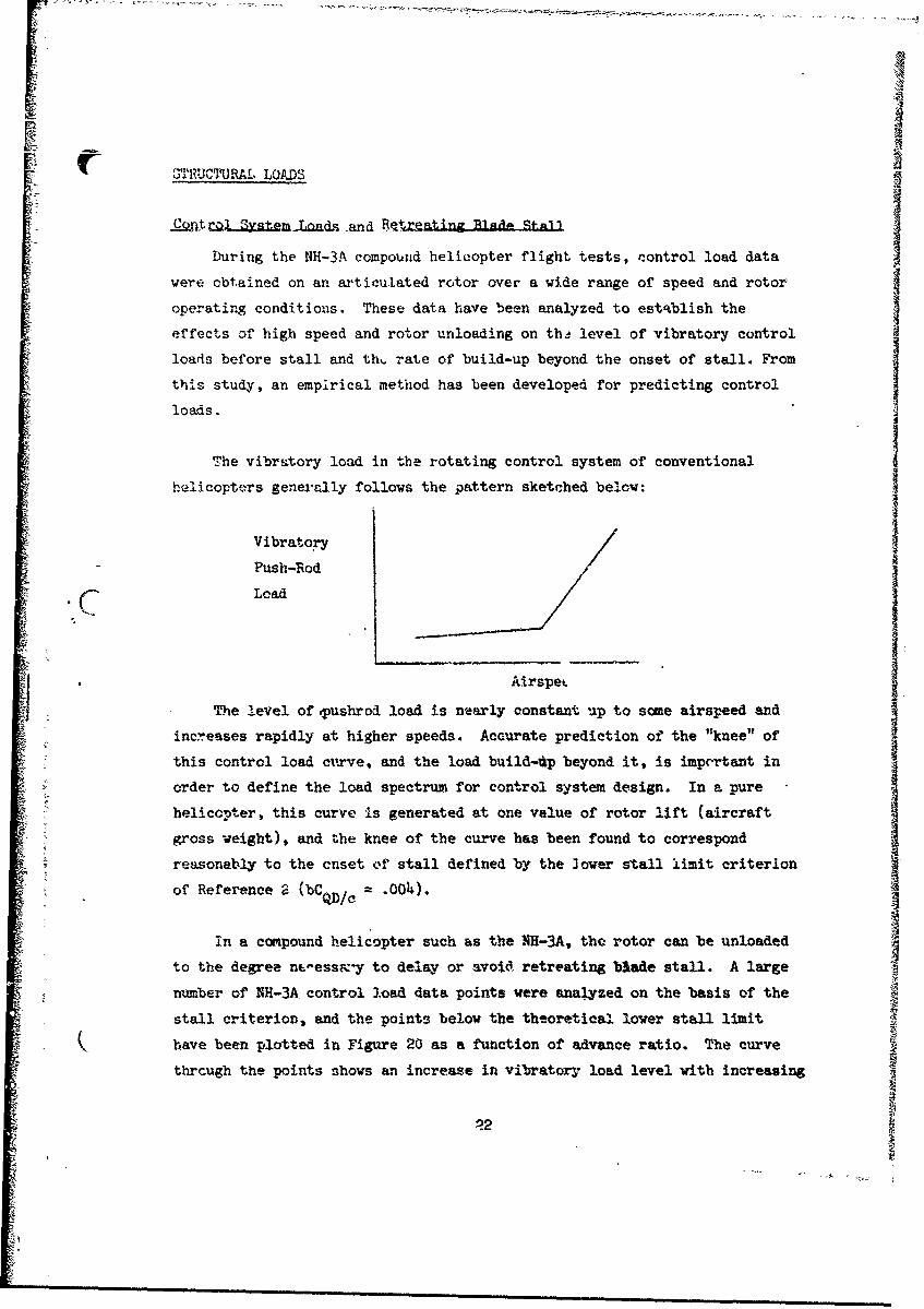
The vibritory load in the rotating control system of conventional
helicopters generally follows the pattern sketched below:
Vibratory
Push-Rod
Load
Airspet
The level of Tushrod load is nearly constant up to some airspeed and
increases rapidly at higher speeds. Accurate prediction of the "knee" of
this control load cirve, and the load build-Up beyond it, is imprrtant in
order to define the load spectrum for control system design. In a pure
helicopter, this curve is generated at one value of rotor lift (aircraftI
Sgross weight), and the knee of the curve has been found to correspond
reasonably to the onset of stall defined by the lower stall limit criterion
of Reference 2 (bCo)/c, .o0).
In a compound helicopter such as the NH-3A, the rotor can be unloaded
to the degree nvessmy to delay or avoid retreating blade stall. A large
number of NH-3A control load data points were analyzed on the basis of the
stall criterion, and the points below the theoretical lower stall limit
have been plotted in Figure 20 as a function of advance ratio. The curve
through the points shows an increase in vibratory load level with increasing
-?2
advance ratio. The Point- rpesent a vid rarne of unstailed rotor lift
akni propulsive force conditions, demonstrating the basic influence of
advance ratio upon vibratory control loads.
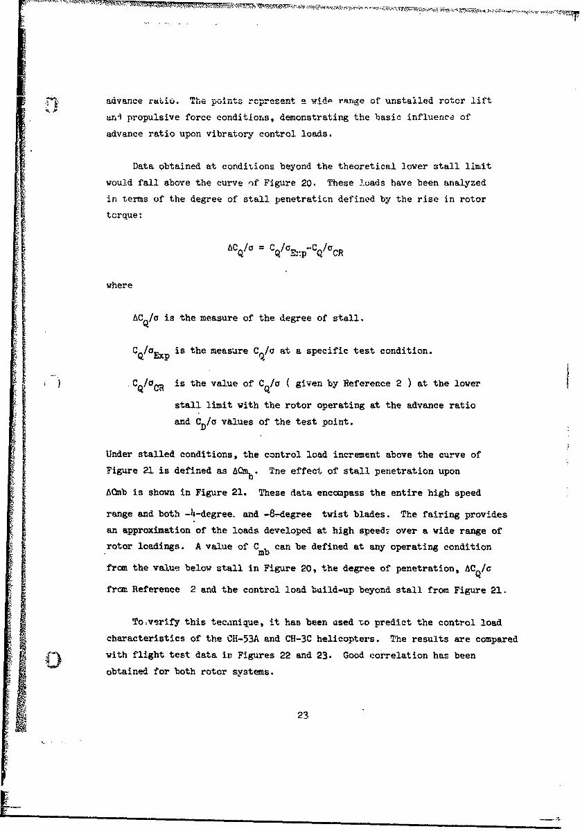
Data obtained at conditions beyond the theoretical lower stall limit
would fall above the curve of Figure 20. These loads have been analyzed
in terms of the degree of stall penetration defined by the rise in rotor
torque:
ACQ/a = CQ/E':pC Q /CR
where
AC Q/a is the measure of the degree of stall.
CQ/OFZp is the measure C./a at a specific test condition.
-C /a C is the value of C Q/a ( given by Reference 2 ) at the lower
stall limit with the rotor operating at the advance ratio
and CD/o values of the test point.
Under stalled conditions, the control load increment above the curve of
Figure 21 is defined as ACmb. Tne effect of stall penetration upon
ACmb is shown in Figure 21. These data encompass the entire high speed
range and both - 4-degree. and -8-degree twist blades. The fairing provides
an approximation of the loads developed at high speedz over a wide range of
rotor loadings. A value of Cb can be defined at any operating condition
from the value below stall in Figure 20, the degree of penetration, ACQ/C
from Reference 2 and the control load build-up beyond stall from Figure 21.
To-verify this tecanique, it has been used T.o predict the control load
characteristics of the CH-53A and CH-3C helicopters. The results are compared
with flight test data in Figures 22 and 23. Good correlation has been
obtained for both rotor systems.
23

i- cz ' technique. when applied to the NH1-3A r otor operating envelope,
gives a set of control load contours which correspond to the test data. A
sample envelope at 175 knots (equivalent to the envelope in Figure 15c is
presented in Figure 24, which shows the effects of rotor lift and drag on
the control loads. Below the - 465 lb contour, equivalent to the lower
stall limit, the loads are nearly constant. The bigher contours indicate
the load build-up as stall is penetrated. It is apparent that rotor
lift level, and, to a lesser extent, the rotor drag have a stroi.. afluence
on control loads when the rotor is operating beyond the theoretical lowerstall limit. It should be noted that these loads correspond only to steady
level flight. zaring most man-uvers, with the rotor out of equilibrium,
control load levels are substantially lower than the values that would be
predicted, extrapolating from steady-state values.
A limitation encountered with the five-bladed rotor system was the
high vibrator? load,_ in the rotating scissors link of the main rotor control
system. Loads above the endurance limit were encountered when operating at
high forward speeds and high collective pitch settings. Rotating scissors
"loads obtained with the compound coniiguration and five-bladed rotor system
are shown in Figure 25. The loads increased rapidly with airspeed when
trimmed at the maximum 135 knot collective trim setting. This increase
closely parallels the build-up of push-rod loads and was apparently due toblade stall. With the wing removed greater rotating scissors loads wereobtained at an equl. lent collective pitch setting since the rotor was more
heavily loaded.
With the six-bladed rotor configuration increased loads on the rotating
scissors were anticipated, and provisions were made for the installation of
dual rotating scissors. Due to the load sharing between the two scissors,
vibratory stresses were reduced to low levels for all flight conditions. The
stationary scissors, however, which indicated lower loads with the five-bladed
coifiguration showed a substantial increase in vibratory load for the six-
bladed rotor system. This increase in load was noted both vth and without
auxiliary Jet thrust and became a limiting factor when operating with high
Q collective pitc< at high forward speed. Figure 26 shows that load levels
exceed the endurance limit of the scissors at high forward speeds with the 120

- _ knots collective Pitch setting. The approximate boundary imposed by these
loads was shown in Figure 151. Since this'limit did not seve.rc.y restrict
the flight envelope, no modifications were considered nec-ssary.
Blade Stress
The effect of rotor Lift and dr-Z upon blade stress characteristics
was investigated over a wide range of airspeeds. In addition, msain rotor
bladu twist and number of blades were vzried to evaluate the effects of
these parameters upon blade stress. Recent emphasis on high speed rotor
operation has made reduction of blade stress particularly important, because
stress, rather than power, may determine maximum allowable flight speeds.
In an articulated rotor, the maximum blade vibratory stress usually
occurs at the bottom rear corner of the spar at 60 to 70 percent span
(gage BR-7 for the NH-3A). Figure 27 is a composite plot showing the
effect of wings and auxiliary propulsion on blade stress of the five
blade, -4 degree twist rotor. The bands represent stress data from numerous
flights over a range of rotor operating conditions. The band is widest for
the full compound configurations due to the increased size of the available
flight envelope.
Without wings or jet engines, the vibratory stress level approached
6,000 psi at 140 knots (CAS). The addition of auxiliary propulsion to
the pure helicopter reduced the rate of stress ini'rease with airspeed -
apparently because of rotor unloading produced by the jet engine-sponson
assembly which developed considerable lift at high speeds. The greatest
stress reduction was obtained with the full compound configuration in
which the addition of the wing permitted significant unloading of the rotor.
The effects of rotor li•' zd airspeed upon vibratory stress of the
-4I degree twist blades are shown in Figure 28. Forty-six data points
were examined for speeds between 149 and 194 knots, rotor lift values of
4,300 to 16,000 lbs., and rotor drag of 900 to -800 lbs. For this range
of data, stress was determined to be a nearly linear function of speed
and rotor lift, but nct significantly affected by rotor drag. Consequently,
25

stress is seen to inorease, linaarly, with forward speed at a given lift
value and to be strongly afected by the degree Of unlouding. This stress
reducing effect of decreased rotor loading was shown in Figure 27 by the
3ow stre.-es demonstrated in the compound configuration.
The insensitivity of blade stress level to rotor drag is not unexpected
for the -h degree tvist blades. In full-scale wind tunnel tests of the
H-34 (Sikorsky S-58) rotor system, Reference 3, stress was found to increase
in zero degree twist blades with increased rotor propulsion, while -8 degree
twist blades developed reduced stresses as rotor propulsion increased.
Therefore, it may be concluded that -4 degree twist blades are relatively
insensitive to rotor propulsive 'orce.
The effects of number of blades and blac •wist were also evaluated.
Figure 29 shows that main rotor blade stress was lower with the six-bladed
rotor than with the five-bladed rotor having identical blades as expected,
because of the lower lift required per blade. The increase in twist from
-4 degrees to -8 degrees shifted the location of maximum stress inboard
C (from BR-7 at 70 percent span to BR- at 60 percent span) and increased
the maximum stress value. These data were measured with collective pitch at
the 80 knot position which, at speeds above approximately 120 knots,
resulted in the rotor operating at a drag condition. The increased stress
measured on the higher twist rotor under such conditions is in agreement
with the H-34 full scale wind tunnel test results discussed above.
Effects of Rudder Deflection on Tail Rotor Stresses
The effect of rudder deflection on tail rotor blade stress was evaluated
as a function of airspeed. Figure 33. shows NB-R vibratory stress versus
airspeed for 0, 10, and 20 degrees left rudder deflection. As speed increases,
the effect of the rudder increases, and the tail rotor thrust requirement is
reduced. Lower blade coning and flapping and, therefore, lower stresses on
the semi-articulated rotor result. During the flight, main rotor power was
reduced slightly between 0 and 10 degrees rudder settings. The data indicate,
however, thet a stress reduction of as much as 25-30 percent can be achieved
at constant power. Camber or positive incidence on an adequately sized
vertical tail should have the same effect.
26

SAIRFRAME VIBRAT I 'ON.Prior to flight testing, the NH-3A was shake tested with cad without
wings. These tests, described in detail in Reference 6, indicated That
the NH-3A vibration levels with a five-bladed rotor would be lower than
other S-61 series aircraft (SH-3A and CH-3C), primarily because the NH-3A
fuselage modes are further removed from 5 per rev. The response of the
NH-3A with the six-bladed rotor was predicted to be even lower due to the
lower rotor blade loads and the absence of fuselage resonances near 6 per
rev operating speeds.
Flight tests confirmed that NH-3A cockpit vibration levels were in
agreement with values predicted by analysis of shake test results. The
effects of number of blades, blade twist, wings, and jet thrust on vibra-
tion are discussed in the following paragraphs.
Effect of Number of Blades
Cockpit vibration levels of the five bladed and six-bladed configura-
tions are compared in Figure 32 for a range of flight conditions. With the
.-4 degree twist blades, the six-bladed system reduced both vertical and
lateral response. With the higher twist (-8 degrees) blades, the six-bladed
system provided little reduction in verticaJ response, but lateral accelera-
tions were reduced by 50 percent.
There are several reasons for the substantial improvement with the
six-bladed rotor. First, blade airloads generally decrease with higher
input harmonics. In addition, the blade response characteristics are such
that the six-bladed rotor transmits less of the applied loads to the
fuselage. The natural frequency of the second flatwise bending mode of the
S-61 blade is near 5 per rev. Blade response at this frequency providesconsiderable fuselage vertical excitation in the five-bladed rotor, but does
not feed through the rotor head in the six-bladed system.
Similarly, lateral and longitudinal fuselage excitations result from
n-i and n+! edgewise blade response. Since the S-61 blades have a fV rst
edgewise resonance near 4 per rev , the five-bladed rotor passes hi-h 5
27

Der rev later-• and long: tudinal loads to the fuselage. With the six-bladed
rotor, the 4 per rev response is not transmitted through to the airframe.
Finally, Figure 33 shows that two of the three important modes of the
NH-3A fuselage response are less sensitive at 6 per 'ev than at 5 per rev.
The higher vertical response to longitudinal excitation at 6 per rev may
explain the lack of difference in vertical vibration between the five- and
six-bladed rotors with the -8 degree twist blades.
Effects of Blade Twist
Flight test results on -4 degree and -8 degree twist blades, also com-
Dared in Figure 32, indicate small changes in cockpit vertical vibration
levels. Howev r, the cockpit lateral. levels, especially with the five-bladed
configuration, are significantly higher for -8 degree twist.
Transmission Support Structure Stresses
The transmission support fittings transmit loads from the rotor system
to the airframe. Conseq;•.ntly, stresses in this area are affected by the
same parameters which influence airframe vibration. Transmission support
fitting stresses are presented in Figure 34 which shows that the stress
levels with the six-bladed rotor were only a fraction of those with the
five-bladed configuration, especially at higher speeds. This behavior
parallels the cockpit lateral vibration characteristics shown in Figure 32.
Rotor Unloading
Figure 35 shows the effect of rctor unloading upon cockpit vibration.
The use of wings and auxiliary propulsion resulted in reduced cockpit
vibration at high speeds, primarily because of the delay or elimination of
"retreating blade stall. Analysis predicted vibration levels at 180 knots
in the compound configuration to be equivalent to those at 140 knots with
the rotor carrying the full aircraft weight. The predictions were based
on ne assrumption that vibration levels would be equal at the onset cf
stall in the two cases. The stall criterion of Reference 2 was utilized.
Fig'ure 35 confirms that this is a useful method for predicting the effect
o0' compounding upon vibration levels.
2
28

Tail Shake
Commencing with testing of the six-bladed rotcr confiu-.,ratio•, alateral tail shake was encountered. The tail shake was defined as a low
frequency, high displacement, lateral oscillation of the tail assembly,
believed to result, from turbulent airflow generated by the main rotor
impacting on the tail pylon area. Although the structural integrity of
the aircraft was not seriously affected, the vibration level increased
with speed and became objectionable at high forward speeds.
In an attempot to reduce the tail shake vibration level several
possible solutions were considered. Previou• testing with the five-bladed
rotor system had been accomplished using a main rotor head "beanie"
fairing to streamline the airflow from the main rotor and deflect it down-
ward away from the tail rotor. As an initial step this fairing was
modified and Installed on the aircraft. However, due to the damper instal-
lation, the fairing was installed approximately seven inches higher on the
six-bladed rotor system than the original installation. Since the effec-
tiveness of the fairing is a function of several factors including its
U diameter, thickness and distance above the rotor head, no significant
reduction in the tail shake was accomplished. As an additional modification
a skirt was installed around the circumference of the fairing to effectively
lower the installation. Subsequent flights revealed that only a small
reduction in the tail shake could be accomplished with this configuration.
- Simulteaeously, the effect of fuselage trim attitude on the tail
shake problem was investigated in an attempt to remove the tail. pylon from
the turbulent airflow. A c.g. change to 265.7 inches or san elevator setting
of + 4 degrees was found sufficient to eliminate the tail shake problem.
The latter solution was used for the remainder of the six-bladed flights.
It is apparent that to avoid tail shake in a high speed helicopter or
compound, the tur-ulent wake of the rotor head/pylon should be reduced as
much as possible, and that, further, the tail rotor and tail surfaces should
be located outside the rotor head wake if at all possible.
02
*29
iiThe NH-3A compound helicopter was designed to provide a stab!- aircra't
for research and data acquisition purposes. To accomplish this the airframe
was equipped with a large empennage. The result of this design was a stable
aircraft, even without AFCS (which had been removed), and there was nounexpected loss of stability with speed. Flying qutlities were generally as
expected, and the influences of wing, jets, control surfaces and the
different rotor configurations were predictable.
V-N Envelopes
Although the full load factor capability of the NH-3A was not developed
during this program, sufficient load factors were generated to indicate themaneuver potential of the aircraft. Load factors achieved with the jet
augmented, five-bladed configuration are shown in Figure 36a. A maximum
of 1. 8 2g was obtained in a left turn at 120 knots indicated airspeed. The
minimum load factor of .05g was obtained during an entry to autorotation
at. 120 knots. Addition of the ,zing expanded the envelope to a maximum loadfactor of 2.24g, shown in Figure 36 b. This was obtained in a climbingturn at 160 knots. The addition of a sixth main rotor blade (without the
wing) also improved the load factor capability of the basic aircraft.
Figure 36c shows that a maximum of 2.2g was obtained at 120 knots. This
configuration achieved an indicated airspeed of 230 knots in a dive.
Theoretical Correlation With Flight Test
Flight test values of control positions and aircraft attitude agreed
well with theoretical predictions based on small scale wind tunnel tests.
F: ire 37 compares flight test data at 125 knots with predicted lateral
directional characteristics from Reference 7. The effect of the differen-
tial wing lift is apparent in the lateral cyclic stick data. This effect
was not considered in the preflight calculations and consequently near
zero sideslip there was approximately 1½ degrees more left cyclic pttch
than predicted. This difference had no adverse effect on the NH-3A, but
it should be considered in the design of future compound aircraft.
30

At speeds below 150 knots aircraft attitude aid control positions
were predinted using a digital computer program based on linearized rotor
aercdynamic theory. Figure 38 demonstrates the adequacy of this approach.
For higher speeds a combined analog-digital ("hybrid") computer was used
to obtain trim solutions. The hybrid computer program includes the aero-
dynamic analysis of the generalized rctor performance (GRP) program
(Ref. 2) which considers the effects of Mach number and reverse flow, and
has no small angle assumptions.
Figure 38 compares flight test with computed values of vnrious para-
meters. In calculating these parameters on the hybrid computer, jet thrust,
roll attitude, and collective pitch were specified as equal to the measured
values. Discrepancies in the generally good correlation appear in longi-
tudinal cyclic pitch, aircraft pitch attitude, and tail rotor pitch, at
high speeds. There was considerable scatter in flight test values of the
first two parameters, which could account for the differences. The dis-
crepancy in tail rotor pitch at high speeds is probably due to a high pre-
diction of main rotor torque and use of too lo.. a lift curve slope in the
• ) linearized analysis of the tail rotor.
Effect of Various Parameters on Aircraft Attitude and Control Positions
Effect of Drag Reduction
The effect of drag reduction on control positions, aircraft attitude,
and jet thrust is shown in Figure 39. There wras a signif~cant forward
shift in longitudinal stick position and an increase in flapping which
would produce anose-down pitching moment. kt 199 knots, two degrees of
downward elevator displacement were required to produce an equivalent
moment and return the stick to the position established prior to the drag
reduction modifications. This shift in longitudinal characteristics is
believed to be due to increased effectiveness of the horizontal stabilizer
resulting from improved airflow characteristics over the wing root and
landing gear fairing. A study of horizontal tail loading, determined from
stabilizer bending moment measurements, (Figure 40) confirms that increased
tail loads are the cause of the trim change. It was demonstrated, therefore,
0 that improved stability is provided by putting the tail surfaces in a clean
environment.
31

&' : . . •' ' -h , W.1•
*I!-"- A coxr.:-otd conflguraticn included a high wing with a constant
~LK.Jence �ngle of zero degrees (a':foil reference chord lin,•). The wing
aerodynanic centor was lo.2atcd near to the basir aircraft c.g. in order to
•etý-p thi wing-fuselage pitching moment ,!hanges cauised by changes in wing
l":t to a minimum. Therefore the aircrafv. trim and dynamic response
cht.racteristicF; were not expected to change significantly with the addition
of the wing.
, igure hi shows the effect of wings on flight characteristics of the
Nli 3A. For all flights shown in this figure the aircraft was trimmed at
80 knots with jet thrust at idle. The collective remained fixed and jet
thrust was increased to achieve higher speeds. In the full compound
configuration, the wing was developing a positive lift at 80 knots, so less
co'!ectije pitch was required than in the wingless cir.fi,¢uration. The
differential wing lift effect cui be observed in these data. The differen-
tia' lateral 'tick displacement required to counteract the positive rolling
mement is apprcximately 18 percent at 180 knots.
Dynamic response to a longitudinal stick pulse was measured in flight
with and without the wing. The results of a ½ inch longitudinal cyclic
pull and return are shown in Figure 42. These data show little change in
response due to the presence of the wing. The small d.fferences may reflect
the difference in actual control input during the maneuver. The measured
response is compared with calculated values in Figure 43. The measured
c-ntrol input has been utilized in the analysis, and tie results show good
agreement both with and without the wing.
Although lateral characteristics were not directly investipated, pilots
rport that, with the wing, roll control power was somewhat diminished, blt.
that lateral stability was improved.
Solidity Effect
To dete:.'mine the effect of solidity, the NH-)A was flown witih both a
32
S~32
rive-bladed and a six-bladed rotor system. Tnhe added blade inereases rotor
13. -4 _& a" " av~ iinoc thcp nAI n i-upyi tph rpn ni rpmnpnt nt. Ai
given speed and angle of attack. Figure 414 is a comparison of aircraft
attitudes and control positioni for the five-bladed and six-bladed config-
urations. The added profile power of the sixth blade increased rotor torque
at low speed so that more left pedal was required for trim.
Theoretical and experimental longitudinal response to a pull and ret'urn
were compared for the five-bladed rotor in Figure 143. A similar comparison
for the six-bladed rotor appears in Figure 45. Again the agreement isI! excellent for the first 10 seconds. Beyond that point, the matching of
control inputs in the calculation was stopped.
Effect of Twist
Main rotor blades of both -h and -8 degrees were test~ed on the five-
and six-bladed rotors during the test program. The twist variation caused
no changes in air-raft trim, control positions and stability, within the
accuiracy of the test data.
Effect of Horizontal Tail
The NH-3A horizontal stabilizer was designed to provide a stablepitching moment (Via lope, includi•ng the contribution of the rotor. With
the tail initially s .eL on this oasis, wind tunnel tests revealed a
serious reduction of tail effectiveness ove" a narrow range of ang.e of
attack where the tip vortices from the J-60 installation impinged upoi
the stabilizer. To eliminate this problem the span of the stabilizer was
increased to p-vide area outboard of the jet engines. The characte, lstics
of the NH-3A and standard SH-3A stabilizers are as follows.
SP-3A NH-3A
Total Area 20 feet 2 76.2 feet 2
Aspect Ratio 1.8 5.25
Incidence 0 degrees Ground Adjustable-5, 0, 5 degrees
33

The -ffect nf," 'h.± .n,.!reased stabilizer area upon dynamic response is
shown in Figure 14( for an aft stick pulse. The stick displacement was held
i'or the N1I-3A lon'eer than that for the SH-3A but with less amplitude,
g'ving a similar impulse. The maximum change in pitch attitude of the
NH-3A was only 6 degrees, compared co 20 degrees for the SH-3A. In addition,
changes in speed and vertical acceleration were smaller for the NH-3A.
Some problems were encountered with the larger empennage in hover
sideward and rearward flight. Pitch oscillations occurred in hover due
to intermittent partial immersion of the horizontal tail in the main rotor
downwash. This effect did not -ccur in calm air. The aircraft also had
reduced speed capabilities in sideward and rearward flight due to abnormal
airflows caused by the larger vertical and horizontal tails.
Effects of Elevator Deflection
The effectiveness of the large elevator is demonstrated in Figure 47,
which shows the effects of changes in elevator setting upon steady state
flight parameters. Figure 47a shows that a 2 degree negative (up) elevator
increment produced a much more nose-up attitude. This resulted in a
reduction cf the rotor lift requirement at constant collective pitch. The
co•bination of increased pitch attitude and increased rotor propulsive
force resul ed in a large forward stick motion and greatly increased flap-
ping, limiting speed to 140 knots.
The effect of a positive (downward) elevator deflection is shown
separately in Figure 47b. A 2 degree positive increment produced a
nose-down moment, allowing the longitudinal stick to move aft to produce
the required balancing morent. With the favorable stick position and
reduced flapping, speed :tas limited only by available jet thrust.
Effect of Rudder Deflection (SR)
The effect of rudder deflection on the compound helicopter flight
parameters is shown in Figure 48. Deflection values of -10 and -20 degrees
(left deflection) were chosen to counteract main rotor orque and provide
tail rotor unloading. Rudder defiecti i did not signif'-.antly affect any
flight parameters except rudder pedal.
f~314

CONCLUSIONS
1, The NH-3A test program demonstrated that the fully
articulated rotor system is well adapted to the
environment of compound helicopter flight -z speeds
up to at least. 230 knots, the maximum attained in
this program.
2. Available methods of analysis of oerform%.:•ee, stability,
control requirements, blade stresses, a:d vibration can
generally be applied up to at least 200 knots without
significant loss of accuracy.
3. Anticipated results which were confirmed by test
included the following:
a. Speeds in excess of 200 knots were achieved both with
and v' Thout a wing through application of auxiliary
propuision.
b. Blade stresses at high speed were acceptable and were
reduced by rotor unloading and by reduced blade twist.
c. Vibration levels at high speed were very acceptable
and were markedly reduced with the six-bladed rotor.
d. Inherent aircraft stability without any type of arti-
ficial stabilization was provided by an adequately
sized fixed horizontal stabilizer.
e. Blade stall and the associated buil'- up of control
loads was delayed by rotor unloading and by use of
increased blade twist.
f. Tail rotor blade stresses at high speeds may be signi-
ficantly reduced by providing anti-toraue f'rceb with
a vertical tail.
35

RECOWENDAT•' IONS
The folowiný areas are recommended for further study, based on the
results of this investigation.
1. The NH-3 4 research helicopter should be modified to permit
testing to higher speeds. Modifications required to achieve
speeds above 250 knots include the following:
i. installation of integrated controls to augment the
rotor when it is slowed and unloaded.*
b. Reduction of airframe parasite drag by fairing of
rotorhead, installation of new T-58 inlets and stream-
lining of aircraft nose, cockpit canopy and T-58 engine
housing.
c. Installation of increased thrust jet engines.
2. Serious study should be made of application of the 200-250
knot articulated rotor compound helicopter to operational
missions.
3. Study should be made of application of the six-bladed rotor
to the F-3 family of aircraft as a result of the very
favorable pilot reaction to the flight characteristics of
that configuration.
4. Further ý,.dy, including fli&.t tests should be conducted to
verify the findings of the tip spread analysis. Acquisition
of two-dimensional airfoil pitching moment characteristics
at Mach numbers from 0.7 to 1.0 is also desirable.
SThis has been accomplished at ftill rotor speed under U. S. Navy Contract
( i 000!9-67-C-0513.
36

1. Lock, G. 1. H., The Application of Goldstein's Theory to
the Practical Design of Airscrews, British ARC R&4 No. 1377,
1931.
2. Tanner, W. H., Charts for Estimating Rotary Wing Performance
in Hover and at High Forward Speeds, NASA CR-!IS, Sikorsky
Engineering Report SER-50379, November 196h.
3. Paglino, V. M. and Logan. A. H., An Experimental Study of
the Performance and Structural Loads of a Full-Scale Rotor
at Extreme Operating Conditions, Sikorsky Engineering Report
SER-50505, March 1968.
4. Bain, L. J. and Landgrebe, A. J., Investigation of Compound
Helicopter Aerodynamic Interference Effects, USAAVLABS
"Technical Report 67-44, Sikorsky Engineering Report SER-50474,
November 1967.
5. Paul, William F., A Self Excited Rotor Blade Oscillation at
High Subsonic Mach Numbers, Paper presented at AHS 24th Annual
National Forum, Washington, D. C., May 8-10, 1968.
6. Winter, W., NH-3A Ground Vibration Test Report, Sikorsky
Engineering Report,SER-611l00, April 9, 1965.
7. D'Ostilio, P. J., Jenney, D. S. and Segel, R. M., Flight Test
Planning Report, Sikorsky Engineering Report SER-611065,
January 21, 1965.
37

Oscil. 2 ' x xX x x x x x x
os .Ixx xx x xx x x N x x
4) 4=). 0 - t , U N
+ 0+-) L\rl C -U )U* t - ý U)- 0 HPo 1 Lrl UN 1- --: U\~ 00W Z
rqH0 H 4rD0~ -' Cd r-4 1 .4 0CJU4L U. ý0 0P *4$~ 1101 0 E-P 0; 1.H + 0 1
-,~.4 -)- 1I 4-1 XH .0 II w ,- ~to0 .1t-- E ýc bO 43 -) 4) 0
HO 0V4 +30Wk.P H0H-> 0 0M 0 0 0+3 -4 >~ > - 4 1 ^
V. NH U4.)r4 -14t (H EE4- -3 0M w 2.N)I C\> V) 4-'M ~ 0 4)0- t4' i4.1000 4'r1 V, $4 H 4 ,-11 0 0
m L + -.0 $..> &-fO t0 0) 9: !4 0 0 V- 4E-4H)U" f V 4- N ) HH 0- 4- 0j P 0 V AM > *-i M d 11 4 IL. -%
g r+)- g. C, g I I ,0 1 4.r4.. -1t~4 -H I L -Awt~ ~.
0 9 . CC)f) r-40 0II 0 P4 4 0 0H$4 -4. 1.4 1$.4H. .X H- H r.^ IHH. d
0~~~~ ~ ~ C 00 -IdC Ua -rj ~ ~~ ~ ~ 0D 00 :4 r,ý% t
4+1 -H t4 vro 0 0 5 > -- r ý k 4 - -4 W I -i - *I ý-i "
Ej -4 to: 04D . 1 ~-3 00ti 04r - - - .rIrI0 r
H 1 m- t H rI 0 IL II
HO 0 IV > I I 0t I- 0 0 0 0 00q
00
0b~ 0 0 000U~t 0I 0 0 0 00J0 0f 0 0-H 0 H H0 H 0 0- HH
0 '0 0~ 0- rI CM0 0 0flCM CMl m' .M t m M. COm M~ mm cn m mC'
-1-
4 0 0 0 0 0 CM fl 0 0
ILIH NCM C CO
C38
/ o 0 0 0

X Oscil. 2
Oscil.l 1
P/P Tb1 l
4- 4) 4-:OU) UN, 4-' U) I I J--'
$4 0 'J 0 ' ,-4
0 HO I) .-4 H~ 0) =0H * )
~~~ a) V$4 zC ItH . C U~ +
H> 0) + +4 Hr.- U col E
o~~r to0 ' 4--l~* '
o c: 0 10 1~ (y\ ) T0 ~ 4.d. *,-4 (1 H . YH
4-)4) rH Hi 4~-) 03 od itCV
0~ 4> 4? U-P w4 Hd a:0 -14u2
C0.d~f-O 4U) > )O) 0>-H X
cs 4))41 4
INHC) bo - (Yfl) ) 0 W 0>0 xC -
.,A' co.im0 o0- 0B II $L\)'~ 4- t$) 4-4 )dE04
r* A *-4 ': 0 0 11d 4. E~ ::H V *
4-)4-11 0 z r-4 0 I 4 --l En 0 4 -) 4 )to 4 0 0) ) -
r. Cr\ (D 0 H4 0t' r .-I 0 0 X
4)-40 4) Hd HId H4 ' H H C ~ N r.4' O H nto~ 0 N ý n -f r 0 E i -
41 0 0 0 0.>0 4I 08 H80 0 0 -0 0) 0 - 0
0 H HO >0 0- 0 0 0 0
0 a ; fC, 4C ) 0 0 -1 W 4 C 3 0 o~ ~
4) ) 1-i -* E 4 .4 V -4 -- .. E .
4) U) 0d 0D 0iA14 4)-l4 d( 4
0 ,Dj 0 0n b 0 0o 0 0- 0 0 0 0 0
-r 0H 0 + 0 E- 0C~
a- -0 0 -r ý
rj + +) CH I +4 + +~ +s c
Hto 4 > + t
(n - -,4 - r. 0 0 .Cd -) 4) 0 4
+ 11~ 0.' 0- 4 - 1A \ X 0 0 HN H- - -1o -)> .0 H- H4 H H 4 toH
Ir > I- it 4, fI ri , I
44 H P4 0' 0'4 H H40$
'0 ý -1:4r 0 H4 as m' a.) r4 ( - J to. t
C '! a )! W' W 4 - )

S. x
x N xOscil. 1
wH
* ~~0 0df *-o Fi ~ C-40 r- a' * 4-) S co *.,4 &1-;.. a)r-1 If H4 (d I'l t- 1 OH E-4~ H4 ri .I- E-4 IE-' I W~ coo rqO E- 0
HUH H1 it's 0 H0 14 .-1 i a Cut
0' +' V-1 VCO's 0 . -IHG
U Qr CO 0 U0 C; 0u %so H .43zN~ >~I 4.) 4- >C it l 0 tI c
II ~0. IV > 0 te- IO * IO H N o 0
4.) 4-) 1 H( M U) wO 4-) E! 43 F1Cd.-H 0U0C) E!e 00 > 4) H-H +) 43O0 0 N I0>~ >El4 :: 1c 0
4-)j > Hw . .0 0 o 0 0co~ S3 :
0-~ 0 ~ *,-r4 9 4 'oX t 0 FOe-• 0 Hci 0 OC'~O. O- x 0E-4 0 0 ~C\ N r. >cq HO 0 E-4
0 0 0 H HO 04. C) CoC) H 't rH H OH 00 -N 0\ 0 0i 0 C * H >.,j tor4 i S i riC) cdC U) 0 -rq n ) a$ t o.,4\H .L 43 4 H -1%4L b-jr +)H
Cd C00)U E4r.C~ Cn 3 4-11 4.) 4 -14-' +) 0 - )+4)414-)+ 0 .4-''d u.P-P 4-ý Cd 4-' P
0 5 0 1\C l'D o il o.-to 0 4.o I
HCq HH ,-IHI Hqrq H *HH -4 H H ' -IO'bý rI H HCI o 0 C2t
0- 11 to 111 C 1 co *-r4 0 co 0 0( GU) H-4 COHH H- HH- H H- H :3 H V wH r- H 0dH
0 ~ ~~~~ 000 4)>4>0 C >0> >-
000 0 0000 1-i 0 0 0 0
Co 00 0 :0 00 0 D0 30 0
Cd H0 0 0 00 HL
Ho H H-~ E0
S:I + +: I4 C to qu VC;CO 00 08 + 4
~~o ~ r sOuCJ
Hl~ 0u Ht CuC H CuCtCf
H- 0H HM Hý C Cuj \ CujCu~ C Cu C
H0 p-CO - -I cu co H Cu 04 u
Cd N- - ý1 I -ý 1 1-

N 4 x 1.4 xOscil. 2
oscil. 1
0 Cd 1t;
) OE-4 C0 E-iS 0 Ui,% (D 1:; 10cn% t 4-0 +$-4 4)000 -P > r- t--H H H H 0 9:0 ON f to- m0\ O
+) 94 H 0 .4 HII 0 Il 0' )10 1 ~ to * UH-
z3 z .,I U) It H~ -I010% CC-)Cj+) ;
r.- 9 P ~0 x 0 H CJ~>- C\j >' N0().a 0d.E CO a CM ON ~ 0 r0
o- 0 a> H0 00 r> i i Im4) 0 V.~ 0 Cd
*Oai 0 r. d CaS0 1
0 0 0 0r_ , H ri r4 4)4> H 0 0 0 =*j00
04 11 H ,qJ H ' WO4 0 0 H 0~ H 1 1 )I0 0 H% p r4 H 4. A443 H o H2 0 H~
r- xc H C 3l ., 0 H 0~S ý4 0~' *4. >,)
H~p r *ao n D ( t 0 r*i r:; H
*,-g E,ý~ *- f4 *r4 ~ *-,i (D J'd .- 4 *-;4 U2 ',4 Hm LF-aU HO H 43H. *dý H HCaS 4\4H H.4 00 H 4I3a~q 0 0 ~ 0 $ 4-> .
W 0 WW 0o .HHH 4H HI bC 0 CO Q) 0
) 0 0k 0 - $4 00 E 1 0 0 0 0I 0- ) -P ()1 0)r. 0 0 0 0\0 0 0 Qa)rI41Q:3) 0 Q.0Q4 d NZd 0 0)C
HI 0 0 0 0L 00 0 0 0 0 0 0
0 z 0 0 C 0 C)
0 0- 0 0 C 0 0 CI Y n mC)m C) Y Y V Y yc4-4
AI %.) 4- -
as A I I I I
C4+1 +
0W A44 q.J .4 +-t.4o
toI~ C\' ON~ ON. 0 0 0) 0 C0 0 0)
E-P410-aI I I I I I I I I I I I
H) (co ('40 t\ 0\ H (Y) C
.4. CY) (n-Z L A\tr UN lA\ LA \.0
\0 -- ON CM (nl _r ON,00' 0 H:1z ;?-1 t- t t o C co C) Co o' a.

xx
Oscil. 1
~x x X 4 x1P/P TbI.
WI 0 0
C,:~ LIN H -P4)~
>0\ ** 0 t
4. +) 0
"H I r.-
03 Ez ) ;> ~ %-k tr 14. a
>0 > _r a-%05~ C-1 4.)
4 -) 0 0 -T 0 - X 0 1 -0.- td0H d I 4-)3PI'D rl: :3: 14 4 O OC~~~~3 U)4 rJ .cuJ C O,
HD H
>~ . 01 0r Hi
+J 0 0 H.
(D I-) oi cr2 it'. '. - o0L ~ 0\ to Ho
Id 4) 4- El 0 1- 0 4> 0

Oscil. 1 x x x X x4 x xX
4 0 -Z0HHl
.r4 r.4 0
cl 0 CM r4C+0 -4 01
04- o 0) k 0r4 $-I r4 I. c
aS; C4('
.4-i~b +' H d .4-. Ci P 4-2 (D 4- 4 ) 4 4)
U2 co ., j r .. o r4)i r-4 4)4 "-4 -. $.d ,
-- 1 .4 I Ii 4 )
V4)
CI) 4)' 4.) -
.r4~~~~r *r-4 *r , p*d*4q*-4*4 'i0000H %0 Hr- \0 Hr0 --1 a
,41 'a fd a!4aS ~ 4 4)4 p'
H 00 0 S3 0
til 430
C4- U'i' 0'J\ H
'1 0
~4-)

C Oscil. 2
Osci1.l 1 X
414
$4 0
4. 0 I4-$4$43
01 0 V2
0 0 H0
2 0 $4
0 4
"-4 04 Lp~
4' 0 1,c1o'4 0 t 1Zco 1 9 1 4 1 0 .ý o
GA 10 1
I 4j Qa 0 H H
0 0l 0I
0 01 0.
a cu m cn 0 0 0
a ~ ~ ~~ -HI I 41 3 4 350 4' 0
I ~ I '~i '0 0 I'S 0 cn~a a 0 0 P
41 N 4
H Hn
wIlI C> 30 03
44a

TABLE I1
NH-3A PARASITE DRAG BREAKDOWN
V = 160 Knots
SH-3A Design Est. Present Est.
Fuselage 5.12 4.00 4.00
Main Rotor Head 9.92 8.90 8.95
Main Rotor Pylon & T-58 Installation 2.36 2.36 2.36
Vertical Stabilizer Plus Interference 0.37 0.82 0.82
Horizontral Stabilizer 0.25 0.59 0.81
Tail 4heel 0.46 o.46 0.46
Landing Gear Pods 6.95 2.67 3.20
Tail Rotor Head 1.76 1.76 1.76
- J-60 Nacelles -- 2.20 6.20
Wing installed 1.29 4.00 (°40
Flaps)
Protuberances, Gaps, Jcints and 2.75 0.51 1.54Miscellaneous
Mimentum Losses, Spillage Drag 1.17 0.40 0.90
31.11 25.96 35.00
Without Wing & Jets 31.1). 22.47 24.80
L 45

I•I
4.; i) I
NI
*,1
%SN4

vi
NOT REPRODUCIBLE
Mod
KA
fz
1 712
A4

MAIN ROTOR DATA
DIA{ 62'BLADES; 5 (6 BLADED CONFIAI~rFOI : MOO..').0ZDISC AREA: 3019 SQFT
(_
MAD AREAJ(EA). .9SF
.18.
-- " NOR-Z A IN A.MT -3 PIIq-- PrrýTCH VANEr,,1.N CNEW WHEEL AS PE .P
a •T : Y
,N_
• • • p•,, T.B.
RiK

36C .? -;-
DED~~~~..... .....NO...~4 ... ~ t
39.gsip ------- )--
EDS LENGIG. NOT6-6 SHOWN)__
QFT -CAT1O) SOA.2_O.7
STA~~W V6.445.3,5
:j06 LE[GT -7% Q
I~ S I A _ _ _ _ _ _ _ _ _ _ _ _ _ _ _ _ S T A . _ _ _
STA~~ ~~~~ ~~~~ WL 191.5.i.1 -WEE AS 1.53-7sWL 11.65 PLATTIRERADIUWMNO

_ 1.d-O
AIF - 2*Ir
-i-.A TAI ROTR
243~ STABIL ORIZAER DATA- OOIA 9- CEMS(16T- 37'A
iOLPViiY RATIO 5.25L JURFWA- MOD. MI
Ik 1:
C"-C CAR9O., C 20 5 TIS-AT A ZROO.
VETIAIL ROTRLDEATA
ETA MA (%A 44344SQF4 1 ?j JWOETRADLETIO(N: t288
WL*. AIFL;h . 09
* ,j 4 ' Fgr 3.3 N-3AHlcp ihJt
-A 718 - ~ -General Arrangement.
SW-3A TAIL WHIECL TAIL WHEEL OATA________&00_6 -TPE M
wA FLAT TIM, RADIUS- 4.6 4
4-A4

I'v
M
Nz§. -gSk:
AN 070
N ' ~ 643
1--
a5
NOT REPRODUCIBLE

06~. TEWPTY MOST -S
MAIN RO TOOIA:2ULA6ES: 3AIRFOIL : MDISC AREA:
WING SPAN SLADE AREA384 (r-u*)SOLIDITY RA
TWIST(LIO:AlR 660
>18&
7'a
N n AMEMCAN T-39 SAUPELINERTREDI2(IO.0)---j lCELLE HOUSING A P&W .160-P2

CONTRLS CLOE
T--
MAIN OTORDATAAIRCRAFT ADIA 2' _ O~D.5~OTA
gLDE: (6SLDD ONIG N~ ~o~ 1APRwA
AIRFOIL:~~~~~~h .............._ TL IP A26 COR
DIA: 660MA 6.
AIFI :T MO..42OLPP
PITST(H) : WMESA27.
WLIOG~QC CAINLO
LINER A-q
STA ~~ BACK TO BAS K BEN5(
STA 14.675 r WT H A REGESR .WL 19.95. . FLATTIRERADUS 600

- 'o 24STABILIZER DATAMODIFIED CESSN4A T-37A
FLAPPINGSPAN: 20W,FLAP DATA ASPECT RATIO:e 6.25
stof CHORD s31.3% WING CHORD AREA: - M SQFTCMOEI?5'/ .vr CHORD 25%C*Ac-
*0. DELCTO *34 WtCIQENCE. 3.5-tO* (?OSITIONJGROUNO ADJUST.)63 M~cdoELEVATOR DEFLECTION: ±I5Y.- 267
COR 8 10,
STA S4-3A TAIL ROTOR
_____ ____ ____ ____
_'GE
CAR lo6X
Jco TAIL-ROTGR SLADE DATALOCATION - ST;1 COGRTIDIAAt- 124 C10!- 4)
MC AREAs 83.9 SQVT
- 7' LADE AREA (EA) *7344 SQFTSM10iiir RATIO (~r;.183
K UIENDIX WL .AIRFOIL: 03D. .0012LIEG 233.5 FEAT"ERING AXIS: 2ZSZC
c;M- 1NT. GkA.R w~x 011A 124' TAC G2 I0.5 Twist ZERO
VERTICAL FIN DATAAREA: 44SQFT
cs STARUDDER AREA: a.6 SQFT
I RUDDER DEFLECTION: ±"2V
44C S. -iur 5. .-.. 3 Copon Helcote
-~ 715Gener-al Arrangement.
IN-41A TAIL WHE TAIL. VWEL DATA
513 00- i.30
STA VLTTI P ~DUS~ 50
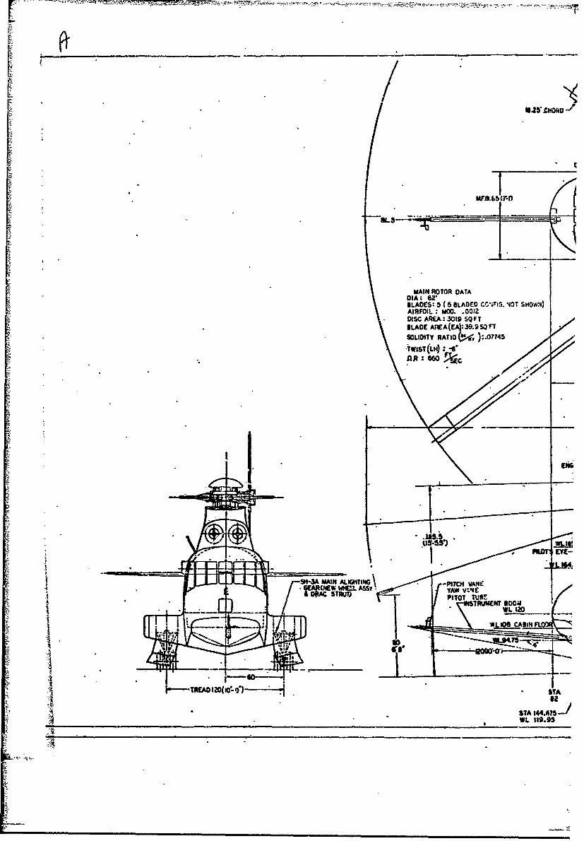
7 IFI O. .01SOLIITYRATI(! W? ).07745)
DAR: 02'F
CMSOLIDITSSYYRATW V )o4CSTTWIST(L14)TUBE
ILIZ
-,am12(l- ')STA 4 A J
SIM t319.93

CORIU LSCOE-
25%C
At* 2%Cu~c425(3S-3
-OVERALL LENGTH ?t?'.6---
ENGINES T53-GE-4(Z) WL17
1I 191 16j
rsurec - C-MC ITA. GHEEL
PE O.II .OO .TA .. T..J&19STA~0 114141,11
ZUR GRSSR 116 4
EYETTIERWJS60

40 (zoe-Cr
- - . ,,,-
24 STABILIZER OA.TAMO0IInED CESSNA T-,37A
FLAPPING SCAN: M;O0""SPECT RATIO• 5.25
2S%CuAC APFA * 6.3 SQ FT- INCIIENCE: +.*,-o" (2POSITION;GROU,4D ADJUST)
ELEVATOR OEFtECTION:' .I!ý-26'
STA S 3A TML ROTOR
__•_____.(PEAR 9O.A
TAIL ROTORILADE DATAD01A1- 124 (io'- 4"DISC AREA, 83.9 SQFT
SLADE AREA (EA) 7.344 SQ FT
SOLIDIiY RATIO (~) IqSS•WL AIFOIL*. MOD. .0012233.5 FEATHERING AXIS: 25ZIFL D.
C•-3C INT.&AR 220.5 TWIST: ZERO
TA686.2 18'- 4.5'
VERTICAL FIN DATA
AREA:, 44SQFT'RUDDER AREA; 8.6 SQFT
RUDDER .O-EFLECTION: -25"
/*15-
44 TA Figure 6. NH-3A Helicopter - General71..-- Arrangement.WL 7
!- 3A TIL WitEE TIAL WHEEL DATAT 000-6 TYPE M
00- 18.30" _71 RR- 7.1
STA FLAT TIW RADIUS 4-t 51

3200 .COLLECT1VE WA SET TO TRIM THE
AIRCRAFT AT THE SPEEDS LISTEDWHEN JET THRUST WAS SET FOR IDLE
2800 OFLT 20 JE£I INOPERATIVE, VARIABLE COLLECTIVEQFLT 20 120 KN COLLECTIVE,FLT 14 80 KN COLLECTIVE-FLT 16 COLLECTIVE 10% <8 0 KN VALUE[FLT IS COLLECTIVE 20% < 80 KN VALUE
2400 -- FLT 20 FULL LOW COLLECTIVEPOWER REQUIRED BOUNDARY, JETS INOPERATIVE
-------- POWER REQUM' )OUDARY, JETS OPERATIVE
W _ * I
eo " * 0%'i
it
1400 - I
-10 lo 0•
S.0 40. so 120 160 20 240
* !CALIBRATED AIRSPEED, KN
(a) W�IHOUT WINGS, WITH JET PODS, FIVE MAIN* ROTOR BLADES,-4I DEGREES TWIST, -15
DEGREES 6e' 5 DEGREES iTe HT
,FIGURE 7. NH-3A LEVEL FLIGHT ENVELOPE FOR VARIOUS AIRCR;2T. CONFIGURATIONS, ELEVATOR SETTINGS AND HORIZONTAL.STABILIZER INCIDENCES.
52

I *
3600 * TF tCOLLECTIVE WAS SET TO TRIM THEAIRCRAFT AT THE SPEEDS LISTEDWHEN JET THRUST WAS SZT FOR IDLE
3200 0) FLT 75 JETS INOPERATIVE, VARIABLE COLLECTIVEG FLT 76 120 KN COLLECTIVE
FLT 73 100 KN COLLECTIVEFLT TI 80 KN-COLLECTIVEFLT 75 COLLECTIVE 9% < 80 KN VALUE
2800 0 FLT 75 COLLECTIVE 20%< 80 KN VALUEV FLT 76 FULL LOW COLLECTIVE
POWER REQUIRED BOUNDARY, JETS INOPERATIVEPOWER REQUIRED BOUNDARY, JETS OPERATIVE
2400-
124000 - I J i i
w 1600 --
1200 -
Boo i /
0 40 so 12,0 160 200 240 280MOWBR~ED AIRSPEED, KN
kIb WITHOUT WINGS, WiiTH JETPOS FV MAIN ROTOR-BLXADES, -8 DEGREES WIST, ZERO Dlz'.'EREEZERO DEGREE iHT
SFIGURE 7. Continued.
53

A
36)00 rrCOLLECTIVE WAS SET TO TRIM THE
'AIRCRAFT AT -'HE SPEEOS LISTED
WHEN JET THRUST WAS SET FOR IDLE
3200 0FT 45 JETS INOPERATIVE, VARIABLE COLLECTIVE, 0 DEG 8eA FLT 47 135 KN COLLECTIVE. 2 DEG St
FLT 39 130 KN COLLECTIVE. 0 DEG 3e0 FLT 37 80 KN COLLECTIVE, 0 DEG 8p
FLT 38 COLLECTIVE I I% c 80 KN VALUE, 0 DEG as2800 - FLT 38 FULL LOW COLLECTIVE, 0 DEG be
SFLT 39 FULL LOW COLLECTIVE, 5 DEG 8.- POWER REQUIRED BOUNDARY, JETS INOPERATIVE
------- POWER REQUIRED BOUNDARY, JETS OPERATIVE
2400 - -
cn111 r-7111112 2 0 0 0------•"-',
Ixi01
i- 1600L6.
12008
S•0 40 8D 120 160 200- 240
- CALIBRATED AIRSPEED, KN
(c)" TH WINGISS, WITH JET PODS, FIVE MA.. ROE1BlADES, -4 DEGREEs TWIST, VAP.FCY,; 6 ZERODEGREE iHT, 4 DEGREES 6f e
"FIGIL.E 7. Continued.
154

* I3600
o FLT 56 JETS INOPERATIVC, VARIABLE COLLECTIVE, 0 DEG 8oQ FLT 64 130 KN COLLECTIVE, 2 DEG 8g
3200 FLT 58 120 KN COLLECTIVE, 2 DEG Be'0 FLT 57 100 KN COLLECTIVE, 2 DEG BeDi FLT 56 80 K N COLLECTIVE, 2 DEG be"C) FLT 60 COLLECTIVE 18%< 80 KN VALUE, 2 DEG beSrLT 64 FULL LOW COLLECTIVE, 2 DEG 8.
2100 FLT 56 FULL LOW COLLECTIVE, 2 DEG bePOWER REQUIRED BOUNDARY, JETS INOPERATIVE
------.POWER REQUIRED BOUNDARY, JETS OPERATIVE
2400-
220002
* "I---1600
r..1
IwIL800 --- -- - - -
400o
0 40 80 120 160 200 240
CALIBRATED , AIRSPEED, KN
(d) WITH WINGS, WITH JET PODS, FIVE MAIN ROTOR'
BLADES -8 DEGREES TWIST, VARIOUS 6 , ZERODEGREE 1 1T' 4 DEGREES 6 e
FIGURE 7. Continued.
55

IT ý7I
3600 iII ill ICOLLECTIVE WAS SET TO TPIM THE
-AIRCRAFT AT THE SPEEDS LISTEDWHEN JET THRUST WAS SET FOR IDLE
3200 _0 FLT 83 JETS INOPERATIVE, VARIABLE COLLECTIVE, ODEG be1r' FLT 93 120 KN COLLECTIVE. 4 DEG bt
FLT 92 100 KN COLLECTIVE, 4 DEG be-- FLT 90 80 KN COLLECTIVE, 4 DEG Be
10 FIT 90 COLLECTIVE I1% C< 80 KN VALUE, 4 DEG 8e2800 .- ' FLT 91 COLLECTIVE 23%<80 KN VALUE, 4 DEG Be
} FLT 91 FULL LOW COLLECTIVE. 4 DEG Be<0 FLT 92 FULL LOW COLLECTIVE, 4 DEG Xe
-POWER REQUIRED BOUNDARY, JETS INOPERATIVE------- POWER REQUIRED BOUNDARY, JETS OPERATIVE
2400
I'/-;2000-_ H-- --- I
1 200 - --
tot
400 -- -
402040 s I .60 200 40
CALIBRATED AIRSPEED, KN
(e)- WITHOUT WINGS, WITH JET PODS, SIX MAINROTOR Bo ADES, -4 DEGREES TWIST, VARIOUS.
C 6,', ZERO DEGREE i HT
:FIGURE 7. Continued.
56
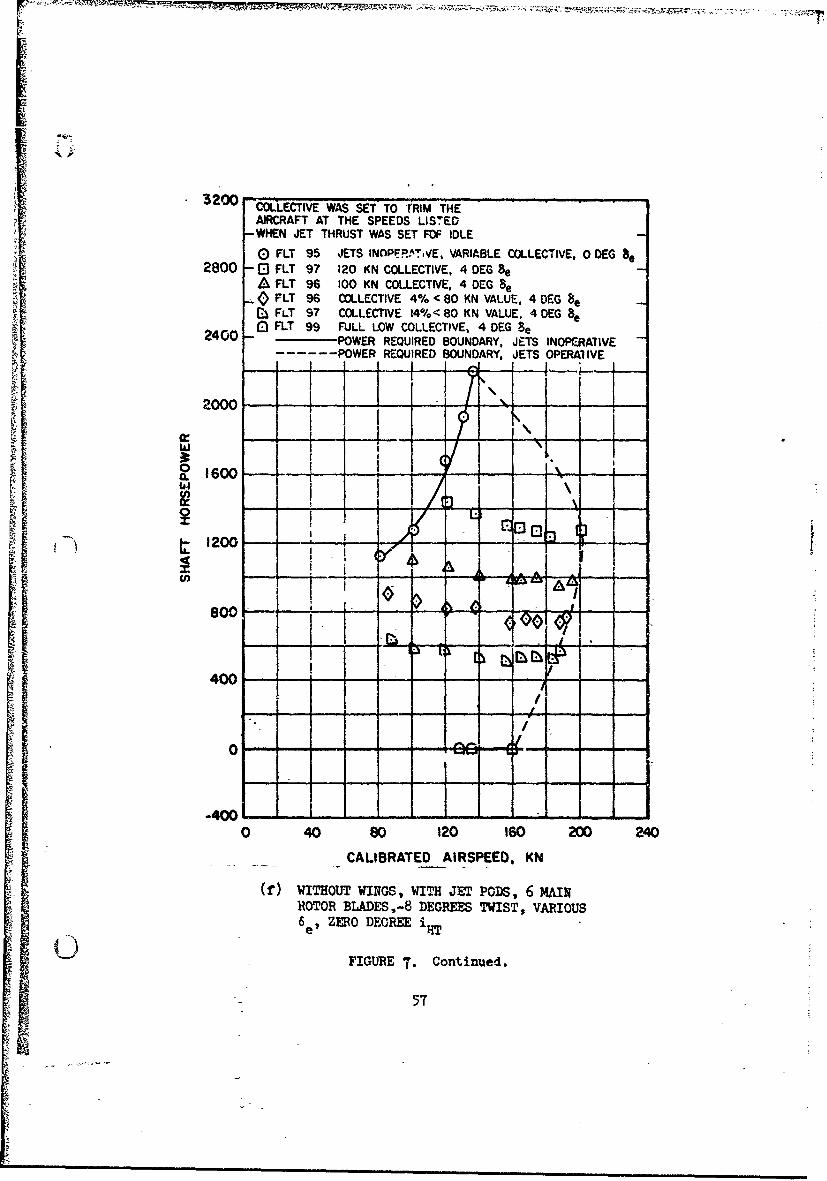
3200 COLLECTIVE WAS SET TO TRIM THE
AIRCRAFT AT THE SPEEDS LISTED-WHEN JET THRUST WAS SET FOF IDLE
0 FLT 95 JETS INOPERrT,iVE, VARIABLE COLLECTIVE, 0 DEG be2800 - El FLT 97 120 KN COLLECTIVE, 4 DEG Be
A FLT 96 100 KN COLLECTIVE, 4 DECG e-( FLT 96 COLLECTIVE 4% < 80 KN VALUE, 4 DEG 8e
r(j FLT 97 COLLECTIVE 14%< 80 KN VALUE, 4 DEG 8e2400 I FLT 99 FULL LOW COLLECTIVE, 4 DEG Be
400- --- POWER REQUIRED BOUNDARY, JETS INOPCRA71VE- ----- POWER REQURED BOUNDARY, JETS OPERAI VE
2000--j-
I- ___o___ - -1-*=a. 1600-
z 1200- - ,-.,SiI
Soo;
80100
400 -
,/
0 - -
-4001------- -
0 40 80 120 160 200 240
CALIBRATED AIRSPEED, KN
(f) WITHOUT WINGS, WITH JET PODS, 6 MAINROTOR BLADES,-8 DEGREES TWIST, VARIOUS6 ZERO DEGREE i
FIGURE T. Continued.
5T

2800
o FLT 136'0 DEG Be-. FLT 136 -2 DEG Be
2400 - - -...- -
00 1600
Ix
12000-
S• ,6~00...
w I
0 40 80 1200 2
' 800
¢ : 400
!•-0 40 "80 120 160 200
- CALIBRATED AIRSPEED, KN
(g) WITHOUT WINGS, WITHOUT JET PODS, FIVEMAIN ROTOR BLADES,-8 DEGREES TWIST, VARIOUS6 e, ZERO DEGREE i., VARIABLE COLLECTIVE --
FIGURE 7. Continued.
58

2800
0 FLT 1400 DEG 8 e"0 FLT 140 -2 DEG 8e
2400 -- 4-
2000 - -
0 1600ICLU0
1.-t200 - - -
400 -
0 40 80 120 160 200
CALIBRATED AIRSPEED, KN
(h) WITHOUT WINGS, WITHOUT JET PODS, FIVE MAINROTOR BLADES, -4 DEGREES TWIST, VARIOUS 6 eZERO DEGREE iHT, VARIABLE COLLECTIVE
FIGURE 7. Concluded.
59
i1

72 ....0 -4 DEG TWIST1
68 - D TWIST -f--I---. DELTA ESTIMATED FOR -4 DEG TWIST 1 i , , _
68 " USING GOLDSTEIN-LOCK METHODS--.-8 DEG TWIST Cp INCLUDES MAIN ___
"ROTOR TEST STAND TAIL ROTOR TEST-- L -JUSTAND, FIXED LOSSES AND 3%D,/ D I
64- II -- +- 1-,
60... .. / /x , i• u~C 60 7 I'
•1~~~ 562Jlj
-,
•. ' ~ ~48 . . . .. !
- • -
-- L''/-I
48
- ,i Ii ...
40 44 48 52 56 60 64 68
WEIGHT COEFFICIENT, CwX10 4
FIGURE 8. HOVER PERFOR.MA2NCE ,EFFECT OF BLADE TWIST B BASICHELICOPTER, FIVE, MAIN ROTOR.BLADES).
60

it
68 I i
0 6 BLADES(o-.04) i c'.I- 5 BLADES (o, r .078),
CORRECTED FOR GROUND EFFECT
SIi ! - ' I
' , - "P -" '-'* -- --"'--, -- -'T'-- • -t .-.'.... .. .x 6 0
t k .I• I IS56 B56 II t: i(E)I•.DELTA ESTIMATED BYi
I GOLDSTEIN-LOCK
-- --'- -" " 1 ---3-! - -' •
48-T - , -- -,o ,I ! i/I I ; I• I i -
_ I
III I ,
3 : 4 8 I :- '
WEIGHT COEFFICIENT, C'X 104
S1IGUE -9. HOVER PERFORMANCE EFFECT OF ROTOR SOLIVMT,(-4 DEGREE TWIST, WITH JET PODS).
61
44,1I'

76 - ,-[ FAIRING FROM FIG. 9. FOR PURE HELICOPTER I I- WITH DELTA ESTIMATED BY GOLDSTEIN-LOCK IMETHOD"]" "-'
72 PURE HELICOPTER WITH ESTIMATED 6 % Dv, ._L__.--4-7 .CORRECTION FOR WING, SPONSON ANDENGINE INSTALLATION
C) HELICOPTER WITH WING, SPONSON AND_--iT
ENGINE INSTALLED, CORRECTED FOR /68 GROUND EFFECT I-1-
0 PURE HELICOPTER - 1
0 6iUO
2
-~ I40 44 48 52 56 60 64 68
WEIGHT COEFFICIENT, Cwx 104
FIGURE 10. HOVER PmROpmANCE EFFECT OF WING INSTALLATION
(FIVE-1MAIN ROTOR BLADES, -4 DE.GREES TWIST).
62

CM 160 KN, BEFORE DRAG REDUCTION-- - -- - ---- 190 KN, AFTER DRAG REDUCTION--- 160-170 KN, AFTER DRAG REDUCTION
w 46 --
I42 -
X 38- --/]w
020 40 60 80 I00
WlNG-B0E•Y LIFT/q, FT2
- FIGURE 11. LI•"r DRAG POLARS.
63
hc
i • •

'C
50 -� " BEFORE .1DRAG RECtJbTION ...-- .- �- -AFTER DRAG REDUCTION
'C U... --
4w
•4 0 20 400 804 I00.1
I -042
Off
(b) WITh wmc•Gs, WITH s_FIGURE II. Conc. de4.,,
>146•

I.o
C) 000) -0~. totv LA
rr~-t1
---.- III~ 3 V3VI *65

A I -�-,.
.t ;
I4. -� V
4 -
-�
� )
4,
In
In4,
I,
C
IU)
'44'
.r4
cr�H
di
I NOT REPRODUCIBLEII
p

600 - " i- I•H3A rEST 'DATA
Ii 1---REFERENCE 4500FUSELAGE i i I
LEFT WING RIGHT WIN(,
400 - -
303I 0
200 I
w 0 0 -
a- -00
WING ROOT-.- -WNG ROOT-200 - - -
100 80 60 40 20 0 20 40 60 80 t00
PERCENT SEMISPAN
(a) V = 120 KNOTS, PITCH ATTITUDE = 1.9 DEGREES,YAW ANGLE =-4.2 DEGREES
FIGURE 14. WING LIFT DISTRIBUTION.
67
S .S"S~

i i
600---NH 3A TEST 'DATA
S400 -"•�-REFERENCE"'4
" 5300 ". , ..
4o. 400 /•i
SI ,
!i• ? -,oo ' .= ,. • • ,
$!
S300-' 0
• •. 200
.10
Soo •o 6 40 zo o o4ors om
600 NH 3ARCNTESEMIATA
z
a. 4100
C'2 00
/ Z
Y (b) V =1.64 KNOTS, FITCH ATTITUDE =2 DEGREESS~YAW ANGLE = -3.5 DEGREES
/*FIGURE 4. (CONCLUDED)
"-68
@O 0 O
WIGRO-,1-IGRO
*% = - •l•l • •il i i a • • l l l . . , l , • • • i i i • • li l I ' i l

7A,•
24000'
4V WITH WINGS, WITH JETS0 WITHOUT WINGS, WITH JETS
20000 UPPER STALL LIMIT- - ___
16000 . -
-3-
12000 -0
-4000 -00 -00 -OO 0 10 00 30
e,., 14.5-
-4000 -30ooo -2000 -Ao0o o 1000 2000 3000
ROTOR DRAG, LB
(a) 156 KNOTS (u = .40), FIVE MAIN ROTORBLADES, -) DEC-REES TWIST1 0 FIGURE 15. ROTOR OPERATING ENVELOPE FOR VARIOUS AIRSPEEDS
AND ROTOR CONFIGURA7IONS AND 660 FPS ROTORTIP SPEED.
69
- 'N.---

A
2-4000
d WITH WINGS, WITH JETS0 WITHOUT WINGS, WITH JETS'
20000 UPPER STALL LIMIT\
0A_ HP 01
16000 ----
d._j H~r23OA-
:312000--- - - . -d. /OETTHRUST- -~ LIMIT
0
8000 - -- -- -- - -
97.e14.5 1000
-3000 -2000 -1000 0 1000 2000 3000
ROTOR DRAG, LB
(b) 175 KNOTS (u=.45) ,FIVE MAIN ROTOR BLADES,
C -4 DEGREES TWISTFIGURE 15. Continued.
70

-f
20000
6 WITH WINGS, WITH JETS
0 WITHOUT WINGS, WITH JETS
UPPER STALL LIMIT- E 0
I I r-J12000
0n..• - JET THRU T LIMIT
8000
ALl
4000 0G.ýeI4.5-o/
0-3000 -2000 -1000 0 1000 2000 3000
ROTOR DRAG, LB
(c) 195 KNOTS (u=.50),FIVE MAIN ROTOR BLADES,
-4 DEGREES TWIST
FIGURE 15. Continued.
71
$

24000WITH JET " I I1T WIG, WITHJETS UPPER STALL LIMIT '
0 WITHOUT WINGS, WITH JETS
20000 I ' HP-O
HPx23oo-- i16000
; ~ ~~8o000I' \71o
"" T ý7ST4.MI,
S-4000 -3000 -2000 -!000 0 10(00 2000 30(00
i •ROTOR DRAG, LB
--. • (d) 156 KNOT (p=.4O),FTVE MAIN ROTOR BLADESi
S L -8 DEGREES TWIST
S~FIGURE 15. Continued.
II7

24000
SWITH WINGS, WITH JETS0 WITHOUT WINGS, WITH JETS
UPPER STALL LIMIT HP=O0
I I-Ii 16000 - ...
-I, OOO- - -0---
n- i 6• .__LIMIT00
8000
4000 j I1 .0 -1- -1 I-.- -a
-3000 -2000 -000 0 1000 2000 3000
ROTOR DRAG, LB
(e) 175 KNOTS (u=.h5), FIVE MAIN ROTOR BLADES,-8 DEGREES TWIST
FIGURE 15. Continut~d.
I 73
20000 _ _ _
dWITH WINGS, WITH JETS STALL
0 WITHOUT WINGS, WITH JETS
16000.--2-"-- -- i
o 1v
10 040 0------------------------ O
-3000 -2000 -1000 0 1000 2000 3000
ROTOR DRAG, LB
(f) 195 KNOTS (il=.50), FIVE MAIN ROTOR BLADES,.
-8 DEGREES TWIST
A "rIGURE 15. Ccntinued.I
•; = 1 • ,,4

24000 UPPER 'STALL LIMIT. -
0-4 DEG TWIST -1
20000 7 ..k .! -I I V/
LOWER STALL LIMIT HP=O
16000 -
ODI "P , t0ý CIItJET THRUST
OP LIMIT-
8000 ," ..
4000 - J .. 1i -
0
-4000 -3000 -2000 -1000 0 1000 2000 3000
ROTOR DRAG, LB
(g) 156 KYOTS (u=.4O), SIX MAIN ROTOR !:ADES
FIGURE 15. Continued.
75
L

I
S;tI
24000- - - -
0 -4 DEG TST
0•-8 DEG TWIST '
20000
P216000- "-1
-j1120000
00lo-0
J JET THRLST LIMIT
80000- - -- - - -
4000
-3000 -2000 -1000 0 1000 2000 3000
ROTOR DRAG, LB
C (h) 175 KNOTS (1=.45), SIX MAIN ROTOR BLADES
FIGuRE 15. Continued.
16

{I
240004 D-4EG TWIST I !
E)-80DEG TWIST- i; I 1--f20000- -
0 LOWER STALL LIM T-,,,,
16000 i~I-?-Z LIMIT. _I-" " ' ~~-4" TWIST t••
HP,,2300-
U---i12000
"6 , 0*ll'' JET THRUST LIMIT
8000-7- e~t. 1145,/ik" e e.sl.OO
4000--
0 -I -
-3000 -2000 -1000 0 1000 2000 3000
ROTOR DRAG, LB
(i) 195 KNOTS (v=.50), SIX MAIN ROTOR BLADES
FIGURE 15. Concluded.
77

116 -
CONSTANT ADIANCE RATIO (p)----- CONSTANT ADVANCING TIP MACH NUMBER (MT) -
0 CONDITIONS FOR BLADE SPREAD (O.A.T 23 DEG F)
1o2 - - -, •- -/•"!
\ "\\ ,
, ,,ii,i , lcrr
108
104- -
1I00
TRUE AREE , KN j\
96 // \/
9 4•140 160 180 200 220 240 260
TRUE AIRSPEEDl KN
-' FIGURE 16. COMPRESSIBILITY MAPPING CONDITIONS.
78

.
r i- RH
l'I C
00
-J
-0 z
ID .
o ~z
. I. x1
* ¶
-0
0 0 00 . 0 o0 ~ Q2 0 OSS0o 0 * -
918 V-1CNM dI 930otoNddVIJ ISd L-9t4 ISd'.LO
aoL)javi U18NI~VA HoiOmi ?.ivV uOJ0 N!VM
79

' i
0.8-
- _.04
w
c -.12w0
S-.=04 "-;AM 4' 65
4] z
0.- 2
.01
0- -.16r
BLADE ANGLE OF ATTACK
Q. FIGURE 18. BLADE PITCHING MOMENT COEFFICIENT VERSUS
AINGLE OF ATTACK AND MACH NUMBER.
80

u- 7-
!~~~~~~ -o-_--------• --- •
"-10
40
wJ 20
- 2 0 -"...
0I
10
%II
w ------,, .2... AZMT ANLE DEGI•"
00
FIGURE 19. ANALYTICAL REPRODUCTION OF BLADE SPREAD.
I81

AU1
o0 ~i.co C) L
0
Z E-Z
-- -- ILI' .
OD
Ii '-4E-4
I - C E-4
* I 0
0,
qwo '1LN3101-4f3oO ao-1 '1OW.NOO
824

.O.
.012
. . ...0.. 8....E
C-)
wo_ 008 - -
00.00640 10
0o0 o0 o0.004 ........ .- ?-- ~ -- - -- - - ~
00 _
o .002.
0 001 f02 003 .004 .005 .006
CHANGE IN TORQUE COEFFICIENT, A Co/ol
U FIGURE 21. (HA14GE IN CONTROL LOADS AT POIPTS ABOVETHEORETICAL STALL LIMIT.
t 83

----- CORRELATION BASED ON -4 DEG TWISTCORRELATION BASED ON -8 DEG TWIST
.... CH-53A TEST DATA, -6 DEG TWIST,
44
0 GR WT= 35,000
V0
+1 3 1i
2I
CORRELA.ION AS 'L ON CORREL WIST CH-
CALTESTBDATAD-6RDEGET T, NI
I't
C GRWT~3,OOO-. '
FIUE-.30TO OD 2EA'O WT H5A

I!
If_ , ~~too . . .. . . .- CORRELATION BASED ON -8 DEG TWIST
i i -J .---- CH-SC TEST DATA, -8 DEG TW:ST, ....V) GR WT I9,000S• ~~~800 - ,- ..
40 -~4 0 0 [ . . .. . . . . . ..-
0 40 80 120 160 200AIRSPEED, KN
FIGURE 23. CONTROL LOXY'S CORRELATION "TTH CH-3C.
85

CONSTANT' PUS, H ROD LOAD CONTOURS
--...- THEORETICAL ROTOR OPERATING ENVELOPE
24000 ] S
UPP,:'R STALL LIMIT . .
SI- '- " - -., -" I
20000
/'.,0.._- - , ,.,600 L-I
1 5000L
8000- HLB' COLLK
4000 o_
I x
-3000 -2000 -1000 0 1000 2000 3000 4000
ROTOR DRAG, LB
( FIGURE 24. CON IROL SYSTEM LOAD CONITOURS AT 175 KNOTS(FIVE MAIN ROTOR BLADES, -8 :)GREEs TWIST).
"86
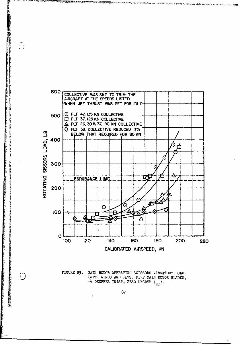
600 COLLECTIVE WAS SET TO TRIM THE TAIRCRAFT AT THE SPEEDS LISTED I
I • WHEN JET THRUST WAS SET FOR IDLE---
500 0 FLT 47,135 KN COLLECTIVEO FLT 37, 125 KN COLLECTIVE
] A FLT 26,30 3 37, 80 KN COLLECTIVE0 FLT 38, COLLECTIVE REDUCED 11%"-
B LOW ITHAT REQUIRED FOR 8 KN
6400
S200 ... F
0
II0
0 ,......rn -
100 120 110 160 180 200 220
CALIBRATED AIRSPEED, KN
FIGURE 25. 14AIN ROTOR OPERATING SCISSORS VIBRATORY LOAD(WITH WINGS AND JETS, FIVE M4AI ROTOR BLADES,-4 DEGREES TWIST, ZERO DEGREE i 1T)
87
L

C--
-r -o --
w x 0J
LU MJo L
Q--- 5 >
-7-
~DwW 0
WjCj
ww.J -~LAJ~ LL;
wo, z ILL- ,Ll
o 0 0 0000 8 00
81 'GVO71 S;8OSS13S A8iVNOI±VIS
88

WITHOUT WING, WITH JETS , j
M 6000 'J, ___u•WITHOLUT INGS AND JT
"'ii4iiii
S4000 '" ".-..,: '
<0 L-Wl'TH WINGS AND JETS
!a I'
0 40 80 120 160 200 240
CALIBRATED AIRSPEED, KN
FIGURE 27. BLADE STRESS AT 70 PERCENT RADIUS VERSUSAIRSPEED ( FIVE MAIN ROTOR BLADES, -h
DEGREES TWIST).
89

0
- --
_
I
0 ES =2
,W 0
0
C')j
i-4
gooCC
I '-9O
tVz
iii~

S~8000•
S~~5 BLADES ,"
600
U)
"a -4000Sw 6 BLADES
i J"w 20001.
0 100 140 180 220
CALIBRATED AIRSPEED, KN
FIGURE 29. EFFECT OF NUMBER OF BLADES ON BLADE STRESS, WITHAUXILIARY PROPULSION, (-4 DEGREES TWIST).
91A

16000 ,' , , ,"0 FLT 95, -8 DEG TWIST, BR-6
L3 FLT 85, -4 DEG TWIST, BR-7- " FLT 86, -4 DEG TWIST, BR -7
2 0 0 FLT 90, -4 DEG TWIST, BR- 7
cr
w 8000
w
w 4000
0 120 160 200 240
CALIBRATED AIRSPEED, KN
FIGURE 30. 3FPFECT OF TWIST ON MAXIMUM STRESS, WITH AUXILIARY
PROPULSION, (SIX MAIN ROTOR BLADES).
92

0(
8000 10 DEG RUDDER
-----10 DEG RUDDER -
iL --- 20 DEG RUDDER
k 0e
I-I
2000
120 140 160 180 2z0
INDICATED AIRSPEED, KN
FIGURE 31. EFFECT OF RUDDER DEFLECTION CN TAIL ROTOR STRESSES.
93

c*1
0 .(r
00E-
z CD Ila
(D U) 4 %
.- 6
0~ 7..w
iLi
w~~ 0 ;2
00 - -
E-Cr ~*O0
- - E N
I-n
(i~ 9; 'NOUJ831307VAHMBOVIA Ji10300

- LATERAL RESPONSE TO LAT~irAL EXCITATION----- VERTICAL RESPONSE TO LONGITUDINAL EXCITATIONS---VERTI'AL RESPONSE TO VERTICAL EXCITATION
-i\-- 1i- ;I
imi
S.2-
+1~~
aU.
0) IX0
5/R 6/ REV
0L
400 600 800 1000 1200 1400
EXCITATION FREQUENCY, CPM
FIGURE 33. NH-3A COCKPIT RESPONSE VERSUS FREQUENCY.
95

Ism
0 0
C))
U.,
-8E-
0U
H cr0-
o 0o 0
ISd 'SS38 Is A8O.LV881A
.L80ddflS NQ!SSIVNSNV8J
916
IV

W <7,
ww
(1)1
zl 0
0 owz -
Zu)> b
0 i3 0
0 6 6 0 6i
OT NOLL.VH313..,V M~OLVSAIA itidM.303
97

1)
Awl
f)
2.4 F A G -" Y ' LB ' ''' ' ..24 FLAED SYMBOLS INDICATE 0 -DIVE'
WHEN JET THRUST WAS USEr I 'Q LEFT TURN
- -- - - -- A AUTOROTATION ENTRY-
.0
1r4< 1.6
0 -
0.8
0.4
0 40 so 120 160 200 240
INDICATED AIRSPEED, KN
(a) WITHOUT WINGS, WITH JE. PODS, FIVE(,MA. IN ROTOR BLADES
FIGURE 36. V-14 DTAGRtML FOR VARIOUS AIRCPAt? CONFTIGURATTONS.
98

2.8 FLAGGED 'SYMBOLS I'NDICATE ' 0 'DIVE "
WHEN JET THRUST WAS USED Q LEFT TURN'A RIGHT TURN
I DYNAMIC RESPONSE2.4 - - J-,- [ AUTOROTATION ENTRY-
2 2.0
Sz0\
1.2
0I[ ~~0.4 t•
0 40 80 !20 i60 200 240
INDICATED AIRSPEED, KN
(b) WITH WINGS, WITH JET PODS, FIVEMAIN RBOTOR BLADES
FIGURE 36. Continued.
99

£(
2 .8, .- , ,-, ,,, , , , ,
.FLAGGED SYMBOLS INDICATE 0 'DIVE
WHEN JET THRUST WAS USED 0 LEFT TURNI - .- ~AUTORCTATION ENTRY-I I
•. ii I
"2.0
z
cr 1.60 --0 • 1.2----
0
0.8-
0 40 80 120 160 200 240
INDICATED AIRSPEED, KN
(c) WITHOUT WINGS, WITH JET PODS, SIX MAINROTOR BLADES
FIGURE 36. Concluded.
IGO

IC - _ _ _ _ _ _ _ _
----THEORY, RE (7)S --- FLT q2-' )
40 -0 J
I -
-
i -- - - - ___WC.,
o20
£ ,,10 - - ----
ow
~0
0 10
-12 -8 -4 0 4 8 12 16
SIDE SLIP ANGLE, DEG
FIGURE 37. LATERAL DIRECTIONAL STATIC STABILITY AT 125 KNOTS,(FIVE MAIN ROTOR BLADES, -8 DEGREES TWIST, ZERODEGREE i HT).
S1 101

I
14SSPECIFIED12 -! t- 4- - -,,o
w 0>0 a__
w_J 8 - THEORETICAL RESULTS --
0 0FLTf 26-So , i ,I I
_4) 4 1 -Lwo
0-
-4
00
z-
0
60 100 140 180 220CALIBRATED AIRSPEED, KN
FFIGURE $3. CORRELJATION OF STEADY STATE FLIGHT PAR1ETERS (WITHW: GS AND ET, FIVE MAIN ROTOR BLADEU , -4 DEGREESTWIST, -35 DEGREES 6 , ZERO DEGREE 6, 5 DEGREES iHT
102

I6z
a-4
il--
Z 0"25
z
oo I,.. .W 4
00
4 10
0 1 1
Iv j - - -__- .- I
4 o
60 000 140 180 220
• ~CALIBRATED AIRSP'EED, KN
FIGURE 38. Contnue.
103
i4

c 0 -
tO 1- 0
6000 - --.- .
SPECIFIEDS~~5000 i
"J4000.
"I.-
3000
2000W
1000--
22000
20000
0 -j 18000 Z
16000 ---
14000'- - - -- - - -
15000 160 100 140 IB 220
CALIBRATED AIRSPEED, KN
FIGURE 16b. Concluded¶
ol4

x20
20 0 FLT 39, BEFORE ORAG REDUCTIONi ;, I[Z]~~- FLT 45. AFT.ER DRAG REDUC•T"~_. .. . . .
FOR FLT 39 AT 199 KN 2 DEG So
151
, FLAPPING LIMIT-'¢::r ± ( 4 -
5
0
0
--T"--I-.; II I i 10.n ... .. . . .4__ _,_ _
2 01 -, _.- -i ! .... i ..I I0 i i !
"lot IOO I_ I__ m____________
,TF• ~--T - I-
i, I I i i
Ix joF
0 I00 120 140 160 10 200 220
CALIBRATED AIRSPEED, KN
") ~FIGURE 39. EFFECT OF DRAG REDUCTION ON STFADY STATE FLIGHT PARAMETEB•S,"• (WITE WINGS ANDi JET!S. FIVE MAIN ROTOR BLADES, -hI DEGREES
TWIST, ZERO DEGREE 6e, L DEGREES 6,. ZER DEGREE iT).Leo5
1u5

{A
NOi.ATERAL C04JTROL READOUT I
C.).70 tt•
Ua- 4-.........- 0 -._ • _ +
) 40- - ---
; ; -- : .... I-T -.J, 2 0 .
S.. . . . . . . . . . . . , - 4 - -- -- -
P 60 . ..
-oo
60007-
80 • •- .. ..--- ,--r--± --;- ----- I.
U A
6000
-~----I"-- --I ' --- -" 2000---
0 00 120 KO4 160 180 200 '220
CALIBRATED AIRSPEED, KN(
FIGURE 39. Co.cluded.
io6

z
ol w
- N 0Cl
wO 0w -w__ _
tj jI- I I_ _ _ _
oCL.t~ LLLJ
0
I 0E-4oNzi 0
0 '-0
M OWI rz..
o~. ox 00
o 0 0 0 0o (0 N0 N O
81 'OVO1lNPAOQ -1.1V LVNOZI1iOH
2:07

10 1 1 1 1 FLAPPING RECORDER
z Z FLAPPING LIMIT OUT FOR FLT 14
a.. 0 FLT 14, WITHOUT WINGSUI < 5 -FLT 26, WITH WINGSa. A , FLT 25, WITH WINGS
- 0
w 0X
-0
0--~------------------- L
IJ° I I
80'• a-
S60C
40-
S; 80 " iO0 120 140 160 ISO 200
CALIBRATED AIRSPEED, KN
. FIGURE l1. EFFECT OF WING ON STEADY STATE FLIGHT PA7.PNETERS (WITH JETS,FIVE MAIN ROTOR BLADES, -h DEGREES TWIST, ZERO DEGREE 6-15 DEGREES 6f, 5 DEGREES i HT)
108
t

I00-o F LT 14. W!1401JT WINGSO3 rli 26. WIT WINGS ~-~1
AFLI 25., win- WINGSii-iii
S, _ _
20- --------- ; it
0--
40
6'000
4000 -
20C 80 10 120 140 160 IS0 200
CALIBRATED AIRSPEED. KN
FIGURE ii. Concluded.
109
A° l i. . . I !

~7~-~;- ___
C,)FZ§, 7 1--- I-. *OD
z F
Sc 12
~ j I -V
(30
>* 0
ON0 '3Gfn~iuv HO.Ild 30V13S(W
110

00
W -4 f
P- E-0 :4
__I- = 0
- -
*> 4
0 0 0 0 0
39imj-Vqn9I

C~
1hz -3sz -Izjan zzO
112

I7
z FLAPPING LIMIT-.OL. I i I I0 0 FLT 71,5 MAIN ROTOR BLADES
U-I o0 FLT 95.6MAINROTOR&AIDES -
-0
o
1015:3 .
I'--W 0 -
-01
00
0 0 0060 608600 10 1406
CALIBRATED AIRSPEED, KN
FIGURE 44. EFFECT OF SOLIDITY ON STFADY STATE FLIGHTP.49RAMTERS (WITHOUT WINGS AND JETS, -.8 DEGREESTWIST, ZERO DEGREE 6 e ZERO DEGREE i.).
4 113

1>0
I
-" 80
U-
_j 60
n- 40 -IwL
100
C.)v
Sw 60
S40 --• -"
,.. I :
100r
40
80 60. 80 10 10 4 6
'•CALIBRATED AI RSPEED, KN
SFIGURE 44. Concluded.
C 1

FL 9
101
r--0
-10
80 • .. , , ,
7-20--o
T5 60
0 2 4 6 8 10TIME, SEC
FIGURE 45. CORRELATION OF DYNAMIC RESPONSE OF --USELAGE ATTTUDE TO ALONGITUDINAL PULL AND RETURN AT 120 KNOTS (WITHOUT WtNGS, WITIRJETS, SIX M4AIN ROTOR BLADES, -8 DEGREES TWlST, ZEPO DEGREES 64,ZERO DEGREE iHT)1
1]15

280
0 NH- 3A WITOUT INGSAND ETS
Z:4 TWIST, 17,000 LB GR WT
1-~60 ...
12 0
~- 80 . . . .
40
20
0
2z
0C __ ___ ___ ___
32
S40--v-
TIME, SEC t
FIGURE !t6. COM4PARISON OF NH-3A AND SH-3A. DYNAM4IC RESPON1SE.
3.16

101
FLAPPING. LIMIT_
rCD
0 FLT 60, -2 DEG 8.S- ---a FLT 56, 0 DEG8.
0-
$ o -- ~ i zI 1
--I0
40 0I---i61C
100 " .NO RUDDER DATA AVAILABLE, - -
FO FLT 53 i ,80
40 2
0 80 100 120 140 160 180 200
CALIBRATED AIRSPEED, KN
(a) EFFECT OF NEGATIVE ELEVATOR DEFLECTION
FIGURE 47•. EFFECT OF ELEVATOR DEFLECTION ON STEADY STATE FLIGHTPARAMETERS (WITH WINGS AND JETS, FIVE MAIN ROTORLBLADES, -8 DEGREES TWIST, h DEGREE& %f, ZERO DEGREE
HT
.. ?
-.. 4

10--
p 3~~~00 ~- - -
80 -
L..I i I i' --
- - - - - - - - - --- - -- -- -- -- -----
,• 40
d t _ I i
46) man~- - -a- Q -
-JJ00
I-s ! ,-~ -. -
co
200 --- i-------
I T
-Tm. i- I - -
o so 100 120 140 160 ISO 2C CALIBRATED A16SPIEEO, KN
FIGURE" 4. (a) Contirjuer.-
11

10
Z FLAPPING LIMIT
0 LT 67,a. 5 _ElFLT 68, 6DEG Be
,.,, o ....... •10
0-
101
0
n, I0 -- - -
i" I' I"""o I
0 0 0 II I4 I6 8 0
01
so
S60 - - - I
80 e 100 120 140 10 180 200
CALIBRATED AIRSPEED, KN
FIGURE 47. (b) EFECT OF POSITIVE ELEVATOR DEFLECTION
119
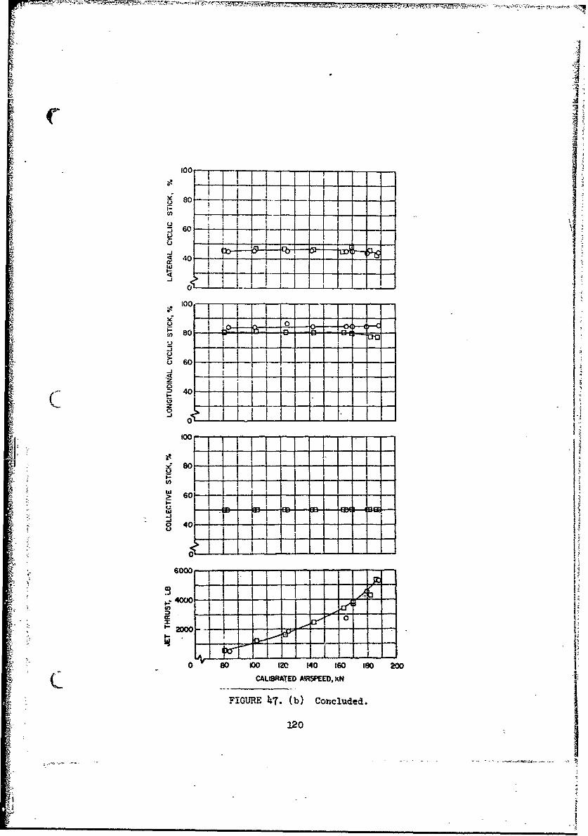
r r4
w
"too
Coo I I'
-J I
so - - -
60
t Ioi
60 I° I I I
6000 'I 1
• ! i i --! L
InJ
~00 ~0
I" A I I
0 O0 00o 120 140 160 to0 20
C ~~CALISRATED M!SPEEO, XN 1
FIGURE 4iT. (b) Concluded.
120

- , . ,
-~ __ FLAPPInG LIMiT4
WI 50 FLT 130, -10 DEG ,.
L El BFLT 130, -W DEG 8,
r- -
. i I I I
0.
-10 - -
-I I - o I lli
40,
* LI~III I I
0 100 :4 0 140 160 180 R00
CALIBRATED AIRSPEED, KN
FIGURE 48. EFFECT OF RUDDER DEFLECTION ON STEADY STATE FLIGHTPARAMETERS (WITH{ WINGS AND JETS, FIVE MAIN ROTORBLADES, -4 DEGREES TWIST, ZERO DEGREE 6 , ZERO
DEGREE 6.,, ZERO DEGREE I eH
1.21

g;-
100------------------
S80 - - --
:3 60 _
44
w I>- 4
.4 i
• 0 10 1 ...... 0 18 '0
C,.FC-) V
F1L Conclude.,S_16022
SI-I
40.
F= bI• - -S. Co-udd
: 122
2,

1/12 SCALE MODEL WIND TINNEL DATA
Tests of a 1/12 Scale Model of the NH-3A air _,pe,shown in Figure 49,were conducted in the United Aircraft Corporation h x 6 feet Subsonic
Wind Tunnel prior to modifying the bailed SH-3A aircraft. Six-component
aerodynamic data were obtained over ranges of model pitch and yaw at a
constant tunnel dynamic pressure of 25.6 psf, corresponding to a nominal
tunnel speed of 100 mph.
This append'cx is intended only to provide the most significant data
used in evaluation and correlation of the NH-3A flight test results. Data
are presented in Figures 50 through 54 in terms of full-scale aircraft
forces and moments per unit of freestream dynamic pressure. All quantities
are in the wind axis system, through the aircraft c.g., and are corrected
for gravity and interference tares. Unless specifically noted, tail inci-
dancei flap deflection and elevator deflection were zero. The model was.f
equipped with a non-rotating simulated rotorhead. Streamlined fairings
were incorporated to provide smooth flow about jet inlet and exhaust
locations.
Figure 51 presents the effects of the wing and tail upon airframe
longitudinal characteristics over a range of angle of attack. Lift, drag
and pitching moment parameters are shown for the compound configuration,
the helicopter plus jets (compound with wing removed), and the helicopterwith jets, but with the horizontal stabilizer removed. The minimum para-
site area of the compound configuration was measured as 18.5 square feet.
This was initially corrected to 26 square feet to account for protruber-
ences, leakage and details whose drag could not be accurately assessed on
the small model. A further discussion of the actual drag was presented in
Aircraft Drag, page 15. The pitching moment curve of both configurations,
with the stabilizer installed, was highly stable. •'igure 51 presents
similar dat'. without discussion, showing the effects of flap deflections
O of 0, 10, 20, and 30 degrees.
123
II

A
Figure 52 presents the effect of elevator deflection and Fiur
shows the effect of stabilizer incidence upon longitudinal charact(
The small differences which may appear betu.een data of similar config k-
tions in Figures 50-53 represent the wind tunnel measurement accuracy,
because a separate run was conducted in each case.
Figure 54 shows the effect of yaw angle upon side force, rolling and
yawing moment pardmeters. The yawing moment is neutral or slightly
unstable at small angles of yaw, probably because of the reduced vertical
stabilizer effectiveness in the rotorhead wake. The positive contribution
of the tail rotor makes the full scale aircraft directionally stable.
1C
124
-

S --- C- W - * iujrq�s�
LI
KF /
F!it
H00I fri
Ir .1-I
0HSUU)
('UH
H
SI
0'hSn
NOT REPRODUCIBLE 4 V
�3,4>7� '4 r�4
t _________________ A
Vt)
it
I
-� -� -' - -
A - A

400SYM CONFIGURATION
0 COMPOUND HELICOPTER .
S0 A HELICOPTER + JETS W/O HORIZONTAL TAIL _ _
120
:2000 c.
Il-
-f 0
w 0 -_ _.__ -, i I
-10 L L
-2000
-24 -16• -- 0 a t i-
ANGLE OF ATTACK, DEG
CFIGURE 50. EFFECT OF CONFIGURATION ON LONGITUDINAL CHARACTERISTICS,1/12 SCALY AIRFRAME MODEL.
126
-• . . . ..i .... - " • ! -- _ - i .. . I

F 400 ISYM 8
0030
-400 .-.- K . -
2ww
w 0
12
0-2000
-2000-6-24 16-8 08162
ANGLE OF ATTACK ,aDEG
~0 FIGulE 51.. EFFECT OF FLAP DEFLECTION ION L011GITUDYNALCHARACTERISTICS, 1/12 SCALE AIRFRAM~E MODEL.
127

-- ;0
-100
uii
~,0I
000 040
a:a
I- 2000 -1 - 8162
IGIt

200 . '- I ISY il' HTo o
' 200
- 0.
""-2�o -. 120
'--200 -
so o3 'A't40
-24 -16 -8 0 8 16 2-: -
ANGLE OF ATTACK, c, IDEG
FIGURE 53. EFFECT OF HORIZONTAL TAIL INCIDF1CE ON LONGITUDINALCHARACTERISTICS , 1/12 SCALE AIRFRAME. MODEL.
J29

III
200'
0 0w
a -1 - -w•o.. - .-
0 S ..... oo
400 4
0.
--- - -. .. 0 8 is 2
130
e• r__L__L"• i ,J ! i I / I ,ooC 0 [ '!) ,• oo_ L • __ i I ,I , , ,
!• : ! o-
400 ! -\ i ,tal --- - i I - - - . . _ _
7 ~~~~i--- 1 1 -
"N ' k ....... . .. a.a.a
Q FIGURE 514. EFFECT OF FUSELAGE ATTITUDE CN LATERAL AND ROLL•- CHARACTERISTICS, 1/12 SCALE AIRFRAME MODEL.
130

APPENDIX II
TEST iNS12FUVIEWLIKI I0N
Test instrumentation was installed to record flight test data on
handling qualities, performance, rotor loads, stress, and aircraft
vibration for all configurations investigated. Dual instrumentation
was required in some areas to provide simultaneous indications to both
the pilot and the oscillograph/photopanel recorders, or to provide
back-up for the principal parameters. Instrumentation was also provided
to monitor critical structural loads. A description of the basic
instrumentation parckage is provided in the following sequence:
1. Apparatus2. Calibr-4ions •
3. Measurements
4. Accuracy
APPARATUS
Primary recording devices, installed in the cabin area, consisted of
two 50 channel light beam photo-recording oscillographs and a 24 hole
photopanel, utilizing a variable speed 35 mm camera. Signal conditioning
for the transducers was provided by standard bridge balancing modules and
potentiometer adapter boxes.
A nose boom was utilized to obtain airspeed, altitude, fuselage angle
of attack, sideslip angle, rate-of-climb and static pressure. The
original aircraft airspeed system probe was also operational and used as the
primary system when the nose boom was removed.
Wire-wound poteniometers were coaxially mounted to sense the angular
motions of the longitudinal, lateral, collective, and rudder pedal controls.
Similar installations utilizing angulators measured flapping, feathering, and
lag angles of the master main rotor blade. Tail rotor flapping and pitch
were measured with wire-wound potentiometers.
00 '13!4

-• • v - -• ° ,x- x_• _ • .. r : • •;-,j• o . '• -'- : • •• . . =
Vibrations were. sensed by ve.ocity pickups and accelerometers.
Vertical acceleration at the center of gravity was measured with a load
factor type linear accelerometer. Pit•-h and roll attitudes were
measured with a vertical gyro. Pitch, roll, and yaw rates were measured
with rate gyros.
Stress and load transducers consisted of" electrical strain gages
wired as conventional single active gages or as 2 or h gage tension or
bending bridges. Strain gages normally installed on the leading edge of
the main rotor blade spar were removed to the trailing edge to prevent
unnecessary drag effects. Internal wiring was provided for the instru-
mented main rotor blade during fabrication. Wing bending moment measure-
ments wert made by strain gaging Ghe fore and aft wing spars at two span-
wise locations. Wing lift was determined from the difference in bending
moments between these two locations.
CALIBRATIONS
Instrumentation items were laboratory calibrated prior to installation
C .n the aircraft. Preflight and post-flight calit-ations were made for all
oscillograph measurements with the exception of the velocity transducers
which only required periodic calibrations. Aircraft rigging checks were
made throughout the test program as requ;.red by main rotor blade changes.
All data presented herein are corrected for instrument and installation
errors.
Airspeed position error calibrations were made for the aircraft and
nose boom systems to calibrated airspeeds in excess of 200 knots. The
calibrations were conducted using the measured speed course method. Results
of the airspeed calibrations are shown in Figure 55.
Turbojet thrust determination was made by utilizing the engine manu-
facturer's test cell calibration data, which included engine pressure ratio,
net thrust, corrected fuel flow, and corrected engine speed.
Calibrations of control positions, blade motions, gyros, accelerometers,
Sand pitch and yaw vanes were straightforward and will not be discussed here.
The control system rigging is prebented in Table III.
132
'7A

x Values of main rotor thrust wert oblari•d by diL'eet m.easurement of
axial. strain in the maid rotor shaft. Laboratory calibrations that
included effects of shaft bending and torsion on the thrust showed
repeatable, linear results. As testing proceeded, however, it v. and
that the influence of main rotor gearbox temperature resulted in a shift-
ing of the zero thrust reference. Further investigation of the problem
was undertaken with a temperature probe in the main rotor gearbox to
establish a relationship between the thrust readings and the temperature
gradient. Results of this calibration indicated that five minutes of
hovering at moderate temperatures and 10 minutes in cold weather would be
sufficient to stabilize the thrust reading and provide a good zero
reference. All subsequent flights required an appropriate hover and zero
reference calibration prior to the actual data acquisition flight.
Laboratory calibrations of the wing spar bending moments in terms of
wing lift, with the center of pressure at various spanwise and chordwise
locations, showed repeatable results. However, upon installation of the
wing on the aircraft, it was found necessary to replace the attachment
bolts with tapered pins to ensure symmetrical distributions of wing loads
among the four wing attachments. Even then, a continuing erratic
behavior of the wing lift data remained. As a result, the wing/body lift
was determined most reliably from the direct measurement of rotor shaft
thrust in combination with gross weight.
MEASUREMENTS
Oscillograph and photopanel measurements recorded during the test
program are given in Tables IV and V. The individual paramneters recorded
in each of the configurations are noted by an asterisk (*) in the Tables.
ACCURACY
The estimated accuracies of the measurements are presented in Table VI.
These accuracies are based on best engineering estimates at the conclusion of
the test program.
133

220 1 1 I [0• FLT '5 0 DEG ELEVATOR, JETS INOPERATIVE, NO WINGS /0l FLT 9 0 D•EG ELEVATOR, JETS OPERATIVE. NO WINGSA0 AA~AFLT 19 -15 DEG ELEVATOR, JETS OPERATIVE, NO WINGS /,
ISOzV
202 r204 1 60 - - 0
0 LT50 ECEEATOJESIBIRATIVEAINOPWENGSKN
A FT9 FI DGURELEV .ATORESOPERATCVEBNOTWINGS
w~~ - AI-IRFEAL
1- k
180----- --
wBOMSSE
S120 - - - /BOSSE
z
100- -
0 80 100 120 140 160 160, 200 2-20
CALIBRArEO AIRSPEE, KN
FIGURE 55. AIRSPEED CALIBRATIONS.
-134

. . .* . . .. .
*\I qC~ COO' 00O HO\ C) COO V\
L(\ cmt *0) O\ 0 0.C \OaZ 0~~L\
~~.Z CCJ Hr4 H II i'J i
0
IO H : cl 0J* HCO HCf\ c0\ 0 0 u CO
t-D a\c Cj *t *- Cnt- 0 ýO 10"\
'A~ 00 r- t-t- \O co -4* tU\
o* C\u 04 H I iI tcm
E-4 .
:, *C:J tA-t ULt UA\ O
t.0 oLCO 0.3 0 Ht- In\ 00 %J:) rf
W 0 .41
H- 1 s 0 *x 4
00 0
C.)
E- HL-4 HH ~ -: E-1E --
0 1 3 A . - .4 -0H H 0 0 H H H H
IL) C) 0 0 0
E- 00 HO 0- rl0 r0 HO 0 -0 HOA
0CD) 4 0 0 0) 0n 0a U )U co 0 0d r c
II Ott 0 40 40 g 0 10 1 0 00 0 4p
HHH
E-4 0 C4 jP
O C) E4~C.) 1.H
00 0 4 0
135

TABLE IV-OSCILLOGRAPH MEASUREMENTS
CONFIGURATION
1. Helicopter plus jets, 5 blades, *40 twist.2. Helicopter plus jets, 5 blades, -8° twist.3. Helicopter plus jets & wing, 5 blades, -4 twist.4. Helicopter plus jets & wing, 5 blades, -80 twist.5. Helicopter, 5 blades, -40 twist.6. Helicopter, 5 blades, -80 twist.7. Helicopter plus jets, 6 blades, -4° twist.8. Helicopter plus jets, 6 blades, -80 twist.
MEASUREMENT CONFIGURATIONS123 4 5678
Longitudinal stick positionLateral stick position
Collective stick position I'i:* :::;H :Rudder pedal position i**I *IIPicatiue*i* I***!*
Pitch attitude jRoll attitude •*i*i* *•* ***M. R. blade pitch . iM. R. blade flapping ** *M. R. blade lag 1*M. R. blade total stress TE-I * **M. R. blade total stress TE-4 * *
M. R. blade total stress TE-7 •*1*i* *i* * *
M. R. blade total stress BR-6 I*&**i* I - I
M. R. blade total stress BR-7IIM.R. blade normal bending stress NBR-I ***
M.R. blade normal bending stress NBR-35IM. R. blade normal bending stress NBR-5 *I-I* I , *M. R. blade normal bending stress NBR-7M. R. blade normal bending stress NBR-9M. R. blade torsional stress Q-2 1* ** ** *M. R. blade torsional stress Q-4 * * j* **S~~M. R. blade torsional stress Q-70.{i [
M. R. thrustM. R. shaft torque .*I* * * * *M. R. shaft longitudinal shear force (X) * *1 IM. R. shaft lateral shear force (Y) * * IM. R. .aft total shear forceM. R. shaft longitudinal bending moment (X) ** IM. R. shaft lateral bending moment (Y)**M. R. shaft bending stressM. R. push rod load l*l* 1 " i
136

TABLE IV (Continued)
MEASUREMENT CONFIGURATION123h5678
M. R. stationary -. issors load ,M. R. rotating scissors load * * * ** *M. R. spindle edgewise bending stress *M. R. spindle flatwise bending stress ,
Right lateral stationary starload * * * * * * * *M. R. head total stress UP-1 *M. R. head total stres UP-2*M. R. head total stress UP-3 *
M. R. head total stress VH-1 *M. R. head total stress VH-2 *1M. R. head total stress VHR-2 *
M. R. head total stress VHR-lM. R. head total stress VHR-l 1*M. R. head total stress VHR-3 *** *
T. R. blade pitchT. R. blade flapping * *
T. R. blade edgewise bending stress LR-TR *T. R. blade normal bending stress NB-R * *T. R. blade total stress L-1 *T. R. spindle edgewise bending stress * * *
T. 3. pitch beam bending load * * * I4 ) T. R. pitch actuator arm load * **
T. R. shaft torque ,, * ,I, .**,,
Tail pylon total stress P-1 * * *1* ***'*Tail pylon total stress P-2 * I
Tail pylon total stress P-3 * *Tail pylon total stress P-4 * A
Tail pylon total stress P-5 *Tail pylon total stress P-6 * *• * *
Tail pylon total stress P-7 * *
Tail pylon total stress P-8Tail pylon total stress P-9 A
Tail pylon total stress P-10,Tail pylon total stress P-11 * * *1*
Tail pyloa total stress P-12Tail pylon total stress P-13 *1*
Tail pylon total 'stress P-14 *
Tail pylon total stress P-15Tail pylon stotal stress P-16Tail pylon total stress P-17, * *Tail pylon total stress P-18 j *
Tail pylon web total stress PW-l
Tail pylon web total stress PW-2 *
Tail pylon web total stress PW-3Tail c:one total stress TC-l 1*Transmission a, 3!a total stress WSL-L3 ' * * **ITransmission a&'ea total stress TLF-160A I *' ' *1*Transmission area total stress TRO-18 * * * * *,*
137

W ITABLE IV (Continued)
MEASUREMENT CONFIGURATION1 *2 3 Is 5 6 7 8
Transmission area total stress TLO-18 * .Transmission area total stress TRR-160F *Transmission area total stress TRO-16A * * I *Transmission area total stress TRO-15ATransmission area total stress TLFF-6 * N ..Transmission area total stress TLF-160A-2Bendix coupling total stress C-IBendix coupling total stress C-2 *Jet engine attachment total stress EA-IJet engine attachment total stress EA-2 1*Jet engine attachment total stress EA-3 i**
Stabilizer total stress RST-l 1iStabilizer total stress RST-3 1*Stabilizer total stress RSB-Stabilizer total stress RSB-2 I ,.* IStabilizer total stress RSB-3 ,Stabilizer total stress LST-l ,*Stabilizer total stress LST-3 ** I I
Stabilizer total stress LSB-I i* *j *i*j**Stabilizer total stress LSB-2 "*Stabilizer total stress LSB-3 1* ILert stabilizer lift ** * *
Right elevator moment I * 1Rudder moment *~:~IRight wing lift *i* iLeft wing liftRight wing flap momentLeft wing flap moment 1.*i !Right wing bending stress at rootLeft wing bending stress at rootRight ving total stress BFS-1 *1Right wing total stress TAS-lLeft wing total Etress BFS-I *iLeft wing total stress TAS-I ,jYaw ratePitch rateI*1 IH ''Roll rate *1 ,Normal acceleration at c.g. * *Vertical acceleration at pilot (seat) *1 * * *Lateral acceleration at pilot (seat) I* I**
Vertical velocity at pilot (seat) jiVertical velocity at pilot (floor) I*Lateral velocity at #1 J-60 * ILateral velocity at #2 J-60 * *** 1* IVertical velocity at #1 J-60Vertical velocity at #2 J-60)Vertical velocity at #1 T-58
138
A

9 ~~~~TABLE p Cniud
MEASUREMENT CONFIGURATION12 3 5678
Lateral velocity at #I T-58 I :,Vertical acceleration at tail rotor gear 'ox * *1* * 1'* * *Lateral acceleration at tail rotor gear boxVertical acceleration at left stabilizer tip '* *3* * * *Vertical acceleration at right stabilizer ti. * *Vertical acceleration at rgeft wing tip n *Vertical acceleration at right wing tip !
L39 Ij ,, I
'I
139

TABLE V
PHOTOPANEL MEASURE1ENTS
CONFIGURATION
1. Helicopter plus Jets, 5 blades, -40 twist.2. Helicopter plus jets. 5 blades, -80 twist.3. Helicopter plus jets & wing, 5 blades, -40 twist.Sh. Helicopter plus jets & wing, 5 blades, -80 twist.5. Helicopter, 5 blades, -4 twist.6. Helicopter, 5 blades, -80 twist.7. Helicopter plus jets, 6 biades, -40 twist.°8. Helicopter plus jets, 6 blades, -8o twist.
MEASUREMENT CONFIGLRATION1 2 3 11 5 6 7 8
Main rotor speed ** * Nj* * ,Rate of climb *****'*
Airspeed (ships system) ** *** ***
Airspeed (nose boom system)Altitude * *Outside air temperature *
Yaw angleFuselage angle of attack , *
Elevator positionRudder positionWing flap positionNo. I T-58 free turbine speed ** *INo. 2 T-58 free turbine spDee**** **
No. 1 T-58 engine torqueNo. 2 T-58 engine torque ** *1*1*1No. 1 J-60 turbine speed *N* **No. 2 J-60 turbine speed *H**No. 1 J-60 fuel flow %
• No. 2 J-60 fu'el flow **** **
No. 1 J-60 compressor inlet pressure ** *
No. 2 J-60 compressor inlet pressure * *1* * *
No. 1 J-60 turbine discharge pressure• •:•No. -2 J-60 turbine discharge pressure **•* **
Clock *1*1* * * *1*1*
lho

4) +) H .
d) 0. -r4cn4
$44. Q $ $4
HCS 93 ISH .34 0 d)
43 S-4 4-400 0~I 0
r-I r3
03 03 C).r+
C0.4 r- 4P04
H4'+ 4) r
1-4H4U) H
0 0V Hr 0 %
-4 44.) U) El Id
0M 00
0 r C UH mCM 0 0000to 0N 0 0C' t 0 0 f-4M-
+1+1 C) TNIŽ +1 +1 +1 +1 +1 +1 T 1 0+1 1+\, I +
-r4~
2'1 0U\, 0 r 0 UL tN LfN UN 0 0 0 0
H H4 H.. H; H H 0* 0 H HH HC. + +1.f + I + + +1 +1 + + + + + I
I-AU) U)
$3r d jb 4.)-1 . .0 4.1) 0 (a
4-') W 4.) W) r4 m 03 *rj
U) . S A P 14 A C)
4') $4 N 4' s p m kc
43rIcm 0 rj- w- :s 4.' fH *d H t-W E-4 a-a P O.
9 ,
4'41 t

0
4.) U)
., OU) in)HLi 4h ) - 4)
0~~~~ 4.0 t4-4(
U0 0 U)0r ro4
;-ý 4-) J4 4 )1
0 '4.1 0+r.
H- 0) 0 C 04)
~H 0 .pr-40H4) 0. to10
'ou) 4- U) r .
4P)
o~U -PU44 '+
4.) wtr LAtUiJ\0 0
H- H H H-
t4C \ % l \ *0000 00 a~C
H 4 H C\j ('J C~j (\ 0 0 H I
.i+ 11+1+1 +1+1 +1+1 +1+1 +1
0 >1
CJQ Ur\ \ 00 00 0
0- CC) 00 . .
0 +1+ +t+i +1+1 +1+1 + 1+1 +1+1 +-
0o0
W 0- H 40u04-))4
tI; HO :00 HIto004.) V4.3-
Hc4 OJ00 0 0 44 4
q4; 0 4-)4 ,4) 4.) t t
x. .0) 0 4 P
-,4 0 o
-- 4-1-4 ii

0
4.43
00
$4
0
U) P
t 0
I 0-
434

APPENDIX III
V1 A0 L ýUl1 g
to I'
00 co4 a" 11%0CC-t- 4u -f--t--t.4. Cn U, 4C4.t-
0 0
1 -4
E40404 '4~000- 4 (4 0 P4 Z 04-1. .4.
4ý4 4 r4 'C 0
900 0 4S00(0t.000 20 00 0a4"-'' - ?'0'0 OC
00" V-.1 98 1 A 1%0 on 4P U' '0t4'
M.; -2 U* cu 11n1 II 4 t -f cu M V U
8,0 4 A1 . 44ý "a 444 t- ( t-46W04 U.404'4
i-i 044 0'~ 00 t' %041440 0h -V t S
00, 4 444.4 (0% 40 14 1 1 N4T% 9 c L U' I-. - 0, U4.*
ýf4-4- .4 141 44 44 4 -444 It 4-4..
(3 000 00 000 O000 0
4 411400 1 04 O0400 4 -'0.0tt
.-4V4 W%4-
-C- -44 1t- . " a.
144 *

.. .. ......
V. ~ ~ C Go --I V45e44 4450-, IA \4% \0 It,3 %0 ý 40-Q4% .41 ..
cr Ca I I I IO ' 3 3 '33
4' H
(4;~ 940. 0U3~0 '3O44N% ('40 M
00000 00 r00 M4 00 0 Q
{~~~~ c ii~ '~ vSU
0-40
a ~ ~+
0 I4CgMIt-04 U~- .451454% '0.0 4 '
* ~ ~ ~ f Ci$VS444M4-' Oum n~t-Q t0tt'
1 '45I SSS% V' - 3 0

0 0 .. .... ...
4ý C! (? ll0U
iI. ~c COC s -
co I ID
C .. AC~f .a > a .4. 0aa v ( .1 ' - "C . 0('I' . CII. COt(
o ) ,,DO V, r .C 03 5 el t- ('4 '.7 'D ( 0 t-\0
0,1 \0 0us'. ~ 0-' *- .D
aac
w v4
03
I.146

.9 ý4,
NpI IL 4-, ,z
'-o U'',0 o~' (40o4
1) --
InAD o4 (~''~ .1' 0l c.~ .o'~ o 9 pla) ".' -
m g mt I c h1- 0 c \DVC-. 40 ') ' -)W4C .C f 4 ~ C.- -
4-. ~ .4; 4. ~..4'4 C 4 4' .444 . C ~.4+.
4-44

r.1 r ,) 0C W
;r iEl
Ct H 0 I
.4.4U' 0.- 4 .1 0RO 4100 144.4~ 14.01'
cp- x co .3 m 4t ,
".40 0 4 U' 0 M.4-c ol ý C
'O4NO0..3-3-4 igM0U m.C1 om
0 0i
C- 'ot-c
)II33~(I3 '.0 3.1D )348 0 ' ~3.Ut O.O-3'-OS- .C

IT'0I, 0 v o.
t-- ',O . 0
0~e ~ (* C'i. 0' .4 C) 0 0 7,-- (\ 0 - 000
0, 0 -a000i
00
UO ~ Cýo ,O 0~ r'J 'D000
N csfl 0o 3o E w t- t c~,o' o o3ti-01R I \ ko 100fO t- 1- I 4 I ;4 ' 04)t a,34 CaN
-~~~I r. tz- Cr a,'I~. 1s\ r- t.4 m- %D~f. r
HU
00 %0
14I9

OFT!"
a) co (n- .- I cm 'o 0 ..4 t - f 0 - ,0 W'~' .4 Hj M(4J CO 0
t- C z1. . - .14 t- - .V t .4 t A- ?-%AD t- fS
VC.* w\ 4A 0
c.0 1� 0 4 's C
t-- --I _8 *-I (, IIC~tIr .4 m IC U % 0 cnto I # IU4S~
r ~ ~ ~ c o oco 0i0000000~000g
0. 4c'j t% cC It.4 '. U50.) N0 UtC~ l, U -34 W\
>0 cc) u 2- \D 0 0 en (0 a) U'U4' HN~ AA~ u4J N4 N 0 0, O,
Er M '4-4 ýiHHI
-~ ~~~~~~ t~~ .1 H.U' 0JfL44 44O S .
Z' ý ý, -I -:-ý 'ý Gýý, fl0C.I Uý sOtc O i-4 t
4 H l
15

tA a am awm, nM0 -- 1 %P W*r5* V\a~me N 4~ .* -I
IIf
IIc
n ( ~ C.WU2 00o D0N- 0 '.c't :C3t' UN\3UN "MONOCt
4 - 4 4 \
ot44
vma CC" "4 CC ON
~ ; 0CV ~ 4 .'N) II I I 151 . 4'

ir
S t C 4~2-- t2- I co. L-2- 4JDX V, r%%D'3s uU U%%
24 40 -'U'W20..2 .454.2-50% 2.4 C'''0C,.s5IO 54
-Z .4 1U - U 2 4u
It, .t'.-s'- os. .1. Ha 4ý At
1 )~''. 0 4 3 *U4' o 0 C
o'5 C)O 00000 0011 10 ill C.,5 204 Ii i
c Jo I 4O 0 0 00 0 o4 MIT. u*% I~ a\ 001 (1 f 1. I vI M 5 . N' W In co %D
c.0 Oý40 4220000DN00a05400"0Oa\G K)wN.(MSC (1; 2-0 00 2l (c N. I D I 1 r. uý -1 . a t- \. 4"mco
14 p4s C ' sl tS
E-4.
- .5 .- -t 22)002 (5(22tS.'22 ~0 0l oO 0 S
5.' 0~ 055 2-~-0.s~s SC t-025(05s~152

~~U\
Sý C. C
er fn 000 0 0 000 0
0. -. o. Nr fn3N N'7.00O 3tU0 0 '
a c0 lii .-l li-0 tM t- til Ci-LlMfl0 nrm %V
No000%t- 0 r. . - -0 0000- 00 0 0 0
*.l a - aý 0 -7 'r, 0, 000000 U ' Acof\0t. s c C, e0 0ll' U\ US . 01 0*0 7SN O\ U'0\ CvIrDt- 0 Lf.3 'LU'U'
ON Ch)
.~ ~ .3t~0 .30.40 153Sf5'0 .33U04O)7

Uý W 1ý ý ls
Go G,0 ,
1C) 0 0O 800
4. SC .4 yC3- ~C-. CV .01i11 1 ! o
W. 0t 0.. 0S. go As 0 SSU0 N U''I1S a~ 00 00 OsC I N
0~~~~~ N ~C1 - 'OD- ics. -V m , § 4~ N n in- ý1 U'b
00 wP 00060 - -r ,%at'b - .4~,.-M It4 III I .3 4 .4 -£H4
U'fl 0 +-4 0 U' ~
14C'OC% 0 tH.Jsh O~
00
h-to
4154

7~
-1VC . oot ,(q f0 o0t- -C. f N IDV %-1- o%
* -0 cl TJ(j cu i (U .11 tl- L'-j - i. . V% Go -N ~%D %
000 )00
-li RI -0 R I
ý'' 0.0%tr" n- C' 14'l' .c
0.. v00-%
EQ
0 . .J %'cAI-O ~ (UIf Ac A' -
155