bgp multihoming examples - au.int · – router size is related to data rates, not running bgp ......
TRANSCRIPT

Advanced Multihoming
BGP Traffic Engineering
1
Service Provider Multihoming
• Previous examples dealt with loadsharing inbound traffic– Of primary concern at Internet edge
– What about outbound traffic?
• Transit ISPs strive to balance traffic flows in both directions– Balance link utilisation
– Try and keep most traffic flows symmetric
– Some edge ISPs try and do this too
• The original Traffic Engineering2

Service Provider Multihoming
• Balancing outbound traffic requires inbound routing information
– Common solution is “full routing table”
– Rarely necessary
• Why use the “routing mallet” to try solve loadsharing problems?
– “Keep It Simple” is often easier (and $$$ cheaper) than carrying N-copies of the full routing table
3
Service Provider MultihomingMYTHS!!
Common MYTHS
1. You need the full routing table to multihome
– People who sell router memory would like you to believe this
– Only true if you are a transit provider
– Full routing table can be a significant hindrance to multihoming
2. You need a BIG router to multihome
– Router size is related to data rates, not running BGP
– In reality, to multihome, your router needs to:
• Have two interfaces,
• Be able to talk BGP to at least two peers,
• Be able to handle BGP attributes,
• Handle at least one prefix
3. BGP is complex
– In the wrong hands, yes it can be! Keep it Simple!
4
Service Provider Multihoming:Some Strategies
• Take the prefixes you need to aid traffic engineering– Look at NetFlow data for popular sites
• Prefixes originated by your immediate neighbours and their neighbours will do more to aid load balancing than prefixes from ASNs many hops away– Concentrate on local destinations
• Use default routing as much as possible– Or use the full routing table with care
5

Service Provider Multihoming
• Examples
– One upstream, one local peer
– One upstream, local exchange point
– Two upstreams, one local peer
– Three upstreams, unequal link bandwidths
• Require BGP and a public ASN
• Examples assume that the local network has their own /19 address block
6

Service Provider Multihoming
One upstream, one local peer
7

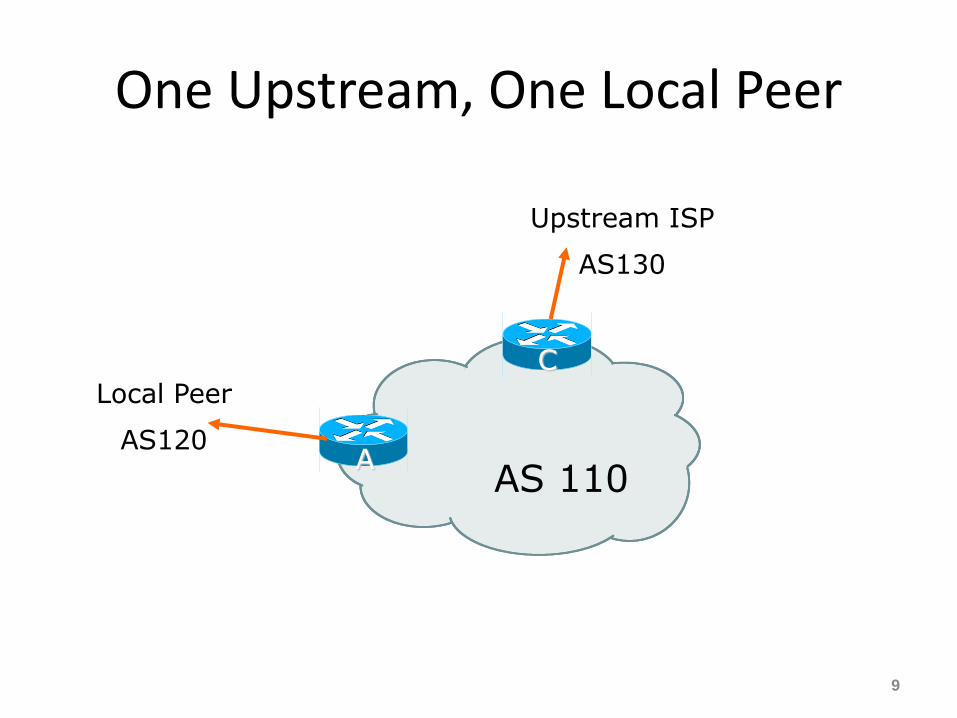
One Upstream, One Local Peer
• Very common situation in many regions of the Internet
• Connect to upstream transit provider to see the Internet
• Connect to the local competition so that local traffic stays local
– Saves spending valuable $ on upstream transit costs for local traffic
8
One Upstream, One Local Peer
9
AS 110
C
A
Upstream ISP
AS130
Local Peer
AS120

One Upstream, One Local Peer
• Announce /19 aggregate on each link
• Accept default route only from upstream
– Either 0.0.0.0/0 or a network which can be used as default
• Accept all routes the local peer originates
10
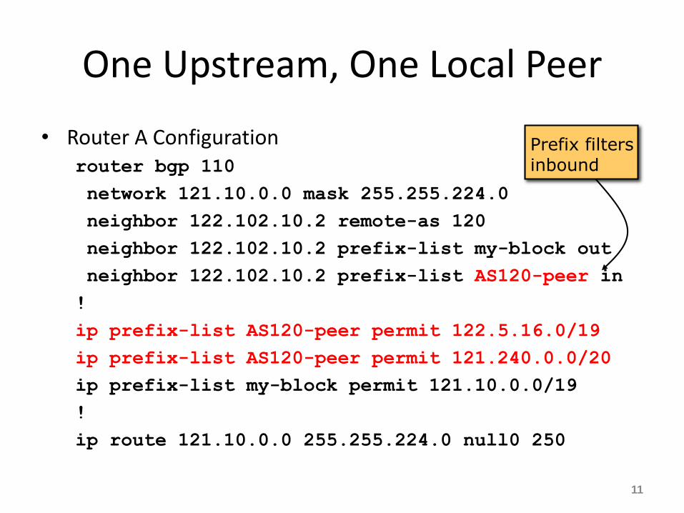
One Upstream, One Local Peer
• Router A Configurationrouter bgp 110
network 121.10.0.0 mask 255.255.224.0
neighbor 122.102.10.2 remote-as 120
neighbor 122.102.10.2 prefix-list my-block out
neighbor 122.102.10.2 prefix-list AS120-peer in
!
ip prefix-list AS120-peer permit 122.5.16.0/19
ip prefix-list AS120-peer permit 121.240.0.0/20
ip prefix-list my-block permit 121.10.0.0/19
!
ip route 121.10.0.0 255.255.224.0 null0 250
11
Prefix filtersinbound
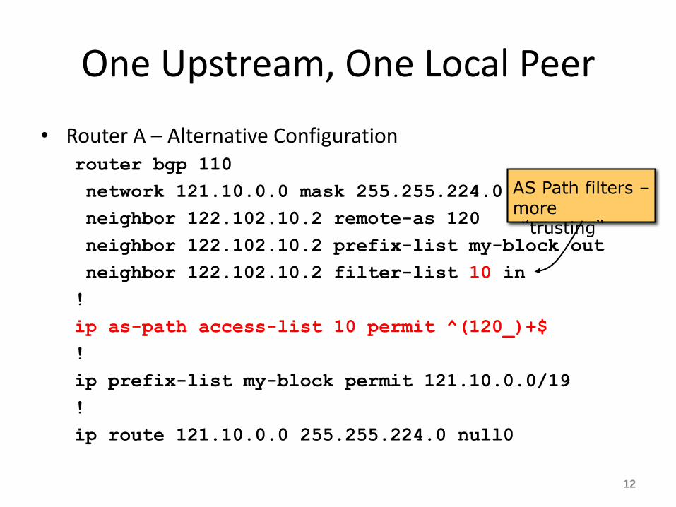
One Upstream, One Local Peer
• Router A – Alternative Configurationrouter bgp 110
network 121.10.0.0 mask 255.255.224.0
neighbor 122.102.10.2 remote-as 120
neighbor 122.102.10.2 prefix-list my-block out
neighbor 122.102.10.2 filter-list 10 in
!
ip as-path access-list 10 permit ^(120_)+$
!
ip prefix-list my-block permit 121.10.0.0/19
!
ip route 121.10.0.0 255.255.224.0 null0
12
AS Path filters –more
trusting

One Upstream, One Local Peer
• Router C Configurationrouter bgp 110
network 121.10.0.0 mask 255.255.224.0
neighbor 122.102.10.1 remote-as 130
neighbor 122.102.10.1 prefix-list default in
neighbor 122.102.10.1 prefix-list my-block out
!
ip prefix-list my-block permit 121.10.0.0/19
ip prefix-list default permit 0.0.0.0/0
!
ip route 121.10.0.0 255.255.224.0 null0
13

One Upstream, One Local Peer
• Two configurations possible for Router A
– Filter-lists assume peer knows what they are doing
– Prefix-list higher maintenance, but safer
– Some ISPs use both
• Local traffic goes to and from local peer, everything else goes to upstream
14
Aside: Configuration Recommendations
• Private Peers– The peering ISPs exchange prefixes they originate
– Sometimes they exchange prefixes from neighbouring ASNs too
• Be aware that the private peer eBGP router should carry only the prefixes you want the private peer to receive– Otherwise they could point a default route to you
and unintentionally transit your backbone
15

Service Provider Multihoming
One upstream, Local Exchange Point
16
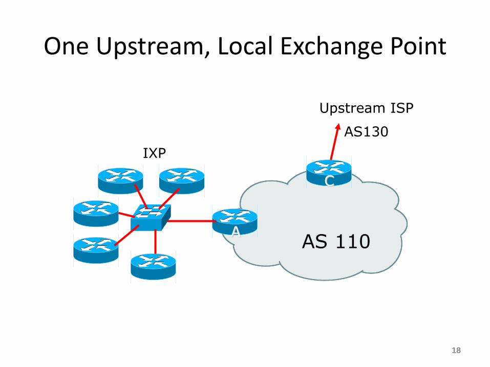
One Upstream, Local Exchange Point
• Very common situation in many regions of the Internet
• Connect to upstream transit provider to see the Internet
• Connect to the local Internet Exchange Point so that local traffic stays local– Saves spending valuable $ on upstream transit
costs for local traffic
• This example is a scaled up version of the previous one
17
One Upstream, Local Exchange Point
18
AS 110
C
A
Upstream ISP
AS130
IXP
One Upstream, Local Exchange Point
• Announce /19 aggregate to every neighbouring AS
• Accept default route only from upstream
– Either 0.0.0.0/0 or a network which can be used as default
• Accept all routes originated by IXP peers
19

One Upstream, Local Exchange Point
• Router A Configurationinterface fastethernet 0/0
description Exchange Point LAN
ip address 120.5.10.1 mask 255.255.255.224
!
router bgp 110
neighbor ixp-peers peer-group
neighbor ixp-peers prefix-list my-block out
neighbor ixp-peers remove-private-AS
neighbor ixp-peers send-community
neighbor ixp-peers route-map set-local-pref in
…next slide
20
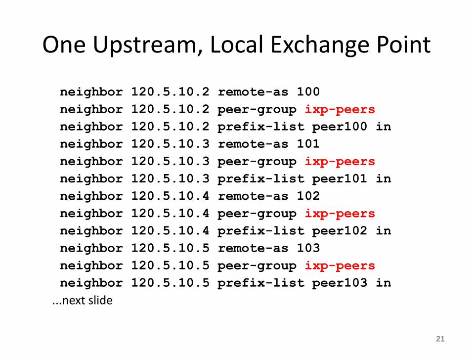
One Upstream, Local Exchange Point
neighbor 120.5.10.2 remote-as 100
neighbor 120.5.10.2 peer-group ixp-peers
neighbor 120.5.10.2 prefix-list peer100 in
neighbor 120.5.10.3 remote-as 101
neighbor 120.5.10.3 peer-group ixp-peers
neighbor 120.5.10.3 prefix-list peer101 in
neighbor 120.5.10.4 remote-as 102
neighbor 120.5.10.4 peer-group ixp-peers
neighbor 120.5.10.4 prefix-list peer102 in
neighbor 120.5.10.5 remote-as 103
neighbor 120.5.10.5 peer-group ixp-peers
neighbor 120.5.10.5 prefix-list peer103 in
...next slide
21

One Upstream, Local Exchange Point
!
ip prefix-list my-block permit 121.10.0.0/19
ip prefix-list peer100 permit 122.0.0.0/19
ip prefix-list peer101 permit 122.30.0.0/19
ip prefix-list peer102 permit 122.12.0.0/19
ip prefix-list peer103 permit 122.18.128.0/19
!
route-map set-local-pref permit 10
set local-preference 150
!
22

One Upstream, Local Exchange
• Note that Router A does not generate the aggregate for AS110– If Router A becomes disconnected from backbone, then the aggregate
is no longer announced to the IX
– BGP failover works as expected
• Note the inbound route-map which sets the local preference higher than the default– This is a visual reminder that BGP Best Path for local traffic will be
across the IXP
23
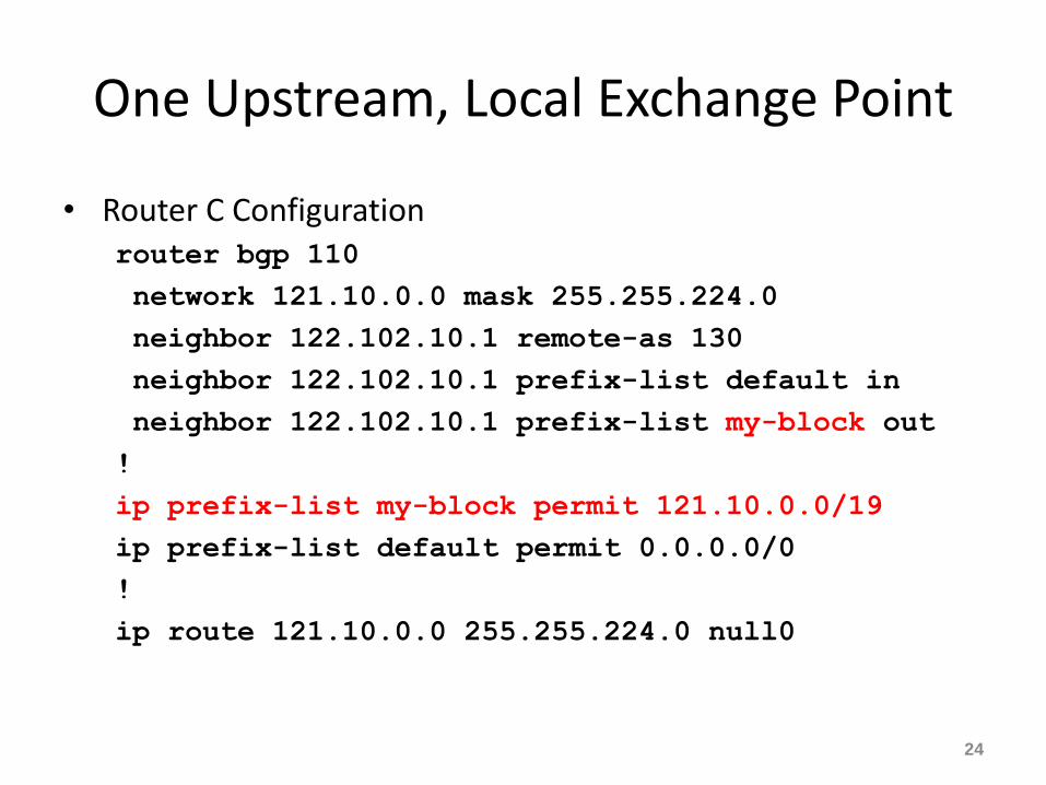
One Upstream, Local Exchange Point
• Router C Configurationrouter bgp 110
network 121.10.0.0 mask 255.255.224.0
neighbor 122.102.10.1 remote-as 130
neighbor 122.102.10.1 prefix-list default in
neighbor 122.102.10.1 prefix-list my-block out
!
ip prefix-list my-block permit 121.10.0.0/19
ip prefix-list default permit 0.0.0.0/0
!
ip route 121.10.0.0 255.255.224.0 null0
24

One Upstream, Local Exchange Point
• Note Router A configuration
– Prefix-list higher maintenance, but safer
– No generation of AS110 aggregate
• IXP traffic goes to and from local IXP, everything else goes to upstream
25
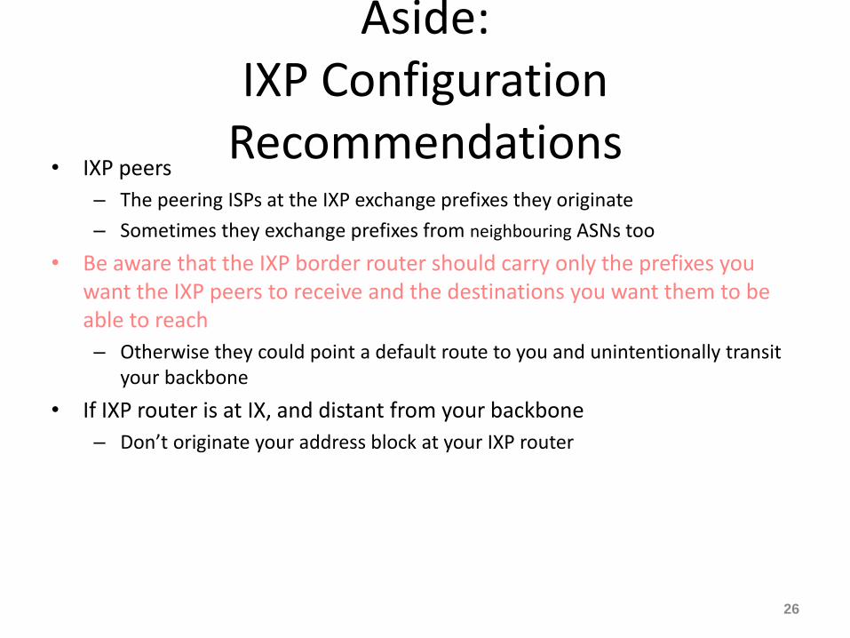
Aside: IXP Configuration
Recommendations• IXP peers
– The peering ISPs at the IXP exchange prefixes they originate
– Sometimes they exchange prefixes from neighbouring ASNs too
• Be aware that the IXP border router should carry only the prefixes you want the IXP peers to receive and the destinations you want them to be able to reach
– Otherwise they could point a default route to you and unintentionally transit your backbone
• If IXP router is at IX, and distant from your backbone
– Don’t originate your address block at your IXP router
26

Service Provider Multihoming
Two upstreams, one local peer
27
Two Upstreams, One Local Peer
• Connect to both upstream transit providers to see the Internet
– Provides external redundancy and diversity – the reason to multihome
• Connect to the local peer so that local traffic stays local
– Saves spending valuable $ on upstream transit costs for local traffic
28
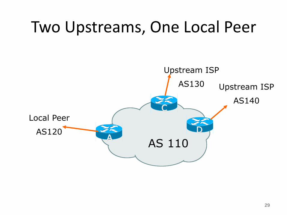
Two Upstreams, One Local Peer
29
AS 110
C
A
Upstream ISP
AS140
Local Peer
AS120 D
Upstream ISP
AS130

Two Upstreams, One Local Peer
• Announce /19 aggregate on each link
• Accept default route only from upstreams
– Either 0.0.0.0/0 or a network which can be used as default
• Accept all routes originated by local peer
• Note separation of Router C and D
– Single edge router means no redundancy
• Router A
– Same routing configuration as in example with one upstream and one local peer 30

Two Upstreams, One Local Peer
• Router C Configurationrouter bgp 110
network 121.10.0.0 mask 255.255.224.0
neighbor 122.102.10.1 remote-as 130
neighbor 122.102.10.1 prefix-list default in
neighbor 122.102.10.1 prefix-list my-block out
!
ip prefix-list my-block permit 121.10.0.0/19
ip prefix-list default permit 0.0.0.0/0
!
ip route 121.10.0.0 255.255.224.0 null0
31
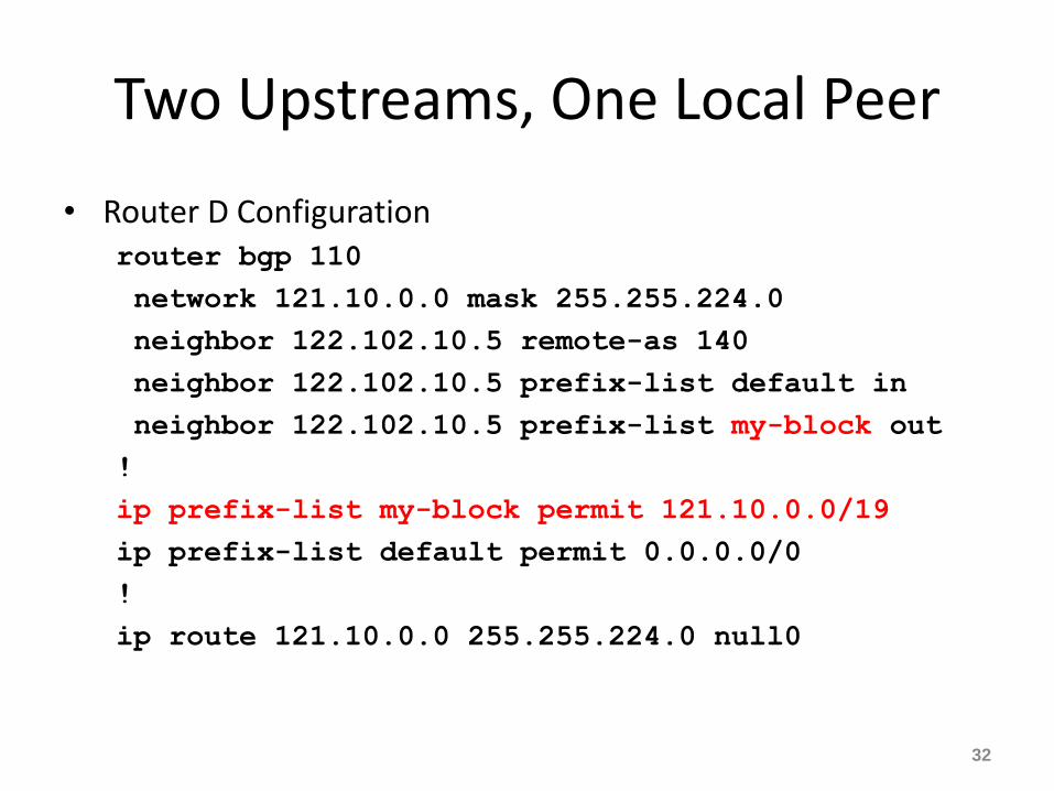
Two Upstreams, One Local Peer
• Router D Configurationrouter bgp 110
network 121.10.0.0 mask 255.255.224.0
neighbor 122.102.10.5 remote-as 140
neighbor 122.102.10.5 prefix-list default in
neighbor 122.102.10.5 prefix-list my-block out
!
ip prefix-list my-block permit 121.10.0.0/19
ip prefix-list default permit 0.0.0.0/0
!
ip route 121.10.0.0 255.255.224.0 null0
32
Two Upstreams, One Local Peer
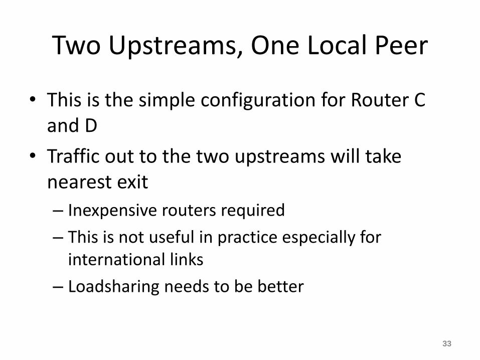
• This is the simple configuration for Router C and D
• Traffic out to the two upstreams will take nearest exit
– Inexpensive routers required
– This is not useful in practice especially for international links
– Loadsharing needs to be better
33
Two Upstreams, One Local Peer
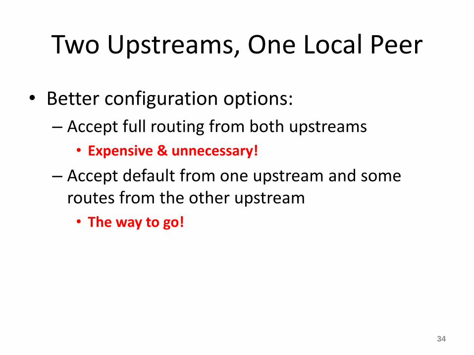
• Better configuration options:
– Accept full routing from both upstreams
• Expensive & unnecessary!
– Accept default from one upstream and some routes from the other upstream
• The way to go!
34
Two Upstreams, One Local PeerFull Routes
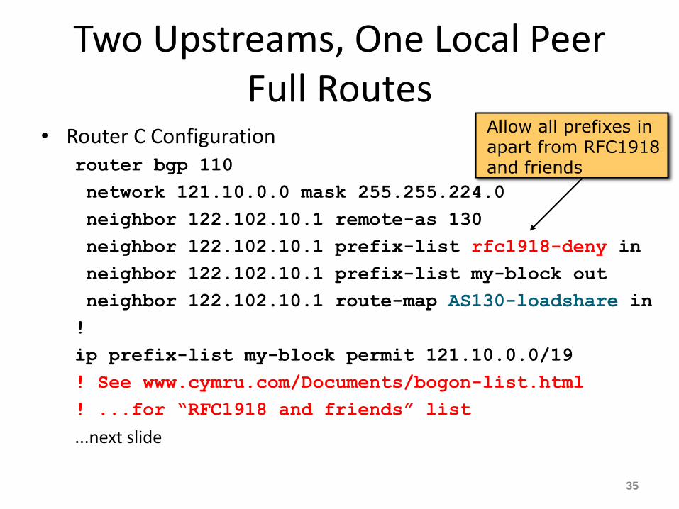
• Router C Configurationrouter bgp 110
network 121.10.0.0 mask 255.255.224.0
neighbor 122.102.10.1 remote-as 130
neighbor 122.102.10.1 prefix-list rfc1918-deny in
neighbor 122.102.10.1 prefix-list my-block out
neighbor 122.102.10.1 route-map AS130-loadshare in
!
ip prefix-list my-block permit 121.10.0.0/19
! See www.cymru.com/Documents/bogon-list.html
! ...for “RFC1918 and friends” list
...next slide
35
Allow all prefixes in apart from RFC1918 and friends

Two Upstreams, One Local PeerFull Routes
ip route 121.10.0.0 255.255.224.0 null0
!
ip as-path access-list 10 permit ^(130_)+$
ip as-path access-list 10 permit ^(130_)+_[0-9]+$
!
route-map AS130-loadshare permit 10
match ip as-path 10
set local-preference 120
!
route-map AS130-loadshare permit 20
set local-preference 80
!
36

Two Upstreams, One Local PeerFull Routes
• Router D Configurationrouter bgp 110
network 121.10.0.0 mask 255.255.224.0
neighbor 122.102.10.5 remote-as 140
neighbor 122.102.10.5 prefix-list rfc1918-deny in
neighbor 122.102.10.5 prefix-list my-block out
!
ip prefix-list my-block permit 121.10.0.0/19
! See www.cymru.com/Documents/bogon-list.html
! ...for “RFC1918 and friends” list
37
Allow all prefixes in apart from RFC1918 and friends

Two Upstreams, One Local PeerFull Routes
• Router C configuration:
– Accept full routes from AS130
– Tag prefixes originated by AS130 and AS130’s neighbouring ASes with local preference 120
• Traffic to those ASes will go over AS130 link
– Remaining prefixes tagged with local preference of 80
• Traffic to other all other ASes will go over the link to AS140
• Router D configuration same as Router C without the route-map 38

Two Upstreams, One Local PeerFull Routes
• Full routes from upstreams
– Expensive – needs lots of memory and CPU
– Need to play preference games
– Previous example is only an example – real life will need improved fine-tuning!
– Previous example doesn’t consider inbound traffic – see earlier in presentation for examples
39

Two Upstreams, One Local PeerPartial Routes: Strategy
• Ask one upstream for a default route
– Easy to originate default towards a BGP neighbour
• Ask other upstream for a full routing table
– Then filter this routing table based on neighbouring ASN
– E.g. want traffic to their neighbours to go over the link to that ASN
– Most of what upstream sends is thrown away
– Easier than asking the upstream to set up custom BGP filters for you
40
Two Upstreams, One Local PeerPartial Routes
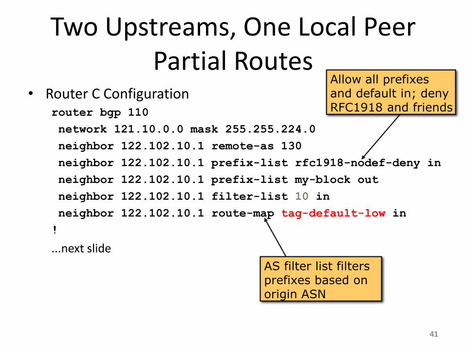
• Router C Configurationrouter bgp 110
network 121.10.0.0 mask 255.255.224.0
neighbor 122.102.10.1 remote-as 130
neighbor 122.102.10.1 prefix-list rfc1918-nodef-deny in
neighbor 122.102.10.1 prefix-list my-block out
neighbor 122.102.10.1 filter-list 10 in
neighbor 122.102.10.1 route-map tag-default-low in
!
...next slide
41
Allow all prefixes and default in; deny RFC1918 and friends
AS filter list filters prefixes based on origin ASN

Two Upstreams, One Local PeerPartial Routes
ip prefix-list my-block permit 121.10.0.0/19
ip prefix-list default permit 0.0.0.0/0
!
ip route 121.10.0.0 255.255.224.0 null0
!
ip as-path access-list 10 permit ^(130_)+$
ip as-path access-list 10 permit ^(130_)+_[0-9]+$
!
route-map tag-default-low permit 10
match ip address prefix-list default
set local-preference 80
!
route-map tag-default-low permit 20
!
42

Two Upstreams, One Local PeerPartial Routes
• Router D Configurationrouter bgp 110
network 121.10.0.0 mask 255.255.224.0
neighbor 122.102.10.5 remote-as 140
neighbor 122.102.10.5 prefix-list default in
neighbor 122.102.10.5 prefix-list my-block out
!
ip prefix-list my-block permit 121.10.0.0/19
ip prefix-list default permit 0.0.0.0/0
!
ip route 121.10.0.0 255.255.224.0 null0
43

Two Upstreams, One Local PeerPartial Routes
• Router C configuration:
– Accept full routes from AS130
• (or get them to send less)
– Filter ASNs so only AS130 and AS130’s neighbouring ASes are accepted
– Allow default, and set it to local preference 80
– Traffic to those ASes will go over AS130 link
– Traffic to other all other ASes will go over the link to AS140
– If AS140 link fails, backup via AS130 – and vice-versa
44

Two Upstreams, One Local PeerPartial Routes
• Router C IGP Configurationrouter ospf 110
default-information originate metric 30
passive-interface Serial 0/0
!
ip route 0.0.0.0 0.0.0.0 serial 0/0 254
• Router D IGP Configurationrouter ospf 110
default-information originate metric 10
passive-interface Serial 0/0
!
ip route 0.0.0.0 0.0.0.0 serial 0/0 254

Two Upstreams, One Local PeerPartial Routes
• Partial routes from upstreams
– Use OSPF to determine outbound path
– Router D default has metric 10 – primary outbound path
– Router C default has metric 30 – backup outbound path
– Serial interface goes down, static default is removed from routing table, OSPF default withdrawn
Two Upstreams, One Local PeerPartial Routes
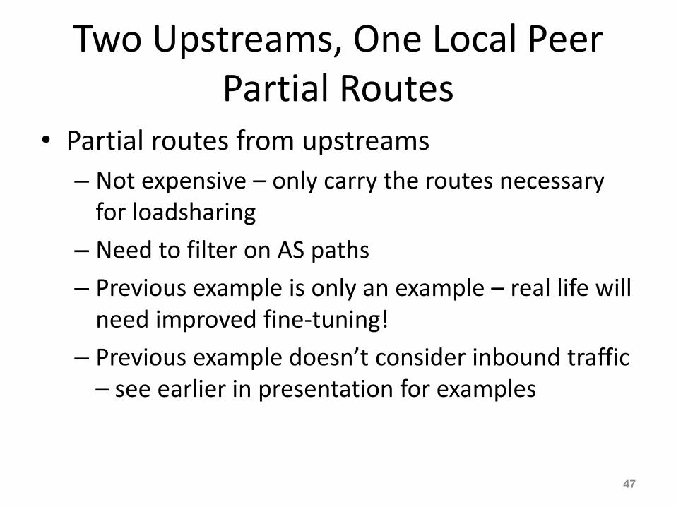
• Partial routes from upstreams
– Not expensive – only carry the routes necessary for loadsharing
– Need to filter on AS paths
– Previous example is only an example – real life will need improved fine-tuning!
– Previous example doesn’t consider inbound traffic – see earlier in presentation for examples
47

Aside: Configuration Recommendation
• When distributing internal default by iBGP or OSPF/ISIS
– Make sure that routers connecting to private peers or to IXPs do NOT carry the default route
– Otherwise they could point a default route to you and unintentionally transit your backbone
– Simple fix for Private Peer/IXP routers:
ip route 0.0.0.0 0.0.0.0 null0
48
Service Provider Multihoming
Three upstreams, unequal bandwidths
49

Three upstreams, unequal bandwidths
• Autonomous System has three upstreams– 16Mbps to ISP A
– 8Mbps to ISP B
– 4Mbps to ISP C
• What is the strategy here?– One option is full table from each
• 3x 400k prefixes 1200k paths
– Other option is partial table and defaults from each• How??
50

Strategy
• Two external routers (gives router redundancy)– Do NOT need three routers for this
• Connect biggest bandwidth to one router– Most of inbound and outbound traffic will go here
• Connect the other two links to the second router– Provides maximum backup capacity if primary link fails
• Use the biggest link as default– Most of the inbound and outbound traffic will go here
• Do the traffic engineering on the two smaller links– Focus on regional traffic needs
51
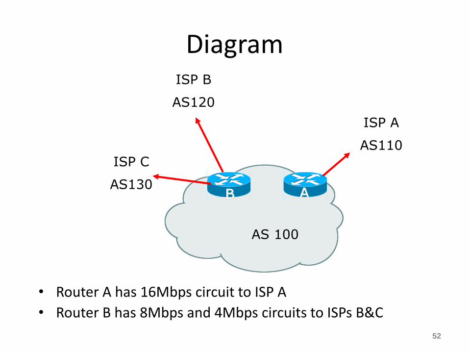
Diagram
• Router A has 16Mbps circuit to ISP A
• Router B has 8Mbps and 4Mbps circuits to ISPs B&C
52
AS 100
B
ISP A
AS110
ISP C
AS130A
ISP B
AS120
Outbound load-balancing strategy
• Available BGP feeds from Transit providers:– Full table
– Customer prefixes and default
– Default Route
• These are the common options on Internet today– Very rare for any provider to offer anything
different
– Very rare for any provider to customise BGP feed for a customer
53

Outbound load-balancing strategy
• Accept only a default route from the provider with the largestconnectivity, ISP A– Because most of the traffic is going to use this link
• If ISP A won t provide a default:– Still run BGP with them, but discard all prefixes
– Point static default route to the upstream link
– Distribute the default in the IGP
• Request the full table from ISP B & C– Most of this will be thrown away
– ( Default plus customers is not enough)
54
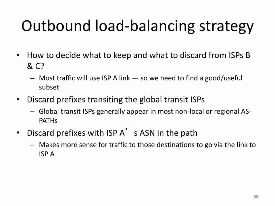
Outbound load-balancing strategy
• How to decide what to keep and what to discard from ISPs B & C?– Most traffic will use ISP A link — so we need to find a good/useful
subset
• Discard prefixes transiting the global transit ISPs– Global transit ISPs generally appear in most non-local or regional AS-
PATHs
• Discard prefixes with ISP A s ASN in the path– Makes more sense for traffic to those destinations to go via the link to
ISP A
55
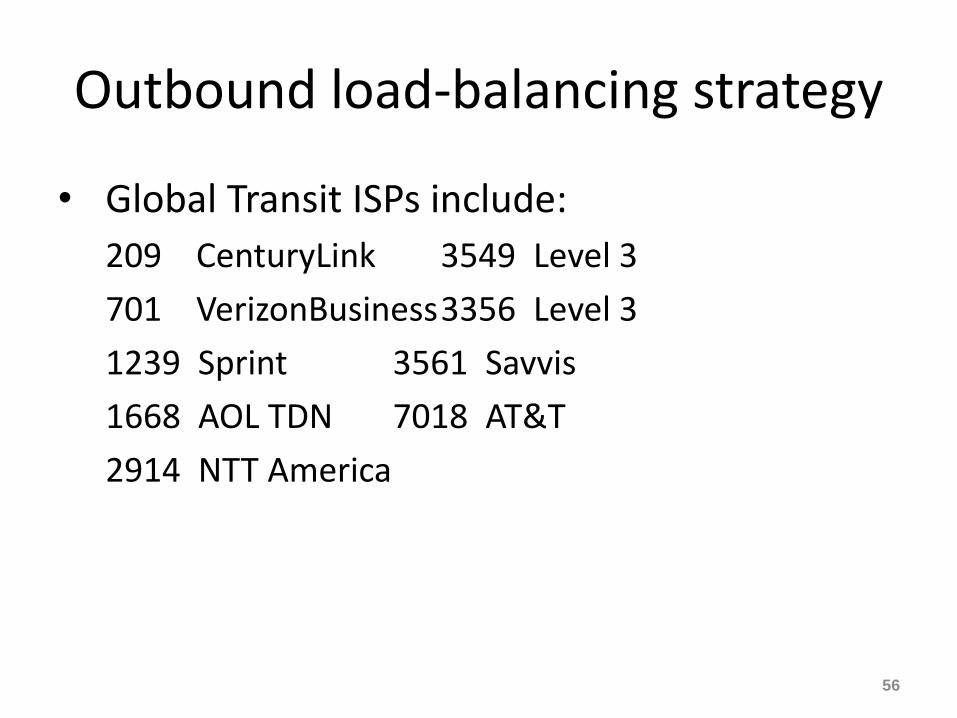
Outbound load-balancing strategy
• Global Transit ISPs include:
209 CenturyLink 3549 Level 3
701 VerizonBusiness3356 Level 3
1239 Sprint 3561 Savvis
1668 AOL TDN 7018 AT&T
2914 NTT America
56

ISP B peering Inbound AS-PATH filter
ip as-path access-list 1 deny _209_
ip as-path access-list 1 deny _701_
ip as-path access-list 1 deny _1239_
ip as-path access-list 1 deny _3356_
ip as-path access-list 1 deny _3549_
ip as-path access-list 1 deny _3561_
ip as-path access-list 1 deny _2914_
ip as-path access-list 1 deny _7018_
!
ip as-path access-list 1 deny _ISPA_
ip as-path access-list 1 deny _ISPC_
!
ip as-path access-list 1 permit _ISPB$
ip as-path access-list 1 permit _ISPB_[0-9]+$
ip as-path access-list 1 permit _ISPB_[0-9]+_[0-9]+$
ip as-path access-list 1 permit _ISPB_[0-9]+_[0-9]+_[0-9]+$
ip as-path access-list 1 deny .*57
Don t need ISPA and
ISPC prefixes via ISPB
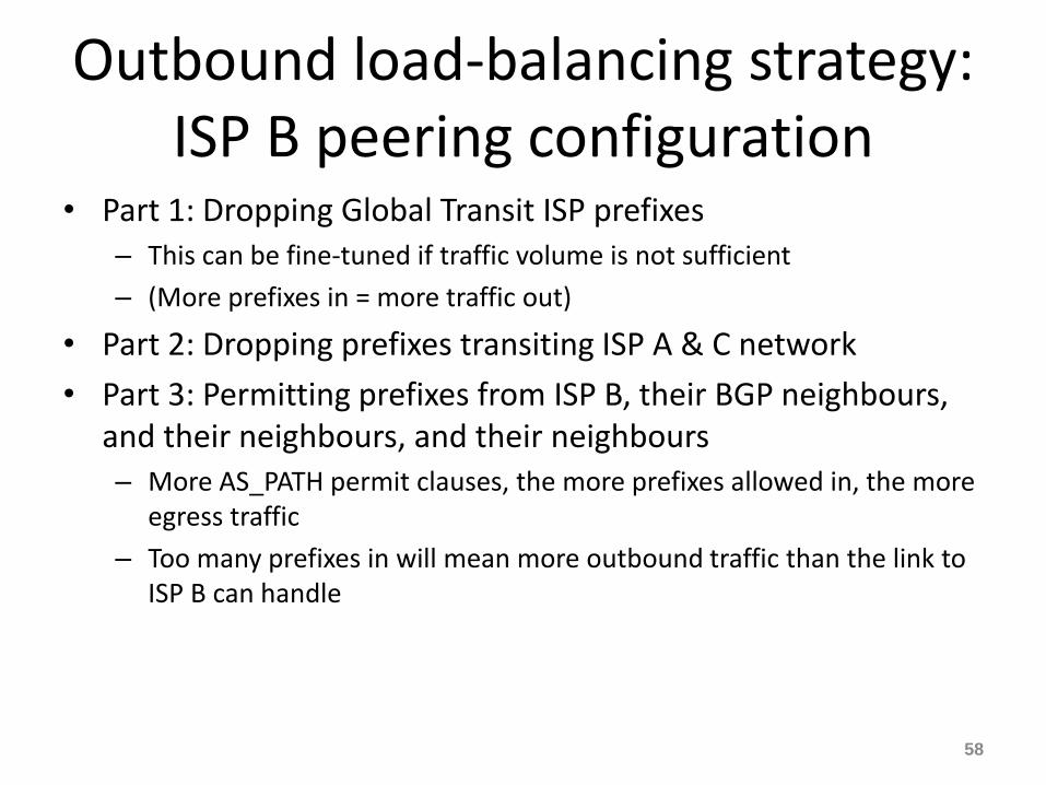
Outbound load-balancing strategy:ISP B peering configuration
• Part 1: Dropping Global Transit ISP prefixes– This can be fine-tuned if traffic volume is not sufficient
– (More prefixes in = more traffic out)
• Part 2: Dropping prefixes transiting ISP A & C network
• Part 3: Permitting prefixes from ISP B, their BGP neighbours, and their neighbours, and their neighbours– More AS_PATH permit clauses, the more prefixes allowed in, the more
egress traffic
– Too many prefixes in will mean more outbound traffic than the link to ISP B can handle
58

Outbound load-balancing strategy
• Similar AS-PATH filter can be built for the ISP C BGP peering
• If the same prefixes are heard from both ISP B and C, then establish proximity of their origin ASN to ISP B or C
– e.g. ISP B might be in Japan, with the neighbouring ASN in Europe, yet ISP C might be in Europe
– Transit to the ASN via ISP C makes more sense in this case
59

Inbound load-balancing strategy
• The largest outbound link should announce just the aggregate
• The other links should announce:a) The aggregate with AS-PATH prepend
b) Subprefixes of the aggregate, chosen according to traffic volumes to those subprefixes, and according to the services on those subprefixes
• Example:– Link to ISP B could be used just for Broadband/Dial customers — so
number all such customers out of one contiguous subprefix
– Link to ISP C could be used just for commercial leased line customers — so number all such customers out of one contiguous subprefix
60
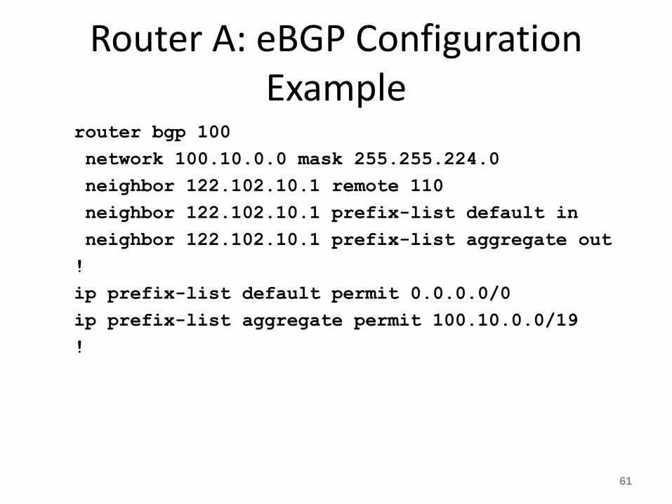
Router A: eBGP Configuration Example
router bgp 100
network 100.10.0.0 mask 255.255.224.0
neighbor 122.102.10.1 remote 110
neighbor 122.102.10.1 prefix-list default in
neighbor 122.102.10.1 prefix-list aggregate out
!
ip prefix-list default permit 0.0.0.0/0
ip prefix-list aggregate permit 100.10.0.0/19
!
61

Router B: eBGP Configuration Example
router bgp 100
network 100.10.0.0 mask 255.255.224.0
neighbor 120.103.1.1 remote 120
neighbor 120.103.1.1 filter-list 1 in
neighbor 120.103.1.1 prefix-list ISP-B out
neighbor 120.103.1.1 route-map to-ISP-B out
neighbor 121.105.2.1 remote 130
neighbor 121.105.2.1 filter-list 2 in
neighbor 121.105.2.1 prefix-list ISP-C out
neighbor 121.105.2.1 route-map to-ISP-C out
!
ip prefix-list aggregate permit 100.10.0.0/19
!
...next slide
62
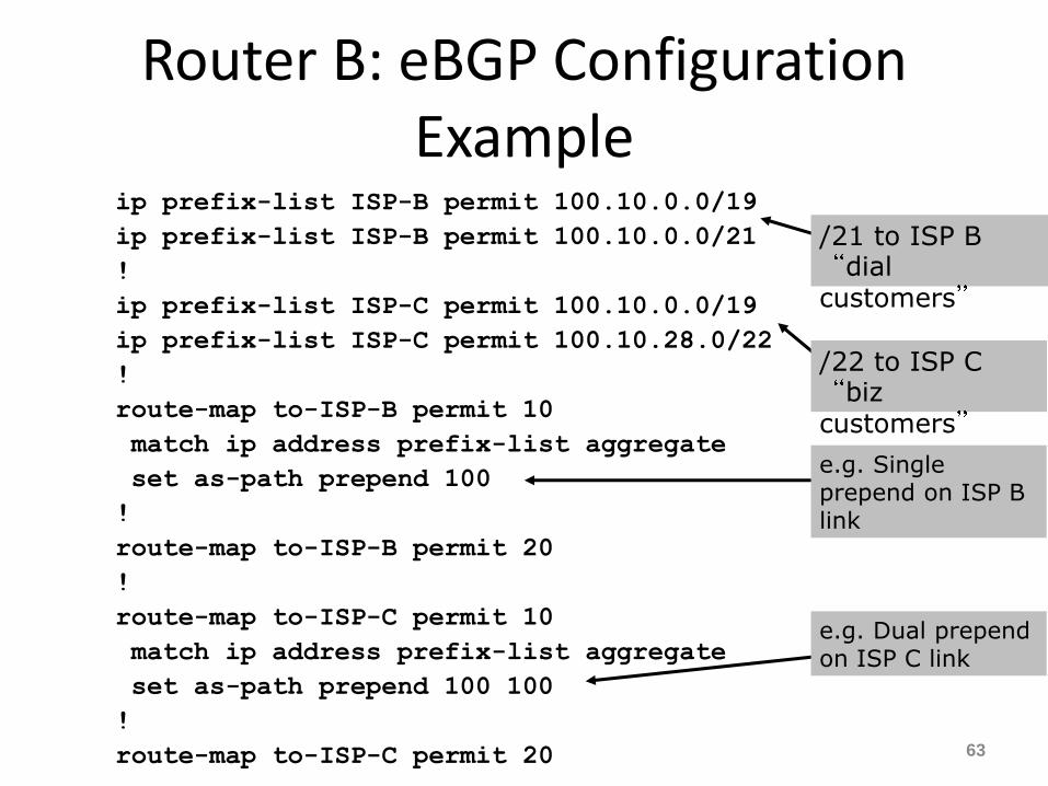
Router B: eBGP Configuration Example
ip prefix-list ISP-B permit 100.10.0.0/19
ip prefix-list ISP-B permit 100.10.0.0/21
!
ip prefix-list ISP-C permit 100.10.0.0/19
ip prefix-list ISP-C permit 100.10.28.0/22
!
route-map to-ISP-B permit 10
match ip address prefix-list aggregate
set as-path prepend 100
!
route-map to-ISP-B permit 20
!
route-map to-ISP-C permit 10
match ip address prefix-list aggregate
set as-path prepend 100 100
!
route-map to-ISP-C permit 20 63
/21 to ISP Bdial
customers
e.g. Single prepend on ISP B link
/22 to ISP Cbiz
customers
e.g. Dual prepend on ISP C link

What about outbound backup?
• We have:– Default route from ISP A by eBGP
– Mostly discarded full table from ISPs B&C
• Strategy:– Originate default route by OSPF on Router A (with metric 10) — link to
ISP A
– Originate default route by OSPF on Router B (with metric 30) — links to ISPs B & C
– Plus on Router B:
• Static default route to ISP B with distance 240
• Static default route to ISP C with distance 245
– When link goes down, static route is withdrawn
64

Outbound backup: steady state
• Steady state (all links up and active):
– Default route is to Router A — OSPF metric 10
– (Because default learned by eBGP default is in RIB OSPF will originate default)
– Backup default is to Router B — OSPF metric 20
– eBGP prefixes learned from upstreams distributed by iBGP throughout backbone
– (Default can be filtered in iBGP to avoid RIB failure error )
65

Outbound backup: failure examples
• Link to ISP A down, to ISPs B&C up:– Default route is to Router B — OSPF metric 20
– (eBGP default gone from RIB, so OSPF on Router A withdraws the default)
• Above is true if link to B or C is down as well
• Link to ISPs B & C down, link to ISP A is up:– Default route is to Router A — OSPF metric 10
– (static defaults on Router B removed from RIB, so OSPF on Router B withdraws the default)
66

Other considerations
• Default route should not be propagated to devices terminating non-transit peers and customers
• Rarely any need to carry default in iBGP
– Best to filter out default in iBGP mesh peerings
• Still carry other eBGP prefixes across iBGP mesh
– Otherwise routers will follow default route rules resulting in suboptimal traffic flow
– Not a big issue because not carrying full table 67
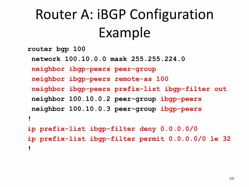
Router A: iBGP Configuration Example
router bgp 100
network 100.10.0.0 mask 255.255.224.0
neighbor ibgp-peers peer-group
neighbor ibgp-peers remote-as 100
neighbor ibgp-peers prefix-list ibgp-filter out
neighbor 100.10.0.2 peer-group ibgp-peers
neighbor 100.10.0.3 peer-group ibgp-peers
!
ip prefix-list ibgp-filter deny 0.0.0.0/0
ip prefix-list ibgp-filter permit 0.0.0.0/0 le 32
!
68
Three upstreams, unequal bandwidths:
Summary• Example based on many deployed working
multihoming/loadbalancing topologies
• Many variations possible — this one is:
– Easy to tune
– Light on border router resources
– Light on backbone router infrastructure
– Sparse BGP table faster convergence
69

Acknowledgement and Attribution
This presentation contains content and information
originally developed and maintained by the following
organisation(s)/individual(s) and provided for the
African Union AXIS Project
Philip Smith: - [email protected]
Cisco ISP/IXP Workshops
www.apnic.net

Advanced Multihoming
End
71