bfsh2supplementsxdraft6 · proposed draft 5 6 3 nb10-0601 or degradation should not have any...
TRANSCRIPT

Proposed Draft 5 6
1
NB10-0601
SUPPLEMENT 9
INSPECTION OF STATIONARY HIGH PRESSURE
(3000-15000 psi) COMPOSITE PRESSURE
VESSELS
S9.1 SCOPE
This supplement provides specific guidelines for inspection of high pressure composite pressure vessels. This supplement is applicable to pressure vessels with a design pressure that exceeds 3000 psi but no greater than 15000 psi, and is applicable to the following four classes of pressure vessels:
a) Metallic vessel with a hoop Fiber Reinforced Plastic (FRP) wrap over the straight shell cylindrical part of the vessel (both load sharing). b) Fully wrapped FRP vessel with a non-load sharing metallic liner. c) FRP vessel with a non-load sharing non-metallic liner. d) Fully wrapped FRP vessel with load sharing metallic liner.
S9.2 INSERVICE INSPECTION
a) Section 1 of this Part shall apply to inspection of high pressure composite pressure vessels, except as modified herein. This supplement covers composite vessels and tanks only, and was not written to cover piping and ductwork, although some of the information in this supplement may be used for the inspection of piping and ductwork. b) The inspection and testing for exposed load sharing metallic portions of composite pressure vessels shall be in accordance with Part 2, Section 2.3 and 4 of this Code. c. All composite vessels shall have an initial acoustic emission examination per S9.11 after the first 3 years from the date of manufacture. Thereafter, composite vessels shall have a maximum examination interval of 5 years which shall be shortened based on the results of any external inspection per paragraph S9.7.
Proposed Draft 5 6
2
NB10-0601
d. All composite vessels shall be subject to the periodic inspection frequency given in S9.9.
S9.3 GENERAL
a) High pressure composite vessels are used for the storage of hydrogen and other gases fluids at pressures up to 15000 psi. Composite vessels consist of the FRP laminate with load sharing or non load sharing metallic shells/liners, or non metallic liners. The FRP laminate with load sharing metallic liners form the pressure retaining system. The FRP laminate is the pressure retaining material for composite vessels with non-load sharing metallic and non metallic liners. The purpose of the non-load sharing metallic and the non metallic liners is to minimize the permeation of hydrogen fluids through the vessel wall. b) The hydrogen gas stored in the composite vessels is 99.9999% pure, and is Fluids stored in composite vessels are considered to be non corrosive to the materials used for vessel construction. The laminate is susceptible to damage from:
1) External Chemical attack 2) External Mechanical damage(i.e. abrasion, impact,
cuts, dents, etc.) 3) Structural damage (i.e. over pressurization,
distortion, bulging, etc.) 4) Environmental degradation [i.e. ultraviolet (if there
is no pigmented coating or protective layer), ice, etc.]
5) Fire or excessive heat S9.4 VISUAL EXAMINATION
a) Acceptable Damage
Acceptable damage or degradation is minor and is normally found in service and is considered to be cosmetic. This level of damage or degradation does not reduce the structural integrity of the tank composite vessel. This level of damage

Proposed Draft 5 6
3
NB10-0601
or degradation should not have any adverse effect on the continued safe use of the tank. This level of damage or degradation does not require any repair to be performed at the time of in-service inspection. When there is an external, non load bearing, sacrificial layer of filaments on the tank vessel, any damage or degradation should be limited to this layer. There should be no evidence of any cut filaments in the structural wall Damage or degradation of the structural wall shall not exceed the limits specified in Table 1.
b) Rejectable Damage (Condemned—Not Repairable)
Rejectable damage or degradation is so severe that structural integrity of the tank is sufficiently reduced so that the tank composite vessel is considered unfit for continued service and must be condemned and removed from service. No repair is authorized for tanks composite vessels with rejectable damage or degradation.
c) Acceptance Criteria
Certain, specific types of damage can be identified by the external in-service visual inspection. Indications of certain types and sizes may not significantly reduce the structural integrity of the tanks composite vessel and may be acceptable so that the tanks composite vessel can be left in service. Other types and larger sizes of damages may reduce the structural integrity of the tanks composite vessel and the tanks composite vessel must be condemned and removed from service. Table 1 table is a summary of the acceptance/rejection criteria for the indications that are found by external visual inspection of the tanks composite vessel.
d) Fitness-for-service
1) If a visual inspection reveals that a hydrogen cylinder composite vessel does not meet all criteria of Table 1 satisfactorily, it shall be taken out of service immediately and either be condemned or a fitness-for-service examination be conducted by the original vessel

Proposed Draft 5 6
4
NB10-0601
manufacturer who must also hold a National Board R stamp certificate. When the composite vessel is taken out of service, its contents must be immediately safely vented or transferred to another storage vessel per the owner's written safety procedures.
2) If a fitness-for-service examination is to be conducted, the original hydrogen cylinder composite vessel manufacturer shall be contacted as soon as possible after the rejectable defects have been found. The manufacturer shall then determine the cylinder's composite vessel fitness-for-service by applicable techniques, i.e., acoustic emission testing, ultra-sonic testing, and/or other feasible methods. The manufacturer shall have documentation that the evaluation method(s) used is satisfactory for determining the condition of the cylinder composite vessel. and whether repairs are feasible for any permissible structural defects. All repairs to the structural laminate shall only be made by the original manufacturer. Repairs to the outer protective layer may be made by a R stamp certificate holder other than the original manufacturer following the original manufacturer's instructions.
Table 1 - Visual Acceptance/ Rejection Criteria for Composite Pressure Vessels
Type of Degradation or Damage
Description of Degradation or Damage Acceptable Level of Degradation or
Damage
Rejectable Level of Degradation
or Damage
Abrasion Abrasion is damage to the filaments caused by wearing or rubbing of the
surface by friction
Less than 0.050 in. depth in the pressure bearing
thickness.
> 0.050 in. depth in the
pressure bearing thickness
Cuts Linear indications flaws caused by a impact with a sharp object
Less than 0.050 in. depth in the pressure bearing
thickness.
> 0.050 in. depth in the
pressure bearing thickness

Proposed Draft 5 6
5
Impact Damage Damage to the tank caused by striking the tank with an object or
by being dropped. This may be indicated by discoloration of the
composite or broken filaments and/or cracking.
Slight damage that causes a
frosted appearance or
hairline cracking of the resin in the impact area
Any permanent deformation of the tank or
damaged filaments
Delamination Lifting or separation of the filaments due to impact, a cut, or
fabrication error.
Minor delamination of the exterior
coating
Any loose filament ends showing on the surface. Any
bulging due to interior
delaminations
Heat or Fire Damage Discoloration, charring or distortion of the composite due to
temperatures beyond the curing temperature of the composite
Merely soiled by soot or other
debris, such that the cylinder can be washed with no
residue
Any evidence of thermal
degradation or discoloration or
distortion
Structural Damage – bulging, distortion,
depressions
Change in shape of the tank due to sever impact or dropping
None Any visible distortion, bulging, or depression
Chemical attack Environmental exposure that causes a change in the composite or failure
of the filaments
Any attack that can be cleaned off and that
leaves no residue
Any permanent discoloration or
loss or softening of
material under the exterior
coat.
Cracks Sharp, linear indications None None
Scratches/Gouges Sharp, linear indications caused by mechanical damage.
Less than 0.050 in. depth in the pressure bearing
thickness No structural fibers cut or
broken
> 0.050 in. depth in the
pressure bearing thickness or structural
fibers cut or broken
Soot A deposit on the composite caused by thermal or environmental exposure
Soot that washes off and leaves no
residue
Any permanent marking that will not wash
off the surface under the
exterior coating
Over pressurization Excessive pressure due to operational malfunction
None reported Any report of pressurization beyond the MAWP
or any indication of distortion

Proposed Draft 5 6
6
Corrosion Degradation of the composite due to exposure to specific corrosive
environments
None visible Any surface damage to structural
identified as corrosion
Dents A depression in the exterior of the tank caused by impact or dropping
< 1/16 in. in depth
Any dents with a depth > 1/16 in.
Or with a diameter greater than 2 inches
Reported collision, accident, or fire
Damage to the tank caused by unanticipated excursion from normally expected operating
conditions
None reported Any indication or report of
impact or heat damage
Environmental Damage or Weathering
Ultraviolet or other environmental attack under the exterior coating.
None Any discoloration
that can not be washed off*
Crazing Hairline surface cracks only in the composite resin
Light hairline cracks only in
the resin
Any damage to the filaments
Damage to a protective or
sacrificial layer
Abrasion, cuts, chemical attack, scratches/gouges, corrosion,
environmental damage, or crazing that are limited only to the
protective or sacrificial layer.
The depth of any damage to the protective or
sacrificial layer that does not exceed the
thickness of the protective or
sacrificial layer plus 0.050 inch.
The depth of any damage to the protective or sacrificial layer that exceeds the
thickness of the protective or sacrificial
layer plus 0.050 inch.
Note: Only damage beyond the sacrificial or coated layer should be considered, and that any damage to sacrificial or coated layers should be repaired by suitable techniques (i.e. epoxy filler). Refer to ASME data report for sacrificial layer thickness.
* - Washing off UV scale will accelerate attack into lower composite layers. For this reason, if there is superficial UV damage we recommend persons the affected area should be to cleaned and painted the affected area with a UV tolerant paint. If broken, frayed, or separated fibers, to the non sacrificial layer, are discovered during the cleaning process then the cylinder vessel must shall be condemned.
S9.5 INSPECTOR QUALIFICATIONS The Inspector shall be familiar with composite tank construction and qualified by training and experience to conduct such inspections. The Inspector should have a thorough understanding of all required inspections, tests, test apparatus, inspection procedures, and inspection techniques and equipment applicable to the types of tanks vessels to be inspected. The Inspector

Proposed Draft 5 6
7
NB10-0601
should have basic knowledge of the container vessel material types and properties. Refer to Part 2 para. S4.2 The acoustic emission technician conducting the examination required per S9.2(c) and in accordance with S9.11 shall be certified per the guidelines of ASNT SNT-TC-1A or CP-189 AE Level II or III. A technician performing this test should shall have training in and experience with measuring Ce and Cf in composites and identifying wave modes. S9.6 ASSESSMENT OF INSTALLATION
a) The visual examination of the tanks composite vessel requires that all exposed surfaces of the tank vessel are examined to identify any degradation, defects, mechanical damage, or environmental damage on the surface of the tank vessel. The causes of damage to the tanks composite vessels that may be found are: (1) abrasion damage, (2) cut damage, (3) impact damage, (4) structural damage, (5) chemical or environmental exposure damage or degradation, and (6) heat or fire damage. The types of damage found are: (1) cracks, (2) discolored areas, (3) gouges and impact damage, (4) leaks, (5) fiber exposure, (6) blisters, (7) delaminations, (8) surface degradation, and (9) broken tank supports.
b) The visual examination of the tanks tank composite vessels requires that the identity of the tank vessel must be verified. This should include the ASME Code to which the tank vessel was constructed, the tank vessel serial number, the maximum allowed operating pressure, the date of manufacture, the tank vessel manufacturer, the date of expiration of the service life of the tank vessel, and any other pertinent information shown on the tank vessel or available from tank vessel documents. The overall condition of the tank composite vessel should be noted.

Proposed Draft 5 6
8
NB10-0601
S9.7 EXTERNAL INSPECTION
a) Tank Service Life
Composite tanks vessels have been designed and manufactured for a limited lifetime; this is indicated on the tank vessel marking. This marking should first be checked to ensure that such tanks vessels are within their designated service lifetime.
b) Identification of External Damage
The external surface should be inspected for damage to the composite laminate. Any dDamage is classified into two levels of damage as shown in Section 9 of these guidelines. The acceptance/rejection criteria shown in section 10 of these guidelines should be followed, as a minimum. The external surface of the tank vessel is subject to mechanical, thermal, and environmental damage. The external surface of the tank a composite vessel may show damage from impacts, gouging, abrasion, scratching, temperature excursions, etc. Areas of the surface that are exposed to sunlight may be degraded by ultraviolet light which results in change in the color of the surface and may make the fibers more visible. This discoloration does not indicate a loss in physical properties of the fibers. Overheating may also cause a change in color. The size (area or length and depth) and location of all external damage should be noted. Tank Composite vessel support structures and attachments should be examined for damage such as cracks, deformation, or structural failure.
c) Types of External Damage
1. General
Several types of damage to the exterior of composite tanks vessels have been identified. Examples of specific type of damage are described below. The acceptance/rejection

Proposed Draft 5 6
9
NB10-0601
criteria for each type of damage are described in Table 1 of this supplement.
2. Abrasion Damage
Abrasion damage is caused by grinding or rubbing away of the exterior of the tank composite vessel. Minor abrasion damage to the protective outer coating or paint will not reduce the structural integrity of the tank vessel. Abrasion that results in flat spots on the surface of the tank vessel may indicate loss of composite fiber overwrap thickness
3. Damage from Cuts
Cuts or gouges are caused by contact with sharp objects in such a way as to cut into the composite overwrap, reducing its thickness at that point.
4. Impact Damage
Impact damage may appear as hairline cracks in the resin, delamination, or cuts of the composite fiber overwrap.
5. Delamination
Delamination is a separation of layers of fibers of the composite overwrap. It may also appear as a discoloration or a blister beneath the surface of the fiber.
6. Heat or Fire Damage
Heat or fire damage may be evident by discoloration, charring or burning of the composite fiber overwrap, labels, or paint. If there is any suspicion of damage, the vessel shall be re-qualified using an acoustic emission examination.
7. Structural Damage
Structural damage will be evidenced by bulging, distortion, or depressions on the surface of the tank vessel.
Proposed Draft 5 6
10
NB10-0601
8. Chemical Attack
Some chemicals are known to cause damage to composite materials. Environmental exposure or direct contact with solvents, acids, bases, alcohols, and general corrosives can cause damage to composite tanks vessels. Long-term contact with water can also contribute to corrosive damage. Chemicals can dissolve, corrode, remove, or destroy tank materials. Chemical attack can result in a significant loss of strength in the composite material. Chemical attack can appear as discoloration and in more extreme cases the composite overwrap can feel soft when touched.
S9.8 INTERNAL INSPECTION
a) Requirements for Internal Visual Inspection
Internal visual inspection is normally not required. When the tanks composite vessels have been filled only with pure dry hydrogen fluids, corrosion of the interior of the liner should not occur. Internal visual inspection of the tanks should only be carried out when:
1. There is evidence that any commodity except pure dry hydrogen a pure fluid has been introduced into the tank. In particular, any evidence that water, moisture, compressor cleaning solvents, or other corrosive agents have been introduced into the tank composite vessel will require an internal visual inspection. 2. There is evidence of structural damage to the tank composite vessel, such as denting or bulging. 3. The tank composite vessel valve is removed for maintenance or other reason.
When an internal visual inspection is conducted, the following procedures should be followed.
b) Identification of Internal Damage
1. Tanks Composite Vessels with Metallic Liners
For tanks composite vessels with metallic liners, the objective of the internal visual inspection is primarily to detect the presence of any corrosion or corrosion cracks.
Proposed Draft 5 6
11
NB10-0601
The internal surface of the tank vessel should be inspected with adequate illumination to identify any degradation or defects present. Any foreign matter or corrosion products should be removed from the interior of the tank vessel to facilitate the inspection. If aAny chemical solutions are used in the interior of the tank vessel they should be selected to ensure that they do not adversely affect the liner or composite overwrap materials. After cleaning the tank vessel should be thoroughly dried before it is inspected. . All interior surfaces of the tank vessel should be inspected for any color differences, stains, wetness, roughness, or cracks. The location of any degradation should be noted. Any tank composite vessel showing significant internal corrosion, dents or cracks should be removed from service.
2. Tanks Composite Vessels with Non-metallic Liners or No Liners
Tanks Composite vessels with non-metallic liners may show corrosion on the plastic liner or metal boss ends. Tanks Composite vessels with non-metallic liners or no liners may also show internal degradation in the form of cracks, pitting, exposed laminate, or porosity. The internal surface of the Tanks composite vessels should be inspected with adequate illumination to identify any degradation or defects present. Any foreign matter or corrosion products should be removed from the interior of the tank vessel to facilitate the inspection. If any cChemical solutions are used in the interior of the tank vessel they should be selected to ensure that they do not adversely affect the liner or composite overwrap materials. After cleaning the tank vessel should be thoroughly dried before it is inspected. The inspector should look for cracks, porosity, indentations, exposed fibers, blisters, and any other indication of degradation of the liner and/or laminate. Deterioration of the liner may include softening of the matrix or exposed fibers.

Proposed Draft 5 6
12
NB10-0601
SX.9 INSPECTION FREQUENCY
a) Initial inspection
The composite vessel shall be inspected by the Inspector or the Authority having jurisdiction after the composite vessel has been installed and during the initial filling operation. The inspection shall check of for any damage during installation prior to initial filling and for any leaks or damage during and at the conclusion of filling.
b) Subsequent Filling Inspections
Before each refilling of the composite vessel, the manager of the facility shall inspect the composite vessel for damage or leaks. Refilling operations shall be suspended if any damage or leaks are detected and the composite vessel shall be emptied and subsequently inspected by the Inspector to determine if the composite vessel shall remain in service.
c) Periodic Inspection
Within 30 days of the anniversary of the initial operation of the composite vessel during each year of its service life, the composite vessel shall be externally inspected by the Inspector or the Authority having jurisdiction. Internal inspections shall only be required if any of the conditions of S9.8 are met. These inspections are in addition to the periodic acoustic emission examination requirements of S9.2(c).
SX.10 DOCUMENT RETENTION A detailed record of external and internal inspections shall be retained by the owner of the tank composite vessel for the life of the tank composite vessel. After satisfactory completion of the periodic in-service inspection, the tanks composite vessels should be permanently marked or labeled with the date of the inspection, the mark of the Inspector, and the date of the next periodic in-service. ASME data report shall be kept on file for the life of the composite vessel if the vessel was not registered with the National Board.
Proposed Draft 5 6
13
NB10-0601
S9.11 ACOUSTIC EMISSION EXAMINATION
a) Use and Test Objectives All Section X Class III composite vessels shall be subject to an acoustic emission examination to detect damage that may occur while the composite vessel is in service. This method may be used in conjunction with the normal filling procedure.
b) Test Procedure AE transducers shall be acoustically coupled to the composite vessel under test and connected to waveform recording equipment. Waveforms shall recorded and stored on digital media as the vessel is pressurized. All analysis shall be done on the waveforms. The waveforms of interest are the E (Extensional Mode) and F (Flexural Mode) plate waves.
Prior to pressurization, the velocities of the earliest arriving frequency in the E wave and the latest arriving frequency in the F wave shall be measured in the circumferential direction in order to characterize the material and set the sample time (the length of the wave window). The E and F waves must be digitized and stored for analysis. The test pressure shall be recorded simultaneously with the AE events. Permanent storage of the waveforms is required for the life of the vessel.
c) Equipment
1. Testing System A testing system shall consist of 1) sensors, 2) preamplifiers, 3) high pass and low pass filters, 4) amplifier, 5) A/D (analog-to-digital) converters, 6)a computer program for the collection of data, 7) computer and monitor for the display of data, and 8) a computer program for analysis of data. Examination of the waveforms event by event must always be possible and the waveforms for each event must correspond precisely with the pressure and time data during the test. The computer
Proposed Draft 5 6
14
NB10-0601
program shall be capable of detecting the first arrival channel. This is critical to the acceptance criteria below. Sensors and recording equipment shall be checked for a current calibration sticker or a current certificate of calibration.
2. Sensor Calibration Sensors shall have a flat frequency response from 50 kHz to 400 kHz. Deviation from flat response (signal coloration) shall be corrected by using a sensitivity curve obtained with a Michelson interferometer calibration system similar to the apparatus used by NIST (National Institute for Standards and Technology). Sensors shall have a diameter no greater than 0.5 inches for the active part of the sensor face. The aperture effect must be taken into account. Sensor sensitivity shall be at least 0.1 V/nm.
3. Scaling Fiber Break Energy The wave energy shall be computed by the formula
ZdtVU /2 ,
which is the formula for computing energy in the AE signal, where V is the voltage and Z is the input impedance. A rolling ball impactor shall be used to create an acoustical impulse in an aluminum plate. The measured energy in the wave shall be used to scale the fiber break energy. This scaling is illustrated later on.
Proposed Draft 5 6
15
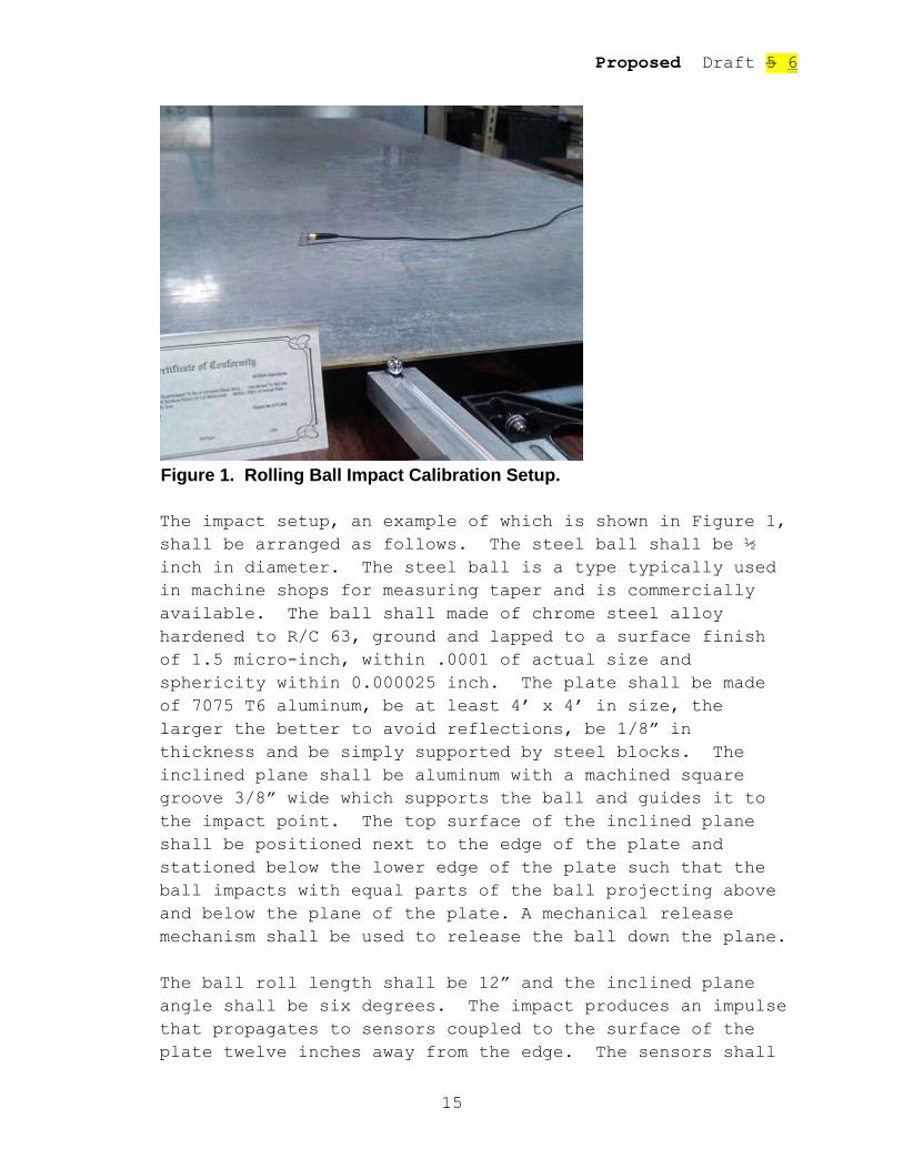
Figure 1. Rolling Ball Impact Calibration Setup.
The impact setup, an example of which is shown in Figure 1, shall be arranged as follows. The steel ball shall be ½ inch in diameter. The steel ball is a type typically used in machine shops for measuring taper and is commercially available. The ball shall made of chrome steel alloy hardened to R/C 63, ground and lapped to a surface finish of 1.5 micro-inch, within .0001 of actual size and sphericity within 0.000025 inch. The plate shall be made of 7075 T6 aluminum, be at least 4’ x 4’ in size, the larger the better to avoid reflections, be 1/8” in thickness and be simply supported by steel blocks. The inclined plane shall be aluminum with a machined square groove 3/8” wide which supports the ball and guides it to the impact point. The top surface of the inclined plane shall be positioned next to the edge of the plate and stationed below the lower edge of the plate such that the ball impacts with equal parts of the ball projecting above and below the plane of the plate. A mechanical release mechanism shall be used to release the ball down the plane.
The ball roll length shall be 12” and the inclined plane angle shall be six degrees. The impact produces an impulse that propagates to sensors coupled to the surface of the plate twelve inches away from the edge. The sensors shall
Proposed Draft 5 6
16
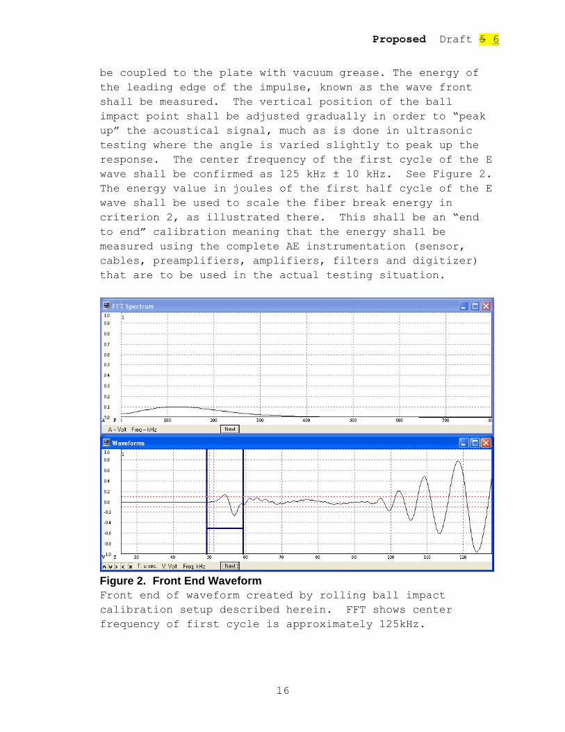
be coupled to the plate with vacuum grease. The energy of the leading edge of the impulse, known as the wave front shall be measured. The vertical position of the ball impact point shall be adjusted gradually in order to “peak up” the acoustical signal, much as is done in ultrasonic testing where the angle is varied slightly to peak up the response. The center frequency of the first cycle of the E wave shall be confirmed as 125 kHz ± 10 kHz. See Figure 2. The energy value in joules of the first half cycle of the E wave shall be used to scale the fiber break energy in criterion 2, as illustrated there. This shall be an “end to end” calibration meaning that the energy shall be measured using the complete AE instrumentation (sensor, cables, preamplifiers, amplifiers, filters and digitizer) that are to be used in the actual testing situation.
Figure 2. Front End Waveform Front end of waveform created by rolling ball impact calibration setup described herein. FFT shows center frequency of first cycle is approximately 125kHz.
Proposed Draft 5 6
17
The energy linearity of the complete AE instrumentation (sensor, cables, preamplifiers, amplifiers, filters and digitizer) shall be measured by using different roll lengths of 8, 12 and 16 inches. The start of the E wave shall be from the first cycle of the waveform recognizable as the front end of the E wave to the end of the E wave which shall be taken as 10 µs later. (The time was calculated from the dispersion curves for the specified aluminum plate.) A linear regression shall be applied to the energy data and a goodness of fit R2 > 0.9 shall be obtained.
4. Preamplifiers and Amplifiers - See ASME Sec. V Article 11.
5. Filters A high pass filter of 20 kHz shall be used. A low pass filter shall be applied to prevent digital aliasing that occurs if frequencies higher than the Nyquist frequency (half the Sampling Rate) are in the signal.
6. A/D The sampling speed and memory depth (wave window length) are dictated by the test requirements and calculated as follows: Vessel length = L inches (meters). Use CE = 0.2 in./μs (5080 m/s) and CF = 0.05 in./μs (1270 m/s), the speeds of the first arriving frequency in the E wave and last arriving frequency in the F wave, respectively, as a guide. The actual dispersion curves for the material shall be used if available. L / CE = T1 μs. This is when the first part of the direct E wave will arrive. L / CF = T2 μs. This is when the last part of the direct F wave will arrive. (T2 – T1) x.1.5 is the minimum waveform window time and allows for pretrigger time. The recording shall be quiescent before front end of the E wave arrives. This is called a “clean front end”. Clean is defined in SX.11(f)(2)(b)below.
Proposed Draft 5 6
18
The sampling rate, or sampling speed, shall be such that aliasing does not occur. The recording system (consisting of all amplifiers, filters and digitizers beyond the sensor) shall be calibrated by using a 20 cycle long tone burst with 0.1 V amplitude at 100, 200, 300, and 400 kHz. The system shall display an energy of U= (V2 · N · T)/2Z joules at each frequency, where V=0.1 volts, N = 20, Z is the preamplifier input impedance and T is the period of the cycle.
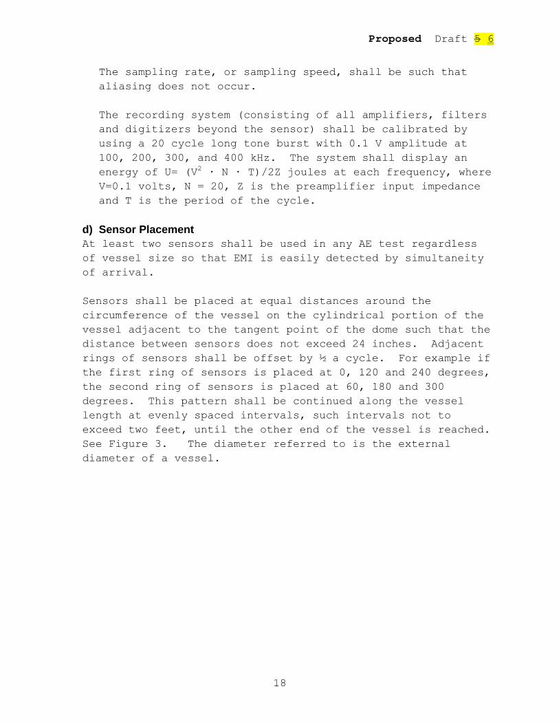
d) Sensor Placement At least two sensors shall be used in any AE test regardless of vessel size so that EMI is easily detected by simultaneity of arrival. Sensors shall be placed at equal distances around the circumference of the vessel on the cylindrical portion of the vessel adjacent to the tangent point of the dome such that the distance between sensors does not exceed 24 inches. Adjacent rings of sensors shall be offset by ½ a cycle. For example if the first ring of sensors is placed at 0, 120 and 240 degrees, the second ring of sensors is placed at 60, 180 and 300 degrees. This pattern shall be continued along the vessel length at evenly spaced intervals, such intervals not to exceed two feet, until the other end of the vessel is reached. See Figure 3. The diameter referred to is the external diameter of a vessel.
Proposed Draft 5 6
19
Figure 3. Sensor spacing and pattern.
Maximum distance between sensors in the axial and circumferential directions shall not exceed two feet. This spacing allows for capturing the higher frequency components of the acoustic emission impulses and high channel count wave recording systems are readily available.
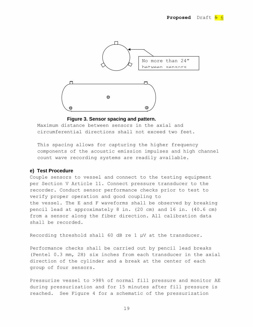
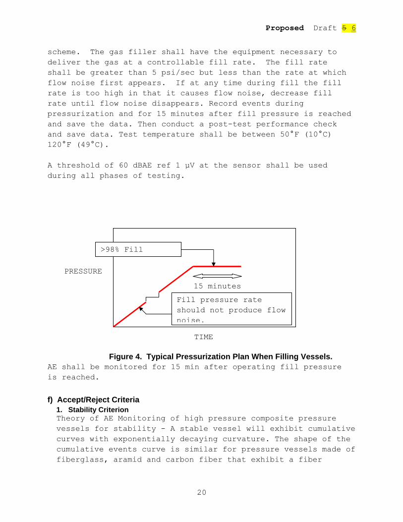
e) Test Procedure Couple sensors to vessel and connect to the testing equipment per Section V Article 11. Connect pressure transducer to the recorder. Conduct sensor performance checks prior to test to verify proper operation and good coupling to the vessel. The E and F waveforms shall be observed by breaking pencil lead at approximately 8 in. (20 cm) and 16 in. (40.6 cm) from a sensor along the fiber direction. All calibration data shall be recorded. Recording threshold shall 60 dB re 1 µV at the transducer. Performance checks shall be carried out by pencil lead breaks (Pentel 0.3 mm, 2H) six inches from each transducer in the axial direction of the cylinder and a break at the center of each group of four sensors. Pressurize vessel to >98% of normal fill pressure and monitor AE during pressurization and for 15 minutes after fill pressure is reached. See Figure 4 for a schematic of the pressurization
No more than 24” between sensors
Proposed Draft 5 6
20
scheme. The gas filler shall have the equipment necessary to deliver the gas at a controllable fill rate. The fill rate shall be greater than 5 psi/sec but less than the rate at which flow noise first appears. If at any time during fill the fill rate is too high in that it causes flow noise, decrease fill rate until flow noise disappears. Record events during pressurization and for 15 minutes after fill pressure is reached and save the data. Then conduct a post-test performance check and save data. Test temperature shall be between 50°F (10°C) 120°F (49°C). A threshold of 60 dBAE ref 1 µV at the sensor shall be used during all phases of testing.
Figure 4. Typical Pressurization Plan When Filling Vessels. AE shall be monitored for 15 min after operating fill pressure is reached. f) Accept/Reject Criteria
1. Stability Criterion Theory of AE Monitoring of high pressure composite pressure vessels for stability - A stable vessel will exhibit cumulative curves with exponentially decaying curvature. The shape of the cumulative events curve is similar for pressure vessels made of fiberglass, aramid and carbon fiber that exhibit a fiber
TIME
PRESSURE
15 minutes
>98% Fill
Fill pressure rate should not produce flow noise.
Proposed Draft 5 6
21
dominated failure mode. This is essentially a test that demonstrates the composite is not progressing to failure at the hold pressure.
2. Analysis Procedure Data will include matrix splits, matrix cracks, fiber breaks, and matrix chirps due to fracture surface fretting, and fiber/matrix debonding. Extraneous noise, identified by waveform characteristics, may also be included in the data.
a. Filter data to eliminate any external noise such as electromagnetic interference (EMI), mechanical rubbing, flow noise, etc. Identify noise events by their shape, spectral characteristics, or other information known about the test such as a temporally associated disturbance due to the pressurization system or test fixturing. EMI is characterized by a lack of any mechanical wave propagation characteristics, particularly a lack of dispersion being apparent. EMI can be further identified by simultaneity of arrival on more than one channel. The two criteria shall be considered together to ensure it’s not simply an event that happened to be centered between the sensors. Mechanical rubbing frequencies are usually very low and can be determined by experiment. There should be no flow noise. If the vessel, or a fitting, leaks, this will compromise the data as AE is very sensitive to leaks. Leak noise is characterized by waves that look uniform across the entire length of the waveform window. If a leak occurs during the load hold, the test must be redone. Flow noise is characterized by waves that fill the waveform window. b. Use only events that have clean front ends and in which first arrival channel can be determined. Clean means having a pre-trigger energy of less than 0.01 x 10⁻¹⁰ joules. Energy is computed by the integral of the voltage squared over time.
c. Plot first arrival cumulative events versus time. Plots shall always show the pressure data.
Proposed Draft 5 6
22
d. Apply exponential fits by channel for pressure hold time and display both data and fit. The values are determined by the fit to y = AeBt +C. The B value is the shape factor of the cumulative curves. C is an intercept and A is a scale factor. The time t shall be equal intervals during the hold with events binned by time interval. Record exponents and goodness of fit (R2). Plot energy decay curves. One third or one fourth of hold time shall be used for event energy binning (cumulative energy). The formula is y=AeBt. The sequence of energy values must monotonically decrease. This is similar to using other energy criteria, such as Historic Index. A sequence that is not properly decreasing will be indicated by a low R2 value. e. Save all plots (all channels) to report document. f. Record exponents and R² values. g. i) Vessel B values shall be tracked and compiled in order to develop a statistically significant database. ii) B is the critical value that measures the frequency of occurrence of events during pressure hold. iii) Not every vessel will have the exact same B value. iv) Data on B values should cluster. The criteria given below apply to each individual sensor on the vessel.
1. The stability criteria as described above shall be met. (Also see ASME Section X Mandatory Appendix 8.) Any vessel that does not meet the stability criteria must be removed from service. The criteria are:
a. Cumulative Event Decay Rate -0.1 < B < -0.0001, R² ≥ 0.80 b. Cumulative Energy Decay Rate -0.2 < B < -0.001, R² ≥ 0.80
Proposed Draft 5 6
23
If these criteria are not met, the vessel does not pass. The vessel may be retested. An AE Level III inspector must review the data from the initial testing and the subsequent loading test before the vessel can be passed. Retest loadings shall follow the original pressurization rates and pressures and use a threshold of 60 dBAE. If the vessel fails the criteria again, the vessel shall not be certified by the Inspector as meeting the provisions of this Section.
2. Events that occur at the higher loads during pressurization having significant energy in the frequency band f > 300 kHz are due to fiber bundle, or partial bundle, breaks. These should not be present at operating pressure in a vessel that has been tested to a much higher pressures and is now operated at the much lower service pressure. For fiber bundles to break in the upper twenty percent of load during the test cycle or while holding at operating pressure, the vessel has a severe stress concentration and shall be removed from service.
g) Fiber Breakage Criterion
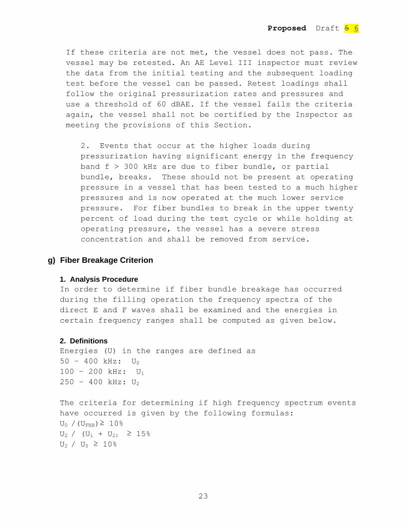
1. Analysis Procedure In order to determine if fiber bundle breakage has occurred during the filling operation the frequency spectra of the direct E and F waves shall be examined and the energies in certain frequency ranges shall be computed as given below. 2. Definitions Energies (U) in the ranges are defined as 50 – 400 kHz: U0 100 – 200 kHz: U1 250 – 400 kHz: U2 The criteria for determining if high frequency spectrum events have occurred is given by the following formulas: U0 /(UFBB)≥ 10% U2 / (U1 + U2) ≥ 15% U2 / U0 ≥ 10%

Proposed Draft 5 6
24
UFBB is the energy of a fiber bundle break calculated using the average breaking strength found in the literature, either from the manufacturer’s data or independent test data. The formula that shall be used for calculating average fiber break energy is
AlU EFB
2
2 ,
where ε is the strain to failure of the fiber, E the Young’s modulus of the fiber, A is area of the fiber and l is the ineffective fiber length for the fiber and matrix combination. If the ineffective length is not readily available, four (4) times the fiber diameter shall be used. We take UFBB = 100 x
UFB, where FBU has been calculated and scaled by the rolling ball impact energy as in the examples below. If these criteria are met, fiber bundle break damage has occurred during the test and the vessel should be removed from service. Common fiber bundle sizes are 1000 and 3000 fibers per tow so 100 fibers represents a partial bundle break.
3. Example of Fiber Break Energy Calculation Suppose d = 7 µm, E = 69.6 GPa and ε = 0.01 (average breaking strain) for some carbon fiber. Using A = πd2/4 and l = 4d,
UFB = 3x10⁻⁸ J. 4. Example of Scaling Calculation Suppose that the rolling ball impact (RBI) acoustical energy measured by a particular high fidelity AE transducer is UAERBI = 5 x 10⁻¹⁰ J and the impact energy URBI = 1.9 x 10⁻³ J (due to gravity). Fiber break energy of T300 carbon fiber UFB = 3x10⁻⁸ J would correspond to a wave energy
UAEFB = UFB x UAERBI / URBI
= 3x10-8 J x 5 x 10-10 J / 1.9 x 10⁻³ J
= 7.9 x 10⁻¹⁵ J.

Proposed Draft 5 6
25
This is the number that is used to calculate the value of UFBB that is used in the fiber break criterion in this the second acceptance criterion and the energy acceptance criterion in the third criterion below.
5. Amplifier Gain Correction All energies shall be corrected for gain. (20 dB gain increases apparent energy 100 times and 40 dB gain 10,000 times.) Fiber break waves may look similar to matrix event waves in time space but in frequency space the difference is clear. A fiber break is a very fast source, while a matrix crack evolves much more slowly due to greater than ten to one difference in their tensile moduli. The speed of the fiber break produces the high frequencies, much higher than a matrix crack event can produce. Frequencies higher than 2 MHz have been observed in proximity to a fiber break, however these very high frequencies are attenuated rapidly as the wave propagates. Practically speaking, the observation of frequencies above 300 kHz, combined with certain other characteristics of the frequency spectrum and pressure level, is enough to confirm a fiber break. It should also be noted that it is fiber bundle breaks that are usually detected in structural testing and not the breaking of individual fibers. The energies of individual fiber breaks are very small, about 3x10⁻⁸ Joules for T-300 carbon fibers for example.
If fiber breakage is determined to have occurred, the vessel shall be removed from service.
h) Friction between Fracture Surfaces Friction between fracture surfaces plays a very important role in understanding AE in fatigue testing. It is an indicator of the presence of damage because it is produced by the frictional rubbing between existing and newly created fracture surfaces. Even the presence of fiber bundle breakage can be detected by examining the waveforms produced by frictional acoustic emission or FRAE. Increasing FRAE intensity throughout a pressure cycle means more and more damage has occurred.

Proposed Draft 5 6
26
Therefore, for a vessel to pass, no AE event shall have an energy greater than (F) x UFB at anytime during the test. F is the acoustic emission allowance factor. The smaller the allowance factor, the more conservative the test. An F = 104 shall be used in this testing. It is the equivalent of three plus fiber tows, each tow consisting of 3,000 fibers, breaking simultaneously near a given transducer. i) Background Energy Background energy of any channel shall not exceed 10 times the quiescent background energy of that channel. After fill pressure is reached, any oscillation in background energy with a factor of two excursions between minima and maxima shows that the vessel is struggling to handle the pressure. Pressure shall be reduced immediately and the vessel removed from service.