bf135a-ec en n - jetski diagnostics , seadoo buds mil comes on baro sensor (voltage too low) †...
TRANSCRIPT

BF135A•BF150A

CONTENTS
SPECIFICATIONS 1SERVICE INFORMATION 2MAINTENANCE 3ENGINE COVER/COVER LOCK 4PROGRAMMED-FUEL INJECTION 5ALTERNATOR 6ENGINE REMOVAL/INSTALLATION 7THERMOSTAT/RELIEF VALVE/FLUSH VALVE 8CRANKSHAFT PULLEY/CAM CHAIN 9CYLINDER HEAD/VALVES 10OIL PUMP/FLYWHEEL 11CRANKCASE/BALANCER 12CYLINDER BLOCK/CRANKSHAFT/PISTONS 13PROPELLER/GEAR CASE/EXTENSION CASE/OIL CASE 14MOUNTING CASE/STERN BRACKET/SWIVELCASE/POWER TRIM/TILT ASSEMBLY 15STEERING ROD/REMOTE CONTROL BOX 16CABLES/SHIFT LINK BRACKET/SHIFT ARM/NEUTRAL SWITCH 17ELECTRICAL EQUIPMENT 18OPERATION 19WIRING DIAGRAM/SYSTEM DIAGRAM 20
2121
Date of lssue: Feb.2008© Honda Motor Co., Ltd.
PREFACEThis supplement covers the use of the Dr. H to trou-bleshoot the BF135A • BF150A Outboard Motors.
For service information which is not covered in this sup-plement, please refer to the base shop manual (partnumber 66ZY600).
No part of this publication may be reproduced, stored ina retrieval system, or transmitted, in any form, by anymeans, electronic, mechanical, photocopying, record-ing, or otherwise, without prior written permission of thepublisher. This includes text, figures, and tables.
As you read this manual, you will find information that ispreceded by a symbol.The purpose of this mes-sage is to help prevent damage to the outboard motor,other property, or the environment.
SAFETY MESSAGESYour safety, and the safety of others, are very important.To help you make informed decisions, we have provid-ed safety messages and other safety informationthroughout this manual. Of course, it is not practical orpossible to warn you about all the hazards associatedwith servicing these outboard motors. You must useyour own good judgment.
You will find important safety information in a variety offorms, including:
• Safety Messages -- preceded by a safety alert symbol and one of three signal words, DANGER,WARNING, or CAUTION.
These signal words mean:
You WILL be KILLED orSERIOUSLY HURT if youdon't follow instructions.
You CAN be KILLED orSERIOUSLY HURT if youdon't follow instructions.
You CAN be HURT if youdon't follow instructions.
• Instructions -- how to service this outboard motorcorrectly and safely.
Honda Motor Co., LtdService Publication Office
NOTICE
DANGER
WARNING
CAUTION
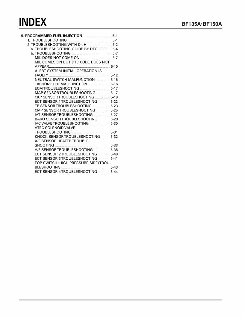
5. PROGRAMMED-FUEL INJECTION ............................ 5-1
1. TROUBLESHOOTING ............................................ 5-12.TROUBLESHOOTING WITH Dr. H ........................ 5-2
a. TROUBLESHOOTING GUIDE BY DTC.............. 5-4b. TROUBLESHOOTING ........................................ 5-7
MIL DOES NOT COME ON................................ 5-7MIL COMES ON BUT DTC CODE DOES NOTAPPEAR............................................................. 5-10ALERT SYSTEM INITIAL OPERATION IS FAULTY ............................................................. 5-12NEUTRAL SWITCH MALFUNCTION .............. 5-15TACHOMETER MALFUNCTION ...................... 5-16ECM TROUBLESHOOTING .............................. 5-17MAP SENSOR TROUBLESHOOTING.............. 5-17CKP SENSOR TROUBLESHOOTING ............... 5-19ECT SENSOR 1 TROUBLESHOOTING ............ 5-22TP SENSOR TROUBLESHOOTING.................. 5-23CMP SENSOR TROUBLESHOOTING.............. 5-25IAT SENSOR TROUBLESHOOTING ................ 5-27BARO SENSOR TROUBLESHOOTING............ 5-28IAC VALVE TROUBLESHOOTING .................... 5-30VTEC SOLENOID VALVE TROUBLESHOOTING ...................................... 5-31KNOCK SENSOR TROUBLESHOOTING ......... 5-32A/F SENSOR HEATER TROUBLE-SHOOTING ....................................................... 5-33A/F SENSOR TROUBLESHOOTING ................ 5-38ECT SENSOR 2 TROUBLESHOOTING ............ 5-40ECT SENSOR 3 TROUBLESHOOTING ............ 5-41EOP SWITCH (HIGH PRESSURE SIDE) TROU-BLESHOOTING................................................. 5-43ECT SENSOR 4 TROUBLESHOOTING ............ 5-44
INDEX

5-1
1. TROUBLESHOOTINGThe ECM (Engine Control Module) has the self-diagno-sis function which memorizes the failure code and turnsthe MIL (Malfunction Indicator Light) ON when it detectsan abnormality with the input/output system.
• HOW TO CARRY OUT TROUBLESHOOTING
When the MIL comes ON or blinks or any abnormalityoccurs during running, identify the problem detected byECM according to the following procedure, and trou-bleshoot accordingly.
To troubleshoot, connect the tester probe to a commer-cially available digital circuit tester. Note that the testerprobe must agree with the connector terminal of the dig-ital circuit tester not to apply excessive force to the con-nector terminal.
1. Turn the ignition switch ON and check that the MILcomes ON.
2. When the MIL is ON or blinking, check the DTC(Diagnostic Trouble Code) using the Dr. H (P. 5-2).
3. Perform the troubleshooting by referring to the “Trou-bleshooting Guide by DTC” (P. 5-4).
Check each connector and wire harness for secureconnection and damage before troubleshooting.Repair the connector and wire harness if necessary.
4. After troubleshooting, perform repairs as neededand perform the necessary work (P. 5-3).
PGM-FI MIL
1.TROUBLESHOOTING 2. TROUBLESHOOTING WITH Dr. H
5. PROGRAMMED FUEL INJECTION

5-2
2. TROUBLESHOOTING WITH Dr. H
• DTC (DIAGNOSTIC TROUBLECODE) CHECK
1. Remove the engine cover and the electric part cover(Section 4 of the base manual).
2. Disconnect the 4P (Red) connector and connect theDr. H to the data link connector (DLC).
3. Turn the ignition switch ON and check the DTCshown on the Dr. H.
Refer to the Dr. H's operation manual for how to usethe Dr. H.
• WHEN USING Dr. H DURINGCRUISING
1. Remove the engine cover and the electric part cover(Section 4 of the base manual).
2. Remove the cap from the under cover front bracket.Route the extension wire through the front coverbracket.
• Set the grommet on the under cover front bracketsecurely.
3. Disconnect the red 4P connector from the DLC(Data Link Connector) and secure the DLC wire assown.
• Route the extension wire of the tester in the posi-tion shown so that it does not interfere with theparts.
4. Connect the extension wire to the DLC.
4P CONNECTOR(RED)
TESTER WIRE DATA LINK CONNECTOR (DLC)
CAP
EXTENSION WIREOF TESTER
CLAMP DLC
UNDER COVERFRONT BRACKET
TESTER WIRE

5-3
5. Secure the extension wire as shown with the band.
6. Connect the extension wire to the Dr. H.
7. Install the electric part cover and the engine cover inthe reverse order of removal.
• TO CLEAR DTC1. Remove the engine cover and the electric part cover.
2. Connect the Dr. H to the data link connector (DLC).
3. Turn the ignition switch ON.
4. Clear the DTC using the Dr. H.
Refer to the Dr. H's operation manual for how to usethe Dr. H.
• When abnormality remains in the system, the DTCcannot be cleared as the ECM continues self-diag-nosis.
• FINAL PROCEDURE (AFTER TROUBLESHOOTING)
1. Clear the DTC.
2. Disconnect the Dr. H wire from the data link connector.
3. Install the cap on the under cover front bracket.
4. Install the electric part cover and the engine cover.
EXTENSION WIREOF TESTER
WIRE BAND
5-4
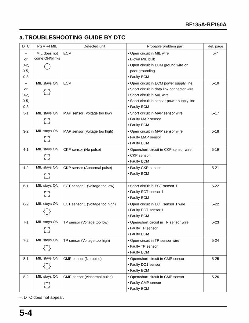
a. TROUBLESHOOTING GUIDE BY DTC
–: DTC does not appear.
DTC PGM-FI MIL Detected unit Probable problem part Ref. page
– MIL does not ECM • Open circuit in MIL wire 5-7
or come ON/blinks • Blown MIL bulb
0-2, • Open circuit in ECM ground wire or
0-5, poor grounding
0-8 • Faulty ECM
– MIL stays ON ECM • Open circuit in ECM power supply line 5-10
or • Short circuit in data link connector wire
0-2, • Short circuit in MIL wire
0-5, • Short circuit in sensor power supply line
0-8 • Faulty ECM
3-1 MIL stays ON MAP sensor (Voltage too low) • Short circuit in MAP sensor wire 5-17
• Faulty MAP sensor
• Faulty ECM
3-2 MIL stays ON MAP sensor (Voltage too high) • Open circuit in MAP sensor wire 5-18
• Faulty MAP sensor
• Faulty ECM
4-1 MIL stays ON CKP sensor (No pulse) • Open/short circuit in CKP sensor wire 5-19
• CKP sensor
• Faulty ECM
4-2 MIL stays ON CKP sensor (Abnormal pulse) • Faulty CKP sensor 5-21
• Faulty ECM
6-1 MIL stays ON ECT sensor 1 (Voltage too low) • Short circuit in ECT sensor 1 5-22
• Faulty ECT sensor 1
• Faulty ECM
6-2 MIL stays ON ECT sensor 1 (Voltage too high) • Open circuit in ECT sensor 1 wire 5-22
• Faulty ECT sensor 1
• Faulty ECM
7-1 MIL stays ON TP sensor (Voltage too low) • Open/short circuit in TP sensor wire 5-23
• Faulty TP sensor
• Faulty ECM
7-2 MIL stays ON TP sensor (Voltage too high) • Open circuit in TP sensor wire 5-24
• Faulty TP sensor
• Faulty ECM
8-1 MIL stays ON CMP sensor (No pulse) • Open/short circuit in CMP sensor 5-25
• Faulty DC1 sensor
• Faulty ECM
8-2 MIL stays ON CMP sensor (Abnormal pulse) • Open/short circuit in CMP sensor 5-26
• Faulty CMP sensor
• Faulty ECM

5-5
DTC PGM-FI MIL Detected unit Probable problem part Ref. page
10-1 MIL comes ON IAT sensor (Voltage too low) • Short circuit in IAT sensor wire 5-27
• Faulty IAT sensor
• Faulty ECM
10-2 MIL comes ON IAT sensor (Voltage too high) • Open circuit in IAT sensor wire 5-27
• Faulty IAT sensor
• Faulty ECM
13-1 MIL comes ON BARO sensor (Voltage too low) • Short circuit in BARO sensor wire 5-28
• Faulty BARO sensor
• Faulty ECM
13-2 MIL comes ON BARO sensor (Voltage too high) • Open circuit in BARO sensor wire 5-29
• Faulty BARO sensor
• Faulty ECM
14-1 MIL comes ON IAC valve (Abnormal current flow) • Open/short circuit in IAC valve wire 5-30
• Faulty IAC valve
• Faulty ECM
21-1 MIL comes ON VTEC solenoid valve • Open/short circuit in VTEC solenoid valve 5-31
(Abnormal output)(BF150A only) • Faulty VTEC solenoid valve
• Faulty ECM
23-1 MIL comes ON Knock sensor (Abnormal detection) • Open/short circuit in knock sensor wire 5-32
• Faulty knock sensor
• Faulty ECM
41-3 MIL comes ON A/F sensor heater • Open/short circuit in A/F sensor heater wire 5-33
(Abnormal current flow) • Faulty A/F sensor heater
• Faulty ECM
41-4 MIL comes ON A/F sensor heater • Open/short circuit in A/F sensor heater wire 5-35
(Abnormal current flow) • Faulty A/F sensor heater
• Faulty ECM
48-5 MIL comes ON A/F sensor heater • Open circuit in A/F sensor heater wire 5-38
(Abnormal current flow) • Faulty A/F sensor
• Faulty ECM
48-6 MIL comes ON A/F sensor heater • Short circuit in A/F sensor wire C line 5-39
(Abnormal current flow) • Faulty A/F sensor
• Faulty ECM
48-7 MIL comes ON A/F sensor heater • Short circuit in A/F sensor wire V line 5-39
(Abnormal current flow) • Faulty A/F sensor
• Faulty ECM

5-6
When multiple DTC’s main codes are indicated:
DTC PGM-FI MIL Detected unit Probable problem part Ref. page
140-1 MIL comes ON ECT sensor 2 (Voltage too low) • Short circuit in ECT sensor 2 wire 5-40
• Faulty ECT sensor 2
• Faulty ECM
140-2 MIL comes ON ECT sensor 2 (Voltage too high) • Open circuit in ECT sensor 2 wire 5-40
• Faulty ECT sensor 2
• Faulty ECM
141-1 MIL comes ON ECT sensor 3 (Voltage too low) • Short circuit in ECT sensor 3 wire 5-41
• Faulty ECT sensor 3
• Faulty ECM
141-2 MIL comes ON ECT sensor 3 (Voltage too high) • Open circuit in ECT sensor 3 wire 5-42
• Faulty ECT sensor 3
• Faulty ECM
142-1 MIL comes ON EOP switch • Open/short circuit in EOP switch wire 5-43
(Abnormal signal) • Faulty ECM
143-1 MIL comes ON ECT sensor 4 (Voltage too low) • Short circuit in ECT sensor 4 wire 5-44
• Faulty ECT sensor 3
• Faulty ECM
143-2 MIL comes ON ECT sensor 4 (Voltage too high) • Open circuit in ECT sensor 4 wire 5-45
• Faulty ECT sensor 4
• Faulty ECM
DTCPGM-FI MIL Detected unit Probable problem part Ref. pagemain
codes
7, 13 MIL comes ON • Open circuit in VCC line
(power source for sensor)
6,7 MIL comes ON • Open circuit in SG (sensor ground) line
10,13
48,140
141,143

5-7
b. TROUBLESHOOTING
• MIL Does Not Come ON1. Fuse check-1. Turn the ignition switch ON and check that the warn-
ing buzzer sounds twice.
Does the buzzer sound twice?YES – Perform “6. Alternator indicator light check”NO – Go to the step 2.
-2. Check the No. 4 (15A) fuse.
Is the fuse normal?YES – Go to the step 3.NO – Repair open in the wire between the No. 4
fuse and the ECM, and between the No. 4fuse and the injector. After repair, replacethe No. 4 fuse.
-3. Check the No. 7 (30A) fuse.
Is the fuse normal?YES – Go to the step 4.NO – Repair short in the wire between the PGM-
FI main relay and the fuse box, andbetween the PGM-FI main relay and thestarter magnetic switch. After repair,replace the No. 7 fuse.
-4. Check the No. 3 (30A) fuse.
Is the fuse normal?YES – Perform “2. Main power line check”.NO – Repair short in the wire between the fuse
box and the ignition switch, between thefuse box and the alternator, and betweenthe fuse box and the power trim/tilt switchor power tilt switch. After repair, replacethe No. 3 fuse.
2. Main power line check-1. Disconnect the remote control harness 14P connector.-2. Measure the voltage between the No. 3 (White/Black)
terminal of the main harness side 14P connectorand the engine ground.• Note that voltage is constantly applied to the
White/Black terminal. Take care not to short-circuitthe terminal.
Is there the battery voltage?YES – Go to the step 3.NO – Repair open in the main harness.
-3. Turn the ignition switch ON. Check for continuitybetween the No. 1 (White/Black) terminal and theNo. 2 (Black/Yellow) terminal of the remote controlbox harness side 14P connector.
Is there the continuity?YES – Perform “3. IGP power line check”.NO – Go to the step 4.
-4. Check the ignition switch (P. 16-9 of the base manual).
Is the ignition switch normal?YES – Repair open in the remote control box har-
ness.NO – The ignition switch is faulty.
MAIN HARNESS SIDE14P CONNECTOR BLACK/WHITE
VIEWED FROM THETERMINAL SIDE
VIEWED FROM THETERMINAL SIDE
REMOTE CONTROLHARNESS SIDE 14PCONNECTOR
WHITE/BLACK
BLACK/YELLOW

5-8
3. IGP power line check-1. Turn the ignition switch OFF. Disconnect the PGM-FI
main relay 6P connector.-2. Turn the ignition switch ON. Measure the voltage
between the No. 2 (Black/Yellow) terminal of thePGM-FI main relay harness side 6P connector andthe engine ground.
Is there the battery voltage?YES – Go to the step 3.NO – Repair open in the main harness.
-3. Turn the ignition switch OFF. Check for continuitybetween the No. 6 (Black) terminal of the PGM-FImain relay 6P connector and the engine ground.
Is there the continuity?YES – Perform “4. ECM power line check”.NO – Repair open in the main harness (Black).
4. ECM power line check-1. Turn the ignition switch OFF and disconnect the fuse
box 3P connector.-2. Turn the ignition switch ON. Measure the voltage
between the No. 3 (Yellow/Black) terminal of the fusebox side 3P connector and the engine ground.
Is there the battery voltage?YES – Go to the step 3.NO – The PGM-FI main relay is faulty, or the fuse
box is faulty.
-3. Turn the ignition switch OFF and disconnect theECM connector C.
-4. Check for the continuity between the No. 2 (Yellow/Black) terminal of the fuse box harness side 3P con-nector and the respective terminals of the No. 1(Yellow/Black) and No. 5 (Yellow/Black) terminals ofthe ECM connector C.
Is there the continuity?YES – Perform “5. MIL power line check”.NO – Repair open in the wire of the main har-
ness.
PGM-FI MAIN RELAY HARNESSSIDE 6P CONNECTOR
VIEWED FROM THETERMINAL SIDE
VIEWED FROM THETERMINAL SIDE
FUSE BOX SIDE 3P CONNECTOR
VIEWED FROM THETERMINAL SIDE
ECM CONNECTOR C
VIEWED FROM THETERMINAL SIDE
FUSE BOX HARNESSSIDE 3P CONNECTOR
BLACK
YELLOW/BLACK
IGP2(YELLOW/BLACK)
IGP1(YELLOW/BLACK)
BLACK/YELLOWYELLOW/BLACK
PGM-FI MAIN RELAY HARNESSSIDE 6P CONNECTOR

5-9
6. Alternator indicator light check-1. Turn the ignition switch ON and check the alternator
indicator light.
Does the alternator indicator light come ON?YES – Perform “8. Function test”.NO – Replace the MIL.
7. MIL line check-1. Turn the ignition switch OFF and disconnect the
ECM connector B.-2. Disconnect the MIL 6P connector.-3. Check for continuity between the No. 25 (Red/Blue)
terminal of the ECM harness side connector B andthe No. 4 (Red/Blue) terminal of the MIL harnessside 6P connector.
Is there the continuity?YES – Go to the step 4.NO – Repair open in the main harness.
-4. Check for continuity between the No. 4 (Yellow/Black) terminal and the No. 6 (Red/Blue) terminal ofthe MIL 6P connector.
Is there the continuity?YES – Substitute a known-good ECM and
recheck.NO – MIL is faulty or open circuit in the MIL har-
ness wire.
5. MIL power line check-1. Turn the ignition switch OFF and disconnect the fuse
box 3P connector.-2. Turn the ignition switch ON. Measure the voltage
between the No. 2 (Yellow/Red) terminal of the fusebox side 3P connector and the engine ground
Is there the battery voltage?YES – Go to the step 3.NO – The PGM-FI main relay is faulty.
-3. Turn the ignition switch OFF and connect the fusebox 3P connector.
-4. Disconnect the MIL 6P connector.-5. Turn the ignition switch ON. Measure the voltage
between the No. 6 (Yellow/Black) terminal of the MIL6P harness side connector and the engine ground.
Is there the battery voltage?YES – Perform “6. Alternator indicator light
check”.NO – Repair open in the main wire harness.
FUSE BOX SIDE 3P CONNECTOR
YELLOW/RED
VIEWED FROM THETERMINAL SIDE
MIL HARNESS SIDE6P CONNECTOR
VIEWED FROM THETERMINAL SIDE
MIL HARNESS SIDE6P CONNECTOR
WARNL(RED/BLUE)
ECM CONNECTOR B
VIEWED FROM THETERMINAL SIDE
YELLOW/BLACK
MIL 6P CONNECTOR
VIEWED FROM THETERMINAL SIDE
YELLOW/BLACK RED/BLUE

5-10
8. Function test-1. Turn the ignition switch OFF and connect the Dr. H.-2. Turn the ignition switch ON and perform the function
test. (See the Dr. H's operation manual for the testprocedure.)
Does the MIL blink?YES – Substitute a known-good ECM and recheck.NO – Check the MIL.
If the MIL is normal, repair the main wireharness (open in the Red/Blue wirebetween the MIL and ECM).
• MIL Comes ON but DTC CodeDoes Not Appear
1. ECM power line check-1. Turn the ignition switch OFF and disconnect the
ECM connector C.-2. Turn the ignition switch ON. Measure the voltage
between the respective terminals of the No. 2(Yellow/Black) and No. 6 (Yellow/Black) terminals ofthe ECM connector C and the engine ground.
Is there the battery voltage?YES – Perform “2. Data link connector check”.NO – Repair open in the main harness.
2. Data link connector check-1. Turn the ignition switch OFF and disconnect the Dr. H.-2. Turn the ignition switch ON. Measure the voltage
between the No. 4 (Yellow/Red) terminal of the datalink connector and the engine ground.
Is there the battery voltage?YES – Go to the step 3.NO – Repair open in the main harness.
VIEWED FROM THETERMINAL SIDE
DATA LINK CONNECTOR
VIEWED FROM THETERMINAL SIDE
ECM CONNECTOR C
IGP2(YELLOW/BLACK)
IGP1(YELLOW/BLACK)
YELLOW/RED

5-11
-3. Turn the ignition switch OFF and disconnect theECM connector B.
-4. Check for the continuity between the No. 3 (Lightgreen/White) terminal of the data link connector andthe engine ground.
Is there the continuity?YES – Repair short in the main harness.NO – Go to the step 5.
-5. Check for the continuity between the No. 3 (Lightgreen/White) terminal of the data link connector andthe No. 16 (Light green/White) terminal of the ECMharness side connector B.
Is there the continuity?YES – Go to the step 6.NO – Repair open in the main harness.
-6. Check for the continuity between the service checkconnector No. 1 (Black) terminal and the engineground.
Is there the continuity?YES – Perform “3. DTC recheck”.NO – Repair open in the main harness.
3. DTC recheck-1. Turn the ignition switch OFF and connect the Dr. H.-2. Turn the ignition switch ON and check the DTC with
the Dr. H.
Is the main code 0 (either of 0-2, 0-5 or 0-8)?YES – Substitute a known-good ECM and
recheck.NO – Troubleshoot the problem of the DTC.
DATA LINK CONNECTOR
VIEWED FROM THETERMINAL SIDE
ECM CONNECTOR BDATA LINKCONNECTOR
DATA LINKCONNECTOR
VIEWED FROM THETERMINAL SIDE
VIEWED FROM THETERMINAL SIDE
LIGHT GREEN/WHITE
SCS(LIGHT GREEN/WHITE)
GND(BLACK)

5-12
• Alert System Initial Operation IsFaulty
1. Function test-1. Turn the ignition switch OFF and connect the Dr. H.-2. Turn the ignition switch ON and test the buzzer using
the Dr. H.
Does the buzzer sound?YES – Go to the step 3.NO – Perform “2. Buzzer line check”.
-3. Test the MIL using the Dr. H.
Does the MIL blink?YES – Go to the step 4.NO – Perform “3. MIL line check”.
-4. Test the overheat indicator light using the Dr. H.
Does the overheat indicator light blink?YES – Go to the step 5.NO – Perform “4. Overheat indicator line check”.
-5. Test the oil pressure indicator light using the Dr. H.
Does the oil pressure indicator light blink?YES – End of the testNO – Perform “5. Oil pressure indicator line
check”.
2. Buzzer line check-1. Turn the ignition switch OFF and disconnect the
Yellow/Green terminal from the buzzer.-2. Connect the Yellow/Green terminal of the buzzer to
the Black terminal with a jumper wire to short.-3. Turn the ignition switch ON and check that the
buzzer sounds.
Does the buzzer sound?YES – Repair open in the wire harness (wire
between the buzzer and ECM).NO – Go to the step 4.
-4. Perform the unit check of the buzzer.
Is the buzzer normal?YES – Go to the step 5.NO – The buzzer is faulty.
-5. Perform the unit check of the ignition switch (P. 16-9of the base manual).
Is the ignition switch normal?YES – Go to the step 6.NO – The ignition switch is faulty.
-6. Disconnect the remote control box harness side 14Pconnector.
-7. Turn the ignition switch ON. Check for the continuitybetween the No. 1 (White/Black) and the No. 2(Black/Yellow) terminals of the remote control boxharness side 14P connector.
Is there continuity?YES – Repair open in the main harness.NO – Repair open in the remote control box har-
ness.
REMOTE CONTROL BOXHARNESS SIDE 14PCONNECTOR
VIEWED FROM THETERMINAL SIDE
WHITE/BLACKBLACK/YELLOW

5-13
-5. Check for continuity between the No. 4 (Yellow/Black) terminal and the No. 6 (Red/Blue) terminal ofthe MIL 6P connector.
Is there the continuity?YES – Substitute a known-good ECM and recheck.NO – The MIL is faulty or repair open in the MIL
harness.
3. MIL line check-1. Turn the ignition switch OFF and disconnect the MIL
6P connector.-2. Turn the ignition switch ON. Measure the voltage
between the No. 2 (Yellow/Red) terminal of the MIL6P main harness side connector and the engineground.
Is there the battery voltage?YES – Go to the step 3.NO – Repair open in the main wire harness.
-3. Turn the ignition switch OFF and disconnect theECM connector B.
-4. Check for the continuity between the No. 25(Red/Blue) terminal of the ECM harness side con-nector B and the No. 4 (Red/Blue) terminal of theMIL main harness side 6P connector.
Is there the continuity?YES – Go to the step 5.NO – Repair open in the main harness.
MIL HARNESS SIDE 6PCONNECTOR
VIEWED FROM THETERMINAL SIDE
MIL HARNESS SIDE6P CONNECTOR
ECM CONNECTOR B
VIEWED FROM THETERMINAL SIDE
MIL 6P CONNECTOR
VIEWED FROM THETERMINAL SIDE
YELLOW/BLACK RED/BLUE
YELLOW/RED
WHITE/BLACK

5-14
4. Overheat indicator line check-1. Turn the ignition switch OFF. Disconnect the Red
terminal of the indicator light and connect the Blackterminal to short.
-2. Turn the ignition switch ON and check the overheatindicator light.
Does the overheat indicator light come ON?YES – Repair open in the wire harness (between
the ECM and the indicator light).NO – Go to the step 3.
-3. Turn the ignition switch OFF and connect the indicatorlight Red terminal.
-4. Disconnect the remote control harness 14P connector.-5. Check for the continuity between the No. 7 (Red) ter-
minal and the No. 2 (Black/Yellow) terminal of theremote control harness side 14P connector.
Is there the continuity?YES – Repair open in the wire of the main har-
ness.NO – The indicator light is faulty or repair open in
the remote control harness.
5. Oil pressure indicator line check-1. Turn the ignition switch OFF. Disconnect the Yellow
terminal of the indicator light and connect the Blackterminal to short.
-2. Turn the ignition switch ON and check the oil pres-sure indicator light.
Does the oil pressure indicator light come ON?YES – Go to the step 3.NO – Repair open in the wire harness (between
the ECM and the indicator light).
-3. Turn the ignition switch OFF and connect the indica-tor light Yellow terminal.
-4. Disconnect the remote control harness 14P connector.-5. Check for the continuity between the No. 6 (Yellow)
and the No. 2 (Black/Yellow) terminals of the remotecontrol harness side 14P connector.
Is there the continuity?YES – Repair open in the main harness.NO – The indicator light is faulty or repair open in
the remote control harness wire.
VIEWED FROM THETERMINAL SIDE
REMOTE CONTROLHARNESS SIDE 14PCONNECTOR
VIEWED FROM THETERMINAL SIDE
REMOTE CONTROLHARNESS SIDE 14PCONNECTOR
BLACK/YELLOW
RED
BLACK/YELLOW
YELLOW

5-15
• Neutral Switch Malfunction• Before following test, perform the neutral position check.
Engine speed does not increase in gears (BF150A only).1. Switch condition check with the Dr. H-1. Turn the ignition switch OFF and connect the Dr. H.-2. Turn the ignition switch ON and check the neutral
switch condition using the Dr. H.
Does the switch position agree with the indicationof the tester?YES – Substitute a known-good ECM and recheck.NO – Perform “2. Neutral switch line check”.
2. Neutral switch line check-1. Turn the neutral switch OFF and disconnect the neutral
switch 2P connector.-2. Check for the continuity between the No. 1
(Black/Blue) terminal of the neutral switch harnessside 2P connector and the engine ground.
Is there the continuity?YES – Repair short in the wire of the main harness.NO – Go to the step 3.
-3. Check for the continuity between the No. 2 (Black)terminal of the neutral switch harness side 2P con-nector and the engine ground.
Is there the continuity?YES – Go to the step 4.NO – Repair open in the main wire harness.
-4. Disconnect the ECM connector B.-5. Check for the continuity between the No. 13
(Black/Blue) terminal of the ECM harness side con-nector B and the No. 1 (Black/Blue) terminal of theneutral switch harness side 2P connector.
Is there the continuity?YES – Perform “3. Neutral switch check”.NO – Repair open in the main harness.
3. Neutral switch check
-1. Turn the ignition switch OFF and disconnect the neu-tral switch 2P connector.
-2. Check for the continuity between the No. 1 (Black)terminal and the No. 2 (Black/Blue) terminal of theneutral switch side 2P connector.
Is there the continuity with the gear in Neutral andno continuity with the gear in other than Neutral?YES – Substitute a known-good ECM and recheck.NO – The neutral switch is faulty.
VIEWED FROM THETERMINAL SIDE
BLACK/BLUE
NEUTRAL SWITCH HARNESSSIDE 2P CONNECTOR
VIEWED FROM THETERMINAL SIDE
NEUTRAL SWITCH HARNESSSIDE 2P CONNECTOR
NEUTRAL SWITCHHARNESS SIDE 2PCONNECTOR
ECM CONNECTOR B
VIEWED FROM THETERMINAL SIDE
VIEWED FROM THETERMINAL SIDE
NEUTRAL SWITCH SIDE 2PCONNECTOR
BLACK
NTSW(BLACK/BLUE)

5-16
• Tachometer Malfunction1. Engine speed check using the Dr. H.-1. Turn the ignition switch OFF and connect the Dr. H.-2. Start the engine and check the engine speed with
the Dr. H.
Do the tachometer and tester readings agree?YES – Normal (Temporary problem has been
removed.)NO – Perform “2. Tachometer power line check”.
*Tolerance of genuine Honda tachometer:At 2,000 rpm: ±160 rpmAt 4,000 rpm: +200 rpm
–150 rpmAt 6,000 rpm: +200 rpm
–150 rpm
2. Tachometer power line check-1. Turn the ignition switch OFF and disconnect the
Yellow/Black and the Black terminals of the tachometer.-2. Turn the ignition switch ON and measure the voltage
between the meter harness side Yellow/Black andthe Black terminals.
Is there the battery voltage?YES – Perform “3. Tachometer pulse line check”.NO – Repair open in the wire of the meter harness.
3. Tachometer pulse line check-1. Turn the ignition switch OFF and disconnect the
ECM connector B.-2. Disconnect the remote control harness 14P connector.-3. Check for the continuity between the No. 12 (Gray)
terminal of the main harness side 14P connectorand the engine ground.
Is there the continuity?YES – Repair short in the main harness.NO – Go to the step 4.
-4. Check for the continuity between the No. 12 (Gray)terminal of the main harness side 14P connectorand the No. 33 (Gray) terminal of the ECM harnessside connector B.
Is there the continuity?YES – Check for open in the remote control har-
ness and meter harness wires. If the har-nesses are normal, substitute a known-good ECM and recheck.
NO – Repair open in the wire of the main harness.
MAIN HARNESS SIDE14P CONNECTOR
VIEWED FROM THETERMINAL SIDE
MAIN HARNESS SIDE14P CONNECTOR
ECM CONNECTOR B
VIEWED FROM THETERMINAL SIDE
TACHO(GRAY)
GRAY

5-17
• ECM TroubleshootingDTC 0-2, 0-5, 0-8: Inside of ECM is faulty1. Symptom reproduction test-1. Connect the Dr. H.-2. Turn the ignition switch ON and wait for 1 second or
more.-3. Clear the DTC once.-4. Start the engine and check the DTC again.
Does the DTC 0-2, 0-5, and/or 0-8 appear?YES – Substitute a known-good ECM and recheck.NO – Temporary failure inside ECM (Disappeared)
• MAP Sensor TroubleshootingDTC 3-1: MAP sensor voltage is low1. Symptom reproduction test-1. Connect the Dr. H and clear the DTC once. If the
DTC can not be cleared, go on the troubleshooting.-2. Turn the ignition switch ON.-3. Check the MAP sensor voltage using the Dr. H.
Is the measured voltage 0.22 to 3.15V?YES – Temporary failure (Disappeared)NO – Perform “2. MAP sensor signal line short-
circuit test”.
2. MAP sensor signal line short-circuit test-1. Turn the ignition switch OFF and disconnect the
MAP sensor 3P connector.-2. Disconnect the ECM connector A.-3. Check for the continuity between the No. 2
(White/Red) terminal of the MAP sensor harnessside 3P connector and the body ground.
Is there the continuity?YES – Repair short in the wire between the MAP
sensor and ECM.NO – Perform “3. MAP sensor check”.
3. MAP sensor check-1. Connect the ECM connector A and the MAP sensor
3P connector.-2. Turn the ignition switch ON and read the MAP sen-
sor voltage using the Dr. H.
Is the voltage 2.76 – 2.96V?YES – Substitute a known-good ECM and recheck.NO – Replace the MAP sensor.
MAP SENSOR HARNESSSIDE 3P CONNECTOR
PB (WHITE/RED)
VIEWED FROM THETERMINAL SIDE

5-18
DTC 3-2: MAP sensor voltage is high1. Symptom reproduction test-1. Connect the Dr. H and clear the DTC once. If the
DTC can not be cleared, go on the troubleshooting.-2. Turn the ignition switch ON.-3. Check PB voltage using the Dr. H.
Is the measured voltage 0.22 – 3.15V?YES – Temporary failure (Disappeared)NO – Perform “2. MAP sensor power line check”.
2. MAP sensor power line check-1. Turn the ignition switch OFF and disconnect the
MAP sensor 3P connector.-2. Turn the ignition switch ON.-3. Measure the voltage between the No. 3 (Brown/Yellow)
terminal and the No. 1 (Green/Red) terminal of theMAP sensor harness side 3P connector.
Is the measured voltage 4.75 – 5.25V?YES – Perform “5. MAP sensor signal line open
circuit check”.NO – Perform “3. MAP sensor power line open
circuit check”.
3. MAP sensor power line open circuit check-1. Turn the ignition switch OFF and disconnect the
ECM connector B.-2. Check for the continuity between the No. 3
(Brown/Yellow) terminal of the MAP sensor harnessside 3P connector and the No. 4 (Brown/Yellow) ter-minal of the ECM harness side connector B.
Is there the continuity?YES – Perform “4. MAP sensor ground line open
circuit check”.NO – Repair open in the wire between the MAP
sensor and the ECM.
4. MAP sensor ground line open circuit check-1. Check for the continuity between the No. 1
(Green/Red) terminal of the MAP sensor harnessside 3P connector and the body ground.
Is there the continuity?YES – Perform “5. MAP sensor signal line open
circuit check”.NO – Repair open in the wire between the MAP
sensor and the ECM.
5. MAP sensor signal line open circuit check-1. Connect the ECM connector A.-2. Turn the ignition switch ON.-3. Measure the voltage between the No. 2 (White/Red)
terminal and the No. 1 (Green/Red) terminal of theMAP sensor harness side 3P connector.
Is the measured voltage 4.75 – 5.25V?YES – Perform “7. MAP sensor check”.NO – Perform “6. MAP sensor signal line open
circuit check”.
MAP SENSOR HARNESSSIDE 3P CONNECTOR
VCC1 (BROWN/YELLOW)
VIEWED FROM THETERMINAL SIDE
SG1 (GREEN/RED)
ECM CONNECTOR BMAP SENSORHARNESS SIDE3P CONNECTOR
VCC1 (BROWN/YELLOW)
VIEWED FROM THETERMINAL SIDE
MAP SENSOR HARNESSSIDE 3P CONNECTOR
SG1(GREEN/RED)
VIEWED FROM THETERMINAL SIDE
MAP SENSOR HARNESSSIDE 3P CONNECTOR
PB (WHITE/RED)
SG1 (GREEN/RED)
VIEWED FROM THETERMINAL SIDE

5-19
6. MAP sensor signal line open circuit check-1. Turn the ignition switch OFF and disconnect the
ECM connector B.-2. Check for the continuity between the No. 2
(White/Red) terminal of the MAP sensor harnessside 3P connector and the No. 5 (White/Red) termi-nal of the ECM connector B.
Is there the continuity?YES – Perform “7. MAP sensor check”.NO – Repair open in the wire between the MAP
sensor and ECM.
7. MAP sensor check-1. Connect the ECM connector B and the MAP sensor
3P connector.-2. Turn the ignition switch ON and read the PB voltage
using the Dr. H.
Is the voltage 2.76 – 2.96V?YES – Substitute a known-good ECM and recheck.NO – Replace the MAP sensor.
• CKP Sensor TroubleshootingDTC 4-1: No CKP pulse1. Symptom reproduction test-1. Connect the Dr. H and clear the DTC once. If the
DTC can not be cleared, go on the troubleshooting.-2. Start the engine and let it run at idling under no load.-3. Check the DTC using the Dr. H.
Does the DTC 4-1 appear?YES – Perform “2. CKP sensor power line check”.NO – Temporary failure (Disappeared)
2. CKP sensor power line check-1. Turn the ignition switch OFF and disconnect the CKP
sensor 3P connector.-2. Turn the ignition switch ON. Measure the voltage
between the No. 1 (Yellow/Black) terminal and theNo. 2 (Green/Red) terminal of the CKP sensor har-ness side connector.
Is there the battery voltage?YES – Perform “4. CKP sensor signal line open
circuit check”.NO – Perform “3. CKP sensor power line open
circuit check”.
ECM CONNECTOR BMAP SENSORHARNESS SIDE3P CONNECTOR
PB (WHITE/RED)VIEWED FROM THE
TERMINAL SIDE
CKP SENSOR HARNESSSIDE 3P CONNECTOR
LG1 (GREEN/RED)
IGP (YELLOW/BLACK)
VIEWED FROM THETERMINAL SIDE

5-20
3. CKP sensor power line open circuit check-1. Turn the ignition switch ON and measure the voltage
between the No. 1 (Yellow/Black) terminal of the CKPsensor harness side 3P connector and the engineground.
Is there the battery voltage?YES – Repair open in the CKP sensor ground line.NO – Repair open in the wire between the No. 4
fuse and the CKP sensor.
4. CKP sensor signal line open circuit check-1. Turn the ignition switch ON and measure the voltage
between the No. 3 (Blue) terminal of the CKP sensorharness side 3P connector and the engine ground.
Is the measured voltage 4.75 – 5.25V?YES – Perform “5. CKP sensor signal line short
circuit check”.NO – Repair open in the wire between the CKP
sensor and the ECM.
5. CKP sensor signal line short circuit check-1. Turn the ignition switch OFF. Check for continuity
between the No. 3 (Blue) terminal of the CKP sensorharness side 3P connector and the engine ground.
Is there the continuity?YES – Perform “6. CKP sensor ground line short
circuit check”.NO – Repair open in the wire between the CKP
sensor and the ECM.
6. CKP sensor ground line open circuit check-1. Turn the ignition switch OFF. Check for continuity
between the No. 2 (Green/Black) terminal of the CKPsensor harness side 3P connector and the engineground.
Is there the continuity?YES – Perform “7. CKP sensor check”.NO – Repair open in the wire between the CKP
sensor and the ECM.
CKP SENSOR HARNESSSIDE 3P CONNECTOR
IGP (YELLOW/BLACK)
VIEWED FROM THETERMINAL SIDE
CKP SENSOR HARNESSSIDE 3P CONNECTOR
CRK (BLUE)
VIEWED FROM THETERMINAL SIDE
CKP SENSOR HARNESSSIDE 3P CONNECTOR
CRK (Bu)
VIEWED FROM THETERMINAL SIDE
CKP SENSOR HARNESSSIDE 3P CONNECTOR
LG1 (GREEN/BLACK)
VIEWED FROM THETERMINAL SIDE

5-21
7. CKP sensor check-1. Connect the Dr. H and clear the DTC once.-2. Start the engine and let it run at idling under no load.
Check the DTC with the Dr. H.
Does the DTC 4-1 appear?YES – Replace the CKP sensor and recheck. If
the DTC 4-1 appears again, substitute aknown-good ECM and recheck.
NO – End of the check
DTC 4-2: CKP pulse is abnormal1. Symptom reproduction test
-1. Connect the Dr. H and clear the DTC once. If theDTC can not be cleared, go on the troubleshooting.
-2. Start the engine and let it run at idling under no load.-3. Check the DTC with the Dr. H.
Does the DTC 4-2 appear?YES – Check the crank pulse plate for deforma-
tion and damage. Replace the crank pulseplate with a new one if it is deformed ordamaged, and check again. If abnormal,replace the CKP sensor and check. If theDTC 4-2 still appears, replace the ECM.
NO – Temporary failure (Disappeared)

5-22
• ECT Sensor 1 TroubleshootingDTC 6-1: ECT sensor 1 voltage is low1. Symptom reproduction test-1. Connect the Dr. H and clear the DTC once. If the
DTC can not be cleared, go on the troubleshooting.-2. Turn the ignition switch ON.-3. Check the ECT sensor 1 voltage using the Dr. H.
Is the measurement 0.23 – 3.15V?YES – Temporary failure (Disappeared)NO – Perform “2. ECT sensor 1 line short circuit
check”.
2. ECT sensor 1 line short circuit check-1. Turn the ignition switch OFF and disconnect the
ECM connector B.-2. Check for the continuity between the No. 2
(Red/White) terminal of the ECT sensor 1 harnessside 2P connector and the body ground.
Is there the continuity?YES – Repair short in the wire between the ECM
and the ECT sensor 1.NO – Perform “3. ECT sensor 1 check”.
3. ECT sensor 1 check-1. Turn the ignition switch OFF and connect the Dr. H.-2. Turn the ignition switch ON. Check the engine
coolant temperature with the Dr. H.
Is the engine coolant temperature normal?YES – Substitute a known-good ECM and recheck.NO – Replace the ECT sensor 1 and recheck.
DTC 6-2: ECT sensor 1 voltage is high1. Symptom reproduction test-1. Connect the Dr. H and clear the DTC once. If the
DTC can not be cleared, go on the troubleshooting.-2. Turn the ignition switch ON.-3. Measure the ECT sensor 1 voltage using the Dr. H.
Is the measurement 0.23 – 3.15V?YES – Temporary failure (Disappeared)NO – Go to the step 2.
2. ECT sensor 1 line check-1. Turn the ignition switch OFF and disconnect the ECT
sensor 1 connector.-2. Turn the ignition switch ON. Measure the voltage
between the No. 2 (Red/White) and the No. 1(Green/Red) terminals of the ECT sensor 1 harnessside 2P connector.
Is the measurement 4.30 – 5.25V?YES – Perform “4. ECT sensor 1 check”.NO – Perform “3. ECT sensor 1 signal line open
circuit check”.
3. ECT sensor 1 line open circuit check-1. Turn the ignition switch ON. Measure the voltage
between the No. 2 (Red/White) terminal of the ECTsensor 1 harness side 2P connector and the engineground.
ECT SENSOR 1 HARNESSSIDE 2P CONNECTOR
TE (RED/WHITE)
VIEWED FROM THETERMINAL SIDE
ECT SENSOR 1 HARNESSSIDE 2P CONNECTOR
VIEWED FROM THETERMINAL SIDE
SG2(GREEN/RED) TE (RED/WHITE)
ECT SENSOR 1 HARNESSSIDE 2P CONNECTOR
VIEWED FROM THETERMINAL SIDE
TE (RED/WHIT)

5-23
Is the measurement 4.30 – 5.25V?YES – Repair open in the sensor ground line.NO – Repair open in the wire between the ECM
and the ECT sensor 1.
4. ECT sensor 1 check-1. Turn the ignition switch OFF and connect the Dr. H.-2. Turn the ignition switch ON and check the engine
coolant temperature with the Dr. H.
Is the engine coolant temperature normal?YES – Substitute a known-good ECM and recheck.NO – Replace the ECT sensor 1 and recheck.
• TP Sensor TroubleshootingDTC 7-1: TP sensor voltage is low1. Symptom reproduction test-1. Connect the Dr. H and clear the DTC once. If the
DTC can not be cleared, go on the troubleshooting.-2. Turn the ignition switch ON.-3. Measure the TP sensor voltage using the Dr. H.
Is the measurement 0.08 – 4.92V?YES – Temporary failure (Disappeared)NO – Perform “2. TP sensor signal line short cir-
cuit check”.
2. TP sensor signal line short circuit check-1. Turn the ignition switch OFF and disconnect the TP
sensor connector.-2. Disconnect the ECM connector B.-3. Check for continuity between the No. 2 (Red/Black)
terminal of the TP sensor harness side 3P connectorand the engine ground.
Is there the continuity?YES – Repair short in the wire between the TP
sensor and the ECM.NO – Perform “3. TP sensor check”.
3. TP sensor check-1. Connect the ECM connector B and the TP sensor 3P
connector.-2. Turn the ignition switch ON and measure the TP sen-
sor voltage using the Dr. H.
Is the measurement voltage 4.49 – 4.85V at fullopen throttle and 0.44 – 0.56V at full close throttle?YES – Substitute a known-good ECM and recheck.NO – Replace the TP sensor.
TP SENSOR HARNESSSIDE 3P CONNECTOR
THL (RED/BLACK)
VIEWED FROM THETERMINAL SIDE
5-24
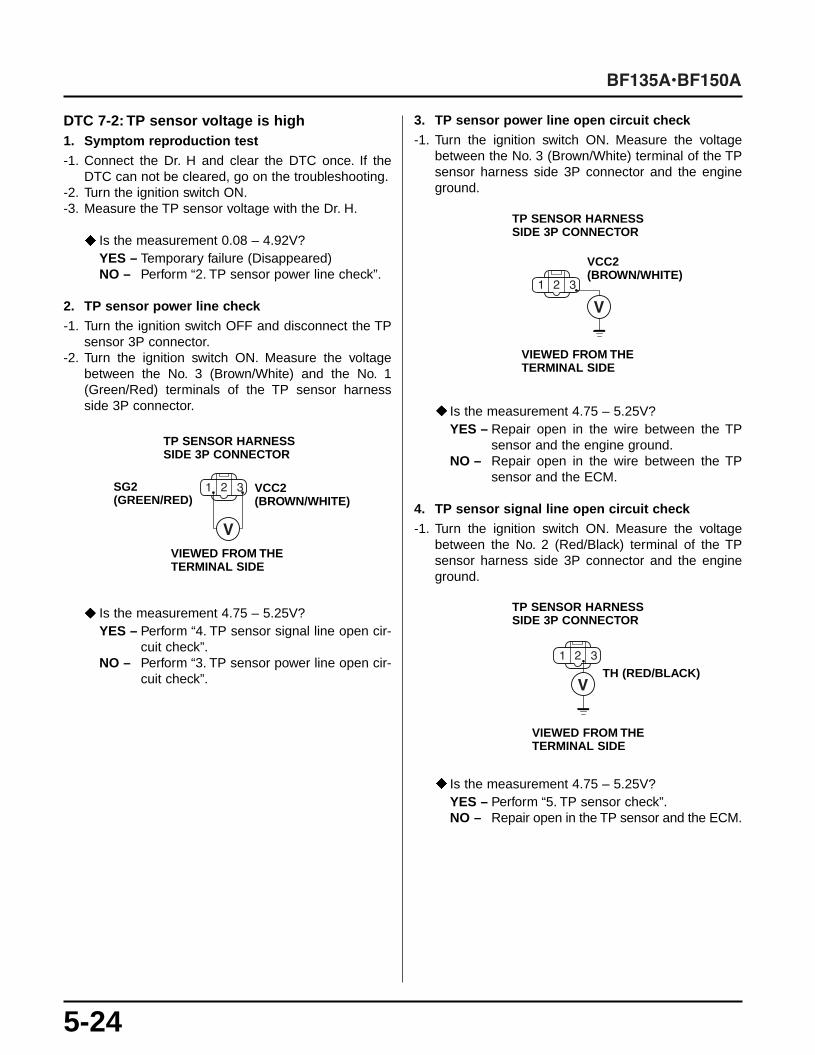
DTC 7-2: TP sensor voltage is high1. Symptom reproduction test-1. Connect the Dr. H and clear the DTC once. If the
DTC can not be cleared, go on the troubleshooting.-2. Turn the ignition switch ON.-3. Measure the TP sensor voltage with the Dr. H.
Is the measurement 0.08 – 4.92V?YES – Temporary failure (Disappeared)NO – Perform “2. TP sensor power line check”.
2. TP sensor power line check-1. Turn the ignition switch OFF and disconnect the TP
sensor 3P connector.-2. Turn the ignition switch ON. Measure the voltage
between the No. 3 (Brown/White) and the No. 1(Green/Red) terminals of the TP sensor harnessside 3P connector.
Is the measurement 4.75 – 5.25V?YES – Perform “4. TP sensor signal line open cir-
cuit check”.NO – Perform “3. TP sensor power line open cir-
cuit check”.
3. TP sensor power line open circuit check-1. Turn the ignition switch ON. Measure the voltage
between the No. 3 (Brown/White) terminal of the TPsensor harness side 3P connector and the engineground.
Is the measurement 4.75 – 5.25V?YES – Repair open in the wire between the TP
sensor and the engine ground.NO – Repair open in the wire between the TP
sensor and the ECM.
4. TP sensor signal line open circuit check-1. Turn the ignition switch ON. Measure the voltage
between the No. 2 (Red/Black) terminal of the TPsensor harness side 3P connector and the engineground.
Is the measurement 4.75 – 5.25V?YES – Perform “5. TP sensor check”.NO – Repair open in the TP sensor and the ECM.
TP SENSOR HARNESSSIDE 3P CONNECTOR
VCC2 (BROWN/WHITE)
SG2(GREEN/RED)
VIEWED FROM THETERMINAL SIDE
TP SENSOR HARNESSSIDE 3P CONNECTOR
VCC2 (BROWN/WHITE)
VIEWED FROM THETERMINAL SIDE
TP SENSOR HARNESSSIDE 3P CONNECTOR
TH (RED/BLACK)
VIEWED FROM THETERMINAL SIDE

5-25
5. TP sensor check-1. Turn the ignition switch OFF and connect the TP
sensor 3P connector.-2. Measure the TP sensor voltage using the Dr. H.
Is the measurement voltage 4.49 – 4.85V at fullopen throttle and 0.44 – 0.56V at full close throttle?YES – Substitute a known-good ECM and recheck.NO – Replace the TP sensor.
• CMP Sensor TroubleshootingDTC 8-1: No CMP sensor pulse1. Symptom reproduction test-1. Connect the Dr. H and clear the DTC once. If the
DTC can not be cleared, go on the troubleshooting.-2. Start the engine and let it run at idling under no load.-3. Check the DTC using the Dr. H.
Does the DTC 8-1 appear?YES – Check the pulse plate. If it is normal, per-
form “2. CMP sensor power line check”. If itis abnormal, replace the pulse plate andrecheck.
NO – Temporary failure (Disappeared)
2. CMP sensor power line check-1. Turn the ignition switch OFF and disconnect the
CMP sensor 3P connector.-2. Turn the ignition switch ON. Measure the voltage
between the No. 1 (Yellow/Black) terminal and theNo. 2 (Green/Red) terminal of the CMP sensor har-ness side 3P connector.
Is there the battery voltage?YES – Perform “4. CMP sensor signal line open
circuit check”.NO – Perform “3. CMP sensor power line open
circuit check”.
CMP SENSOR HARNESSSIDE 3P CONNECTOR
LG1 (GREEN/RED)
IGP(YELLOW/BLACK)
VIEWED FROM THETERMINAL SIDE

5-26
3. CMP sensor power line open circuit check-1. Turn the ignition switch ON. Measure the voltage
between the No. 1 (Yellow/Black) terminal of theCMP sensor harness side 3P connector and theengine ground.
Is there the battery voltage?YES – Repair open in the CMP sensor ground line.NO – Repair open in the wire between the No. 4
fuse and the CMP sensor.
4. CMP sensor signal line open circuit check-1. Turn the ignition switch ON. Measure the voltage
between the No. 3 (Green) terminal of the CMP sensorharness side 3P connector and the engine ground.
Is the measurement voltage 4.75 – 5.25V?YES – Perform “5. CMP sensor check”.NO – Repair open in the wire between the CMP
sensor and the ECM.
5. CMP sensor check-1. Connect the Dr. H and clear the DTC once.-2. Start the engine and let it run at idling under no load.
Check the DTC using the Dr. H.
Does the DTC 8-1 appear?YES – Replace the CMP sensor and recheck. If
the DTC 8-1 appears again, substitute aknown-good ECM and recheck.
NO – End of the check
DTC 8-2: CMP sensor pulse is abnormal1. Symptom reproduction test-1. Connect the Dr. H and clear the DTC once. If the
DTC can not be cleared, go on the troubleshooting.-2. Start the engine and let it run at idling under no load.-3. Check the DTC using the Dr. H.
Does the DTC 8-2 appear?YES – Replace the CMP sensor and recheck. If
the DTC 8-2 appears again, substitute aknown-good ECM and recheck.
NO – Temporary failure (Disappeared)
CMP SENSOR HARNESSSIDE 3P CONNECTOR
IGP(YELLOW/BLACK)
VIEWED FROM THETERMINAL SIDE
CMP SENSOR HARNESSSIDE 3P CONNECTOR
TDC (GREEN)
VIEWED FROM THETERMINAL SIDE
5-27
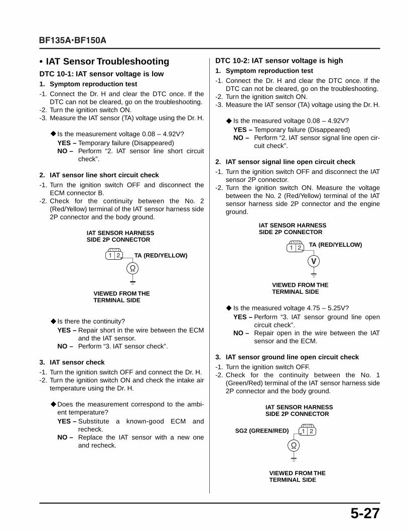
• IAT Sensor TroubleshootingDTC 10-1: IAT sensor voltage is low1. Symptom reproduction test-1. Connect the Dr. H and clear the DTC once. If the
DTC can not be cleared, go on the troubleshooting.-2. Turn the ignition switch ON.-3. Measure the IAT sensor (TA) voltage using the Dr. H.
Is the measurement voltage 0.08 – 4.92V?YES – Temporary failure (Disappeared)NO – Perform “2. IAT sensor line short circuit
check”.
2. IAT sensor line short circuit check-1. Turn the ignition switch OFF and disconnect the
ECM connector B.-2. Check for the continuity between the No. 2
(Red/Yellow) terminal of the IAT sensor harness side2P connector and the body ground.
Is there the continuity?YES – Repair short in the wire between the ECM
and the IAT sensor.NO – Perform “3. IAT sensor check”.
3. IAT sensor check-1. Turn the ignition switch OFF and connect the Dr. H.-2. Turn the ignition switch ON and check the intake air
temperature using the Dr. H.
Does the measurement correspond to the ambi-ent temperature?YES – Substitute a known-good ECM and
recheck.NO – Replace the IAT sensor with a new one
and recheck.
DTC 10-2: IAT sensor voltage is high1. Symptom reproduction test-1. Connect the Dr. H and clear the DTC once. If the
DTC can not be cleared, go on the troubleshooting.-2. Turn the ignition switch ON.-3. Measure the IAT sensor (TA) voltage using the Dr. H.
Is the measured voltage 0.08 – 4.92V?YES – Temporary failure (Disappeared)NO – Perform “2. IAT sensor signal line open cir-
cuit check”.
2. IAT sensor signal line open circuit check-1. Turn the ignition switch OFF and disconnect the IAT
sensor 2P connector.-2. Turn the ignition switch ON. Measure the voltage
between the No. 2 (Red/Yellow) terminal of the IATsensor harness side 2P connector and the engineground.
Is the measured voltage 4.75 – 5.25V?YES – Perform “3. IAT sensor ground line open
circuit check”.NO – Repair open in the wire between the IAT
sensor and the ECM.
3. IAT sensor ground line open circuit check-1. Turn the ignition switch OFF.-2. Check for the continuity between the No. 1
(Green/Red) terminal of the IAT sensor harness side2P connector and the body ground.
IAT SENSOR HARNESSSIDE 2P CONNECTOR
TA (RED/YELLOW)
VIEWED FROM THETERMINAL SIDE
IAT SENSOR HARNESSSIDE 2P CONNECTOR
VIEWED FROM THETERMINAL SIDE
IAT SENSOR HARNESSSIDE 2P CONNECTOR
SG2 (GREEN/RED)
VIEWED FROM THETERMINAL SIDE
TA (RED/YELLOW)

5-28
Is there the continuity?YES – Perform “4. IAT sensor check”.NO – Repair open in the wire between the IAT
sensor and the engine ground.
4. IAT sensor check-1. Turn the ignition switch OFF and connect the Dr. H.-2. Turn the ignition switch ON and check the intake air
temperature using the Dr. H.
Does the measurement correspond to the ambi-ent temperature?YES – Substitute a known-good ECM and recheck.NO – Substitute a known-good IAT sensor and
recheck.
• BARO Sensor TroubleshootingDTC 13-1: BARO sensor voltage is low1. Symptom reproduction test-1. Connect the Dr. H and clear the DTC once. If the
DTC can not be cleared, go on the troubleshooting.-2. Turn the ignition switch ON.-3. Measure the BARO sensor (PA) voltage using the
Dr. H.
Is the measurement voltage 1.58 – 4.49V?YES – Temporary failure (Disappeared)NO – Perform “2. BARO sensor signal line short
circuit check”.
2. BARO sensor signal line short circuit check-1. Turn the ignition switch OFF and disconnect the
ECM connector B.-2. Check for the continuity between the No. 2
(White/Blue) terminal of the BARO sensor harnessside 3P connector and the body ground.
Is there the continuity?YES – Repair short in the wire between the ECM
and the BARO sensor.NO – Perform “3. BARO sensor check”.
3. BARO sensor check-1. Turn the ignition switch OFF and connect the BARO
sensor connector and the ECM connector B.-2. Turn the ignition switch ON. Measure the BARO sen-
sor voltage using the Dr. H.
Is the measurement voltage 2.76 – 2.96V?YES – Substitute a known-good ECM and recheck.NO – Replace the BARO sensor and recheck.
BARO SENSOR HARNESSSIDE 3P CONNECTOR
PA (WHITE/BLUE)
VIEWED FROM THETERMINAL SIDE

5-29
DTC 13-2: BARO sensor voltage is high1. Symptom reproduction test-1. Connect the Dr. H and clear the DTC once. If the
DTC can not be cleared, go on the troubleshooting.-2. Turn the ignition switch ON.-3. Measure the BARO sensor (PA) voltage using the
Dr. H.
Is the measurement voltage 1.58 – 4.49V?YES – Temporary failure (Disappeared)NO – Perform “2. BARO sensor power line check”.
2. BARO sensor power line check-1. Turn the ignition switch OFF and disconnect the
BARO sensor 3P connector.-2. Turn the ignition switch ON. Measure the voltage
between the No. 3 (Brown/White) and the No. 1(Green/Red) terminals of the BARO sensor harnessside 3P connector.
Is the measurement voltage 4.75 – 5.25V?YES – Perform “4. BARO sensor signal line open
circuit check”.NO – Perform “3. BARO sensor power line open
circuit check”.
3. BARO sensor power line open circuit check-1. Turn the ignition switch ON. Measure the voltage
between the No. 3 (Brown/White) terminal of theBARO sensor harness side 3P connector and theengine ground.
Is the measured voltage 4.75 – 5.25V?YES – Repair open in the wire between the BARO
sensor and the engine ground.NO – Repair open in the wire between the BARO
sensor and the ECM.
4. BARO sensor signal line open circuit check-1. Turn the ignition switch ON. Measure the voltage
between the No. 2 (White/Blue) terminal of theBARO sensor harness side 3P connector and theengine ground.
Is the measured voltage 4.75 – 5.25V?YES – Perform “5. BARO sensor check”.NO – Repair open in the wire between the BARO
sensor and the ECM.
5. BARO sensor check-1. Turn the ignition switch OFF and connect the BARO
sensor connector.-2. Turn the ignition switch ON and measure the BARO
sensor voltage using the Dr. H.
Is the measured voltage 2.76 – 2.96V?YES – Substitute a known-good ECM and recheck.NO – Replace the BARO sensor and recheck.
BARO SENSOR HARNESSSIDE 3P CONNECTOR
SG2(GREEN/RED)
VCC2(BROWN/WHITE)
VIEWED FROM THETERMINAL SIDE
BARO SENSOR HARNESSSIDE 3P CONNECTOR
VCC2 (BROWN/WHITE)
VIEWED FROM THETERMINAL SIDE
BARO SENSOR HARNESSSIDE 3P CONNECTOR
PA (WHITE/BLUE)
VIEWED FROM THETERMINAL SIDE

5-30
• IAC Valve TroubleshootingDTC 14-1: IAC valve current is abnormal1. Symptom reproduction test-1. Connect the Dr. H and clear the DTC once. If the
DTC can not be cleared, go on the troubleshooting.-2. Start the engine and let it run at idling under no load.-3. Measure the engine speed using the Dr. H.
Is the engine speed 650 min-1 (rpm) or above?YES – Temporary failure (Disappeared)NO – Perform “2. IAC valve open circuit check”.
2. IAC valve open circuit check-1. Turn the ignition switch OFF and disconnect the IAC
valve 2P connector.-2. Measure the resistance between the No. 1 and No. 2
terminals of the IAC valve.
Is the measured resistance 8 – 12 ?YES – Perform “3. IAC valve short circuit check”.NO – Replace the IAC valve.
3. IAC valve short circuit check-1. Check for the continuity between the IAC valve No. 1
terminal and the body ground.
Is there the continuity?YES – Replace the IAC valve.NO – Go to the step 2.
-2. Check for the continuity between the IAC valve No. 2terminal and the body ground.
Is there the continuity?YES – Replace the IAC valve.NO – Perform “4. IAC valve line open circuit
check”.
4. IAC valve line open circuit check-1. Connect the IAC valve 2P connector.-2. Disconnect the ECM connector B.-3. Measure the resistance between the No. 26
(Green/White) and the No. 34 (Black) terminals ofthe ECM connector B.
Is the measured resistance 10 – 13 ?YES – Perform “5. IAC valve line short circuit
check”.NO – Repair open in the wire between the ECM
and the IAC valve.
IAC VALVE SIDE 2PCONNECTOR
VIEWED FROM THETERMINAL SIDE
IAC VALVE SIDE 2PCONNECTOR
VIEWED FROM THETERMINAL SIDE
IAC VALVE SIDE 2PCONNECTOR
VIEWED FROM THETERMINAL SIDE
ECM CONNECTOR B
VIEWED FROM THETERMINAL SIDE
EACVM(BLACK)
EACVP(GREEN/WHITE)

5-31
5. IAC valve line short circuit check-1. Check for the continuity between the No. 26
(Green/White) terminal of the ECM connector B andthe engine ground, and between the No. 34 (Black)terminal of the ECM connector B and the engineground.
Is there the continuity?YES – Repair short in the wire between the ECM
and the IAC valve.NO – Substitute a known-good ECM and recheck.
• VTEC Solenoid Valve TroubleshootingDTC 21-1:VTEC solenoid valve output is abnormal1. Symptom reproduction test-1. Connect the Dr. H and clear the DTC once. If the
DTC can not be cleared, go on the troubleshooting.-2. Start the engine and warm it up for 5 minutes by run-
ning the engine at 3,000 min-1 (rpm) under no load.-3. Disconnect the neutral switch 2P connector.-4. Increase the engine speed gradually and run the
engine at 4,500 min-1 (rpm) for a few seconds.-5. Check the DTC again using the Dr. H.
Does the DTC 21-1 appear?YES – Perform “2. Spool solenoid valve check”.NO – Temporary failure (Disappeared)
2. Spool solenoid valve check-1. Turn the ignition switch OFF and disconnect the
spool solenoid valve connector.-2. Measure the resistance between the spool solenoid
valve side 1P connector (Green/White) terminal andthe body ground.
Is the measured resistance 12 – 18 ?YES – Perform “3. VTEC signal line short circuit
check”.NO – Replace the spool solenoid valve.
ECM CONNECTOR B
VIEWED FROM THETERMINAL SIDE
SOLENOID VALVE SIDE1P CONNECTOR
VIEWED FROM THETERMINAL SIDE
EACVM(BLACK)
EACVP(GREEN/WHITE)
5-32
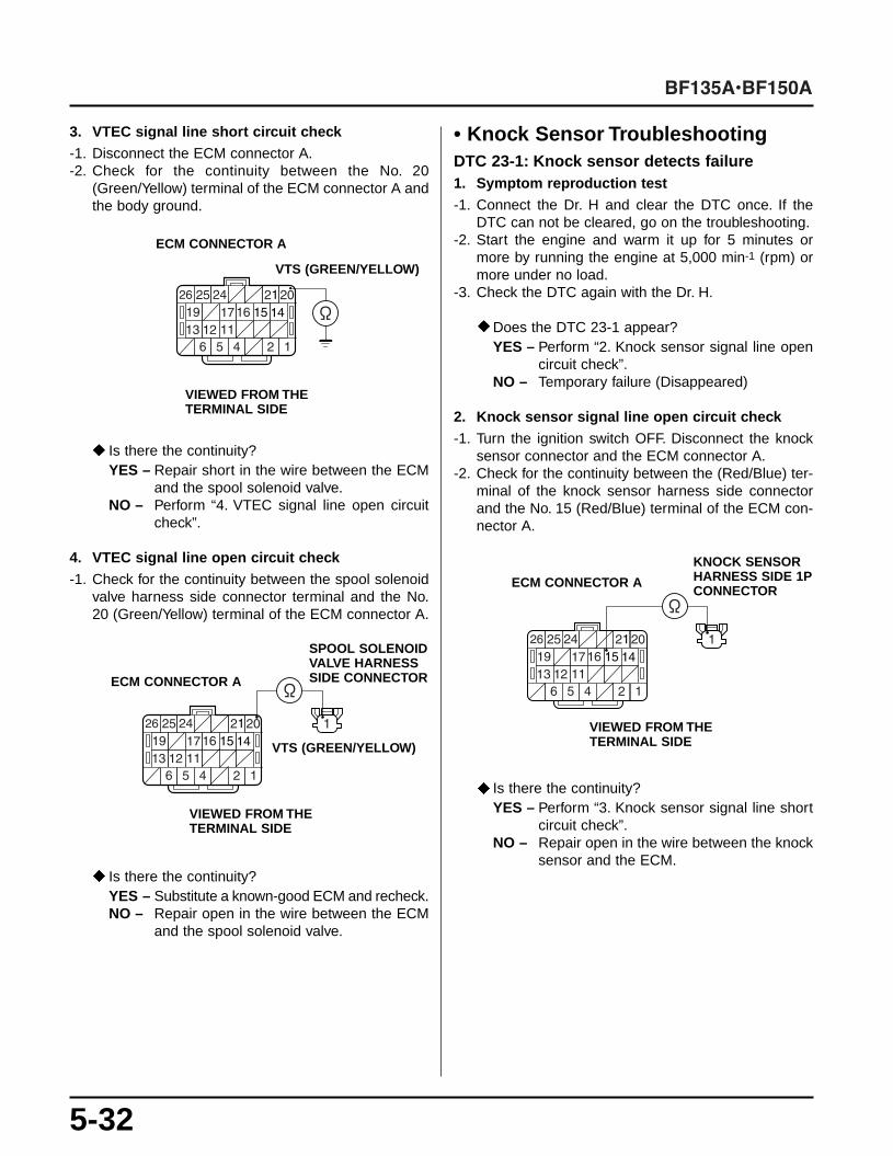
3. VTEC signal line short circuit check-1. Disconnect the ECM connector A.-2. Check for the continuity between the No. 20
(Green/Yellow) terminal of the ECM connector A andthe body ground.
Is there the continuity?YES – Repair short in the wire between the ECM
and the spool solenoid valve.NO – Perform “4. VTEC signal line open circuit
check”.
4. VTEC signal line open circuit check-1. Check for the continuity between the spool solenoid
valve harness side connector terminal and the No.20 (Green/Yellow) terminal of the ECM connector A.
Is there the continuity?YES – Substitute a known-good ECM and recheck.NO – Repair open in the wire between the ECM
and the spool solenoid valve.
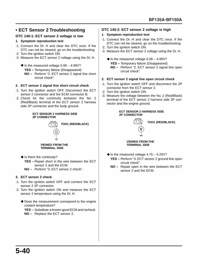
• Knock Sensor TroubleshootingDTC 23-1: Knock sensor detects failure1. Symptom reproduction test-1. Connect the Dr. H and clear the DTC once. If the
DTC can not be cleared, go on the troubleshooting.-2. Start the engine and warm it up for 5 minutes or
more by running the engine at 5,000 min-1 (rpm) ormore under no load.
-3. Check the DTC again with the Dr. H.
Does the DTC 23-1 appear?YES – Perform “2. Knock sensor signal line open
circuit check”.NO – Temporary failure (Disappeared)
2. Knock sensor signal line open circuit check-1. Turn the ignition switch OFF. Disconnect the knock
sensor connector and the ECM connector A.-2. Check for the continuity between the (Red/Blue) ter-
minal of the knock sensor harness side connectorand the No. 15 (Red/Blue) terminal of the ECM con-nector A.
Is there the continuity?YES – Perform “3. Knock sensor signal line short
circuit check”.NO – Repair open in the wire between the knock
sensor and the ECM.
ECM CONNECTOR A
VIEWED FROM THETERMINAL SIDE
VTS (GREEN/YELLOW)
SPOOL SOLENOIDVALVE HARNESSSIDE CONNECTORECM CONNECTOR A
VTS (GREEN/YELLOW)
VIEWED FROM THETERMINAL SIDE
KNOCK SENSORHARNESS SIDE 1PCONNECTOR
ECM CONNECTOR A
VIEWED FROM THETERMINAL SIDE

5-33
3. Knock sensor signal line short circuit test-1. Check for the continuity between the No. 15
(Red/Blue) terminal of the ECM connector A and thebody ground.
Is there the continuity?YES – Repair short in the wire between the ECM
and the spool solenoid valve.NO – Substitute a known-good ECM and recheck.
• A/F Heater TroubleshootingDTC 41-3: A/F heater is abnormal1. Symptom reproduction test-1. Connect the Dr. H and clear the DTC once. If the
DTC can not be cleared, go on the troubleshooting.-2. Start the engine and warm it up 5 minutes or more by
running the engine at 3,000 min-1 (rpm) under no load.-3. Check the DTC again using the Dr. H.
Does the DTC 41-3 appear?YES – Perform “2. A/F heater relay check”.NO – Temporary failure (Disappeared)
2. A/F heater relay check-1. Turn the ignition switch OFF and disconnect the A/F
sensor 4P connector.-2. Turn the ignition switch ON. Measure the voltage
between the No. 3 (White) terminal of the A/F sensorharness side 4P connector and the engine ground.
Is there the battery voltage?YES – Perform “3. A/F sensor heater check”.NO – Go to the step 3.
-3. Turn the ignition switch OFF and disconnect the A/Fheater relay 4P connector.
-4. Measure the voltage between the No. 1 (White/Green) terminal of the A/F heater relay harness side4P connector and the engine ground.• Note that the battery voltage is constantly applied
to the White/Green terminal. Take care not to short-circuit the terminal.
ECM CONNECTOR A
VIEWED FROM THETERMINAL SIDE
KS (RED/BLUE)
A/F SENSOR HARNESSSIDE 4P CONNECTOR
VIEWED FROM THE TERMINAL SIDE
AFHT+ (WHITE)
A/F HEATER RELAY HARNESSSIDE 4P CONNECTOR
VIEWED FROM THETERMINAL SIDE
+B (WHITE/GREEN)

5-34
Is there the battery voltage?YES – Go to the step 5.NO – Blown No. 1 fuse, or repair open in the wire
between the A/F heater relay and the No. 1fuse.
-5. Turn the ignition switch ON. Measure the voltagebetween the No. 3 (White) terminal of the A/F heaterrelay harness side 4P connector and the engine ground.
Is there the battery voltage?YES – Go to the step 6.NO – Repair open in the wire between the A/F
heater relay and the No. 5 fuse.
-6. Check the A/F heater relay (P. 18-20 of the base manual).
Is the A/F heater relay normal?YES – Go to the step 7.NO – Replace the A/F heater relay.
-7. Turn the ignition switch OFF and disconnect theECM connector A.
-8. Check for the continuity between the No. 4 (Green/Orange) terminal of the A/F heater relay harnessside 4P connector and the No. 25 (Green/Orange)terminal of the ECM connector A.
Is there the continuity?YES – Go to the step 9.NO – Repair open in the wire between the A/F
heater relay and the ECM.
-9. Check for the continuity between the No. 3 (White)terminal of the A/F heater relay harness side 4P con-nector and the No. 3 (White) terminal of the A/F sen-sor harness side 4P connector.
Is there the continuity?YES – Perform “3. A/F sensor heater check”.NO – Repair open in the wire between the A/F
heater relay and the A/F sensor.
3. A/F sensor heater check-1. Turn the ignition switch OFF and disconnect the A/F
sensor 4P connector.-2. Measure the resistance between the No. 3 (Black)
and the No. 4 (Black) terminals of the A/F sensorside 4P connector.
Is the resistance 2 – 3 (at room temperature)?YES – Perform “4. Heater line short circuit check”.NO – Replace the A/F sensor.
A/F HEATER RELAY HARNESSSIDE 4P CONNECTOR
VIEWED FROM THETERMINAL SIDE
A/F HEATER RELAYHARNESS SIDE 4P CONNECTOR
VIEWED FROM THETERMINAL SIDE
AFHT-(GREEN/ORANGE)
ECM CONNECTOR A
A/F SENSOR HARNESSSIDE 4P CONNECTOR
A/F HEATER RELAYHARNESS SIDE 4P CONNECTOR
VIEWED FROM THETERMINAL SIDE
AFHT+ (WHITE) AFHT+ (WHITE)
AFHT+ (WHITE)
A/F SENSOR SIDE 4PCONNECTOR
VIEWED FROM THETERMINAL SIDE
AFHT (BLACK) AFHT+ (BLACK)

5-35
4. Heater line short circuit check-1. Turn the ignition switch OFF and disconnect the
ECM connector C.-2. Check for the continuity between the No. 3
(Black/White) terminal of the ECM connector C andthe engine ground, and between the No. 4 (White)terminal of the ECM connector C and the engineground.
Is there the continuity?YES – Repair short in the wire between the A/F
sensor and the ECM.NO – Perform “5. Heater line open circuit check”.
5. Heater line open circuit check-1. Turn the ignition switch OFF and connect the A/F
sensor 4P connector.-2. Measure the resistance between the No. 3
(Black/White) and the No. 4 (White) terminals of theECM connector C.
Is the resistance 2 – 3 (at room temperature)?YES – Replace the A/F sensor and recheck. If it is
still abnormal, substitute a known-goodECM and recheck.
NO – Repair open in the wire between the A/Fsensor and the ECM.
DTC 41-4: A/F sensor heater is abnormal1. Symptom reproduction test-1. Connect the Dr. H and clear the DTC once. If the
DTC can not be cleared, go on the troubleshooting.-2. Start the engine and warm it up for 5 minutes or
more by running the engine at 3,000 min-1 (rpm)under no load.
-3. Check the DTC again using the Dr. H.
Does the DTC 41-4 appear?YES – Perform “2. A/F heater relay check”.NO – Temporary failure (Disappeared)
2. A/F heater relay check-1. Turn the ignition switch OFF and disconnect the A/F
sensor 4P connector.-2. Turn the ignition switch ON. Measure the voltage
between the No. 3 (White) terminal of the A/F sensorharness side 4P connector and the engine ground.
Is there the battery voltage?YES – Perform “3. A/F heater harness check”.NO – Go to the step 3.
-3. Turn the ignition switch OFF and disconnect the A/Fheater relay 4P connector.
-4. Measure the voltage between the No. 1 (White/Green) terminal of the A/F heater relay harness side4P connector and the engine ground.
• Note that the battery voltage is constantlyapplied to the White/Green terminal. Take carenot to short-circuit the terminal.
VIEWED FROM THETERMINAL SIDE
A/F SENSOR HARNESSSIDE 4P CONNECTOR
VIEWED FROM THETERMINAL SIDE
AFHT+(WHITE)
A/F HEATER RELAY HARNESSSIDE 4P CONNECTOR
VIEWED FROM THE TERMINAL SIDE
+B (WHITE/GREEN)
ECM CONNECTOR C
ECM CONNECTOR C
AFHT(BLACK/WHITE)
AFHT+ (WHITE)
AFHT(BLACK/WHITE)
AFHT+ (WHITE)
VIEWED FROM THETERMINAL SIDE

5-36
Is there the battery voltage?YES – Go to the step 5.NO – Blown No. 1 fuse, or repair open in the wire
between the A/F heater relay and the No. 1fuse.
-5. Turn the ignition switch ON. Measure the voltagebetween the No. 3 (White) terminal of the A/F heaterrelay harness side 4P connector and the engine ground.
Is there the battery voltage?YES – Go to the step 6.NO – Repair open in the wire between the A/F
heater relay and the No. 5 fuse.
-6. Check the A/F heater relay (single unit check) (P. 18-24 of the base manual).
Is the A/F heater relay normal?YES – Go to the step 7.NO – Replace the A/F heater relay.
-7. Turn the ignition switch OFF and disconnect theECM connector A.
-8. Check for continuity between the No. 4 (Green/Orange) terminal of the A/F heater relay harnessside 4P connector and the No. 25 (Green/Orange)terminal of the ECM connector A.
Is there the continuity?YES – Go to the step 9.NO – Repair open in the wire between the A/F
heater relay and the ECM.
-9. Check for the continuity between the No. 3 (White)terminal of the A/F heater relay harness side 4P con-nector and the No. 3 (White) terminal of the A/F sen-sor harness side 4P connector.
Is there the continuity?YES – Perform “3. A/F heater check”.NO – Repair open in the wire between the A/F
heater relay and the A/F sensor.
3. A/F heater check-1. Turn the ignition switch OFF and disconnect the A/F
sensor 4P connector.-2. Measure the resistance between the No. 3 (Black)
and the No. 4 (Black) terminals of the A/F sensorside 4P connector.
Is the measured resistance 2 – 3 (at room tem-perature)?YES – Perform “4. Heater line short circuit check”.NO – Replace the A/F sensor.
A/F HEATER RELAY HARNESSSIDE 4P CONNECTOR
VIEWED FROM THETERMINAL SIDE
AFHT+ (WHITE)
A/F HEATER RELAYHARNESS SIDE 4P CONNECTOR
VIEWED FROM THETERMINAL SIDE
AFHT- (GREEN/ORANGE)
ECM CONNECTOR A
A/F SENSORHARNESS SIDE 4P CONNECTOR
A/F HEATER RELAYHARNESS SIDE 4P CONNECTOR
VIEWED FROM THETERMINAL SIDE
AFHT+(WHITE)
AFHT+(WHITE)
A/F SENSOR SIDE 4P CONNECTOR
VIEWED FROM THETERMINAL SIDE
AFHT (BLACK) AFHT+ (BLACK)

5-37
-3. Check for the continuity between the No. 3 (Black/White) terminal of the ECM connector C and therespective terminals of the No. 1 (White/Black) andthe No. 2 (Black/Yellow) terminals of the A/F sensorharness side 4P connector.
Is there the continuity?YES – Repair short in the wire between the A/F
sensor and the ECM.NO – Go to the step 4.
-4. Check for continuity between the No. 4 (White) ter-minal of the ECM connector C and the respectiveterminals of the No. 1 (White/Black) and the No. 2(Black/Yellow) terminals of the A/F sensor harnessside 4P connector.
Is there the continuity?YES – Repair short in the wire between the A/F
sensor and the ECM.NO – Replace the A/F sensor and recheck. If it is
still abnormal, substitute a known-goodECM and recheck.
4. Heater line short circuit check-1. Turn the ignition switch OFF and disconnect the
ECM connector C.-2. Check for the continuity between the No. 3
(Black/White) terminal of the ECM connector C andthe engine ground, and between the No. 4 (White)terminal of the ECM connector C and the engineground.
Is there the continuity?YES – Repair short in the wire between the A/F
sensor and the ECM.NO – Perform “5. Heater line open circuit check”.
5. Heater line open circuit check-1. Turn the ignition switch OFF and connect the A/F
sensor 4P connector.-2. Measure the resistance between the No. 3 (Black/
White) terminal and the No. 4 (White) terminal of theECM connector C.
Is the resistance 2 – 3 (at room temperature)?YES – Perform “6. Sensor line short circuit check”.NO – Repair open in the wire between the A/F
sensor and the ECM.
6. Sensor line short circuit check-1. Disconnect the ECM connector B.-2. Disconnect the A/F sensor 4P connector.
ECM CONNECTOR C
VIEWED FROM THETERMINAL SIDE
AFHT(BLACK/WHITE)
AFHT+(WHITE)
ECM CONNECTOR C
VIEWED FROM THETERMINAL SIDE
A/F SENSOR HARNESS SIDE 4P CONNECTOR
VIEWED FROM THETERMINAL SIDE
ECM CONNECTOR C
A/F SENSOR HARNESS SIDE 4P CONNECTOR
VIEWED FROM THETERMINAL SIDE
AFC1 (BLACK/YELLOW)
ECM CONNECTOR C
AFHT+(WHITE)
AFV1(WHITE/BLACK)
AFC1 (BLACK/YELLOW)
AFV1(WHITE/BLACK)
AFHT(BLACK/ WHITE)
AFHT(BLACK/WHITE)
AFHT+ (WHITE)

5-38
• A/F Sensor TroubleshootingDTC 48-5: A/F sensor current is abnormal1. Symptom reproduction test-1. Connect the Dr. H and clear the DTC once. If the
DTC can not be cleared, go on the troubleshooting.-2. Start the engine and warm it up for 5 minutes or
more by running the engine at 3,000 min-1 (rpm)under no load.
-3. Check the DTC again using the Dr. H.
Does the DTC 48-5 appear?YES – Perform “2. A/F sensor line open circuit
check”.NO – Temporary failure (Disappears)
2. A/F sensor line open circuit check-1. Turn the ignition switch OFF. Disconnect the A/F sen-
sor connector and the ECM connector A.-2. Check for the continuity between the No. 1
(White/Black) terminal of the A/F sensor harnessside 4P connector and the No. 4 (White/Black) ter-minal of the ECM connector A.
Is there the continuity?YES – Go to the step 3.NO – Repair open in the wire between the A/F
sensor and the ECM.
-3. Check for the continuity between the No. 2(Black/Yellow) terminal of the A/F sensor harnessside 4P connector and the No. 14 (Black/Yellow) ter-minal of the ECM connector A.
Is there the continuity?YES – Replace the A/F sensor and recheck. If
there is abnormality, substitute a known-good ECM and recheck.
NO – Repair open in the wire between the A/Fsensor and the ECM.
A/F SENSORHARNESS SIDE 4P CONNECTOR
VIEWED FROM THETERMINAL SIDE
ECM CONNECTOR A
AFV1 (WHITE/BLACK)
VIEWED FROM THETERMINAL SIDE
A/F SENSORHARNESS SIDE 4P CONNECTOR
ECM CONNECTOR A
AFC1(BLACK/YELLOW)

5-39
DTC 48-6: A/F sensor V current is abnormal1. Symptom reproduction test-1. Connect the Dr. H and clear the DTC once. If the
DTC can not be cleared, go on the troubleshooting.-2. Start the engine and warm it up 5 minutes or more
by running the engine at 3,000 min-1 (rpm) under noload.
-3. Check the DTC again using the Dr. H.
Does the DTC 48-6 appear?YES – Perform “2. A/F sensor line short circuit
check”.NO – Temporary failure (Disappeared)
2. A/F sensor line (V line) short circuit check-1. Turn the ignition switch OFF. Disconnect the A/F sen-
sor connector and the ECM connector A.-2. Check for the continuity between the No. 1
(White/Black) terminal of the A/F sensor harnessside 4P connector and the engine ground.
Is there the continuity?YES – Repair short in the wire between the A/F
sensor and the ECM.NO – Replace the A/F sensor and recheck. If
there is any abnormality, substitute aknown-good ECM and recheck.
DTC 48-7: A/F sensor C current is abnormal1. Symptom reproduction test-1. Connect the Dr. H and clear the DTC once. If the
DTC can not be cleared, go on the troubleshooting.-2. Start the engine and warm it up for 5 minutes or
more by running the engine at 3,000 min-1 (rpm)under no load.
-3. Check the DTC again using the Dr. H.
Does the DTC 48-7 appear?YES – Perform “2. A/F sensor line short circuit
check”.NO – Temporary failure (Disappeared)
2. A/F sensor line (C line) short circuit check-1. Turn the ignition switch OFF. Disconnect the A/F sen-
sor connector and the ECM connector A.-2. Check for the continuity between the No. 2
(Black/Yellow) terminal of the A/F sensor harnessside 4P connector and the engine ground.
Is there the continuity?YES – Repair short in the wire between the A/F
sensor and the ECM.NO – Replace the A/F sensor and recheck. If it is
abnormal, substitute a known-good ECMand recheck.
A/F SENSOR HARNESSSIDE 4P CONNECTOR
VIEWED FROM THETERMINAL SIDE
AFV1 (WHITE/BLACK)
A/F SENSOR HARNESS SIDE4P CONNECTOR
VIEWED FROM THETERMINAL SIDE
AFC1 (BLACK/YELLOW)
5-40
• ECT Sensor 2 TroubleshootingDTC 140-1: ECT sensor 2 voltage is low1. Symptom reproduction test-1. Connect the Dr. H and clear the DTC once. If the
DTC can not be cleared, go on the troubleshooting.-2. Turn the ignition switch ON.-3. Measure the ECT sensor 2 voltage using the Dr. H.
Is the measured voltage 0.08 – 4.99V?YES – Temporary failure (Disappeared)NO – Perform “2. ECT sensor 2 signal line short
circuit check”.
2. ECT sensor 2 signal line short circuit check-1. Turn the ignition switch OFF. Disconnect the ECT
sensor 2 connector and the ECM connector B.-2. Check for the continuity between the No. 2
(Red/Black) terminal of the ECT sensor 2 harnessside 2P connector and the body ground.
Is there the continuity?YES – Repair short in the wire between the ECT
sensor 2 and the ECM.NO – Perform “3. ECT sensor 2 check”.
3. ECT sensor 2 check-1. Turn the ignition switch OFF and connect the ECT
sensor 2 2P connector.-2. Turn the ignition switch ON and measure the ECT
sensor 2 temperature using the Dr. H.
Does the measurement correspond to the enginecoolant temperature?YES – Substitute a known-good ECM and recheck.NO – Replace the ECT sensor 2.
DTC 140-2: ECT sensor 2 voltage is high1. Symptom reproduction test-1. Connect the Dr. H and clear the DTC once. If the
DTC can not be cleared, go on the troubleshooting.-2. Turn the ignition switch ON.-3. Measure the ECT sensor 2 voltage using the Dr. H.
Is the measured voltage 0.08 – 4.99V?YES – Temporary failure (Disappeared)NO – Perform “2. ECT sensor 2 signal line open
circuit check”.
2. ECT sensor 2 signal line open circuit check-1. Turn the ignition switch OFF and disconnect the 2P
connector from the ECT sensor 2.-2. Turn the ignition switch ON.-3. Measure the voltage between the No. 2 (Red/Black)
terminal of the ECT sensor 2 harness side 2P con-nector and the engine ground.
Is the measured voltage 4.75 – 5.25V?YES – Perform “3. ECT sensor 2 ground line open
circuit check”.NO – Repair open in the wire between the ECT
sensor 2 and the ECM.
ECT SENSOR 2 HARNESS SIDE2P CONNECTOR
VIEWED FROM THETERMINAL SIDE
TOH1 (RED/BLACK)
ECT SENSOR 2 HARNESS SIDE2P CONNECTOR
VIEWED FROM THETERMINAL SIDE
TOH1 (RED/BLACK)

5-41
3. ECT sensor 2 ground line open circuit check-1. Connect the ECM connector B.-2. Check for the continuity between the No. 1 (Green/
Red) terminal of the ECT sensor 2 harness side 2Pconnector and the body ground.
Is there the continuity?YES – Perform “4. ECT sensor 2 check”.NO – Repair open in the wire between the ECT
sensor 2 and the engine ground.
4. ECT sensor 2 check-1. Turn the ignition switch OFF and connect all the con-
nectors.-2. Turn the ignition switch ON. Measure the ECT sen-
sor 2 temperature using the Dr. H.
Does the measurement correspond to the enginecoolant temperature?YES – Substitute a known-good ECM and recheck.NO – Replace the ECT sensor 2.
• ECT Sensor 3 TroubleshootingDTC 141-1: ECT sensor 3 voltage is low1. Symptom reproduction test-1. Connect the Dr. H and clear the DTC once. If the
DTC can not be cleared, go on the troubleshooting.-2. Turn the ignition switch ON.-3. Measure the ECT sensor 3 voltage using the Dr. H.
Is the measured voltage 0.08 – 4.99V?YES – Temporary failure (Disappeared)NO – Perform “2. ECT sensor 3 signal line short
circuit check”.
2. ECT sensor 3 signal line short circuit check-1. Turn the ignition switch OFF. Disconnect the ECT
sensor 3 connector and the ECM connector B.-2. Check for the continuity between the No. 2 terminal
(Red) of the ECT sensor 3 harness side 2P connec-tor and the body ground.
Is there the continuity?YES – Repair short in the wire between the ECT
sensor 3 and the ECM.NO – Perform “3. ECT sensor 3 check”.
3. ECT sensor 3 check-1. Turn the ignition switch OFF and connect the ECT
sensor 3 2P connector.-2. Turn the ignition switch ON and measure the ECT
sensor 3 temperature using the Dr. H.
Does the measurement agree with the enginecoolant temperature?YES – Substitute a known-good ECM and recheck.NO – Replace the ECT sensor 3.
ECT SENSOR 2 HARNESS SIDE2P CONNECTOR
VIEWED FROM THETERMINAL SIDE
SG2 (GREEN/RED)
ECT SENSOR 3 HARNESS SIDE2P CONNECTOR
VIEWED FROM THETERMINAL SIDE
TOH2 (RED)

5-42
DTC 141-2: ECT sensor 3 voltage is high1. Symptom reproduction test-1. Connect the Dr. H and clear the DTC once. If the
DTC can not be cleared, go on the troubleshooting.-2. Turn the ignition switch ON.-3. Measure the ECT sensor 3 voltage using the Dr. H.
Is the measured voltage 0.08 – 4.99V?YES – Temporary failure (Disappeared)NO – Perform “2. ECT sensor 3 signal line open
circuit check”.
2. ECT sensor 3 signal line open circuit check-1. Turn the ignition switch OFF and disconnect the 2P
connector from the ECT sensor 3.-2. Turn the ignition switch ON.-3. Measure the voltage between the No. 2 (Red) termi-
nal of the ECT sensor 3 harness side 2P connectorand the engine ground.
Is the measured voltage 4.75 – 5.25V?YES – Perform “3. ECT sensor 3 ground line open
circuit check”.NO – Repair open in the wire between the ECT
sensor 3 and the ECM.
3. ECT sensor 3 ground line open circuit check-1. Connect the ECM connector B.-2. Check for continuity between the No. 1 (Green/Red)
terminal of the ECT sensor 3 harness side 2P con-nector and the body ground.
Is there the continuity?YES – Perform “4. ECT sensor 3 check”.NO – Repair open in the wire between the ECT
sensor 3 and the engine ground.
4. ECT sensor 3 check-1. Turn the ignition switch OFF and connect all the con-
nectors.-2. Turn the ignition switch ON and measure the ECT
sensor 3 temperature using the Dr. H.
Does the measurement agree with the enginecoolant temperature?YES – When the DTC appears again, substitute a
known-good ECM and recheck.NO – Replace the ECT sensor 3.
ECT SENSOR 3 HARNESS SIDE2P CONNECTOR
VIEWED FROM THETERMINAL SIDE
TOH2 (RED)
ECT SENSOR 3 HARNESS SIDE2P CONNECTOR
VIEWED FROM THETERMINAL SIDE
SG2 (GREEN/RED)
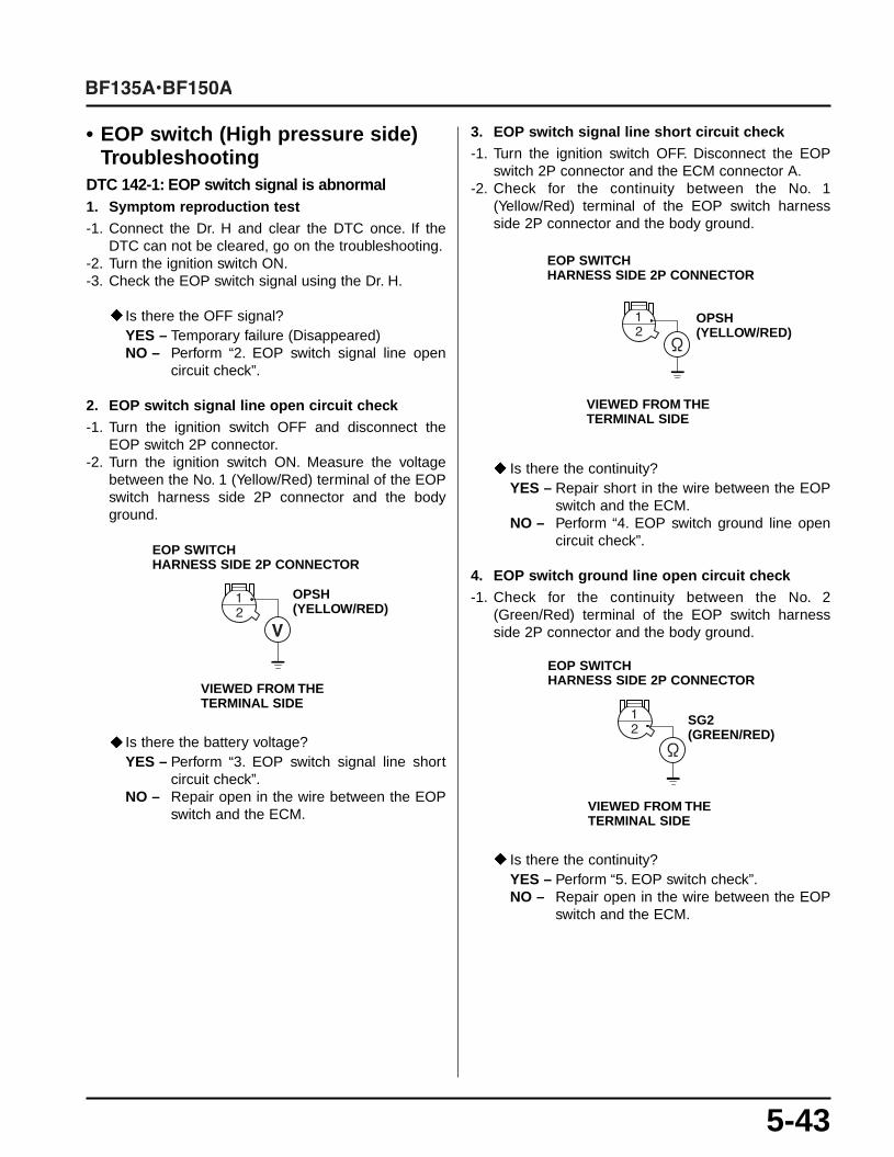
5-43
• EOP switch (High pressure side)Troubleshooting
DTC 142-1: EOP switch signal is abnormal1. Symptom reproduction test-1. Connect the Dr. H and clear the DTC once. If the
DTC can not be cleared, go on the troubleshooting.-2. Turn the ignition switch ON.-3. Check the EOP switch signal using the Dr. H.
Is there the OFF signal?YES – Temporary failure (Disappeared)NO – Perform “2. EOP switch signal line open
circuit check”.
2. EOP switch signal line open circuit check-1. Turn the ignition switch OFF and disconnect the
EOP switch 2P connector.-2. Turn the ignition switch ON. Measure the voltage
between the No. 1 (Yellow/Red) terminal of the EOPswitch harness side 2P connector and the bodyground.
Is there the battery voltage?YES – Perform “3. EOP switch signal line short
circuit check”.NO – Repair open in the wire between the EOP
switch and the ECM.
3. EOP switch signal line short circuit check-1. Turn the ignition switch OFF. Disconnect the EOP
switch 2P connector and the ECM connector A.-2. Check for the continuity between the No. 1
(Yellow/Red) terminal of the EOP switch harnessside 2P connector and the body ground.
Is there the continuity?YES – Repair short in the wire between the EOP
switch and the ECM.NO – Perform “4. EOP switch ground line open
circuit check”.
4. EOP switch ground line open circuit check-1. Check for the continuity between the No. 2
(Green/Red) terminal of the EOP switch harnessside 2P connector and the body ground.
Is there the continuity?YES – Perform “5. EOP switch check”.NO – Repair open in the wire between the EOP
switch and the ECM.
EOP SWITCHHARNESS SIDE 2P CONNECTOR
VIEWED FROM THETERMINAL SIDE
OPSH (YELLOW/RED)
EOP SWITCHHARNESS SIDE 2P CONNECTOR
VIEWED FROM THETERMINAL SIDE
OPSH (YELLOW/RED)
EOP SWITCHHARNESS SIDE 2P CONNECTOR
VIEWED FROM THETERMINAL SIDE
SG2 (GREEN/RED)

5-44
5. EOP switch check-1. Turn the ignition switch OFF and connect all the con-
nectors.-2. Turn the ignition switch ON and check the EOP
switch using the Dr. H.
Does the tester shows the switch OFF?YES – If the DTC appears again, substitute a
known-good ECM and recheck.NO – Replace the EOP switch.
• ECT Sensor 4 TroubleshootingDTC 143-1: ECT sensor 4 voltage is low1. Symptom reproduction test-1. Connect the Dr. H and clear the DTC once. If the
DTC can not be cleared, go on the troubleshooting.-2. Turn the ignition switch ON.-3. Measure the ECT sensor 4 voltage using the Dr. H.
Is the measured voltage 0.08 – 4.99V?YES – Temporary failure (Disappeared)NO – Perform “2. ECT sensor 4 signal line short
circuit check”.
2. ECT sensor 4 signal line short circuit check-1. Turn the ignition switch OFF. Disconnect the ECT
sensor 4 connector and the ECM connector B.-2. Check for the continuity between the No. 2
(Red/Green) terminal of the ECT sensor 4 harnessside connector and the body ground.
Is there the continuity?YES – Repair short in the wire between the ECT
sensor 4 and the ECM.NO – Perform “3. ECT sensor 4 check”.
3. ECT sensor 4 check-1. Turn the ignition switch OFF and connect the ECT
sensor 4 2P connector.-2. Turn the ignition switch ON. Measure the ECT sen-
sor 4 temperature using the Dr. H.
Does the measurement correspond to the enginecoolant temperature?YES – If the DTC appears again, substitute a
known-good ECM and recheck.NO – Replace the ECT sensor 4.
ECT SENSOR 4 HARNESS SIDE 2P CONNECTOR
VIEWED FROM THETERMINAL SIDE
TOH3 (RED/GREEN)

5-45
DTC 143-2: ECT sensor 4 voltage is high1. Symptom reproduction test-1. Connect the Dr. H and clear the DTC once. If the
DTC can not be cleared, go on the troubleshooting.-2. Turn the ignition switch ON.-3. Measure the ECT sensor 4 voltage using the Dr. H.
Is the measured voltage 0.08 – 4.99V?YES – Temporary failure (Disappeared)NO – Perform “2. ECT sensor 4 signal line open
circuit check”.
2. ECT sensor 4 signal line open circuit check-1. Turn the ignition switch OFF and disconnect the 2P
connector from the ECT sensor 4.-2. Turn the ignition switch ON.-3. Measure the voltage between the No. 2 (Red/Green)
terminal of the ECT sensor 4 harness side 2P con-nector and the engine ground.
Is the measured voltage 4.75 – 5.25V?YES – Perform “3. ECT sensor 4 ground line open
circuit check”.NO – Repair open in the wire between the ECT
sensor 4 and the ECM.
3. ECT sensor 4 ground line open circuit check-1. Connect the ECM connector B.-2. Check for the continuity between the No. 1
(Green/Red) terminal of the ECT sensor 4 harnessside 2P connector and the body ground.
Is there the continuity?YES – Perform “4. ECT sensor 4 check”.NO – Repair open in the wire between the ECT
sensor 4 and the engine ground.
4. ECT sensor 4 check-1. Turn the ignition switch OFF and connect all the con-
nectors.-2. Turn the ignition switch ON and measure the ECT
sensor 4 temperature using the Dr. H.
Does the measurement correspond to the enginecoolant temperature?YES – When the DTC appears again, substitute a
known-good ECM and recheck.NO – Replace the ECT sensor 4.
ECT SENSOR 4 HARNESS SIDE 2P CONNECTOR
VIEWED FROM THETERMINAL SIDE
TOH3 (RED/GREEN)
ECT SENSOR 4 HARNESS SIDE2P CONNECTOR
VIEWED FROM THETERMINAL SIDE
SG2 (GREEN/RED)

2008
66ZY600Z
2008.02