bevel gear - springer978-3-662-43893-0/1.pdfpreface in all textbooks ongear technology,cylindrical...
TRANSCRIPT

Bevel Gear

ThiS is a FM Blank Page
Jan Klingelnberg
Editor
Bevel Gear
Fundamentals and Applications
EditorJan KlingelnbergKlingelnberg GmbHPeterstraße 45, 42499HuckeswagenGermany
ISBN 978-3-662-43892-3 ISBN 978-3-662-43893-0 (eBook)DOI 10.1007/978-3-662-43893-0
Library of Congress Control Number: 2015949639
© Springer-Verlag Berlin Heidelberg 2016This work is subject to copyright. All rights are reserved by the Publisher, whether the whole or part ofthe material is concerned, specifically the rights of translation, reprinting, reuse of illustrations,recitation, broadcasting, reproduction on microfilms or in any other physical way, and transmissionor information storage and retrieval, electronic adaptation, computer software, or by similar ordissimilar methodology now known or hereafter developed.The use of general descriptive names, registered names, trademarks, service marks, etc. in thispublication does not imply, even in the absence of a specific statement, that such names are exemptfrom the relevant protective laws and regulations and therefore free for general use.The publisher, the authors and the editors are safe to assume that the advice and information in thisbook are believed to be true and accurate at the date of publication. Neither the publisher nor theauthors or the editors give a warranty, express or implied, with respect to the material containedherein or for any errors or omissions that may have been made.
Printed on acid-free paper
This Springer Vieweg imprint is published by Springer NatureThe registered company is Springer-Verlag GmbH Berlin Heidelberg
Editorial team:Hartmuth Muller
Klingelnberg GmbH, Peterstraße 45, 42499 Huckeswagen, Germany
Joachim Thomas
ZG Hypoid GmbH, Georg-Kollmannsberger-Straße 3, D-85386 Eching-Dietersheim,
Germany
Hans-Jurgen Trapp
Klingelnberg GmbH, Peterstraße 45, 42499 Huckeswagen, Germany
Claude Gosselin Ing. Ph.D., Involute Simulation Softwares Inc., Quebec, Canada

Preface
In all textbooks on gear technology, cylindrical gears usually come to attention first
because of their wide use, whereas bevel gears are dealt with superficially. There-
fore, readers with a deep interest in bevel gears are not satisfied.
Although the essential differences between bevel and cylindrical gears are
always outlined, the true characteristics and features of bevel gears, and their
“three-dimensional” nature which varies along the face width, are not sufficiently
detailed.
In this book, a team of authors from academia and industry aims to provide a
comprehensive textbook on bevel gears.
After covering the major fields of application for these machine elements, this
book presents the geometrical attributes of bevel gears and the different cutting
methods based on gear theory.
The three-dimensional aspect of the gear teeth is treated in detail, with chapters
on tooth flank development, load capacity, and noise behaviour. Descriptions of
production processes and necessary technologies provide a knowledge base for
sound decision-making.
The aim of this textbook is to introduce the reader to all aspects of the complex
world of bevel gears and to present in detail and in understandable form the results
of rapid developments in recent years
I like to thank all the co-authors for their contributions and for sharing their
knowledge gained through many years of professional experience.
Huckeswagen, Germany Jan Klingelnberg
2016
v

ThiS is a FM Blank Page

Symbols and Units
Symbols Definition Units
A Auxiliary factor for dynamic factor –
AE Distance between contact points A and E (complete path of
contact)
mm
Am Area of the half of ellipse of contact pressure distribution over
the middle contact line
mm2
Ar Area of the half of ellipse of contact pressure distribution over
the root contact line
mm2
At Area of the half of ellipse of contact pressure distribution over
the tip contact line
mm2
a Hypoid offset mm
ap Hypoid offset in the pitch plane mm
arel Relative offset –
av Centre distance of virtual cylindrical gears mm
B Accuracy grade acc. ISO 17485 –
B Auxiliary factor for dynamic factor –
BM Thermal contact coefficient N
mm1=2m
1=2 s1=2K
b Minor half-axis of the contact ellipse mm
b Face width mm
b2eff Effective face width (wheel) mm
be Face width from calculation point to outside mm
bH Semi-width of Hertzian contact band mm
bi Face width from calculation point to inside mm
bv Face width of virtual cylindrical gears mm
bveff Effective face width of virtual cylindrical gears mm
Ca Tip relief μmCeff Effective tip relief μm
vii
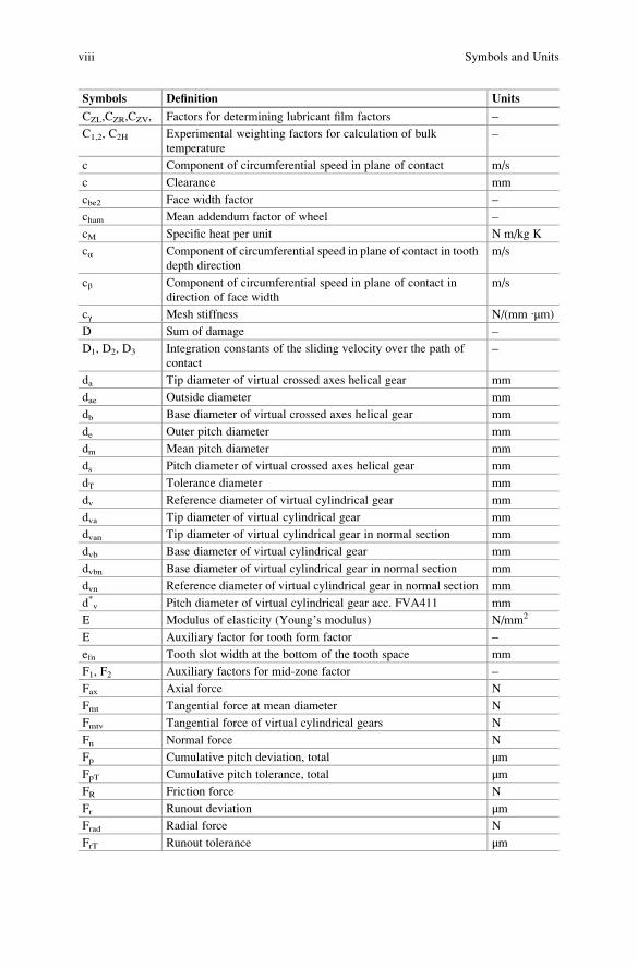
Symbols Definition Units
CZL,CZR,CZV, Factors for determining lubricant film factors –
C1,2, C2H Experimental weighting factors for calculation of bulk
temperature
–
c Component of circumferential speed in plane of contact m/s
c Clearance mm
cbe2 Face width factor –
cham Mean addendum factor of wheel –
cM Specific heat per unit N m/kg K
cα Component of circumferential speed in plane of contact in tooth
depth direction
m/s
cβ Component of circumferential speed in plane of contact in
direction of face width
m/s
cγ Mesh stiffness N/(mm ∙μm)
D Sum of damage –
D1, D2, D3 Integration constants of the sliding velocity over the path of
contact
–
da Tip diameter of virtual crossed axes helical gear mm
dae Outside diameter mm
db Base diameter of virtual crossed axes helical gear mm
de Outer pitch diameter mm
dm Mean pitch diameter mm
ds Pitch diameter of virtual crossed axes helical gear mm
dT Tolerance diameter mm
dv Reference diameter of virtual cylindrical gear mm
dva Tip diameter of virtual cylindrical gear mm
dvan Tip diameter of virtual cylindrical gear in normal section mm
dvb Base diameter of virtual cylindrical gear mm
dvbn Base diameter of virtual cylindrical gear in normal section mm
dvn Reference diameter of virtual cylindrical gear in normal section mm
d*v Pitch diameter of virtual cylindrical gear acc. FVA411 mm
E Modulus of elasticity (Young’s modulus) N/mm2
E Auxiliary factor for tooth form factor –
efn Tooth slot width at the bottom of the tooth space mm
F1, F2 Auxiliary factors for mid-zone factor –
Fax Axial force N
Fmt Tangential force at mean diameter N
Fmtv Tangential force of virtual cylindrical gears N
Fn Normal force N
Fp Cumulative pitch deviation, total μmFpT Cumulative pitch tolerance, total μmFR Friction force N
Fr Runout deviation μmFrad Radial force N
FrT Runout tolerance μm
viii Symbols and Units

Symbols Definition Units
Ft Tangential force N
Fx Index deviation μmF’i Single-flank composite deviation, total μrad/μmF”i Double-flank composite deviation, total μmF”r Double-flank runout deviation μmf Distance from mid-point M to any line of contact mm
fm Distance from mid-point M to the mean line of contact mm
fmax Maximum distance to the middle line of contact mm
fpt Single pitch deviation μmfptT Single pitch tolerance μmfαlim Influence factor of limit pressure angle –
fr Distance from mid-point M to the root line of contact mm
ft Distance from mid-point M to the tip line of contact mm
f’i Tooth-to-tooth single-flank composite deviation μrad/μmf’k Short-wave part of single-flank deviation μrad/μmf’l Long-wave part of single-flank deviation μrad/μmf”i Tooth-to-tooth double-flank composite deviation μmf”e Eccentricity of double-flank composite deviation μmG Movement of axis in case of sliding mm
G Auxiliary factor for tooth form factor N
G Auxiliary value for integration of sliding velocity over path of
contact
–
gan Length of the addendum part of the path of contact in the
normal section
mm
gfn Length of the dedendum part of the path of contact in the
normal section
mm
gn Distance of a contact point to the pitch or helix point on the
contact line in the normal plane
mm
gt Distance of a contact point to the pitch or helix point on the
contact line in the pitch plane
mm
gvα Length of the path of contact of virtual cylindrical gears mm
gvαn Length of the path of contact of virtual cylindrical gears in the
normal section
mm
H Auxiliary factor for tooth form factor –
HB Brinell hardness –
HRC Rockwell hardness –
HV Vickers hardness –
HV Tooth mesh loss factor –
hae Outer addendum mm
ham Mean addendum mm
hamc Mean chordal addendum mm
ha0 Tool addendum mm
hfe Outer dedendum mm
hfi Inner dedendum mm
Symbols and Units ix

Symbols Definition Units
hfm Mean dedendum mm
hFa Arm of the bending moment for tooth root stress
(load application at tooth tip)
mm
hm Mean whole depth mm
hmw Mean working depth mm
ht1 Pinion whole depth perpendicular to root cone mm
h1, h2 Auxiliary variables to determine the sliding velocity –
I Integral of sliding velocity distribution –
jen Outer normal backlash mm
jet Outer transverse backlash mm
jmn Mean normal backlash mm
jmt Mean transverse backlash mm
KA Application factor –
KBα Transverse load factor for scuffing –
KBβ Face load factor for scuffing –
KF0 Lengthwise curvature factor for bending stress –
KFα Transverse load factor for bending stress –
KFβ Face load factor for bending stress –
Kgm Sliding factor for calculation of the friction coefficient –
KHα Transverse load factor for contact stress –
KHβ Face load factor for contact stress –
Kmp Number of mates meshing with the actual gear –
Kv Dynamic factor –
kc Clearance factor –
kd Depth factor –
khap Basic crown gear addendum factor (related to mmn) –
khfp Basic crown gear dedendum factor (related to mmn) –
kt Circular thickness factor –
k1, k2 Auxiliary constants for the calculation of tooth mesh loss factor –
L Auxiliary factor for the calculation of the dimensions of the
contact ellipse
–
La Auxiliary factor for correction factor –
lb Length of contact line mm
lbm Theoretical length of middle line of contact mm
l’bm Projected length of middle line of contact in consideration of
inclined lines of contact
mm
met Outer transverse module mm
mmn Mean normal module mm
mmt Mean transverse module mm
msn Normal module of the virtual crossed axes helical gear mm
NL, NI Number of load cycles –
n Rotational speed 1/min
nI Number of load cycles of class I –
np Number of mates meshing with the actual gear –
x Symbols and Units

Symbols Definition Units
P Nominal power W
pe Base pitch mm
pen Normal base pitch mm
pet Transverse base pitch mm
p* Related peak load –
qs Notch parameter –
R Movement of axis in case of rolling mm
Ra ¼ CLA ¼ AA arithmetic average roughness μmRe Outer cone distance mm
Ri Inner cone distance mm
Rm Mean cone distance mm
Rz Mean roughness μmR Distance of a point on a contact line to the helix axis mm
rc0 Tool radius mm
rs Half diameter of crossed axes helical gear mm
SA Distance of contact points S and A at the contact line of the
virtual crossed axes helical gear
mm
SB Safety factor for scuffing (contact temperature method) –
SE Distance between contact points S and E at the contact line of
the virtual crossed axes helical gear
mm
SF Safety factor for bending stress (against breakage) –
SF min Minimum safety factor for bending stress –
SFZG Load stage in FZG- A/8,3/90-test –
SH Safety factor for contact stress (against pitting) –
SH min Minimum safety factor for contact stress –
Sint S Safety factor for scuffing acc. integral temperature method –
SS min Minimum required safety factor for scuffing –
sFn Tooth root chord in calculation section mm
smn Mean normal circular tooth thickness mm
smnc Mean normal chordal tooth thickness mm
spr Amount of protuberance mm
T Torque Nm
T1T Torque of load stage of the scuffing test Nm
tB Mounting distance mm
txi Front crown to crossing point mm
txo Crown to crossing point (hypoid) mm
tz Pitch apex beyond crossing point mm
tzF Face apex beyond crossing point mm
tzi Crossing point to inside point along axis mm
tzm Crossing point to mean point along axis mm
tzR Root apex beyond crossing point mm
U Voltage V
u Gear ratio –
ua Equivalent gear ratio –
Symbols and Units xi
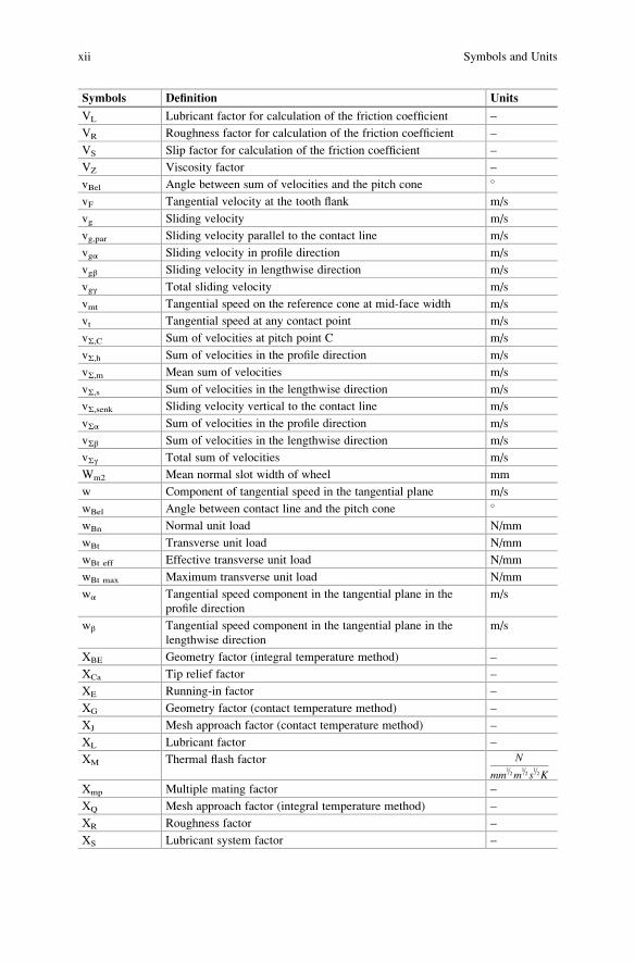
Symbols Definition Units
VL Lubricant factor for calculation of the friction coefficient –
VR Roughness factor for calculation of the friction coefficient –
VS Slip factor for calculation of the friction coefficient –
VZ Viscosity factor –
vBel Angle between sum of velocities and the pitch cone �
vF Tangential velocity at the tooth flank m/s
vg Sliding velocity m/s
vg,par Sliding velocity parallel to the contact line m/s
vgα Sliding velocity in profile direction m/s
vgβ Sliding velocity in lengthwise direction m/s
vgγ Total sliding velocity m/s
vmt Tangential speed on the reference cone at mid-face width m/s
vt Tangential speed at any contact point m/s
vΣ,C Sum of velocities at pitch point C m/s
vΣ,h Sum of velocities in the profile direction m/s
vΣ,m Mean sum of velocities m/s
vΣ,s Sum of velocities in the lengthwise direction m/s
vΣ,senk Sliding velocity vertical to the contact line m/s
vΣα Sum of velocities in the profile direction m/s
vΣβ Sum of velocities in the lengthwise direction m/s
vΣγ Total sum of velocities m/s
Wm2 Mean normal slot width of wheel mm
w Component of tangential speed in the tangential plane m/s
wBel Angle between contact line and the pitch cone �
wBn Normal unit load N/mm
wBt Transverse unit load N/mm
wBt eff Effective transverse unit load N/mm
wBt max Maximum transverse unit load N/mm
wα Tangential speed component in the tangential plane in the
profile direction
m/s
wβ Tangential speed component in the tangential plane in the
lengthwise direction
m/s
XBE Geometry factor (integral temperature method) –
XCa Tip relief factor –
XE Running-in factor –
XG Geometry factor (contact temperature method) –
XJ Mesh approach factor (contact temperature method) –
XL Lubricant factor –
XM Thermal flash factor N
mm1=2m
1=2s1=2K
Xmp Multiple mating factor –
XQ Mesh approach factor (integral temperature method) –
XR Roughness factor –
XS Lubricant system factor –
xii Symbols and Units
Symbols Definition Units
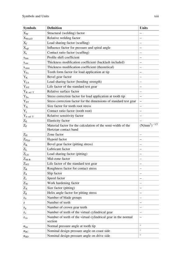
XW Structural (welding) factor –
XWrelT Relative welding factor –
XΓ Load sharing factor (scuffing) –
Xαβ Influence factor for pressure and spiral angle –
Xε Contact ratio factor (scuffing) –
xhm Profile shift coefficient –
xsm Thickness modification coefficient (backlash included) –
xsmn Thickness modification coefficient (theoretical) –
YFa Tooth form factor for load application at tip –
YK Bevel gear factor –
YLS Load sharing factor (bending strength) –
YNT Life factor of the standard test gear –
YR rel T Relative surface factor –
YSa Stress correction factor for load application at tooth tip –
YST Stress correction factor for the dimensions of standard test gear –
YX Size factor for tooth root stress –
Yε Contact ratio factor (tooth root) –
Yσ rel T Relative sensitivity factor –
ZE Elasticity factor –
ZF Material factor for the calculation of the semi-width of the
Hertzian contact band
(N/mm2)�1/3
ZH Zone factor –
ZHyp Hypoid factor –
ZK Bevel gear factor (pitting stress) –
ZL Lubricant factor –
ZLS Load sharing factor (pitting) –
ZM-B Mid-zone factor –
ZNT Life factor of the standard test gear –
ZR Roughness factor for contact stress –
ZS Slip factor –
Zv Speed factor –
ZW Work hardening factor –
ZX Size factor (pitting) –
Zβ Helix angle factor for pitting stress –
z0 Number of blade groups –
z Number of teeth –
zp Number of crown gear teeth –
zv Number of teeth of the virtual cylindrical gear –
zvn Number of teeth of the virtual cylindrical gear in the normal
section
–
αan Normal pressure angle at tooth tip �
αdC Nominal design pressure angle on coast side �
αdD Nominal design pressure angle on drive side �
Symbols and Units xiii
Symbols Definition Units
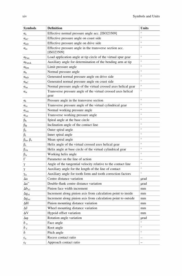
αe Effective normal pressure angle acc. [ISO23509] �
αeC Effective pressure angle on coast side �
αeD Effective pressure angle on drive side �
αet Effective pressure angle in the transverse section acc.
[ISO23509]
�
αFan Load application angle at tip circle of the virtual spur gear �
αFanΔ Auxiliary angle for determination of the bending arm at tip �
αlim Limit pressure angle �
αn Normal pressure angle �
αnD Generated normal pressure angle on drive side �
αnC Generated normal pressure angle on coast side �
αsn Normal pressure angle of the virtual crossed axes helical gear �
αst Transverse pressure angle of the virtual crossed axes helical
gear
�
αt Pressure angle in the transverse section �
αvt Transverse pressure angle of the virtual cylindrical gear �
αwn Normal working pressure angle �
αwt Transverse working pressure angle �
βb Spiral angle at the base circle �
βB Inclination angle of the contact line �
βe Outer spiral angle �
βi Inner spiral angle �
βm, βv Mean spiral angle �
βs Helix angle of the virtual crossed axes helical gear �
βvb Helix angle at base circle of the virtual cylindrical gear �
βw Working helix angle �
Γ Parameter on the line of action –
γ Angle of the tangential velocity relative to the contact line �
γ Auxiliary angle for the length of the line of contact �
γα Auxiliary angle for tooth form and tooth correction factors �
Δa Centre distance variation μradΔa” Double-flank centre distance variation μradΔbx1 Pinion face width increment mm
Δgxi Increment along pinion axis from calculation point to inside mm
Δgxe Increment along pinion axis from calculation point to outside mm
ΔH Pinion mounting distance variation mm
ΔJ Wheel mounting distance variation mm
ΔV Hypoid offset variation mm
Δφ Rotation angle variation μradδ a Face angle �
δ f Root angle �
δ Pitch angle �
εa Recess contact ratio –
εf Approach contact ratio –
xiv Symbols and Units
Symbols Definition Units
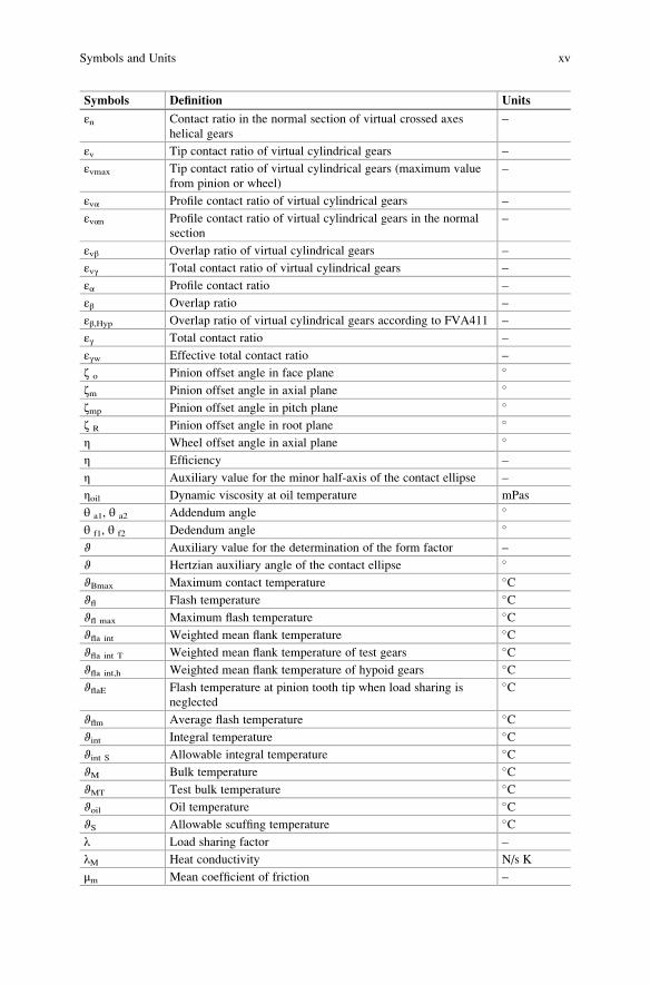
εn Contact ratio in the normal section of virtual crossed axes
helical gears
–
εv Tip contact ratio of virtual cylindrical gears –
εvmax Tip contact ratio of virtual cylindrical gears (maximum value
from pinion or wheel)
–
εvα Profile contact ratio of virtual cylindrical gears –
εvαn Profile contact ratio of virtual cylindrical gears in the normal
section
–
εvβ Overlap ratio of virtual cylindrical gears –
εvγ Total contact ratio of virtual cylindrical gears –
εα Profile contact ratio –
εβ Overlap ratio –
εβ,Hyp Overlap ratio of virtual cylindrical gears according to FVA411 –
εγ Total contact ratio –
εγw Effective total contact ratio –
ζ o Pinion offset angle in face plane �
ζm Pinion offset angle in axial plane �
ζmp Pinion offset angle in pitch plane �
ζ R Pinion offset angle in root plane �
η Wheel offset angle in axial plane �
η Efficiency –
η Auxiliary value for the minor half-axis of the contact ellipse –
ηoil Dynamic viscosity at oil temperature mPas
θ a1, θ a2 Addendum angle �
θ f1, θ f2 Dedendum angle �
ϑ Auxiliary value for the determination of the form factor –
ϑ Hertzian auxiliary angle of the contact ellipse �
ϑBmax Maximum contact temperature �Cϑfl Flash temperature �Cϑfl max Maximum flash temperature �Cϑfla int Weighted mean flank temperature �Cϑfla int T Weighted mean flank temperature of test gears �Cϑfla int,h Weighted mean flank temperature of hypoid gears �CϑflaE Flash temperature at pinion tooth tip when load sharing is
neglected
�C
ϑflm Average flash temperature �Cϑint Integral temperature �Cϑint S Allowable integral temperature �CϑM Bulk temperature �CϑMT Test bulk temperature �Cϑoil Oil temperature �CϑS Allowable scuffing temperature �Cλ Load sharing factor –
λM Heat conductivity N/s K
μm Mean coefficient of friction –
Symbols and Units xv

Symbols Definition Units
μmC Mean coefficient of friction at pitch point –
μmZ Mean coefficient of friction according to Wech –
υ Poisson’s ratio –
ν Lead angle of cutter �
ξ Contact ellipse semi-minor axis auxiliary value –
ρ Curvature radius mm
ρa0 Tool edge radius mm
ρb Epicycloid base circle radius mm
ρC Equivalent curvature radius at pitch point mm
ρCn Equivalent curvature radius at pitch point in the normal plane mm
ρE Curvature radius at pinion tip mm
ρers Equivalent curvature radius mm
ρF Fillet radius at point of contact of 30� tangent mm
ρlim Limit curvature radius mm
ρM Density kg/mm3
ρn Curvature radius in normal section mm
ρP0 Crown gear to cutter centre distance mm
ρred Relative radius of curvature mm
ρYn Curvature radius at contact point Y in normal plane mm
σF Tooth root stress N/mm2
σF lim Nominal stress number (bending) N/mm2
σF0 Local tooth root stress N/mm2
σFE Allowable stress number (bending) N/mm2
σFP Permissible tooth root stress N/mm2
σH Contact stress N/mm2
σH lim Allowable stress number for contact stress N/mm2
σH0 Nominal value of contact stress N/mm2
σHP Permissible contact stress N/mm2
Σ Shaft angle �
Σθ f Sum of dedendum angles �
Σθ fC Sum of dedendum angles for constant slot width taper �
Σθ fS Sum of dedendum angles for standard taper �
Σθ fM Sum of dedendum angles for modified slot width taper �
Σθ fU Sum of dedendum angles for uniform depth taper �
φ Angle between two contact lines �
φ Rotation angle μradω Angular speed, angular frequency 1/s
xvi Symbols and Units

Typical Indices
Index Definition
A, B, D, E Characteristic points on path of contact
a Tooth tip
b Base circle
C Coast side
C, S, M Pitch point, helix point, mean point
D Drive side
e Outer cone (heel) or “effective”
f Tooth root
i Inner cone (toe)
m Mean cone
n Normal section
P Reference profile or basic crown gear
s Virtual crossed axes helical gear
t Transverse section
v Virtual cylindrical gear
x Any point
Y Any point on the path of contact
y Any point
0 Generating tool
1 Pinion
2 Wheel
Typical Abbreviations
Abbreviation Definition
A Starting point of path of contact
B Inner point of single-flank mesh
C Pitch point
D Outer point of single-flank mesh
E End of path of contact
EWP Single-flank test
FH Face hobbing (continuous indexing)
FM Face milling (single indexing)
KS Structure-borne noise
KSP Structure-borne noise test
ZWP Double-flank test
2F Two-face grinding
3F Three-face grinding
Symbols and Units xvii

ThiS is a FM Blank Page

The original version of this book was revised. An erratum to this book can be found
at DOI 10.1007/978-3-662-43893-0_9.

ThiS is a FM Blank Page
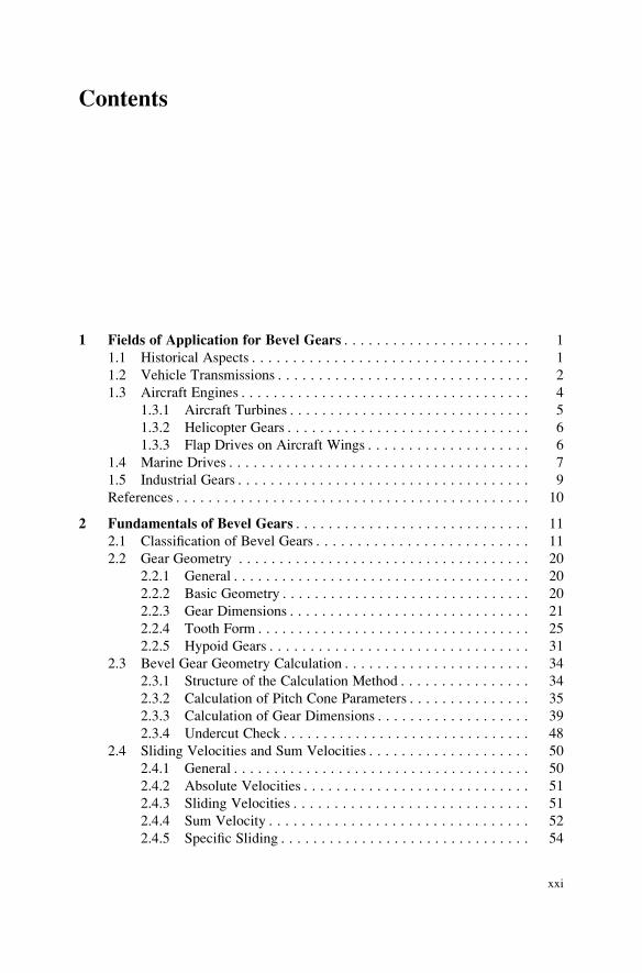
Contents
1 Fields of Application for Bevel Gears . . . . . . . . . . . . . . . . . . . . . . . 1
1.1 Historical Aspects . . . . . . . . . . . . . . . . . . . . . . . . . . . . . . . . . . 1
1.2 Vehicle Transmissions . . . . . . . . . . . . . . . . . . . . . . . . . . . . . . . 2
1.3 Aircraft Engines . . . . . . . . . . . . . . . . . . . . . . . . . . . . . . . . . . . . 4
1.3.1 Aircraft Turbines . . . . . . . . . . . . . . . . . . . . . . . . . . . . . . 5
1.3.2 Helicopter Gears . . . . . . . . . . . . . . . . . . . . . . . . . . . . . . 6
1.3.3 Flap Drives on Aircraft Wings . . . . . . . . . . . . . . . . . . . . 6
1.4 Marine Drives . . . . . . . . . . . . . . . . . . . . . . . . . . . . . . . . . . . . . 7
1.5 Industrial Gears . . . . . . . . . . . . . . . . . . . . . . . . . . . . . . . . . . . . 9
References . . . . . . . . . . . . . . . . . . . . . . . . . . . . . . . . . . . . . . . . . . . . 10
2 Fundamentals of Bevel Gears . . . . . . . . . . . . . . . . . . . . . . . . . . . . . 11
2.1 Classification of Bevel Gears . . . . . . . . . . . . . . . . . . . . . . . . . . 11
2.2 Gear Geometry . . . . . . . . . . . . . . . . . . . . . . . . . . . . . . . . . . . . 20
2.2.1 General . . . . . . . . . . . . . . . . . . . . . . . . . . . . . . . . . . . . . 20
2.2.2 Basic Geometry . . . . . . . . . . . . . . . . . . . . . . . . . . . . . . . 20
2.2.3 Gear Dimensions . . . . . . . . . . . . . . . . . . . . . . . . . . . . . . 21
2.2.4 Tooth Form . . . . . . . . . . . . . . . . . . . . . . . . . . . . . . . . . . 25
2.2.5 Hypoid Gears . . . . . . . . . . . . . . . . . . . . . . . . . . . . . . . . 31
2.3 Bevel Gear Geometry Calculation . . . . . . . . . . . . . . . . . . . . . . . 34
2.3.1 Structure of the Calculation Method . . . . . . . . . . . . . . . . 34
2.3.2 Calculation of Pitch Cone Parameters . . . . . . . . . . . . . . . 35
2.3.3 Calculation of Gear Dimensions . . . . . . . . . . . . . . . . . . . 39
2.3.4 Undercut Check . . . . . . . . . . . . . . . . . . . . . . . . . . . . . . . 48
2.4 Sliding Velocities and Sum Velocities . . . . . . . . . . . . . . . . . . . . 50
2.4.1 General . . . . . . . . . . . . . . . . . . . . . . . . . . . . . . . . . . . . . 50
2.4.2 Absolute Velocities . . . . . . . . . . . . . . . . . . . . . . . . . . . . 51
2.4.3 Sliding Velocities . . . . . . . . . . . . . . . . . . . . . . . . . . . . . 51
2.4.4 Sum Velocity . . . . . . . . . . . . . . . . . . . . . . . . . . . . . . . . 52
2.4.5 Specific Sliding . . . . . . . . . . . . . . . . . . . . . . . . . . . . . . . 54
xxi
2.5 Tooth Forces . . . . . . . . . . . . . . . . . . . . . . . . . . . . . . . . . . . . . . 54
2.5.1 Tooth Force Analysis . . . . . . . . . . . . . . . . . . . . . . . . . . . 54
2.5.2 Calculation of Tooth Forces . . . . . . . . . . . . . . . . . . . . . . 55
2.5.3 Bearing Forces . . . . . . . . . . . . . . . . . . . . . . . . . . . . . . . 56
References . . . . . . . . . . . . . . . . . . . . . . . . . . . . . . . . . . . . . . . . . . . . 56
3 Design . . . . . . . . . . . . . . . . . . . . . . . . . . . . . . . . . . . . . . . . . . . . . . . 57
3.1 Starting Values for the Geometry . . . . . . . . . . . . . . . . . . . . . . . 57
3.2 Manufacturing Kinematics . . . . . . . . . . . . . . . . . . . . . . . . . . . . 65
3.2.1 Basic Rack and Virtual Crown Gear (Generating Gear) . . . 65
3.2.2 Model of a Virtual Bevel Gear Machine . . . . . . . . . . . . . 67
3.2.3 Calculation Model . . . . . . . . . . . . . . . . . . . . . . . . . . . . . 69
3.2.4 Sample Calculation of Machine Kinematics . . . . . . . . . . 70
3.3 Tooth Contact Analysis . . . . . . . . . . . . . . . . . . . . . . . . . . . . . . . 72
3.3.1 Tooth Geometry Calculation . . . . . . . . . . . . . . . . . . . . . 72
3.3.2 Crowning . . . . . . . . . . . . . . . . . . . . . . . . . . . . . . . . . . . 73
3.3.3 Ease-off, Contact Pattern and Transmission Error . . . . . . 75
3.3.4 Additional Motions . . . . . . . . . . . . . . . . . . . . . . . . . . . . 78
3.4 Displacement Behavior . . . . . . . . . . . . . . . . . . . . . . . . . . . . . . . 80
3.4.1 Horizontal and Vertical Displacements . . . . . . . . . . . . . . 80
3.4.2 Displacements Caused by Tooth Forces . . . . . . . . . . . . . 81
3.4.3 Contact Pattern Displacement . . . . . . . . . . . . . . . . . . . . . 83
3.4.4 Influence of the Tool Radius . . . . . . . . . . . . . . . . . . . . . 85
3.4.5 Ease-Off Design . . . . . . . . . . . . . . . . . . . . . . . . . . . . . . 87
3.5 Material Specification . . . . . . . . . . . . . . . . . . . . . . . . . . . . . . . . 90
3.5.1 Introduction . . . . . . . . . . . . . . . . . . . . . . . . . . . . . . . . . 90
3.5.2 Materials for Bevel Gears . . . . . . . . . . . . . . . . . . . . . . . 91
3.5.3 Case Hardening Steels . . . . . . . . . . . . . . . . . . . . . . . . . . 92
3.6 Choice of Lubricant . . . . . . . . . . . . . . . . . . . . . . . . . . . . . . . . . 95
3.6.1 Introduction . . . . . . . . . . . . . . . . . . . . . . . . . . . . . . . . . 95
3.6.2 Selection of the Lubricant . . . . . . . . . . . . . . . . . . . . . . . 95
3.6.3 Choice of Oil Type . . . . . . . . . . . . . . . . . . . . . . . . . . . . 96
3.6.4 Choice of Oil Properties . . . . . . . . . . . . . . . . . . . . . . . . . 96
3.6.5 Oil Feed . . . . . . . . . . . . . . . . . . . . . . . . . . . . . . . . . . . . 98
3.6.6 Oil Monitoring . . . . . . . . . . . . . . . . . . . . . . . . . . . . . . . 99
References . . . . . . . . . . . . . . . . . . . . . . . . . . . . . . . . . . . . . . . . . . . . 99
4 Load Capacity and Efficiency . . . . . . . . . . . . . . . . . . . . . . . . . . . . . 101
4.1 Gear Failure Modes . . . . . . . . . . . . . . . . . . . . . . . . . . . . . . . . . 101
4.1.1 Classification of Failure Modes . . . . . . . . . . . . . . . . . . . 101
4.1.2 Tooth Root Breakage . . . . . . . . . . . . . . . . . . . . . . . . . . . 103
4.1.3 Flank Breakage . . . . . . . . . . . . . . . . . . . . . . . . . . . . . . . 104
4.1.4 Pitting . . . . . . . . . . . . . . . . . . . . . . . . . . . . . . . . . . . . . . 105
4.1.5 Micropitting . . . . . . . . . . . . . . . . . . . . . . . . . . . . . . . . . 106
4.1.6 Wear . . . . . . . . . . . . . . . . . . . . . . . . . . . . . . . . . . . . . . . 107
xxii Contents
4.1.7 Ridging and Rippling . . . . . . . . . . . . . . . . . . . . . . . . . . . 108
4.1.8 Scuffing . . . . . . . . . . . . . . . . . . . . . . . . . . . . . . . . . . . . 109
4.2 Load Capacity Calculation . . . . . . . . . . . . . . . . . . . . . . . . . . . . 111
4.2.1 Standards and Calculation Methods . . . . . . . . . . . . . . . . 111
4.2.2 Virtual Cylindrical Gears for Tooth Root and Pitting
Load Capacity . . . . . . . . . . . . . . . . . . . . . . . . . . . . . . . . 112
4.2.3 Virtual Cylindrical Gears for Scuffing Load Capacity . . . 117
4.2.4 Tooth Root Load Capacity . . . . . . . . . . . . . . . . . . . . . . . 120
4.2.5 Pitting Load Capacity . . . . . . . . . . . . . . . . . . . . . . . . . . 132
4.2.6 Scuffing Load Capacity . . . . . . . . . . . . . . . . . . . . . . . . . 140
4.2.7 Calculation of the Load Capacity for a Load Spectrum . . . 156
4.3 Efficiency . . . . . . . . . . . . . . . . . . . . . . . . . . . . . . . . . . . . . . . . 157
4.3.1 Total Power Loss of a Gear Unit . . . . . . . . . . . . . . . . . . 157
4.3.2 Influences on Gear Efficiency . . . . . . . . . . . . . . . . . . . . . 158
4.3.3 Calculation of Gear Efficiency . . . . . . . . . . . . . . . . . . . . 160
4.4 Stress Analysis . . . . . . . . . . . . . . . . . . . . . . . . . . . . . . . . . . . . . 165
4.4.1 Preliminary Considerations . . . . . . . . . . . . . . . . . . . . . . 165
4.4.2 Methods for the Determination of Tooth Meshing
Stresses . . . . . . . . . . . . . . . . . . . . . . . . . . . . . . . . . . . . . 165
4.4.3 Special Methods of Stress Analysis . . . . . . . . . . . . . . . . 170
References . . . . . . . . . . . . . . . . . . . . . . . . . . . . . . . . . . . . . . . . . . . . 192
5 Noise Behavior . . . . . . . . . . . . . . . . . . . . . . . . . . . . . . . . . . . . . . . . 197
5.1 Causes of Noise Generation . . . . . . . . . . . . . . . . . . . . . . . . . . . 197
5.2 Noise Excitation by Means of Gear Tooth Design . . . . . . . . . . . 200
5.2.1 Optimizing the Macro Geometry . . . . . . . . . . . . . . . . . . 200
5.2.2 Optimizing the Micro Geometry . . . . . . . . . . . . . . . . . . . 208
5.2.3 Influence of Gear Crowning . . . . . . . . . . . . . . . . . . . . . . 209
5.3 Noise Excitation Governed by Manufacturing . . . . . . . . . . . . . . 211
5.3.1 Influence of Gear Deviations on Transmission Error . . . . 211
5.3.2 Manufacturing Process Influence on the Transmission
Error . . . . . . . . . . . . . . . . . . . . . . . . . . . . . . . . . . . . . . . 217
5.4 Dynamic Noise Excitation . . . . . . . . . . . . . . . . . . . . . . . . . . . . 223
5.4.1 Dynamic of Bevel Gear Running Behavior . . . . . . . . . . . 223
5.4.2 Calculating Load-Free and Load-Dependent Running
Behavior . . . . . . . . . . . . . . . . . . . . . . . . . . . . . . . . . . . . 224
5.4.3 Test Rig for Rear Axle Gears . . . . . . . . . . . . . . . . . . . . . 226
5.4.4 Test Results . . . . . . . . . . . . . . . . . . . . . . . . . . . . . . . . . 227
References . . . . . . . . . . . . . . . . . . . . . . . . . . . . . . . . . . . . . . . . . . . . 230
6 Manufacturing Process . . . . . . . . . . . . . . . . . . . . . . . . . . . . . . . . . . 233
6.1 Introduction . . . . . . . . . . . . . . . . . . . . . . . . . . . . . . . . . . . . . . . 233
6.2 Cutting of Spiral Bevel Gears . . . . . . . . . . . . . . . . . . . . . . . . . . 235
6.2.1 Development History . . . . . . . . . . . . . . . . . . . . . . . . . . . 235
6.2.2 Development Trends . . . . . . . . . . . . . . . . . . . . . . . . . . . 236
6.2.3 Tools . . . . . . . . . . . . . . . . . . . . . . . . . . . . . . . . . . . . . . 236
Contents xxiii

6.2.4 Blade Materials . . . . . . . . . . . . . . . . . . . . . . . . . . . . . . . 251
6.2.5 Manufacturing Technology . . . . . . . . . . . . . . . . . . . . . . 251
6.3 Heat Treatment . . . . . . . . . . . . . . . . . . . . . . . . . . . . . . . . . . . . 257
6.3.1 Fundamentals of Hardening . . . . . . . . . . . . . . . . . . . . . . 257
6.3.2 Heat Treatment Processes . . . . . . . . . . . . . . . . . . . . . . . 258
6.3.3 Thermal Processes . . . . . . . . . . . . . . . . . . . . . . . . . . . . . 258
6.3.4 Thermo-chemical Processes . . . . . . . . . . . . . . . . . . . . . . 259
6.3.5 Temperature Profiles in Case Hardening . . . . . . . . . . . . . 263
6.3.6 Hardening Distortions . . . . . . . . . . . . . . . . . . . . . . . . . . 264
6.3.7 Fixture Hardening . . . . . . . . . . . . . . . . . . . . . . . . . . . . . 267
6.4 Hard Skiving . . . . . . . . . . . . . . . . . . . . . . . . . . . . . . . . . . . . . . 268
6.5 Grinding Spiral Bevel Gears . . . . . . . . . . . . . . . . . . . . . . . . . . . 269
6.5.1 Development History . . . . . . . . . . . . . . . . . . . . . . . . . . . 269
6.5.2 Development Trends . . . . . . . . . . . . . . . . . . . . . . . . . . . 270
6.5.3 Tools . . . . . . . . . . . . . . . . . . . . . . . . . . . . . . . . . . . . . . 270
6.5.4 Abrasives . . . . . . . . . . . . . . . . . . . . . . . . . . . . . . . . . . . 272
6.5.5 Grinding Technology . . . . . . . . . . . . . . . . . . . . . . . . . . . 275
6.6 Lapping . . . . . . . . . . . . . . . . . . . . . . . . . . . . . . . . . . . . . . . . . . 285
6.6.1 Development History . . . . . . . . . . . . . . . . . . . . . . . . . . . 285
6.6.2 Description of the Process . . . . . . . . . . . . . . . . . . . . . . . 285
6.6.3 Lapping Media . . . . . . . . . . . . . . . . . . . . . . . . . . . . . . . 286
6.6.4 Process Parameters . . . . . . . . . . . . . . . . . . . . . . . . . . . . 287
6.6.5 Using Lapping to Change Running Properties . . . . . . . . . 289
References . . . . . . . . . . . . . . . . . . . . . . . . . . . . . . . . . . . . . . . . . . . . 290
7 Quality Assurance . . . . . . . . . . . . . . . . . . . . . . . . . . . . . . . . . . . . . . 291
7.1 Measurement and Correction . . . . . . . . . . . . . . . . . . . . . . . . . . . 291
7.1.1 Measuring Tasks . . . . . . . . . . . . . . . . . . . . . . . . . . . . . . 291
7.1.2 Pitch Measurement . . . . . . . . . . . . . . . . . . . . . . . . . . . . 292
7.1.3 Flank Form Measurements . . . . . . . . . . . . . . . . . . . . . . . 294
7.1.4 Additional Measuring Tasks . . . . . . . . . . . . . . . . . . . . . . 297
7.1.5 Closed Loop Production . . . . . . . . . . . . . . . . . . . . . . . . . 299
7.2 Testing Bevel Gear Sets . . . . . . . . . . . . . . . . . . . . . . . . . . . . . . 303
7.2.1 Fundamentals . . . . . . . . . . . . . . . . . . . . . . . . . . . . . . . . 303
7.2.2 Contact Pattern Test . . . . . . . . . . . . . . . . . . . . . . . . . . . 304
7.2.3 Single-Flank Test . . . . . . . . . . . . . . . . . . . . . . . . . . . . . 304
7.2.4 Double-Flank Test . . . . . . . . . . . . . . . . . . . . . . . . . . . . . 307
7.2.5 Structure-Borne Noise Test . . . . . . . . . . . . . . . . . . . . . . 308
7.2.6 Comparison of Rolling Test Methods . . . . . . . . . . . . . . . 309
References . . . . . . . . . . . . . . . . . . . . . . . . . . . . . . . . . . . . . . . . . . . . 310
8 Dynamics of Machine Tools . . . . . . . . . . . . . . . . . . . . . . . . . . . . . . 311
8.1 Introduction . . . . . . . . . . . . . . . . . . . . . . . . . . . . . . . . . . . . . . . 311
8.2 Static Machine Behavior . . . . . . . . . . . . . . . . . . . . . . . . . . . . . . 312
xxiv Contents

8.3 Dynamic Machine Behavior . . . . . . . . . . . . . . . . . . . . . . . . . . . 313
8.3.1 Simulation Methods . . . . . . . . . . . . . . . . . . . . . . . . . . . . 313
8.3.2 Modal Analysis . . . . . . . . . . . . . . . . . . . . . . . . . . . . . . . 318
References . . . . . . . . . . . . . . . . . . . . . . . . . . . . . . . . . . . . . . . . . . . . 319
Erratum to: Bevel Gear . . . . . . . . . . . . . . . . . . . . . . . . . . . . . . . . . . . . . E1
Trademarks . . . . . . . . . . . . . . . . . . . . . . . . . . . . . . . . . . . . . . . . . . . . . . 321
Index . . . . . . . . . . . . . . . . . . . . . . . . . . . . . . . . . . . . . . . . . . . . . . . . . . . 323
Contents xxv

ThiS is a FM Blank Page

List of Contributors
Christian Brecher Professor Dr.-Ing., Lehrstuhl fur Werkzeugmaschinen, RWTH
Aachen
Markus Brumm Dr.-Ing., Klingelnberg GmbH, Huckeswagen
Uwe Epler Dipl.-Ing., Klingelnberg GmbH, Huckeswagen
Adam Gacka Dr.-Ing., Caterpillar Global Mining Europe GmbH, Lunen, Germany
Bernd-Robert Hohn Professor Dr.-Ing., Lehrstuhl fur Maschinenelemente, TU
Munchen
Carsten Hunecke Dr.-Ing., Klingelnberg GmbH, Huckeswagen
Roger Kirsch Dipl.-Ing., Reishauer AG, Wallisellen
Markus Klein Dr.-Ing., Airbus Helicopters, Donauworth
Alexander Landvogt Dr.-Ing., Klingelnberg GmbH, Ettlingen
Klaus Michaelis Dr.-Ing., Lehrstuhl fur Maschinenelemente, TU Munchen
Hartmuth Muller Dr.-Ing., Klingelnberg GmbH, Huckeswagen
Karl-Martin Ribbeck Dipl.-Ing., Klingelnberg GmbH, Huckeswagen
Berthold Schlecht Professor Dr.-Ing., Institut fur Maschinenelemente und
Maschinenkonstruktion, TU Dresden
Frank Seibicke Dipl.-Ing., Klingelnberg GmbH, Ettlingen
Michael Senf Dr.-Ing., Institut fur Maschinenelemente und Maschinenkon-
struktion, TU Dresden
Joachim Thomas Dr. Ing., ZG Hypoid GmbH, Eching-Dietersheim
xxvii

Hans-Jurgen Trapp Dr.-Ing., Klingelnberg GmbH, Huckeswagen
Olaf Vogel Dr. rer. nat., Klingelnberg GmbH, Ettlingen
Christian Wirth Dr.-Ing., ZG GmbH, Eching-Dietersheim
xxviii List of Contributors