betonbau in der schweiz layout 1 - feb.sia.ch concrete in... · betonbau in der schweiz...
TRANSCRIPT

Betonbau in der SchweizConstruction en béton en SuisseStructural Concrete in Switzerland
The forth fib-CongressFebruary 10 to 14, 2014, Mumbai, India
fib-CH Betontag/Journée du béton 2014
Schweizer Gruppe der internationalen Vereinigung für BetonGroupe national suisse de la féderation internationale du bétonSwiss national group of the international federation for structural concrete

Redaktoren-TeamHans Rudolf Ganz (Leitung), Dr. sc. techn., dipl. Bauing. ETH, BösingenWalter Kaufmann, Dr. sc. techn., dipl. Bauing. ETH, GreifenseeJean-François Klein, Dr ès sc. techn., ing. dipl. EPF, GenèveMario Monotti, Prof. Dr. sc. techn., dipl. Bauing. ETH, LocarnoAurelio Muttoni, Prof. Dr. sc. techn., dipl. Bauing. ETH, LausanneFrançois Prongué, ing. dipl. EPF, MoudonTomaz Ulaga, Dr. sc. techn., dipl. Bauing. ETH, BaselHeiner Widmer, Dr. phil. nat., Bern
Lektorat englische TexteEdward G. Prater, Bubikon
Gestaltung und ProduktionMartin Grether, Techkomm, Zürich
DruckStämpfli Publikationen AG, Bern
Fotos UmschlagSporthallen Mülimatt, Brugg (© Kanton Aargau, Foto: René Rötheli,Baden); Pont de la Poya, Fribourg; Betonschale, Chiasso; Viaduc sur leRhône (© Yves André)
© Copyright 2014 by fib-CH
fib-CHp/a EPFL ENAC IBETONBâtiment GC B2Station 18CH-1015 Lausanne
Alle Rechte, auch das des auszugsweisen Nachdrucks, der auszugs -weisen oder vollständigen Wiedergabe (Fotokopie, Mikrokopie, CD-ROM usw.), der Speicherung in Datenverarbeitungsanlagen und das der Übersetzung, sind vorbehalten.
ISBN 978-2-8399-1343-0Auflage: 4000 Exemplare

Betonbau in der SchweizConstruction en béton en SuisseStructural Concrete in Switzerland
The forth fib-CongressFebruary 10 to 14, 2014, Mumbai, India
fib-CH Betontag/Journée du béton 2014
Schweizer Gruppe der internationalen Vereinigung für BetonGroupe national suisse de la féderation internationale du bétonSwiss national group of the international federation for structural concrete

Vorwort
Die fédération internationale du béton fib ist diegrösste internationale Vereinigung, die sich mit demBetonbau befasst. Die fib hat gemäss ihren Statutenfolgende Hauptziele: • Fördern von Forschung auf dem Gebiet der Be ton -
bauweise;• Zusammenfassen von Ergebnissen aus Forschung
und Praxis; • Verbreiten der Ergebnisse mit Publikationen und
Empfehlungen sowie internationalen Kongres -sen, Symposien und Workshops;
• Erarbeiten von international gültigen Empfeh lun -gen für die Bemessung und den Bau von Beton -bauten;
• Informieren der Mitglieder über die neuestenEnt wicklungen im Betonbau.
Die fib wird heute von 42 nationalen Delegationenaus allen 5 Kontinenten getragen und hat ein per-manentes Sekretariat an der ETH Lausanne (www.fib-international.org). Zehn Kommissionen und eine grosse Anzahl vonspeziellen Arbeitsgruppen bearbeiten Teilgebieteder Betonbauweise. Die Resultate werden regelmäs-sig in fib-Bulletins oder in speziellen Publikationenpubliziert.Die Schweizer Delegation – die fib-CH – beschloss,anlässlich des fib-Kongresses in Mumbai 2014 wie-der einen Querschnitt durch herausragende Leis -tungen im schweizerischen Betonbau in einer spe-ziellen Publikation darzustellen. Die Publikation der fib-CH soll einerseits die interna-tionale Fachwelt auf Leistungen und Innovationenim Schweizer Bauwesen aufmerksam machen undandererseits Schweizer Baufachleute auf breiterBasis über die in den vergangenen vier Jahren er -brach ten Spitzenleistungen auf dem Gebiet derBeton bauweise informieren. Im Nachgang an den internationalen fib-Kongress inMumbai 2014 werden ausgewählte Beiträge der Pub -likation im Rahmen des Betontages 2014 der fib-CHeinem breiten schweizerischen Publi kum vorgestelltwerden. Die Finanzierung der Publikation der fib-CH war nurdank der grossen Unterstützung der am Schluss derPublikation aufgeführten Sponsoren möglich. Wirdanken den Geldgebern ganz herzlich.
Ein spezieller Dank gebührt auch den Autoren. Erstihre Beiträge ermöglichten die Publikation.
Februar 2014
Redaktoren-Team der fib-CH
Alle Beiträge stehen als PDF zur Verfügung:
http://fib-ch.epfl.ch/pubs
6
Forschung und EntwicklungRecherche et développementResearch and development 10
René Suter, João Tomás, Lionel MoreillonComportement structural de poutres ajourées en béton fibré à hautes performancesStructural behaviour of cellular beams in high performance concrete 12
Hartwig Stempfle, Edith SchurtenbergerTextilbetonplattenversuchePlate tests on textile-reinforced concrete 18
Pietro Lura, Andreas Leemann, Carmelo Di BellaDer Einfluss der Betonzusammensetzung auf das Risiko der Bildung plastischer SchwindrisseThe influence of concrete composition on the risk of plastic shrinkage cracking 24
Thomas Vogel, Patrick FehlmannVersuche und physikalisches Berechnungsmodell zur Ermüdung von StahlbetonbrückenTests on and physical calculation model for fatigue in reinforced concrete bridges 29
Julien Michels, Christoph Czaderski, Masoud MotavalliGradientenverankerung für vorgespannte CFK-Lamellen im BetonbauGradient anchorage for prestressed CFRP strips bonded to concrete 35
HochbauBâtimentBuildings 40
Massimo Laffranchi, Armand FürstDie Sporthallen Mülimatt in BruggSports hall Mülimatt, Brugg 42
Aurelio MuttoniUne nouvelle toiture pour le Musée Olympique à LausanneA new roof for the Olympic Museum at Lausanne 48
Inhalt · Table des matières · Content

7
Henri Brasey, François Prongué, Jean-François KleinLa salle de spectacle «Equilibre» à FribourgThe new ”Equilibre” theatre in Fribourg 54
Philippe Menétrey, Jonathan KrebsManufacture Cartier Horlogerie à CouvetCartier Horlogerie factory at Couvet 58
Joseph SchwartzErweiterungsbau Kongresszentrum DavosExtension of the Davos Convention Centre 64
Patrick GartmannSchulhaus Grono – Kraft und FormGrono School – Force and Form 69
Aurelio Muttoni, Miguel Fernández RuizCanopée en béton armé à la «Maison de l’Écriture» à MontricherConcrete Canopy of ”Maison de l’Ecriture” in Montricher 75
Aurelio Muttoni, Franco Lurati, Miguel Fernández RuizConstruction d’une coque en béton armé à ChiassoConstruction of an ellipsoidal concrete shell in Chiasso 80
Andrea Pedrazzini, Eugenio Pedrazzini, Roberto GuidottiPalestra doppia a ChiassoDouble gymnasium in Chiasso 84
Mario MonottiAbitazione sul lago di SarnenHouse on Lake Sarnen 89
Fabian PerschElefantenpark «Kaeng Krachang» im Zoo Zürich – BetontragwerkElephant House ”Kaeng Krachang” in the Zurich Zoo – Concrete structure 93

8
BrückenPontsBridges 98
Bernard Houriet, Pierre Gorgé, Sylvain Plumey, Aldo Bisetti, Jean-François GnaegiLe Pont de la PoyaThe Poya bridge 100
Walter KaufmannErsatz Steinbachviadukt – neue Brücke über den SihlseeReplacement of Steinbach Viaduct – new bridge over the Sihlsee Reservoir 107
Beat Meier, Oliver Müller Neubau VersamertobelbrückeNew Versam Gorge Bridge 113
Philippe Menétrey, Claude Broquet, Stefan NydeggerViaduc sur l’A9Viaduct on the A9 118
Ramon Pinol, Philippe Meier, Ana-Inès PepermansViaduc sur le RhôneViaduct over the Rhone 124
IngenieurbauGénie civilCivil engineering 130
Martin O. Bachmann, Valentin RabitschTiefbahnhof Löwenstrasse der Zürcher DurchmesserlinieLöwenstrasse underground station on the Zurich Cross-City Line 132
Fabian Persch, Roland SchmedHauptbahnhof Zürich – Unterquerung SüdtraktZurich main station – undercrossing of the southern wing 141
Wolfram KüblerNeue Treppenaufgänge auf die Hardbrücke in ZürichNew staircases at Hardbrücke in Zurich 146
9
BauwerkserhaltungConservation des ouvragesConservation of structures 152
Jakob KunzVerstärkung mit nachträglich eingemörtelter Querkraftbewehrung Strengthening with post-installed shear reinforcement 154
Jürg WeberN1/312 Aabachtalviadukt, LenzburgN1/312 Aabachtal viaduct, Lenzburg 159
Dieter Flückiger, Ueli ReberInstandsetzung der HardbrückeRehabilitation of the Hardbrücke 165
Stefan Lips, Robert Koppitz, Albin Kenel, Thomas KellerNeue vorgespannte Durchstanzverstärkungssysteme für FlachdeckenNew prestressed punching strengthening systems for flat slabs 171
Tomaz Ulaga, Domink WeissUmbau und Instandsetzung der Markthalle BaselTransformation and repair of the Basel market hall 176
Karl BaumannNormalbauweise für Schottertröge auf MauerwerksviaduktenStandard ballast troughs on masonry viaducts 181
SponsorenSponsorsSponsors 186

Forschung und Entwicklung
Recherche et développement
Research and development

12
IntroductionDans le cadre d’un important pro-gramme de recherche sur les bé -tons fibrés à hautes perfor-mances, l’Ecole d’ingénieurs etd’architectes de Fribourg a procé-dé à des études théoriques etexpérimentales sur des poutresprécontraintes avec des ouvertu-res circulaires (Fig. 1). Ces poutresà ouvertures circulaires, nomméeségalement poutres ajourées, sontde plus en plus demandées par lesexigences de la pratique afin depermettre le passage de condui-tes techniques.Pour la construction en acier, despoutres ajourées sont réaliséesavec succès depuis des décennies.Pour la construction en béton, lesouvertures nécessitent des dispo-sitions d’armatures de cisaillementet de traction oblique compliquéeset difficiles à mettre en place (Fig.2). Il parait donc intéressant deremplacer cette armature de ci -saillement, partiellement ou tota-lement, par l’ajout de fibres mé -talliques. Dans certains cas, il seramême opportun de réaliser des
poutres en béton fibré ultra-per-formant.Pour analyser ce problème, deuxétudes expérimentales ont étéeffectuées. La première étude PUcomprenait cinq poutres en bétonfibré ultra-performant (BFUP) etla deuxième étude PH sept pou-tres en béton fibré à hautes per-formances (BFHP). L’objectif deces deux études était d’analyser lecomportement de poutres ajou-rées dans les états limites de ser-vice (ELS) et ultime (ELU).
Etude expérimentale PUDescription des essaisLes cinq poutres de la premièreétude expérimentale PU ont étéréalisés dans les usines de préfa-brication MFP SA à Cheyres dansun coffrage métallique qui avaitété conçu pour la fabrication despoutres de toiture recouvrant lenouveau Musée Olympique àLausanne (architecte: Brauen &Wälchli; ingénieur : Muttoni &Fernández). Le BFUP de type BSI(Béton Spécial industriel), déve-loppé par l’entreprise Eiffage SA
IntroductionAs part of an extensive researchprogram on high-performance fi -bre-reinforced concrete (HPFRC),the University of Applied Sciences(UAS) of Fribourg has carried outa theoretical and experimentalstudy on prestressed beams withcircular openings (Fig. 1). Such cir-cular openings are increasingly indemand due to practical require-ments of allowing the passage ofservice pipes.In steel construction cellular beamshave been used for decades.Regarding concrete beams, suchopenings require the provision ofboth shear and diagonal tensionreinforcement, which are compli-cated and difficult to implement(Fig. 2). Therefore, it is of interestto replace the shear reinforce-ment, partially or totally, by theaddition of fibres. Occasionally, itis even possible to make prestres-sed beams in ultra-high perfor-mance fibre-reinforced concrete.In order to analyse this problem,two experimental studies wereper formed. The first, PU, consist -
Comportement structural de poutres ajourées en béton fibréà hautes performancesStructural behaviour of cellular beams in high performanceconcrete
René Suter, João Tomás, Lionel Moreillon
Fig. 1
Poutres ajourées précontraintes.Prestressed beams with circular openings.
Fig. 2
Armature passive autour des ouvertures.Ordinary reinforcement around the openings.

13
présentait une résistance à lacompression sur cylindre fcm28 de180 MPa et un module d’élasticitéEcm28 de 58 GPa. Les poutres avaient une longueur de 9,00 m,une hauteur de 1000mm et uneépaisseur de 80/100 mm. L’ar ma -ture de flexion était composée dequatre torons précontraints de0,6”; trois de ces torons étaientplacés en inférieur et un toron ensupérieur. Les paramètres varia-bles étaient le diamètre desouvertures et le taux de précon-trainte. Les cinq poutres ont étésoumises à des essais de charge 4-points par l’application de deuxcharges concentrées et espacées
ed of five beams in ultra-high per -formance fiber-reinforced concre-te (UHPFRC) and the second, PH,consisted of seven beams in highperformance fibre-reinforced con -crete (HPFRC). The objective ofthese two studies was to analysethe behaviour of cellular beams inservice (SLS) and ultimate limitstates (ULS).
Experimental study PUDescription of the load testsThe five beams of the first experi-mental study PU were made atthe precast plant of MFP Pre -fabrication SA at Cheyres in a fra-mework which has been designed
for the roof elements of the newOlympic Museum in Lausanne (ar -chitect: Brauen & Wälchli; engi-neer: Muttoni & Fernández). TheUHPFRC of the type ISC (IndustrialSpecial Concrete), developed byEiffage SA, had a compressive cy -linder strength fcm28 of 180 MPaand a Young’s modulus Ecm28 of 58GPa. The beams had a length of9.00 m, a height of 1000 mm anda thickness of 80/100 mm. Thebending reinforcement con sis tedof three bottom prestressedstrands of 0.6” and one topstrand of 0.6”. The variable para-meters were the diameter of theopenings and the intensity of theprestressing. The five beams weresubjected to a 4-point load test byapplying two concentrated loads,which were spaced 3.00 m apart.Figure 3 shows the characteristicsof each beam tested and Figure 4illustrates beam’s geometry aswell as the experimental set-up.
Test resultsBeam PU1 exhibited a bendingfailure with concrete crushing inthe compressed zone (Fig. 5). Theelevated fibre dosage limited theformation of diagonal crackingand avoided a shear rupture (Fig.7a). For the beam PU2, a bendingfailure mechanism was also observ -ed (Fig. 7b). Thus, it may be statedthat ø=400 mm openings did notinfluence significantly the ultima-te shear strength. The failure loadof 625 kN was even superior tothe one of the reference beamPU1 (587 kN), due to more favou-rable fibre orientation in the rup-ture section.The two beams PU3 and PU4 exhi-bited shear failure mechanismscaused by shear and the presenceof openings (Fig. 8). The failureload was reduced to 519 kN and531 kN for beams PU 3 and PU 4,respectively. Thus, a 30% increasein the prestressing force led to a2% gain in the failure load, but a25% reduction on the mid-spandeflection. For the beam PU5,with ø=600 mm openings, a grea -ter decrease of the failure loadwas observed, reaching 418 kNwith a failure mechanism similarto that of a Vierendeel beam.
Fig. 4
Dispositif d’essai.Experimental set-up for UHPFRC beams.
SpecimenOpenings Prestressing force Fibre dosage
ø [mm] P0 [kN] [kg/m3]
PU1 – 4 x 125 240
PU2 400 4 x 125 240
PU3 500 4 x 125 240
PU4 500 4 x 175 240
PU5 600 4 x 125 240
Fig. 3
Caractéristiques des poutres, étude PU.Main properties of tested beams (UHPFRC).
SpecimenUltimate load Fu – Fu (Ref.)
FailureMid-span deflection
Fu [kN] Fu (Ref.) δu [mm]
PU1 (Ref.) 587 – Bending 62,3
PU2 625 +5% Bending 78,8
PU3 519 –16% Shear 59,0
PU4 531 –15% Shear 45,0
PU5 418 –30% Shear 44,7
Fig. 5
Charges et déplacements de ruine, étude PU.Experimental ultimate loads and associated mid-span displacements (UHPFRC).

14
de 3,00 m. La Figure 3 donne lescaractéristiques des différents élé-ments d’essai ; la Figure 4 illus trela géométrie des poutres ainsique le dispositif d’essai.
Résultats des essais de chargeLa poutre PU1 a subi une ruptureà la flexion avec un écrasementdu béton comprimé (Fig. 5). Ledosage en fibres élevé a limité laformation de fissures obliques eta permis d’éviter une rupture aucisaillement (Fig. 7a). Pour la pou-tre PU2, on a également observéune rupture à la flexion (Fig. 7b).Les ouvertures de 400 mm n’ontdonc pas influencé de façon signifi -cative la résistance au cisaillement.La charge de ruine de 625 kN amême été supérieure à celle de lapoutre de référence PU1 (587 kN),en raison d’une orientation plusfavorable des fibres dans la mem-brure tendue. Les deux poutres PU3 et PU4 ontsubi une rupture au cisaillementavec une fissuration dictée parl’effort tranchant et la présencedes ouvertures (Fig. 8). La charge
Experimental study PHDescription of the load testsThe seven members of the PHstudy were fabricated at the pre-cast plant of Element SA in Tavel.
Fig. 6
Courbe force-déformation, étude PU.Load-deflection relationship (UHPFRC).
Fig. 7
Rupture des poutres PU1 (a) et PU2 (b).Cracking pattern at failure of PU1 (a) and PU2 (b).
(a) (b)
(a) (b)
Fig. 8
Rupture des poutres PU3 (a) et PU5 (b).Cracking pattern at failure of PU3 (a) and PU5 (b).
Deflection at centre [mm]0 10 20 30 40 50 60 70 80 90 100
Load F [kN]
0
100
200
300
400
500
600
700
PU-1 PU-2PU-3PU-4PU-5

15
de rupture était réduite à 519 kNpour la poutre PU3 et à 531 kNpour la poutre PU4. L’augmenta -tion de la précontrainte de 30% aainsi eu pour effet une augmen-tation de la charge de ruine de2%, mais une réduction de la flè-che de 25%. Pour la poutre PU5,avec des ouvertures de 600 mm,on a observé une nette diminutionde la charge ultime à 418 kN. Enoutre, le mécanisme de ruine cor-respondait à celui d’une poutreVierendeel.
Etude expérimentale PHDescription des essaisLes sept éléments d’essai de ladeuxième étude PH ont été réali-sés en béton autoplaçant à hautesperformances dans les usines depréfabrication Element SA àTavel. Le béton, proposé parElement SA, présentait une résis -tance à la compression sur cylin-
There was a specific mix designfor this study. The specificationswere self-compacting concrete, acompressive strength of 80 MPaand a fibre dosage type Dramix5D of 30 and 40 kg/m3. The pro-posed concrete had a compressivecylinder strength fcm28 of 90.8 MPaand a Young’s modulus Ecm28 of44.2 GPa. The beams had a lengthof 9.00 m, a height of 1000 mmand a thickness of 160 mm. Thebending reinforcement consistedof six prestressed bottom strandsof 0.6” and two top strands of0.6”. The variable parameters arethe diameter of the openings, thefibre dosage, the intensity of theprestressing and the presence ofshear reinforcement. The sevenbeams were subjected to thesame 4-point load test by apply-ing two concentrated loads, spa-ced 3.00 m apart (Fig. 4). Figure 9shows the characteristics of eachdifferent tested beam.
Test resultsFor the PH study, all the beamsexhibited a shear failure mecha-nism (Fig. 10). The fibre dosage of30 kg/m3 does not provide enoughresistance to withstand concen-trated loads. For the referencebeam PH1, diagonal cracking(30º), between the support andthe location where the load isapplied, is formed abruptly andled to a violent collapse (830 kN)due to a shear failure along withconcrete crushing. For the PH2beam, the cracking pattern isinfluenced by the presence ofopenings (Fig. 13). The failureload is reduced to 560 kN, whichcorresponds to 33% loss whencompared to the reference beam.
For beams PH3 and PH4, the failu-re loads were 390 kN and 380 kN,respectively. Thus, the increase inthe fibre dosage did not increasethe beam’s ultimate strength,which may be explained by a lessfavourable fibre distribution inthe tensile zone. For the beamPH5, where the prestressing forcewas increased by 30%, the failureload reached 436 kN, correspon-ding to a 12% gain when compa-red to beam PH3.For beams PH6 and PH7, whichinclude shear reinforcement, thebehaviour and the beam’s ultima-te strength were improved. As aresult, the collapse load of 869 kNfor beam PH6, had diagonal rein-forcement, and of 696 kN forbeam PH7, with conventional ver-tical stirrups. Thus, beam PH6 evi-denced a failure load slightly higher than the reference beam.For beam PH7, the large openings
SpecimenUltimate load Fu – Fu (Ref.)
FailureMid-span deflection
Fu [kN] Fu (Ref.) δu [mm]
PH1 (Ref.) 830 – Shear 64,1
PH2 560 –33% Shear 31,8
PH3 390 –53% Shear 24,9
PH4 380 –54% Shear 32,3
PH5 436 –48% Shear 20,1
PH6 869 +5% Shear 58,4
PH7 696 –16% Shear 56,6
Fig. 10
Charges et déplacements de ruine, étude PH.Experimental ultimate loads and associated mid-span displacements (HPFRC).
SpecimenOpenings Prestressing force Fibre dosage Shear
ø [mm] P0 [kN] [kg/m3] reinforcement
PH1 – 8 x 125 30 –
PH2 400 8 x 125 30 –
PH3 500 8 x 125 30
PH4 500 8 x 125 40
PH5 500 8 x 175 30
PH6 500 8 x 125 30 2 x ø16 (diagonal –45°)
PH7 500 8 x 125 30 3 x ø10 (vertical)
Fig. 9
Caractéristiques des poutres, étude PH.Main properties of tested beams (HPFRC).
AcknowledgementsThese theoretical and experimentalstudies were financed by a researchfund of the University of AppliedSciences, Fribourg. They were sup -ported by several companies: for theUHPFRC beams, MFP PréfabricationSA and BSI Eiffage SA, for the HPFRCbeams, Element SA, Bekaert SA andSika SA. The authors wish to sincerelythank all these companies for theirgenerous support of this research.

16
dre fcm28 de 90,8 MPa et un modu-le d’élasticité Ecm28 de 44,2 GPa.Pour ce béton, des fibres métalli-ques de type Dramix 5D dans desdosages de 30 et 40 kg/m3 ont étéutilisées. Les poutres avaient éga-lement une longueur de 9,00 m etune hauteur de 1000 mm. L’épais -seur était augmentée à 160 mm.L’armature de flexion était compo -sée de huit torons précontraintsde 0,6”; six de ces torons étaientplacés en inférieur et deux en su -périeur. Les paramètres variablesétaient le diamètre des ouvertu-res, le dosage en fibres, le taux deprécontrainte et la présence d’unearmature de cisaillement (Fig. 9).
Résultats des essais de chargePour l’étude expérimentale PH,toutes les poutres ont subi unerupture au cisaillement (Fig. 10).Le dosage en fibres de 30 kg/m3
ne permettait pas d’apporter unerésistance suffisante pour repren-dre les charges concentrées. Pourla poutre de référence PH1, unefissure, partant de l’introductionde la charge vers les appuis, sousun angle de 30° environ, s’ouvraitfortement. Elle provoquait, pourune charge de 830 kN, une ruptu-re brutale au cisaillement, accom-pagné d’un écrasement de latable de compression en pointede la fissure diagonale. Pour lapoutre PH2, le réseau des fissuresobliques était influencé par laprésence des ouvertures (Fig. 13).La charge de rupture baissait à560 kN, ce qui correspondait àune perte de 33% par rapport à lapoutre de référence. Pour les poutres PH3 et PH4, lescharges de rupture étaient de 390 kN, resp. 380 kN. L’augmen -tation du dosage en fibres n’avaitdonc pas apporté d’augmenta -tion de la charge de rupture cequi peut s’expliquer par une ré -par tition moins favorable desfibres dans la partie tendue. Pourla poutre PH5 où la précontrainteétait augmentée de 30%, la char-ge de rupture montait à 436 kN,soit une augmentation de 12%par rapport à la poutre PH3.Pour les poutres PH6 et PH7, danslesquelles une armature de cisail-lement était intégrée, le compor-
and the shear reinforcement lo -cat ed in the intermediate zonesled to a failure mechanism similarto that of a Vierendeel beam,with a shift in a circular opening.
ConclusionsThe theoretical and experimentalstudies carried out on twelve pre-stressed high and ultra-high per-formance fibre-reinforced concre-te (HPFRC and UHPFRC) cellularbeams showed a very promisingbehaviour, which increases theinterest in using these structuralelements.Cellular beams in UHPFRC seemparticularly interesting in support -ing low to medium distributedloads, where their slendernessand lightness are particularly aes-thetic. For higher loads, the useof cellular beams in HPFRC ismore suitable. In the presence ofconcentrated loads, it is necessaryto resort to a simplified shearreinforcement, which proved to
tement s’améliorait fortement. Lacharge de ruine atteignait 869 kNpour la poutre PH6 avec unearmature relevée à 45° et 696 kNpour la poutre PH7 avec desétriers verticaux conventionnels.La poutre PH6 accusait ainsi unecharge de ruine légèrement supé-rieure à la poutre de référence.Pour la poutre PH7, les grandesouvertures et le renforcement deszones de béton intermédiairesprovoquaient un mécanisme deruine d’une poutre Vierendeel,avec rupture des membrures auniveau d’une ouverture.
ConclusionsLes études théoriques et expéri-mentales sur douze poutres ajou-rées en béton fibré à hautes et àultra-hautes performances (BFHPet BFUP) ont mis en évidence uncomportement très prometteurqui suscite un intérêt majeur pourl’emploi de ces éléments de struc-ture.Les poutres ajourées en BFUPparaissent surtout intéressantespour des charges réparties faiblesà moyennes, où leur élancementet leur légèreté offrent une esthé -tique particulière. Pour des char-ges plus élevées, l’emploi de pou-tres ajourées en BFHP sera mieuxadapté. En présence de chargesconcentrées, il sera nécessaire defaire appel à une armature decisaillement simple sous formed’étriers qui s’est avéré très effica-ce. Les fibres métalliques permet-
Fig. 11
Courbe force-déformation, étude PH.Load-deflection relationship (HPFRC).
Deflection at centre [mm]0 10 20 30 40 50 60 70
Load F [kN]
0
100
200
300
400
500
600
700
800
900
1000
PH-1 PH-2PH-3PH-4PH-5PH-6PH-7
RemerciementsLes études théoriques et expérimen-tales ont été financées par un créditde recherche de l’Ecole d’ingénieurset d’architectes de Fribourg. Elles ontété soutenues par différents partenai-res industriels : pour les éléments enBFUP, les entreprises MFP Préfabrica -tion SA et BSI Eiffage SA; pour leséléments en BFHP, les entreprisesElement SA, Bekaert SA et Sika SA.Les auteurs tiennent à remercier cesentreprises pour leur soutien aux pro-jets de recherche.

17
be very effective. However, thesteel fibres may limit crack open -ing and dispense with the needfor other secondary shear or dis-tributed reinforcement.The shear strength of a cellularbeam in UHPFRC and HPFRC de -creases in function of the diame-ter of the opening. This decreaseis more pronounced for HPFRCbeams, mainly due to the big dif-ference in the fibre dosage.The diameter of the openingshould not exceed half the heightof the beams in order to avoid asignificant reduction in the shearstrength. Regarding the fibredosage, it is recommended toinclude at least 40 kg/m3, which isnecessary to ensure an adequatedistribution of fibres.
tent cependant de limiter l’ouver-ture des fissures et de renoncer àd’autres armatures secondairesde cisaillement ou de fissuration. La résistance au cisaillement et larigidité d’une poutre ajourée enBFUP et en BFHP baissent enfonction du diamètre des ouver-tures. Cette baisse est plus mar-quée pour les poutres en BFHP enraison, notamment, de la grandedifférence des dosages en fibres.Afin d’éviter une réduction sensi-ble de la rigidité et de la résistan-ce au cisaillement, le diamètre desouvertures ne devrait donc pasdépasser la moitié de la hauteurdes poutres. En ce qui concerne le dosage enfibres, il est recommandé d’inté-grer au moins 40 kg/m3 de fibresde haut de gamme. Ce dosage pa -rait nécessaire afin d’assurer unerépartition suffisante des fibres.
Fig. 12
Rupture des poutres PH1 (a) et PH4 (b).Cracking pattern at failure of PH1 (a) and PH4 (b).
Fig. 13
Rupture des poutres PH6 (a) et PH7 (b).Cracking pattern at failure of PH6 (a) and PH7 (b).
(a) (b)
(a) (b)
Auteurs/Authors
René SuterProf. Dr. sc. [email protected]
João TomásIng. [email protected]
Lionel MoreillonDr. Université Paris [email protected]
Ecole d’ingénieurs et d’architectes de FribourgCH-1705 Fribourg

Hochbau
Bâtiment
Buildings

42
EinleitungDas neue Sportausbildungs zent -rum mit zwei Dreifachturnhallen,diversen kleineren Turnhallenund Sporträumen, Unterrichts räu -men sowie Sportaussenplätzenwurde an einem einzigen Stand -ort beim Naherholungs gebiet ander Aare in Brugg erstellt. Das Gebäude ist aufgrund desexponierten Standorts, seinerbeachtlichen Abmessungen undder Nähe zum Bahndamm einBlickfänger für die Bahnreisen -den. Diese Feststellung sowie dasBestreben, ein effizientes undleichtes Tragwerk zu realisieren,um die freie Spannweite derungeteilten Dreifachhallen von50 m zu überbrücken, führte zumEntwurf einer dünnwandigen,gefalteten Betonschale, die alleSport- und Unterrichtsräume um -hüllt (Fig. 1 und 3). Das auf dieGelände neigung abgestimmte,asymmetrische Faltwerk in Sicht -beton verleiht der Dachfläche
und den auf Aare- und Bahnseiteunterschiedlich hohen Längsfas sa -den ein einheitliches Erscheinungs -bild. Die Dachträger stabilisierendie verglasten Stirnflächen. Dasmonolithische Betontragwerkwirkt ausserdem als wetterfeste,gefaltete Haut. Die Wärme -dämmung im Dachbereich ist inder heruntergehängten Deckeintegriert, die an den Dach -trägern befestigt ist. Die Stieleschützen und beschatten ihrerseitsdie verglasten Flächen der Längs -fassaden. Das Regen was ser wirdin den Rinnen der Dachfaltengesammelt und entlang derStielflächen abgeleitet (Fig. 2).
Konzepte für das vorfabri-zierte FaltwerkWährend die Fundationen, dasTragwerk des erdberührten Sockel -geschosses sowie sämtliche De -cken und Einbauten der Sport -halle vor Ort betoniert wurden,besteht die darüber gespannte
IntroductionThe new sport facility with twotriple gyms together with severalminor gyms and classrooms aswell as an outdoor sports fieldwas built in a single locationgiving appropriate considerationto the recreational area along theriver Aare. Due to the distinctive location andits striking external dimensions,the building is an eye-catcher forrail travellers. This consideration,as well as the need for an effi-cient and light structure resultedin a thin-walled, folded-plate con -crete shell structure that enclosesall the sports and teaching facili-ties (Fig. 1 and 3). It rises fromtwo different ground levels andextends over the roof surface andthe longitudinal facades. The gla-zed faces at the front of the buil-ding are stabilised by the frontroof beams. Further, the monolit-hic concrete structure distinguis-hes the sports hall and acts as a
Die Sporthallen Mülimatt in BruggSports hall Mülimatt, Brugg
Massimo Laffranchi, Armand Fürst
Fig. 1
Ansicht der Faltwerkstruktur mit verglasten Flächen an den Stirn- und Längsseiten.View of the folded-plated concrete structure with glazed facades at the front and longitudinal sides.(© Kanton Aargau, Foto: René Rötheli, Baden).

43
weath erproof folded membrane.The ceiling within the thermalinsulation is fixed to the bottomof the roof beams, whilst thecolumn beams protect and shadethe glaz ing on the long side ofthe building. Rainwater is collec-ted in the roof folds and runsalong the surface of the columnbeams, which function as draingutters as a result of their shape(Fig. 2).
Description and design ofthe prefabricated structureAs opposed to the foundations,the underground structure aswell as the floor slabs and walls ofthe sports hall, which are made ofin-situ concrete, the folded-plateframe structure is realised in pre-cast concrete. Thus, the most cost-effective solution and high execu-tion quality can be guaranteed bytaking advantage of self-compac-ting concrete technology and ofthe possibilities given by the post-tensioning method. The thicknessof the structural members is re -duc ed to a minimum, allowingplacement of small tendons in thesection and their anchorages inthe frame corners, without alter -ing the appearance of the fair-faced concrete structure. The sizeof the elements is chosen to mini-mise the total number of joints.Element weight and length islimited by the handling in theproduction facility and by theconditions for road transporta -tion. The 27 shorter column beamelements on the railway side havea length of 11.1 m and a weightof 35 t. Those on the river sidehave a length of 14.3 m and aweight of 43 t each. The 81 roofbeam elements have a constantlength of 16.3 m and a weight ofabout 49 t.The roof- and column-beam ele-ments are connected by in-situconcrete joints and internal post-tensioning tendons to form 27monolithic ‘frame units’ (FU) witha span of 52.6 m. The 30 mm widegaps between the FUs are grout -ed by a special cement grout.Additionally, welded steel platesalong the roof ridge provide arigid connection and enable the
Faltwerkstruktur aus Betonfer tig -teilen. Im Werk liessen sich wirt-schaftlich optimierte Lösungenund eine hohe Ausführungs -qualität durch den Einsatz vonselbstverdichtendem Beton undder Vorspanntechnologie erzie-len. Kleine Spannglieder mit be -sonderen, schmalen Endveranke -run gen in den Rahmenecken er -möglichten dünnwandige, vorge-spannte Faltwerkscheiben, ohnedas angestrebte Erscheinungsbildder Sichtbetonflächen zu beein-flussen. Die Fertigteile wurden sogross wie möglich gewählt, umdie Anzahl der Ortbetonfugen zuminimieren. Die Grenzen betref-fend Grösse und Gewicht setztendie Einrichtungen zur Handha -bung der Elemente im Werk unddie Bedingungen für den Stras -sen transport. Die 27 kürzerenStiele der südlichen Fassade aufder Bahnseite sind 11,1 m langund 35 t schwer. Jene der nördli-chen Fassade auf der Aareseiteweisen eine Länge von 14,3 mund ein Gewicht von 43 t auf. Die81 Dachträgerelemente weiseneine konstante Länge von 16,3 mund ein Gewicht von 49 t auf.Die Stiel- und Dachträger ele men -te werden durch bewehrte Ort -betonfugen und eine nach derMontage eingezogene Dachvor -span nung zu 27 monolithischenRahmeneinheiten mit einer Spann -weite von 52,6 m miteinanderverbunden. Die 30 mm breitenSpaltfugen entlang der Dach -kante zwischen den Rahmenein -heiten werden mit Mörtel vergos-sen und mit verschweissten Stahl -bauteilen mechanisch verbunden.Dadurch wird eine Schalen wir -kung der Dachfläche für die ver-änderlichen Einwirkungen erzielt(Fig. 7). Sämtliche Fertig teile wei -sen eine Querschnitts höhe von2,59 m und eine konstante Breitevon 2,93 m auf. Die mittlereStärke der Dachstruktur, bezogenauf die Grundrissfläche, beträgtlediglich 0,37 m.Die Rahmeneinheiten stabilisie-ren das Gebäude in Querrichtung.Die am Rahmeneck unter Dachangeordneten Diagonalscheibenwerden durch ein in Längsrich -tung durchgehendes, horizonta-
Fig. 2
Die äusseren Stielflächen wirken auch alsRinnen für das abfliessende RegenwasserLängsseiten.The columns function as drain gutters.(© Studio Vacchini Architetti, Locarno).
BauherrschaftKanton Aargau, vertreten durch dieImmobilien Aargau, DepartementFinanzen und Ressourcen, und Stadt BruggPlanungsteamBauingenieur: Fürst LaffranchiBauingenieure GmbH, Wolfwil;Architekt: Studio Vacchini Architetti,Locarno; Landschaftsarchitekt: PaoloBürgi, CamorinoAusführungArigon Generalunternehmung AG,Zürich mit den SubunternehmernElement AG, Veltheim (Betonvorfa -bri kation); VSL (Schweiz) AG, Subin -gen (Vorspanntechnik); Jäggi AG,Brugg (Baumeisterarbeiten)
OwnerCanton Aargau, represented by theImmobilien Aargau, Department ofFinance and Resources, and BruggPlanning teamCivil engineers: Fürst LaffranchiBauingenieure GmbH, Wolfwil;Architect: Studio Vacchini Architetti,Locarno; Landscape architect: PaoloBürgi, CamorinoExecutionArigon Generalunternehmung AG,Zurich (main contractor) with thesubcontractors Element AG, Veltheim(prefabricated concrete); VSL (Schweiz)AG, Subingen (post-tensioning); JäggiAG, Brugg ( construction work)
44
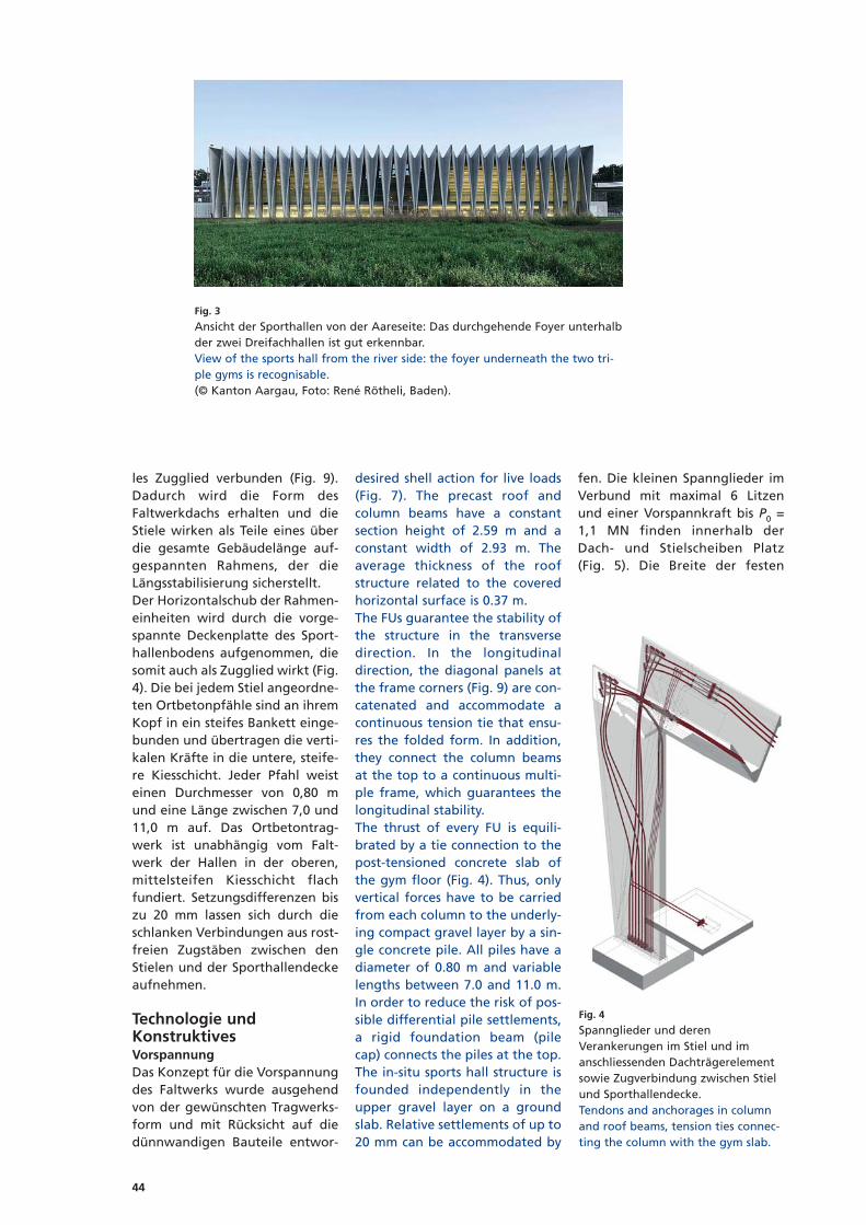
les Zugglied verbunden (Fig. 9).Dadurch wird die Form desFaltwerkdachs erhalten und dieStiele wirken als Teile eines überdie gesamte Gebäudelänge auf-gespannten Rahmens, der dieLängsstabilisierung sicherstellt.Der Horizontalschub der Rahmen -einheiten wird durch die vorge-spannte Deckenplatte des Sport -hallenbodens aufgenommen, diesomit auch als Zugglied wirkt (Fig.4). Die bei jedem Stiel angeordne-ten Ortbetonpfähle sind an ihremKopf in ein steifes Bankett einge-bunden und übertragen die verti-kalen Kräfte in die untere, steife-re Kies schicht. Jeder Pfahl weisteinen Durchmesser von 0,80 mund eine Länge zwischen 7,0 und11,0 m auf. Das Ortbetontrag -werk ist unabhängig vom Falt -werk der Hallen in der oberen,mittelsteifen Kiesschicht flachfundiert. Setzungsdifferenzen biszu 20 mm lassen sich durch dieschlanken Verbindungen aus rost-freien Zug stäben zwischen denStielen und der Sporthallendeckeaufnehmen.
Tech nologie undKonstruktivesVorspannungDas Konzept für die Vorspannungdes Faltwerks wurde ausgehendvon der gewünschten Tragwerks -form und mit Rücksicht auf diedünnwandigen Bauteile entwor-
desired shell action for live loads(Fig. 7). The precast roof andcolumn beams have a constantsection height of 2.59 m and aconstant width of 2.93 m. Theaverage thickness of the roofstructure related to the coveredhorizontal surface is 0.37 m.The FUs guarantee the stability ofthe structure in the transversedirection. In the longitudinaldirection, the diagonal panels atthe frame corners (Fig. 9) are con-catenated and accommodate acontinuous tension tie that ensu-res the folded form. In addition,they connect the column beamsat the top to a continuous multi-ple frame, which guarantees thelongitudinal stability.The thrust of every FU is equili-brated by a tie connection to thepost-tensioned concrete slab ofthe gym floor (Fig. 4). Thus, onlyvertical forces have to be carriedfrom each column to the underly-ing compact gravel layer by a sin-gle concrete pile. All piles have adiameter of 0.80 m and variablelengths between 7.0 and 11.0 m.In order to reduce the risk of pos-sible differential pile settlements,a rigid foundation beam (pilecap) connects the piles at the top.The in-situ sports hall structure isfounded independently in theupper gravel layer on a groundslab. Relative settlements of up to20 mm can be accommodated by
fen. Die kleinen Spannglieder imVerbund mit maximal 6 Litzenund einer Vorspannkraft bis P0 =1,1 MN finden innerhalb derDach- und Stielscheiben Platz(Fig. 5). Die Breite der festen
Fig. 3
Ansicht der Sporthallen von der Aareseite: Das durchgehende Foyer unterhalbder zwei Dreifachhallen ist gut erkennbar.View of the sports hall from the river side: the foyer underneath the two tri-ple gyms is recognisable.(© Kanton Aargau, Foto: René Rötheli, Baden).
Fig. 4
Spannglieder und derenVerankerungen im Stiel und imanschliessenden Dachträgerelementsowie Zugverbindung zwischen Stielund Sporthallendecke.Tendons and anchorages in columnand roof beams, tension ties connec-ting the column with the gym slab.

45
the slender stainless tie bars con-necting the column beams to thegym’s floor slab.
Technology and detailingPost-tensioningThe conceptual design for thepost-tensioning was developedtaking into account the desiredstructural form and the thin-wall -ed structural members. Thegrout ed tendons are small sizedwith up to 6 strands and a pre-stressing force of P0 = 1.1 MN, inorder to fit into the member sec-tions (Fig. 5). They require littlespace in the frame corner for thedead-end anchorages, spe ciallydeveloped for this project. Theprefabricated column beamswere post-tensioned at the facto-ry (Fig. 10). Stressing of the ten-dons was carried out from thecolumn base, where the liveanchorages are located in a com-mon block-out. Supplementarymonostrand tendons had to beprovided for the constructionphase. On the other hand, theprecast roof beams were post-tensioned only after erection of
Anker in den Rahmenecken wurdeeigens für das Projekt minimiert.Die vorfabrizierten Stiele wurdenim Werk vorgespannt (Fig. 10).Die vorkonfektionierten Spann -glie der à 4 Litzen für den End -zustand sowie zusätzliche Mono -litzenspannglieder ohne Verbundfür die Transport- und Montage -phase wurden aus einer Spann -nische am Stielfuss aktiviert. DieDachspannglieder wurden erstnach der Montage der Dachträ -ger elemente auf provisorischenTürmen und dem Beto nie renrespektive Vergiessen der Quer-und Längsfugen konfektioniert.Die Litzen wurden in dieHüllrohre eingestossen und auseiner Spannnische auf der Dach -oberseite mit kompakten Zwi -schen veranke rungen gespannt.Die Nischen wurden anschlies-send ausbetoniert und sind imEndzustand nicht erkennbar (Fig.11). Sämtliche Quer schnitte sindunter den ständigen und den ver-änderlichen Einwir kungen vorge-spannt. Die mittlere Betondruck -spannung aus der Vorspannungbeträgt σc,Ende = – 4,6 MPa.
the whole structure and concret -ing of the joints in situ. Thestrands were inserted in the ductsand stressed at intermediate an -chorages located in block-outs onthe roof ridge, which were subse-quently filled with concrete andare not visible in the final state(Fig. 11). All cross sections arecompressed under dead and liveloads: the average concrete com-pression stress due to post-ten -sion ing is σc,End = – 4.6 MPa.
Self-compacting concrete All prefabricated elements aremade of the same high-strengthself-compacting concrete (SCC) ofthe strength class C50/60. The ele-ments – with V- and Y-shape –were casted upside down to ensu-re both optimal filling of theformwork from above and a best-possible compact surface withoutair occlusions on the upper andouter faces of the members. Forthe same reasons, the maximumaggregate size was reduced to 8mm. The fair-faced concrete sur-faces are protected by hydropho-bic impregnation. The directly
Fig. 5
Längsschnitt und Querschnitte einer Rahmeneinheit mit Elementeneinteilung, Ortbetonfugen und Spanngliedern.Longitudinal and cross sections of a frame unit (FU) showing the precast roof and columns beams, the cast-in-situ jointsand the post-tensioning tendons.

46
Selbstverdichtender Beton Sämtliche Fertigteile wurden ausdem gleichen hochfesten, selbst-verdichtenden Beton (SVB) derFestigkeitsklasse C50/60 herge-stellt. Die Fertigteile für Dach undStiele mit V- respektive variablemY-Quer schnitt wurden mit denSicht flächen nach unten beto-niert, um die Schalung aus denEinfüll punk ten auf der Oberseiteoptimal zu verfüllen und damitdie im End zustand dem Regenund Wasser abfluss ausgesetztenBetonflä chen möglichst kompaktund frei von Lunkern auszubil-den. Aus den gleichen Gründenbeträgt das Grösstkorn lediglich 8mm. Sämtliche Sichtbetonflächensind durch eine Tiefenhydro -phobie rung geschützt. Die direktdem Regen ausgesetzten Stiel -flächen sind zusätzlich durch einefarblose Versiegelung geschützt.Auf der Dachaufsicht wurde voll-flächig eine UV-resistente Flüssig -kunst stoffabdichtung auf Poly -ure thanbasis aufgebracht.
Konstruktive DurchbildungDie Verbindungen zwischen demvorfabrizierten Faltwerk und demOrtbetontragwerk der Einbauten,
rain exposed sides are treatedwith a supplementary transpa-rent sealing. The roof surfaces areprotected by a UV-resistant poly -urethane liquid membrane.
Structural detailsThe connections between theprecast members and the in-situconcrete structure had to be de -sign ed to take into account theestimated differential settlementsand placement inaccuracies. Thestainless tension ties (D = 40 mm)that transfer the thrust of everyframe unit to the gym’s floor slab,were previously inserted into tu -bular openings placed in the slab,then connected to the columnbeams after their erection (Fig. 8).A 20 mm space all around the tieallows for settlements.The base point connection of thecolumn beams is realised by corres -ponding steel plates encased inthe column and in the foundationbeam, which were welded duringerection. The gap between thecolumn base and the foundationwas grouted afterwards by ahigh-strength cement grout. In -accuracies were com pen sated inadvance through levell ing and if
die unabhängig voneinander fun-diert sind, mussten so entworfenwerden, dass sie Ausführungs to -le ranzen und Differenzial setzun -gen aufnehmen können. Die rost-freien Zugglieder (D = 40 mm),die den Horizontalschub vonjedem Stiel zur Sporthallendeckeübertragen, wurden vorgängig inRohreinlagen der Decke einge-führt und nach Errichten desStiels mit einem Muffenstoss an -geschlossen (Fig. 8). Ein freierZwischenraum von 20 mm umden Stab ermöglicht allfälligeDifferenzialsetzungen. Stiel undFundations ban kett werden durchdas Ver schweis sen von eingeleg-ten Stahlplatten bei der Montageverbunden. Die schmale Fugezwischen Stielfuss und der Funda -mentaussparung wird anschlies-send durch einen hochfestenVergussmörtel verfüllt. Die Aus -führungs tole ran zen wurden vor-gängig durch das Nivellieren derEinlagen im Bankett und bei Be -darf mit Schiftplatten ausgegli-chen.
HerstellungFür die Herstellung der kurzenund langen Stiele sowie für die
Fig. 6
Gerüsttürme für die temporäreAbstützung der Dachträger.Temporary support of the roof beamsusing falsework.
Fig.8
Rostfreie Zugglieder für dieVerbindung zwischen Stiel undSporthallendecke.Stainless ties between the gym slaband one column beam.
Fig. 7
Nischen und Stahlplattenverbindungin den 3 cm breiten Längsfugen ander Dachoberkante.Block-outs for welding plate connec-tions in the 3 cm-wide gap on theroof ridge.

47
Autoren/Authors
Massimo LaffranchiDr. sc. techn., dipl. Bauing. [email protected]
Armand FürstDr. sc. techn., dipl. Bauing. [email protected]
Fürst Laffranchi Bauingenieure GmbHCH-4628 Wolfwil
Fig. 11
Vorspannung der Dachträger auf derBaustelle dankZwischenverankerungen an derDachaufsicht.Post-tensioning of the roof beams insitu by means of intermediateanchorages.(© VSL AG, Subingen).
Fig.9
Zugglieder in der Diagonalscheibeunter Dach im Rahmeneck vor demBetonieren der Aussparung.Tension tie in the diagonal panel atthe frame corner before concreting.
Fig. 10
Vorspannung der Stiele im Werk,Ankernische und Stahl-Fussplatten.Post-tensioning of the column beamsat the factory, block-out and steelbase plates.(© VSL AG, Subingen).
necessary by means of supplemen -tary steel plates.
ConstructionThe short and long column beamsas well as the midspan and lateralroof beams all required their spe-cific steel formwork. Thus, thefour element types were manu-factured simultaneously in onefactory and in a work cycle of 2 to3 days per element. The concretecomposition was optimised toachieve a rapid development ofstrength. The rotating of theheavy elements, which were castupside down, required a specialmechanism.The handling and assembling ofthe precast elements was carriedout with the aid of a 500 t craw-ler crane placed beside the hall.The roof beams were carried bytemporary falsework until thepost-tensioning was completed.The lowering of the falseworkwas controlled by a system ofhydraulic jacks. The erection ofthe large span structure requireda total time of 4 months. The costs for the sports hall inclu-sive of technical equipment are of25 million Swiss Francs.
mittleren respektive die seitlichenFertigteile des Dachs waren insge-samt vier Schalungen erforder-lich. Die vier Elementtypen konn-ten daher parallel in einem einzi-gen Werk in Zyklen von zwei bisdrei Tagen pro Bauteil produziertwerden. Die Betonmischung wur -de für eine rasche Festi g keits ent -wicklung optimiert. Das Drehender schweren, auf der Kopfseitebetonierten Fertigteile erforderteeine besondere Drehvorrichtung.Montiert wurden die Fertigteilemithilfe eines 500-t-Raupenkrans,der neben der Sporthalle zusam-mengebaut worden war. Die Dach -träger wurden bis zu ihrer Vor -spannung von Gerüsttürmen ge -tra gen (Fig. 6). Diese wurden überein System von hydraulischenPressen abgesenkt, deren Kräftesich fein steuern liessen. DieErrichtung des Faltwerks in zweiPhasen erforderte insgesamt vierMona te, die Kosten der Sport hallein klu sive Ausbau und technischerAusrüstung betragen 25 Millio -nen Franken.

Brücken
Ponts
Bridges

100
IntroductionPièce maîtresse du Projet Poya quivise à relier les quartiers duSchönberg et du Palatinat afin dedésengorger le centre-ville de Fri -bourg, le pont de la Poya franchitla vallée de la Sarine, au-dessusde la STEP, à une hauteur d’envi-ron 70 m. Au Nord, l’ouvragepénètre dans un versant boisé etescarpé, jusqu’au tunnel de Pa la -tinat. Au Sud, l’ouvrage s’incurveet s’élargit pour rejoindre le car-refour Schönberg.La conception de l’ouvrage et sonanalyse structurale constituent lepremier défi technique majeur duprojet. Sa réalisation dans un ver-sant de stabilité précaire côtéPalatinat et le recours à des mé -thodes de construction novatricesconstituent le deuxième enjeuprincipal du projet. La portée centrale de 196 m con-stitue le nouveau record de por-tée en Suisse.
HistoriqueLe groupement d’ingénieurs GIPPa remporté le concours de projetdu Pont de la Poya, organisé parla Ville de Fribourg, en 1989, il y aplus de 24 ans. Un premier projetd’ouvrage est déposé en 1991 surle tracé du concours de projet. Undeuxième projet d’ouvrage est éla -
IntroductionThe centre-piece of the Poya pro-ject, which connects the suburbsof Schönberg and Palatinat inorder to ease traffic congestion inthe centre of the town of Fri -bourg, is the Poya bridge crossingthe Sarine valley above the waste-water treatment plant at a heightof about 70 m. To the north thestructure penetrates into a side ofthe valley that is wooded andsteep up to the Palatinat tunnel.To the south the structure curvesand widens to connect with theSchönberg junction.The design of the structure andits structural analysis form thefirst major challenge of the pro-ject. To achieve this in the case ofa hillside with precarious stabilityon the Palatinat side and the re -course to innovative methods ofconstruction is the second majorchallenge of the project. The central span of 196 m is a newrecord for a span in Switzerland.
HistoryIn 1989, the GIPP joint venture ofengineers won the competitionfor the Poya bridge project orga-nised by the town of Fribourg,more than 24 years ago. An initi-al design for the structure wassubmitted in 1991 as the competi-
boré en 2008 sur un tracé sensi-blement modifié, sous la directiondu Service des ponts et chausséesdu canton de Fribourg.Les travaux ont débuté en autom-ne 2009; l’achèvement du gros-œuvre a été réalisé en automne2013.
GéologieLe toit de la molasse saine, essen-tiellement gréseuse et de bonnecapacité portante, affleure sousl’ensemble de l’ouvrage, à uneprofondeur comprise entre 0 et16 m. Côté Palatinat, la molassesaine est recouverte d’alluvionsinterglaciaires et de moraine ainsique d’éboulis de pente et de mo -lasse altérée. Des alluvions inter-glaciaires, fluvioglaciaires et gla-ciolacustres ainsi que des éboulisde pente et de la molasse altéréesont présents côté Schönberg.Le fond de la vallée est recouvertpar des alluvions de la Sarine etdes remblais. Les couches superfi-cielles des versants inclinés pré-sentent une stabilité précaire,aussi bien côté Palatinat que côtéSchönberg.
Conception générale del’ouvrageD’une longueur totale de 851,6 m,l’ouvrage avec tablier en structure
Le Pont de la PoyaThe Poya bridge
Bernard Houriet, Pierre Gorgé, Sylvain Plumey, Aldo Bisetti, Jean-François Gnaegi
Fig. 1
Coupe longitudinale de l’ouvrage et profil géologique.Longitudinal section of the structure and geological profile.

101
tion for the project. A seconddesign for the structure was pre-pared in 2008 as the project pro-gressed in a way that was signifi-cantly modified under the directi-on of the Highways and BridgesDepartment of Canton Fribourg.Work started in the autumn of2009, and this large project wascompleted in 2013.
GeologyThe upper part of the sound mo -lasse, essentially sandstone with agood load-carrying capacity, risesalmost to ground level under thewhole structure, at a depth ofbet ween 0 and 16 m. On the Pa -latinat side the sound molasse iscovered with interglacial alluvialdeposits as well as some boulderscree and some altered molasse.Interglacial alluvial, fluvioglacialand glaciolacustrine deposits aswell as some boulder scree andsome weathered molasse are pre-sent on the Schönberg side. The bottom of the valley is cover-ed by alluvial deposits from theSarine river with some outcropp -ing rocks. The surface layers of theinclined sides have a precariousstability, both on the Palatinatside and on the Schönberg side.
General design of thestructureWith a total length of 851.6 m thecivil engineering structure with abridge deck made of a mixedsteel-concrete design includes thefollowing three distinct parts(Fig.1):
mixte acier-béton comprend lestrois parties distinctes suivantes(Fig. 1) :− Le viaduc d’accès Palatinat de
252,6 m de longueur, essentiel-lement réalisé par lancementpréalable de l’ossature métalli-que.
− Le viaduc d’accès Schönberg de231 m de longueur, réalisé parpose conventionnelle de l’ossa-ture métallique.
− L’ouvrage haubané central de368 m de longueur, muni d’unesuspension latérale en semi-harpe, réalisé par encorbelle-ment haubané.
TablierL’ensemble du tablier est conçu enossature mixte acier-béton avecdes entretoises métalliques deforme trapézoïdale de 1,05 m dehauteur maximale, espacées de6,0 m. Deux poutres maîtressescomposées soudées à âme pleinede 2,05 m de hauteur sont adop-tées dans les viaducs d’accès (Fig.2). La hauteur des deux poutresmaîtresses est réduite linéaire-ment de 2,05 m à 1,05 m au droitdes piles 5 et 8 adjacentes à lazone haubanée. Deux poutres la -térales composées soudées à âmepleine inclinée complètent l’ossa-ture métallique en grille de pou-tre dans la zone haubanée (Fig.3).
Système statiqueLe système statique de l’ouvrageest flottant sur 851,6 m de lon -gueur en phase d’exploitation. Le
− The 252.6 m long Palatinat ac -cess viaduct was basically con-structed by previously launch -ing the steel framework.
− The 231 m long Schönbergaccess viaduct was basicallyconstructed by conventionaluse of falsework.
− The 368 m long central cable-stayed structure of the semi-harp type, also providing late-ral bracing.
Bridge deckThe bridge deck was designed asa composite steel-concrete unitwith steel crossbrackets of trape-zoidal shape 1.05 m maximumheight, spaced at 6.0 m. Two maingirders welded with a plain web2.05 m high were used in theaccess viaducts (Fig. 2). The heightof the two main girders is reduc -ed linearly from 2.05 m to 1.05 mfrom piers 5 and 8 adjacent to thecable-stayed zone. Two lateralgirders welded with an inclinedweb complete the steel deck gril-lage in the cable-stayed zone(Fig.3).
Structural systemThe structural system is a floatingsystem over a length of 851.6 m inthe operational phase. The bridgefloor is provisionally supported atthe two abutments in the longitu-dinal direction during the erecti-on phases. Pylons 6 and 7 are con-nected monolithically to thebridge deck and ensure the longi-tudinal stability of the structurewhen it is in use. The flexible piers
Fig. 2
Tablier, section transversale des viaducs d’accès.Bridge floor, transverse section of the access viaducts.
Fig. 3
Tablier, section transversale de la zone haubanée.Bridge floor, transverse section of the cable-stayed zone.

102
tablier est bloqué provisoirementaux deux culées dans le sens lon-gitudinal pendant les phases demontage. Les mâts 6 et 7 sont liésmonolithiquement au tablier etassurent la stabilité longitudinalede l’ouvrage en phase d’exploita-
3, 4, 5 and 8 are connected longi-tudinally to the bridge deck; allthe piers are connected transver-sely to the bridge floor by one ofthe two bearings. Two pot bear -ings free to move in all directionsand one bearing for longitudinal
tion. Les piles souples 3, 4, 5 et 8sont connectées longitudinale-ment au tablier ; toutes les pilessont liées transversalement autablier par l’un des deux appuis.Deux appuis pots mobiles en toussens et un appui de guidage lon-
Fig. 4
Mâts, étude de variantes.Pylons, study of the variants.
béquilles supé-rieures inclinées
béquilles infé-rieures inclinées
fût vertical
Fig. 5
Mât 6, coupe longitudinale, élévation et sections transversales.Pylon 6, longitudinal section, elevations and transverse sections.

103
guiding are provided at abut-ments 0 and 13.
BracingThe bracing (cable-stays) of eachcantilever beam section consists oftwo lateral planes in semi-harps of2 x 7 cables (bracing in umbrella).The 7 cables are made up of 2 x 31,3 x 37, and 2 x 55 strands of150 mm2 of nominal section pro-vided with an individual tripleprotection against corrosion:− The strands are formed of 7
galvanised wires.− The strands are fitted with an
individual protective sheathmade of high density polyethy-lene.
− The wires are protected by waxinside the individual sheath.
The strands are installed indivi-dually and tension is appliedusing the so-called “isotensionprocedure”, which enables a uni-form tension to be obtained in allthe strands of the same cable.This design drastically reduces thelifting requirement necessary andsimplifies both the fitting of thecables and their possible replace-ment in the maintenance schedu-le of the structure.The fixed anchoring of the cablesis situated at the level of thebridge floor. The mobile anchor-age and the tensioning are achiev -ed in the pylons, inside the steelframework accessible from thebridge deck.
FoundationsPiers 2 to 5 and 8 are founded inthe sound molasse by means of 2shafts with a full section of 2.4 mnominal diameter. Piers 6 and 7are also founded in the sound
gitudinal sont prévus aux culées 0et 13.
HaubanageLe haubanage de chaque fléauest constitué de deux nappes laté-rales en semi-harpes de 2 x 7 hau-bans (haubanage en parapluie).Les 7 haubans sont constitués de2 x 31, 3 x 37 et 2 x 55 torons de150 mm2 de section nominalepour vus d’une triple protectionin dividuelle contre la corrosion:− Les torons sont constitués de 7
fils galvanisés.− Les torons sont munis d’une
gaine de protection individuelleen polyéthylène à haute densité.
− Les fils sont protégés par unecire à l’intérieur de la gaine in -di viduelle.
Les torons sont mis en place indi-viduellement et mis en tensionselon le procédé d’isotension quipermet d’obtenir une tension uni-forme dans tous les torons d’unmême hauban. Ce concept réduitdrastiquement les moyens de le -vage nécessaires et simplifie aussibien le montage des haubans queleur remplacement éven tuel, dansle cadre du plan d’entretien del’ouvrage.L’ancrage fixe des haubans estsitué au niveau du tablier. L’an -crage mobile et la mise en tensionsont réalisés dans les mâts, à l’in-térieur d’une ossature métalliqueaccessible depuis le tablier.
FondationsLes piles 2 à 5 et 8 sont fondéesdans la molasse saine au moyende 2 puits de section pleine de2,4 m de diamètre nominal. Lesmâts 6 et 7 sont également fon-dés dans la molasse saine à l’aide
molasse with the aid of 12 drivensteel tube piles of 1.5 m nominaldiameter. Piers 1 and 9 to 12 aswell as the abutments are foun-ded on unconsolidated groundon foundation slabs.
PylonsThe structural and architecturaldesign of the pylons was the sub-ject of a detailed analysis, suppor-ted by numerous variants (Fig. 4).The idea of the bridge deck pass -ing through a pylon with a dia-mond (lozenge) shape, which wasthe symbol of the solution regis -tered during the competition forthe project in 1989, was retainedwith the following adaptations:− The shapes have been improv -
ed and simplified by the remo-val of the majority of the groo-ves initially planned.
− The use of an enlarged verticalshaft of hexagonal shape en -abled the transition and thecohesion between the verticalshaft of great height and theupper lozenge to be improved(Fig. 5).
Models for calculation andstructural analysisThe overall structural analysis inthe assembly and operationalpha ses has been done with the aidof a computational model with3D frame members (Fig. 6). Thestructural behaviour of the bridgedeck, the steel construction andthe anchorages was assessed us -ing global and local shell models(Fig. 7 and 8). The structural de -sign of the pylons is dictated bythe loading in the operationalphase. Some stabilisation measu-res are required in the erectionphase to resist the loading duringerection due to the wind and tothe asymmetric concreting of therunning surface (Figs. 9 and 10).
Erection procedure, pro-gress of the workExcavations and foundationsThe important excavation on thePalatinat side as well as the exca-vations of piers 2 to 5 and 8 wascarried out in the sloping groundwith precarious stability by meansof walls anchored and pinned.
OwnerState of Fribourg, Bridges andHighways DepartmentAgentsProject: GIPP by GVH Tramelan SADLT: MPP by GVH Tramelan SAContractorsImplenia Constructions SA, Grisoni-Zaugg SA, Routes Modernes SASub-contractorsZM SA (steel construction), FreyssinetSA (cables and prestressing), MagebaSA (bearings and expansion joints)
Maître d’ouvrageEtat de Fribourg, Service des ponts etchausséesMandatairesProjet : GIPP par GVH Tramelan SADLT: MPP par GVH Tramelan SAEntreprisesImplenia Constructions SA, Grisoni-Zaugg SA, Routes Modernes SASous-traitantsZM SA (construction métallique),Freyssinet SA (haubans et précon-trainte), Mageba SA (appuis et jointsde chaussée)

104
de 12 pieux forés tubés de 1,5 mde diamètre nominal. Les piles 1et 9 à 12 ainsi que les culées sontfondées en terrain meuble sur se -melles superficielles.
MâtsLa conception structurale et archi-tecturale des mâts a fait l’objetd’une analyse détaillée, étayéepar de nombreuses variantes (Fig.4). Le concept de franchissementdu tablier au travers d’un mât enforme de losange, qui constituaitle symbole de la solution déposéelors du concours de projet de1989, a été conservé avec lesadaptations suivantes :− Les formes ont été épurées et
simplifiées par la suppression
The excavation of pylon 6 wasalso done with the help of a pin-ned wall; an enclosure of water-tight sheet piles was required forthe excavation of pylon 7 situatedon the bank of the Sarine.
Piers and pylonsThe vertical shaft of hollow hexa-gonal section of the piers andpylons was executed by means ofclimbing formwork with steps ofbetween 3.3 and 4.2 m. The headof the piers of triangular shapeand the upper part of the pylonsof diamond shape ne cessitatedsome special shoring and stabili-sation measures (Fig. 11).The vertical reinforcement of thepiers and the pylons was basically
de la plupart des rainures ini -tialement prévues.
− Le recours à un fût verticalélargi de forme hexagonale apermis d’améliorer la transitionet la cohérence entre le fût ver-tical de grande hauteur et lelosange supérieur (Fig. 5).
Modèles de calcul et analyse structuraleL’analyse structurale globale enphases de montage et d’exploita-tion a été menée à l’aide d’unmodèle barres 3D (Fig. 6). Le com-portement structural du tablier,de l’ossature métallique et desancrages a été évalué au moyende modèles coques globaux etlocaux (Fig. 7 et 8).La conception structurale des mâtsest dictée par les sollicitations enphase d’exploitation. Des mesuresde stabilisation sont requises enphase de montage pour couvrirles sollicitations au montage duesau vent et au bétonnage asymé -trique de la dalle de roulement(Fig. 9 et 10).
Procédé de montage,déroulement des travauxFouilles et fondationsL’importante fouille Palatinat ain sique les fouilles des piles 2 à 5 et 8ont été réalisées dans des versantsde stabilité précaire au moyen deparois ancrées et clouées.La fouille du mât 6 a égalementété réalisée à l’aide d’une paroiclouée; une enceinte de palplan-ches étanche a été requise pour lafouille du mât 7 situé sur la bergede la Sarine.
Piles et mâtsLe fût vertical de section hexago-nale creuse des piles et des mâts aété réalisé aux moyen de coffra-ges grimpants avec des étapescomprises entre 3,3 et 4,2 m. Latête des piles de forme triangulai-re et la partie supérieure des mâtsen forme de losange ont nécessitédes mesures d’étayage et de sta -bilisation particulières (Fig. 11).L’armature verticale des piles etdes mâts a été essentiellementcon çue à l’aide de cages préfabri-quées munies d’étriers fermés.L’entretoise des mâts est pourvue
Fig. 7
Haubans, ancrages fixes, analyse des contraintes.Cables, fixed anchorages, analysis of the stresses.
Fig. 8
Haubans, ancrages mobiles, analyse des contraintes.Cables, mobile anchorages, analysis of the stresses.
Fig. 6
Modèle de calcul barres 3D (logiciel Statik5).Model of 3D calculation with frame members (Statik5 software).

105
designed with the help of prefa-bricated cages fitted with closedstirrups. The crosspiece of thepylons is provided with a lightparabolic prestress exerted by 16cables of 19, T15 strands.
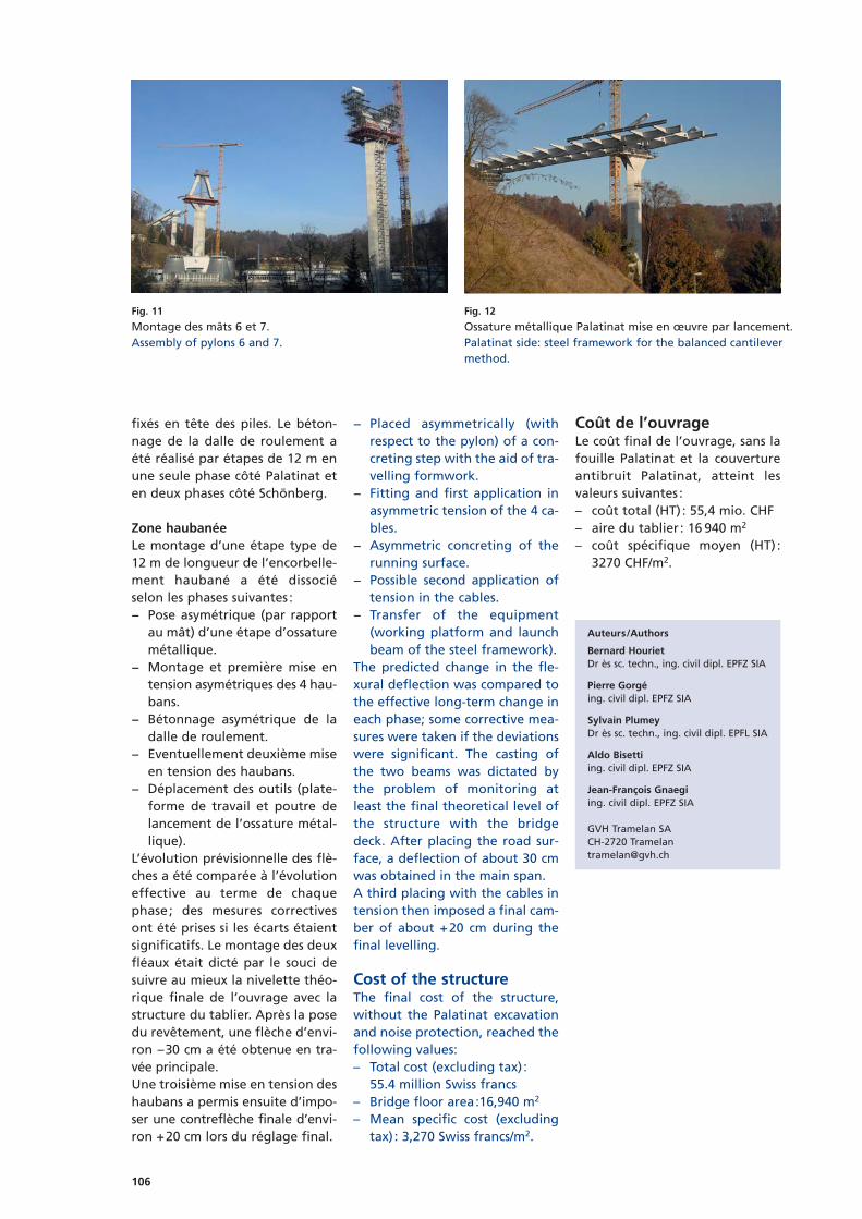
Access viaductThe launching of the rectangularsteel framework on the Palatinatside was carried out without pro-visional bracing of the slenderpiers 3 to 5, by means of a noseend fitted with a lifting device torest on the piers (Fig. 12).
d’une précontrainte légèrementparabolique constituée de 16câbles de 19 torons T15.
Viaduc d’accèsLe lancement de la zone rectili-gne de l’ossature métallique côtéPalatinat a été réalisé sans hauba-nage provisoire des piles élancées3 à 5, au moyen d’un avant-becmuni d’un dispositif de relevagepour accoster les piles (Fig. 12).Côté Schönberg, l’ossature métal-lique a été posée à l’aide de gruesmobiles et d’appuis provisoires
On the Schönberg side, the false-work was placed with the help ofmobile cranes and provisionalbearings fixed at the top of thepiers.The concreting of the runningsurface was carried out in steps of12 m in a single phase on the Pa -la tinat side and in two phases onthe Schönberg side.
Cable-stayed zoneThe assembly of a step 12 m longof the braced corbel was brokendown into the following phases:
Fig. 10
Stabilisation diagonale provisoire du fléau 7.Provisional diagonal stabilisation of beam 7.
Fig. 9
Stabilisation verticale provisoire du fléau 6.Provisional vertical stabilisation of beam 6.
106
fixés en tête des piles. Le béton-nage de la dalle de roulement aété réalisé par étapes de 12 m enune seule phase côté Palatinat eten deux phases côté Schönberg.
Zone haubanéeLe montage d’une étape type de12 m de longueur de l’encorbelle-ment haubané a été dissociéselon les phases suivantes :− Pose asymétrique (par rapport
au mât) d’une étape d’ossaturemétallique.
− Montage et première mise entension asymétriques des 4 hau -bans.
− Bétonnage asymétrique de ladalle de roulement.
− Eventuellement deuxième miseen tension des haubans.
− Déplacement des outils (plate-forme de travail et poutre delancement de l’ossature métal-lique).
L’évolution prévisionnelle des flè-ches a été comparée à l’évolutioneffective au terme de chaquephase ; des mesures correctivesont été prises si les écarts étaientsignificatifs. Le montage des deuxfléaux était dicté par le souci desuivre au mieux la nivelette théo-rique finale de l’ouvrage avec lastructure du tablier. Après la posedu revêtement, une flèche d’envi-ron –30 cm a été obtenue en tra-vée prin cipale.Une troisième mise en tension deshaubans a permis ensuite d’impo-ser une contreflèche finale d’en vi -ron +20 cm lors du réglage final.
− Placed asymmetrically (withrespect to the pylon) of a con-creting step with the aid of tra-velling formwork.
− Fitting and first application inasymmetric tension of the 4 ca -bles.
− Asymmetric concreting of therunning surface.
− Possible second application oftension in the cables.
− Transfer of the equipment(working platform and launchbeam of the steel framework).
The predicted change in the fle-xural deflection was compared tothe effective long-term change ineach phase; some corrective mea-sures were taken if the deviationswere significant. The casting ofthe two beams was dictated bythe problem of monitoring atleast the final theoretical level ofthe structure with the bridgedeck. After placing the road sur-face, a deflection of about 30 cmwas obtained in the main span.A third placing with the cables intension then imposed a final cam-ber of about +20 cm during thefinal levelling.
Cost of the structureThe final cost of the structure,without the Palatinat excavationand noise protection, reached thefollowing values:– Total cost (excluding tax) :
55.4 million Swiss francs– Bridge floor area:16,940 m2
– Mean specific cost (excludingtax) : 3,270 Swiss francs/m2.
Coût de l’ouvrageLe coût final de l’ouvrage, sans lafouille Palatinat et la couvertureantibruit Palatinat, atteint lesvaleurs suivantes :– coût total (HT) : 55,4 mio. CHF– aire du tablier : 16 940 m2
– coût spécifique moyen (HT) :3270 CHF/m2.
Auteurs/Authors
Bernard HourietDr ès sc. techn., ing. civil dipl. EPFZ SIA
Pierre Gorgéing. civil dipl. EPFZ SIA
Sylvain PlumeyDr ès sc. techn., ing. civil dipl. EPFL SIA
Aldo Bisettiing. civil dipl. EPFZ SIA
Jean-François Gnaegiing. civil dipl. EPFZ SIA
GVH Tramelan SACH-2720 [email protected]
Fig. 12
Ossature métallique Palatinat mise en œuvre par lancement.Palatinat side: steel framework for the balanced cantilevermethod.
Fig. 11
Montage des mâts 6 et 7.Assembly of pylons 6 and 7.

Ingenieurbau
Génie civil
Civil engineering

132
Einleitung Die Durchmesserlinie kann als ak -tuellstes Kapitel in der Erfolgs ge -schichte des öffentlichen Verkehrsim Raum Zürich gelesen werden:Als die S-Bahn im Jahr 1990 ihrenBetrieb aufnahm, nutzten täglich160 000 Reisende den ZürcherHauptbahnhof. Heute ist die Zahlauf 400 000 angestiegen, was denHauptbahnhof als wichtigstenKno tenpunkt des Bahnverkehrs anseine Kapazitätsgrenzen ge brachthat. Die SBB und der KantonZürich haben darauf mit der Pla -nung einer Bahn hofser weite rungreagiert, die nun unter der Pro -jektbezeichnung «Durch messer -linie» schon weitgehend Gestaltangenommen hat. Politisch stehtdas Bauwerk auf solidem Grund:Im Jahr 2001 stimmten 82% desZürcher Stimmvolks dem 2-Milli ar -den-Projekt zu. Gebaut wird damiteine 9,6 Kilometer lange Bahn -strecke von Altstetten via Haupt -bahnhof nach Oerlikon. Das Kern -stück der Strecke bildet der unter
Introduction The Cross-City Line is the latestchapter in the history of publictransport in the Zurich area.When the S-Bahn started opera-ting in 1990, 160,000 passengersused Zurich Central Station everyday. Today the figure has risen to400,000, which has brought theCentral Station, which is thebusiest rail intersection to itscapacity limit. Therefore the SBB(Swiss Federal Railways) andCanton Zurich decided to under-take the planning of a station ex -tension, which has begun to takeshape under the project name ofthe ”Cross-City Line”. Politically theproject stands on solid ground: In2001, 82% of the Zurich electora-te voted for the 2 billion francproject. Thus a 9.6 kilometre longrailway line was built fromAltstetten via Central Station toOerlikon. The centre-piece of theline is the Löwenstrasse Stationsituated under the existing tracksof Zurich Central Station. This
den bestehenden Gleisen desZürcher Hauptbahnhofs liegendeDurchgangsbahnhof Löwen stras se.Mitte 2014 soll die aus vier Glei -sen bestehende Anlage ihren Be -trieb aufnehmen (Fig. 1).
Bau des Tiefbahnhofs Verschachtelter UntergrundDie Anlage bildet einen sowohlbautechnisch als auch logistischsehr komplexen Abschnitt. Unterengen innerstädtischen Platzver -hält nis sen entsteht ein neues,gigantisches Bauwerk, ohne dasses von aussen wahrgenommenwerden könnte: Praktisch dergesamte Neu bau entsteht unter-irdisch, gebaut wird hauptsäch-lich mit der «Deckelbauweise»und im Bereich der neuen Fuss -gänger pas sagen unterhalb vonGleishilfs brücken. Der umbauteRaum fasst rund 320 000 m3. DieBaumass nahme am grössten undwichtigs ten Verkehrsknoten punktist vergleichbar mit einer Ope ra ti -on am offenen Herzen. Während
Tiefbahnhof Löwenstrasse der Zürcher DurchmesserlinieLöwenstrasse underground station on the Zurich Cross-City Line
Martin O. Bachmann, Valentin Rabitsch
Fig. 1
Übersicht über die Abschnitte der Durchmesserlinie.Overview of the sections of the Cross-City Line.

133
four-platform through stationwill go into service in the middleof 2014 (Fig. 1).
Construction of the under-ground station Underground complexIt is the most complex section ofthe project, both from the con-structional and from the logisticspoint of view, because with therestricted space conditions of theinner city a very large new struc-ture is being produced that can-not be seen from outside: In prac-tice the completely new under-ground structure is executedmainly by the top-down methodand in the region of the pedestrianpassageways with the aid of tem -porary track bridges. The utilisedspace comprises some 320,000 m3.The construction work at Switzer -land’s biggest and most impor-tant traffic intersection is compa-rable to open heart surgery.Throughout the whole of theconstruction time the CentralStation and the traffic intersectionpoint for suburban, intercity andlong-distance traffic, as well asthe shopping centre, have toremain in operation with no
der gesamten Rohbauphase mussder Hauptbahnhof sowohl als Ver -kehrsknotenpunkt für Nah- undFernverkehr als auch als Einkaufs -zentrum uneingeschränkt in Be -trieb bleiben. Ferner muss die his -torische Bausubstanz der Bahn -hofsgebäude geschützt und er -hal ten bleiben, und die Anforde -rungen an die Sicherheit der Bau -arbeiten sowie die Emissionensind sehr hoch. Hinzu kommt dieSihl, die von den Gleisen derDurchmesserlinie unterquert wirdund bei Hochwasser weitere si -cherheits- und bautechnische Zu -satz massnahmen bedingt (Fig. 2).
Das Teilprojekt «Querhalle» Der Bau des Bahnhofs Löwen -strasse erfolgte im Wesentlichenin fünf Teilprojekten, deren öst-lichstes unterhalb der Querhalledes Hauptbahnhofs liegt und andie Unterfahrung des historischenSüdtrakts grenzt. Das Teilprojektbesteht aus der Brandlüf tungs -zentrale, der Passage Löwenstras -se, einem Technikgeschoss unddem darunterliegenden Abschnittdes neuen Perrongeschosses. DerBahnhof besteht aus vier Gleisenund zwei Mittelperrons.
restrictions. In addition, the histo-ric fabric of the station buildinghad to be protected and main -tain ed and the requirements forthe safety of the constructionwork, as well as for the emissionsare very high. In addition, theriver Sihl runs beneath the tracksof the Cross-City Line and at highgroundwater levels this requiresfurther safety and constructionalmeasures (Fig. 2).
The Transverse Hall Löwenstrasse Station is basicallydivided into five parts, the mosteasterly of these lying below theTransverse Hall of the CentralStation and borders on the under-crossing of the historic building ofthe southern wing. The sub-pro-ject consists of the fire ventilationplant for the removal of smoke,the Löwenstrasse Passage, a storeywith technical equipment. andthe underlying section of the newplatform storey consisting of fourtracks with two island platforms.
The Löwenstrasse PassageThe Löwenstrasse Passage retainsits current function in the recon-structed station. However, with
Fig. 2
Grundriss des Zürcher Hauptbahnhofs (oben) sowie Grundriss und Längsschnitt des Bahnhofs Löwenstrasse.Ground plan of Zurich Central Station (above) as well as ground plan and longitudinal section of Löwenstrasse Station.

134
Die Passage LöwenstrasseDie Passage Löwenstrasse bleibtin ihrer jetzigen Funktion auch imneu umgebauten Bahnhof beste-hen. Sie wird jedoch mit Aus nah -me der Decke komplett abgebro-chen, erneuert und gegen Westenhin um die Halle Löwenstrasseerweitert. Das darüberliegendeGepäckgeschoss und die Quer -halle bleiben dabei ständig in Be -trieb. Das bestehende Trag werkwird von zwei Schlitzwänden undzwei auf Bohrpfählen fundiertenStützenreihen getragen. Die Passage Löwenstrasse ist einwichtiger Fussgängerbereich, derwährend der gesamten Bauar -beiten auf einer Mindestbreitebegehbar bleiben muss. Es wirddeshalb etappenweise vorgegan-gen, die Abfangung der beidenseitlichen Stützenreihen, der Aus -hub und der Bau des neuen Zwi -schengeschosses, dessen Deckeden Boden der erneuerten Pas sa -ge bildet, erfolgen zeitlich ver-setzt (Fig. 3).
Die BrandlüftungszentraleDie drei unterirdischen Technik -geschosse der Brandlüftungs zen -trale reichen vom Perrongeschossdes neuen Bahnhofs Löwenstras -se bis zur Oberfläche. Für ihren
the exception of the roof it hasbeen completely demolished, re -placed and extended westwardsaround the Löwenstrasse Hall.The luggage hall that lies above itand the Transverse Hall remainedcontinuously in use. The existingstructure is carried by two dia-phragm walls and two rows ofcolumns supported on boredpiles. The Löwenstrasse Passage is animportant pedestrian area, a mi -nimum width of which had to beaccessible throughout the wholeof the construction work. The lat-ter was carried out therefore instages, with the underpinning ofthe two side rows of columns, theexcavation and the building ofthe new intermediate floor, theslab forming the floor of thereconstructed passage, were car-ried out at different times (Fig. 3).
The fire ventilation plantThe three underground storeyshousing technical equipment forthe fire ventilation plant stretchfrom the platform storey of thenew Löwenstrasse Station up tothe surface. For their construction,besides the previous demolishingof the post office building, consi-derable underpinning and stabili-
Bau sind nebst dem vorgängigenRückbau des Postanbaus umfang-reiche Abfangungen und Stabili -sie rungen des südwestlichen Flü -gels des historischen, unter Denk -malschutz stehenden Südtraktserforderlich. Die Unterfangungenbestehen hauptsächlich aus Klein -bohrpfählen, die während desAushubs kontinuierlich zu Fach -wer ken verschweisst werden,sowie aus Schlitzwandpfeilernund Jettingkörpern. Diese wur-den mit Hochdruckinjektionenteils von OK Terrain, teils aus Kel -lerräumen heraus im anstehen-den Sihlschotter erstellt (Fig. 4).
Der SüdwesttraktMit der Auflage der Denkmal -pflege, auch die bestehendeinnen liegende Bausubstanz zuschützen, stellte sich die Aufgabeeiner Abfangung nicht nur derFassade, sondern eines ganzenGebäudeflügels – mit entspre-chend kleinen zulässigen Verfor -mun gen. Um Setzungen und Rissewährend der Bauarbeiten mög-lichst zu verhindern, wurde imErdgeschoss ein räumliches Stahl -fachwerk eingebaut (Fig. 5).Ein automatisches, dreidimensio-nales Überwachungssystem ausmeh reren Tachymetern und
Fig. 3
Für den Bau abgefangene Passage Löwenstrasse.Löwenstrasse Passage underpinned during construction work.(© Marco Püntener)

135
sation work for the historic listedbuilding of the south west wingof the station were necessary. Theunderpinning consisted mainly ofsmall bored piles, which duringthe excavation were continuallywelded to form frameworks, aswell as of diaphragm wall pilesand jet-grouted bodies of soil.These were produced with high-pressure injection partly from theground surface and partly frombasement rooms situated in theSihl river gravel (Fig. 4).
The south west wingTo conform with the require-ments to protect not only theappearance of the historic build -ing but also the interior structurethe task was to underpin not onlythe façade, but also a completewing of the building – with corre-spondingly small permissible de -for mations. In order to prevent,as far as possible, settlement andcracks during the constructionwork a three-dimensional steelframework was installed on theground floor (Fig. 5).An automatic, three-dimensionalcontinuous monitoring systemconsisting of several tacheome-ters and a settlement gauge mea-suring the water level in a tube
Schlauch waagen kontrolliert lau-fend die Verformungen undSetzungen. Hydraulische Pressenkönnen allfällige Setzungen derprovisorischen Tiefgründungen,auf denen die bestehenden Bau -ten fundiert sind, im Laufe derAushubarbeiten kompensieren.Die Pfahlfundation muss alle ver-tikalen und horizontalen Lastenmöglichst setzungsarm gezielt bisin den Baugrund ableiten. Dieoberirdischen Geschosse wurdenmit horizontalen und vorge-
checks for deformations and sub-sidence. Hydraulic presses cancompensate any settlement ofthe provisional deep foundationson which the existing buildingsare supported, in the course ofthe excavation work. The pilefoun dation must divert all verticaland horizontal loads with as littlesettlement as possible into theground. The storeys aboveground were stabilised with hori-zontal and pre-stressed tensilebars in order to prevent unaccep-
Fig. 5
Stabile Abfangung des Südwesttrakts mit einem räumlichen Fachwerk.Stable underpinning of the southwest wing with a space frame.(© Marco Püntener)
Fig. 4
Kleinbohrpfahl-Türme für die Unterfangungen.Small bored pile towers for the underpinning.(© Marco Püntener)

136
spannten Zugstangen stabilisiert,um unzulässige Deformationenund instabile Zustände (z.B. Aus -knicken der Fassade) zu verhin-dern. Im Gebäude sind Laden -lokale und Büros eingemietet, dievon den Bauarbeiten so wenig alsmöglich tangiert werden sollten.
BaumethodenDer generelle Ablauf der Bauar -beiten ist durch die mehrfacheDeckelbauweise vorgegeben. DasAbfangkonzept besteht haupt-sächlich aus Kleinbohrpfählen,Schlitzwänden und Schlitzwand -pfeilern und den Jettingunter fan -gungen. Sie bilden die zentraleBauhilfsmassnahme und sind somitbestimmend für den Bauab -lauf. Der grösste Teil dieser Tief -gründungen wurde von bestehen -den Untergeschossen aus ge bohrt(Fig. 6). Nach Fertigstellung des Zwischen -geschosses (das die Decke deszuunterst liegenden Perronge -schos ses bildet) wurden die Las -ten aus der abgefangenen Deckeder Passage Löwenstrasse durchneue Vollstahlstützen auf einenmassiven Abfangträger umgela-gert. Dieser funktioniert als insZwischengeschoss eingebauter
table deformations and unstableconditions (e.g. buckling of thefacade). Shops and offices in thebuilding are rented, and theseshould be affected as little as pos-sible by the construction work.
Building methodsThe construction process as awhole is determined by the top-down excavation method. Theunderpinning concept consistsbasically of small bored piles, dia-phragm walls and contiguouspiled diaphragm walls and under-pinning with the use of jetting.These are the main constructionalmeasures used in the TransverseHall area and have an influencetherefore on how the work pro-gresses. Most of these deep foun-dations were bored from existingbasements (Fig. 6).After completion of the interme-diate floor (that forms the roof ofthe lowest-lying platform storey),the loads from the floor of theLöwenstrasse Passage were redis-tributed by means of new solidsteel columns on a massive beam.This functions as fixed-end up -stand and downstand beams inte-gral with the intermediate floor.The support itself lies on a steel
Unter-/Überzug. Der Abfangträ gerselbst liegt auf einer Abfangkon -struktion aus Stahl auf, derenLasten in die provisorischen Klein -bohrpfahl-Türme geleitet werden.Nach Fertigstellung des Perron -geschosses werden schliesslichauch diese durch Vollstahlstützenersetzt. Im Endzustand werdendurch sie die gesamten Lasten indie zwei bis drei Meter starkeBodenplatte des Perronge schos -ses eingeleitet.Schlitzwandarbeiten mit einerSchlitzwandpfeilertiefe von 32 merfolgten von der Oberfläche her.Die äusseren Schlitzwände fürden Baugrubenabschluss desPerrongeschosses mit einer Tiefevon 18 m wurden hingegen unterdem Deckel erstellt, ebenso wei-tere Schlitzwandscheiben miteiner Tiefe von gut 22 m. Die biszu 60 Tonnen schweren Schlitz -wandbagger wurden nachts überdie Querhalle respektive über denPortalkran durch die Logistik öff -nung ins Untergeschoss einge-bracht (Fig. 7). Die knappe Arbeits -höhe unter dem Deckel führtedazu, dass die Ausleger der Bag -ger umgebaut werden mussten.Um die Stabilität des offenenSchlitzes zu gewährleisten, muss-
Fig. 6
Schlitzwandpfeiler.Diaphragm wall pillar.(© Marco Püntener)

137
support construction, the loads ofwhich are transferred to the pro-visional small bored pile towers.After completion of the platformstorey these were finally replacedby solid steel supports. In the finalstate the complete load is trans-mitted through them into thetwo or three metre thick floorslab at platform level.Diaphragm walls with a depth of32 m were excavated from theground surface. The outer dia-phragm walls for the completionof the excavation walls of the plat -form floor with a depth of 18 m,however, were excavated underthe slab as also further diaphragmwalls with a depth of at least 22 m.The heavy diaphragm wall exca-vators weighing up to 60 t were
ten bestehende Fundamente vor-gängig teilweise unterfangenwerden. Für die Herstellung der Klein -bohr pfähle mit einer Tiefe von biszu 40 m und der Hochdruckinjek -tionen waren spezielle Keller -bohr geräte im Einsatz.Bei der Herstellung der Injek -tions körper waren nebst den übli-chen auch weitergehende Über-wachungsmassnahmen erforder-lich, um ein unerwünschtes Ein -drin gen von Injektionsgut inangrenzende Räume, Werklei tun -gen und Gebäudetechnikanlagenzu verhindern. Zudem mussteeine minimale Druckfestigkeit derInjektionskörper erreicht werden,um die im Zuge der Aushubar bei -ten einseitig freigelegten Injek -
brought in at night through theTransverse Hall or using the gan-try crane through the logisticsopening into the lower storey(Fig. 7). The tight working heightunder the roof slab meant thatthe jibs of the excavators had tobe dismantled. In order to gua-rantee the stability of the opentrench the existing foundationshad to be partly underpinnedbeforehand. For the production of the smallbored piles with a depth of up to40 m and the high pressure grou-ting special drilling machines suit-able for use in basements wereused.In creating the grouted bodies, inaddition to the normal precautio-nary methods also extensive
Fig. 7
Einbringen des Schlitzwandgeräts mit dem Portalkran.Installing the diaphragm wall equipment with the gantry crane.(© Marco Püntener)

138
tions körper – nebst ihrer Funk -tion als Unterfangungskörper –auch als Baugrubenabschluss nut-zen zu können.
Betonbau BetonlogistikEine der logistischen Problem -stellungen, die es zu lösen galt,war der Umschlag von Beton.Rund 150 000 Kubikmeter sind indiesem Abschnitt verbaut wor-den. Es liegt angesichts des dich-ten Verkehrs rund um denHauptbahnhof auf der Hand, dasseine solche Menge nicht mitFahrmischern von aussenstehen-den Werken antransportiert wer-den konnte. Zur Umsetzung der Vorgabe, 80%der Materialtransporte per Bahnabzuwickeln, stand an der Zoll -strasse am nordöstlichen Randdes Gleisfelds der SBB ein grosserInstallations- und Umschlagplatzzur Verfügung. Dort wurde einesder beiden provisorischen Beton -werke aufgebaut. Das zweite be -fand sich auf der gegenüberlie-genden Seite des Hauptbahnhofsunmittelbar neben der Sihl an derKasernenstrasse. Zusammen erbrachten die beidenWerke eine Stundenleistung von90 Kubikmetern (60 m3 an der Zoll -strasse, 30 m3 an der Kasernen -strasse). Damit konnten an einemTag Betonieretappen von bis zu500 Kubikmetern realisiert wer-den. Betonbauteile dieser Grössen -ordnung ergaben sich vor allem
monitoring measures were neces-sary in order to prevent the unde-sirable penetration of groutedmaterial into the neighbouringrooms, ducts and building servicesequipment. In addition, a mini-mum compressive strength of thegrouted body had to be achievedin order that in the course of theexcavation work grouted bodiesexposed on one side – besidestheir function in underpinning –could also be used as excavationsupport.
Concreting Concrete logisticsOne of the logistic problems thathad to be solved was the handlingof the concrete. Some 150,000 cu -bic metres were placed in this sec-tion. In view of the dense trafficaround the Central Station it isobvious that such a quantitycould not be transported to thesite by concrete mixing lorries fromexternal concrete production fac-tories.To carry out the requirement that80% of the material should bebrought in by rail, use was madeof a large installation and materi-al handling site that was availablein the Zollstrasse on the north-east side of the SBB track field. Itwas there that one of the twoprovisional concrete productionplants was installed. The secondone was on the opposite side ofthe Central Station adjacent tothe river Sihl on Kasernenstrasse.
im Bereich der 2 Meter starkenBodenplatten im Perrongeschoss. Die weitgehend fix installiertenPumpleitungen konnten Längenvon bis zu 450 Metern überwin-den. Ihre grösste Anfälligkeit wardas Verstopfen, insbesondere beigebogenen Übergängen miteiner Gummi-Innenwand: Diesekonnte dem Beton Wasser entzie-hen und damit dessen Fliessfähig -keit verringern. Grundsätzlich hatsich jedoch das Konzept, bei demsowohl konventioneller Beton alsauch SCC gepumpt wurden,bewährt.
AbdichtungskonzeptDie vier Geschosse des BahnhofsLöwenstrasse liegen beinahe voll-ständig im Grundwasser und sindeinem hohen Wasserdruck ausge-setzt. Als Abdichtungskonzeptwurde eine sogenannte «BrauneWanne» mit aussenliegendenBentonit-Dichtungsbahnen vor-gesehen. Die Abdichtung liegtunter der Bodenplatte auf einerbetonierten und abtaloschiertenAusgleichsschicht. Im Wand be reichwird die Abdichtung zwischender aussenliegenden Schlitz wandund der Innenwand hochgezo-gen. Die dazu erforderliche Eben -heit der Schlitzwand wurde durchabtaloschierten Spritzbeton ge -schaffen. Die gesamte Konstruk -tion des über 500 Meter langenTief bahnhofs wurde ohne Dilata -tionsfugen gebaut. Bei den Ar -beits fugen wurden Injektions -
BauherrschaftSBB Infrastruktur, I-PJ-DML, ZürichSBB Immobilien, IM-DV, ZürichProjektierung, Bauleitung (Rohbau,Brandlüftung)IG Zalo bestehend aus: Basler &Hofmann AG, Zürich/Esslingen, undPöyry Schweiz AG, ZürichGeneralplanungUas ag, bestehend aus: Dürig AG(Architektur), Zürich, Amstein undWalthert (Gebäudetechnik), Zürich,Caretta & Weidmann (Baumana ge -ment), ZürichAusführung Rohbau, SpezialtiefbauArge 2.1 bestehend aus: Marti AG,Zürich, Implenia Bau AG, Zürich,Strabag AG (Brunner Erben AG,Astrada AG), Glattbrugg, Toneatti AG, Bilten
ClientSBB Infrastruktur, I-PJ-DML, ZurichSBB Immobilien, IM-DV, ZurichPlanning, Site management (basicstructural shell, fire ventilation)IG Zalo consisting of: Basler &Hofmann AG, Zurich/Esslingen, andPöyry Schweiz AG, ZurichGeneral planningUas ag, consisting of: Dürig AG(archi tecture), Zürich, Amstein undWalthert (building technology),Zurich, Caretta & Weidmann (con-struction management), ZurichBasic structural shell, special civilengineering worksConsortium 2.1 consisting of: MartiAG, Zurich, Implenia Bau AG, Zurich,Strabag AG (Brunner Erben AG,Astrada AG), Glattbrugg, Toneatti AG, Bilten

139
Together the two plants couldproduce 90 cubic metres of con-crete per hour (60 m3 on Zoll -strasse and 30 m3 on Kasernen -strasse). Consequently in one dayconcreting stages of up to 500cubic metres could be achieved.Concrete components of this sizeare used mainly in the area of the2 metre thick floor slabs of theplatform storey. The concrete pumping pipesused, which were mainly fixed inposition, could manage lengthsof up to 450 metres. Their mainweakness was blocking up, espe-cially with curved transitions witha rubber inner wall. This couldremove water from the concreteand consequently reduce its abili-ty to flow. Basically, however, theconcept by which both conventio-nal and self-compacting concrete(SCC) could be pumped was suc-cessful.
Sealing designThe four storeys of LöwenstrasseStation lie almost entirely withinthe groundwater and are expos -ed to high water pressure. Thedesign of the sealing system isbased on a so-called ”brown sag”
kanäle eingelegt. Mit der Vor ga -be, die Bodenplat ten, die Schlitz -wände und die Innenwände alsWD-Beton auszuführen, wurdenebst der «Brau nen Wanne»gleich zeitig eine «Weisse Wanne»realisiert. Beson dere Aufmerk -samkeit verlangten dabei die An -schlussstellen an die bestehenden,«schwarz» abgedichteten Bau -werke.
BetonqualitätenDie wichtigsten, nicht statischenAnforderungen an den Betonergaben sich aus dem Abdich -tungs konzept, das im Bereich derWeissen Wanne einen wasserun-durchlässigen Beton vorsah,sowie durch den hohen Anteil anSichtbetonflächen und Sichbeton -kanten, deren Qualität mitsamtder erforderlichen Kosmetik inder Ausschreibung festgehaltenwar (Fig. 8). Für die Schlitzwände, die als WD-Beton ausgeführt wurden, kamein C25/30 XC1 mit einem Mehl -korngehalt von 400 kg/m3 zumEinsatz. Für den Konstruktions -beton wurde weitgehend C30/37verwendet, wobei mit zweiRezepten (konventioneller Pump-
with external bentonite sealingstrips. The sealing lies under thefloor slab on a concret ed andpower trowelled levelling layer. Inthe wall area the seal is raisedbetween the external diaphragmwall and the inner wall. The flat-ness of the diaphragm wall wasobtained by power trowelledsprayed concrete. The walls of thecomplete underground station,which is over 500 m long, werebuilt without expansion joints.Grouting channels are introducedfor the construction joints. With the requirement that thefloor slabs, the diaphragm wallsand the inner walls should bemade in impervious concrete inaddition to the ”brown sag” atthe same time a ”white sag” wasconstructed. Special attentionwas given to the connection pla-ces to the existing bitumen-sealedstructure.
Quality of concreteThe most important, non staticrequirements placed on the con-crete came firstly from the designof the sealing, which specified aconcrete that was impervious towater in the area of the white
Fig. 8
Sichtbetonbauteile mit anspruchsvollen Formen bilden die Abgänge aus der Perronhalle.Fair-faced components with demanding shapes form the exits from the platform hall.

140
und selbstverdichtender Beton,SCC), die unterschiedlichen An -for derungen der meisten Bau teileabgedeckt waren. Nur bei Last -verteilbalken und anderen hoch-belasteten Bauteilen kam einC40/50 zum Einsatz.SCC wurde einerseits bei An -schlüssen an den Bestand (dünneBauteilstärken, eingeschränkteVerdichtungsmöglichkeiten), beiBauteilen mit komplizierten geo-metrischen Formen (z.B. Treppen -aufgänge und Liftschächte inSicht beton) sowie bei Bauteilenmit aussergewöhnlich hohem Be -weh rungsanteil verwendet. An -de rerseits wurden auch die alsUnterfangung funktionierendenBauteile mit SCC gebaut. Solcheergaben sich im Zusammenhangmit der Deckelbauweise insbeson-dere bei den obersten Wandetap -pen unter dem Deckel.
SichtbetonZahlreiche Bauteile, wie Treppen -aufgänge, Liftschächte, Abluftka -min und Rampenwände, wurdenin Sichtbeton ausgeführt und hat-ten sehr hohe gestalterische An -for derungen zu erfüllen. Insbe son -dere die geometrischen Formender Treppenaufgänge im Perron -ge schoss und die Rahmenkon -struktionen bei den Treppen inder Perronhalle (Fig. 8), die zu -gleich als Abfangung der Hallen -dachstützen dienen, waren pla-nerisch und ausführungstechnischäusserst anspruchsvoll. Die inten-sive Zusammenarbeit zwischenArchitekt, Projektverfasser undBauunternehmung – insbesonde-re zu Beginn der Ausführungs -phase – sowie ein Muster auf demInstallationsplatz waren für dieerfolgreiche Umsetzung unab-dingbar.
sag, and secondly from a highproportion of fair-faced concretesurfaces and edges, the quality ofwhich together with the requiredcosmetic appearance had beenlaid down in the specification(Fig. 8).For the diaphragm walls, whichwere made of impervious concre-te, a C25/30 XC1 with a fines con-tent of 400 kg/m3 was used.C30/37 concrete was widely usedfor the construction and two con-crete mix designs (conventionalpumped concrete and self-com-pacting con crete, SCC) coveredthe different requirements ofmost of the components. C40/50was only used for the load distri-bution beams and other highlyloaded components.SCC was used firstly for connec -tions to the existing building (thincomponent thicknesses, restrictedcompaction possibilities) for com-ponents with complicated geo-metric shapes (e.g. staircases andlift shafts in fair-faced concrete)as well as components with a veryhigh reinforcement content. Onthe other hand, components thatprovided the underpinning werealso made with SCC. These wererequired in connection with thetop-down construction of thefloor slabs, especially for theuppermost wall stages under theroof slab.
Fair-faced concreteMany components such as stairca-ses, lift shafts, exhaust air chim-neys and ramp walls were execut -ed in fair-faced concrete and hadto meet very high aestheticalrequirements. In particular, thegeometric shapes of the staircaseexits in the platform storey andthe frame structures for the stepsin the platform hall (Fig. 8), whichserve at the same time as under-pinning for the hall roof columnswere technically extremely de -mand ing in both planning andexecution. Close cooperation bet-ween architect, design engineerand contractor – especially at thestart of the construction phase –as well as a sample on the sitewere essential for the successfulcompletion of the project.
Autoren/Authors
Martin O. Bachmanndipl. Ing. ETH/[email protected]
Valentin Rabitschdipl. Ing. [email protected]
Pöyry Schweiz AGCH-8037 Zürich

Bauwerkserhaltung
Conservation des ouvrages
Conservation of structures

154
EinführungDer Einfluss von nachträglich ein-gemörtelter Schubbewehrung aufden Querkraftwiderstand einesBauteils wird untersucht. DasSystem wird bereits erfolgreichfür die Verstärkung gegen Durch -stanzen von Flachdecken [1] oderFundamentplatten [2] eingesetzt. Neuere Untersuchungen zeigen,dass vorwiegend in eine Richtungbeanspruchte Platten oft durchden Querkraftwiderstand limitiertsind [3]. Bemessungslasten wurdeninsbesondere bei Brücken demschwereren Verkehr angepasst.Daraus folgt, dass viele Brücken -kragarme, Decken von Tagbau -tunnels und andere Platten aufQuerkraft verstärkt werden müs-sen. Deshalb drängte es sich auf,die Wirksamkeit von nachträglicheingemörtelter Querkraft beweh -rung in der Verstärkung gegenSchubversagen zu untersuchen.
Verstärkung von Platten Bestehende Betonplatten könnenauf verschiedene Weise verstärktwerden: Erhöhung der Beton stär -ke von Platte oder Stützen durchAufbeton, Anbringen von externergeklebter Zugbewehrung (CFK,Stahllamellen) oder Einmörtelnvon Schubbewehrung in Bohr lö -cher. Ein Vorteil der letztgenann-ten Methode ist, dass die Mon -tage von nur einer Seite desBauteils erfolgen kann und dassder Eingriff unsichtbar bleibt. ImGegensatz zur Verstärkung mitAufbeton werden die Abmes sun -gen und das Gewicht des Bauteilsnicht erhöht.Die Länge der Bohrlöcher ist so,dass sie zumindest die untersteLage der oberen Zugbewehrungder Platte erreichen soll. Idealsind Bohrlöcher, die zur oberstenLage der Zugbewehrung reichen,d.h. über die gesamte statische
IntroductionIn the following sections a meth -od is presented to install shearreinforcement in hardened con-crete. The method of post-installedshear reinforcement has beensuccessfully implemented for thestrengthening of flat slabs [1] orfoundation slabs [2] against punch -ing or two-way shear.Recent research has shown thatthe strength of one-way slabswith out transverse reinforcementis usually governed by its shearstrength ([3]. In addition, designloads have also been increased incodes of practice due to heaviertraffic. As a consequence, a num-ber of bridge deck slabs, cut-and-cover tunnels and other one-wayslabs show the necessity of shearreinforcement when assessedaccording to the current state-of-the-art.
Strengthening of slabs Existing slabs can be strengthen -ed by various means: by increas -ing the thickness of the slab byconcrete overlays or by addingpost-installed shear reinforce-ment. Obvious advantages of thelatter method are that the origi-nal geometry can be maintained,that the installation work can becarried out from one side of theslab and that the interventionremains invisible. In contrast tothe concrete overlay technique,the size and weight of the struc-ture are not increased by thismethod. The length of the drilled holesshould be at least enough toensure that they reach the lowestlevel of the upper reinforcement,but preferably the holes shouldend only at the level between thetensile reinforcement layers inthe two directions. In order toavoid cutting the slab reinforce-
Höhe der Platte reichen. Um zuvermeiden, dass beim Erstellender Bohrlöcher die Plattenbe weh -rung teilweise zerstört wird, soll-ten die Bewehrungslagen, die aufder Seite liegen, von der her ge -bohrt wird, zuerst ausgemessenund angezeichnet werden. Es soll-ten nur Hammerbohrgeräte ein-gesetzt werden. Bei dieser Met -ho de realisiert der Anwendersehr rasch, falls er die gegenüber-liegende Bewehrung trifft undkann den Bohrprozess stoppen.Bei Verwendung von Diamant -bohr geräten bestünde die Ge -fahr, dass die gegenüberliegendeBewehrung verletzt würde.Der obere Teil der Verstär kungs -anker besteht aus einem Beweh -rungsstab; der untere Teil setztsich aus einem Teil mit glattemSchaft und anschliessend einemGewinde M16 oder M20 zusam-men. Für die Bemessung ist derBewehrungsstab massgebend,weil der glatte Schaft und dasGewinde aus Stahl mit höhererFestigkeit bestehen. Für die unte-re Verankerung wird mit einemGlockenbohrer eine Vertiefung inder Betonoberfläche erstellt.Nach dem Aushärten des Ver -bund mörtels wird der untereAnkerkopf installiert. Er bestehtaus einer Injektionsscheibe, einerKalottenscheibe (um Biegung imAnker zu vermeiden) und einerMutter. Zur Sicherstellung einerschlupffreien Verankerung wirdnach der Installation der Veran ke -rung der Ringspalt zwischen Ankerund Scheibe bzw. Bohrlochendemit Verbundmörtel injiziert.Die Vertiefung, in die die untereVerankerung gesetzt wurde,bringt den Vorteil, dass sie miteinem Brandschutzmörtel aufge-füllt werden kann, womit derBrandschutz für die Durchstanz -bewehrung gegeben ist. Ein wei-
Verstärkung mit nachträglich eingemörtelterQuerkraftbewehrung Strengthening with post-installed shear reinforcement
Jakob Kunz

155
ment, the reinforcement layerson the side from which the instal-lation is made should first bedetected and marked. Only ham-mer drilling tools should be used;this method allows the user torealize immediately when rein-forcement is hit and he can stopthe drilling process. If diamondcoring were used, the risk of cut-ting the slab reinforcementwould be much higher. The special anchors consist of astrengthening bar of diameter 16 mm or 20 mm in the upperpart (see Fig. 1). The lower part isa smooth shaft with a thread atthe end. For the design, thestrength of the strengthening baris decisive since the smooth shaftand thread are made of a steel of
terer Vorteil ist, dass die Beton -oberfläche am Ende der Inter -vention wieder glatt ist und dieMassnahme praktisch unsichtbarbleibt. Figur 1 zeigt eine schema-tische Darstellung der fertig in -stallierten Verstärkung.Nach den üblichen Prinzipien desStahlbetonbaus sollte Schubbe -weh rung die Zugbewehrung um -fassen. Da dies mit der dargestell-ten Methode nicht möglich ist,muss deren Wirksamkeit mit aus-sagekräftigen Versuchen nachge-wiesen werden.
SchubversucheAufbauDie Wirksamkeit der Querkraft -ver stärkung mit nachträglich ein-gemörtelter Querkraft beweh rung
higher strength than that of thestrengthening bar. After hardening of the injectionmortar, the lower anchor head isinstalled. It consists of an injectionwasher, a spherical washer to eli-minate bending of the bar and anut. To ensure a slip-free anchor-age, the annular gaps and theinterface between washer andthe concrete surface are injectedwith mortar through the injectionwasher. The anchor head is installed in anenlarged part of the drilled hole.The embedded anchorage has theadvantage that it can be coveredwith a fire protection mortar andis not visible after the installation.Figure 1 shows a schematic repre-sentation of the post-installedshear reinforcement. According to the general princi-ples of reinforced concrete de -sign, shear reinforcement shouldsurround the tensile reinforce-ment. Since this is not possiblewith post-installed shear reinfor-cement, it is necessary to prove itsefficiency by adequate testing.
Shear testsTest arrangementThe efficiency of strengtheningconcrete slabs against shear withpost-installed shear reinforce-ment was verified by a prelimina-ry series of tests. Beams of 4.4 mlength, 0.41 m height and 0.6 mwidth with different arrange-ments of shear reinforcementwere subjected to monotonicallyincreasing shear load. The beamsrested on two supports with aspan of 2.7 m and the shear loadwas applied by two pistons situa-
Fig. 1
Nachträglich eingemörtelte Querkraftbewehrung:a) System und b) Verstärkungsanker.Post-installed shear reinforcement: a) system and b) strengthening anchor.
(a)
(b)
W O
2V V
400
410
900 1800 900 400
410 W
2V
V
O
900400
1800
400900
400
Fig. 2
Versuchskörper: Abmessungen und Lasteinleitung.Test specimens: dimensions and load introduction.

156
wurde durch Versuche überprüft.Balken von 4,4 m Länge, 0,41 mHöhe und 0,6 m Breite wurdenmit und ohne Schubverstärkungbelastet. Die Auflager des Balkenswaren 2,7 m voneinander ent-fernt und die Last wurde überzwei Zylinder aufgebracht, die je0,9 m von den Auflagern entferntwaren, siehe Figur 2.Die Prüfkörper wurden im mittle-ren Bereich mit nachträglich ein-gemörtelter Querkraftbe weh rungverstärkt, wie in Figur 3 gezeigt.In den anderen Bereichen warenge nügend Bügel eingelegt, umQuer kraftversagen zu verhindern.Die Verstärkungsanker wurden inunterschiedlichen Positionen ein-gebaut: a) alle Ankerköpfe aufder Unterseite des Balkens und b)die Ankerköpfe immer in derDruckzone des Balkens. Der Durch -messer aller Anker betrug 16 mm,alle waren um 45° geneigt gegen-
ted at 0.9 m from each support,see Figure 2. The specimens were shear-rein-forced with the post-installedbonded reinforcement in the re -gion indicated in Figure 3. In theother regions, sufficient trans -verse reinforcement (consisting ofordinary stirrups) was provided inorder to avoid shear failures out-side the investigated area. Thestrengthening bars were installedin two arrangement types: a) allanchor heads at the bottom ofthe beam and b) all anchor headson the tension side of the beam.In the latter case (b) the bondedarea is always in the tensile zoneof the beam. All post-installedbars were of diameter 16 mm,inclined at 45° with respect to thebeam axis and spaced at adistance (along the axis of thebeam) equal to the effectivedepth of the member.
über der Balkenachse und derAbstand zwischen Ankern warungefähr gleich der statischenHöhe des Balkens; gewisse Ab -wei chungen ergaben sich durchdie Lage der Querbeweh rungunten im Balken.Der Beton entsprach der Festig -keits klasse C25/30 mit einemGrösst korn von 16 mm. Es wurdennur geringe Abweichungen vonder spezifizierten Betongüte ge -messen. Die statische Höhe derBalken betrug 360 mm in allenVersuchen. Während der Versu -che wurden folgende Parametergemessen: Last, vertikale Durch -bie gung des Balkens, Dehnungenin den Verstärkungsankern unddie Öffnung der Risse.Die Lasten V und 2V wurden kon-stant erhöht. Sobald die Schub -risse klar zu erkennen waren,wurden quer darüber Wegauf -neh mer installiert, um die Ent -
A
B
Fig. 3
Versuchskörper: Anordnungen der Verstärkungsanker.Test specimen: arrangement of strengthening anchors.
Fig. 4
Versuchskörper RT 600-2 nach zweitem Schubversagen.Test specimen RT 600-2 after second shear failure.

157
The specified concrete quality forall tests was C25/30 (maximumaggregate size equal to 16 mm)with only small variations observ -ed in the entire series. The effec-tive depth of the slab was 360 mmfor all tests. Measurements during the testsincluded the load, the verticaldeformation of the beam, thestrains in the strengthening barsand the opening of the shearcrack.The shear loads V and 2V wereincreased monotonically. Whenthe shear crack became clearlyapparent, displacement transdu-cers were installed across it tomeasure the opening as a func -tion of the additional loading. Insome tests, the load was main -tain ed at the level remainingafter full opening of the firstshear crack and the beam wasthen braced. Once the crack wasbraced, the beam was loadedagain until a second shear crackoccurred (Fig. 4)
Test resultsFigure 5 summarizes the results ofthe four test specimens. The con-crete strength in the table wasmeasured on cubes of 150 mmside length. The reference test,which was without shear reinfor-cement (RT 600-0), resulted in afailure load of 246 kN. Since theconcrete strengths of the otherspecimens were somewhat higher,the measured failure load wasnormalized in the last column of
wick lung der Rissöffnung inFunktion der Weiterbelastung zumessen. Bei einigen Versuchenwurde die Last auf dem Niveauder Resttragfähigkeit nach demBruch gehalten und dabei wurdeder Balken äusserlich verstärktdurch Gewindestangen. Als derRiss so überbrückt war, wurde derBalken nochmals belastet, bis einzweiter Querkraftriss auftrat (Fig.4).
Versuchsergebnisse und -auswer-tungFigur 5 fasst die Ergebnisse anvier Versuchskörpern zusammen.Die Betonfestigkeit in der drittenSpalte wurde jeweils am Ver -suchs tag an Würfeln mit 150 mmKantenlänge gemessen. Der Re -ferenzversuch ohne Querkraft be -wehrung (RT 600-0) versagte beieiner Last von V = 246 kN. Da dieBetonfestigkeit bei den anderenPrüfkörpern etwas höher warzeigt die letzte Spalte die mit derQuadratwurzel der effektivenBetonfestigkeiten normalisiertenVersagenslasten.Gegenüber dem nicht verstärktenBalken ergaben die Versuche eineErhöhung des Widerstands um21% bis 45% durch die nachträg-lich eingemörtelte Querkraftbe -weh rung. Dies zeigt deutlich, dassdas System effizient ist zur Ver -stärkung von Balken oder Deckenmit ungenügendem Widerstandgegen Querkraft.Je nach Lage eines Verstärkungs -stabs im Schubriss konnten diese
Figure 5 by the ratio of the squa-re roots of the concrete strengths.In the tests described above theselected shear reinforcement ledto increases in shear capacity ofbetween 21% and 45% comparedto a specimen without shear rein-forcement. In spite of the relati-vely high scatter in the results thisclearly shows that post-installedshear reinforcement is an effecti-ve strengthening method forstructures lacking resistance towithstand one-way shear.Depending on the position of astrengthening bar relative to theshear crack, the failure mode wasyielding of the bar, pullout of thebar from the bonded section or aconcrete cone from the anchor-age plate towards the crack.Figure 6 shows strains at differentpositions of two strengtheningbars in specimen RT 600-1. Bar 3did not reach the yielding strain(about 2000 µm/m) at any positi-on (Fig. 6a) while bar 4 exhibitedyielding in the vicinity of theshear crack (Fig. 6b).Therefore, a designer cannotassume that the shear reinforce-ment will yield at the ultimatelimit state. In order to take thisinto account, an efficiency factorfor the shear reinforcement canbe introduced; it can be estimat -ed from the geometry of the slaband of the anchor arrangementas well as the mechanical proper-ties of the strengthening bars andthe injection mortar. If such anefficiency factor is taken into
Fig. 5
Zusammenfassung der Querkraftversuche.Summary of the shear tests.
Test specimen description Failure load F’ul t =Test Width Concrete strength Placement of Vult Vult· (fccm /34)1/2
[mm] fccm [MPa] shear reinforcement [kN] [kN]
RT 600-0 600 34.0 – 246 246
RT 600-1 600 42.4 A 345 309
RT 600-2 600 41.3 A 327 2971st crack* 382 347
RT 600-3 600 42.1 B 398 3582nd crack* 394 354
* Shear crack occurring after bracing the specimen over the first crack (Fig. 4).

158
nicht immer die Fliesspannungerreichen; d.h. einige Stäbe ver-sagten durch Fliessen, währendandere ausgezogen wurden.Figur 6 zeigt die Dehnungen inzwei Stäben des VersuchskörpersRT 600-1. Stab 3 (Fig. 6a) erreichtean keiner Position die Fliessdeh -nung, während Stab 4 (Fig. 6b) imBereich des Schubrisses ins Flies -sen kam. Für eine Bemessung kann dahernicht davon ausgegangen wer-den, dass die gesamte Schubbe -weh rung beim Versagen fliesst.Um die Versuche mit üblichenBemessungskonzepten richtig zuerfassen, muss daher ein «Effi -zienzfaktor» der Schubbe weh rungeingeführt werden. Ein durch-schnittlicher Wert kann basierendauf der Geometrie der Platte undder Anordnung der Verstärkungs -stäbe sowie der Eigenschaftender Stäbe und des Verbundmör -tels ermittelt werden. Wird einsolcher Effizienzfaktor einbezo-gen, können die Versuchsergeb -nisse mit dem Bemessungsmodellfür Bauteile mit Querkraft beweh -rung aus dem Model Code 2010[4] bzw. der Schweizer Norm SIA262:2013 [5] sehr gut dargestelltwerden.
SchlussfolgerungDieser Beitrag zeigt die Wirk sam -keit von nachträglich eingemör-telter Bewehrung zur Verstär -kung von Balken oder Platten beiQuerkraftproblemen auf. UnterBe rücksichtigung des geringenQuerkraftbewerhungsgrads von
account, the test results can bevery well reproduced with thedesign model of model code 2010[4], also given in the Swiss CodeSIA 262:2013 [5].
ConclusionsThis shows the beneficial influen-ce that post-installed bondedreinforcement has on the shearstrength of one-way slabs orbeams. The increase on thestrength is considerable for amoderate ratio of shear reinfor-cement (0.044%). The evaluationof the test shows, that moderndesign concepts for memberswith shear reinforcement repre-sent the effect of the system verywell provided that an efficiencyfactor that takes into account thesystem specific anchorage isapplied.
0,044% ist der Widerstandszu -wachs beachtlich. Die Auswer tungder durchgeführten Versuchezeigt, dass moderne Bemessungs -modelle für Bauteile mit Quer -kraftbewehrung die Wirkung desSystems sehr gut abbilden, wennein Wirksamkeitsfaktor für dieBewehrung aufgrund der spezifi-schen Verankerung berücksichtigtwird.
Autor/Author
Jakob KunzDr. ès sc. techn, ing. civil EPFLHilti AktiengesellschaftFL-9494 [email protected]
Literatur/References[1] J. Kunz, M. Diggelmann, A.Muttoni; Deckenverstärkung gegenDurchstanzen. Der Bauinge nieur, vol.n° 6, p. 1–7. Zürich, 2008.[2] A. Gonzalez, S. Fonseca (2009);Anclajes Postesados para Refuerzo aPunzonamiento a Posteriori. ACIEStructuras Número: 4, Noviembre2009.[3] R. Vaz Rodrigues, M. FernándezRuiz, A. Muttoni; Shear strength ofR/C bridge cantilever slabs, Engineer -ing structures, Vol. 30, Netherlands,2008, pp. 3024–3033.[4] fib Bulletin 66 (2012), Model code2010 – final draft – Volume 2; fédéra-tion internationale du béton (fib),Lausanne, Switzerland.[5] SIA 262:2013: Betonbau; Schwei -zer Norm SN 505 262. Schwei zer Inge -nieur- und Architektenverein, Zürich.
Fig. 6
Dehnungen in Verstärkungsstäben.Strains in strengthening bars.
(a) (b)

Sponsoren
Sponsors
Sponsors

188
BETONSUISSE Marketing AG www.betonsuisse.ch
Spannstahl AG www.spannstahl.ch
Eidgenössisches Departement fürUmwelt, Verkehr, Energie und Kommunikation UVEKBundesamt für Strassen ASTRA www.astra.admin.ch
Freyssinet SA www.freyssinet.ch
Stahlton AG www.stahlton.ch
Sorotec SA www.sorotec.ch
Schweizerische Bundesbahnen SBB www.sbb.ch
VSL (Schweiz) AG www.vsl.com

189
-
A
Gl
o
ba l N e t w o r k
of
E
xp
er
ts
-
Si n
c e 1 9 4 4
ANCOTECH AG www.ancotech.ch
F. J. Aschwanden AG www.aschwanden.com
Fachgruppe für Brückenbau und Hochbauwww.sia-fbh.ch
Groupe spécialisé des ponts et charpentes
BBR VT International AG www.bbrnetwork.com
Hilti (Schweiz) AG www.hilti.ch
Swiss Steel AG www.swiss-steel.com
SpezialbewehrungenDurchstanzbewehrungenEdelstahlverankerungen
Fachgruppe für die Erhaltung von Bauwerkenhttp://feb.sia.ch
Groupe spécialisé pour la conservation des ouvragesfeb gpo

190
Empa, Eidgenössische Materialprüfungs- undwww.empa.ch
Forschungsanstalt, Dübendorf
EPFL Ecole Polytechnique Fédérale de Lausanneibeton.epfl.ch
mcs.epfl.ch
IBK Institut für Baustatik und Konstruktion, ETH Zürich www.ibk.ethz.ch
Hochschule Luzern, Technik & Architektur www.hslu.ch/technik-architektur
Ecole d’ingénieurs et d’architectes de FribourgITEC Institut des technologies de l’environnement construit
www.hefr.ch
HSR Hochschule für Technik Rapperswilwww.hsr.ch
Studiengang Bauingenieurwesen

Schweizer Gruppe der internationalen Vereinigung für BetonGroupe national suisse de la féderation internationale du bétonSwiss national group of the international federation for structural concrete