beta operation and techniqueservice inc
TRANSCRIPT

BETA Operation and Technique Service Inc.
Construction Assistance
Precommissioning &
Commissioning
Operation &
Maintenance Technical Service
www.betagrup.com

Construction Assistance Precommissioning &
Commissioning
Operation & Maintenance Technical Service
BETA GROUP was established in 1988 and embraces four companies, each solely and successfullyoperating in its area of business.
BETA Operation and Technique Service Inc.
in case of long-term stoppages with un estimated failure, BETA GroupCompanies will serve theirs support to minimize the stoppage time andeffective maintenance issues.
BETA TEK Construction Inc.
BETA Engineering Manufacturing and Erection Inc.
BIMEKS Import Export Ltd.
KMS Machine and Steel Industry Inc.
is the flagship of Beta Group of Companies operating in general constructionand contracting area for especially industrial projects, oil and gas, power,water and cement Industries.
is specialized in construction assistance, Precommissioning andCommissioning, Operation & Maintenance, Technical Service and facilitymanagement and operation of Refinery, Power Plants, Piping and CementPlants.
working coordinately with group companies to fullfill and achieve its goals;
is group’s engineering company leading in its respective industries;specialized in oil&gas, refinery, power plants, petrochemical and cementindustries, mainly focusing on the mechanical and electromechanicalworks, installation and erection areas of business.
is the general trading company of Beta Group, has completed many turnkeyproject materials supply successfully. Bimeks is now solely growing in itsown business area with expansion strategy in East Africa and Middle East.
is manufacturing workshop for Mechanical and SStructural steel capabilityto its wide range of operations and Project. KMS is able to manufacture allkinds of steel structures for industrial projects and customized machineparts with its latest technology machine Park.
BETA Operation and Technique Service Inc.
Construction Assistance Precommissioning &
Commissioning
Operation & Maintenance Technical Service
BETA Operation and Technique Service Inc.

Mechanical Operation and Managementü Inspection of process equipments/ Machineriesü Foreseen possible failures by preventive maintenanceü Supervising for maintenance works
Electric and Automationü Supervision for Electrical & Automation facilitiesü Site Supervision for Electrical worksü PLC and Programming Solutions
BETA Operation and Technique Service Inc. ready to join Operation and
Maintenance of Cement Plant to achieve your production goals and quality and
ready to responsible from crushing of raw materials, grinding of raw material,
burning of raw meal, grinding of cement and packing& loading of cement units by
concerning below activities as requested scope;
Operation and Management of Process Unitsü Working with efficient and effective Production (Process Optimization)ü Site Working Inspections (Site Conditions)ü Providing Stable Operation Conditions (Stable Operation)ü Central Control Room - CCR Operation
Quality Control Activities by concerning Chemical & Physical Analysisü Raw Materials Quality and Preblending Recipes (Stockpiling and Storage)ü Raw Mill Feeding Qualityü Raw Meal Quality (Homogenising)ü Clinker Quality (Burning of raw meal and clinker production)ü Cement Quality (Cement Grinding)ü Traditional Fuel Quality (Burning of Traditional Fuel, Combustion Process)
INDUSTRIAL PLANTS – Cement, Lime, Glass and Ceramics
Construction Assistance Precommissioning &
Commissioning
Operation & Maintenance Technical Service
BETA Operation and Technique Service Inc.

- Working with efficient and effective Production
- Site Working Management and Inspections
- Providing Stable Operation Conditions
- CCR Operation
- Support to other Departments
- Production Guidance with Quality Department
- Taking Sample and Sample Preparation - Fineness Test - Density Analysis - Blaine (Specific Surface Area) Test - Granulometry - Titration - Moisture Analysis - Liter Weight (Clinker) - Burnibility (If possible)- Grindibility Index (If Possible)- Standard consistency determination - Settling time determination - Volume stability test - Strength Test - Puzzolanic activity test (If necessary) - Liter weight determination(Clinker) ……….etc- Chemical Analysis (X-Ray and Wet Analysis)- Loss of Ignition (LOI)- Hydration heat determination - Alkali, MgO, SiO2, Sulfur…etc determination
- Process stability will control during each operation stages,
- Rapid actions will be arranged during upset conditions,
- To improve and/or provide necessary action will be handled
- To monitor process details and Informations will be provided
- Management Information System (MIS) will be followed to report
- Process stability will control during each operation stages,
- Solving troubleshoots during operations ….etc
- Check and Control of Instrumentations proper working conditions,
- Arrangement and positioning of instruments,
- Properly control and Calibration of measuring devices ,
- Preventative and Predictive Maintenance
- Occasional Maintenance,
- Urgent Maintenance
- Periodic Maintenance
Process Operation
Maintenance
PreCommissioning & Commissioning- No-Load Test (Cold Test)
- Load Test (Hot Test)
- Commissioning
- Normal Operation Period
Quality Control
INDUSTRIAL PLANTS – Cement, Lime, Glass and Ceramics
Construction Assistance Precommissioning &
Commissioning
Operation & Maintenance Technical Service
BETA Operation and Technique Service Inc.

Mainly deals withü Inspection of process equipments/ Machineriesü Foreseen possible failures by preventive maintenanceü Generator Inspections and TroubleshootingüMaintenance Works and establishing of Preventive Maintenanceü Power Plant Performance Inspectionsü Emission Measurementsü Establishing of Occupational Health and Safety
POWER PLANT
BETA Operation and Technique Service Inc. İnvolving group companies
to construct, Precommissioning & Commissioning and Operation &
Maintenance service to operate Power Plant with any types of Combined
Cycle and Cogeneration, Gas Turbines, Thermal Power Plants, Hydraulic
and Diesel Power Stations.
BETA Group Companies servesü Design and Engineering of Power Plant
Especially for API 650 Tank Designs and Pipinggü Manufacturing of Tank Farm and Structural Steelü Construction Workü Hydro testing, Precommissioning & Commissioning of Power PlantüOperation, Maintenance and Technical Service
Construction Assistance Precommissioning &
Commissioning
Operation & Maintenance Technical Service
BETA Operation and Technique Service Inc.

Mechanical Operation and Managementü Inspection of process equipments/ Machineriesü Foreseen possible failures by preventive maintenanceü Supervising for maintenance works
Electric and Automationü Supervision for Electrical & Automation facilitiesü Site Supervision for Electrical worksü PLC and Programming Solutionsü Environmental Analysis and Instrumentation Controls
POWER PLANT
Operation and Management of Process Unitsü Working with efficient and effective Production (Process Optimization)ü Site Working Inspections (Site Conditions)ü Providing Stable Operation Conditions (Stable Operation)ü Central Control Room - CCR OperationüFinding solutions to reduce/minimize energy usage ü Troubleshooting and Diagnosing root causeü Improving of Health and Safety Issues and Working Conditions
Construction Assistance Precommissioning &
Commissioning
Operation & Maintenance Technical Service
BETA Operation and Technique Service Inc.

BETA Operation and Technique Service Inc. handling petrochemical
process plants, petroleum refineries, petrochemical plants and fertilizer
plants, operation & maintenance, to achieve production goals, quality and
maximize profitability.
ü Inspection of process equipments/ Machineriesü Foreseen possible failures by preventive maintenanceü Supervising for maintenance worksü Finding solutions to reduce/minimize energy usageü Troubleshooting and Diagnosing root causeü Improving of Health and Safety Issues and Working Conditions
PETROCHEMICAL PROCESS PLANTS
Main service as follows;üConstruction Works and AssistanceüOperation & Maintenanceü Technical Service and/or Assistanceü Refining Process Investigationsü Fluid Catalytic Cracking Process Technology and Troubleshootingü Process Unit Monitoring and Optimizationsü Improving Productivity and QualityüOccupational Health and Safetyü Firefightingü Environmental Complianceü Operation and Maintenance
Construction Assistance Precommissioning &
Commissioning
Operation & Maintenance Technical Service
BETA Operation and Technique Service Inc.

Main service as follows;üPipeline ConstructionüPipeline Flooding, Gauging and Cleaningü Tank Farm Construction and Operationsü Hydro testing, Precommissioning and Commissioningü Occupational Health and Safetyü Firefightingü Jetty Operationsü Operation and Maintenance
BETA Operation and Technique Service Inc.
PIPELINES and TERMINAL
BETA Operation and Technique Service Inc. İnvolving group companies to
construct, Precommissioning & Commissioning and Operation & Maintenance
service to fulfill onshore and offshore oil and gas pipeline services concerning safety,
quality and scheduled performance.
Construction Assistance Precommissioning &
Commissioning
Operation & Maintenance Technical Service

Electrical andautomation systemin power plants

Enerji üretim ve iletiminde elektrik ve otomasyon sistemleri
One of the most significant necessities of today, electric power has become a value that needs to be monitored carefully from production to consumption. This is primarily due to rate of depletion of fossil fuels and the challenge of global warming the world is facing. Producing electricity at relevant costs, minimizing the impact on the environment during production and delivering power to users at high quality standards with minimum losses are the most critical issues of today.
Older power production technologies did not offer the
benefits of modern technologies currently in use.
Consequently, losses occur with these systems at all
stages from manufacturing to consumption and impact
on the environment is consistently at high levels. On the
other hand, use of „smart“ automation systems and
advanced electrical infrastructures in modern energy
generation and transmission systems can contribute to
improved productivity and energy quality as well as
decreased losses.
Another issue that needs addressing is generating
maximum amount of power with minimum cost.
Optimization in energy, power generation and
transmission systems have become a significant factor
for protecting world‘s natural resources that are
depleted at a fast pace.
Furthermore, information management systems
including management of data from power generation
and transmission systems provide advantages in terms
of preventing faults, quickly eliminating interruptions
and reporting of events.
4 KONTROLMATİK Electrical and Automation System for Power Generation and Transmission
General servicesn Design and analysis of power systems
– Short circuit analysis
– Load flow analysis, load–shedding
– Stability analysis, transition stability, voltage
stability
– Relay coordination, selectivity analysis
– Harmonic analysis, electromagnetic transition
analysis
– Design of power systems
– Grid quality, interconnection works
– Frequency regulation
– Power system stability
– Mathematical modeling of power plantsn Energy SCADA solutionsn Balance of Plant (thermal, natural gas, hydroelectrical)n IEC 61850 and communications applicationsn Applications for industrial processes (DCS, Distributed
Control System)n Power quality analysis and modelingn Power plants TEİAŞ RTU and communication solutionsn Power plants TEİAŞ auxiliary services solutions
(Primary and secondary frequency control, reactive
power control)n Substations; secondary project, relay, panel, and
SCADA solutionsn Electrification solutions for transportation and rail
systemsn Panel solutions
Services we provide for power generation plantsn Design and procurement of control systems
– Architectural design of control systems
– Equipment selection of control systems
– Design and manufacturing of control panels
– Supply of hardware and software panelsn Control systems implementation
– PLC/DCS programming
– Configuration of hardware/software
– HMI/console engineering
– FAT (factory acceptance tests)n Control systems, start–up and commissioning
– SAT (site acceptance tests)
– Commissioning
– Field servicesn Process control engineering
– Functional logic descriptions and logic diagrams
– Control systems specifications
– Instrument design, instrument specifications and
data sheets
– Instrument connection diagrams
– Instrument list, cable list, signal list, alarm list
– Loop cabling diagrams
OUR SERVICES
Basic engineering and consultancy services for power plantsn Performance evaluation, inspection, review of power
plantsn Electrical single line diagramsn Field layoutn Process flowcharts inspection and reviewn P & I diagrams inspection and reviewn Auction Technical Specifications specifications
inspection and reviewn Performance test procedures for power plants,
inspection and review
Detailed engineering and consultancy services for power plantsn P & ID equipment coding (ISA/KKS) and I & C
inspectionn Electrical load listn MCC control circuit diagramsn Lists and connections of instruments, signals, and
cablesn Instrument assembly documentationn Instrument design and technical spec.sn Function descriptions and logic diagramsn Control panel designn Evaluation of price offer for relevant equipment and
systems
Services we provide for power transmission systemsn Short circuit calculations
- In accordance with IEC60909 standard, computer
aided calculation of maximum and minimum
1 phase, phase-phase and 3 phase short circuit
currents that may occur in busbarsn Calculation of parameters for relays to be used in the
system according to the selectivity which will be used
in the system as a result of short circuit analysisn Drawing short circuit and thermal resistance curves of
transformers on graph papern Drawing short circuit and thermal resistance curves of
MV cables on graph papern Marking minimum short circuit currents to occur in the
system on the graph papern Advanced and detailed reportingn Monitoring tripping times of relays automatically by
simulating the failuresn Selection of MV power cables (inspection with respect
to voltage drop, current carrying, and short circuit)
n Load flow studyn Transient stability studyn Calculation of setting values of motor protection
relaysn Calculation of setting values of generator protection
relaysn Inspection of behavior of the system during operation
of high power motorsn Calculation of transformer power
– Calculation of lighting voltage drop
– Lightning rod (lightning protection) calculations
– Neutral resistance sizing
– Conductor cross section calculation
– Earthing calculations
– Current transformer sizing
– Current–rectifier selection
– Determining relay coordination and relay setting
values
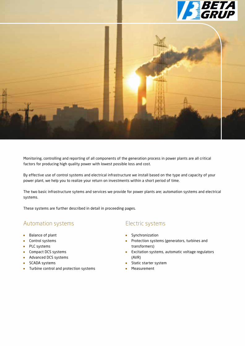
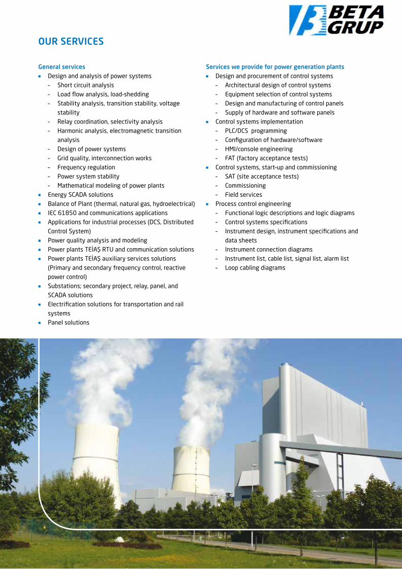
Monitoring, controlling and reporting of all components of the generation process in power plants are all critical
factors for producing high quality power with lowest possible loss and cost.
By effective use of control systems and electrical infrastructure we install based on the type and capacity of your
power plant, we help you to realize your return on investments within a short period of time.
The two basic infrastructure sytems and services we provide for power plants are; automation systems and electrical
systems.
These systems are further described in detail in proceeding pages.
Automation systems
n Balance of plantn Control systemsn PLC systemsn Compact DCS systemsn Advanced DCS systemsn SCADA systemsn Turbine control and protection systems
Electric systems
n Synchronizationn Protection systems (generators, turbines and
transformers)n Excitation systems, automatic voltage regulators
(AVR)n Static starter systemn Measurement

IEC
61
85
0
Mod
bus
Mod
uleb
us
PR
OFI
BU
S /
Foun
dati
on F
ield
bus
/ M
odul
ebus
PR
OFI
BU
S /
PR
OFI
NET
/ M
odul
ebus
/ D
evic
eNet
Process Instrumentation DevicesProcess ElectrificationPower Automation
Main System Servers
Field Network
Protection and Control LED
System Network Workstation
Wireless HART Gateway
AC800MController
Motor Controller
Variable Speed Control Drivers
Medium Voltage Switchboards
S900/IO
S800/IO
Wireless HART

Safety PLC and DCS Connections
Facility Network
Panel 800
AC800MHigh Integrity Controller
Fire and Gas
Closing
S800, S100...
Advant, MOD, Harmony...
AUTOMATION SYSTEMS INPOWER PLANTS
Contributions of automation systems for power plants
n Opportunity to access all control parameters from
any point in the systemn Managing and monitoring the entire system from a
single control platformn Rapid command issuingn Integration of electric infrastructure and automation
systemsn Prior determination and prevention of unexpected
faults and reduction of maintenance timen Secure data acquisition and fast data flow
Automation and control systems enable efficient and safe operation of power plants by minimizing the risks. Monitoring and reporting ensure the opportunity to access all control points from any given point in the system as well as flexibility, speed and minimized faults.
System architecture

Controller
Servers
Low Voltage Switchboards
Medium Voltage Switchgears
Power Transformer
Web HMI
IEC 61850
GIS
AIS
HV
Excitation Control
Power Distribution Process Electrification
BALANCE OF PLANT
Independent from the type of your power plant, our
experience and engineering know-how allows us to
provide ”Balance of Plant“ integration specific to your
installations and turn-key system integration.
Balance of Plant includes systems, components and
structures in a power plant other than the main
generation system and heat recovery systems (e.g. gas
turbines, steam turbines...). BOP aims to combine various
independent control systems on a single platform.
Integration of these systems in an optimum way, ability
to share data among systems and the flexibility
introduced by this system are important parameters
leading to the efficiency and productivity of a power
plant.

PROFINET Field Bus Network
Workstations
Control Network
Field Bus Structure
Instrumentation Devices
Valve
Low Voltage Products
Remote ConnectionsDriver
Proxy for Profibus and other busses
Process Electrification Process Control
Services we provide within the Balance of Plant packagen Modulation controln Sequence controln Boiler burning controln Feed water pump controln Boiler safety supervisionn Data acquisitionn Electrical system controln “Balance of Plant” equipment control
n Stack gas desulphurization controln Turbine controln Turbine supervision instrumentation devicesn Combined Cycle controln Emergency shutdownn Data transfer to ERP systemn Boiler optimizationn System efficiency map

BALANCE OF PLANT
MainSteamValves
Electricity
Water
Sewage
Site Facilitiesduring Construction
Main Fuel• Unloading• Storage• Preparation• Transfer
Startup Fuel• Unloading• Storage• Transfer
Fly Ash• Transfer• Storage• Loading
HP Feed Heating
Water Chemistry
CW Chemistry
AirEvacuation
Discharge
Ammonia• Unloading• Storage• Transfer
Sorbent• Unloading• Storage• Preparation• Transfer
Gypsum• Preparation• Transfer• Storage• Loading
Bottom Ash• Transfer• Storage
Silos& Mills
AuxiliaryBoierBoiler
Burner Pressure Firing Parts
Boier C&I
BOP / Plant C&I
FD Fan
SCR /De-NOx
ESP
FGD
Stack
PA Fan
Plant DCS & Interfaces
IDFan
LP Feed Heating
By pass
CPP
HP Pipework & Valves
HPT LPT
ST C&I

Turbine Auxiliaries
Building Services
Generator and Auxiliary
Turbine and Auxiliary
Boiler
BoPE
Environmental Control Systems
Main Plant Auxiliary Systems
HV Switchyard
Start up Diesel
Condenser
FireFighting
Sewage Plant
WastewaterTreatment
CoolingTower
PotableWater
Mobile Equipment
TechnicalBuildings • Boiler Building
• Turbine Building• Electrical Building• Auxiliary Technical Buildings
• Administration Building• Canteen / Social Building• Workshop• Warehouse• Gate House• Fence
NonTechnicalBuildings
HVAC
Lighting
Lightning
Communication / IT
Generator C&I / AVR / CTs / VTs
Electrical Systems
MV / LV / DC
Step up TransformerGenerator
Auxiliaries
By pass
GenLPT
Water Treatment
CW Mech Cleaning

CONTROL SYSTEMS
PLC Systems
PLC offers maximum speed and efficiency in production
processes and an ideal solution for a multitude of
automation needs; from simple to complex that require
high performance, low cost and flexibility. ABB‘s AC500
automation platform for PLC applications is capable of
meeting these ever increasing customer requirements.
With its scalable architecture, AC500 secures your
investment. Managing more than one field bus with a
single control system, user-friendly structure, easy
configuration and ample communication possibilities are
other significant advantages provided by AC500 PLC to
our customers.
Compact DCS Systems
Compact and scalable DCS systems -in addition to
providing powerful automation functions- present low
cost advantage for hardware and software. Ensuring
minimum engineering and maximum automation
facilities, ABB Freelance compact DCS systems have open
and modern system architecture. With its distributed
architecture installed at the field by controllers, it can
effectively reduce cabling costs. Freelance requires single
software for application engineering, commissioning and
fault finding and therefore can be fully integrated into
field bus management control system. Visual components
pre- engineered for operators are one of many
advantages to users.
With its ability to work on standard computer hardware, in
addition to control systems such as DCS, PLC as well as
capability to convert all control parameters into visual
control tools, SCADA software makes it possible to expand
the system to meet changes in future requirements.
Based on open protocol, SCADA is hardware and
manufacturer independent and therefore capable of
expanding to meet future requirements. It contributes to
facilitating reporting and detailed analysis, minimizing
faults, evaluation and improvement on energy efficiency
and system performance.

Advanced DCS Systems
Advanced DCS systems are used for accessing multiple
applications and multiple data from any workstation
located at any point at the power plant. ABB System
800xA advanced DCS systems increases productivity as
well as decreasing risks and costs.
Integrated engineering infrastructure of the System
800xA minimizes complexities from planning to
configuration and from library management to
commissioning, and offers savings by supporting
lifespan of automation projects. Compliant with IEC
61508 and IEC61511, System 800xA provides security
for the entire system and minimizes the risk ratio.
Powerful reporting feature enables reporting by
processing any process related information. The
advanced planning feature of System 800xA allows a
multitude of different requirements for increasing
production, to be identified beforehand. Also,
continuously monitoring the state of equipment in a
power plant with System 800xA allows for preventive
maintenance which is important to achieve investment
optimization.
Advantages offered by System 800xA in energy productionn A platform that can meet future process and
electrical systems requirementsn Capable of meeting IEC 61850 requirementsn User-friendly user interfacen Ability to access from any point outside the facilityn Quick fault analysis capabilityn Outstanding engineering skills and qualityn Low budget operation and managementn Simple system architecturen Unique technology and integration with existing
systems
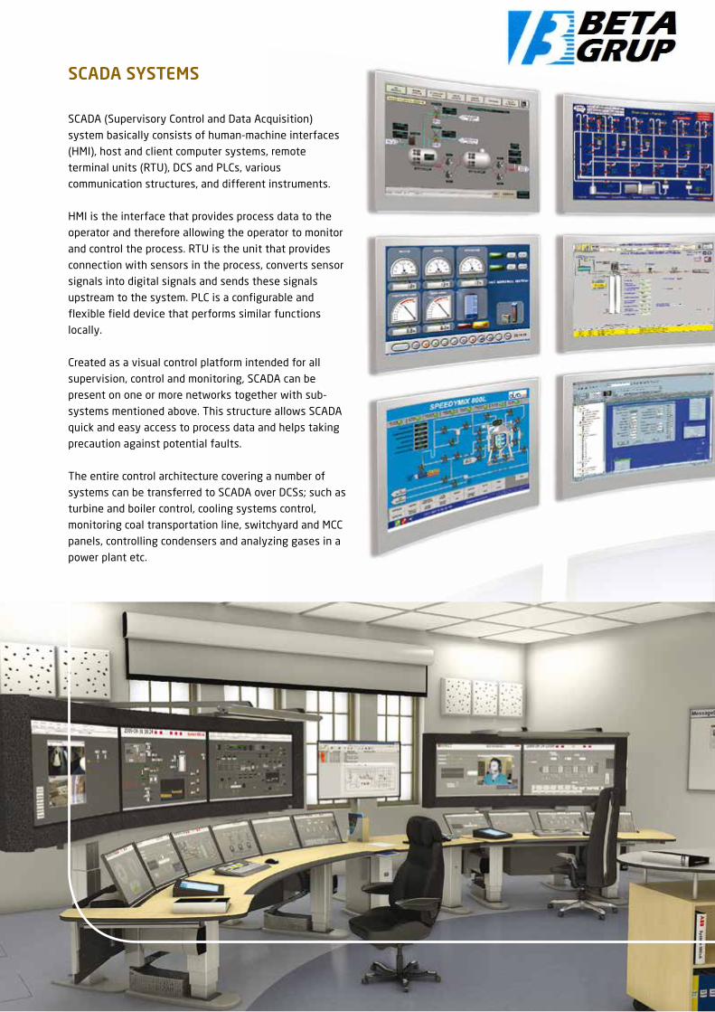
SCADA SYSTEMS
SCADA (Supervisory Control and Data Acquisition)
system basically consists of human-machine interfaces
(HMI), host and client computer systems, remote
terminal units (RTU), DCS and PLCs, various
communication structures, and different instruments.
HMI is the interface that provides process data to the
operator and therefore allowing the operator to monitor
and control the process. RTU is the unit that provides
connection with sensors in the process, converts sensor
signals into digital signals and sends these signals
upstream to the system. PLC is a configurable and
flexible field device that performs similar functions
locally.
Created as a visual control platform intended for all
supervision, control and monitoring, SCADA can be
present on one or more networks together with sub-
systems mentioned above. This structure allows SCADA
quick and easy access to process data and helps taking
precaution against potential faults.
The entire control architecture covering a number of
systems can be transferred to SCADA over DCSs; such as
turbine and boiler control, cooling systems control,
monitoring coal transportation line, switchyard and MCC
panels, controlling condensers and analyzing gases in a
power plant etc.

In addition to control functions, SCADA offers many
facilities such as monitoring events and alarms,
examining and reporting information retrospectively,
providing information to remote operators via GSM
networks. Production report drafts required by electric
utilities companies can be prepared beforehand with
reporting function and automatically created at desired
intervals (daily, weekly, monthly, etc.). Also, “predictive
maintenance” can be made by monitoring operation
times and alarms of actuators such as breakers, engines,
pumps, valves located in the field. In this way, faults
which may occur can be estimated, and down times may
be shortened. With Thin Clients or Web Clients, state of
the system can also be monitored from any remote point
outside of the plant.

TURBINE CONTROL AND PROTECTION SYSTEMS
Turbines are at the heart of the electric generation
process and play an active role for converting
mechanical energy into electric energy. Turbines can be
classified as steam, gas, hydro and wind turbines
according to the energy resources they require.
Parameters that are controlled in a turbine control
system may be adapted based on the type of energy
resource. As an example, for the purpose of continuous
and quality energy production in thermal power plants,
it is necessary to control and monitor different
parameters such as water amount and water circulation,
control of feed-water, boiler water temparature, amount
of fuel, pressure, igniter control system, water cooling
system, all the way from burning fuel stage to obtaining
steam and turning turbines.
Turbines can be controlled with PLCs or dedicated
control devices. These systems perform critical closed
closed-loop algorithms such as speed and load control.
Apart from general SCADA interface for controlling and
monitoring, alarm and reporting functions can be
provided with a local and dedicated interface. Data
obtained from the site can be transferred into
SCADA system.
Benefitsn Low lifespan costn Optimized operationn Excellent reliabilityn Increased turbine lifespan via sensitive controlsn Short commissioning timen Decreases in fault costs and repair timesn Fully automated operation eliminating operator
errorsn Quick access to information
For Turbine Control Systems, We use...

Turbine protection systems and valve positioning
products are additional components supplementing the
system. Speed, the most critical parameter for rotating
parts, is continuously monitored. Protection systems
are connected to other field devices such as speed
measurement devices and servo valves in turbines.
These provide over speed protection and valve
positioning controls independent from main control.
Turbines are protected and their lifespan is extended
by monitoring many critical parameters such as speed,
oil pressure, temperature, etc. As a result, a quicker,
more flexible, functionally enriched turbine control
system is obtained.

ELECTRIC SYSTEMS IN POWER PLANTS
Facilities need qualified and trained human power, large investment expenses and technologies in order to meet the increasing demand for energy. At this point, automation and smart electric infrastructure is now an indispensable characteristics.
Kontrolmatik installs turn key excitation systems,
generator protection systems, synchronization systems,
energy invoicing/automated meter reading systems.
Furthermore, as additional services we implement
various applications such as primary and secondary
frequency control systems, reactive power control
systems.
Main applications n Synchronizationn Protection systems
– Generator
– Turbine
– Transformern Excitation systems, automatic voltage regulators
(AVR)n Static starter systemn Measurementn Network connection and power qualityn MCC panel systems

Generator synchronization systems are devices for
providing network and generator safety and security that
are generally used in power generation facilities,
industrial facilities such as cogeneration facilities,
marine industry, hospitals, shopping centers and hıtels.
The main purpose of using generators is to minimize
power interruption time and keep continuos power where
connection is available.
The main function of generator synchronization systems
is to transfer energy from the network to the generator
or in reverse case to ensure transition of supplied energy
with synchronized amplitude, phase angle and frequency.
Otherwise overloading can occur at the network or
generator, irregularities may occur at the network,
breakers may open or generators may be damaged.
The main purpose of performing the synchronization
process is to automatically or manually ensure network
and generator security.
During synchronization process, in case a fault occurs on
one of the serially connected channels in a ”dual
channel“ application, the other channel is also blocked.
This configuration increases security. In applications
with “back-up”, in case of any fault anyone of the parallel
connected devices, the other one overtakes the function
and ensure its continuous operation.
SYNCHROTACT product range from ABB is a device
preventing switching in asynchronous mode where there
is significant difference between voltage and phase
angles. Prior to connecting these systems,
SYNCHROTACT brings voltage and speed of generator to
automatically adjusted tolerance interval taking into
account voltage, frequency, phase angle and breaker
switching time. Digital dual channel and redundant
synchronization systems provide high level of reliability.
SYNCHRONIZATION
PROTECTION SYSTEMS
In a power plant, generators and transformers are units
that are the most likely to have faults and thus they
should be protected in the best manner. Generator
protection includes transformers and auxiliary
transformers in addition the generator itself. In principle
the generator protection includes determining faults and
irregular states within the shortest possible time and
minimizing damages that may occur.
Regardless of the generator type, we provide the most
efficient electric infrastructure as well as secure and
economic systems integration by establishing the criteria
in which a generator can work securely and efficiently.
We use ABB protection units which have modular
hardware, have flexible structure, and utilize
microprocessor based technology. Protection functions
can be selected taking suitable redundancy into account.
This enables reliable, secure and economic functioning of
the generators.
Relion product range designed by ABB for generator
protection provides wide range of products for
protection, control, measurement, and supervision of
generators, transformers, and power lines. Relion product
range meets the requirements of IEC 61850 standard.
The 24 analog inputs of devices that we use ensures
main and redundant protection with a single product.
Alternatively, protection of additional elements such as
transformers can be included to the protection scope of
generators. In addition to cost saving advantage, using
less products reduces the amount of installation and
maintenance work.
These devices offer injection based 100% protection of
stator and earthing faults and 3rd degree harmonic
based 100% protection of stator and earthing faults.
Secure operation is ensured even in low loads.

EXCITATION SYSTEMS
Excitation systems have significant effects on dynamic
performance of generators. Quality of generator voltage
and reactive power, as well as quality of energy
distributed to all electric end users are all determined by
excitation systems.
There are various excitation systems:n Brushless excitation systemsn Rotary excitation machinery and automatic voltage
regulator (AVR)n Static excitation systems (SES) feeding rotors
directly over brushes with thyristor bridge.
The main function of excitation system is to provide
variable DC current having short-period excess load
capacity, control output voltage having proper accuracy,
guarantee stable operation, communicate with power
plant control system and ensure operation of generator
within operating limits.
In systems installed by Kontrolmatik, we use ABB‘s
UNITROL series microprocessor based voltage regulators
with rotary excitation and static excitation systems for
controlling of any type of synchronous machinery (motor
and generator).
UNITROL® includes automatic voltage regulators (AVRs)
and static excitation systems (SESs) that can be used in
any size synchronous generator and motor.
Advantagesn Customer-oriented standardizationn System solutions tailored to customer needsn Compliant with ISO 9001/ISO 14001 quality
management systemsn Worldwide commissioning and maintenance servicesn Quick commissioning and maintenance time with
user friendly software tool

STATIC STARTER SYSTEM (FOR GAS TURBINES)
MEASUREMENT
In power plants, measurement equipment with high level
of sensitivity determines how much energy is supplied
to customers from the production field. Measured values
are current, voltage, active and reactive power. These
values are used for pricing energy consumed and
obtaining statistical data.
Gas turbines need boosting for reaching ignition
point (60% of nominal speed). For gas turbines over
40MW, this can be achieved with two different methods.
n Pony motor with gears on main shaftn Static frequency converter (SFC) that directly
connects to generator terminals and enables
operation of the generator as an motor at the
beginning of the phase.
Static starter enables acceleration of the generator
smoothly without any vibration or voltage drop. Also, it
helps deceleration of the generator smoothly. A single
SFC can operate several generators connected in-line.

NETWORK CONNECTION AND POWER QUALITY
The reliability and quality of energy being produced is
indeed very important. Simply put, quality of energy is
protection of rated value of amplitude and frequency of
voltage and sinusoidal character of the wave in any
point on the network. Since electric power needs to be
continuous and can not be stored on the consumer side,
it is not possible to provide any assurance of quality and
inspection before use. Therefore, the energy generated
should be reliable and in high quality. Unfortunately,
power generated in high quality from the generators
cannot be transmitted to the consumer keeping its initial
quality. After generation phase, connection of electric
power to the grid also should also be performed in a way
to keep maximum quality.
Primary frequency control
Primary frequency control (PFK) service enables bringing
system frequency to a new balance point by means of
automatically increasing or decreasing active power
output of the unit via speed governor, in reaction to
decrease or increase in system frequency. In other
words, when system frequency decreases below 50 Hz,
active power production is increased via speed governor
located in the turbines and frequency is stopped at
a value below 50 Hz. (e.g. 49.70 Hz). Bringing the
frequency stopped at this value to its former value (50
Hz) will be possible with secondary frequency control.
Power plants have redundancy for such purposes.
Primary Frequency Control Performance TestTechnical procedure regarding primary frequency control
performance tests is explained in Annex 4.A of the
Electricity Market Grid Regulations. Prior to starting
performance tests, it is expected from the employees of
production facility to submit simplified block diagram of
control systems of the unit and operation between
turbine speed governor and control system for the
purpose of showing function of primary frequency
control. During primary frequency control performance
tests, the following values are measured and recorded
along with other values deemed necessary by the
testing team: n Active Power Output (MW)n Network Frequencyn Simulated Frequencyn Valve Positionsn Steam Pressure (TEPP)n Steam Temperature (TEPP)
During primary frequency control performance tests,
sampling rate of measurement made for each value
should be 10 data per seconds.
Primary frequency control performance tests consist of
three stages:
1- Primary Frequency Control Reserve Test
2- Primary Frequency Control Sensitivity Test
3- Primary Frequency Control 24 Hours Verification Test
Secondary frequency control
Secondary frequency control service is needed when the
system frequency increases or decreases in order to
bring to nominal value and to the programmed value for
exchange of total electric power with interconnected
electric grids.
Secondary Frequency Control Performance TestSecondary frequency control performance tests consist
of two stages: These stages are pre-qualification test of
secondary frequency control to be performed in
production units, and secondary frequency control
performance test to be performed over Automatic
Generation Control (AGC) system in National Load
Dispatch Center. AGC System/Interface functions will be
checked in generation unit that will participate in
secondary control according to the setting values sent
by Automatic Generation Control (AGC) program located
in National Load Dispatch Center.
It is checked if the “PD Validity” signal sent periodically
by AGC program to generation unit via SCADA System is
being correctly used and in case such signal is not
received for a certain timeout period (60 seconds) a
LRPD alarm is generated in the power plant; and
Automatic Generation Control System/Interface switches
from REMOTE to LOCAL and switching back to REMOTE
position can only be possible by operator intervention
after receiving “PD Validity” signal.
The following items are checked if they are displayed in
Automatic Generation Control System/Human Machine
Interface installed in generation unit:n AGC control block diagramn Operation mode of AGC systemn Setting value and distribution to unitsn Local setting values (Operator intervention is
possible)n Secondary frequency control limits based on unit
(Operator intervention is possible)n Maximum and minimum capacity values of secondary
frequency control of generation unit (MAXC and MINC)
- Generation unit secondary frequency control bandn “PD Validity” signal staten Alarms regarding AGC System/Interfacen Total primary reserven Primary frequency control participation state (PFCO)
signals for unitsn Load ramp up/down speeds of unitsn Speed governor droop setting - Total power plant
generationn Control error (difference between setting value and
power plant generation)

Reactive power control
Reactive power is required for operation of all devices
that need the effect of magnetic field. Reactive energy
is needed for all devices (e.g. electric motors etc.)
particularly for transformers operating with magnetic
field. However, transferring reactive energy to energy
transmission lines by producing in generation facilities
causes limitation on active power that a line can carry,
and consequently decrease on the line capacity due to
the reason that reactive energy occupies space just as
active energy on transmission lines do. Consequently,
reactive power factor should be kept at levels
determined by regulations.
Reactive Power Control and Synchronous Condenser Performance TestOperation in over-excitation: Means reactive power is
delivered to the system by the generator.
Operation in under-excitation: Means reactive power is
taken-up from the system by the generator.
In addition to records captured in power plants during
generation unit secondary frequency control tests, the
following values will be recorded from SCADA system by
TEİAŞ National Load Dispatch Center:
n Setting values sent by National Load Dispatch Centern System frequency valuen Active power generation of power plant/block/unitn Active power generation of units (when necessary)
Maximum reaction time should be 30 seconds in order to
start changing power output of generation unit which
provides secondary frequency control service, and it
should reach required generation level according to the
loading speed determined as result of tests. Loading
speed of units providing secondary frequency control
service should be as follows depending on the fuel type:
n At least 6% of nominal power per minute for diesel
oil, fuel oil, and natural gas generation facilitiesn Between 1.5% and 2.5% of nominal power for
hydroelectric generation facilities with reservoirn Between 2% and 4% of nominal power for generation
facilities using hard coal as a fuel
n Between 1% and 2% of nominal power for generation
facilities using lignite as a fuel

Power quality analysis
Electricity produced at the plant sustains losses and
quality is compromised until delivered to the consumer.
Irregular use of transformers and cables from generation
facilities to the consumer as well as use of illegal
connections to the network inevitably affect quality and
dependability. Therefore, it is very important to ensure
top-quality electricity distributed from the power plants.
Quality of power in simple terms is protection of rated
value of amplitude and frequency of voltage and
sinusoidal character of wave in any point on the
network. Fluctuations in voltage amplitude, power
interruptions, changes like pulses, harmonics, frequency
changes, flicker, three-phase imbalances are the primary
known reasons for power quality losses.
Loads that take non-sinusoidal currents from the
network cause severe harmonic pollution in transmission
and distribution systems and creates line voltage drops
causing disturbance of voltage waveform. Potentially
problematic points should be prevented during grid
design or points presenting danger should be identified
by making risk estimations.
In order to create solutions to increase the quality of
energy generated, the reasons for lack of quality should
be identified, the occurance times should be determined
and this data should be used to create classifications. By
measuring power quality, different parameters such as
voltage and current changes can be recorded and
necessary precautions can be prepared based on the
results of such measurements; consistency of the
system can be ensured, and great commercial benefits
can be obtained by preventing non-scheduled power
cuts. Continuously monitoring the network enables
obtaining necessary data required for statistical analysis
of problems seen in power systems. This will allow
determining the precautions for future.
Compliant standardsn IEC 61000-4-30: Power quality measurement
methods, Class An IEC EN 61000-4-7: Harmonic measurement manualn IEC EN 61000-4-15: Flickermetern EN 50160: Voltage Characteristics of Electricity
Supplied by Public Distribution Systems
Features of the softwaren FFT analysisn Vectorscope, oscilloscopen Power and energy monitoringn Voltage monitoring with EN 50160 Flickermetern Symmetrical component analyzer for 3 phase
systemsn Power network impedance analyzer-Semi periodical
RMS monitoringn Transitive log device and fault log devicen Voltage telegram and alarms-Digital inputs

MCC panels are panel systems where engine main
feeding units and control devices are located.
Control devices such as PLC and DCS and other devices
required for SCADA and communications infrastructure
are found in control section of the MCC panel.
Panels are important components of the system and are
supplementary in projects we implement. For all systems
that we install, Kontrolmatik can produce type-tested
distribution panels including form 4-B, MCC Panels
(Motor Control Panels) and Motor Driver Panels up to 400
KW within our own capacities.
In accordance with IEC 60439-1 standard, we separate
functional sections from each other within the panels
with form applied LV Distribution and MCC panels, in
order to increase the safety of personnel and facilities.
For custom applications, we can produce panel
applications with IP66 protection class as well as UL50
certified panel applications in accordance with American
standards. We use RAL7035 and RAL7032 colors as
standard.
We use custom-designed bus systems for power
distribution systems and especially MCC panels.
MCC PANEL SOLUTIONS


BETA Operation and Technique Service Inc.
HEAD OFFICEAdress : İnönü Caddesi Sümko Sitesi
Sümer Sokak C6 Blok No: 3F-634736 Kozyatağı / İstanbul / TURKEY
Tel : +90 216 416 64 17 Fax : +90 216 416 64 21
BETA Operation and Technique Service Inc.
www.betagrup.com