best practice for energy efficient cleanrooms tengfang xu …best practice for energy efficient...
TRANSCRIPT
Best Practice for Energy Efficient Cleanrooms
Tengfang Xu
2005
Contents
HVAC WATER SYSTEMS ............................................................................................... 2
Variable speed pumping ............................................................................................................... 2
Summary ..................................................................................................................................... 2
Principles ..................................................................................................................................... 3
Best practice approaches ............................................................................................................. 4
Case studies ................................................................................................................................. 4
Related best practice .................................................................................................................... 6
References ................................................................................................................................... 7
Resources .................................................................................................................................... 7

HVAC Water Systems Variable speed pumping
Summary
Cleanroom energy benchmarking data shows that chiller plant designs and operating efficiencies varied significantly from cleanroom to cleanroom. While system optimization is critical to the overall energy efficiency of chiller plants, the operating efficiency of chilled water and condenser pumps, along with chiller efficiency and cooling tower efficiency, is a major factor in the overall system efficiency. The design and operating efficiency of water pumps directly affects energy use for such facilities.
Figure 1 shows benchmarked HVAC energy end use in a semiconductor cleanroom facility. In this case, the water pumps collectively accounted for 17% of the total energy use. Figure 2 shows the electric power demand of the components in a chiller plant system. Pumps accounted for 18% of the total power demand for the whole chiller plant. It is important to design, select, operate, and control water-pumping systems to achieve high efficiency and to lower life-cycle costs for cleanrooms and their adjacent spaces.
Figure 1 Benchmarked HVAC energy end use in a semiconductor cleanroom facility
Chillers39%
Cooling Towers
7%
Pumps17%
MUAH + RCU Fans9%
Hot Water + Steam25%
Exhaust Fans3%

Figure 2 Benchmarked water pump power demand in a chiller plant in a semiconductor cleanroom
Principles
The overall energy efficiency of a water system is affected by the efficiency of individual components, in addition to system sizing, load, and system resistance (pressure drop). For a typical cleanroom facility, major components include hot water pumps, chillers, primary loop chilled water pumps, secondary loop chilled water pumps, condenser water pumps, and cooling tower fans. While the energy efficiency of individual components influences the overall chilled water plant efficiency, the design, control, and operation of the water systems largely affects the system and plant efficiency. The ability to lower water flowrate with a variable-speed-drive (VSD) motor while maintaining desirable water temperatures can significantly improve the energy efficiency of water pumps. Implementing variable-speed drives for the water pumps may significantly improve the design, control, and operating efficiency of water systems.
Chiller Power (kW)62%
Chilled Water Pumps Power (kW)
13%
Cooling Tower Power (kW)
20%
Condenser Water Pumps Power (kW)
5%

Figure 3 Water pumps
Best practice approaches
It’s common that water systems are often designed and operated at part-load conditions. Best practice approaches include optimizing design, operation and control of the water systems. Variable-speed-drive pumps should be used to control and balance water flows to minimize the need for throttling design. For example, they can be used to avoid booster pumps and close bypasses, which are common in practice but are not energy efficient. Providing variable-speed-drive pumping can improve energy efficiency of water systems in such operation while achieving cooling (and sometimes heating) required for cleanrooms. At the same time, right sizing pumps and their VSDs may improve flow controls and optimize initial cost as well as operating costs.
Case studies
In one case study, a hot water system (Figure 4) included two 60 hp circulating pumps (running at constant speeds) and was designed for a temperature drop of 20°F with 1,570 gpm (equivalent to 15 million Btu). The hot water was sent to the heating coils throughout the building. Most coils operated with two-way valves while some used three-way valves. The power usage for a 24-hour period where flow and temperatures were recorded was measured as 1.7 million Btu, which represented 11% of the design load. One of the pumps had a low quality VSD that was non-operational. Due to the current three-way valve arrangement and constant speed pump operation, the temperature difference was extremely low and the flow remained close to design.

Figure 4 Hot Water Pumps
A more efficient operation of this system would be to keep the temperature difference close to design and vary the flow based on the load using a VSD. For example, water flow could be reduced from the design of 1,570 gpm to 350 gpm if only a 10 F° temperature difference is maintained. Should the new flow be significantly below the design water flow, a smaller motor would be required to allow the new pump to operate efficiently; at the same time, a smaller motor would also reduce the cost of the VSD.
Based upon other case studies, Figure 5 shows the variation in energy efficiency of water pumps in chilled water plants for a group of cleanroom facilities. The best practice in overall water pump efficiency is shown in the following:
• Primary Chilled Water Pumps Efficiency: 0.047 kW/ton;
• Secondary Chilled Water Pumps Efficiency: 0.019 kW/ton;
• Condenser Water Pumps Efficiency: 0.089 kW/ton.
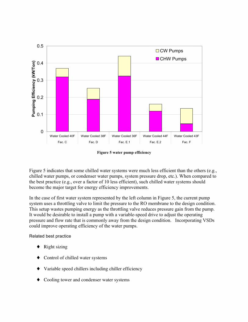
Figure 5 water pump efficiency
Figure 5 indicates that some chilled water systems were much less efficient than the others (e.g., chilled water pumps, or condenser water pumps, system pressure drop, etc.). When compared to the best practice (e.g., over a factor of 10 less efficient), such chilled water systems should become the major target for energy efficiency improvements.
In the case of first water system represented by the left column in Figure 5, the current pump system uses a throttling valve to limit the pressure to the RO membrane to the design condition. This setup wastes pumping energy as the throttling valve reduces pressure gain from the pump. It would be desirable to install a pump with a variable-speed drive to adjust the operating pressure and flow rate that is commonly away from the design condition. Incorporating VSDs could improve operating efficiency of the water pumps.
Related best practice
♦ Right sizing
♦ Control of chilled water systems
♦ Variable speed chillers including chiller efficiency
♦ Cooling tower and condenser water systems
0
0.1
0.2
0.3
0.4
0.5
Water Cooled 40F Water Cooled 38F Water Cooled 36F Water Cooled 44F Water Cooled 43F
Fac. C Fac. D Fac. E.1 Fac. E.2 Fac. F
Pum
ping
Effi
cien
cy (k
W/T
on)
CW Pumps
CHW Pumps

♦ Free cooling
♦ Dual temperature cooling loops
References
1) http://hightech.lbl.gov
Resources
• Energy Design Resources, Design Brief: Chiller Plant Efficiency, http://www.energydesignresources.com/resource/24/
• ASHRAE handbook – HVAC systems and equipments.
• PG&E’s CoolTools, http://www.hvacexchange.com/cooltools/