best practice for design of maritime structures
TRANSCRIPT

7/24/2019 Best Practice for Design of Maritime Structures
http://slidepdf.com/reader/full/best-practice-for-design-of-maritime-structures 1/25
1
BEST PRACTICE FORBEST PRACTICE FOR
DESIGN OF MARITIMEDESIGN OF MARITIME
STRUCTURESSTRUCTURES
ANDREW PATTERSON ANDREW PATTERSON
PATTERSON BRITTON & PARTNERSPATTERSON BRITTON & PARTNERS,,CONSULTING ENGINEERSCONSULTING ENGINEERS
INTRODUCTIONINTRODUCTION
Consider concrete, steel, and timber, butConsider concrete, steel, and timber, butfocus on concretefocus on concrete..
Concrete is where most of the trouble lies.Concrete is where most of the trouble lies.
Steel is straightforward and we understandSteel is straightforward and we understandthe design and maintenance issues.the design and maintenance issues.
Timber, unfortunately is being legislated out Timber, unfortunately is being legislated outof fashion (incorrectly).of fashion (incorrectly).
Concrete, we don’t seem to understand; andConcrete, we don’t seem to understand; andthings are getting worse.things are getting worse.
7/24/2019 Best Practice for Design of Maritime Structures
http://slidepdf.com/reader/full/best-practice-for-design-of-maritime-structures 2/25
2
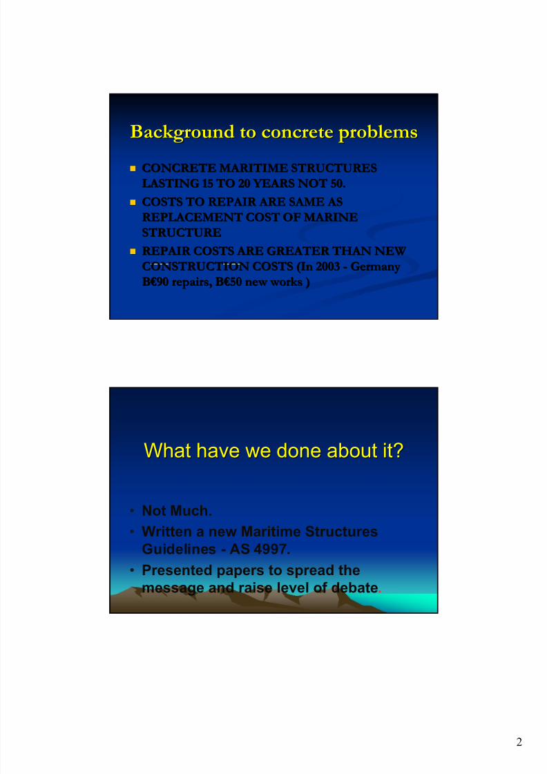
Background to concrete problemsBackground to concrete problems CONCRETE MARITIME STRUCTURESCONCRETE MARITIME STRUCTURES
LASTING 15 TO 20 YEARS NOT 50.LASTING 15 TO 20 YEARS NOT 50.
COSTS TO REPAIR ARE SAME ASCOSTS TO REPAIR ARE SAME AS
REPLACEMENT COST OF MARINEREPLACEMENT COST OF MARINE
STRUCTURESTRUCTURE
REPAIR COSTS ARE GREATER THAN NEWREPAIR COSTS ARE GREATER THAN NEW
CONSTRUCTION COSTS (In 2003CONSTRUCTION COSTS (In 2003 -- GermanyGermanyBB €90 €90 repairs, Brepairs, B €50 €50 new works )new works )
What have we done about it?What have we done about it?
• Not Much.
• Written a new Maritime Structures
Guidelines - AS 4997.
• Presented papers to spread the
message and raise level of debate.

7/24/2019 Best Practice for Design of Maritime Structures
http://slidepdf.com/reader/full/best-practice-for-design-of-maritime-structures 3/25
3
RECENT HISTORY RECENT HISTORY Newer concrete structures have corrosionNewer concrete structures have corrosion
problems problems
1.1. Jetty at Eden failed after SEVEN years. Jetty at Eden failed after SEVEN years.
2.2. RTA bridge piers lasting only about 20 yearsRTA bridge piers lasting only about 20 years
3.3. Many R.C. maritime structures require majorMany R.C. maritime structures require majorrepairs after 20years (Sydney Opera House,repairs after 20years (Sydney Opera House,Kernell Oil jetty, MSB Bulk Liquids Berth)Kernell Oil jetty, MSB Bulk Liquids Berth)
4.4. Prestressed beams failing after 15 years, inclPrestressed beams failing after 15 years, inclsudden collapse. (BLB, Rockdale Council,sudden collapse. (BLB, Rockdale Council,Brighton Le Sands, Cambodia)Brighton Le Sands, Cambodia)
This wharf was only This wharf was only sevenseven years old: years old:
7/24/2019 Best Practice for Design of Maritime Structures
http://slidepdf.com/reader/full/best-practice-for-design-of-maritime-structures 4/25
4
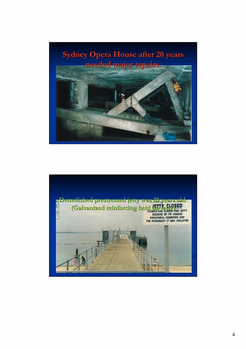
Sydney Opera House after 20 yearsSydney Opera House after 20 years
needed major repairs.needed major repairs.
Demolished prestressed jetty was 20 years old.Demolished prestressed jetty was 20 years old.
(Galvanized reinforcing held up jetty)(Galvanized reinforcing held up jetty)
7/24/2019 Best Practice for Design of Maritime Structures
http://slidepdf.com/reader/full/best-practice-for-design-of-maritime-structures 5/25
5
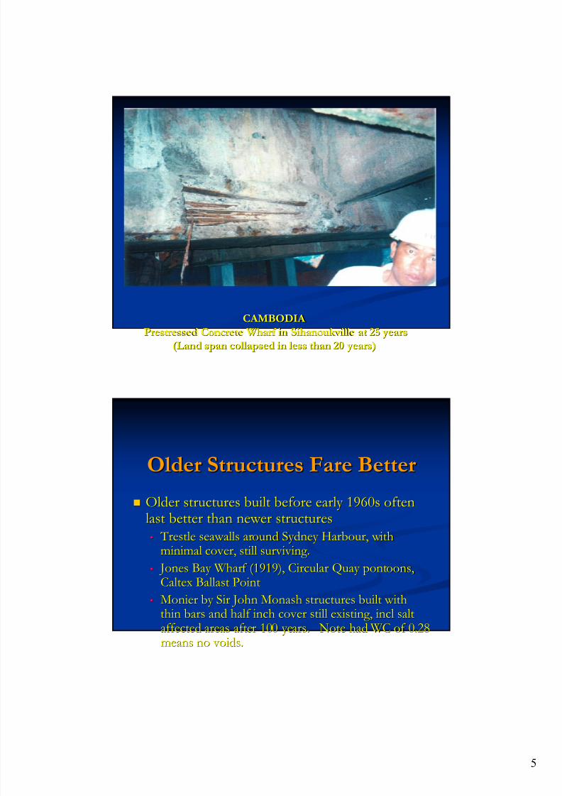
CAMBODIA CAMBODIA
Prestressed Concrete Wharf inPrestressed Concrete Wharf in SihanoukvilleSihanoukville at 25 yearsat 25 years
(Land span collapsed in less than 20 years)(Land span collapsed in less than 20 years)
Older Structures Fare BetterOlder Structures Fare Better
Older structures built before early 1960s oftenOlder structures built before early 1960s oftenlast better than newer structureslast better than newer structures
•• Trestle seawalls around Sydney Harbour, with Trestle seawalls around Sydney Harbour, with
minimal cover, still surviving.minimal cover, still surviving.
•• Jones Bay Wharf (1919), Circular Quay pontoons, Jones Bay Wharf (1919), Circular Quay pontoons,Caltex Ballast PointCaltex Ballast Point
•• Monier by Sir John Monash structures built withMonier by Sir John Monash structures built withthin bars and half inch cover still existing, incl saltthin bars and half inch cover still existing, incl saltaffected areas after 100 years. Note had WC of 0.28affected areas after 100 years. Note had WC of 0.28means no voids.means no voids.
7/24/2019 Best Practice for Design of Maritime Structures
http://slidepdf.com/reader/full/best-practice-for-design-of-maritime-structures 6/25
6
What has changed? What has changed? Tri Tri--calcium Aluminate Ccalcium Aluminate C33 A A
•• C3a prevented steel corrosion by bonding to ClC3a prevented steel corrosion by bonding to Cl--
•• CC33 A slowed hydration and strength gain, less cracks A slowed hydration and strength gain, less cracks
•• Trouble was Trouble was -- Too slow for building industry Too slow for building industry
•• Has been reduced fromHas been reduced from 1212--15%15% toto 4%4%
•• No change to cements, as maritime structures too smallNo change to cements, as maritime structures too smalla marketa market
Cement grindCement grind .. Now have finer cements,Now have finer cements,faster hydration , more heat and shrinkage, microfaster hydration , more heat and shrinkage, micro--
cracking.cracking.
Lesson 1.Lesson 1.
CONCRETE IS ACONCRETE IS A SPONGESPONGE !! Cement content of 420 kg, and W/C ratio ofCement content of 420 kg, and W/C ratio of
0.450.45 -- 0.19 cu m of water0.19 cu m of water
Volume of water in hydration = 26% x 420kg Volume of water in hydration = 26% x 420kg
= 0.11 cu m of water= 0.11 cu m of water Therefore volume of voids (ie water in Therefore volume of voids (ie water in
capillaries) is 0.08 cu mcapillaries) is 0.08 cu m -- 8% by volume of8% by volume of voids. voids.
When designing maritime structures, think When designing maritime structures, thinkof the structure as being a sponge withof the structure as being a sponge with 8%8%to 10 % voidsto 10 % voids.. Has been measured atHas been measured at 20%20%
7/24/2019 Best Practice for Design of Maritime Structures
http://slidepdf.com/reader/full/best-practice-for-design-of-maritime-structures 7/25
7
SOME DESIGN OPTIONSSOME DESIGN OPTIONS
1. Chemical admixtures for chloride1. Chemical admixtures for chloride
absorption or corrosion inhibitorsabsorption or corrosion inhibitors
2. Pore blockers as admixtures or applied to2. Pore blockers as admixtures or applied to
hardened concretehardened concrete
3. Protection of steel surface (epoxy, galv)3. Protection of steel surface (epoxy, galv)
4. Non corrosive reinforcing 4. Non corrosive reinforcing
1. CHEMICAL1. CHEMICAL
ADMIXTURES ADMIXTURES Chloride bindersChloride binders
Anodic inhibitors Anodic inhibitors
Cathodic inhibitorsCathodic inhibitors
Electrolytic InhibitorsElectrolytic Inhibitors
DISADVANTAGESDISADVANTAGES
Most of chemical is wasted in core;Most of chemical is wasted in core;
Changes properties of wet concrete;Changes properties of wet concrete;
7/24/2019 Best Practice for Design of Maritime Structures
http://slidepdf.com/reader/full/best-practice-for-design-of-maritime-structures 8/25
8
2. PORE BLOCKERS2. PORE BLOCKERS
Organic (Caltite, 3CC)Organic (Caltite, 3CC) -- Additive Additive
Inorganic (Xypex)Inorganic (Xypex) -- Additive Additive
Silanes, Siloxanes, AquronSilanes, Siloxanes, Aquron
DISADVANTAGESDISADVANTAGES
Additives can modify concrete Additives can modify concrete Questions of long term stabilityQuestions of long term stability
Silanes cannot be used on wet concreteSilanes cannot be used on wet concrete
3. PROTECT STEEL FROM3. PROTECT STEEL FROM
CORROSIONCORROSION
Epoxy coated steelEpoxy coated steel – – not used innot used in Aust Aust..
Galvanised steelGalvanised steel -- beneficialbeneficial
Zinc AnodesZinc Anodes – – new developmentnew development
ICCPICCP (Impressed Current Cathodic Protection).(Impressed Current Cathodic Protection). PortPort Authorities only. Authorities only.
LICCP (Low Level Impressed Current CathodicLICCP (Low Level Impressed Current CathodicProtection)Protection) – – developing developing
Penetrating corrosion inhibitors.Penetrating corrosion inhibitors. NewNewdevelopmentdevelopment
7/24/2019 Best Practice for Design of Maritime Structures
http://slidepdf.com/reader/full/best-practice-for-design-of-maritime-structures 9/25
9
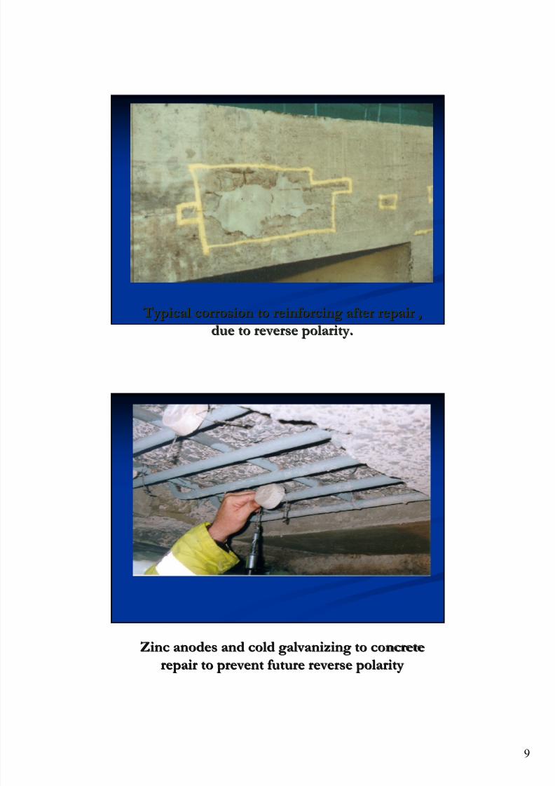
Typical corrosion to reinforcing after repair , Typical corrosion to reinforcing after repair ,
due to reverse polarity.due to reverse polarity.
Zinc anodes and cold galvanizing to concreteZinc anodes and cold galvanizing to concrete
repair to prevent future reverse polarityrepair to prevent future reverse polarity
7/24/2019 Best Practice for Design of Maritime Structures
http://slidepdf.com/reader/full/best-practice-for-design-of-maritime-structures 10/25
10
DESIGNS USING NONDESIGNS USING NON
CORROSIVE REINFORCINGCORROSIVE REINFORCING Stainless steel reinforcingStainless steel reinforcing – – special deformedspecial deformed
Grade 316L and Duplex 2205Grade 316L and Duplex 2205
Expensive, butExpensive, but goodgood long term answerlong term answer
Plastic filament (HDPE)Plastic filament (HDPE)
Not suitable for spans (“E” too soft)Not suitable for spans (“E” too soft)
CarbonCarbon fibrefibre
Very expensive Very expensive – – used for repairsused for repairs
RULES FOR CONCRETE DESIGNRULES FOR CONCRETE DESIGN
1. Avoid reinforcement.1. Avoid reinforcement. Use mass concrete. LightUse mass concrete. Light
stainless steel bars to retain segments.stainless steel bars to retain segments.
2. Avoid thin sections in splash/immersion zone.2. Avoid thin sections in splash/immersion zone.
If needed, then use SS reinforcing.If needed, then use SS reinforcing.
3. Avoid thin section generally.3. Avoid thin section generally. Use thick flat slabsUse thick flat slabs
rather than thin slabs and beams.rather than thin slabs and beams.
4. Use low stresses.4. Use low stresses. Max stress at serviceability loads ofMax stress at serviceability loads of
150 MPA.150 MPA.
5. Use small number of large diameter bars.5. Use small number of large diameter bars.
7/24/2019 Best Practice for Design of Maritime Structures
http://slidepdf.com/reader/full/best-practice-for-design-of-maritime-structures 11/25
11
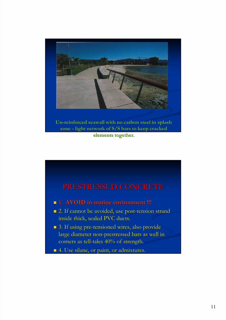
UnUn--reinforced seawall with no carbon steel in splashreinforced seawall with no carbon steel in splash
zonezone -- light network of S/S bars to keep crackedlight network of S/S bars to keep cracked
elements together.elements together.
PRESTRESSED CONCRETEPRESTRESSED CONCRETE
1.1. AVOID in marine environment !!! AVOID in marine environment !!!
2. If cannot be avoided, use post2. If cannot be avoided, use post--tension strandtension strand
inside thick, sealed PVC ducts.inside thick, sealed PVC ducts.
3. If using pre3. If using pre--tensioned wires, also providetensioned wires, also provide
large diameter nonlarge diameter non--prestressed bars as well inprestressed bars as well in
corners as tellcorners as tell--tales 40% of strength.tales 40% of strength.
4. Use silane, or paint, or admixtures.4. Use silane, or paint, or admixtures.
7/24/2019 Best Practice for Design of Maritime Structures
http://slidepdf.com/reader/full/best-practice-for-design-of-maritime-structures 12/25
12
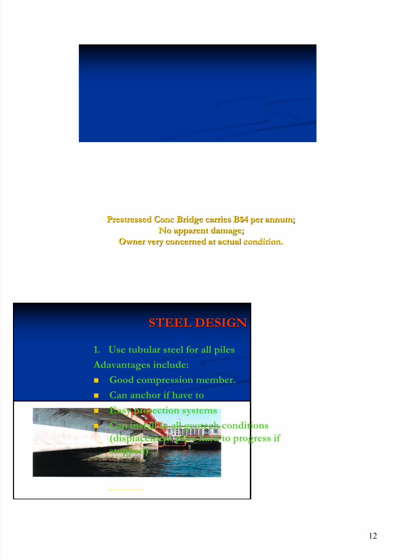
PrestressedPrestressed ConcConc Bridge carries B$4 per annum;Bridge carries B$4 per annum;
NoNo apparentapparent damage;damage;
Owner very concerned at actual condition.Owner very concerned at actual condition.
STEEL DESIGNSTEEL DESIGN
1. Use tubular steel for all piles
Adavantages include:
Good compression member.
Can anchor if have to
Easy protection systems
Can install in all geotech conditions
(displacement piles hard to progress if
stopped)

7/24/2019 Best Practice for Design of Maritime Structures
http://slidepdf.com/reader/full/best-practice-for-design-of-maritime-structures 13/25
13
Steel DesignSteel Design
CLAMPSCLAMPS
1.1. Clamps have advantage of allowingClamps have advantage of allowing
significant tolerance.significant tolerance.
2.2. Do not damage pile or member coatings.Do not damage pile or member coatings.
3.3. Can be used for pinned or fixed endCan be used for pinned or fixed end
connections.connections.4.4. Can be made by tradesman with a spanner.Can be made by tradesman with a spanner.
TIMBER TIMBER
Timber is highly durable strong and looks Timber is highly durable strong and looks
good.good.
Will last forever Will last forever -- if kept away from standingif kept away from standing
fresh water, and free of termites or marinefresh water, and free of termites or marineborers.borers.
Is being legislated out of reach.Is being legislated out of reach.
Relegated to small craft and recreationalRelegated to small craft and recreational
facilities.facilities.
7/24/2019 Best Practice for Design of Maritime Structures
http://slidepdf.com/reader/full/best-practice-for-design-of-maritime-structures 14/25
Lloyds List DCN Design of Maritime Structures
Maritime Structures 2006 __________________________________________________________________________________________________
________________________________________________________________________________
Andrew Patterson Page 1
Patterson Britton & Partners
06.11.19
BEST PRACTICE IN THE DESIGN OF MARITIME STRUCTURES
Andrew PattersonDirector, Patterson Britton & Partners, Consulting Engineers.
1. INTRODUCTION
This paper is to address the design of maritime structures in 2006. It looks at some ofthe recent trends in materials, design standards and the fact that the repair industry inmaritime structures is starting to outflank the growth in the construction industry.
We will look at the three main materials used in the construction of maritime works, thatis, concrete, steel and timber. There are a number of other materials, which for variousreasons such as cost and their stage of development have not yet become majorcontributors to the industry, but warrant some comment at the end of the discussion.
Of the main three materials, most of this paper will focus on concrete, because:
• Concrete is the predominantly used material in maritime works, but importantly isby far the most significant in terms of repair costs.
• Steel is a major construction material, particularly in offshore oil and gas platformsand now almost all piling is undertaken with tubular steel piles. But we all knowthe behaviour of steel, the fact that it rusts, and we need to keep cleaning andpainting it. Little has changed.
• Timber is a material which has had a considerable history in commercial wharves,but is now relegated to recreational structures and small craft facilities. Inaddition, the politicians have ill advisably, through sterilising forest resources,made timber structures more difficult to build. (Timber, from managed renewableforests is an excellent way to lock up carbon!)
However, we shall first address the problems of the most difficult material, concrete.
2. THE CONCRETE REPAIR INDUSTRY
In the last few decades, the poor performance of reinforced concrete structures insaltwater and sea-spray environments has lead to the development of a major newindustry, the concrete repair industry. All around Australia, in coastal towns and cities(the Gold Coast, Sydney beaches suburbs etc) one only has to look at the yellow pages
telephone directory under “Concrete Repair ” to see how large this industry now is. I
regard the growth of this industry as a signal of failure of our engineering profession.
In a recent article in Engineers Australia, attributed to Albert Van Greiken, it was noted
that in Germany a couple of years ago the annual cost of Concrete repairs was 90 billion
Euros, which compared to a new construction cost of concrete of 50 billion Euros.
It is not unusual in Australia to hear of repair costs of salt affected structures being atleast as much as the replacement cost of the structure, after as little as 15 years.
Structural engineers, by and large, don’t like failures and indeed we have very few, withthe exceptions of retaining walls after heavy rains (not a current problem), and maritimestructures when they start to prematurely spall due to salt attack on steel reinforcing.

7/24/2019 Best Practice for Design of Maritime Structures
http://slidepdf.com/reader/full/best-practice-for-design-of-maritime-structures 15/25
Lloyds List DCN Design of Maritime Structures
Maritime Structures 2006 __________________________________________________________________________________________________
________________________________________________________________________________
Andrew Patterson Page 2
Patterson Britton & Partners
06.11.19
It is our job as structural design engineers to reverse this trend of excessive growth in theconcrete repair industry, because it represents considerable loss (except of course toconcrete repair workers and the ubiquitous suppliers of repair products and systems) andit reflects badly on our own profession. One day we may even be held accountable forthese premature losses. What then?
The high costs for repair should be causing some designers to consider much morecarefully the way we design such structures. At present, it appears to me that there ismore expenditure and research into ways of repairing and maintaining salt affectedstructures such as coastal high-rise buildings and maritime concrete structures thanthought and consideration for ways of designing new structures that will last longerwithout this need for repair.
3. “GOOD CONCRETE - GOOD COVER !!!”
This is because the structural engineering industry appears to be riddled with doubt andconfusion as to how to design maritime concrete structures that will last. There aresignificant disparities between current design practice and the body of scientificknowledge. Also, engineers do not agree on the best way to design to ensure long-termdurability. Many engineers will still repeat the “motherhood statement” that all you needfor durable structures are “good concrete and good cover” and that the reasons for poordurability performance lie not with the designer/specifier but the contractor. This is ofcourse a nonsense, as has been demonstrated so many times by so many maritimestructures.
There is also wide disagreement on the benefits of galvanised steel reinforcement,stainless steel reinforcing, all the various concrete additives and the use of concrete
coatings.
This paper reviews very briefly the historic changes to the chemistry and physics ofcement itself, as well as pertinent aspects of concrete technology and describes howthese changes have influenced the performance of concrete structures. It alsorecommends ways of designing new maritime structures to improve their longevity.
4. RECENT HISTORY OF CONCRETE
It has been noted by some engineers that some older concrete maritime structures seemto perform better in terms of durability than more recently built maritime structures.
The greatest cause of premature failure of reinforced concrete structures is corrosion ofthe reinforcement. There are other potential causes of failure of structures which are notsignificant, which include(i) sulphate attack on the surface of concrete itself - not important in most concretestructures, but significant in sewerage structures and structures subject to high abrasion(eg., in the beach / surf zone);(ii) carbonation of concrete (which mostly affects porous and badly made concrete) and isan issue with downtown city high-rise but not often with salt affected structures;(iii) alkali aggregate (or alkali silicate) reaction (A.S.R). This latter generally occurs withdry-climate aggregates, eg in Western Australia, and with limestone type aggregates, egin the Central Queensland - Rockhampton area.
7/24/2019 Best Practice for Design of Maritime Structures
http://slidepdf.com/reader/full/best-practice-for-design-of-maritime-structures 16/25
Lloyds List DCN Design of Maritime Structures
Maritime Structures 2006 __________________________________________________________________________________________________
________________________________________________________________________________
Andrew Patterson Page 3
Patterson Britton & Partners
06.11.19
These three phenomena are not further discussed here, because such deteriorationmechanisms account for only a small proportion of concrete problems in maritimestructures in Australia. The greater majority of failures of maritime structures occurthrough corrosion of steel reinforcement and pre-stressing wires in the presence of highconcentrations of chloride ions as well as moisture and high oxygen availability.
5. CHANGES TO CEMENT
5.1 The Evidence
The construction industry is now able to supply much higher concrete strengths, bettercompaction equipment, variety of placement and improved curing, automated and veryaccurate batching plants and very good product quality control. Despite theseimprovements, performance is worse than the structures with poorly controlled concretebuilt 40 to 80 years ago, which used rough volume batch mixing and buckets and spades.
Some anecdotal accounts that our firm has been involved in include:
• A modern fishing jetty at Eden which started corrosion spalling only 7 years afterconstruction, and where repair costs equalled the replacement cost of the jetty.
• Relatively new RTA road bridges over saltwater estuaries, which have had toundergo repairs to chloride-affected piers in less than 20 years.
• A modern pre-stressed concrete beam footbridge, which had a self-weight of 22tonnes, less than 20 years old which failed suddenly as a workman walked acrossthe bridge.
• A pre-stressed concrete public jetty which failed after less than 20 years of life,and a similar structure, demolished due to corrosion of prestressing wires.
• Several old reinforced concrete wharves in Sydney Harbour built by Mr Walsh(trestle concrete seawalls-1920) and in the 1940s and 50s(eg., Jones Bay Wharf,Circular Quay pontoons, Ballast Point fuel wharf, CSR Pyrmont), with minimalevidence of corrosion.
• Some historic reinforced concrete structures (“Monier” structures) built by Sir JohnMonash have been demolished after 100 years in coastal environments whichwere still reasonably sound, having 6mm and 10mm bars with only 15mm coverwith 20MPa concrete.
5.2 Changes In Cement Chemistry
Cement chemistry was changed about three decades ago, to improve efficiencies in the
post-war booming building construction industry, (to the detriment of maritime structures.)
A primary component of cement is tri-calcium aluminate (chemical formula 3CaO. Al2O3,but written as C3 A), which amongst its other important properties as a binder, has theability to combine with and neutralise free chloride ions. Thus, with a greater content ofC3 A, there will be more absorption of chloride ions. Past studies have indicated thatcements containing 11 % to 15% of C3 A will effectively prevent chloride attack on steel. Apaper by Kirkby, Hinczak and Sioulas of Blue Circle Southern Cement (ref.1), undertook aliterature research into the history of cement manufacture over the last 70 years. In theirpaper, they observed that Ordinary Portland Cement (now Type GP) had a C3 A content of10% to 12% in earlier times but now has a C3 A contents of less than 4%. The highcontent of C3 A leads to longer hydration and curing times, which didn’t suit the high speed
turnaround required in the building boom of the 60s and 70s. The commercial pressures
7/24/2019 Best Practice for Design of Maritime Structures
http://slidepdf.com/reader/full/best-practice-for-design-of-maritime-structures 17/25
Lloyds List DCN Design of Maritime Structures
Maritime Structures 2006 __________________________________________________________________________________________________
________________________________________________________________________________
Andrew Patterson Page 4
Patterson Britton & Partners
06.11.19
driving this change means that high C3 A will not be available in maritime cements, as thecement for maritime structures forms only a small fraction of total cement sales.
5.3 Cement Fineness
Substantial increases in cement fineness as a result of improved grinding technologyhave also had a deleterious effect on durability of marine structures. Improved cementfineness allows greater chemical availability of the hydrating components, thus shorterhydration reaction time, allowing faster strength gains but unfortunately producing highergenerated temperatures, greater thermal expansion and after hardening, greater dryingshrinkage.
The author believes the use of coarse-ground cements with slower hydration and lowtemperature rise provided more durable structures. However, the world has moved onand these times have passed.
5.4 Concrete Mix Design
Mix designs have changed to suit the needs of the building construction industry.Developments in the industry and some of the problems these innovations have createdfor maritime structures include:
• use of transit-mixers, which result in long delays between batching and placing theconcrete. Also, these mixers have loss of control on the water cement ratio, asoperators can surreptitiously keep concrete "fresh" by adding more water duringtransit;
• concrete is now often pumped into place, requiring smaller size aggregate, with an
overall greater specific surface area and more workable, higher-slump, wetter mixes;
6. CONCRETE POROSITY
There is a strong belief that the problems of corrosion of steel reinforcement can besolved by the diligent application of the principles of “good concrete” and “good cover”.That is, the failures we have seen of premature corrosion are due almost entirely to thefailures to provide these. Some engineers, wrongly believe that concrete can be made tobe totally impermeable, thereby saving the steel from the ravages of chloride ingress.That is, all we need to do is to provide 65mm of cover and good dense strong 50 MPaconcrete, made with “marine” cement and voilá, our corrosion problems are solved. Theauthor is here to argue the fallacy of these beliefs.
If we start with the premise that truly impermeable concrete is never possible to achieve,and that concrete is a porous mass of continuous and interconnected capillaries (andmicro-cracks), waiting to soak up salt water, then our task of understanding the problemsof reinforced concrete corrosion, and solving them are half-way won.
Let us start with the chemistry and physics of the cement hydration process and considerthe volumes of water, weight of cement and the ultimate volume of voids left in theconcrete after the mixing water is used up in the cement hydration and drying process.
Take an example of a typical high grade marine concrete, with binder content of say 420
kg, and a water cement ratio of 0.45. The total volume of water in one cubic metre of this

7/24/2019 Best Practice for Design of Maritime Structures
http://slidepdf.com/reader/full/best-practice-for-design-of-maritime-structures 18/25
Lloyds List DCN Design of Maritime Structures
Maritime Structures 2006 __________________________________________________________________________________________________
________________________________________________________________________________
Andrew Patterson Page 5
Patterson Britton & Partners
06.11.19
concrete is thus 420 kg x 0.45 = 189kg or 0.189 cubic metres of water. The amount ofwater required to hydrate cement binder is 26% (+/-) of the weight of binder; whichequates to 109kg (0.109 cubic metres of water). That is, after the hydration process iscomplete, the concrete mass will contain about 0.189 minus 0.109 cubic metres = 0.080cu metres of free water. If this water then dries out of the concrete, the resultant volumeof voids in the capillaries is 8%. Typical porosity in sound concrete averages about 12%and can be as high as 20%, depending on W/C ratio.
Few engineers pause to consider that their “dense” concrete has 15% interconnectedvoids; that is, voids in the form of capillaries soaking up salt water and sea-spray.
7. OPTIONS TO PREVENT CONCRETE REINFOREMENT CORROSION
There are a number of ways we can prevent corrosion of the steel reinforcing in porousconcrete. These are grouped as follows:
(a) Chemicals in the concrete matrix which chemically bond (neutralising) the chlorideions.(b) Pore-blockers to prevent sea-water penetrating the concrete capillaries.(c) Protecting the surface of the steel reinforcing from corrosion reactions.(d) Providing non-corroding reinforcing.(e) Impressed current cathodic protection. (ICCP)
7.1 Chemical Absorption Agents and Electrolysis Prevention
The first system is a corrosion inhibitor, where the presence of inhibitor results in the free
chlorine molecules being neutralised. The greater the proportion of chemical added, themore chloride can be absorbed and the longer the structure will last.
The second system of corrosion inhibitor acts by forming chemical reactions at the steelsurface to prevent (a) anodic reactions; or (b) cathodic reactions; or (c) any electrolyticactivity.
Disadvantages of such additives are that (a) a large part of the chemical additive is“wasted” by being located in heart concrete remote from the sub-surface steel reinforcingunder attack; (b) addition of some of these chemicals adversely interfere with thebehaviour of the wet concrete and can change the requirements for handling, placing, andcompaction of the concrete.
Another form of protection is the use of penetrating corrosion inhibitor which is applied tothe surfaces of hardened concrete and penetrates through the capillaries to somedistance into the concrete.
7.2 Pore Blockers
There are currently four pore blockers:(i) Organic admixtures to wet concrete (Caltite, 3CC), which have secondary
reactions after the concrete has hydrated, and which form “fatty” organic depositswithin the capillaries making the concrete watertight.
7/24/2019 Best Practice for Design of Maritime Structures
http://slidepdf.com/reader/full/best-practice-for-design-of-maritime-structures 19/25
Lloyds List DCN Design of Maritime Structures
Maritime Structures 2006 __________________________________________________________________________________________________
________________________________________________________________________________
Andrew Patterson Page 6
Patterson Britton & Partners
06.11.19
(ii) Inorganic pore-blockers admixtures to wet concrete (Xypex), which havesecondary reactions to block the capillaries with inorganically grown dendriticcrystals.
(iii) Surface applied chemicals, sprayed onto the dry surface of hardened concrete,and which penetrates into the capillaries to form linings in these capillaries whichare hydrophobic, (Silane, siloxanes).
(iv) Surface applied chemical which penetrates the capillaries and forms a gel with thewater, blocking the pores (Aquron).
The advantage of these systems is that they recognise the naturally high permeability ofconcrete and address the problem by sealing off the surface capillaries.
Most of these materials have only recently been developed and thus their benefits over alife span of 50 years have yet to be confirmed.
Another method of protecting reinforced concrete is painting the concrete surface. Whilesome concrete structures are now painted such as residential and commercial buildingstructures for aesthetic reasons, few wharf structures are painted. Such paint coatingsprovide reinforced concrete with enormous added protection. The disadvantage is thatthe coating itself then requires maintenance.
7.3 Protect Steel from Corrosion
Rather than treat concrete to prevent access of the three ingredients required forcorrosion such as chloride, oxygen and moisture, the engineer can opt to make thereinforcing itself resistant to corrosion. Options include:(i) Coat the steel with epoxy.
(ii) Galvanised steel.(iii) Stainless steel or stainless steel clad reinforcing.(iv) Cathodic protection in the form of passive zinc alloy anodes buried in the concrete.(v) Normal impressed current cathodic protection (ICCP).(vi) Low-level impressed current preventative cathodic protection.
(i) Epoxy CoatingEpoxy coating of steel reinforcing has been carried out in the USA for several decades,but has not been used outside the USA. In theory the technique is perfectly satisfactory,but recent evidence from the USA has found that pinholes which occur in the coating(construction damage; film breakdown) has lead to anaerobic attack on the steel, causingthe reinforcing to turn into a soft black mass. There are emerging reports of majorinfrastructure loss due to anaerobic attack on plastic coated steel.
(ii) Galvanised SteelGalvanising of steel reinforcing has been carried out by some for many decades, but isstill the subject of controversy. Some experienced engineers still believe that galvanisingof steel is not worthwhile, because galvanising is not effective on steel exposed toseawater.
Prof. Stephen Yeomans, UNSW, has recently published a book “Galvanised SteelReinforcement in Concrete”, in which he notes that for an additional capital expenditure ofbetween 0.5% and 1.0% of a project cost, the time to initiation of corrosion of galvanised
reinforcing can be increased by a factor of 4 to 5 above that of black steel.

7/24/2019 Best Practice for Design of Maritime Structures
http://slidepdf.com/reader/full/best-practice-for-design-of-maritime-structures 20/25
Lloyds List DCN Design of Maritime Structures
Maritime Structures 2006 __________________________________________________________________________________________________
________________________________________________________________________________
Andrew Patterson Page 7
Patterson Britton & Partners
06.11.19
There are many advocates, including the author, of the use of galvanised steelreinforcing.
(iii) Stainless Steel ReinforcementThere is renewed interest in the use of stainless steel in the construction of maritimestructures. The use of Grade 316 or Duplex steel in the shape of deformed reinforcingbars is gaining popularity.
While the cost of this material is quite high (supply costs is of the order of five times thecost of black carbon steel), the option to use this should be carefully considered.Stainless steel can be mixed with black steel to reduce overall costs, placing the stainlesssteel only in the most aggressive environments. Another product available in the USA butnot yet in Australia is low carbon reinforcing steel with a surface veneer of stainless steel.
(iv) Embedded Zinc Anodes A recent development in the concrete repair industry has been the invention of embeddedzinc anodes which are used in concrete repairs after reinforcement corrosion and spallinghas occasioned repairs.
Patch repair of a concrete structure invariably leads to new corrosion next to the alreadypatched concrete, usually within a short time after the repair is completed. After therepair work is undertaken, the electrical polarity of the steel bar is reversed and theformerly quiescent area becomes anodic and immediately begins to suffer corrosion. Toovercome this, when undertaking repair works, a new zinc anode “biscuit” is beingmarketed to be installed on the perimeter of all such patch repairs. When the anode isattached to the repaired steel reinforcing just inside the perimeter, the zinc anode is
attacked, rather than the steel outside the perimeter, so that the corrosion of steelreinforcing is prevented. The life of this protection is a function of the size and distributionof zinc anode biscuits embedded in the concrete.
Extending this principle, the use of sacrificial zinc anodes, in conjunction with galvanisedsteel will extend the effective life of the galvanising in particularly aggressive zones of theconcrete by providing additional anodic mass of zinc.
(v) Impressed Current Cathodic Protection (ICCP)This is an “active” electrolytic protection system, at present usually retrofitted to salt-damaged structures, wherein all the reinforcing in the structure has to be exposed andbonded to conductors to become the cathodic system of electrodes inside the concrete. A series of anodes of a noble metal are also embedded in the concrete matrix, and anapplied low voltage (about one volt or so) is applied across the system. All the steelreinforcing thus has “cathodic protection” relative to the embedded anodes, and thecorrosion cells within a steel bar are overcome, so that corrosion is prevented.
Impressed current cathodic protection systems have been installed (retrofitted) to saltdamaged or potentially at-risk structures in a number of commercial ports in Australia.Port corporations generally comprise engineering, management and maintenancesystems which are required for a suitably maintained ICCP installation.

7/24/2019 Best Practice for Design of Maritime Structures
http://slidepdf.com/reader/full/best-practice-for-design-of-maritime-structures 21/25
Lloyds List DCN Design of Maritime Structures
Maritime Structures 2006 __________________________________________________________________________________________________
________________________________________________________________________________
Andrew Patterson Page 8
Patterson Britton & Partners
06.11.19
(v) Low level Impressed Current A recent advance in protection of steel reinforcement is to provide an impressed currentcathodic protection system to new structures, but using a very low level of current than forstandard ICCP.
7.4 Non Corrosive Reinforcing
These solutions are for the provision of reinforcing which, in the presence of chlorine,oxygen and moisture, does not deteriorate. Non corrosive reinforcing includes:(i) Plastic filament reinforcing.(ii) Carbon fibre.
(i) Plastic filament reinforcingThere are a number of purpose made high strength polymer fibre filaments (eg high
density polyethylene), which can be added to concrete mixes to provide tensile capacity toconcrete and which do not corrode. These materials including fibre composites beingtrialled in Toowoomba at present certainly have a place in the armoury of the maritimestructure designer, but have not reached mainstream design for long-span structures(suspended slabs etc).
(ii) Carbon Fibre ReinforcingCarbon fibre reinforcing is now being used to repair concrete structures. It has extremelyhigh tensile strength, and when bonded to the outside of damaged reinforced concreteelements can be a very effective repair system. It is currently too expensive to consideras a primary system of reinforcement in concrete structures.
8. MODIFYING MODERN STRUCTURAL CONCRETE DESIGN
Some of the problems we see in modern structures are not just due to changes in cementand concrete; they can also be attributed to changes in the structural design.
Thirty years ago, the standard design strength for concrete was 3000 psi or 20 MPa andspecial concrete for prestressed structures was 4,500 psi or 32 MPa. All steel reinforcingwas 250 MPa yield, with 22,000psi (150 MPa) maximum stress under full dead and liveload.
With modern steel reinforcing, Fy = 500 MPa, and concrete of F’c = 50 MPa easilyachievable, and with designers concentrating on the ultimate strength behaviour ofstructures rather than durability, we are observing slenderer structures with high stresslevels. The propensity for modern concrete structures to generally be stress-crackedrather than be generally be uncracked has had an adverse impact on the durability ofsaltwater structures. Cracking and micro-cracking due to shrinkage of concrete with highcement content and other high performance binders such as silica fume, blast furnaceslag which add strength but not pH buffering can also be adding to the problems.
9. DESIGN OF CONCRETE FOR DURABILITY
Maritime structure designers should consider the following when designing new concretestructures.

7/24/2019 Best Practice for Design of Maritime Structures
http://slidepdf.com/reader/full/best-practice-for-design-of-maritime-structures 22/25
Lloyds List DCN Design of Maritime Structures
Maritime Structures 2006 __________________________________________________________________________________________________
________________________________________________________________________________
Andrew Patterson Page 9
Patterson Britton & Partners
06.11.19
The following assumes that ICCP is not to be part of the protection system. Where ICCPis being used eg with large new port corporation owned facilities, normal reinforcedconcrete design can be applied, although caution needs to be used, in that in future suchICCP may not be functioning properly, or at all .
Designer should:
(a) Avoid reinforcing altogether. If possible, use only mass concrete, particularly in thesplash zone. Seawalls, stub columns or plinths, revetment armour units, revetmentslopes and so on can sometimes be designed as mass concrete, and in a harsh splashenvironment, this is encouraged. If there is concern about cracking of an element whichcould lead to breaking up of the mass concrete structure, then consideration could begiven to use of a lightweight grillage of thin stainless steel bars (3mm to 6mm diameter) atsay moderate 300mm to 500mm centres, to hold such cracked concrete elements inplace. (Refer to the drawing attached of the Cairns seawall for the Cairns Esplanade
project which has all main steel buried and the splash zone concrete is plain concrete withlight stainless steel (12mm bars @ 400mm centres)
(b) Avoid thin concrete sections in the most aggressive (wetting and drying) zones.Reinforced concete piles are now seldom used in major structures because theirperformance in the splash zone has been poor. Steel tube piles with factory appliedcoatings or petrolatum tapes are almost universally used in the tidal and wave zone formarine structures.
(c) Minimise the uses of thin sections generally. Experience has shown that thick“chunky” concrete, with minimal proportions of steel will generally outlast high-efficiencydesign with “balanced” steel reinforcement ratios. A wharf deck with conventional pile
headstocks, beams and a slab deck will have much greater corrosion potential than a flatplate slab supported on pile capitals.
(d) Design for low stresses in steel reinforcing. At maximum working stress steel shouldbe at about 150 Mpa, similar to water retaining reservoirs and tanks At the same time,use a small number of large bars at large spacing, rather lots of small bars at closespacing. [While this is against the conventional theory of crack-width minimisation, itdoes however reduce the total area of steel exposed to corrosion]. Because steelstresses are kept generally low, flexural cracking should not be critical.
(e) Use galvanised steel reinforcing, throughout the structure, and weld all bars together,preferably before hot dip galvanising. In especially harsh areas (the splash zone, add
embedded zinc anodes, bonded to the reinforcing cage. (Refer to Lee Wharf Seawallwhich has all welded steel reinforcing cages, hot dip galvanised after fabrication, andadditional Galvashield passive zinc anodes attached to the steel cages.)
(f) Apply a surface coating to the concrete such as 100% silane or other chemical whichblocks pores. Alternatively, apply a conventional paint coating system which may needre-coating every 10 years or so.
10. PRESTRESSED CONCRETE
Prestressed pretensioned concrete (ie using unprotected steel strand) is a specialproblem in the marine environment.

7/24/2019 Best Practice for Design of Maritime Structures
http://slidepdf.com/reader/full/best-practice-for-design-of-maritime-structures 23/25
Lloyds List DCN Design of Maritime Structures
Maritime Structures 2006 __________________________________________________________________________________________________
________________________________________________________________________________
Andrew Patterson Page 10
Patterson Britton & Partners
06.11.19
When normal reinforced structures are affected by seawater, the structure providesample external evidence of distress in the form of concrete spalling, rust staining andsubsequent exposure and encrustation of steel. Furthermore, such a reinforced concretestructure can appear to be in a very dilapidated condition while it has not lost much of itsstrength. This is because the principal reinforcing bars are usually large (eg 20 to 28 mmdiameter or so), and steel corrosion occupies seven to ten times the volume of theoriginal steel. For example if a 24 mm bar lost 0.2 mm depth in corrosion, (which is aloss of capacity of only 3.3%), it will have grown in diameter to some 27 mm, causingsplitting, spalling and rust staining of the surrounding concrete. Furthermore, if the steelreinforcement is not repaired, the eventual failure of the reinforced structure will be byyielding of steel, which results in the formation of a plastic hinge with gross deflection wellbefore the structure actually breaks.
On the other hand, prestressed concrete has very small steel volumes and these candeteriorate severely without exhibiting any visible distress in the structure. Steel strands
are usually small diameter (12.5 mm), with large surface area comprising a number ofsmaller wires wound together. (Woven wires compounds the problem, since the voidsbetween the wires are conduits for seawater, and also are spaces into which corrosionproduct fills before the corrosion product begins to disrupt the concrete).
Strands are stressed to 800 to 1000 MPa. The effect of 0.2 mm corrosion on the 3 mmwires making up a 12.5mm prestressing strand will result in a reduction of capacity ofsome 25%.
Apart from oxidation of the steel in a chloride environment, steel under very high tensilestress and aggressive environment can suffer other forms of strength loss such as stresscorrosion and hydrogen embrittlement. These can occur with little or no volumetric
change, and hence no warning on the surface of the concrete.
A pretensioned concrete beams in an aggressive, high oxygen, water and chlorideenvironment could well be near failure condition while exhibiting no external evidence ofthis condition. A further difficulty for the forensic engineer is that there is very little he cando to establish the condition of the steel tendons. Unlike reinforced concrete structures,partial demolition of the stressed concrete to inspect the tendons results in irreparabledamage and weakening of the beams, damage which cannot be repaired by replacing thesteel and concrete.
However, the worst aspect of pretensioned concrete is that failure, when it does occur, isin the form of tensile failure of the concrete due to loss of compressive pre-stress.Tensile failure of concrete occurs suddenly and without any warning.
In designing pretensioned concrete in a maritime structure, it is advisable to also providesome non-prestressed reinforcement in the form of large diameter bars, with the same (ormarginally less) cover as the prestressing wire. The purpose of this steel is to act as“tell-tale” warning that chloride effects are causing problems inside the member.
The use of post tensioned structures, where stressing cables are fully enclosed in astrong waterproof durable duct such as HDPE water pipe or similar, and with dead andlive stressing heads encased in epoxy should not have any problems of durability.
7/24/2019 Best Practice for Design of Maritime Structures
http://slidepdf.com/reader/full/best-practice-for-design-of-maritime-structures 24/25
Lloyds List DCN Design of Maritime Structures
Maritime Structures 2006 __________________________________________________________________________________________________
________________________________________________________________________________
Andrew Patterson Page 11
Patterson Britton & Partners
06.11.19
11. STEEL DESIGN
There is not a great deal to be said about steel design in the modern day and age. Asengineers, we are all familiar with the properties of steel, its strength, its tendency tocorrode and its need for constant maintenance. Some design pointers for steel include:
11.1 PilingMaritime piling should, in almost every case, be designed with tubular steel piles. Thereasons and advantages of steel tubes are:
• Tube piles are efficient compression members, and when required to provide upliftcapacity, their large perimeter allows for good uplift friction.
• They can be installed under almost any geotechnical condition. When concretedisplacement piles fail to penetrate sufficiently into hard strata, there are few
options, whereas with a tube pile, drilling inside the pile and driving is a solution.
• Tube piles, (as opposed to “H” piles of square or the old BHP hot rolled HP piles),are easily protected with sprayed-on, baked-on, wrapped-on, protective coatings.Some of these factory applied coatings now have exceeding long design life, suchas triple coated polyethylene wraps, or baked on epoxy coatings.
A word of caution regarding steel piles is possible high rates of corrosion whichsometimes occur at or below the low water level. This phenomenon has lead to someunexpected severe pile damage in recent years.
11.2 Clamps A particular favourite design trick of mine is the use of clamps. Clamps on steel tubepiles can be designed to make very strong moment or pin connections onto driven steelpiles, without the need for welding or in any way adversely affecting the protectivecoatings of the steel members. Clamps are more expensive to make, but are madeunder controlled conditions in the fabricator’s shop; can be well protected; and theconnection is easily made with a diver armed with no more than a spanner, to produce a100% satisfactory connection.
The advantages of clamps are that they permit tolerance in driving piles, tolerance inlocation of the position of the clamp and often the length of the connected member.Using painted steel clamps, with stainless steel bolts, clamps steel structures should have
a considerable maintenance free design life.
12. TIMBER DESIGN
Timber is a very strong durable material which will last for hundreds of years provided it isnot exposed to static fresh water or termites. Some of the timber wharves in Sydney builtby Mr Walsh 100 years ago are in very good condition where they are protected fromrainwater runoff and have not been subject to termites.
There are issues about timber piles in the sea with marine organisms eating or living inthe timber, and again the use of biological control (copper chrome arsenate and creosotepressure impregnation) or piles wrapped or jacketed in plastic coatings will ensure
durable pile structures.
7/24/2019 Best Practice for Design of Maritime Structures
http://slidepdf.com/reader/full/best-practice-for-design-of-maritime-structures 25/25
Lloyds List DCN Design of Maritime Structures
Maritime Structures 2006 __________________________________________________________________________________________________
________________________________________________________________________________
Andrew Patterson Page 12
Successful timber structures is a maritime environment have the following attributes:
• Timber members should be thick and chunky.
• Deck bearers never less than 100mm thick, decking not less than 45mm thick.
•
Drill holes should be oversize to allow for shrinkage.• Waterproof membranes should be installed on tops of members to stop ponding of
water and dry rot.
• Exposed tops of piles should be sealed with fibreglass to prevent ingress ofrainwater into the pile, causing internal rot.
• Use stainless steel bolts and deck screws.
• Allow for shrinkage of green timber and swelling of kiln-dried timber.
Timber structures particularly exposed timber decks cannot have a design life past 25years and so can only be used on small craft and recreational facilities.
13. OTHER MATERIALS
Some materials currently gaining favour in the maritime structures field, but are not yetcommonly used, due to their high cost or the early stage of development, include:
13.1 Aluminium A large number of smaller structures are built with aluminium, where light weight andstrength is important. The most familiar of these are marina gangways and marina fittingssuch as cleats, as well as low level stairways down to below high water. Aluminium isanodic with respect to ferric materials so needs proper insulation detailing.
13.2 Stainless Steel
Stainless steel is a useful material for small elements which are immersed in seawater,such as safety egress ladders, submerged stairways and fixings.
Stainless steel should be used with care, as granular corrosion (resulting from heattreatment not being followed by proper passivation) has caused very rapid andunexpected failure of stainless steel. Also, anaerobic conditions have been known togive unexpected corrosion results.
13.3 Concrete CompositesThere are some interesting developments using cementitious concrete mixed with fibrematerials to form composites with high tensile capacity as being developed by SouthernCross University which may lead the way to some high durable, strong concrete
members. This work is still in the research and development phase.
14. REFERENCES1 . Kirkby, Hinczak, Sioulas, (1997). "Durability of Marine Structures -A HistoricalPerspective ". Technical paper for Blue Circle Southern Cement Ltd, 1997.2. Baweja, D, (CSR), Prof Roper, H, (Univ of Sydney), Sirivivatnanon, V, (CSIRO),"Durability of Plain and Blended Cement Concretes as Predicted by Corrosion Potentials", Australian Civil Engineering Transactions, August 1995.3. Guirguis, S, (19 89), "Durable Concrete Structures ", Cement & Concrete Associationof Australia, Technical Note TN5, March 1989.4. Stephen R Yeomans. “Galvanized Steel Reinforcement in Concrete”, ElseverePublishers, Oxford UK, 2004.