bengine - myedocs.com · em-1 engine mechanical bengine contents c d e f g h i j k l m section a em...
TRANSCRIPT

EM-1
ENGINE MECHANICAL
B ENGINE
CONTENTS
C
D
E
F
G
H
I
J
K
L
M
SECTION
A
EM
Revision: November 2004 2005 Frontier
QR
PRECAUTIONS .......................................................... 5Precautions for Drain Engine Coolant and EngineOil ............................................................................. 5Precautions for Disconnecting Fuel Piping .............. 5Precautions for Removal and Disassembly ............. 5Precautions for Inspection, Repair and Replace-ment ......................................................................... 5Precautions for Assembly and Installation ............... 5Parts Requiring Angle Tightening ............................. 5Precautions for Liquid Gasket .................................. 6
REMOVAL OF LIQUID GASKET SEALING .......... 6LIQUID GASKET APPLICATION PROCEDURE..... 6
PREPARATION ........................................................... 7Special Service Tools ............................................... 7Commercial Service Tools ........................................ 9
NOISE, VIBRATION AND HARSHNESS (NVH)TROUBLESHOOTING ...............................................11
NVH Troubleshooting — Engine Noise ...................11Use the Chart Below to Help You Find the Causeof the Symptom. ..................................................... 12
DRIVE BELTS ........................................................... 13Checking Drive Belt ................................................ 13Tension Adjustment ................................................ 13Removal and Installation ........................................ 13
REMOVAL ........................................................... 13INSTALLATION ................................................... 14
Removal and Installation of Drive Belt Auto-Ten-sioner ..................................................................... 14
REMOVAL ........................................................... 14INSTALLATION ................................................... 14
AIR CLEANER AND AIR DUCT ............................... 15Removal and Installation ........................................ 15
REMOVAL ........................................................... 15INSPECTION AFTER REMOVAL ....................... 15INSTALLATION ................................................... 15
Changing Air Cleaner Filter .................................... 16REMOVAL ........................................................... 16INSTALLATION ................................................... 16
INTAKE MANIFOLD ................................................. 17Removal and Installation ........................................ 17
REMOVAL ........................................................... 17INSTALLATION ................................................... 18INSPECTION AFTER INSTALLATION ................ 19
EXHAUST MANIFOLD AND THREE WAY CATA-LYST .......................................................................... 20
Removal and Installation ........................................ 20REMOVAL ........................................................... 20INSPECTION AFTER REMOVAL ....................... 21INSTALLATION ................................................... 21
OIL PAN .................................................................... 22Removal and Installation ........................................ 22
REMOVAL ........................................................... 22INSTALLATION ................................................... 23INSPECTION AFTER INSTALLATION ................ 23
IGNITION COIL ......................................................... 25Removal and Installation ........................................ 25
REMOVAL ........................................................... 25INSTALLATION ................................................... 25
SPARK PLUG (PLATINUM-TIPPED TYPE) ............. 26Removal and Installation ........................................ 26
REMOVAL ........................................................... 26INSPECTION AFTER REMOVAL ....................... 26INSTALLATION ................................................... 27
FUEL INJECTOR AND FUEL TUBE ........................ 28Removal and Installation ........................................ 28
REMOVAL ........................................................... 28INSTALLATION ................................................... 30INSPECTION AFTER INSTALLATION ................ 32
ROCKER COVER ..................................................... 33Removal and Installation ........................................ 33
REMOVAL ........................................................... 33INSTALLATION ................................................... 34
CAMSHAFT .............................................................. 35Removal and Installation ........................................ 35
REMOVAL ........................................................... 35INSPECTION AFTER REMOVAL ....................... 37INSTALLATION ................................................... 40

EM-2Revision: November 2004 2005 Frontier
INSPECTION AFTER INSTALLATION ................ 43Valve Clearance ...................................................... 44
INSPECTION ....................................................... 44ADJUSTMENT .................................................... 45
TIMING CHAIN .......................................................... 47Removal and Installation ........................................ 47
REMOVAL ........................................................... 48INSPECTION AFTER REMOVAL ........................ 51INSTALLATION .................................................... 51INSPECTION AFTER INSTALLATION ................ 55
OIL SEAL .................................................................. 56Removal and Installation of Valve Oil Seal ............. 56
REMOVAL ........................................................... 56INSTALLATION .................................................... 56
Removal and Installation of Front Oil Seal ............. 56REMOVAL ........................................................... 56INSTALLATION .................................................... 57
Removal and Installation of Rear Oil Seal .............. 57REMOVAL ........................................................... 57INSTALLATION .................................................... 57
CYLINDER HEAD ..................................................... 59On-Vehicle Service ................................................. 59
CHECKING COMPRESSION PRESSURE ......... 59Removal and Installation ........................................ 60
REMOVAL ........................................................... 60INSPECTION AFTER REMOVAL ........................ 61INSTALLATION .................................................... 62INSPECTION AFTER INSTALLATION ................ 62
Disassembly and Assembly .................................... 63DISASSEMBLY ................................................... 63ASSEMBLY ......................................................... 64
Inspection After Disassembly ................................. 66VALVE DIMENSIONS .......................................... 66VALVE GUIDE CLEARANCE .............................. 66VALVE GUIDE REPLACEMENT ......................... 66VALVE SEAT CONTACT ..................................... 68VALVE SEAT REPLACEMENT ........................... 68VALVE SPRING SQUARENESS ......................... 69VALVE SPRING DIMENSIONS AND VALVESPRING PRESSURE LOAD ............................... 69
ENGINE ASSEMBLY ................................................ 70Removal and Installation ........................................ 70
REMOVAL ........................................................... 71INSTALLATION .................................................... 72INSPECTION AFTER INSTALLATION ................ 72
CYLINDER BLOCK ................................................... 74Disassembly and Assembly .................................... 74
DISASSEMBLY ................................................... 75ASSEMBLY ......................................................... 79
How to Select Piston and Bearing .......................... 84DESCRIPTION .................................................... 84HOW TO SELECT PISTON ................................. 84HOW TO SELECT CONNECTING ROD BEAR-ING ...................................................................... 85
HOW TO SELECT MAIN BEARING ....................87Inspection After Disassembly ..................................91
CRANKSHAFT END PLAY ..................................91CONNECTING ROD SIDE CLEARANCE ...........91PISTON TO PISTON PIN OIL CLEARANCE .......91PISTON RING SIDE CLEARANCE .....................92PISTON RING END GAP ....................................92CONNECTING ROD BEND AND TORSION .......93CONNECTING ROD BIG END DIAMETER ........93CONNECTING ROD BUSHING OIL CLEAR-ANCE ...................................................................93CYLINDER BLOCK DISTORTION ......................94MAIN BEARING HOUSING INNER DIAMETER...95PISTON TO CYLINDER BORE CLEARANCE ....95CRANKSHAFT MAIN JOURNAL DIAMETER .....96CRANKSHAFT PIN JOURNAL DIAMETER ........97OUT-OF-ROUND AND TAPER OF CRANK-SHAFT .................................................................97CRANKSHAFT RUNOUT ....................................97CONNECTING ROD BEARING OIL CLEAR-ANCE ...................................................................97MAIN BEARING OIL CLEARANCE .....................98MAIN BEARING CRUSH HEIGHT ......................99CONNECTING ROD BEARING CRUSHHEIGHT ...............................................................99LOWER CYLINDER BLOCK MOUNTING BOLTOUTER DIAMETER .............................................99CONNECTING ROD BOLT OUTER DIAMETER...99FLYWHEEL DEFLECTION (M/T MODELS) ......100MOVEMENT AMOUNT OF FLYWHEEL (M/TMODELS) ...........................................................100
SERVICE DATA AND SPECIFICATIONS (SDS) ....101Standard and Limit ................................................101
GENERAL SPECIFICATIONS ...........................101DRIVE BELT ......................................................101EXHAUST MANIFOLD AND THREE WAY CAT-ALYST ASSEMBLY ............................................101SPARK PLUG ....................................................101CYLINDER HEAD ..............................................101VALVE ................................................................102CAMSHAFT AND CAMSHAFT BEARING .........106CYLINDER BLOCK ............................................106PISTON, PISTON RING AND PISTON PIN ......108CONNECTING ROD ..........................................109CRANKSHAFT ...................................................109MAIN BEARING ................................................. 111CONNECTING ROD BEARING ......................... 112
VQ
PRECAUTIONS .......................................................113Precautions for Drain Engine Coolant ................... 113Precautions for Disconnecting Fuel Piping ........... 113Precautions for Removal and Disassembly .......... 113Precautions for Inspection, Repair and Replace-ment ...................................................................... 113Precautions for Assembly and Installation ............ 113

EM-3
C
D
E
F
G
H
I
J
K
L
M
EM
A
Revision: November 2004 2005 Frontier
Parts Requiring Angle Tightening ..........................113Precautions for Liquid Gasket ...............................114
REMOVAL OF LIQUID GASKET SEALING .......114LIQUID GASKET APPLICATION PROCEDURE..114
PREPARATION ........................................................115Special Service Tools ............................................115Commercial Service Tools .....................................117
NOISE, VIBRATION AND HARSHNESS (NVH)TROUBLESHOOTING .............................................119
NVH Troubleshooting —Engine Noise ..................119Use the Chart Below to Help You Find the Causeof the Symptom .................................................... 120
ENGINE ROOM COVER ........................................ 121Removal and Installation ...................................... 121
REMOVAL ......................................................... 121INSTALLATION ................................................. 121
DRIVE BELTS ......................................................... 122Checking Drive Belts ............................................ 122Tension Adjustment .............................................. 122Removal and Installation ...................................... 122
DRIVE BELT ..................................................... 122INSTALLATION ................................................. 123
Drive Belt Auto Tensioner and Idler Pulley ........... 123REMOVAL ......................................................... 123INSTALLATION ................................................. 123
AIR CLEANER AND AIR DUCT ............................. 124Removal and Installation ...................................... 124
REMOVAL ......................................................... 124INSPECTION AFTER REMOVAL ..................... 124INSTALLATION ................................................. 124
Changing Air Cleaner Filter .................................. 124REMOVAL ......................................................... 124INSTALLATION ................................................. 124
INTAKE MANIFOLD COLLECTOR ........................ 125Removal and Installation ...................................... 125
REMOVAL ......................................................... 126INSTALLATION ................................................. 127
INTAKE MANIFOLD ............................................... 128Removal and Installation ...................................... 128
REMOVAL ......................................................... 128INSPECTION AFTER REMOVAL ..................... 128INSTALLATION ................................................. 129
EXHAUST MANIFOLD AND THREE WAY CATA-LYST ....................................................................... 130
Removal and Installation ...................................... 130REMOVAL (LEFT BANK) .................................. 130INSPECTION AFTER REMOVAL ..................... 131INSTALLATION (LEFT BANK) .......................... 132REMOVAL (RIGHT BANK) ............................... 133INSPECTION AFTER REMOVAL ..................... 133INSTALLATION (RIGHT BANK) ........................ 134
OIL PAN AND OIL STRAINER ............................... 135Removal and Installation ...................................... 135
REMOVAL (LOWER) ......................................... 135INSPECTION AFTER REMOVAL ..................... 136INSTALLATION (LOWER) ................................. 136INSPECTION AFTER INSTALLATION .............. 137REMOVAL (UPPER) ......................................... 137INSPECTION AFTER REMOVAL ..................... 138INSTALLATION (UPPER) .................................. 138INSPECTION AFTER INSTALLATION .............. 139
IGNITION COIL ....................................................... 140Removal and Installation ...................................... 140
REMOVAL (LEFT BANK) .................................. 140INSTALLATION (LEFT BANK) .......................... 140REMOVAL (RIGHT BANK) ................................ 140INSTALLATION (RIGHT BANK) ........................ 140
SPARK PLUG (PLATINUM-TIPPED TYPE) ........... 141Removal and Installation ...................................... 141
REMOVAL ......................................................... 141INSPECTION AFTER REMOVAL ..................... 141INSTALLATION ................................................. 142
FUEL INJECTOR AND FUEL TUBE ...................... 143Removal and Installation ...................................... 143
REMOVAL ......................................................... 143INSTALLATION ................................................. 146INSPECTION AFTER INSTALLATION .............. 148
ROCKER COVER ................................................... 149Removal and Installation ...................................... 149
REMOVAL (LEFT BANK) .................................. 149INSTALLATION (LEFT BANK) .......................... 150REMOVAL (RIGHT BANK) ................................ 151INSTALLATION (RIGHT BANK) ........................ 152
FRONT TIMING CHAIN CASE ............................... 154Removal and Installation ...................................... 154
REMOVAL ......................................................... 154INSTALLATION ................................................. 158INSPECTION AFTER INSTALLATION .............. 161
TIMING CHAIN ........................................................ 163Removal and Installation ...................................... 163
REMOVAL ......................................................... 164INSPECTION AFTER REMOVAL ..................... 171INSTALLATION ................................................. 172INSPECTION AFTER INSTALLATION .............. 182
CAMSHAFT ............................................................ 183Removal and Installation ...................................... 183
REMOVAL ......................................................... 184INSPECTION AFTER REMOVAL ..................... 185INSTALLATION ................................................. 188INSPECTION AFTER INSTALLATION .............. 191
Valve Clearance ................................................... 192INSPECTION .................................................... 192ADJUSTMENT .................................................. 195
OIL SEAL ................................................................ 197Removal and Installation of Valve Oil Seal ........... 197
REMOVAL ......................................................... 197INSTALLATION ................................................. 197
Removal and Installation of Front Oil Seal ........... 198REMOVAL ......................................................... 198

EM-4Revision: November 2004 2005 Frontier
INSTALLATION .................................................. 198Removal and Installation of Rear Oil Seal ............ 198
REMOVAL ......................................................... 198INSTALLATION .................................................. 199
CYLINDER HEAD ................................................... 200On-Vehicle Service ............................................... 200
CHECKING COMPRESSION PRESSURE ....... 200Removal and Installation ...................................... 201
REMOVAL ......................................................... 201INSPECTION AFTER REMOVAL ...................... 202INSTALLATION .................................................. 203INSPECTION AFTER INSTALLATION .............. 204
Disassembly and Assembly .................................. 205DISASSEMBLY ................................................. 205ASSEMBLY ....................................................... 206
Inspection After Disassembly ............................... 207VALVE DIMENSIONS ........................................ 207VALVE GUIDE CLEARANCE ............................ 207VALVE GUIDE REPLACEMENT ....................... 208VALVE SEAT CONTACT ................................... 209VALVE SEAT REPLACEMENT ......................... 209VALVE SPRING SQUARENESS ....................... 210VALVE SPRING DIMENSIONS AND VALVESPRING PRESSURE LOAD ............................. 211
ENGINE ASSEMBLY .............................................. 212Removal and Installation ...................................... 212
REMOVAL ......................................................... 213INSTALLATION .................................................. 214INSPECTION AFTER INSTALLATION .............. 214
CYLINDER BLOCK ................................................. 215Disassembly and Assembly .................................. 215
DISASSEMBLY ................................................. 216ASSEMBLY ....................................................... 220
How to Select Piston and Bearing ........................ 226DESCRIPTION .................................................. 226HOW TO SELECT PISTON ............................... 226HOW TO SELECT CONNECTING ROD BEAR-ING .................................................................... 227
HOW TO SELECT MAIN BEARING ..................228Inspection After Disassembly ................................231
CRANKSHAFT END PLAY ................................231CONNECTING ROD SIDE CLEARANCE .........231PISTON TO PISTON PIN OIL CLEARANCE .....231PISTON RING SIDE CLEARANCE ...................232PISTON RING END GAP ..................................232CONNECTING ROD BEND AND TORSION .....233CONNECTING ROD BIG END DIAMETER ......233CONNECTING ROD BUSHING OIL CLEAR-ANCE .................................................................233CYLINDER BLOCK DISTORTION ....................234MAIN BEARING HOUSING INNER DIAMETER.235PISTON TO CYLINDER BORE CLEARANCE ..235CRANKSHAFT MAIN JOURNAL DIAMETER ...236CRANKSHAFT PIN JOURNAL DIAMETER ......237CRANKSHAFT OUT-OF-ROUND AND TAPER.237CRANKSHAFT RUNOUT ..................................237CONNECTING ROD BEARING OIL CLEAR-ANCE .................................................................237MAIN BEARING OIL CLEARANCE ...................238CRUSH HEIGHT OF MAIN BEARING ..............239CRUSH HEIGHT OF CONNECTING RODBEARING ...........................................................239LOWER CYLINDER BLOCK BOLT OUTERDIAMETER ........................................................239CONNECTING ROD BOLT OUTER DIAMETER.240DRIVE PLATE ....................................................240OIL JET ..............................................................240OIL JET RELIEF VALVE ....................................240
SERVICE DATA AND SPECIFICATIONS (SDS) ....241Standard and Limit ................................................241
GENERAL SPECIFICATIONS ...........................241DRIVE BELT ......................................................242INTAKE MANIFOLD COLLECTOR, INTAKEMANIFOLD AND EXHAUST MANIFOLD ..........242SPARK PLUG ....................................................242CAMSHAFT AND CAMSHAFT BEARING .........243CYLINDER HEAD ..............................................245CYLINDER BLOCK ............................................248PISTON, PISTON RING AND PISTON PIN ......249CONNECTING ROD ..........................................250CRANKSHAFT ...................................................251MAIN BEARING .................................................252CONNECTING ROD BEARING .........................253

PRECAUTIONS
EM-5
[QR]
C
D
E
F
G
H
I
J
K
L
M
A
EM
Revision: November 2004 2005 Frontier
PRECAUTIONS PFP:00001
Precautions for Drain Engine Coolant and Engine Oil EBS00NGC
Drain engine coolant and engine oil when the engine is cooled.
Precautions for Disconnecting Fuel Piping EBS00NGD
● Before starting work, make sure no fire or spark producing items are in the work area.● Release fuel pressure before disassembly.● After disconnecting pipes, plug openings to stop fuel leakage.
Precautions for Removal and Disassembly EBS00NGE
● When instructed to use special service tools, use the specified tools. Always be careful to work safely,avoid forceful or uninstructed operations.
● Exercise maximum care to avoid damage to mating or sliding surfaces.● Cover openings of engine system with a tape or the equivalent, if necessary, to seal out foreign materials.● Mark and arrange disassembly parts in an organized way for easy troubleshooting and re-assembly.● When loosening nuts and bolts, as a basic rule, start with the one furthest outside, then the one diagonally
opposite, and so on. If the order of loosening is specified, do exactly as specified. Power tools may beused where noted in the step.
Precautions for Inspection, Repair and Replacement EBS00NGF
Before repairing or replacing, thoroughly inspect parts. Inspect new replacement parts in the same way, andreplace if necessary.
Precautions for Assembly and Installation EBS00NGG
● Use torque wrench to tighten bolts or nuts to specification.● When tightening nuts and bolts, as a basic rule, equally tighten in several different steps starting with the
ones in center, then ones on inside and outside diagonally in this order. If the order of tightening is speci-fied, do exactly as specified.
● Replace with new gasket, packing, oil seal or O-ring.● Dowel pins are used for several parts alignment. When replacing and reassembling parts with dowel pins,
make sure that dowel pins are installed in the original position.● Thoroughly wash, clean, and air-blow each part. Carefully check engine oil or engine coolant passages for
any restriction and blockage.● Avoid damaging sliding or mating surfaces. Completely remove foreign materials such as cloth lint or dust.
Before assembly, oil sliding surfaces well.● Release air within route when refilling after draining engine coolant.● Before starting the engine, apply fuel pressure to fuel lines with turning ignition switch “ON” (with the
engine stopped). Then make sure there are no leaks at fuel line connections.● After repairing, start the engine and increase engine speed to check engine coolant, fuel, engine oil, and
exhaust gases for leakage.
Parts Requiring Angle Tightening EBS00NGH
● For the final tightening of the following engine parts use Tool:
– Cylinder head bolts– Lower cylinder block bolts– Connecting rod cap bolts– Crankshaft pulley bolt (No angle wrench is required as bolt flange is provided with notches for angle tight-
ening)● Do not use a torque value for final tightening.● The torque value for these parts are for a preliminary step.● Ensure thread and seat surfaces are clean and coated with engine oil.
Tool number : KV10112100 (BT-8653-A)

EM-6Revision: November 2004
[QR]PRECAUTIONS
2005 Frontier
Precautions for Liquid Gasket EBS00NGI
REMOVAL OF LIQUID GASKET SEALING● After removing nuts and bolts, separate the mating surface and
remove old liquid gasket sealing using Tool.
CAUTION:Be careful not to damage the mating surfaces.
● Tap seal cutter to insert it, and then slide it by tapping on theside as shown.
● In areas where Tool is difficult to use, use plastic hammer tolightly tap the parts, to remove it.CAUTION:If for some unavoidable reason tool such as screwdriver isused, be careful not to damage the mating surfaces.
LIQUID GASKET APPLICATION PROCEDURE1. Using scraper, remove old liquid gasket adhering to the gasket
application surface and the mating surface.● Remove liquid gasket completely from the groove of the gas-
ket application surface, bolts, and bolt holes.2. Thoroughly clean the mating surfaces and remove adhering
moisture, grease and foreign materials.
3. Attach liquid gasket tube to Tool.
Use Genuine RTV Silicone Sealant or equivalent. Refer toGI-45, "Recommended Chemical Products and Sealants" .
4. Apply liquid gasket without breaks to the specified location withthe specified dimensions.● If there is a groove for liquid gasket application, apply liquid
gasket to the groove.
● As for bolt holes, normally apply liquid gasket inside theholes. Occasionally, it should be applied outside the holes.Make sure to read the text of this manual.
● Within five minutes of liquid gasket application, install the mat-ing component.
● If liquid gasket protrudes, wipe it off immediately.● Do not retighten nuts or bolts after the installation.● After 30 minutes or more have passed from the installation, fill
engine oil and engine coolant.CAUTION:If there are specific instructions in this manual, observethem.
Tool number : KV10111100 (J-37228)
WBIA0566E
PBIC0003E
Tool number : WS39930000 ( — )
WBIA0567E
SEM159F

PREPARATION
EM-7
[QR]
C
D
E
F
G
H
I
J
K
L
M
A
EM
Revision: November 2004 2005 Frontier
PREPARATION PFP:00002
Special Service Tools EBS00NGJ
The actual shapes of Kent-Moore tools may differ from those of special service tools illustrated here.
Tool number(Kent-Moore No.)Tool name
Description
KV10111100(J-37228)Seal cutter
Removing oil pan and front cover, etc.
KV10116200(J-26336-A)Valve spring compressor1. KV10115900(J-26336-20)Attachment2. KV10109220( — )Adapter
Disassembling valve mechanismPart (1) is a component of KV10116200 (J-26336-A), but Part (2) is not so.
KV10112100(BT-8653-A)Angle wrench
Tightening bolts for connecting rod bearingcap, cylinder head, etc. in angle
KV10117100(J-36471-A)Heated oxygen sensor wrench
Loosening or tightening air fuel ratio sensor 1For 22 mm (0.87 in) width hexagon nut
KV10107902(J-38959)Valve oil seal puller
Replacing valve oil seal
KV10115600(J-38958)Valve oil seal drift
Installing valve oil seal
S-NT046
PBIC1650E
NT014
NT379
NT011
NT024

EM-8Revision: November 2004
[QR]PREPARATION
2005 Frontier
EM03470000(J-8037)Piston ring compressor
Installing piston assembly into cylinder bore
ST16610001(J-23907)Pilot bushing puller
Removing pilot bushing (M/T models) or pilotconverter (A/T models)
WS39930000( — )Tube presser
Pressing the tube of liquid gasket
—(J-45488)Quick connector release
Removing fuel tube quick connectors in en-gine room(Available in SEC. 164 of PARTS CATALOG:Part No. 16441 6N210)
—(J-46535)Drive belt tension releaser
Releasing drive belt tension
Tool number(Kent-Moore No.)Tool name
Description
NT044
NT045
NT052
PBIC0198E
WBIA0536E

PREPARATION
EM-9
[QR]
C
D
E
F
G
H
I
J
K
L
M
A
EM
Revision: November 2004 2005 Frontier
Commercial Service Tools EBS00NGK
(Kent-Moore No.)Tool name
Description
Power tool Loosening nuts and bolts
( — )Spark plug wrench
Removing and installing spark plug
( — )Pulley holder
Removing and installing crankshaft pulley
( — )Pulley puller
Removing crankshaft pulley
( — )1. Compression tester2. Adapter
Checking compression pressure
(J-24239-01)Cylinder head bolt wrench
Loosening and tightening cylinder head bolt,and used with the angle wrench [SST:KV10112100 (BT8653-A)]a: 13 (0.51) dia.b: 12 (0.47)c: 10 (0.39)Unit: mm (in)
( — )Valve seat cutter set
Finishing valve seat dimensions
PBIC0190E
PBIC2982E
ZZA1010D
NT676
ZZA0008D
NT583
S-NT048

EM-10Revision: November 2004
[QR]PREPARATION
2005 Frontier
TORX socket Removing and installing flywheelSize: T55
Deep socket Removing and installing oil pressure switcha: 27 mm (1.06 in)
( — )Piston ring expander
Removing and installing piston ring
( — )Valve guide drift
Removing and installing valve guideIntake and Exhaust:a: 9.5 mm (0.374 in) dia.b: 5.5 mm (0.217 in) dia.
( — )Valve guide reamer
1: Reaming valve guide inner hole2: Reaming hole for oversize valve guideIntake and Exhaust:d1 : 6.0 mm (0.236 in) dia.d2 : 10.2 mm (0.402 in) dia.
a: (J-43897-18)b: (J-43897-12)Oxygen sensor thread cleaner
Reconditioning the exhaust system threadsbefore installing a new heated oxygen sensor(Use with anti-seize lubricant shown below.)a = 18 mm (0.71 in) dia. for zirconia heatedoxygen sensorb = 12 mm (0.47 in) dia. for titania heatedoxygen sensor
( — )Anti-seize lubricant i.e.: (PermatexTM
133AR or equivalent meeting MILspecification MIL-A-907)
Lubricating oxygen sensor thread cleaningtool when reconditioning exhaust systemthreads
(Kent-Moore No.)Tool name
Description
PBIC1113E
PBIC2072E
S-NT030
S-NT015
S-NT016
AEM488
AEM489

NOISE, VIBRATION AND HARSHNESS (NVH) TROUBLESHOOTING
EM-11
[QR]
C
D
E
F
G
H
I
J
K
L
M
A
EM
Revision: November 2004 2005 Frontier
NOISE, VIBRATION AND HARSHNESS (NVH) TROUBLESHOOTING PFP:00003
NVH Troubleshooting — Engine Noise EBS00NHK
PBIC2983E
EM-12Revision: November 2004
[QR]NOISE, VIBRATION AND HARSHNESS (NVH) TROUBLESHOOTING
2005 Frontier
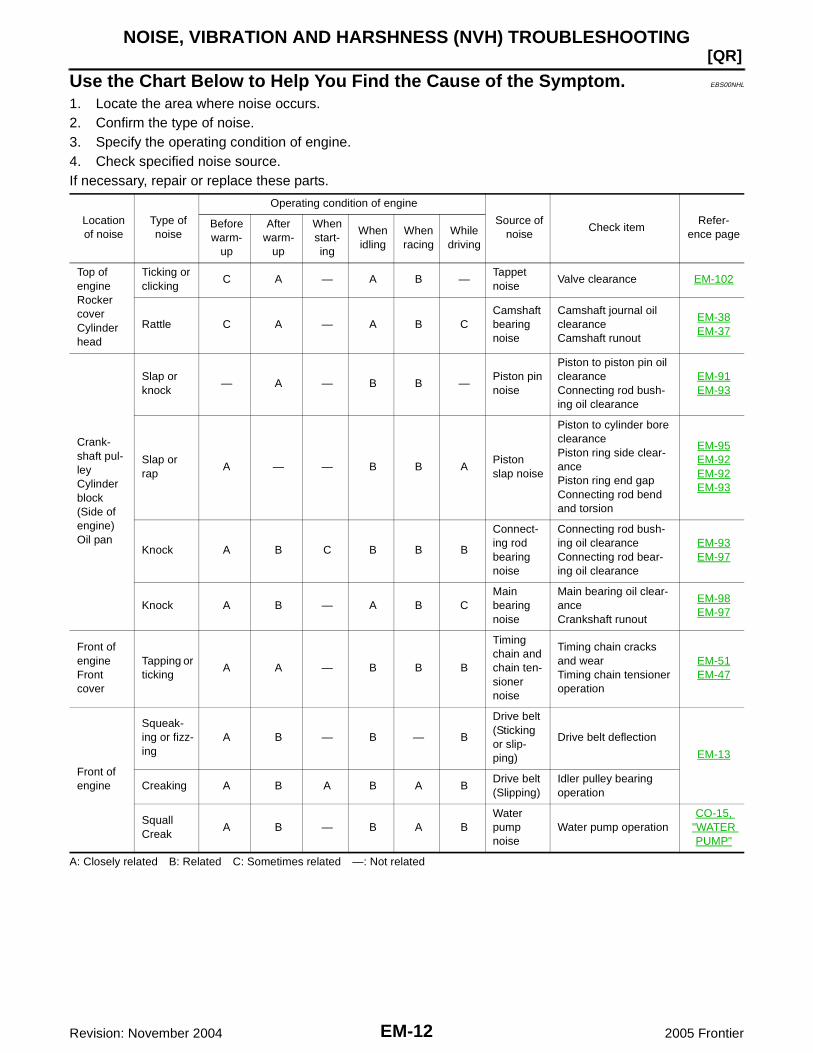
Use the Chart Below to Help You Find the Cause of the Symptom. EBS00NHL
1. Locate the area where noise occurs.2. Confirm the type of noise.3. Specify the operating condition of engine.4. Check specified noise source.If necessary, repair or replace these parts.
A: Closely related B: Related C: Sometimes related —: Not related
Locationof noise
Type ofnoise
Operating condition of engine
Source ofnoise
Check itemRefer-
ence pageBeforewarm-
up
Afterwarm-
up
Whenstart-ing
Whenidling
Whenracing
Whiledriving
Top ofengineRockercoverCylinderhead
Ticking orclicking
C A — A B —Tappetnoise
Valve clearance EM-102
Rattle C A — A B CCamshaftbearingnoise
Camshaft journal oilclearanceCamshaft runout
EM-38EM-37
Crank-shaft pul-leyCylinderblock(Side ofengine)Oil pan
Slap orknock
— A — B B —Piston pinnoise
Piston to piston pin oilclearanceConnecting rod bush-ing oil clearance
EM-91EM-93
Slap orrap
A — — B B APistonslap noise
Piston to cylinder boreclearancePiston ring side clear-ancePiston ring end gapConnecting rod bendand torsion
EM-95EM-92EM-92EM-93
Knock A B C B B B
Connect-ing rodbearingnoise
Connecting rod bush-ing oil clearanceConnecting rod bear-ing oil clearance
EM-93EM-97
Knock A B — A B CMainbearingnoise
Main bearing oil clear-anceCrankshaft runout
EM-98EM-97
Front ofengineFrontcover
Tapping orticking
A A — B B B
Timingchain andchain ten-sionernoise
Timing chain cracksand wearTiming chain tensioneroperation
EM-51EM-47
Front ofengine
Squeak-ing or fizz-ing
A B — B — B
Drive belt(Stickingor slip-ping)
Drive belt deflection
EM-13
Creaking A B A B A BDrive belt(Slipping)
Idler pulley bearingoperation
SquallCreak
A B — B A BWaterpumpnoise
Water pump operationCO-15,
"WATERPUMP"
DRIVE BELTS
EM-13
[QR]
C
D
E
F
G
H
I
J
K
L
M
A
EM
Revision: November 2004 2005 Frontier
DRIVE BELTS PFP:02117
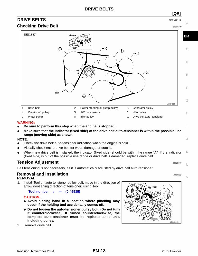
Checking Drive Belt EBS00NHM
WARNING:● Be sure to perform this step when the engine is stopped.● Make sure that the indicator (fixed side) of the drive belt auto-tensioner is within the possible use
range (moving side) as shown.NOTE:● Check the drive belt auto-tensioner indication when the engine is cold.● Visually check entire drive belt for wear, damage or cracks.● When new drive belt is installed, the indicator (fixed side) should be within the range "A". If the indicator
(fixed side) is out of the possible use range or drive belt is damaged, replace drive belt.
Tension Adjustment EBS00NHN
Belt tensioning is not necessary, as it is automatically adjusted by drive belt auto-tensioner.
Removal and Installation EBS00NIG
REMOVAL1. Install Tool on auto tensioner pulley bolt, move in the direction of
arrow (loosening direction of tensioner) using Tool.
CAUTION:● Avoid placing hand in a location where pinching may
occur if the holding tool accidentally comes off.● Do not loosen the auto-tensioner pulley bolt. (Do not turn
it counterclockwise.) If turned counterclockwise, thecomplete auto-tensioner must be replaced as a unit,including pulley.
2. Remove drive belt.
1. Drive belt 2. Power steering oil pump pulley 3. Generator pulley
4. Crankshaft pulley 5. A/C compressor 6. Idler pulley
7. Water pump 8. Idler pulley 9. Drive belt auto- tensioner
LBIA0438E
Tool number : — (J-46535)
LBIA0439E

EM-14Revision: November 2004
[QR]DRIVE BELTS
2005 Frontier
INSTALLATIONInstallation is in the reverse order of removal.CAUTION:● Do not loosen the auto-tensioner pulley bolt. (Do not turn it counterclockwise.) If turned counter-
clockwise, the complete auto-tensioner must be replaced as a unit, including pulley.● Avoid placing hand in a location where pinching may occur if the holding tool accidentally comes
off.● Confirm belts are completely set on the pulleys.● Check that there are no engine working fluids on the drive belt or pulley grooves.NOTE:● Turn crankshaft pulley clockwise several times to equalize tension between each pulley.● Confirm tension of drive belt indicator (fixed side) is within the possible use range.
Removal and Installation of Drive Belt Auto-Tensioner EBS00NHP
REMOVAL1. Remove air cleaner and air duct EM-15, "REMOVAL" .2. Remove drive belt. Refer to EM-13, "REMOVAL" .3. Remove the power steering oil pump and position aside. Refer to PS-21, "REMOVAL" .4. Remove generator. Refer to SC-37, "REMOVAL" .5. Remove drive belt auto-tensioner.
INSTALLATIONInstallation is in the reverse order of removal.CAUTION:If there is damage greater than peeled paint, replace drive belt auto-tensioner.
LBIA0440E

AIR CLEANER AND AIR DUCT
EM-15
[QR]
C
D
E
F
G
H
I
J
K
L
M
A
EM
Revision: November 2004 2005 Frontier
AIR CLEANER AND AIR DUCT PFP:16500
Removal and Installation EBS00NHR
REMOVAL1. Remove two bolts and remove air duct.
● Add mating marks as necessary for easier installation.2. Remove resonator in fender lifting left fender protector, as necessary.
INSPECTION AFTER REMOVALInspect air duct assembly for cracks or tear.● Replace air duct assembly, if necessary.
INSTALLATIONInstallation is in the reverse order of removal.● Align marks. Attach each joint. Screw clamps firmly.● Install duct to intake manifold by aligning "LOCK-UNLOCK" upward.
1. Air cleaner case 2. Air duct and resonator assembly 3. Air duct
4. Intake manifold 5. Air cleaner filter
LBIA0441E

EM-16Revision: November 2004
[QR]AIR CLEANER AND AIR DUCT
2005 Frontier
Changing Air Cleaner Filter EBS00NHS
REMOVAL1. Unfasten clips and lift up air cleaner case upper.2. Remove air cleaner filter.
INSTALLATIONInstallation is in the reverse order of removal.
LBIA0442E

INTAKE MANIFOLD
EM-17
[QR]
C
D
E
F
G
H
I
J
K
L
M
A
EM
Revision: November 2004 2005 Frontier
INTAKE MANIFOLD PFP:14003
Removal and Installation EBS00NHT
CAUTION:Do not remove or disassemble parts unless instructed as shown in the figure.
REMOVAL1. Release fuel pressure. Refer to EC-95, "FUEL PRESSURE RELEASE" .2. Remove air cleaner case, air cleaner and air duct.3. Disconnect water hoses from electric throttle control actuator, and pinch water hoses near electric throttle
control actuator to prevent engine coolant spilling.CAUTION:● Perform this step when engine is cold.● Do not spill engine coolant on drive belt.
1. Vacuum hose 2. Vacuum hose adapter 3. O–ring
4. Vacuum hose 5.EVAP canister purge volume controlsolenoid valve
6. Vacuum hose
7. Service port 8. Collar 9. Grommet
10. Intake manifold support 11. Vacuum hose 12. Gasket
13. Intake manifold 14. Fuel tube protector 15. Air cleaner
16. Air cleaner case 17. PCV hose 18. Gasket
19. PCV hose 20. Water hose 21. Water hose
22. Air duct 23. Electric throttle control actuator 24. Mass air flow sensor
WBIA0645E

EM-18Revision: November 2004
[QR]INTAKE MANIFOLD
2005 Frontier
4. Remove mass air flow sensor from intake manifold.CAUTION:Handle the mass air flow sensor with care:● Do not shock it.● Do not disassemble it.● Do not touch the internal sensor.
5. Remove quick connector cap, and disconnect quick connectorat the engine side. Refer to EM-28, "FUEL INJECTOR ANDFUEL TUBE" .
6. Remove electric throttle control actuator with the following procedure:a. Disconnect harness connector.b. Loosen bolts in reverse order as shown, and remove electric
throttle control actuator and gasket.CAUTION:● Handle carefully to avoid any shock to electric throttle
control actuator.● Do not disassemble.
7. Disconnect harness, vacuum hoses and PCV hoses from intake manifold, and move them aside.8. Remove intake manifold support.9. Loosen nuts and bolts in reverse order as shown, and remove
intake manifold, fuel tube protector and gasket.CAUTION:● Cover engine openings to avoid entry of foreign materi-
als.● Do not disassemble intake manifold.NOTE:Disregard No. 6 when loosening.
10. Remove EVAP canister purge volume control solenoid valve and vacuum hose adapter from intake mani-fold, if necessary.
11. Disconnect sub-harness from fuel injector. Refer to EM-28, "FUEL INJECTOR AND FUEL TUBE" .12. Remove fuel tube and fuel injector assembly from intake manifold. Refer to EM-28, "FUEL INJECTOR
AND FUEL TUBE" .
INSTALLATIONInstallation in the reverse order of removal.
Intake Manifold and Fuel Tube Protector● If stud bolts were removed, install them and tighten to the specified torque below.
LBIA0450E
PBIC2987E
PBIC2988E

INTAKE MANIFOLD
EM-19
[QR]
C
D
E
F
G
H
I
J
K
L
M
A
EM
Revision: November 2004 2005 Frontier
● Tighten in numerical order as shown.NOTE:No. 6 means double tightening of bolt No. 1.
Electric Throttle Control Actuator● Tighten bolts equally and diagonally in several steps and in
numerical order as shown.● Perform the “Throttle Valve Closed Position Learning” when har-
ness connector of electric throttle control actuator is discon-nected. Refer to EC-92, "Throttle Valve Closed PositionLearning" .
● Perform the “Idle Air Volume Learning” and “Throttle ValveClosed Position Learning” when electric throttle control actuatoris replaced. Refer to EC-93, "Idle Air Volume Learning" .
INSPECTION AFTER INSTALLATIONMake sure there are no fuel leaks at connections with the following procedure:1. Apply fuel pressure to fuel lines with turning ignition switch “ON” (with the engine stopped). Then make
sure there are no fuel leaks at connections.NOTE:Use mirrors for checking on invisible points.
2. Start the engine. With engine speed increased, make sure again there are no fuel leaks at connections.CAUTION:Do not touch the engine immediately after stopped as the engine becomes extremely hot.
Intake manifold bolts : 9.4 N·m (0.96 kg-m, 83in-lb)
Refer to the following for locating bolts and nuts.M8 x 38 mm (1.50 in) (Color green) : No. 1, 6M8 x 35 mm (1.38 in) : No. 2, 3Nut : No. 4, 5
PBIC2988E
PBIC2987E

EM-20Revision: November 2004
[QR]EXHAUST MANIFOLD AND THREE WAY CATALYST
2005 Frontier
EXHAUST MANIFOLD AND THREE WAY CATALYST PFP:14004
Removal and Installation EBS00NHU
REMOVAL1. Release fuel pressure. Refer to EC-708, "FUEL PRESSURE RELEASE" .2. Remove quick connector cap, and disconnect quick connector
at the engine side. Refer to EM-15, "AIR CLEANER AND AIRDUCT" .
3. Remove air duct, PCV hose (between air duct and rocker cover) and electric throttle control actuator.Refer to EM-17, "INTAKE MANIFOLD" .
4. Disconnect harness connector of air fuel ratio sensor 1, and harness from bracket and middle clamp.5. Remove air fuel ratio sensor 1 using Tool.
CAUTION:● Be careful not to damage air fuel ratio sensor 1.● Discard any air fuel ratio sensor 1 which has been dropped from a height of more than 0.5 m
(19.7 in) onto a hard surface such as a concrete floor; replace with a new one.
1. Air fuel ratio sensor 1 2. Exhaust manifold and three way catalyst assembly 3. Gasket
4. Bracket 5. Exhaust manifold cover
WBIA0647E
LBIA0450E
Tool number : KV10117100 (J-36471)

EXHAUST MANIFOLD AND THREE WAY CATALYST
EM-21
[QR]
C
D
E
F
G
H
I
J
K
L
M
A
EM
Revision: November 2004 2005 Frontier
6. Remove exhaust front tube. Refer to EX-5, "REMOVAL" .7. Remove exhaust manifold cover.8. Remove bracket between exhaust manifold–three way catalyst assembly and transmission assembly.9. Loosen nuts in reverse order as shown to remove exhaust man-
ifold and three way catalyst assembly.
10. Remove gasket.CAUTION:Cover engine openings to avoid entry of foreign materials.
INSPECTION AFTER REMOVALSurface Distortion● Using a straightedge and a feeler gauge, check the surface dis-
tortion of exhaust manifold and three way catalyst assemblymating surface.
● If it exceeds the limit, replace exhaust manifold and three waycatalyst assembly.
INSTALLATIONinstallation is in the reverse order of removal.
Exhaust Manifold1. If stud bolts were removed, install them and tighten to the specified torque below.
2. Tighten nuts in numerical order as shown.3. Tighten nuts in numerical order as shown again.
Air Fuel Ratio Sensor 1CAUTION:● Before installing new air fuel ratio sensor 1, clean exhaust system threads using a heated oxygen
sensor thread cleaner (commercial service tool: J-43897-18 or J-43897-12) and apply anti-seizelubricant (commercial service tool).
● Do not over torque air fuel ratio sensor 1. Doing so may cause damage to air fuel ratio sensor 1,resulting in the “MIL” coming on.
PBIC2990E
Limit : 0.3 mm (0.012 in)
PBIC2991E
Exhaust manifold stud bolt : 14.7 N·m (1.5 kg-m, 11 ft-lb)
PBIC2990E

EM-22Revision: November 2004
[QR]OIL PAN
2005 Frontier
OIL PAN PFP:11110
Removal and Installation EBS00NHV
REMOVALWARNING:To avoid the danger of being scalded, do not drain the engine oil when the engine is hot.1. Remove engine undercover.2. Drain engine oil. Refer to MA-25, "Changing Engine Oil" .
CAUTION:● Perform this step when the engine is cold.● Do not spill engine oil on drive belt.
3. Remove oil pan with the following procedure:a. Remove A/T fluid cooler tube (A/T models). Refer to AT-245, "TRANSMISSION ASSEMBLY" .b. Loosen bolts in reverse order as shown with power tool.
Remove A/T fluid cooler tube bracket (A/T models).
c. Insert the seal cutter [SST] between oil pan and cylinder block, and slide it by tapping on the side of thetool with a hammer. Remove oil pan.
1. Oil pan 2. A/T fluid cooler tube bracket (A/T models) 3. Drain plug
4. Drain plug washer
PBIC2992E
PBIC2993E

OIL PAN
EM-23
[QR]
C
D
E
F
G
H
I
J
K
L
M
A
EM
Revision: November 2004 2005 Frontier
CAUTION:● Be careful not to damage the mating surfaces.● Do not insert a screwdriver, this will damage the mating
surfaces.
INSTALLATION1. Install oil pan with the following procedure:a. Use a scraper to remove old liquid gasket from mating surfaces.
● Also remove the old liquid gasket from mating surface of cyl-inder block.
● Remove old liquid gasket from the bolt holes and threads.CAUTION:Do not scratch or damage the mating surfaces when clean-ing off old liquid gasket.
b. Apply a continuous bead of liquid gasket using Tool as shown.
Use Genuine RTV Silicone Sealant or equivalent. Refer toGI-45, "Recommended Chemical Products and Sealants" .CAUTION:Attaching should be done within 5 minutes after coating.
c. Tighten bolts in numerical order as shown.● Install A/T fluid cooler tube bracket with bolts No.1 and 9 as
shown (A/T models).
2. Install oil pan drain plug. Refer to MA-25, "Changing Engine Oil" .3. Install in the reverse order of removal after this step.
NOTE:Pour engine oil at least 30 minutes after oil pan is installed.
INSPECTION AFTER INSTALLATION1. Check the engine oil level, and adjust the level. Refer to LU-6, "ENGINE OIL LEVEL" .
Tool number : KV10111100 (J-37228)
WBIA0566E
PBIC2994E
Tool number : WS39930000 ( — )
PBIC2984E
PBIC2993E

EM-24Revision: November 2004
[QR]OIL PAN
2005 Frontier
2. Start the engine, and make sure there is no leaks of engine oil.3. Stop the engine and wait for 10 minutes.4. Check the engine oil level again. Refer to LU-6, "ENGINE OIL LEVEL" .

IGNITION COIL
EM-25
[QR]
C
D
E
F
G
H
I
J
K
L
M
A
EM
Revision: November 2004 2005 Frontier
IGNITION COIL PFP:22448
Removal and Installation EBS00NHW
REMOVAL1. Remove intake manifold (except for ignition coil No.1). Refer to EM-17, "INTAKE MANIFOLD" .2. Disconnect harness connector from ignition coil.3. Remove ignition coil.
CAUTION:Do not drop or shock it.
INSTALLATIONInstallation is in the reverse order of removal.
1. Ignition coil 2. Spark plug 3. Rocker cover
WBIA0648E
EM-26Revision: November 2004
[QR]SPARK PLUG (PLATINUM-TIPPED TYPE)
2005 Frontier
SPARK PLUG (PLATINUM-TIPPED TYPE) PFP:22401
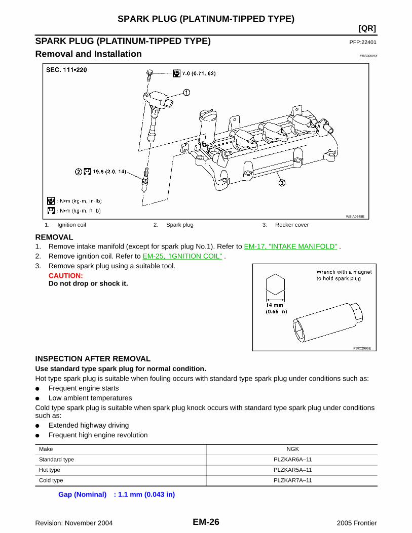
Removal and Installation EBS00NHX
REMOVAL1. Remove intake manifold (except for spark plug No.1). Refer to EM-17, "INTAKE MANIFOLD" .2. Remove ignition coil. Refer to EM-25, "IGNITION COIL" .3. Remove spark plug using a suitable tool.
CAUTION:Do not drop or shock it.
INSPECTION AFTER REMOVALUse standard type spark plug for normal condition.Hot type spark plug is suitable when fouling occurs with standard type spark plug under conditions such as:● Frequent engine starts● Low ambient temperaturesCold type spark plug is suitable when spark plug knock occurs with standard type spark plug under conditionssuch as:● Extended highway driving● Frequent high engine revolution
1. Ignition coil 2. Spark plug 3. Rocker cover
WBIA0648E
PBIC2996E
Make NGK
Standard type PLZKAR6A–11
Hot type PLZKAR5A–11
Cold type PLZKAR7A–11
Gap (Nominal) : 1.1 mm (0.043 in)

SPARK PLUG (PLATINUM-TIPPED TYPE)
EM-27
[QR]
C
D
E
F
G
H
I
J
K
L
M
A
EM
Revision: November 2004 2005 Frontier
CAUTION:● Do not drop or shock spark plug.● Do not use wire brush for cleaning.● If plug tip is covered with carbon, spark plug cleaner may
be used.
● Checking and adjusting plug gap is not required betweenchange intervals.
INSTALLATIONInstallation is in the reverse order of removal.
Cleaner air pressure:
Less than 588 kPa (6 kg/cm2 , 85 psi)Cleaning time:
Less than 20 seconds
SMA773C
SMA806CA

EM-28Revision: November 2004
[QR]FUEL INJECTOR AND FUEL TUBE
2005 Frontier
FUEL INJECTOR AND FUEL TUBE PFP:16600
Removal and Installation EBS00NHY
CAUTION:Do not remove or disassemble parts unless instructed as shown.
REMOVALWARNING:● Put a “CAUTION: INFLAMMABLE” sign in the workshop.● Be sure to work in a well ventilated area and furnish workshop with a CO2 fire extinguisher.● Do not smoke while servicing fuel system. Keep open flames and sparks away from the work area.1. Release fuel pressure. Refer to EC-708, "FUEL PRESSURE RELEASE" .
2. Remove quick connector cap (engine side).
1. Fuel feed hose 2. Quick connector cap (engine side) 3. Sub-harness
4. Fuel tube 5. O-ring (black) 6. Clip
7. Fuel injector 8. O-ring (green)
WBIA0649E
LBIA0450E
KBIA0701E

FUEL INJECTOR AND FUEL TUBE
EM-29
[QR]
C
D
E
F
G
H
I
J
K
L
M
A
EM
Revision: November 2004 2005 Frontier
3. With the sleeve side of quick connector release facing quick connector, install quick connector releaseonto fuel tube.
4. Insert quick connector release into quick connector until sleeve contacts and goes no further. Hold quickconnector release on that position.
CAUTION:Disconnect quick connector by using tool, not by pickingout retainer tabs.CAUTION:Inserting quick connector release hard will not disconnectquick connector. Hold quick connector release where itcontacts and goes no further.
5. Draw and pull out quick connector straight from fuel tube.CAUTION:● Pull quick connector holding “A” position in the figure.● Do not pull with lateral force applied. O-ring inside quick
connector may be damaged.● Prepare container and cloth beforehand as fuel will leak out.● Avoid fire and sparks.● Keep parts away from heat source. Especially, be careful when welding is performed around
them.● Do not expose parts to battery electrolyte or other acids.● Do not bend or twist connection between quick connector and fuel feed hose during installa-
tion/removal.● To keep clean the connecting portion and to avoid dam-
age and foreign materials, cover them completely withplastic bags or something similar.
6. Remove intake manifold. Refer to EM-17, "REMOVAL" .7. Disconnect sub-harness for fuel injector.8. Loosen bolts in reverse order as shown.9. Remove fuel tube and fuel injector assembly.
CAUTION:● When removing, be careful to avoid any interference with
fuel injector.● Use a shop cloth to absorb any fuel leaks from fuel tube.
Tool number : — (J-45488)
KBIA0702E
PBIC2205E
PBIC2998E

EM-30Revision: November 2004
[QR]FUEL INJECTOR AND FUEL TUBE
2005 Frontier
10. Remove fuel injector from fuel tube with the following procedure:a. Open and remove clip.b. Remove fuel injector from fuel tube by pulling straight.
CAUTION:● Be careful with remaining fuel that may go out from fuel
tube.● Be careful not to damage fuel injector nozzle during
removal.● Do not bump or drop fuel injector.● Do not disassemble fuel injector.
INSTALLATION1. Note the following, and install O-rings to fuel injector.
CAUTION:● Upper and lower O-rings are different. Be careful not to confuse them.
● Handle O-ring with bare hands. Do not wear gloves.● Lubricate O-ring with new engine oil.● Do not clean O-ring with solvent.● Make sure that O-ring and its mating part are free of foreign material.● When installing O-ring, be careful not to scratch it with tool or fingernails. Also be careful not to
twist or stretch O-ring. If O-ring was stretched while it was being attached, do not insert itquickly into fuel tube.
PBIC2999E
Fuel tube side : BlackNozzle side : Green

FUEL INJECTOR AND FUEL TUBE
EM-31
[QR]
C
D
E
F
G
H
I
J
K
L
M
A
EM
Revision: November 2004 2005 Frontier
● Insert O-ring straight into fuel tube. Do not decenter ortwist it.
2. Insert clip into clip attachment groove on fuel injector.CAUTION:● Do not reuse clip. Replace it with a new one.● Be careful to keep clip from interfering with O-ring. If
interference occurs, replace O-ring.3. Insert fuel injector into fuel tube with clip attached.
● Insert it while matching it to the axial center.● Insert fuel injector so that protrusion of fuel tube matches cut-
out of clip.● Make sure that fuel tube flange is securely fixed in flange fix-
ing groove on clip.4. Make sure that installation is complete by checking that fuel
injector does not rotate or come off.
5. Install fuel tube and fuel injector assembly with the following procedure:CAUTION:When installing, be careful to avoid any interference with fuel injector.
a. Insert the tip of each fuel injector into intake manifold.b. Tighten bolts evenly in two steps in numerical order as shown.
6. Connect sub-harness for fuel injector.7. Install intake manifold. Refer to EM-18, "INSTALLATION" .8. Note the following, and connect quick connector at the engine side to install fuel feed hose.a. Check the connection for foreign material and damage.b. Align center to insert quick connector straightly into fuel tube.
NOTE:The figure shows the engine side as an example.● Insert quick connector to fuel tube until the top spool on fuel
tube is inserted completely and the second level spool is posi-tioned slightly below quick connector bottom end.CAUTION:● Hold “A” position in the figure when inserting fuel tube
into quick connector.● Carefully align center to avoid inclined insertion to pre-
vent damage to O-ring inside quick connector.● Insert until you hear a “click” sound and actually feel the engagement.
PBIC3000E
Fuel tube bolts1st step : 12.8 N·m (1.3 kg-m, 9 ft-lb)2nd step : 28.0 N·m (2.9 kg-m, 21 ft-lb)
PBIC2998E
KBIA0272E

EM-32Revision: November 2004
[QR]FUEL INJECTOR AND FUEL TUBE
2005 Frontier
● To avoid misidentification of engagement with a similar sound, be sure to perform the nextstep.
c. Before clamping fuel feed hose with hose clamps, pull quick connector hard by hand holding “A” position.Make sure it is completely engaged (connected) so that it does not come out from fuel feed tube.
d. Install quick connector cap to quick connector connection.(engine side)● Install so that the arrow mark on the side faces up.CAUTION:● Make sure that quick connector and fuel tube are
securely fit into quick connector cap installation groove.● If quick connector cap cannot be installed smoothly,
quick connector may have not been installed correctly.Check the connection again.
9. Install fuel feed hose to hose clamp.10. Installation is in the reverse order of removal after this step.
INSPECTION AFTER INSTALLATIONCheck on Fuel Leaks1. Apply fuel pressure to fuel lines with turning ignition switch “ON” (with the engine stopped). Then make
sure there are no fuel leaks at connections.NOTE:Use mirrors for checking on invisible points.
2. Start the engine. With engine speed increased, make sure again there are no fuel leaks at connections.CAUTION:Do not touch the engine immediately after stopped as the engine becomes extremely hot.
PBIC2348E
ROCKER COVER
EM-33
[QR]
C
D
E
F
G
H
I
J
K
L
M
A
EM
Revision: November 2004 2005 Frontier
ROCKER COVER PFP:13264
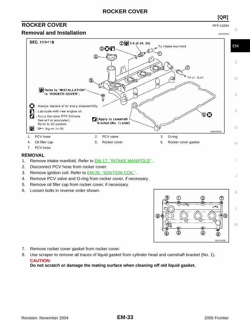
Removal and Installation EBS00NHZ
REMOVAL1. Remove intake manifold. Refer to EM-17, "INTAKE MANIFOLD" .2. Disconnect PCV hose from rocker cover.3. Remove ignition coil. Refer to EM-25, "IGNITION COIL" .4. Remove PCV valve and O-ring from rocker cover, if necessary.5. Remove oil filler cap from rocker cover, if necessary.6. Loosen bolts in reverse order shown.
7. Remove rocker cover gasket from rocker cover.8. Use scraper to remove all traces of liquid gasket from cylinder head and camshaft bracket (No. 1).
CAUTION:Do not scratch or damage the mating surface when cleaning off old liquid gasket.
1. PCV hose 2. PCV valve 3. O-ring
4. Oil filler cap 5. Rocker cover 6. Rocker cover gasket
7. PCV hose
WBIA0650E
PBIC3003E

EM-34Revision: November 2004
[QR]ROCKER COVER
2005 Frontier
INSTALLATION1. Apply liquid gasket to the position shown with the following pro-
cedure:a. Refer to figure “a” to apply liquid gasket to joint part of camshaft
bracket (No. 1) and cylinder head.b. Refer to figure “b” to apply liquid gasket in 90° to figure “a”.
Use Genuine RTV Silicone Sealant or equivalent. Refer toGI-45, "Recommended Chemical Products and Sealants" .
2. Install new rocker cover gasket to rocker cover.3. Install rocker cover.
● Check if rocker cover gasket is not dropped from the installation groove of rocker cover.4. Tighten bolts in two steps separately in numerical order as shown.
5. Installation of the remaining components is in the reverse order of removal.
PBIC2635E
Rocker cover bolts1st step : 2.0 N·m (0.2 kg-m, 18 in-lb)
2nd step : 8.3 N·m (0.85 kg-m, 73 in-lb)

CAMSHAFT
EM-35
[QR]
C
D
E
F
G
H
I
J
K
L
M
A
EM
Revision: November 2004 2005 Frontier
CAMSHAFT PFP:13001
Removal and Installation EBS00NI0
NOTE:This section describes removal/installation procedure of camshaft without removing front cover. If front coveris removed or installed, refer to EM-47, "TIMING CHAIN" .
REMOVAL1. Remove the rocker cover. Refer to EM-33, "REMOVAL" .2. Remove the drive belt. Refer to EM-13, "REMOVAL" .3. Disconnect and remove the camshaft position sensor (PHASE).4. Disconnect the IVT control solenoid electrical connector.5. Disconnect the ground electrical connections from the front cover.
1. Camshaft bracket (No. 2 to 5) 2. Seal washer 3. Camshaft bracket (No. 1)
4. Front cover 5. Chain guide 6. Chain tensioner
7. Spring 8. Chain tensioner plunger 9. O-ring
10. Oil ring 11. O-ring 12.Intake valve timing control solenoidvalve
13. Intake valve timing control cover 14. Camshaft sprocket (INT) 15. Camshaft sprocket (EXH)
16. O-ring 17. Valve lifter 18. Camshaft (INT)
19. Camshaft (EXH) 20. O-ring 21. Camshaft position sensor (PHASE)
WBIA0651E
EM-36Revision: November 2004
[QR]CAMSHAFT
2005 Frontier
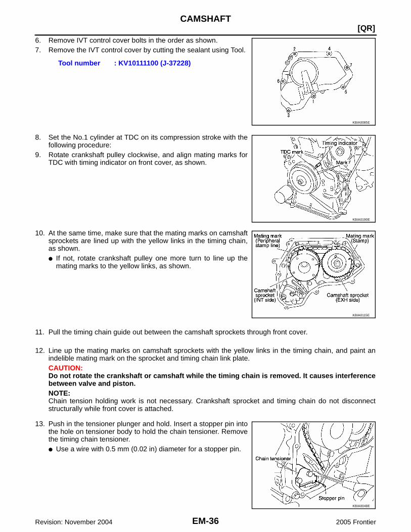
6. Remove IVT control cover bolts in the order as shown.7. Remove the IVT control cover by cutting the sealant using Tool.
8. Set the No.1 cylinder at TDC on its compression stroke with thefollowing procedure:
9. Rotate crankshaft pulley clockwise, and align mating marks forTDC with timing indicator on front cover, as shown.
10. At the same time, make sure that the mating marks on camshaftsprockets are lined up with the yellow links in the timing chain,as shown.● If not, rotate crankshaft pulley one more turn to line up the
mating marks to the yellow links, as shown.
11. Pull the timing chain guide out between the camshaft sprockets through front cover.
12. Line up the mating marks on camshaft sprockets with the yellow links in the timing chain, and paint anindelible mating mark on the sprocket and timing chain link plate.CAUTION:Do not rotate the crankshaft or camshaft while the timing chain is removed. It causes interferencebetween valve and piston.NOTE:Chain tension holding work is not necessary. Crankshaft sprocket and timing chain do not disconnectstructurally while front cover is attached.
13. Push in the tensioner plunger and hold. Insert a stopper pin intothe hole on tensioner body to hold the chain tensioner. Removethe timing chain tensioner.● Use a wire with 0.5 mm (0.02 in) diameter for a stopper pin.
Tool number : KV10111100 (J-37228)
KBIA0085E
KBIA0190E
KBIA0115E
KBIA0048E

CAMSHAFT
EM-37
[QR]
C
D
E
F
G
H
I
J
K
L
M
A
EM
Revision: November 2004 2005 Frontier
14. Secure the hexagonal part of camshaft with a suitable tool.Loosen the camshaft sprocket bolts and remove the camshaftsprockets.
15. Loosen the camshaft bracket bolts in the order as shown, andremove the camshaft brackets and camshafts.● Remove No.1 camshaft bracket by slightly tapping it with a
rubber mallet.● Note positions, and set them aside in the order removed.
16. Remove the valve lifters.● Note positions, and set them aside in the order removed.
INSPECTION AFTER REMOVALCamshaft Runout1. Put V-block on a precise flat table, and support No. 2 and 5 jour-
nals of camshaft.CAUTION:Do not support No. 1 journal (on the side of camshaftsprocket) because it has a different diameter from the otherfour locations.
2. Set a dial indicator vertically to No. 3 journal.3. Turn camshaft to one direction with hands, and measure the
camshaft runout on the dial indicator. (Total indicator reading)
4. If out of the standard, replace camshaft.
Camshaft Cam Height1. Measure the camshaft cam height with a micrometer.
2. If wear is beyond the limit, replace camshaft.
KBIA0049E
WBIA0028E
Standard: Less than 0.02 mm (0.0008 in). PBIC2499E
Standard:Intake : 45.015 - 45.205 mm (1.7722 - 1.7797 in)Exhaust : 43.975 - 44.165 mm (1.7313 - 1.7388 in)
Cam wear limit: 0.2 mm (0.008 in)
PBIC0039E

EM-38Revision: November 2004
[QR]CAMSHAFT
2005 Frontier
Camshaft Journal Oil ClearanceCAMSHAFT JOURNAL DIAMETERMeasure the outer diameter of camshaft journal with a micrometer.
CAMSHAFT BRACKET INNER DIAMETER● Tighten camshaft bracket bolts with the specified torque. Refer to EM-40, "INSTALLATION" for the tight-
ening procedure.● Measure inner diameter “A” of camshaft bracket with a bore
gauge.
CAMSHAFT JOURNAL OIL CLEARANCE● (Oil clearance) = (Camshaft bracket inner diameter) – (Camshaft journal diameter)
● If out of the standard, replace either or both camshaft and cylinder head.NOTE:Camshaft brackets cannot be replaced as single parts, because they are machined together with cylinderhead. Replace whole cylinder head assembly.
Camshaft End Play1. Install camshaft in cylinder head. Refer to EM-40, "INSTALLATION" for tightening procedure.2. Install a dial indicator in thrust direction on front end of camshaft.
Measure the camshaft end play on the dial indicator when cam-shaft is moved forward/backward (in direction to axis).
Standard:No. 1 : 27.935 - 27.955 mm (1.0998 - 1.1006 in)No. 2, 3, 4, 5 : 23.435 - 23.455 mm (0.9226 - 0.9234 in)
PBIC0040E
Standard:No. 1 : 28.000 - 28.021 mm (1.1024 - 1.1032 in)No. 2, 3, 4, 5 : 23.500 - 23.521 mm (0.9252 - 0.9260 in)
PBIC1645E
Standard : 0.045 - 0.086 mm (0.0018 - 0.0034 in)
Standard : 0.115 - 0.188 mm (0.0045 - 0.0074 in)
PBIC2446E

CAMSHAFT
EM-39
[QR]
C
D
E
F
G
H
I
J
K
L
M
A
EM
Revision: November 2004 2005 Frontier
● Measure the following parts if out of the standard.– Dimension “A” for camshaft No. 1 journal
– Dimension “B” for cylinder head No. 1 journal bearing
● Refer to the standards above, and then replace camshaft and/or cylinder head.
Camshaft Sprocket Runout1. Put V-block on precise flat table, and support No. 2 and 5 journals of camshaft.
CAUTION:Do not support No. 1 journal (on the side of camshaft sprocket) because it has a different diameterfrom the other four locations.
2. Measure the camshaft sprocket runout with a dial indicator.(Total indicator reading)
● If it exceeds the limit, replace camshaft sprocket.
Valve LifterCheck if surface of valve lifter has any wear or cracks.● If anything above is found, replace valve lifter. Refer to EM-102,
"Valve Clearance" .
Standard : 25.800 - 25.848 mm (1.0157 - 1.0176 in)
Standard : 25.660 - 25.685 mm (1.0102 - 1.0112 in)
KBIA2426J
Limit : 0.15 mm (0.0059 in)
PBIC0930E
KBIA0182E

EM-40Revision: November 2004
[QR]CAMSHAFT
2005 Frontier
Valve Lifter ClearanceVALVE LIFTER OUTER DIAMETER● Measure the outer diameter of valve lifter with a micrometer.
VALVE LIFTER HOLE DIAMETERMeasure the diameter of valve lifter hole of cylinder head with aninside micrometer.
VALVE LIFTER CLEARANCE● (Valve lifter clearance) = (Valve lifter hole diameter) – (Valve lifter outer diameter)
● If out of the standard, referring to the each standard of valve lifter outer diameter and valve lifter holediameter, replace either or both valve lifter and cylinder head.
INSTALLATION1. Install valve lifters.
● Install them in the original positions.2. Install camshafts.
● Distinction between intake and exhaust camshafts is per-formed with the different shapes of rear end.
Standard : 33.965 - 33.980 mm (1.3372 - 1.3378 in)
JEM798G
Standard : 34.000 - 34.021 mm (1.3386 - 1.3394 in)
PBIC0043E
Standard : 0.020 - 0.056 mm (0.0008 - 0.0022 in)
Intake : Signal plate shape for camshaft posi-tion sensor (PHASE)
Exhaust : Cone end shape
KBIA0246E

CAMSHAFT
EM-41
[QR]
C
D
E
F
G
H
I
J
K
L
M
A
EM
Revision: November 2004 2005 Frontier
● Install camshafts so that camshaft dowel pins on the front sideare positioned as shown.
3. Install camshaft brackets with the following procedure:a. Remove foreign material completely from camshaft bracket backside and from cylinder head installation
face.b. Install camshaft brackets (No. 2 to 5) aligning the identification
marks on upper surface as shown.NOTE:Install so that identification mark can be correctly read whenviewed from the exhaust side.
c. Install camshaft bracket (No. 1) with the following procedure:i. Apply liquid gasket to camshaft bracket (No. 1) as shown.
Use Genuine RTV Silicone Sealant or equivalent. Refer toGI-45, "Recommended Chemical Products and Sealants" .CAUTION:After installation, be sure to wipe off any excessive liquidgasket leaking from part “A”.
ii. Apply liquid gasket to camshaft bracket (No. 1) contact surfaceon the front cover backside.Use Genuine RTV Silicone Sealant or equivalent. Refer toGI-45, "Recommended Chemical Products and Sealants" .● Apply liquid gasket to the outside of bolt hole on front cover.
KBIA0051E
SBIA0256E
PBIC2579E
SBIA0258E

EM-42Revision: November 2004
[QR]CAMSHAFT
2005 Frontier
iii. Locate camshaft bracket (No. 1) near installation position, andinstall it without disturbing the liquid gasket applied to the sur-faces.
4. Tighten bolts of camshaft brackets in the following steps, in numerical order as shown.
CAUTION:After tightening bolts of camshaft brackets, be sure to wipe offexcessive liquid gasket from the parts.5. Install camshaft position sensor (PHASE).6. Install camshaft sprockets.
● Install them by aligning the mating marks on each camshaftsprocket with the paint marks on the timing chain link platesduring removal.CAUTION:● Aligned mating marks could slip. Therefore, after
matching them, hold the timing chain in place by hand.● Before and after installing chain tensioner, make sure
again that mating marks have not slipped.NOTE:Before installation of chain tensioner, it is possible to re-matchthe marks on timing chain with the ones on each sprocket.
7. Install chain tensioner.CAUTION:After installation, pull the stopper pin off completely, and make sure that chain tensioner plungeris released.
8. Install chain guide.9. Install oil rings to the camshaft sprocket (INT) insertion points on backside of intake valve timing control
cover.10. Install O-ring to front cover.11. Apply liquid gasket using Tool to intake valve timing control
cover as shown.
Use Genuine RTV Silicone Sealant or equivalent. Refer toGI-45, "Recommended Chemical Products and Sealants" .
PBIC2746E
Step 1 (bolts 9 - 11) : 2.0 N·m (0.2 kg-m, 17 in-lb)Step 2 (bolts 1 - 8) : 2.0 N·m (0.2 kg-m, 17 in-lb)Step 3 (bolts 1 - 11) : 5.9 N·m (0.6 kg-m, 52 in-lb)Step 4 (bolts 1 - 11) : 10.4 N·m (1.1 kg-m, 92 in-lb)
Tool number : WS39930000 ( — )
SBIA0255E
PBIC2351E
SBIA0260E
CAMSHAFT
EM-43
[QR]
C
D
E
F
G
H
I
J
K
L
M
A
EM
Revision: November 2004 2005 Frontier
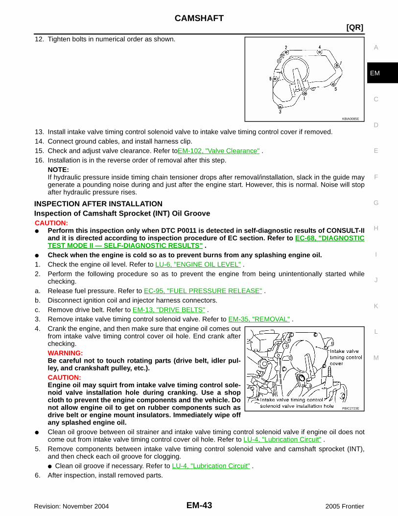
12. Tighten bolts in numerical order as shown.
13. Install intake valve timing control solenoid valve to intake valve timing control cover if removed.14. Connect ground cables, and install harness clip.15. Check and adjust valve clearance. Refer toEM-102, "Valve Clearance" .16. Installation is in the reverse order of removal after this step.
NOTE:If hydraulic pressure inside timing chain tensioner drops after removal/installation, slack in the guide maygenerate a pounding noise during and just after the engine start. However, this is normal. Noise will stopafter hydraulic pressure rises.
INSPECTION AFTER INSTALLATIONInspection of Camshaft Sprocket (INT) Oil GrooveCAUTION:● Perform this inspection only when DTC P0011 is detected in self-diagnostic results of CONSULT-II
and it is directed according to inspection procedure of EC section. Refer to EC-68, "DIAGNOSTICTEST MODE II — SELF-DIAGNOSTIC RESULTS" .
● Check when the engine is cold so as to prevent burns from any splashing engine oil.1. Check the engine oil level. Refer to LU-6, "ENGINE OIL LEVEL" .2. Perform the following procedure so as to prevent the engine from being unintentionally started while
checking.a. Release fuel pressure. Refer to EC-95, "FUEL PRESSURE RELEASE" .b. Disconnect ignition coil and injector harness connectors.c. Remove drive belt. Refer to EM-13, "DRIVE BELTS" .3. Remove intake valve timing control solenoid valve. Refer to EM-35, "REMOVAL" .4. Crank the engine, and then make sure that engine oil comes out
from intake valve timing control cover oil hole. End crank afterchecking.WARNING:Be careful not to touch rotating parts (drive belt, idler pul-ley, and crankshaft pulley, etc.).CAUTION:Engine oil may squirt from intake valve timing control sole-noid valve installation hole during cranking. Use a shopcloth to prevent the engine components and the vehicle. Donot allow engine oil to get on rubber components such asdrive belt or engine mount insulators. Immediately wipe offany splashed engine oil.
● Clean oil groove between oil strainer and intake valve timing control solenoid valve if engine oil does notcome out from intake valve timing control cover oil hole. Refer to LU-4, "Lubrication Circuit" .
5. Remove components between intake valve timing control solenoid valve and camshaft sprocket (INT),and then check each oil groove for clogging.● Clean oil groove if necessary. Refer to LU-4, "Lubrication Circuit" .
6. After inspection, install removed parts.
KBIA0085E
PBIC2723E

EM-44Revision: November 2004
[QR]CAMSHAFT
2005 Frontier
Valve Clearance EBS00NI1
INSPECTIONPerform inspection as follows after removal, installation or replacement of camshaft or valve-related parts, or ifthere is unusual engine conditions regarding valve clearance.1. Remove rocker cover. Refer to EM-33, "REMOVAL" .2. Remove undercover.3. Remove radiator shroud (lower). Refer to CO-11, "REMOVAL" .4. Measure the valve clearance with the following procedure:a. Set No. 1 cylinder at TDC of its compression stroke.
● Rotate crankshaft pulley clockwise and align TDC mark totiming indicator on front cover.
● At the same time, make sure that both intake and exhaustcam noses of No. 1 cylinder face outside as shown.
● If they do not face outside, rotate crankshaft pulley once more(360° degrees) and align as shown.
b. Use a feeler gauge, measure the clearance between valve lifterand camshaft.
Valve clearance:Unit: mm (in)
*:Approximately 80°C (176°F)
PBIC3015E
KBIA0400J
SEM139D
Cold Hot * (reference data)
Intake 0.24 - 0.32 (0.009 - 0.013) 0.304 - 0.416 (0.012 - 0.016)
Exhaust 0.26 - 0.34 (0.010 - 0.013) 0.308 - 0.432 (0.012 - 0.017)

CAMSHAFT
EM-45
[QR]
C
D
E
F
G
H
I
J
K
L
M
A
EM
Revision: November 2004 2005 Frontier
● By referring to the figure, measure the valve clearances atlocations marked “×” as shown in the table below (locationsindicated with black arrow in the figure) with a feeler gauge.
● No. 1 cylinder compression TDC
c. Rotate crankshaft pulley one revolution (360° degrees) and alignTDC mark to timing indicator on front cover.
● By referring to the figure, measure the valve clearance atlocations marked “×” as shown in the table below (locationsindicated with black arrow in the figure) with a feeler gauge.
● No. 4 cylinder compression TDC
5. If out of standard, perform adjustment. Refer to EM-45, "ADJUSTMENT" .
ADJUSTMENT● Perform adjustment depending on selected head thickness of valve lifter.1. Remove camshaft. Refer to EM-35, "REMOVAL" .2. Remove valve lifters at the locations that are out of the standard.3. Measure the center thickness of the removed valve lifters with a
micrometer.
4. Use the equation below to calculate valve lifter thickness for replacement.
Measuring position No. 1 CYL. No. 2 CYL. No. 3 CYL. No. 4 CYL.
No. 1 cylinder atcompression TDC
INT × ×
EXH × ×
PBIC3017E
PBIC3015E
Measuring position No. 1 CYL. No. 2 CYL. No. 3 CYL. No. 4 CYL.
No. 4 cylinder atcompression TDC
INT × ×
EXH × ×
PBIC3026E
KBIA0057E
Valve lifter thickness calculation: t = t1 + (C1 – C2 )t = Valve lifter thickness to be replacedt1 = Removed valve lifter thickness
EM-46Revision: November 2004
[QR]CAMSHAFT
2005 Frontier
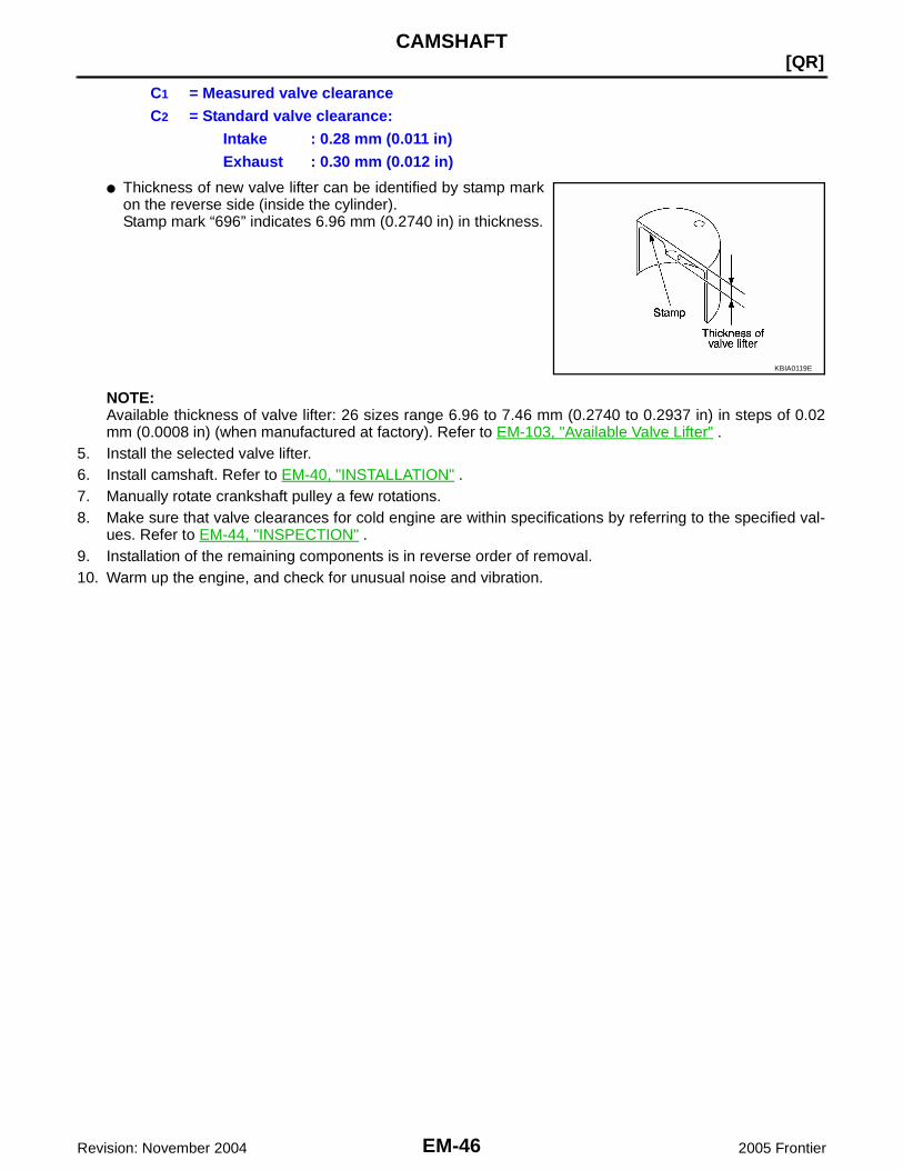
● Thickness of new valve lifter can be identified by stamp markon the reverse side (inside the cylinder).Stamp mark “696” indicates 6.96 mm (0.2740 in) in thickness.
NOTE:Available thickness of valve lifter: 26 sizes range 6.96 to 7.46 mm (0.2740 to 0.2937 in) in steps of 0.02mm (0.0008 in) (when manufactured at factory). Refer to EM-103, "Available Valve Lifter" .
5. Install the selected valve lifter.6. Install camshaft. Refer to EM-40, "INSTALLATION" .7. Manually rotate crankshaft pulley a few rotations.8. Make sure that valve clearances for cold engine are within specifications by referring to the specified val-
ues. Refer to EM-44, "INSPECTION" .9. Installation of the remaining components is in reverse order of removal.10. Warm up the engine, and check for unusual noise and vibration.
C1 = Measured valve clearanceC2 = Standard valve clearance:
Intake : 0.28 mm (0.011 in)Exhaust : 0.30 mm (0.012 in)
KBIA0119E

TIMING CHAIN
EM-47
[QR]
C
D
E
F
G
H
I
J
K
L
M
A
EM
Revision: November 2004 2005 Frontier
TIMING CHAIN PFP:13028
Removal and Installation EBS00NI2
1. O-ring 2. Camshaft sprocket (INT) 3. Camshaft sprocket (EXH)
4. Chain tensioner 5. Spring 6. Chain tensioner plunger
7. Timing chain slack guide 8. Timing chain 9. Front cover
10. Chain guide 11.Intake valve timing control solenoidvalve
12. Intake valve timing control cover
13. Oil ring 14. Front oil seal 15. Crankshaft pulley
16. Crankshaft pulley bolt 17. Crankshaft sprocket 18. Spacer
19. Balancer unit timing chain tensioner 20. Timing chain tension guide 21. Balancer unit
22. Balancer unit sprocket 23. Balancer unit timing chain
WBIA0652E

EM-48Revision: November 2004
[QR]TIMING CHAIN
2005 Frontier
REMOVAL1. Release the fuel pressure. Refer to EC-95, "FUEL PRESSURE RELEASE" .2. Remove the air cleaner and air duct assembly. Refer to EM-15, "REMOVAL" .3. Remove the spark plugs. Refer to EM-26, "REMOVAL" .4. Remove the rocker cover. Refer toEM-33, "REMOVAL" .5. Remove the coolant overflow reservoir tank.6. Remove the auxiliary drive belt auto-tensioner. Refer to EM-14, "REMOVAL" .7. Remove the generator. Refer to SC-37, "REMOVAL" .8. Remove the strut tower brace. Refer to FSU-5, "Components" .9. Dismount and position aside the A/C compressor with the piping attached.10. Dismount and position aside the power steering pump and reservoir tank with the piping attached.11. Remove the upper and lower oil pan, and oil strainer. Refer to EM-22, "REMOVAL" .12. Remove IVT control cover bolts in the order as shown.13. Remove the IVT control cover by cutting the sealant using Tool.
14. Pull chain guide between camshaft sprockets out through frontcover.
15. Set the No.1 cylinder at TDC on the compression stroke with thefollowing procedure:
a. Rotate the crankshaft pulley clockwise and align the matingmarks to the timing indicator on the front cover.
b. At the same time, make sure that the mating marks on the cam-shaft sprockets are lined up as shown.
● If not lined up, rotate the crankshaft pulley one more turn to lineup the mating marks to the positions as shown.
Tool number : KV10111100 (J-37228)
KBIA0085E
KBIA0190E
KBIA0115E
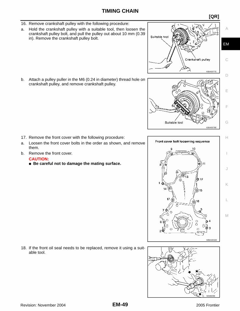
TIMING CHAIN
EM-49
[QR]
C
D
E
F
G
H
I
J
K
L
M
A
EM
Revision: November 2004 2005 Frontier
16. Remove crankshaft pulley with the following procedure:a. Hold the crankshaft pulley with a suitable tool, then loosen the
crankshaft pulley bolt, and pull the pulley out about 10 mm (0.39in). Remove the crankshaft pulley bolt.
b. Attach a pulley puller in the M6 (0.24 in diameter) thread hole oncrankshaft pulley, and remove crankshaft pulley.
17. Remove the front cover with the following procedure:a. Loosen the front cover bolts in the order as shown, and remove
them.b. Remove the front cover.
CAUTION:● Be careful not to damage the mating surface.
18. If the front oil seal needs to be replaced, remove it using a suit-able tool.
KBIA0077E
KBIA0078E
WBIA0032E
SEM829E

EM-50Revision: November 2004
[QR]TIMING CHAIN
2005 Frontier
19. Remove timing chain with the following procedure:a. Push in chain tensioner plunger. Insert a stopper pin into hole on chain tensioner body to secure chain
tensioner plunger and remove chain tensioner.NOTE:Use approximately 0.5 mm (0.02 in) dia. hard metal pin as astopper pin.
b. Remove timing chain.CAUTION:Do not rotate crankshaft or camshaft while timing chain is removed. It causes interferencebetween valve and piston.
20. Remove camshaft sprockets. Refer to EM-35, "CAMSHAFT" .21. Remove timing chain slack guide, timing chain tension guide and spacer.
22. Remove balancer unit timing chain tensioner with the following procedure:a. Lift lever up, and release ratchet claw for return proof.b. Push tensioner sleeve in, and hold it.c. Matching the hole on lever with the one on body, insert a stopper
pin to secure tensioner sleeve.NOTE:Use approximately 1 mm (0.04 in) dia. hard metal pin as a stop-per pin.
d. Remove balancer unit timing chain tensioner.
23. Secure the hexagonal portion of the balancer shaft using a suitable tool. Loosen the balancer unitsprocket bolt.
24. Remove balancer unit timing chain, balancer unit sprocket and crankshaft sprocket.NOTE:When removing balancer unit timing chain, remove crankshaft sprocket and balancer unit sprocket at thesame time.25. Loosen mounting bolts in reverse order as shown, and remove
balancer unit.CAUTION:Do not disassemble balancer unit.NOTE:Use TORX socket (size E14) for bolts No.1 to 4.
KBIA0048E
PBIC3027E
PBIC3028E
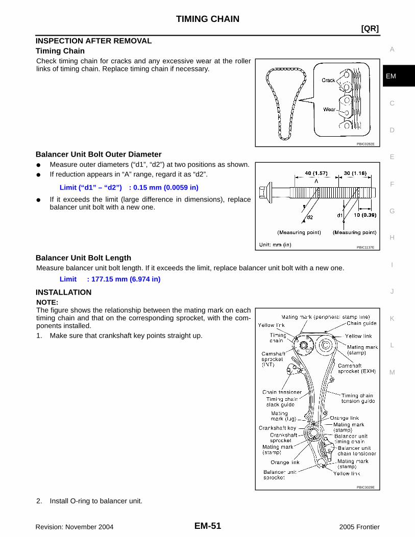
TIMING CHAIN
EM-51
[QR]
C
D
E
F
G
H
I
J
K
L
M
A
EM
Revision: November 2004 2005 Frontier
INSPECTION AFTER REMOVALTiming ChainCheck timing chain for cracks and any excessive wear at the rollerlinks of timing chain. Replace timing chain if necessary.
Balancer Unit Bolt Outer Diameter● Measure outer diameters (“d1”, “d2”) at two positions as shown.● If reduction appears in “A” range, regard it as “d2”.
● If it exceeds the limit (large difference in dimensions), replacebalancer unit bolt with a new one.
Balancer Unit Bolt LengthMeasure balancer unit bolt length. If it exceeds the limit, replace balancer unit bolt with a new one.
INSTALLATIONNOTE:The figure shows the relationship between the mating mark on eachtiming chain and that on the corresponding sprocket, with the com-ponents installed.1. Make sure that crankshaft key points straight up.
2. Install O-ring to balancer unit.
PBIC0282E
Limit (“d1” – “d2”) : 0.15 mm (0.0059 in)
PBIC1137E
Limit : 177.15 mm (6.974 in)
PBIC3029E

EM-52Revision: November 2004
[QR]TIMING CHAIN
2005 Frontier
3. Tighten bolts in numerical order as shown with the following pro-cedure to install balancer unit, using Tool.
CAUTION:If bolts are re-used, check their outer diameter before instal-lation. Refer to EM-51, "Balancer Unit Bolt Outer Diameter" .CAUTION:● Check tightening angle using Tool or a protractor. Do not
make judgment by visual check alone.● In step 3, loosen bolts in reverse order as shown.NOTE:Apply new engine oil to threads and seat surfaces of bolts.
4. Install crankshaft sprocket, balancer unit sprocket and balancerunit timing chain.● Make sure that crankshaft sprocket is positioned with mating
marks on cylinder block and crankshaft sprocket meeting atthe top.
● Install it by aligning mating marks on each sprocket and bal-ancer unit timing chain.
● Secure the hexagonal portion of the balancer shaft using asuitable tool. Tighten the balancer unit sprocket bolt to thespecified torque.
NOTE:Install crankshaft sprocket, balancer unit sprocket and balancer unit timing chain at the same time.
5. Install balancer unit timing chain tensioner.● After installation, make sure the mating marks have not
slipped, then remove stopper pin and release tensionersleeve.
Tool number : KV10112100 (BT8653-A)
Balancer bolt torqueStep 1 bolts 1 - 4 : 48.1 N·m (4.9 kg-m, 35 ft-lb)Step 2 bolts 1 - 4 : 100° clockwiseStep 3 bolts 1 - 4 : 0 N·m (0 kg-m, 0 ft-lb)Step 4 bolts 1 - 4 : 48.1 N·m (4.9 kg-m, 35 ft-lb)Step 5 bolts 1 - 4 : 100° clockwiseStep 6 bolts 5 - 6 : 30.1 N·m (3.1 kg-m, 22 ft-lb)
PBIC3028E
PBIC3030E
PBIC2183E
PBIC3032E
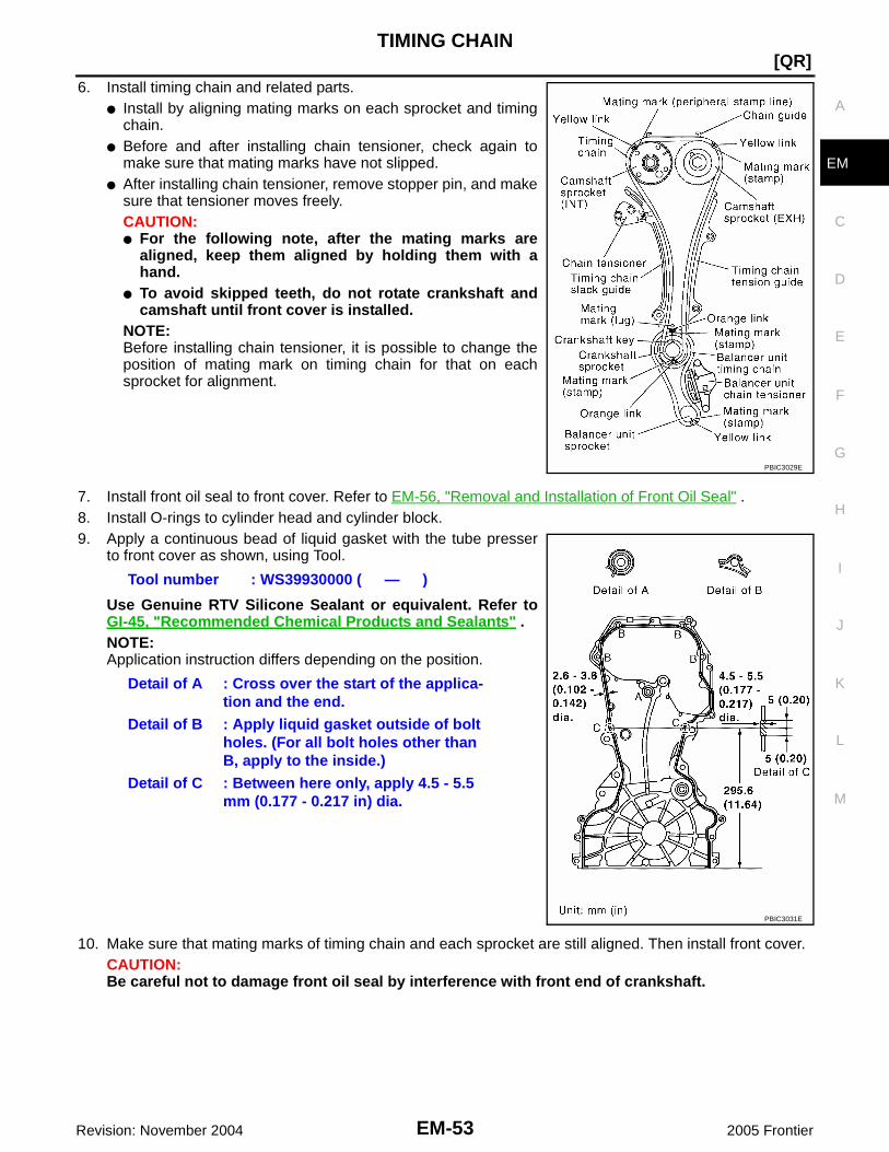
TIMING CHAIN
EM-53
[QR]
C
D
E
F
G
H
I
J
K
L
M
A
EM
Revision: November 2004 2005 Frontier
6. Install timing chain and related parts.● Install by aligning mating marks on each sprocket and timing
chain.● Before and after installing chain tensioner, check again to
make sure that mating marks have not slipped.● After installing chain tensioner, remove stopper pin, and make
sure that tensioner moves freely.CAUTION:● For the following note, after the mating marks are
aligned, keep them aligned by holding them with ahand.
● To avoid skipped teeth, do not rotate crankshaft andcamshaft until front cover is installed.
NOTE:Before installing chain tensioner, it is possible to change theposition of mating mark on timing chain for that on eachsprocket for alignment.
7. Install front oil seal to front cover. Refer to EM-56, "Removal and Installation of Front Oil Seal" .8. Install O-rings to cylinder head and cylinder block.9. Apply a continuous bead of liquid gasket with the tube presser
to front cover as shown, using Tool.
Use Genuine RTV Silicone Sealant or equivalent. Refer toGI-45, "Recommended Chemical Products and Sealants" .NOTE:Application instruction differs depending on the position.
10. Make sure that mating marks of timing chain and each sprocket are still aligned. Then install front cover.CAUTION:Be careful not to damage front oil seal by interference with front end of crankshaft.
PBIC3029E
Tool number : WS39930000 ( — )
Detail of A : Cross over the start of the applica-tion and the end.
Detail of B : Apply liquid gasket outside of boltholes. (For all bolt holes other thanB, apply to the inside.)
Detail of C : Between here only, apply 4.5 - 5.5mm (0.177 - 0.217 in) dia.
PBIC3031E

EM-54Revision: November 2004
[QR]TIMING CHAIN
2005 Frontier
11. Tighten bolts in numerical order as shown.● Refer to the following for locating M6 bolts.
● Tighten bolts to the specified torque.
12. After all bolts are tightened, retighten them to the specifiedtorque in numerical order as shown.CAUTION:Be sure to wipe off any excessive liquid gasket leaking tosurface for fitting oil pan.
13. Install chain guide between camshaft sprockets.14. Install oil rings to the camshaft sprocket (INT) insertion points on backside of intake valve timing control
cover.15. Install O-ring to front cover.16. Apply a continuous bead of liquid gasket using Tool to intake
valve timing control cover as shown.
Use Genuine RTV Silicone Sealant or equivalent. Refer toGI-45, "Recommended Chemical Products and Sealants" .
17. Tighten bolts in numerical order as shown.
18. Install intake valve timing control solenoid valve to intake valve timing control cover if removed.19. Connect ground cables, and install harness clip.20. Insert crankshaft pulley by aligning with crankshaft key.
● When inserting crankshaft pulley with a plastic hammer, tap on its center portion (not circumference).CAUTION:Install protecting front oil seal lip section from any damage.
Bolt position: 45 mm (1.77 in) : 5, 10, 14, 17: 20 mm (0.79 in) : Except the above (Except 1 to 4)
M6 bolts 12.8 N·m (1.3 kg-m, 9 ft-lb)M10 bolts 49.0 N·m (5.0 kg-m, 36 ft-lb)
KBIA0083E
Tool number : WS39930000 ( — )
SBIA0260E
KBIA0085E

TIMING CHAIN
EM-55
[QR]
C
D
E
F
G
H
I
J
K
L
M
A
EM
Revision: November 2004 2005 Frontier
21. Tighten crankshaft pulley bolt using Tool.
● Secure crankshaft pulley using suitable tool, and tighten crankshaft pulley bolt.a. Apply new engine oil to thread and seat surfaces of crankshaft pulley bolt.b. Tighten crankshaft pulley bolt.
c. Put a paint mark on crankshaft pulley, mating with any one of sixeasy to recognize angle marks on bolt flange.
d. Turn another 60° degrees clockwise (angle tightening).● Check the tightening angle with movement of one angle mark.
22. Install all removed parts in the reverse order of removal.
INSPECTION AFTER INSTALLATIONInspection for LeaksThe following are procedures for checking fluid leaks, lubricates leak and exhaust gases leak.● Before starting the engine, check oil fluid levels including engine coolant and engine oil. If less than
required quantity, fill to the specified level. Refer to MA-11, "QR25DE" .● Use procedures below to check for fuel leakage.– Turn ignition switch “ON” (with engine stopped). With fuel pressure applied to fuel piping, check for fuel
leakage at connection points.– Start the engine. With the engine speed increased, check again for fuel leakage at connection points.● Run the engine to check for unusual noise and vibration.
NOTE:If hydraulic pressure inside timing chain tensioner drops after removal/installation, slack in the guide maygenerate a pounding noise during and just after the engine start. However, this is normal. Noise will stopafter hydraulic pressure rises.
● Warm up the engine thoroughly to make sure there is no leakage of fuel, exhaust gases, or any oil/ fluidsincluding engine oil and engine coolant.
● Bleed air from lines and hoses of applicable lines, such as in cooling system.● After cooling down the engine, again check oil/fluid levels including engine oil and engine coolant. Refill to
the specified level, if necessary.
Summary of the inspection items:
* Transmission/transaxle/AT fluid, power steering fluid, brake fluid, etc.
Tool number : KV10112100 (BT-8653-A)
: 42.1 N·m (4.3 kg-m, 31 ft-lb)
SEM751G
Item Before starting engine Engine running After engine stopped
Engine coolant Level Leakage Level
Engine oil Level Leakage Level
Other oils and fluid* Level Leakage Level
Fuel Leakage Leakage Leakage
Exhaust gases — Leakage —

EM-56Revision: November 2004
[QR]OIL SEAL
2005 Frontier
OIL SEAL PFP:12279
Removal and Installation of Valve Oil Seal EBS00NI3
REMOVAL1. Remove fan shroud (lower). Refer to CO-11, "RADIATOR" .2. Rotate crankshaft, and set piston whose valve oil seal is to be removed to TDC. This will prevent valve
from dropping into cylinder.3. Remove camshafts. Refer to EM-35, "CAMSHAFT" .4. Remove valve lifters. Refer to EM-35, "CAMSHAFT" .5. Remove valve collet, valve spring retainer and valve spring
using Tool.
CAUTION:When working, be careful not to damage valve lifter holes.
6. Remove valve spring retainer and valve spring.CAUTION:Do not remove valve spring seat from valve spring.
7. Remove valve oil seal using Tool.
INSTALLATION1. Apply new engine oil to valve oil seal joint surface and seal lip.2. Press in valve oil seal to the height “H” as shown using Tool.
3. Installation of the remaining components is in the reverse order of removal.
Removal and Installation of Front Oil Seal EBS00NI4
REMOVAL1. Remove engine undercover.2. Remove fan shroud (lower); Refer to CO-14, "COOLING FAN"3. Remove cooing fan; Refer to CO-14, "COOLING FAN" .4. Remove drive belt; Refer to EM-13, "DRIVE BELTS" .
Tool numbers : KV10116200 (J-26336-B): KV10115900 (J-26336-20)
WBIA0477E
Tool numbers : KV10107902 (J-38959)
WBIA0478E
Tool numbers : KV10107902 (J-38959)
WBIA0653E

OIL SEAL
EM-57
[QR]
C
D
E
F
G
H
I
J
K
L
M
A
EM
Revision: November 2004 2005 Frontier
5. Remove crankshaft pulley; Refer to EM-47, "TIMING CHAIN" .6. Remove front oil seal using a suitable tool.
CAUTION:Be careful not to damage front cover and crankshaft.
INSTALLATION1. Apply new engine oil to new front oil seal joint surface and seal lip.2. Install front oil seal so that each seal lip is oriented as shown.
● Press-fit front oil seal until it is flush with front end surface offront cover using suitable tool.CAUTION:● Be careful not to damage front cover and crankshaft.● Press-fit oil seal straight to avoid causing burrs or tilt-
ing.
3. Installation of the remaining components is in the reverse order of removal.
Removal and Installation of Rear Oil Seal EBS00NI5
REMOVAL1. Remove transmission assembly. Refer to MT-16, "REMOVAL" (M/T models), MT-65, "REMOVAL" (2WD
models), MT-67, "REMOVAL" (4WD models) or AT-245, "REMOVAL" (2WD), AT-249, "REMOVAL"(4WD) (A/T models).
2. Remove clutch cover and clutch disk (M/T models). Refer to CL-18, "REMOVAL" .3. Remove drive plate (A/T models) or flywheel (M/T models) with power tool. Refer to EM-74, "CYLINDER
BLOCK" .4. Remove rear oil seal with a suitable tool.
CAUTION:Be careful not to damage crankshaft and cylinder block.
INSTALLATION1. Apply new engine oil to new rear oil seal joint surface and seal lip.
SEM829E
SEM715A
PBIC3033E

EM-58Revision: November 2004
[QR]OIL SEAL
2005 Frontier
2. Install rear oil seal so that each seal lip is oriented as shown.
● Press in rear oil seal to the position as shown.
● Press-fit rear oil seal using a suitable drift [outside diameter102 mm (4.02 in), inside diameter 86 mm (3.39 in)].CAUTION:● Be careful not to damage crankshaft and cylinder
block.● Press-fit oil seal straight to avoid causing burrs or tilt-
ing.● Do not touch grease applied onto oil seal lip.
3. Installation of the remaining components is in the reverse order of removal.
SEM715A
WBIA0654E
SBIA0280E

CYLINDER HEAD
EM-59
[QR]
C
D
E
F
G
H
I
J
K
L
M
A
EM
Revision: November 2004 2005 Frontier
CYLINDER HEAD PFP:11041
On-Vehicle Service EBS00NI6
CHECKING COMPRESSION PRESSURE1. Warm up engine thoroughly. Then, stop it.2. Release fuel pressure. Refer to EC-708, "FUEL PRESSURE RELEASE" .3. Disconnect fuel pump fuse to avoid fuel injection during mea-
surement.
4. Remove spark plug from each cylinder. Refer to EM-26, "SPARK PLUG (PLATINUM-TIPPED TYPE)" .5. Connect an engine tachometer (not required in use of CONSULT-II).6. Install a compression tester with an adapter (commercial service
tool) onto spark plug hole.
● Use the adapter whose picking up end inserted to spark plughole is smaller than 20 mm (0.79 in) in diameter. Otherwise, itmay be caught by cylinder head during removal.
7. With accelerator pedal fully depressed, turn ignition switch to “START” for cranking. When the gaugepointer stabilizes, read the compression pressure and the engine rpm. Perform these steps to check eachcylinder.
Compression pressure:Unit: kPa (kg/cm2 , psi) /rpm
CAUTION:Always use fully a changed battery to obtain the specified engine speed.● If the engine speed is out of the specified range, check battery liquid for proper gravity. Check engine
speed again with normal battery gravity.
BBIA0534E
LBIA0448E
SBIA0533E
Standard Minimum Differential limit between cylinders
1,304 (13.3, 189) / 250 1,108 (11.3, 161) / 250 100 (1.0, 14) / 250

EM-60Revision: November 2004
[QR]CYLINDER HEAD
2005 Frontier
● If compression pressure is below minimum value, check valve clearances and parts associated withcombustion chamber (Valve, valve seat, piston, piston ring, cylinder bore, cylinder head, cylinder headgasket). After the checking, measure the compression pressure again.
● If some cylinder has low compression pressure, pour small amount of engine oil into the spark plug holeof the cylinder to re-check it for compression.
● If the added engine oil improves the compression, piston rings may be worn out or damaged. Checkpiston rings and replace if necessary.
● If the compression pressure remains at low level despite the addition of engine oil, valves may be mal-functioning. Check valves for damage. Replace valve or valve seat accordingly.
● If two adjacent cylinders have respectively low compression pressure and their compression remainslow even after the addition of engine oil, cylinder head gasket is leaking. In such a case, replace cylin-der head gasket.
8. After inspection is completed, install removed parts.9. Start the engine, and confirm that the engine runs smoothly.10. Perform trouble diagnosis. If DTC appears, erase it. Refer to EC-710, "TROUBLE DIAGNOSIS" .
Removal and Installation EBS00NI7
REMOVAL1. Release fuel pressure. Refer to EC-708, "FUEL PRESSURE RELEASE" .2. Drain engine coolant. Refer to CO-10, "Changing Engine Coolant" .
CAUTION:● Perform this step when the engine is cold.● Do not spill engine coolant on drive belt.
3. Drain engine oil; Refer to MA-25, "Changing Engine Oil" .CAUTION:● Perform this step when the engine is cold.● Do not spill engine oil on drive belt.
4. Intake manifold and fuel tube assembly; Refer to EM-17, "INTAKE MANIFOLD" .5. Remove fuel injector and fuel tube assembly; Refer to EM-28, "FUEL INJECTOR AND FUEL TUBE" .6. Exhaust manifold and three way catalyst assembly; Refer to EM-20, "EXHAUST MANIFOLD AND
THREE WAY CATALYST" .7. Remove water outlet; Refer to CO-21, "REMOVAL" .8. Remove heater outlet; Refer to CO-21, "WATER OUTLET AND WATER PIPING" .
1. Cylinder head assembly 2. Cylinder head gasket 3. Cylinder head bolt
PBIC3025E

CYLINDER HEAD
EM-61
[QR]
C
D
E
F
G
H
I
J
K
L
M
A
EM
Revision: November 2004 2005 Frontier
NOTE:Can be removed and installed even when assembled with cylinder head.
9. Remove front cover and timing chain. Refer to EM-47, "TIMING CHAIN" .10. Remove camshafts. Refer to EM-35, "CAMSHAFT" .11. Remove cylinder head loosening bolts in reverse order as
shown using power tool.● Using the cylinder head bolt wrench (commercial service tool:
J-24239-01), loosen cylinder head bolts.
12. Remove cylinder head gasket.
INSPECTION AFTER REMOVALCylinder Head Bolts Outer Diameter● Cylinder head bolts are tightened by plastic zone tightening
method. Whenever the size difference between “d1” and “d2”exceeds the limit, replace them with a new one.
● If reduction of outer diameter appears in a position other than“d2”, use it as “d2” point.
Cylinder Head DistortionNOTE:When performing this inspection, cylinder block distortion should be also checking. Refer to EM-94, "CYLIN-DER BLOCK DISTORTION" .1. Wipe off engine oil and remove water scale (like deposit), gasket, sealant, carbon, etc. with a scraper.
CAUTION:Use utmost care not to allow gasket debris to enter passages for engine oil or engine coolant.
2. At each of several locations on bottom surface of cylinder head,measure the distortion in six directions.
● If it exceeds the limit, replace cylinder head.
KBIA0058E
Limit (“d1” – “d2”): 0.23 mm (0.0091 in)
SBIA0269E
Limit : 0.1 mm (0.004 in)
PBIC0075E

EM-62Revision: November 2004
[QR]CYLINDER HEAD
2005 Frontier
INSTALLATION1. Install new cylinder head gasket.2. Install cylinder head follow the steps below to tighten cylinder
head bolts in numerical order as shown.CAUTION:If cylinder head bolts re-used, check their outer diametersbefore installation. Refer to EM-61, "Cylinder Head BoltsOuter Diameter" .NOTE:Apply new engine oil to threads and seating surfaces of mount-ing bolts.
3. Installation of the remaining components is in reverse order of removal.
INSPECTION AFTER INSTALLATIONInspection for LeaksThe following are procedures for checking fluid leaks, lubricates leak and exhaust gases leak.● Before starting the engine, check oil fluid levels including engine coolant and engine oil. If less than
required quantity, fill to the specified level. Refer to MA-11, "QR25DE" .● Use procedures below to check for fuel leakage.– Turn ignition switch “ON” (with engine stopped). With fuel pressure applied to fuel piping, check for fuel
leakage at connection points.– Start the engine. With the engine speed increased, check again for fuel leakage at connection points.● Run the engine to check for unusual noise and vibration.
NOTE:If hydraulic pressure inside timing chain tensioner drops after removal/installation, slack in the guide maygenerate a pounding noise during and just after the engine start. However, this is normal. Noise will stopafter hydraulic pressure rises.
● Warm up the engine thoroughly to make sure there is no leakage of fuel, exhaust gases, or any oil/ fluidsincluding engine oil and engine coolant.
● Bleed air from lines and hoses of applicable lines, such as in cooling system.● After cooling down the engine, again check oil/fluid levels including engine oil and engine coolant. Refill to
the specified level, if necessary.
Tool number : KV10112100 (BT8653-A)KBIA0058E
Step a : 98 N·m (10 kg-m, 72 ft-lb)Step b : Loosen to 0 N·m in the reverse order of
tightening.Step c : 39.2 N·m (4.0 kg-m, 29 ft-lb)Step d : 75° clockwiseStep e : 75° clockwise
WBIA0617E

CYLINDER HEAD
EM-63
[QR]
C
D
E
F
G
H
I
J
K
L
M
A
EM
Revision: November 2004 2005 Frontier
Summary of the inspection items:
* Transmission/transaxle/AT fluid, power steering fluid, brake fluid, etc.
Disassembly and Assembly EBS00NI8
DISASSEMBLY1. Remove spark plug using suitable tool.2. Remove valve lifter.
● Identify installation positions, and store them without mixing them up.
Item Before starting engine Engine running After engine stopped
Engine coolant Level Leakage Level
Engine oil Level Leakage Level
Other oils and fluid* Level Leakage Level
Fuel Leakage Leakage Leakage
Exhaust gases — Leakage —
1. Valve collet 2. Valve spring retainer 3. Valve spring (with valve spring seat)
4. Valve oil seal 5. Valve guide 6. Cylinder head
7. Valve seat 8. Valve (INT) 9. Valve (EXH)
10. Spark plug tube 11. Spark plug
PBIC3024E

EM-64Revision: November 2004
[QR]CYLINDER HEAD
2005 Frontier
3. Remove valve collet, valve spring retainer and valve springusing Tool.
CAUTION:When working, be careful not to damage valve lifter holes.
CAUTION:Do not remove valve spring seat from valve spring.
4. Push valve stem to combustion chamber side, and remove valve.● Identify installation positions, and store them without mixing them up.
5. Remove valve oil seal using Tool.
6. When valve seat must be replaced, refer to EM-68, "VALVE SEAT REPLACEMENT" .7. When valve guide must be replaced, refer to EM-66, "VALVE GUIDE REPLACEMENT" .8. Remove spark plug tube, if necessary.
● Remove it from cylinder head using suitable tool.CAUTION:● Be careful not to damage cylinder head.● Do not remove spark plug tube if not necessary. Once removed, spark plug tube cannot be
reused because of deformation.
ASSEMBLY1. Install valve guide if removed. Refer to EM-66, "VALVE GUIDE REPLACEMENT" .2. Install valve seat if removed. Refer to EM-68, "VALVE SEAT REPLACEMENT" .3. Install valve oil seal using Tool.
NOTE:Install with the valve oil seal to match dimension as shown.
4. Install valve.NOTE:Install larger diameter to intake side.
Tool numbers : KV10116200 (J-26336-B): KV10115900 (J-26336-20)
WBIA0477E
Tool numbers : KV10107902 (J-38959)
WBIA0478E
Tool numbers : KV10107902 (J-38959)
Height “H” : 11.8 - 12.4 mm (0.465 - 0.488 in)
WBIA0653E
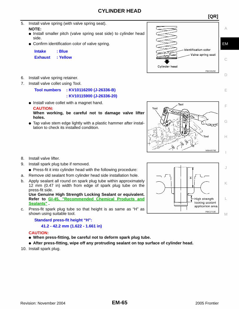
CYLINDER HEAD
EM-65
[QR]
C
D
E
F
G
H
I
J
K
L
M
A
EM
Revision: November 2004 2005 Frontier
5. Install valve spring (with valve spring seat).NOTE:● Install smaller pitch (valve spring seat side) to cylinder head
side.● Confirm identification color of valve spring.
6. Install valve spring retainer.7. Install valve collet using Tool.
● Install valve collet with a magnet hand.CAUTION:When working, be careful not to damage valve lifterholes.
● Tap valve stem edge lightly with a plastic hammer after instal-lation to check its installed condition.
8. Install valve lifter.9. Install spark plug tube if removed.
● Press-fit it into cylinder head with the following procedure:a. Remove old sealant from cylinder head side installation hole.b. Apply sealant all round on spark plug tube within approximately
12 mm (0.47 in) width from edge of spark plug tube on thepress-fit side.Use Genuine High Strength Locking Sealant or equivalent.Refer to GI-45, "Recommended Chemical Products andSealants" .
c. Press-fit spark plug tube so that height is as same as “H” asshown using suitable tool.
CAUTION:● When press-fitting, be careful not to deform spark plug tube.● After press-fitting, wipe off any protruding sealant on top surface of cylinder head.
10. Install spark plug.
Intake : BlueExhaust : Yellow
PBIC0525E
Tool numbers : KV10116200 (J-26336-B): KV10115900 (J-26336-20)
WBIA0578E
Standard press-fit height “H”:41.2 - 42.2 mm (1.622 - 1.661 in)
PBIC2713E

EM-66Revision: November 2004
[QR]CYLINDER HEAD
2005 Frontier
Inspection After Disassembly EBS00NI9
VALVE DIMENSIONS● Check dimensions of each valve. For dimensions, refer to EM-
66, "VALVE DIMENSIONS" .● If dimensions are out of the standard, replace valve.
VALVE GUIDE CLEARANCEValve Stem DiameterMeasure the diameter of valve stem with a micrometer.
Valve Guide Inner DiameterMeasure the inner diameter of valve guide with a bore gauge.
Valve Guide Clearance(Valve guide clearance) = (Valve guide inner diameter) – (Valve stem diameter).
● If it exceeds the limit, replace valve guide and/or valve. When valve guide must be replaced, refer to EM-66, "VALVE GUIDE REPLACEMENT" .
VALVE GUIDE REPLACEMENTWhen valve guide is removed, replace with oversized [0.2 mm (0.008 in)] valve guide.
SEM188A
StandardIntake : 5.965 - 5.980 mm (0.2348 - 0.2354 in)Exhaust : 5.955 - 5.970 mm (0.2344 - 0.2350 in)
SEM938C
StandardIntake and Exhaust
: 6.000 - 6.018 mm (0.2362 - 0.2369 in)
Valve guide clearance:Standard
Intake : 0.020 - 0.053 mm (0.0008 - 0.0021 in)Exhaust : 0.030 - 0.063 mm (0.0012 - 0.0025 in)
LimitIntake : 0.08 mm (0.003 in)Exhaust : 0.09 mm (0.004 in)

CYLINDER HEAD
EM-67
[QR]
C
D
E
F
G
H
I
J
K
L
M
A
EM
Revision: November 2004 2005 Frontier
1. To remove valve guide, heat cylinder head to 110° to 130°C(230° to 266°F) by soaking in heated oil.
2. Drive out valve guide with a press [under a 20 kN (2 ton, 2.2 USton, 2.0 lmp ton) force] or suitable tool.CAUTION:Cylinder head contains heat, when working, wear protectiveequipment to avoid getting burned.
3. Ream cylinder head valve guide hole using suitable reamer.
4. Heat cylinder head to 110° to 130°C (230° to 266°F) by soakingin heated oil.
5. Press valve guide from camshaft side to dimensions as shownusing suitable tool.
CAUTION:Cylinder head contains heat, when working, wear protectiveequipment to avoid getting burned.
SEM008A
SEM931C
Valve guide hole diameter (for service parts):Intake and exhaust
: 10.175 - 10.196 mm (0.4006 - 0.4014 in)
SEM932C
SEM008A
Projection “H”:Intake : 10.1 - 10.3 mm (0.398 - 0.406 in)Exhaust : 10.0 - 10.4 mm (0.394 - 0.409 in)
PBIC2187E

EM-68Revision: November 2004
[QR]CYLINDER HEAD
2005 Frontier
6. Apply reamer finish to valve guide using suitable reamer.
VALVE SEAT CONTACT● After confirming that the dimensions of valve guides and valves
are within specifications, perform this procedure.● Apply prussian blue (or white lead) onto contacting surface of
valve seat to check the condition of the valve contact on the sur-face.
● Check if the contact area band is continuous all around the cir-cumference.
● If not, grind to adjust valve fitting and check again. If the contact-ing surface still has NG conditions even after the re-check,replace valve seat. Refer to EM-68, "VALVE SEAT REPLACE-MENT" .
VALVE SEAT REPLACEMENTWhen valve seat is removed, replace with oversized [0.5 mm (0.020 in)] valve seat.1. Bore out old seat until it collapses. Boring should not continue beyond the bottom face of the seat recess
in cylinder head. Set the machine depth stop to ensure this. Refer to EM-105, "Valve Seat" .CAUTION:Prevent to scratch cylinder head by excessive boring.
2. Ream cylinder head recess diameter for service valve seat.
● Be sure to ream in circles concentric to the valve guide center.This will enable valve seat to fit correctly.
3. Heat cylinder head to 110° to 130°C (230° to 266°F) by soakingin heated oil.
4. Provide valve seats cooled well with a dry ice. Press-fit valve seats into cylinder head.CAUTION:● Avoid directly to touching cold valve seats.
StandardIntake and exhaust:
6.000 - 6.018 mm (0.2362 - 0.2369 in)
SEM932C
SBIA0322E
Oversize [0.5 mm (0.020 in)]Intake : 37.000 - 37.016 mm (1.4567 - 1.4573 in)Exhaust : 32.000 - 32.016 mm (1.2598 - 1.2605 in)
SEM795A
SEM008A
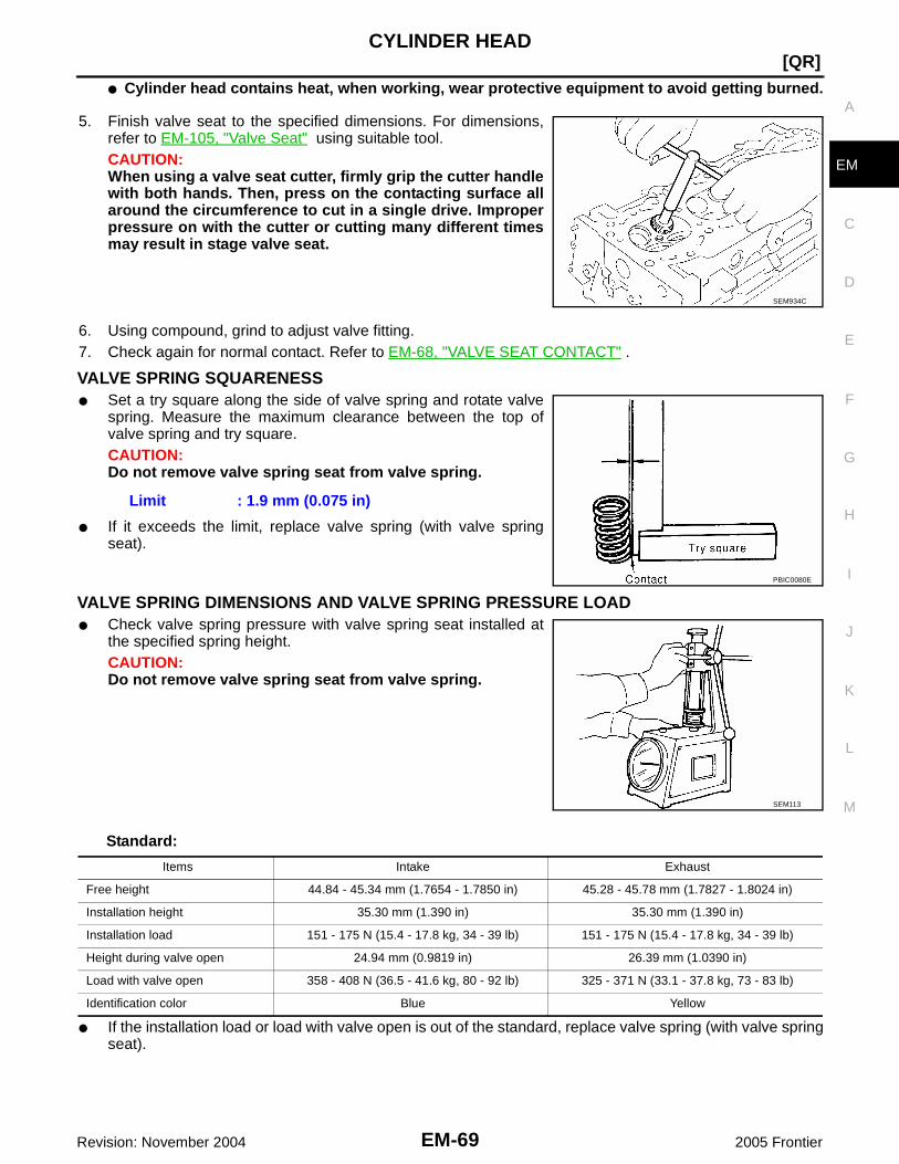
CYLINDER HEAD
EM-69
[QR]
C
D
E
F
G
H
I
J
K
L
M
A
EM
Revision: November 2004 2005 Frontier
● Cylinder head contains heat, when working, wear protective equipment to avoid getting burned.
5. Finish valve seat to the specified dimensions. For dimensions,refer to EM-105, "Valve Seat" using suitable tool.CAUTION:When using a valve seat cutter, firmly grip the cutter handlewith both hands. Then, press on the contacting surface allaround the circumference to cut in a single drive. Improperpressure on with the cutter or cutting many different timesmay result in stage valve seat.
6. Using compound, grind to adjust valve fitting.7. Check again for normal contact. Refer to EM-68, "VALVE SEAT CONTACT" .
VALVE SPRING SQUARENESS● Set a try square along the side of valve spring and rotate valve
spring. Measure the maximum clearance between the top ofvalve spring and try square.CAUTION:Do not remove valve spring seat from valve spring.
● If it exceeds the limit, replace valve spring (with valve springseat).
VALVE SPRING DIMENSIONS AND VALVE SPRING PRESSURE LOAD● Check valve spring pressure with valve spring seat installed at
the specified spring height.CAUTION:Do not remove valve spring seat from valve spring.
Standard:
● If the installation load or load with valve open is out of the standard, replace valve spring (with valve springseat).
SEM934C
Limit : 1.9 mm (0.075 in)
PBIC0080E
SEM113
Items Intake Exhaust
Free height 44.84 - 45.34 mm (1.7654 - 1.7850 in) 45.28 - 45.78 mm (1.7827 - 1.8024 in)
Installation height 35.30 mm (1.390 in) 35.30 mm (1.390 in)
Installation load 151 - 175 N (15.4 - 17.8 kg, 34 - 39 lb) 151 - 175 N (15.4 - 17.8 kg, 34 - 39 lb)
Height during valve open 24.94 mm (0.9819 in) 26.39 mm (1.0390 in)
Load with valve open 358 - 408 N (36.5 - 41.6 kg, 80 - 92 lb) 325 - 371 N (33.1 - 37.8 kg, 73 - 83 lb)
Identification color Blue Yellow

EM-70Revision: November 2004
[QR]ENGINE ASSEMBLY
2005 Frontier
ENGINE ASSEMBLY PFP:10001
Removal and Installation EBS00NIA
WARNING:● Situate the vehicle on a flat and solid surface.● Place chocks at front and back of rear wheels.● Attach proper slingers and bolts described in PARTS CATALOG if engine slingers are not
equipped.CAUTION:● Always be careful to work safely, avoid forceful or uninstructed operations.● Do not start working until exhaust system and coolant are cool enough.● If items or work required are not covered by the engine section, refer to the applicable sections.● Always use the support point specified for lifting.● Use either 2-pole lift type or separate type lift as best you can. If board-on type is used for
unavoidable reasons, support at the rear axle jacking point with a transmission jack or similar toolbefore starting work, in preparation for the backward shift of center of gravity.
● For supporting points for lifting and jacking point at rear axle, refer to GI-40, "Garage Jack andSafety Stand" .
1. RH engine mounting bracket (upper) 2. RH engine mounting insulator 3. RH engine mounting bracket (lower)
4. LH engine mounting bracket (upper) 5. LH engine mounting insulator 6. LH engine mounting bracket (lower)
7. Rear engine mounting insulator
LBIA0443E

ENGINE ASSEMBLY
EM-71
[QR]
C
D
E
F
G
H
I
J
K
L
M
A
EM
Revision: November 2004 2005 Frontier
REMOVAL1. Drain engine coolant. Refer to MA-14, "DRAINING ENGINE COOLANT" .2. Partially drain A/T fluid. Refer to MA-32, "Changing the Automatic Transmission Fluid (ATF)" .3. Release fuel pressure. Refer to EC-95, "FUEL PRESSURE RELEASE" .4. Remove the engine hood. Refer to BL-13, "Removal and Installation of Hood Assembly" .5. Remove the air duct and air cleaner case assembly. Refer to EM-15, "REMOVAL" .6. Disconnect vacuum hose between vehicle and engine and set it aside.7. Remove the radiator assembly and hoses. Refer to CO-11, "REMOVAL" .8. Remove the drive belts. Refer to EM-13, "REMOVAL" .9. Remove the engine cooling fan. Refer to CO-14, "REMOVAL" .10. Disconnect the engine room harness from the engine side and set it aside for easier work.11. Disconnect the engine harness grounds.12. Disconnect the reservoir tank for power steering from engine and move it aside for easier work.13. Disconnect power steering oil pump from engine and position out of the way for easier work. Refer to PS-
21, "REMOVAL" .14. Remove the A/C compressor bolts and set aside. Refer to MTC-101, "REMOVAL" .15. Disconnect brake booster vacuum line.16. Disconnect EVAP line.17. Disconnect the fuel hose at the engine side connection. Refer to EM-28, "REMOVAL" .18. Disconnect the heater hoses at cowl, and install plugs to avoid leakage of engine coolant.19. Remove the A/T oil level indicator and indicator tube.20. Remove three way catalyst. Refer to EM-20, "REMOVAL" .21. Install engine slingers into left bank and right bank.
22. Remove transmission. Refer to MT-16, "REMOVAL"(FS5R30A), MT-65, "REMOVAL" (FS6R31A) (2WD models),MT-67, "REMOVAL" (4WD models).
23. Lift with hoist and secure the engine in position.24. Remove engine assembly from vehicle, avoiding interference
with vehicle body.CAUTION:● Before and during this lifting, always check if any harnesses are left connected.
25. Remove the parts that may restrict installation of engine to engine stand.NOTE:The procedure is described assuming that you use a engine holding the surface, to which transmission isinstalled.
a. Remove drive plate.● Holding crankshaft pulley bolts, lock crankshaft to remove drive plate bolts.● Loosen bolts diagonally.
Engine slinger torqueFront engine slinger : 48.1 N·m (4.9 kg-m, 35 ft-lb)Rear engine slinger : 22.0 N·m (2.2 kg-m, 16 ft-lb)
LBIA0449E

EM-72Revision: November 2004
[QR]ENGINE ASSEMBLY
2005 Frontier
CAUTION:● Be careful not to damage drive plate. Especially avoid
deforming and damaging of signal plate teeth (circum-ference position).
● Place the drive plate with signal plate surface facingother than downward.
● Keep magnetic materials away from signal plate.
CAUTION:Use an engine stand that has a load capacity [approximately 240kg (529 lb) or more] large enoughfor supporting the engine weight.● If the load capacity of the stand is not adequate, remove the following parts beforehand to
reduce the potential risk of overturning the stand.– Remove fuel tube and fuel injector assembly. Refer to EM-28, "REMOVAL" .– Remove intake manifold. Refer to EM-17, "REMOVAL" .– Remove rocker cover. Refer to EM-33, "REMOVAL" .– Other removable brackets.CAUTION:Before removing the hanging chains, make sure the engine stand is stable and there is no risk ofoverturning.
26. Remove alternator. Refer to SC-37, "REMOVAL" .27. Remove engine mounting insulator bracket (upper) with power tool.
INSTALLATIONNote the following, and installation is in the reverse order of removal.● Do not allow engine oil to get on engine mounting insulator. Be careful not to damage engine mounting
insulator.● When installation directions are specified, install parts according to the direction marks on them referring
to the figure of components.● Make sure that each mounting insulator is seated properly, and tighten nuts and bolts.
INSPECTION AFTER INSTALLATIONInspection for LeaksThe following are procedures for checking fluid leaks, lubricates leak and exhaust gases leak.● Before starting the engine, check oil fluid levels including engine coolant and engine oil. If less than
required quantity, fill to the specified level. Refer to MA-11, "QR25DE" .● Use procedures below to check for fuel leakage.● Turn ignition switch “ON” (with engine stopped). With fuel pressure applied to fuel piping, check for fuel
leakage at connection points.● Start the engine. With the engine speed increased, check again for fuel leakage at connection points.● Run the engine to check for unusual noise and vibration.
NOTE:If hydraulic pressure inside timing chain tensioner drops after removal/installation, slack in the guide maygenerate a pounding noise during and just after the engine start. However, this is normal. Noise will stopafter hydraulic pressure rises.
● Warm up the engine thoroughly to make sure there is no leakage of fuel, exhaust gases, or any oil/ fluidsincluding engine oil and engine coolant.
● Bleed air from lines and hoses of applicable lines, such as in cooling system.● After cooling down the engine, again check oil/fluid levels including engine oil and engine coolant. Refill to
the specified level, if necessary.
KBIA2491E

ENGINE ASSEMBLY
EM-73
[QR]
C
D
E
F
G
H
I
J
K
L
M
A
EM
Revision: November 2004 2005 Frontier
Summary of the inspection items:
* Transmission/transaxle/AT fluid, power steering fluid, brake fluid, etc.
Item Before starting engine Engine running After engine stopped
Engine coolant Level Leakage Level
Engine oil Level Leakage Level
Other oils and fluid* Level Leakage Level
Fuel Leakage Leakage Leakage
Exhaust gases — Leakage —

EM-74Revision: November 2004
[QR]CYLINDER BLOCK
2005 Frontier
CYLINDER BLOCK PFP:11010
Disassembly and Assembly EBS00NIC
PBIC3022E

CYLINDER BLOCK
EM-75
[QR]
C
D
E
F
G
H
I
J
K
L
M
A
EM
Revision: November 2004 2005 Frontier
DISASSEMBLYNOTE:Explained here is how to disassemble with an engine stand supporting mating surface of transmission. Whenusing different type of engine stand, note with difference in steps and etc.1. Remove the engine and the transmission assembly from the vehicle, and separate the transmission
assembly from the engine. Refer to EM-70, "ENGINE ASSEMBLY" .2. Remove clutch cover and clutch disc (M/T models). Refer to CL-18, "CLUTCH DISC, CLUTCH COVER" .
1. Cylinder block 2. O-ring 3. Crankshaft position sensor (POS)
4. Knock sensor 5. Oil pressure switch 6. Water drain plug
7. Oil level gauge 8. Oil level gauge guide 9. O–ring
10. Lower cylinder block 11. Lower cylinder block mounting bolt 12. Snap ring
13. Connecting rod 14. Connecting rod bearing 15. Connecting rod bearing cap
16. Connecting rod bolt 17. Piston 18. Oil ring
19. Second ring 20. Top ring 21. Piston pin
22. Thrust bearing 23. Main bearing upper 24. Crankshaft
25. Crankshaft key 26. Main bearing lower 27. Rear oil seal
28. Pilot convertor (A/T models) 29. Pilot bushing (M/T models) 30. Signal plate
31. Drive plate (A/T models) 32. Reinforce plate (A/T models) 33. Flywheel (M/T models)
1. Cylinder block 2. Gasket 3. Cylinder block heater
4. Connector protector cap
PBIC3021E

EM-76Revision: November 2004
[QR]CYLINDER BLOCK
2005 Frontier
3. Remove flywheel (M/T models) or drive plate (A/T models) withpower tool.● Secure crankshaft with a stopper plate, and remove bolts.● Loosen bolts using suitable tool.
CAUTION:Be careful not to damage or scratch drive plate (A/T mod-els) and contact surface for clutch disc of flywheel (M/T models).NOTE:The flywheel, two block construction, allows movement in response to transmission side pressure, orwhen twisted in its rotational direction. Therefore, some amount of noise is normal.
4. Lift the engine with a hoist to install it onto widely use enginestand.CAUTION:● Use the engine stand that has a load capacity [approxi-
mately 240kg (529 lb) or more] large enough for support-ing the engine weight.
● Before removing the hanging chains, make sure theengine stand is stable and there is no risk of overturning.
NOTE:The figure shows an example of widely use engine stand thatcan support mating surface of transmission with flywheel (M/Tmodels) or drive plate (A/T models) removed.
5. Drain engine oil. Refer to LU-8, "Changing Engine Oil" .6. Drain engine coolant by removing water drain plug from inside of
the engine.
7. Remove cylinder head with power tool. Refer to EM-59, "CYLINDER HEAD" .8. Remove knock sensor.
CAUTION:Carefully handle knock sensor avoiding shocks.
9. Remove crankshaft position sensor (POS).CAUTION:● Avoid impacts such as a dropping.● Do not disassemble.● Keep it away from metal particles.● Do not place the sensor in a location where it is exposed
to magnetism.
Flywheel (M/T models): size T55 (commercial service tool)
Drive plate (A/T models): size E20
PBIC2352E
PBIC0085E
PBIC2716E
PBIC2191E

CYLINDER BLOCK
EM-77
[QR]
C
D
E
F
G
H
I
J
K
L
M
A
EM
Revision: November 2004 2005 Frontier
10. Remove oil pressure sensor using a suitable tool.CAUTION:Do not drop or shock oil pressure sensor.
11. Remove pilot converter (A/T models) or pilot bushing (M/T mod-els) using Tool.
12. Remove piston and connecting rod assembly with the following procedure:● Before removing piston and connecting rod assembly, check the connecting rod side clearance. Refer
to EM-91, "CONNECTING ROD SIDE CLEARANCE" .13. Position crankshaft pin corresponding to connecting rod to be removed onto the bottom dead center.14. Remove connecting rod cap.15. Push piston and connecting rod assembly out to the cylinder
head side using suitable tool.CAUTION:Be careful not to damage the cylinder wall and crankshaftpin, resulting from an interference of the connecting rod bigend.
16. Remove connecting rod bearings.CAUTION:Identify installation positions, and store them without mixing them up.
17. Remove piston rings form piston; using piston ring expander or suitable tool.● Before removing piston rings, check the piston ring side clear-
ance. Refer to EM-92, "PISTON RING SIDE CLEARANCE" .CAUTION:● When removing piston rings, be careful not to damage
the piston.● Be careful not to damage piston rings by expanding
them excessively.
Tool number : ST16610001 (J-23907)
WBIA0618E
PBIC0259E
PBIC0087E

EM-78Revision: November 2004
[QR]CYLINDER BLOCK
2005 Frontier
18. Remove piston from connecting rod with the following procedure:a. Remove snap rings; using suitable snap ring pliers.
b. Heat piston to 60° to 70°C (140° to 158°F) with an industrial usedrier or equivalent.
c. Push out piston pin with a stick of outer diameter approximately19 mm (0.75 in).
19. Remove lower cylinder block bolts.● Before loosening lower cylinder block bolts, measure crankshaft end play. Refer to EM-91, "CRANK-
SHAFT END PLAY" .● Loosen them in reverse order as shown, and remove them.NOTE:Use TORX socket (size E14) for bolts No. 1 to 10.
20. Remove lower cylinder block.● Cut liquid gasket for removal; using Tool
CAUTION:Be careful not to damage the mounting surface.
PBIC1638E
PBIC1639E
PBIC0262E
PBIC2718E
Tool number : KV10111100 (J-37228)

CYLINDER BLOCK
EM-79
[QR]
C
D
E
F
G
H
I
J
K
L
M
A
EM
Revision: November 2004 2005 Frontier
21. Remove crankshaft.CAUTION:● Be careful not damage or deform signal plate mounted on
crankshaft.● When setting crankshaft on a flat floor surface, use a
block of wood to avoid interference between signal plateand the floor surface.
● Do not remove signal plate unless it is necessary to doso.
NOTE:When removing or installing signal plate, use TORX socket (sizeT30).
22. Pull rear oil seal out from rear end of crankshaft.NOTE:When replacing rear oil seal without removing lower cylinder block, use a suitable tool to remove the oilseal installed between crankshaft and cylinder block out.CAUTION:Be careful not to damage crankshaft and cylinder block.
23. Remove main bearings and thrust bearings from cylinder block and lower cylinder block.CAUTION:Identify installation positions, and store them without mixing them up.
ASSEMBLY1. Using compressed air, clean out the coolant and oil passages in the cylinder block, the cylinder bore and
the crankcase to remove any foreign material.CAUTION:Use approved safety glasses to protect your eyes.
2. Apply Silicone RTV Sealant to the drain plugs. Install the drainplugs on the cylinder block.● Use Genuine Silicone RTV Sealant, or equivalent. Refer to
GI-45, "Recommended Chemical Products and Sealants" .● Replace the copper washers with new ones.
3. Install the main bearings and the thrust bearings.a. Remove dust, dirt, and oil from the bearing mating surfaces of
the cylinder block and lower cylinder block.b. Install the thrust bearings to both sides of the No. 3 main bearing
journal on the cylinder block.● Install the thrust bearings with the oil groove facing the crank-
shaft arm (outside).
SBIA0275E
WBIA0159E
PBIC0264E

EM-80Revision: November 2004
[QR]CYLINDER BLOCK
2005 Frontier
c. Install the main bearings paying attention to their position anddirection.● The main bearing with an oil hole and groove goes on the cyl-
inder block. The one without them goes on the lower cylinderblock.
● Only the main bearing (on the cylinder block) for No. 3 journalhas different specifications.
● Before installing the bearings, apply engine oil to the bearingfriction surface (inside). Do not apply oil to the back surface,but thoroughly clean it.
● When installing, align the bearing stopper to the notch.● Make sure that the oil holes on the cylinder block and those on the corresponding bearing are aligned.
4. Install the signal plate to the crankshaft.a. Position the crankshaft and signal plate using a positioning
dowel pin, and tighten the signal plate bolts to specification.
b. Remove the dowel pin.CAUTION:Be sure to remove dowel pin before installing the crank-shaft.NOTE:Dowel pins for the crankshaft and signal plate are supplied as aset for each.
5. Install the crankshaft onto the cylinder block.● While turning the crankshaft by hand, check that it turns smoothly.CAUTION:Do not install rear oil seal at this time.
6. Apply Silicone RTV Sealant to positions shown and install thelower cylinder block.● Use Genuine Silicone RTV Sealant, or equivalent. Refer to
GI-45, "Recommended Chemical Products and Sealants" .NOTE:Cylinder block and lower cylinder block are machined together.Neither of them can be replaced separately.CAUTION:After the Silicone RTV Sealant is applied, the lower cylinderblock installation must be finished within 5 minutes.
7. Tighten lower cylinder block bolts in three steps in the order asshown; Using Tool.CAUTION:There are more processes to complete the tightening oflower cylinder bolts. However stop procedure after step 1and install rear oil seal.
SBIA0277E
Signal plate bolts : 18.5 N·m (1.9 kg-m, 14 ft-lb)
SBIA0278E
WBIA0160E
Lower cylinder block boltsStep 1 (bolts 11 - 22) : 25.1 N·m (2.6 kg-m, 19 ft-lb)Step 2 (bolts 1 - 10) : 39.2 N·m (4.0 kg-m, 29 ft-lb)Step 3 (bolts 1 - 10) : 60° - 65° (target: 60°) KBIA0063E

CYLINDER BLOCK
EM-81
[QR]
C
D
E
F
G
H
I
J
K
L
M
A
EM
Revision: November 2004 2005 Frontier
Install rear oil seal using a suitable drift.CAUTION:● Do not touch grease applied onto oil seal lip.● Be careful not to damage crankshaft and/or cylinder
block.● Press fit oil seal straight to avoid causing burrs or tilting.
NOTE:● Apply new engine oil to threads and seat surfaces of the bolts.CAUTION:Check tightening angle using Tool. Do not tighten by visualinspection.
● Wipe off completely any protruding Silicone RTV Sealant onthe exterior of engine.
● Check crankshaft side clearance. Refer to EM-109, "CRANK-SHAFT" .
● After installing the bolts, make sure that the crankshaft can berotated smoothly by hand.
8. Apply new engine oil to new oil seal and install it using a suitabletool.● Install new oil seal in the direction shown.
9. Install the piston to the connecting rod. Assemble the components in their original positions.a. Using a snap ring pliers, install the snap ring into the grooves of the piston's rear side.
● Insert the piston pin snap ring fully into groove.b. Install the piston to the connecting rod.
● Using a heat gun, heat the piston [approximately 60° - 70° C (140° - 158° F)] until the piston pin can bepushed in by hand without excessive force. From the front to the rear, insert the piston pin into the pis-ton and the connecting rod.
SBIA0280E
SBIA0281E
Tool number : KV10112100 (BT-8653-A)
WBIA0619E
SEM715A

EM-82Revision: November 2004
[QR]CYLINDER BLOCK
2005 Frontier
● Assemble so that the front mark on the piston crown and theoil holes and the cylinder No. on the connecting rod are posi-tioned as shown in the figure.
c. Install the piston pin snap ring into the front of the piston.● Check that the connecting rod moves smoothly.
10. Using a piston ring expander, install the piston rings. Assemblethe components in their original positions.CAUTION:Be careful not to damage the piston.● Position each ring with the gap as shown in the figure, refer-
encing the piston front mark as the starting point.● Install the top ring and the second ring with the stamped sur-
face facing upward.
11. Install the connecting rod bearings to the connecting rod and theconnecting rod cap. Assemble the components in their originalpositions.● When installing the connecting rod bearings, apply engine oil
to the bearing friction surface (inside). Do not apply oil to theback surface, but thoroughly clean the back.
● When installing, align the connecting rod bearing stopper pro-trusion with the notch of the connecting rod to install.
● Check the oil holes on the connecting rod and those on thecorresponding bearing are aligned.
12. Install the piston and connecting rod assembly to the crankshaft.Assemble the components in their original positions.● Rotate the crankshaft so the pin corresponding to the con-
necting rod to be installed is at the bottom dead center posi-tion.
● Apply engine oil sufficiently to the cylinder bore, piston, andcrankshaft pin.
● Match the cylinder position number with the cylinder No. onthe connecting rod for installation.
● Install the piston with the front mark on the piston crown fac-ing the front of the engine using Tool.
CAUTION:Be careful not to damage the crankshaft pin, resulting from an interference of the connecting rodbig end.
PBIC0099E
Stamped mark : 2ND (second ring)PBIC0100E
PBIC0266E
WBIA0620E

CYLINDER BLOCK
EM-83
[QR]
C
D
E
F
G
H
I
J
K
L
M
A
EM
Revision: November 2004 2005 Frontier
13. Install the connecting rod caps. Assemble the components intheir original positions.● Match the stamped cylinder number marks on the connecting
rod with those on the cap to install.
14. Tighten the connecting rod bolts using Tool in four steps as fol-lows:● Apply engine oil to the threads and seats of the connecting
rod bolts.CAUTION:Always use either an angle wrench or protractor. Avoidtightening based on visual check alone.
● Check the connecting rod side clearance. Refer toEM-91, "CONNECTING ROD SIDE CLEARANCE" .● After tightening the bolts, make sure that the crankshaft rotates smoothly.
15. Install flywheel (M/T Models), or drive plate (A/T Models).● Install drive plate, reinforcement plate and pilot converter as
shown.● Using a drift with 33 mm (1.30 in) diameter, push pilot con-
verter into the end of the crankshaft.● Press fit pilot bushing into the crankshaft as shown; using a
suitable drift of 19 mm (0.75 in)
16. Install the cylinder block heater.
17. Install the knock sensor.● Make sure that there is no foreign material on the cylinder
block mating surface and the back surface of the knock sen-sor.
● Install the knock sensor with the connector facing lower left by45° as shown.
● Do not tighten the knock sensor bolt while holding the con-nector.
● Make sure that the knock sensor does not interfere with othercomponents.
CAUTION:If the knock sensor is dropped, replace it with new one.
18. Install the crankshaft position sensor (POS).
SBIA0282E
Step 1 : 27.4 N·m (2.8 kg-m, 20 lb-ft)Step 2 : 0 N·m (0 kg-m, 0 lb-ftStep 3 : 19.6 N·m (2.0 kg-m, 14 ft-lb)Step 4 : 85° - 95° (target 90° degrees)
WBIA0621E
KBIA0075E
Cylinder block heater : 73.5 N·m (7.5 kg-m, 54 ft-lb)
Knock sensor bolt : 21.1 N·m (2.2 kg-m, 16 ft-lb)PBIC3020E

EM-84Revision: November 2004
[QR]CYLINDER BLOCK
2005 Frontier
19. Installation of remaining components is in reverse order of removal.
How to Select Piston and Bearing EBS00NID
DESCRIPTION
*For the service parts, the grade for fitting cannot be selected between piston pin and connecting rod. (Only grade “0” is available.) Theinformation at the shipment from the plant is described as a reference.
● The identification grade stamped on each part is the grade for the dimension measured in new condition.This grade cannot apply to reused parts.
● For reused or repaired parts, measure the dimension accurately. Determine the grade by comparing themeasurement with the values of each selection table.
● For details of the measurement method of each part, the reuse standards and the selection method of theselective fitting parts, refer to the text.
HOW TO SELECT PISTONWhen New Cylinder Block Is Used● Check the cylinder bore grade on rear-left side of cylinder block,
and select piston of the same grade.● If there is a corrected stamp mark on cylinder block, use it as a
correct reference.
Crankshaft positionsensor bolt
: 7.0 N·m (0.71 kg-m, 62 in-lb)
Selection points Selection parts Selection items Selection methods
Between cylinder block andcrankshaft
Main bearingMain bearing grade (bearingthickness)
Determined by match of cylin-der block bearing housinggrade (inner diameter of hous-ing) and crankshaft journalgrade (outer diameter of jour-nal)
Between crankshaft and con-necting rod
Connecting rod bearingConnecting rod bearing grade(bearing thickness)
Combining service grades forconnecting rod big end diame-ter and crankshaft pin outerdiameter determine connectingrod bearing selection.
Between cylinder block and pis-ton
Piston and piston pin assembly(piston is available togetherwith piston pin as an assembly.)
Piston grade (piston skirt diam-eter)
Piston grade = cylinder boregrade (inner diameter of bore)
Between piston and connecting
rod* — — —
SBIA0283E
PBIC3019E

CYLINDER BLOCK
EM-85
[QR]
C
D
E
F
G
H
I
J
K
L
M
A
EM
Revision: November 2004 2005 Frontier
When Cylinder Block Is Reused1. Measure the cylinder bore inner diameter. Refer to EM-95, "Cylinder Bore Inner Diameter" .2. Determine the bore grade by comparing the measurement with the values under the cylinder bore inner
diameter of the “Piston Selection Table”.3. Select piston of the same grade.
Piston Selection TableUnit: mm (in)
NOTE:● There is no piston grade “1”.● Piston is available together with piston pin as an assembly.● The piston pin (piston pin hole) grade is provided only for the parts installed at the plant. For service parts,
no grades can be selected. (Only grade “0” is available.)
HOW TO SELECT CONNECTING ROD BEARINGWhen New Connecting Rod and Crankshaft Are Used1. Apply connecting rod big end diameter grade stamped on con-
necting rod side face to the row in the “Connecting Rod BearingSelection Table”.
2. Apply crankshaft pin journal diameter grade stamped on crank-shaft front side to the column in the “Connecting Rod BearingSelection Table”.
3. Read the symbol at the cross point of selected row and column in the “Connecting Rod Bearing SelectionTable”.
4. Apply the symbol obtained to the “Connecting Rod Bearing Grade Table” to select connecting rod bearing.
When Crankshaft and Connecting Rod Are Reused1. Measure the dimensions of the connecting rod big end diameter and crankshaft pin journal diameter indi-
vidually. Refer to EM-93, "CONNECTING ROD BIG END DIAMETER" and EM-97, "CRANKSHAFT PINJOURNAL DIAMETER" .
2. Apply the measured dimension to the “Connecting Rod Bearing Selection Table”.3. Read the symbol at the cross point of selected row and column in the “Connecting Rod Bearing Selection
Table”.4. Apply the symbol obtained to the “Connecting Rod Bearing Grade Table” to select connecting rod bearing.
Grade number (Mark) 2 (or no mark) 3
Cylinder bore Inner diameter 89.010 - 89.020 (3.5043 - 3.5047) 89.020 - 89.030 (3.5047 - 3.5051)
Piston skirt diameter 88.990 - 89.000 (3.5035 - 3.5039) 89.000 - 89.010 (3.5039 - 3.5043)
PBIC2196E
PBIC2198E

EM-86Revision: November 2004
[QR]CYLINDER BLOCK
2005 Frontier
Connecting Rod Bearing Selection Table
Connecting Rod Bearing Grade TableUnit: mm (in)
Undersize Bearings Usage Guide● When the specified connecting rod bearing oil clearance is not obtained with standard size connecting rod
bearings, use undersize (US) bearings.● When using undersize (US) bearing, measure the connecting rod bearing inner diameter with bearing
installed, and grind the crankshaft pin so that the connecting rod bearing oil clearance satisfies the stan-dard.
PBIC2199E
Grade number 0 1 2 3
Thickness1.495 - 1.499
(0.0589 - 0.0590)1.499 - 1.503
(0.0590 - 0.0592)1.503 - 1.507
(0.0592 - 0.0593)1.507 - 1.511
(0.0593 - 0.0595)
Identification color Black Brown Green Yellow

CYLINDER BLOCK
EM-87
[QR]
C
D
E
F
G
H
I
J
K
L
M
A
EM
Revision: November 2004 2005 Frontier
CAUTION:In grinding crankshaft pin to use undersize bearings, keep thefillet R [1.5 - 1.7 mm (0.059 - 0.067 in)].
Bearing undersize tableUnit: mm (in)
HOW TO SELECT MAIN BEARINGWhen New Cylinder Block and Crankshaft Are Used1. “Main Bearing Selection Table” rows correspond to main bearing
housing grade on rear-left side of cylinder block.● If there is a corrected stamp mark on cylinder block, use it as
a correct reference.
2. Apply main journal diameter grade stamped on crankshaft frontside to column in the “Main Bearing Selection Table”.
3. Read the symbol at the cross point of selected row and column in the “Main Bearing Selection Table”.CAUTION:There are two main bearing selection tables. One is for odd-numbered journals (No. 1, 3 and 5) andthe other is for even-numbered journals (No. 2 and 4). Make certain to use the appropriate table.This is due to differences in the specified clearances.
4. Apply the symbol obtained to the “Main Bearing Grade Table” to select main bearing.NOTE:Service part is available as a set of both upper and lower.
When Cylinder Block and Crankshaft Are Reused1. Measure the dimensions of the cylinder block main bearing housing inner diameter and crankshaft main
journal diameter individually. Refer to EM-95, "MAIN BEARING HOUSING INNER DIAMETER" and EM-96, "CRANKSHAFT MAIN JOURNAL DIAMETER" .
2. Apply the measured dimension to the “Main Bearing Selection Table”.
PBIC2200E
Size Thickness
US 0.25 (0.0098) 1.624 - 1.632 (0.0639 - 0.0643)
SBIA0283E
PBIC2198E

EM-88Revision: November 2004
[QR]CYLINDER BLOCK
2005 Frontier
3. Read the symbol at the cross point of selected row and column in the “Main Bearing Selection Table”.CAUTION:There are two main bearing selection tables. One is for odd-numbered journals (No. 1, 3 and 5) andthe other is for even-numbered journals (No. 2 and 4). Make certain to use the appropriate table.This is due to differences in the specified clearances.
4. Apply the symbol obtained to the “Main Bearing Grade Table” to select main bearing.NOTE:Service part is available as a set of both upper and lower.
Main Bearing Selection Table (No. 1, 3 and 5 journals)
PBIC2201E

CYLINDER BLOCK
EM-89
[QR]
C
D
E
F
G
H
I
J
K
L
M
A
EM
Revision: November 2004 2005 Frontier
Main Bearing Selection Table (No. 2 and 4 journals)
PBIC2202E

EM-90Revision: November 2004
[QR]CYLINDER BLOCK
2005 Frontier
Main Bearing Grade Table (All Journals)Unit: mm (in)
Use Undersize Bearing Usage Guide● When the specified main bearing oil clearance is not obtained with standard size main bearings, use
undersize (US) bearing.● When using undersize (US) bearing, measure the main bearing inner diameter with bearing installed, and
grind main journal so that the main bearing oil clearance satisfies the standard.CAUTION:In grinding crankshaft main journal to use undersize bearings,keep fillet R [1.5 - 1.7 mm (0.059 - 0.067 in)].
Bearing undersize tableUnit: mm (in)
Grade number Thickness Identification color Remarks
0 1.973 - 1.976 (0.0777 - 0.0778) Black
Grade and color are the samefor upper and lower bearings.
1 1.976 - 1.979 (0.0778 - 0.0779) Brown
2 1.979 - 1.982 (0.0779- 0.0780) Green
3 1.982 - 1.985 (0.0780 - 0.0781) Yellow
4 1.985 - 1.988 (0.0781 - 0.0783) Blue
5 1.988 - 1.991 (0.0783 - 0.0784) Pink
6 1.991 - 1.994 (0.0784 - 0.0785) Purple
7 1.994 - 1.997 (0.0785 - 0.0786) White
01UPR 1.973 - 1.976 (0.0777 - 0.0778) Black
Grade and color are differentfor upper and lower bearings.
LWR 1.976 - 1.979 (0.0778 - 0.0779) Brown
12UPR 1.976 - 1.979 (0.0778 - 0.0779) Brown
LWR 1.979 - 1.982 (0.0779 - 0.0780) Green
23UPR 1.979 - 1.982 (0.0779- 0.0780) Green
LWR 1.982 - 1.985 (0.0780 - 0.0781) Yellow
34UPR 1.982 - 1.985 (0.0780 - 0.0781) Yellow
LWR 1.985 - 1.988 (0.0781 - 0.0783) Blue
45UPR 1.985 - 1.988 (0.0781 - 0.0783) Blue
LWR 1.988 - 1.991 (0.0783 - 0.0784) Pink
56UPR 1.988 - 1.991 (0.0783 - 0.0784) Pink
LWR 1.991 - 1.994 (0.0784 - 0.0785) Purple
67UPR 1.991 - 1.994 (0.0784 - 0.0785) Purple
LWR 1.994 - 1.997 (0.0785 - 0.0786) White
PBIC2200E
Size Thickness
US 0.25 (0.0098) 2.106 - 2.114 (0.0829 - 0.0832)

CYLINDER BLOCK
EM-91
[QR]
C
D
E
F
G
H
I
J
K
L
M
A
EM
Revision: November 2004 2005 Frontier
Inspection After Disassembly EBS00NIE
CRANKSHAFT END PLAY● Measure the clearance between thrust bearings and crankshaft
arm when crankshaft is moved fully forward or backward with adial indicator.
● If the measured value exceeds the limit, replace thrust bearings,and measure again. If it still exceeds the limit, replace crank-shaft also.
CONNECTING ROD SIDE CLEARANCE● Measure the side clearance between connecting rod and crank-
shaft arm with a feeler gauge.
● If the measured value exceeds the limit, replace connecting rod,and measure again. If it still exceeds the limit, replace crank-shaft also.
PISTON TO PISTON PIN OIL CLEARANCEPiston Pin Hole DiameterMeasure the inner diameter of piston pin hole with an insidemicrometer.
Piston Pin Outer DiameterMeasure the outer diameter of piston pin with a micrometer.
Piston to Piston Pin Oil Clearance(Piston to piston pin oil clearance) = (Piston pin hole diameter) – (Piston pin outer diameter)
● If oil clearance is out of the standard, replace piston and piston pin assembly.
Standard : 0.10 - 0.26 mm (0.0039 - 0.0102 in)Limit : 0.30 mm (0.0118 in)
PBIC2377E
Standard : 0.20 - 0.25 mm (0.0079 - 0.098 in)Limit : 0.50 mm (0.0197 in)
KBIA0071E
Standard: 19.993 - 20.005 mm (0.7871 - 0.7876 in)
PBIC0116E
Standard: 19.989 - 20.001 mm (0.7870 - 0.7874 in)
PBIC0117E
Standard: 0.002 - 0.006 mm (0.0001 - 0.0002 in)

EM-92Revision: November 2004
[QR]CYLINDER BLOCK
2005 Frontier
● When replacing piston and piston pin assembly, refer to EM-96, "Piston to Cylinder Bore Clearance" .NOTE:● Piston is available together with piston pin as assembly.● Piston pin (piston pin hole) grade is provided only for the parts installed at the plant. For service parts,
no grades can be selected. (Only grade “0” is available.)
PISTON RING SIDE CLEARANCE● Measure the side clearance of piston ring and piston ring groove
with a feeler gauge.
● If the measured value exceeds the limit, replace piston ring, and measure again. If it still exceeds the limit,replace piston also.
PISTON RING END GAP● Make sure that cylinder bore inner diameter is within the specifi-
cation. Refer to EM-95, "Cylinder Bore Inner Diameter" .● Lubricate with new engine oil to piston and piston ring, and then
insert piston ring until middle of cylinder with piston, and mea-sure piston ring end gap with a feeler gauge.
● If the measured value exceeds the limit, replace piston ring, and measure again. If it still exceeds the limit,re-bore cylinder inner wall and use oversized piston and piston rings.
Standard:Top ring : 0.045 - 0.080 mm (0.0018 - 0.0031 in)2nd ring : 0.030 - 0.070 mm (0.0012 - 0.0028 in)Oil ring : 0.065 - 0.135 mm (0.0026 - 0.0053 in)
Limit:Top ring : 0.11 mm (0.0043 in)2nd ring : 0.10 mm (0.0039 in)
SEM024AA
Standard:Top ring : 0.21 - 0.31 mm (0.0083 - 0.0122 in)2nd ring : 0.32 - 0.47 mm (0.0126 - 0.0185 in)Oil ring (rail ring) : 0.20 - 0.60 mm (0.0079 - 0.0236 in)
Limit:Top ring : 0.54 mm (0.0213 in)2nd ring : 0.65 mm (0.0256 in)Oil ring (rail ring) : 0.95 mm (0.0374 in)
SEM822B

CYLINDER BLOCK
EM-93
[QR]
C
D
E
F
G
H
I
J
K
L
M
A
EM
Revision: November 2004 2005 Frontier
CONNECTING ROD BEND AND TORSION● Check with a connecting rod aligner.
● If it exceeds the limit, replace connecting rod assembly.
CONNECTING ROD BIG END DIAMETER● Install connecting rod cap without connecting rod bearing installed, and tightening connecting rod bolts to
the specified torque. Refer to EM-79, "ASSEMBLY" for the tightening procedure.● Measure the inner diameter of connecting rod big end with an
inside micrometer.
● If out of the standard, replace connecting rod assembly.
CONNECTING ROD BUSHING OIL CLEARANCEConnecting Rod Bushing Inner DiameterMeasure the inner diameter of connecting rod bushing with an insidemicrometer.
Bend:Limit: 0.15 mm (0.0059 in) per 100 mm (3.94 in) length
Torsion:Limit: 0.30 mm (0.0118 in) per 100 mm (3.94 in) length
PBIC2077E
Standard: 48.000 - 48.013 mm (1.8898 - 1.8903 in)
PBIC1641E
Standard: 20.000 - 20.012 mm (0.7874 - 0.7879 in)
PBIC0120E

EM-94Revision: November 2004
[QR]CYLINDER BLOCK
2005 Frontier
Piston Pin Outer DiameterMeasure the outer diameter of piston pin with a micrometer.
Connecting Rod Bushing Oil Clearance(Connecting rod bushing oil clearance) = (Connecting rod bushing inner diameter) – (Piston pin outer diame-ter)
● If the measured value is out of the standard, replace connecting rod assembly and/or piston and piston pinassembly.
● If replacing piston and piston pin assembly, refer to EM-95, "PISTON TO CYLINDER BORE CLEAR-ANCE" .
● If replacing connecting rod assembly, refer to EM-97, "CON-NECTING ROD BEARING OIL CLEARANCE" to select con-necting rod bearing.
Factory installed parts grading:● Service parts apply only to grade “0”.
Unit: mm (in)
*: After installing in connecting rod.
CYLINDER BLOCK DISTORTION● Remove gasket on the cylinder block surface, and also remove engine oil, scale, carbon, or other contam-
ination; using suitable tool.CAUTION:Be careful not to allow gasket flakes to enter engine oil or engine coolant passages.
Standard: 19.989 - 20.001 mm (0.7870 - 0.7874 in)
PBIC0117E
Standard: 0.005 - 0.017 mm (0.0002 - 0.0007 in)
PBIC2196E
Grade 0 1
Connecting rod bushing
inner diameter*20.000 - 20.006(0.7874 - 0.7876)
20.006 - 20.012(0.7876 - 0.7879)
Piston pin hole diameter19.993 - 19.999
(0.7871 - 0.7874)19.999 - 20. 005
(0.7874 - 0.7876)
Piston pin outer diameter19.989 - 19.995
(0.7870 - 0.7872)19.995 - 20.001
(0.7872 - 0.7874)
PBIC3019E

CYLINDER BLOCK
EM-95
[QR]
C
D
E
F
G
H
I
J
K
L
M
A
EM
Revision: November 2004 2005 Frontier
● Measure the distortion on the cylinder block upper face at somedifferent points in six directions with a straight edge and a feelergauge.
● If it exceeds the limit, replace cylinder block and lower cylinderblock assembly.NOTE:Cylinder block cannot be replaced as a single, because it ismachined together with lower cylinder block.
MAIN BEARING HOUSING INNER DIAMETER● Install lower cylinder block without main bearings installed, and
tighten lower cylinder block bolts to the specified torque. Referto EM-79, "ASSEMBLY" for the tightening procedure.
● Measure the inner diameter of main bearing housing with a boregauge.
● If out of the standard, replace cylinder block and lower cylinderblock assembly.NOTE:Cylinder block cannot be replaced as a single, because it ismachined together with lower cylinder block.
PISTON TO CYLINDER BORE CLEARANCECylinder Bore Inner Diameter● Using a bore gauge, measure the cylinder bore for wear, out-of-
round and taper at six different points on each cylinder. (“X” and“Y” directions at “A”, “B” and “C”) (“Y” is in longitudinal directionof the engine)NOTE:When determining cylinder bore grade, measure cylinder bore at“B” position.
● If the measured value exceeds the limit, or if there are scratches and/or seizure on the cylinder inner wall,hone or re-bore the cylinder inner wall.
● Oversize piston is provided. When using oversize piston, re-bore the cylinder so that the clearance of thepiston to cylinder bore satisfies the standard.CAUTION:When using an oversize piston, use oversize pistons for all cylinders with oversize piston rings.
Limit: 0.1 mm (0.004 in)
PBIC0121E
Standard: 58.944 - 58.968 mm (2.3206 - 2.3216 in)
PBIC2012E
Standard inner diameter:89.010 - 89.030 mm (3.5043 - 3.5051 in)
Wear limit:0.2 mm (0.008 in)
Out-of-round (Difference between “X” and “Y”):0.015 mm (0.0006 in)
Taper limit (Difference between “A” and “C”):0.01 mm (0.0004 in)
Oversize (OS): 0.2 mm (0.008 in)
SBIA0284E

EM-96Revision: November 2004
[QR]CYLINDER BLOCK
2005 Frontier
Piston Skirt DiameterMeasure the outer diameter of piston skirt with a micrometer.
Piston to Cylinder Bore ClearanceCalculate by piston skirt diameter and cylinder bore inner diameter (direction “X”, position “B”).(Clearance) = (Cylinder bore inner diameter) – (Piston skirt diameter)
● If it exceeds the limit, replace piston and piston pin assembly. Refer to EM-84, "HOW TO SELECT PIS-TON" .
Re-boring Cylinder Bore1. Cylinder bore size is determined by adding piston to cylinder bore clearance to piston skirt diameter.
2. Install lower cylinder block, and tighten bolts to the specified torque. Otherwise, cylinder bores may be dis-torted in final assembly. Refer to EM-79, "ASSEMBLY" for the tightening procedure.
3. Cut cylinder bores.NOTE:● When any cylinder needs boring, all other cylinders must also be bored.● Do not cut too much out of cylinder bore at a time. Cut only 0.05 mm (0.0020 in) or so in diameter at a
time.4. Hone cylinders to obtain the specified piston to cylinder bore clearance.5. Measure the finished cylinder bore for out-of-round and taper.
NOTE:Measurement should be done after cylinder bore cools down.
CRANKSHAFT MAIN JOURNAL DIAMETER● Measure the outer diameter of crankshaft main journals with a
micrometer.
● If out of the standard, measure the main bearing oil clearance.Then use undersize bearing. Refer to EM-98, "MAIN BEARINGOIL CLEARANCE" .
Measure point: Distance from the top 42.98 mm (1.692 in)
Standard: 88.990 - 89.010 mm (3.5035 - 3.5043 in)
PBIC0125E
Standard : 0.010 - 0.030 mm (0.0004 - 0.0012 in)Limit : 0.08 mm (0.0031 in)
Re-bored size calculation: D = A + B - Cwhere,D: Bored diameterA: Piston diameter as measuredB: Piston - to - cylinder bore clearance (standard value)C: Honing allowance 0.02 mm (0.0008 in)
Standard: 54.955 - 54.979 mm (2.1636 - 2.1645 in) dia.
PBIC0270E

CYLINDER BLOCK
EM-97
[QR]
C
D
E
F
G
H
I
J
K
L
M
A
EM
Revision: November 2004 2005 Frontier
CRANKSHAFT PIN JOURNAL DIAMETER● Measure the outer diameter of crankshaft pin journal with a micrometer.
● If out of the standard, measure the connecting rod bearing oil clearance. Then use undersize bearing.Refer to EM-97, "CONNECTING ROD BEARING OIL CLEARANCE" .
OUT-OF-ROUND AND TAPER OF CRANKSHAFT● Measure the dimensions at four different points as shown on
each main journal and pin journal with a micrometer.● Out-of-round is indicated by the difference in dimensions
between “X” and “Y” at “A” and “B”.● Taper is indicated by the difference in dimension between “A”
and “B” at “X” and “Y”.
● If the measured value exceeds the limit, correct or replace crankshaft.● If corrected, measure the bearing oil clearance of the corrected main journal and/or pin journal. Then
select main bearing and/or connecting rod bearing. Refer to EM-98, "MAIN BEARING OIL CLEARANCE"and/or EM-97, "CONNECTING ROD BEARING OIL CLEARANCE" .
CRANKSHAFT RUNOUT● Place a V-block on a precise flat table to support the journals on
the both end of crankshaft.● Place a dial indicator straight up on the No. 3 journal.● While rotating crankshaft, read the movement of the pointer on
the dial indicator. (Total indicator reading)
● If it exceeds the limit, replace crankshaft.
CONNECTING ROD BEARING OIL CLEARANCEMethod by Calculation● Install connecting rod bearings to connecting rod and cap, and tighten connecting rod bolts to the speci-
fied torque. Refer to EM-79, "ASSEMBLY" for tightening procedure.● Measure the inner diameter of connecting rod bearing with an
inside micrometer.(Bearing oil clearance) = (Connecting rod bearing inner diame-ter) – (Crankshaft pin journal diameter)
● If the clearance exceeds the limit, select proper connecting rodbearing according to connecting rod big end diameter andcrankshaft pin journal diameter to obtain the specified bearing oilclearance. Refer to EM-85, "HOW TO SELECT CONNECTINGROD BEARING" .
Method of Using Plastigage● Remove engine oil and dust on crankshaft pin and the surfaces of each bearing completely.
Standard: 44.956 - 44.974 mm (1.7699-1.7706 in) dia.
Limit:Out-of-round (Difference between “X” and “Y”)
: 0.0025 mm (0.0001 in)Taper (Difference between “A” and “B”)
: 0.002 mm (0.0001 in)
PBIC2203E
Limit : 0.05 mm (0.0020 in)
PBIC2541E
Standard : 0.037 - 0.055 mm (0.0015 - 0.0022 in)
PBIC1642E
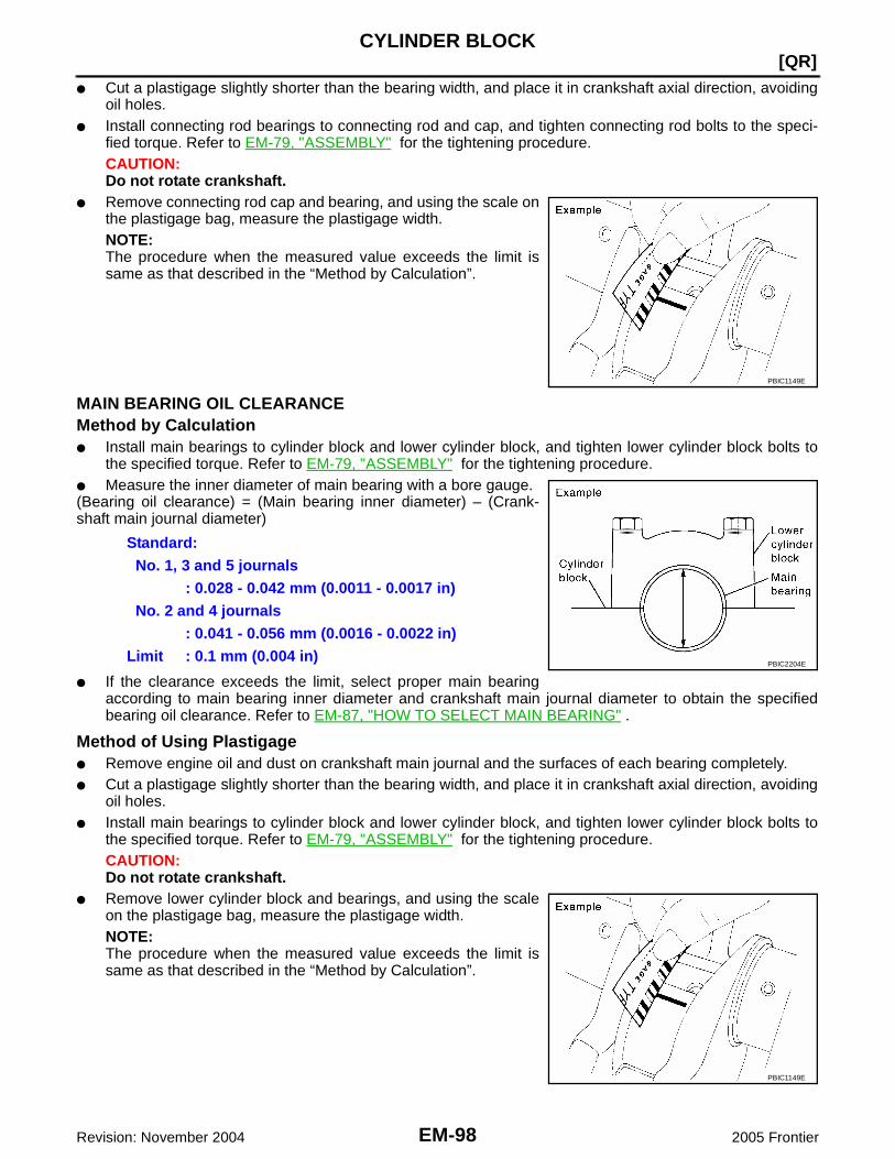
EM-98Revision: November 2004
[QR]CYLINDER BLOCK
2005 Frontier
● Cut a plastigage slightly shorter than the bearing width, and place it in crankshaft axial direction, avoidingoil holes.
● Install connecting rod bearings to connecting rod and cap, and tighten connecting rod bolts to the speci-fied torque. Refer to EM-79, "ASSEMBLY" for the tightening procedure.CAUTION:Do not rotate crankshaft.
● Remove connecting rod cap and bearing, and using the scale onthe plastigage bag, measure the plastigage width.NOTE:The procedure when the measured value exceeds the limit issame as that described in the “Method by Calculation”.
MAIN BEARING OIL CLEARANCEMethod by Calculation● Install main bearings to cylinder block and lower cylinder block, and tighten lower cylinder block bolts to
the specified torque. Refer to EM-79, "ASSEMBLY" for the tightening procedure.● Measure the inner diameter of main bearing with a bore gauge.(Bearing oil clearance) = (Main bearing inner diameter) – (Crank-shaft main journal diameter)
● If the clearance exceeds the limit, select proper main bearingaccording to main bearing inner diameter and crankshaft main journal diameter to obtain the specifiedbearing oil clearance. Refer to EM-87, "HOW TO SELECT MAIN BEARING" .
Method of Using Plastigage● Remove engine oil and dust on crankshaft main journal and the surfaces of each bearing completely.● Cut a plastigage slightly shorter than the bearing width, and place it in crankshaft axial direction, avoiding
oil holes.● Install main bearings to cylinder block and lower cylinder block, and tighten lower cylinder block bolts to
the specified torque. Refer to EM-79, "ASSEMBLY" for the tightening procedure.CAUTION:Do not rotate crankshaft.
● Remove lower cylinder block and bearings, and using the scaleon the plastigage bag, measure the plastigage width.NOTE:The procedure when the measured value exceeds the limit issame as that described in the “Method by Calculation”.
PBIC1149E
Standard:No. 1, 3 and 5 journals
: 0.028 - 0.042 mm (0.0011 - 0.0017 in)No. 2 and 4 journals
: 0.041 - 0.056 mm (0.0016 - 0.0022 in)Limit : 0.1 mm (0.004 in)
PBIC2204E
PBIC1149E

CYLINDER BLOCK
EM-99
[QR]
C
D
E
F
G
H
I
J
K
L
M
A
EM
Revision: November 2004 2005 Frontier
MAIN BEARING CRUSH HEIGHT● When lower cylinder block is removed after being tightened to
the specified torque with main bearings installed, the tip end ofbearing must protrude. Refer to EM-79, "ASSEMBLY" for thetightening procedure.
● If the standard is not met, replace main bearings.
CONNECTING ROD BEARING CRUSH HEIGHT● When connecting rod bearing cap is removed after being tight-
ened to the specified torque with connecting rod bearingsinstalled, the tip end of bearing must protrude. Refer to EM-79,"ASSEMBLY" for the tightening procedure.
● If the standard is not met, replace connecting rod bearings.
LOWER CYLINDER BLOCK MOUNTING BOLT OUTER DIAMETER● Perform only with M10 bolts.● Measure the outer diameters (“d1 ”, “d2” ) at two positions as
shown.● If reduction appears in “A” range, regard it as “d2 ”.
● If it exceeds the limit (a large difference in dimensions), replacelower cylinder block bolt with a new one.
CONNECTING ROD BOLT OUTER DIAMETER● Measure the outer diameter “d” at position as shown.● If reduction appears in a position other than “d”, regard it as “d”.
● When “d ” falls below the limit (when it becomes thinner),replace connecting rod bolt with a new one.
Standard: There must be crush height.
SEM502G
Standard: There must be crush height.
PBIC1646E
Limit (“d1 ” – “d2 ”): 0.13 mm (0.0051 in)
PBIC0911E
Limit: 7.75 mm (0.3051 in)
PBIC0912E

EM-100Revision: November 2004
[QR]CYLINDER BLOCK
2005 Frontier
FLYWHEEL DEFLECTION (M/T MODELS)● Measure the deflection of flywheel contact surface to clutch with
a dial indicator.● Measure the deflection at 250 mm (9.84 in) dia.
● If measured value is out of the standard, replace flywheel.CAUTION:When measuring, keep magnetic fields (such as dial indicatorstand) away from signal plate of the rear end of crankshaft.
MOVEMENT AMOUNT OF FLYWHEEL (M/T MODELS)CAUTION:Do not disassemble double mass flywheel.
Movement Amount of Thrust (Fore-and-Aft) Direction● Measure the movement amount of thrust (fore-and-aft) direction when 100 N (10.2 kg, 22 lb) force is
added at the portion of 125 mm (4.92 in) radius from the center of flywheel.
● If measured value is out of the standard, replace flywheel.
Movement Amount in Radial (Rotation) DirectionCheck the movement amount of radial (rotation) direction with the following procedure:1. Install a bolt to clutch cover mounting hole, and place a torque wrench on the extended line of the flywheel
center line.● Tighten bolt at a force of 9.8 N·m (1.0 kg-m, 87 in-lb) to keep it from loosening.
2. Put a mating mark on circumferences of the two flywheelmasses without applying any load (Measurement standardpoints).
3. Apply a force of 9.8 N·m (1.0 kg-m, 87 in-lb) in each direction,and mark the movement amount on the mass on the transmis-sion side.
4. Measure the dimensions of movement amounts “A” and “B” oncircumference of flywheel on the transmission side.
● If measured value is out of the standard, replace flywheel.
Standard : 0.45 mm (0.0177 in) or less.
PBIC2168E
Standard : 1.3 mm (0.051 in) or less
Standard: 44.3 mm (1.744 in) or less.PBIC1263E

SERVICE DATA AND SPECIFICATIONS (SDS)
EM-101
[QR]
C
D
E
F
G
H
I
J
K
L
M
A
EM
Revision: November 2004 2005 Frontier
SERVICE DATA AND SPECIFICATIONS (SDS) PFP:00030
Standard and Limit EBS00NIF
GENERAL SPECIFICATIONS
DRIVE BELT
EXHAUST MANIFOLD AND THREE WAY CATALYST ASSEMBLYUnit: mm (in)
SPARK PLUG
CYLINDER HEADUnit: mm (in)
Cylinder arrangement In-line 4
Displacement cm3 (cu in) 2,488 (151.82)
Bore and stroke mm (in) 89.0 x 100.0 (3.504 x 3.937)
Valve arrangement DOHC
Firing order 1-3-4-2
Number of piston ringsCompression 2
Oil 1
Compression ratio 9.5
Compression pressure
kPa (kg/cm2 , psi) / 250 rpm
Standard 1,304 (13.3, 189)
Minimum 1,108 (11.3, 161)
Differential limit between cylinders 100 (1.0, 14)
Tension of drive belt Auto adjustment by auto-tensioner
Item Limit
Surface distortion 0.3 (0.012)
Make NGK
Standard type PLZKAR6A–11
Hot type PLZKAR5A–11
Cold type PLZKAR7A–11
Gap (nominal) 1.1 mm (0.043 in)
Items Limit
Head surface distortion 0.1 (0.004)
PBIC0283E

EM-102Revision: November 2004
[QR]SERVICE DATA AND SPECIFICATIONS (SDS)
2005 Frontier
VALVEValve Timing
Valve DimensionsUnit: mm (in)
Valve ClearanceUnit: mm (in)
*: Approximately 80°C (176°F)
Valve timing
Unit: degree
a b c d e f
236 224 -4 60 32 37
PBIC0187E
Valve head diameter “D”Intake 35.5 - 35.8 (1.398 - 1.409)
Exhaust 30.5 - 30.8 (1.201 - 1.213)
Valve length “L”Intake 97.16 (3.8252)
Exhaust 98.82 (3.8905)
Valve stem diameter “d”Intake 5.965 - 5.980 (0.2348 - 0.2354)
Exhaust 5.955 - 5.970 (0.2344 - 0.2350)
Valve seat angle “α”Intake
45°15′ - 45°45′Exhaust
Valve margin “T”Intake 1.1 (0.043)
Exhaust 1.3 (0.051)
SEM188A
Items Cold Hot* (reference data)
Intake 0.24 - 0.32 (0.009 - 0.013) 0.304 - 0.416 (0.012 - 0.016)
Exhaust 0.26 - 0.34 (0.010 - 0.013) 0.308 - 0.432 (0.012 - 0.017)

SERVICE DATA AND SPECIFICATIONS (SDS)
EM-103
[QR]
C
D
E
F
G
H
I
J
K
L
M
A
EM
Revision: November 2004 2005 Frontier
Available Valve Lifter
Valve Spring
Thickness mm (in) Identification mark
6.96 (0.2740) 696
6.98 (0.2748) 698
7.00 (0.2756) 700
7.02 (0.2764) 702
7.04 (0.2772) 704
7.06 (0.2780) 706
7.08 (0.2787) 708
7.10 (0.2795) 710
7.12 (0.2803) 712
7.14 (0.2811) 714
7.16 (0.2819) 716
7.18 (0.2827) 718
7.20 (0.2835) 720
7.22 (0.2843) 722
7.24 (0.2850) 724
7.26 (0.2858) 726
7.28 (0.2866) 728
7.30 (0.2874) 730
7.32 (0.2882) 732
7.34 (0.2890) 734
7.36 (0.2898) 736
7.38 (0.2906) 738
7.40 (0.2913) 740
7.42 (0.2921) 742
7.44 (0.2929) 744
7.46 (0.2937) 746
KBIA0119E
Items Intake Exhaust
Free height 44.84 - 45.04 mm (1.7654 - 1.7732 in) 45.28 - 45.48 mm (1.7827 - 1.7905 in)
Installation height 35.30 mm (1.390 in) 35.30 mm (1.390 in)
Installation load 151 - 175 N (15.4 - 17.8 kg, 34 - 39 lb) 151 - 175 N (15.4 - 17.8 kg, 34 - 39 lb)
Height during valve open 24.94 mm (0.9819 in) 26.39 mm (1.0390 in)
Load with valve open 358 - 408 N (36.5 - 41.6 kg, 80 - 92 lb) 325 - 371 N (33.1 - 37.8 kg, 73 - 83 lb)
Identification color Blue Yellow

EM-104Revision: November 2004
[QR]SERVICE DATA AND SPECIFICATIONS (SDS)
2005 Frontier
Valve LifterUnit: mm (in)
Valve GuideUnit: mm (in)
Items Standard
Valve lifter outer diameter 33.965 - 33.980 (1.3372 - 1.3378)
Valve lifter hole diameter 34.000 - 34.021 (1.3386 - 1.3394)
Valve lifter clearance 0.020 - 0.056 (0.0008 - 0.0022)
Items Standard part Service part
Valve guide Outer diameter 10.023 - 10.034 (0.3946 - 0.3950) 10.223 - 10.234 (0.4025 - 0.4029)
Inner diameter (Finished size) 6.000 - 6.018 (0.2362 - 0.2369)
Cylinder head valve guide hole diameter 9.975 - 9.996 (0.3927 - 0.3935) 10.175 - 10.196 (0.4006 - 0.4014)
Interference fit of valve guide 0.027 - 0.059 (0.0011 - 0.0023)
Items Standard Limit
Valve guide clearanceIntake 0.020 - 0.053 (0.0008 - 0.0021) 0.08 (0.003)
Exhaust 0.030 - 0.063 (0.0012 - 0.0025) 0.09 (0.004)
Projection length “L”Intake 10.1 - 10.3 (0.398 - 0.406)
Exhaust 10.0 - 10.4 (0.394 - 0.409)
PBIC0184E

SERVICE DATA AND SPECIFICATIONS (SDS)
EM-105
[QR]
C
D
E
F
G
H
I
J
K
L
M
A
EM
Revision: November 2004 2005 Frontier
Valve SeatUnit: mm (in)
*1 : Diameter made by intersection point of conic angles α1 and α2
*2 : Diameter made by intersection point of conic angles α2 and α3
*3 : Machining data
Items Standard Oversize [0.5 (0.02)] (Service)
Cylinder head seat recess diameter “D”Intake 36.500 - 36.516 (1.4370 - 1.4376) 37.000 - 37.016 (1.4567 - 1.4573)
Exhaust 31.500 - 31.516 (1.2402 - 1.2408) 32.000 - 32.016(1.2598 - 1.2605)
Valve seat outer diameter “d”Intake 36.597 - 36.613 (1.4408 - 1.4415) 37.097 - 37.113 (1.4605 - 1.4611)
Exhaust 31.600 - 31.616 (1.2441 - 1.2447) 32.100 - 32.116 (1.2638 - 1.2644)
Valve seat interference fitIntake 0.081 - 0.113 (0.0032 - 0.0044)
Exhaust 0.084 - 0.116 (0.0033 - 0.0046)
Diameter “d1”*1Intake 33.5 (1.319)
Exhaust 28.0 (1.102)
Diameter “d2”*2Intake 35.1 - 35.3 (1.382 - 1.390)
Exhaust 29.9 - 30.1 (1.177 - 1.185)
Angle “α1”Intake 60°
Exhaust 60°
Angle “α2”Intake 88°45′ - 90°15′
Exhaust 88°45′ - 90°15′
Angle “α3”Intake 120°
Exhaust 120°
Contacting width “W”*3Intake 1.05 - 1.35 (0.0413 - 0.0531)
Exhaust 1.25 - 1.55 (0.0492 - 0.0610)
Height “h”Intake 5.9 - 6.0 (0.232 - 0.236) 5.0 - 5.1 (0.197 - 0.201)
Exhaust 5.9 - 6.0 (0.232 - 0.236) 4.91 - 5.01 (0.1933 - 0.1972)
Depth “H” 6.0 (0.236)
PBIC2745E
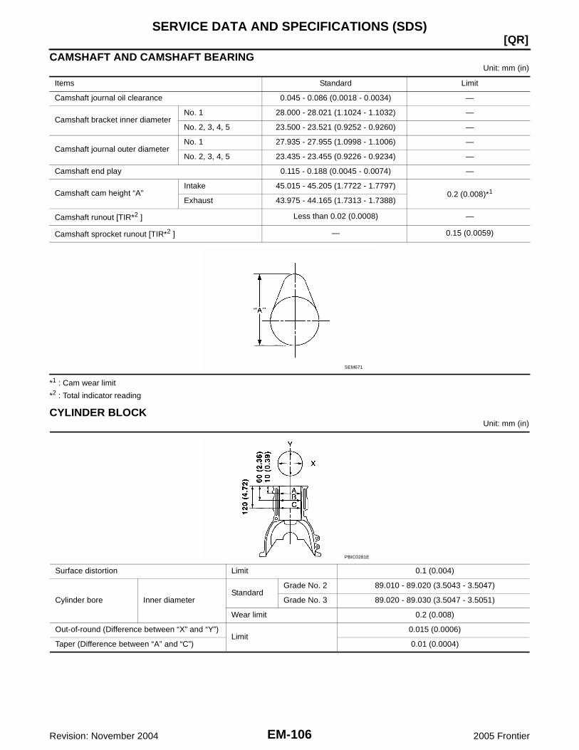
EM-106Revision: November 2004
[QR]SERVICE DATA AND SPECIFICATIONS (SDS)
2005 Frontier
CAMSHAFT AND CAMSHAFT BEARINGUnit: mm (in)
*1 : Cam wear limit
*2 : Total indicator reading
CYLINDER BLOCKUnit: mm (in)
Items Standard Limit
Camshaft journal oil clearance 0.045 - 0.086 (0.0018 - 0.0034) —
Camshaft bracket inner diameterNo. 1 28.000 - 28.021 (1.1024 - 1.1032) —
No. 2, 3, 4, 5 23.500 - 23.521 (0.9252 - 0.9260) —
Camshaft journal outer diameterNo. 1 27.935 - 27.955 (1.0998 - 1.1006) —
No. 2, 3, 4, 5 23.435 - 23.455 (0.9226 - 0.9234) —
Camshaft end play 0.115 - 0.188 (0.0045 - 0.0074) —
Camshaft cam height “A”Intake 45.015 - 45.205 (1.7722 - 1.7797)
0.2 (0.008)*1
Exhaust 43.975 - 44.165 (1.7313 - 1.7388)
Camshaft runout [TIR*2 ] Less than 0.02 (0.0008) —
Camshaft sprocket runout [TIR*2 ] — 0.15 (0.0059)
SEM671
Surface distortion Limit 0.1 (0.004)
Cylinder bore Inner diameterStandard
Grade No. 2 89.010 - 89.020 (3.5043 - 3.5047)
Grade No. 3 89.020 - 89.030 (3.5047 - 3.5051)
Wear limit 0.2 (0.008)
Out-of-round (Difference between “X” and “Y”)Limit
0.015 (0.0006)
Taper (Difference between “A” and “C”) 0.01 (0.0004)
PBIC0281E
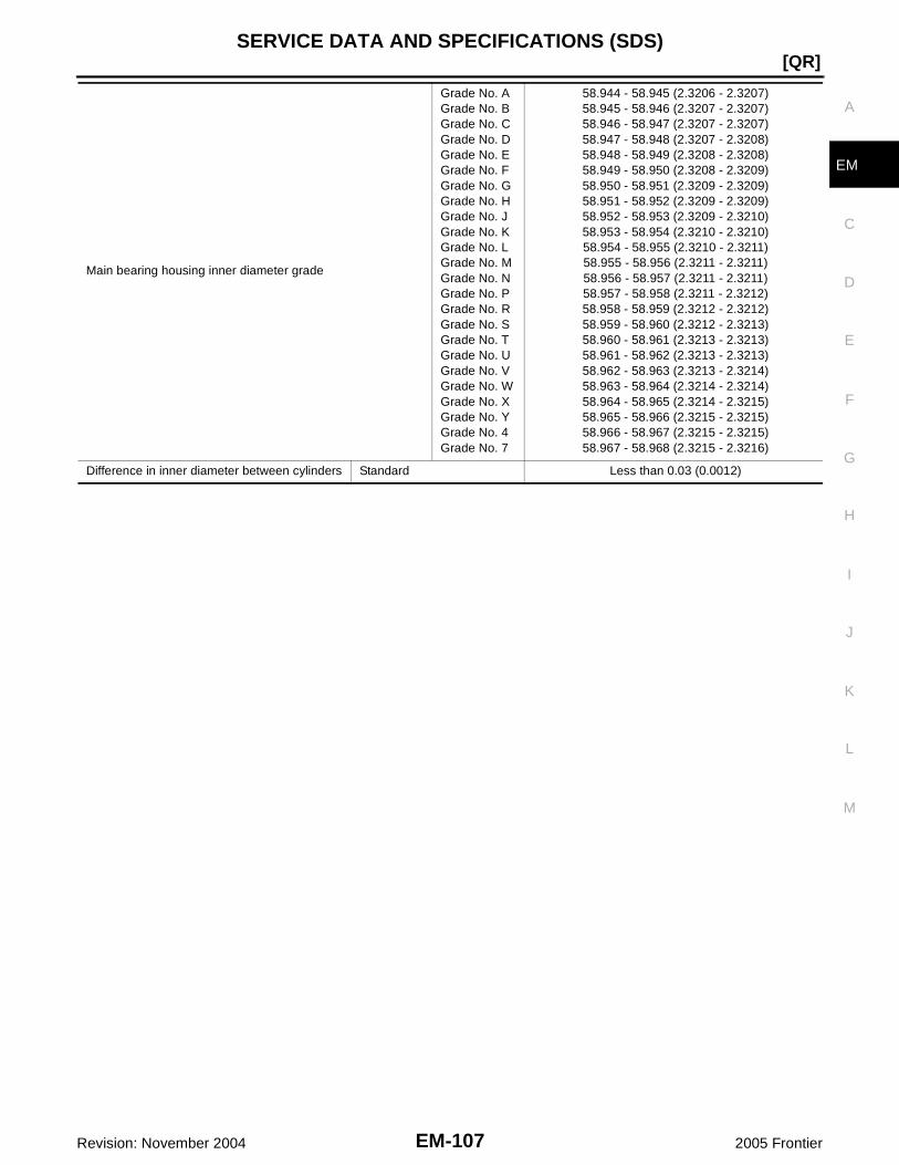
SERVICE DATA AND SPECIFICATIONS (SDS)
EM-107
[QR]
C
D
E
F
G
H
I
J
K
L
M
A
EM
Revision: November 2004 2005 Frontier
Main bearing housing inner diameter grade
Grade No. AGrade No. BGrade No. CGrade No. DGrade No. EGrade No. FGrade No. GGrade No. HGrade No. JGrade No. KGrade No. LGrade No. MGrade No. NGrade No. PGrade No. RGrade No. SGrade No. TGrade No. UGrade No. VGrade No. WGrade No. XGrade No. YGrade No. 4Grade No. 7
58.944 - 58.945 (2.3206 - 2.3207)58.945 - 58.946 (2.3207 - 2.3207)58.946 - 58.947 (2.3207 - 2.3207)58.947 - 58.948 (2.3207 - 2.3208)58.948 - 58.949 (2.3208 - 2.3208)58.949 - 58.950 (2.3208 - 2.3209)58.950 - 58.951 (2.3209 - 2.3209)58.951 - 58.952 (2.3209 - 2.3209)58.952 - 58.953 (2.3209 - 2.3210)58.953 - 58.954 (2.3210 - 2.3210)58.954 - 58.955 (2.3210 - 2.3211)58.955 - 58.956 (2.3211 - 2.3211)58.956 - 58.957 (2.3211 - 2.3211)58.957 - 58.958 (2.3211 - 2.3212)58.958 - 58.959 (2.3212 - 2.3212)58.959 - 58.960 (2.3212 - 2.3213)58.960 - 58.961 (2.3213 - 2.3213)58.961 - 58.962 (2.3213 - 2.3213)58.962 - 58.963 (2.3213 - 2.3214)58.963 - 58.964 (2.3214 - 2.3214)58.964 - 58.965 (2.3214 - 2.3215)58.965 - 58.966 (2.3215 - 2.3215)58.966 - 58.967 (2.3215 - 2.3215)58.967 - 58.968 (2.3215 - 2.3216)
Difference in inner diameter between cylinders Standard Less than 0.03 (0.0012)

EM-108Revision: November 2004
[QR]SERVICE DATA AND SPECIFICATIONS (SDS)
2005 Frontier
PISTON, PISTON RING AND PISTON PINAvailable Piston
Unit: mm (in)
Piston RingUnit: mm (in)
Piston PinUnit: mm (in)
Piston skirt diameter “A” Standard
Grade No. 2 88.990 - 89.000 (3.5035 - 3.5039)
Grade No. 3 89.000 - 89.010 (3.5039 - 3.5043)
0.20 (0.008) oversize (Service) 89.180 - 89.210 (3.5110 - 3.5122)
Piston height “H” dimension 42.98 (1.692)
Piston pin hole diameterGrade No. 0 19.993 - 19.999 (0.7871 - 0.7874)
Grade No. 1 19.999 - 20.005 (0.7874 - 0.7876)
Piston to cylinder bore clearanceStandard 0.010 - 0.030 (0.0004 - 0.0012)
Limit 0.08 (0.0031)
PBIC0188E
Items Standard Limit
Side clearance
Top 0.040 - 0.080 (0.0016 - 0.0031) 0.11 (0.0043)
2nd 0.030 - 0.070 (0.0012 - 0.0028) 0.10 (0.0039)
Oil ring (rail ring) 0.065 - 0.135 (0.0026 - 0.0053) —
End gap
Top 0.21- 0.31 (0.0083 - 0.0122) 0.54 (0.0213)
2nd 0.32 - 0.47 (0.0146 - 0.0205) 0.65 (0.0257)
Oil ring (rail ring) 0.20 - 0.60 (0.0079 - 0.0236) 0.95 (0.0374)
Piston pin outer diameterGrade No. 0 19.989 - 19.995 (0.7870 - 0.7872)
Grade No. 1 19.995 - 20.001 (0.7872 - 0.7874)
Piston to piston pin oil clearance Standard 0.002 - 0.006 (0.0001 - 0.0002)
Connecting rod bushing oil clearance Standard 0.005 - 0.017 (0.0002 - 0.0007)

SERVICE DATA AND SPECIFICATIONS (SDS)
EM-109
[QR]
C
D
E
F
G
H
I
J
K
L
M
A
EM
Revision: November 2004 2005 Frontier
CONNECTING RODUnit: mm (in)
*: After installing in connecting rod
CRANKSHAFTUnit: mm (in)
Center distance 143.00 - 143.10 (5.630 - 5.634)
Bend [per 100 (3.94)] Limit 0.15 (0.0059)
Torsion [per 100 (3.94)] Limit 0.30 (0.0118)
Connecting rod bushing inner diameter*Grade No. 0 20.000 - 20.006 (0.7874 - 0.7876)
Grade No. 1 20.006 - 20.012 (0.7876 - 0.7879)
Side clearanceStandard 0.20 - 0.35 (0.0079 - 0.0138)
Limit 0.50 (0.0197)
Connecting rod big end diameter
Grade No. 0Grade No. 1Grade No. 2Grade No. 3Grade No. 4Grade No. 5Grade No. 6Grade No. 7Grade No. 8Grade No. 9Grade No. AGrade No. BGrade No. C
48.000 - 48.001 (1.8898 - 1.8898)48.001 - 48.002 (1.8898 - 1.8898)48.002 - 48.003 (1.8898 - 1.8899)48.003 - 48.004 (1.8899 - 1.8899)48.004 - 48.005 (1.8899 - 1.8900)48.005 - 48.006 (1.8900 - 1.8900)48.006 - 48.007 (1.8900 - 1.8900)48.007 - 48.008 (1.8900 - 1.8901)48.008 - 48.009 (1.8901 - 1.8901)48.009 - 48.010 (1.8901 - 1.8902)48.010 - 48.011 (1.8902 - 1.8902)48.011 - 48.012 (1.8902 - 1.8902)48.012 - 48.013 (1.8902 - 1.8903)
Center distance “r” 49.96 - 50.04 (1.9669 - 1.9701)
Out-of-round (Difference between “X” and “Y”) Limit 0.0025 (0.0001)
Taper (Difference between “A” and “B”) Limit 0.0025 (0.0001)
Runout [TIR*] Limit 0.05 (0.0020)
Crankshaft end playStandard 0.10 - 0.26 (0.0039 - 0.0102)
Limit 0.30 (0.0118)
SEM645 SBIA0535E

EM-110Revision: November 2004
[QR]SERVICE DATA AND SPECIFICATIONS (SDS)
2005 Frontier
*: Total indicator reading
Pin journal diameter grade. “DP”
Grade No. AGrade No. BGrade No. CGrade No. DGrade No. EGrade No. FGrade No. GGrade No. HGrade No. JGrade No. KGrade No. LGrade No. MGrade No. NGrade No. PGrade No. RGrade No. SGrade No. TGrade No. U
44.974 - 44.973 (1.7706 - 1.7706)44.973 - 44.972 (1.7706 - 1.7705)44.972 - 44.971 (1.7705 - 1.7705)44.971 - 44.970 (1.7705 - 1.7705)44.970 - 44.969 (1.7705 - 1.7704)44.969 - 44.968 (1.7704 - 1.7704)44.968 - 44.967 (1.7704 - 1.7704)44.967 - 44.966 (1.7704 - 1.7703)44.966 - 44.965 (1.7703 - 1.7703)44.965 - 44.964 (1.7703 - 1.7702)44.964 - 44.963 (1.7702 - 1.7702)44.963 - 44.962 (1.7702 - 1.7702)44.962 - 44.961 (1.7702 - 1.7701)44.961 - 44.960 (1.7701 - 1.7701)44.960 - 44.959 (1.7701 - 1.7700)44.959 - 44.958 (1.7700 - 1.7700)44.958 - 44.957 (1.7700 - 1.7700)44.957 - 44.956 (1.7700 - 1.7699)
Main journal diameter grade. “Dm”
Grade No. AGrade No. BGrade No. CGrade No. DGrade No. EGrade No. FGrade No. GGrade No. HGrade No. JGrade No. KGrade No. LGrade No. MGrade No. NGrade No. PGrade No. RGrade No. SGrade No. TGrade No. UGrade No. VGrade No. WGrade No. XGrade No. YGrade No. 4Grade No. 7
54.979 - 54.978 (2.1645 - 2.1645)54.978 - 54.977 (2.1645 - 2.1644)54.977 - 54.976 (2.1644 - 2.1644)54.976 - 54.975 (2.1644 - 2.1644)54.975 - 54.974 (2.1644 - 2.1643)54.974 - 54.973 (2.1643 - 2.1643)54.973 - 54.972 (2.1643 - 2.1642)54.972 - 54.971 (2.1642 - 2.1642)54.971 - 54.970 (2.1642 - 2.1642)54.970 - 54.969 (2.1642 - 2.1641)54.969 - 54.968 (2.1641 - 2.1641)54.968 - 54.967 (2.1641 - 2.1641)54.967 - 54.966 (2.1641 - 2.1640)54.966 - 54.965 (2.1640 - 2.1640)54.965 - 54.964 (2.1640 - 2.1639)54.964 - 54.963 (2.1639 - 2.1639)54.963 - 54.962 (2.1639 - 2.1639)54.962 - 54.961 (2.1639 - 2.1638)54.961 - 54.960 (2.1638 - 2.1638)54.960 - 54.959 (2.1638 - 2.1637)54.959 - 54.958 (2.1637 - 2.1637)54.958 - 54.957 (2.1637 - 2.1637)54.957 - 54.956 (2.1637 - 2.1636)54.956 - 54.955 (2.1636 - 2.1636)

SERVICE DATA AND SPECIFICATIONS (SDS)
EM-111
[QR]
C
D
E
F
G
H
I
J
K
L
M
A
EM
Revision: November 2004 2005 Frontier
MAIN BEARINGUnit: mm (in)
UndersizeUnit: mm (in)
Bearing Oil ClearanceUnit: mm (in)
Grade number Thickness Identification color Remarks
0 1.973 - 1.976 (0.0777 - 0.0778) Black
Grade and color are the samefor upper and lower bearings.
1 1.976 - 1.979 (0.0778 - 0.0779) Brown
2 1.979 - 1.982 (0.0779 - 0.0780) Green
3 1.982 - 1.985 (0.0780 - 0.0781) Yellow
4 1.985 - 1.988 (0.0781 - 0.0783) Blue
5 1.988 - 1.991 (0.0783 - 0.0784) Pink
6 1.991 - 1.994 (0.0784 - 0.0785) Purple
7 1.994 - 1.997 (0.0785 - 0.0786) White
01UPR 1.973 - 1.976 (0.0777 - 0.0778) Black
Grade and color are differentfor upper and lower bearings.
LWR 1.976 - 1.979 (0.0778 - 0.0779) Brown
12UPR 1.976 - 1.979 (0.0778 - 0.0779) Brown
LWR 1.979 - 1.982 (0.0779 - 0.0780) Green
23UPR 1.979 - 1.982 (0.0779 - 0.0780) Green
LWR 1.982 - 1.985 (0.0780 - 0.0781) Yellow
34UPR 1.982 - 1.985 (0.0780 - 0.0781) Yellow
LWR 1.985 - 1.988 (0.0781 - 0.0783) Blue
45UPR 1.985 - 1.988 (0.0781 - 0.0783) Blue
LWR 1.988 - 1.991 (0.0783 - 0.0784) Pink
56UPR 1.988 - 1.991 (0.0783 - 0.0784) Pink
LWR 1.991 - 1.994 (0.0784 - 0.0785) Purple
67UPR 1.991 - 1.994 (0.0784 - 0.0785) Purple
LWR 1.994 - 1.997 (0.0785 - 0.0786) White
SEM685D
Item Thickness Main journal diameter
US 0.25 (0.0098) 2.106 - 2.114 (0.0829 - 0.0832) Grind so that bearing clearance is the specified value.
Main bearing oil clearanceStandard
No. 1, 3 and 5 0.028 - 0.042 (0.0011 - 0.0017)
No. 2 and 4 0.041 - 0.056 (0.0016 - 0.0022)
Limit 0.1 (0.004)

EM-112Revision: November 2004
[QR]SERVICE DATA AND SPECIFICATIONS (SDS)
2005 Frontier
CONNECTING ROD BEARING
UndersizeUnit: mm (in)
Bearing Oil ClearanceUnit: mm (in)
Grade number Thickness mm (in) Identification color
0 1.495 - 1.499 (0.0589 - 0.0590) Black
1 1.499 - 1.503 (0.0590 - 0.0592) Brown
2 1.503 - 1.507 (0.0592 - 0.0593) Green
3 1.507 - 1.511(0.0593 - 0.0595) Yellow
Item Thickness Crank pin journal diameter
US 0.25 (0.0098) 1.624 - 1.632 (0.0639 - 0.0643) Grind so that bearing clearance is the specified value.
Connecting rod bearing oil clearanceStandard 0.037 - 0.055 (0.0015 - 0.0022)
Limit 0.10 (0.0039)

PRECAUTIONS
EM-113
[VQ]
C
D
E
F
G
H
I
J
K
L
M
A
EM
Revision: November 2004 2005 Frontier
PRECAUTIONS PFP:00001
Precautions for Drain Engine Coolant EBS00P44
Drain engine coolant when engine is cooled.
Precautions for Disconnecting Fuel Piping EBS00P45
● Before starting work, make sure no fire or spark producing items are in the work area.● Release fuel pressure before disconnecting and disassembly.● After disconnecting pipes, plug openings to stop fuel leakage.
Precautions for Removal and Disassembly EBS00P46
● When instructed to use SST, use specified tools. Always be careful to work safely, avoid forceful or unin-structed operations.
● Exercise maximum care to avoid damage to mating or sliding surfaces.● Cover openings of engine system with tape or equivalent, if necessary, to seal out foreign materials.● Mark and arrange disassembly parts in an organized way for easy troubleshooting and re-assembly.● When loosening nuts and bolts, as a basic rule, start with the one furthest outside, then the one diagonally
opposite, and so on. If the order of loosening is specified, do exactly as specified. Power tools may beused in the step.
Precautions for Inspection, Repair and Replacement EBS00P47
Before repairing or replacing, thoroughly inspect parts. Inspect new replacement parts in the same way, andreplace if necessary.
Precautions for Assembly and Installation EBS00P48
● Use torque wrench to tighten bolts or nuts to specification.● When tightening nuts and bolts, as a basic rule, equally tighten in several different steps starting with the
ones in center, then ones on inside and outside diagonally in this order. If the order of tightening is speci-fied, do exactly as specified.
● Replace with new gasket, packing, oil seal or O-ring.● Thoroughly wash, clean, and air-blow each part. Carefully check engine oil or engine coolant passages for
any restriction and blockage.● Avoid damaging sliding or mating surfaces. Completely remove foreign materials such as cloth lint or dust.
Before assembly, oil sliding surfaces well.● Release air within route when refilling after draining engine coolant.● After repairing, start engine and increase engine speed to check engine coolant, fuel, engine oil, and
exhaust gasses for leakage.
Parts Requiring Angle Tightening EBS00P49
● For the final tightening of the following engine parts use Tool:
– Cylinder head bolts– Lower cylinder block bolts– Connecting rod cap bolts– Crankshaft pulley bolt (No angle wrench is required as bolt flange is provided with notches for angle tight-
ening)● Do not use a torque value for final tightening.● The torque value for these parts are for a preliminary step.● Ensure thread and seat surfaces are clean and coated with engine oil.
Tool number : KV10112100 (BT-8653-A)

EM-114Revision: November 2004
[VQ]PRECAUTIONS
2005 Frontier
Precautions for Liquid Gasket EBS00P4A
REMOVAL OF LIQUID GASKET SEALING● After removing nuts and bolts, separate the mating surface and
remove old liquid gasket sealing using Tool.
CAUTION:Be careful not to damage the mating surfaces.
● Tap seal cutter to insert it, and then slide it by tapping on theside as shown.
● In areas where Tool is difficult to use, use plastic hammer tolightly tap the parts, to remove it.CAUTION:If for some unavoidable reason tool such as screwdriver isused, be careful not to damage the mating surfaces.
LIQUID GASKET APPLICATION PROCEDURE1. Using scraper, remove old liquid gasket adhering to the gasket
application surface and the mating surface.● Remove liquid gasket completely from the groove of the gas-
ket application surface, bolts, and bolt holes.2. Thoroughly clean the mating surfaces and remove adhering
moisture, grease and foreign materials.
3. Attach liquid gasket tube to Tool.
Use Genuine RTV Silicone Sealant or equivalent. Refer toGI-45, "Recommended Chemical Products and Sealants" .
4. Apply liquid gasket without breaks to the specified location withthe specified dimensions.● If there is a groove for liquid gasket application, apply liquid
gasket to the groove.
● As for bolt holes, normally apply liquid gasket inside theholes. Occasionally, it should be applied outside the holes.Make sure to read the text of this manual.
● Within five minutes of liquid gasket application, install the mat-ing component.
● If liquid gasket protrudes, wipe it off immediately.● Do not retighten nuts or bolts after the installation.● After 30 minutes or more have passed from the installation, fill
engine oil and engine coolant.CAUTION:If there are specific instructions in this manual, observethem.
Tool number : KV10111100 (J-37228)
WBIA0566E
PBIC0003E
Tool number : WS39930000 ( — )
WBIA0567E
SEM159F

PREPARATION
EM-115
[VQ]
C
D
E
F
G
H
I
J
K
L
M
A
EM
Revision: November 2004 2005 Frontier
PREPARATION PFP:00002
Special Service Tools EBS00P4B
The actual shapes of Kent-Moore tools may differ from those of special service tools illustrated here.
Tool number(Kent-Moore No.)Tool name
Description
ST0501S000( — )Engine stand assembly1. ST05011000( — )Engine stand2. ST05012000( — )Base
Disassembling and assembling engine
KV10116200(J-26336-A)Valve spring compressor1. KV10115900(J-26336-20)Attachment2.KV10109220( — )Adapter
Disassembling valve mechanismPart (1) is a component of KV10116200 (J-26336-A), but Part (2) is not so.
KV10107902(J-38959)Valve oil seal puller
Replacing valve oil seal
—(J-39386)Valve oil seal drift
Installing valve oil seal
EM03470000(J-8037)Piston ring compressor
Installing piston assembly into cylinder bore
ST16610001(J-23907)Pilot bushing puller
Removing pilot converter (A/T models)
NT042
PBIC1650E
NT011
NT024
NT044
NT045

EM-116Revision: November 2004
[VQ]PREPARATION
2005 Frontier
KV10111100(J-37228)Seal cutter
Removing oil pan (lower and upper), front andrear timing chain case, etc.
WS39930000( — )Tube presser
Pressing the tube of liquid gasket
KV10112100(BT-8653-A)Angle wrench
Tightening bolts for bearing cap, cylinderhead, etc. in angle
—(J-44626)Air fuel sensor Socket
Loosening or tightening air fuel ratio A/F sen-sora: 22 mm (0.87 in)
KV10114400(J-38365)Heated oxygen sensor wrench
Loosening or tightening heated oxygen sen-sor 1a: 22 mm (0.87 in)
KV10117700(J-44716)Ring gear stopper
Removing and installing crankshaft pulley
—(J-45488)Quick connector release
Removing fuel tube quick connectors in en-gine room(Available in SEC. 164 of PARTS CATALOG:Part No. 16441 6N210)
Tool number(Kent-Moore No.)Tool name
Description
NT046
NT052
NT014
LBIA0444E
NT636
NT822
PBIC0198E

PREPARATION
EM-117
[VQ]
C
D
E
F
G
H
I
J
K
L
M
A
EM
Revision: November 2004 2005 Frontier
Commercial Service Tools EBS00P4C
(Kent-Moore No.)Tool name
Description
( — )Power tool
Loosening nuts and bolts
( — )TORX socket
Removing and installing flywheelSize: T55
(J-24239-01)Cylinder head bolt wrench
Loosening and tightening cylinder head bolt,and used with angle wrench [SST:KV10112100 (BT-8653-A)]a: 13 (0.51) dia.b: 12 (0.47)c: 10 (0.39)Unit: mm (in)
( — )Spark plug wrench
Removing and installing spark plug
( — )Valve seat cutter set
Finishing valve seat dimensions
( — )Piston ring expander
Removing and installing piston ring
( — )Valve guide drift
Removing and installing valve guideIntake and Exhaust:a: 9.5 mm (0.374 in) dia.b: 5.5 mm (0.217 in) dia.
PBIC0190E
PBIC1113E
NT583
NT047
NT048
NT030
NT015

EM-118Revision: November 2004
[VQ]PREPARATION
2005 Frontier
( — )Valve guide reamer
(1): Reaming valve guide inner hole(2): Reaming hole for oversize valve guideIntake and Exhaust:d1 : 6.0 mm (0.236 in) dia.d2 : 10.2 mm (0.402 in) dia.
(J-43897-18)(J-43897-12)Oxygen sensor thread cleaner
Reconditioning the exhaust system threadsbefore installing a new heated oxygen sensor(Use with anti-seize lubricant shown below.)a: J-43897-18 [18 mm (0.71 in) dia.] for zir-conia heated oxygen sensorb: J-43897-12 [12 mm (0.47 in) dia.] for tita-nia heated oxygen sensor
( — )Anti-seize lubricant (Permatex 133ARor equivalent meeting MIL specifica-tion MIL-A-907)
Lubricating oxygen sensor thread cleaningtool when reconditioning exhaust systemthreads
(Kent-Moore No.)Tool name
Description
NT016
AEM488
AEM489

NOISE, VIBRATION AND HARSHNESS (NVH) TROUBLESHOOTING
EM-119
[VQ]
C
D
E
F
G
H
I
J
K
L
M
A
EM
Revision: November 2004 2005 Frontier
NOISE, VIBRATION AND HARSHNESS (NVH) TROUBLESHOOTING PFP:00003
NVH Troubleshooting —Engine Noise EBS00P4D
PBIC2873E

EM-120Revision: November 2004
[VQ]NOISE, VIBRATION AND HARSHNESS (NVH) TROUBLESHOOTING
2005 Frontier
Use the Chart Below to Help You Find the Cause of the Symptom EBS00P4E
1. Locate the area where noise occurs.2. Confirm the type of noise.3. Specify the operating condition of engine.4. Check specified noise source.If necessary, repair or replace these parts.
A: Closely related B: Related C: Sometimes related —: Not related
Locationof noise
Type ofnoise
Operating condition of engine
Source ofnoise
Check itemRefer-
ence pageBeforewarm-
up
Afterwarm-
up
Whenstart-ing
Whenidling
Whenracing
Whiledriving
Top ofengineRockercoverCylinderhead
Ticking orclicking
C A — A B —Tappetnoise
Valve clearance EM-192
Rattle C A — A B CCamshaftbearingnoise
Camshaft runoutCamshaft journal oilclearance
EM-185EM-185
Crank-shaft pul-leyCylinderblock(Side ofengine)Oil pan
Slap orknock
— A — B B —Piston pinnoise
Piston to piston pin oilclearanceConnecting rod bush-ing oil clearance
EM-231EM-233
Slap orrap
A — — B B APistonslap noise
Piston to cylinder boreclearancePiston ring side clear-ancePiston ring end gapConnecting rod bendand torsion
EM-235EM-232EM-232EM-233
Knock A B C B B B
Connect-ing rodbearingnoise
Connecting rod bush-ing oil clearanceConnecting rod bear-ing oil clearance
EM-233EM-237
Knock A B — A B CMainbearingnoise
Main bearing oil clear-anceCrankshaft runout
EM-238EM-237
Front ofengineTimingchaincase
Tapping orticking
A A — B B B
Timingchain andchain ten-sionernoise
Timing chain cracksand wearTiming chain tensioneroperation
EM-171EM-163
Front ofengine
Squeak-ing or fizz-ing
A B — B — C
Drive belts(Stickingor slip-ping)
Drive belts deflection
EM-122
Creaking A B A B A BDrive belts(Slipping)
Idler pulley bearingoperation
SquallCreak
A B — B A BWaterpumpnoise
Water pump operation CO-38

ENGINE ROOM COVER
EM-121
[VQ]
C
D
E
F
G
H
I
J
K
L
M
A
EM
Revision: November 2004 2005 Frontier
ENGINE ROOM COVER PFP:14049
Removal and Installation EBS00P4F
REMOVAL1. Remove bolts using power tool.2. Lift up on engine cover firmly to dislodge snap fit mounts.
CAUTION:Do not damage or scratch cover when installing or remov-ing.
INSTALLATIONInstallation is in the reverse order of removal.
WBIA0622E

EM-122Revision: November 2004
[VQ]DRIVE BELTS
2005 Frontier
DRIVE BELTS PFP:02117
Checking Drive Belts EBS00P4G
WARNING:Be sure to perform when the engine is stopped.1. Remove air duct and resonator assembly (inlet) when inspecting drive belt. Refer to EM-124, "REMOVAL"
.2. Visually check entire belt for wear, damage or cracks.
Tension Adjustment EBS00P4H
Belt tensioning is not necessary, as it is automatically adjusted by auto tensioner.
Removal and Installation EBS00P4I
DRIVE BELTRemoval1. Remove air duct and resonator assembly (inlet). Refer to EM-124, "REMOVAL" .2. Rotate the drive belt auto tensioner in the direction of arrow
(loosening direction of tensioner) as shown, using suitable tool.CAUTION:Avoid placing hand in a location where pinching may occurif the tool accidentally comes off.
3. Remove the drive belt.
LBIA0427E
1. Drive belt 2. Power steering oil pump pulley 3. Generator pulley
4. Crankshaft pulley 5. A/C compressor 6. Cooling fan pulley
7. Idler pulley 8. Drive belt tensioner
LBIA0428E

DRIVE BELTS
EM-123
[VQ]
C
D
E
F
G
H
I
J
K
L
M
A
EM
Revision: November 2004 2005 Frontier
INSTALLATIONInstallation is in the reverse order of removal.CAUTION:Make sure belt is securely installed around all pulleys.
Drive Belt Auto Tensioner and Idler Pulley EBS00P4J
REMOVAL1. Remove air duct and resonator assembly (inlet). Refer to EM-124, "REMOVAL" .2. Remove drive belt. Refer to EM-122, "Removal" .3. Remove radiator cooling fan assembly. Refer to CO-36, "REMOVAL" .4. Remove auto tensioner and idler pulley using power tool.
INSTALLATIONInstallation is in the reverse order of removal.
LBIA0429E
1. Idler pulley 2. Drive belt auto tensioner

EM-124Revision: November 2004
[VQ]AIR CLEANER AND AIR DUCT
2005 Frontier
AIR CLEANER AND AIR DUCT PFP:16500
Removal and Installation EBS00P4K
REMOVAL1. Disconnect harness connector from mass air flow sensor.2. Disconnect PCV hose.3. Remove air cleaner case/mass air flow sensor assembly and air duct assembly disconnecting their joints.
● Add marks as necessary for easier installation.CAUTION:Handle mass air flow sensor with care.● Do not shock it.● Do not disassemble it.● Do not touch its sensor.
INSPECTION AFTER REMOVALInspect air duct for crack or tear.● If anything found, replace air duct.
INSTALLATIONInstallation is in the reverse order of removal.● Align marks. Attach each joint. Screw clamps firmly.
Changing Air Cleaner Filter EBS00P4L
REMOVAL1. Unhook clips, and lift air cleaner case (upper).2. Remove air cleaner filter.
INSTALLATIONInstallation is in the reverse order of removal.
1. Air duct and resonator 2. Air cleaner case (upper) 3. Air cleaner filter
4. Air cleaner case (lower)
WBIA0623E

INTAKE MANIFOLD COLLECTOR
EM-125
[VQ]
C
D
E
F
G
H
I
J
K
L
M
A
EM
Revision: November 2004 2005 Frontier
INTAKE MANIFOLD COLLECTOR PFP:14003
Removal and Installation EBS00P4M
1. Vacuum tank 2. VIAS control solenoid valve 3. Vacuum hose
4. Intake manifold collector support 5. Water hose 6. Electric throttle control actuator
7. Water hose 8. EVAP hose 9. Bracket
10. EVAP hose 11.EVAP canister purge volume controlsolenoid valve
12. Gasket
13. Gasket 14. Intake manifold collector 15. Clip
16. PCV hose 17. Connector 18. PCV hose
PBIC2874E

EM-126Revision: November 2004
[VQ]INTAKE MANIFOLD COLLECTOR
2005 Frontier
REMOVALWARNING:To avoid the danger of being scalded, never drain engine coolant when engine is hot.1. Remove engine cover. Refer to EM-121, "REMOVAL" .2. Remove air cleaner case (upper) with mass air flow sensor and air duct assembly. Refer to EM-124,
"REMOVAL" .3. Remove electric throttle control actuator as follows:a. Drain engine coolant, or when water hoses are disconnected, attach plug to prevent engine coolant leak-
age. Refer to MA-21, "Changing Engine Coolant" .CAUTION:● Perform when engine is cold.● Do not spill engine coolant on drive belt.
b. Disconnect water hoses from electric throttle control actuator.● When engine coolant is not drained from radiator, attach plug to water hoses to prevent engine coolant
leakage.c. Disconnect harness connector.d. Loosen bolts in reverse order as shown.
CAUTION:● Handle carefully to avoid any shock to electric throttle
control actuator.● Do not disassemble.
4. Remove the following parts:● Vacuum hose (to brake booster)● PCV hose
5. Loosen bolts in reverse order as shown to remove intake mani-fold collector support.
6. Disconnect EVAP hoses and harness connector from EVAP canister purge volume control solenoid valve.7. Remove EVAP canister purge volume control solenoid valve.8. Remove VIAS control solenoid valve and vacuum tank.
● Add mating marks as necessary for easier installation.
PBIC2875E
PBIC2876E

INTAKE MANIFOLD COLLECTOR
EM-127
[VQ]
C
D
E
F
G
H
I
J
K
L
M
A
EM
Revision: November 2004 2005 Frontier
9. Loosen nuts and bolts in reverse order as shown with powertool, and remove intake manifold collector.CAUTION:Cover engine openings to avoid entry of foreign materials.
INSTALLATIONInstallation is in the reverse order of removal. Note the following:
Intake Manifold Collector● If stud bolts were removed from intake manifold, install them and tighten to the specified torque.● Tighten nuts and bolts in numerical order as shown.
Electric Throttle Control Actuator● Tighten bolts in numerical order as shown.● Perform the “Throttle Valve Closed Position Learning” when har-
ness connector of electric throttle control actuator is discon-nected. Refer to EC-705, "Throttle Valve Closed PositionLearning" .
● Perform the “Idle Air Volume Learning” and “Throttle ValveClosed Position Learning” when electric throttle control actuatoris replaced. Refer to EC-706, "Idle Air Volume Learning" .
PBIC2877E
Intake manifold collectorbolts and nuts
: 11.0 N·m (1.1 kg-m, 8 ft-lb)
Stud bolts : 6.9 N·m (7.0kg-m, 61 in-lb)
PBIC2877E
PBIC2875E

EM-128Revision: November 2004
[VQ]INTAKE MANIFOLD
2005 Frontier
INTAKE MANIFOLD PFP:14003
Removal and Installation EBS00P4N
REMOVAL1. Release fuel pressure. Refer to EC-708, "FUEL PRESSURE RELEASE" .2. Remove intake manifold collector. Refer to EM-126, "REMOVAL" .3. Remove fuel tube and fuel injector assembly. Refer to EM-143, "REMOVAL" .4. Loosen nuts and bolts with power tool in reverse order as shown
to remove intake manifold.
5. Remove gaskets.CAUTION:Cover engine openings to avoid entry of foreign materials.
INSPECTION AFTER REMOVALSurface Distortion● Check the surface distortion of the intake manifold mating sur-
face with straightedge and feeler gauge.
● If it exceeds the limit, replace intake manifold.
1. Intake manifold 2. Gasket
PBIC2878E
PBIC2879E
Limit : 0.1 mm (0.004 in)
PBIC0870E

INTAKE MANIFOLD
EM-129
[VQ]
C
D
E
F
G
H
I
J
K
L
M
A
EM
Revision: November 2004 2005 Frontier
INSTALLATIONInstallation is in the reverse order of removal. Note the following:
Intake Manifold● If stud bolts were removed from cylinder head, install them and tighten to the specified torque.
● Tighten all nuts and bolts to the specified torque in two or moresteps in numerical order as shown.
Intake manifold studs : 11.0 N·m (1.1kg-m, 8 ft-lb)
Intake manifold bolt and nuts1st step : 7.4 N·m (0.75 kg-m, 5 ft-lb)2nd step and after : 29.0 N·m (3.0 kg-m, 21 ft-lb)
PBIC2879E

EM-130Revision: November 2004
[VQ]EXHAUST MANIFOLD AND THREE WAY CATALYST
2005 Frontier
EXHAUST MANIFOLD AND THREE WAY CATALYST PFP:14004
Removal and Installation EBS00P4O
REMOVAL (LEFT BANK)1. Remove air cleaner case and air duct. Refer to EM-124, "REMOVAL" .2. Remove engine undercover with power tool.3. Disconnect harness connector and remove heated oxygen sen-
sor 2 on both banks using Tool.
CAUTION:● Be careful not to damage heated oxygen sensor 2.● Discard any heated oxygen sensor 2 which has been
dropped from a height of more than 0.5 m (19.7 in) onto ahard surface such as a concrete floor; replace with a newsensor.
4. Remove center exhaust tube, main muffler and left front exhaust tube. Refer to EX-5, "REMOVAL" .5. Remove exhaust manifold cover (left bank).
1. Exhaust manifold cover (right bank) 2. Exhaust manifold (right bank) 3. Gasket
4. Exhaust manifold cover (left bank) 5. Exhaust manifold (left bank)
PBIC2880E
Tool number : KV10114400 (J-38365)
LBIA0446E
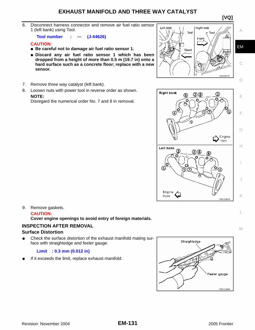
EXHAUST MANIFOLD AND THREE WAY CATALYST
EM-131
[VQ]
C
D
E
F
G
H
I
J
K
L
M
A
EM
Revision: November 2004 2005 Frontier
6. Disconnect harness connector and remove air fuel ratio sensor1 (left bank) using Tool.
CAUTION:● Be careful not to damage air fuel ratio sensor 1.● Discard any air fuel ratio sensor 1 which has been
dropped from a height of more than 0.5 m (19.7 in) onto ahard surface such as a concrete floor; replace with a newsensor.
7. Remove three way catalyst (left bank).8. Loosen nuts with power tool in reverse order as shown.
NOTE:Disregard the numerical order No. 7 and 8 in removal.
9. Remove gaskets.CAUTION:Cover engine openings to avoid entry of foreign materials.
INSPECTION AFTER REMOVALSurface Distortion● Check the surface distortion of the exhaust manifold mating sur-
face with straightedge and feeler gauge.
● If it exceeds the limit, replace exhaust manifold.
Tool number : — (J-44626)
LBIA0447E
PBIC2881E
Limit : 0.3 mm (0.012 in)
PBIC1096E

EM-132Revision: November 2004
[VQ]EXHAUST MANIFOLD AND THREE WAY CATALYST
2005 Frontier
INSTALLATION (LEFT BANK)Installation of the remaining components is in the reverse order of removal. Note the following:
Exhaust Manifold GasketInstall in direction as shown.
Exhaust Manifold● If stud bolts were removed, install them and tighten to the specified torque.
● Install exhaust manifold and tighten nuts in numerical order asshown.NOTE:Tighten nuts No. 1 and 2 in two steps. The numerical order No. 7and 8 shown second step.
Heated Oxygen SensorCAUTION:● Before installing a new air fuel ratio sensor 1 and heated oxygen sensor 2, clean exhaust system
threads using oxygen sensor thread cleaner and apply anti-seize lubricant.
● Do not over torque air fuel ratio sensor 1 and heated oxygen sensor 2. Doing so may cause dam-age to air fuel ratio sensor 1 and heated oxygen sensor 2, resulting in the “MIL” coming on.
PBIC2882E
Exhaust manifold stud torque : 14.7 N·m (1.5 kg-m, 11 ft-lb)
PBIC2881E
Tool number : ( — ) J-43897-12: ( — ) J-43897 18

EXHAUST MANIFOLD AND THREE WAY CATALYST
EM-133
[VQ]
C
D
E
F
G
H
I
J
K
L
M
A
EM
Revision: November 2004 2005 Frontier
REMOVAL (RIGHT BANK)1. Remove engine assembly. Refer to EM-213, "REMOVAL" .2. Loosen nuts with power tool in reverse order as shown.
NOTE:Disregard the numerical order No. 7 and 8 in removal.
3. Remove gaskets.CAUTION:Cover engine openings to avoid entry of foreign materials.
INSPECTION AFTER REMOVALSurface Distortion● Check the surface distortion of the exhaust manifold mating sur-
face with straightedge and feeler gauge.
● If it exceeds the limit, replace exhaust manifold.
PBIC2881E
Limit : 0.3 mm (0.012 in)
PBIC1096E

EM-134Revision: November 2004
[VQ]EXHAUST MANIFOLD AND THREE WAY CATALYST
2005 Frontier
INSTALLATION (RIGHT BANK)Installation of the remaining components is in the reverse order of removal. Note the following:
Exhaust Manifold GasketInstall in direction as shown.
Exhaust Manifold● If stud bolts were removed, install them and tighten to the specified torque.
● Install exhaust manifold and tighten nuts in numerical order asshown.NOTE:Tighten nuts No. 1 and 2 in two steps. The numerical order No. 7and 8 shown second step.
Heated Oxygen SensorCAUTION:● Before installing a new air fuel ratio sensor 1 and heated oxygen sensor 2, clean exhaust system
threads using oxygen sensor thread cleaner and apply anti-seize lubricant.
● Do not over torque air fuel ratio sensor 1 and heated oxygen sensor 2. Doing so may cause dam-age to air fuel ratio sensor 1 and heated oxygen sensor 2, resulting in the “MIL” coming on.
PBIC2882E
Exhaust manifold stud torque : 14.7 N·m (1.5 kg-m, 11 ft-lb)
PBIC2881E
Tool number : ( — ) J-43897-12: ( — ) J-43897 18

OIL PAN AND OIL STRAINER
EM-135
[VQ]
C
D
E
F
G
H
I
J
K
L
M
A
EM
Revision: November 2004 2005 Frontier
OIL PAN AND OIL STRAINER PFP:11110
Removal and Installation EBS00P4P
REMOVAL (LOWER)WARNING:To avoid the danger of being scalded, do not drain engine oil when engine is hot.1. Drain engine oil. Refer to MA-25, "Changing Engine Oil" .2. Remove oil pan (lower) as follows:a. Loosen bolts with power tool in reverse order as shown to
remove.
1. Oil pan (upper) 2. Oil pressure sensor 3. O-ring
4. Relief valve 5. O-ring 6. Oil cooler
7. Connector bolt 8. Oil filter 9. Drain plug
10. Drain plug washer 11. Oil pan (lower) 12. Rear cover plate
13. Oil strainer 14 O-ring 15. Oil level gauge guide
16. Oil level gauge
PBIC2883E
PBIC2890E
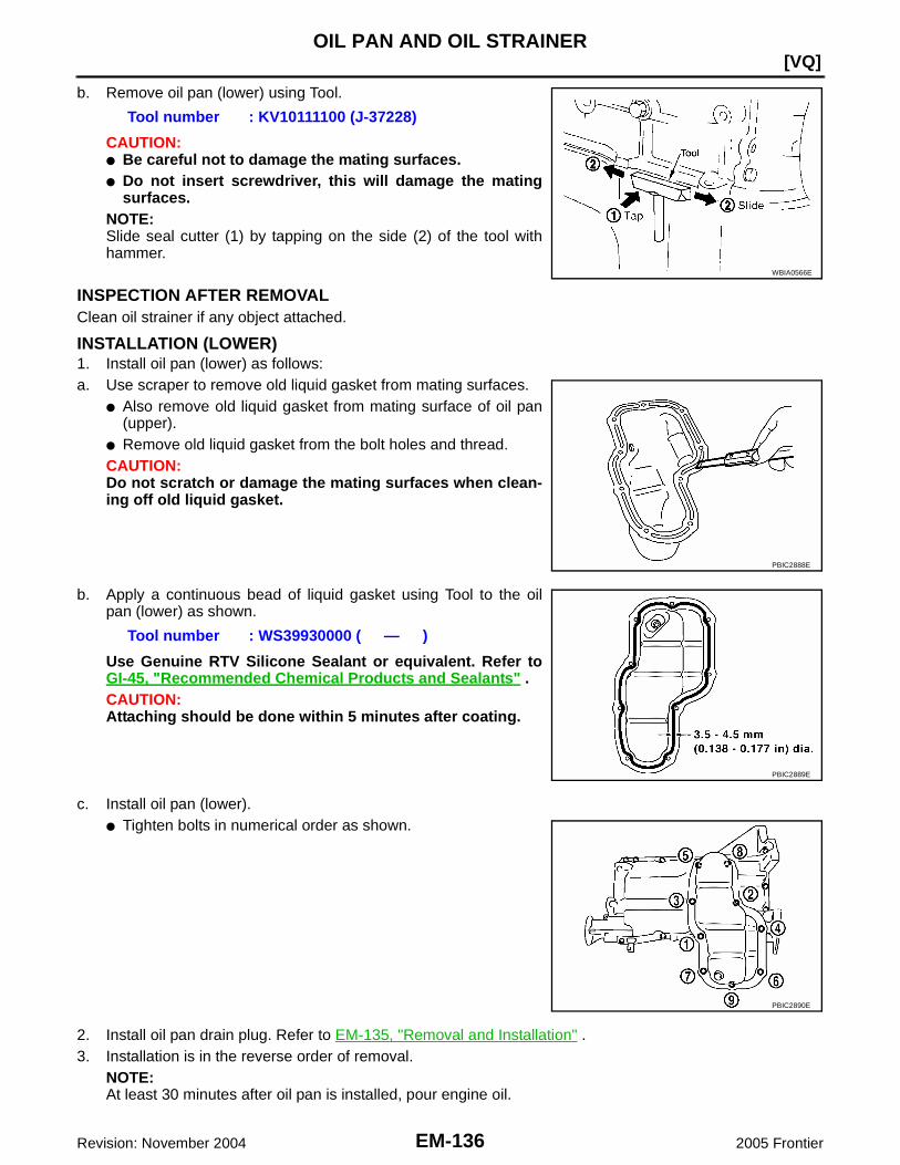
EM-136Revision: November 2004
[VQ]OIL PAN AND OIL STRAINER
2005 Frontier
b. Remove oil pan (lower) using Tool.
CAUTION:● Be careful not to damage the mating surfaces.● Do not insert screwdriver, this will damage the mating
surfaces.NOTE:Slide seal cutter (1) by tapping on the side (2) of the tool withhammer.
INSPECTION AFTER REMOVALClean oil strainer if any object attached.
INSTALLATION (LOWER)1. Install oil pan (lower) as follows:a. Use scraper to remove old liquid gasket from mating surfaces.
● Also remove old liquid gasket from mating surface of oil pan(upper).
● Remove old liquid gasket from the bolt holes and thread.CAUTION:Do not scratch or damage the mating surfaces when clean-ing off old liquid gasket.
b. Apply a continuous bead of liquid gasket using Tool to the oilpan (lower) as shown.
Use Genuine RTV Silicone Sealant or equivalent. Refer toGI-45, "Recommended Chemical Products and Sealants" .CAUTION:Attaching should be done within 5 minutes after coating.
c. Install oil pan (lower).● Tighten bolts in numerical order as shown.
2. Install oil pan drain plug. Refer to EM-135, "Removal and Installation" .3. Installation is in the reverse order of removal.
NOTE:At least 30 minutes after oil pan is installed, pour engine oil.
Tool number : KV10111100 (J-37228)
WBIA0566E
PBIC2888E
Tool number : WS39930000 ( — )
PBIC2889E
PBIC2890E

OIL PAN AND OIL STRAINER
EM-137
[VQ]
C
D
E
F
G
H
I
J
K
L
M
A
EM
Revision: November 2004 2005 Frontier
INSPECTION AFTER INSTALLATION1. Check engine oil level and adjust engine oil. Refer to LU-18, "ENGINE OIL" .2. Start engine, and check there is no leak of engine oil.3. Stop engine and wait for 10 minutes.4. Check engine oil level again. Refer to LU-18, "ENGINE OIL" .
REMOVAL (UPPER)WARNING:To avoid the danger of being scalded, do not drain engine oil when engine is hot.1. Remove engine cover with power tool. Refer to EM-121, "REMOVAL" .2. Remove air duct. Refer to EM-124, "REMOVAL" .3. Drain engine oil. Refer to LU-20, "Changing Engine Oil" .
CAUTION:● Perform this step when engine is cold.● Do not spill engine oil on drive belts.
4. Drain engine coolant. Refer to MA-21, "Changing Engine Coolant" .CAUTION:● Perform this step when engine is cold.● Do not spill engine coolant on drive belts.
5. Remove front final drive (4X4). Refer to FFD-14, "REMOVAL" .6. Disconnect steering gear lower joint shaft bolt and steering gear nuts and bolts, position out of the way.
Refer to PS-15, "REMOVAL" .7. Remove starter motor. Refer to SC-23, "REMOVAL" .8. Disconnect A/T fluid cooler tube brackets and position out of the way. Refer to EM-22, "REMOVAL" .9. Remove oil filter, as necessary. Refer to LU-21, "REMOVAL" .10. Remove oil cooler. Refer to LU-22, "REMOVAL" .11. Remove oil pan (lower). Refer to EM-135, "REMOVAL (Lower)" .12. Remove oil strainer.13. Remove transmission joint bolts which pierce oil pan (upper).14. Remove rear cover plate.15. Loosen bolts with power tool in reverse order as shown.
● Insert Tool between oil pan (upper) and lower cylinder block.Slide Tool by tapping on the side of Tool with hammer.Remove oil pan (upper).
CAUTION:Be careful not to damage mating surfaces.
PBIC2887E
Tool number : KV10111100 (J-37228)
WBIA0566E
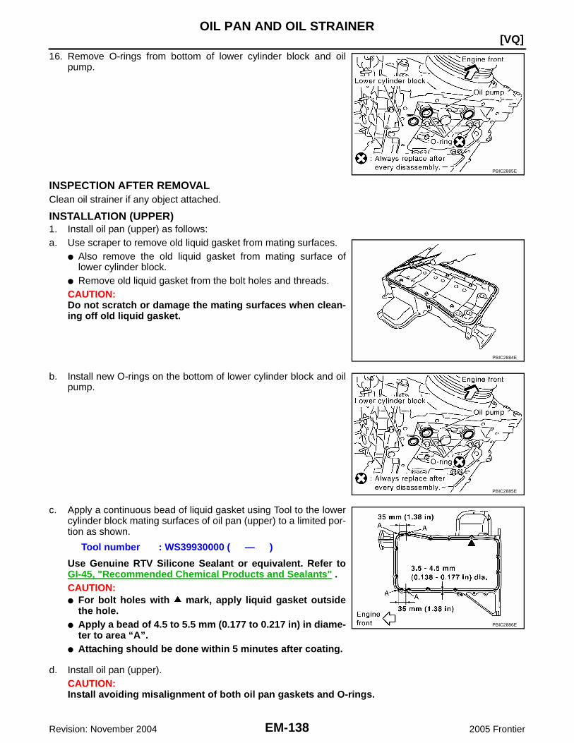
EM-138Revision: November 2004
[VQ]OIL PAN AND OIL STRAINER
2005 Frontier
16. Remove O-rings from bottom of lower cylinder block and oilpump.
INSPECTION AFTER REMOVALClean oil strainer if any object attached.
INSTALLATION (UPPER)1. Install oil pan (upper) as follows:a. Use scraper to remove old liquid gasket from mating surfaces.
● Also remove the old liquid gasket from mating surface oflower cylinder block.
● Remove old liquid gasket from the bolt holes and threads.CAUTION:Do not scratch or damage the mating surfaces when clean-ing off old liquid gasket.
b. Install new O-rings on the bottom of lower cylinder block and oilpump.
c. Apply a continuous bead of liquid gasket using Tool to the lowercylinder block mating surfaces of oil pan (upper) to a limited por-tion as shown.
Use Genuine RTV Silicone Sealant or equivalent. Refer toGI-45, "Recommended Chemical Products and Sealants" .CAUTION:● For bolt holes with mark, apply liquid gasket outside
the hole.● Apply a bead of 4.5 to 5.5 mm (0.177 to 0.217 in) in diame-
ter to area “A”.● Attaching should be done within 5 minutes after coating.
d. Install oil pan (upper).CAUTION:Install avoiding misalignment of both oil pan gaskets and O-rings.
PBIC2885E
PBIC2884E
PBIC2885E
Tool number : WS39930000 ( — )
PBIC2886E

OIL PAN AND OIL STRAINER
EM-139
[VQ]
C
D
E
F
G
H
I
J
K
L
M
A
EM
Revision: November 2004 2005 Frontier
● Tighten bolts in numerical order as shown.● There are two types of bolts. Refer to the following for locating
bolts.
e. Tighten transmission joint bolts. Refer to MT-16, "REMOVAL" (FS5R30A), MT-65, "REMOVAL"(FS6R31A) (4X2), MT-67, "REMOVAL" (FS6R31A) (4X4), AT-245, "REMOVAL" (A/T) (4X2), AT-249,"REMOVAL" (A/T) (4X4).
2. Install oil strainer to oil pan (upper).3. Installation of the remaining components is in the reverse order of removal.
INSPECTION AFTER INSTALLATION1. Check engine oil level and adjust engine oil. Refer to LU-18, "ENGINE OIL" .2. Start engine, and check there is no leak of engine oil.3. Stop engine and wait for 10 minutes.4. Check engine oil level again. Refer to LU-18, "ENGINE OIL" .
M8 × 100 mm (3.97 in) : 7, 11, 12, 13M8 × 25 mm (0.98 in) : Except the above
PBIC2887E

EM-140Revision: November 2004
[VQ]IGNITION COIL
2005 Frontier
IGNITION COIL PFP:22448
Removal and Installation EBS00P4Q
REMOVAL (LEFT BANK)1. Remove engine cover with power tool. Refer to EM-121, "REMOVAL" .2. Remove air cleaner case and air duct. (At the left bank side, remove ignition coil) Refer to EM-124,
"REMOVAL" .3. Move aside harness, harness bracket, and hoses located above ignition coil.4. Disconnect harness connector from ignition coil.5. Remove ignition coil.
CAUTION:Do not shock it.
INSTALLATION (LEFT BANK)Installation is in the reverse order of removal.
REMOVAL (RIGHT BANK)1. Remove intake manifold collector with power tool. Refer to EM-126, "REMOVAL" .2. Move aside harness, harness bracket, and hoses located above ignition coil.3. Disconnect harness connector from ignition coil.4. Remove ignition coil.
CAUTION:Do not shock it.
INSTALLATION (RIGHT BANK)Installation is in the reverse order of removal.
1. Ignition coil 2. Spark plug
PBIC2901E

SPARK PLUG (PLATINUM-TIPPED TYPE)
EM-141
[VQ]
C
D
E
F
G
H
I
J
K
L
M
A
EM
Revision: November 2004 2005 Frontier
SPARK PLUG (PLATINUM-TIPPED TYPE) PFP:22401
Removal and Installation EBS00P4R
REMOVAL1. Remove ignition coil. Refer to EM-140, "Removal and Installation" .2. Remove spark plug using spark plug wrench (commercial ser-
vice tool).CAUTION:Do not drop or shock it.
INSPECTION AFTER REMOVALUse standard type spark plug for normal condition.Hot type spark plug is suitable when fouling occurs with standard type spark plug under conditions such as:● Frequent engine starts● Low ambient temperaturesCold type spark plug is suitable when spark plug knock occurs with standard type spark plug under conditionssuch as:● Extended highway driving● Frequent high engine revolution
CAUTION:● Do not drop or shock spark plug.
1. Ignition coil 2. Spark plug
PBIC2901E
SEM294A
Make NGK
Standard type PLFR5A-11
Hot type PLFR4A-11
Cold type PLFR6A-11
Gap (Nominal) : 1.1 mm (0.043 in)

EM-142Revision: November 2004
[VQ]SPARK PLUG (PLATINUM-TIPPED TYPE)
2005 Frontier
● Do not use wire brush for cleaning.● If plug tip is covered with carbon, spark plug cleaner may
be used.
● Checking and adjusting plug gap is not required betweenchange intervals.
INSTALLATIONInstallation is in the reverse order of removal.
Cleaner air pressure:
Less than 588 kPa (6 kg/cm2 , 85 psi)Cleaning time:
Less than 20 seconds
SMA773C
SMA806CA
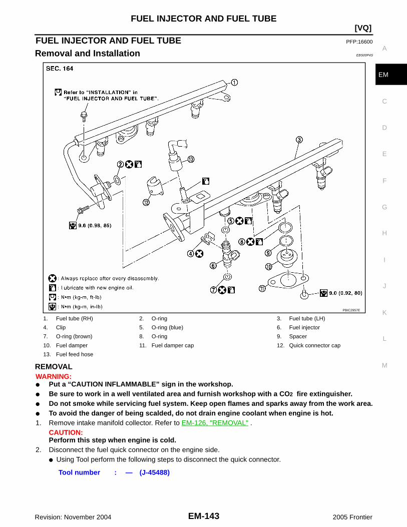
FUEL INJECTOR AND FUEL TUBE
EM-143
[VQ]
C
D
E
F
G
H
I
J
K
L
M
A
EM
Revision: November 2004 2005 Frontier
FUEL INJECTOR AND FUEL TUBE PFP:16600
Removal and Installation EBS00P4S
REMOVALWARNING:● Put a “CAUTION INFLAMMABLE” sign in the workshop.● Be sure to work in a well ventilated area and furnish workshop with a CO2 fire extinguisher.● Do not smoke while servicing fuel system. Keep open flames and sparks away from the work area.● To avoid the danger of being scalded, do not drain engine coolant when engine is hot.1. Remove intake manifold collector. Refer to EM-126, "REMOVAL" .
CAUTION:Perform this step when engine is cold.
2. Disconnect the fuel quick connector on the engine side.● Using Tool perform the following steps to disconnect the quick connector.
1. Fuel tube (RH) 2. O-ring 3. Fuel tube (LH)
4. Clip 5. O-ring (blue) 6. Fuel injector
7. O-ring (brown) 8. O-ring 9. Spacer
10. Fuel damper 11. Fuel damper cap 12. Quick connector cap
13. Fuel feed hose
PBIC2957E
Tool number : — (J-45488)
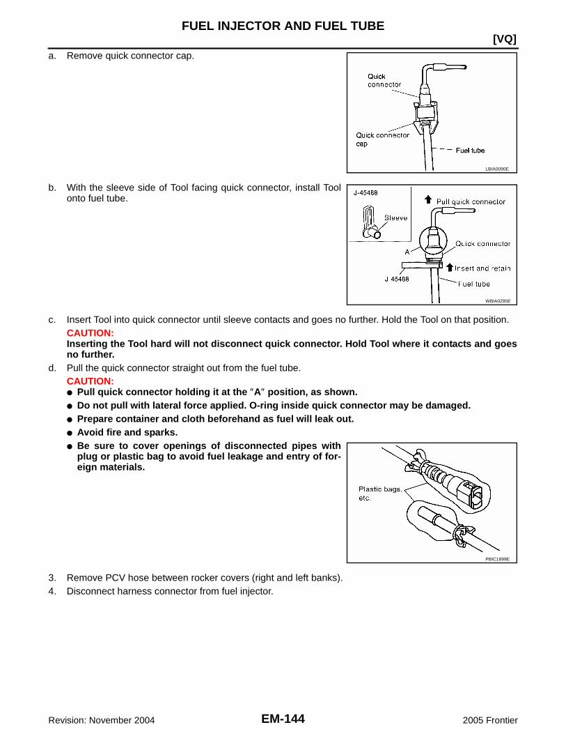
EM-144Revision: November 2004
[VQ]FUEL INJECTOR AND FUEL TUBE
2005 Frontier
a. Remove quick connector cap.
b. With the sleeve side of Tool facing quick connector, install Toolonto fuel tube.
c. Insert Tool into quick connector until sleeve contacts and goes no further. Hold the Tool on that position.CAUTION:Inserting the Tool hard will not disconnect quick connector. Hold Tool where it contacts and goesno further.
d. Pull the quick connector straight out from the fuel tube.CAUTION:● Pull quick connector holding it at the ″A″ position, as shown.● Do not pull with lateral force applied. O-ring inside quick connector may be damaged.● Prepare container and cloth beforehand as fuel will leak out.● Avoid fire and sparks.● Be sure to cover openings of disconnected pipes with
plug or plastic bag to avoid fuel leakage and entry of for-eign materials.
3. Remove PCV hose between rocker covers (right and left banks).4. Disconnect harness connector from fuel injector.
LBIA0090E
WBIA0295E
PBIC1899E

FUEL INJECTOR AND FUEL TUBE
EM-145
[VQ]
C
D
E
F
G
H
I
J
K
L
M
A
EM
Revision: November 2004 2005 Frontier
5. Loosen bolts in reverse order as shown, and remove fuel tubeand fuel injector assembly.CAUTION:Do not tilt it, or remaining fuel in pipes may flow out frompipes.
6. Remove bolts which connects fuel tube (RH) and fuel tube (LH).7. Remove fuel injector from fuel tube as follows:a. Carefully open and remove clip.b. Remove fuel injector from fuel tube by pulling straight.
CAUTION:● Be careful with remaining fuel that may go out from fuel
tube.● Be careful not to damage injector nozzles during
removal.● Do not bump or drop fuel injector.● Do not disassemble fuel injector.
8. Disconnect fuel tube (RH) from fuel tube (LH).9. Loosen bolts, to remove fuel damper cap and fuel damper, if necessary.
PBIC2902E
PBIC2999E

EM-146Revision: November 2004
[VQ]FUEL INJECTOR AND FUEL TUBE
2005 Frontier
INSTALLATION1. Install fuel damper as follows:a. Install new O-ring to fuel tube as shown.
● When handling new O-rings, be careful of the following cau-tion:CAUTION:● Handle O-ring with bare hands. Do not wear gloves.● Lubricate O-ring with new engine oil.● Do not clean O-ring with solvent.● Make sure that O-ring and its mating part are free of
foreign material.● When installing O-ring, be careful not to scratch it with
tool or fingernails. Also be careful not to twist orstretch O-ring. If O-ring was stretched while it wasbeing attached, do not insert it quickly into fuel tube.
● Insert new O-ring straight into fuel tube. Do not twist it.b. Install spacer to fuel damper.c. Insert fuel damper straight into fuel tube.
CAUTION:● Insert straight, making sure that the axis is lined up.● Do not pressure-fit with excessive force.
● Insert fuel damper until “B” is touching “A” of fuel tube.d. Tighten bolts evenly in turn.
● After tightening bolts, make sure that there is no gap between fuel damper cap and fuel tube.2. Install new O-rings to fuel injector, paying attention to the following.
CAUTION:● Upper and lower O-ring are different. Be careful not to confuse them.
● Handle O-ring with bare hands. Do not wear gloves.● Lubricate O-ring with new engine oil.● Do not clean O-ring with solvent.● Make sure that O-ring and its mating part are free of foreign material.● When installing O-ring, be careful not to scratch it with tool or fingernails. Also be careful not to
twist or stretch O-ring. If O-ring was stretched while it was being attached, do not insert itquickly into fuel tube.
● Insert O-ring straight into fuel injector. Do not twist it.
Reference value : 130 N (13.3 kg, 29.2 lb)
Fuel tube side : BlueNozzle side : Brown
PBIC2903E

FUEL INJECTOR AND FUEL TUBE
EM-147
[VQ]
C
D
E
F
G
H
I
J
K
L
M
A
EM
Revision: November 2004 2005 Frontier
3. Install fuel injector to fuel tube as follows:a. Insert clip into clip mounting groove on fuel injector.
● Insert clip so that protrusion “A” of fuel injector matches cutout“A” of clip.CAUTION:● Do not reuse clip. Replace it with a new one.● Be careful to keep clip from interfering with O-ring. If
interference occurs, replace O-ring.b. Insert fuel injector into fuel tube with clip attached.
● Insert it while matching it to the axial center.● Insert fuel injector so that protrusion “B” of fuel tube matches
cutout “B” of clip.● Make sure that fuel tube flange is securely fixed in flange fix-
ing groove on clip.c. Make sure that installation is complete by checking that fuel
injector does not rotate or come off.● Make sure that protrusions of fuel injectors are aligned with
cutouts of clips after installation.
4. Connect fuel tube (RH) to fuel tube (LH), and tighten bolts temporarily.● Tighten bolts with the specified torque after installing fuel tube and fuel injector assembly.CAUTION:● Handle O-ring with bare hands. Do not wear gloves.● Lubricate O-ring with new engine oil.● Do not clean O-ring with solvent.● Make sure that O-ring and its mating part are free of foreign material.● When installing O-ring, be careful not to scratch it with tool or fingernails. Also be careful not to
twist or stretch O-ring. If O-ring was stretched while it was being attached, do not insert itquickly into fuel tube.
● Insert new O-ring straight into fuel tube. Do not twist it.5. Install fuel tube and fuel injector assembly to intake manifold.
CAUTION:Be careful not to let tip of injector nozzle come in contact with other parts.● Tighten bolts in two steps in numerical order as shown.
6. Tighten bolts which connects fuel tube (RH) and fuel tube (LH) with the specified torque.7. Connect fuel injector harness connector.8. Install intake manifold collector. Refer to EM-127, "INSTALLATION" .9. Installation of the remaining components is in the reverse order of removal.
PBIC3000E
Fuel injector tube assembly bolts1st step : 10.1 N·m (1.0 kg-m, 7 ft-lb)2nd step : 22.0 N·m (2.2 kg-m, 16 ft-lb)
PBIC2902E

EM-148Revision: November 2004
[VQ]FUEL INJECTOR AND FUEL TUBE
2005 Frontier
INSPECTION AFTER INSTALLATIONCheck on Fuel Leakage1. Turn ignition switch “ON” (with engine stopped). With fuel pressure applied to fuel piping, check for fuel
leakage at connection points.NOTE:Use mirrors for checking at points out of clear sight.
2. Start engine. With engine speed increased, check again for fuel leakage at connection points.CAUTION:Do not touch engine immediately after stopped, as engine becomes extremely hot.

ROCKER COVER
EM-149
[VQ]
C
D
E
F
G
H
I
J
K
L
M
A
EM
Revision: November 2004 2005 Frontier
ROCKER COVER PFP:13264
Removal and Installation EBS00P4T
REMOVAL (LEFT BANK)1. Remove engine cover. Refer to EM-121, "REMOVAL" .2. Separate engine harness removing their brackets from rocker covers.3. Remove harness bracket from cylinder head, if necessary.4. Remove ignition coil. Refer to EM-140, "Removal and Installation" .5. Remove PCV hoses from rocker covers.6. Remove oil filler cap from rocker cover (left bank), if necessary.
1. Oil filler cap 2. PCV hose 3. PCV valve
4. O-ring 5. Rocker cover (right bank) 6. PCV hose
7. Rocker cover gasket (right bank) 8. Rocker cover gasket (left bank) 9. Rocker cover (left bank)
10. PCV hose
PBIC2905E
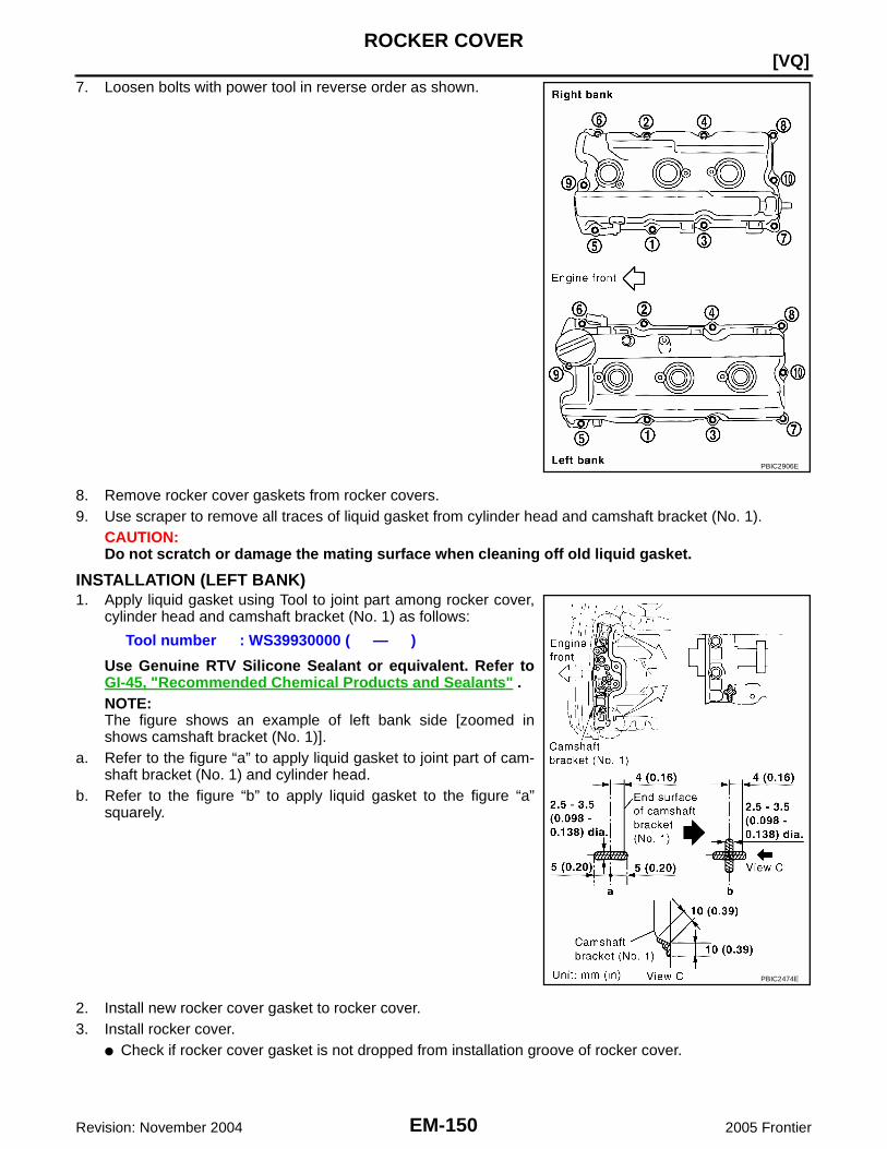
EM-150Revision: November 2004
[VQ]ROCKER COVER
2005 Frontier
7. Loosen bolts with power tool in reverse order as shown.
8. Remove rocker cover gaskets from rocker covers.9. Use scraper to remove all traces of liquid gasket from cylinder head and camshaft bracket (No. 1).
CAUTION:Do not scratch or damage the mating surface when cleaning off old liquid gasket.
INSTALLATION (LEFT BANK)1. Apply liquid gasket using Tool to joint part among rocker cover,
cylinder head and camshaft bracket (No. 1) as follows:
Use Genuine RTV Silicone Sealant or equivalent. Refer toGI-45, "Recommended Chemical Products and Sealants" .NOTE:The figure shows an example of left bank side [zoomed inshows camshaft bracket (No. 1)].
a. Refer to the figure “a” to apply liquid gasket to joint part of cam-shaft bracket (No. 1) and cylinder head.
b. Refer to the figure “b” to apply liquid gasket to the figure “a”squarely.
2. Install new rocker cover gasket to rocker cover.3. Install rocker cover.
● Check if rocker cover gasket is not dropped from installation groove of rocker cover.
PBIC2906E
Tool number : WS39930000 ( — )
PBIC2474E

ROCKER COVER
EM-151
[VQ]
C
D
E
F
G
H
I
J
K
L
M
A
EM
Revision: November 2004 2005 Frontier
4. Tighten bolts in two steps separately in numerical order asshown.
5. Install oil filer cap to rocker cover (left bank), if removed.6. Install PCV hose.
● Insert PCV hose by 25 to 30 mm (0.98 to 1.18 in) from connector end.● When installing, be careful not to twist or come in contact with other parts.
7. Installation of the remaining components is in the reverse order of removal.
REMOVAL (RIGHT BANK)1. Remove intake manifold collector. Refer to EM-126, "REMOVAL" .
CAUTION:Perform this step when engine is cold.
2. Separate engine harness removing their brackets from rocker covers.3. Remove harness bracket from cylinder head (right bank). Refer to EM-200, "CYLINDER HEAD" .4. Remove ignition coil. Refer to EM-140, "Removal and Installation" .5. Remove PCV hoses from rocker cover.6. Remove PCV valve and O-ring from rocker cover (right bank), if necessary.
1st step : 1.96 N·m (0.20 kg-m, 17 in-lb)2nd step : 8.33 N·m (0.85 kg-m, 74 in-lb)
PBIC2906E

EM-152Revision: November 2004
[VQ]ROCKER COVER
2005 Frontier
7. Loosen bolts with power tool in reverse order as shown.
8. Remove rocker cover gaskets from rocker covers.9. Use scraper to remove all traces of liquid gasket from cylinder head and camshaft bracket (No. 1).
CAUTION:Do not scratch or damage the mating surface when cleaning off old liquid gasket.
INSTALLATION (RIGHT BANK)1. Apply liquid gasket using Tool to joint part among rocker cover,
cylinder head and camshaft bracket (No. 1) as follows:
Use Genuine RTV Silicone Sealant or equivalent. Refer toGI-45, "Recommended Chemical Products and Sealants" .NOTE:The figure shows an example of left bank side [zoomed inshows camshaft bracket (No. 1)].
a. Refer to the figure “a” to apply liquid gasket to joint part of cam-shaft bracket (No. 1) and cylinder head.
b. Refer to the figure “b” to apply liquid gasket to the figure “a”squarely.
2. Install new rocker cover gasket to rocker cover.3. Install rocker cover.
● Check if rocker cover gasket is not dropped from installation groove of rocker cover.
PBIC2906E
Tool number : WS39930000 ( — )
PBIC2474E

ROCKER COVER
EM-153
[VQ]
C
D
E
F
G
H
I
J
K
L
M
A
EM
Revision: November 2004 2005 Frontier
4. Tighten bolts in two steps separately in numerical order asshown.
5. Install new O-ring and PCV valve to rocker cover (right bank), if removed.6. Install PCV hose.
● Insert PCV hose by 25 to 30 mm (0.98 to 1.18 in) from connector end.● When installing, be careful not to twist or come in contact with other parts.
7. Installation of the remaining components is in the reverse order of removal.
1st step : 1.96 N·m (0.20 kg-m, 17 in-lb)2nd step : 8.33 N·m (0.85 kg-m, 74 in-lb)
PBIC2906E

EM-154Revision: November 2004
[VQ]FRONT TIMING CHAIN CASE
2005 Frontier
FRONT TIMING CHAIN CASE PFP:13599
Removal and Installation EBS00P4U
NOTE:● This section describes removal/installation procedure of front timing chain case and timing chain related
parts without removing oil pan (upper) on vehicle.● When oil pan (upper) needs to be removed or installed, or when rear timing chain case is removed or
installed, remove oil pans (upper and lower) first. Then remove front timing chain case, timing chainrelated parts, and rear timing chain case in this order, and installation is in the reverse order of removal.Refer to EM-163, "TIMING CHAIN" .
● Refer to EM-163, "TIMING CHAIN" for component parts location.
REMOVAL1. Remove engine cover with power tool. Refer to EM-121, "REMOVAL" .2. Release the fuel pressure. Refer to EC-708, "FUEL PRESSURE RELEASE" .3. Drain engine oil. Refer to LU-20, "Changing Engine Oil" .
CAUTION:● Perform this step when engine is cold.● Do not spill engine oil on drive belts.
4. Drain engine coolant from radiator. Refer to MA-21, "Changing Engine Coolant" .CAUTION:● Perform this step when engine is cold.● Do not spill engine coolant on drive belts.
5. Remove radiator cooling fan assembly. Refer to CO-36, "ENGINE COOLING FAN" .6. Separate engine harnesses removing their brackets from front timing chain case.7. Remove drive belts. Refer to EM-122, "Removal" .8. Remove power steering oil pump from bracket with piping connected, and temporarily secure it aside.
Refer to PS-21, "REMOVAL" .9. Remove power steering oil pump bracket. Refer to PS-21, "REMOVAL" .10. Remove alternator. Refer to SC-38, "REMOVAL" .11. Remove water bypass hose, water hose clamp and idler pulley bracket from front timing chain case.12. Remove right and left intake valve timing control covers.
● Loosen bolts in reverse order as shown.● Cut liquid gasket for removal using Tool.
CAUTION:Shaft is internally jointed with camshaft sprocket (INT) cen-ter hole. When removing, keep it horizontal until it is com-pletely disconnected.
13. Remove collared O-rings from front timing chain case (left andright side).
Tool number : KV10111100 (J-37228)
SEM728G
PBIC2631E

FRONT TIMING CHAIN CASE
EM-155
[VQ]
C
D
E
F
G
H
I
J
K
L
M
A
EM
Revision: November 2004 2005 Frontier
14. Remove rocker covers (right and left banks). Refer to EM-149, "Removal and Installation" .NOTE:When only timing chain (primary) is removed, rocker cover does not need to be removed.
15. Obtain No. 1 cylinder at TDC of its compression stroke as follows:NOTE:When timing chain is not removed/installed, this step is not required.
a. Rotate crankshaft pulley clockwise to align timing mark (groovedline without color) with timing indicator.
b. Make sure that intake and exhaust cam noses on No. 1 cylinder(engine front side of right bank) are located as shown.● If not, turn crankshaft one revolution (360°) and align as
shown.NOTE:When only timing chain (primary) is removed, rocker cover doesnot need to be removed. To make sure that No. 1 cylinder is atits compression TDC, remove front timing chain case first. Thencheck mating marks on camshaft sprockets. Refer to EM-172,"INSTALLATION" .
16. Remove crankshaft pulley as follows:a. Remove starter motor and set Tool. Refer to SC-23,
"REMOVAL" .
b. Loosen crankshaft pulley bolt and locate bolt seating surface as10 mm (0.39 in) from its original position.CAUTION:Do not remove crankshaft pulley bolt. Keep loosenedcrankshaft pulley bolt in place to protect the crankshaft pul-ley from dropping.
c. Pull crankshaft pulley with both hands to remove it.
KBIA1717J
SEM418G
Tool number : KV10117700 (J-44716)
WBIA0580E
PBIC2918E

EM-156Revision: November 2004
[VQ]FRONT TIMING CHAIN CASE
2005 Frontier
17. Loosen two bolts in front of oil pan (upper) in reverse order asshown.
18. Remove front timing chain case as follows:a. Loosen bolts with power tool in reverse order as shown.
b. Insert suitable tool into the notch at the top of the front timingchain case as shown (1).
c. Pry off case by moving tool as shown (2).● Cut liquid gasket for removal using Tool.
CAUTION:● Do not use screwdriver or something similar.● After removal, handle front timing chain case carefully so
it does not tilt, cant, or warp under a load.
19. Remove O-rings from rear timing chain case.
20. Remove water pump cover and chain tensioner cover from front timing chain case, if necessary.● Cut liquid gasket for removal using Tool.
PBIC2907E
PBIC2908E
Tool number : KV10111100 (J-37228)
SEM156F
PBIC2548E

FRONT TIMING CHAIN CASE
EM-157
[VQ]
C
D
E
F
G
H
I
J
K
L
M
A
EM
Revision: November 2004 2005 Frontier
21. Remove front oil seal from front timing chain case using suitabletool.CAUTION:Be careful not to damage front timing chain case.
22. Remove timing chain and related parts. Refer to EM-164, "REMOVAL" .23. Use a scraper to remove all traces of old liquid gasket from front
and rear timing chain cases and oil pan (upper), and liquid gas-ket mating surfaces.CAUTION:Be careful not to allow gasket fragments to enter oil pan.
● Remove old liquid gasket from bolt hole and thread.
24. Use a scraper to remove all traces of old liquid gasket fromwater pump cover, chain tensioner cover and intake valve timingcontrol covers.
PBIC2909E
PBIC2910E
PBIC2084E
SEM926E
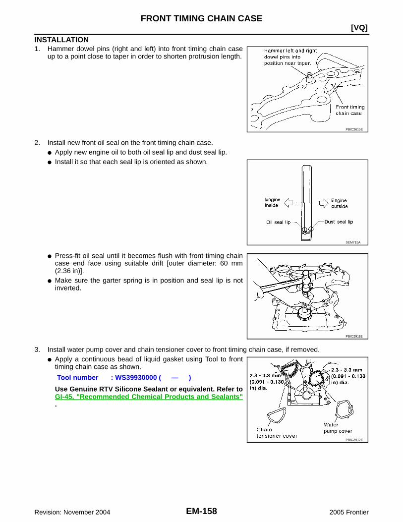
EM-158Revision: November 2004
[VQ]FRONT TIMING CHAIN CASE
2005 Frontier
INSTALLATION1. Hammer dowel pins (right and left) into front timing chain case
up to a point close to taper in order to shorten protrusion length.
2. Install new front oil seal on the front timing chain case.● Apply new engine oil to both oil seal lip and dust seal lip.● Install it so that each seal lip is oriented as shown.
● Press-fit oil seal until it becomes flush with front timing chaincase end face using suitable drift [outer diameter: 60 mm(2.36 in)].
● Make sure the garter spring is in position and seal lip is notinverted.
3. Install water pump cover and chain tensioner cover to front timing chain case, if removed.● Apply a continuous bead of liquid gasket using Tool to front
timing chain case as shown.
Use Genuine RTV Silicone Sealant or equivalent. Refer toGI-45, "Recommended Chemical Products and Sealants".
PBIC2615E
SEM715A
PBIC2911E
Tool number : WS39930000 ( — )
PBIC2912E

FRONT TIMING CHAIN CASE
EM-159
[VQ]
C
D
E
F
G
H
I
J
K
L
M
A
EM
Revision: November 2004 2005 Frontier
4. Install front timing chain case as follows:a. Apply a continuous bead of liquid gasket using Tool to front timing chain case back side as shown.
Use Genuine RTV Silicone Sealant or equivalent. Refer toGI-45, "Recommended Chemical Products and Sealants" .
b. Install new O-rings on rear timing chain case.c. Assemble front timing chain case as follows:
i.
Fit lower end of front timing chain case tightly onto top face of oilpan (upper). From the fitting point, make entire front timing chaincase contact rear timing chain case completely.
PBIC2913E
PBIC2548E
PBIC1100E

EM-160Revision: November 2004
[VQ]FRONT TIMING CHAIN CASE
2005 Frontier
ii. Since front timing chain case is offset for difference of bolt holes,tighten bolts temporarily while holding front timing chain casefrom front and top as shown.
iii. Same as the previous step, insert dowel pin while holding fronttiming chain case from front and top completely.
d. Tighten bolts to the specified torque in numerical order asshown.● There are four type of bolts. Refer to the following for locating
bolts.
e. After all bolts tightened, retighten them to the specified torque in numerical order as shown.5. Install two bolts in front of oil pan (upper) in numerical order as
shown.
6. Install right and left intake valve timing control covers as follows:a. Install new seal rings in shaft grooves.b. Apply a continuous bead of liquid gasket using Tool to intake
valve timing control covers as shown.
Use Genuine RTV Silicone Sealant or equivalent. Refer toGI-45, "Recommended Chemical Products and Sealants" .
PBIC2915E
Bolt position Bolt diameter1 - 5 : 10 mm (0.39 in)6 – 25 : 6 mm (0.24 in)
Bolt position Tightening specification1 - 5 : 55.0 N·m (5.6 kg-m, 41 ft-lb)6 – 25 : 12.7 N·m (1.3 kg-m, 9 ft-lb)
Front oil pan bolt torque : 22.0 N·m (2.2 kg-m, 16 ft-lb)
PBIC2908E
PBIC2907E
Tool number : WS39930000 ( — )
SBIA0492E

FRONT TIMING CHAIN CASE
EM-161
[VQ]
C
D
E
F
G
H
I
J
K
L
M
A
EM
Revision: November 2004 2005 Frontier
c. Install new collared O-rings in front timing chain case oil hole(left and right sides).
d. Being careful not to move seal ring from the installation groove, align dowel pins on front timing chaincase with the holes to install intake valve timing control covers.
e. Tighten bolts in numerical order as shown.
7. Install crankshaft pulley as follows:a. Install crankshaft pulley, taking care not to damage front oil seal.
● When press-fitting crankshaft pulley with plastic hammer, tap on its center portion (not circumference).b. Tighten crankshaft pulley bolt.
c. Put a paint mark on crankshaft pulley aligning with angle markon crankshaft pulley bolt. Then, further retighten bolt by 60degrees (equivalent to one graduation).
8. Rotate crankshaft pulley in normal direction (clockwise when viewed from front) to confirm it turnssmoothly.
9. Installation of the remaining components is in the reverse order of removal after this step.
INSPECTION AFTER INSTALLATIONInspection for LeaksThe following are procedures for checking fluid leaks, lubricant leaks and exhaust gases leaks.● Before starting engine, check oil/fluid levels including engine coolant and engine oil. If less than required
quantity, fill to the specified level. Refer to MA-11, "RECOMMENDED FLUIDS AND LUBRICANTS" .● Use procedure below to check for fuel leakage.● Turn ignition switch “ON” (with engine stopped). With fuel pressure applied to fuel piping, check for fuel
leakage at connection points.● Start engine. With engine speed increased, check again for fuel leakage at connection points.
PBIC2631E
PBIC0918E
Crankshaft bolt torque : 44.1 N·m (4.5 kg-m, 33 ft-lb)
PBIC2916E

EM-162Revision: November 2004
[VQ]FRONT TIMING CHAIN CASE
2005 Frontier
● Run engine to check for unusual noise and vibration.NOTE:If hydraulic pressure inside timing chain tensioner drops after removal/installation, slack in the guide maygenerate a pounding noise during and just after engine start. However, this is normal. Noise will stop afterhydraulic pressure rises.
● Warm up engine thoroughly to make sure there is no leakage of fuel, exhaust gases, or any oil/fluidsincluding engine oil and engine coolant.
● Bleed air from lines and hoses of applicable lines, such as in cooling system.● After cooling down engine, again check oil/fluid levels including engine oil and engine coolant. Refill to the
specified level, if necessary.
Summary of the inspection items:
* Transmission/transaxle/CVT fluid, power steering fluid, brake fluid, etc.
Item Before starting engine Engine running After engine stopped
Engine coolant Level Leakage Level
Engine oil Level Leakage Level
Other oils and fluid* Level Leakage Level
Fuel Leakage Leakage Leakage

TIMING CHAIN
EM-163
[VQ]
C
D
E
F
G
H
I
J
K
L
M
A
EM
Revision: November 2004 2005 Frontier
TIMING CHAIN PFP:13028
Removal and Installation EBS00P4V
PBIC2917E

EM-164Revision: November 2004
[VQ]TIMING CHAIN
2005 Frontier
NOTE:● This section describes procedures for removing/installing front timing chain case and timing chain related
parts, and rear timing chain case, when oil pan (upper) needs to be removed/installed for engine overhaul,etc.
● To remove/install front timing chain case, timing chain, and its related parts without removing oil pan(upper), refer to EM-154, "FRONT TIMING CHAIN CASE" .
REMOVAL1. Remove engine cover with power tool. Refer to EM-121, "REMOVAL" .2. Release the fuel pressure. Refer to EC-708, "FUEL PRESSURE RELEASE" .3. Drain engine oil. Refer to LU-20, "Changing Engine Oil" .
CAUTION:● Perform this step when engine is cold.● Do not spill engine oil on drive belts.
4. Drain engine coolant from radiator. Refer to MA-21, "Changing Engine Coolant" .CAUTION:● Perform this step when engine is cold.● Do not spill engine coolant on drive belts.
5. Remove radiator cooling fan assembly. Refer to CO-36, "ENGINE COOLING FAN" .6. Separate engine harnesses removing their brackets from front timing chain case.7. Remove drive belts. Refer to EM-122, "Removal" .8. Remove power steering oil pump from bracket with piping connected, and temporarily secure it aside.
Refer to PS-21, "REMOVAL" .9. Remove power steering oil pump bracket. Refer to PS-21, "REMOVAL" .10. Remove alternator. Refer to SC-38, "REMOVAL" .11. Remove water bypass hose, water hose clamp and idler pulley bracket from front timing chain case.12. Remove right and left intake valve timing control covers.
● Loosen bolts in reverse order as shown.● Cut liquid gasket for removal using Tool.
CAUTION:Shaft is internally jointed with camshaft sprocket (INT) cen-ter hole. When removing, keep it horizontal until it is com-pletely disconnected.
1.Timing chain tensioner (secondary)(left bank)
2. Internal chain guide 3.Timing chain tensioner (secondary)(right bank)
4. Camshaft sprocket (EXH) 5. Timing chain (secondary) 6. Timing chain (primary)
7. Camshaft sprocket (INT) 8. Camshaft sprocket (INT) 9. Slack guide
10. Timing chain tensioner (primary) 11. Crankshaft sprocket 12. Collared O-ring
13. O-ring 14. Intake valve timing control cover 15. Idler pulley
16. Drive belt auto tensioner 17. Cooling fan bracket 18. Crankshaft pulley
19. Front oil seal 20. Water pump cover 21. Chain tensioner cover
22. Front timing chain case 23. Rear timing chain case 24. Water drain plug (front)
25. Tension guide 26. O-ring
Tool number : KV10111100 (J-37228)
SEM728G
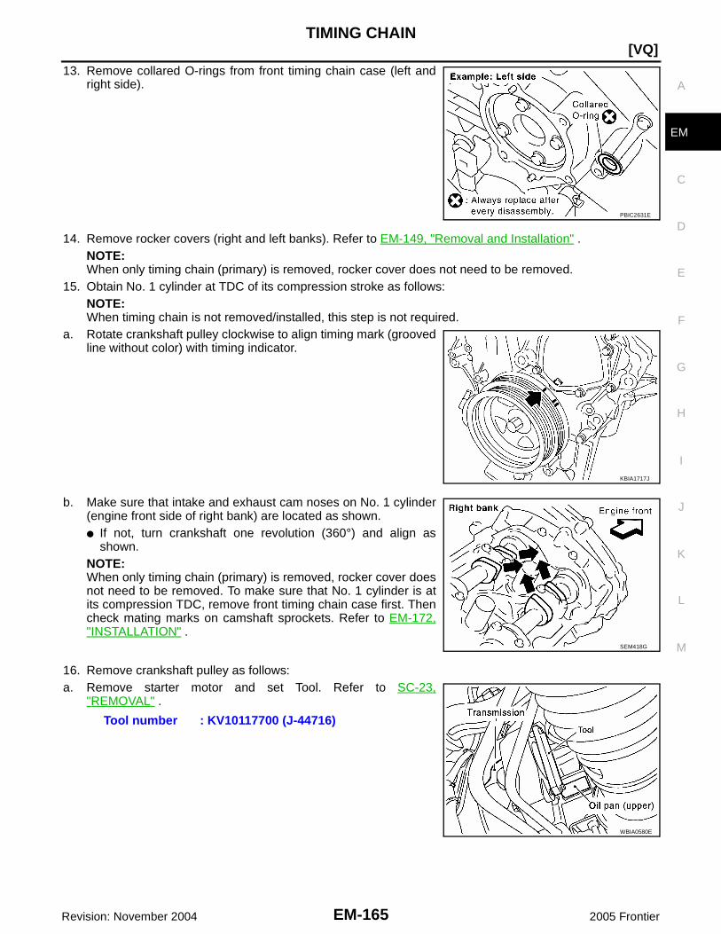
TIMING CHAIN
EM-165
[VQ]
C
D
E
F
G
H
I
J
K
L
M
A
EM
Revision: November 2004 2005 Frontier
13. Remove collared O-rings from front timing chain case (left andright side).
14. Remove rocker covers (right and left banks). Refer to EM-149, "Removal and Installation" .NOTE:When only timing chain (primary) is removed, rocker cover does not need to be removed.
15. Obtain No. 1 cylinder at TDC of its compression stroke as follows:NOTE:When timing chain is not removed/installed, this step is not required.
a. Rotate crankshaft pulley clockwise to align timing mark (groovedline without color) with timing indicator.
b. Make sure that intake and exhaust cam noses on No. 1 cylinder(engine front side of right bank) are located as shown.● If not, turn crankshaft one revolution (360°) and align as
shown.NOTE:When only timing chain (primary) is removed, rocker cover doesnot need to be removed. To make sure that No. 1 cylinder is atits compression TDC, remove front timing chain case first. Thencheck mating marks on camshaft sprockets. Refer to EM-172,"INSTALLATION" .
16. Remove crankshaft pulley as follows:a. Remove starter motor and set Tool. Refer to SC-23,
"REMOVAL" .
PBIC2631E
KBIA1717J
SEM418G
Tool number : KV10117700 (J-44716)
WBIA0580E

EM-166Revision: November 2004
[VQ]TIMING CHAIN
2005 Frontier
b. Loosen crankshaft pulley bolt and locate bolt seating surface as10 mm (0.39 in) from its original position.CAUTION:Do not remove crankshaft pulley bolt. Keep loosenedcrankshaft pulley bolt in place protect removed crankshaftpulley from dropping.
c. Pull crankshaft pulley with both hands to remove it.17. Loosen two bolts in front of oil pan (upper) in reverse order as
shown.
18. Remove front timing chain case as follows:a. Loosen bolts with power tool in reverse order as shown.
b. Insert suitable tool into the notch at the top of the front timingchain case as shown (1).
c. Pry off case by moving tool as shown (2).● Cut liquid gasket for removal using Tool.
CAUTION:● Do not use screwdriver or something similar.● After removal, handle front timing chain case carefully so
it does not tilt, cant, or warp under a load.
PBIC2918E
PBIC2907E
PBIC2908E
Tool number : KV10111100 (J-37228)
SEM156F
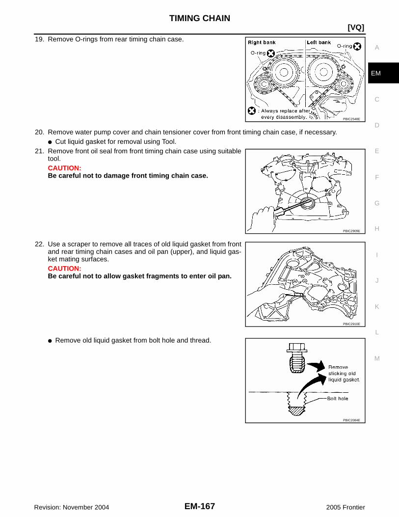
TIMING CHAIN
EM-167
[VQ]
C
D
E
F
G
H
I
J
K
L
M
A
EM
Revision: November 2004 2005 Frontier
19. Remove O-rings from rear timing chain case.
20. Remove water pump cover and chain tensioner cover from front timing chain case, if necessary.● Cut liquid gasket for removal using Tool.
21. Remove front oil seal from front timing chain case using suitabletool.CAUTION:Be careful not to damage front timing chain case.
22. Use a scraper to remove all traces of old liquid gasket from frontand rear timing chain cases and oil pan (upper), and liquid gas-ket mating surfaces.CAUTION:Be careful not to allow gasket fragments to enter oil pan.
● Remove old liquid gasket from bolt hole and thread.
PBIC2548E
PBIC2909E
PBIC2910E
PBIC2084E

EM-168Revision: November 2004
[VQ]TIMING CHAIN
2005 Frontier
23. Use a scraper to remove all traces of old liquid gasket fromwater pump cover, chain tensioner cover and intake valve timingcontrol covers.
24. Remove timing chain tensioner (primary) as follows:a. Loosen clip of timing chain tensioner (primary), and release
plunger stopper. (1)b. Insert plunger into tensioner body by pressing slack guide. (2)c. Keep slack guide pressed and hold plunger in by pushing stop-
per pin through the tensioner body hole and plunger groove. (3)
d. Remove bolts and remove timing chain tensioner (primary).25. Remove internal chain guide, tension guide and slack guide.
NOTE:Tension guide can be removed after removing timing chain (pri-mary).
26. Remove timing chain (primary) and crankshaft sprocket.CAUTION:After removing timing chain (primary), do not turn crankshaft and camshaft separately, or valveswill strike the piston heads.
27. Remove timing chain (secondary) and camshaft sprockets as follows:
SEM926E
PBIC2919E
PBIC2266E

TIMING CHAIN
EM-169
[VQ]
C
D
E
F
G
H
I
J
K
L
M
A
EM
Revision: November 2004 2005 Frontier
a. Attach suitable stopper pin to the right and left timing chain ten-sioners (secondary).NOTE:● Use approximately 0.5 mm (0.02 in) dia. hard metal pin as a
stopper pin.● For removal of timing chain tensioner (secondary), refer to
EM-183, "CAMSHAFT" . [Removing camshaft bracket (No. 1)is required.]
b. Remove camshaft sprocket (INT and EXH) bolts.● Secure the hexagonal portion of camshaft using wrench to
loosen bolts.CAUTION:Do not loosen bolts with securing anything other than thecamshaft hexagonal portion or with tensioning the timingchain.
c. Remove timing chain (secondary) together with camshaft sprockets.● Turn camshaft slightly to secure slackness of timing chain on timing chain tensioner (secondary) side.● Insert 0.5 mm (0.020 in)-thick metal or resin plate between
timing chain and timing chain tensioner plunger (guide).Remove timing chain (secondary) together with camshaftsprockets with timing chain loose from guide groove.CAUTION:Be careful of plunger coming off when removing timingchain (secondary). This is because plunger of timingchain tensioner (secondary) moves during operation,leading to coming off of fixed stopper pin.NOTE:Camshaft sprocket (INT) is a one piece integrated designsprockets for timing chain (primary) and for timing chain (sec-ondary).
● When handling camshaft sprocket (INT), be careful of the fol-lowing:CAUTION:● Handle carefully to avoid any shock to camshaft
sprocket.● Do not disassemble. (Do not loosen bolts “A” as
shown).
28. Remove water pump. Refer to CO-38, "REMOVAL" .
PBIC2047E
KBIA1698J
PBIC1978E
PBIC2920E

EM-170Revision: November 2004
[VQ]TIMING CHAIN
2005 Frontier
29. Remove rear timing chain case as follows:
a. Loosen and remove bolts with power tool in reverse order asshown.
b. Cut liquid gasket using Tool and remove rear timing chain case.
CAUTION:● Do not remove plate metal cover of oil passage.● After removal, handle rear timing chain case carefully so
it does not tilt, cant, or warp under a load.
30. Remove O-rings from cylinder head and camshaft bracket(No. 1).
31. Remove O-rings from cylinder block.
32. Remove timing chain tensioners (secondary) from cylinder head if necessary.a. Remove camshaft brackets (No. 1). Refer to EM-184, "REMOVAL" .b. Remove timing chain tensioners (secondary) with stopper pin attached.
Tool number : KV10111100 (J-37228)
PBIC2921E
PBIC2922E
SBIA0496E
PBIC0788E

TIMING CHAIN
EM-171
[VQ]
C
D
E
F
G
H
I
J
K
L
M
A
EM
Revision: November 2004 2005 Frontier
33. Use scraper to remove all traces of old liquid gasket from frontand rear timing chain cases, and opposite mating surfaces.
● Remove old liquid gasket from bolt hole and thread.
34. Use scraper to remove all traces of liquid gasket from waterpump cover, chain tensioner cover and intake valve timing con-trol covers.
INSPECTION AFTER REMOVALTiming ChainCheck for cracks and any excessive wear at link plates and rollerlinks of timing chain. Replace timing chain as necessary.
PBIC2910E
PBIC2084E
SEM926E
PBIC0282E

EM-172Revision: November 2004
[VQ]TIMING CHAIN
2005 Frontier
INSTALLATIONNOTE:The figure below shows the relationship between the mating mark on each timing chain and that on the corre-sponding sprocket, with the components installed.
1. Install timing chain tensioners (secondary) to cylinder head if removed. Refer to EM-172, "INSTALLA-TION" .
a. Install timing chain tensioners (secondary) with stopper pin attached and new O-ring.b. Install camshaft brackets (No. 1). Refer to EM-188, "INSTALLATION" .2. Install rear timing chain case as follows:a. Install new O-rings onto cylinder block.
PBIC2923E
PBIC0788E

TIMING CHAIN
EM-173
[VQ]
C
D
E
F
G
H
I
J
K
L
M
A
EM
Revision: November 2004 2005 Frontier
b. Install new O-rings to cylinder head and camshaft bracket(No. 1).
c. Apply liquid gasket using Tool to rear timing chain case back side as shown.
Use Genuine RTV Silicone Sealant or equivalent. Refer to GI-45, "Recommended Chemical Prod-ucts and Sealants" .CAUTION:● For “A” in the figure, completely wipe out liquid gasket extended on a portion touching at
engine coolant.● Apply liquid gasket on installation position of water pump and cylinder head very completely.
d. Align rear timing chain case with dowel pins (right and left) on cylinder block and install rear timing chaincase.● Make sure O-rings stay in place during installation to cylinder block, cylinder head and camshaft
bracket (No. 1).
SBIA0496E
Tool number : WS39930000 ( — )
PBIC2924E

EM-174Revision: November 2004
[VQ]TIMING CHAIN
2005 Frontier
e. Tighten bolts in numerical order as shown.● There are two type of bolts. Refer to the following for locating
bolts.
f. After all bolts are tightened, retighten them to the specifiedtorque in numerical order as shown.● If liquid gasket protrudes, wipe it off immediately.
g. After installing rear timing chain case, check the surface heightdifference between following parts on oil pan (upper) mountingsurface.
● If not within the standard, repeat the installation procedure.
3. Install water pump with new O-rings. Refer to CO-40, "INSTALLATION" .4. Make sure that dowel pin hole, dowel pin of camshaft and crank-
shaft key are located as shown. (No. 1 cylinder at compressionTDC)● NOTE:
Though camshaft does not stop at the position as shown, forthe placement of cam nose, it is generally accepted camshaftis placed for the same direction of the figure.
CAUTION:Hole on small dia. side must be used for intake side dowel pin hole. Do not misidentify (ignore bigdia. side).
5. Install timing chains (secondary) and camshaft sprockets as follows:CAUTION:Mating marks between timing chain and sprockets slip easily. Confirm all mating mark positionsrepeatedly during the installation process.
Bolt length: Bolt position20 mm (0.79 in) : 1, 2, 3, 6, 7, 8, 9, 1016 mm (0.63 in) : Except the above
Rear timing case bolttorque
: 12.7 N·m (1.3 kg-m, 9 ft-lb)
PBIC2921E
StandardRear timing chain case to lower cylinder block:
–0.24 to 0.14 mm (–0.0094 to 0.0055 in)
PBIC2925E
Camshaft dowel pin hole (intake side): At cylinder head upper face side in each bank.
Camshaft dowel pin (exhaust side): At cylinder head upper face side in each bank.
Crankshaft key: At cylinder head side of right bank.
KBIA1073E

TIMING CHAIN
EM-175
[VQ]
C
D
E
F
G
H
I
J
K
L
M
A
EM
Revision: November 2004 2005 Frontier
a. Push plunger of timing chain tensioner (secondary) and keep itpressed in with stopper pin.
b. Install timing chains (secondary) and camshaft sprockets (INTand EXH).● Align the mating marks on timing chain (secondary) (copper
color link) with the ones on camshaft sprockets (INT andEXH) (punched), and install them.NOTE:● Mating marks for camshaft sprocket (INT) are on the back
side of camshaft sprocket (secondary).● There are two types of mating marks, circle and oval types.
They should be used for the right and left banks, respec-tively.
● Align dowel pin and pin hole on camshafts with the grooveand dowel pin on sprockets, and install them.
● On the intake side, align pin hole on the small diameter side ofthe camshaft front end with dowel pin on the back side ofcamshaft sprocket, and install them.
● On the exhaust side, align dowel pin on camshaft front endwith pin groove on camshaft sprocket, and install them.
● In case that positions of each mating mark and each dowelpin are not fit on mating parts, make fine adjustment to the position holding the hexagonal portion oncamshaft with wrench or equivalent.
● Bolts for camshaft sprockets must be tightened in the next step. Tightening them by hand is enough toprevent the dislocation of dowel pins.
● It may be difficult to visually check the dislocation of matingmarks during and after installation. To make the matchingeasier, make a mating mark on the top of sprocket teeth andits extended line in advance with paint.
SEM430G
Right bank : Use circle type.Left bank : Use oval type.
PBIC2926E
PBIC2927E

EM-176Revision: November 2004
[VQ]TIMING CHAIN
2005 Frontier
c. After confirming the mating marks are aligned, tighten camshaftsprocket bolts.● Secure camshaft using wrench at the hexagonal portion to
tighten bolts.
d. Pull stopper pins out from timing chain tensioners (secondary).
6. Install tension guide.7. Install timing chain (primary) as follows:a. Install crankshaft sprocket.
● Make sure the mating marks on crankshaft sprocket face thefront of engine.
b. Install timing chain (primary).
KBIA1698J
PBIC2110E
SEM929E

TIMING CHAIN
EM-177
[VQ]
C
D
E
F
G
H
I
J
K
L
M
A
EM
Revision: November 2004 2005 Frontier
● Install timing chain (primary) so the mating mark (punched) oncamshaft sprocket is aligned with the copper color link on tim-ing chain, while the mating mark (notched) on crankshaftsprocket is aligned with the gold one on timing chain, asshown.
● When it is difficult to align mating marks of timing chain (pri-mary) with each sprocket, gradually turn camshaft usingwrench on the hexagonal portion to align it with the matingmarks.
● During alignment, be careful to prevent dislocation of matingmark alignments of timing chains (secondary).
8. Install internal chain guide, slack guide and timing chain ten-sioner (primary).
PBIC2928E
PBIC2109E

EM-178Revision: November 2004
[VQ]TIMING CHAIN
2005 Frontier
CAUTION:Do not overtighten slack guide bolts. It is normal for a gapto exist under the bolt seats when bolts are tightened tospecification.
● When installing timing chain tensioner (primary), push in plunger and keep it pressed in with stopperpin.
● Remove any dirt and foreign materials completely from the back and the mounting surfaces of timingchain tensioner (primary).
● After installation, pull out stopper pin by pressing slack guide.
9. Make sure again that the mating marks on camshaft sprockets and timing chain have not slipped out ofalignment.
10. Install new O-rings on rear timing chain case.
11. Install new front oil seal on front timing chain case.● Apply new engine oil to both oil seal lip and dust seal lip.● Install it so that each seal lip is oriented as shown.
PBIC2633E
PBIC2548E
SEM715A

TIMING CHAIN
EM-179
[VQ]
C
D
E
F
G
H
I
J
K
L
M
A
EM
Revision: November 2004 2005 Frontier
● Press-fit oil seal until it becomes flush with front timing chaincase end face using suitable drift [outer diameter: 60 mm(2.36 in)].
● Make sure the garter spring is in position and seal lip is notinverted.
12. Install water pump cover and chain tensioner cover to front timing chain case.● Apply a continuous bead of liquid gasket using Tool to front
timing chain case as shown.
Use Genuine RTV Silicone Sealant or equivalent. Refer toGI-45, "Recommended Chemical Products and Sealants".
13. Install front timing chain case as follows:a. Apply a continuous bead of liquid gasket using Tool to front timing chain case back side as shown.
Use Genuine RTV Silicone Sealant or equivalent. Refer toGI-45, "Recommended Chemical Products and Sealants" .
PBIC2911E
Tool number : WS39930000 ( — )
PBIC2912E
Tool number : WS39930000 ( — )
PBIC2913E

EM-180Revision: November 2004
[VQ]TIMING CHAIN
2005 Frontier
b. Install new O-rings on rear timing chain case.c. Assemble front timing chain case as follows:
i.
Fit lower end of front timing chain case tightly onto top face of oilpan (upper). From the fitting point, make entire front timing chaincase contact rear timing chain case completely.
ii. Since front timing chain case is offset for difference of bolt holes,tighten bolts temporarily while holding front timing chain casefrom front and top as shown.
iii. Same as the previous step, insert dowel pin while holding fronttiming chain case from front and top completely.
d. Tighten bolts to the specified torque in numerical order asshown.● There are four type of bolts. Refer to the following for locating
bolts.
e. After all bolts tightened, retighten them to the specified torque in numerical order as shown.
PBIC2548E
PBIC1100E
PBIC2915E
Bolt position Bolt diameter1 - 5 : 10 mm (0.39 in)6 – 25 : 6 mm (0.24 in)
Bolt position Tightening specification1 - 5 : 55.0 N·m (5.6 kg-m, 41 ft-lb)6 – 25 : 12.7 N·m (1.3 kg-m, 9 ft-lb)
PBIC2908E

TIMING CHAIN
EM-181
[VQ]
C
D
E
F
G
H
I
J
K
L
M
A
EM
Revision: November 2004 2005 Frontier
14. Install two bolts in front of oil pan (upper) in numerical order asshown.
15. Install right and left intake valve timing control covers as follows:a. Install new seal rings in shaft grooves.b. Apply a continuous bead of liquid gasket using Tool to intake
valve timing control covers as shown.
Use Genuine RTV Silicone Sealant or equivalent. Refer toGI-45, "Recommended Chemical Products and Sealants" .
c. Install new collared O-rings in front timing chain case oil hole(left and right sides).
d. Being careful not to move seal ring from the installation groove, align dowel pins on front timing chaincase with the holes to install intake valve timing control covers.
e. Tighten bolts in numerical order as shown.
16. Install crankshaft pulley as follows:a. Install crankshaft pulley, taking care not to damage front oil seal.
● When press-fitting crankshaft pulley with plastic hammer, tap on its center portion (not circumference).b. Tighten crankshaft pulley bolt.
Front oil pan bolt torque : 22.0 N·m (2.2 kg-m, 16 ft-lb)
PBIC2907E
Tool number : WS39930000 ( — )
SBIA0492E
PBIC2631E
PBIC0918E
Crankshaft bolt torque : 44.1 N·m (4.5 kg-m, 33 ft-lb)

EM-182Revision: November 2004
[VQ]TIMING CHAIN
2005 Frontier
c. Put a paint mark on crankshaft pulley aligning with angle markon crankshaft pulley bolt. Then, further retighten bolt by 60°(equivalent to one graduation).
17. Rotate crankshaft pulley in normal direction (clockwise when viewed from front) to confirm it turnssmoothly.
18. Install oil pans (upper and lower). Refer to EM-135, "Removal and Installation" .19. Install rocker covers (right and left banks). Refer to EM-149, "Removal and Installation" .20. Installation of the remaining components is in the reverse order of removal after this step.
INSPECTION AFTER INSTALLATIONInspection for LeaksThe following are procedures for checking fluid leaks, lubricant leaks and exhaust gases leaks.● Before starting engine, check oil/fluid levels including engine coolant and engine oil. If less than required
quantity, fill to the specified level. Refer to MA-11, "RECOMMENDED FLUIDS AND LUBRICANTS" .● Use procedure below to check for fuel leakage.● Turn ignition switch “ON” (with engine stopped). With fuel pressure applied to fuel piping, check for fuel
leakage at connection points.● Start engine. With engine speed increased, check again for fuel leakage at connection points.● Run engine to check for unusual noise and vibration.
NOTE:If hydraulic pressure inside timing chain tensioner drops after removal/installation, slack in the guide maygenerate a pounding noise during and just after engine start. However, this is normal. Noise will stop afterhydraulic pressure rises.
● Warm up engine thoroughly to make sure there is no leakage of fuel, exhaust gases, or any oil/fluidsincluding engine oil and engine coolant.
● Bleed air from lines and hoses of applicable lines, such as in cooling system.● After cooling down engine, again check oil/fluid levels including engine oil and engine coolant. Refill to the
specified level, if necessary.
Summary of the inspection items:
* Transmission/transaxle/CVT fluid, power steering fluid, brake fluid, etc.
PBIC2916E
Item Before starting engine Engine running After engine stopped
Engine coolant Level Leakage Level
Engine oil Level Leakage Level
Other oils and fluid* Level Leakage Level
Fuel Leakage Leakage Leakage

CAMSHAFT
EM-183
[VQ]
C
D
E
F
G
H
I
J
K
L
M
A
EM
Revision: November 2004 2005 Frontier
CAMSHAFT PFP:13001
Removal and Installation EBS00P4W
1.Intake valve timing control solenoidvalve (right bank)
2. Gasket 3. Camshaft bracket (No. 2 to 4)
4. Camshaft (EXH) 5. Camshaft (INT) 6. Camshaft bracket (No. 1)
7. Dowel pin 8. Valve lifter 9. O-ring
10.Timing chain tensioner (secondary)(right bank)
11. Spring 12. Plunger
13.Timing chain tensioner (secondary)(left bank)
14. Cylinder head (right bank) 15. Cylinder head (left bank)
16. O-ring 17.Camshaft position sensor (PHASE)(right bank)
18.Camshaft position sensor (PHASE)(left bank)
19. Intake valve timing control solenoidvalve (left bank)
PBIC2930E
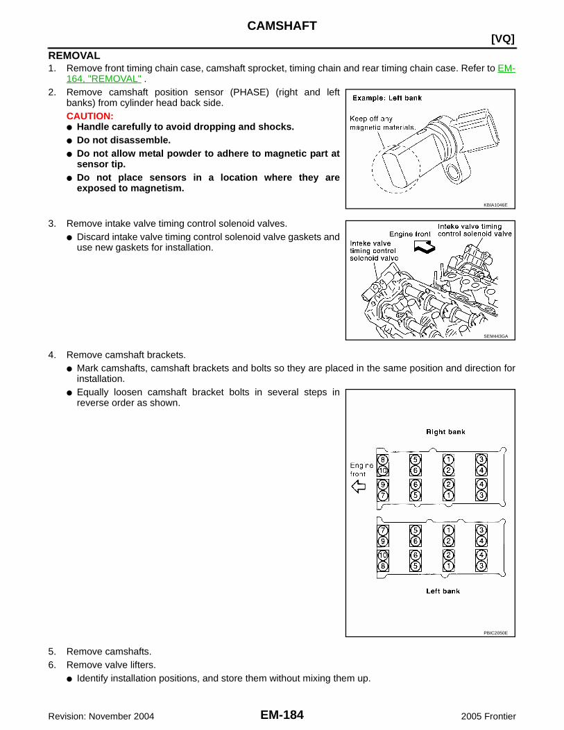
EM-184Revision: November 2004
[VQ]CAMSHAFT
2005 Frontier
REMOVAL1. Remove front timing chain case, camshaft sprocket, timing chain and rear timing chain case. Refer to EM-
164, "REMOVAL" .2. Remove camshaft position sensor (PHASE) (right and left
banks) from cylinder head back side.CAUTION:● Handle carefully to avoid dropping and shocks.● Do not disassemble.● Do not allow metal powder to adhere to magnetic part at
sensor tip.● Do not place sensors in a location where they are
exposed to magnetism.
3. Remove intake valve timing control solenoid valves.● Discard intake valve timing control solenoid valve gaskets and
use new gaskets for installation.
4. Remove camshaft brackets.● Mark camshafts, camshaft brackets and bolts so they are placed in the same position and direction for
installation.● Equally loosen camshaft bracket bolts in several steps in
reverse order as shown.
5. Remove camshafts.6. Remove valve lifters.
● Identify installation positions, and store them without mixing them up.
KBIA1046E
SEM443GA
PBIC2050E

CAMSHAFT
EM-185
[VQ]
C
D
E
F
G
H
I
J
K
L
M
A
EM
Revision: November 2004 2005 Frontier
7. Remove timing chain tensioner (secondary) from cylinder head.● Remove timing chain tensioner (secondary) with its stopper
pin attached.NOTE:Stopper pin was attached when timing chain (secondary) wasremoved.
INSPECTION AFTER REMOVALCamshaft Runout1. Put V-block on precise flat table, and support No. 2 and 4 journal
of camshaft.CAUTION:Do not support journal No. 1 (on the side of camshaftsprocket) because it has a different diameter from the otherthree locations.
2. Set dial indicator vertically to No. 3 journal.3. Turn camshaft to one direction with hands, and measure the
camshaft runout on dial indicator. (Total indicator reading)
4. If it exceeds the limit, replace camshaft.
Camshaft Cam Height1. Measure the camshaft cam height with micrometer.
2. If wear exceeds the limit, replace camshaft.
Camshaft Journal Oil ClearanceCAMSHAFT JOURNAL DIAMETER● Measure the outer diameter of camshaft journal with microme-
ter.
CAMSHAFT BRACKET INNER DIAMETER● Tighten camshaft bracket bolt with the specified torque. Refer to EM-188, "INSTALLATION" for the tight-
ening procedure.
PBIC2111E
Standard : Less than 0.02 mm (0.0008 in)Limit : 0.05 mm (0.0020 in)
PBIC0929E
Standard:Intake : 45.465 - 45.655 mm (1.7900 - 1.7974 in)Exhaust : 45.075 - 45.265 mm (1.7746 - 1.7821 in)
Limit:Intake : 45.265 mm (1.7821 in)Exhaust : 44.875 mm (1.7667 in)
EMQ0072D
Standard:No. 1 : 25.935 - 25.955 mm (1.0211 - 1.0218 in)No. 2, 3, 4 : 23.445 - 23.465 mm (0.9230 - 0.9238 in)
PBIC0040E

EM-186Revision: November 2004
[VQ]CAMSHAFT
2005 Frontier
● Measure the inner diameter “A” of camshaft bracket with boregauge.
CAMSHAFT JOURNAL OIL CLEARANCE● (Oil clearance) = (Camshaft bracket inner diameter) – (Camshaft journal diameter).
● If the calculated value exceeds the limit, replace either or both camshaft and cylinder head.NOTE:Camshaft bracket cannot be replaced as a single part, because it is machined together with cylinder head.Replace whole cylinder head assembly.
Camshaft End Play● Install dial indicator in thrust direction on front end of camshaft.
Measure the end play of dial indicator when camshaft is movedforward/backward (in direction to axis).
● Measure the following parts if out of the limit.– Dimension “A” for camshaft No. 1 journal
– Dimension “B” for cylinder head No. 1 journal bearing
● Refer to the standards above, and then replace camshaft and/orcylinder head.
Camshaft Sprocket Runout1. Put V-block on precise flat table, and support No. 2 and 4 journal of camshaft.
CAUTION:Do not support journal No. 1 (on the side of camshaft sprocket) because it has a different diameterfrom the other three locations.
Standard:No. 1 : 26.000 - 26.021 mm (1.0236 - 1.0244 in)No. 2, 3, 4 : 23.500 - 23.521 mm (0.9252 - 0.9260 in)
PBIC1645E
Standard:No. 1 : 0.045 - 0.086 mm (0.0018 - 0.0034 in)No. 2, 3, 4 : 0.035 - 0.076 mm (0.0014 - 0.0030 in)
Limit : 0.15 mm (0.0059 in)
Standard : 0.115 - 0.188 mm (0.0045 - 0.0074 in)Limit : 0.24 mm (0.0094 in)
SEM864E
Standard : 27.500 - 27.548 mm (1.0827 - 1.0846 in)
Standard : 27.360 - 27.385 mm (1.0772 - 1.0781 in)
KBIA2404J
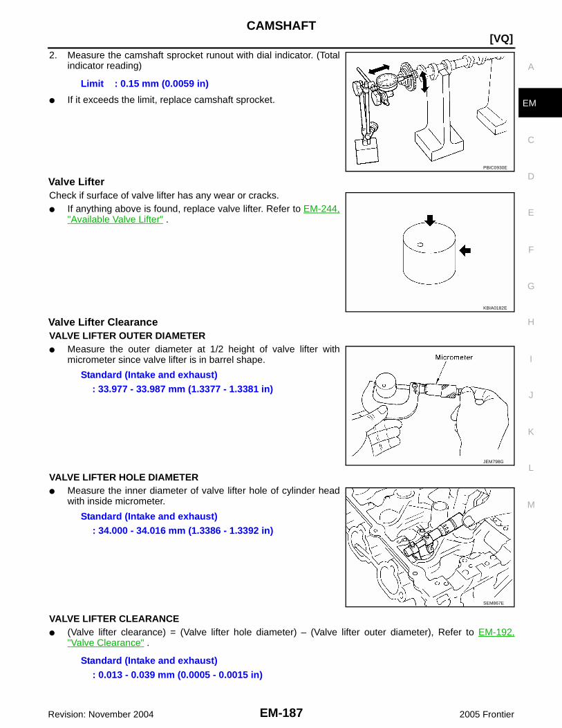
CAMSHAFT
EM-187
[VQ]
C
D
E
F
G
H
I
J
K
L
M
A
EM
Revision: November 2004 2005 Frontier
2. Measure the camshaft sprocket runout with dial indicator. (Totalindicator reading)
● If it exceeds the limit, replace camshaft sprocket.
Valve LifterCheck if surface of valve lifter has any wear or cracks.● If anything above is found, replace valve lifter. Refer to EM-244,
"Available Valve Lifter" .
Valve Lifter ClearanceVALVE LIFTER OUTER DIAMETER● Measure the outer diameter at 1/2 height of valve lifter with
micrometer since valve lifter is in barrel shape.
VALVE LIFTER HOLE DIAMETER● Measure the inner diameter of valve lifter hole of cylinder head
with inside micrometer.
VALVE LIFTER CLEARANCE● (Valve lifter clearance) = (Valve lifter hole diameter) – (Valve lifter outer diameter), Refer to EM-192,
"Valve Clearance" .
Limit : 0.15 mm (0.0059 in)
PBIC0930E
KBIA0182E
Standard (Intake and exhaust): 33.977 - 33.987 mm (1.3377 - 1.3381 in)
JEM798G
Standard (Intake and exhaust): 34.000 - 34.016 mm (1.3386 - 1.3392 in)
SEM867E
Standard (Intake and exhaust): 0.013 - 0.039 mm (0.0005 - 0.0015 in)

EM-188Revision: November 2004
[VQ]CAMSHAFT
2005 Frontier
● If the calculated value is out of the standard, referring to each standard of valve lifter outer diameter andvalve lifter hole diameter, replace either or both valve lifter and cylinder head.
INSTALLATION1. Install timing chain tensioners (secondary) on both sides of cyl-
inder head.● Install timing chain tensioner with its stopper pin attached.● Install timing chain tensioner with sliding part facing down-
ward on right-side cylinder head, and with sliding part facingupward on left-side cylinder head.
● Install new O-rings as shown.
2. Install valve lifters.● Install it in the original position.
3. Install camshafts.● Install camshaft with dowel pin attached to its front end face
on the exhaust side.
● Follow your identification marks made during removal, or fol-low the identification marks that are present on new cam-shafts for proper placement and direction.
● Install camshaft so that dowel pin hole and dowel pin on frontend face are positioned as shown. (No. 1 cylinder TDC on itscompression stroke)NOTE:● Large and small pin holes are located on front end face of
camshaft (INT), at intervals of 180°. Face small dia. sidepin hole upward (in cylinder head upper face direction).
● Though camshaft does not stop at the portion as shown, forthe placement of cam nose, it is generally accepted cam-shaft is placed for the same direction as shown.
PBIC2111E
KBIA1071E
Bank INT/EXH Dowel pinPaint marks Identification
markM1 M2
RHINT No Green No RE
EXH Yes No White RE
LHINT No Green No LH
EXH Yes No White LH KBIA1009E
PBIC2478E
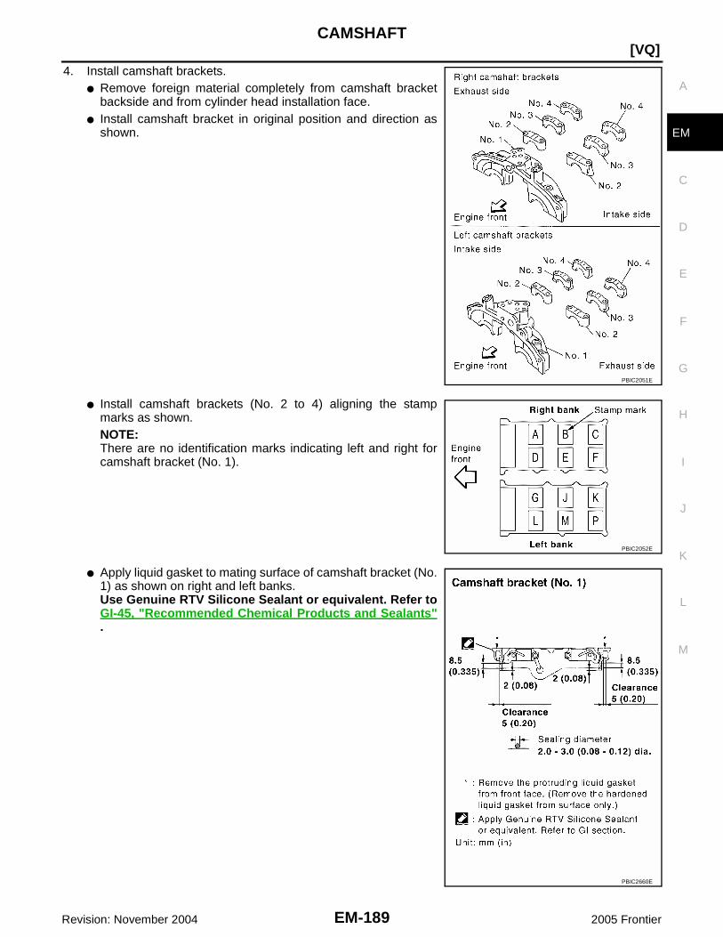
CAMSHAFT
EM-189
[VQ]
C
D
E
F
G
H
I
J
K
L
M
A
EM
Revision: November 2004 2005 Frontier
4. Install camshaft brackets.● Remove foreign material completely from camshaft bracket
backside and from cylinder head installation face.● Install camshaft bracket in original position and direction as
shown.
● Install camshaft brackets (No. 2 to 4) aligning the stampmarks as shown.NOTE:There are no identification marks indicating left and right forcamshaft bracket (No. 1).
● Apply liquid gasket to mating surface of camshaft bracket (No.1) as shown on right and left banks.Use Genuine RTV Silicone Sealant or equivalent. Refer toGI-45, "Recommended Chemical Products and Sealants".
PBIC2051E
PBIC2052E
PBIC2660E

EM-190Revision: November 2004
[VQ]CAMSHAFT
2005 Frontier
5. Tighten camshaft bracket bolts in the following steps, in numeri-cal order as shown.
6. Measure the difference in levels between front end faces ofcamshaft bracket (No. 1) and cylinder head.
● Measure two positions (both intake and exhaust side) for asingle bank.
● If the measured value is out of the standard, re-install cam-shaft bracket (No. 1).
7. Check and adjust the valve clearance. Refer to EM-192, "Valve Clearance" .8. Installation of the remaining components is in the reverse order of removal.
Camshaft bracket boltsStep 1 (bolts 7 - 10) : 1.96 N·m (0.2 kg-m, 17 in-lb)Step 2 (bolts 1 - 6) : 1.96 N·m (0.2 kg-m, 17 in-lb)Step 3 : 5.88 N·m (0.6 kg-m, 52 in-lb)Step 4 : 10.4 N·m (1.1 kg-m, 92 in-lb)
PBIC2050E
Standard : –0.14 to 0.14 mm (–0.0055 to 0.0055 in)
EMQ0044D

CAMSHAFT
EM-191
[VQ]
C
D
E
F
G
H
I
J
K
L
M
A
EM
Revision: November 2004 2005 Frontier
INSPECTION AFTER INSTALLATIONInspection of Camshaft Sprocket (INT) Oil GrooveCAUTION:● Perform this inspection only when DTC P0011 or P0021 are detected in self-diagnostic results of
CONSULT-II and it is directed according to inspection procedure of EC section. Refer to EC-681,"DIAGNOSTIC TEST MODE II — SELF-DIAGNOSTIC RESULTS" .
● Check when engine is cold so as to prevent burns from any splashing engine oil.1. Check the engine oil level. Refer to LU-18, "ENGINE OIL" .2. Perform the following procedure so as to prevent the engine from being unintentionally started while
checking.a. Release fuel pressure. Refer to EC-708, "FUEL PRESSURE RELEASE" .b. Disconnect ignition coil and injector harness connectors.3. Remove intake valve timing control solenoid valve. Refer to EM-184, "REMOVAL" .4. Crank the engine, and then make sure that engine oil comes out
from camshaft bracket (No. 1) oil hole. End crank after checking.WARNING:Be careful not to touch rotating parts (drive belts, idler pul-ley, and crankshaft pulley, etc.).CAUTION:Engine oil may squirt from intake valve timing control sole-noid valve installation hole during cranking. Use a shopcloth to prevent the engine components and the vehicle. Donot allow engine oil to get on rubber components such asdrive belt or engine mount insulators. Immediately wipe offany splashed engine oil.
● Clean oil groove between oil strainer and intake valve timing control solenoid valve if engine oil does notcome out from camshaft bracket (No. 1) oil hole. Refer to LU-16, "LUBRICATION SYSTEM" .
5. Remove components between intake valve timing control solenoid valve and camshaft sprocket (INT),and then check each oil groove for clogging.● Clean oil groove if necessary. Refer to LU-16, "LUBRICATION SYSTEM" .
6. After inspection, install removed parts.
Inspection for LeaksThe following are procedures for checking fluid leaks, lubricant leaks and exhaust gases leaks.● Before starting engine, check oil/fluid levels including engine coolant and engine oil. If less than required
quantity, fill to the specified level. Refer to MA-11, "RECOMMENDED FLUIDS AND LUBRICANTS" .● Use procedure below to check for fuel leakage.– Turn ignition switch “ON” (with engine stopped). With fuel pressure applied to fuel piping, check for fuel
leakage at connection points.– Start engine. With engine speed increased, check again for fuel leakage at connection points.● Run engine to check for unusual noise and vibration.
NOTE:If hydraulic pressure inside timing chain tensioner drops after removal/installation, slack in the guide maygenerate a pounding noise during and just after engine start. However, this is normal. Noise will stop afterhydraulic pressure rises.
● Warm up engine thoroughly to make sure there is no leakage of fuel, exhaust gases, or any oil/fluidsincluding engine oil and engine coolant.
● Bleed air from lines and hoses of applicable lines, such as in cooling system.● After cooling down engine, again check oil/fluid levels including engine oil and engine coolant. Refill to the
specified level, if necessary.
PBIC2869E

EM-192Revision: November 2004
[VQ]CAMSHAFT
2005 Frontier
Summary of the inspection items:
* Transmission/transaxle/CVT fluid, power steering fluid, brake fluid, etc.
Valve Clearance EBS00P4X
INSPECTIONIn cases of removing/installing or replacing camshaft and valve-related parts, or of unusual engine conditions due to changes invalve clearance (found malfunctions during stating, idling or causingnoise), perform inspection as follows:
1. Remove rocker covers (right and left banks). Refer to EM-149, "Removal and Installation" .2. Measure the valve clearance as follows:a. Set No. 1 cylinder at TDC of its compression stroke.
● Rotate crankshaft pulley clockwise to align timing mark(grooved line without color) with timing indicator.
● Make sure that intake and exhaust cam noses on No. 1 cylin-der (engine front side of right bank) are located as shown.
● If not, rotate crankshaft one revolution (360°) and align asshown.
Item Before starting engine Engine running After engine stopped
Engine coolant Level Leakage Level
Engine oil Level Leakage Level
Other oils and fluid* Level Leakage Level
Fuel Leakage Leakage Leakage
SEM713A
KBIA1717J
SEM418G

CAMSHAFT
EM-193
[VQ]
C
D
E
F
G
H
I
J
K
L
M
A
EM
Revision: November 2004 2005 Frontier
b. Use feeler gauge, measure the clearance between valve lifterand camshaft.
Valve clearance:Unit: mm (in)
*: Approximately 80°C (176°F)
● By referring to the figure, measure the valve clearances atlocations marked “×” as shown (locations indicated in the fig-ure) with feeler gauge.
● No. 1 cylinder at compression TDC
c. Rotate crankshaft by 240° clockwise (when viewed from enginefront) to align No. 3 cylinder at TDC of its compression stroke.NOTE:Crankshaft pulley bolt flange has a stamped line every 60°. Theycan be used as a guide to rotation angle.
SEM139D
Cold Hot * (reference data)
Intake 0.26 - 0.34 (0.010 - 0.013) 0.304 - 0.416 (0.012 - 0.016)
Exhaust 0.29 - 0.37 (0.011 - 0.015) 0.308 - 0.432 (0.012 - 0.017)
Measuring position (right bank) No. 1 CYL. No. 3 CYL. No. 5 CYL.
No. 1 cylinder atcompression TDC
EXH ×
INT ×
Measuring position (left bank) No. 2 CYL. No. 4 CYL. No. 6 CYL.
No. 1 cylinder atcompression TDC
INT ×
EXH ×
PBIC2054E
PBIC2916E

EM-194Revision: November 2004
[VQ]CAMSHAFT
2005 Frontier
● By referring to the figure, measure the valve clearances atlocations marked “×” as shown in the table below (locationsindicated in the figure) with feeler gauge.
● No. 3 cylinder at compression TDC
d. Rotate crankshaft by 240° clockwise (when viewed from enginefront) to align No. 5 cylinder at TDC of compression stroke.
● By referring to the figure, measure the valve clearances atlocations marked “×” as shown in the table below (locationsindicated in the figure) with feeler gauge.
● No. 5 cylinder at compression TDC
Measuring position (right bank) No. 1 CYL. No. 3 CYL. No. 5 CYL.
No. 3 cylinder atcompression TDC
EXH ×
INT ×
Measuring position (left bank) No. 2 CYL. No. 4 CYL. No. 6 CYL.
No. 3 cylinder atcompression TDC
INT ×
EXH ×
PBIC2055E
PBIC2916E
Measuring position (right bank) No. 1 CYL. No. 3 CYL. No. 5 CYL.
No. 5 cylinder atcompression TDC
EXH ×
INT ×
Measuring position (left bank) No. 2 CYL. No. 4 CYL. No. 6 CYL.
No. 5 cylinder atcompression TDC
INT ×
EXH ×
PBIC2056E
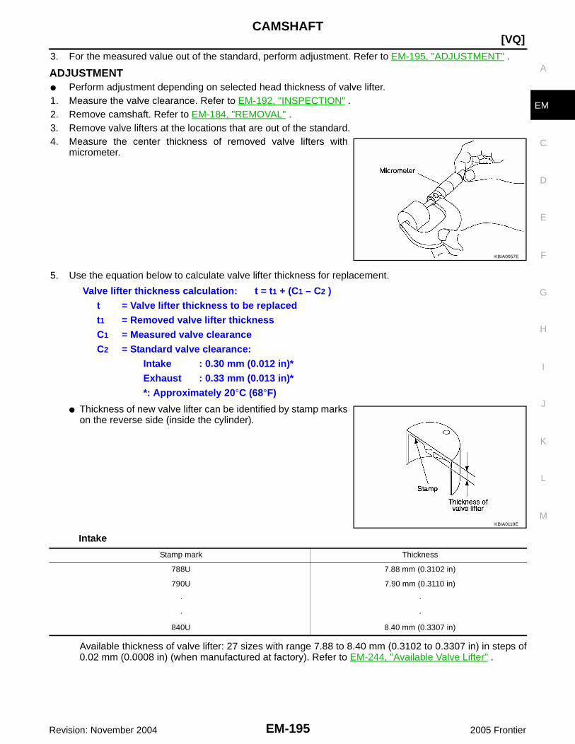
CAMSHAFT
EM-195
[VQ]
C
D
E
F
G
H
I
J
K
L
M
A
EM
Revision: November 2004 2005 Frontier
3. For the measured value out of the standard, perform adjustment. Refer to EM-195, "ADJUSTMENT" .
ADJUSTMENT● Perform adjustment depending on selected head thickness of valve lifter.1. Measure the valve clearance. Refer to EM-192, "INSPECTION" .2. Remove camshaft. Refer to EM-184, "REMOVAL" .3. Remove valve lifters at the locations that are out of the standard.4. Measure the center thickness of removed valve lifters with
micrometer.
5. Use the equation below to calculate valve lifter thickness for replacement.
● Thickness of new valve lifter can be identified by stamp markson the reverse side (inside the cylinder).
Intake
Available thickness of valve lifter: 27 sizes with range 7.88 to 8.40 mm (0.3102 to 0.3307 in) in steps of0.02 mm (0.0008 in) (when manufactured at factory). Refer to EM-244, "Available Valve Lifter" .
KBIA0057E
Valve lifter thickness calculation: t = t1 + (C1 – C2 )t = Valve lifter thickness to be replacedt1 = Removed valve lifter thicknessC1 = Measured valve clearanceC2 = Standard valve clearance:
Intake : 0.30 mm (0.012 in)*Exhaust : 0.33 mm (0.013 in)**: Approximately 20°C (68°F)
KBIA0119E
Stamp mark Thickness
788U 7.88 mm (0.3102 in)
790U 7.90 mm (0.3110 in)
· ·
· ·
840U 8.40 mm (0.3307 in)

EM-196Revision: November 2004
[VQ]CAMSHAFT
2005 Frontier
Exhaust
Available thickness of valve lifter: 25 sizes with range 7.88 to 8.36 mm (0.3102 to 0.3291 in) in steps of0.02 mm (0.0008 in) (when manufactured at factory). Refer to EM-244, "Available Valve Lifter" .CAUTION:Install identification letter at the end and top, “U” and “N”, at each of proper positions. (Be care-ful of mis-installation between intake and exhaust.)
6. Install selected valve lifter.7. Install camshaft. Refer to EM-188, "INSTALLATION" .8. Manually turn crankshaft pulley a few turns.9. Make sure that the valve clearances for cold engine are within the specifications by referring to the speci-
fied values.10. Installation of the remaining components is in the reverse order of removal.11. Start the engine, and check for unusual noise and vibration.
Stamp mark Thickness
N788 7.88 mm (0.3102 in)
N790 7.90 mm (0.3110 in)
· ·
· ·
N836 8.36 mm (0.3291 in)

OIL SEAL
EM-197
[VQ]
C
D
E
F
G
H
I
J
K
L
M
A
EM
Revision: November 2004 2005 Frontier
OIL SEAL PFP:00100
Removal and Installation of Valve Oil Seal EBS00P4Y
REMOVAL1. Turn crankshaft until the cylinder requiring new oil seals is at TDC. This will prevent valve from dropping
into cylinder.2. Remove camshaft relating to valve oil seal to be removed. Refer to EM-184, "REMOVAL" .3. Remove valve lifters. Refer to EM-184, "REMOVAL" .4. Remove valve collet, valve spring retainer and valve spring
using Tool.CAUTION:When working, take care not to damage valve lifter holes.
● Compress valve spring using Tool attachment, adapter.Remove valve collet with magnet hand.
5. Remove valve oil seal using Tool.
INSTALLATION1. Apply new engine oil to new valve oil seal joint surface and seal lip.2. Press in valve oil seal to height "H" using Tool to specified
height.
NOTE:Dimension "H": height measured before valve spring seat instal-lation.
3. Installation of the remaining components is in the reverse orderof removal.
Tool numbers : KV10116200 (J-26336-B): KV10115900 (J-26336-20): KV10109220 ( — )
WBIA0578E
Tool number : KV10107902 (J-38959)
WBIA0489E
Tool number : — (J-39386)
Intake and exhaust : 14.3 - 14.9 mm (0.563 - 0.587 in)
WBIA0490E

EM-198Revision: November 2004
[VQ]OIL SEAL
2005 Frontier
Removal and Installation of Front Oil Seal EBS00P4Z
REMOVAL1. Remove engine undercover using power tools.2. Remove drive belts. Refer to EM-122, "Removal" .3. Remove engine cooling fan assembly. Refer to CO-36, "ENGINE COOLING FAN" .4. Remove crankshaft pulley. Refer to EM-164, "REMOVAL" .5. Remove front oil seal using suitable tool.
CAUTION:Be careful not to damage front timing chain case and crank-shaft.
INSTALLATION1. Apply new engine oil to both oil seal lip and dust seal lip of new front oil seal.2. Install front oil seal.
● Install front oil seal so that each seal lip is oriented as shown.
● Press-fit until the height of front oil seal is level with themounting surface using suitable tool.
– Suitable drift: outer diameter 60 mm (2.36 in), inner diameter50 mm (1.97 in).
CAUTION:● Be careful not to damage front timing chain case and
crankshaft.● Press-fit straight and avoid causing burrs or tilting oil
seal.
3. Installation is in the reverse order of removal after this step.
Removal and Installation of Rear Oil Seal EBS00P50
REMOVAL1. Remove transmission assembly. Refer to MT-16, "REMOVAL" (FS5R30A), MT-65, "REMOVAL"
(FS6R31A, 2WD), MT-67, "REMOVAL" (FS6R31A, 4WD), AT-245, "REMOVAL" (2WD) or AT-249,"REMOVAL" (4WD).
PBIC2931E
SEM715A
PBIC2931E

OIL SEAL
EM-199
[VQ]
C
D
E
F
G
H
I
J
K
L
M
A
EM
Revision: November 2004 2005 Frontier
2. Remove rear oil seal with a suitable tool.CAUTION:Be careful not to damage crankshaft and cylinder block.
INSTALLATION1. Apply new engine oil to new rear oil seal joint surface and seal lip.2. Install rear oil seal so that each seal lip is oriented as shown.
● Press in rear oil seal to the position as shown.
● Press-fit rear oil seal using a suitable drift [outside diameter104 mm (4.09 in), inside diameter 88 mm (3.46 in)].CAUTION:● Be careful not to damage crankshaft and cylinder
block.● Press-fit oil seal straight to avoid causing burrs or tilt-
ing.● Do not touch grease applied onto oil seal lip.
3. Installation of the remaining components is in the reverse order of removal.
PBIC2932E
SEM715A
SBIA0281E
PBIC2933E
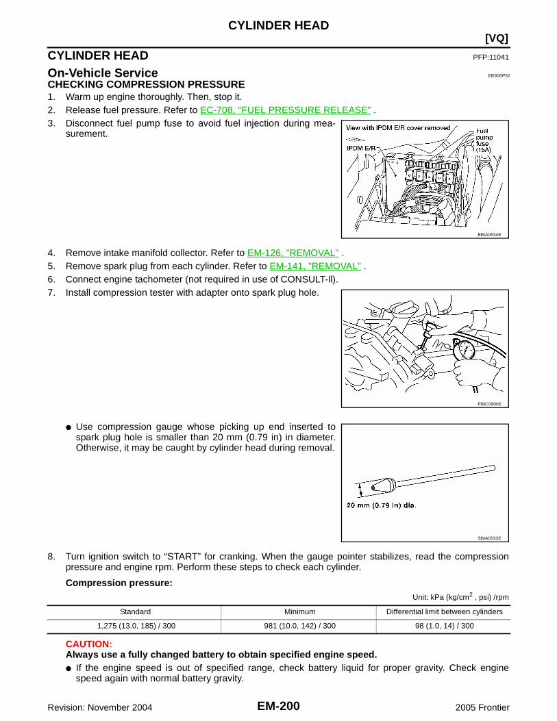
EM-200Revision: November 2004
[VQ]CYLINDER HEAD
2005 Frontier
CYLINDER HEAD PFP:11041
On-Vehicle Service EBS00P51
CHECKING COMPRESSION PRESSURE1. Warm up engine thoroughly. Then, stop it.2. Release fuel pressure. Refer to EC-708, "FUEL PRESSURE RELEASE" .3. Disconnect fuel pump fuse to avoid fuel injection during mea-
surement.
4. Remove intake manifold collector. Refer to EM-126, "REMOVAL" .5. Remove spark plug from each cylinder. Refer to EM-141, "REMOVAL" .6. Connect engine tachometer (not required in use of CONSULT-ll).7. Install compression tester with adapter onto spark plug hole.
● Use compression gauge whose picking up end inserted tospark plug hole is smaller than 20 mm (0.79 in) in diameter.Otherwise, it may be caught by cylinder head during removal.
8. Turn ignition switch to “START” for cranking. When the gauge pointer stabilizes, read the compressionpressure and engine rpm. Perform these steps to check each cylinder.
Compression pressure:Unit: kPa (kg/cm2 , psi) /rpm
CAUTION:Always use a fully changed battery to obtain specified engine speed.● If the engine speed is out of specified range, check battery liquid for proper gravity. Check engine
speed again with normal battery gravity.
BBIA0534E
PBIC0900E
SBIA0533E
Standard Minimum Differential limit between cylinders
1,275 (13.0, 185) / 300 981 (10.0, 142) / 300 98 (1.0, 14) / 300

CYLINDER HEAD
EM-201
[VQ]
C
D
E
F
G
H
I
J
K
L
M
A
EM
Revision: November 2004 2005 Frontier
● If compression pressure is below minimum value, check valve clearances and parts associated withcombustion chamber (valve, valve seat, piston, piston ring, cylinder bore, cylinder head, cylinder headgasket). After the checking, measure compression pressure again.
● If some cylinders have low compression pressure, pour small amount of engine oil into the spark plughole of the cylinder to re-check it for compression.
● If the added engine oil improves the compression, piston rings may be worn out or damaged. Check thepiston rings and replace if necessary.
● If the compression pressure remains at low level despite the addition of engine oil, valves may be mal-functioning. Check valves for damage. Replace valve or valve seat accordingly.
● If two adjacent cylinders have respectively low compression pressure and their compression remainslow even after the addition of engine oil, cylinder head gaskets are leaking. In such a case, replace cyl-inder head gaskets.
9. After inspection is completed, install removed parts.10. Start engine, and make sure that engine runs smoothly.11. Perform trouble diagnosis. If DTC appears, erase it. Refer to EC-710, "TROUBLE DIAGNOSIS" .
Removal and Installation EBS00P52
REMOVAL1. Remove camshaft. Refer to EM-184, "REMOVAL" .2. Remove intake manifold. Refer to EM-128, "REMOVAL" .3. Remove exhaust manifold. Refer to EM-130, "Removal and Installation" .4. Remove water inlet and thermostat assembly. Refer to CO-43, "REMOVAL" .5. Remove water outlet, water pipe and heater pipe. Refer to CO-45, "REMOVAL" .
1. Rubber plug 2. Cylinder head (left bank) 3. Cylinder head bolt
4. Cylinder head (right bank) 5. Harness bracket 6. Cylinder head gasket (right bank)
7. Cylinder head gasket (left bank)
PBIC2934E

EM-202Revision: November 2004
[VQ]CYLINDER HEAD
2005 Frontier
6. Remove cylinder head bolts in reverse order as shown usingcommercial service tool and power tool to remove cylinderheads (right and left banks).
7. Remove cylinder head gaskets.
INSPECTION AFTER REMOVALCylinder Head Bolts Outer Diameter● Cylinder head bolts are tightened by plastic zone tightening
method. Whenever the size difference between “d1” and “d2”exceeds the limit, replace them with new one.
● If reduction of outer diameter appears in a position other than“d2”, use it as “d2” point.
Cylinder Head DistortionNOTE:When performing this inspection, cylinder block distortion should be also checked. Refer to EM-234, "CYLIN-DER BLOCK DISTORTION" .1. Using suitable tool, wipe off oil, scale, gasket, sealant and carbon deposits from surface of cylinder head.
CAUTION:Do not allow gasket fragments to enter engine oil or engine coolant passages.
2. At each of several locations on bottom surface of cylinder head,measure the distortion in six directions.
● If it exceeds the limit, replace cylinder head.
Tool number : (J-24239-01)
PBIC2057E
Limit (“d1” – “d2”) : 0.11 mm (0.0043 in)
PBIC2480E
Limit : 0.1 mm (0.004 in)
SEM861E

CYLINDER HEAD
EM-203
[VQ]
C
D
E
F
G
H
I
J
K
L
M
A
EM
Revision: November 2004 2005 Frontier
INSTALLATION1. Install new cylinder head gasket.2. Turn crankshaft until No. 1 piston is set at TDC.
● Crankshaft key should line up with the right bank cylinder cen-ter line as shown.
3. Install cylinder head follow the steps below to tighten cylinderhead bolts in numerical order as shown.CAUTION:If cylinder head bolts re-used, check their outer diametersbefore installation. Refer to EM-202, "Cylinder Head BoltsOuter Diameter" .
SEM532G
Step a : 98 N·m (10 kg-m, 72 ft-lb)Step b : Loosen to 0 N·m in the reverse order of
tightening.Step c : 39.2 N·m (4.0 kg-m, 29 ft-lb)Step d : 90° clockwiseStep e : 90° clockwise
PBIC2057E
WBIA0581E

EM-204Revision: November 2004
[VQ]CYLINDER HEAD
2005 Frontier
4. After installing cylinder head, measure distance between frontend faces of cylinder block and cylinder head (left and rightbanks).
● If the measured value is out of the standard, re-install cylinderhead.
5. Installation of the remaining parts is in the reverse order of removal.
INSPECTION AFTER INSTALLATIONInspection for LeaksThe following are procedures for checking fluid leaks, lubricant leaks and exhaust gases leaks.● Before starting engine, check oil/fluid levels including engine coolant and engine oil. If less than required
quantity, fill to the specified level. Refer to MA-11, "RECOMMENDED FLUIDS AND LUBRICANTS" .● Use procedure below to check for fuel leakage.– Turn ignition switch “ON” (with engine stopped). With fuel pressure applied to fuel piping, check for fuel
leakage at connection points.– Start engine. With engine speed increased, check again for fuel leakage at connection points.● Run engine to check for unusual noise and vibration.● Warm up engine thoroughly to make sure there is no leakage of fuel, exhaust gases, or any oil/fluids
including engine oil and engine coolant.● Bleed air from lines and hoses of applicable lines, such as in cooling system.● After cooling down engine, again check oil/fluid levels including engine oil and engine coolant. Refill to the
specified level, if necessary.
Summary of the inspection items:
* Transmission/transaxle/CVT fluid, power steering fluid, brake fluid, etc.
Standard : 14.1 - 14.9 mm (0.555 - 0.587 in)
EMQ0662D
Item Before starting engine Engine running After engine stopped
Engine coolant Level Leakage Level
Engine oil Level Leakage Level
Other oils and fluid* Level Leakage Level
Fuel Leakage Leakage Leakage
Exhaust gases — Leakage —

CYLINDER HEAD
EM-205
[VQ]
C
D
E
F
G
H
I
J
K
L
M
A
EM
Revision: November 2004 2005 Frontier
Disassembly and Assembly EBS00P53
DISASSEMBLY1. Remove spark plug.2. Remove valve lifter.
● Identify installation positions, and store them without mixing them up.3. Remove valve collet.
● Compress valve spring and remove valve collet with magnethand using Tool.
CAUTION:When working, take care not to damage valve lifter holes.
4. Remove valve spring retainer, valve spring and valve spring seat.5. Push valve stem to combustion chamber side, and remove valve.
● Identify installation positions, and store them without mixing them up.
1. Valve lifter 2. Valve collet 3. Valve spring retainer
4. Valve spring 5. Valve oil seal 6. Valve spring seat
7. Valve guide 8. Spark plug 9. Spark plug tube
10. Cylinder head (right bank) 11. Valve seat 12. Valve (EXH)
13. Valve (INT) 14. Cylinder head (left bank)
PBIC2637E
Tool numbers : KV10109220 ( — ): KV10116200 (J-26336-A): KV10115900 (J-26336-20)
WBIA0578E

EM-206Revision: November 2004
[VQ]CYLINDER HEAD
2005 Frontier
6. Remove valve oil seals using Tool.
7. If valve seat must be replaced, refer to EM-209, "VALVE SEAT REPLACEMENT" .8. If valve guide must be replaced, refer to EM-208, "VALVE GUIDE REPLACEMENT" .9. Remove spark plug tube, as necessary.
● Using pair of pliers, pull spark plug tube out of cylinder head.CAUTION:● Take care not to damage cylinder head.● Once removed, spark plug tube will be deformed and cannot be reused. Do not remove it unless
absolutely necessary.
ASSEMBLY1. When valve guide is removed, install it. Refer to EM-208, "VALVE GUIDE REPLACEMENT" .2. When valve seat is removed, install it. Refer to EM-209, "VALVE SEAT REPLACEMENT" .3. Install valve oil seals using Tool.
4. Install valve spring seat.5. Install valves.
● Install it in the original position.NOTE:Larger diameter valves are for intake side.
6. Install valve spring (uneven pitch type).● Install narrow pitch end (paint mark) to cylinder head side
(valve spring seat side).● Intake side and exhaust side valve springs are different.
Install them referring to the following paint mark collar.
7. Install valve spring retainer.
Tool number : KV10107902 (J-38959)
WBIA0489E
Tool number : — (J-39386)
Height "H" (Without valve spring seat installed)Intake and exhaust : 14.3 - 14.9 mm (0.563 - 0.587 in)
WBIA0490E
Paint mark collarIntake : WhiteExhaust : White
SEM085D

CYLINDER HEAD
EM-207
[VQ]
C
D
E
F
G
H
I
J
K
L
M
A
EM
Revision: November 2004 2005 Frontier
8. Install valve collet.● Compress valve spring using Tool, attachment and adapter
using Tool. Install valve collet with magnet hand.
CAUTION:When working, take care not to damage valve lifter holesor valve stems.
● Tap valve stem edge lightly with plastic hammer after installa-tion to check its installed condition.
9. Install valve lifter.● Install it in the original position.
10. Install spark plug tube.● Press-fit spark plug tube as follows:
a. Remove old liquid gasket adhering to cylinder head mounting hole.b. Apply sealant to area within approximately 12 mm (0.47 in) from edge of spark plug tube press-fit side.
Use Genuine High Strength Locking Sealant or equivalent. Refer to GI-45, "Recommended Chemi-cal Products and Sealants" .
c. Press-fit spark plug tube so that its height “H” is as specified inthe figure using suitable drift.
CAUTION:● When press-fitting, take care not to deform spark plug
tube.● After press-fitting, wipe off liquid gasket protruding onto
cylinder-head upper face.11. Install spark plug.
Inspection After Disassembly EBS00P54
VALVE DIMENSIONS● Check dimensions of each valve. For dimensions, refer to EM-207, "VALVE DIMENSIONS" .● If dimensions are out of the standard, replace valve and check the valve seat contact. Refer to EM-209,
"VALVE SEAT CONTACT" .
VALVE GUIDE CLEARANCEValve Stem DiameterMeasure the diameter of valve stem with micrometer.
Valve Guide Inner DiameterMeasure the inner diameter of valve guide with inside micrometer.
Tool numbers : KV10109220 ( — ): KV10116200 (J-26336-A): KV10115900 (J-26336-20)
WBIA0578E
Standard press-fit height “H”: 38.1 - 39.1 mm (1.500 - 1.539 in)
PBIC2638E
StandardIntake : 5.965 - 5.980 mm (0.2348 - 0.2354 in)Exhaust : 5.955 - 5.970 mm (0.2344 - 0.2350 in)
SEM938C

EM-208Revision: November 2004
[VQ]CYLINDER HEAD
2005 Frontier
Valve Guide Clearance(Valve guide clearance) = (Valve guide inner diameter) – (Valve stem diameter).
● If the calculated value exceeds the limit, replace valve and/or valve guide. When valve guide must bereplaced, refer to EM-208, "VALVE GUIDE REPLACEMENT" .
VALVE GUIDE REPLACEMENTWhen valve guide is removed, replace with oversized [0.2 mm (0.008 in)] valve guide.1. To remove valve guide, heat cylinder head to 110° to 130°C
(230° to 266°F) by soaking in heated oil.
2. Drive out valve guide with a press [under a 20 kN (2 ton, 2.2 USton, 2.0 Imp ton) pressure] or hammer and valve guide drift(commercial service tool).CAUTION:Cylinder head contains heat. When working, wear protec-tive equipment to avoid getting burned.
3. Ream cylinder head valve guide hole; using suitable reamer.
StandardIntake and Exhaust : 6.000 - 6.018 mm (0.2362 - 0.2369 in)
Valve guide clearance:Standard
Intake : 0.020 - 0.053 mm (0.0008 - 0.0021 in)Exhaust : 0.030 - 0.063 mm (0.0012 - 0.0025 in)
LimitIntake : 0.08 mm (0.003 in)Exhaust : 0.09 mm (0.004 in)
SEM008A
SEM931C
Valve guide hole diameter (for service parts):Intake and exhaust
: 10.175 - 10.196 mm (0.4006 - 0.4014 in)
SEM932C

CYLINDER HEAD
EM-209
[VQ]
C
D
E
F
G
H
I
J
K
L
M
A
EM
Revision: November 2004 2005 Frontier
4. Heat cylinder head to 110° to 130°C (230° to 266°F) by soakingin heated oil.
5. Press valve guide from camshaft side to the dimensions asshown using suitable tool.
CAUTION:Cylinder head contains heat. When working, wear protec-tive equipment to avoid getting burned.
6. Apply reamer finish to valve guide using suitable reamer.
VALVE SEAT CONTACT● After confirming that the dimensions of valve guides and valves
are within the specifications, perform this procedure.● Apply prussian blue (or white lead) onto contacting surface of
valve seat to check the condition of the valve contact on the sur-face.
● Check if the contact area band is continuous all around the cir-cumference.
● If not, grind to adjust valve fitting and check again. If the contact-ing surface still has “NG” conditions even after the re-check,replace valve seat. Refer to EM-209, "VALVE SEAT REPLACE-MENT" .
VALVE SEAT REPLACEMENTWhen valve seat is removed, replace with oversized [0.5 mm (0.020 in)] valve seat.1. Bore out old seat until it collapses. Boring should not continue beyond the bottom face of the seat recess
in cylinder head. Set the machine depth stop to ensure this. Refer to EM-246, "Valve Seat" .CAUTION:Prevent to scratch cylinder head by excessive boring.
SEM008A
Projection “L”Intake and exhaust
: 12.6 - 12.8 mm (0.496 - 0.504 in)
SEM950E
Standard:Intake and exhaust
: 6.000 - 6.018 mm (0.2362 - 0.2369 in)
SEM932C
SBIA0322E

EM-210Revision: November 2004
[VQ]CYLINDER HEAD
2005 Frontier
2. Ream cylinder head recess diameter for service valve seat.
● Be sure to ream in circles concentric to valve guide center.This will enable valve to fit correctly.
3. Heat cylinder head to 110° to 130°C (230° to 266°F) by soakingin heated oil.
4. Provide valve seats cooled well with dry ice. Force fit valve seat into cylinder head.CAUTION:● Avoid directly touching cold valve seats.● Cylinder head contains heat. When working, wear protective equipment to avoid getting burned.
5. Finish seat to the specified dimensions using suitable tool. Referto EM-246, "Valve Seat" .CAUTION:When using valve seat cutter, firmly grip cutter handle withboth hands. Then, press on the contacting surface allaround the circumference to cut in a single drive. Improperpressure on with cutter or cutting many different times mayresult in staged valve seat.
6. Using compound, grind to adjust valve fitting.7. Check again for normal contact. Refer to EM-209, "VALVE SEAT CONTACT" .
VALVE SPRING SQUARENESS● Set try square along the side of valve spring and rotate spring.
Measure the maximum clearance between the top face of springand try square.
● If it exceeds the limit, replace valve spring.
Oversize [0.5 mm (0.020 in)]Intake : 38.500 - 38.516 mm (1.5157 - 1.5164 in)Exhaust : 32.700 - 32.716 mm (1.2874 - 1.2880 in)
SEM795A
SEM008A
SEM934C
Limit : 2.1 mm (0.083 in)
PBIC0080E

CYLINDER HEAD
EM-211
[VQ]
C
D
E
F
G
H
I
J
K
L
M
A
EM
Revision: November 2004 2005 Frontier
VALVE SPRING DIMENSIONS AND VALVE SPRING PRESSURE LOAD● Check valve spring pressure at the specified spring height.
● If the installation load or load with valve open is out of the standard, replace valve spring.
Standard:Intake and exhaust
Free height: 47.07 mm (1.8531 in)
Installation height: 37.00 mm (1.4567 in)
Installation load: 166 - 188 N (16.9 - 19.2 kg, 37 - 42 lb)
Height during valve open: 27.20 mm (1.0709 in)
Load with valve open: 373 - 421 N (38.0 - 42.9 kg, 84 - 95 lb)
SEM113

EM-212Revision: November 2004
[VQ]ENGINE ASSEMBLY
2005 Frontier
ENGINE ASSEMBLY PFP:10001
Removal and Installation EBS00P55
WARNING:● Situate vehicle on a flat and solid surface.● Place chocks at front and back of rear wheels.● For engines not equipped with engine slingers, attach proper slingers and bolts described in
PARTS CATALOG.CAUTION:● Always be careful to work safely, avoid forceful or uninstructed operations.
1. Rear engine mounting insulator 4x4 2. Rear engine mounting insulator 4x2 3. LH engine mounting bracket (upper)
4. LH heat shield plate 5. LH engine mounting insulator 6. LH engine mounting bracket (lower)
7. RH engine mounting bracket (lower) 8. RH engine mounting insulator (upper) 9. RH heat shield plate
10. RH engine mounting bracket (upper)
LBIA0432E

ENGINE ASSEMBLY
EM-213
[VQ]
C
D
E
F
G
H
I
J
K
L
M
A
EM
Revision: November 2004 2005 Frontier
● Do not start working until exhaust system and engine coolant are cooled sufficiently.● If items or work required are not covered by the engine section, refer to the applicable sections.● Always use the support point specified for lifting.● Use either 2-point lift type or separate type lift. If board-on type is used for unavoidable reasons,
support at the rear axle jacking point with transmission jack or similar tool before starting work, inpreparation for the backward shift of center of gravity.
● For supporting points for lifting and jacking point at rear axle, refer to GI-40, "Garage Jack andSafety Stand" .
REMOVALPreparation1. Drain engine coolant. Refer to MA-21, "DRAINING ENGINE COOLANT" .2. Partially drain A/T fluid. Refer to MA-32, "Changing the Automatic Transmission Fluid (ATF)" .3. Release fuel pressure. Refer to EC-708, "FUEL PRESSURE RELEASE" .4. Remove the engine hood. Refer to BL-13, "Removal and Installation of Hood Assembly" .5. Remove engine room cover using power tools.6. Remove the air duct and air cleaner case assembly. Refer to EM-124, "REMOVAL" .7. Disconnect vacuum hose between vehicle and engine and set it aside.8. Remove the radiator assembly and hoses. Refer to CO-33, "REMOVAL" .9. Remove the drive belts. Refer to EM-122, "Removal" .10. Remove the engine cooling fan. Refer to CO-36, "ENGINE COOLING FAN" .11. Disconnect the engine room harness from the engine side and set it aside for easier work.12. Disconnect the engine harness grounds.13. Disconnect the reservoir tank for power steering from engine and move it aside for easier work.14. Disconnect power steering oil pump from engine. Move it from its location and secure with a rope for eas-
ier work. Refer to PS-21, "REMOVAL" .15. Remove the A/C compressor bolts and set aside. Refer to MTC-101, "REMOVAL" (MTC).16. Disconnect brake booster vacuum line.17. Disconnect EVAP line.18. Disconnect the fuel hose at the engine side connection. Refer to EM-143, "REMOVAL" .19. Disconnect the heater hoses at cowl, and install plugs to avoid leakage of engine coolant.20. Remove the A/T oil level indicator and indicator tube.21. Remove front final drive assembly (4x4 only). Refer to FFD-14, "REMOVAL" .22. Remove three way catalyst. Refer to EM-130, "Removal and Installation" .23. Install engine slingers into left bank and right bank.
24. Remove transmission. Refer to MT-16, "REMOVAL" , MT-65,"REMOVAL" , MT-67, "REMOVAL" , AT-245, "REMOVAL" or AT-249, "REMOVAL" .
25. Lift with hoist and secure the engine in position.26. Remove engine assembly from vehicle, avoiding interference
with vehicle body.CAUTION:● Before and during this lifting, always check if any har-
nesses are left connected.27. Remove the parts that may restrict installation of engine to engine stand.
NOTE:The procedure is described assuming that you use a engine holding the surface, to which transmission isinstalled.
a. Remove drive plate.● Holding crankshaft pulley bolts, lock crankshaft to remove drive plate bolts.
Engine slinger torque: 28.0 N·m (2.9 kg-m, 21 ft-lb)
WBIA0624E

EM-214Revision: November 2004
[VQ]ENGINE ASSEMBLY
2005 Frontier
● Loosen bolts diagonally.CAUTION:● Be careful not to damage drive plate. Especially avoid
deforming and damaging of signal plate teeth (circum-ference position).
● Place the drive plate with signal plate surface facingother than downward.
● Keep magnetic materials away from signal plate.
CAUTION:Use an engine stand that has a load capacity [approximately 240kg (529 lb) or more] large enoughfor supporting the engine weight.● If the load capacity of the stand is not adequate, remove the following parts beforehand to
reduce the potential risk of overturning the stand.– Remove fuel tube and fuel injector assembly. Refer to EM-143, "REMOVAL" .– Remove intake manifold. Refer to EM-128, "REMOVAL" .– Remove rocker cover. Refer to EM-149, "Removal and Installation" .– Other removable brackets.CAUTION:Before removing the hanging chains, make sure the engine stand is stable and there is no risk ofoverturning.
28. Remove alternator. Refer to SC-38, "REMOVAL" .29. Remove engine mounting insulator bracket (upper) with power tool.
INSTALLATIONInstallation is in the reverse order of removal.
INSPECTION AFTER INSTALLATION● Before starting engine, check the levels of engine coolant, engine oil and working fluid. If less than
required quantity, fill to the specified level.● Use procedure below to check for fuel leakage.● Turn ignition switch ON (with engine stopped). With fuel pressure applied to fuel piping, check for fuel
leakage at connection points.● Start engine. With engine speed increased, check again for fuel leakage at connection points.● Run engine to check for unusual noise and vibration.● Warm up engine thoroughly to make sure there is no leakage of engine coolant, engine oil, working fluid,
fuel and exhaust gas.● Bleed air from passages in pipes and tubes of applicable lines, such as in cooling system.● After cooling down engine, again check amounts of engine coolant, engine oil and working fluid. Refill to
specified level, if necessary.● Summary of the inspection items:
*Transmission/transaxle/CVT fluid, power steering fluid, brake fluid, etc.
KBIA2491E
Item Before starting engine Engine running After engine stopped
Engine coolant Level Leakage Level
Engine oil Level Leakage Level
Working fluid Level Leakage Level
Fuel Leakage Leakage Leakage
Exhaust gas — Leakage —

CYLINDER BLOCK
EM-215
[VQ]
C
D
E
F
G
H
I
J
K
L
M
A
EM
Revision: November 2004 2005 Frontier
CYLINDER BLOCK PFP:11010
Disassembly and Assembly EBS00P56
1. Reinforcement plate 2. Drive plate (A/T models) 3. Rear oil seal
4. Sub harness 5. Knock sensor 6. Water connector
7. Cylinder block 8. Oil jet 9. Thrust bearing
10. Pilot converter (A/T models) 11. Main bearing 12. Crankshaft
13. Crankshaft key 14. Lower cylinder block 15. Lower cylinder block bolt
16. Connecting rod bolt 17. Connecting rod bearing cap 18. Connecting rod bearing
19. Connecting rod 20. Snap ring 21. Piston pin
22. Piston 23. Oil ring 24. Second ring
25. Top ring
WBIA0582E

EM-216Revision: November 2004
[VQ]CYLINDER BLOCK
2005 Frontier
DISASSEMBLY1. Remove engine assembly from vehicle. Refer to EM-213, "REMOVAL" .2. Remove both exhaust manifolds. Refer to EM-130, "Removal and Installation" .3. Lift engine, and mount it onto engine stand.
1. Cylinder block 2. Gasket 3. Cylinder block heater
4. Connector protector cap
PBIC2936E
PBIC0805E

CYLINDER BLOCK
EM-217
[VQ]
C
D
E
F
G
H
I
J
K
L
M
A
EM
Revision: November 2004 2005 Frontier
● A widely use engine stand can be used.CAUTION:Use engine stand that has a load capacity [approximately220 kg (441 lb) or more] large enough for supporting theengine weight.
4. Drain engine oil. Refer to LU-20, "Changing Engine Oil" .5. Drain engine coolant by removing water drain plugs from cylin-
der block left side at “A” and cylinder block front side at “B” asshown in the figure.NOTE:For Canada, “D” in the figure is not plug but block heater.
6. Remove drive plate (A/T models); using Tool.
● Loosen bolts in diagonal order.● Use TORX socket for drive plate bolts.
CAUTION:● Do not disassemble drive plate (A/T models).● Do not place drive plate (A/T models) with signal plate
facing down.● When handling signal plate, take care not to damage or
scratch it.● Handle signal plate in a manner that prevents it from
becoming magnetized.
7. Remove cylinder head. Refer to EM-201, "REMOVAL" .8. Remove sub harness, and remove knock sensors.
PBIC0085E
WLIA0020E
Tool number : KV10117700 (J-44716)
PBIC2938E

EM-218Revision: November 2004
[VQ]CYLINDER BLOCK
2005 Frontier
CAUTION:Carefully handle sensor avoiding shocks.
9. Remove pilot converter (A/T models) using Tool as necessary.
10. Remove piston and connecting rod assembly as follows:● Before removing piston and connecting rod assembly, check the connecting rod side clearance. Refer
to EM-231, "CONNECTING ROD SIDE CLEARANCE" .CAUTION:Be careful not to drop connecting rod bearing, and to scratch the surface.
11. Position crankshaft pin corresponding to connecting rod to be removed onto the bottom dead center.12. Remove connecting rod bearing cap.13. Push piston and connecting rod assembly out to the cylinder
head side using suitable tool.CAUTION:Be careful not to damage the cylinder wall and crankshaftpin, resulting from an interference of the connecting rod bigend.
14. Remove connecting rod bearings from connecting rod and connecting rod bearing cap.CAUTION:Identify installation position, and store them without mixing them up.
15. Remove piston rings form piston.● Before removing piston rings, check the piston ring side clearance. Refer to EM-232, "PISTON RING
SIDE CLEARANCE" .● Remove piston rings using piston ring expander or suitable
tool.CAUTION:● When removing piston rings, be careful not to damage
piston.● Be careful not to damage piston rings by expanding them
excessively.
16. Remove piston from connecting rod as follows:
Tool number : ST16610001 (J-23907)
WBIA0583E
PBIC2940E
PBIC0087E
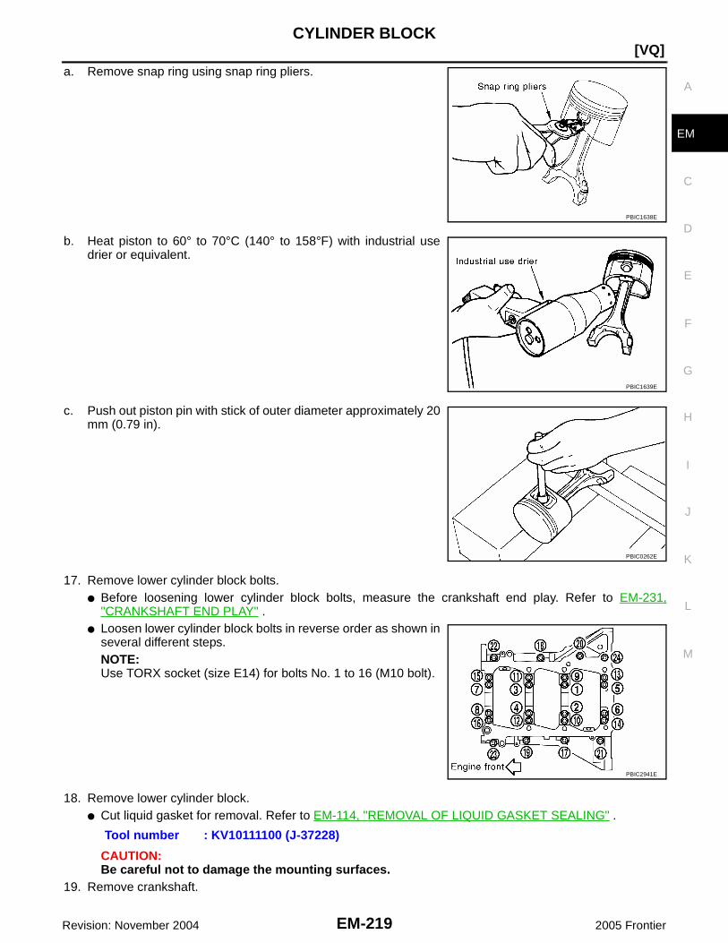
CYLINDER BLOCK
EM-219
[VQ]
C
D
E
F
G
H
I
J
K
L
M
A
EM
Revision: November 2004 2005 Frontier
a. Remove snap ring using snap ring pliers.
b. Heat piston to 60° to 70°C (140° to 158°F) with industrial usedrier or equivalent.
c. Push out piston pin with stick of outer diameter approximately 20mm (0.79 in).
17. Remove lower cylinder block bolts.● Before loosening lower cylinder block bolts, measure the crankshaft end play. Refer to EM-231,
"CRANKSHAFT END PLAY" .● Loosen lower cylinder block bolts in reverse order as shown in
several different steps.NOTE:Use TORX socket (size E14) for bolts No. 1 to 16 (M10 bolt).
18. Remove lower cylinder block.● Cut liquid gasket for removal. Refer to EM-114, "REMOVAL OF LIQUID GASKET SEALING" .
CAUTION:Be careful not to damage the mounting surfaces.
19. Remove crankshaft.
PBIC1638E
PBIC1639E
PBIC0262E
PBIC2941E
Tool number : KV10111100 (J-37228)

EM-220Revision: November 2004
[VQ]CYLINDER BLOCK
2005 Frontier
20. Pull rear oil seal out from rear end of crankshaft.NOTE:When replacing rear oil seal without removing lower cylinder block, use a suitable to pull the rear oil sealinstalled between crankshaft and cylinder block out.CAUTION:Be careful not to damage crankshaft and cylinder block.
21. Remove main bearings and thrust bearings from cylinder block and lower cylinder block.CAUTION:● Be careful not to drop main bearing, and to scratch the surface.● Identify installation positions, and store them without mixing them up.
22. Remove oil jet.
ASSEMBLY1. Fully air-blow engine coolant and engine oil passages in cylinder block, cylinder bore and crankcase to
remove any foreign material.CAUTION:Use a goggles to protect your eye.
2. Install each plug to cylinder block as shown.● Apply sealant to the thread of water drain plugs “A” and “B”.
Use Genuine RTV Silicone Sealant or equivalent. Refer toGI-45, "Recommended Chemical Products and Sealants".
● Apply sealant to the thread of plugs “C”.Use Genuine High Strength Thread Locking Sealant orequivalent. Refer to GI-45, "Recommended ChemicalProducts and Sealants" .
● Apply sealant to the thread of plug “D”.Use Anaerobic Liquid Gasket or equivalent. Refer to GI-45, "Recommended Chemical Products and Sealants" .NOTE:For Canada, “D” in the figure is not plug but block heater.Refer to EM-215, "Disassembly and Assembly" .
● Replace washers with new one.
● Tighten each plug as specified below.
Block Plug and Block Heater Installation
3. Install oil jet.
WLIA0020E
Part Washer Tightening Torque
A No 19.6 N·m (2.0 kg-m, 14 ft-lb)
BReuse
No9.8 N·m (1.0 kg-m, 87 in-lb)
New 6.0 N·m (0.61 kg-m, 53 in-lb)
C Yes 116 N·m (11.8 kg-m, 85 ft-lb)
DPlug
Yes62 N·m (6.3 kg-m, 46 ft-lb)
Block heater 73.5 N·m (7.5 kg-m, 54 ft-lb)

CYLINDER BLOCK
EM-221
[VQ]
C
D
E
F
G
H
I
J
K
L
M
A
EM
Revision: November 2004 2005 Frontier
● Insert oil jet dowel pin into cylinder block dowel pin hole, andtighten bolts.
4. Install main bearings and thrust bearings as follows:a. Remove dust, dirt, and engine oil on bearing mating surfaces of cylinder block and main bearing caps.b. Install thrust bearings to the both sides of the No. 3 journal hous-
ing on cylinder block.● Install thrust bearings with the oil groove facing crankshaft
arm (outside).● Install thrust bearing with a projection on one end on cylinder
block, Align projection with mating notch.
c. Install main bearings paying attention to the direction.● Main bearing with oil hole and groove goes on cylinder block.
The one without them goes on lower cylinder block.● Before installing main bearings, apply engine oil to the bear-
ing surface (inside). Do not apply engine oil to the back sur-face, but thoroughly clean it.
● When installing, align main bearing stopper protrusion to cut-out of cylinder block and lower cylinder block.
● Ensure the oil holes on cylinder block and those on the corre-sponding bearing are aligned.
5. Install crankshaft to cylinder block.● While turning crankshaft by hand, check that it turns smoothly.
6. Inspect the outer diameter of lower cylinder block bolt. Refer to EM-239, "LOWER CYLINDER BLOCKBOLT OUTER DIAMETER" .
7. Install lower cylinder block as follows:NOTE:Lower cylinder block cannot be replaced as a single part, because it is machined together with cylinderblock.
a. Apply a continuous bead of liquid gasket using Tool to lower cyl-inder block as shown.
Use Genuine RTV Silicone Sealant or equivalent. Refer toGI-45, "Recommended Chemical Products and Sealants" .CAUTION:After liquid gasket is applied, rear oil seal installation mustbe finished within 5 minutes. Therefore, the following pro-cedure must be performed quickly.
b. Tighten lower cylinder block as follows:
PBIC0898E
PBIC2968E
PBIC2969E
Tool number : WS39930000 ( — )
PBIC2942E

EM-222Revision: November 2004
[VQ]CYLINDER BLOCK
2005 Frontier
i. Apply new engine oil to threads and seat surfaces of the bolts.ii. Tighten M8 bolts in numerical order as shown from No. 17 to 24.
CAUTION:Wipe off completely any protruding liquid gasket on rear oilseal installation surface.NOTE:There are more processes to complete the tightening bolts.However stop procedure here to install rear oil seal.
c. Install rear oil seal. Refer to EM-199, "INSTALLATION" .d. Restart tightening of lower cylinder block bolts as follows:i. Tighten M10 bolts in numerical order as shown from No. 1 to 16.
NOTE:Use TORX socket (size E14) for bolts No. 1 to 16 (M10 bolt).
ii. Turn M10 bolts 90° clockwise in numerical order from No. 1 to16 using Tool.
CAUTION:Use angle wrench Tool to check tightening angle. Do notmake judgement by visual inspection.
● After installing the bolts, make sure that crankshaft can be rotated smoothly by hand.● Wipe off completely any protruding liquid gasket on front side of the engine.● Check the crankshaft end play. Refer to EM-231, "CRANKSHAFT END PLAY" .
8. Inspect the outer diameter of connecting rod bolt. Refer to EM-240, "CONNECTING ROD BOLT OUTERDIAMETER" .
9. Install piston to connecting rod as follows:a. Install new snap ring to the groove of piston rear side using suitable tool.
● Insert it fully into groove to install.b. Install piston to connecting rod.
● Using industrial use drier or similar tool, heat piston until piston pin can be pushed in by hand withoutexcess force [approx. 60° to 70 °C (140° to 158 °F)]. From the front to the rear, insert piston pin into pis-ton and connecting rod.
Bolts 17 - 24 : 22.1 N·m (2.3 kg-m, 16 ft-lb)
PBIC2941E
Bolts 1 - 16 : 35.3 N·m (3.6 kg-m, 26 ft-lb)
PBIC2941E
Tool number : KV10112100 (BT-8653-A)
WBIA0584E

CYLINDER BLOCK
EM-223
[VQ]
C
D
E
F
G
H
I
J
K
L
M
A
EM
Revision: November 2004 2005 Frontier
● Assemble so that the front mark on the piston head and thecylinder number on connecting rod are positioned as shown.
c. Install new snap ring to the groove of the piston front side.● Insert it fully into groove to install.● After installing, make sure that connecting rod moves
smoothly.
10. Install piston rings using piston ring expander or suitable tool.CAUTION:● When installing piston rings, be careful not to damage
piston.● Be careful not to damage piston rings by expending them
excessively.
● If there is stamped mark on ring, mount it with marked sideup.NOTE:If there is no stamp on ring, no specific orientation is requiredfor installation.
● Position each ring with the gap as shown referring to the pis-ton front mark.
● Check the piston ring side clearance. Refer to EM-232, "PISTON RING SIDE CLEARANCE" .11. Install connecting rod bearings to connecting rod and connecting rod bearing cap.
● Before installing connecting rod bearings, apply engine oil to the bearing surface (inside). Do not applyengine oil to the back surface, but thoroughly clean it.
SEM838F
PBIC0087E
Stamped mark:Top ring : —Second ring : R
SEM757G
PBIC0808E

EM-224Revision: November 2004
[VQ]CYLINDER BLOCK
2005 Frontier
● When installing, align connecting rod bearing stopper protru-sion with cutout of connecting rods and connecting rod bear-ing caps to install.
● Ensure the oil hole on connecting rod and that on the corre-sponding bearing are aligned.
12. Install piston and connecting rod assembly to crankshaft.13. Position crankshaft pin corresponding to connecting rod to be installed onto the bottom dead center.14. Apply engine oil sufficiently to the cylinder bore, piston and crankshaft pin journal.15. Match the cylinder position with the cylinder number on connecting rod to install.
NOTE:Be sure that front mark on piston head is facing front of engine.
16. Install piston with the front mark on the piston head facing thefront of engine using Tool.
CAUTION:Be careful not to damage the cylinder wall and crankshaftpin, resulting from an interference of the connecting rod bigend.
17. Install connecting rod bearing cap.● Match the stamped cylinder number marks on connecting rod
with those on connecting rod bearing cap to install.● Be sure that front mark on connecting rod bearing cap is fac-
ing front of engine.
18. Tighten connecting rod bolts as follows:a. Apply engine oil to the threads and seats of connecting rod bolts.b. Tighten connecting rod bolts.
PBIC2067E
Tool number : EM03470000 (J-8037)
WBIA0585E
PBIC0809E
Connecting rod bolt : 19.6 N·m (2.0 kg-m, 14 ft-lb)
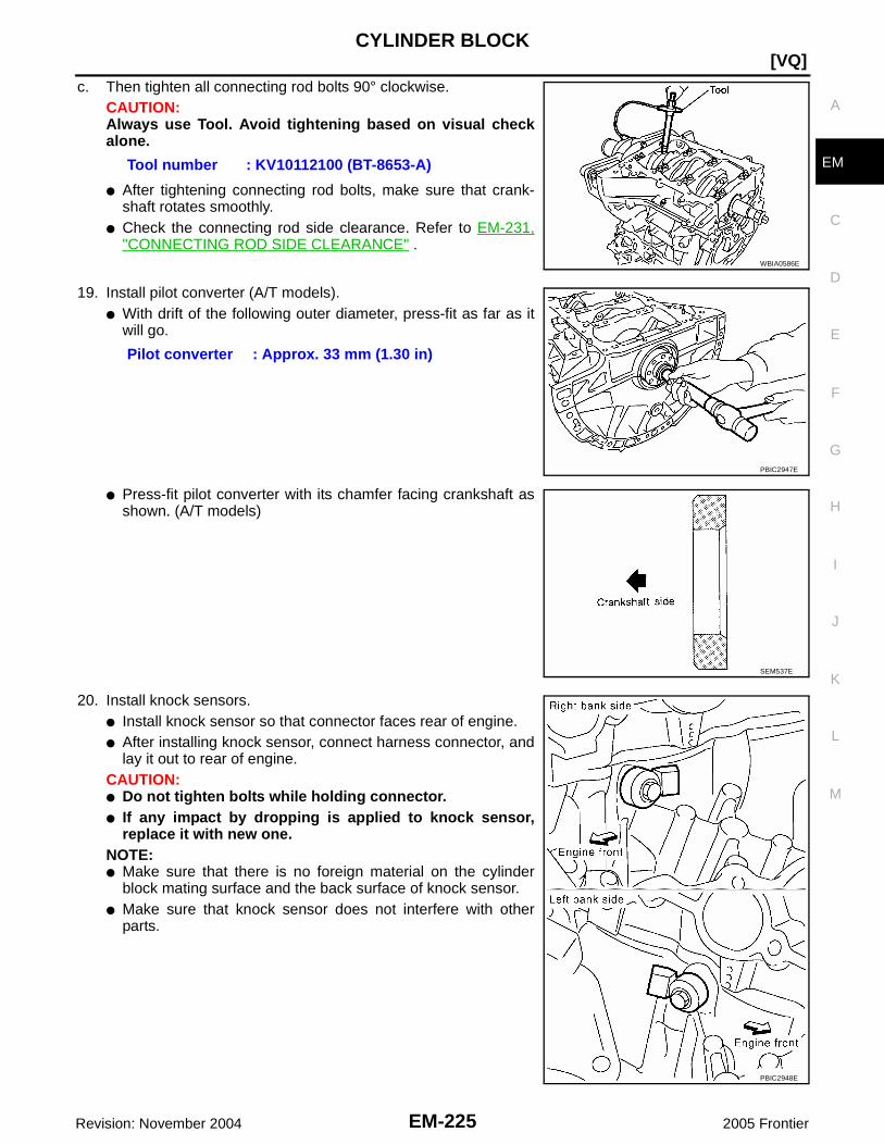
CYLINDER BLOCK
EM-225
[VQ]
C
D
E
F
G
H
I
J
K
L
M
A
EM
Revision: November 2004 2005 Frontier
c. Then tighten all connecting rod bolts 90° clockwise.CAUTION:Always use Tool. Avoid tightening based on visual checkalone.
● After tightening connecting rod bolts, make sure that crank-shaft rotates smoothly.
● Check the connecting rod side clearance. Refer to EM-231,"CONNECTING ROD SIDE CLEARANCE" .
19. Install pilot converter (A/T models).● With drift of the following outer diameter, press-fit as far as it
will go.
● Press-fit pilot converter with its chamfer facing crankshaft asshown. (A/T models)
20. Install knock sensors.● Install knock sensor so that connector faces rear of engine.● After installing knock sensor, connect harness connector, and
lay it out to rear of engine.CAUTION:● Do not tighten bolts while holding connector.● If any impact by dropping is applied to knock sensor,
replace it with new one.NOTE:● Make sure that there is no foreign material on the cylinder
block mating surface and the back surface of knock sensor.● Make sure that knock sensor does not interfere with other
parts.
Tool number : KV10112100 (BT-8653-A)
WBIA0586E
Pilot converter : Approx. 33 mm (1.30 in)
PBIC2947E
SEM537E
PBIC2948E
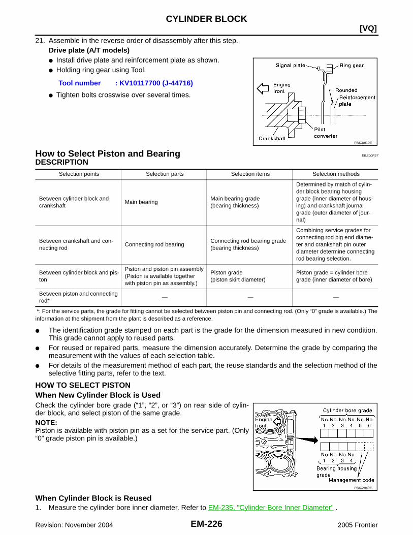
EM-226Revision: November 2004
[VQ]CYLINDER BLOCK
2005 Frontier
21. Assemble in the reverse order of disassembly after this step.Drive plate (A/T models)● Install drive plate and reinforcement plate as shown.● Holding ring gear using Tool.
● Tighten bolts crosswise over several times.
How to Select Piston and Bearing EBS00P57
DESCRIPTION
*: For the service parts, the grade for fitting cannot be selected between piston pin and connecting rod. (Only “0” grade is available.) Theinformation at the shipment from the plant is described as a reference.
● The identification grade stamped on each part is the grade for the dimension measured in new condition.This grade cannot apply to reused parts.
● For reused or repaired parts, measure the dimension accurately. Determine the grade by comparing themeasurement with the values of each selection table.
● For details of the measurement method of each part, the reuse standards and the selection method of theselective fitting parts, refer to the text.
HOW TO SELECT PISTONWhen New Cylinder Block is UsedCheck the cylinder bore grade (“1”, “2”, or “3”) on rear side of cylin-der block, and select piston of the same grade.NOTE:Piston is available with piston pin as a set for the service part. (Only“0” grade piston pin is available.)
When Cylinder Block is Reused1. Measure the cylinder bore inner diameter. Refer to EM-235, "Cylinder Bore Inner Diameter" .
Tool number : KV10117700 (J-44716)
PBIC0910E
Selection points Selection parts Selection items Selection methods
Between cylinder block andcrankshaft
Main bearingMain bearing grade(bearing thickness)
Determined by match of cylin-der block bearing housinggrade (inner diameter of hous-ing) and crankshaft journalgrade (outer diameter of jour-nal)
Between crankshaft and con-necting rod
Connecting rod bearingConnecting rod bearing grade(bearing thickness)
Combining service grades forconnecting rod big end diame-ter and crankshaft pin outerdiameter determine connectingrod bearing selection.
Between cylinder block and pis-ton
Piston and piston pin assembly(Piston is available togetherwith piston pin as assembly.)
Piston grade(piston skirt diameter)
Piston grade = cylinder boregrade (inner diameter of bore)
Between piston and connectingrod*
— — —
PBIC2949E

CYLINDER BLOCK
EM-227
[VQ]
C
D
E
F
G
H
I
J
K
L
M
A
EM
Revision: November 2004 2005 Frontier
2. Determine the bore grade by comparing the measurement withthe values under the cylinder bore inner diameter of the “PistonSelection Table”.
3. Select piston of the same grade.
Piston Selection TableUnit: mm (in)
NOTE:● Piston is available together with piston pin as assembly.● Piston pin (piston pin hole) grade is provided only for the parts installed at the plant. For service parts, no
piston pin grades can be selected. (Only “0” grade is available.)● No second grade mark is available on piston.
HOW TO SELECT CONNECTING ROD BEARINGWhen New Connecting Rod and Crankshaft are UsedCheck pin journal grade (“0”, “1”, or “2”) on front of crankshaft, andselect connecting rod bearing of the same grade.NOTE:There is no grading for connecting rod big end diameter.
When Crankshaft and Connecting Rod are Reused1. Measure the connecting rod big end diameter. Refer to EM-233, "CONNECTING ROD BIG END DIAME-
TER" .2. Make sure that the connecting rod big end diameter is within the standard value.3. Measure the crankshaft pin journal diameter. Refer to EM-237, "CRANKSHAFT PIN JOURNAL DIAME-
TER" .4. Determine the grade of crankshaft pin journal grade by corresponding to the measured dimension in
“Crankshaft pin journal diameter” column of “Connecting Rod Bearing Selection Table”.5. Select connecting rod bearing of the same grade.
Connecting Rod Bearing Selection TableUnit: mm (in)
PBIC2950E
Grade 1 2 (or no mark) 3
Cylinder bore inner diameter95.500 - 95.510
(3.7598 - 3.7602)95.510 - 95.520(3.7602 - 3.7606)
95.520 - 95.530(3.7606 - 3.7610)
Piston skirt diameter95.480 - 95.490
(3.7590 - 3.7594)95.490 - 95.500
(3.7594 - 3.7598)95.500 - 95.510
(3.7598 - 3.7602)
PBIC2951E
Connecting rod big end diameter 57.000 - 57.013 (2.2441 - 2.2446)
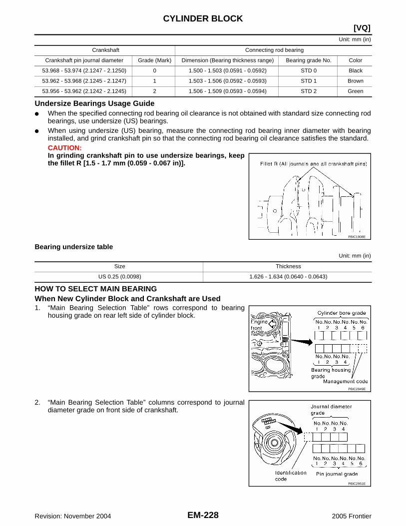
EM-228Revision: November 2004
[VQ]CYLINDER BLOCK
2005 Frontier
Unit: mm (in)
Undersize Bearings Usage Guide● When the specified connecting rod bearing oil clearance is not obtained with standard size connecting rod
bearings, use undersize (US) bearings.● When using undersize (US) bearing, measure the connecting rod bearing inner diameter with bearing
installed, and grind crankshaft pin so that the connecting rod bearing oil clearance satisfies the standard.CAUTION:In grinding crankshaft pin to use undersize bearings, keepthe fillet R [1.5 - 1.7 mm (0.059 - 0.067 in)].
Bearing undersize tableUnit: mm (in)
HOW TO SELECT MAIN BEARINGWhen New Cylinder Block and Crankshaft are Used1. “Main Bearing Selection Table” rows correspond to bearing
housing grade on rear left side of cylinder block.
2. “Main Bearing Selection Table” columns correspond to journaldiameter grade on front side of crankshaft.
Crankshaft Connecting rod bearing
Crankshaft pin journal diameter Grade (Mark) Dimension (Bearing thickness range) Bearing grade No. Color
53.968 - 53.974 (2.1247 - 2.1250) 0 1.500 - 1.503 (0.0591 - 0.0592) STD 0 Black
53.962 - 53.968 (2.1245 - 2.1247) 1 1.503 - 1.506 (0.0592 - 0.0593) STD 1 Brown
53.956 - 53.962 (2.1242 - 2.1245) 2 1.506 - 1.509 (0.0593 - 0.0594) STD 2 Green
PBIC1908E
Size Thickness
US 0.25 (0.0098) 1.626 - 1.634 (0.0640 - 0.0643)
PBIC2949E
PBIC2951E

CYLINDER BLOCK
EM-229
[VQ]
C
D
E
F
G
H
I
J
K
L
M
A
EM
Revision: November 2004 2005 Frontier
3. Select main bearing grade at the point where selected row and column meet in “Main Bearing SelectionTable”.
When Cylinder Block and Crankshaft are Reused1. Measure cylinder block main bearing housing inner diameter and crankshaft main journal diameter. Refer
to EM-235, "MAIN BEARING HOUSING INNER DIAMETER" and EM-236, "CRANKSHAFT MAIN JOUR-NAL DIAMETER" .
2. Correspond the measured dimension in “Cylinder block main bearing housing inner diameter” row of“Main Bearing Selection Table”.
3. Correspond the measured dimension in “Crankshaft main journal diameter” column of “Main BearingSelection Table”.
4. Select main bearing grade at the point where selected row and column meet in following selection table.
Main Bearing Selection Table
WBIA0625E

EM-230Revision: November 2004
[VQ]CYLINDER BLOCK
2005 Frontier
Main Bearing Grade Table (All Journals)
Undersize Bearing Usage Guide● When the specified main bearing oil clearance is not obtained with standard size main bearings, use
underside (US) bearing.● When using undersize (US) bearing, measure the main bearing inner diameter with bearing installed, and
grind main journal so that the main bearing oil clearance satisfies the standard.CAUTION:In grinding crankshaft main journal to use undersize bear-ings, keep the fillet R [1.5 - 1.7 mm (0.059 - 0.067 in)].
Bearing undersize tableUnit: mm (in)
Grade numberThickness
Unit: mm (in)Width
Unit: mm (in)Identification color Remarks
0 2.500 - 2.503 (0.0984 - 0.0985)
19.9 - 20.1(0.783 - 0.791)
Black
Grade is the same forupper and lower bear-ings.
1 2.503 - 2.506 (0.0985 - 0.0987) Brown
2 2.506 - 2.509 (0.0987 - 0.0988) Green
3 2.509 - 2.512 (0.0988 - 0.0989) Yellow
4 2.512 - 2.515 (0.0989 - 0.0990) Blue
5 2.515 - 2.518 (0.0990 - 0.0991) Pink
6 2.518 - 2.521 (0.0991 - 0.0993) Purple
7 2.521 - 2.524 (0.0993 - 0.0994) White
01UPR 2.503 - 2.506 (0.0985 - 0.0987) Brown
Grade is different forupper and lower bear-ings.
LWR 2.500 - 2.503 (0.0984 - 0.0985) Black
12UPR 2.506 - 2.509 (0.0987 - 0.0988) Green
LWR 2.503 - 2.506 (0.0985 - 0.0987) Brown
23UPR 2.509 - 2.512 (0.0988 - 0.0989) Yellow
LWR 2.506 - 2.509 (0.0987 - 0.0988) Green
34UPR 2.512 - 2.515 (0.0989 - 0.0990) Blue
LWR 2.509 - 2.512 (0.0988 - 0.0989) Yellow
45UPR 2.515 - 2.518 (0.0990 - 0.0991) Pink
LWR 2.512 - 2.515 (0.0989 - 0.0990) Blue
56UPR 2.518 - 2.521 (0.0991 - 0.0993) Purple
LWR 2.515 - 2.518 (0.0990 - 0.0991) Pink
67UPR 2.521 - 2.524 (0.0993 - 0.0994) White
LWR 2.518 - 2.521 (0.0991 - 0.0993) Purple
PBIC1908E
Size Thickness
US 0.25 (0.0098) 2.633 - 2.641 (0.1037 - 0.1040)

CYLINDER BLOCK
EM-231
[VQ]
C
D
E
F
G
H
I
J
K
L
M
A
EM
Revision: November 2004 2005 Frontier
Inspection After Disassembly EBS00P58
CRANKSHAFT END PLAY● Measure the clearance between thrust bearings and crankshaft
arm when crankshaft is moved fully forward or backward withdial indicator.
● If the measured value exceeds the limit, replace thrust bearings,and measure again. If it still exceeds the limit, replace crank-shaft also.
CONNECTING ROD SIDE CLEARANCE● Measure the side clearance between connecting rod and crank-
shaft arm with feeler gauge.
● If the measured value exceeds the limit, replace connecting rod,and measure again. If it still exceeds the limit, replace crank-shaft also.
PISTON TO PISTON PIN OIL CLEARANCEPiston Pin Hole DiameterMeasure the inner diameter of piston pin hole with inside microme-ter.
Piston Pin Outer DiameterMeasure the outer diameter of piston pin with micrometer.
Piston to Piston Pin Oil Clearance(Piston to piston pin oil clearance) = (Piston pin hole diameter) – (Piston pin outer diameter)
● If the calculated value is out of the standard, replace piston and piston pin assembly.
Standard : 0.14 - 0.22 mm (0.0055 - 0.0087 in)Limit : 0.30 mm (0.0118 in)
PBIC2953E
Standard : 0.20 - 0.35 mm (0.0079 - 0.0138 in)Limit : 0.40 mm (0.0157 in)
PBIC2954E
Standard : 21.993 - 22.005 mm (0.8659 - 0.8663 in)
PBIC0116E
Standard : 21.989 - 22.001 mm (0.8657 - 0.8662 in)
PBIC0117E
Standard : 0.002 - 0.006 mm (0.0001 - 0.0002 in)

EM-232Revision: November 2004
[VQ]CYLINDER BLOCK
2005 Frontier
● When replacing piston and piston pin assembly, refer to EM-226, "HOW TO SELECT PISTON" .NOTE:● Piston is available together with piston pin as assembly.● Piston pin (piston pin hole) grade is provided only for the parts installed at the plant. For service parts,
no piston pin grades can be selected. (Only “0” grade is available.)
PISTON RING SIDE CLEARANCE● Measure side clearance of piston ring and piston ring groove
with feeler gauge.
● If the measured value exceeds the limit, replace piston ring, and measure again. If it still exceeds the limit,replace piston also.
PISTON RING END GAP● Make sure that the cylinder bore inner diameter is within the
specification. Refer to EM-235, "Cylinder Bore Inner Diameter" .● Lubricate with new engine oil to piston and piston ring, and then
insert piston ring until middle of cylinder with piston, and mea-sure the piston ring end gap with feeler gauge.
● If the measured value exceeds the limit, replace piston ring, and measure again. If it still exceeds the limit,re-bore cylinder and use oversize piston and piston rings.
Standard:Top ring : 0.045 - 0.080 mm (0.0018 - 0.0031 in)2nd ring : 0.030 - 0.070 mm (0.0012 - 0.0028 in)Oil ring : 0.065 - 0.135 mm (0.0026 - 0.0053 in)
Limit:Top ring : 0.11 mm (0.0043 in)2nd ring : 0.10 mm (0.0039 in) SEM024AA
Standard:Top ring : 0.23 - 0.33 mm (0.0091 - 0.0130 in)2nd ring : 0.33 - 0.48 mm (0.0130 - 0.0189 in)Oil ring : 0.20 - 0.50 mm (0.0079 - 0.0197 in)
Limit:Top ring : 0.56 mm (0.0220 in)2nd ring : 0.68 mm (0.0268 in)Oil ring : 0.85 mm (0.0335 in)
PBIC0118E

CYLINDER BLOCK
EM-233
[VQ]
C
D
E
F
G
H
I
J
K
L
M
A
EM
Revision: November 2004 2005 Frontier
CONNECTING ROD BEND AND TORSION● Check with connecting rod aligner.
● If it exceeds the limit, replace connecting rod assembly.
CONNECTING ROD BIG END DIAMETER● Install connecting rod bearing cap without installing connecting
rod bearing, and tightening connecting rod bolts to the specifiedtorque. Refer to EM-220, "ASSEMBLY" for the tightening proce-dure.
● Measure the inner diameter of connecting rod big end withinside micrometer.
● If out of the standard, replace connecting rod assembly.
CONNECTING ROD BUSHING OIL CLEARANCEConnecting Rod Bushing Inner DiameterMeasure the inner diameter of connecting rod bushing with insidemicrometer.
Bend:Limit: 0.15 mm (0.0059 in) per 100 mm (3.94 in) length
Torsion:Limit: 0.30 mm (0.0118 in) per 100 mm (3.94 in) length
PBIC2077E
Standard : 57.000 - 57.013 mm (2.2441 - 2.2446 in)
PBIC1641E
Standard : 22.000 - 22.012 mm (0.8661 - 0.8666 in)
PBIC0120E

EM-234Revision: November 2004
[VQ]CYLINDER BLOCK
2005 Frontier
Piston Pin Outer DiameterMeasure the outer diameter of piston pin with micrometer.
Connecting Rod Bushing Oil Clearance(Connecting rod bushing oil clearance) = (Connecting rod bushing inner diameter) – (Piston pin outer diame-ter)
● If the calculated value exceeds the limit, replace connecting rod assembly and/or piston and piston pinassembly.
● If replacing piston and piston pin assembly, refer to EM-226, "HOW TO SELECT PISTON" .● If replacing connecting rod assembly, refer to EM-237, "CON-
NECTING ROD BEARING OIL CLEARANCE" to select theconnecting rod bearing.
Factory installed parts grading:● Service parts apply only to grade “0”.
Unit: mm (in)
*: After installing in connecting rod
CYLINDER BLOCK DISTORTION● Using scraper, remove gasket on the cylinder block surface, and also remove engine oil, scale, carbon, or
other contamination.CAUTION:Be careful not to allow gasket flakes to enter engine oil or engine coolant passages.
Standard : 21.989 - 22.001 mm (0.8657 - 0.8662 in)
PBIC0117E
Standard : 0.005 - 0.017 mm (0.0002 - 0.0007 in)Limit : 0.030 mm (0.0012 in)
PBIC0809E
Grade 0 1
Connecting rod bushinginner diameter *
22.000 - 22.006(0.8661 - 0.8664)
22.006 - 22.012(0.8664 - 0.8666)
Piston pin hole diameter21.993 - 21.999
(0.8659 - 0.8661)21.999 - 22. 005
(0.8661 - 0.8663)
Piston pin outer diameter21.989 - 21.995
(0.8657- 0.8659)21.995 - 22.001
(0.8659 - 0.8662)
PBIC2950E

CYLINDER BLOCK
EM-235
[VQ]
C
D
E
F
G
H
I
J
K
L
M
A
EM
Revision: November 2004 2005 Frontier
● Measure the distortion on the cylinder block upper face at somedifferent points in six directions with straightedge and feelergauge.
● If it exceeds the limit, replace cylinder block.
MAIN BEARING HOUSING INNER DIAMETER● Install lower cylinder block without installing main bearings, and
tighten lower cylinder block bolts to the specified torque. Referto EM-220, "ASSEMBLY" for the tightening procedure.
● Measure the inner diameter of main bearing housing with boregauge.
● If out of the standard, replace cylinder block and lower cylinderblock as assembly.NOTE:Cylinder block cannot be replaced as a single part, because it ismachined together with lower cylinder block.
PISTON TO CYLINDER BORE CLEARANCECylinder Bore Inner Diameter● Using bore gauge, measure cylinder bore for wear, out-of-round
and taper at six different points on each cylinder. (“X” and “Y”directions at “A”, “B” and “C”) (“X” is in longitudinal direction ofengine)
● If the measured value exceeds the limit, or if there are scratchesand/or seizure on the cylinder inner wall, hone or re-bore theinner wall.
● Oversize piston is provided. When using oversize piston, re-bore cylinder so that the clearance of the piston-to-cylinder boresatisfies the standard.CAUTION:When using oversize piston, use oversize pistons for allcylinders with oversize piston rings.
Limit : 0.1 mm (0.004 in)
SEM123C
Standard : 74.993 - 75.017 mm (2.9525 - 2.9534 in)
PBIC2012E
Standard inner diameter:95.500 - 95.530 mm (3.7598 - 3.7610 in)
Out-of-round (Difference between “X” and “Y”):0.015 mm (0.0006 in)
Taper limit (Difference between “A” and “C”):0.01 mm (0.0004 in)
Oversize (OS) : 0.2 mm (0.008 in)
PBIC2955E
SEM843E

EM-236Revision: November 2004
[VQ]CYLINDER BLOCK
2005 Frontier
Piston Skirt DiameterMeasure the outer diameter of piston skirt with micrometer.
Piston to Cylinder Bore ClearanceCalculate by piston skirt diameter and cylinder bore inner diameter (direction “X”, position “B”).(Clearance) = (Cylinder bore inner diameter) – (Piston skirt diameter).
● If the calculated value exceeds the limit, replace piston and piston pin assembly. Refer to EM-226, "HOWTO SELECT PISTON" .
Re-boring Cylinder Bore1. Cylinder bore size is determined by adding piston to cylinder bore clearance to piston skirt diameter.
2. Install lower cylinder block, and tighten to the specified torque. Otherwise, cylinder bores may be distortedin final assembly.
3. Cut cylinder bores.NOTE:● When any cylinder needs boring, all other cylinders must also be bored.● Do not cut too much out of cylinder bore at a time. Cut only 0.05 mm (0.0020 in) or so in diameter at a
time.4. Hone cylinders to obtain the specified piston to cylinder bore clearance.5. Measure finished the cylinder bore for out-of-round and taper.
NOTE:Measurement should be done after cylinder bore cools down.
CRANKSHAFT MAIN JOURNAL DIAMETER● Measure the outer diameter of crankshaft main journals with micrometer.
● If out of the standard, measure the main bearing oil clearance. Then use undersize bearing. Refer to EM-238, "MAIN BEARING OIL CLEARANCE" .
Measure point: Distance from the top 43.03 mm (1.6941 in)
Standard: 95.480 - 95.510 mm (3.7590 - 3.7602 in)
PBIC2956E
Standard : 0.010 - 0.030 mm (0.0004 - 0.0012 in)Limit : 0.08 mm (0.0031 in)
Re-bored size calculation: D = A + B – Cwhere,
D: Bored diameterA: Piston skirt diameter as measuredB: Piston to cylinder bore clearance (standard value)C: Honing allowance 0.02 mm (0.0008 in)
Standard : 69.951 - 69.975 mm (2.7540 - 2.7549 in) dia.

CYLINDER BLOCK
EM-237
[VQ]
C
D
E
F
G
H
I
J
K
L
M
A
EM
Revision: November 2004 2005 Frontier
CRANKSHAFT PIN JOURNAL DIAMETER● Measure the outer diameter of crankshaft pin journal with
micrometer.
● If out of the standard, measure the connecting rod bearing oilclearance. Then use undersize bearing. Refer to EM-237,"CONNECTING ROD BEARING OIL CLEARANCE" .
CRANKSHAFT OUT-OF-ROUND AND TAPER● Measure the dimensions at four different points as shown in the
figure on each main journal and pin journal with micrometer.● Out-of-round is indicated by the difference in the dimensions
between “X” and “Y” at “A” and “B”.● Taper is indicated by the difference in the dimensions between
“A” and “B” at “X” and “Y”.
● If the measured value exceeds the limit, correct or replace crankshaft.● If corrected, measure the bearing oil clearance of the corrected main journal and/or pin journal. Then
select the main bearing and/or connecting rod bearing. Refer to EM-238, "MAIN BEARING OIL CLEAR-ANCE" and/or EM-237, "CONNECTING ROD BEARING OIL CLEARANCE" .
CRANKSHAFT RUNOUT● Place V-block on precise flat table, and support the journals on
the both end of crankshaft.● Place dial indicator straight up on the No. 3 journal.● While rotating crankshaft, read the movement of the pointer on
dial indicator. (Total indicator reading)
● If it exceeds the limit, replace crankshaft.
CONNECTING ROD BEARING OIL CLEARANCEMethod by Calculation● Install connecting rod bearings to connecting rod and cap, and
tighten connecting rod bolts to the specified torque. Refer to EM-220, "ASSEMBLY" for the tightening procedure.
● Measure the inner diameter of connecting rod bearing withinside micrometer.
(Bearing oil clearance) = (Connecting rod bearing inner diameter) –(Crankshaft pin journal diameter)
Standard : 53.956 - 53.974 mm (2.1242 - 2.1250 in) dia.
PBIC0127E
Limit:Out-of-round (Difference between “X” and “Y”)
: 0.002 mm (0.0001 in)Taper (Difference between “A” and “B”)
: 0.002 mm (0.0001 in)
SBIA0535E
Standard : Less than 0.05 mm (0.0020 in)Limit : 0.10 mm (0.0039 in)
SEM346D
Standard : 0.034 - 0.059 mm (0.0013 - 0.0023 in)(actual clearance)
Limit : 0.070 mm (0.0028 in) PBIC1642E

EM-238Revision: November 2004
[VQ]CYLINDER BLOCK
2005 Frontier
● If the calculated value exceeds the limit, select proper connecting rod bearing according to connecting rodbig end diameter and crankshaft pin journal diameter to obtain the specified bearing oil clearance. Referto EM-227, "HOW TO SELECT CONNECTING ROD BEARING" .
Method of Using Plastigage● Remove oil and dust on crankshaft pin journal and the surfaces of each bearing completely.● Cut plastigage slightly shorter than the bearing width, and place it in crankshaft axial direction, avoiding oil
holes.● Install connecting rod bearings to connecting rod and cap, and tighten connecting rod bolts to the speci-
fied torque. Refer to EM-220, "ASSEMBLY" for the tightening procedure.CAUTION:Do not rotate crankshaft.
● Remove connecting rod bearing cap and bearing, and usingscale on plastigage bag, measure the plastigage width.NOTE:The procedure when the measured value exceeds the limit issame as that described in the “Method by Calculation”.
MAIN BEARING OIL CLEARANCEMethod by Calculation● Install main bearings to cylinder block and lower cylinder block,
and tighten lower cylinder block bolts to the specified torque.Refer to EM-220, "ASSEMBLY" for the tightening procedure.
● Measure the inner diameter of main bearing with bore gauge.(Bearing clearance) = (Main bearing inner diameter) – (Crankshaftmain journal diameter)
● If the calculated value exceeds the limit, select proper mainbearing according to main bearing inner diameter and crankshaft main journal diameter to obtain specifiedbearing oil clearance. Refer to EM-228, "HOW TO SELECT MAIN BEARING" .
Method of Using Plastigage● Remove engine oil and dust on crankshaft main journal and the surfaces of each bearing completely.● Cut plastigage slightly shorter than the bearing width, and place it in crankshaft axial direction, avoiding oil
holes.● Install main bearings to cylinder block and lower cylinder block, and tighten lower cylinder block bolts to
the specified torque. Refer to EM-220, "ASSEMBLY" for the tightening procedure.CAUTION:Do not rotate crankshaft.
PBIC1149E
Standard : 0.035 - 0.045 mm (0.0014 - 0.0018 in)(actual clearance)
Limit : 0.065 mm (0.0026 in)PBIC2204E

CYLINDER BLOCK
EM-239
[VQ]
C
D
E
F
G
H
I
J
K
L
M
A
EM
Revision: November 2004 2005 Frontier
● Remove lower cylinder block and bearings, and using scale onplastigage bag, measure the plastigage width.NOTE:The procedure when the measured value exceeds the limit issame as that described in the “Method by Calculation”.
CRUSH HEIGHT OF MAIN BEARING● When lower cylinder block is removed after being tightened to
the specified torque with main bearings installed, the tip end ofbearing must protrude. Refer to EM-220, "ASSEMBLY" for thetightening procedure.
● If the standard is not met, replace main bearings.
CRUSH HEIGHT OF CONNECTING ROD BEARING● When connecting rod bearing cap is removed after being tight-
ened to the specified torque with connecting rod bearingsinstalled, the tip end of bearing must protrude. Refer to EM-220,"ASSEMBLY" for the tightening procedure.
● If the standard is not met, replace connecting rod bearings.
LOWER CYLINDER BLOCK BOLT OUTER DIAMETER● Measure the outer diameters (“d1 ”, “d2 ”) at two positions as
shown.● If reduction appears in “A” range, regard it as “d2 ”.
● If it exceeds the limit (large difference in dimensions), replacelower cylinder block bolt with new one.
PBIC1149E
Standard : There must be crush height.
SEM502G
Standard : There must be crush height.
PBIC1646E
Limit (“d1 ” – “d2 ”) : 0.11 mm (0.0051 in)
PBIC0911E

EM-240Revision: November 2004
[VQ]CYLINDER BLOCK
2005 Frontier
CONNECTING ROD BOLT OUTER DIAMETER● Measure the outer diameter “d” at position shown.● If the reduction appears in a position other than “d”, regard it as
“d”.
● When “d” exceeds the limit (when it becomes thinner), replaceconnecting rod bolt with new one.
DRIVE PLATE● Check drive plate and signal plate for deformation or cracks.
CAUTION:● Do not disassemble drive plate.● Do not place drive plate with signal plate facing down.● When handling signal plate, take care not to damage or
scratch it.● Handle signal plate in a manner that prevents it from
becoming magnetized.● If anything is found, replace drive plate.
OIL JET● Check nozzle for deformation and damage.● Blow compressed air from nozzle, and check for clogs.● If it is not satisfied, clean or replace oil jet.
OIL JET RELIEF VALVE● Using clean plastic stick, press check valve in oil jet relief valve.
Make sure that valve moves smoothly with proper reactionforce.
● If it is not satisfied, replace oil jet relief valve.
Limit : 7.75 mm (0.3051 in)
PBIC0912E
PBIC2938E
EMU0468D

SERVICE DATA AND SPECIFICATIONS (SDS)
EM-241
[VQ]
C
D
E
F
G
H
I
J
K
L
M
A
EM
Revision: November 2004 2005 Frontier
SERVICE DATA AND SPECIFICATIONS (SDS) PFP:00100
Standard and Limit EBS00P59
GENERAL SPECIFICATIONSCylinder arrangement V-6
Displacement cm3 (cu in) 3,954 (241.30)
Bore and stroke mm (in) 95.5 × 92.0 (3.76 × 3.622)
Valve arrangement DOHC
Firing order 1-2-3-4-5-6
Number of piston ringsCompression 2
Oil 1
Number of main bearings 4
Compression ratio 9.7
Compression pressure
kPa (kg/cm2 , psi)/300 rpm
Standard 1,275 (13.0, 185)
Minimum 981 (10.0, 142)
Differential limit between cylinders 98 (1.0, 14)
Cylinder number
Valve timing(Intake valve timing control - “OFF”)
Unit: degree
a b c d e f
244 240 −4 64 6 58
SEM713A
PBIC0187E

EM-242Revision: November 2004
[VQ]SERVICE DATA AND SPECIFICATIONS (SDS)
2005 Frontier
DRIVE BELT
INTAKE MANIFOLD COLLECTOR, INTAKE MANIFOLD AND EXHAUST MANIFOLDUnit: mm (in)
SPARK PLUG
Tension of drive belts Auto adjustment by auto tensioner
Items Limit
Surface distortionIntake manifold 0.1 (0.004)
Exhaust manifold 0.3 (0.012)
Make NGK
Standard type PLFR5A-11
Hot type PLFR4A-11
Cold type PLFR6A-11
Gap (nominal) 1.1 mm (0.043 in)

SERVICE DATA AND SPECIFICATIONS (SDS)
EM-243
[VQ]
C
D
E
F
G
H
I
J
K
L
M
A
EM
Revision: November 2004 2005 Frontier
CAMSHAFT AND CAMSHAFT BEARINGUnit: mm (in)
*1 : Total indicator reading
Valve LifterUnit: mm (in)
Valve ClearanceUnit: mm (in)
*: Approximately 80°C (176°F)
Items Standard Limit
Camshaft journal oil clearanceNo. 1 0.045 - 0.086 (0.0018 - 0.0034)
0.15 (0.0059)No. 2, 3, 4 0.035 - 0.076 (0.0014 - 0.0030)
Camshaft bracket inner diameterNo. 1 26.000 - 26.021 (1.0236 - 1.0244) —
No. 2, 3, 4 23.500 - 23.521 (0.9252 - 0.9260) —
Camshaft journal diameterNo. 1 25.935 - 25.955 (1.0211 - 1.0218) —
No. 2, 3, 4 23.445 - 23.465 (0.9230 - 0.9238) —
Camshaft end play 0.115 - 0.188 (0.0045 - 0.0074) 0.24 (0.0094)
Camshaft cam height “A”Intake 45.465 - 45.655 (1.7900 - 1.7921) 45.265 (1.7821)
Exhaust 45.075 - 45.265 (1.7746 - 1.7821) 44.875 (1.7667)
Camshaft runout [TIR*1 ] Less than 0.02 mm (0.001) 0.05 (0.002)
Camshaft sprocket runout [TIR*2 ] — 0.15 (0.0059)
SEM671
Items Standard
Valve lifter outer diameter 33.977 - 33.987 (1.3377 - 1.3381)
Valve lifter hole diameter 34.000 - 34.016 (1.3386 - 1.3392)
Valve lifter clearance 0.013 - 0.039 (0.0005 - 0.0015)
Items Cold Hot* (reference data)
Intake 0.26 - 0.34 (0.010 - 0.013) 0.304 - 0.416 (0.012 - 0.016)
Exhaust 0.29 - 0.37 (0.011 - 0.015) 0.308 - 0.432 (0.012 - 0.017)

EM-244Revision: November 2004
[VQ]SERVICE DATA AND SPECIFICATIONS (SDS)
2005 Frontier
Available Valve LifterVQ40DE
Unit: mm (in)
Identification (stamped) markThickness
Intake Exhaust
788U N788 7.88 (0.3102)
790U N790 7.90 (0.3110)
792U N792 7.92 (0.3118)
794U N794 7.94 (0.3126)
796U N796 7.96 (0.3134)
798U N798 7.98 (0.3142)
800U N800 8.00 (0.3150)
802U N802 8.02 (0.3157)
804U N804 8.04 (0.3165)
806U N806 8.06 (0.3173)
808U N808 8.08 (0.3181)
810U N810 8.10 (0.3189)
812U N812 8.12 (0.3197)
814U N814 8.14 (0.3205)
816U N816 8.16 (0.3213)
818U N818 8.18 (0.3220)
820U N820 8.20 (0.3228)
822U N822 8.22 (0.3236)
824U N824 8.24 (0.3244)
826U N826 8.26 (0.3252)
828U N828 8.28 (0.3260)
830U N830 8.30 (0.3268)
832U N832 8.32 (0.3276)
834U N834 8.34 (0.3283)
836U N836 8.36 (0.3291)
838U — 8.38 (0.3299)
840U — 8.40 (0.3307)
SEM758G

SERVICE DATA AND SPECIFICATIONS (SDS)
EM-245
[VQ]
C
D
E
F
G
H
I
J
K
L
M
A
EM
Revision: November 2004 2005 Frontier
CYLINDER HEADUnit: mm (in)
Valve DimensionsUnit: mm (in)
Items Standard Limit
Head surface distortion Less than 0.03 (0.0012) 0.1 (0.004)
Normal cylinder head height “H” 126.3 - 126.5 (4.972 - 4.980) —
PBIC0924E
Valve head diameter “D” Intake 37.0 - 37.3 (1.4567 - 1.4685)
Exhaust 31.2 - 31.5 (1.228 - 1.240)
Valve length “L”Intake 96.46 (3.7976)
Exhaust 93.99 (3.7004)
Valve stem diameter “d”Intake 5.965 - 5.980 (0.2348 - 0.2354)
Exhaust 5.955 - 5.970 (0.2344 - 0.2350)
Valve seat angle “α”Intake
45°15′ - 45°45′Exhaust
Valve margin “T”Intake 1.1 (0.043)
Exhaust 1.3 (0.051)
SEM188

EM-246Revision: November 2004
[VQ]SERVICE DATA AND SPECIFICATIONS (SDS)
2005 Frontier
Valve GuideUnit: mm (in)
Valve SeatUnit: mm (in)
Items Standard 0.2 (0.008) oversize (Service)
Valve guide Outer diameter 10.023 - 10.034 (0.3946 - 0.3950) 10.223 - 10.234 (0.4025 - 0.4029)
Inner diameter (Finished size) 6.000 - 6.018 (0.2362 - 0.2369)
Cylinder head valve guide hole diameter 9.975 - 9.996 (0.3927 - 0.3935) 10.175 - 10.196 (0.4006 - 0.4014)
Interference fit of valve guide 0.027 - 0.059 (0.0011 - 0.0023)
Items Standard Limit
Valve guide clearanceIntake 0.020 - 0.053 (0.0008 - 0.0021) 0.08 (0.003)
Exhaust 0.030 - 0.063 (0.0012 - 0.0025) 0.09 (0.004)
Projection length “L” 12.6 - 12.8 (0.496 - 0.504)
SEM950E
Items Standard Oversize [0.5 (0.02)] (Service)
Cylinder head seat recess diameter “D”Intake 38.000 - 38.016 (1.4961 - 1.4967) 38.500 - 38.516 (1.5157 - 1.5164)
Exhaust 32.200 - 32.216 (1.2677 - 1.2683) 32.700 - 32.716 (1.2874 - 1.2880)
Valve seat outer diameter “d”Intake 38.097 - 38.113 (1.4999 - 1.5005) 38.597 - 38.613 (1.5196 - 1.5202)
Exhaust 32.280 - 32.296 (1.2709 - 1.2715) 32.780 - 32.796 (1.2905 - 1.2912)
Valve seat interference fitIntake 0.081 - 0.113 (0.0032 - 0.0044)
Exhaust 0.064 - 0.096 (0.0025 - 0.0038)
Diameter “d1”*1Intake 35 (1.38)
Exhaust 28.7 (1.130)
Diameter “d2”*2Intake 36.3 - 36.8 (1.429 - 1.449)
Exhaust 30.3 - 30.8 (1.193 - 1.213)
Angle “α1”Intake 60°
Exhaust 60°
Angle “α2”Intake 88°45′ - 90°15′
Exhaust 88°45′ - 90°15′
PBIC2745E

SERVICE DATA AND SPECIFICATIONS (SDS)
EM-247
[VQ]
C
D
E
F
G
H
I
J
K
L
M
A
EM
Revision: November 2004 2005 Frontier
*1 : Diameter made by intersection point of conic angles “α1” and “α2”
*2 : Diameter made by intersection point of conic angles “α2” and “α3”*3: Machining data
Valve Spring
Angle “α3”Intake 120°
Exhaust 120°
Contacting width “W”*3Intake 1.0 - 1.4 (0.039-0.055)
Exhaust 1.2 - 1.6 (0.047-0.063)
Height “h”Intake 5.9 - 6.0 (0.232 - 0.236) 5.05 - 5.15 (0.1988 - 0.2028)
Exhaust 5.9 - 6.0 (0.232 - 0.236) 4.95 - 5.05 (0.1949 - 0.1988)
Depth “H” 6.0 (0.236)
Free height mm (in) 47.07 (1.8531)
Pressure N (kg, lb) at height mm (in)Installation 166 - 188 (16.9 - 19.2, 37 - 42) at 37.00 (1.4567)
Valve open 373 - 421 (38.0 - 42.9, 84 - 95) at 27.20 (1.0709)
squareness mm (in) Limit 2.1 (0.083)

EM-248Revision: November 2004
[VQ]SERVICE DATA AND SPECIFICATIONS (SDS)
2005 Frontier
CYLINDER BLOCKUnit: mm (in)
Surface flatnessStandard Less than 0.03 (0.0012)
Limit 0.1 (0.004)
Main bearing housing inner diameter Standard 74.993 - 75.017 (2.9525 - 2.9534)
Cylinder bore Inner diameter Standard
Grade No. 1 95.500 - 95.510 (3.7598 - 3.7602)
Grade No. 2 95.510 - 95.520 (3.7602 - 3.7606)
Grade No. 3 95.520 - 95.530 (3.7606 - 3.7610)
Out-of-round (Difference between “X” and “Y”)Limit
0.015 (0.0006)
Taper (Difference between “A” and “C”) 0.01 (0.0004)
Main bearing housing inner diameter (Without bearing)
Grade No. AGrade No. BGrade No. CGrade No. DGrade No. EGrade No. FGrade No. GGrade No. HGrade No. JGrade No. KGrade No. LGrade No. MGrade No. NGrade No. PGrade No. RGrade No. SGrade No. TGrade No. UGrade No. VGrade No. WGrade No. XGrade No. YGrade No. 4Grade No. 7
74.993 - 74.994 (2.9525 - 2.9525)74.994 - 74.995 (2.9525 - 2.9526)74.995 - 74.996 (2.9526 - 2.9526)74.996 - 74.997 (2.9526 - 2.9526)74.997 - 74.998 (2.9526 - 2.9527)74.998 - 74.999 (2.9527 - 2.9527)74.999 - 75.000 (2.9527 - 2.9528)75.000 - 75.001 (2.9528 - 2.9528)75.001 - 75.002 (2.9528 - 2.9528)75.002 - 75.003 (2.9528 - 2.9529)75.003 - 75.004 (2.9529 - 2.9529)75.004 - 75.005 (2.9529 - 2.9529)75.005 - 75.006 (2.9529 - 2.9530)75.006 - 75.007 (2.9530 - 2.9530)75.007 - 75.008 (2.9530 - 2.9531)75.008 - 75.009 (2.9530 - 2.9531)75.009 - 75.010 (2.9531 - 2.9531)75.010 - 75.011 (2.9531 - 2.9532)75.011 - 75.012 (2.9532 - 2.9532)75.012 - 75.013 (2.9532 - 2.9533)75.013 - 75.014 (2.9533 - 2.9533)75.014 - 75.015 (2.9533 - 2.9533)75.015 - 75.016 (2.9533 - 2.9534)75.016 - 75.017 (2.9534 - 2.9534)
Difference in inner diameter between cylinders Standard Less than 0.03 (0.0012)
PBIC2955E

SERVICE DATA AND SPECIFICATIONS (SDS)
EM-249
[VQ]
C
D
E
F
G
H
I
J
K
L
M
A
EM
Revision: November 2004 2005 Frontier
PISTON, PISTON RING AND PISTON PINAvailable Piston
Unit: mm (in)
Piston RingUnit: mm (in)
Piston PinUnit: mm (in)
Items Standard 0.20 (0.0079) oversize
Piston skirt diameter “A”
Grade No. 1 95.480 - 95.490 (3.7590 - 3.7594) —
Grade No. 2 95.490 - 95.500 (3.7594 - 3.7598) —
Grade No. 3 95.500 - 95.510 (3.7598 - 3.7602) —
Service — 95.680 - 95.710 (3.7669 - 3.7681)
Items Standard Limit
“a” dimension 43.03 (1.6941) —
Piston pin hole diameterGrade No. 0 21.993 - 21.999 (0.8659 - 0.8661) —
Grade No. 1 21.999 - 22.005 (0.8661 - 0.8663) —
Piston to cylinder bore clearance 0.010 - 0.030 (0.0004 - 0.0012) 0.08 (0.0031)
SEM882E
Items Standard Limit
Side clearance
Top 0.045 - 0.080 (0.0018 - 0.0031) 0.11 (0.0043)
2nd 0.030 - 0.070 (0.0012 - 0.0028) 0.10 (0.0039)
Oil ring 0.065 - 0.135 (0.0026 - 0.0053) —
End gap
Top 0.23 - 0.33 (0.0091 - 0.0130) 0.56 (0.0220)
2nd 0.33 - 0.48 (0.0130 - 0.0189) 0.68 (0.0268)
Oil (rail ring) 0.20 - 0.50 (0.0079 - 0.0197) 0.85 (0.0335)
Items Standard Limit
Piston pin outer diameterGrade No. 0 21.989 - 21.995 (0.8657 - 0.8659) —
Grade No. 1 21.995 - 22.001 (0.8659 - 0.8662) —
Piston to piston pin oil clearance 0.002 - 0.006 (0.0001 - 0.0002) —
Connecting rod bushing oil clearance 0.005 - 0.017 (0.0002 - 0.0007) 0.030 (0.0012)
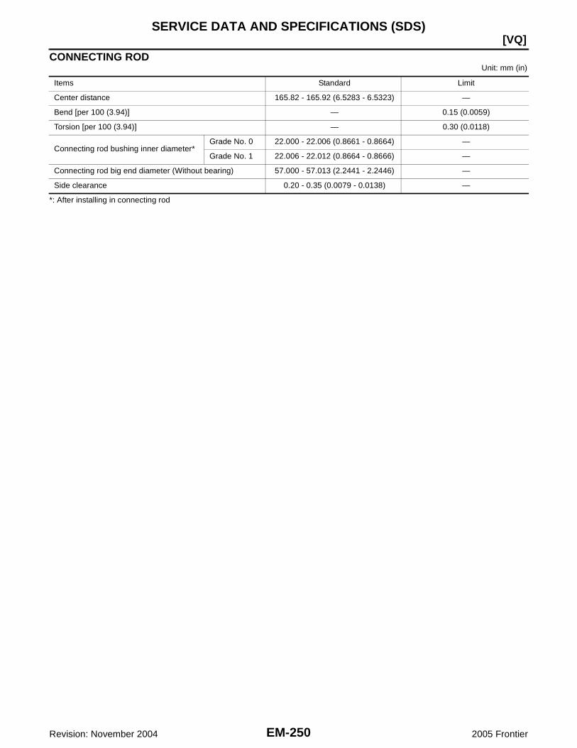
EM-250Revision: November 2004
[VQ]SERVICE DATA AND SPECIFICATIONS (SDS)
2005 Frontier
CONNECTING RODUnit: mm (in)
*: After installing in connecting rod
Items Standard Limit
Center distance 165.82 - 165.92 (6.5283 - 6.5323) —
Bend [per 100 (3.94)] — 0.15 (0.0059)
Torsion [per 100 (3.94)] — 0.30 (0.0118)
Connecting rod bushing inner diameter*Grade No. 0 22.000 - 22.006 (0.8661 - 0.8664) —
Grade No. 1 22.006 - 22.012 (0.8664 - 0.8666) —
Connecting rod big end diameter (Without bearing) 57.000 - 57.013 (2.2441 - 2.2446) —
Side clearance 0.20 - 0.35 (0.0079 - 0.0138) —

SERVICE DATA AND SPECIFICATIONS (SDS)
EM-251
[VQ]
C
D
E
F
G
H
I
J
K
L
M
A
EM
Revision: November 2004 2005 Frontier
CRANKSHAFTUnit: mm (in)
*: Total indicator reading
Main journal diameter. “Dm” grade Standard
Grade No. AGrade No. BGrade No. CGrade No. DGrade No. EGrade No. FGrade No. GGrade No. HGrade No. JGrade No. KGrade No. LGrade No. MGrade No. NGrade No. PGrade No. RGrade No. SGrade No. TGrade No. UGrade No. VGrade No. WGrade No. XGrade No. YGrade No. 4Grade No. 7
69.975 - 69.974 (2.7549 - 2.7549)69.974 - 69.973 (2.7549 - 2.7548)69.973 - 69.972 (2.7548 - 2.7548)69.972 - 69.971 (2.7548 - 2.7548)69.971 - 69.970 (2.7548 - 2.7547)69.970 - 69.969 (2.7547 - 2.7547)69.969 - 69.968 (2.7547 - 2.7546)69.968 - 69.967 (2.7546 - 2.7546)69.967 - 69.966 (2.7546 - 2.7546)69.966 - 69.965 (2.7546 - 2.7545)69.965 - 69.964 (2.7545 - 2.7545)69.964 - 69.963 (2.7545 - 2.7544)69.963 - 69.962 (2.7544 - 2.7544)69.962 - 69.961 (2.7544 - 2.7544)69.961 - 69.960 (2.7544 - 2.7543)69.960 - 69.959 (2.7543 - 2.7543)69.959 - 69.958 (2.7543 - 2.7542)69.958 - 69.957 (2.7542 - 2.7542)69.957 - 69.956 (2.7542 - 2.7542)69.956 - 69.955 (2.7542 - 2.7541)69.955 - 69.954 (2.7541 - 2.7541)69.954 - 69.953 (2.7541 - 2.7540)69.953 - 69.952 (2.7540 - 2.7540)69.952 - 69.951 (2.7540 - 2.7540)
Pin journal diameter. “Dp” grade Standard
Grade No. 0 53.968 - 53.974 (2.1247 - 2.1250)
Grade No. 1 53.962 - 53.968 (2.1245 - 2.1247)
Grade No. 2 53.956 - 53.962 (2.1242 - 2.1245)
Center distance “r” 45.96 - 46.04 (1.8094 - 1.8126)
Taper (Difference between “A” and “B”)Limit
0.002 (0.0001)
Out-of-round (Difference between “X” and “Y”) 0.002 (0.0001)
Crankshaft runout [TIR*]Standard Less than 0.05 (0.002)
Limit 0.10 (0.0039)
Crankshaft end playStandard 0.10 - 0.25 (0.0039 - 0.0098)
Limit 0.30 (0.0118)
SEM645 SBIA0535E

EM-252Revision: November 2004
[VQ]SERVICE DATA AND SPECIFICATIONS (SDS)
2005 Frontier
MAIN BEARING
UndersizeUnit: mm (in)
Main Bearing Oil ClearanceUnit: mm (in)
*: Actual clearance
Grade number UPR/LWR Thickness mm (in) Width mm (in) Identification color Remarks
0 — 2.500 - 2.503 (0.0984 - 0.0985)
19.9 - 20.1(0.783 - 0.791)
Black
Grade is the samefor upper and lowerbearings.
1 — 2.503 - 2.506 (0.0985 - 0.0987) Brown
2 — 2.506 - 2.509 (0.0987 - 0.0988) Green
3 — 2.509 - 2.512 (0.0988 - 0.0989) Yellow
4 — 2.512 - 2.515 (0.0989 - 0.0990) Blue
5 — 2.515 - 2.518 (0.0990 - 0.0991) Pink
6 — 2.518 - 2.521 (0.0991 - 0.0993) Purple
7 — 2.521 - 2.524 (0.0993 - 0.0994) White
01UPR 2.503 - 2.506 (0.0985 - 0.0987) Brown
Grade is differentfor upper and lowerbearings.
LWR 2.500 - 2.503 (0.0984 - 0.0985) Black
12UPR 2.506 - 2.509 (0.0987 - 0.0988) Green
LWR 2.503 - 2.506 (0.0985 - 0.0987) Brown
23UPR 2.509 - 2.512 (0.0988 - 0.0989) Yellow
LWR 2.506 - 2.509 (0.0987 - 0.0988) Green
34UPR 2.512 - 2.515 (0.0989 - 0.0990) Blue
LWR 2.509 - 2.512 (0.0988 - 0.0989) Yellow
45UPR 2.515 - 2.518 (0.0990 - 0.0991) Pink
LWR 2.512 - 2.515 (0.0989 - 0.0990) Blue
56UPR 2.518 - 2.521 (0.0991 - 0.0993) Purple
LWR 2.515 - 2.518 (0.0990 - 0.0991) Pink
67UPR 2.521 - 2.524 (0.0993 - 0.0994) White
LWR 2.518 - 2.521 (0.0991 - 0.0993) Purple
PBIC2969E
Items Thickness Main journal diameter
0.25 (0.0098) 2.633 - 2.641 (0.1037 - 0.1040) Grind so that bearing clearance is the specified value.
Items Standard Limit
Main bearing oil clearance 0.035 - 0.045 (0.0014 - 0.0018)* 0.065 (0.0026)

SERVICE DATA AND SPECIFICATIONS (SDS)
EM-253
[VQ]
C
D
E
F
G
H
I
J
K
L
M
A
EM
Revision: November 2004 2005 Frontier
CONNECTING ROD BEARING
UndersizeUnit: mm (in)
Connecting Rod Bearing Oil ClearanceUnit: mm (in)
*: Actual clearance
Grade number Thickness mm (in) Identification color (mark)
0 1.500 - 1.503 (0.0591 - 0.0592) Black
1 1.503 - 1.506 (0.0592 - 0.0593) Brown
2 1.506 - 1.509 (0.0593 - 0.0594) Green
Items Thickness Crank pin journal diameter
0.25 (0.0098) 1.626 - 1.634 (0.0640 - 0.0643) Grind so that bearing clearance is the specified value.
Items Standard Limit
Connecting rod bearing oil clearance 0.034 - 0.059 (0.0013 - 0.0023)* 0.070 (0.0028)

EM-254Revision: November 2004
[VQ]SERVICE DATA AND SPECIFICATIONS (SDS)
2005 Frontier