bending test
DESCRIPTION
descripcion teorica en ingles del ensayo destructivo de pandeoTRANSCRIPT
Universidad Tecnológica de Altamira.
Name of Investigation: “Bending Test”
Presented by:
Ramírez Trejo Moisés de Jesús.
García Cárdenas Iván Alfredo.
Teacher:
Ing. Francisco Javier Estrada Castillo.
Name of the Subject:
Destructive Testing.
Grade and Group:
IMI-8-A
Industrial Area Maintenance.
Altamira, Tamps.
June, 2015
Introduction.
Method for measuring ductility of certain materials. There are no standardized terms for presenting
the results of bending tests in broad classes of materials; on the other hand, terms associated with
trials of bending to specific material types or forms. For example, materials specifications
sometimes require that a specimen is flexed to a specified inside diameter (ASTM A - 360, steel
products). In ASTM E-190 provides a bending test to check the ductility of welded joints. A
description of the fracture or photographs are used to report the results of the tests of wood.
(ASTM D-1037).
Generally, there are two types of bending tests: 3-point bend and 4-point bend. The materials that
are tested using the flex test method vary from metal, plastic, wood, laminates, particle board, dry
wall, ceramic tile to glass. Bending tests vary greatly based on the product being tested.
There are a variety of industry standards which are mostly based on the sample material under
test. Bending tests generally involve the measurement of ductility of a sample material. Bending
tests may involve taking the sample material to a specific limit and determining the load
measurement and its relationship to a load specification (pass/fail). Or, it may involve bending a
material until the material experiences a break and determining both the load and deflection
required to initiative the break limit.

Understanding Bend Tests
Many welding codes require bend tests as part of the testing required to qualify welders and
welding procedures specifications (WPSs). The concept of a bend test for welds is simple: two
plates are welded together and a flat strap of metal is cut from the welded plates. Next, the flat
strap of a prescribed size is bent into a U-shape, stretching the material on the outer surface of the
"U," while compressing the material on the inside surface.The purpose is to make certain the weld
and the base metal are properly fused, and that the weld metal and the heat affected zone (HAZ)
have appropriate mechanical properties (Figure 1).
Although bend tests appear to be simple, any number of things can cause good welding procedure specifications or good welders to fail. The person responsible for accepting or rejecting test results must understand those factors, and know how to correct for any that are causing inappropriate failure.
Bend specimens have been called "a poor man's tensile test." Although it will not show the quantitative values associated with a tensile test, a bend test will demonstrate both the quality of the weld and its overall ductility. Usually, bend tests are designed so that the outer surface of the specimen is stretched to a ductility level that approximates the minimum percent elongation required in a tensile test. When defects exist in materials strained to these limits, the material tears locally. When tearing exceeds a specific limit, the specimen fails.
Fig.1. In a bend test, a flat strap of metal is bent into a U-shape,stretching the material on the outer surface of the "U," whilecompressing the material on the inside surface.

Direction of rolling
Steel is not fully isotropic, and ductility is sensitive to rolling direction. When steel is
strained parallel to the direction of rolling, the highest values of elongation are obtained.
When it is stretched perpendicular to the rolling direction, ductility is reduced. The poorest
ductility usually is measured in the through-thickness direction.
Qualification test plates can be prepared with the weld groove preparation parallel to the
direction of rolling. The length of the bend specimens extracted from such a test plate will
be perpendicular to the rolling direction (Figure 2). This means when the specimen is bent,
straining is perpendicular to the rolling direction and the transverse ductility affects the test.
Sometimes specimens break near the interface of the weld and base metal, with the
fracture revealing a fibrous, "woody" appearance.Failures like these have nothing to do
with either welder skill or the suitability of the WPS. However, neither will be qualified until
these testing problems are overcome.
Fortunately, the solution is simple — change the orientation of the weld seam so that the weld axisis perpendicular to the rolling direction (Figure 3).
Figure 2: Qualification test plates prepared with the weld groove preparation parallel to the direction of rolling.
Figure 3: Re-orient the weld seam so that the weld axis is perpendicular to the rolling direction.

Bending Terminology.
Here are some diagrams and terms that you may find useful.
• Arc - The degree of bend for the curved portion of an pipe, tube or beam.
• Bevel - A type of end finishing for a pipe, tube or beam.
• Centerline Radius (CR) - Distance from the center of curve to the centerline axis of the pipe,
tube or beam. Abbreviated as CLR.
• Cold Forming - Using cold shaping methods to bend a pipe or other object.
• Degree - An increment of angle to form a bend above the plane of 0 degrees, to which the bend
is formed (i.e. 10, degrees, 45 degrees, 90 degrees, 180 degrees, etc.)
• Extrados - The exterior curve of an arc.
• Easy Way (EZ) - Bending of a rectangular pipe, tube or beam along its shortest dimension of
length.
• Hard Way (HW) - Bending of a rectangular pipe, tube or beam along its thickest dimension of
length.
• I.D. - The Inside diameter of the pipe or tube.
• Intrados - The interior curve of an arc.
• Neutral Axis - The unbent portion of an object (pipe, tube or beam) that is neither compressed or
under tension due to bend.
• O.D. - The Outside diameter of a pipe, tube or beam in inches.Out of Plane - The deviation from
a horizontal plane of rectangular object by a single bend, between its tangent points and the
centerline of the bend.
• Ovality - The distortion of pipe or tube from it's a circular shape caused by bending.

• Material Grade - Manufacturers' specification of material for pipe, tube or beam material, (i.e.
A53B, T304W SS).
• Plain End - Square cuts made to a pipe, tube or beam prior to bending.
• Roll Past - Degree or fraction of degree that a pipe, tube or beam is bent beyond a specified
point.
• Rough Cut - Pipe, tube or beam end cuts that are not required to be straight.
• Square Cut - End cuts to a pipe, tube or beam that are square to the centerline of a bend after
the bending process.
• Tangent - The straight portion of material on either side of arc of a bend.
• Tangent Point - A point where the bend of a pipe, tube or beam begins or ends.
• Taper Bore - A milling or grinding out of the inside diameter of the end of a bend to create a
tapered pipe or tube diameter.
• Wall - The thickness in inches of the outside wall of a pipe or tube.
• Wrinkles - Ribbed or wavy indentations in the inner bend angle of a bend of a pipe, tube or
beam.

Behavior of Materials in Bending.
Many machine and structural parts are often subjected to bending and shear stresses. In most
cases, it is highly desirable to test such parts under the conditions that simulate the actual service
loading.
The static bending and shear properties of materials are not of the same universal interest as the
static tension and compression properties. This is because such properties might be determined
directly, or at least some insight may be gained to these properties from tensile test data (for
instance.
The preparation and adequate testing of tension test specimens might be difficult, hence simpler
shear and bending tests are often employed.
When a member of a structure or machine is subjected to bending load, it acts as a beam which
has a primary function of resisting this loading.
In bending, both tensile and compressive stresses are induced over a cross section of the beam.
Thereby, bending tests are less severe than tensile tests, but more severe than compressive tests.
In fact, a bending test does not provide extra information on mechanical behaviour of a material
unless bending causes special failure. Its value is defined as a direct means of evaluating the
behaviour of beams under loading or as a simple means to determine the strength and ductility.
Since the loads required to cause failure relatively small and easily applied, bending tests can be
made with simple and cheap apparatus. Moreover, test specimens are simple and easy to prepare,
also gripping problems are eliminated and deflection data are more easily obtained.
There are two common types of bending tests:
1. 3-point bending (Fig. 1a): applying a concentrated load at the span centre.
2. 4-
point
bending (Fig. 1b): applying half-loads equally distant from supports.
3-point bending method is often used due to its simplicity.

However, the 4-point bending (pure-bending)
method characterises the material properties
better due to constant bending moment which
occurs between inner load points.

3- Point Bending. 4- Point Bending.
Bending tests are intended for brittle materials when the scope of test is to determine the strength
of material.
The bending strength of a material is defined by various titles such as: flexural strength, cross-
breaking strength, transverse strength, modulus of rupture, and coefficient of bending strength.
To determine the bending strength, the beam must be so proportioned that it will not fail in shear or
by lateral deflection before reaching its ultimate flexural strength. Usually, long specimens with
higher length to depth ratio (L/h > 10) are recommended. Likewise, a shorter beam (L/h < 6) is
intended for shear failure testing in bending.
Hence, for a rectangular part in a 3-point bending test,
bending strength is the highest stress at the moment
of rupture:
Bending tests are notably employed for cast iron (based on ASTM A48), concrete, wood and
certain plastics (according to ASTM D790-66, BS 2782 and DIN 53452) using circular or
rectangular specimens.

The
flexural strength of brittle materials obtained from bending tests would be higher than that
determined from tensile tests. As failure is approached, the neutral axis shifts toward the
compression face, and thus tends to strengthen the beam.
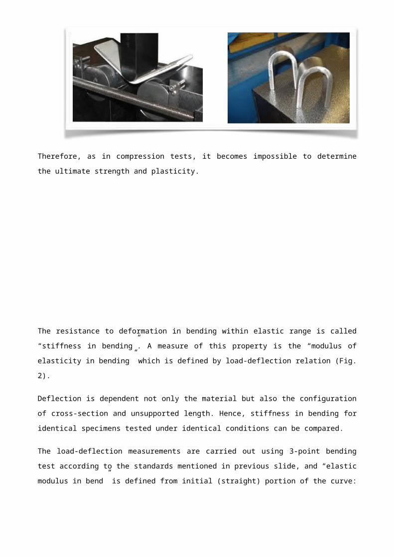
Bending tests cannot be employed to determine the flexural strenght ductile materials since
specimens cannot be fully bent without rupture.
Therefore, as in compression tests, it becomes impossible to determine the ultimate strength and
plasticity.

The resistance to deformation in bending within elastic range is called “stiffness in bending”. A
measure of this property is the “modulus of elasticity in bending” which is defined by load-deflection
relation (Fig. 2).
Deflection is dependent not only the material but also the configuration of cross-section and
unsupported length. Hence, stiffness in bending for identical specimens tested under identical
conditions can be compared.
The load-deflection measurements are carried out using 3-point bending test according to the
standards mentioned in previous slide, and “elastic modulus in bend” is defined from initial
(straight) portion of the curve:
For ductile materials, cold-bend and folding tests are used to determine whether the material can
be bent sharply without cracking and serves as a simple acceptance test with respect to this form
of ductility.
The scope of such tests is to check ductility for particular type of service or to detect loss of ductility
under certain types of treatment.
The test consists in sharply bending a bar
through a large angle and noting if cracking
occurs on the outer surface. The aim is to
determine the angle (θ) at which cracking starts

(Fig. 3a). If no cracks produced while specimen is bent around the pin, testing is continued by
compressing the specimen on itself between the compression platens referred as “folding” (Fig.
3b).
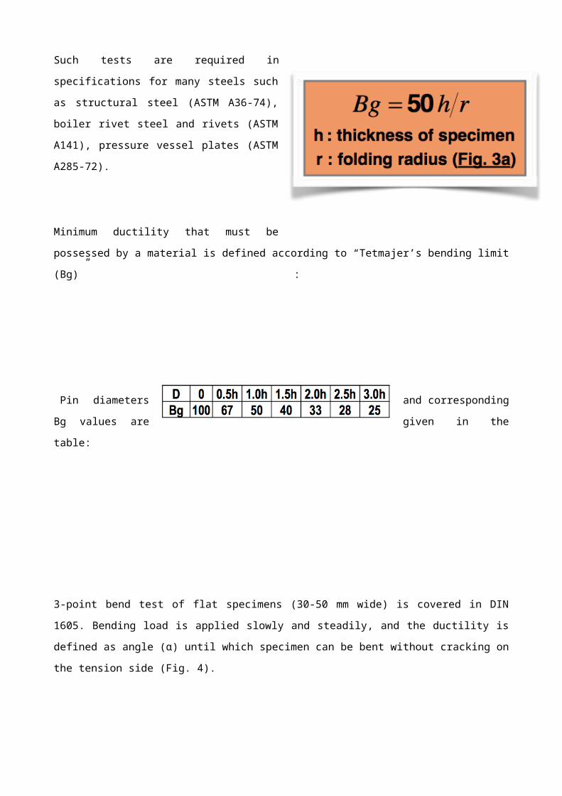
Such tests are required in specifications for
many steels such as structural steel (ASTM
A36-74), boiler rivet steel and rivets (ASTM
A141), pressure vessel plates (ASTM A285-72).
Minimum ductility that must be possessed by a
material is defined according to “Tetmajer’s
bending limit (Bg)” :
Pin diameters and corresponding Bg
values are given in the table:
3-point bend test of flat specimens (30-50 mm wide) is covered in DIN 1605. Bending load is
applied slowly and steadily, and the ductility is defined as angle (α) until which specimen can be
bent without cracking on the tension side (Fig. 4).
The inner
distance
between
supports
should be
D+3h, and the outer
supports must have
a radius of 25 mm
(for h<12 mm) or 50
mm (for h>12 mm).
1.- Notched-Bar Test: It is used to specify the resistance of a material against shock, and its ability
to withstand stress concentration.
Similar to tension test, the work done in bending the test piece through about a right angle (using
Monsanto Tensometer in Fig. 5) can also be employed as “toughness index number”, which is
expressed as product of force applied by the nose and the distance through which it moves.

2.- Weld Test: Similar in concept to 3-point bending test, weld test is carried out by subjecting a
butt-welded specimen to transverse loading in a fixture. The load is applied slowly and steadily
until either cracks are produced on the tension side or the specimen is bent to extreme limit in the
fixture (in such case, specimen is removed and testing is continued as in folding test). Fig. 6a and
6b show the free-bend test fixtures for testing the ductility of welds according to ASTM E16-64 and
DIN 50121, respectively.
3.- Fiber-Strain Measurements: made in connection with
weld tests.
Tension side of specimen is marked over a distance and
“percent elongation” of outer fiber is specified through the use of flexible tape. Hence, original (L0)
and final length (Lf) are used to calculate ductility (R):
4.- Hot-Bend Test: made with specimens heated to “red-hot” temperature to determine suitability of
material to hot-working.
This test is also employed for welded joints to test “blue brittleness”.
Plain carbon steels experience discontinuous yielding within 230-370 °C (known as “blue brittle
region”) as steel heated in this range shows a lower tensile ductility and higher notch sensitivity.

5.- Quenched-Bend Test: used in connection with plates used for boilers.
The specimen is heated to 650 °C and held at this temp. about half an hour. It is then quenched in
warm water around 28 °C and subjected to bend test. The aim is to detect traces of nitrogen
present in the metal, indicated by fracture.
Aplications of Bending Test.
The bending test is used to determine the resistance of a material by the application of force to the
point of maximum tension and see how he reacts under pressure. Normally, the bend test
measured ductility, the ability of a material to change shape under pressure and maintain that
shape. In some cases, the bending test can determine the tensile strength. When using bending
test for this purpose, testers examine that part of the material breaks first to see what kind of force
has the material. It also allows them to know what kind of pressure is capable of enduring.
Ductility describes to what extent a material, usually metal, can stretch and maintain your new
shape. Steel, for example, is very ductile. If pressure is applied it extends into a new form, which
will be maintained even when the pressure is removed. This feature is known as ductility and is a
desirable feature for metals and other building materials.
To determine how ductile is a material used in laboratories the bending tests. Force in ascending
amounts applies to a piece of material at a specific angle and for a specific amount of time. The

material is then twisted a certain diameter due to the use of force. Once bending test is finished,
the material is examined to see until it is able to maintain its shape once removed the pressure,
and whether or not the material is cracked when pressure is applied.
This test can also determine the tensile strength. The test may be used with materials more fragile
to test its resistance. These fragile materials, those who cannot stand well in a normal test for
tensile strength, are used in a bending test. This essay applies in the same way as usual, bending
the material while the force is applied, and then the results are examined. If the material has cracks
in the bent part, it shows that material supports better compression than tension.
Welding is an area where the bend test is used very often. A double guide test is used to
determine that strong is a weld after it's been built. A special test machine is used to perform
guided bending test. The material must be able to bend to a specific angle, such as 180 degrees,
for example, without any kind of cracks that appreciate. If this happens, welding has passed the
test and the material can be used without problems in your destination, either construction, naval
or steel industry.
The bending stress is a form of stress that occurs when loads are applied perpendicular to an
object, making it necessary to divert the load. The degree of curvature that an object is able to
tolerate until there is a permanent deformation varies, depending on the materials of construction,
size, and other variables. Test products to determine their tolerances to the bending stress is an
important part of the safety tests, especially for things such as elements that are used in
construction, where deformation under tension can lead to structural collapses and fatal
consequences.
Many types of objects are tested with this type of procedure, a simple example being the cabinets.
Cabinets typically have one or more grab bars at each end. When these bars are loaded with
clothes, shoes and other belongings, castings can deviate under the weight of the load. A solid
hanging bar will recover its position when the load is removed.
Finally, the burden can become so high that the rod is permanently bent or appear cracks in
pressure as a result of the bending stress. Bending tests help determine how much load and what
types of materials are suitable for use in the manufacture of products such as cabinets and see
daily in our daily lives.
Scope
These test methods cover bend testing for ductility of materials. Included in the procedures are four
conditions of constraint on the bent portion of the specimen; a guided-bend test using a mandrel or

plunger of defined dimensions to force the mid-length of the specimen between two supports
separated by a defined space; a semi-guided bend test in which the specimen is bent, while in
contact with a mandrel, through a specified angle or to a specified inside radius (r) of curvature,
measured while under the bending force; a free-bend test in which the ends of the specimen are
brought toward each other, but in which no transverse force is applied to the bend itself and there
is no contact of the concave inside surface of the bend with other material; a bend and flatten test,
in which a transverse force is applied to the bend such that the legs make contact with each other
over the length of the specimen.
After bending, the convex surface of the bend is examined for evidence of a crack or surface
irregularities. If the specimen fractures, the material has failed the test. When complete fracture
does not occur, the criterion for failure is the number and size of cracks or surface irregularities
visible to the unaided eye occurring on the convex surface of the specimen after bending, as
specified by the product standard. Any cracks within one thickness of the edge of the specimen are
not considered a bend test failure. Cracks occurring in the corners of the bent portion shall not be
considered significant unless they exceed the size specified for corner cracks in the product
standard.
The values stated in SI units are to be regarded as standard. Inch-pound values given in
parentheses were used in establishing test parameters and are for information only.
This standard does not purport to address all of the safety concerns, if any, associated with its use.
It is the responsibility of the user of this standard to establish appropriate safety and health
practices and determine the applicability of regulatory limitations prior to use.
Regulations of the Bending Test.
The standards ASTM E290, ISO 7438 are required and JIS Z2248 describes the requirements for
Flex testing to see the ductility of metallic materials. The bending test helps to provide a visual
indication of the ductility of the material. The guided test method requires load is applied at the
center point of the sample while it is supported at the ends. The specimen is folded up to a default
angle or until it is fractured. The convex side of the sample is inspected visually for cracks or
defects in, and the failure is determined by the size of the cracks and imperfections that are
permitted by the specifications of the material.
For this test, a team in the series SATEC KN, DX, or HDX model with a Flex W-6810 accessory is
recommended. This accessory allows you to adjust the distance between supports and is supplied
with various sizes of chucks of load to accommodate different thicknesses specimens. Load
brackets have some reinforcements to provide greater rigidity during charging. DX or HDX are

models that have a double test area, so Flex is done at the bottom where the compressions are
performed and is always the top free to make traction.
Trial software packages include Flex applications that allow a simple configuration of the assay.
The software generates the load curves in real time and can determine the end of the test
automatically when there is a break or when it comes to the proper angle. Our advanced control
electronics offers the best response, precision data and resolution. In addition, the system supports
the interconnection of external signs of control or measurement.
Bending test of wood (ASTM-D143, ISO 3133, 310).
The wood is usually used as an engineering material in construction and in the furniture industry.
With its wide range of physical and mechanical properties, you can choose wood of different
species of trees to adapt to the specific requirements of an application.
The resistance of the wood is influenced by factors such as the types of loading, direction and
duration of load, temperature and humidity. Standards such as ASTM D143, define the test
methods for determining the mechanical properties, including resistance to bending, tensile
strength and resistance to shear of wood. This allows engineers to choose which best fits the
needs.
Different standards may have slightly different requirements and a challenge is to try to comply
with different regulations. For example, ASTM-D143, claims that the lower support brackets of the
bending attachment to three points should have bearings and that the load should be applied in the
Centre of the sample by a rigid upper block. However, ISO 3133 says that the support and
attachment of the load application must be a specified diameter rollers.
To ensure arising the first break of the sample of traction or compression and not of the shear
stress, many wood bending test standards require that the attachment has a relationship width-
profundity minimum of 14. A typical configuration of the test would be to use either our 3300 or
5500 series electromechanical machine configured with beam series 2820 base or a fixture three
points for this essay. In addition, a falling weight deflectometer is available to measure deviations
from bending to the axial axis, as specified by the standard ASTM-D143.
The 2820 bending of wood accessories series is designed following common international rules for
bending tests on a range of wood products. The modular design of this series of accessories
provides maximum flexibility, offering a range of optional plates and four-point conversion kits, in
order to meet different standards. This allows that accessories can be configured to meet a wide
range of standards at the same time that share as many common parts as possible.

References.
1. Willems Nicholas, Easley John T, Stanley T. Rolfe. Resistencia de materiales. 1984, McGraw
Hill.
2. Hibbeler R. C. Mecánica de materiales. Quinta Reimpresión, 2004, CECSA.
3. Craig Roy R, Jr. Mecánica de materiales. Primera Edición en Español, 2002, CECSA.
4. Rossmanith H.P. Fracture mechanics and materials testing: forgotten pioneers of the early 20th
century. ©1999, Blackwell Science Ltd. Fatigue Frac. Engng Mater Struct 22, 781-797.
5. Comentarios Históricos sobre la teoría de flexion. ©1983, Journal of structural engineering, Vol.
109.
6. http://www.dyna.mess.de/es/produkte/maschinen.html. Sistemas de ensayos.
7. http://www.fceia.unr.edu.ar/ensayosnormalizados/. Maquinas de laboratorio de ensaye.
8. http://www.imnc.org.mx/laboratoriosdeensayoydecalibracion_c_111.html. Instituto Mexicano de
Normalización y Certificación A.C.
9. http://dimei.fi-b.unam.mx/udiatem/instalaciones.htm. Departamento de Materiales y
Manufactura, Unidad de Investigación y Asistencia técnica en Materiales (UDIATEM), laboratorio
de pruebas mecánicas.
10. Laboratorio de Ensaye de Materiales, Departamento de Ingeniería Civil y Topografía, (CUCEI)
UDG.
11. http://www.gunt.de/static/s7_3.php?p1=&p2=&pN. Mecánica Aplicada y Ensayo de Materiales.
12. http://www.tq.com/teachequip_products.asp?choice=1&menu=1. Materials Testing and
Properties.
13. Seely Fred B, Smith James O. Resistencia de materiales. 1974, UTEHA.
14. Monroe Gere James, Timoshenko Stephen. Resistencia de materiales. 2002, Thomson
Learning Ibero.
15. Hibbeler Russel C. Mecánica vectorial para ingenieros. Estática. Décima Edición, 2004,
Pearson Educación.