bending of carbon nanotubes ropes
TRANSCRIPT

BENDING OF CARBON NANOTUBES ROPES
Veturia Chiroiu ([email protected])Institute of Solid Mechanics of Romanian Academy
Petre P. Teodorescu ([email protected])
University of Bucharest
Ligia Munteanu (ligia_munteanu@ hotmail.comInstitute of Solid Mechanics of Romanian Academy
Viorel-Puiu Paun ([email protected])University Politehnica from Bucharest

2
The key concept of the space elevator appeared in 1895 when russian scientist Konstantin Tsiolkovsky was inspired by the Eiffel Tower in Paris to consider a tower that reached all the way into space, built from the ground up to an altitude of 35790 km above sea level.
After discovery of carbon nanotubes in the 1991, engineers realized that the high strength of these materials might make the concept of an orbital skyhook feasible, and plan for an elevator to turning the concept into a reality
(see Science @ NASA, Audacious&Qutrageous:SpaceElevators, Sept. 2000 )

3
Carbon nanotubes were
discovered in 1991 by the
japanese physicist. Iijima Sumio,
(born May 2, 1939).
Besides their small size, the carbon nanotubes are half as dense as aluminum, have tensile strengths 100 times that of steel alloys, have current carrying capacities 1000 times that of copper, and transmit heat twice as well as pure diamond.
Iijima S 1991, Helical microtubules of graphitic carbon, Nature (London) 354, 56–58.Iijima S 1993, Single-shell carbon nanotubes of 1-nm diameter,Nature (London) 363, 603–605.

4
Definition of roll-up vector r as linear combination of base vectors a and br = na+mb

5
~ 0.0129.60.25
KevlarTEExperimental observationTTheoretical prediction
~ 0.01~3.5~0.15Kevlar
~ 0.04~ 0.65 - 1~ 0.2Stainless Steel
0.5 - 2Edepending of diameter
1500.8 - 0.9EMultiple walls carbon nanotube
0.2 – 1.4Edepending of diameter
95T0.92TChiral SWNT
0.3 – 1.4Edepending of diameter
94.5T0.94TZigzag SWNT
0.4 – 1.4Edepending of diameter
126.2T0.94TArmchair SWNT
0.2 - 2Edepending of diameter
13 - 53E~ 1 - 5Edepending of diameter
Single wall carbon nanotube (SWNT)
Bending modulus [TPa]
Tensile Strength [GPa]
Young’s modulus [TPa]Material
(see D.Srivastava, C. Wei: Nanomechanics of carbon nanotubes and composites, Appl Mech Rev vol56, no 2, March 2003)

6
In this paper we consider only the single-walled carbon nanotubes.
While multi-walled nanotubes are easier to produce and have similar tensile strengths, there is a concern that the interior tubes would not be sufficiently coupled to the outer tubes to help hold the tension.
If the nanotubes are long enough, even weak Van derWaals forces will be sufficient to keep them from slipping, and the full strength of individual nanotubes could be realized macroscopically by spinning them into a yarn.

7
Carbon nanotubes have lengths of tens to hundreds of microns, far short of any macroscopic requirement. The key is to get the carbon nanotubes into a composite : ropes of carbon nanotube composites
In polymeric composites, carbon nanotubes can reduce weight by a factor of 5-10, while increasing the strength by a factor of 5-10 compared to a conventional carbon fiber matrix , with ultra-strong individual fibers roughly 10 microns in diameter and lengths of many meters to kilometers, with uniform alignment of the nanotubes in the matrix, efficient stress transfer from the matrix to the nanotube, and attaining high nanotube loadings.

8B.C.Edwards, The space elevator NIAC Phase II, Final report, 2005.

9
In this paper, the rope is composed from 6 subropes, each subrope being composed from 7 groups of single wall carbon nanotubes. Each group has 25 carbon nanotubes with two different radii (zigzag and armchair 6.26A, h = 0.617A and 16.33A, h = 0.998A), and the core group consists of 49 chiral carbon nanotube with the same radius (3.22A and h = 0.6A), into a polymeric matrix.

10
The bending of this carbon nanotube rope is describedby a coupled continuum –atomistic method.
The continuum method is setup in the light of Cosseratelasticity, which admits degrees of freedom not present in classical elasticity: the rotation of points in the material, and a couple per unit area (couple stresses).
The atomistic method is used in the regions where the continuum method is no longer valid.

11The generic form of the coupling atomistic-continuum regions.

12
The classical mechanics fail in describing the mechanical behaviorof the carbon nanotube ropes under deformation. The rope is modeled as an elastic chiral material (noncentrosymmetricmaterial) which is isotropic with respect to coordinate rotations but not with respect to inversions.
So these materials have a qualitatively different behavior in comparison with isotropic solids.Chiral effects cannot be expressed within classical elasticity since the modulus tensor, which is fourth rank, is unchanged under an inversion
4
dd d dd d d d
( 1) ( 1) ( 1) ( 1) ( 1)
= =
= − − − − = − =
pm n oijkl mnop
i j k l
im jn ok pl mnop ijkl ijkl
xx x xC Cx x x x
C C Cδ δ δ δ

13
Constitutive equations for an isotropic centrosymmetric Cosserat solid
(1)
(2)
is the stress tensor , is the couple stress tensor (moment per unit area),
is the small strain tensor (macrostrain vector),
is the displacement vector, the permutation symbol. the microrotation vector
the macrorotation vector
(2 ) ( )kl rr kl kl klm m me e rσ λ δ μ κ κε ϕ= + + + −
, , ,kl r r kl k l l km αϕ δ βϕ γϕ= + +
klσ klm
. ,1 ( )2kl k l l ke u u= +
u klmεkϕ
,12k klm m lr uε=kr
Lame elastic constants Cosserat rotation modulus
Cosserat rotation gradient moduli
λ μκ
, ,α β γ

14
1 , 2 , 3 ,
(2 ) ( ),
kl rr kl kl klm m m
r r kl k l l k
e e rC C Cσ λ δ μ κ κε ϕϕ δ ϕ ϕ= + + + − +
+ +
, , ,
1 2 3 3 2( ) ( ) ( ),kl r r kl k l l k
rr kl kl klm m m
mC e C C e C C rαϕ δ βϕ γϕ
δ ε ϕ= + + +
+ + + + − −
The constitutive equations for a anisotropic noncentrosymmetric Cosserat solid can be written in the form
1 2 3, ,C C C positive or negative chiralelastic constants

15
1 1
2 3
( sin sin cos cos cos )(cos sin sin cos cos ) sin cos ,
d ee e
= − ψ ϕ+ ψ ϕ θ ++ ψ ϕ+ ψ ϕ θ − θ ϕ
2 1
2 3
( sin cos cos sin cos )(cos cos sin sin cos ) sin sin ,
d ee e
= − ψ ϕ− ψ ϕ θ ++ ψ ϕ− ψ ϕ θ + θ ϕ
3 1 2 3sin cos sin sin cos .d e e e= θ ψ + θ ψ + θ
The Z-axis coincides with the central axis.
We take s to be the coordinate along the central line of the natural state. The orthonormal basis of the Lagrange coordinate system is denoted byand the orthonormal basis of the Euler coordinate system by
. The basis d is related to e by the Euler angles and and . These angles determine the orientation of the Euler axes relative to the Lagrange axes
,θ ψ ϕ
1 2 3( , , )e e e
1 2 3( , , )d d d

16
The motion of the rope is described by three vector functions
× ∋ →
→ ∈ 31 2
( , )( , ), ( , ), ( , ) .
R R s tr s t d s t d s t E
The material sections of the rod are identified by the coordinate s. The position vector can be interpreted as the image of the central axis in the Euler configuration.The functions , can be interpreted as defining the orientation of the material section s in the Euler configuration. The function
represents the unit tangential vector along the rope.
( , )r s t
1( , )d s t 2 ( , )d s t
= ×3 1 2( , ) ( , ) ( , )d s t d s t d s t

17
1 sin sin cosu ′ ′= θ ϕ−ψ θ ϕ
2 cos sin sinu ′ ′= θ ϕ+ψ θ ϕ
3 cosu ′ ′= ϕ +ψ θThese functions measure the bending and torsion of the rope. The first two represent the components of the curvature of the central line k corresponding to the planes yz and xz.
The last is the torsion
2 2 2 2 2 21 2 sinu u ′ ′κ = + = θ + ψ θ
3 cosu ′ ′= τ = ϕ +ψ θ
ττττ

18
2 2 2 2 22
32 2 20
1 2(1 )
⎧ ⎫− τ −′ = − + λ − γ⎨ ⎬−⎩ ⎭
u q u pu uK p u
cosu = θ
21 ( ),2
u f u′ =
Weierstrass equation with a polynomial of third order
220
2 1( ) ( 1)
pK
κ=
α +β + γ −2
2 20
13( ) ( 1)
qK
κ=
α +β + γ −
22 1 2 30
( )( )( 2 )
C C CK + +=
α +β+ γ λ + μ + κ
22 2 3 3( )cn [ ( ), ],= − − α ξ − ξu u u u w m (1)
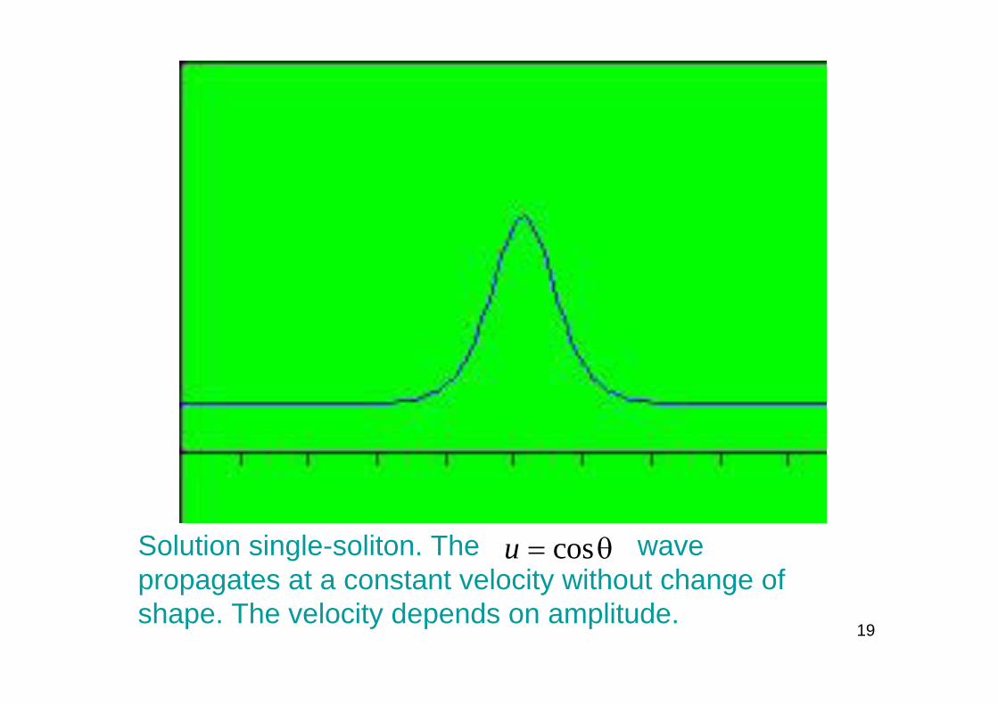
19
Solution single-soliton. The wave propagates at a constant velocity without change of shape. The velocity depends on amplitude.
cosu = θ

20
The general solution for can be written as a nonlinear superposition of single solitons. Here is the superposition of 2 single solitons propagating in same direction (solution 2-solitons). A larger soliton travels with a high velocity so that it overtakes the smaller one and after collision they reappear without changing their form identity.
cosu = θ
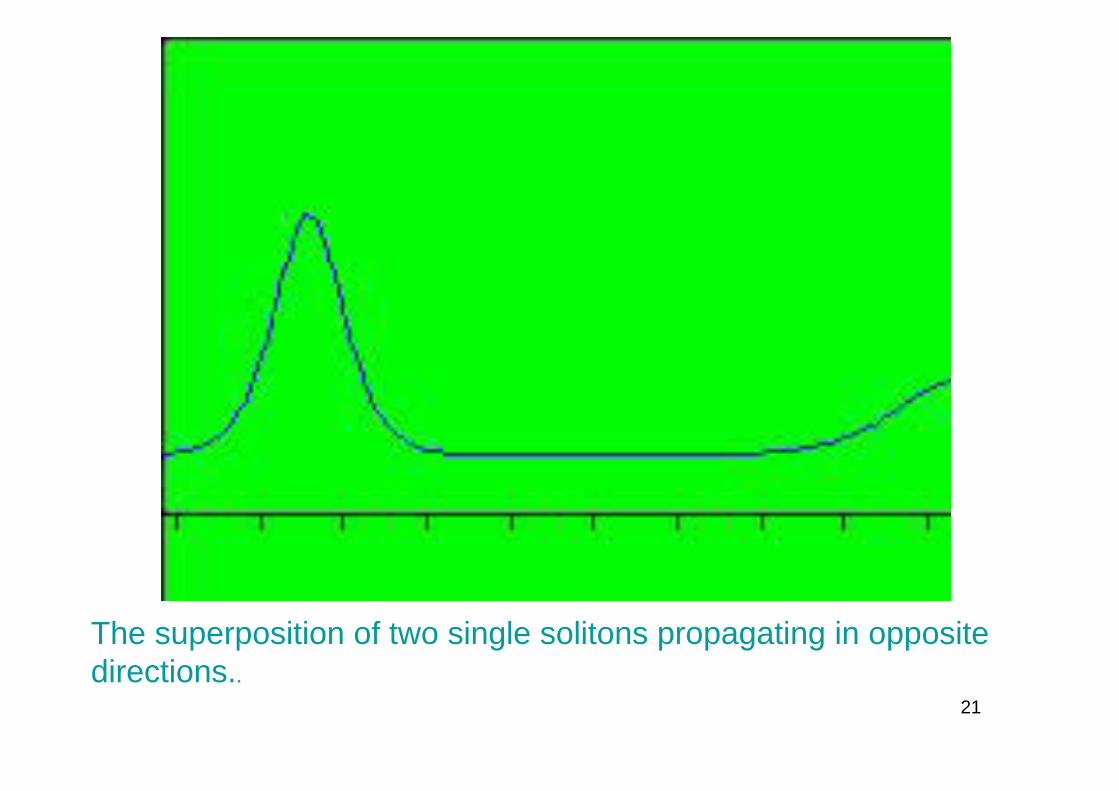
21
The superposition of two single solitons propagating in opposite directions..

22
Animation of Alex Kasman (2001) by gratitude of the author (by Monica Soare) the Rensselaer Polytechnic Institute, Computational Nanomechanics Lab., Troy, New York (2004) – representing the nonlinear superpositions of solitons.
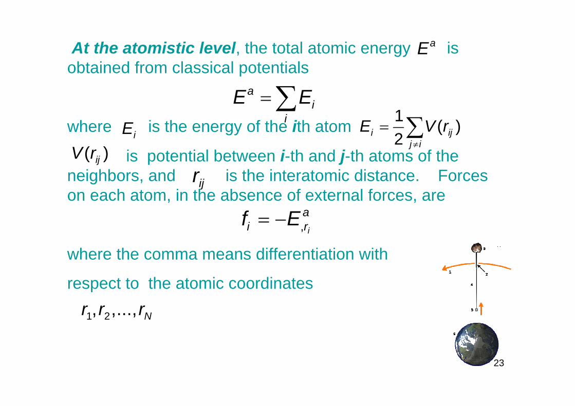
23
At the atomistic level, the total atomic energy is obtained from classical potentials
where is the energy of the ith atom
is potential between i-th and j-th atoms of the neighbors, and is the interatomic distance. Forces on each atom, in the absence of external forces, are
where the comma means differentiation with
respect to the atomic coordinates
aE
=∑ai
iE E
≠
= ∑1 ( )2i ij
j iE V r
iE( )ijV r
ijr
= − , i
ai rf E
1 2, ,..., Nr r r

24
The van der Waals force between atom i and j can be expressed by the Lennard-Jones potential as
⎛ ⎞σ σ= ε −⎜ ⎟⎜ ⎟
⎝ ⎠
12 6
12 6( ) 4ijij ij
V rr r
194.7483 10 Nm−ε = ⋅
σ = 3.407
The term describes repulsion and the term describes attraction.
The force function is the negative of the gradient of the above potential:
The atomic simulations for carbon nanotubes armchair, zigzag and chiral, were performed by the courtesy of Monica Soare at the Rensselaer Polytechnic Institute, Computational Nanomechanics Lab., Troy, New York (2004) and Calin Chiroiu at the Politecnico diTorino, Structural Engineering dept. (2005) .
depth of the potential well
finite distance at which the interparticle potential is zero
121r
⎛ ⎞⎜ ⎟⎝ ⎠
61r
⎛ ⎞⎜ ⎟⎝ ⎠
d ˆ( ) ( ) ( )d
= −∇ = −F r V r V r rr

25
The comparisons of nonlinear chiral theory, the atomistic simulations and experimental results
Bethune DS, Kiang CH, Devries MS, Gorman G, Savoy R, Vazquez J, and Beyers R (1993), Cobalt-catalyzed growth of carbon nanotubes with single-atomic-layerwalls, Nature (London) 363, 605–607. Saito R, Dresselhaus G, Dresselhaus MS (1998), Physical Properties of Carbon Nanotubes, Imperial College Press, London, 361, 201-234.
yields:
Neither the nonlinear theory, either the atomistic approach do not succeed to describe very well the realistic behavior of carbon nanotubes deformation at bending and torsion. The nonlinear theory gives closer results in comparison with the experimental results only for torsion. The atomistic theory gives closer results in comparison with the experimental results only for bending.

26
In the case of bending, when the external bending moment increases, the axial compression in the tube increases too, and when the stress reaches a critical value, the tube will locally buckle. The nonlinear theory is valid up to the point of local buckling at ϑ = o25.58
The definition of the bending angle.

27
The gray region is discretized into 1024 nodal positions.
The pad region is used to relate the atomic numerical solutions to solitonic continuum solutions rewritten as a weighted superposition of exact solutions.
We use the Sinclair’s analytical treatment of the continuum region of a weighted superposition of elementary solitonsolutions that allowed the boundary conditions to be modified during the energy minimization of the atomistic region. The parameters are determined by means of a genetic algorithm, from an objective function.

28
For , the coupled theory put into evidence a solitonic mechanism of deformation. The pattern of the deformation resembles a mechanism similar to that of a macrotube, but in the nanotube case, this mechanism is described by means of solitons.
A portion of the rope flattens and forms a domain that rotate about a central hinge line. The remaining part of the rope remains circular although it flattens and decreases its curvature. Once the solitonic mechanism starts, the rope becomes a mechanical mechanism and the formulas in the continuum theory is no longer valid.
ϑ > o25.58

29
The solitonic mechanism of deformation it is characterized by :
1.The van der Waals force is the interaction between the opposite walls of the rope when they approach each other. This force depends on the distance between them. For large distances, the van der Waals force is attractive, but when the separation between the atoms is below the equilibrium distance of 3.42 Å, it becomes strongly repulsive.
2. With the increase in the bending angle,the the opposite walls get closer to each other, and at a certain stage, the distance between them reaches the equilibrium distance.
ϑ
30
3. Upon additional bending, this distance remains unchanged because there are no extra loads applied on the walls to prevail over the repulsive van der Waalsforces.
4. Upon complete unloading from angles below 109-110°the rope completely elastically recovers. At a very large bending angle of 118-120°, atomic bonds break and the deformation becomes irreversible.
5. The bending modulus is estimated to be 1.6TPa.

31
Bending nanotube zigzag (9,0) radius 6.26 A, thichness 0.617 A

32
Single wall nanotube armchair (5,5) radius 6.26 A, thickness 0.677 A.

33
Single wall nanotube chiral (10,5) radius 3.22 A, thickness 0.6 A.

34
Nanotube zigzag (9,0) r =16.33A, thichness 0.998A

35
Nanotube armchair (5,5) radius 16.33A, h = 0.998A
36
Acknowledgment.This work reported in this paper is sponsored by the CEEX (MEdC-UEFISCSU) Post doctoral grant nr. 1531/2006, code 1, and this support is gratefully acknowledged.