bending instability of electrically charged liquid jets of polymer … · 2015-11-13 · bending...
TRANSCRIPT

JOURNAL OF APPLIED PHYSICS VOLUME 87, NUMBER 9 1 MAY 2000
Bending instability of electrically charged liquid jets of polymer solutionsin electrospinning
Darrell H. Renekera)
Department of Polymer Science, The University of Akron, Akron, Ohio 44325-3909
Alexander L. YarinTechnion-Israel Institute of Technology, Haifa 32000, Israel
Hao Fong and Sureeporn KoombhongseDepartment of Polymer Science, The University of Akron, Akron, Ohio 44325-3909
~Received 20 September 1999; accepted for publication 25 January 2000!
Nanofibers of polymers were electrospun by creating an electrically charged jet of polymer solutionat a pendent droplet. After the jet flowed away from the droplet in a nearly straight line, it bent intoa complex path and other changes in shape occurred, during which electrical forces stretched andthinned it by very large ratios. After the solvent evaporated, birefringent nanofibers were left. In thisarticle the reasons for the instability are analyzed and explained using a mathematical model. Therheological complexity of the polymer solution is included, which allows consideration ofviscoelastic jets. It is shown that the longitudinal stress caused by the external electric field actingon the charge carried by the jet stabilized the straight jet for some distance. Then a lateralperturbation grew in response to the repulsive forces between adjacent elements of charge carried bythe jet. The motion of segments of the jet grew rapidly into an electrically driven bending instability.The three-dimensional paths of continuous jets were calculated, both in the nearly straight regionwhere the instability grew slowly and in the region where the bending dominated the path of the jet.The mathematical model provides a reasonable representation of the experimental data, particularlyof the jet paths determined from high speed videographic observations. ©2000 American Instituteof Physics.@S0021-8979~00!03609-4#
iveng
arg
dei
nte
oloasrbanca
e
pina
f fioin
e-nd-tedets.
ic
ndere
tede-
firstandarhe-
-oningby
as
d to
I. INTRODUCTION
Electrospinning is a straightforward and cost effectmethod to produce novel fibers with diameters in the raof from less than 3 nm to over 1mm, which overlaps con-temporary textile fiber technology. Polymer nanofibersbeing used, or finding uses, in filtration, protective clothinbiomedical applications including wound dressings, druglivery systems, the design of solar sails, light sails, and mrors for use in space, the application of pesticides to plaas structural elements in artificial organs, and in reinforccomposites. Ceramic or carbon nanofibers made from pmeric precursors make it possible to expand the list of psible uses for nanofibers. The electrospinning process eincorporates particles of materials such as pigments, cablack particles, and many others into the nanofibers thatproduced. Flexible fibers are needed on a scale commerate with micro- or nanoelectrical, mechanical and optisystems. The use of Coulomb forces to fabricate polymobjects may lead to ways to make such fibersin situ for suchdevices.
Observations and a theoretical model of the electrosning process are presented in this article. The theorycounts for the nonlinear effects that are characteristic onite perturbations, as well as for the rheological behaviorviscoelastic liquids. The general reason for the bending
a!Electronic mail: [email protected]
4530021-8979/2000/87(9)/4531/17/$17.00
Downloaded 19 Sep 2002 to 129.219.27.131. Redistribution subject to A
e
e,-
r-s,dy-s-ilyonresu-lr
-c--f-
stability in electrospinning is discussed. The thredimensional equations describing the dynamics of the being of electrospun jets are derived and the calculabehavior is compared with experimental observations of j
A. History and patents
Interest in the behavior of thin liquid jets in electrfields dates back to the work of Rayleigh.1 Later Zeleny2
studied liquid jets in strong electric fields. Theoretical aexperimental activities in this area in the last 30 years wrevitalized by several important contributions by Taylor.3–6
He produced useful experimental evidence, and calculathe conical shape of the protrusion from which a jet somtimes leaves the surface of a liquid. Taylor also made theattempt to calculate the growth rates of both varicosebending perturbations of electrified liquid jets in the lineapproximation when the perturbations are small. In his toretical analysis, only inviscid fluids were considered.
The bending instability of thin, highly viscous jets moving in air, with no electrical forces, is a kindred phenomento that treated in the present work. The theory of the bendinstability of uncharged jets was developed and describedYarin and co-workers.7–10
Electrified jets of polymer solutions were investigatedroutes to the manufacture of polymer nanofibers.11–15 Since1934, when a U.S. patent on electrospinning was issueFormhals,16 over 30 U.S. patents have been issued.
1 © 2000 American Institute of Physics
IP license or copyright, see http://ojps.aip.org/japo/japcr.jsp

oaic
vhihhperinu
b
thsmn
nsthrngai-
letivgs
eln
arceeu
erTre
ic
r-e
laethwutlin
ure-nicssion-ragere-
forof
ters
IIIec.ndtheex-
mary
Insedntsthet ar-the
4532 J. Appl. Phys., Vol. 87, No. 9, 1 May 2000 Reneker et al.
B. Formation of bending instability
During the electrospinning of an aqueous solutionhigh molecular weight polyethylene oxide, a straight jet wformed, as a consequence of electrical forces, from a conprotrusion, often called a Taylor cone,3 on the surface of apendent drop of solution. The electrically charged jet traeled for a few centimeters in a straight line. At the end of tstraight segment, a diaphanous shape, also conical, witvertex at the end of the straight segment, was seen wproper illumination was provided. This cone is the enveloin space, of the complicated set of paths taken by a jet duthe observation time. Images obtained with short expostimes by Baumgarten11 and by Warneret al.17 indicated thatthe jet was continuously bending for as far as it couldfollowed after it entered the envelope cone.
C. Electrical charge
The electrical charges referred to in this article areexcess charges, whose electrical fields at long distancenot canceled by nearby counterions. The common assution that charge moves instantaneously through a metal isappropriate for ionic conductivity in a moving fluid. In auncharged ionic solution, there are the same numberpositive and negative ions in each volume element ofsolution and no external field is created. When an exteelectric field is applied to the solution, the positive and netive ions in the polymer fluid tend to move in opposite drections. Negative ions are forced toward the positive etrode, and positive ions are forced toward the negaelectrode. The difference in the number of positive and netive ions in a particular region is often called the excecharge or, simply, the charge. For example, a volumement of the fluid near the negative electrode will then cotain more positive ions than negative ions. The excess chestablishes an electrical field that extends for large distanAdding a soluble salt, which dissociates into equal numbof positive and negative ions, increases the electrical condtivity of the solution by increasing the number of ions punit volume, but cannot increase the excess charge.higher conductivity may, however, shorten the time requifor the excess charge, in the form of ions, to move toparticular region in response to changes in the electrfield, or in the shape of a segment of the jet.
D. Ion mobility
The mobility of ions18,19 through the polymer solution isaround 1026 m2/V s. The value of the electric field, detemined by dividing the applied potential by the distance btween the surface of the pendent drop and the collector pwas typically 100 000 V/m. The drift velocity of ions insidthe jet is then estimated to be 0.1 m/s. The velocity ofsegment at the end of the straight segment of the jetobserved to be about 1 m/s in our experiments and abom/s in the work of Warneret al.17 In many cases it is usefuto simplify this by assuming that the ionic charge is fixedthe fluid and moves with the jet.
Downloaded 19 Sep 2002 to 129.219.27.131. Redistribution subject to A
fsal
-sitsen,g
re
e
earep-ot
ofeal-
c-ea-se--ges.
rsc-
hedaal
-te,
eas5
E. Tables of symbols and dimensionless groups
The international system of units@Systeme International~SI!# was used to report the values of experimental measments. Gaussian units that are customary in fluid mechaand electrostatics have been also used, as well as dimenless combinations of parameters to provide concise coveof the multidimensional parameter space. The numericalsults from the calculations were converted to SI unitscomparison with the experimental observations. Table Isymbols and Table II of dimensionless groups of parameare provided.
F. Outline of the article
In Sec. II the experimental setup is described. Sectioncontains the results of the experimental observations. In SIV the mathematical model of the phenomenon is given, athe reasons for the jet bending are explained. In Sec. Vtheoretical results are presented and compared with theperimental data, and a discussion is also presented. Sumand conclusions of the work are presented in Sec. VI.
II. EXPERIMENT
Figure 1 is a sketch of the experimental apparatus.this article, words such as up, down, top and bottom are uto simplify the description of the experimental arrangemeand the observations. The jet flowed downward fromsurface of a pendent drop of fluid toward a collector adistance h below the droplet. An electrical potential diffeence, which was around 20 kV, was established betweensurface of the liquid drop and the collector. The distance,h,
TABLE I. Symbols employed and their definitions.
Symbol DefinitionUnit~cgs!
a Cross-section radius cma0 Initial cross-section radius cme Charge ~g1/2 cm3/2!/sf a Air friction force per unit length g/s2
f g Gravity force per unit length g/s2
G Elastic modulus g/~cm s2!h Distance from pendent drop to grounded collector cmL Length scale,L5(e2/pa0
2G)1/2 cmLz Length of the straight segment cml Length of the ideal rectilinear jet cmm Mass gt Time sv Velocity cm/sV0 Voltage g1/2 cm1/2/sW Absolute value of velocity cm/sa Surface tension g/s2
z Initial segment length cml Perturbation wavelength cmm Viscosity g/~cm s!n Kinematic viscosity cm2/ss Stress g/~cm s2!r Density g/cm3
ra Air density g/cm3
u Relaxation time(5m/G) sv Frequency of the perturbation s21
IP license or copyright, see http://ojps.aip.org/japo/japcr.jsp

4533J. Appl. Phys., Vol. 87, No. 9, 1 May 2000 Reneker et al.
Downloaded 19 Se
TABLE II. Dimensionless groups and parameters employed and their definitions.
SymbolDimensionless
groupDimensionless
parameter Definition
A Surface tension (apa02m2)/(mL2 G2)
H Distance from pendentdrop to grounded collector
h/L
Ks Perturbation frequency vm/GKt Perturbation wave number 2pL/lQ Charge (e2m2)/(L3mG2)V Voltage (eV0m2)/(hLmG2)Fve Elastic modulus (pa0
2m2)/(mLG)
t Time t/(m/G)
W Absolute value ofvelocity
W/(LG/m)
l Length of the rectilinearpart of the jet
l /L
v Velocity v/(LG/m)s Stress s/G
cotiotou
de
thdo
ct
car-nyrgejets
on
er-ly-a
ofpro-sta-ithheup-e
icaltoebe-ofn
calion.jethenre-lu-to
ges,ite
en-gthutarsingat
mes
e jt.
was around 0.2 m. The nanofibers formed a mat on thelector. The coordinates used in the mathematical descripare also shown. A magnified segment of the jet near theof the envelope cone shows the electrical forces that cathe growth of the bending instability. These forces arescribed in detail in Sec. IV E and Fig. 12.
In general, the pendent drop may be replaced by ofluid surfaces such as films on a solid or shapes generatesurface tension and flow. The collector is usually a goelectric conductor. The charged nanofibers may be colle
FIG. 1. Schematic drawing of the electrospinning process, showing thpath, reference axes, relative arrangement of parts of the apparatus aferent scales, and the region where the bending instability grew rapidly
p 2002 to 129.219.27.131. Redistribution subject to A
l-npse-
erbyded
on an insulator, although a way to neutralize the chargeried by nanofibers must be provided in order to collect malayers of nanofibers. Airborne ions from a corona dischaprovide an effective way to neutralize the charge on theand on the nanofibers. Nanofibers may also be collectedthe surface of a liquid.
Experiments on electrospinning15,20 typically use setupssimilar to that sketched in Fig. 1. All experiments were pformed at room temperature, which was about 20 °C. Poethylene oxide with a molecular weight of 400 000, atweight concentration of 6%, was dissolved in a mixturearound 60% water and 40% ethanol. Fresher solutionsduced jets that traveled further before the first bending inbility appeared. The solution was held in a glass pipette wan internal diameter of about 1 mm. At the beginning of texperiment, a pendent droplet of polymer solution was sported at the tip of the capillary. The liquid jet formed on thsurface of the pendent drop of solution. When the electrpotential difference~measured in volts, and often referredas the applied voltage! between the capillary and thgrounded collector is increased, the surface of the liquidcomes charged by the electrical field induced migrationions through the liquid. Instability of the droplet set in whethe potential difference was high enough that electriforces overcame the forces associated with surface tens3
Above this threshold, a stable liquid jet emerged. Thecarried away excess ions that migrated to the surface wthe potential was applied. A higher potential difference cated a higher charge on the jet. For low conductivity sotions, a significant time may be required for the chargereach a saturation value after the applied potential chansince charge transport within the fluid is limited by the finmobility of the ions.
A region about 5 mm across near the vertex of thevelope cone was imaged with a lens that had a focal lenof 86 mm and anf number of 1.0. The lens was placed abo20 cm from the jet to avoid disturbing the electrical field nethe jet. The image produced by this lens was observed ua 12.5–75 mm,f 1.8 zoom lens on an electronic camera threcorded up to 2000 frames per second with exposure ti
etdif-
IP license or copyright, see http://ojps.aip.org/japo/japcr.jsp
d
csnoccmtst
resigm
smhg
oa
cae
anai
adilt
2ert
g,in
andin
aner-f alaring
tly
tedops
heew
e-
ancur,ers.aydlow
edaircol-theonly
er,x of
lityl e
sure
4534 J. Appl. Phys., Vol. 87, No. 9, 1 May 2000 Reneker et al.
as short as 0.0125 ms, although the exposure times usethis work were longer.
The light source was a 50 W halogen lamp with a faeted parabolic reflector. A Fresnel condenser lens was uto project an image of the halogen lamp and its reflector othe region occupied by the cone. The Fresnel lens had a flength of 19 cm and a diameter of 30 cm. The central 15diameter part of the Fresnel lens was covered so thatcamera received the light scattered from the jet superimpoupon the dark background produced by the covered parthe Fresnel lens.
Images for stereographic viewing were obtained bymoving the 86 mm lens, which reduced the magnificationthat a region about 1 cm wide is shown in each image in F2. A pair of wedge prisms that were 40 mm high and 55 mwide were placed about 20 cm in front of the jet. Each prideflected the light beam that passed through it by 5°. Tzoom lens on the electronic camera, viewing the jet throuthe two prisms, produced side by side images of the jet frtwo directions that were 10° apart on each frame that wrecorded. These paired images were viewed stereoscopiduring playback to produce a slowed down, thredimensional image of the moving jet. Image processinganalysis was done with Adobe Photoshop, Corell Photopand the software supplied with the electronic camera.
III. OBSERVATIONS
A. Jet paths
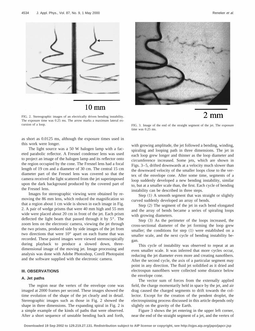
The region near the vertex of the envelope cone wimaged at 2000 frames per second. These images showetime evolution of the shape of the jet clearly and in detaStereographic images such as those in Fig. 2 showedshape in three dimensions. The expanding spiral in Fig.a simple example of the kinds of paths that were observAfter a short sequence of unstable bending back and fo
FIG. 2. Stereographic images of an electrically driven bending instabiThe exposure time was 0.25 ms. The arrow marks a maximum lateracursion of a loop.
Downloaded 19 Sep 2002 to 129.219.27.131. Redistribution subject to A
in
-edtoal
heedof
-o.
eh
mslly-dnt
sthe.heisd.h,
with growing amplitude, the jet followed a bending, windinspiraling and looping path in three dimensions. The jeteach loop grew longer and thinner as the loop diametercircumference increased. Some jets, which are shownFigs. 3–5, drifted downwards at a velocity much slower ththe downward velocity of the smaller loops close to the vtex of the envelope cone. After some time, segments oloop suddenly developed a new bending instability, simito, but at a smaller scale than, the first. Each cycle of bendinstability can be described in three steps.
Step~1! A smooth segment that was straight or slighcurved suddenly developed an array of bends.
Step~2! The segment of the jet in each bend elongaand the array of bends became a series of spiraling lowith growing diameters.
Step ~3! As the perimeter of the loops increased, tcross-sectional diameter of the jet forming the loop grsmaller; the conditions for step~1! were established on asmaller scale, and the next cycle of bending instability bgan.
This cycle of instability was observed to repeat ateven smaller scale. It was inferred that more cycles ocreducing the jet diameter even more and creating nanofibAfter the second cycle, the axis of a particular segment mpoint in any direction. The fluid jet solidified as it dried anelectrospun nanofibers were collected some distance bethe envelope cone.
The vector sum of forces from the externally applifield, the charge momentarily held in space by the jet, anddrag caused the charged segments to drift towards thelector. Except for the creation of the pendent droplet,electrospinning process discussed in this article dependsslightly on the gravity of the Earth.
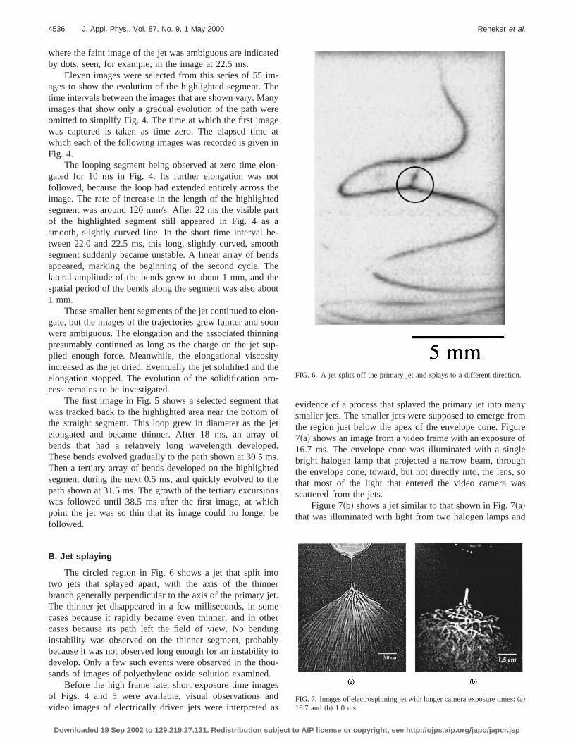
Figure 3 shows the jet entering in the upper left cornnear the end of the straight segment of a jet, and the verte
.x-
FIG. 3. Image of the end of the straight segment of the jet. The expotime was 0.25 ms.
IP license or copyright, see http://ojps.aip.org/japo/japcr.jsp

ewengTyesthe
erapgegid
lsgo
h
ofcn
bil-ets.
m-pek tothe
gehee,
im-en-
rm
ghthe
edt oft ofdms
izedces
er The
4535J. Appl. Phys., Vol. 87, No. 9, 1 May 2000 Reneker et al.
the envelope cone, where the first bending instability grSeveral segments of the jet are shown, including segmfrom slowly moving loops that formed earlier. All these sements are connected by segments that are not shown.smooth segments cross each other in this image, as thenearly horizontally across the bottom of the image. Thtwo segments are noticeably thinner than the jet enteringimage because the jet elongated as time evolved. Thslowly moving segments were part of large loops and waffected both by air drag and by the disturbance of theplied electrical field caused by the presence of both charsegments of the jet and charged nanofibers below the rebeing observed. Such slowly moving segments remaineview for many frames.
Two thinner segments that formed even earlier are aincluded in Fig. 3. One runs across the top half of the imaand the other runs across the bottom half. In the lowerthese segments the successive bends~step 1 of the secondcycle! were apparent. In the upper segment, the bendsalready developed into spiraling loops~step 2 of the secondcycle!. The pattern of dots visible in the lower left cornersFigs. 3–5 was caused by the pattern of facets on the refleof the halogen lamp used to illuminate this experime
FIG. 4. Evolution of electrical bending instability. The exposure times w0.25 ms. The width of each image was 5 mm.
Downloaded 19 Sep 2002 to 129.219.27.131. Redistribution subject to A
.ts
-woruneesee-d
onin
oe,f
ad
tort.
These dots are not evidence of the familiar varicose instaity that may cause a liquid jet to become a series of droplNo varicose instability was observed in this experiment.
Using a set of image files created by the electronic caera, it was often possible to follow the evolution of the shaof spiraling segments, such as those shown in Fig. 3, bacthe straight segment that entered the upper left corner ofimage. In Figs. 4 and 5, the light ellipse in the first imamarks a segment that evolved in an interesting way. Tselected segment of the jet was followed forward in timfrom the moment it entered the region contained in theages until it elongated, looped, became unstable, bent,tered the next cycle, and ultimately became too thin to foan image.
Figure 4 starts with a bend near the end of the straisegment of a jet entering the image at the upper left. Tonset of the electrically driven bending instability occurrjust before the jet entered the image. The straight segmenthe jet extended upward, and is not shown. The segmenthe jet that is highlighted by the white ellipse was followefor 27.5 ms in a series of images that were recorded at 0.5intervals. The thinner segments of the jet were emphasby using the Photopaint 6 software to reproduce them. Pla
eFIG. 5. Images of secondary and tertiary cycles of bending instabilities.exposure time was 0.25 ms. The width of each image is 5 mm.
IP license or copyright, see http://ojps.aip.org/japo/japcr.jsp
te
imh
anere
ei
lonot
tea
e-otn
Ththbo
loonisuitth
ro
th
j
emtethonchb
toejemthinbyo
d.gena
anyromureof
gleghsoas
d
.
:
4536 J. Appl. Phys., Vol. 87, No. 9, 1 May 2000 Reneker et al.
where the faint image of the jet was ambiguous are indicaby dots, seen, for example, in the image at 22.5 ms.
Eleven images were selected from this series of 55ages to show the evolution of the highlighted segment. Ttime intervals between the images that are shown vary. Mimages that show only a gradual evolution of the path womitted to simplify Fig. 4. The time at which the first imagwas captured is taken as time zero. The elapsed timwhich each of the following images was recorded is givenFig. 4.
The looping segment being observed at zero time egated for 10 ms in Fig. 4. Its further elongation was nfollowed, because the loop had extended entirely acrossimage. The rate of increase in the length of the highlighsegment was around 120 mm/s. After 22 ms the visible pof the highlighted segment still appeared in Fig. 4 assmooth, slightly curved line. In the short time interval btween 22.0 and 22.5 ms, this long, slightly curved, smosegment suddenly became unstable. A linear array of beappeared, marking the beginning of the second cycle.lateral amplitude of the bends grew to about 1 mm, andspatial period of the bends along the segment was also a1 mm.
These smaller bent segments of the jet continued to egate, but the images of the trajectories grew fainter and swere ambiguous. The elongation and the associated thinpresumably continued as long as the charge on the jetplied enough force. Meanwhile, the elongational viscosincreased as the jet dried. Eventually the jet solidified andelongation stopped. The evolution of the solidification pcess remains to be investigated.
The first image in Fig. 5 shows a selected segmentwas tracked back to the highlighted area near the bottomthe straight segment. This loop grew in diameter as theelongated and became thinner. After 18 ms, an arraybends that had a relatively long wavelength developThese bends evolved gradually to the path shown at 30.5Then a tertiary array of bends developed on the highlighsegment during the next 0.5 ms, and quickly evolved topath shown at 31.5 ms. The growth of the tertiary excursiwas followed until 38.5 ms after the first image, at whipoint the jet was so thin that its image could no longerfollowed.
B. Jet splaying
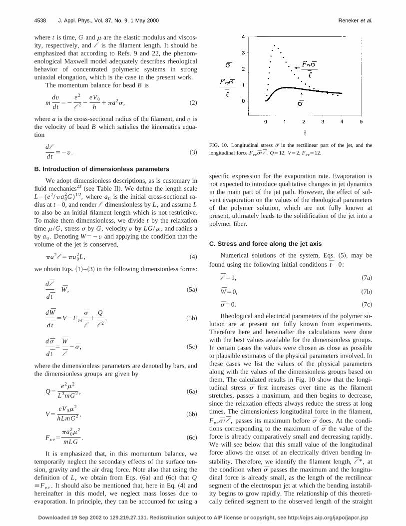
The circled region in Fig. 6 shows a jet that split intwo jets that splayed apart, with the axis of the thinnbranch generally perpendicular to the axis of the primaryThe thinner jet disappeared in a few milliseconds, in socases because it rapidly became even thinner, and in ocases because its path left the field of view. No bendinstability was observed on the thinner segment, probabecause it was not observed long enough for an instabilitdevelop. Only a few such events were observed in the thsands of images of polyethylene oxide solution examine
Before the high frame rate, short exposure time imaof Figs. 4 and 5 were available, visual observations avideo images of electrically driven jets were interpreted
Downloaded 19 Sep 2002 to 129.219.27.131. Redistribution subject to A
d
-eye
atn
-thedrta
hdseeut
n-onngp-
ye
-
atofetofd.s.des
e
rt.eerglytou-
sds
evidence of a process that splayed the primary jet into msmaller jets. The smaller jets were supposed to emerge fthe region just below the apex of the envelope cone. Fig7~a! shows an image from a video frame with an exposure16.7 ms. The envelope cone was illuminated with a sinbright halogen lamp that projected a narrow beam, throuthe envelope cone, toward, but not directly into, the lens,that most of the light that entered the video camera wscattered from the jets.
Figure 7~b! shows a jet similar to that shown in Fig. 7~a!that was illuminated with light from two halogen lamps an
FIG. 6. A jet splits off the primary jet and splays to a different direction
FIG. 7. Images of electrospinning jet with longer camera exposure times~a!16.7 and~b! 1.0 ms.
IP license or copyright, see http://ojps.aip.org/japo/japcr.jsp

err
anns
aliicigthy
eningim
poin
njeedi
nao
vealice
.
ascanp
ee
opshey
a-thevedce.is
s ofun-in
col-a-.
nhehetaticpa-heir
-
s o part
4537J. Appl. Phys., Vol. 87, No. 9, 1 May 2000 Reneker et al.
photographed with a video camera. The two lamps wabove and behind the jet. One was to the left and the otheright. This provided a broader source of illumination ththat used for Fig. 7~a!, but not as uniform as the Fresnel learrangement shown in Fig. 1. An exposure time of 1 ms wused. The part of the straight jet with small bending amptude is visible as are the loops containing segments, whhad turned so that the axis of the segment formed a hangle with the axis of the straight segment. The parts ofjet nearer the vertex of the envelope cone appeared onlshort, unconnected lines. Specular reflections of the beamlight, called glints, from one or the other of the two haloglamps off nearly horizontal segments of downward movloops were shown to be the cause of these bright spots. Slar bright spots moved downwards during the longer exsure of Fig. 7~a!, and created the lines that are prominentFig. 7~a!.
The video frame rate of 30 frames per second wasfast enough to follow the smooth development of thepath. At this frame rate, for any particular frame, the precing and the following frames showed loops and spiralscompletely different positions. Only after the illuminatiowas improved, described in Sec. II, and the high frame relectronic camera used was it obvious that the envelope cwas occupied by one long, flowing, continuous, and ethinner jet. The repeated cycles of ever smaller electricdriven bending instabilities created a complex path in whthe directions of the axes of the connected segments woften different and changing, sometimes by large angles
C. Coiled and looped jets captured on a hard surface
Nanofibers were sometimes collected by moving a glmicroscope slide, a metal screen, or other solid surfathrough the conical envelope. Figure 8 shows that coiledlooped nanofibers collected in this way were similar in shato the bending instabilities photographed with the high sp
FIG. 8. Scanning electron micrograph of coiled and looped nanofiberthe surface of an aluminum collector.
Downloaded 19 Sep 2002 to 129.219.27.131. Redistribution subject to A
eto
s-hheasof
i--
ott-
n
tener
lyhre
sesded
camera. The abundance and single coil of the coiled lodepended on the distance below the vertex at which twere collected.
The well-known tendency9 of a straight liquid jet mov-ing in its axial direction to coil when it impacts a hard, sttionary surface and buckles could account for some ofobserved coils. This mechanical effect is easily obserwhen a gravity driven jet of honey falls onto a hard surfaThe occurrence of mechanical buckling during impactlikely to be infrequent because most of the long segmentthe jet were moving in a sidewise direction as they encotered the collector. It is interesting to hypothesize thatthese experiments the coils and loops solidified beforelection. Then, the collected coils and loops provide informtion about the smallest bending instabilities that occurred
IV. MATHEMATICAL DESCRIPTION OF A JET
A. Viscoelastic model of a rectilinear electrified liquidjet
Consider first a rectilinear electrified liquid jet in aelectric field parallel to its axis. We model a segment of tjet by a viscoelastic dumbbell as shown in Fig. 9. In tmathematical description, we use the Gaussian electrossystem of units. Corresponding SI units are given whenrameters are evaluated. Table I lists the symbols and tunits.
Each of the beads,A and B, possesses a chargee andmassm. Let the position of beadA be fixed by non-Coulombforces. The Coulomb repulsive force acting on beadB is2e2/l 2. The force applied toB due to the external field is2eV0 /h. The dumbbell,AB, models a viscoelastic Maxwellian liquid jet. Therefore the stress,s, pulling B back toA is given by21
ds
dt5G
dl
l dt2
G
ms, ~1!
nFIG. 9. Viscoelastic dumbbell representing a segment of the rectilinearof the jet.
IP license or copyright, see http://ojps.aip.org/japo/japcr.jsp
s-eoican
k.
a-
ye-
e
e
:
,
wteth
g
n isics
ol-tersta
so-ts.oneps.sible. Interson
gi-ntease,longnt,
dly.alin-
u-arbil-ti-ight
e
4538 J. Appl. Phys., Vol. 87, No. 9, 1 May 2000 Reneker et al.
wheret is time,G andm are the elastic modulus and viscoity, respectively, andl is the filament length. It should bemphasized that according to Refs. 9 and 22, the phenenological Maxwell model adequately describes rheologbehavior of concentrated polymeric systems in strouniaxial elongation, which is the case in the present wor
The momentum balance for beadB is
mdvdt
52e2
l 2 2eV0
h1pa2s, ~2!
wherea is the cross-sectional radius of the filament, andv isthe velocity of beadB which satisfies the kinematics eqution
dl
dt52v. ~3!
B. Introduction of dimensionless parameters
We adopt dimensionless descriptions, as is customarfluid mechanics23 ~see Table II!. We define the length scalL5(e2/pa0
2G)1/2, wherea0 is the initial cross-sectional radius att50, and renderl dimensionless byL, and assumeLto also be an initial filament length which is not restrictivTo make them dimensionless, we dividet by the relaxationtime m/G, stresss by G, velocity v by LG/m, and radius aby a0 . DenotingW52v and applying the condition that thvolume of the jet is conserved,
pa2l 5pa02L, ~4!
we obtain Eqs.~1!–~3! in the following dimensionless forms
dl
d t5W, ~5a!
dW
d t5V2Fve
s
l1
Q
l 2, ~5b!
ds
d t5
W
l2s, ~5c!
where the dimensionless parameters are denoted by barsthe dimensionless groups are given by
Q5e2m2
L3mG2 , ~6a!
V5eV0m2
hLmG2 , ~6b!
Fve5pa0
2m2
mLG. ~6c!
It is emphasized that, in this momentum balance,temporarily neglect the secondary effects of the surfacesion, gravity and the air drag force. Note also that usingdefinition of L, we obtain from Eqs.~6a! and ~6c! that Q[Fve . It should also be mentioned that, here in Eq.~4! andhereinafter in this model, we neglect mass losses dueevaporation. In principle, they can be accounted for usin
Downloaded 19 Sep 2002 to 129.219.27.131. Redistribution subject to A
m-l
g
in
.
and
en-e
toa
specific expression for the evaporation rate. Evaporationot expected to introduce qualitative changes in jet dynamin the main part of the jet path. However, the effect of svent evaporation on the values of the rheological parameof the polymer solution, which are not fully known apresent, ultimately leads to the solidification of the jet intopolymer fiber.
C. Stress and force along the jet axis
Numerical solutions of the system, Eqs.~5!, may befound using the following initial conditionst 50:
l 51, ~7a!
W50, ~7b!
s50. ~7c!
Rheological and electrical parameters of the polymerlution are at present not fully known from experimenTherefore here and hereinafter the calculations were dwith the best values available for the dimensionless grouIn certain cases the values were chosen as close as posto plausible estimates of the physical parameters involvedthese cases we list the values of the physical paramealong with the values of the dimensionless groups basedthem. The calculated results in Fig. 10 show that the lontudinal stresss first increases over time as the filamestretches, passes a maximum, and then begins to decrsince the relaxation effects always reduce the stress attimes. The dimensionless longitudinal force in the filameFves/ l , passes its maximum befores does. At the condi-tions corresponding to the maximum ofs the value of theforce is already comparatively small and decreasing rapiWe will see below that this small value of the longitudinforce allows the onset of an electrically driven bendingstability. Therefore, we identify the filament length,l * , atthe condition whens passes the maximum and the longitdinal force is already small, as the length of the rectilinesegment of the electrospun jet at which the bending instaity begins to grow rapidly. The relationship of this theorecally defined segment to the observed length of the stra
FIG. 10. Longitudinal stresss in the rectilinear part of the jet, and th
longitudinal forceFves/ l . Q512, V52, Fve512.
IP license or copyright, see http://ojps.aip.org/japo/japcr.jsp

ejer
aesngtece
e
aif
eral
to
y,jeis
o
ofe
thec-
oesthe
ead
beates
cting
arn-
der
es
e--
-elec-12
an
4539J. Appl. Phys., Vol. 87, No. 9, 1 May 2000 Reneker et al.
segment is not yet determined. The length,l * , increaseswith the applied voltage as is seen in Fig. 11. Near the pdent drop, the longitudinal force is also small, but thedoes not bend, since its radius there is large, and the cosponding bending stiffness is large.
Thin rectilinear liquid jets are unstable to capillary~vari-cose! perturbations driven by surface tension. Longitudinstretching can stabilize the jet in the presence of thperturbations.24 In electrospinning, jets are stretched alotheir axis by the external electric field and are elongafurther by the repulsive force between charges on adjasegments. The resulting tensile forces prevent developmof capillary instability in the experiments reported here.
D. Effects from aerodynamics and gravity are small
For an uncharged jet moving in air at high speed,aerodynamically driven bending instability may set inrav2.a/a, wherera is the air density,v the jet velocity,anda the surface tension coefficient.7–9 Taking, for example,ra51.21 kg/m3, v;0.5 m/s, a;0.1 kg/s2, and a;1024 m,we estimaterav2;0.3 kg/m s2, which is much smaller thana/a;103 kg/m s2. Therefore, under the conditions charactistic of experiments on electrospinning, the aerodynamicdriven bending instability does not occur.
The air drag force per unit jet length, which tendscompress the jet along its axis, is given by25
f a5parav20.65S 2va
naD 20.81
, ~8!
wherera andna are the air density and kinematic viscositrespectively. The gravity force per unit length pulling thedownward in the experimental geometry shown in Fig. 1
f g5rgpa2, ~9!
wherer is the liquid density andg is the acceleration due tgravity.
In the momentum balance, Eq.~2! or ~5b!, we neglectedf g as a secondary effect. The air drag forcef a is even smallerthan f g . Taking ra51.21 kg/m3, na50.1531024 m2/s, r51000 kg/m3, v50.5 m/s, anda5150mm we obtain fromEqs. ~8! and ~9! f a51.431025 kg/s2 and f g56.9
FIG. 11. Length of the rectilinear part of the jetl * as a function of thedimensionless voltageV. Q512 andFve512.
Downloaded 19 Sep 2002 to 129.219.27.131. Redistribution subject to A
n-tre-
le
dntnt
n
-ly
t
31024 kg/s2. The compressive stress along the jet axisthe air drag is negligibly small in comparison with thstretching due to gravity, and is much smaller thanstretching due to the electrical forces. Buckling of the eletrospun jet due to the compressive force from air drag dnot occur, since the electrical forces that tend to elongatejet are larger and dominate any perturbation that might lto buckling.
E. Bending instability of electrified jets
The reason for the observed bending instability mayunderstood in the following way. In the coordinates thmove with a rectilinear electrified jet, the electrical chargcan be regarded as a static system of charges interamainly by Coulomb’s law~without the external field!. Suchsystems are known to be unstable according to the Eshaw’s theorem.26 To illustrate the instability mechanismthat is relevant in the electrospinning context, we consithree point-like charges, each with a valuee, and originallyin a straight line atA, B, andC as shown in Fig. 12. TwoCoulomb forces having magnitudesF5e2/r 2 push againstchargeB from opposite directions. If a perturbation causpoint B to move off the line by a distanced to B8, a net forceF152F cosu5(2e2/r3)•d acts on chargeB in a direction per-pendicular to the line, and tends to causeB to move furtherin the direction of the perturbation away from the line btween fixed charges,A andC. The growth of the small bending perturbation that is characterized byd is governed in thelinear approximation by the equation
md2d
dt25
2e2
l 13 d, ~10!
wherem is the mass.The growing solution of this equation, d
5d0 exp@(2e2/ml 13)1/2t#, shows that small perturbations in
crease exponentially. The increase is sustained becausetrostatic potential energy of the system depicted in Fig.decreases ase2/r when the perturbations, characterized byd
FIG. 12. Illustration of the Earnshaw instability, leading to bending ofelectrified jet.
IP license or copyright, see http://ojps.aip.org/japo/japcr.jsp

blin
slitthtife
e-
eea
by
ryang
n
cerv
faeeec
ted
rre
t
b
sFig.et
ent
to
cted
4540 J. Appl. Phys., Vol. 87, No. 9, 1 May 2000 Reneker et al.
and r , grow. We believe that this mechanism is responsifor the observed bending instability of jets in electrospning.
If chargesA, B, andC are attached to a liquid jet, forceassociated with the liquid tend to counteract the instabicaused by the Coulomb forces. For very thin liquid jets,influence of the shearing force related to the bending sness can be neglected in comparison with the stabilizingfect of the longitudinal forces since the shearing forces arthe order ofO(a4), which is much smaller than the longitudinal forces,9 which are of the order ofO(a2). The longitu-dinal force, at the moment when the bending instability sin, was calculated above for the stretching of a rectilinfilament. Its value is given byf l 5pa2s* ~or in dimension-less form byFves* / l * !. The values ofs and l at the mo-ment whens ~or s! passes its maximum are denotedasterisks. The forcesf l are directed alongBC or BA in Fig.12, and are opposite to the local Coulomb forceF. If F islarger than the viscoelastic resistancef l , the bending per-turbation continues to grow, but at a rate decelerated byf l .
It might be thought that bending perturbations of veshort lengths can always overcome the viscoelastic resistf l , since the Coulomb force increases when the wavelenof the perturbation decreases. In fact, the surface tensioways counteracts the bending instability because bendingways leads to an increase of the area of the jet surfa9
Surface tension resists the development of too large a cuture by the perturbationABC in Fig. 12, and therefore limitsthe smallest possible perturbation wavelengths. All thesetors are accounted for in the description of the thrdimensional bending instability of electrospun jets in SIV F.
F. Three-dimensional equations of the dynamics ofthe electrospun jets
We represent the electrospun jets by a model systembeads possessing chargee and massm connected by vis-coelastic elements as shown in Fig. 13, which generalizesmodels of Figs. 9 and 12. It needs to be mentioned that thimaginary beads are not the same as the physical bea20
resulting from the varicose instability. The parameters cosponding to the element connecting beadi with bead (i11) are denoted by subscriptu ~up!, those for the elemenconnecting beadi with ( i 21) by subscriptd ~down!. Thelengthsl ui and l di of these elements are given by
l ui5@~xi 112xi !21~yi 112yi !
21~zi 112zi !2#1/2,
~11a!
l di5@~xi2xi 21!21~yi2yi 21!21~zi2zi 21!2#1/2,~11b!
respectively, wherexi ,yi ,zi ,..., are theCartesian coordi-nates of the beads.
The rates of strain of the elements are given(dl ui /dt)/l ui and (dl di /dt)/l di . The viscoelastic forcesacting along the elements are similar to Eq.~1!,
dsui
dt5G
1
l ui
dl ui
dt2
G
msui , ~12a!
Downloaded 19 Sep 2002 to 129.219.27.131. Redistribution subject to A
e-
yef-f-of
tsr
cethal-al-.a-
c--.
of
heses-
y
dsdi
dt5G
1
l di
dl di
dt2
G
msdi . ~12b!
The total number of beads,N, increases over time anew electrically charged beads are inserted at the top of13 to represent the flow of solution into the jet. The nCoulomb force acting on thei th bead from all the otherbeads is given by
fC5 (j 51,N
j Þ i
e2
Ri j2 F i
xi2xj
Ri j1 j
yi2yj
Ri j1k
zi2zj
Ri jG , ~13!
where i, j , andk are the unit vectors along thex, y, andzaxes, respectively, and
Ri j 5@~xi2xj !21~yi2yj !
21~zi2zj !2#1/2. ~14!
The electric force imposed on thei th bead by the electricfield created by the potential difference between the penddrop and the collector is
f052eV0
hk. ~15!
It is clear that the gravitational force, already shownbe small, may be included inf0 , as is done later in thisarticle to create a hypothetical uncharged jet.
The net viscoelastic force acting on thei th bead of thejet is
fve5paui2 suiF i
xi 112xi
l ui1 j
yi 112yi
l ui1k
zi 112zi
l uiG
2padi2 sdiF i
xi2xi 21
l di1 j
yi2yi 21
l di1k
zi2zi 21
l diG ,~16!
FIG. 13. Bending electrospun jet modeled by a system of beads conneby viscoelastic elements.
IP license or copyright, see http://ojps.aip.org/japo/japcr.jsp

ct
rt
ne
eripel
tott
ule
ay,
s itel-l-
ofm arlly,
m-
e inur-
new
ingy
he14
offith
nceeadshemess is
4541J. Appl. Phys., Vol. 87, No. 9, 1 May 2000 Reneker et al.
where, when mass is conserved and evaporation neglethe filament radiiaui andadi are given by
paui2 l ui5pa0
2L, ~17a!
padi2 l di5pa0
2L, ~17b!
which is similar to Eq.~4!.The surface tension force acting on thei th bead, and
tending to restore the rectilinear shape of the bending pathe jet, is given by
fcap52ap~a2!avki
~xi21yi
2!1/2 @ iuxi usign~xi !1 j uyi usign~yi !#, ~18!
wherea is the surface tension coefficient,ki is the jet curva-ture calculated using the coordinates of beads (i 21), i and( i 11), and (a2)av5(aui1adi)
2/4. The meaning of ‘‘sign’’is as follows:
sign~x!51, if x.0,
sign~x!521, if x,0, ~19!
sign~x!50, if x50.
Setting the forces described in Eqs.~13!, ~15!, ~16!, and~18! equal to mass times acceleration, according to Newtosecond law, we obtain the equation governing the radius vtor of the position of thei th beadr i5 ixi1 jyi1kzi in thefollowing form:
md2r i
dt25 (
j 51,Nj Þ i
e2
Ri j3 ~r i2r j !2e
V0
hk1
paui2 sui
l ui~r i 112r i !
2padi
2 sdi
l di~r i2r i 21!2
ap~a2!avki
~xi21yi
2!1/2
3@ iuxi usign~xi !1 j uyi usign~yi !#. ~20!
For the first bead,i 51, and N, the total number ofbeads, is also 1. As more beads are added,N becomes largerand the first beadi 51 remains at the bottom end of thgrowing jet. For this bead, all the parameters with subscd should be set equal to zero since there are no beads bi 51.
G. Spatial and temporal perturbation of the rectilinearsegment
Both space and time dependent perturbations lead todevelopment of the electrically driven bending instability. Tmodel the way a spatial perturbation develops, we denotelast bead pulled out of the pendent drop and added atupper end of the jet byi 5N. When the distancel d,N be-tween this bead and the pendent drop becomes long enosay, h/25 000, a new beadi 5N11 is inserted at a smaldistance, say,h/50 000, from the previous one. At the samtime a small perturbation is added to itsx andy coordinates,
xi51023L sin~vt !, ~21a!
yi51023L cos~vt !. ~21b!
Herev is the perturbation frequency. The condition ththe collector atz50 is impenetrable is enforced numericall
Downloaded 19 Sep 2002 to 129.219.27.131. Redistribution subject to A
ed,
of
’sc-
tow
he
hehe
gh,
t
and the charge on each element of the jet is removed aarrives at the collector. Such a calculation mimics the devopment of the electrically driven bending instability. The caculation begins with only two beads,N52. As the jet flows,the number of beads in the jet,N, increases.
It is also possible to consider the temporal instabilityan established jet. In this case the calculation began frolong rectilinear filament 0<z<h containing a fixed numbeof beads. The filament was perturbed by moving it lateraat t50, everywhere along its axis by the function
x51023L cosS 2p
lzD h2z
h, ~22a!
y51023L sinS 2p
lzD h2z
h, ~22b!
wherel is the wavelength of the perturbation. Then the teporal evolution of the path was calculated.
In all cases, the system of Eqs.~12! and~20! was solvednumerically, assuming that the stressessui andsdi and theradial velocitydr i /dt were zero att50. The equations weremade dimensionless by the same scale factors as thosSec. IV B. Since here it is necessary to account for the sface tension and for the perturbing displacements, threedimensionless groups emerge in addition to those of Eqs.~6!,
A5apa0
2m2
mL2G2 , ~23a!
Ks5vm/G, ~23b!
Kt52pL
l. ~23c!
The last dimensionless group needed is formed by dividthe distanceh, from the collector to the pendent droplet, bL,
H5h
L. ~24!
V. RESULTS AND DISCUSSION
A. Jet path calculated from the electrically drivenbending instability
We begin with the calculation of the development of ttemporal perturbation into the bending instability. Figureshows that the small perturbation, Eqs.~22!, increased dra-matically as the Earnshaw-like instability grew. The paththe electrified jet att 50.89 is represented by a helix oincreasing radial dimension and a pitch commensurate wthe radial dimension. It is emphasized that the jet att 50would appear on the scale of Fig. 14 as a straight line, sithe initial helix radius is very small in comparison to thother dimensions. As the calculation progresses, the bemove further and further apart. Since, in this model, tbeads are connected by straight lines, the graph becoquite irregular when the separation between the beadlarger than the radius of the spiral path.
IP license or copyright, see http://ojps.aip.org/japo/japcr.jsp

o
n
adlo-
i-
14nspotridegIt
ve
tit
acht ofhe
tal-d-d-henandat
aceheandce
easersttheentde-
tedterslaysin
eo
arelled
-y ashebeto
ings as
bi-ethe
Thecepath
in
ncethetionusedpo-
egdia
am
4542 J. Appl. Phys., Vol. 87, No. 9, 1 May 2000 Reneker et al.
Consider now the development of perturbations intobending instability in a realistic jet~spatial instability!. Weestimate the charge carried by the jet to be 1 C/l, which isthe same order as the values measured.20 We also estimatethat the relaxation timeu is 10 ms,a0 is 150 mm, r is103 kg/m3, h is 2 m, V0 is 10 kV, a is 0.7 kg/s2, andm is103 kg/~m s!. The value ofm is taken to be much larger thathe zero-shear viscositym0 reported,20 since the strong lon-gitudinal flows we are dealing with in the present work leto an increase, by several orders of magnitude, of the egational viscosity fromm0 .9,22,27,28 The dimensionless parameters are as follows:Q5Fve578359.6, V5156.7, A517.19, andH5626.9. The length scale isL53.19 mm.The charge on the bead e58.48~g1/2cm3/2!/s52.8331029 C. The mass of each bead ism50.28331028 kg. The value ofKs is taken as 100. Sinceu5m/G510 ms, this value corresponds tov5104 s21, which is inthe frequency range of typical noise in the laboratory.
Figures 15~a!–15~e! illustrate the development of a typcal jet path. The time periodic perturbation, Eqs.~21!, thatgrows along the jet is similar to the case shown in Fig.The jet flows continuously from the pendent drop in respoto the electric field established by the externally appliedtential between the droplet and the collector. This elecfield also causes the jet to be charged as it leaves the pendrop. At t 50.99 in Fig. 15~e! the instantaneous path of thjet is similar to the patterns recorded in experiments usinhigh speed video camera such as those shown in Fig. 2.emphasized that the stressessui and sdi are positive alongthe entire jet in Figs. 15~a!–15~e!, which means that thewhole jet is stretched continuously.
In Fig. 15, a long segment near the vertex of the enlope cone is plotted in thex, y, andz coordinates at varioustimes and scales to show details of the jet path. The enlength of both the straight segment and the spiral par
FIG. 14. Temporal growth of the bending instability along the straight sment of a charged jet subject to a small perturbation that is initially perioin space. The growth of the lateral excursions is larger than that usuobserved to show details of the model. The following values of the par
eters were used:Q550, V540, Fve550, A50, Kt51, and H5100; t50.89. The number of beadsN5100.
Downloaded 19 Sep 2002 to 129.219.27.131. Redistribution subject to A
a
f
n-
.e-cent
ais
-
reis
shown at the same scale in the inset at the upper right of epart of Fig. 15. An ellipse in each inset encloses the parthe jet path shown in the corresponding coordinate box. Tpendent drop was always atx50, y50, andz5h.
The experimental evidence shows a self-similar, fraclike process of development of the electrically driven bening instabilities. The diameter of the first generation of bening loops becomes larger and the jet becomes thinner. Tmuch smaller bending perturbations set in on these loopsbegin to grow also. This self-similar process continuessmaller and smaller scales until viscoelastic force, surftension or solidification of the jet arrest further bending. Tnumerical results in Fig. 15 describe only the emergencegrowth of the first cycle of the loops. This is a consequenof the fact that the distances between the beads increnormously in the simulation of the development of the ficycle. No new beads were added except at the top ofrectilinear segment. Therefore the capability of the prescomputer code to elucidate smaller details of the pathcreases as the jet elongates enormously.
Figure 16 shows the path of a charged jet calculafrom a realistic but different set of dimensionless parameand perturbations than was used in Fig. 15. The path dispa bending instability generally similar to that shownFig. 15.
To show that the bending instability is driven by thCoulomb interaction, the charge,e, on the beads is taken tbe zero so thatQ50. The electrical driving force for thebending instability is then zero, but the other parametersexactly the same as those in Fig. 16. If a jet were then pudownward by gravity, which can supply a downward component of force that acts on the segment in the same wathe downward component of the electrical force from telectrical field, one would expect the uncharged jet toalmost straight in spite of the small perturbations appliedit, since the perturbations would not develop into a bendinstability. The calculated result with the same parameterthose in Fig. 16, butQ50, is in fact a straight jet growing
downward, even at a later time (t 58.99). Increasing theratio of the surface tension to the Coulomb force also stalizes a charged jet. IfA is increased to 9, by increasing thsurface tension while all the other parameters are keptsame as those in Fig. 16 practically no bending occurs.results for the gravity driven jet and for the high surfatension jet are not shown because the calculated jetcannot be distinguished from a straight line at the scaleFig. 16.
B. Measurements of the trajectory and velocity of aparticular segment of a jet
Figure 17 is derived from measurements of a sequeof stereographic images of the part of a jet just belowapex of the envelope cone. The polyethylene oxide soluin water and ethanol that was used is the same as thatfor Figs. 4 and 5. The exposure time was 0.25 ms. The
-clly-
IP license or copyright, see http://ojps.aip.org/japo/japcr.jsp

4543J. Appl. Phys., Vol. 87, No. 9, 1 May 2000 Reneker et al.
FIG. 15. Perturbations develop into a bending instability. The dimensionless groups have the following values:Q5Fve578359.6,V5156.7,A517.19,
Ks5100,H5626.9.~a! t 50.19, ~b! 0.39, ~c! 0.59, ~d! 0.79, and~e! 0.99.
umee
theether of
sition projected into the plane of the image of the maximlateral excursion of a loop, an example of which is markwith an arrow in Fig. 2, was followed as a function of timfor 8 ms.
Downloaded 19 Sep 2002 to 129.219.27.131. Redistribution subject to A
dFigure 17 shows the downward displacement of
maximum lateral excursion from its initial position. Thdownward motion of the jet predicted by the model andvalue measured from the experiment are of the same orde
IP license or copyright, see http://ojps.aip.org/japo/japcr.jsp

ice19alu
ons
rd
nt
sd
aleg
hexi-lar
notnt,
6,b-layn-
hat
iont toseg-insol-ratiotra-as
nd-
t a
ning
s on
4544 J. Appl. Phys., Vol. 87, No. 9, 1 May 2000 Reneker et al.
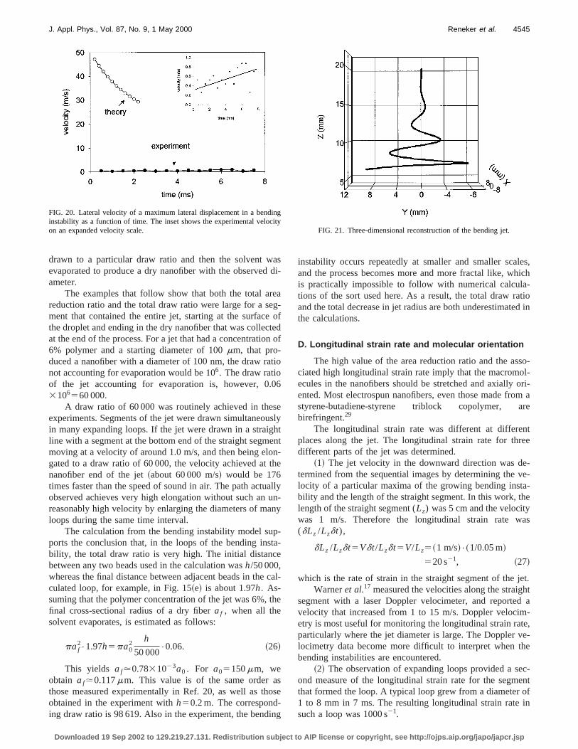
magnitude. Figure 18 shows the downward velocity, whdecreased from about 1.1 to about 0.8 m/s. The increasthe radial displacement of the maximum is shown in Fig.The measured radial velocity was nearly constant at a vof 0.5 m/s, as shown in Fig. 20.
The displacements of the maximum lateral excursigiven in Figs. 17 and 19, were fitted by the following expresion, wherez is measured from the pendent drop downwa
x50.0257t2 cost,
y50.0257t2 sint, ~25!
z520 exp~20.0595t !.
Figure 21 is a three-dimensional plot of this equatioThe position of ‘‘maximum lateral excursion of a loop’’ thawas used as a reference to determine the velocities doenecessarily move in the same way as a marker embeddethe jet and carried with the jet. If a path with an ellipticloop were to rotate about its vertical axis, a changing s
FIG. 16. Charged jet with values of the dimensionless parameters tharealistic but different from those used in Fig. 15.Q5Fve512, V52, A
50.9, Ks5100,H5100, t 54.99.
FIG. 17. Downward movement of a maximum lateral displacement ibending instability as a function of time.
Downloaded 19 Sep 2002 to 129.219.27.131. Redistribution subject to A
hin.e
,-:
.
notin
-
ment of the jet would be projected into the image plane. Tassumption that the velocity and displacement of the mamum lateral excursion represent the motion of a particusegment of the jet is essentially correct if the curve isrotating, but only elongating along the axis of the segmeand moving radially outwards and downwards.
The motion of a splay point such as that shown in Fig.which is attached to a particular point on the jet, was oserved in a series of stereo pictures. The motion of the sppoint was only downward and outward in a plane that cotained the y axis and a single radial direction, indicating trotation of the path was small.
C. Bending instability leads to large area reductionratios
The ‘‘area reduction ratio,’’ which is defined as the ratof the cross-sectional area of the upper end of a segmethe cross-sectional area at the lower end of the samement, is equal to the draw ratio if the volume of materialthe segment is conserved. Since in this experiment thevent evaporated during the process, the area reductionwas related to the draw ratio by the time varying concention of the solution. Here we assume that the fluid jet w
FIG. 18. Downward velocity of a maximum lateral displacement in a being instability as a function of time.
re
aFIG. 19. Lateral movement of a maximum lateral displacement in a bendinstability as a function of time. The inset shows the experimental resultan expanded distance scale.
IP license or copyright, see http://ojps.aip.org/japo/japcr.jsp
ad
reegeten
t
06
seushe
onth
aun
p-tae
c
th
so-in
les,hich-tiod in
so-ol-ori-m are
ntee
e-ve-a-he
as
jet.htd a
-te,e-
he
ec-entofin
incit
4545J. Appl. Phys., Vol. 87, No. 9, 1 May 2000 Reneker et al.
drawn to a particular draw ratio and then the solvent wevaporated to produce a dry nanofiber with the observedameter.
The examples that follow show that both the total areduction ratio and the total draw ratio were large for a sment that contained the entire jet, starting at the surfacthe droplet and ending in the dry nanofiber that was collecat the end of the process. For a jet that had a concentratio6% polymer and a starting diameter of 100mm, that pro-duced a nanofiber with a diameter of 100 nm, the draw ranot accounting for evaporation would be 106. The draw ratioof the jet accounting for evaporation is, however, 0.3106560 000.
A draw ratio of 60 000 was routinely achieved in theexperiments. Segments of the jet were drawn simultaneoin many expanding loops. If the jet were drawn in a straigline with a segment at the bottom end of the straight segmmoving at a velocity of around 1.0 m/s, and then being elgated to a draw ratio of 60 000, the velocity achieved atnanofiber end of the jet~about 60 000 m/s! would be 176times faster than the speed of sound in air. The path actuobserved achieves very high elongation without such anreasonably high velocity by enlarging the diameters of maloops during the same time interval.
The calculation from the bending instability model suports the conclusion that, in the loops of the bending insbility, the total draw ratio is very high. The initial distancbetween any two beads used in the calculation wash/50 000,whereas the final distance between adjacent beads in theculated loop, for example, in Fig. 15~e! is about 1.97h. As-suming that the polymer concentration of the jet was 6%,final cross-sectional radius of a dry fiberaf , when all thesolvent evaporates, is estimated as follows:
paf2•1.97h5pa0
2 h
50 000•0.06. ~26!
This yields af.0.7831023a0 . For a05150mm, weobtain af.0.117mm. This value is of the same order athose measured experimentally in Ref. 20, as well as thobtained in the experiment withh50.2 m. The corresponding draw ratio is 98 619. Also in the experiment, the bend
FIG. 20. Lateral velocity of a maximum lateral displacement in a bendinstability as a function of time. The inset shows the experimental veloon an expanded velocity scale.
Downloaded 19 Sep 2002 to 129.219.27.131. Redistribution subject to A
si-
a-
ofdof
io
lytnt-e
llyn-y
-
al-
e
se
g
instability occurs repeatedly at smaller and smaller scaand the process becomes more and more fractal like, wis practically impossible to follow with numerical calculations of the sort used here. As a result, the total draw raand the total decrease in jet radius are both underestimatethe calculations.
D. Longitudinal strain rate and molecular orientation
The high value of the area reduction ratio and the asciated high longitudinal strain rate imply that the macromecules in the nanofibers should be stretched and axiallyented. Most electrospun nanofibers, even those made frostyrene-butadiene-styrene triblock copolymer, abirefringent.29
The longitudinal strain rate was different at differeplaces along the jet. The longitudinal strain rate for thrdifferent parts of the jet was determined.
~1! The jet velocity in the downward direction was dtermined from the sequential images by determining thelocity of a particular maxima of the growing bending instbility and the length of the straight segment. In this work, tlength of the straight segment (Lz) was 5 cm and the velocitywas 1 m/s. Therefore the longitudinal strain rate w(dLz /Lzdt),
dLz /Lzdt5Vdt/Lzdt5V/Lz5~1 m/s!•~1/0.05 m!
520 s21, ~27!
which is the rate of strain in the straight segment of theWarneret al.17 measured the velocities along the straig
segment with a laser Doppler velocimeter, and reportevelocity that increased from 1 to 15 m/s. Doppler velocimetry is most useful for monitoring the longitudinal strain raparticularly where the jet diameter is large. The Doppler vlocimetry data become more difficult to interpret when tbending instabilities are encountered.
~2! The observation of expanding loops provided a sond measure of the longitudinal strain rate for the segmthat formed the loop. A typical loop grew from a diameter1 to 8 mm in 7 ms. The resulting longitudinal strain ratesuch a loop was 1000 s21.
gy
FIG. 21. Three-dimensional reconstruction of the bending jet.
IP license or copyright, see http://ojps.aip.org/japo/japcr.jsp

tete
is
as
hadia
nd
oral-
s
ecb
lycre
inonesseineaschsog
goowiethhep
ighteth
thjel
rre-ionhighthejet.
leds inepre-thert toen
ten-s inis-ereth’s
g
eshets
Thentaltersbet-rva-sticsta-
allychrn-the
e inu-id
eirapster-
i-S-
.S.the-hethegiftx.n-
atly
4546 J. Appl. Phys., Vol. 87, No. 9, 1 May 2000 Reneker et al.
~3! The overall longitudinal strain rate can be estimausing the data in Sec. V C. The time that a typical segmenthe electrospun jet is in flight (dt) can be estimated as thdistance between the pendent droplet and the collector~20cm! divided by the average downward velocity of the jet~1m/s!. The resultingdt is 0.2 s. The longitudinal strain ratedz/(dt•z), wherez is the initial segment length, anddz isthe growth in length. Sincedz is much greater thanz, dz isapproximately the final segment length. The ratiodz/z wasaround 105, and therefore the longitudinal strain rate waround 0.53106 s21. Using the estimate, Eq.~27!, we findthat in the straight segment the length of a liquid elementbeen approximately doubled, and the cross-sectional radecreased by a factor of 4. Then the longitudinal strain rin the loops becomes of the order of 105 s21. The actualvalue will be lower due to the effects of evaporation asolidification.
Theory suggests that the transformation from a randcoil to a stretched macromolecule occurs when the strainmultiplied by the conformational relaxation time of the moecule is greater than 0.5.27,28Since the relaxation time of thipolymer solution is about 0.01 s, thendz/(dt•z) multipliedby the relaxation time was equal to 10– 103, which is muchgreater than 0.5. Therefore the longitudinal flow in the eltrospun jet is strong, and the macromolecules are likely tostretched in the direction of the jet axis.
VI. SUMMARY AND CONCLUSIONS
The initial straight segment of a typical electricalcharged jet of polyethylene oxide aqueous solution wasated by an electrical potential applied between the penddrop and the collector. Then an electrically driven bendinstability, triggered by perturbations of the lateral positiand lateral velocity of the jet, grew. The repulsive forcbetween the charges carried with the jet caused everyment of the jet to lengthen continuously along a changpath until the jet solidified. The geometrically simple idthat the jet lengthened in a straight line along its axis leadan implausibly high velocity at the thin, leading end of sua straight jet. Instead, the jet bent and developed a serielateral excursions that grew into spiraling loops. Eachthese loops grew larger in diameter as the jet grew lonand became thinner.
About 20 ms after a loop had first formed, occurrinwithin a time interval of less than a millisecond, a new setelectrically driven bending instabilities appeared on the nthinner, smoothly curved loop. The new bending instabilitgrew when the jet in the loop was thin enough and whenviscoelastic stress along its axis had relaxed enough. Tnew bending instabilities developed into a smaller set of srals that looped around the path of the first loop.
The envelope cone observed at the end of the strasegment defined the region inside which this complex patthe jet developed. The cycles of bending instability repeain a self-similar manner until the solvent evaporated, andremaining polymer fiber resisted further elongation byCoulomb forces of the charge that was still present on theA very high reduction~as much as 105! in the cross-sectiona
Downloaded 19 Sep 2002 to 129.219.27.131. Redistribution subject to A
dof
suste
mte
-e
e-ntg
g-g
to
offer
f
sesei-
htofde
et.
area of the jet was achieved in this manner and the cosponding large increase in the jet length occurred in a regthat was only a few centimeters across. The associatedlongitudinal strain rate implies that, in the electrospun jet,macromolecular coils are stretched along the axis of the
Bending instabilities in electrospun jets were modeby a system of connected viscoelastic dumbbells. Beadthe dumbbells possess appropriate mass and charge to rsent the observed jets. The beads interacted with each oaccording to Coulomb’s law. The beads were also subjecthe electrical forces from the electrical field created betwethe pendent droplet and the collector by the imposed potial difference. Springs and dashpots, connecting the beadthe dumbbells, mimicked the Maxwellian viscoelastic restance to elongation of the jet. Surface tension effects walso included. Estimates showed that effects of the Eargravity, as well as aerodynamic forces~the drag and distrib-uted lift force!, were negligibly small in the electrospinninexperiments.
Equations of motion of the beads with all the forcacting in combination were used to follow, numerically, tevolution of the path of the electrically charged polymer jein the presence of spatial and temporal perturbations.results are in reasonable agreement with the experimeevidence. In spite of the fact that some material paramecan only be estimated at present, order of magnitude, orter, agreement between the theory and experimental obsetions was achieved. The theory showed that the viscoelaforce along the jet and the surface tension both tend tobilize the charged jet.
The entire electrospinning process and the electricdriven bending instabilities of an electrospun fluid can eabe viewed as particular examples of the very general Eashaw theorem in electrostatics. This theorem leads toconclusion that it is impossible to create a stable structurwhich the elements of the structure interact only by Colomb’s law. Charges on or embedded in a polymer flumove the fluid in quite complicated ways to reduce thCoulomb interaction energy. Electrospinning, and perhother useful processes, utilize this behavior to produce inesting and useful polymer objects.
For additional information on this topic, see Ref. 30.
ACKNOWLEDGMENTS
Support for this work was provided by the National Scence Foundation under Grant Nos. DMI-9813098 and CT9900949, by the U.S. Army Research Office, by the UArmy Soldier and Biological Systems Command, and byNonmetallic Materials Division of the U.S. Air Force Research Laboratory, Wright Patterson Air Force Base. Thigh-speed camera was acquired with support fromHayes Investment Fund of the Ohio Board of Regents. Afrom the DUPONT Company made it possible for Dr. AleYarin to make a productive visit to the University of AkronThe help of Dale Ertley and Dr. Dan Galehouse in the costruction of many specialized pieces of equipment is greappreciated.
IP license or copyright, see http://ojps.aip.org/japo/japcr.jsp

gy
in
inge
ore
4547J. Appl. Phys., Vol. 87, No. 9, 1 May 2000 Reneker et al.
1X. Lord Rayleigh, London, Edinburgh, Dublin Philos. Mag.44, 184~1882!.
2J. Zeleny, Phys. Rev.10, 1 ~1917!.3G. I. Taylor, Proc. R. Soc. London, Ser. A280, 383 ~1964!.4G. I. Taylor, J. Fluid Mech.22, 1 ~1965!.5G. I. Taylor, Proc. R. Soc. London, Ser. A291, 145 ~1966!.6G. I. Taylor, Proc. R. Soc. London, Ser. A313, 453 ~1969!.7A. L. Yarin, J. Appl. Mech. Tech. Phys.23, 39 ~1982!.8A. L. Yarin, J. Appl. Mech. Tech. Phys.27, 828 ~1986!.9A. L. Yarin, Free Liquid Jets and Films: Hydrodynamics and Rheolo~Longman, Harlow, and Wiley, New York, 1993!.
10V. M. Entov and A. L. Yarin, J. Fluid Mech.140, 91 ~1984!.11P. K. Baumgarten, J. Colloid Interface Sci.36, 71 ~1971!.12L. Larrondo, and R. St. J. Manley, J. Polym. Sci., Part B: Polym. Phys.19,
909 ~1981!.13L. Larrondo and R. St. J. Manley, J. Polym. Sci., Part B: Polym. Phys.19,
921 ~1981!.14L. Larrondo and R. St. J. Manley J. Polym. Sci., Part B: Polym. Phys.19,
933 ~1981!.15D. H. Reneker and I. Chun, Nanotechnology7, 216 ~1996!.16A. Formhals, U.S. Patent No. 1,975,504~filed 1934!.17S. B. Warner, A. Buer, S. C. Ugbolue, B. C. Rutledge, and M. Y. Sh
National Textile Center Annual Report No. 83-90~1998!.18A. G. Bailey,Electrostatic Spraying of Liquid~Wiley, New York, 1998!,
p. 21.
Downloaded 19 Sep 2002 to 129.219.27.131. Redistribution subject to A
,
19J. S. Chang, A. J. Kelly, and J. M. Crowley,Handbook of ElectrostaticProcesses~Dekker, New York, 1995!, p. 248.
20H. Fong, I. Chung, and D. H. Reneker, Polymer40, 4585~1999!.21R. B. Bird, R. C. Armstrong, and O. Hassager,Dynamics of Polymeric
Liquids, 2nd ed.~Wiley, New York, 1987!, Vol. 1.22A. L. Yarin, J. Non-Newtonian Fluid Mech.37, 113 ~1990!.23R. W. Fox and A. T. McDonald,Introduction to Fluid Mechanics, 3rd ed.
~Wiley, New York, 1985!.24D. V. Khakhar and J. M. Ottino, Int. J. Multiphase Flow13, 71
~1987!.25High-Speed Fiber Spinning, edited by A. Ziabicki and H. Kawai~Wiley,
New York, 1985!.26J. Jeans,The Mathematical Theory of Electricity and Magnetism~Cam-
bridge University Press, Cambridge, 1958!.27P. G. de Dennes, J. Chem. Phys.60, 5030~1974!.28H. Chang and A. S. Lodge, Rheol. Acta11, 127 ~1972!.29H. Fong and D. H. Reneker, J. Polym. Sci., Part B: Polym. Phys.37, 3488
~1999!.30See E-PAPS Document No. E-JAPIAU-87-O36009 for a film on bend
instability ~Bending-movie.avi!. This document may be retreived via thE-PAPS homepage~http://www.aip.org/pubservs/epaps.html! or from ft-p.aip.org in the directory/epaps/. See the E-PAPS homepage for minformation.
IP license or copyright, see http://ojps.aip.org/japo/japcr.jsp