bending and shear behavior of ultra-high performance fiber ... · pdf filebending and shear...
TRANSCRIPT

Bending and shear behavior of ultra-high performance fiber reinforced concrete
C. Magureanu, I. Sosa, C. Negrutiu & B. Heghes Reinforced Concrete and Steel Structures Department, Technical University of Cluj-Napoca, Romania
Abstract
This paper presents the experimental research regarding the physical-mechanical properties and the bending and shear behavior of the ultra high performance concrete. The cementitious composite with 2% volume of steel fibers was tested for the following characteristics: the compressive and tensile strength, the stress-strain characteristic curve for compression strength and flexural strength. Furthermore, a series of reinforced elements were tested and analyzed in terms of maximum crack width, deformations and maximum compressive strain. The specimens subject to 90°C thermal treatment for 5 days displayed an increase of compressive strength up to 180 MPa at the age of 6 days. The experimental data obtained on specimens with a thermal curing regime are evaluated by comparison with specimens with a water-curing regime. Keywords: ultra high performance concrete, compression, tension, splitting, flexure, shear, bending, fiber.
1 Introduction
Ultra high performance fiber reinforced concrete (UHPFRC) stands for concretes with compressive strengths exceeding 150 MPa [1]. The concrete composition includes high cement content, mineral admixture (usually silica fume), steel fibers and a very low water/binder ratio, ensured by the use of last generation superplasticizers [1–4]. UHPFRC incorporates very fine sands or quartz sands with granule size up to 1 mm. Besides the superior physical-mechanical properties compared with ordinary concrete and even high strength concrete, UHPFRC presents very good ductility and durability properties [1–6].
www.witpress.com, ISSN 1743-3509 (on-line) WIT Transactions on The Built Environment, Vol 112, © 2010 WIT Press
High Performance Structures and Materials V 79
doi:10.2495/HPSM100081
2 Mechanical properties
2.1 Experimental program
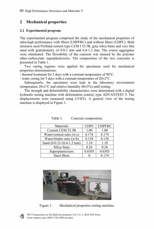
The experimental program comprised the study of the mechanical properties of ultra-high performance with fibers (UHPFRC) and without fibers (UHPC). Both mixtures used Portland cement type CEM I 52.5R, gray silica fume and very fine sand with granulometry of 0-0.3 mm and 0.4-1.2 mm. The coarse aggregates were eliminated. The flowability of the concrete was insured by the polymer ether-carboxylate superplasticizers. The composition of the two concretes is presented in Table 1. Two curing regimes were applied for specimens used for mechanical properties determinations: - thermal treatment for 5 days with a constant temperature of 90°C. - water curing for 5 days with a constant temperature of 20±2°C. Subsequently, the specimens were kept in the laboratory environment (temperature 20±2°C and relative humidity 60±5%) until testing. The strength and deformability characteristics were determined with a digital hydraulic testing machine with deformation control, type ADVANTEST 9. The displacements were measured using LVDTs. A general view of the testing machine is displayed in Figure 1.
Table 1: Concrete composition.
Materials UHPC UHPFRC Cement CEM 52.5R 1.00 1.00
Water/cement ratio (w/c) 0.174 0.174 Water/binder ratio (w/b) 0.138 0.138
Sand (0-0.3)+(0.4-1.2 mm) 1.18 1.18 Silica fume 0.26 0.26
Superplasticizers 0.0305 0.0305 Steel fibers 0 0.174
Figure 1: Mechanical properties testing machine.
www.witpress.com, ISSN 1743-3509 (on-line) WIT Transactions on The Built Environment, Vol 112, © 2010 WIT Press
80 High Performance Structures and Materials V
2.2 Fresh concrete properties
The flowability of the concrete was investigated with the slump flow test conducted immediately after the mixing process ended. It was observed that the steel fibers incorporation does not have a major influence on the concrete flowability, the slump flow measurement being about 120 mm. The water/cement ratio was 0.174. All specimens were produced from the same batch in order to eliminate the influence of the mixing condition. The specimens had the following geometry: 70x70x70mm and 100x100x100 mm cubes, 40x40x160mm and 100x100x300mm prisms. The specimens were demolded 24h after casting.
2.3 Compressive and splitting tensile strength
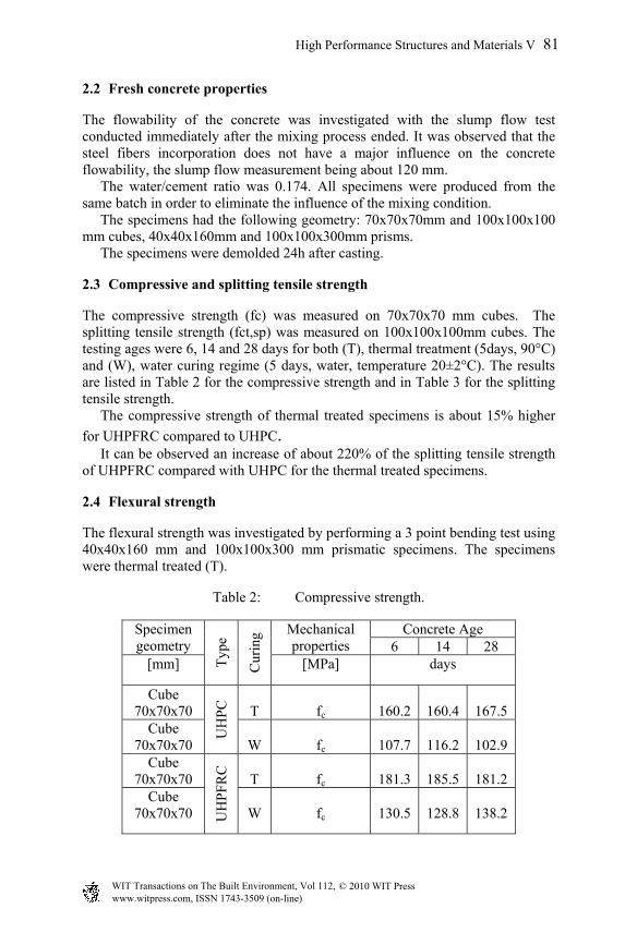
The compressive strength (fc) was measured on 70x70x70 mm cubes. The splitting tensile strength (fct,sp) was measured on 100x100x100mm cubes. The testing ages were 6, 14 and 28 days for both (T), thermal treatment (5days, 90°C) and (W), water curing regime (5 days, water, temperature 20±2°C). The results are listed in Table 2 for the compressive strength and in Table 3 for the splitting tensile strength. The compressive strength of thermal treated specimens is about 15% higher
for UHPFRC compared to UHPC. It can be observed an increase of about 220% of the splitting tensile strength of UHPFRC compared with UHPC for the thermal treated specimens.
2.4 Flexural strength
The flexural strength was investigated by performing a 3 point bending test using 40x40x160 mm and 100x100x300 mm prismatic specimens. The specimens were thermal treated (T).
Table 2: Compressive strength.
Specimen geometry
Typ
e
Cur
ing Mechanical
properties Concrete Age
6 14 28 [mm] [MPa] days
Cube 70x70x70
UH
PC
T
fc
160.2
160.4
167.5
Cube 70x70x70
W
fc
107.7
116.2
102.9
Cube 70x70x70
UH
PF
RC
T
fc
181.3
185.5
181.2
Cube 70x70x70
W
fc
130.5
128.8
138.2
www.witpress.com, ISSN 1743-3509 (on-line) WIT Transactions on The Built Environment, Vol 112, © 2010 WIT Press
High Performance Structures and Materials V 81

Table 3: Splitting tensile strength.
Specimen geometry
Typ
e
Cur
ing Mechanical properties Concrete Age
6 14 28 [mm] [MPa] days
Cube 100x100x100
UH
PC
T
fct,sp
7.9
9.2
9.4
Cube 100x100x100 W
fct,sp
5.8
7.7
6.9
Cube 100x100x100 U
HP
FR
C
T
fct,sp
17.5
20.2
20.4
Cube 100x100x100 W
fct,sp
6.6
7.8
12.6
Table 4: Flexural strength.
Specimen geometry
Typ
e
Cur
ing Mechanical
properties Concrete Age
6 14 28 [mm] [MPa] days
Prism 40x40x160
UH
PC
T
fct,fl
13.4
13.8
14.8
Prism 100x100x300
T
fct,fl
6.05
6.78
7.02
Prism 40x40x160
UH
PF
RC
T
fct,fl
21.8
23.1
22.30
Prism 100x100x300
T
fct,fl
11.5
12.7
16.6
(a) (b)
Figure 2: (a) Flexure failure of UHPFRC; (b) flexure failure of UHPC.
The testing procedures using ADVANTEST9 testing machine and the failure of the specimens are illustrated in Figure 2. Fiber reinforced concrete (UHPFRC) showed a flexural strength 150-165% higher than un-reinforced concrete (UHPC). The geometry of the specimens influenced the flexural strength, smaller specimens exhibiting a higher strength, as seen in Table 4.
www.witpress.com, ISSN 1743-3509 (on-line) WIT Transactions on The Built Environment, Vol 112, © 2010 WIT Press
82 High Performance Structures and Materials V

Figure 3: Load P(kN) vs. mid span deflection Δ (µm) curve (UHPFRC).
Figure 4: Load P(kN) vs. mid span deflection Δ (µm) curve (UHPC).
The flexural behavior of the two types of concrete can be observed by analyzing the load-deflection curves in Figures 3 and 4. UHPFRC displayed a ductile behavior. The middle span deflection at maximum load, as well as the ultimate middle span deflection, is about three times higher for UHPFRC compared to UHPC (900μm compared to 300μm). The peak load of UHPFRC was 1.5 times higher than the peak load of UHPC.
3 Bending and shear behavior of UHPC beams
3.1 Experimental program
The bending and shear behavior was tested on four I-shaped beams with identical cross sections.
Macro-crack localization
Strain-hardening (micro-cracks)
Linear-elastic
behavior (P<0.9Pmax) (microcracks)
Strain-softening (ductile failure)
Δ (µm)
P(kN)
Linear-elastic
behavior (P=Pmax) (microcracks)
Macro-crack localization (brittle failure)
Δ (µm)
P (kN)
www.witpress.com, ISSN 1743-3509 (on-line) WIT Transactions on The Built Environment, Vol 112, © 2010 WIT Press
High Performance Structures and Materials V 83

The bending beams had a total length of 3.2 m with a span of 3 mm. The shear beams had a total length of 1.67m and a span of 1.5m. The beams are described in Table 5. Beams’ reinforcement and geometry are described in Figures 5, 6, 7, and 8. The beams were demolded after 24h and afterwards were subject to thermal treatment for 5 days with a constant temperature of 90°C and a relative humidity of 40%.
Table 5: Beam description.
Beam types Load Bending Shear Without fibers TS1 TS2 With fibers TSF1 TSF2
Figure 5: TSF1 reinforcement and geometry.
Figure 6: TS1 reinforcement and geometry.
www.witpress.com, ISSN 1743-3509 (on-line) WIT Transactions on The Built Environment, Vol 112, © 2010 WIT Press
84 High Performance Structures and Materials V

Figure 7: TS2 reinforcement and geometry.
Figure 8: TSF2 reinforcement and geometry.
3.2 Testing procedure
The beams’ age was 28 days when tested. Tested beams’ measurement included: -displacements measured in 5 sections for bending and 3 sections for shear with 0.1mm precision; -middle span displacement with transducers with 0.03mm precision -cracks width by 0.1mm precision apparatus -cracks distance Aspects regarding test setups are displayed in Figure 9.
3.3 Tests results
3.3.1 Bending The results are plotted in Table 6 and the following observations can be made:
a) Bending beam with re-bars only: -maximum crack width Wmax
cr=0.1mm
-maximum displacement for the serviceability limit state (l/250) was recorded for M/Mu=0.57
b) Bending beam with re-bars and steel fibers: -maximum crack width Wmax
cr=0.1mm
www.witpress.com, ISSN 1743-3509 (on-line) WIT Transactions on The Built Environment, Vol 112, © 2010 WIT Press
High Performance Structures and Materials V 85

-maximum displacement for the serviceability limit state (l/250) was recorded for M/Mu=0.46
The bending moments ratio of the two beams for a crack widthWcrmax=0.1mm
is MTS10.1/ MTSF1
0.1=0.62. The fiber addition almost doubles the maximum bending moment, as expressed by the moment ratio of the two beams MTS1
0.1/ MTSF1
0.1=1.87. The ultimate strain in compression for the beam with fiber addition is 3.14 times higher than that of the beam without fibers. Load-mid span displacement curves can be analyzed in Figure 10. The failure of the beams is presented in Figure 11.
3.3.2 Shear Tests results are plotted in Table 7. A maximum inclined crack of 0.1mm is produced for a load ratio P/ Pu=0.2 in the stirrups reinforced beam (1 leg
(a) (b)
Figure 9: (a) Bending setup test; (b) shear setup test.
Table 6: Bending tests results.
Beam M M/Mu Wcr
max Δ εcmax
Notes kNm [mm] [mm] [%0]
TS1 no
fibers
10 0.57 0.1 7.9 (l/250) 0.75 M=bending moment Mu=maximum bending moment Wcr
max=maximum crack width Δ=middle span displacement εc
max=ultimate strain (compression) l= beam span
12.5 0.71 0.2 8.2 (l/190) 1.05 15 0.86 0.5 12.5 (l/160) 1.50
17.5 1.00 - 14.5 (l/70) 1.75
TSF1 with fibers
13.7 0.39 0.05 9 (l/333) 0.87 16.1 0.49 0.1 15.2 (l/200) 1.05 23 0.70 0.2 22.1 (l/135) 1.50
27.5 0.87 0.3 26.8 (l/111) 2.05 32.73 1.00 - 71.0 (l/42) 5.50
www.witpress.com, ISSN 1743-3509 (on-line) WIT Transactions on The Built Environment, Vol 112, © 2010 WIT Press
86 High Performance Structures and Materials V

Figure 10: Load-mid span deflection, bending testing.
Table 7: Shear tests results.
Beam P P/Pu Wcr
max Notes
kN [mm]
TS2 no
fibers
25.00 0.20 0.1 P=force Pmax=maximum force Wcr
max=maximum inclined crack width a/d=1 (shear slenderness ratio) PF
0,1/ PFF
0,1=3.2 PF
u/ PFF
u=2.04
39.00 0.32 0.2 55.00 0.45 0.3 60.00 0.49 0.4 122.40 1.00 -
TSF2 with fibers
80.00 0.32 0.1 142.00 0.56 0.2 178.00 0.71 0.3 188.00 0.75 0.5 250.00 1.00 -
(a) (b)
Figure 11: (a) Failure of TSF1; (b) failure of TS1
Figure 12: Load-mid span deflection, shear testing.
TFS1
TS1
TFS2
TS2
www.witpress.com, ISSN 1743-3509 (on-line) WIT Transactions on The Built Environment, Vol 112, © 2010 WIT Press
High Performance Structures and Materials V 87

(a) (b)
Figure 13: (a) Failure of TS2; (b) failure of TSF2.
10mm, s=100mm, steel Bst500S). The same crack opening of 0.1mm is produced at P/ Pu=0.32 for the steel fiber reinforced beam (without stirrups). By adding fiber in concrete composition the rupture force is 2.04 times higher than for concrete without fibers. Load-mid span deflection curves are displayed in Figure 12. The failure of the beams is presented in Figure 13.
4 Conclusions
The paper presents the mechanical properties of ultra high performance concrete. The influence of steel fiber reinforcement, age, geometry of the specimens and environmental conditions was evaluated. Fiber reinforcement influence was analyzed in terms of mechanical properties and behavior of concrete beams in shear and bending. Thermal treatment improved mechanical strengths. Fiber addition improved the compressive strengths, but the most significant influence was on the tensile strengths and on the element behavior. Smaller specimens exhibited higher flexural strength. Splitting tensile strength of UHPFRC is about 2.2 times higher than that of UHPC. It was observed a ductile post peak behavior for UHPFRC with 2% steel fibers by concrete volume. For about 85-95% of the peak load, UHPC and UHPFRC displayed a quasi-linear behavior when tested in flexure. Regarding shear and bending tests on beams, the steel fibers addition improved the behavior and loading capacity for the tested beams. The tests suggested that fiber reinforcement is extremely efficient and can successfully replace steel stirrups. This aspect is very important for both time and money saving. Moreover, ultra high performance concrete requires small cross sections and, bearing in mind the compressive strength of this concrete, it is quite impossible to use only stirrups as shear reinforcement.
Acknowledgements
This research was conducted within a PCE-PN II-IDEI Program, code 1053/2007, financed by National Scientific Research Council for Higher
www.witpress.com, ISSN 1743-3509 (on-line) WIT Transactions on The Built Environment, Vol 112, © 2010 WIT Press
88 High Performance Structures and Materials V

Education (CNCSIS), Romania. The authors would like to express their gratitude to CNCSIS.
References
[1] Rossi P. (2001) Ultra-High-Performance Fiber-Reinforced Concrete-A French Perspective on approaches used to produce high-strength, ductile fiber reinforced concrete, Concrete International, December, 46-52
[2] Magureanu C., Sosa I. (2008) Ultra High Performance Concrete. Reinforced and Prestressed concrete Structures Roads. Bridges and railways. Proceedings of the International Conference: Construction 2008, Cluj-Napoca. 127-132.
[3] Magureanu C., Heghes B., Corbu O, Szilagy H., Sosa I. (2008) Behavior of High and Ultra High Fiber Reinforced Concrete. 8th International Symposium on Utilization of High-Strength and High-Performance Concrete, Tokyo. 353-356.
[4] Magureanu C., Heghes B., Negrutiu C. (2009) Ultra High Performance Concrete with and without steel fiber. Concrete 21 Century Super Hero, London.
[5] Benjamin A. Graybeal, (2007) Compressive behavior of Ultra High Performance Fiber-Reinforced Concrete. ACI Materials Journal, March-April, 316-319.
[6] Sugamata T., Sugiyama T, Okazawa S. (2002) Study on the fresh and hardened properties of concrete containing superplasticizers for Ultra High Strength Concrete, Proceedings of the 1st fib Congress, Session 9, 87-96.
www.witpress.com, ISSN 1743-3509 (on-line) WIT Transactions on The Built Environment, Vol 112, © 2010 WIT Press
High Performance Structures and Materials V 89