belt conveyor guf-p 2000 - conveyor manufacturer
TRANSCRIPT
36
22
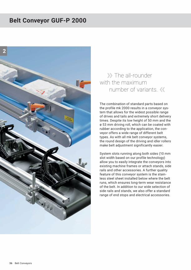
The combination of standard parts based on the profile mk 2000 results in a conveyor sys-tem that allows for the widest possible range of drives and tails and extremely short delivery times. Despite its low height of 50 mm and the ø 53 mm driving roll, which can be coated with rubber according to the application, the con-veyor offers a wide range of different belt types. As with all mk belt conveyor systems, the round design of the driving and idler rollers make belt adjustment significantly easier.
System slots running along both sides (10 mm slot width based on our profile technology) allow you to easily integrate the conveyors into existing machine frames or attach stands, side rails and other accessories. A further quality feature of this conveyor system is the stain-less steel sheet installed below where the belt runs, which ensures long-term wear resistance of the belt. In addition to our wide selection of side rails and stands, we also offer a standard range of end stops and electrical accessories.
Belt Conveyor GUF-P 2000
» The all-rounder with the maximum number of variants. «
Belt Conveyors
37
2
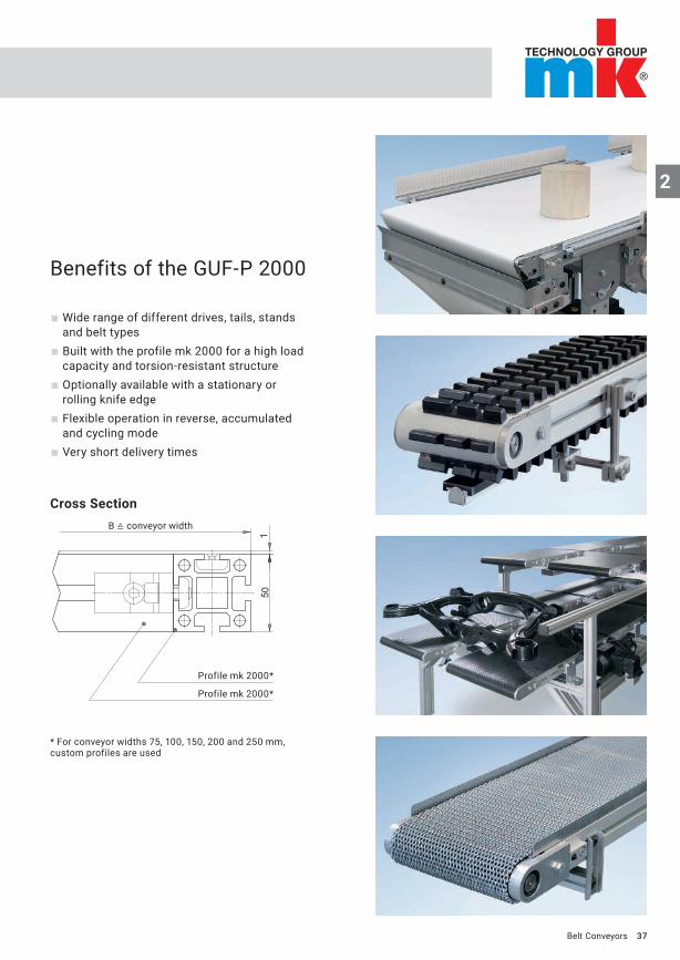
Profile mk 2000*
Profile mk 2000*
Cross Section
Benefits of the GUF-P 2000
Wide range of different drives, tails, stands and belt types
Built with the profile mk 2000 for a high load capacity and torsion-resistant structure
Optionally available with a stationary or rolling knife edge
Flexible operation in reverse, accumulated and cycling mode
Very short delivery times
Belt Conveyors
* For conveyor widths 75, 100, 150, 200 and 250 mm, custom profiles are used
B ≙ conveyor width
38
2
20/2
9
L
B
B+10
B
ø 53
ø 16
ø 53
GUF-P 2000 AA
Belt Conveyors
PropertiesThe drive variant AA without a motor offers the advantage of operating multiple conveyor belts in parallel or in series with one drive. The compact conveyor frame design makes it easier to integrate the conveyor into existing systems. The driving roll ø 53 mm has a round design for simple belt control. Operation with cleated belts is possible with this version. The ø 16 mm shaft journal has a usable length of 20 mm with a chain drive or 29 mm with a timing belt drive and is equipped with a DIN 6885 key.
B20.00.009
Technical dataConveyor length L individual from 380 to 10000 mm
Conveyor width B 50, 75, 100, 150, 200, 250, 300, 400, 500, 600, 700, 800 mm others on request
Belt width B-10 mm from p. 88
Drive and speed up to v=80 m/min p. 12
Stand and side rail from p. 280
Standard total load up to 75 kg p. 20
Standard distributed load up to 25 kg/m p. 20
Tails from page 49
ø 19/ø12 rolling
ø10 sliding
39
2
ø 53ø 53 B
144B
B+11L
250
36
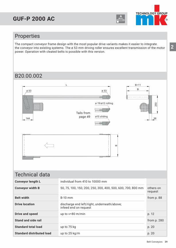
GUF-P 2000 AC
Belt Conveyors
PropertiesThe compact conveyor frame design with the most popular drive variants makes it easier to integrate the conveyor into existing systems. The ø 53 mm driving roller ensures excellent transmission of the motor power. Operation with cleated belts is possible with this version.
B20.00.002
Technical dataConveyor length L individual from 410 to 10000 mm
Conveyor width B 50, 75, 100, 150, 200, 250, 300, 400, 500, 600, 700, 800 mm others on request
Belt width B-10 mm from p. 88
Drive location discharge end left/right, underneath/above; infeed end on request
Drive and speed up to v=80 m/min p. 12
Stand and side rail from p. 280
Standard total load up to 75 kg p. 20
Standard distributed load up to 25 kg/m p. 20
Tails from page 49
ø 19/ø12 rolling
ø10 sliding

40
2
ø 53 ø 53
L
B
B+10
B
GUF-P 2000 AF
Tails from page 49
ø 19/ø12 rolling
ø10 sliding
Belt Conveyors
PropertiesSince the motor is fitted directly onto the drive shaft, the space requirements and maintenance effort for this drive version are reduced to a minimum.
B20.00.011
Technical dataConveyor length L individual from 410 to 10000 mm
Conveyor width B 50, 75, 100, 150, 200, 250, 300, 400, 500, 600, 700, 800 mm others on request
Belt width B-10 mm from p. 88
Drive location discharge end left/right; infeed end on request
Drive and speed 2.8; 3.7; 4.5; 5.5; 6.7; 7.9; 8.9; 11.2; 13.2 and 15.2 m/min p. 12
Stand and side rail from p. 280
Standard total load up to 30 kg p. 20
Standard distributed load up to 25 kg/m p. 20

41
2
ø 53 ø 53
B
B
B+11
175
36
L
104
GUF-P 2000 AG
Tails from page 49
ø 19/ø12 rolling
ø10 sliding
Belt Conveyors
PropertiesThe compact drive version AG for small gearmotors (direct current or three-phase motors) has fewer inter-fering edges in comparison to the AC drive version thanks to the gearbox type used. The compact conveyor frame design makes it easier to integrate the conveyor into existing systems. Without a snub roller, the ø 53 mm driving roller enables the use of cleated belts. In comparison to the drive version AC, the dimensi-ons of the drive are much more compact.
B20.00.005
Technical dataConveyor length L individual from 380 to 6000 mm
Conveyor width B 50, 75, 100, 150, 200, 250, 300, 400, 500, 600, 700, 800 mm others on request
Belt width B-10 mm from p. 88
Drive location discharge end left/right, underneath/above
Drive and speed up to v=15 m/min p. 12
Stand and side rail from p. 280
Standard total load up to 30 kg AC/15 kg DC p. 20
Standard distributed load up to 25 kg/m p. 20
42
2
ø 53 ø 53
144325
B
L
B
B+10
250
36
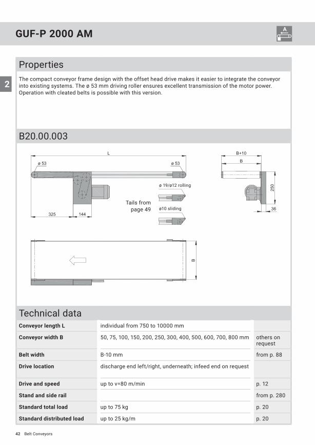
GUF-P 2000 AM
Tails from page 49
ø 19/ø12 rolling
ø10 sliding
Belt Conveyors
PropertiesThe compact conveyor frame design with the offset head drive makes it easier to integrate the conveyor into existing systems. The ø 53 mm driving roller ensures excellent transmission of the motor power. Operation with cleated belts is possible with this version.
B20.00.003
Technical dataConveyor length L individual from 750 to 10000 mm
Conveyor width B 50, 75, 100, 150, 200, 250, 300, 400, 500, 600, 700, 800 mm others on request
Belt width B-10 mm from p. 88
Drive location discharge end left/right, underneath; infeed end on request
Drive and speed up to v=80 m/min p. 12
Stand and side rail from p. 280
Standard total load up to 75 kg p. 20
Standard distributed load up to 25 kg/m p. 20

43
2
ø 53 ø 53
B
L
260
130
64
B
B+10
GUF-P 2000 AS
Tails from page 49
ø 19/ø12 rolling
ø10 sliding
Belt Conveyors
PropertiesThe drive located laterally on the outside allows the total height of the conveyor to be restricted to a minimum. The ø 53 mm driving roller ensures excellent transmission of the motor power. Operation with cleated belts is possible with this version.
B20.00.008
Technical dataConveyor length L individual from 550 to 10000 mm
Conveyor width B 50, 75, 100, 150, 200, 250, 300, 400, 500, 600, 700, 800 mm others on request
Belt width B-10 mm from p. 88
Drive location discharge end left/right; infeed end on request
Drive and speed up to v=80 m/min p. 12
Stand and side rail from p. 280
Standard total load up to 75 kg p. 20
Standard distributed load up to 25 kg/m p. 20
44
2
ø 53ø 53
150B
B+11
47
200
L
B
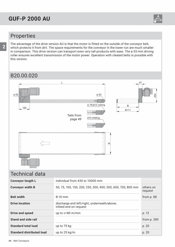
GUF-P 2000 AU
Tails from page 49
ø 19/ø12 rolling
ø10 sliding
Belt Conveyors
PropertiesThe advantage of the drive version AU is that the motor is fitted on the outside of the conveyor belt, which protects it from dirt. The space requirements for the conveyor in the lower run are much smaller in com parison. This drive version can transport even very tall products with ease. The ø 53 mm driving roller ensures excellent transmission of the motor power. Operation with cleated belts is possible with this version.
B20.00.020
Technical dataConveyor length L individual from 430 to 10000 mm
Conveyor width B 50, 75, 100, 150, 200, 250, 300, 400, 500, 600, 700, 800 mm others on request
Belt width B-10 mm from p. 88
Drive location discharge end left/right, underneath/above; infeed end on request
Drive and speed up to v=80 m/min p. 12
Stand and side rail from p. 280
Standard total load up to 75 kg p. 20
Standard distributed load up to 25 kg/m p. 20

45
2
ø 53 ø 53 B
B+12
189
L
B
200L2
B+30
ø 62/ø 88
� 20
GUF-P 2000 BA
Tails from page 49
ø 19/ø12 rollingø 19/ø12 rolling
ø10 slidingø10 sliding
Belt Conveyors
PropertiesThe drive variant BA without a motor provides the advantage of operating multiple conveyor belts in paral-lel with one drive. The compact conveyor frame design and the ability to freely select the drive position over the entire length of the conveyor make it easier to integrate the conveyor into existing systems. The conveying direction is reversible. Knife edges can be configured on both the infeed and discharge end. Operation with cleated belts is not possible with this version. The driving roller has a hollow shaft design with ø 20 mm with keyway in accordance with DIN 6885.
B20.00.001
Technical dataConveyor length L individual from 700 to 10000 mm
Conveyor width B 50, 75, 100, 150, 200, 250, 300, 400, 500, 600, 700, 800 mm others on request
Belt width B-10 mm from p. 88
Drive and speed up to v=80 m/min p. 12
Stand and side rail from p. 280
Standard total load up to 75 kg p. 20
Standard distributed load up to 25 kg/m p. 20

46
2
ø 53 ø 53
100
200L2
L
B
B+12
189
36
235
8
326
B
ø 62/ø 88
GUF-P 2000 BC
Tails from page 49
ø 19/ø12 rollingø 19/ø12 rolling
ø10 slidingø10 sliding
Belt Conveyors
PropertiesThe compact conveyor frame design and the ability to freely select the drive position over the entire length of the conveyor make it easier to integrate the conveyor into existing systems. The conveying direction is reversible. Knife edges can be configured on both the infeed and discharge end. Operation with cleated belts is not possible with this version.
B20.00.004
Technical dataConveyor length L individual from 700 to 10000 mm
Conveyor width B 50, 75, 100, 150, 200, 250, 300, 400, 500, 600, 700, 800 mm others on request
Belt width B-10 mm from p. 88
Drive location left/right underneath
Drive and speed up to v=80 m/min p. 12
Stand and side rail from p. 280
Standard total load up to 75 kg p. 20
Standard distributed load up to 25 kg/m p. 20

47
2
ø 53 ø 53 B
B+12
189
L
B
L2 200
ø 62/ø 88
GUF-P 2000 BF
ø 19/ø12 rollingø 19/ø12 rolling
ø10 slidingø10 sliding
Tails from page 49
Belt Conveyors
PropertiesSince the motor is fitted directly onto the drive shaft, the space requirements and maintenance effort for this drive version are reduced to a minimum. The compact conveyor frame design and the ability to freely select the drive position over the entire length of the conveyor make it easier to integrate the conveyor into existing systems. The conveying direction is reversible. Knife edges can be configured on both the infeed and discharge end. Operation with cleated belts is not possible with this version.
B20.00.012
Technical dataConveyor length L individual from 700 to 10000 mm
Conveyor width B 50, 75, 100, 150, 200, 250, 300, 400, 500, 600, 700, 800 mm others on request
Belt width B-10 mm from p. 88
Drive location left/right underneath
Drive and speed 5; 6.3; 8; 9.5; 11.5; 13.5; 15.2; 19.3; 23; 26; 36.6; 45.7 and 57 m/min
p. 12
Stand and side rail from p. 280
Standard total load up to 75 kg p. 20
Standard distributed load up to 25 kg/m p. 20
48
2
ø 53ø 81,5
L
B
B+52,5
B
100
B+27
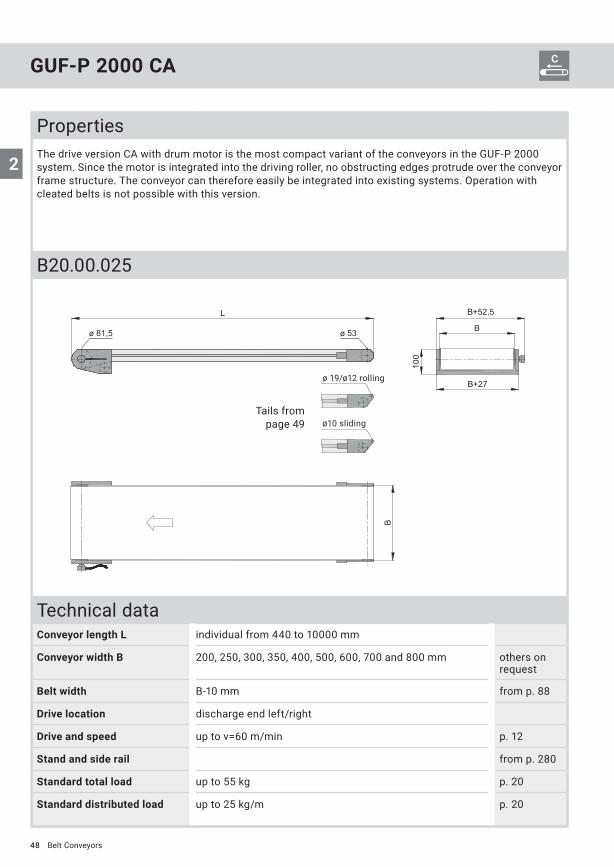
GUF-P 2000 CA
Belt Conveyors
PropertiesThe drive version CA with drum motor is the most compact variant of the conveyors in the GUF-P 2000 system. Since the motor is integrated into the driving roller, no obstructing edges protrude over the conveyor frame structure. The conveyor can therefore easily be integrated into existing systems. Operation with cleated belts is not possible with this version.
B20.00.025
Technical dataConveyor length L individual from 440 to 10000 mm
Conveyor width B 200, 250, 300, 350, 400, 500, 600, 700 and 800 mm others on request
Belt width B-10 mm from p. 88
Drive location discharge end left/right
Drive and speed up to v=60 m/min p. 12
Stand and side rail from p. 280
Standard total load up to 55 kg p. 20
Standard distributed load up to 25 kg/m p. 20
Tails from page 49
ø 19/ø12 rolling
ø10 sliding

49
2
ø 53
ø 53
ø 53
114
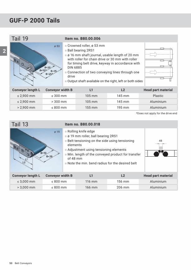
GUF-P 2000 Tails
Tail 01 Item no. B80.00.001
Crowned roller, ø 53 mm Ball bearing 2RS1 Belt tensioning and adjustment on the side using the tensioning elements
Min. length of the conveyed product for transfer of 114 mm
Tail 09 Item no. B80.00.005
Crowned roller, ø 53 mm Ball bearing 2RS1 Belt tensioning via head parts Belt adjustment from the front using threaded pins
Obstructing edge-optimised tail Min. length of the conveyed product for transfer of 114 mm
Tail 11 Item no. B80.00.007
Crowned roller, ø 53 mm Ball bearing 2RS1 Belt tensioning and adjustment on the side using the head parts (approx. 35 mm of clearance required on each side)
Flush head parts Obstructing edge-optimised tail Min. length of the conveyed product for transfer of 114 mm
Conveyor length L Conveyor width B L1 L2 Head part material
≤ 2,900 mm ≤ 300 mm 105 mm 145 mm Plastic
≤ 2,900 mm > 300 mm 105 mm 145 mm Aluminium
> 2,900 mm ≤ 800 mm 155 mm 195 mm Aluminium
Conveyor length L Conveyor width B L1 L2 Head part material
≤ 3,000 mm ≤ 800 mm 105 mm — Aluminium
Conveyor length L Conveyor width B L1 L2 Head part material
≤ 3,000 mm ≤ 800 mm 105 mm — Aluminium
Belt Conveyors
50
2ø 53
ø 19
48
GUF-P 2000 Tails
*Does not apply for the drive end
Tail 19 Item no. B80.00.006
Crowned roller, ø 53 mm Ball bearing 2RS1 ø 16 mm shaft journal, usable length of 20 mm with roller for chain drive or 30 mm with roller for timing belt drive, keyway in accordance with DIN 6885
Connection of two conveying lines through one drive
Output shaft available on the right, left or both sides
Tail 13 Item no. B80.00.018
Rolling knife edge ø 19 mm roller, ball bearing 2RS1 Belt tensioning on the side using tensioning elements
Adjustment using tensioning elements Min. length of the conveyed product for transfer of 48 mm
Note the min. bend radius for the desired belt
Conveyor length L Conveyor width B L1 L2 Head part material
≤ 2,900 mm ≤ 300 mm 105 mm 145 mm Plastic
≤ 2,900 mm > 300 mm 105 mm 145 mm Aluminium
> 2,900 mm ≤ 800 mm 155 mm 195 mm Aluminium
Conveyor length L Conveyor width B L1 L2 Head part material
≤ 3,000 mm ≤ 800 mm 116 mm 156 mm Aluminium
> 3,000 mm ≤ 800 mm 166 mm 206 mm Aluminium
Belt Conveyors

51
2
ø 10
ø 12
34
30
Tail 10 Item no. B80.00.017
Rolling knife edge ø 12 mm roller, ball bearing 2RS1 Belt tensioning on the side using tensioning elements
Adjustment from the front using tensioning roller Min. length of the conveyed product for transfer of 34 mm
Note the min. bend radius for the desired belt Max. conveying speed of 30 m/min Max. load capacity of 5 kg per 50 mm conveyor width
Tail 17 Item no. B80.00.002
Stationary knife edge Belt tensioning on the side using tensioning elements
Adjustment from the front using tensioning roller Min. length of the conveyed product for transfer of 30 mm
Note the min. bend radius for the desired belt Max. conveying speed of 10 m/min Requires driving roller with rubber coating
Conveyor length L Conveyor width B L1 L2 Head part material
≤ 3,000 mm ≤ 300 mm 111 mm 151 mm Aluminium
> 3,000 mm ≤ 300 mm 161 mm 201 mm Aluminium
Conveyor length L Conveyor width B L1 L2 Head part material
≤ 3,000 mm ≤ 300 mm 105 mm 145 mm Aluminium
Belt Conveyors
88
2
Belts
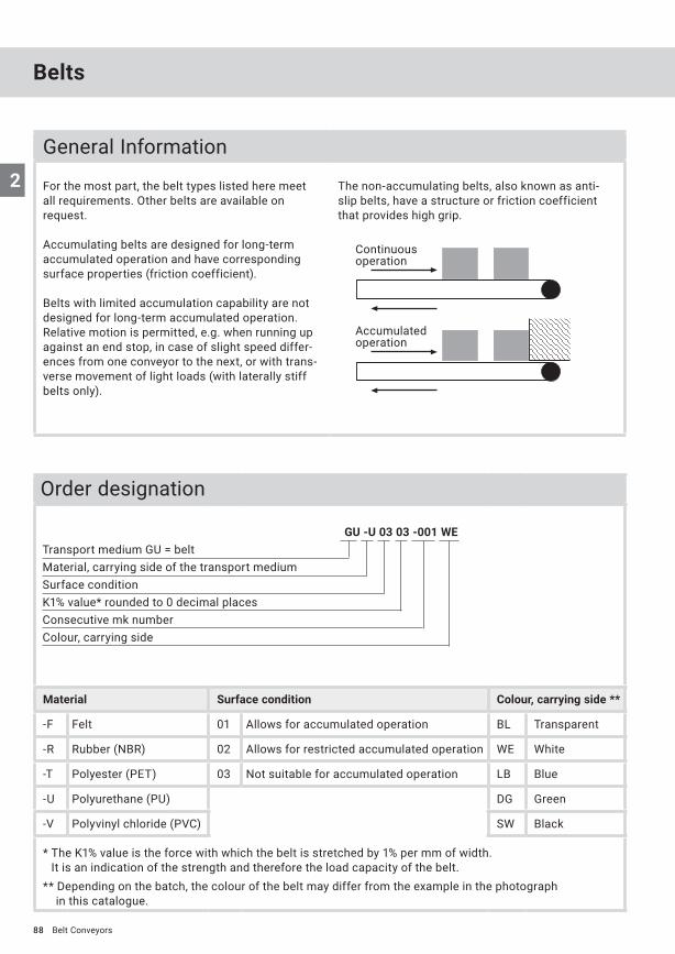
GU -U 03 03 -001 WETransport medium GU = beltMaterial, carrying side of the transport mediumSurface conditionK1% value* rounded to 0 decimal placesConsecutive mk numberColour, carrying side
Order designation
Material Surface condition Colour, carrying side **
-F Felt 01 Allows for accumulated operation BL Transparent
-R Rubber (NBR) 02 Allows for restricted accumulated operation WE White
-T Polyester (PET) 03 Not suitable for accumulated operation LB Blue
-U Polyurethane (PU) DG Green
-V Polyvinyl chloride (PVC) SW Black
* The K1% value is the force with which the belt is stretched by 1% per mm of width. It is an indication of the strength and therefore the load capacity of the belt.
** Depending on the batch, the colour of the belt may differ from the example in the photograph in this catalogue.
Belt Conveyors
General Information
For the most part, the belt types listed here meet all requirements. Other belts are available on request.
Accumulating belts are designed for long-term accumulated operation and have corresponding surface properties (friction coefficient).
Belts with limited accumulation capability are not designed for long-term accumulated operation. Relative motion is permitted, e.g. when running up against an end stop, in case of slight speed differ-ences from one conveyor to the next, or with trans-verse movement of light loads (with laterally stiff belts only).
The non-accumulating belts, also known as anti-slip belts, have a structure or friction coefficient that provides high grip.
Continuous operation
Accumulated operation
89
2
Belts
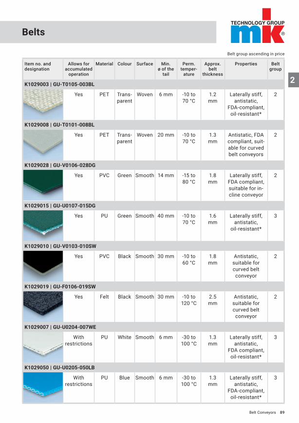
Item no. and designation
Allows for accumulated
operation
Material Colour Surface Min. ø of the
tail
Perm. temper-
ature
Approx. belt
thickness
Properties Belt group
K1029003 | GU-T0105-003BL
Yes PET Trans-parent
Woven 6 mm -10 to 70 °C
1.2 mm
Laterally stiff, antistatic,
FDA-compliant,oil-resistant*
2
K1029008 | GU-T0101-008BL
Yes PET Trans-parent
Woven 20 mm -10 to 70 °C
1.3 mm
Antistatic, FDA compliant, suit-able for curved belt conveyors
2
K1029028 | GU-V0106-028DG
Yes PVC Green Smooth 14 mm -15 to 80 °C
1.8 mm
Laterally stiff, FDA compliant, suitable for in- cline conveyor
2
K1029015 | GU-U0107-015DG
Yes PU Green Smooth 40 mm -10 to 70 °C
1.6 mm
Laterally stiff, antistatic,
oil-resistant*
3
K1029010 | GU-V0103-010SW
Yes PVC Black Smooth 30 mm -10 to 60 °C
1.8 mm
Antistatic, suitable for curved belt conveyor
2
K1029019 | GU-F0106-019SW
Yes Felt Black Smooth 30 mm -10 to 120 °C
2.5 mm
Antistatic, suitable for curved belt conveyor
2
K1029007 | GU-U0204-007WE
With restrictions
PU White Smooth 6 mm -30 to 100 °C
1.3 mm
Laterally stiff, antistatic,
FDA compliant, oil-resistant*
3
K1029050 | GU-U0205-050LB
With restrictions
PU Blue Smooth 6 mm -30 to 100 °C
1.3 mm
Laterally stiff, antistatic,
FDA-compliant,oil-resistant*
3
Belt Conveyors
Belt group ascending in price
90
2
Belt group ascending in price
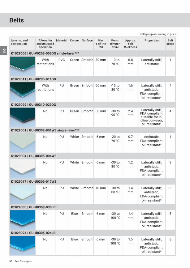
Item no. and designation
Allows for accumulated
operation
Material Colour Surface Min. ø of the
tail
Perm. temper-
ature
Approx. belt
thickness
Properties Belt group
K1029006 | GU-V0203-006DG single-layer***
With restrictions
PVC Green Smooth 30 mm -10 to 70 °C
0.8 mm
Laterally stiff, antistatic
1
K1029011 | GU-U0205-011DG
With restrictions
PU Green Smooth 50 mm -15 to 80 °C
1.6 mm
Laterally stiff, antistatic,
FDA-compliant,oil-resistant*
4
K1029029 | GU-U0310-029DG
No PU Green Smooth 50 mm -30 to 90 °C
2.4 mm
Laterally stiff, FDA compliant, suitable for in- cline conveyor,oil-resistant*
4
K1029001 | GU-U0302-001WE single-layer***
No PU White Smooth 6 mm -20 to 70 °C
0.7 mm
Antistatic, FDA-compliant,
oil-resistant*
1
K1029004 | GU-U0305-004WE
No PU White Smooth 6 mm -30 to 80 °C
1.2 mm
Laterally stiff, antistatic,
FDA-compliant,oil-resistant*
3
K1029017 | GU-U0306-017WE
No PU White Smooth 10 mm -30 to 80 °C
1.4 mm
Laterally stiff, antistatic,
FDA-compliant,oil-resistant*
3
K1029030 | GU-U0308-030LB
No PU Blue Smooth 6 mm -30 to 100 °C
1.4 mm
Laterally stiff, antistatic,
FDA-compliant,oil-resistant*
3
K1029024 | GU-U0305-024LB
No PU Blue Smooth 6 mm -30 to 100 °C
1.5 mm
Laterally stiff, antistatic,
FDA-compliant,oil-resistant*
3
Belts
Belt Conveyors

91
2
Belt group ascending in price
Item no. and designation
Allows for accumulated
operation
Material Colour Surface Min. ø of the
tail
Perm. temper-
ature
Approx. belt
thickness
Properties Belt group
K1029012 | GU-U0306-012DG
No PU Green Smooth 25 mm -30 to 100 °C
1.4 mm
Laterally stiff, antistatic,
FDA-compliant,oil-resistant*
3
K1029009 | GU-V0303-009DG
No PVC Green Smooth 25 mm -10 to 70 °C
1.8 mm
Antistatic, suitable for curved belt conveyor
2
K1029013 | GU-V0307-013DG
No PVC Green Smooth 40 mm -10 to 60 °C
2.0 mm
Laterally stiff, antistatic
2
K1029005 | GU-R0303-005DG
No NBR Green Woven 30 mm 0 to 80 °C
1.5 mm
Antistatic,oil-resistant*,
cut-proof
3
K1029016 | GU-U0305-016DG
No PU Green Structu-red
40 mm -30 to 80 °C
1.9 mm
Antistatic,oil-resistant*
4
K1029014 | GU-V0306-014DG
No PVC Green Structu-red
50 mm -10 to 60 °C
4.9 mm
Laterally stiff, antistatic
3
K1029018 | GU-V0307-018SW
No PVC Black Structu-red
40 mm -10 to 60 °C
2.2 mm
Laterally stiff, antistatic
2
* The belt’s oil resistance may need to be tested based on the type of oil used.** Cut-proof belts ensure a longer service life when transporting sharp products such as stamped parts.*** Single-layer belts are less robust and therefore must not be as strongly pre-tensioned.
Belts
Belt Conveyors
92
2
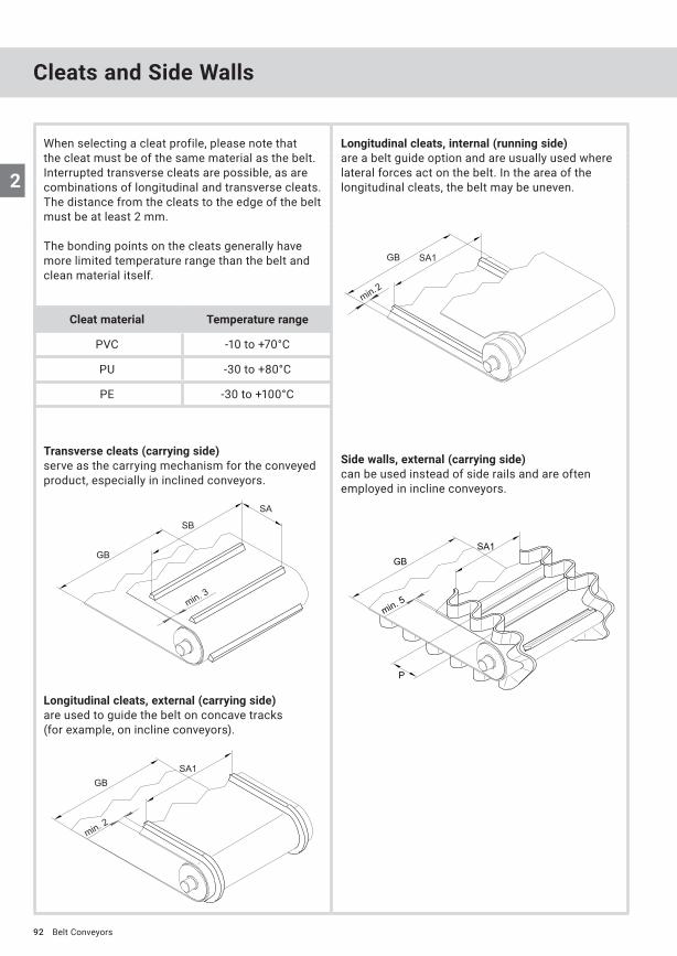
When selecting a cleat profile, please note that the cleat must be of the same material as the belt. Interrupted transverse cleats are possible, as are combinations of longitudinal and transverse cleats. The distance from the cleats to the edge of the belt must be at least 2 mm.
The bonding points on the cleats generally have more limited temperature range than the belt and clean material itself.
Longitudinal cleats, internal (running side)are a belt guide option and are usually used where lateral forces act on the belt. In the area of the longitudinal cleats, the belt may be uneven.
Longitudinal cleats, external (carrying side)are used to guide the belt on concave tracks (for example, on incline conveyors).
Side walls, external (carrying side)can be used instead of side rails and are often employed in incline conveyors.
Transverse cleats (carrying side)serve as the carrying mechanism for the conveyed product, especially in inclined conveyors.
Belt Conveyors
Cleats and Side Walls
Cleat material Temperature range
PVC -10 to +70°C
PU -30 to +80°C
PE -30 to +100°C
93
2
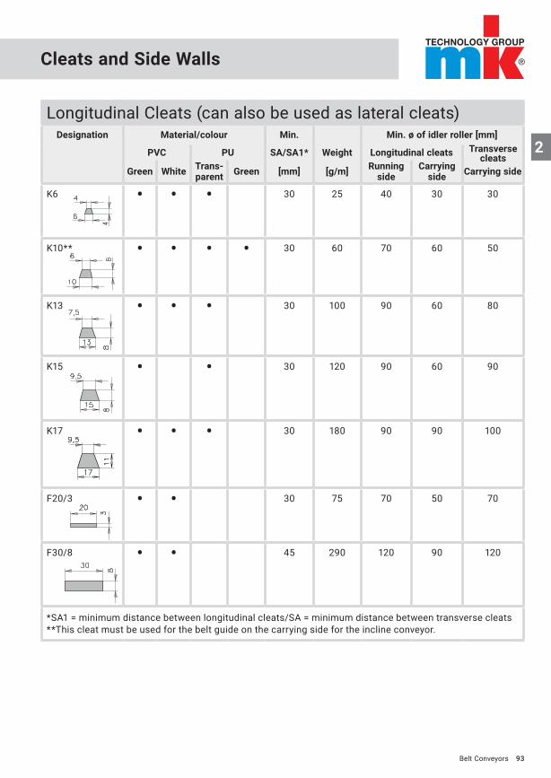
Longitudinal Cleats (can also be used as lateral cleats)Designation Material/colour Min. Min. ø of idler roller [mm]
PVC PU SA/SA1* Weight Longitudinal cleats
Green White Trans- parent Green [mm] [g/m] Running
side Carrying
side Carrying side
K6 • • • 30 25 40 30 30
K10** • • • • 30 60 70 60 50
K13 • • • 30 100 90 60 80
K15 • • 30 120 90 60 90
K17 • • • 30 180 90 90 100
F20/3 • • 30 75 70 50 70
F30/8 • • 45 290 120 90 120
*SA1 = minimum distance between longitudinal cleats/SA = minimum distance between transverse cleats**This cleat must be used for the belt guide on the carrying side for the incline conveyor.
Belt Conveyors
Cleats and Side Walls
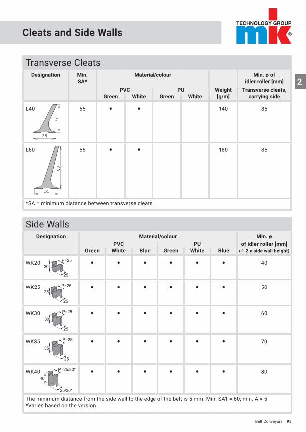
Transverse cleats

94
2
Cleats and Side Walls
Transverse CleatsDesignation Min.
SA*Material/colour Min. ø of
idler roller [mm]PVC PU Weight Transverse cleats
Green White Green White [g/m] carrying side
T20U 40 • • 140 50
T30U 40 • • 180 50
T35U 40 • • 200 50
T40U 40 • • 220 50
T50U 40 • • 250 50
T60U 40 • • 280 50
T20 55 • • 160 90
Belt Conveyors
95
2
P=25
25
20
25
P=2525
P=25
25
30
P=25
25
35
P=25/30*
25/36*
40
Cleats and Side Walls
Side WallsDesignation Material/colour Min. ø
PVC PU of idler roller [mm]Green White Blue Green White Blue (≙ 2 x side wall height)
WK20 • • • • • • 40
WK25 • • • • • • 50
WK30 • • • • • • 60
WK35 • • • • • • 70
WK40 • • • • • • 80
The minimum distance from the side wall to the edge of the belt is 5 mm. Min. SA1 = 60; min. A = 5*Varies based on the version
Transverse CleatsDesignation Min.
SA*Material/colour Min. ø of
idler roller [mm]PVC PU Weight Transverse cleats,
Green White Green White [g/m] carrying side
L40 55 • • 140 85
L60 55 • • 180 85
*SA = minimum distance between transverse cleats
Belt Conveyors
2
96
2
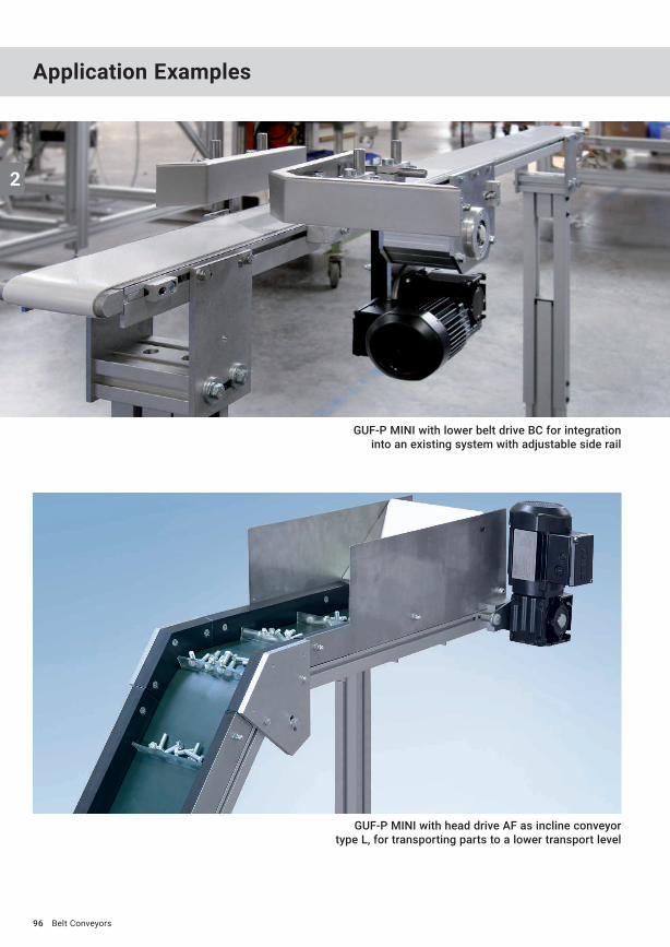
GUF-P MINI with lower belt drive BC for integration into an existing system with adjustable side rail
GUF-P MINI with head drive AF as incline conveyor type L, for transporting parts to a lower transport level
Belt Conveyors
Application Examples

2
97
GUF-P MINI with single-belt stand and drip pan below the motor for slightly oily stamped parts
GUF-P MINI with lower belt drive BC as inclined conveyor, stand system 53.12
GUF-P MINI with lower belt drive BC as special configuration with 5 conveying lines. The inner conveying lines can be moved manually and are guided by guide rods
Belt Conveyors

2
99
GUF-P 2000 as cross conveyor and separator downstream from a cooling line
GUF-P 2000 for connecting rods with pneumatic positioning station
GUF-P 2000 with mechanism for folding and setting up paper bags upstream of the filling process
Belt Conveyors
2
100
2
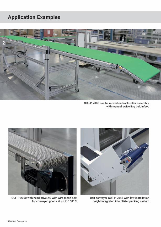
GUF-P 2000 can be moved on track roller assembly, with manual swivelling belt infeed
Belt conveyor GUF-P 2045 with low installation height integrated into blister packing system
GUF-P 2000 with head drive AC with wire mesh belt for conveyed goods at up to 150° C
Belt Conveyors
Application Examples
2
101
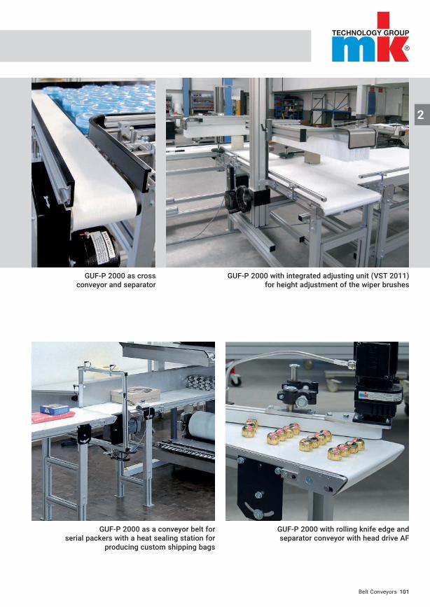
GUF-P 2000 as cross conveyor and separator
GUF-P 2000 as a conveyor belt for serial packers with a heat sealing station for
producing custom shipping bags
GUF-P 2000 with integrated adjusting unit (VST 2011) for height adjustment of the wiper brushes
GUF-P 2000 with rolling knife edge and separator conveyor with head drive AF
Belt Conveyors
2
104
2
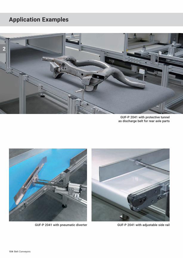
GUF-P 2041 with pneumatic diverter GUF-P 2041 with adjustable side rail
GUF-P 2041 with protective tunnel as discharge belt for rear axle parts
Belt Conveyors
Application Examples
2
105
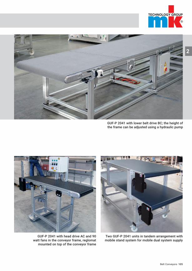
Two GUF-P 2041 units in tandem arrangement with mobile stand system for mobile dual system supply
GUF-P 2041 with lower belt drive BC; the height of the frame can be adjusted using a hydraulic pump
GUF-P 2041 with head drive AC and 90 watt fans in the conveyor frame, reglomat
mounted on top of the conveyor frame
Belt Conveyors

2
106
2
GUF-P 2041, head drive AC with support pan and transverse cleats
GUF-P 2041 upward offset AC head drive with belt slide bed on both sides
and front side wiper on the discharge
GUF-P 2041 with a special design as a vacuum conveyor for offset pressure plates
Belt Conveyors
Application Examples
2
110
2
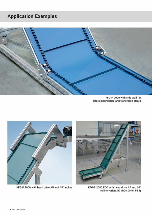
KFG-P 2000 with head drive AU and 45° incline KFG-P 2000 ECO with head drive AF and 60° incline variant B3 (B20.00.015-B3)
KFG-P 2000 with side wall forlateral boundaries and transverse cleats
Belt Conveyors
Application Examples
2
111
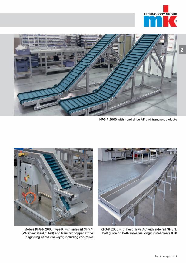
KFG-P 2000 with head drive AC with side rail SF 8.1, belt guide on both sides via longitudinal cleats K10
KFG-P 2000 with head drive AF and transverse cleats
Mobile KFG-P 2000, type K with side rail SF 9.1 (VA sheet steel, tilted) and transfer hopper at the
beginning of the conveyor, including controller
Belt Conveyors