bellsystem practices section c38.323 station operations...
TRANSCRIPT
BELLSYSTEM PRACTICES SECTION C38.323Station Operations Manual Issue 2, May, 1959Station Sets AT&TCo Standard
HAND TELEPHONE SETS--200 SERIES
IDENTIFICATION AND ASSEMBLY OF PARTS
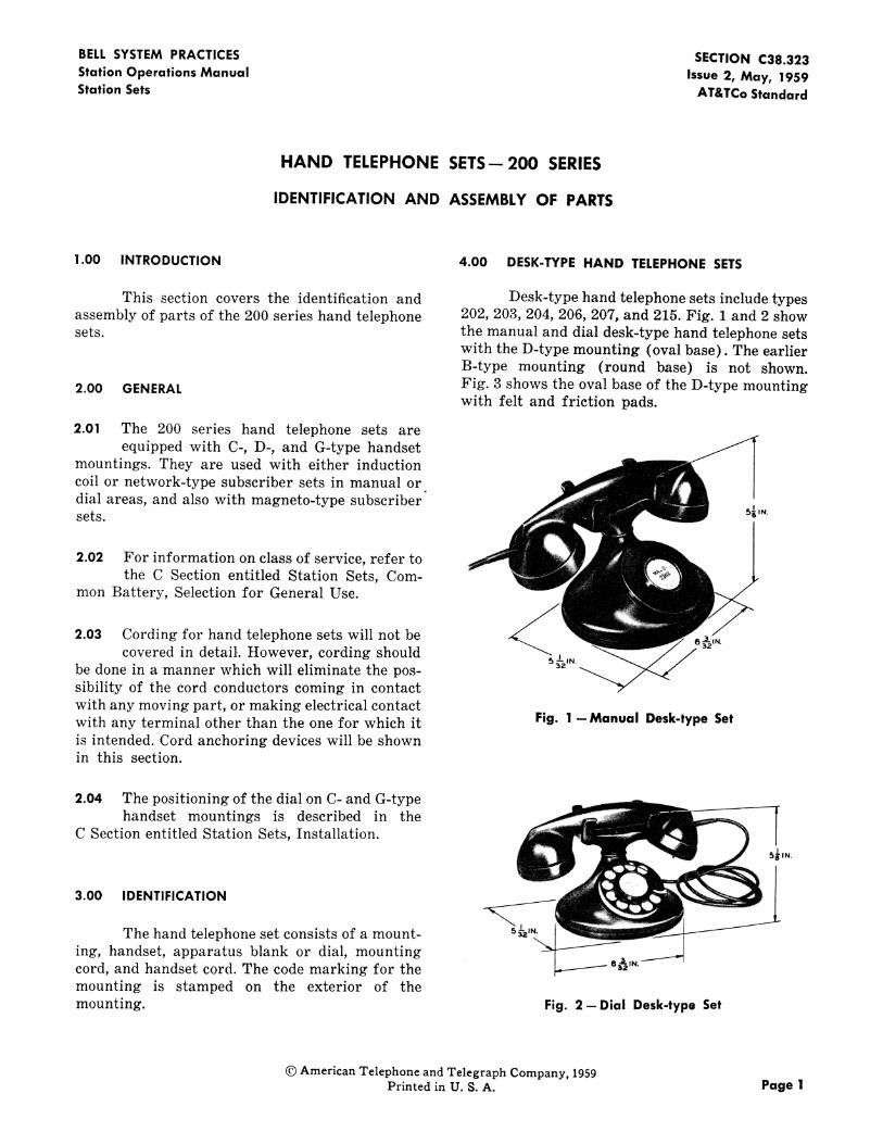
1.00 INTRODUCTION 4.00 DESK-TYPE HAND TELEPHONE SETS
This section covers the identification and Desk-type hand telephone sets include typesassembly of parts of the 200 series hand telephone 202, 203, 204, 206, 207, and 215. Fig. 1 and 2 showsets. the manual and dial desk-type hand telephone sets
with the D-type mounting (oval base). The earlierB-type mounting (round base) is not shown.
2.00 GENERAL Fig. 3 shows the oval base of the D-type mountingwith felt and friction pads.
2.01 The 200 series hand telephone sets areequipped with C-, D-, and G-type handset
mountings. They are used with either inductioncoil or network-type subscriber sets in manual or
dial areas, and also with magneto-type subscribersets. 5",_
2.02 For information on class of service, refer tothe C Section entitled Station Sets, Com-
mon Battery, Selection for General Use.
2.03 Cording for hand telephone sets will not be _,_
covered in detail. However, cording should 5_,,be done in a manner which will eliminate the pos-sibility of the cord conductors coming in contactwith any moving part, or making electrical contactwith any terminal other than the one for which it Fig. 1 --Manual Desk-type Setis intended. Cord anchoring devices will be shownin this section.
2.04 The positioning of the dial on C- and G-typehandset mountings is described in the
C Section entitled Station Sets, Installation.
55£SN.
3.00 IDENTIFICATION lThe hand telephone set consists of a mount- 5_,,
ing, handset, apparatus blank or dial, mountingcord, and handset cord. The code marking for the s_,_.mounting is stamped on the exterior of the
mounting. Fig. 2--Dial Desk-type Set
© American Telephone and Telegraph Company, 1959Printed in U. S.A. Page I

SECTIONC38.323
MOUNTING 5$CRE
-T4_IN.
9IN.
FRICTIONPADS
KS- 8035 -- FELTPAD
Fig. 3--Oval Base D-type Handset Mounting Fig. 4--Manual Hang-up C-type Set
5.00 HANG-UPTYPEHAND TELEPHONESETS _ s
,5.01 The hang-up hand telephone sets include
types 201,211, 212, 213, and 214 and utilize s_,,.the C- and G-type mountings.
12_. IN.5.02 The C-type mounting shown in Fig. 4 and 5
provides rotating adjustment to positionthe dial with respect to the user. The G-typemounting shown in Fig. 7 provides both rotatingand tilting adjustments for positioning the dial.
5.03 The C handset mounting is equipped with abracket for attaching the mounting, and it
will permit adjustment of the mounting to various Fig. 5 -Dial Hang-up C-type Setlengths of desk top overhang. The bracket for theG-type mounting serves.the same purpose and, inaddition, permits the handset to be hung fromeither the front or side. of the mounting.
6.00 ASSEMBLYOF PARTS
5.04 The 211J, 211L, and 212L hang-up handtelephone sets, equipped with the G-type
mounting and G-type handset, are furnished with D-type Handset Mounting
a chromium plated handset hook, but otherwiseare similar in external appearance to the handtelephone sets shown in Fig. 6 and 7. These hand 6.01 The D-type handset mounting is normallytelephone sets are designed to be used with the used with types 202, 203, 206, 207, and 215685- and 686-type subscriber sets. hand telephone sets (see Fig. 8 and 9).
Page:2

SECTION C38.323
50J APPARATUSBLANK
Fig. 6- Manual Hang-up G-type Set APPARATUSBLANKMOUNTING SCREW
Fig. 8-Assembly of D.type HandsetMounting (Manual)
i IN. 8_IN.
_ I iii PLUNGER BRACKET MOUNTING SCREW
_ P-215546 _LOCK WASHER
PLUNGER BRACKET
121N. PLUNGER SHAFTWASHER
i
gl
Fig. 7--Dial Hang-up G-type Set
6.02 When required, the 61N filter is used with o,,_,ou,_,,=s_,_wsthe D-type handset mounting. When mount-
ing a filter in a D-type handset mounting that is
equipped with a 6-type dial, the dust cover must be Fig. 9--Assembly of Filter on D-type Handsetremoved from the dial and left off. Mounting (Dial)
Care should be exercised that the plunger stem is
6.03 When replacing the plunger, the nickel- properly seated in the plunger bracket before thesilver guides should be on the right side plunger bracket mounting screw is tightened (see
viewed from the front of the handset mounting. Fig. 10).
Page 3
:TION C38.323
!
PLUNGER
P-239627
P-22562 I
HELICALSPRING
P-2163_,
EW DIAL
MOUNTINGSCREWS
ILl¢LU Fig. 11-Assembly of Dial on D-type
(_ Handset Mounting
e_i-x Fig. 10--Assembly of Plunger on D-typeLU Handset Mounting
E
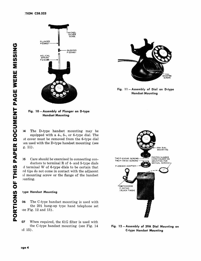
(,_ )4 The D-type handset mounting may be ;.:O equipped with a 4-_ 5-, or 6-type dial. TheI_ st cover must be removed from the 6-type dial i_,:i
IV _en used with the D-type handset mounting (see39A
Ill g. 11). : _'_ OlALMOUNTING
¢1.FASTEN NUMBER
:)5 Care should be exercised _n-connecting con- TwoP-231545_CREWS CARDHOLDERONTWO P-II8153 SCREWS
_ MOUNTING FOR
8_ ductors to terminal R of 4- and 5-type dials MANU_,sERv,_E7_d terminal W of 6-type dials to be certain that p-295_4o ADAPTER
" rd tips do not come in contact with the adjacental mounting screw or the flange of the handset ....
_" _3unting.u_
ZSWITCHHO0 KP-247921(BLACK FINISH)
type Handset MountingZ0 06 The C-type handset mounting is used with
_.. the 201 hang-up type hand telephone setIV _ee Fig. 12 and 13).
Oa_
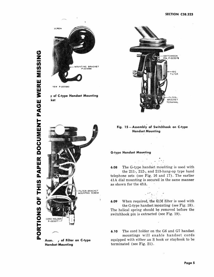
07 When required, the 61G filter is used with
the C-type handset mounting (see Fig. 14 Fig. 12--Assembly of 39A Dial Mounting onld 15). C-type Handset Mounting
age 4
SECTION C38.323
_CREW
Z PIN, P-223578
U}_I_ MOUNTING BRACKETP-223588
61G
FILTER
usREW P-223580
LU
y of C-type Handset Mounting rJLTER-
I.I.I :ket BRACI_ETTERMINAL
a_
l-Z Fig.15--Assembli of Switchhookon C-type
LLI Handset MountingE
OOI_ G-type Handset Mou_.ting
IV • . .
ILIJ
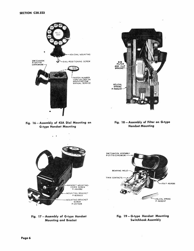
8_ 6.08 The G-type.handset moufiting is used with
the 211-, 212-, and 2t3-hang-up type hand8_ telephone sets (see Fig. 16 and 17). The earlier
41A dial mounting is secu/,ed in the same manner.. as shown for the 43A.
FILTER-BRACKET
MOUNTING SCREW ..-' ..•- .
u_ _ _ ; . ....O 6.09 When required, the 61Mfilter is used with
the G-type handset mbanting (see Fig. 18).
The helical spring should be removed before theZ switchhook pin is extracted (see Fig. 19).O CORD HOLDER
P-2_
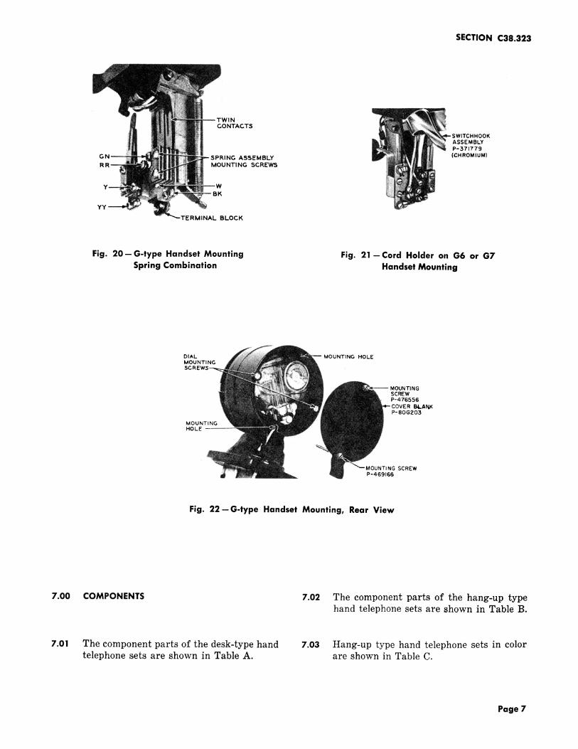
¢0 _ 6.10 The cord holder on the G6 and G7 handsetmountings will enable handset cords
8_ .Asse,. ; of Filter on C-type equipped with either an S hook or stayhook to beHandset Mounting terminated (see Fig. 21).
Page 5
SECTION C38.323
Q
DIAL MOUNTING
SWITCHHOOKP-3717 79 DIAL-POSITIONING SCREW 61M(CHROMIUM) FILTER
AND CLIPBRACKET
' FASTEN NUMBERCARD HOLDER ONMOUNTING FORMANUAL SERVICE
HELICALSPRING
P--465247
Fig. 16--Assembly of 43A Dial Mounting on Fig. 18--Assembly of Filter on G-typeG-type Handset Mounting Handset Mounting
SWlTCHH OOK ASSEMBLYP-371779 (CHROMIUM)
BEARING HOLE
T W IN CO NTACTS
NDSET MOUNTING- PIN P-464981COVER SCREW
P-464980
NTING BRACKETP-80G603 :,L,J_-
MOU NTI NG -BRAC I'kET ": LIC AL SPRING_'_ SCREW P- 465247
P-20702B
Fig. 17--Assembly of G-type Handset Fig. 19--G-type Handset MountingMounting and Bracket Switchhook Assembly
Page 6
SECTION C38.323
NCONTACTS
SWlTCHHOOKASSEMBLYP-371779
GN SPRING ASSEMBLY (CHROMIUM)R MOUNTING SCREWS
W
BH i
YY
TERMINAL BLOCK
Fig. 20--G-type Handset Mounting Fig. 21-Cord Holder on G6 or G7Spring Combination Handset Mounting
DIAL MOUNTING HOLEMOUNTING$CR
MOUNTINGSCREWP-476556COVER B4.AI_P-80G203
MOUNTINGHOLE
MOUNTING SCREWi P-469166
Fig. 22--G-type Handset Mounting, Rear View
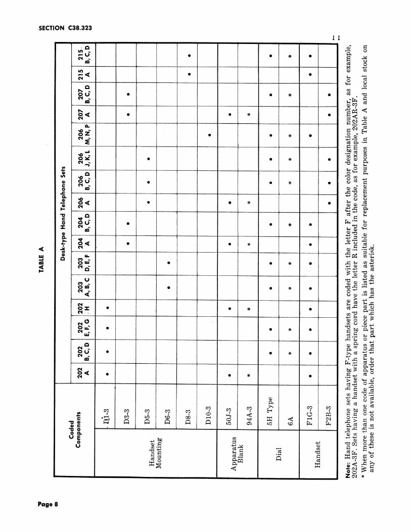
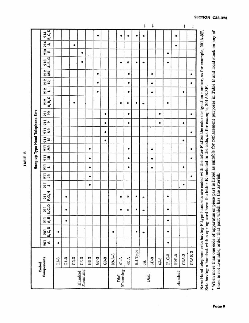
7.00 COMPONENTS 7.02 The component parts of the hang-up typehand telephone sets are shown in Table B.
7.01 The component parts of the desk-type hand 7.03 Hang-up type hand telephone sets in colortelephone sets are shown in Table A. are shown in Table C.
Page 7
SECTION C38.323
ud") ,. _ On,-U • • * •C'¢ ,,.
ON _
L@ _) m
a _OU • • ,.x- • _
o< • • _ • _
n_
_ "_ .._--J _
O_ • • * • O
.o- __q,,01
,o __o_ • . _ •o _ _
,_v • • * •
,c,c, ® u_ .,_,_ _'_..._, _ _ .__.,,_
° ,,,,,i
ore" • • "" • _ "mc,4_ _ • ._
,,,_ _
N.: . - _ - N "a__Lu" _. ,_,_ , _)
OU • • _ • _ _ _
o,< •C'q • ..x- • ._ _.._
! ! !
.o. _. _ _ _ _ _o ,_ _ < _ _ ,_._._°"00 L _'_::_ ,-_.,_""_
0 _, 4_a_mUE _ _ _ _0 _ _ _ "cl O0 0_I
U m',-'_ _ - _ . _-__ _:_ -,-.,
Page 8
SECTION C38.323
•i. .I. .I. .1.- , _. , . i i t__
i:3 ......... L ' _ ++-,a
. ............ _<"_" • • s:::P4 _ O
rip,,LLI • •
........ , ,U
c+,j .,.n,-,m • • -.X- • _ •
P...)<1; ,';,., o
-- 1""4
PIlE ........ _ ,-_I.m
-- ,., , .... _
u" I_, • • • •¢"4.. ,, ........... • i..--i
........ +m.,<_.,_,U
_':':P • + • , • .,,,+ • _<__ _ ..,, 0
o_ ..-,--_- • • • • '-_ _
_ ,.... .., ,
-z • • m,._ <_¢"4 _ _........ . .....
p,..,--,,+ _oo........... __ _
u_n 0,,..., _ _. . . . . _m. _• u,-,q
n.... _ ,-
:z: ""--' • ° • " _"=-- ....... e"-q
• • .,-, _,-._- ,............ _ _
_..., • " <_ ._ _m_ • ._ .+.+_............ _ i..,_.l_ ,_
n-,- (,,,_ • O. + • + •
.................. ._
_+ i _ ...............
,__..... ' ' " ;'4 • _,q _4
.......... _I
,..=+ + +o< . •
•"0o . . . c_ _ c_
o Q.. _ P,,-i-,i,._
o c_ _ _ _ _
_j_ -,,-4 _._ "
0-'_ "_'4 _ 0'2
U ,-_ _ .,.-,c_'_ .,._c_ ,-_ _ ._
o o
•' ' ' ' + " _ - 4["
Page 9

SECTION C38.323
TABLE C
r
Hang-up Type Hand Telephone SetsCodedComponents
211JR 211LR 211NR 211PRi i i
Ivory-50 • • • •, , .... ,
Green-51 • • • •
Gray-52
Red-53 • • • •
Brown-54 • •
Beige-55
Yellow-56 • • • •
Blue-57
White-58 • • o o
Rose Pink-59 • o o o
Light Beige-60 • o . .
Light Gray-61 • o o .
Aqua Blue-62 • o o o
L ill i i
Page 1010 Pages