belleview station - denver...urban design standards and guidelines these urban design standards and...
TRANSCRIPT

Belleview Station
Urban Design Standards and Guidelines April 18, 2007
Amended January 31, 2019
City & County of Denver
Front Range Land and Development Company

Belleview Station ________________________________________________________________________
Design Standards and Guidelines April 18, 2007
Amended January 31, 2019
City and County of Denver
Front Range Land and Development Company
Acknowledgements ________________________________________________
Front Range Land and Development Company Continuum Partners, LLC
Zimmer Gunsul Frasca Partnership
City and County of Denver
Department of Community Planning and Development Department of Public Works
Department of Parks and Recreation City Attorney’s Office
City Council
Peggy Lehmann, District 4
Prepared by: Civitas Inc.
Signature Page
RULES AND REGULATIONS
Rules and regulations adopted pursuant to Denver Revised Municipal Code, Section 12.18. Public hearing before the Denver Planning Board held on December 5, 2018.
BELLEVIEW STATION DESIGN STANDARDS AND GUIDELINES
Adopted April 18, 2007, Amended January 31, 2019
APPROVED FOR LEGALITY
City AttorneyCity and County of Denver
APPROVED AND ADOPTED
Executive Director, Community Planning and DevelopmentCity and County of Denver
Introduction 1
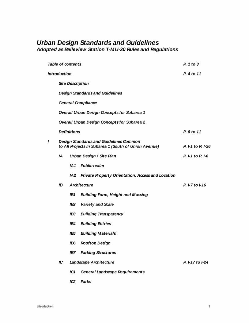
Urban Design Standards and GuidelinesAdopted as Belleview Station T-MU-30 Rules and Regulations
Table of contents P. 1 to 3
Introduction P. 4 to 11
Site Description
Design Standards and Guidelines
General Compliance
Overall Urban Design Concepts for Subarea 1
Overall Urban Design Concepts for Subarea 2
Definitions P. 8 to 11
I Design Standards and Guidelines Common to All Projects In Subarea 1 (South of Union Avenue) P. I-1 to P. I-26
IA Urban Design / Site Plan P. I-1 to P. I-6
IA1 Public realm
IA2 Private Property Orientation, Access and Location
IB Architecture P. I-7 to I-16
IB1 Building Form, Height and Massing
IB2 Variety and Scale
IB3 Building Transparency
IB4 Building Entries
IB5 Building Materials
IB6 Rooftop Design
IB7 Parking Structures
IC Landscape Architecture P. I-17 to I-24
IC1 General Landscape Requirements
IC2 Parks

Introduction 2
IC3 Plazas
IC4 Landscaping, Street Furniture and Lighting for Public Streets
IC5 Parking Lot Landscape Standards
IC6 Detention / Retention Drainage Area Standards
IC7 Screening, Fencing and Walls
IC8 Private Property Site Lighting/ Parking Lot Lighting
IC9 Plant Materials and Irrigation
ID Signs P. I-25 to I-26
II Design Standards and Guidelines Common to All Projects In Subarea 2 (North of Union Avenue) P. II-1 to II-25
IIA Urban Design / Site Plan P. II-1 to II-7
IIIA1 Public realm
IIIA2 Private Property Orientation, Access and Location
IIB Architecture P. II-8 to II-16
IIB1 Building Form, Height and Massing
IIB2 Variety and Scale
IIB3 Building Transparency
IIB4 Building Entries
IIB5 Building Materials
IIB6 Rooftop Design
IIB7 Parking Structures
IIC Landscape Architecture P. II-17 to II-23
IIC1 General Landscape Requirements
IIC2 Parks
IIC3 Plazas
IIC4 Landscaping, Street Furniture and Lighting for Public Streets

Introduction 3
IIC5 Landscaping, and Lighting for Private Streets, Alleys and Mews
IIC6 Parking Lot Landscape Standards
IIC7 Detention / Retention Drainage Area Standards
IIC8 Screening, Fencing and Walls
IIC9 Site Lighting/Permanent Parking Lot Lighting
IIC10 Plant Materials and Irrigation
IID Signs P. II-24 to II-25
III Design Review P. III-1 to III-5
IV Illustrations P. IV-1 to IV-12
Illustrations
Fig. A Site and Subareas
Fig. 1 Curb cuts
Fig. 2 Pedestrian Amenity Zones
Fig. 3 Pedestrian-Oriented, and Pedestrian-Supportive Use areas
Fig. 4 Upper Level Step-Back Areas
Fig. 5 Three Dimensional Application of Build-to and Upper Level Step-back Zones
Fig. 6 Non-Residential Ground Floor Transparency
Fig. 7 Non-Residential Upper Floor Transparency
Fig. 8 Important Corners
Fig. 9 Public and Possible Private Streets
Fig. 10 Mixed Use/Commercial Street Cross-Section
Fig. 11 Typical Mixed Use/Residential Street Cross-Section
Fig. 12 Concealment of Headlights of Cars in Parking Structures
Fig. 13 Techniques to Introduce Active uses into Parking Structures
Fig. 14 Pedestrian Path in a Large Parking Lot
Introduction 4
Introduction
Site Description
Site The 51 acre site is generally bounded by I 25, the Southeast Light Rail line, and Quebec St. on the east, Belleview Avenue on the south, Niagara St on the West, and a partial boundary of Union Avenue on the north, with a ‘pan-handle’ extending north of Union Avenue between Newport St., and I 25 approximately one-half mile. See Fig. A.
Most of the site has been rezoned TMU 30 with waivers and conditions, and has a General Development Plan (GDP) in place, adopted December 7, 2005. It is immediately adjacent to the Denver Tech Center to the east across I-25, west across Niagara Street and northwest across Union Avenue and Newport Way.
These Urban Design Standards and Guidelines were amended on January 31, 2019 to include the area shown on Figure A – Site and Subareas. This amendment does not modify the boundaries or applicability of the current Belleview Station General Development Plan.
Urban Design Standards and Guidelines These Urban Design Standards and Guidelines (enforced as Rules and Regulations) will guide developers and designers through the process of creating a transit-oriented and pedestrian-focused urban area, promoting a clear and consistent process for development within the Belleview Station Site. While the Standards and Guidelines give clear guidance, they are also reasonably flexible in order to respond to changing market conditions and building types, as well as to encourage design creativity. The Standards and Guidelines must strike a balance between flexibility and predictability so that they:
(1) Recognize that the Site will be built and evolve over time.
(2) Create and maintain a standard of quality that will sustain value.
(3) Promote a cohesive development pattern, while allowing for diversity and variety in the designand construction of individual projects.
(4) Assist city staff, planners, designers, developers, and users/owners in making consistent choicesthat reinforce the vision.
There are three components of the zoning based Standards and Guidelines – Intent statements, Standards, and Guidelines. Each of these has a specific purpose:
Intent The Intent statements establish the goals and objectives for each design topic. In circumstances where the appropriateness, applicability or absence of a Standard or Guideline is in question, the Intent statements are used to provide direction in resolving the question. However, the Intent statements are not Standards and Guidelines in themselves, and should not be directly used as Standards or Guidelines.
Standards Design Standards are objective criteria that provide specific direction based on an Intent statement(s). Standards use the term ‘shall’ to indicate that compliance is required.
Guidelines Design Guidelines provide further considerations and alternatives to accomplish the Intent statements. They often amplify a related Standard. When they amplify a Standard, they are desired but not mandatory criteria. Guidelines use the term ‘should’ or ‘may’ to denote that they are considered relevant in achieving the Intent Statement(s) and may be used by the applicant in
Introduction 5
seeking an alternative to a Standard that is not being met. In such a case, it must be demonstrated that the alternative meets one or more of the following criteria:
• The alternative equally or better achieves the Intent.
• The Intent will not be achieved by the application of the Standard in this particularcircumstance.
• The effect of other Standards and Guidelines will be improved by not applying this Standardin this particular circumstance.
• Unique site factors create a condition whereby the Guidelines would better achieve theIntent.
Within this document, where Intent Statements, Design Standards and/or Design Guidelines about public right of ways (ROW) are included, they are intended to convey and illustrate preferred approaches but are not formally adopted by the Department of Public Works. All matters impacting the ROW must be approved separately by the Department of Public Works.
General ComplianceAll projects in the Belleview Station must comply with all applicable statutes, ordinances, rules and regulations promulgated by the City and other agencies which have jurisdiction over the project, including revocable permits in the ROW, Americans with Disabilities Act, building permits, and permits for other public works matters.
Subareas The project area is divided into subareas so that differing development characteristics can be accommodated.
Subarea 1 (Located south of Union Avenue. See Fig. A):
Overall Urban Design Concepts
Transit-Oriented Development A light rail station has been constructed directly south of and below the Union Avenue bridge along a rail alignment adjacent to I-25. Bus interface with the light rail stop occurs on the Union Avenue bridge with elevators and stairs connecting the bus stops to the light rail station. An existing pedestrian underpass allows exclusive pedestrian and bicycle access from the north side of Union Avenue to the south side, not only linking the Union Avenue bus stops to the station, but also the Subarea 2 ‘panhandle’ to the urban core of Subarea 1. At-grade pedestrian crossings on Union Avenue provide direct access to bus stops for those not transferring to or from light rail.
Dense, Mixed Use and Walkable Urban Neighborhood The light rail station brings the opportunity to create a high density, mixed use, walkable urban neighborhood linked to a transit system that provides the opportunity to conveniently reach downtown, and ultimately a great deal of the metropolitan area including DIA and Boulder without a car. The site also has excellent freeway access. With both extraordinary transit and automobile access, the site can capture a wide range of the real estate market. The vision is to create a truly mixed use, high density neighborhood that combines residential, office, hotel, entertainment, dining, and retail together rather than just an office district, residential pod, or shopping center.

Introduction 6
Main Street (Newport Street) The spine of the neighborhood is a mixed use ‘main street’ environment along Newport Street. Ground floor pedestrian-active uses line the street, with residential, hotel and/or office space above the ground floor uses. The street is designed to support sidewalk cafes, and encourage night-time entertainment and dining activities. Garage access and curb cuts off of Newport are limited (but allowed) to minimize pedestrian / vehicular conflicts and to avoid widening the street to provide a continuous left turn lane. ‘Main Street’ (Newport Street) connects directly via Layton Street to the light rail station through a plaza, becoming the primary distributor of pedestrians throughout the development.
Street/Pedestrian Network and Variety A grid of streets and blocks distribute both vehicular and pedestrian circulation throughout the development. This avoids overloading of any particular street with excessive traffic. It also provides multiple choices for vehicular and pedestrian access, and good way-finding characteristics.
Building Form Lower rise building forms define street spaces with few gaps in the building continuity in Subarea I. Higher rise building forms (usually a continuation of the lower rise forms) are spaced to allow views of the mountains from a variety of locations throughout the site, and to provide sun and sky exposure to the street. Several sites lend themselves to the location of signature buildings that give focus and identity to the development.
Parks and Plazas Three primary open spaces are provided in Subarea 1: a plaza that is part of an open space/pedestrian system linking the light rail station to the corner of Newport Street and Layton Street; a linear open space along a street, and a quarter acre park embedded in a residential area. All of these spaces are counted as part of the required Aggregated Open Space requirement in the GDP.
Subarea 2: (Located north of Union Avenue. See Fig. A)
Overall Urban Design Concepts
Transit-Oriented Development The transit system serves Subarea 2 in several ways: 1) the light rail station is connected to Subarea II by a pedestrian underpass below Union Avenue that connects to a bike/pedestrian path extending the full length of Subarea 2 along its eastern edge; 2) sidewalks and bus stops on Union Avenue connect to Subarea 2 along both Newport Street north of Union Avenue and via elevators to the pedestrian/bicycle path along the district’s eastern edge. At-grade pedestrian crossings on Union Avenue provide direct access to bus stops for those not transferring to or from light rail.
Dense, Walkable Urban Neighborhood While the density and walkability remains high in Subarea 2, the urban character is much looser with more open space surrounding the buildings. Anticipated uses are primarily residential and office with limited opportunities for vertically mixed uses.
Street/Pedestrian Network Subarea 2 has but a single public street – Newport Way – which connects it directly to Subarea 1 across Union Avenue. Paralleling Newport Way is a linear Aggregated Open Space designed to accept a bikeway (multi-use trail). Buildings and their parking structures are served from this street, their drives crossing the Aggregated Open Space. As all Aggregated Open Spaces, the space must be accessible to the public and usable. It is not simply a landscaped front yard. A regular pattern of shade trees and a low wall or railing along the
Introduction 7
private property boundary (with frequent access points) provide an urban edge to the street. The bikeway (multi-use trail) will be connected to the underpass at Union Avenue.
Building Form Rather than create a continuous street edge, (now provided by the linear Aggregated Open Space) the buildings in this subarea stand alone as separate objects arrayed along the street. The buildings are also mid-rise to high-rise forms, designed to be seen from the expressway. They are set back from the street by the Aggregated Open Space, and they are separated from one another by open space (including a storm water detention basin), east / west pedestrian connections, and parking.
Parks and Plazas Perhaps the largest open space in this subarea is a storm water detention basin and its surrounding paths and landscaped areas. This basin will be designed as a well landscaped drainage element, and be edged by publicly usable Aggregated Open Space connected to the linear open space along Newport Way. However, the storm water detention basin itself is not useable open space and cannot be included in the Aggregated Open Space required in the development’s General Development Plan.
Introduction 8
Definitions
Aggregated Open Space: As allowed in the TMU30 zone district, the 20% unobstructed open space requirement for each zone lot may be replaced by10 percent of the total development land area if it is aggregated into a number of usable public open spaces, large enough to provide a clear amenity whether active or passive, accessible to the public, designed physically and visually to reinforce their public nature, and fulfill one or more of the following goals: enhanced pedestrian environment, enhanced connectivity, and enhanced or newly created public open space accessibility. The Aggregated Open Space requirement includes six types of spaces: 1) the open space surrounding the northern wet detention pond in Subarea 2, but not including the surface area of the wet pond itself; 2) a minimum 0.25 acre park that serves the residential population in Subarea 1; 3) a Transit Plaza at least 0.75 to 1.25 acres in size and flexible in its use; 4) publicly accessible, and usable linear open spaces in Subarea 1 adjacent to the public sidewalk and integrated with the adjacent streetscape; 5) a multi-use trail and linear open space along Newport Way in Subarea 2 designed as a pedestrian and bike connection from Subarea 2 to the light rail station via a tunnel under Union Avenue. 6) The Aggregated Open Space requirement will also include other additional open spaces which are large enough to provide clear amenities and are usable by and accessible to the public.
Amenity Zone: A portion of the public right-of-way between the curb and the Pedestrian Walking Zone reserved for streetscape elements that serve and enhance the pedestrian experience.
Applicant: The owner of the development parcel submitted to the Site Plan Review process.
Block Frontage: The portion of private property that abuts a public ROW, and extends from one public or private cross-street to another public or private cross-street, and as such, defines the length and width of a block.
Building Activity Zone: A portion of the Pedestrian Environment between the Pedestrian Walking Zone and the building face (see Figures 10 and 11). The Building Activity Zone may be wholly or partly within the public ROW. Primarily used where commercial uses are on the ground floor, this area is reserved for activities that relate to the pedestrian- active ground floor uses of a building, such as outdoor eating areas, window shopping, temporary display of goods, planter pots, etc. Where the ground floor uses are primarily residential, a building zone may include a landscaped front yard area, porches, stoops, steps or other transitional elements between the public street and a private residence. If such transitional elements are within the public ROW, then revocable permits and Department of Public Works approvals are required.
Build-To Zone: The horizontal zone formed at ground level by minimum and maximum building setbacks within which a portion of the building’s primary façade must be located. This zone may be limited in the vertical dimension so as to allow upper level building step-backs. The Build-To Zone locates the building along a street or public open space. It is different from the Building Activity Zone in that the Building Activity Zone demarcates a surface area within or adjacent to the pedestrian environment along a street or public open space where building related activities may occur such as an outdoor café, space for window shopping, and other activities.
General Development Plan (GDP): Refer to this project’s approved GDP (recorded on February 21, 2006, reception number 2006-030914) for further information regarding development criteria and street and open space locations.

Introduction 9
Hardscape: A term used to describe pedestrian environments that are primarily paved. Trees and other plantings are also components of hardscaped areas, but the primary surface of the ground plane is paving. Other durable, non-living materials such as metal grates, and compacted decomposed granite may be part of a hardscape palette.
Park: Primarily landscaped with trees, shrubs and turf or other ground cover, a park is all publicly usable space (including landscaping) and provides some or all of the following elements: passive open space for relaxation, some informal active recreation activities, play areas for children, and places to sit. For a space to be considered as a park, it must also directly adjoin a public street, be accessible to the public, and be at least 10,890 sq. ft. (1/4 acre) in area. A park is part of the Aggregated Open Space required in the GDP, but is not necessarily owned by the City.
Pedestrian Environment: The portion of the Public Right-of-Way reserved for the movement, activity, and enjoyment of the pedestrian. Generally, the Pedestrian Environment is made up of three zones: 1) an Amenity Zone or Tree Lawn, 2) a Pedestrian Walking Zone or Sidewalk, and 3) a Building Activity Zone. In many cases, the Building Activity Zone is wholly or partially on private property. (See Figures 10 and 11.)
Pedestrian Lighting: Lighting in the Public ROW intended to illuminate the pedestrian environment. Being distinct in purpose from street lights, which focus on enhanced traffic safety, pedestrian lighting is not included in the calculations for required roadway lighting. Pedestrian lighting provides additional illumination for real and perceived security, as well as detail, scale, ambience and emphasis within the pedestrian environment. Luminaire height and shielding are important to protect adjoining residential windows from glare and light trespass.
Pedestrian-Oriented Use: Building and land uses that actively accommodate, engage and respond to pedestrians and pedestrian activity and are consistent with the uses allowed by Ordinance #340, Series 2003. Typically, such a use is a street-front business that attracts the interest of pedestrians through the activities or goods within and allows views into commercial display windows and/or building interiors. Examples would include stores, galleries, restaurants, cafés, hotels, and cultural facilities like museums and libraries. Residential and office buildings may be included, provided they engage pedestrians with transparent façades opening on to lobbies and other active spaces.
Pedestrian-Supportive Use: Buildings and land uses that directly adjoin, help activate, and informally oversee pedestrian spaces such as sidewalks, plazas and parks and are consistent with the uses allowed by Ordinance #340, Series 2003. Such buildings and uses often have entries onto the pedestrian spaces, are on approximately the same level, and have windows overlooking the pedestrian space. Likely uses are residential, office, and institutional.
Pedestrian Walking Zone: That portion of a Pedestrian Environment reserved for the unobstructed movement of pedestrians, including persons with disabilities.
Plaza: Primarily hardscaped space as defined above, but including secondary landscaped areas, a plaza is expected to facilitate pedestrian connections, be edged by buildings and active uses, and to provide places to sit, have lunch, and meet people. A plaza must directly adjoin a Public ROW, be accessible to the public, and be at least 10,890 sq. ft. (1/4 acre) in area.
Introduction 10
Primary Building Façade: The building elevation or elevations that adjoin a Public ROW or public open space. It is expected that Primary Building Facades will include the main entrance to the building, or at least a secondary but clearly functioning entrance, and a number and amount of windows or glazing that meets, at minimum, the transparency standards of Section IB3 and IIB3 hereof. The Primary Building Façade is also expected to have the highest quality (or equal quality if all elevations herein are of high quality) of materials and detailing.
Project: The proposed development bounded by Belleview Avenue, Niagara Street, Olive Street, Quebec Street, Union Avenue, the proposed Newport Way, and the RTD Southeast Light Rail Line ROW, but excluding the out-parcel between the proposed Olive Street, the proposed Layton Avenue, the proposed Chenango Street, and the extension of Quebec Street. See Fig. A on Page IV-1.
Project Signs: Signs on public or private property that identify the overall project and its uses or events. Way-finding signs designed to guide pedestrians or motorists to shared destinations such as public parking garages, institutional or civic uses, and the transit station are also included in the Project Sign category. The provision in the GDP for the use of Section 59-430.13 (new code Section 59-315) for the creation of sign plans applying to all or any part of the project until a Comprehensive Sign Plan is approved remains in effect and is not superseded or modified by the standards and guidelines listed in Project Sign sections ID2 and IID2 hereof.
Public Right-of-Way (ROW): The area of land owned by the municipality (or other public entity) and dedicated as Right of Way which includes the street and/or a sidewalk. The Public Right of Way includes the roadway on which vehicles travel, and the Pedestrian Environment, typically composed of the Amenity Zone, the Pedestrian Walking Zone, and a Building Zone. The terms ‘Public Right-of Way’ or ‘street’ are not intended to include or refer to the I-25 expressway or the RTD Southeast Light Rail Line ROW.
Roadway: The portion of the Public Right-of Way reserved for vehicular movements and on-street parking usually measured from curb face to curb face.
Setback: The horizontal distance that separates a building from the front, side or rear property line. The design standards and guidelines establish setbacks more restrictive than Ordinance 340, Series 2003 and the GDP.
Site: A development parcel submitted to the Site Plan Review process.
Sidewalk (Attached): A paved Amenity Zone with trees in grates or landscaped areas in the paving which provide multiple hard surfaced paths between the curb and the sidewalk, and are landscaped with sod, ground cover, or other low plant material including mulches and crusher fines, and a paved Pedestrian Walking Zone, attached to the curb either by a continuous paved surface around tree grates or by multiple hard surfaced paths between landscaped areas.
Sidewalk (Detached): A paved Pedestrian Walking Zone separated from the curb by a tree lawn with street trees. The detached sidewalk may be a separate Pedestrian Walking Zone located between a tree lawn and a landscaped setback, or it may be attached to a paved Building Zone.

Introduction 11
Sight Triangle: A triangular area of the public sidewalk adjacent to a street intersection and describing a cone of vision experienced by the driver of a vehicle at that intersection. Planting and landscape improvements in the sight triangle are regulated by the Department of Public Works.
Street Edge: The cumulative effect of adjacent buildings and building elements such as walls, and permanent canopies that face onto and provide a perceptible boundary to the street. The street edge may be coincident with the ROW boundary or may be set back from it. It creates a generally consistent street wall that establishes a ‘sense of place’ on the street.
Street Façade: The portion of a building’s façade that faces and adjoins a public or private street.
Street Lighting: General illumination of the vehicular roadway typically provided from poles located within the public amenity zone. Street lighting must conform to the regulations established by the Department of Public Works. See also the definition of Pedestrian Lighting.
Streetscape: The combination and interaction of all of the elements that compose the Pedestrian Environment, including pedestrian street crossings.
Streetscape Elements: The physical components that make up the Pedestrian Environment, including but not limited to: paving, sidewalks, tree lawns, street trees, tree grates, landscape cut-outs in the paving, landscaping other than turf, street and pedestrian lighting, benches and other seating, planters, planter pots, trash receptacles, bike racks, newspaper corrals and condos, kiosks, bollards, bus shelters, shading devices, way-finding and identity signs, regulatory signs, and public art.
Tree Lawn: A portion of the Public ROW typically between the curb and the unobstructed pedestrian walk that is landscaped with trees and sod.
Upper Level Step-back: The horizontal distance that an upper portion of a building façade is set back from the face of the building’s lower portion.
Subarea 1 I -1
I Design Standards and Guidelines Common to All Projects in Subarea 1 (South of Union Avenue)
IA Urban Design/Site Plan IA1 Public realm
IA1.1 Vehicular Circulation and Access Note: While generally acceptable to Public Works and
Community Planning and Development, the following Intent Statements, Standards and Guidelines that refer to street design within a Public ROW, location of curb cuts, the design of curb cuts and driveways, or the design or location of other elements within the ROW do not limit Public Work’s, and Community Planning and Development’s ability to apply additional or different standards and guidelines, or to review and approve such elements on a case-by-case basis.
Intent i1 To establish a practical, interconnected system of streets
and walkways that allows easy orientation and convenient access.
i2 To design streets that respond to the differing needs of pedestrians, bicyclists and motorists.
i3 To utilize public spaces, such as streets, parks and plazas to organize and guide development.
i4 To encourage walking, bicycle and transit use as alternatives to driving alone.
i5 To reinforce a clear hierarchy and organization of circulation within the Belleview Station Development.
i6 To minimize conflicts between vehicles and pedestrians by limiting curb cuts along certain streets and building frontages.
i7 To connect to, and extend off-site pedestrian and bicycle paths into the development, and through to the light rail stop.
Standards s1 Curb cuts shall be limited on the streets or portions of
the streets as indicated in Fig. 1, P. IV-2. Mid-block vehicular access points shall be allowed except on Belleview Ave, and Union Ave. east of Newport St., where such access points are not allowed unless emergency vehicle access is needed.
s2 Driveways shall be perpendicular to the public ROW for at least 20 ft behind the back of the sidewalk.
s3 Curb cuts shall not be allowed within 50 linear feet of the face of curb of an intersecting street at a street corner.

Subarea 1 I -2
s4 Curb cuts shall not be allowed along Belleview Ave., and Union Ave. east of Newport St. with the possible exception of curb cuts for emergency vehicles.
Guidelines g1 Curb cuts and driveways should be shared or common
between multiple projects or lots. g2 A single curb cut should not be wider than the minimum
width required by the Department of Public Works for the safe movement of traffic.
g3 Drop-offs serving the entrances of specific uses such as
hotels may be allowed at the discretion of the Managers of Community Planning and Development, and Public Works.
g4 Streets should be designed as narrow as possible while
accommodating emergency vehicles, expected traffic and turning movements.
g5 As much as possible, streets should accommodate on-
street parking. g6 Curb radii should be as small as possible at street corners
in order to reduce pedestrian crossing distances. g7 Curb extensions or ‘bulb-outs’ at street intersections or
mid-block crossings may be provided where additional pedestrian emphasis and amenity is desired subject to approval by Public Works.
g8 Driveways and curb cuts may vary, with the approval of
Public Works, from the perpendicular given such circumstances as adjusting between a curving street and an orthogonally located building.
IA1.2 Pedestrian and Bicycle Circulation and Access
Intent i1 To establish an interconnected pedestrian and bicycle
network, both on-street and off-street, that provides clear orientation and convenient access to uses, parking and transit.
i2 To establish a hierarchy of pedestrian amenity and space
within street ROWs and adjoining private property. i3 To make effective connections to existing off-site
pedestrian and bicycle systems. i4 To provide separation between bicyclists, pedestrians
and vehicles.

Subarea 1 I -3
i5 To provide attractive pedestrian paths from destinations within block interiors, such as parking structures, to the public ROWs.
Standards s1 Detached sidewalks with tree lawns (which include
street trees) or attached sidewalks with amenity zones (which include street trees in grates or cut-outs) between the curb and walking zone shall be provided on all streets.
s2 Greater emphasis on pedestrian amenity and space shall
be provided on the streets indicated in Fig. 2, P. IV-3.
Guidelines g1 Pedestrian lighting should be provided on the streets
indicated in Fig. 2, P. IV-3. Maintenance of these pedestrian lights will be provided by a Metropolitan District or other form of a private maintenance district.
g2 With the approval of the Department of Parks and
Recreation, variations from regularly spaced or otherwise consistent streetscape elements (including street trees) may be provided where special conditions occur, where greater emphasis may be desired, where space is limited, or where correspondence with adjoining plaza or park design is appropriate.
IA1.3 Parks
(See Landscape Architecture Section IC2 for Detailed Standards and Guidelines)
IA1.4 Plazas
(See Landscape Architecture Section IC2 for Detailed Standards and Guidelines)
IA1.5 Streetscape (See Landscape Architecture Sections IA1.2 and IC4 for Standards and Guidelines)
IA2 Private Property Orientation, Access and Location
IA2.1 Building and Use Orientation Intent i1 To orient front façades and main entries toward streets
and plazas.
i2 To provide informal observation of publicly-accessible streets and open spaces from adjoining buildings.
i3 To promote the incorporation of pedestrian-oriented
uses at the ground level street frontage of a building. i4 To provide continuity of pedestrian-oriented use and
building form that will support an active public environment.
Subarea 1 I -4
i5 To define or visually contain the three dimensional space of the street or public open space.
i6 To promote sun and sky exposure to public streets and
plazas, allowing for shade and shelter as appropriate. i7 To spatially or formally emphasize key corners. i8 To provide a transition between the public space of the
street, and the private space of the building interior. i9 To locate buildings close to the street. i10 To insure that high quality design and materials are
provided for all sides of a building that adjoin, or are directly visible from a street or public space.
Standards s1 A minimum of 75% of the length of ground floor street
facades of buildings located in Pedestrian-Oriented Use Areas shall provide space for pedestrian-oriented uses, including building and garage pedestrian entries and lobbies within the 75% calculation. (See Fig. 3, P. IV-4.)
s2 In Pedestrian-Oriented Use Areas, 75% of any building’s
street-facing facade up to a minimum of forty five feet (45’) in height shall be located within a build-to-zone formed by the minimum setback of three feet (3’), and the maximum setback of ten feet (10’) from the street R.O.W. or public park or plaza boundary. Building facades at or lower than 45 ft in height must follow this standard. Portions of building facades higher than 45 ft in height that are required to step back (see IB1.s2), or choose to step back, are excepted from this build-to zone standard. (See Fig. 3, P. IV-4.)
s3 In Pedestrian-Oriented Use Areas, at least 80% of the
total block frontage shall be occupied by buildings with front facades to which standards IA2.1.s1, and IA2.1.s2 apply at full build-out.
s4 In areas designated as Pedestrian-Supportive Use Areas,
65% of any building’s street-facing facade up to a minimum forty five feet (45’) in height shall be located within a build-to zone formed by the minimum setback of three feet (3’), and the maximum setback of fifteen feet (15’) from the street R.O.W. or public plaza boundary. Buildings at or lower than 45 ft in height must follow this standard. Portions of building facades higher than 45 ft in height that are required to step back (see IB1.s2), or choose to step back, are excepted from this build-to zone standard. No minimum length of block frontage is required to be occupied by a building. (See Fig. 3, P. IV-4.)

Subarea 1 I -5
s5 Buildings shall orient Primary Façades and functioning entries toward the street, toward a public plaza, or pedestrian way that directly leads to a street.
s6 Encroachments within the 3 foot minimum front setback
imposed by the Belleview Station Rules and Regulations (see IA2.1.s2 and s4) as well as the Build-To Zone shall be allowed as per Sec. 59-312(4) .
Upper level encroachments within the 3 foot minimum setback and the Build-To Zone must be high enough above the ground level finished grade to allow the continuation of the Pedestrian Environment to extend to the minimum setback line. The minimum height above finished grade for awnings, projecting signs or other minor ancillary elements attached to the front façade shall be eight (8) feet. Substantial and permanent building elements projecting from the primary façade such as balconies, and enclosed bays may also encroach into the 3 foot front setback and the Build-To Zone, so long as they are either intermittent or clustered, and comprise only a minority of the area of the front façade. The minimum height above grade for such substantial and permanent elements is twelve (12) feet. Encroachments below the ground level finished grade, such as underground parking, vaults, basements, and foundations shall also be allowed within the 3 foot minimum setback and the Build-To Zone as per Sec. 59-312(4).
At ground level finished grade, steps, stairs, and ramps as well as outdoor seating and railings may encroach within the 3 foot minimum setback and the Build-To zone as per Sec. 59-312(4).
Guidelines g1 Within the Build-to Zone, the majority of the building
façade should be oriented parallel or up to 15° of parallel to the street on which it fronts. Building forms above the vertical extent of the Build-To Zone may orient perpendicular to the street, or at an angle to the street.
g2 Buildings and landscape features should be oriented to
frame views of special buildings and open spaces. g3 Building frontages should be located close to the street. g4 Building frontages should be aligned with each other,
although some minor differences can provide variety and relief. Building alignments may also vary in relation to a curving street.
g5 Buildings may be set back further than the maximum
setback at important corners in order to provide
Subarea 1 I -6
additional pedestrian space, or to provide exposure to signature buildings and building elements. (See Fig. 9)
g6 Buildings may be set back further than the maximum
setback to create usable public open space such as plazas, or park-like green spaces.
IA2.2 Alley, Service Area, and Trash Area Location
Intent i1 To minimize the visual presence of off-street service
functions, such as deliveries and refuse pick up, by locating service access away from primary public access points and providing screening.
Standards s1 Service and delivery facilities and utility appurtenances
such as meters, transformers, and switch gear shall be separated from the primary public building entries and shall be screened, or designed to be inconspicuous, from view from the public ROW, public parks and plazas by means such as:
• Locating underground. • Locating internally within buildings or special
enclosures. • Locating to the rear or side of a building. • Providing walls, fences, and/or landscaping of
sufficient height and density to screen the facility from public view.
• Locating along alleys internal to the blocks or, in
Subarea II, adjacent to the expressway. Guidelines g1 Refuse storage and pick-up areas should be combined
with other service and loading areas.. g2 Mechanical, electrical, and other utility appurtenances as
well as equipment should be located within the interior of the property or block.
g3 In certain circumstances, street loading from designated
on-street loading zones may be allowed.
IA2.3 Parking Location Intent i1 To minimize the visual presence of automobile
circulation, surface parking and garages by locating parking access away from primary building entries and providing screening where necessary.
Subarea 1 I -7
Standards s1 Surface parking shall not be permitted between the
front facades of residential, institutional, and commercial buildings and the public right-of-way.
s2 Within the designated Pedestrian-Oriented Use Areas,
(see Fig. 3, P. IV-4), parking garages shall be located to the interior of the block or over ground floor pedestrian-oriented uses, and except for access drives, shall not interrupt the ground-floor street frontage.
Guidelines No Guidelines

Subarea 1 I -8
IB Architecture
IB1 Building Form, Height and Massing Intent i1 To shape the location of building walls, and to define and contain
the street space in a way that reinforces pedestrian activity and creates a coherent “place”.
i2 To moderate scale changes between adjacent buildings, including
buildings across the street from each other. i3 To provide human scale along public and private streets and
sidewalks. i4 To promote sun and sky exposure to public streets, parks and
plazas, allowing for shade and shelter as appropriate. i5 To emphasize important corners, and create views of important
buildings along streets.
Standards s1 Taller buildings shall establish scale relationships with immediately
adjoining lower neighboring buildings through the application of at least one of the following methods:
• Align architectural features and/or fenestration, particularly
within the lower floors of the buildings.
• The graduation of the building height and mass through steps in the building form.
• The provision of other intermediate forms (such as corner
elements, protruded or recessed bays, or expressed structural elements), to transition between higher and lower buildings.
• The use of smaller scaled materials, fenestration or other
building elements on the lower floors of the buildings. s2 For all buildings higher than ninety feet (90’) and within the
designated step-back frontages (see Figs. 4, P. IV-5 and 5, P. IV-6), a minimum ten foot (10’) upper level step-back shall be provided for at least fifty percent (50%) of the street facing building façade for any portion of the building higher than forty five feet (45’). This step-back shall occur from the building face within the build-to zone between forty five feet (45’) and ninety feet (90’) above the average finished grade at the property line. Step-backs below 45 ft. in height and 50% or more of the facade are not allowed.
Guidelines g1 Upper level stepbacks may be waived if other approaches or
techniques are provided to insure scale compatibility and sky exposure.

Subarea 1 I -9
IB2 Variety and Scale Intent i1 To create buildings that provide human scale in the lower portions
of street facing facades.
i2 To create buildings that provide visual interest and variety.
Standards s1 Building facades below 90 feet in height (or below an upper level
step-back in the street façade) that face public ROWs or public spaces shall be designed to provide human scale, interest and variety. Examples that meet this standard include but are not limited to the following techniques:
• Variation in the building form such as recessed or projectingbays or balconies, contrasting shapes, or changes in basicmodules.
• Expression of architectural or structural modules.
• Diversity of window size, shape or patterns.
• Provision of permanent exterior shading devices, and/or otherprojecting elements designed to cast shadows.
• Solar energy collectors integrated into the façade.
• Entries and windows recessed at least 3 inches
• Window, storefront or curtain wall framing at least 1 inchbeyond the plane of the glass.
• Clearly expressed glass, or panel attachments.
• Emphasis of building entries or important corners throughprojecting or recessed forms, detail, color or materials.
• Variations of material, material modules, joints and connectiondetails, surface relief, color and texture.
• Tighter, more frequent rhythm of architectural / structural /window modules, subdividing the building façade into smaller,more human scaled elements.
A minimum of three of these techniques, or techniques similar to those listed shall be applied to the street or public space facing façade.
s2 When a building is higher than ninety feet (90’), that portion of the building above 90 feet in height shall exhibit variation and interest on all facades, whether facing a public ROW or public space or not, (but not necessarily smaller scale), through techniques that include but are not limited to the following:

Subarea 1 I -10
• Variation in the building form such as recessed or projectingbays, including protruding or recessed balconies, contrastingshapes, or changes in basic modules.
• Expression of architectural or structural modules.
• Diversity of window or curtain wall size, shape or patterns.
• Variations of material, material modules, joints and connectiondetails, surface relief, color and texture.
• Provision of permanent exterior shading devices, and/or otherprojecting elements designed to cast shadows.
• Special forms, detailing or materials to create a unique andfinished building top or profile against the sky.
• Special architectural emphasis at important corners.
A minimum of two of these techniques or techniques similar to those listed shall be applied to facades higher than ninety feet (90’).
s3 For buildings higher than ninety feet (90’), windows shall be provided on all facades except such narrow facades that may be returns of protruding bays, expressions of vertical elevator / stair or mechanical cores, structurally required shear walls, or that are inset recesses designed to break up the mass of the building.
s4 All facades or forms of a building that adjoin a public ROW, park, or public space, or are clearly seen from such streets or spaces, shall receive a high level of design attention and detailing, using high quality materials.
Guidelines g1 Large areas of undifferentiated or blank building facades should be
avoided.
g2 Portions of the street-facing façade that are stepped back from the façade closest to the street ROW should be allowed greater simplicity in façade detailing and scale.
IB3 Building Transparency (Wall to Window Ratios and Glass Characteristics) IB3.1 Non-Residential Uses
Intent i1 To provide transparent glazing at the ground floor that
insures the visibility of active uses or goods.
i2 To provide transparent upper level glazing sufficient to be aware of internal space and activities, lighting, or products when viewed from the street or public spaces.
i3 To ensure a proportion of window openings to wall opacity that allows informal observation of activities to
Subarea 1 I -11
and from public streets and spaces, creating a building that feels open and welcoming.
Standards s1 In Pedestrian-Oriented and Supportive Use Areas, (see
Fig. 3, P. IV-4), at least 50% of the ground floor non residential (excluding parking levels or structures) street-facing façade (measured from finished grade at the ground floor to finished second floor) shall be composed of transparent glazing designed to allow pedestrians to view activities inside the building, or shop windows related to these activities. This shall not preclude the use of fritting, or shade devices eight feet or more above the sidewalk level to control solar heat gain.
s2 In Pedestrian-Oriented Use Areas, (see Fig. 3, P. IV-4) at
least 35% of a street-facing non-residential (excluding parking levels or structures and hotels) façade above the ground floor shall be composed of transparent glazing.
s3 In Pedestrian-Supportive Use areas, (see Fig. 3, P. IV-4) at
least 30% of a street-facing non-residential (excluding parking levels or structures and hotels) façade above the ground floor shall be composed of transparent glazing.
s4 To insure a high level of transparency at the ground level
of street-facing facades , the coefficient of transparency for glass (the Visible Light Transmittance or VLT) shall be at least 0.65.
s5 Where transparent glass is used above the ground floor
of street-facing facades, the VLT shall not be less than 0.60.
s6 To insure an appropriate level of outside visible light
reflectivity above the ground floor level of street facing facades, the coefficient of reflectivity (the visible Light Reflectance or VLR) shall be not more than 0.25 for any transparent glass, and no reflective coatings shall be permitted on the first surface of the glass.
s7 To insure an acceptably low level of outside visible light
reflectivity at the ground floor of street-facing facades, the coefficient of reflectivity or VLR for glass used on the ground floor shall not be more than 0.20.
Guidelines g1 A variety of glass types may be used at or above the
ground floor, such as translucent glass, etched glass, glass block, channel glass, and multilayered glass walls with variable louvers as long as the minimum transparency standards are met..
g2 Opaque glass, or spandrel glass may be used on or
above the ground floor but may not be counted as

Subarea 1 I -12
meeting the required minimum percentage for transparent or translucent glass as required in IB3.1.s1 which limits such requirements to the Pedestrian Oriented Use Areas.
g3 Low-E coatings are encouraged on the second and third
surfaces in order to provide greater energy conservation while maintaining a high degree of transparency.
g4 Sun screens and shades are encouraged as long as they
do not significantly obstruct views through the window from the outside into the inside.
g5 Above the ground floor (for building facades within the
Pedestrian Oriented Use Area), where window proportions, more solid, masonry walls or smaller glass exposures on south or west facades are appropriate, a lower window to wall ratio may be allowed so long as all of the glazing meets the upper level transparency standard IB3.1.s4.
g6 Fritting (the bonding of an opaque coating on the inside
surface of the glass) or shade devices eight feet or more above the sidewalk level may be provided to control solar heat gain.
g7 Where higher performing glass may be the only feasible
way to provide the energy conservation necessary to achieve a U.S. Green Building Council LEED certification, the reflectivity coefficients listed in IB3.1.s6 may be modified so long as the overall reflectivity of the façade has been considered and any clearly identified glare problems have been mitigated.
g8 Where grade changes or functional requirements may
result in higher than normal ground floor heights, the 50% transparency standard listed in I3.1.s1 may be modified so long as the intent to provide a largely transparent ground floor is maintained.
g9 A lower ratio of transparency to opacity may be allowed
on the upper floors of a building if additional architectural treatment is provided.
IB3.2 Residential Uses
Intent i1 To provide a level of transparency at upper floors
sufficient to be aware of internal activities when viewed from the street or public spaces.
i2 To ensure a high enough proportion of window
openings to wall opacity so that informal observation of activities on public streets and spaces is possible, and that a building feels open and welcoming.

Subarea 1 I -13
Standards s1 In Pedestrian – Oriented and Pedestrian-Supportive Use
Areas, (see Fig. 3), at least 25% of ground floor (measured from finished ground floor to finished second floor) and upper floor residential façades and at least 25% of upper floor hotel facades (excluding parking levels) that face a public street or public open space shall be composed of transparent glazing (meeting standard IB3.1.s5).
Guidelines g1 A lower percentage of window to wall may be
appropriate to preserve privacy and to mitigate noise and glare, so long as all of the glazing meets the upper level transparency standard IB3.1.s5.
g2 Low-E coatings are encouraged on the second and third
surfaces in order to provide greater energy conservation while maintaining a high degree of transparency.
g3 Fritting (the bonding of an opaque coating on the inside
surface of the glass) or shade devices eight feet or more above the sidewalk level may be provided to control solar heat gain.
IB4 Building Entries
Intent i1 To enhance the scale, activity, and function of the public streets. i2 To promote the convenience of pedestrian activity and circulation
along the street by creating external, street-oriented entries. i3 To visually emphasize the major entry or entries to a building or
ground floor use.
Standards s1 All buildings shall provide at least one primary building entry
oriented to or visible from a public right-of-way (ROW). s2 All street-oriented building entries shall be directly connected to
the public sidewalk by a paved walk, stair or ramp. s3 Major building entries shall be emphasized through such design
devices as changes in plane, differentiation in material and/or color, differentiation in canopy or awning design, greater level of detail, enhanced lighting, ornament, art, and building graphics.
s4 Within the Pedestrian Oriented Use Area (see Fig.3, P. IV-4),
ground floor tenant entries shall be provided along and oriented to the public ROW, or be visible from the public ROW.
Guidelines g1 Primary entries that are located on the side of a building may be
allowed so long as they are visible from the public ROW, are

Subarea 1 I -14
directly connected to the public sidewalk by a paved walk, stair or ramp, and comply with IB4.s3.
IB5 Building Materials
Intent i1 To use lasting materials that weather well, resist vandalism, and
need little maintenance. i2 To use materials that incorporate human scale in their modules and
texture. i3 To use materials which convey a sense of quality, permanence and
attention to detail. i4 To use materials that support a more sustainable environment.
Standards s1 Façades that face the street or Aggregated Public Open Space shall
be clad in durable, high quality materials, including but not limited to the following:
• Brick, stone, clay block, terra cotta. • Architectural pre-cast concrete, cast stone, architecturally
finished cast-in-place concrete, cement stucco. • Architecturally treated, integrally colored concrete masonry
units. • Glass and other glass products. (See IB3.s5 for reflectivity) • Non-glare metal panels, metal shingles, metal cladding
systems. • Durable synthetic materials such as glass reinforced concrete,
cement boards, or other similar materials. s2 All facades above sixty (60’) feet in height or exposed to
permanent view from adjoining streets or buildings, whether they face the street / public space or not, shall be clad in durable and high quality materials as described in standard IB5s1.
s3 Vinyl siding shall not be used as an exterior wall cladding.
Guidelines g1 Exterior Insulating Finish System (EIFS) should not be used on
ground floors that face the street or public space or above the fourth floor of any building, except for rooftop mechanical equipment enclosures or screening.
g2 Wood paneling of a durable species or treated to insure long-term
durability may be used as a wall material on the lower facades of a building as an infill material. However, this guideline is not intended to encourage the use of wood siding.

Subarea 1 I -15
g3 Synthetic materials that imitate natural materials should be avoided. Synthetic materials should be used in ways that reflect their intrinsic character.
g4 Building materials should include new technologies and materials
that promote environmental sustainability and energy resource responsibility.
g5 Highly polished metal materials that may cause glare should be
avoided.
IB6 Rooftop Design Intent i1 To reduce the visual clutter of rooftop equipment as seen from the
street. i2 To reduce equipment noise impacts onto adjacent residential uses. i3 To incorporate rooftop elements into the architectural design of
the building. Standards s1 All roof mounted mechanical and electrical equipment,
communication antennae or dishes shall be enclosed within a penthouse, or screened from public view from the street.
Guidelines g1 Rooftop design should be designed either to be unobtrusive and
subordinate to the building’s form and façade architecture, or should be designed to complete the building’s architectural expression.
g2 EIFS may be used as a material for roof top screening or enclosures.
IB7 Parking garages Intent i1 To mitigate the visual and noise impacts from parking garages onto
public streets and open spaces, such as noise from vehicles and mechanical equipment, glare of vehicle headlights, and the light trespass of internal lighting.
i2 To design the garage facades adjoining public streets and open
spaces so that they are compatible in character and quality with adjacent buildings.
i3 To provide ground floor pedestrian-active uses within parking
garage facades that adjoin a public street or open space. i4 To avoid large areas of undifferentiated or blank walls along public
streets or open spaces. i5 To line the face of a parking structure that would otherwise adjoin
a street or public space with residential, commercial or institutional uses to screen the parking from the public ROW.

Subarea 1 I -16
i6 To place parking structures underground, or internal to the development, block or building.
Standards s1 Garage openings within facades that adjoin a public street or open
space shall be vertical and horizontal, not sloped. s2 Spandrel panels or walls shall be at least 3 foot 6 inches high in
order to conceal the headlights of parked cars from pedestrians on the opposite side of the street. (See Fig. 12, P. IV-12.)
s3 For any parking structure façade directly adjoining, or within 20 ft.
of the Newport Street and Layton Ave. ROWs in Subarea 1, pedestrian-active uses shall be provided on its ground floor along at least 75% of its street frontage including lobbies, and pedestrian access areas.
s4 Rooftop parking deck lighting shall be limited to 20 feet in height,
and shall be low cut-off type fixtures. s5 Parking garage facades oriented to public streets and Aggregated
Open Spaces shall include architectural elements that provide variety and human scale, such as:
• expression of building structure; • differing patterns or sizes of openings; • changes in plane of walls or cladding systems (at least 3
inches); • changes in material, pattern or color; • expression of material or cladding system modules; • joint patterns and attachment details; • signs, art or ornament integral with the building; • quality, durable materials with smaller scaled modules,
patterns, or textures; • the concealment of the parking garage interior at the street or
Aggregated Open Space-facing ground floor level;
At least three (3) of these or similar techniques shall be applied.
Guidelines g1 Ground floors of parking garages that adjoin a public street or
Aggregated Open Space other than on Newport St, or Layton St. should incorporate pedestrian-active or pedestrian supportive uses for some of the total length of the street or Aggregated Open Space oriented ground floor facades. This length may include lobbies for parking garage pedestrian access as well as lobbies for

Subarea 1 I -17
other uses. Parking levels, in any case, may be located above the ground floor pedestrian active or supportive uses.
g2 Encourage parking garage facades adjoining public streets or
Aggregated Open Spaces to be partially or wholly concealed behind a building structure that can accommodate other active uses such as commercial, institutional or residential.
g3 Architectural and/or pedestrian active use standards for a parking
garage may be waived if planned future building phases conceal the parking garage or add further building elements that provide pedestrian active uses or architectural interest to it.
g4 Landscaping integrated into the design of the parking garage may
provide a substitute for one of the techniques listed in IB7.s5. g5 Where garages face streets other than Newport St or Layton St., or
Aggregated Open Spaces and where it is impractical to include any ground floor uses or to conceal the garage behind other street-facing uses, the architectural treatment of the entire garage façade, especially the ground floor, should meet standard IB7.s5.
g6 The ground floor portion of a parking garage façade adjoining a
public street or public open space other than Newport Street and Layton Ave. should be designed to accommodate active ground floor uses such as commercial, institutional, live-work, residential, art or craft studios, or other active uses if or when such uses are economically feasible. Techniques for the accommodation of such uses may include but not be limited to the following:
• horizontal ground and second floor levels; • mechanical, plumbing and electrical chases and/or conduit for
ground floor uses planned or included in the design of the parking garage;
• direct, and level ground floor access to the adjoining public
sidewalk; • ground floor infill panels that can accommodate or be easily
removed to accommodate future commercial storefront enclosure systems;
• ground floor height sufficient to reasonably accommodate
other future uses. For example, 12 feet of height from the finished ground floor to the underside of the second floor slab or structure would allow for most commercial and residential uses.
g7 In cases where a parking garage may precede future phases that
may conceal or add further architectural elements or uses to it, landscaping or landscape elements should be provided along the parking garage facades that are clearly visible to a street or public open space until such future phases or elements are built.

Subarea 1 I -18
IC Landscape Architecture (See also Section IA1 Public Realm) IC1 General Landscape Requirements
Intent i1 To ensure that all areas of the site receive landscape/hardscape
treatment.
i2 To encourage landscape/hardscape design that is resource efficient, improves site permeability, reduces the urban heat island effect and is easily maintained.
Standards s1 All areas of the site at full build-out not covered by buildings,
structures, parking areas, service areas, walks and bikeways, or other imperviously surfaced functional areas shall be landscaped or hardscaped.
s2 All landscaping shall be irrigated. (See Section IC9)
Guidelines g1 General landscape design, including the location of landscaped
areas, their type, form and materials, should endeavor to control erosion and limit sedimentation of municipal water drainage systems.
g2 Permeable paving should be provided wherever feasible.
g3 Native, dry land vegetation may be irrigated only to establish its initial health.
IC2 Parks Intent i1 To provide spaces that are open to the public, and are of adequate
size, configuration, and proportion to serve a variety of active and passive needs, including informal recreation, relaxation and community interaction.
i2 To introduce substantial amounts of vegetation into the urban environment.
i3 To provide organizing space for groups of buildings.
i4 To provide areas of shade, sun, and wind protection.
Note: The following standards and guidelines apply only to that space labeled as a required ‘park’ in the Belleview Station GDP, or that fits the definition for park and is 10,890 sq. ft. ( ¼ acre) or larger.
Standards s1 All parks shall be easily viewed and accessible from a public
R.O.W., and have at least 15% of its perimeter abutting a public ROW.
s2 Where grade changes or other obstructions need to be accommodated in a public park, no such grade changes or
Subarea 1 I -19
obstructions may be higher or lower than three feet (3’) above or below the sidewalk within twenty feet (20’) of the public R.O.W. Wherever possible, walls and retaining walls defining or containing such grade changes shall be at seating height. Ramp or stair handrails and guardrails along raised public areas are excluded from this standard.
s3 A minimum of one lineal foot (1LF) of seating for every two hundred fifty square feet (250 SF) of park area shall be provided for seating in all parks. Seating may include benches, movable chairs and seat walls no higher than 30 inches and no less than 12 inches wide. Seating thirty inches (30”) wide or more may count double providing there is access to both sides.
s4 At least 60% of a park’s surface shall be covered by live landscaping, including mulch and other surface treatments designed to support the growth of landscaping. At least 30% of the park’s surface shall be turf grass or a low growing and stable ground cover capable of supporting foot traffic. Ground cover shall be ADA accessible as required.
s5 Each park shall provide at least one tree for every 4800 sq. ft. of park area. Fractions over 50% of a 4800 sq. ft increment shall be rounded up to include an additional tree.
s6 All publicly accessible parks shall be useable.
Guidelines g1 Landscaping and/or turf that can accommodate pedestrian use
should be considered as the primary surface treatment, with paving/hardscape as secondary surface treatments.
g2 Deciduous shade trees should be provided near seating areas.
g3 Trash receptacles should not be placed immediately adjacent to benches or limited seating areas.
g4 Pedestrian lighting should be extended through parks to form part of a continuous system for those on foot.
g5 Park standards may be modified for special park conditions, configurations, functions, or size.
IC3 Plazas Intent i1 To provide spaces that are open to the public which serve as areas
for relaxation and community interaction, and create variety and interest in the public realm.
i2 To introduce elements of nature into the urban environment.
i3 To allow for additional space adjacent to buildings and public right-of-ways to accommodate special amenities such as café seating, sculpture and planters.

Subarea 1 I -20
i4 To provide organizing space for groups of buildings.
i5 To design spaces that can accommodate high levels of pedestrian use.
Note: The following standards and guidelines apply only to the space labeled as a required ‘plaza’ in the Belleview Station GDP, or that fits the definition for plaza and is 10,890 sq. ft. (1/4 acre) or larger.
Standards s1 Each plaza shall provide at least one tree for every 4800 sq. ft. of
plaza area. Fractions over 50% of a 4800 sq. ft increment shall be rounded up to include an additional tree.
s2 A minimum of 15% of the area of a plaza shall be composed of planting materials (grass, ground covers, planting beds, etc.).
Guidelines g1 Paving/hardscape should be considered as the primary surface
treatment, with landscaping and/or turf that can accommodate pedestrian use as secondary surface treatments.
g2 Deciduous shade trees should be provided near seating areas.
g3 Trash receptacles should not be placed immediately adjacent to benches or limited seating areas.
g4 Other amenities, such as water features, public art, power outlets, and drinking fountains, should be incorporated into a plaza.
g5 Plaza standards may be modified for special plaza conditions, configurations, functions, or size.
IC4 Landscaping, Hardscaping, Street Furniture and Lighting for Public Streets (See also Section IA1.2 Pedestrian and Bicycle Circulation and Access)
IC4.1 Landscaping Intent i1 To select street trees that provide shade in the summer,
and allow sun to reach pedestrian and vehicular surfaces in the winter.
i2 To select street trees that do well in urban conditions.
i3 To select trees and other plant materials that are drought tolerant, and suitable to the climate and/or native to the region.
i4 To provide healthy growing conditions for all plant materials within an urban street environment.
i5 To coordinate the design and landscaping of the private property’s front setback with the design and landscaping of the sidewalk area in the public street ROW and/or with any park or plaza open to the public.

Subarea 1 I -21
Standards s1 All trees in the public ROW shall be selected and planted
to meet the requirements of the City Forester. s2 Coniferous trees shall not be allowed in the public
R.O.W. s3 Where trees are located in hard surfaced amenity zones,
well drained and aerated tree pits or trenches shall be provided, the minimum exposed surface area of which (provided by cut-outs or grates) shall be twenty five (25) square feet (5 ft. by 5 ft.).
s4 The design and materials of the sidewalk / amenity zone
in the public ROW shall be extended into the Build-to Zones formed by either the 3 foot minimum front setback line and the 10 foot maximum setback line, or the 3 foot minimum front setback line and the 15 foot maximum setback line except where a use, particularly residential, may be better served by landscaping in the Build-To zone
Guidelines g1 Where special conditions occur, variations to the above
standards may be allowed, with approval of the City Forester, so long as the health and growth of the plant materials are not compromised.
g2 The minimum exposed surface area for trees in hard
surfaced amenity zones may be reduced with approval of the City Forester, where other techniques are used to insure the health and growth of the tree, or where it can be shown that a lesser area is adequate.
g3 The extension of the design and materials of the public
ROW’s streetscape into a building’s Build-to Zone may be modified to incorporate a front yard, a landscaped strip adjacent to the building or other transitional forms from the public space of the street or park to the private space of the building’s interior.
IC5 Parking Lot Landscape Standards
Intent i1 To screen the view of surface parking lots and the cars on them
from adjoining streets, open spaces and pedestrian ways. i2 To reduce the urban heat-island effect (heat gain and re-radiation
of heat) of larger areas of paving exposed to sunlight. i3 To reduce the size and scale of parking lots. i4 To block the glare from car headlights and parking lot lighting onto
adjoining streets and private property.

Subarea 1 I -22
Standards s1 A minimum 5 foot wide planting strip with a dense, continuous
hedge (minimum 3 feet high, maximum four feet high within three years of installation) or a metal railing (minimum 3 feet high, maximum 4 feet high) or a low wall (minimum 3 feet high, maximum 4 feet high) without a planting strip shall be provided along all parking lot perimeters that adjoin public streets, parks or plazas open to the public. Breaks in the hedge / railing or wall shall be provided at minimum 100 foot increments to allow pedestrian passage from the lot to the street or public space. This Standard supersedes all Street Frontage Landscaped Planting Strip standards in the Rules and Regulations for the Landscaping of Parking Areas.
s2 For contained urban parking lots (bounded at final build-out on at
least three sides by generally continuous building edges, and not, at final build-out, have frontage on the ROW) of 50 spaces or less, a minimum of 3% of the interior surface parking area of the parking stalls exclusive of vehicular circulation shall be landscaped.
s3 For parking lots greater than 300 spaces, at least one pedestrian
path internal to the parking lot, separated from parked cars and driving lanes with vertical curbs, and at least 5 ft. in width clear of car bumpers shall be provided. This pedestrian path shall be directed toward a primary building entry. A pedestrian crossing of a driving lane from such a path shall be marked with striping or special paving.
Guidelines g1 Parking lot perimeter treatments should be designed to screen the
view of parked cars from the street or adjoining parks and plazas open to the public, and to reduce the impact of headlights onto adjoining development.
g2 Landscaped areas in large surface parking lots (200 spaces or more)
should visually minimize the perception of large, continuous expanses of pavement.
g3 For small urban lots as described in IC5.s2, required interior
landscaping may be substituted for additional perimeter landscaping, railings or walls.
g4 Berms should not be used as a method of parking lot screening
along streets. IC6 Detention/Retention Drainage Area Standards
Intent i1 To accommodate on-site storm water detention areas in ways that
integrate them into an overall landscaped open space system. i2 To landscape on-site storm water detention areas in ways that
allow multiple uses such as passive recreation, or wildlife habitat. i3 To landscape on-site storm water detention areas so that they are
visually attractive in all seasons.
Subarea 1 I -23
i4 To use plant materials, bio-treatment swales, and wetland plant communities to provide water quality treatment, and allow passive recreation and/or wild life habitat.
Standards s1 Plant materials and land form techniques shall be used to provide
water quality treatment. Live plant materials shall cover the entire detention area with the exception of man-made elements. Site detention areas shall minimize the use of pea gravel, rip-rap, rock, cobble stones or other non-organic landscape materials.
s2 All man made elements such as retaining walls, head walls and
inlet structures shall be designed to integrate with the natural landscaping of the detention area. Integration shall be achieved by such techniques as minimizing or stepping the height of retaining or head walls, using natural stone as facing materials for the wall or structure finish, coloring and/or texturing concrete surfaces, or using smaller scaled precast or concrete block retaining wall systems.
s3 Water quality treatment shall comply with the City and County of
Denver’s Water Quality Management Plan, 2004.
Guidelines g1 In addition to separate detention areas, site detention may also be
located in or on parking areas, building roofs, and underground locations with consideration given to the special design elements required for detention in these areas.
g2 Opportunities for walking, bicycling and sitting in a more natural
habitat should be provided.
IC7 Screening, Fencing and Walls Intent i1 To screen or buffer service areas, refuse containers and
mechanical/utility equipment from views from streets, open spaces and adjacent properties.
i2 To provide security for private and common spaces not open to the
general public. Standards s1 All fences and gates viewable from the street shall incorporate
building materials and detailing that is architecturally compatible with the building to which they are related.
s2 Screening enclosures for refuse containers and service areas shall
be incorporated into building architecture and utilize the same or similar materials as the principle building. Screen walls and fences shall be one foot higher than the object being screened, but not more than eight feet high on all sides where access is not needed. An opaque metal gate shall be included where required for complete screening.

Subarea 1 I -24
Guidelines g1 Where topography or building forms create special conditions,
screen wall height, and/or location requirements may be modified. g2 Where building form or architecture suggests that ancillary
structures or walls contrast with the primary building, fences and screen walls may differ in design and materials from the primary building.
IC8 Private Property Site Lighting/Parking Lot Lighting
Intent i1 To provide a safe and secure environment for parking lot, drop-off
areas, and private or open spaces accessible to the public. i2 To provide a safe and secure environment for all exterior walkways. i3 To distinguish the parking lot lighting system from the street
lighting systems in order to clarify the ‘street’ from the parking lot and its circulation system.
i4 To create night-time interest through the lighting of landscape
elements. i5 To provide lighting design consistency within each development i6 To establish high quality in lighting design and lighting fixtures. i7 To limit light trespass and glare onto adjacent properties and onto
the adjoining streets and open spaces. i8 To limit night sky light pollution.
Standards s1 Parking lot lighting shall be provided by low cut-off luminaires
designed to incorporate elements to reduce glare, such as translucent, obscure or refracting lenses; low wattage light sources or shielding devices.
s2 Parking lot light poles shall be a maximum of 25 feet in height. Guidelines g1 Paths from parking lots and parking garages to building entries
should be provided with pedestrian lighting.
IC9 Plant Materials and Irrigation Intent i1 To ensure that specified plant materials are healthy, meet industry
standards, and are suited to an urban environment. i2 To encourage water conservation practices. Standards s1 Required landscaping (including landscaping in the public R.O.W.)
and landscaping on private property shall meet the following minimum size requirements:

Subarea 1 I -25
• Deciduous trees: 2½ inch caliper. • Ornamental trees: 1½ inch caliper. • Coniferous trees: five (5) feet tall. • Shrubs: five (5) gallon • Vines and perennials: one (1) gallon • Mass ground covers: 2¼ inch with a minimum planting
spacing of 6 inches to 9 inches
See also Section IC4 Street Design. s2 All non-residential and multi-family residential properties shall be
irrigated with automatic irrigation or sprinkler systems. s3 Water shall be applied to the landscape in a manner that will result
in the overall conservation of water for irrigation. Guidelines g1 Plant materials should be predominantly drought tolerant species
suitable to the climate and/or native to the region. Where substantial pedestrian use is expected such as at tree lawns, and portions of parks designed to encourage informal recreational activities, irrigated turf, either native or non-native, may be used, so long as the overall plant pallette is primarily drought tolerant.
Subarea 1 I -26
ID Signs
Note: Sign requirements are addressed in the Denver Zoning Ordinance for all zone districts, including mixed use districts (Sec. 59-315). The mixed use district sign regulations govern within Belleview Station TOD’s GDP area unless specifically modified below. ID1 Building Signs
Intent i1 To provide a clear identification of businesses and buildings. i2 To create signs and graphic elements that are appropriate to and
expressive of the use or product that they identify. i3 To respect the architectural character and design of the building in
the determination of the number, type, size, location and design of signs.
i4 To create high quality, professionally fabricated signs using durable
materials. i5 To foster creativity, and uniqueness in sign design appropriate to a
contemporary urban setting. i6 To prevent visual clutter.
Standards s1 Mixed-use buildings shall provide locations on the commercial
areas of the building façade that are specifically designed to accommodate changeable tenant signage including wall signs, projecting signs and window signs. Structure, materials, detailing and power sources shall be designed with consideration of signage installation requirements and shall be readily adaptable and reparable as tenant sign needs change.
s2 Orientation of any illuminated sign or light source shall be directed
or shielded to reduce light trespass and glare onto nearby residential uses.
s3 Signs shall be constructed of high quality, durable materials. All
materials must be finished to withstand corrosion. Guidelines g1 Signs should creatively use two- and three-dimensional form,
profile, and iconographic representation (e.g. lighting, typography, color, and materials) in expressing the character of the use, the identity of the development, the character of the neighborhood, and the architecture of the building.
g2 Signs should fit within the architectural features of the façade and
complement the building’s architecture. g3 Signs should not overlap and conceal architectural elements. g4 Locations for illuminated signage should be oriented to the public
right-of-way.

Subarea 1 I -27
g5 Internally illuminated cabinet signs with light colored or white translucent plastic faces are discouraged.
ID2 Project signs
Intent i1 To create an organized, integrated and creative system of signs,
sign structures, sign lighting and graphics that identify the project, its uses and special events within the project.
i2 To provide a system of interrelated way-finding signs. i3 To minimize overall visual clutter of multiple project signs. i4 To avoid conflicting with City regulatory signs. Standards s1 All project signs shall conform to the Denver Zoning Code, any
required comprehensive sign plans, and all requirements for signs and graphics in the public R.O.W.
s2 Signs shall be constructed of high quality, durable materials. s3 No portion of a project sign shall be located closer than 25 feet
horizontally from any other project sign. Guidelines g1 Project signage should be located in the public amenity zone of the
street aligned with, or otherwise integrated into the design of the street trees, pedestrian and street lighting, and street furniture.
g2 Project signage may also be located at important entry locations to
the development. g3 Way-finding signage and kiosks may be located along streets, at
intersections or in public parks and plazas.
End of Subarea 1 Standards and Guidelines
Subarea 2 II-1
II Design Standards and Guidelines Common to All Projects in Subarea 2 (North of Union Avenue)
IIA Urban Design/Site Plan IIA1 Public realm
IIA1.1 Vehicular Circulation and Access Note: While generally acceptable to Public Works and
Community Planning and Development, the following Intent Statements, Standards and Guidelines that refer to street design within a Public ROW, location of curb cuts, the design of curb cuts and driveways, or the design or location of other elements within the ROW do not limit Public Work’s and Community Planning and Development’s, ability to apply additional or different standards and guidelines, or to review and approve such elements on a case-by-case basis.
Intent i1 To establish a practical, interconnected system of streets
and walkways that allows easy orientation and convenient access.
i2 To design streets that respond to the differing needs of pedestrians, bicyclists and motorists.
i3 To utilize public spaces, such as streets, parks and plazas to organize and guide development.
i4 To encourage walking, bicycle and transit use as alternatives to driving alone.
i5 To reinforce a clear hierarchy and organization of circulation within the Belleview Station Development.
i6 To minimize conflicts between vehicles and pedestrians by limiting curb cuts along certain streets and building frontages.
i7 To connect to, and extend off-site pedestrian and bicycle paths into the development, and through to the light rail stop.
i8 To share driveway access to parking structures, parking lots, and/or drop-off areas.
Standards s1 Curb cuts shall be limited on the streets or portions of
the streets as indicated in Fig. 1, P. IV-2. Mid-block vehicular access points shall be allowed except on Union Ave. east of Newport St., where such access points are not allowed unless emergency vehicle access is needed.
s2 Driveways shall be perpendicular to the public ROW for at least 20 ft behind the back of the sidewalk.

Subarea 2 II-2
s3 Curb cuts shall not be allowed within 50 linear feet of the face of curb of an intersecting street at a street corner.
s4 Curb cuts shall not be allowed on Union Ave. east of Newport St. with the possible exception of curb cuts for emergency vehicles.
Guidelines g1 Curb cuts and driveways should be shared or common
between multiple projects or lots.
g2 A single curb cut should not be wider than the minimum width required by the Department of Public Works for the safe movement of traffic.
g3 Drop-offs serving the entrances of specific uses such as hotels may be allowed at the discretion of the Managers of Community Planning and Development, and Public Works.
g4 Streets should be designed as narrow as possible while accommodating emergency vehicles, expected traffic and turning movements.
g5 As much as possible, streets should accommodate on-street parking.
g6 Curb radii should be as small as possible at street corners in order to reduce pedestrian crossing distances.
g7 Curb extensions or ‘bulb-outs’ at street intersections or mid-block crossings may be provided where additional pedestrian emphasis and amenity is desired subject to approval by Public Works.
g8 Driveways and curb cuts may vary, with the approval of Public Works, from the perpendicular given such circumstances as adjusting between a curving street and an orthogonally located building.
IIA1.2 Pedestrian and Bicycle Circulation and Access Intent i1 To establish an interconnected pedestrian and bicycle
network, both on-street and off-street, that provides clear orientation and convenient access to uses, parking and transit.
i2 To establish a hierarchy of pedestrian amenity and space within street ROWs and adjoining private property.
i3 To provide separation or visual / textural definition between bicyclists, pedestrians and vehicles.

Subarea 2 II-3
i4 To provide attractive pedestrian paths from building entries, to the public pedestrian / bicycle path along Newport Way.
i5 To provide an attractive and comfortable pedestrian connection along Union Ave. from the bus transfer area on Union Avenue to the Newport Street / Newport Way intersection.
Standards s1 Detached sidewalks with tree lawns (which include
street trees) between the curb and walking zone shall be provided on Newport way.
s2 Greater emphasis on pedestrian amenity and space shall be provided on the streets indicated in Fig. 2, P. IV-3.
s3 At least one path, a minimum of ten feet wide and suitable for bicyclists and pedestrians, shall be provided from the bicycle / pedestrian path(s) along Newport Way to the pedestrian / bicycle underpass at Union Avenue (See Fig. 2, P. IV-3.)
s4 The sidewalk / streetscape zone along Newport Way shall be at least 15 feet wide from the ROW to the face of the curb, comprising an amenity zone at least eight feet wide from the face of the curb that includes street trees, and a minimum 6 feet wide walking zone.
s5 A continuous linear Aggregated Open Space, a minimum width of 40 feet shall adjoin the east side of the Newport Way ROW, and extend from the northern end of the development’s frontage along the ROW to or within approximately 150 feet of the Newport Way / Union Avenue intersection.
s6 A path or paths suitable for bicyclists shall be provided within the adjoining Aggregated Open Space. Such a path shall be connected to the existing Newport Way sidewalk at the north end of the project.
s7 The linear Aggregated Open Space shall have an urban character created by a regular tree canopy, a generally level ground plane suitable for a variety of informal uses, turf or other pervious surfaces that can accommodate foot traffic as well as ground covers and landscaping, seating and other outdoor furniture, lighting, paved paths connecting building entries to the public ROW, and other outdoor amenities that support residential, office or other commercial uses.
s8 A low wall or ornamental railing between three feet and four feet in height shall define the eastern and northern edge of the Aggregated Open Space along Newport Way. The wall may be freestanding. However, the wall

Subarea 2 II-4
must be consistent in material, design and height as measured from the ROW boundary throughout its length. Finished grade may be sloped up against it so long as at least 12 inches of the wall is exposed to view from the Aggregated Open Space.
s9 Vehicular drop-offs or parking are not allowed within the Aggregated Open Space along Newport Way.
s10 Driveways shall be allowed to cross the Aggregated Open Space area to provide access to parking garages and lots, and service areas. However, these driveways, within the Aggregated Open Space, must be coordinated with the finished grade of the Aggregated Open Space so that the drives do not interrupt the continuity of the Aggregated Open Space’s ground plane.
Guidelines g1 Pedestrian lighting should be provided on the streets
and/or within the Aggregated Open Space indicated in Fig. 2, P. Iv-3. Maintenance of these pedestrian lights will be provided by a Metropolitan District or other form of a private maintenance district.
g2 With the approval of the Department of Parks and Recreation, variations from regularly spaced or otherwise consistent streetscape elements (including street trees) within the ROW may be provided where special conditions occur, where greater emphasis may be desired, where space is limited, or where correspondence with adjoining plaza or park design is appropriate.
g3 A transition zone between the private uses and buildings adjoining the Aggregated Open Space and the Aggregated Open Space itself should be provided to allow for private outdoor use, and, if desired, privacy for ground floor uses.
g4 The walking / bicycling zone in the ROW may be reduced or eliminated if an additional continuous pedestrian and/or bike path is provided within a adjoining Aggregated Open Space.
IIA1.3 Parks (See Landscape Architecture Section IIC2 for any additional standards and guidelines.)
IIA1.4 Plazas (See Landscape Architecture Section IIC2 for any additional standards and guidelines.)
Subarea 2 II-5
IIA1.5 Streetscape (See Landscape Architecture Sections IIA1.2 and IIC4 for standards and guidelines.)
IIA2 Private Property Orientation, Access and Location IIA2.1 Building and Use Orientation
Intent i1 To orient front façades and main entries toward streets
open spaces or views.
i2 To provide informal observation of publicly-accessible streets and open spaces from adjoining buildings.
i3 To promote the incorporation of pedestrian-supportive
uses at the ground level street frontage of a building. i4 To promote sun and sky exposure to public streets and
plazas, allowing for shade and shelter as appropriate. i5 To spatially or formally emphasize key corners. i6 To provide a transition between the public space of the
street, and the private space of the building interior. I7 To insure that high quality design and materials are
provided for all sides of a building that adjoin, or are directly visible from a street or public space.
Standards s1 Within Pedestrian Supportive Use Areas, 25% of any
building’s street facing facade up to at least 35 five feet (35’) in height shall be located in a build-to zone formed by the minimum setback of three feet (3’) and a maximum setback of ten feet (10’) from the street ROW or Aggregated Open Space boundary.
s2 At least 50% of the length of ground floor facades of
buildings located in the Pedestrian Supportive use areas shall provide space for Pedestrian Supportive uses. Building and garage pedestrian entries and lobbies are included within the Pedestrian Supportive use definition.
s3 A building’s front door shall be on a façade that adjoins
a street or an Aggregated Open Space that is attached to a street, or be visible from the street.
S4 Encroachments within the 3 foot minimum front setback
imposed by the Belleview Station Rules and Regulations (see IA2.1.s2 and s4) as well as the Build-To Zone shall be allowed as per Sec. 59-312(4).
Upper level encroachments within the 3 foot minimum setback and the Build-To Zone must be high enough above the ground level finished grade to allow the continuation of the Pedestrian Environment to extend to
Subarea 2 II-6
the minimum setback line. The minimum height above finished grade for awnings, projecting signs or other minor ancillary elements attached to the front façade shall be eight (8) feet. Substantial and permanent building elements projecting from the primary façade such as balconies, and enclosed bays may also encroach into the 3 foot front setback and the Build-To Zone, so long as they are either intermittent or clustered, and comprise only a minority of the area of the front façade. The minimum height above grade for such substantial and permanent elements is twelve (12) feet. Encroachments below the ground level finished grade, such as underground parking, vaults, basements, and foundations shall also be allowed within the 3 foot minimum setback and the Build-To Zone as per Sec. 59-312(4).
At ground level finished grade, steps, stairs, and ramps as well as outdoor seating and railings may encroach within the 3 foot minimum setback and the Build-To zone as per Sec. 59-312(4).
Guidelines g1 Buildings and/or landscape features should be oriented
to frame views of special buildings and open spaces. g2 Given that a low wall edging the Aggregate Open Space
described in IIA.1.2s9 and the Aggregate Open Space’s urban character described in IIA1.2s8 provide spatial definition and structure to the street, building orientation and form along Newport Way may vary from a parallel or perpendicular street orientation so long as the standard IIA2.1s1 is followed.
g3 Pedestrian active ground floor uses are encouraged
within building frontages along the north side of Union Avenue, and along Newport Way.
g4 Buildings may orient Primary Façades and functioning
entries toward the street, toward a public open space, or pedestrian way that directly leads to a street. Buildings may also orient Primary Facades toward mountain views.
IIA2.2 Alley, Service Area, and Trash Area Location.
Intent i1 To minimize the visual presence of off-street service
functions, such as deliveries and refuse pick up, by locating service access away from primary public access points and providing screening.
Standards s1 Service and delivery facilities and utility appurtenances
such as meters, transformers, and switch gear shall be separated from the primary public building entries and

Subarea 2 II-7
shall be screened, or designed to be inconspicuous, from view from the public ROW, parks and plazas by means such as:
• Locating underground. • Locating internally within buildings or special
enclosures. • Locating to the rear or side of a building. • Providing walls, fences, and/or landscaping of
sufficient height and density to screen the facility from public view.
• Locating along alleys internal to the blocks or, in
Subarea 2, adjacent to the expressway.
Guidelines g1 Refuse storage and pick-up areas should be combined
with other service and loading areas.. g2 Mechanical, electrical, and other utility appurtenances as
well as equipment should be located within the interior of the property or block.
g3 In certain circumstances, street loading from designated
on-street loading zones may be allowed.
IIA2.3 Parking Location Intent i1 To minimize the visual presence of automobile
circulation, surface parking and garages by locating parking access away from primary building entries and providing screening where necessary.
Standards s1 Surface parking shall not be permitted between the
front facades of residential, institutional, and commercial buildings and the public right-of-way.
Guidelines No Guidelines
Subarea 2 II-8
IIB Architecture
IIB1 Building Form, Height and Massing Intent i1 To articulate each building as a separate object by its form, height,
location and massing, rather than joining or aligning the buildings to form a street edge.
i2 To moderate scale changes between adjacent buildings, including
buildings across the street from each other. i3 To provide human scale along public and private streets and
sidewalks, and off-street public bikeways and walkways i4 To promote sun and sky exposure to public streets, parks and
plazas, allowing for shade and shelter as appropriate. i5 To emphasize important corners, and create views of important
buildings along streets. Standards s1 Taller buildings shall establish scale relationships with immediately
adjoining lower neighboring buildings within the project through the application of at least one of the following methods:
• Align architectural features and/or fenestration, particularly
within the lower floors of the buildings.
• The graduation of the building height and mass through steps in the building form.
• The provision of other intermediate forms (such as corner
elements, protruded or recessed bays, or expressed structural elements), to transition between higher and lower buildings.
• The use of smaller scaled materials, fenestration or other
building elements on the lower floors of the buildings. Guidelines No Guidelines
IIB2 Variety and Scale Intent i1 To create buildings that provide human scale in the lower portions
of street facing facades. i2 To create buildings that provide visual interest and variety. Standards s1 All building facades below 90 feet in height and in a façade within
the front build-to zone (excluding attached or detached parking garages – see IIB7) shall be designed to provide human scale, interest and variety.

Subarea 2 II-9
• Variation in the building form such as recessed or projecting bays, including protruding or recessed balconies integrated into the architecture, contrasting shapes, or changes in basic modules.
• Provision of an upper level step-back in the building form of a
street-oriented façade at or above a height from finished grade of at least 35 feet.
• Expression of architectural or structural modules. • Diversity of window size, shape or patterns. • Entries and windows recessed at least 3 inches. • Emphasis of building entries through projecting or recessed
forms, detail, color or materials. • Variations of material, material modules, joints and connection
details, surface relief, color, transparency and texture. • Provision of permanent exterior shading devices, and other
projecting elements designed to cast shadows. • Solar energy collectors integrated into the façade. • Tighter, more frequent rhythm of architectural / structural /
window modules, subdividing the building façade into smaller, more human scaled elements.
A minimum of four of these techniques shall be applied to the street or public space facing façade.
s2 When a building is higher than ninety feet (90’), that portion of the
building above 90 feet in height shall exhibit variation and interest on all facades, through techniques that include the following:
• Variation in the building form such as recessed or projecting
bays, including protruding or recessed balconies, contrasting shapes, or changes in basic modules.
• Expression of architectural or structural modules. • Diversity of window or curtain wall size, shape or patterns. • Variations of material, material modules, joints and connection
details, surface relief, color and texture. • Provision of permanent exterior shading devices, and/or other
projecting elements designed to cast shadows. • Special forms, detailing or materials to create a unique and
finished building top or profile against the sky.

Subarea 2 II-10
• Special architectural emphasis at important corners. A minimum of two of these techniques shall be applied to facades higher than ninety feet (90’).
s3 Windows shall be provided on all facades (excluding attached or
detached parking garages – see IIB7) except such narrow facades that may be returns of protruding bays, expressions of vertical elevator / stair or mechanical cores, structurally required shear walls, or that are inset recesses designed to break up the mass of the building.
s4 All facades shall receive a high level of design attention and
detailing, using quality materials. Guidelines g1 Large areas of undifferentiated or blank building facades should be
avoided.
g2 Portions of the street-facing façade that are above an upper level step back should be allowed greater simplicity in façade detailing and scale.
IIB3 Building Transparency (Wall to Window Ratios and Glass
Characteristics) IIB3.1 Non-Residential Uses
Intent i1 To provide transparent glazing at the ground floor that
insures the visibility of active uses or goods. i2 To provide transparent upper level glazing sufficient to
be aware of internal space and activities, lighting, or products when viewed from the street or public spaces.
i3 To ensure a proportion of window openings to wall
opacity that allows informal observation of activities to and from public streets and spaces, creating a building that feels open and welcoming.
Standards s1 In Supportive Use Areas, (see Fig. 3, P. IV-4), at least
50% of the ground floor non residential (excluding parking levels or structures) street-facing façade (measured from finished grade at the ground floor to finished second floor) shall be composed of transparent glazing (meeting standard IIB3.1.s3) designed to allow pedestrians to view activities inside the building, or shop windows related to these activities. This shall not preclude the use of fritting, or shade devices eight feet or more above the sidewalk level to control solar heat gain.
s2 In Pedestrian-Supportive Use areas, (see Fig. 3, P. IV-4) at
least 30% of a street-facing non-residential (excluding parking levels or structures and hotels) façade above the
Subarea 2 II-11
ground floor shall be composed of transparent glazing (meeting standard IIB3.1.s4).
s3 To insure a high level of transparency at the ground level of street-facing facades , the coefficient of transparency for glass (the Visible Light Transmittance or VLT) shall be at least 0.65.
s4 Where transparent glass is used above the ground floor of street-facing facades, the VLT shall not be less than 0.60.
s5 To insure an appropriate level of outside visible light reflectivity above the ground floor level of street facing facades, the coefficient of reflectivity (the visible Light Reflectance or VLR) shall be not more than 0.25 for any transparent glass, and no reflective coatings shall be permitted on the first surface of the glass.
s6 To insure an acceptably low level of outside visible light reflectivity at the ground floor of street-facing facades, the coefficient of reflectivity or VLR for glass used on the ground floor shall not be more than 0.20.
Guidelines g1 A variety of glass types may be used on or above the
ground floor, such as translucent glass, etched glass, glass block, channel glass, and multilayered glass walls with variable louvers as long as the minimum transparency standards are met.
g2 Opaque glass, or spandrel glass may be used on or above the ground floor but may not be counted as meeting the required minimum percentage for transparent as required in IIB3.1.s1.
g3 Low-E coatings are encouraged on the second and third surfaces in order to provide greater energy conservation while maintaining a high degree of transparency.
g4 Sun screens and shades are encouraged as long as they do not significantly obstruct views through the window from the outside into the inside.
g5 Fritting (the bonding of an opaque coating on the inside surface of the glass) or shade devices eight feet or more above the sidewalk level may be provided to control solar heat gain.
g6 Where higher performing glass may be the only feasible way to provide the energy conservation necessary to achieve a U.S. Green Building Council LEED certification, the reflectivity coefficients listed in IIB3.1.s5 may be modified so long as the overall reflectivity of the façade

Subarea 2 II-12
has been considered and any clearly identified glare problems have been mitigated.
g7 Where grade changes or functional requirements may result in higher than normal ground floor heights, the 50% transparency standard listed in I3.1.s1 may be modified so long as the intent to provide a largely transparent ground floor is maintained.
g8 A lower ratio of transparency to opacity may be allowed on the upper floors of a building if additional architectural treatment is provided.
IIB3.2 Residential Uses Intent i1 To provide a level of transparency at upper floors
sufficient to be aware of internal activities when viewed from the street or public spaces.
i2 To ensure a high enough proportion of window openings to wall opacity so that informal observation of activities on public streets and spaces is possible, and that a building feels open and welcoming.
Standards s1 In Pedestrian-Supportive Use Areas, (see Fig. 3, P. IV-4),
at least 25% of ground floor and upper floor residential facades (excluding parking levels) façades, and at least 25% of upper floor hotel facades that face a public street or public open space (measured from finished ground floor to finished second floor) shall be composed of transparent glazing (meeting standard IIB3.1.s4).
Guidelines g1 A lower ratio of transparency to opacity may be allowed
on the upper floors of a building if additional architectural treatment is provided.
g2 Low-E coatings are encouraged on the second and third surfaces in order to provide greater energy conservation while maintaining a high degree of transparency.
g3 Fritting (the bonding of an opaque coating on the inside surface of the glass) or shade devices eight feet or more above the sidewalk level may be provided to control solar heat gain.
IIB4 Building Entries Intent i1 To enhance the scale, activity, and function of the public streets.
i2 To promote the convenience of pedestrian activity and circulation along the street by creating external, street-oriented entries.

Subarea 2 II-13
i3 To visually emphasize the major entry or entries to a building or ground floor use.
Standards s1 All buildings shall provide at least one primary building entry
oriented to or visible from a public right-of-way (ROW). s2 All street-oriented building entries shall be directly connected to
the public sidewalk by a paved walk, stair or ramp. s3 Major building entries shall be emphasized through such design
devices as changes in plane, differentiation in material and/or color, differentiation in canopy or awning design, greater level of detail, enhanced lighting, ornament, art, and building graphics.
s4 Within the Pedestrian Supportive Use Area (see Fig.3, P. IV-4),
ground floor tenant entries shall be provided along and oriented to the public ROW, or be visible from the public ROW.
Guidelines g1 Primary entries that are located on the side of a building may be
allowed so long as they are visible from the public ROW, are directly connected to the public sidewalk by a paved walk, stair or ramp, and comply with IIB4.s3.
IIB5 Building Materials
Intent i1 To use lasting materials that weather well, resist vandalism, and
need little maintenance. i2 To use materials that incorporate human scale in their modules and
texture. i3 To use materials which convey a sense of quality, permanence and
attention to detail. i4 To use materials that support a more sustainable environment. Standards s1 All facades (other than parking garages, see IIB7) shall be clad in
in durable, high quality materials, including but not limited to the following:
• Brick, stone, clay block, terra cotta. • Architectural pre-cast concrete, cast stone, architecturally
finished cast-in-place concrete, cement stucco. • Architecturally treated, integrally colored concrete masonry
units. • Glass and other glass products. (See IB3.s5 for reflectivity) • Non-glare metal panels, metal shingles, metal cladding
systems.
Subarea 2 II-14
• Durable synthetic materials such as glass reinforced concrete, cement boards, or other similar materials.
s4 Vinyl siding shall not be used as an exterior wall cladding. Guidelines g1 Exterior Insulating Finish System (EIFS) should not be used on
ground floors that face the street or public space or above the fourth floor of any building, except for rooftop mechanical equipment enclosures or screening.
g2 Wood paneling of a durable species or treated to insure long-term
durability may be used as a wall material on the lower facades of a building as an infill material. However, this guideline is not intended to encourage the use of wood siding.
g3 Synthetic materials that imitate natural materials should be
avoided. Synthetic materials should be used in ways that reflect their intrinsic character.
g4 Building materials should include new technologies and materials
that promote environmental sustainability and energy resource responsibility.
g5 Highly polished metal materials that may cause glare should be
avoided. IIB6 Rooftop Design
Intent i1 To reduce the visual clutter of rooftop equipment as seen from the
street. i2 To reduce equipment noise impacts onto adjacent residential uses. i3 To incorporate rooftop elements into the architectural design of
the building. Standards s1 All roof mounted mechanical and electrical equipment,
communication antennae or dishes shall be enclosed within a penthouse, or screened from public view from the street.
Guidelines g1 Rooftop design should be designed either to be unobtrusive and
subordinate to the building’s form and façade architecture, or should be designed to complete the building’s architectural expression.
g2 EIFS may be used as a material for roof top screening or enclosures.
IIB7 Parking garages Intent i1 To mitigate the visual and noise impacts from parking garages onto
public streets and open spaces, such as noise from vehicles and
Subarea 2 II-15
mechanical equipment, glare of vehicle headlights, and the light trespass of internal lighting.
i2 To design the garage facades adjoining public streets and open
spaces so that they are compatible in character and quality with adjacent buildings.
i3 To avoid large areas of undifferentiated or blank walls along public
streets or open spaces. i4 To design parking garage facades so that they provide human
scale, and architectural interest when they are adjacent to streets, Aggregated Open Spaces, pedestrian paths and bikeways.
i5 To conceal the facade of a parking garage that would otherwise
directly adjoin a public street or that part of an Aggregated Open Space located along a public street behind other more active uses (consistent with the uses allowed in the approved T-MU-30 zoning district Ord. #340, series 2003) such as office, residential, retail, or institutional.
i6 To include Pedestrian Supportive or Pedestrian Active uses
(consistent with the uses allowed in the approved T-MU-30 zoning district Ord. #340 series 2003) on the ground floor of a parking garage directly adjoining a public street or that part of an Aggregated Open Space located along a public street.
Standards s1 Parking garages seen from public streets, Aggregated Open
Spaces, I 25 and/or the light rail line, pedestrian paths, and off-street bike trails shall be designed to reflect or complement the design character of the building(s) the garage serves.
s2 Materials used to clad or construct parking garages seen from I 25
shall be of high quality, comparable to the building(s) which the garage serves.
s3 Garage openings within facades that adjoin public streets,
Aggregated Open Spaces, pedestrian paths, and bikeways shall be vertical and horizontal, not sloped .
s4 Spandrel panels or walls shall be at least 3 foot 6 inches high in
order to conceal the headlights of parked cars from pedestrians on the opposite side of the street. (See Fig. 12)
s5 Rooftop parking deck lighting shall be limited to 20 feet in height,
and shall be low cut-off type fixtures. s6 Parking garage facades adjoining public streets, Aggregated Open
Spaces, pedestrian paths, and bikeways shall include architectural elements that provide variety and human scale, such as:
• expression of building structure; • differing patterns or sizes of openings;
Subarea 2 II-16
• changes in plane of walls or cladding systems (at least 3 inches);
• changes in material, pattern or color; • expression of material or cladding system modules; • joint patterns and attachment details; • signs, art or ornament integral with the building; • quality, durable materials with smaller scaled modules,
patterns, or textures; At least three (3) of these or similar techniques shall be applied.
s7 Parking garage facades adjoining Newport Way or Union Avenue shall be predominantly (at least 50%) concealed behind a building structure that can accommodate other pedestrian active uses (consistent with the uses allowed in the approved in the T-MU-30 zoning district, Ord. #340, series 2003) such as commercial, institutional or residential, including lobbies for such uses, and pedestrian entries and lobbies to parking garages. However, standard IIB7.s8 may be applied instead of this standard.
s8 As an alternative to IIB7.s7, at least 50% of a garage’s ground
floor façade that adjoins and orients to Newport Way or Union Avenue shall include pedestrian oriented or pedestrian supportive uses, including lobbies to the garage or uses, (consistent with the uses allowed in the approved in the T-MU-30 zoning district, Ord. #340, series 2003). In any case, parking levels may be located above the ground floor pedestrian active or supportive uses.
Guidelines g1 Parking garages visible from public ROWs, I25, and public open
spaces may be constructed or clad with architecturally finished precast concrete panels, or cast in place concrete.
g2 Landscaping integrated into the design of the parking garage may
provide a substitute for one of the techniques listed in IIB7.s7. g3 Architectural and/or pedestrian active use standards for a parking
garage may be waived if planned future building phases conceal the parking garage or add further building elements that provide pedestrian active uses or architectural interest to it.
g4 In cases where a parking garage may precede future building
phases that may conceal or add further architectural elements or uses to it, landscaping or landscape elements should be provided along the parking garage facades that are clearly visible to a street or public open space until such future phases or elements are built.

Subarea 2 II-17
IIC Landscape Architecture
(See also Section IIA1 Public Realm IIC1 General Landscape Requirements
Intent i1 To ensure that all areas of the site receive landscape/hardscape
treatment. i2 To encourage landscape/hardscape design that is resource efficient,
improves site permeability, reduces the urban heat island effect and is easily maintained.
Standards s1 All areas of the site at full build-out not covered by buildings,
structures, parking areas, service areas, walks and bikeways, or other imperviously surfaced functional areas shall be landscaped or hardscaped.
s2 All landscaping shall be irrigated. (See Section IC9) Guidelines g1 General landscape design, including the location of landscaped
areas, their type, form and materials, should endeavor to control erosion and limit sedimentation of municipal water drainage systems.
g2 Permeable paving should be provided wherever feasible. g3 Native, dry land vegetation may be irrigated only to establish its
initial health. g4 Landscaped areas within detention areas, or drainage swales need
not be irrigated.
IIC2 Landscaping, Hardscaping, Street Furniture and Lighting for Public Streets and an Off-Street Bicycle and Pedestrian Trail
(See also Section IIA1.2.)
IIC2.1 Landscaping Intent i1 To provide a multi-use trail for bicyclists and pedestrians
that is designed and landscaped to be both a functional and visual amenity for the development.
i2 To select street trees that provide shade in the summer,
and allow sun to reach pedestrian and vehicular surfaces in the winter.
i3 To select street trees that do well in urban conditions. i4 To select trees and other plant materials that are
drought tolerant, and suitable to the climate and/or native to the region.

Subarea 2 II-18
i5 To provide healthy growing conditions for all plant materials within an urban street environment.
i6 To coordinate the design and landscaping of the private property’s front setback with the design and landscaping of the sidewalk / tree lawn / amenity zone area in the public street ROW and/or with any park, plaza or Aggregated Open Space.
Standards s1 A multi-use pedestrian / bicycle trail within the
Aggregated Open Space along Newport Way, or for a possible segment along the eastern boundary of Subarea II and/or Union Avenue shall be at least a 10 ft. wide concrete path in conformance with the City and County of Denver’s 2002 Bicycle Master Plan Trail Standards and be designed to accommodate both pedestrians and bicyclists.
s2 All trees in the public ROW shall be selected and planted to meet the requirements of the City Forester.
s3 Coniferous trees shall not be allowed in the public R.O.W.
s4 Where trees are located in hard surfaced amenity zones, well drained and aerated tree pits or trenches shall be provided, the minimum exposed surface area of which (provided by cut-outs or grates) shall be twenty five (25) square feet (5 ft. by 5 ft.).
s5 The design and materials of the sidewalk / amenity zone in the public ROW shall be coordinated with the design of the Aggregated Open Space to provide a consistent design concept.
Guidelines g1 Pedestrian lighting should be provided at intervals along
a multi-use trail.
g2 Where special conditions occur, variations to the above standards may be allowed, with approval of the City Forester, so long as the health and growth of the plant materials are not compromised.
g3 The minimum exposed surface area for trees in hard surfaced amenity zones may be reduced with approval of the City Forester, where other techniques are used to insure the health and growth of the tree, or where it can be shown that a lesser area is adequate.
g4 An extension of the design and materials of the public ROW’s streetscape or Aggregated Open Space into a building’s Build-to Zone may be modified to incorporate a front yard, patio, terrace, a landscaped strip adjacent

Subarea 2 II-19
to the building or other transitional forms from the public space of the street or Aggregated Open Space to the private space of the building’s interior.
IIC3 Parking Lot Landscape Standards
Intent i1 To screen the view of surface parking lots and the cars on them
from adjoining streets, open spaces and pedestrian ways. i2 To reduce the urban heat-island effect (heat gain and re-radiation
of heat) of larger areas of paving exposed to sunlight. i3 To reduce the size and scale of parking lots. i4 To block the glare from car headlights and parking lot lighting onto
adjoining streets and private property. Standards s1 A minimum 5 foot wide planting strip with a dense, continuous
hedge (minimum 3 feet high, maximum four feet high within three years of installation) or or a low wall (minimum 3 feet high, maximum 4 feet high) without a planting strip shall be provided along all parking lot perimeters that adjoin public streets, parks or plazas open to the public. Breaks in the hedge/railing or wall shall be provided at minimum 100 foot increments to allow pedestrian passage from the lot to the street or public space. This Standard supersedes all Street Frontage Landscaped Planting Strip standards in the Rules and Regulations for the Landscaping of Parking Areas.
s2 For contained urban parking lots (bounded at final build-out on at
least three sides by generally continuous building edges, and not, at final build-out, have frontage on the ROW) of 50 spaces or less, a minimum of 3% of the interior surface parking area of the parking stalls exclusive of vehicular circulation shall be landscaped..
s3 For parking lots greater than 300 spaces, at least one pedestrian
path internal to the parking lot, separated from parked cars and driving lanes with vertical curbs, and at least 5 ft. in width clear of car bumpers shall be provided. This pedestrian path shall be directed toward a primary building entry. A pedestrian crossing of a driving lane from such a path shall be marked with striping or special paving.
Guidelines g1 Berms may be used to screen parking lots in this subarea, but only
next to the bikeway along the property line adjoining the light rail line, and I 25.
g2 Parking lot perimeter treatments should be designed to screen the
view of parked cars from the street or adjoining parks and plazas open to the public, and to reduce the impact of headlights onto adjoining development.

Subarea 2 II-20
g3 Landscaped areas in large surface parking lots (200 spaces or more) should visually minimize the perception of large, continuous expanses of pavement.
g4 For contained urban lots as described in IIC5.s2, required interior
landscaping may be substituted for additional perimeter landscaping, railings or walls.
IIC4 Detention / Retention Drainage Area Standards
Intent i1 To accommodate on-site storm water detention areas in ways that
integrate them into an overall landscaped open space system. i2 To landscape on-site storm water detention areas in ways that
allow multiple uses such as passive recreation, or wildlife habitat. i3 To landscape on-site storm water detention areas so that they are
visually attractive in all seasons. i4 To use plant materials, bio-treatment swales, and wetland plant
communities to provide water quality treatment, and allow passive recreation and/or wild life habitat.
Standards s1 The public open space around the Northern Detention Pond shall
be designed to provide usable open space for a variety of passive recreation activities such as strolling, reading, or nature interpretation.
s2 The Northern Detention Pond shall be designed as a wet pond,
with a surrounding landscaped and vegetated freeboard area to accommodate appropriate storm-water detention levels.
s3 The outlet structure shall be integrated into the overall design of
the detention pond area. s4 At least one, 10 ft. wide, concrete bicycle / pedestrian path shall be
included in the design of the open space area around the pond, and it shall connect, to the multi-use trail along Newport Way.
s5 Plant materials and land form techniques shall be used to provide
water quality treatment. Live plant materials shall cover the entire detention area with the exception of man-made elements. Site detention areas shall minimize the use of pea gravel, rip-rap, rock, cobble stones or other non-organic landscape materials.
s6 All man-made elements such as retaining walls, head walls and
inlet structures shall be designed to integrate with the natural landscaping of the detention area. Integration shall be achieved by such techniques as minimizing or stepping the height of retaining or head walls, using natural stone as facing materials for the wall or structure finish, coloring and/or texturing concrete surfaces, or using smaller scaled pre-cast or concrete block retaining wall systems.
Subarea 2 II-21
s8 Water quality treatment shall comply with the City and County of Denver’s Water Quality Management Plan, 2004.
Guidelines g1 The landscaped freeboard area should be seen as a naturalized
area, possibly including both sod and native grasses in addition to shade and ornamental trees. Walking / bicycle paths and seating may also be included in this area
g2 In addition to separate detention areas, site detention may also be
located in or on parking areas, building roofs, and underground locations with consideration given to the special design elements required for detention in these areas.
g3 Opportunities for walking, bicycling and sitting in a more natural
habitat should be provided.
IIC5 Screening, Fencing and Walls Intent i1 To screen or buffer service areas, refuse containers and mechanical/
utility equipment, from views from streets, open spaces and adjacent properties.
i2 To provide security for private and common spaces not open to the
general public. Standards s1 Trash collection areas, loading docks, trash enclosures,
transformers, meters and other utility appurtenances shall be screened from the multi-use trail, the public ROW, and Aggregated Open Space.
s2 All fences and gates viewable from the street shall incorporate
building materials and detailing that is architecturally compatible with the building to which they are related.
s3 Screening enclosures for refuse containers and service areas shall
be incorporated into building architecture and utilize the same or similar materials as the principle building. Screen walls and fences shall be one foot higher than the object being screened, but not more than eight feet high on all sides where access is not needed. An opaque metal gate shall be included where required for complete screening.
Guidelines g1 Where topography or building forms create special conditions,
screen wall height, and/or location requirements may be modified. g2 Where building form or architecture suggests that ancillary
structures or walls contrast with the primary building, fences and screen walls may differ in design and materials from the primary building.
Subarea 2 II-22
IIC6 Site Lighting/Parking Lot Lighting Intent i1 To provide a safe and secure environment for parking lot, drop-off
areas, and private or open spaces accessible to the public. i2 To provide a safe and secure environment for all exterior walkways. i3 To distinguish the parking lot lighting system from the street
lighting systems in order to clarify the ‘street’ from the parking lot and its circulation system.
i4 To create night-time interest through the lighting of landscape
elements. i5 To provide lighting design consistency within each development i6 To establish high quality in lighting design and lighting fixtures. i7 To limit light trespass and glare onto adjacent properties and onto
the adjoining streets and open spaces. i8 To limit night sky light pollution. Standards s1 Parking lot lighting shall be provided by low cut-off luminaires
designed to incorporate elements to reduce glare, such as translucent, obscure or refracting lenses; low wattage light sources or shielding devices.
s2 Parking lot light poles shall be a maximum of 25 feet in height. Guidelines g1 Paths from parking lots and parking garages to building entries
should be provided with pedestrian lighting.
IIC7 Plant Materials and Irrigation Intent i1 To ensure that specified plant materials are healthy, meet industry
standards, and are suited to an urban environment. i2 To encourage water conservation practices. Standards s1 Required landscaping (including landscaping in the public R.O.W.)
and landscaping on private property shall meet the following minimum size requirements:
• Deciduous trees: 2 ½ inch caliper. • Ornamental trees: 1 ½ inch caliper. • Coniferous trees: five (5) feet tall. • Shrubs: five (5) gallon

Subarea 2 II-23
• Vines and perennials: one (1) gallon • Mass ground covers: 2 ¼ inch with a minimum planting
spacing of 6 inches to 9 inches
See also Section IC4 Street Design. s2 All non-residential and multi-family residential properties shall be
irrigated with automatic irrigation or sprinkler systems. s3 Water shall be applied to the landscape in a manner that will result
in the overall conservation of water for irrigation. Guidelines g1 Plant materials should be predominantly drought tolerant species
suitable to the climate and/or native to the region. Where substantial pedestrian use is expected such as at tree lawns, and portions of parks designed to encourage informal recreational activities, irrigated turf, either native or non-native, may be used, so long as the overall plant pallette is primarily drought tolerant.
Subarea 2 II-24
IID Signs IID1 Building Signs
Intent i1 To provide a clear identification of businesses and buildings.
i2 To create signs and graphic elements that are appropriate to and expressive of the use or product that they identify.
i3 To respect the architectural character and design of the building in the determination of the number, type, size, location and design of signs.
i4 To create high quality, professionally fabricated signs using durable materials.
i5 To foster creativity, and uniqueness in sign design appropriate to a contemporary urban setting.
i6 To prevent visual clutter.
Standards s1 Mixed-use buildings shall provide locations on the commercial
areas of the building façade that are specifically designed to accommodate changeable tenant signage including wall signs, projecting signs and window signs. Structure, materials, detailing and power sources shall be designed with consideration of signage installation requirements and shall be readily adaptable and reparable as tenant sign needs change.
s2 Orientation of any illuminated sign or light source shall be directed or shielded to reduce light trespass and glare onto nearby residential uses.
s3 Signs shall be constructed of high quality, durable materials..
Guidelines g1 Signs should creatively use two- and three-dimensional form,
profile, and iconographic representation (e.g. lighting, typography, color, and materials) in expressing the character of the use, the identity of the development, the character of the neighborhood, and the architecture of the building.
g2 Signs should fit within the architectural features of the façade and complement the building’s architecture.
g3 Signs should not overlap and conceal architectural elements.
g4 Material selection and detailing in storefront areas should accommodate installation of signage types appropriate to the mixed-use context.
g5 Locations for illuminated signage should be oriented to the public right-of-way.

Subarea 2 II-25
g6 Internally illuminated cabinet signs with light colored or white translucent plastic faces are discouraged.
IID2 Project signs
Intent i1 To create an organized, integrated and creative system of signs,
sign structures, sign lighting and graphics that identify the project, its uses and special events within the project.
i2 To provide a system of interrelated way-finding signs. i3 To minimize overall visual clutter of multiple project signs. i4 To avoid conflicting with City regulatory signs. Standards s1 All project signs shall conform to the Denver Zoning Code, any
required comprehensive sign plans, and all requirements for signs and graphics in the public R.O.W.
s2 Signs shall be constructed of high quality, durable materials. s3 No portion of a project sign shall be located closer than 25 feet
horizontally from any other project sign. Guidelines g1 Project signage should be located in the public amenity zone of the
street aligned with, or otherwise integrated into the design of the street trees, pedestrian and street lighting, and street furniture.
g2 Project signage may also be located at important entry locations to
the development. g3 Way-finding signage and kiosks may be located along streets, at
intersections or in public parks and plazas. End of Subarea II Standards and Guidelines
Design Review Process III-1
III Design Review Process
IIIA Applicability All development on the Site is subject to the Belleview Station T-MU-30 Design Standards and Guidelines. Design review shall be conducted by the Department of Community Planning and Development (CPD).
IIIB Objective The objective of the design review process is to create a clear, consistent, and predictable process for the redevelopment of the Site as envisioned in the GDP. It is the goal of CPD to simultaneously perform the design review along with the Site Plan Review process.
IIIC Submittal Requirements The Applicant team shall meet with or submit to CPD design documents at the following four key project phases: Pre-Application conference, Schematic Design, Design Development, and Final Recordation Phase. Informal design review meetings may be requested by the applicant at any point in the development process as required to provide clear direction on specific issues.
IIIC.1 Pre-Application Conference A pre-application conference shall be held between the Applicant and CPD staff to review the scope of the project, the design review process, and identify all requirements, presumptions, and considerations. The Applicant shall submit at the pre application conference the following:
● Intent statement, including design intent.
● Development scope, project uses and adjacent uses, and site description.
● Context photos.
● Conceptual site plan.
● Special considerations such as phasing.
IIIC.2 Schematic Design The Applicant team shall submit a Schematic Design Plan to CPD. CPD may request a meeting to discuss the application 10-15 days from the receipt of the Schematic Design Plan. At this meeting the Schematic Design Plan will be reviewed for feasibility of the development proposal. The issues and concerns of the proposal, and design review requirements will be determined. In addition to the materials required for a Site Plan review submittal, the Applicant shall submit the following:
● Detailed narrative of how Urban Design Standards and Guidelines havebeen met by the Schematic Design Plan.
● Site Plan
● Floor Plan
● Elevations.

Design Review Process III-2
If a Standard is not met, the Applicant must demonstrate in their narrative that the alternative shown on the concept plan meets one or more of the following criteria:
● The alternative better achieves the stated Intent. ● The Intent that the Standard was created to address will not be achieved
by application of the Standard in this particular circumstance. ● The application of Guidelines to achieve stated Intents will be sufficient
substitutes for not applying a particular Standard. ● Unique site factors make the Standard impractical or cost prohibitive.
The proposed alternative shall be deemed acceptable if the application is approved by the City.
IIIC.3 Design Development The Applicant may make a formal Design Development submittal at any time.
The Applicant may request a comment review meeting in order to clarify, identify, and respond to comments by CPD staff. This meeting is not mandatory. The Applicant shall submit the following Design Development submittal, in addition to the other documents required for the Final Phase Site Plan submittal:
● Reply to written CPD comments on the concept plan with an updated
detailed statement of how Design Standards or Guidelines have been met.
● Site Plan ● Floor Plan ● Elevations. ● Landscape/Streetscape plan. ● Sections, if required by CPD. ● Façade details and treatments. ● Materials schedule and sample board. ● Renderings – optional.
The Design Development submittal shall be reviewed and comments given by CPD within 10 business days after receipt of such submittal. CPD shall approve, recommend that the Applicant revise and resubmit or deny the submittal.
IIIC.4 Approval CPD shall approve, recommend that the Applicant revise and resubmit, or
deny the Design development Submittal.
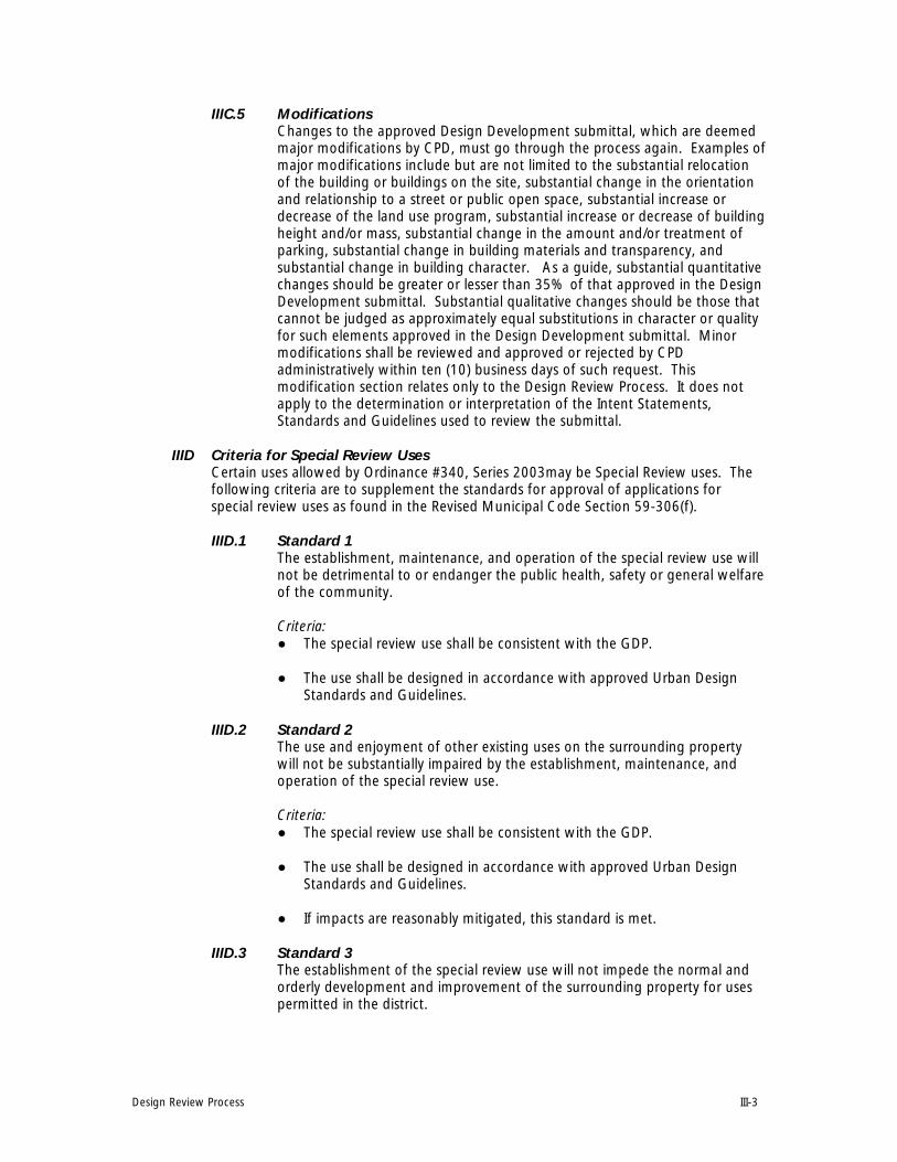
Design Review Process III-3
IIIC.5 Modifications Changes to the approved Design Development submittal, which are deemed major modifications by CPD, must go through the process again. Examples of major modifications include but are not limited to the substantial relocation of the building or buildings on the site, substantial change in the orientation and relationship to a street or public open space, substantial increase or decrease of the land use program, substantial increase or decrease of building height and/or mass, substantial change in the amount and/or treatment of parking, substantial change in building materials and transparency, and substantial change in building character. As a guide, substantial quantitative changes should be greater or lesser than 35% of that approved in the Design Development submittal. Substantial qualitative changes should be those that cannot be judged as approximately equal substitutions in character or quality for such elements approved in the Design Development submittal. Minor modifications shall be reviewed and approved or rejected by CPD administratively within ten (10) business days of such request. This modification section relates only to the Design Review Process. It does not apply to the determination or interpretation of the Intent Statements, Standards and Guidelines used to review the submittal.
IIID Criteria for Special Review Uses Certain uses allowed by Ordinance #340, Series 2003may be Special Review uses. The following criteria are to supplement the standards for approval of applications for special review uses as found in the Revised Municipal Code Section 59-306(f).
IIID.1 Standard 1 The establishment, maintenance, and operation of the special review use will not be detrimental to or endanger the public health, safety or general welfare of the community.
Criteria: ● The special review use shall be consistent with the GDP.
● The use shall be designed in accordance with approved Urban DesignStandards and Guidelines.
IIID.2 Standard 2 The use and enjoyment of other existing uses on the surrounding property will not be substantially impaired by the establishment, maintenance, and operation of the special review use.
Criteria:● The special review use shall be consistent with the GDP.
● The use shall be designed in accordance with approved Urban DesignStandards and Guidelines.
● If impacts are reasonably mitigated, this standard is met.
IIID.3 Standard 3 The establishment of the special review use will not impede the normal and orderly development and improvement of the surrounding property for uses permitted in the district.
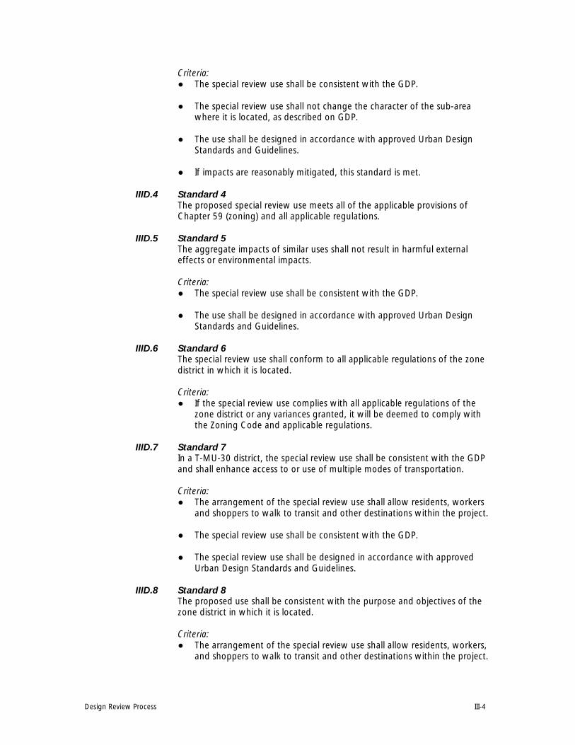
Design Review Process III-4
Criteria:● The special review use shall be consistent with the GDP.
● The special review use shall not change the character of the sub-areawhere it is located, as described on GDP.
● The use shall be designed in accordance with approved Urban DesignStandards and Guidelines.
● If impacts are reasonably mitigated, this standard is met.
IIID.4 Standard 4 The proposed special review use meets all of the applicable provisions of Chapter 59 (zoning) and all applicable regulations.
IIID.5 Standard 5 The aggregate impacts of similar uses shall not result in harmful external effects or environmental impacts.
Criteria:● The special review use shall be consistent with the GDP.
● The use shall be designed in accordance with approved Urban DesignStandards and Guidelines.
IIID.6 Standard 6 The special review use shall conform to all applicable regulations of the zone district in which it is located.
Criteria:● If the special review use complies with all applicable regulations of the
zone district or any variances granted, it will be deemed to comply withthe Zoning Code and applicable regulations.
IIID.7 Standard 7 In a T-MU-30 district, the special review use shall be consistent with the GDP and shall enhance access to or use of multiple modes of transportation.
Criteria:● The arrangement of the special review use shall allow residents, workers
and shoppers to walk to transit and other destinations within the project.
● The special review use shall be consistent with the GDP.
● The special review use shall be designed in accordance with approvedUrban Design Standards and Guidelines.
IIID.8 Standard 8 The proposed use shall be consistent with the purpose and objectives of the zone district in which it is located.
Criteria:● The arrangement of the special review use shall allow residents, workers,
and shoppers to walk to transit and other destinations within the project.

Design Review Process III-5
● The special review use shall be consistent with the GDP.
● The special review use shall be designed in accordance with approvedUrban Design Standards and Guidelines.
IIID.9 Standard 9 The proposed special review use shall be sited and designed to be compatible with adjacent uses.
Criteria:● The special review use shall be designed in accordance with approved
Urban Design Standards and Guidelines.
IIID.10 Standard 10 The potential impacts of the proposed special review use will be adequately mitigated.
Criteria:● The special review use shall be consistent with the GDP.
● The special review use shall be designed in accordance with approvedUrban Design Standards and Guidelines.
End of Belleview Station Design Review Process
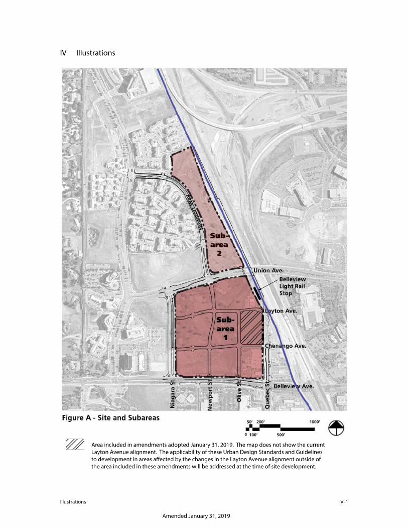
1-VI snoitartsullI
IV Illustrations
Amended January 31, 2019
Area included in amendments adopted January 31, 2019. The map does not show the current Layton Avenue alignment. The applicability of these Urban Design Standards and Guidelines to development in areas a�ected by the changes in the Layton Avenue alignment outside of the area included in these amendments will be addressed at the time of site development.
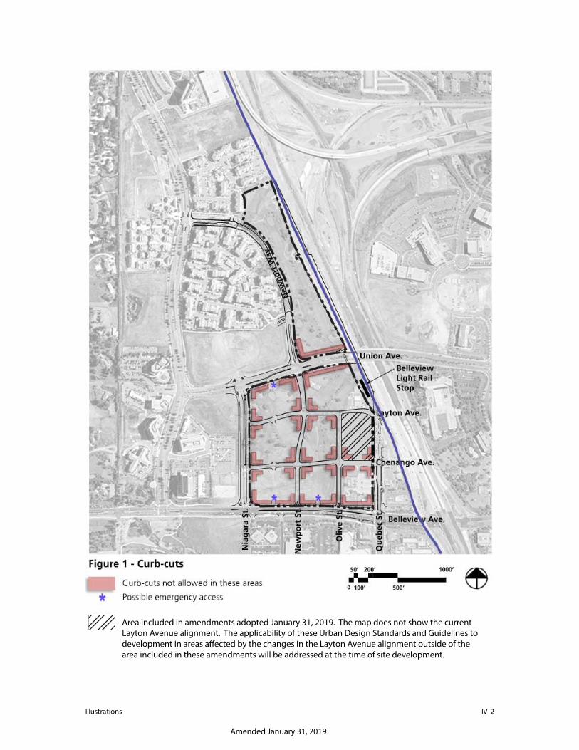
2-VI snoitartsullI
Amended January 31, 2019
Area included in amendments adopted January 31, 2019. The map does not show the current Layton Avenue alignment. The applicability of these Urban Design Standards and Guidelines to development in areas a�ected by the changes in the Layton Avenue alignment outside of the area included in these amendments will be addressed at the time of site development.

Area included in amendments adopted January 31, 2019. The pedestrian amenity zone with special streetscape designation located on Quebec Street shall only apply to:• Areas of zone lots north of the southernmost zone lot abutting Quebec Street in the highlighted area;
and• All areas of zone lots abutting a street, public right-of-way, or property owned by the City and
County of Denver in the highlighted area.The map does not show the current Layton Avenue alignment. The applicability of these Urban Design Standards and Guidelines to development in areas a�ected by the changes in the Layton Avenue alignment outside of the area included in these amendments will be addressed at the time of site development.
IV-3Illusrations
Amended January 31, 2019
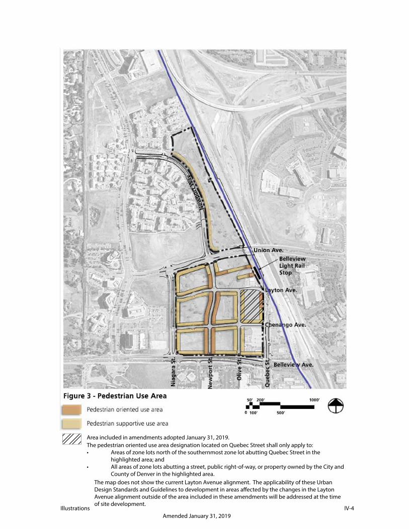
IV-4Illustrations
Area included in amendments adopted January 31, 2019.The pedestrian oriented use area designation located on Quebec Street shall only apply to:• Areas of zone lots north of the southernmost zone lot abutting Quebec Street in the
highlighted area; and • All areas of zone lots abutting a street, public right-of-way, or property owned by the City and
County of Denver in the highlighted area.
Lorem ipsum
Amended January 31, 2019
The map does not show the current Layton Avenue alignment. The applicability of these Urban Design Standards and Guidelines to development in areas a�ected by the changes in the Layton Avenue alignment outside of the area included in these amendments will be addressed at the time of site development.

Amended January 31, 2019
Area included in amendments adopted January 31, 2019. The map does not show the current Layton Avenue alignment. The applicability of these Urban Design Standards and Guidelines to development in areas a�ected by the changes in the Layton Avenue alignment outside of the area included in these amendments will be addressed at the time of site development.
IV-5Illustrations

Illustrations IV-6

Illustrations IV-7
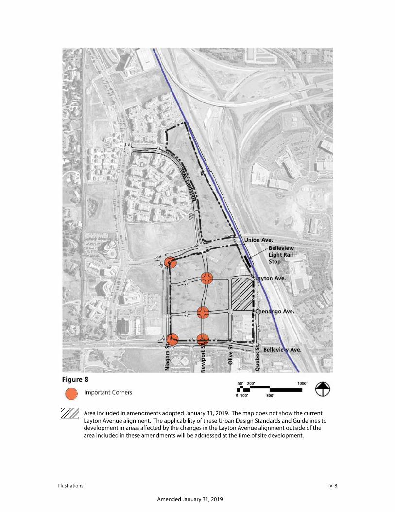
8-VI snoitartsullI
Amended January 31, 2019
Area included in amendments adopted January 31, 2019. The map does not show the current Layton Avenue alignment. The applicability of these Urban Design Standards and Guidelines to development in areas a�ected by the changes in the Layton Avenue alignment outside of the area included in these amendments will be addressed at the time of site development.
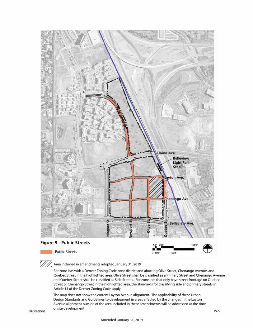
IV-9Illusrations
Area included in amendments adopted January 31, 2019
For zone lots with a Denver Zoning Code zone district and abutting Olive Street, Chenango Avenue, and Quebec Street in the highlighted area, Olive Street shall be classi�ed as a Primary Street and Chenango Avenue and Quebec Street shall be classi�ed as Side Streets. For zone lots that only have street frontage on Quebec Street or Chenango Street in the highlighted area, the standards for classifying side and primary streets in Article 13 of the Denver Zoning Code apply.
Amended January 31, 2019
The map does not show the current Layton Avenue alignment. The applicability of these Urban Design Standards and Guidelines to development in areas a�ected by the changes in the Layton Avenue alignment outside of the area included in these amendments will be addressed at the time of site development.

Illustrations IV-10

Illustrations IV-11

Illustrations IV-12
End of Belleview Station Illustrations