bell system practices section 591-048-200 …bell system practices at&tco standard section...
TRANSCRIPT

BELL SYSTEM PRACTICES AT&TCo Standard
SECTION 591-048-200 Issue 1, January 1980
DATA SET 113AR-L1B
INSTALLATION AND CONNECTIONS
CONTENTS PAGE • Grandfathered DS 113A may be connected
1.
2.
GENERAL
OPTIONS
in registered arrangements provided the interface with the network is made with the appropriate jack and cord as shown in Fig. 4.
3. INTERFACE LEADS 3 • Data set 113AR may be connected in grandfathered arrangements provided the
4. INSTALLATION 3 interface with the network is made with the appropriate cords as shown in Fig. 4.
5. CONNECTIONS 3 • Connections to the telephone lines must be
6. INSTALLATION TEST 3 made with the proper cords to the voice or data jack as shown in Fig. 4.
7. REFERENCES 3
1. GENERAL
1.01 This section describes the procedure to be followed for the installation of data set (DS)
113AR-L1B (Fig. 1).
1.02 Whenever this section is reissued, the reason for reissue will be contained in this paragraph.
1.03 Data set 113AR-L1B is the registered replacement for the older DS 113A-type and
maintains the same capabilities. Data set 113AR-L1B meets the requirements of the FCC Registration Program and is compatible with all DSs 103-type, 113B, 113D, and 113DR. Data set 113AR-L1B is also compatible with DSs 212A and 212AR when operating in the low-speed mode. The registration number forDS 113AR-L1B is AS593M-62999-MD-E.
1.04 General information concerning registered data sets and arrangements follows.
• Registered versions of data sets are coded with an "R" in the data set code.
• All Bell System switched network data sets not coded with an "R" in the data set code are grandfathered.
1.05 Data set 113AR-L1B must be located within range of the customer-provided interface
cable. This cable should not exceed the Electronic Industries Association (EIA) recommendation of 50 feet.
1.06 A 25-pin connector is provided at the rear of the data set for connection to the
customer-provided equipment (CPE). This connector is designed to connect to a customer-provided Cinch or Cannon DB-19604-432 plug equipped with a DB-51226-1 hood, or equivalent.
1.07 Data set 113AR-L1B obtains its power from an externally mounted transformer. The
customer must furnish a standard 105- to 129-volt, 57- to 63-Hz ac power outlet that will accept a plug equipped with two parallel blades.
Note: The ac outlet must not be under the control of a switch.
2. OPTIONS
2.01 Data set 113AR-L1B has options that must be installed prior to placing the data set in
service. These options, which should be specified on the service order, affect the control of the DATA lamp in the associated telephone set and
NOTICE Not for use or disclosure outside the
Bell System except under written agreement
Printed in U.S.A. Page 1

SECTION 59 1-048-200
Fig . 1-DS 113AR-L1 8
the CD interface circuit. The options are summarized m Table A and described as follows.
• When option X is provided, the DATA lamp lights when the data set is in the data mode. This option also enables the CPE to disconnect the data set automatically.
• When option V is provided, the DATA lamp lights when the data set is in the data
Page 2
mode. The data set must be disconnected manually.
• When option W is provided, the DATA lamp does not light and the data set must be disconnected manually.
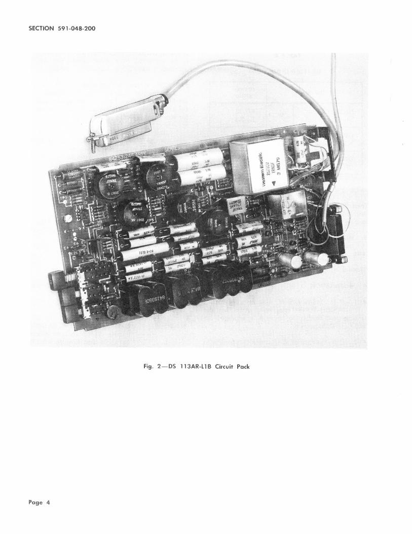
2.02 The options are installed by properly inserting two plug-in option straps in the circuit pack.
Refer to Table A for the terminal assignments

TABLE A
DS 113AR-l1 BOPTIONS
OPTION OPTION STRAP
No Data Lamp w E5-E6 No CD Control El-E3
Data Lamp v E4-E6 No CD Control El-E3
Data Lamp X
E4-E6 CD Control E2-E3
and to Fig. 2 for their locations on the circuit pack. The circuit pack should be removed and replaced from the rear of the housing. The circuit pack is held in position by the latching mechanism shown in Fig. 3.
3. INTERFACE LEADS
3.01 Data set 113AR-L1B provides the customer with the interface leads listed in Table B.
These leads are similar to EIA Standard RS-232-C.
4. INSTALLATION
4.01 If DS 113AR-L1B is being installed with a TOUCH-TONE® telephone, verify that the
transmission facility to be used is arranged for TOUCH-TONE service.
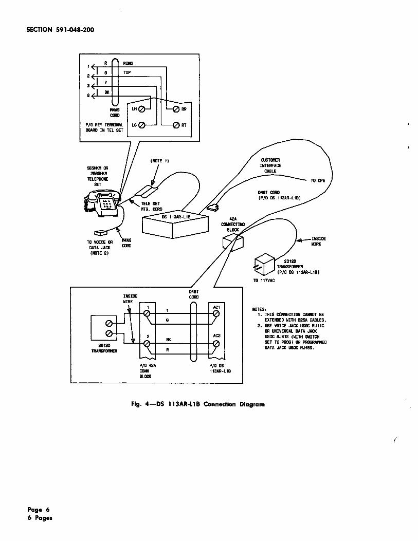
4.02 Place the data set in a location that facilitates connection to the CPE interface cable,
transmission facility, and an ac power outlet. Refer to Fig. 4 for general installation information.
4.03 The 565HKM or 2565HKM telephone set requires the following modification to work
with DS 113AR-L1B.
• Remove BR wire from terminal N on terminal board and connect to terminal EH on network.
5. CONNECTIONS
5.01 The transmit level of DS 113AR-L1B is fixed at a level not to exceed -9 dBm under any
ISS 1, SECTION 591-048-200
operating condition. Data set 113AR-L1B is designed to be connected to a basic access line having parameters specified in Section 314-205-501.
5.02 The station arrangement shown in the connection diagram (Fig. 4) complies with
the FCC Registration Program and applies only to DS 113AR-L1B. The following parts are required for this arrangement.
Data set 113AR-L1B 2012D Transformer-supplied with data set D4BT Cord-supplied with data set M4AS Cord-supplied with data set 565HKM or 2565HKM Telephone Set 42A Connecting Block
6. INSTALLATION TEST
6.01 After installation is completed, the data set should be tested to determine if it is operating
properly. Refer to Section 591-048-500.
7. REFERENCES
7.01 The following BSPs provide additional information:
SECTION
314-205-501
590-010-200
590-101-103
591-048-100
591-048-500
TITLE
Data Systems-DATAPHONE® Service-Direct Distance Dialing Network-Test Requirements for Subscriber, Foreign Exchange, and Remote Exchange Lines
Data Sets and Data Access Arrangements-General Installation and Connection Information
Jacks for Registered Data Equipment-Single and Multiline Installations
Data Set 113AR-L1B-Description and Operation
Data Set 113AR-L1B-Test Procedure
Page 3
Page 4
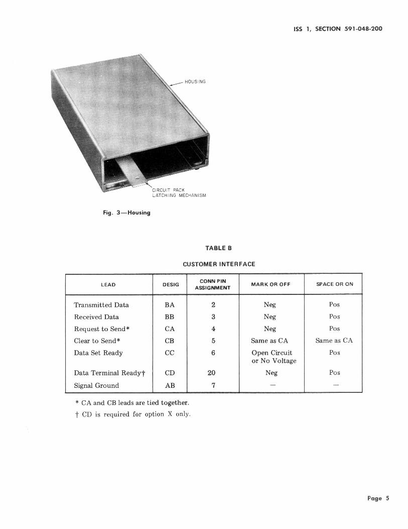
Fig . 3 - Housing
CIRCUIT PACK LATCHING MECHANISM
TABLE B
ISS 1, SECTION 591-048-200
CUSTOMER INTERFACE
LEAD DESIG
Transmitted Data BA
Received Data BB
Request to Send* CA
Clear to Send* CB
Data Set Ready cc
Data Terminal Readyt CD
Signal Ground AB
* CA and CB leads are tied together.
t CD is required for option X only.
CONN PIN ASSIGNMENT
2
3
4
5
6
20
7
MARK OR OFF SPACE OR ON
Neg Pos
Neg Pos
Neg Pos
Same as CA Same as CA
Open Circuit Pos or No Voltage
Neg Pos
- -
Page 5
SECTION 591-048-200
R RING
G TIP 2~--~~-----------,
3~--~~----------,
8~---~r----~~~J
!MAS CORD
P /0 KEY TEMINAL BOARD IN TEL SET
585ll<fl IR 2585ll<fl
TELEPHONE SET
P/0 42A COlli BLOCK
----
P/0 DS 113AR-L 18
NOTES: 1. THIS CONNECTION CANNOT BE
EXTEI'IIED WITH B25A CABLES. 2. USE VOICE JACK USOC RJ11C
IR UNIVERSAL DATA JACK IJSOC RJ41S (WITH SWITCH SET TO PROS) IR PROBRAI'IIED DATA JACK USOC RJ45S.
Fig. 4-DS 113AR-L 18 Connection Diagram
Page 6 6 Pages
(