bell 525 flight test accident bell helicopter party ... · regulations part 91. visual...
TRANSCRIPT
Bell 525 Flight Test Accident
Bell Helicopter Party Submission
DCA 16FA199
Bell Helicopter Textron Inc.
Bell 525 Serial Number 62001
N525TA
Italy, Texas
6 July 2016
ii
Bell Helicopter Party Submission
© 2017 Bell Helicopter Textron Inc.
Bell Helicopter Textron Inc.
Bell 525 Serial Number 62001
N525TA
Italy, Texas
6 July 2016
iii
TABLE OF CONTENTS
Page
List of Figures ................................................................................................................................ iv
List of Tables ................................................................................................................................. iv
References ........................................................................................................................................v
1. Executive Summary .................................................................................................................1
2. Accident Investigation and Analysis ........................................................................................3
2.1 The Accident .......................................................................................................................3
2.2 Test Crew ............................................................................................................................5
2.2.1 Pilot in Command ........................................................................................................5
2.2.2 Co-Pilot ........................................................................................................................6
2.2.3 Telemetry (TM) Room .................................................................................................6
2.2.4 The Chase Aircraft and Crew .......................................................................................7
2.3 Environmental Conditions ..................................................................................................7
2.4 The 525 Program ................................................................................................................7
2.4.1 The 525 Aircraft ...........................................................................................................8
2.4.2 The Test Aircraft ..........................................................................................................8
2.5 Flight Test Processes and Preparation ................................................................................9
2.5.1 Bell Flight Test ............................................................................................................9
2.5.2 Day of Activities ........................................................................................................10
3. Accident Scenario Analysis ...................................................................................................12
3.1 Control Filtering ...............................................................................................................23
4. Conclusions ............................................................................................................................25
5. Going forward ........................................................................................................................26
iv
LIST OF FIGURES
Page
Figure 1. Test Aircraft Flight Path and Wreckage Location. (image courtesy NTSB) .............. 4
Figure 2. Accident Aircraft Debris Field. (image courtesy NTSB) ............................................ 5
Figure 3. Completed Envelope Expansion in Terms of Airspeed and Altitude, up to Day of
Accident. .......................................................................................................................
Figure 4. Time history of accident record, showing control inputs, rotor response, and pilot
seat vibration level. ................................................................................................... 14
Figure 5. Test records 48 and 50, just prior to the accident record (51), showing rotor RPM
recovery to 103% RPM with modulation of collective control. ............................... 15
Figure 6. Pilot seat vertical vibration with band pass filter showing 6 Hz signal content. ...... 16
Figure 7. Aircraft pitch attitude change (right Axis) coincided with increased vibration and
may have led the pilot to apply forward cyclic during the accident record............... 16
Figure 8. Airframe, Main Rotor, and Tail Rotor dynamic modes predicted and measured
during the accident record. ........................................................................................ 19
Figure 9. Illustration of the airframe first vertical bending mode (with highly exaggerated
displacement) shows the forward cabin motion as primarily up and down, while
the main rotor mast pitches fore/aft. ........................................................................ 20
Figure 10. Modal frequencies of the Airframe, Main Rotor, and Tail Rotor with amplitude
of Pilot seat vertical vibration. .................................................................................. 21
Figure 11. Biomechanical feedback of the collective control is inhibited by collective rate
limiting enforced by the control laws. Rate limiting reduced the oscillatory
collective input applied at the main rotor actuators and appeared to dampen the
feedback cycle, reducing pilot seat vibration. ........................................................... 24
LIST OF TABLES
Page
Table 1. Flight Test Risks Identified for Test Flight 184 ............................................................. 11

v
REFERENCES
[1] National Transportation Safety Board (NTSB), "NTSB No. DCA16FA199, 6 July 2016,
Performance Study, Specialists Report," NTSB, Office of Research and Engineering,
Washington, D. C..
[2] National Transportation Safety Board (NTSB), "NTSB No. DCA16FA199, 6 July 2016,
Airworthiness Group Chairman's Factual Report," NTSB, Office of Aviation Safety,
Washington, DC, 2017.

1
1. EXECUTIVE SUMMARY
On 6 July 2016, Bell Helicopter experienced the tragic loss of a prototype 525 helicopter,
N525TA and its crew. The flight originated from the Arlington Municipal Airport (KGKY), as a
developmental test flight and was conducted under the provisions of Title 14 Code of Federal
Regulations Part 91. Visual Meteorological Conditions (VMC) prevailed at the time of the
accident. In the months since the accident, a small team of Bell flight technology engineers,
pilots, and flight test specialists have worked with NTSB investigators to determine the cause of
the in-flight breakup near Italy, Texas.
The accident flight was a part of the company developmental test program to develop the 525
aircraft. The program consists of three development and envelope expansion (D&EE) aircraft.
N525TA was aircraft number 1 in the test program. Due to the aircraft being a D&EE test
vehicle, telemetry (TM) data streaming and on-board instrumentation and data capture devices
provided a very large quantity of useful analysis data. Neither the cockpit voice recorder (CVR)
nor TM cockpit voice channel were operative, so there is no voice or audio data from the test
aircraft.
On the day of the accident, the twin engine helicopter was demonstrating the ability to recover
from a single engine failure at a high airspeed, high power flight condition. Upon initiating the
single engine simulation, the main rotor rotational speed (RPM) decelerated as expected. The
crew lowered the collective control to reduce the power demanded by the rotor, initiating a
recovery of the rotor RPM. The rotor RPM decay was arrested but not restored. While
remaining at this low RPM, high airspeed condition, an unexpected vibration emerged.
The cabin vibration was amplified in a biomechanical feedback loop involving involuntary
oscillations of the pilot collective control. Sensors utilized to stabilize the helicopter in gusts and
maneuvers also participated in the feedback. This vibration grew rapidly as the aircraft
continued to operate in a high airspeed, low rotor RPM condition outside the steady operating
envelope of the aircraft. Approximately 21 seconds after the start of the test, amid a continued
high vibratory environment, large control inputs coincided with the main rotor blades departing
from their normal plane of motion, and the tailboom was severed. An inflight breakup of the
aircraft ensued. Prior to the tailboom strike, the flight data indicates that the aircraft responded
as expected to control inputs and there were no indications of structural or system failures.
The accident can be summarized as follows:
While at a high airspeed test point, a sustained low rotor RPM allowed for the development of
high vibration throughout the aircraft. The high vibratory environment led to adverse control
inputs that reduced the rotor RPM to critical levels and resulted in high flapping of the rotor
blades. A near full aft cyclic control input led to one of the rotor blades severing the tail boom
and loss of control of the aircraft.
2
Going forward, several changes to the aircraft are being implemented. In particular, the
biomechanical and sensor feedback will be filtered by the control system so that these
undesirable control inputs are not passed to the main rotor swashplate actuators, thereby
preventing amplification of the vibrations present in this flight condition. The flight test program
will assess filter effectiveness through a carefully planned approach as part of the completion of
the remaining envelope expansion and certification testing.
3
2. ACCIDENT INVESTIGATION AND ANALYSIS
2.1 The Accident
At Bell Helicopter, test points are identified by the associated test (flight) number and the
sequence in which test points are acquired, called the record number. The inflight breakup
occurred during Test number 184 (Approximately the 184th flight of the test aircraft), and record
51 (Approximately the 51st test point planned for the day). The test point for record 51 was a
simulated single engine failure test point at high forward speed. Upon initiating the simulated
engine failure, main rotor RPM dropped to around 92% of nominal, and a vibration build-up
occurred. The vibration led to control system feedback and excessive cabin vibration. As
detailed in Section 3, "Accident Scenario Analysis," large control inputs resulted in significant
main rotor blade flapping manifested when rotor rotational speed decayed below 80%.
Approximately twenty-one seconds after record 51 began, a main rotor blade severed the
tailboom from the aircraft.
The test aircraft’s flight path for record 51 was approximately 320 degrees, according to GPS
data. The test aircraft began the maneuver for Record 51 at approximately 3,000 – 3200 MSL.
Record 51 was the last high speed test point for the given altitude. As the test aircraft nosed over
to obtain the required airspeed, the chase aircraft positioned on the right side of the test aircraft.
About 12-seconds into the test point, a “knock-it-off” call was transmitted over the radio by the
TM room. An engineer at a TM monitoring station had observed high vibration in the test
aircraft. The knock-it-off communication calls for the test pilot to restore the helicopter to a safe
condition. The chase crew, consisting of a pilot and copilot, then observed the nose of the test
aircraft come up slightly in an apparent attempt to “knock-it-off” and execute a deceleration.
Additionally, the chase crew observed that the rotor system appeared to become “out of phase”
with the airframe with one blade appearing to be flying significantly higher than the other four
blades. The chase pilot then reported seeing the tailboom flex down and then back up, with the
tailboom folding up and drifting away from the remainder of the aircraft. The chase aircraft then
executed maneuvers to stay clear of the debris. As the test aircraft rotated, the aircraft began to
break apart with the larger pieces continuing forward along the original flight path. Shortly after
the test aircraft yawed left, the trajectory became steeper, with the test aircraft impacting the
terrain left wing down.
Figure 1 shows the test aircraft’s flight path for record 51. Each point is annotated with the time
in seconds from the start of record 51 and with the corresponding height above ground in feet.
The test record began at time zero, in the lower right of the figure. The telemetry system stopped
recording data at approximately the 21 second mark. The test aircraft’s last verified position is
shown as "last point" in Figure 1 (from Reference [1]).

4
Figure 1. Test Aircraft Flight Path and Wreckage Location. (image courtesy NTSB)
The main wreckage field was 2,200 ft from the last transmitted GPS point, along the flight path
heading of 320°. The wreckage was distributed into two distinct areas. The main wreckage site
was comprised of an impact crater, remnants of the main fuselage, cockpit, transmission and
main rotor hub, two of the five main rotor blades, the forward portion of the tailboom, and both
engines. There was evidence of a post-crash fire at the main wreckage site. The wreckage debris
path at the main wreckage site, about 200 feet in length, was oriented along the 315-degree
magnetic bearing. The second distinct wreckage site, about 1,300 feet southeast of the main
wreckage site, comprised the aft portion of the tailboom. The aft portion of the tailboom
contained two of the tail rotor drive shafts, the intermediate gearbox (IGB), tail rotor gearbox
(TRGB), and tail rotor hub assembly with all four blades and dampers attached.
Three of the five main rotor blades were found separate from the main and secondary wreckage
sites. Various pieces of forward cowlings, cockpit frames, and cabin doors were found in a
debris path between the main and secondary wreckage sites. Additionally, lightweight debris,
such as insulation and main rotor blade skin pieces, were found scattered to the northeast of the
debris path between the main and secondary wreckage sites, with the furthest piece being found
5
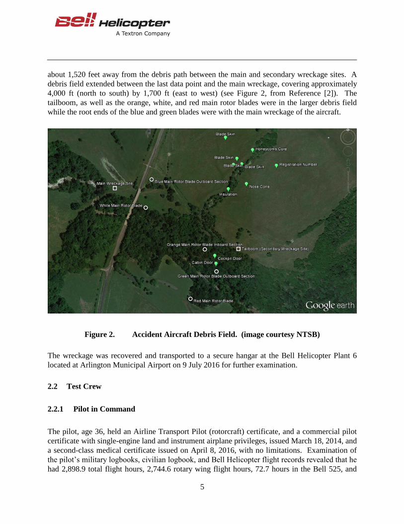
about 1,520 feet away from the debris path between the main and secondary wreckage sites. A
debris field extended between the last data point and the main wreckage, covering approximately
4,000 ft (north to south) by 1,700 ft (east to west) (see Figure 2, from Reference [2]). The
tailboom, as well as the orange, white, and red main rotor blades were in the larger debris field
while the root ends of the blue and green blades were with the main wreckage of the aircraft.
Figure 2. Accident Aircraft Debris Field. (image courtesy NTSB)
The wreckage was recovered and transported to a secure hangar at the Bell Helicopter Plant 6
located at Arlington Municipal Airport on 9 July 2016 for further examination.
2.2 Test Crew
2.2.1 Pilot in Command
The pilot, age 36, held an Airline Transport Pilot (rotorcraft) certificate, and a commercial pilot
certificate with single-engine land and instrument airplane privileges, issued March 18, 2014, and
a second-class medical certificate issued on April 8, 2016, with no limitations. Examination of
the pilot’s military logbooks, civilian logbook, and Bell Helicopter flight records revealed that he
had 2,898.9 total flight hours, 2,744.6 rotary wing flight hours, 72.7 hours in the Bell 525, and
6
40.1 hours flown within the previous 30 days. He held a Letter of Authorization (LOA) from the
Federal Aviation Administration dated December 2, 2015, authorizing him to act as pilot-in-
command of the Bell Helicopter experimental helicopter designated model 525. His most recent
flight review was conducted on October 29, 2015, flown in a twin engine Bell 430 helicopter.
He completed Crew Resource Management (CRM) training January 12, 2015. The pilot received
his Bachelor of Science degree in electrical engineering from the United States Naval Academy
in 2002, and graduated from the United States Naval Test Pilot School (USNTPS) in 2010. After
USNTPS he worked on numerous flight test projects involving the AH-1W and UH-1Y
helicopters. On September 23, 2013 he joined the Flight Test Department of Bell Helicopter.
His primary responsibility was being an experimental test pilot on the Bell 525 program.
2.2.2 Co-Pilot
The copilot, age 43, held an Airline Transport Pilot (rotorcraft) certificate, and a commercial
certificate with single-engine land, multi-engine land, and instrument airplane ratings, issued
October 15, 2014, and a second-class medical issued on May 31, 2015, with no limitations.
Examination of the pilot’s military logbooks, civilian logbooks and Bell Helicopter flight records
revealed that he had 3,957.5 total flight hours, 2,589.4 rotary wing hours, 84.1 hours in the Bell
525, and 27.4 flight hours within the previous 30 days. He held a Letter of Authorization (LOA)
from the Federal Aviation Administration dated December 2, 2015, authorizing him to act as
pilot-in-command of the Bell Helicopter experimental helicopter designated model 525. His
most recent flight review was conducted on November 6, 2015, flown in a Bell 407. He also
completed a flight review in the twin engine Bell 430, October 6, 2015. Crew Resource
Management (CRM) training was completed on January 12, 2015. The copilot received a
Bachelor of Science degree from Texas Tech University in 1996, and completed US Navy flight
training in 2000. In 2006 he graduated from the USNTPS and proceeded to work on numerous
AH-1W and UH-1Y test programs. He joined the Bell Helicopter Flight Test Department on
August 2, 2010. His primary responsibility was being an experimental test pilot on the Bell 525
program.
2.2.3 Telemetry (TM) Room
The TM room consists of multiple monitoring stations whose purpose is to provide real time
observation of direct and derived parameters streamed from the aircraft to the TM room. During
record 51, there were 9 stations being manned: The Test Director, Rotor Dynamics, Control
Laws (CLAWs), Flight Control Systems, Structural Dynamics, Handling Qualities (HQ), Data
Operations, Loads and the Telemetry Room Operator. These specialists are integral participants
in ensuring the safe conduct of flight test. All TM personnel have the authority to stop a data
point or an entire flight if a parameter exceeds a pre-determined value or if there is something out
of the ordinary. The Test Director is the only one who has direct communication with the
aircraft, but each member has the ability and duty to call a “knock-it-off” if either of these events
were to occur.
7
2.2.4 The Chase Aircraft and Crew
The chase aircraft utilized on the day of the mishap was a Bell 429 helicopter. Two Bell pilots
were in the aircraft. Their primary duties were to monitor the test area for other aircraft, monitor
the flight for safety issues and observe the flight test vehicle as it executed the test card. The
chase aircraft was in radio communication with both the test vehicle and the TM room. The PIC
is a USNTPS graduate and experienced test pilot. The co-pilot is a Rotorcraft ATP and graduate
of USN Post Graduate School Aviation Safety Course. At the higher speeds required for some
test points, the 429 aircraft is unable to keep up with the test vehicle and is more of an area chase
for those points. This is acceptable with proper in-flight planning and adjustments in space prior
to commencing a test point at the higher speeds.
2.3 Environmental Conditions
The closest weather reporting location to the accident site was Mid-Way Regional Airport
(KJWY), located approximately 12 miles north of the accident. The airport had an Automated
Weather Observation System (AWOS). The following conditions were reported near the time of
the accident: 1155 CDT, automated, wind from 180° at 15 knots gusting to 20 knots, visibility 10
statute miles, scattered clouds at 3,000 feet AGL, temperature 32° C, dew point temperature 24°
C, altimeter 29.97 inches of mercury (Hg). The observation provided a calculated relative
humidity of 63%, a station pressure of 29.19 inches Hg, with a density altitude of 3,175 feet. No
precipitation was recorded at the station.
Additional weather reporting in the general vicinity was from Hillsboro Municipal Airport
(KINJ) located 15 miles SSW of the accident site. At 1156 CDT METARS reported temperature
as 31°C (87°F) with a dew point of 23°C (73°F) and an altimeter setting of 29.98. Visibility 10
statute miles with scattered clouds at 3,000 ft. Winds were reported at 14 knots from 170°,
gusting to 22 knots.
Based on interviews with the chase pilots and the TM crew there had been discussion about the
air quality during the conduct of the test. The team had short discussions on the matter and
decided that the air quality was sufficient to continue with the test flight. The accident occurred
on a second attempt at this data point as the first attempt was discontinued due to the test aircraft
encountering a thermal or choppy/turbulent conditions. Environmental conditions of the day are
not deemed to be contributory to the accident.
2.4 The 525 Program
The Bell 525 program is a type certification program of a new type design helicopter. The
aircraft is designed as a transport category helicopter for the super medium twin helicopter
market. The originally planned test program consisted of 5 test vehicles; 3 dedicated D&EE

8
aircraft and 2 dedicated production representative aircraft. The accident aircraft was 525 number
1 and was one of the D&EE aircraft. At the time of the accident, the program had flown the three
D&EE test aircraft and had accumulated a total of approximately 300 hours of flight time with
over 140 hours of ground test activity.
2.4.1 The 525 Aircraft
The Model 525 aircraft features a five bladed main rotor, canted four bladed tail rotor, composite
airframe, a triple redundant Fly-By-Wire (FBW) Flight Control System (FCS), a Garmin
G5000H Integrated Flight Deck, a Honeywell RE100BR Auxiliary Power Unit (APU) and two
General Electric (GE) CT7-2F1 engines. Additionally, the aircraft was equipped with retractable
tricycle landing gear. The aircraft is designed to carry 16 passengers and a crew of two at a
cruise speed of 155 knots and operate up to an altitude of 20,000 ft at a maximum takeoff weight
of 20,500 lbs.
The 525 Integrated Flight Deck is configured with two pilot stations and a console between the
seats. Each pilot station has a cyclic side stick controller forward of the seat’s right armrest and a
collective side stick controller immediately forward of the seat’s left arm rest. Each pilot has a
set of directional (anti-torque) pedals forward of the seat. The instrument panel consists of four
identical primary flight displays. The center console consists of two Garmin Touch Control
(GTC) panels, landing gear handle, and Nav/Com panel. The engine controls, known as the
Crank, Off, Start, Idle, Fly (COSIF) knobs are directly above the GTC’s. There is a single
COSIF knob for each engine.
2.4.2 The Test Aircraft
The test aircraft, serial number (S/N) 62001 was manufactured in 2015 and was the first 525 test
vehicle. It had flown approximately 200 hours prior to the accident flight. As the primary
D&EE air vehicle, the test aircraft was instrumented to capture 3000 measurements and 5200
parameters, including derived readings. Each parameter was sampled and recorded by the data
system between 31 and 1000 times per second (Hz). These data were both recorded and stored
on the onboard flight test recorder system, as well as transmitted via TM to the ground station at
the Bell flight test facility.
At the time of the accident, the test aircraft was configured for a heavy gross weight
(approximately 19,975 pounds) and a forward center of gravity (CG). In addition to the standard
Flight Deck configuration, the test aircraft was configured with a Flight Test Switch Panel
located on the center console. Among other items, this panel included controls for the One-
Engine-Inoperative (OEI) special training mode. Additionally, outboard of the instrument panel,
each pilot had a pilot display unit (PDU) that provided a limited number of real time flight test
instrumentation parameters.
9
2.5 Flight Test Processes and Preparation
2.5.1 Bell Flight Test
Bell has a robust D&EE test process that includes not only test and evaluation at the aircraft
level, but also test and evaluation of the individual components and systems. The use of
analytical and physical tools to test and analyze components, systems, and systems-of-systems
are prerequisite to air vehicle ground and flight test. Risk analysis and management is initiated
early in the process and iterated upon as the vehicle and systems change or as more is learned
from test and evaluation activities. Risk analysis and management is an integral component of
the development and flight test process.
2.5.1.1 Systems Integration Lab (SIL)
Bell Helicopter typically utilizes an engineering SIL to evaluate both software and certain
hardware prior to items being introduced to flight test. The specific SIL for the 525 program is
the Relentless Advanced Systems Integration Lab (RASIL). The RASIL consists of an accurate
engineering representation of the cockpit, including control feel and visual in-flight
representation projected on a wrapped screen. Next to the RASIL cockpit is a room containing
actual flight hardware rigged to apply flight loads into engineering representations of related
hardware. Control movements in the cockpit cause the corresponding hardware to respond. The
RASIL is used not only to validate software but also as a training and risk mitigation tool as it
allows the pilots to develop flight procedures and pre-fly flight test cards prior to test execution
in the air vehicle.
2.5.1.2 Flight Simulation
Bell utilizes an engineering flight test simulator to assist in the development of cockpit
ergonomics, layout, and control laws. The Bell 525 program utilized the engineering flight
simulator early in the development of the program to assist in designing and evaluating the
overall cockpit layout as well as the initial control law (CLAW) development. These
development activities transitioned to the RASIL once the RASIL was functional.
2.5.1.3 Flight Test Risk Management
Bell Helicopter has a robust Flight Test Risk Management Plan (FTRMP) that is in alignment
with FAA Order 4040.26. The flight test risk management process starts early in a program’s life
cycle and continues until the program is complete. Flight Test Risk Worksheets (FTRW) are
completed for each identified air vehicle test risk. Each identified risk is evaluated and run
through a mitigation process. The final version of the FTRW is approved at the appropriate
10
level, based on the initial risk category. Flight test risks are briefed during the program review
process at the appropriate readiness review for a flight test stage and also at each individual flight
pre-flight briefing where that risk is applicable. Flight test risks are cataloged by program so that
they may be utilized for reference and assist in the identification and mitigation of risk on future
programs.
2.5.1.4 Safety Management System
At the time of the accident Bell was in the process of developing a Safety Management System as
part of the Federal Aviation Administration’s (FAA) Design and Manufacturing Safety
Management System (D&M SMS) Pilot Project. At that time, the plan was to implement an
Aviation Safety Management System (AVSMS) under that umbrella for future acceptance by the
FAA. The tools of an SMS undergoing implementation at the time of the accident were the Just
Culture System, the Confidential Reporting System and the Flight Risk Assessment Tool
(FRAT). The Just Culture Process is not germane to this accident and the Confidential Reporting
Tool was not implemented at the time so neither will be discussed further in this report.
At the time of the accident Bell was in the final stages of implementing a FRAT as part of our
AVSMS. In reviewing the relevant data, there appears to be nothing that would have identified
an elevated risk on this day.
2.5.2 Day of Activities
2.5.2.1 Flight Briefing
Test flight 184 was briefed by the test team at the flight test facility in Arlington, TX at 0600 on
the date of the accident. The purpose of the test was D&EE, specifically: Heavy forward CG
engine load and vibrations at maximum continuous power, heavy forward CG longitudinal roll
spot check, 2 engine to 1 engine simulated engine failures, and run-on landings up to 60 knots.
The test was intended to begin at 0730 but was delayed due to weather concerns. At
approximately 1000, based on the improved weather conditions, the team decided to conduct the
test flight.
2.5.2.2 Flight Test Risks
Two specific flight test risks were identified for test flight 184 (Table 1).

11
Table 1. Flight Test Risks Identified for Test Flight 184
Hazard Mitigation
Rotor speed droops below
safe rotor controllability
speed
Adherence to best practices and approved test procedures
Autorotation practice conducted in the RASIL
Entry conditions will begin in the middle of the weight and
airspeed envelope; build up in GW, airspeed and entry
power levels separately
TM monitoring
Buildup in delay time before pilot response
Execute power recovery procedures before main rotor RPM
is allowed to droop excessively
Transmission and engine
overtorque/overtemp and/or
overspeed due to sudden
increase in power available
Aircrew familiar with Single/Dual Engine Emergency
Procedures
Adherence to best practices and approved test procedures
Evaluation of software in RASIL prior to test
Conduct restrained ground run tests before flight to verify
software functionality
Conduct dual to single points with engine at idle prior to
engine off points
Buildup in airspeed and entry power levels separately
Verify GE Trim file FADEC channel in brief
Dual concurrence before any channel, OEI training
selections
12
3. ACCIDENT SCENARIO ANALYSIS
The accident occurred during a developmental test flight for evaluating recoveries from
simulated single engine failures. In testing, single engine failure is simulated by a Special One
Engine Inoperative (OEI) training mode that permits both engines to run at reduced power levels,
matching the transient and sustained power loss associated with a single engine failure.
Engagement of the OEI training mode is via a touch control panel accessed by the pilot or co-
pilot. The developmental testing on July 6, 2016 was conducted to examine recovery from
simulated single engine failure for the heavy, forward cg, high airspeed portion of the 525 flight
envelope. Below approximately 130 knots, the aircraft is capable of continued flight on one
engine. In the higher speed portion of the flight envelope, power from only a single engine is
insufficient to maintain the flight condition, and consequently the pilot must develop descent rate
and/or reduce speed to initiate recovery. Since engine power for flight is delivered to the main
rotor, a reduction in power available will result in a reduction of rotor rotational speed (RPM).
The pilot manages rotor RPM decay by reducing the main rotor collective control. The main
rotor collective pitch reduction initiates (or increases) the descent rate of the helicopter and
immediately reduces the rotor power required. When the power required is less than the power
available, the rotor RPM can be restored to the full value. For developmental testing on the day
of the accident, the test point was considered complete once the rotor rotational speed achieved
the target value of 103% RPM.
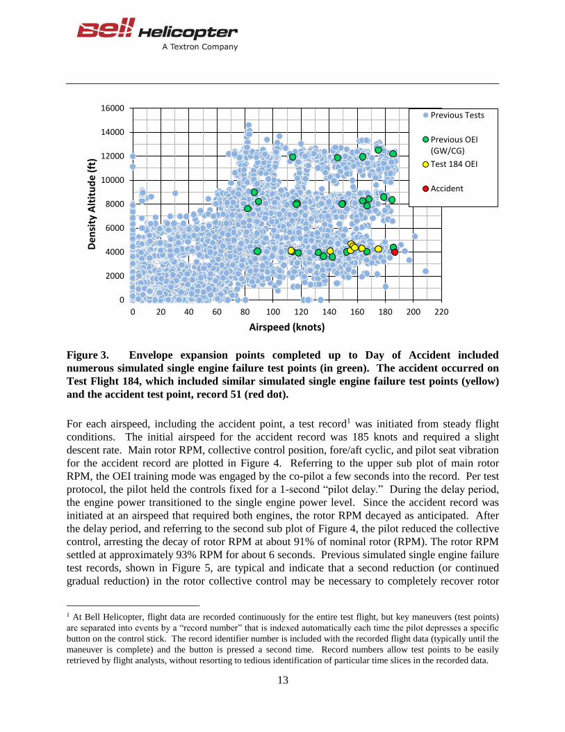
Simulated OEI testing at various altitudes and airspeeds had already been completed for two
cases of aircraft loading (gross weight and center of gravity) as seen by the green points in
. No anomalies were seen. The test aircraft was configured for heavy, forward cg loading on the
day of the accident. Simulated single engine failure testing began at 4000 feet altitude for
increasing airspeeds (10 knot intervals, beginning at 155 knots). Testing progressed to the final
airspeed point for the given altitude when the accident occurred. The accident point is shown as
the red dot in Figure 3.
13
Figure 3. Envelope expansion points completed up to Day of Accident included
numerous simulated single engine failure test points (in green). The accident occurred on
Test Flight 184, which included similar simulated single engine failure test points (yellow)
and the accident test point, record 51 (red dot).
For each airspeed, including the accident point, a test record1 was initiated from steady flight
conditions. The initial airspeed for the accident record was 185 knots and required a slight
descent rate. Main rotor RPM, collective control position, fore/aft cyclic, and pilot seat vibration
for the accident record are plotted in Figure 4. Referring to the upper sub plot of main rotor
RPM, the OEI training mode was engaged by the co-pilot a few seconds into the record. Per test
protocol, the pilot held the controls fixed for a 1-second “pilot delay.” During the delay period,
the engine power transitioned to the single engine power level. Since the accident record was
initiated at an airspeed that required both engines, the rotor RPM decayed as anticipated. After
the delay period, and referring to the second sub plot of Figure 4, the pilot reduced the collective
control, arresting the decay of rotor RPM at about 91% of nominal rotor (RPM). The rotor RPM
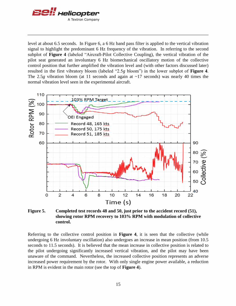
settled at approximately 93% RPM for about 6 seconds. Previous simulated single engine failure
test records, shown in Figure 5, are typical and indicate that a second reduction (or continued
gradual reduction) in the rotor collective control may be necessary to completely recover rotor
1 At Bell Helicopter, flight data are recorded continuously for the entire test flight, but key maneuvers (test points)
are separated into events by a “record number” that is indexed automatically each time the pilot depresses a specific
button on the control stick. The record identifier number is included with the recorded flight data (typically until the
maneuver is complete) and the button is pressed a second time. Record numbers allow test points to be easily
retrieved by flight analysts, without resorting to tedious identification of particular time slices in the recorded data.
0
2000
4000
6000
8000
10000
12000
14000
16000
0 20 40 60 80 100 120 140 160 180 200 220
Den
sity
Alt
itu
de
(ft
)
Airspeed (knots)
Previous Tests
Previous OEI(GW/CG)
Test 184 OEI
Accident

14
RPM to the target value of 103%. The modulation of the collective control allows the pilot to
assess the rotor RPM response incrementally, whereas a larger control input may lead to
unnecessarily larger excursions in rotor RPM. Referring back to Figure 4, the rotor RPM never
recovers higher than 93% RPM for the remainder of the accident test record. The extended time
at low rotor RPM represented an unanticipated steady operation outside the normal flight
envelope.
Figure 4. Time history of accident record, showing control inputs, rotor response, and
pilot seat vibration level.
Still referring to Figure 4, while in the region labeled “Low RPM,” a further reduction in
collective control might have been anticipated (to fully restore rotor RPM)2. As discussed later,
an in-depth analysis of the flight record shows that the sustained low rotor RPM was linked to
the development of a main rotor dynamic mode and a feed-back loop that produced high
vibration levels throughout the aircraft. Referring to the bottom plot in Figure 4, the vibration
level sensed by the pilot seat accelerometer began to show vibration rising above the background
2 The pilot may have held controls fixed to assess the emerging vibration before making further changes to complete
the maneuver.
15
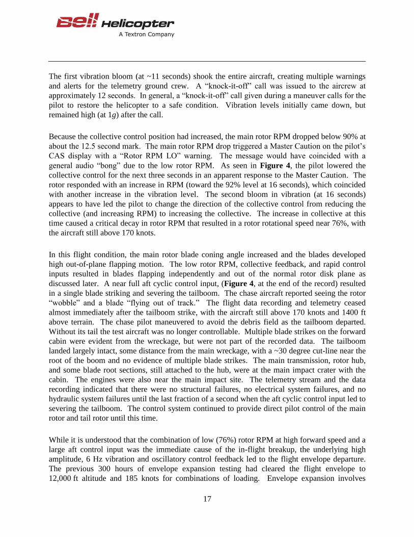
level at about 6.5 seconds. In Figure 6, a 6 Hz band pass filter is applied to the vertical vibration
signal to highlight the predominant 6 Hz frequency of the vibration. In referring to the second
subplot of Figure 4 (labeled “Aircraft-Pilot Collective Coupling), the vertical vibration of the
pilot seat generated an involuntary 6 Hz biomechanical oscillatory motion of the collective
control position that further amplified the vibration level and (with other factors discussed later)
resulted in the first vibratory bloom (labeled “2.5g bloom”) in the lower subplot of Figure 4.
The 2.5g vibration bloom (at 11 seconds and again at ~17 seconds) was nearly 40 times the
normal vibration level seen in the experimental aircraft.
Figure 5. Completed test records 48 and 50, just prior to the accident record (51),
showing rotor RPM recovery to 103% RPM with modulation of collective
control.
Referring to the collective control position in Figure 4, it is seen that the collective (while
undergoing 6 Hz involuntary oscillation) also undergoes an increase in mean position (from 10.5
seconds to 11.5 seconds). It is believed that the mean increase in collective position is related to
the pilot undergoing significantly increased vertical vibration, and the pilot may have been
unaware of the command. Nevertheless, the increased collective position represents an adverse
increased power requirement by the rotor. With only single engine power available, a reduction
in RPM is evident in the main rotor (see the top of Figure 4).
16
Figure 6. Pilot seat vertical vibration with band pass filter showing 6 Hz signal content.
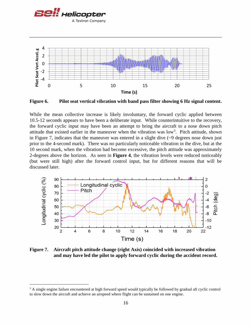
While the mean collective increase is likely involuntary, the forward cyclic applied between
10.5-12 seconds appears to have been a deliberate input. While counterintuitive to the recovery,
the forward cyclic input may have been an attempt to bring the aircraft to a nose down pitch
attitude that existed earlier in the maneuver when the vibration was low3. Pitch attitude, shown
in Figure 7, indicates that the maneuver was entered in a slight dive (~9 degrees nose down just
prior to the 4-second mark). There was no particularly noticeable vibration in the dive, but at the
10 second mark, when the vibration had become excessive, the pitch attitude was approximately
2-degrees above the horizon. As seen in Figure 4, the vibration levels were reduced noticeably
(but were still high) after the forward control input, but for different reasons that will be
discussed later.
Figure 7. Aircraft pitch attitude change (right Axis) coincided with increased vibration
and may have led the pilot to apply forward cyclic during the accident record.
3 A single engine failure encountered at high forward speed would typically be followed by gradual aft cyclic control
to slow down the aircraft and achieve an airspeed where flight can be sustained on one engine.
-4
-2
0
2
4
0 5 10 15 20 25Pilo
t Se
at V
ert
Acc
el,
g
Time (s)
17
The first vibration bloom (at ~11 seconds) shook the entire aircraft, creating multiple warnings
and alerts for the telemetry ground crew. A “knock-it-off” call was issued to the aircrew at
approximately 12 seconds. In general, a “knock-it-off” call given during a maneuver calls for the
pilot to restore the helicopter to a safe condition. Vibration levels initially came down, but
remained high (at 1g) after the call.
Because the collective control position had increased, the main rotor RPM dropped below 90% at
about the 12.5 second mark. The main rotor RPM drop triggered a Master Caution on the pilot’s
CAS display with a “Rotor RPM LO” warning. The message would have coincided with a
general audio “bong” due to the low rotor RPM. As seen in Figure 4, the pilot lowered the
collective control for the next three seconds in an apparent response to the Master Caution. The
rotor responded with an increase in RPM (toward the 92% level at 16 seconds), which coincided
with another increase in the vibration level. The second bloom in vibration (at 16 seconds)
appears to have led the pilot to change the direction of the collective control from reducing the
collective (and increasing RPM) to increasing the collective. The increase in collective at this
time caused a critical decay in rotor RPM that resulted in a rotor rotational speed near 76%, with
the aircraft still above 170 knots.
In this flight condition, the main rotor blade coning angle increased and the blades developed
high out-of-plane flapping motion. The low rotor RPM, collective feedback, and rapid control
inputs resulted in blades flapping independently and out of the normal rotor disk plane as
discussed later. A near full aft cyclic control input, (Figure 4, at the end of the record) resulted
in a single blade striking and severing the tailboom. The chase aircraft reported seeing the rotor
“wobble” and a blade “flying out of track.” The flight data recording and telemetry ceased
almost immediately after the tailboom strike, with the aircraft still above 170 knots and 1400 ft
above terrain. The chase pilot maneuvered to avoid the debris field as the tailboom departed.
Without its tail the test aircraft was no longer controllable. Multiple blade strikes on the forward
cabin were evident from the wreckage, but were not part of the recorded data. The tailboom
landed largely intact, some distance from the main wreckage, with a ~30 degree cut-line near the
root of the boom and no evidence of multiple blade strikes. The main transmission, rotor hub,
and some blade root sections, still attached to the hub, were at the main impact crater with the
cabin. The engines were also near the main impact site. The telemetry stream and the data
recording indicated that there were no structural failures, no electrical system failures, and no
hydraulic system failures until the last fraction of a second when the aft cyclic control input led to
severing the tailboom. The control system continued to provide direct pilot control of the main
rotor and tail rotor until this time.
While it is understood that the combination of low (76%) rotor RPM at high forward speed and a
large aft control input was the immediate cause of the in-flight breakup, the underlying high
amplitude, 6 Hz vibration and oscillatory control feedback led to the flight envelope departure.
The previous 300 hours of envelope expansion testing had cleared the flight envelope to
12,000 ft altitude and 185 knots for combinations of loading. Envelope expansion involves
18
extensive rotor dynamic assessments, where the rotor controls are dynamically stimulated and the
system damping is confirmed. Testing showed that the rotor modes were well damped at 100%
RPM, throughout the flight envelope. Although a period of low rotor RPM can occur for this
type of maneuver, the sustained departure from nominal rotor RPM to 92% RPM while at high
forward speed is a key aspect of the accident. As discussed earlier, the simulated single engine
failure test point is considered complete when (after the power loss) the collective control has
restored the rotor to nominal RPM. Upon power loss, the rotor RPM generally follows a
deceleration/acceleration pattern that is considered transient while the recovery is underway. For
the accident record, the decelerating transient is apparent (and is consistent with the collective
control input), but the accelerating phase never increased the rotor speed above 93%. The
resulting ‘steady state’, low RPM condition, initiated a sequence of events that amplified cabin
vibration by coupling a main rotor dynamic mode with the airframe via control system feedback.
The behavior of the main rotor is governed by various dynamic modes. As a rotor turns, the
blades participate in various patterns of lead-lag motion (modes). The frequency of each mode is
primarily a function of rotor RPM, blade mass/stiffness properties, and lead-lag damper
properties. While the mode frequencies can be predicted, the amplitude of motion is a more
complex phenomenon, driven primarily by a rotor blade’s periodic aerodynamic excitation force.
Mode responses are evaluated in flight testing to show that sufficient damping exists over the
operating envelope. Each rotor mode can be expressed in terms of a rotating reference frame
(attached to the rotor hub), or the airframe fixed (non-rotating) reference frame. The fixed frame
of reference is used below to facilitate a description of the events in the accident record.
Frequencies of the main rotor and tail rotor modes of interest are shown in terms of the non-
rotating (fuselage fixed) reference frame in Figure 8. The airframe first vertical bending mode
frequency is also shown by the dashed horizontal line. Since fixed system rotor mode
frequencies are a function of rotor RPM, the rotor modes have a slope, whereas the airframe
represents a non-rotating structure, unaffected by rotation, and does not change with RPM.
Figure 8 does not assign amplitude to any of the modes and only shows the modal frequencies.
Referring first to the tail rotor, the accident record indicates that the tail rotor cyclic regressing
mode was the predominant tail rotor “blade pattern” as the rotor decelerated to 93% RPM. At
the same time, the main rotor’s cyclic regressing mode (near 2.4 Hz) was the dominant pattern4.
The airframe first vertical bending mode frequency (verified by airframe vibration tests) was near
5.4 Hz.
4 Multiple rotor modes are present at any given time. The dominant mode is determined from measured damper
motion.

19
Figure 8. Airframe, Main Rotor, and Tail Rotor dynamic modes predicted and measured
during the accident record.
Figure 4 showed that after engaging the OEI training mode and arresting the rotor RPM decay,
the rotor rotational speed remained below 93% RPM for the remainder of the record. The
continued low rotational speed of the rotor led to high vibration levels throughout the helicopter.
In the fixed frequency chart (Figure 8), it is seen that at this low RPM, the tail rotor cyclic
regressing mode frequency crosses the 5.4 Hz first vertical bending mode frequency of the
airframe. Of itself, the crossing of frequencies is not an issue since the behavior of the tail rotor
and airframe system is well damped, with vibration levels at the 5.4 Hz frequency quite low (see
Figure 6 prior to 6.5 seconds). At about 6.5 seconds, the dominant main rotor phasing transitions
to the scissors regressing mode. With the scissors mode dominant, all measured frequencies shift
to the ~6 Hz scissors mode frequency. The scissors mode produces fore/aft oscillatory loading of
the mast through aerodynamic forces.

20
The vertical bending mode of the airframe includes fore/aft pitching motion of the main rotor
mast and vertical/lateral motion of the forward cabin. The motions of the airframe are illustrated
in Figure 9, which shows (in highly exaggerated displacement) an overlay of the airframe at its
minimum and maximum displacement for the first vertical bending mode. The forward part of
the cabin (which includes the pilot seat and the attitude heading reference systems) sees mainly 6
Hz up-down vertical motion. In contrast, the response of the main rotor mast to fuselage bending
is primarily fore/aft pitching. With reference to the main rotor tip path plane (not shown), the
mast’s fore/aft pitching motion is equivalent to the application of fore/aft cyclic. At high forward
speed, cyclic control inputs of this nature constitute a stimulus for the main rotor scissors mode.
Figure 9. Illustration of the airframe first vertical bending mode (with highly exaggerated
displacement) shows the forward cabin motion as primarily up and down, while
the main rotor mast pitches fore/aft.
To further describe the progression of the accident record, the pilot seat vertical vibration
amplitude is added to the fixed system frequency chart of Figure 8 in Figure 10. The pilot seat
vertical vibration level is denoted by the scale to the right of the figure, while the timing of the
event is denoted by 1-second interval markers that coincide with the time axis of Figure 4. It is
seen that vibration levels initially remain low, even after the main rotor transitions to the scissors
mode. However, Figure 10 shows that with the main rotor dominated by scissors response, the
character of vibration for the pilot seat begins to respond at the scissors mode frequency.
21
Figure 10. Modal frequencies of the Airframe, Main Rotor, and Tail Rotor with amplitude
of Pilot seat vertical vibration.
Figure 10 shows that the ~6 Hz main rotor scissors mode is the predominant rotor pattern at
approximately 6.5 seconds into the accident record. Pilot seat vibration is low at 6.5 seconds but
the scissors mode feeds a low amplitude ~6 Hz vibration through the airframe bending motions.
Aerodynamics of the scissors mode produces a fore/aft forcing of the main rotor hub at the
scissors mode frequency. Fore/aft motion of the hub, in turn, transfers mast pylon rocking
motion to the airframe resulting in 6 Hz vertical motion at the pilot seat and at the location of the
Attitude Heading Reference System (AHRS) in the forward cabin. Airframe vertical bending
couples with airframe lateral bending and some lateral 6 Hz motion is also produced in the
airframe.
As shown in Figure 10, the 6 Hz pilot seat vibration begins at low amplitude, (beneath the
normal background vibration level). The fore/aft hub forcing, airframe bending, pilot seat
motion and AHRS motion form a closed loop feedback path that amplifies the 6 Hz vibration

22
through biomechanically induced (6 Hz) motion of the collective stick and 6 Hz motion (vertical
and lateral) of the AHRS. The amplification in pilot seat vibration and collective control
oscillations was shown in Figure 4.
The complex nature of scissors mode amplification will not be discussed in detail. For the
accident record, it is understood that the collective command, cyclic stick commands, and AHRS
commands drove the amplification of the cabin vibration. In forward flight, oscillatory control
inputs in these systems stimulate the scissors mode, which, although inertially reactionless,
generates strong aerodynamic forces that are passed into the fixed system as fore/aft forces at the
mast.
The significant out of plane blade motions in the accident record may be understood by
considering the impact of the 6 Hz collective input on the main rotor. A collective control
undergoing 6 Hz cycles, while turning a 4 Hz rotor, produces an anomalous control input.
Collective (as the name implies) is intended to generate a uniform thrust increase on all blades
and generally leads to simultaneous “coning” of the blade pattern in flight. In high speed forward
flight, a high frequency oscillatory collective input (higher than the rotor’s rotational frequency)
will generate blade to blade thrust variations that depend on the timing of the blade’s azimuthal
position with the collective position. For example, if the stroking collective control is at its peak
position when Blade No. 1 is on the advancing side of the rotor disk, then that blade will see a
large lift increase. The very next blade (Blade No. 2) will arrive on the advancing position with
the collective already into the down stroke and that blade see less lift. By the time Blade No. 1
returns to the advancing side (one revolution later), the collective will be at its minimum, and
now Blade No. 1 sees a strong lift reduction (compared to the other blades). In response to the
lift changes, out of plane blade flapping motion occurs. All five blades participate (to varying
degrees) in the azimuthally varying lift arising from forward speed and the 6 Hz collective
motion. Under these conditions, the familiar “rotor tip path plane” becomes blurred, with blades
undergoing independent out of plane motion rather than smoothly tracking one another. The
varying blade aerodynamic forces (due to the 6 Hz collective motion) also appear to further
stimulate the scissors mode response of the main rotor, amplifying the airframe vibration and the
collective biomechanical feedback response.
In addition to pilot biomechanical feedback, the airframe vibration also affected the Attitude
Heading Reference Systems (AHRS) mounted in the forward cabin. In aircraft control systems,
the general principal of using an AHRS is to detect uncommanded accelerations of the aircraft.
For example, if a helicopter is hovering in gusting winds with the cyclic control held fixed, one
might expect the helicopter to drift in response to the buffet forces. The AHRS senses the
helicopter accelerations and makes a determination as to whether the pilot commanded the
motion. Since the pilot’s control did not move, the AHRS signal will be used to automatically
supply appropriate control inputs that neutralize the uncommanded accelerations due to the gust.
Since the AHRS operating bandwidth fell within the 6 Hz vibration frequency, the AHRS was
able to participate in the airframe vibration response. Since the AHRS is mounted in the forward
23
cabin, it sensed the combined “stirring” motion due to the 6 Hz vertical and lateral bending
response of the airframe. In comparison to the sensed stirring motion in the forward cabin, the
pilot cyclic control motions are small. Thus, the AHRS applied control commands to the main
rotor. The 6 Hz stirring of the main rotor swashplate is another source of continued scissors
mode stimulation.
3.1 Control Filtering
The AHRS units communicate with the control system to achieve numerous benefits, particularly
in the arena of handling qualities and reduced pilot workload. Envelope expansion testing is
generally focused on the nominal rotor rotational speed of 100% RPM. In the accident record,
simulated single engine failure testing uncovered the vibratory feedback issue while remaining at
~92% rotor RPM. Although there were no structural or system failures prior to the tailboom
strike, the feedback cycle that led to large amplitude cabin vibration was a root cause of the
accident. The control laws are designed to account for known system modes and handle the
biomechanical feedback scenario through control filtering methods. The control system inputs
(Stick inputs and AHRS) are passed through filters that attenuate frequency content near the
system modes. Setting the filter depth and frequency band involves a careful exercise in
attenuating the undesirable frequency content without negatively impacting the aircraft handling
qualities. For operation at 92% RPM at high forward speed, the filters did not sufficiently
attenuate the 6 Hz control system inputs passed to the main rotor actuators.
For the cyclic control, notch filters were placed near the airframe structural resonance frequencies
to attenuate the ability to pass undesirable excitation frequencies to the rotor swashplate actuators
while permitting low frequency control inputs to pass through and control the aircraft. In the
pilot’s collective axis, no filtering was present in the prototype aircraft at the time of the accident.
In general, filters are added precisely and only as necessary, both to avoid unnecessary
complexity and to avoid negatively impacting the aircraft handling qualities. This approach,
established over many years of development activity at Bell Helicopter had demonstrated no
previous need for a collective filter. Without a filter in the test aircraft, all 6 Hz collective
control motion (except for instances of rate limiting discussed next) was passed to the main rotor
actuator. It is possible that biomechanical feedback could be attenuated by releasing the
collective control or by higher friction settings on the control stick. However, there was no
indication that the pilot attempted to release the control at any time.
There were several instances in the accident record where the pilot collective oscillation was
attenuated by collective rate limiting. At times where the vibration was the highest (11.5 seconds
and 17.5 seconds in Figure 4), the biomechanical collective motion produced collective rates
that exceeded a prescribed limit in the control laws. Figure 11 shows the effect of collective rate
limiting. The green curve represents the rate-limited collective control that was applied to the
main rotor actuators during the accident record. Without rate limiting, the larger cycles of the
blue curve would have been sent to the main rotor actuator. By comparing Figure 11 with Figure
24
4 (Pilot seat vibration), it is seen that when collective rate limiting was in effect, the diverging
vibration blooms reverted to lower vibration levels. The rate limiting appears to damp the
feedback cycle, reducing the vibration level from 2.5g to 1g shortly after 11.5 seconds and again
at 17.5 seconds. It is believed that since the damping of vibration coincided with the forward
cyclic and positive collective at 11.5 seconds, the pilot may have associated the vibration
reduction with those control inputs. This “negative training” may explain the second application
of forward cyclic control and positive collective during the second vibration bloom at 17 seconds
(assuming the pilot was attempting to reduce vibration levels).
Figure 11. Biomechanical feedback of the collective control is inhibited by collective rate
limiting enforced by the control laws. Rate limiting reduced the oscillatory
collective input applied at the main rotor actuators and appeared to dampen
the feedback cycle, reducing pilot seat vibration.
25
4. CONCLUSIONS
While at a high airspeed test point, a sustained low rotor RPM allowed for the development of
high vibration throughout the aircraft. The high vibratory environment led to adverse control
inputs that reduced the rotor RPM to critical levels and resulted in high flapping of the rotor
blades. A near full aft cyclic control input led to one of the rotor blades severing the tail boom
and loss of control of the aircraft.
In the accident record, components of the helicopter interacted as a closed-loop dynamic system.
A main rotor scissors mode transmitted vibrations into the airframe through the rotor mast. The
vibratory forces were transmitted throughout the airframe, including the pilot seat and forward
cabin, at 6 Hz. At the pilot seat, these vibrations were passed to the control sticks through an
unintentional biomechanical response. The vibratory motion in the forward cabin was sensed by
the Attitude Heading Reference System (AHRS), and a corresponding 6 Hz signal was passed to
the flight control system, which responded with a 6 Hz command into the main rotor swashplate.
The 6 Hz biomechanical and AHRS-induced rotor control commands served as unanticipated
excitation amplifiers of the main rotor scissors mode, closing the feedback path on the system.
26
5. GOING FORWARD
As the 525 flight test program continues its development, the design will incorporate a new
collective control filter that targets vibration frequencies near the 6 Hz band. Existing filters in
the cyclic control are tuned and deepened, as are the rate filters in the AHRS system. Enhanced
closed loop system modeling shows that these filter changes would result in a damped response
that attenuates control system feedback and stabilizes cabin vibration throughout the flight
envelope (and outside the flight envelope where the steady 92% RPM led to the amplification of
the main rotor scissors mode). Evaluations of the new filters in the 525 flight simulator indicate
that the impact of the filters is detectable from a handling qualities perspective, but not
objectionable.
Significantly improved analytical capability has been developed for the telemetry monitoring
stations. Going forward, a live-streamed decomposition of all active rotor modes will be
presented on the display monitors. When different rotor modes become simultaneously active
during a test, the flight test team will have immediate assessments of rotor response and specific
modal damping. An incremental test approach is planned for evaluating rotor damping
characteristics at both 100% RPM and reduced steady state RPM. The testing will utilize a new
engine trim file that permits rotor RPM to be adjusted as low as 90% RPM. With this engine
trim file, full engine power will be available at reduced RPM for evaluating rotor damping
without the need for simulated single engine failure scenarios. Simulated single engine failure
testing, throughout the flight envelope, will still be completed separately per existing test plans.
To support future simulated single engine failure testing during the remaining development
testing, the Special OEI Training Mode of the test aircraft will incorporate a “kick-out” that
automatically exits the training mode if the rotor RPM ever drops below 80%. This feature
would restore full (dual) engine power and recover rotor RPM to 100% without pilot
intervention. The 525 Production OEI Training Mode always planned a “kick-out” near 90%
RPM. Both the test aircraft and the 525 production aircraft will also feature a button on the
control stick to facilitate disengaging the OEI training mode.
For improved situational awareness, particularly in a high vibratory environment, a new high
visibility dedicated “Low Rotor RPM” warning light is added to glare shield of the test aircraft
and will become the 525 production standard. Previously the Low RPM warning was part of the
pilot’s primary display.
For the accident record, controls were flown without stick trim forces (pilot pressed the force
trim release buttons on each stick). The reasoning behind the use of “Force Trim Release” in the
cyclic control is as follows: When the aircraft is trimmed at the VH speed, a dive must be initiated
to achieve the VNE speed (a difference of ~20 knots for this test). The test aircraft control system
had a maximum “speed hold” limit near VH and so, any speed over that value required the pilot
27
to hold the higher speed. The pilot could choose to push against the cyclic forces for the entirety
of the test point. Alternatively, the pilot could press the stick force trim release (FTR) button to
remove the forces and eliminate the back drive, permitting more precise targeting of the desired
airspeed.
In the collective axis, the control system applies a tactile cue any time the rotor droops below
103% RPM while on the 30 second engine limit. The collective stick tactile cueing, has two
effects. The tactile cueing increases the friction force by a fixed amount and also attempts to
drive the stick down (so that power available is equal to the 30 second engine limit). Once the
power required is below the engine limit the “additional” friction force is removed and the stick
stops driving down. At the time of the accident, releasing the collective “trim force” had the
effect of removing the “back driving,” but did not remove the additional friction force. Pressing
the collective FTR button, as done in the accident record, permitted more precise control of
power to set the test point initial conditions. The effect of flying the test point with FTR took
away the backdrive cueing that would encourage the pilot to lower the collective to eliminate the
rotor droop. To improve situational awareness in the future, tactile backdrive cueing will remain
active when the FTR button is pressed.