behavior of structures in fire and real design – a case …c.ymcdn.com/sites/ · behavior of...
TRANSCRIPT

Behavior of Structures in Fire andReal Design – A Case Study
S. LAMONT* AND BARBARA LANE
Arup Fire, Ove Arup and Partners13 Fitzroy Street, London, W1T 4BQ
United Kingdom
GRAEME FLINT AND ASIF USMANI
The University of EdinburghThe King’s Buildings, Mayfield RoadEdinburgh, EH9 3JL, United Kingdom
ABSTRACT: A great deal of work on the behavior of composite steel–concretestructures in fire has been developed since the Cardington frame fire tests (UK)conducted in the 1990s. This has now been broadened so that the design of structuresto resist fire has a real engineering basis and is not reliant on results from singleelement testing in the standard furnace.Several projects involving office buildings in the UK and abroad have highlighted
the need for developing the understanding of whole frame behavior in fire. Sincethe collapse of the World Trade Center in New York City in 2001 (9/11), robustengineering solutions incorporating the response of a building to fire are in greatdemand. The basics of structural mechanics at high temperatures can be used in suchdesigns to understand the fire response of many structures with the aid of computermodeling.This article provides a direct comparison between the structural response of an
eleven-story office building in the city of London, when designed in a prescriptivemanner with applied fire protection on all load bearing steelwork, and the responseof the same structure designed using a performance-based approach leavingthe majority of secondary steelwork unprotected. The intent is to demonstrate thatstructural stability during a fire can be maintained in specific cases without relyingon passive fire protection.This study contributes to the field of structural fire engineering by extending
the research work previously conducted by the author to a real design case andaddresses the issues raised by approving authorities, insurers, and the client when afire engineered approach is used to calculate structural response to fire. It alsodemonstrates the use of advanced analysis to understand beam-core connection
*Author to whom correspondence should be addressed. E-mail: [email protected]
Journal of FIRE PROTECTION ENGINEERING, Vol. 16—February 2006 5
1042-3915/06/01 0005–31 $10.00/0 DOI: 10.1177/1042391506054038� 2006 Society of Fire Protection Engineers

response in a fire, as part of a series of global finite element analyses to ensurethat the unprotected structure proposed provides structural stability and maintainscompartmentation for the design fires agreed upon among the necessarystakeholders in this project.
KEYWORDS: fire engineering, design fires, structural response, thermal expansion,performance-based design, prescriptive design, approvals process.
INTRODUCTION
RECENT RESEARCH IN the field of structures in fire has been usedto provide a robust design solution to the passive fire protection
arrangement for an eleven-story office building in London, UK. Detailedfinite element analysis (FEA) allows engineers to examine the structuralbehavior of a composite steel frame as it continues to support loadingduring a fire. In some cases, this type of analysis permits a reduction in thenumber of steel beams that require passive fire protection, while maintainingstructural stability and compartmentation. This form of analysis alsohighlights areas where the structure is less robust during a fire and whereadditional fire protection or structural measures may therefore need to beintroduced. Robust structures at ambient temperatures may not necessarilybe robust when exposed to fire. Especially since 9/11, the owners andoccupiers of tall buildings have demanded that design teams predict theresponse of structures to fire as an essential part of the design and approvalsprocess.
The Cardington frame fire tests [2] in the UK in the 1990s provided awealth of experimental evidence about how whole frame composite steel–concrete structures behave in fire. The Cardington frame continued to carrythe load during a number of full-scale fire tests despite, in most cases, havingno fire protection on any of the steel beams (unprotected steel often reachedtemperatures in excess of 900�C). The columns were generally protectedto their full height. In all tests, there was considerable deflection of thecomposite floor slab in the region of the fire. However, the local and globalstability of the structure was maintained and no breach of compartmenta-tion was observed, floor-to-floor or floor-to-core.
Historically, fire resistance design of structures has been based uponsingle element behavior in the standard fire resistance test [3]. Engineershave always recognized that whole frame structural behavior in fire cannotbe described by a test on a single element because it does not representthe alternative load paths in a full structural frame. However, it is only inrelatively recent years since the Broadgate Phase 8 fire in London, UK [4]and the subsequent Cardington frame fire tests [2] that researchers have fully
6 S. LAMONT ET AL.

investigated and understood the behavior of whole frame composite steel–concrete structures subjected to fire.
The main conclusions from the tests and the subsequent researchprojects [2,5–8] were that composite framed structures possess reserves ofstrength by exhibiting large displacement configurations with catenaryaction in beams and tensile membrane behavior in the slab [5–8] (seeschematic representation in Figure 1). The tensile membrane action in theslab is supported by a compression ring around the boundary of the slaband by anchoring of the reinforcement through the shear studs connectingthe boundary steel beams to the slab. Furthermore, for the duration of theCardington tests, thermal expansion and thermal bowing of the structuralelements, rather than material degradation or gravity loading, governedthe response to fire [5]. Large deflections were not a sign of instability,and local buckling of beams helped thermal strains to move directly intodeflections rather than cause high stress states in the steel. Runawayfailure (a rapid increase in the rate of deflection) was not observed in theCardington tests. However, had failure occurred, researchers believe thatgravity loads and strength would have been the critical factors nearimpending failure [5].
An indeterminate structure, such as a multistory frame, is capable oftransferring load through many alternate load paths. This is true at ambientand high temperatures that occur in fire. Consequently, the pattern of forcesand stresses in an indeterminate beam (as part of a structure) are determinedby the relative stiffness of the other parts of the structure as well asequilibrium considerations. Compatibility of deflections in both directionsor spans of a floor plate will also play a key role. If a structure has adequateductility and stability, the redundancy under fire conditions enablesthe structure to find alternative load paths and mechanisms to continuesupporting additional load when its strength has been exceeded at a singlelocation.
In general, the key aim of the design and detailed analysis presentedhere was to meet the functional requirements of the Approved Document B(fire safety [9]) of the Building Regulations in the UK. In this context,this means that the compartmentation arrangements and passive fireprotection be designed to maintain the stability of the structure for a
δ
(a) 1D Catenary action in beams (δ = deflection) (b) 2D Tensile membrane action in slabs
Figure 1. Catenary action in beams and tensile membrane action in slabs. (The color versionof this figure is available on-line.)
Behavior of Structures in Fire and Real Design – A Case Study 7

reasonable period and limit fire and smoke spread to the floors above thefire floor.
FIRE RESISTANCE TESTING VERSUS
WHOLE FRAME BEHAVIOR
The fire resistance levels recommended in regulatory documents arebased on the behavior of single structural elements heated in a furnace witha standard fire exposure. The fire resistance of the structural elementis taken as the time, to the nearest minute, between commencement ofheating and the time at which failure occurs. Periods of fire resistance arenormally specified as 0.5, 1, 1.5, 2, 3, and 4 h, respectively.
This measurement of fire resistance is known as the standard furnacetest or the fire resistance test [3]. The test determines the ability of abuilding element to continue to perform its function for a period oftime without exceeding defined limits. Specifically, for load bearingelements and/or separating elements of construction in the UK, BS 476Part 20 [3] defines three criteria for insulation, integrity, and stability thatmust be passed in order to achieve a fire resistance rating. For stability ofhorizontal load bearing elements of structure, for example beam and floorslab, failure is defined at a deflection of L/20, or when the deflectionexceeds L/30, failure can be defined as a rate of deflection of L2/9000dwhere, L is the clear span of the specimen under test and d is the distancefrom the top of the structural section to the bottom of the design tensionzone. This limit is based on the size of a typical standard test furnaceand the maximum deflection that can be achieved without causing damageto the furnace. Therefore, in a code compliant building in the UK, withall structural elements protected, a floor may deflect up to L/20. For a7.5-m-long beam, this equates to 375mm and for an 18-m-long beam, thisis 900mm.
Owing to its simplicity, the furnace test does not consider vital structuralphenomena found in the 3D behavior of real buildings including:
. Large deflections.
. Restrained thermal expansion and thermal bowing.
. Membrane and catenary load carrying mechanisms in slabs and beams,respectively.
. Compatibility of deflections in two or more directions in an integratedstructural frame, for example, in a long fire compartment, the long spanwill tend to deflect to a greater extent than the shorter perpendicular spanbecause of the difference in length and the resultant thermal expansion ineach direction.
8 S. LAMONT ET AL.

THE BUILDING
The case study presented here to compare and contrast performance-based design and a ‘code compliant’ structural design for fire, consists of aneleven-story office building, eight storys above the ground and three below,at Mincing Lane in London.
The floor plate measures 40m� 60m (see Figure 2). There is a concretecore at the center of the building containing services and escape stairs,which are also designed for fire fighting. The cores are enclosed in 2-hfire rated construction and provided with dedicated fire fighter lifts,a rising main, and a lobby/vestibule separating the stairs from theaccommodation. The floor slabs are compartment floors of compositesteel and normal weight concrete construction. Composite action isachieved by shear studs between the top flange of the beams and theconcrete dovetail deck slab. Over two-thirds of the floor plate, secondary,and primary steel beams span 9m between the core and the main columnline and then shorter beams (�2.5m long) span between the main columnline and the masonry facade. To the rear of the building, primary andsecondary steel beams span 10m between the core and the column line onthe facade.
Two sides of the building have a load-bearing stonework facade, whichbehaves as columns at 3-m centers. The remaining two sides are steel frameswith cladding.
Model 1 (beams span 9m)
Model 2 (beams span 10m)
Masonry façade
Figure 2. Plan of the office building showing the extent of the global FE models.
Behavior of Structures in Fire and Real Design – A Case Study 9

FAILURE CRITERIA IN COMPOSITE FRAME STRUCTURES
To assess the results provided from a FEA, some means of defining‘failure’ must be established. Currently in the UK, there is no regulatorydefinition of ‘failure’.
The term ‘failure’ is not straightforward to define in the context of thistype of analysis. A compartment fire may lead to large deflections of mainand secondary beams but it is unlikely to cause structural collapse, i.e.,stability requirements can be met. However, large deflections could cause abreech of the separating function of a compartment floor or compartmentwall, for example, the wall of the escape cores.
On this basis, the following aims and assessment methods wereproposed to the stakeholders (client, insurer, fire authority, and buildingauthority):
. Stability of the structure would be maintained throughout the design fire.This was primarily assessed by looking at the rate of deflections duringthe fire. Runaway deflections (a rapid increase in the rate of deflection)were assumed to indicate incipient failure of the floor system and pullingin of the columns.
. Horizontal compartmentation would be maintained for the durationof the design fire. This was also assessed by monitoring the rate ofdeflection of the composite floor. A rapid increase in deflection inany region of the floor plate was assumed to imply compartmentationfailure.
. Vertical compartmentation via the vertical fire fighting shafts would bemaintained for the duration of the design fire. This was assessed bymonitoring the connections at the shaft wall to ensure that theymaintained their capacity for the fire period.
THE GLOBAL FE MODELS
Two finite element (FE) models were developed using commercialsoftware [10] to represent the behavior in a typical floor plate. Two areasof the building were chosen to be modeled as shown in Figure 2. Model 1(Figures 3 and 4) represented the structure spanning onto the masonryfacade and the transition zone where the direction of the slab span changesat the corner of the building. The beams are 9m long on this side of thebuilding. Model 2 (Figures 5 and 6) represented the slightly longer 10m spanbeams at the rear of the building.
The larger, 9m span model 1, is shown in Figures 3 and 4. The pro-posed protection arrangement is shown in Figure 3 in the region modeled.
10 S. LAMONT ET AL.

The primary, edge, and short secondary beams are protected leaving themain secondary beams bare. The columns and the steelwork in the firefighting shaft and the core are fully protected.
The 10m span model 2 represented a structural bay 9m� 10m and isshown in Figures 5 and 6.
The material properties assumed in both FE models are given in Table 1;full degradation of the stress–strain curves with temperature was allowed.Values of thermal expansion for steel and concrete were also taken from the
Figure 3. Proposed protection arrangement.
Columns representedby vertical elementsacting over two floors
Fire below floor slabShell elements representing the slab
Figure 4. The 9 m span global model 1.
Behavior of Structures in Fire and Real Design – A Case Study 11

appropriate Eurocodes (EN 1993-1-2 for steel and EN 1991-1-2 forconcrete).
In accordance with BS 5950 Part 8 [13], during a fire, the partial factors tobe applied to live and dead loads are 0.8 and 1.0, respectively. These factors
Node 110
Unprotected secondary beams
Symmetry boundary conditions
Core wall
Column
Protected edge beams and column
Node 210
Figure 5. Schematic plan view of the 10 m span global model.
Column modeled over two floors
Fire compartment is below the modeled slab
Composite floor slab (deflected shape before and after the fire)
Figure 6. The 10 m span global model 2.
12 S. LAMONT ET AL.
were applied to the characteristic dead and live loads assumed by thestructural engineer for the cold design. The load assumed to act over thefloor slab of a typical office floor in the models was 7.85 kN/m2.
The boundary conditions assumed in the FE models were as follows:
. Columns were fixed at their base and restrained in the horizontaldirections but free to deflect vertically at the top. These boundaryconditions simulated the continuity of the columns at the base of thestructure and at the top of the columns.
. Slab and beams were fully fixed at the core wall.
. Symmetry boundary conditions were applied along the sides of the modelparallel to the secondary beams.
. In the 9m span model (Model 1), the short secondary beams wereassumed to be axially restrained by the masonry facade, but rotationallyfree.
. The 10m span model assumed symmetry boundary conditions onboth sides perpendicular to the core (see Figure 5). These are veryconservative, as it assumes that the floor plate is an infinitely longrectangle, which is significant because research has shown that squarepanels, supported on all four sides by protected composite beams, aremuch stronger than rectangular panels that are effectively supported ontwo sides only and span in one direction. In other words, the squarearrangement allows 2D membrane action whereas the rectangle relies on1D catenary action similar to the load carrying mechanism in beams atlarge deflections.
In both models, four-node shell elements were used to represent the slab.Two-node beam elements were used to represent the beams, columns,and slab ribs. Each element was associated with its appropriate sectionproperties and material characteristics.
The columns were modeled on the fire floor and the floor above (seeFigures 4 and 6). Slab shell elements were not connected to columns becausestress can ‘flow’ around the column as a result of slab continuity and themodels represented this. Slab elements were connected to beam elementsusing constraint equations between the beam and slab representing fullcomposite action.
Table 1. The material models.
Material Grade Model
Lightweight concrete (slab) C30 Eurocode 2 [11]Reinforcing mesh S460 Eurocode 2 [11]Steel (frame) S275 Eurocode 3 [12]
Behavior of Structures in Fire and Real Design – A Case Study 13

In all cases, the model elements were fully geometrically nonlinear andwere also associated with nonlinear material properties.
Structure Temperatures
The design fires were selected as full flashover conditions on one flooronly assuming the sprinkler system had failed.
The amount of ventilation available to an office fire can vary dependingon the amount of glazing that breaks during the fire. Modern tougheneddouble glazing systems may not break as readily as single panes of ordinaryglass. It was therefore proposed that two levels of ventilation would bemodeled, one with a high opening factor resulting in a relatively shortduration fire with high maximum temperatures and one with a loweropening factor resulting in a greater duration but lower maximumtemperatures.
It was agreed with the approving authorities that the following fireswould be used for modeling purposes:
. ‘Short hot’ fully flashed over whole floor fire with a peak temperature of1200�C and a duration of 30min (assuming 100% of the available glazingbreaks).
. ‘Long cool’ fully flashed over whole floor fire with a peak temperature of950�C and a duration of 145min (assuming 25% of the available glazingbreaks).
. Standard fire of 90min.
The fires are illustrated in Figure 7. It can be seen that the two levelsof ventilation gave two very different fires – one long relatively cool fire,one short relatively hot fire.
The steel temperatures as a result of the fire scenarios were calculatedusing the lumped mass heat transfer equations [12] in Eurocode 3, Part 1.2.These relatively simple equations can be solved using a spreadsheet andallow average temperatures of the steel section to be calculated. The steeltemperatures are illustrated in Figures 8–10 for each design fire. A 1D FEheat transfer model was used to establish the gradient through the depth ofthe slab in response to each design fire.
The slab temperatures in response to the standard fire exposure wererepresented in the structural model by an equivalent mean temperature andassociated linear gradient acting at the centroid of the slab. The equivalentheating regime was calculated by establishing the stress state of the slab inresponse to the actual heating regime and then applying an equivalent stressstate in the form of a mean temperature and linear gradient. This concept isexplained in more detail by Usmani [8] and hence not repeated here.
14 S. LAMONT ET AL.

The slab temperatures in structural models with the ‘design’ fire exposuresincluding cooling were modeled explicitly. The actual temperaturegradients through the depth of the slab were modeled and are illustratedin Figures 11 and 12. The temperature of the slab during the cooling phaseof the ‘design’ fires cannot be represented by the mean temperature andlinear gradient approach used for the standard fire case.
0.0
200.0
400.0
600.0
800.0
1000.0
1200.0
1400.0
0 20 40 60 80 100 120 140 160
Time (min)
Tem
per
atu
re (
°C)
Long cool fire
Short hot fire
Standard fire
Figure 7. Design fires for the structural analysis.
0
200
400
600
800
1000
1200
0 1000 2000 3000 4000 5000 6000
Time (s)
Tem
per
atu
re (
°C)
Standard fire curveProt primary beamProt short secondary beamProt columnProt secondary beamUnp secondary beam
Figure 8. Steel temperatures used in the FE model with standard fire exposure(prot¼protected, unp¼ unprotected).
Behavior of Structures in Fire and Real Design – A Case Study 15

For each structural analysis, it was assumed that there was no gradientthrough the depth or along the length of the steel beams because incomposite frames the most important gradient is that between the slab andthe protected or unprotected steel beams. The gradient over the depth ofthe beam is much less important because it is very small in comparison. Thecolumns on the fire floor were also uniformly heated in the models because
0
200
400
600
800
1000
1200
1400
0 500 1000 1500 2000 2500
Time (s)
Tem
per
atu
re (
°C)
100% Aw 820MJ/m2 atmosphere temperature
Unp secondary beam
Prot primary beam
Prot short secondary beam
Prot secondary beam
Prot column
Figure 10. Temperature histories in the steelwork for the design fire with 100% of theavailable glazing on one floor having failed providing ventilation (prot¼protected,unp¼unprotected).
−200
0
200
400
600
800
1000
1200
0 2000 4000 6000 8000 10000 12000 14000
Time (s)
Tem
per
atu
re (
°C)
25% Aw 820MJ/m2 atmosphere temperature
Unp secondary beam
Prot primary beam
Prot short secondary beam
Prot secondary beam
Prot column
Figure 9. Temperature histories in the steelwork for the design fire with 25% of theavailable glazing on one floor having failed providing ventilation (prot¼protected,unp¼unprotected).
16 S. LAMONT ET AL.

they would be exposed to heating on all four sides during a flashover fire.The slab was assumed to be at a uniform, through depth gradient over thewhole compartment as a result of the whole compartment having flashedover.
00
100
200
300
400
500
600
Tem
pera
ture
(°C
)
700
800
900
1000 2000 3000 4000 5000
Time (s)6000 7000 8000 9000 10000
Slab top3/4 height of slab1/2 height of slab1/4 height of slab
Rib top/Slab bottomRib bottom
Figure 11. Temperature histories in the concrete slab for the design fire with 25% of theavailable glazing on one floor having failed providing ventilation.
00
100
200
300
400
500
Tem
pera
ture
(°C
)
600
700
800
900
1000
2000 4000 6000 8000
Time (s)10000 12000 14000 16000 18000
Slab top3/4 height of slab1/2 height of slab1/4 height of slab
Rib top/Slab bottomRib bottom
Figure 12. Temperature histories in the concrete slab for the design fire with 100% of theavailable glazing on one floor having failed providing ventilation.
Behavior of Structures in Fire and Real Design – A Case Study 17

RESULTS WITH GLOBAL MODEL 1 AND 9m SPANS
Proposed Structure with Unprotected Secondary Steel Beams
in Response to the Standard Fire
A contour plot of the deflection at the end of heating is shown in Figure 13for the case where the slab and beams were axially restrained by themasonry wall. The greatest downward displacement is near the midspan ofthe unprotected secondary beams as expected. The position of the columnsis clearly visible. The structure is very stiff at the corner of the buildingwhere the short, protected secondary beams make a stiff, closely spacedgrid. There is very little displacement in this region.
The midspan displacement of a typical unprotected secondary beamis shown in Figure 14. It is plotted against unprotected secondary beamtemperature. The rate of deflection is very linear, similar to deflection plotsfrom the Cardington tests. Runaway failure (a rapid increase in the rate ofdeflection) is not observed.
The axial force at midspan of a typical secondary beam is shown inFigure 15. As a result of the live load, the beam is in tension initially. Thenthe unprotected steel expands against the surrounding structure producingcompressive forces very rapidly until 140�C when the steel reaches its firstyield. Beyond this temperature, the axial force declines in compressionwith an increasing loss in material strength and stiffness until at the end ofheating, the axial force is effectively zero. At this stage, the slab is thereforecarrying load in membrane action.
The total strains (thermal þ mechanical) in the slab at reinforcement levelare plotted in Figure 16 for the Y- (¼2) direction. Compressions have
490mm
Figure 13. Contour plot of deflection at the end of heating.
18 S. LAMONT ET AL.

negative values and tensions positive values. In general, the slab is incompression or low tension.
Thermal strains will account for about 0.1–0.3% of the total strain values.There are regions of relatively high tension (2–3%) near the core asexpected. These are mainly as a result of the hogging moment at this
0−4.50e+02
−4.00e+02
−3.50e+02
−3.00e+02
−2.50e+02
Dis
plac
emen
t (m
m)
−2.00e+02
−1.50e+02
−1.00e+02
−5.00e+01
0.00e+00
100 200 300 400 500
Temperature (°C)600 700 800
Secondary node 4010
900 1000
Figure 14. Midspan deflection of a typical unprotected secondary beam (secondary node4010¼node number at midspan of the secondary beam in the model).
Axi
al fo
rce
(N)
−1.40e+060 100 200 300 400 500 600 700 800 900 1000
−1.20e+06
−1.00e+06
−8.00e+05
−6.00e+05
−4.00e+05
−2.00e+05
0.00e+00
2.00e+05
4.00e+05
Temperature (°C)
Secondary element 4010
Figure 15. Axial force at midspan of the unprotected secondary beam.
Behavior of Structures in Fire and Real Design – A Case Study 19

boundary. Any localized concrete cracking in this region would relievehogging moments although strains will still be present after cracking as thedeflecting slab pulls on the supports. The ability of the core connection tocope with the conditions during a fire was tested by a detailed connectionmodel briefly described later in this article.
Fully Protected Structure in Response to the Standard Fire
During the design process, a direct comparison was made between thestructural behavior observed in the model of the proposed design (reportedin the previous section) with that which would normally be designed as aresult of the recommendations in the Building Regulations i.e., all structuralsteel protected.
Figure 17 is a contour plot of deflections at the end of heating whenall structural steel is protected. The maximum deflection experienced is390mm. Most secondary steel beams deflect up to 200mm. This is contraryto the common belief that a protected structure does not deflect. Note alsothat this deflection is in excess of the BS476 requirement for L/30 deflec-tion limits for beams/floors. This can be compared to the design case withunprotected secondary beams where the maximum deflection is 490mm andthe midspan deflection of the unprotected secondary beams is about 450mm(see Figures 13 and 14).
Therefore in terms of damage to the structure in the context of insurance,the traditional design approach and the proposed design result in identical
C
T
T
C
≈2%
≈0.1%
Figure 16. Strain in the Y- (¼2) direction at the level of the reinforcement in the slab after90 min of the standard fire exposure. C¼compression, T¼ tension.
20 S. LAMONT ET AL.

structural member replacement measures after a fire of severity assumed inthis model.
The heating regime in this standard fire analysis is based on theassumption that the protected steel will reach a maximum temperature ofabout 550�C at the end of 90min. This is based on the UK requirements forfire proofing.
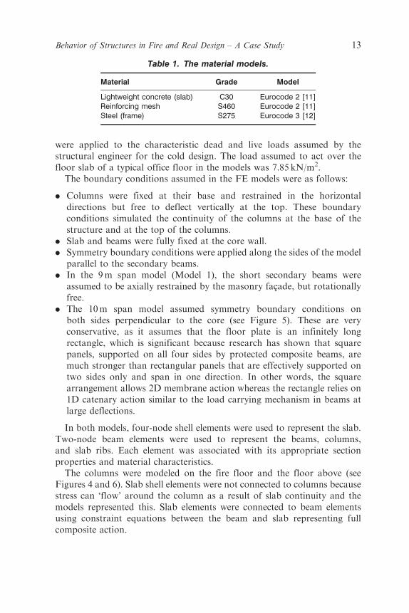
The deflection at midspan of a typical fully protected secondary beam isvery linear i.e., the rate of deflection is not changing (see Figure 18). Thesame behavior was shown in Figure 14 when the beams were unprotectedalthough the deflections were much greater. This suggests the structureis very stable. The uniform rate of deflection was also observed in themeasurements made at Cardington during the fire tests.
The strains in the Y(¼2)-direction are shown in Figure 19. Tensile strainsalong the core edge are in the region of 2%. The greatest tensile strains arearound the column locations and at the core wall. The strains experienced inthe slab when all beams are protected are very similar to the design case withsecondary beams unprotected. It could be expected therefore that the slabwould also experience local cracking in the fully protected case.
Significance of Results from Global Model 1 in Response
to the Standard Fire with 9m Spans
The comparative analyses have shown that the deflection and strainpatterns in the composite slab are very similar for both protectionarrangements. Therefore, it could be assumed that the damage to thestructure would be similar in both cases. The midspan deflection of the floor
390 mm
Figure 17. Contour plot of deflection at the end of heating.
Behavior of Structures in Fire and Real Design – A Case Study 21
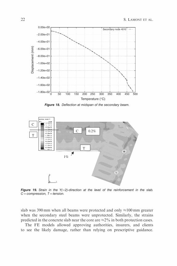
slab was 390mm when all beams were protected and only �100mm greaterwhen the secondary steel beams were unprotected. Similarly, the strainspredicted in the concrete slab near the core are�2% in both protection cases.
The FE models allowed approving authorities, insurers, and clientsto see the likely damage, rather than relying on prescriptive guidance.
C
T
1%
0.2%C
T
Figure 19. Strain in the Y(¼2)-direction at the level of the reinforcement in the slab.C¼compression, T¼ tension.
Dis
plac
emen
t (m
m)
0 50 100 150 200 250 300 350 400 450 500−1.80e+02
−1.60e+02
−1.40e+02
−1.20e+02
−1.00e+02
−8.00e+01
−6.00e+01
−4.00e+01
−2.00e+01
0.00e+00
Temperature (°C)
Secondary node 4010
Figure 18. Deflection at midspan of the secondary beam.
22 S. LAMONT ET AL.

When quoting insurance premiums, insurers have traditionally had to guessthe likely damage to structures in fully flashed over compartment firesbecause real structural behavior is vastly different from the standard furnacetest. The modeling methodology provides invaluable information for allconcerned.
It should be noted that the results of these models is for this particularbuilding and in another structure with different spans and layout, the resultsof a similar comparative study may not be so similar. This type of designprocess must be carried out on a case-by-case basis. Generalized conclusionscannot be made.
RESULTS WITH MODEL 2 AND 10m SPANS
Model 1 captured the most novel part of the building structure, includingthe masonry facade and the slab spanning in two different directions.However, the spans in this region are 9m, whereas on the opposite side ofthe floor plate at the rear of the building, beams span 10m. These larger spansgenerated greater thermal expansion and therefore greater midspan deflec-tions. Larger tensions were observed at the slab to core interface and runawayfailure was observed. This section therefore discusses the differing response ofthe frame at the rear of the building to the two parametric design fires and thedesign changes made to mitigate failure as a result of the observed results.
‘Short Hot’ Fire
Figure 20 shows the deflection at midspan (Node 210, see Figure 5) of thecentral secondary beam against unprotected secondary beam temperatureduring the ‘short hot’ fire. The deflection history is linear in the early stagesof the fire but the rate increases as the temperature increases. At the end ofheating (secondary beam temperature of 1150�C) and into the cooling phaseof the fire, the deflection continues to increase because the slab is stillundergoing heating due to the thermal lag concrete experiences whenexposed to high temperatures. After 800�C, the deflection rate is constantand, if the analysis had been allowed to continue, the deflection wouldpartially recover. As the steel beam experienced considerable yielding inheating, it cannot return fully to its original position.
Figure 21 shows the axial force at midspan of the central secondary beam(Node 210). As expected, the beam is in significant compression as itexpands against its supports during heating. The steel beam yields at atemperature of about 150�C. Beyond this, the beam attracts no morecompression and begins to reduce in compression as the material strength
Behavior of Structures in Fire and Real Design – A Case Study 23

0.00e+00
−2.00e+02
−4.00e+02
−6.00e+02
−8.00e+02
Dis
plac
emen
t (m
m)
−1.00e+03
−1.20e+03
−1.40e+030 200 400 600
Temperature (°C)
800 1000 1200
Secondary node 210
Figure 20. Deflection at midspan of the secondary beam at the center of the model.
6.00e+05
4.00e+05
Secondary element 210
2.00e+05
0.00e+00
−2.00e+05
−4.00e+05
−6.00e+05
−8.00e+05
−1.00e+060 200 400 600
Temperature (°C)
Axi
al fo
rce
(N)
800 1000 1200
Figure 21. Axial force at midspan of the secondary beam.
24 S. LAMONT ET AL.

decreases with increasing temperature. The ultimate yield of the steel beamtakes place at about 500�C.
Between 800 and 1100�C, the beam is in tension, showing that the beam iscarrying load in catenary action. This is a sign of impending runaway failurebecause the structure has to utilize almost all of its strength. Therefore,failure is assumed to occur for this design case.
During the cooling phase of the fire, the steel begins to recover some of itsstrength and moves into tension as the slab (which is still undergoing heatingas a result of thermal lag) pushes the steel beam downward and the steel triesto contract into its original position.
A plot of strain at the level of the reinforcement in the slab in theY-direction is shown in Figure 22 at the end of heating. The greatest totalstrains are at the core edge and around the column (the regions of greatesthogging). Strains at the core were predicted to be about 2% while strainsat the column were about 4%. This is high and, although the concrete willcrack and the mesh is quite ductile, this was not deemed acceptable fordesign. The unacceptable result was addressed by protecting the secondarybeams between the columns to reduce deflections and the analysis repeated.Note that the structural model was conservative because the slab wasassumed to be infinitely long; in reality it is connected to the rest of the floorplate.
4%
2.0%T
T
Figure 22. Strain in the Y-direction at the level of the reinforcement in the slab at the end ofheating.
Behavior of Structures in Fire and Real Design – A Case Study 25

‘Short Hot’ Fire with Secondary Beams Protected between Columns
The deflection at midspan of an unprotected secondary beam is shown inFigure 23 for the ‘short hot’ fire when secondary beams between columnswere protected. The deflection rate is very uniform and the structurebehaves well. Deflections are reduced by about 50% compared to the casewith all secondary beams unprotected (see Figure 20). The total strains inthe Y(¼2)-direction are plotted in Figure 24. The tensile strain at thecore wall is now<1%, compared to 4% when the secondary beams betweencolumns were unprotected. The strains are also lower close to the core wall.
Therefore, by protecting steel beams connected directly to columns,failure is no longer observed to occur, even with all other secondary steelbeams unprotected.
‘Long Cool’ Fire
Midspan deflection of the unprotected secondary beam is shown inFigure 25 with all secondary beams unprotected. The deflection rateincreases rapidly after temperatures of 600�C. Runaway failure wasobserved and the analysis failed to converge as a result of this at 780�C.
This result is not totally realistic because the symmetry boundaryconditions in the model assume an infinitely long slab. If the whole floor
0.00e+00Secondary node 110
−1.00e+02
−2.00e+02
−3.00e+02
Dis
plac
emen
t (m
m)
−5.00e+02
−6.00e+020 200 400 600
Temperature (°C)
800 1000 1200
−4.00e+02
Figure 23. Deflection at the midspan of the secondary beam.
26 S. LAMONT ET AL.

0.00e+00
−1.00e+02
−2.00e+02
−3.00e+02
−4.00e+02
−5.00e+02
−6.00e+02
−7.00e+02
−8.00e+020 100 200 300 400
Temperature (°C)
Secondary node 210
500 600 700 800
Dis
plac
emen
t (m
m)
Figure 25. Runaway deflections of the secondary beam midway through the heating phaseof the fire.
<1%
2.0%T
C
C
T
Figure 24. Strain in the Y-direction at the level of the reinforcement in the slab at the end ofheating.
Behavior of Structures in Fire and Real Design – A Case Study 27

slab had been modeled, the failure is unlikely to have been observed.However, as the conservative FE model did show failure for the ‘long cool’design fire, the secondary beams between columns were protected and theanalysis was repeated.
‘Long Cool’ Fire with Secondary Beams Protected between Columns
The midspan deflections of the protected and unprotected secondarybeams in the revised model are shown in Figure 26. When the secondarybeams between columns are protected, there is no evidence of runawayfailure. Almost all deflections are associated with thermal effects. At anunprotected steel temperature of 800�C, the protected steel beam wouldhave reached about 150�C and buckled near the support, allowing thermalexpansions to be absorbed in downward deflections. This also increases therate of deflection in the unprotected secondary beams.
The strains at the level of the reinforcement are shown in Figure 27 at theend of heating in the Y(¼2)-direction. Maximum total tensile strains ofabout 4% occur in regions along the core edge. Again this is high and ispartly due to the fully fixed boundary condition assumed at the boundary ofthe global model. A local model of the core connection was built to checkthe forces induced in the rebar and to ensure that failure did not occur.
-1.00E+03
-9.00E+02
-8.00E+02
-7.00E+02
-6.00E+02
-5.00E+02
-4.00E+02
-3.00E+02
-2.00E+02
-1.00E+02
0.00E+00
0 100 200 300 400 500 600 700 800 900 1000
Temperature (°C)
Dis
pla
cem
ent
(mm
)
Secondary node 110-unprotected beam
Secondary node 210-protected beam
Figure 26. Midspan deflection of a protected and unprotected beam in the ‘long cool’ fire(see Figure 5 for the location of nodes 110 and 210). (The color version of this figure isavailable on-line.)
28 S. LAMONT ET AL.

Significance of Results from Global Model 2 with 10m Span
The ‘long cool’ fire is worse for this particular structure than the ‘shorthot’ fire. When all the secondary steel beams were left unprotected, runawayfailure was observed for the ‘long cool’ fire only.
Model 2 was conservative as a result of the symmetry boundaryconditions assumed because the real structure is not infinitely longperpendicular to the secondary beams. The aspect ratio of the floor plateis much smaller in reality.
As a result of the structural behavior seen in the 10m span model(Model 2), secondary steel beams between columns were protected to allowtensile membrane action at high temperatures and large deflections todevelop in a 2D manner rather than in a 1D catenary action.
Strains in the rebar at the core to slab interface were found to be high as aresult of the boundary conditions assumed in the global model. In order toensure that the tensile membrane action can be supported without pullingout the connections to the core or rupturing the rebar, an explicit connectionmodel was developed.
<1%
4.0%T
T
C
T
Figure 27. Strain in the Y-direction at the level of the reinforcement in the slab at the end ofheating.
Behavior of Structures in Fire and Real Design – A Case Study 29

CONNECTION MODELING AT THE FLOOR
TO THE CORE BOUNDARY
The global FE modeling of the composite floor slab showed that anumber of secondary steel beams could be left unprotected as they are notessential to the stability of the floor slab during a fire. However, the globalFE model used had a number of simplifications:
. It did not consider concrete cracking explicitly.
. It treated the reinforcement mesh as a smeared layer in the thickness ofthe shell elements representing the slab. This smeared mesh did not modellocalized fracture of the reinforcement.
. It assumed connections are perfect pins or fixed supports with no accountof material degradation.
The global FE analysis appeared to indicate that high loads/deformationswere generated in the beam connections and reinforcement around the core.As the global analysis did not consider the connection details into the coreaccurately, a local explicit model was developed to investigate whether thereinforcement between the slab and the core and the steel beam to coreconnection would be able to remain intact (i.e., not rupture) if some of thesecondary beams were unprotected. The local model included the worst caseof credible design fire defined by the global FE analysis as the ‘long cool’fire.
Connection Model Description
The local model represented a 10m span section of an office floor betweencolumns. The use of symmetry conditions in the model allowed the extentof the model to be limited to a 5m� 4.5m area. The model is shown inFigures 28 and 29. This connection was chosen because it was the con-nection under greatest load from the results of the global models.
In the local model, the back of the core wall was modeled as rigid andfixed. The 10m 305UC97 steel beams were modeled with nonlinear shellelements. The protected primary beam was given fixed ends, whereasthe unprotected secondary beam had a bolted connection detail with thecore wall.
The floor slab was modeled as 130mm thick with a reinforcement grid ofT6 bars at 200mm spacing (0.22% reinforcement). T10 bend-out bars at300mm spacing connect the core wall to the slab. These were represented inthe model by small beam elements, which allowed the connection to fail.
The connection detail for the 10m unprotected beam consists of a platecast into the core wall with a fin plate and 3 M20 Grade 8.8 bolts connecting
30 S. LAMONT ET AL.

Cast-in plate
Fin plate
M20 bolts
Figure 29. The connection detail in the LS DYNA model.
Core wall
Floor slab
4.5m
5m
Symmetry plane
Symmetry plane
Symmetry plane
Unprotectedsecondary steel beam
Protected steelbeam
Figure 28. The LS DYNA model.
Behavior of Structures in Fire and Real Design – A Case Study 31

the fin plate to the web of the beam. The bolts are situated within22� 122mm long slotted holes in the fin plate. In the model, the bolts wererepresented by small rigid patches on the fin plate and web, which wereconnected by small beam elements. All of the characteristics associated withbolt deformation and failure, movement in the slotted holes, and bearingfailure were represented in the properties given to the small beam elements.
The analysis was carried out twice, once with bare steel connections andonce with protected connections. The extent to which the fire protectionwas modeled included the cast-in plate, the fin plate, and the final 225mmof the secondary beam flange and web. All of the material properties andtemperature–time histories were the same as those in the global models forthe ‘long cool’ fire. The connection temperature was assumed to equal theprotected secondary beam temperature.
Connection Analysis Results – Unprotected Connections
The connection model showed that as the steel beams and concrete floorslab started to expand, the floor slab bowed downward and the unprotectedsteel beam rotated downward at the connection detail as the bolts slid withinthe slotted holes. At an unprotected steel temperature of about 370�C,the bottom flange of the beam made contact with the core wall.
The web around the bolts was shown to fail at an unprotected steeltemperature of about 700�C, as shown in Figure 30. At about the same time,a buckle began to appear in the bottom flange of the protected primary steelbeam near to the fixed end. This buckle continued to grow, reaching its peakat a protected steel temperature of about 550�C.
Over the duration of the event, the concrete floor slab developed somecracking, as shown in the plot of maximum principal strain (i.e., tensilestrain) in Figure 31. This shows the regions of greatest tensile strains.
Between unprotected steel temperatures of 800 and 930�C, a couple ofthe T10 bend-out bars around the unprotected secondary steel beam werepredicted to fracture (due to excessive tensile strain). In addition, over theduration of the fire event, many of the other T10 bend-out bars betweenthe unprotected secondary steel beams came close to fracture.
Since the web of the unprotected secondary steel beam failed at theconnection, this steel beam was unable to support the floor slab afterthe fire. Therefore, the floor slab was required to span between the twoprotected secondary beams and/or between the core wall and the oppositeprotected edge beam. This was considered to be an acceptable level ofdeformation in the cooling phase of the fire.
The cracking predicted in areas of the concrete floor slab was relativelyminor and in these areas the reinforcement grid would be expected to
32 S. LAMONT ET AL.

Figure 30. Web fracture around the bolts.
Figure 31. Principal strains.
Behavior of Structures in Fire and Real Design – A Case Study 33

maintain the structural integrity of the floor slab. In areas where the tensilestrain was significant, the reinforcement grid could be expected to fail.The only areas with significant tensile strain in the floor slab were next tothe core wall, between the two unprotected secondary beams. Therefore,it was assumed that the concrete floor slab would not retain a structuralconnection with the core wall in the region between the unprotectedsecondary beams.
However, the rest of the floor slab was predicted to maintain its structuralintegrity (with its reinforcement grid) and was able to span between thetwo primary beams and between the core wall and the opposite primarybeam.
The analysis was repeated with protected connections. The fire protectionsignificantly reduced the damage to the secondary beam and connection,such that they could be assumed to retain their structural integrity. Therewas also a corresponding reduction in the cracking of the concrete floor slaband the failure of the T10 reinforcement bars. The analysis indicated thatonly one T10 reinforcement bar (directly over the secondary beam) mightfracture. Therefore, the connections to the core were protected on site.
CONCLUSIONS
This article provides a snapshot of information and analysis todemonstrate that the passive fire protection arrangement for an officebuilding in London satisfies the appropriate functional requirements ofthe Approved Document B of the Building Regulations, UK. It comparesthe performance of a prescriptively designed structural frame with theperformance of a structural frame having reduced passive fire protection inresponse to credible design fires, all as part of a research approach used tosatisfy the stakeholders of a structural fire engineering solution.
A detailed FEA of the structure with a standard fire and credible designfires was carried out to determine the deflections and forces in the structuralelements.
A direct comparison was made between the structural behavior for aproposed design with secondary steel left unprotected and structuralbehavior with all steel fire protected, as would be the case in a traditionalprescriptive design. The results for the fully protected design were similar tothose for the proposed design and clearly showed that any fire protection onthe secondary beams was redundant.
The comparative analyses have shown that the deflection and strainpatterns in the composite slab are very similar for both protectionarrangements. Therefore, it could be assumed that the damage to thestructure would be similar in both cases.
34 S. LAMONT ET AL.

The comparative study was invaluable in the approvals process becausethe fire brigade, insurers, and approving authorities could quantify thedifferences in response between the prescriptive design they would normallyapprove and the performance of the proposed design with some bare steel.
A conservative model of the 10m span bays in the structure showed thatfailure could occur in this case if all secondary steel beams were unprotected.This is due to the span length, reliance on 1-way catenary action instead of2-way membrane action and the conservative model used. Detailed analysisof both global and local models resulted in a design solution that reliedon the development of tensile membrane action in square panels betweenprotected beams. Therefore, it was proposed to protect specific beams –those spanning directly between columns and connections into the concretecore.
This type of design should be carried out on a case-by-case basis andresults in this article are applicable to this building design only.
REFERENCES
1. Lamont, S., ‘‘The Behaviour of Multi-Storey Composite Steel Framed Structures inResponse to Compartment Fires,’’ PhD Thesis, The University of Edinburgh, 2002.
2. Kirby, B.R., ‘‘Data on the Cardington Fire Tests,’’ Technical Report, British Steel, 2000.
3. ‘‘Fire Tests on Building Materials and Structures,’’ BS 476: Part 20: 1987, BSI BritishStandards, London, 1987.
4. ‘‘Structural Fire Engineering Investigation of Broadgate Phase 8 Fire,’’ Technical Report,The Steel Construction Institute, June 1991.
5. ‘‘Final Report of the DETR-PIT Project: Behaviour of Steel Framed Structures under FireConditions,’’ Technical Report, The University of Edinburgh, 2000 (see www.civ.ed.ac.uk/research/fire/project/main.html).
6. Bailey, C.G. and Moore, D.B., ‘‘The Behaviour of Full-Scale Steel Framed BuildingsSubject to Compartment Fires,’’ The Structural Engineer, Vol. 77, No. 8, 1999, pp. 15–21.
7. Huang, Z., Burgess, I.W. and Plank, R.J., ‘‘Non-linear Modelling of Three Full ScaleStructural Fire Tests,’’ In: Structures in Fire: Proceedings of the First InternationalWorkshop, Copenhagen, June 2000.
8. Usmani, A.S., ‘‘Application of Fundamental Structural Mechanics Principles in Assessingthe Cardington Fire Tests,’’ In: Structures in Fire: Proceedings of the First InternationalWorkshop, Copenhagen, June 2000.
9. Office of the Deputy Prime Minister (ODPM), Fire Safety to Approved Document B,Building Regulations, UK, 2000.
10. ABAQUS, Inc., Rising Sun Mills, 166 Valley Street, Providence, RI 02909-2499, USA.
11. ‘‘Design of Concrete Structures Part 1.2: General Rules-Structural Fire Design,’’ Eurocode2, DD ENV 1992-1-2:2001, BSI British Standards, London, 2001.
12. ‘‘Design of Steel Structures Part 1.2: Fire Resistance,’’ Eurocode 3 DD ENV 1993-1-2:2001,BSI British Standards, London, 2001.
13. ‘‘Code of Practice for Fire Resistant Design,’’ BS 5950:Part 8:1990, BSI British Standards,London, 1990.
Behavior of Structures in Fire and Real Design – A Case Study 35