behavior of single pile in unsaturated clayey...
TRANSCRIPT

Eng. & Tech. Journal , Vol.32,Part (A), No.3, 2014
763
Behavior of Single Pile in Unsaturated Clayey Soils
Dr. Mohammed Y. Fattah Building and Construction Engineering Department, University of Technology/ Baghdad Dr. Nahla M. Salim Building and Construction Engineering Department, University of Technology/Baghdad Isra'a Mohammed Mohsin
Building and Construction Engineering Department, University of Technology/Baghdad Email:[email protected]
Received on: 12/3/2013 & Accepted on: 5/9/2013
ABSTRACT The mechanical behavior of partially saturated soils can be different from that of
fully saturated soils. It has been found that for such soils, changes in suction do not have the same effect as changes in the applied stresses, and consequently the effective stress principles is not applicable.
A finite element analysis was carried out on a single pile with a diameter (0.6 m) and (12) m length embedded in fully and partially saturated clayey Iraqi soils within Baghdad city. The partially saturated parameters were calculated using laboratory methods; the filter paper method was utilized to estimate the soil water characteristic curve (SWCC) from which the H-Modulus function was obtained. The program (SoilVision) was used to make a fit of the SWCC. The finite element programs SIGMA/W and SEEP/W are then used in the analysis. A parametric study is carried out and different parameters are changed to study their effects on the behavior of partially saturated clay. These parameters include the degree of saturation, depth of water table and shear strength of clay. The study reveals that when the soil becomes partially saturated by dropping water table at different depths with different degrees of saturation, the pile capacity increases. It is concluded that the change in the water table level and the degree of saturation has a great effect on the behavior of partially saturated clay. In this work, it is found that due to dropping of water table and contribution of matric suction (i.e. negative pore water pressure), the pile capacity in partially saturated soil is approximately (3-5) times higher than the capacity of piles in the same soil under saturated conditions.
Keywords: Partially Saturated Soil, SWCC, Soil Suction, Pile Capacity, Clay.

Eng. & Tech. Journal , Vol.32,Part (A), No.3, 2014 Behavior of Single Pile in Unsaturated Clayey Soils
764
الطینیة غیر المشبعة تصرف ركیزة مفردة في الترب
لخالصةا التصرف المیكانیكي للترب غیر المشبعة یختلف بدرجة كبیرة عن تصرفھا في الحالة المشبعة وقد وجد أن التغییر في تصرف التربة نتیجة التغیر في ضغط الماء السالب للتربة لھ تأثیر مختلف عن
االجھاد الفعال غیر قابل للتطبیق في الترب غیر التغییر الناتج عن تسلیط االجھادات وبالتالي فأن مبدأ ) م 12( و طول) م 0.6(استخدمت مبادئ میكانیك التربة غیر المشبعة في تحلیل ركائز بقطر . المشبعة
اعتبرت مشبعة مرة وغیر مشبعة مرة أخرى اثناء التحلیل , في ترب أخذت نماذجھا من مدینة بغداد ن خصاص التربة والدوال المتعلقة بالحالة غیر المشبعة تم قیاسھا حیث أ, بطریقة العناصر المحددة
من منحني خصائص الرطوبة الذي تم الحصول علیھ (H)مختبریا وذلك للحصول على المعاملثم , بعد تحدید الخصائص الرئیسیة للتربة (Soil Vision)ومن خالل برنامج .بطریقة ورقة الترشیح
رطوبة الى عالقة نسبة الفجوات وضغط الماء السالب وبعد تعیین تحویل عالقة منحني خصائص الاستخدم في التحلیل . (H-Modulus) استخدمت قیمة المیل لھذه المماسات في أیجاد, مماسات العالقة
حیث تم استخدام عناصر رباعیة بثماني عقد )SEEP/W(و ) (SIGMA/Wبرنامج العناصر المحددة المسام وقد تم تغییر عدة معامالت لدراسة تأثیرھا على سلوك التربة غیر لتمثیل ھیكل التربة وضغط ماء
تضمنت ھذه الدراسة .من ھذه المعامالت درجة التشبع و عمق منسوب الماء و مقاومة القص, المشبعةمعامل االلتصاق αقیم , تأثیر درجة التشبع الجزئي على قیمة أقصى مقاومة احتكاك بین التربة والركیزة
أثبتت الدراسة أنھ عندما تصبح التربة . تشبع التربة والركیزة لكل عمق منسوب ماء ولكل درجةبین حیث وجد أن , التربةمشبعة جزئیا بمناسیب میاه بعیدة عن سطح التربة یحدث أختالف كبیر في تصرف
ابلیة التحمل مرات عن ق 5-3زیاده بقابلیة التحمل للركائز المیاه الجوفیة یؤدي الىانخفاض منسوب .للركائز بترب مشبعة كلیا
INTRODUCTION ngineering problems involving unsaturated soil span numerous sub disciplines and practices within the general field of civil engineering. Quantitative evaluation of moisture flux at the atmosphere-subsurface boundary requires not
only knowledge of the relevant soil and pore water properties but also the predominant environmental conditions at the soil-atmosphere interface (Lu and Likos, 2004). Soil shrinkage is a well recognized problem which is associated with suction increase, on the other hand, soil swelling and soil structure collapse are considered as main engineering problems during suction which decrease under constant load, and these phenomena would affect the foundations if no special measures would have been taken during the design process (Nelson and Miller, 1992).
In the past, many empirical procedures have been proposed to predict soil volume changes due to suction variations but during the last fifteen years, research attention have shifted to more theoretical models. In combination with robust constitutive models, the finite element method gives the designer a nice tool to understand the mechanical behavior of unsaturated soils. It offers the opportunity to reach better design criteria. The design of a foundation is significantly influenced by the bearing capacity and settlement behavior of soils. There are several procedures or
E
Eng. & Tech. Journal , Vol.32,Part (A), No.3, 2014 Behavior of Single Pile in Unsaturated Clayey Soils
765
techniques available for the interpretation of the bearing capacity and settlement behavior of saturated soils (Poulos and Davids, 1980). These procedures or techniques are also conventionally used by the practicing engineers towards the estimation of the bearing capacity and the settlement behavior of soils that are in a state of unsaturated condition.
Vanapalli et al. (2008) suggested that such a practice is due to the following reasons; (i) the estimated bearing capacity and settlement of the unsaturated soils based on conventional soil mechanics for saturated soils provide conservative analysis, and (ii) the lack of a valid framework to interpret the bearing capacity and settlement behavior of unsaturated soils (Oh and Vanapalli, 2008).
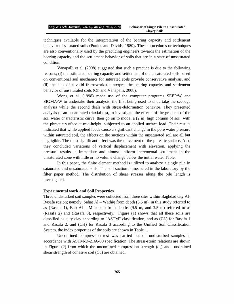
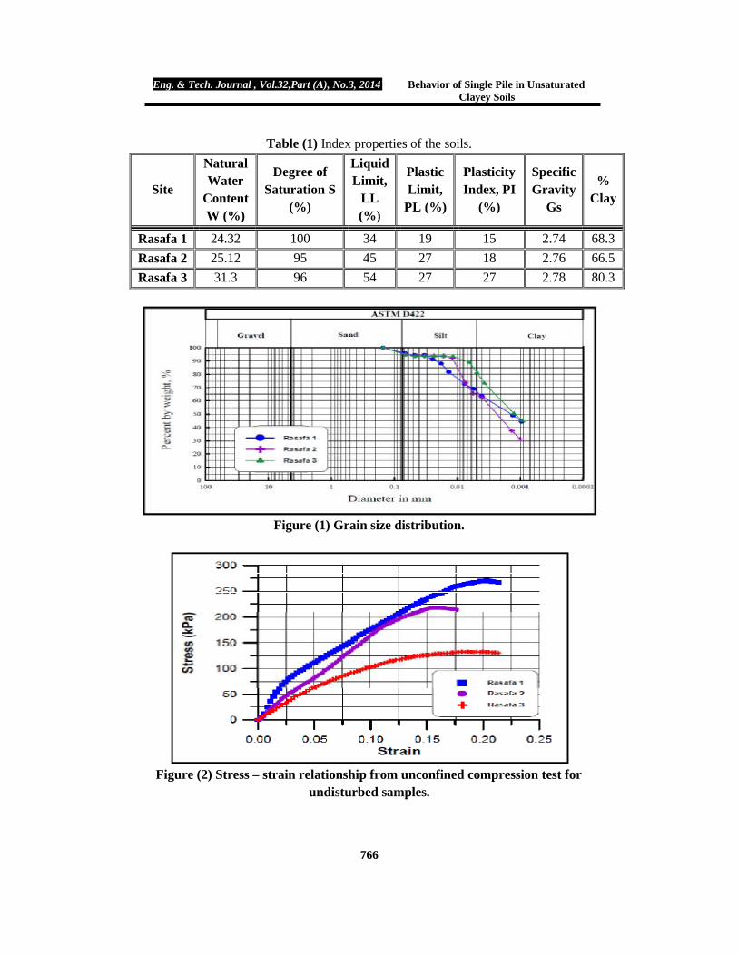
Wong et al. (1998) made use of the computer programs SEEP/W and SIGMA/W to undertake their analysis, the first being used to undertake the seepage analysis while the second deals with stress-deformation behavior. They presented analysis of an unsaturated triaxial test, to investigate the effects of the gradient of the soil water characteristic curve, then go on to model a (2 m) high column of soil, with the phreatic surface at mid-height, subjected to an applied surface load. Their results indicated that while applied loads cause a significant change in the pore water pressure within saturated soil, the effects on the suctions within the unsaturated soil are all but negligible. The most significant effect was the movement of the phreatic surface. Also they concluded variations of vertical displacement with elevation, applying the pressure results in immediate and almost uniform incremental settlement in the unsaturated zone with little or no volume change below the initial water Table. In this paper, the finite element method is utilized to analyze a single pile in sataurated and unsaturated soils. The soil suction is measured in the laboratory by the filter paper method. The distribution of shear stresses along the pile length is investigated. Experimental work and Soil Properties Three undisturbed soil samples were collected from three sites within Baghdad city Al-Rasafa region; namely, Sahat Al – Wathiq from depth (3.5 m), in this study referred to as (Rasafa 1), Bab Al – Muadham from depths (9.5 m, and 3.5 m) referred to as (Rasafa 2) and (Rasafa 3), respectively. Figure (1) shows that all these soils are classified as silty clay according to "ASTM" classification, and as (CL) for Rasafa 1 and Rasafa 2, and (CH) for Rasafa 3 according to the Unified Soil Classification System, the index properties of the soils are shown in Table 1.
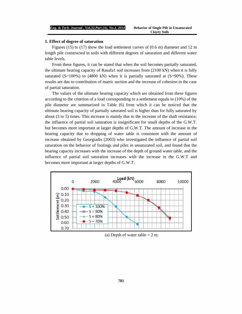
Unconfined compression test was carried out on undisturbed samples in accordance with ASTM-D-2166-00 specification. The stress-strain relations are shown in Figure (2) from which the unconfined compression strength (q u) and undrained shear strength of cohesive soil (Cu) are obtained.
Eng. & Tech. Journal , Vol.32,Part (A), No.3, 2014 Behavior of Single Pile in Unsaturated Clayey Soils
766
Table (1) Index properties of the soils.
Site
Natural Water
Content W (%)
Degree of Saturation S
(%)
Liquid Limit,
LL (%)
Plastic Limit,
PL (%)
Plasticity Index, PI
(%)
Specific Gravity
Gs
% Clay
Rasafa 1 24.32 100 34 19 15 2.74 68.3 Rasafa 2 25.12 95 45 27 18 2.76 66.5 Rasafa 3 31.3 96 54 27 27 2.78 80.3
Figure (1) Grain size distribution.
Figure (2) Stress – strain relationship from unconfined compression test for
undisturbed samples.

Eng. & Tech. Journal , Vol.32,Part (A), No.3, 2014 Behavior of Single Pile in Unsaturated Clayey Soils
767
Measurement of soil suction The soil water characteristic curve (SWCC) defines the relationship between the amount of water in the soil and soil suction. The SWCC has been used as a tool either directly or indirectly in the prediction of the shear strength parameter and coefficient of permeability. The filter paper method is adopted to measure the total and matric suction according to (ASTM D 5298) specification. Glass jars that are between 250 to 500 ml volume sizes are readily available and can be easily adopted for suction measurements. Glass jars, especially, with 3.5 to 4 inch (88.9 to 101.6 mm) diameter can hold the 3 inch (76.2 mm) diameter Shelby tube samples. A testing procedure for total suction measurements using filter papers is outlined following the procedure adopted by Bulut et al. (2001) and Mohsin (2012). Figures (3) and (4) show the test procedure.
b. a.
d. c. Figure (3) Steps of the matric suction measurements (after Mohsin, 2012).

Eng. & Tech. Journal , Vol.32,Part (A), No.3, 2014 Behavior of Single Pile in Unsaturated Clayey Soils
768
Figure (4) Steps of the total suction measurements (after Mohsin, 2012).
Description of the Problem All the analyses involve a single concrete pile in uniform soil. The pile is 12 m long and has 0.6 m diameter with the material properties shown in Table (2).
Table (2) Concrete pile properties (from Cheong and Alvery, 2000). Modulus of
elasticity, Ec (kPa) Poisson’s ratio
(ν) Unit weight
(kN/m3) Cohesion
(kPa) 21250 * 103 0.2 23.5 2700
Finite element description and constitutive model The finite element mesh for the axisymmetric problem is shown in Figure (5). Eight nodded isoparametric quadrilateral elements are used for modeling all the cases. Due to symmetry, only half of the mesh is considered. The right and left hand edges of the mesh are restricted horizontally and the bottom of the mesh is restricted in both horizontal and vertical directions, the top edge is free in both directions.
In this work, two constitutive models are used to characterize the stress-strain behavior of the soil; linear elastic model is used for the pile material and soil existing above the water table, while elastic plastic model with Mohr-Coulomb failure criterion is used for modeling the soil below the water table.
The undrained shear strength (Cu) of each soil was measured by carrying out unconfined compression test through remolding the samples at different degrees of saturation (100%, 90%, 80%, and 70%). The results demonstrate that the unconfined compressive strength (qu) increases with the decrease of the degree of saturation (S), and consequently increase of undrained shear strength (Cu); the results of unconfined compression test are shown in Table (3) and Figure (6) for Rasafa1 soil. Similar relations were obtained for Rasafa2 and Rasafa3 soils.
The pile is assumed to be constructed in saturated and unsaturated soils. The undisturbed soil samples obtained from three sites in Baghdad having different degrees

Eng. & Tech. Journal , Vol.32,Part (A), No.3, 2014 Behavior of Single Pile in Unsaturated Clayey Soils
769
of saturation, the undisturbed samples have material properties shown in Table (4) as obtained from laboratory tests carried out on these undistributed samples.
Table (3) Results of unconfined compression test on remolded samples at different
degrees of saturation. Type of Soil S (%) qu (kPa) Cu (kPa) E (kPa)
Rasafa 1
100% 270 135 135000 90% 287 143.5 143500 80% 311 155.5 155500 70% 329 164.5 164500
Rasafa 2
100% 205 102.5 102500 90% 227 113.5 113500 80% 238 119 119000 70% 252 126 126000
Rasafa 3
100% 130 65 65000 90% 151 75.5 75500 80% 164 82 82000 70% 176 88 88000
Required Relationships for Unsaturated Soils There are some relationships that are required in dealing with partially saturated soil characteristics, these are: 1. Suction with degree of saturation Total and matric suction of each soil sample were measured by remodeling the samples at different degrees of saturation (70%, 80%, 90% and 20%) using filter paper method (Whatman No. 42) according to the procedure of (ASTM D 5298-03). Figures (7) and (8) show the relationship between total and matric suction and the degree of saturation, respectively.
From these figures, it can be noticed that the suction of soil decreases with the increase in the degree of saturation and the rate of increase in matric suction of Rasafa1 is greater than the rate for Rasafa2 and Rasafa3 for the same degree of saturation. This is due to the difference in physical properties for each soil. Rasafa1 has a value of density greater than the other two sites, high value of density results in high values of suction. This is due to increase in clay content and decrease in the distance among the soil particles (Fattah et al., 2013).

Eng. & Tech. Journal , Vol.32,Part (A), No.3, 2014 Behavior of Single Pile in Unsaturated Clayey Soils
770
Figure (5) Typical finite element mesh of the pile-soil system.
Figure (6) Results of unconfined compression test on remolded samples from
(Rasafa 1) site at different degrees of saturation.

Eng. & Tech. Journal , Vol.32,Part (A), No.
Table (4) Material properties for three soils of study.Type of Soil Parameter
Rasafa 1
Total unit weight, (γDry unit weight, (γ
Angle of internal friction, (ø)Poisson's ratio, (ν)
Poisson's ratio, (ν)Hydraulic conductivity, (
Void ratio, (e)Coefficient of volume change (
Rasafa 2
Total unit weight, (γDry unit weight, (γ
Angle of internal friction, (ø)Poisson's ratio, (ν)
Poisson's ratio, (ν)Hydraulic
Void ratio, (e)Coefficient of volume change (
Rasafa 3
Total unit weight, (γDry unit weight, (γ
Angle of internal friction, (ø)Poisson's ratio,
Poisson's ratio, (ν)Hydraulic conductivity, (
Void ratio, (e)Coefficient of volume change (
Assumed values (according to Bowles, 2. H-Modulus function
The H is the unsaturated modulus that relates the volumetric strain of the soil to a change in negative pore water pressure or change in suction. The Hbe defined as a function of negative porethe elastic constants E and υ by the equation:
Eng. & Tech. Journal , Vol.32,Part (A), No.3, 2014 Behavior of Single Pile in Unsaturated Clayey Soils
771
Table (4) Material properties for three soils of study. Parameter Value Unit
Total unit weight, (γt) 20.21 kN/mDry unit weight, (γd) 16.25 kN/m
Angle of internal friction, (ø) 0 DegreePoisson's ratio, (ν)٭ for saturated soil 0.45٭ ―
Poisson's ratio, (ν)٭ for unsaturated soil 0.3٭ ― Hydraulic conductivity, (k) 2.55×10⁻¹⁰ m/sec
Void ratio, (e) 0.666 ― Coefficient of volume change (mv) 0.646 m2/MN
Total unit weight, (γt) 19.57 kN/mDry unit weight, (γd) 15.64 kN/m
Angle of internal friction, (ø) 0 DegreePoisson's ratio, (ν)٭ for saturated soil 0.45٭ ―
Poisson's ratio, (ν)٭ for unsaturated soil 0.3٭ ― Hydraulic conductivity, (k) 2.78×10⁻¹⁰ m/sec
Void ratio, (e) 0.73 ― Coefficient of volume change (mv) 0.58 m2/MN
Total unit weight, (γt) 18.82 kN/mDry unit weight, (γd) 14.33 kN/m
Angle of internal friction, (ø) 0 DegreePoisson's ratio, (ν)٭ for saturated soil 0.45٭ ―
Poisson's ratio, (ν)٭ for unsaturated soil 0.3٭ ― Hydraulic conductivity, (k) 2.85×10⁻¹⁰ m/sec
Void ratio, (e) 0.903 ― Coefficient of volume change (mv) 0.716 m2/MN
according to Bowles, 1996).
The H is the unsaturated modulus that relates the volumetric strain of the soil to a change in negative pore water pressure or change in suction. The H-modulus may be defined as a function of negative pore-water pressure. At saturation, H is related to the elastic constants E and υ by the equation:
Unit kN/m3
kN/m3
Degree
m/sec
/MN kN/m3
kN/m3
Degree
m/sec
/MN kN/m3
kN/m3
Degree
m/sec
/MN
The H is the unsaturated modulus that relates the volumetric strain of the soil modulus may
saturation, H is related to

Eng. & Tech. Journal , Vol.32,Part (A), No.
Figure (7) Relationship between the total suction and degree of saturation for the
Figure (8) Relationship betweensaturation for the three soils.
Therefore, H must be set to E / (1
2004). When defining an H-Modulus with pore water pressure function, as a soil dries and the pore water pressure becomes highly negative, the soil becomes very stiff. This increase in stiffness is represented by an increase in H.
There are sets of steps considered to find the Hare proposed in this work in order to characterize the be
Eng. & Tech. Journal , Vol.32,Part (A), No.3, 2014 Behavior of Single Pile in Unsaturated Clayey Soils
772
… (1)
Figure (7) Relationship between the total suction and degree of saturation for the
three soils.
Figure (8) Relationship between the matric suction and degree of saturation for the three soils.
Therefore, H must be set to E / (1 – 2 υ) at zero pore water pressure (Krahn, Modulus with pore water pressure function, as a soil dries
e becomes highly negative, the soil becomes very stiff. This increase in stiffness is represented by an increase in H.
There are sets of steps considered to find the H-modulus function. These steps are proposed in this work in order to characterize the behavior of unsaturated soils:
Figure (7) Relationship between the total suction and degree of saturation for the
) at zero pore water pressure (Krahn, Modulus with pore water pressure function, as a soil dries
e becomes highly negative, the soil becomes very stiff. This
modulus function. These steps

Eng. & Tech. Journal , Vol.32,Part (A), No.
1. From the program (Soil Vision), and after inputting all the required properties of the soils used in this analysis, (i.e., total unit weight, dry unit weight, liquid limit, plasticity index, void ratio, porosity, matric suctiongrain size distribution), the soil water characteristic curve is predicted (relation between the gravitation water content and the matric suction) through applying fitting methods, such as the method proposed by Fredlund aGenuchten (1980) for fitting the soil water characteristic curve
2. The previous relations are converted to relations correlating the void ratio and the
matric suction based on the relation:
e = where w= gravitation water content, Gs = specific gravity of soil solids, and S = degree of saturation. Then, the slope of the void ratio versus the matric suction, m is predicted:
m = where: e = (e2 – e1),
hm = (hm1 - hm2), hm1, hm2 are the initial and final matric suctions, respectively, and e1, e2 are the initial and final void ratios, respectively.
Figure (10) shows the steps followed to find the slope of the void ratio versus the matric suction relation for Rasafa2
3. After finding the slope of the segments on the curve of void ratio versus the matric suction of different types of the soil, it can be seen
(Krahn, 2004): Hence, the H-modulus function becomes:
where: n = porosity of soil, and
m = the slope of the void ratio versus the matric suction.The H-modulus functions for the three soils are shown
Eng. & Tech. Journal , Vol.32,Part (A), No.3, 2014 Behavior of Single Pile in Unsaturated Clayey Soils
773
From the program (Soil Vision), and after inputting all the required properties of the soils used in this analysis, (i.e., total unit weight, dry unit weight, liquid limit, plasticity index, void ratio, porosity, matric suction value, degree of saturation, and grain size distribution), the soil water characteristic curve is predicted (relation between the gravitation water content and the matric suction) through applying fitting methods, such as the method proposed by Fredlund and Xing (1994) and Van Genuchten (1980) for fitting the soil water characteristic curve see (Figure 13).
The previous relations are converted to relations correlating the void ratio and the matric suction based on the relation:
…. (2)
= gravitation water content, = specific gravity of soil solids, and
Then, the slope of the void ratio versus the matric suction, m is predicted:
… (3)
are the initial and final matric suctions, respectively, and are the initial and final void ratios, respectively.
) shows the steps followed to find the slope of the void ratio versus the Rasafa2 soil.
After finding the slope of the segments on the curve of void ratio versus the matric suction of different types of the soil, it can be seen that each slope, m is equal to
modulus function becomes:
… (4)
m = the slope of the void ratio versus the matric suction. ns for the three soils are shown in Figure (11).
From the program (Soil Vision), and after inputting all the required properties of the soils used in this analysis, (i.e., total unit weight, dry unit weight, liquid limit,
value, degree of saturation, and grain size distribution), the soil water characteristic curve is predicted (relation between the gravitation water content and the matric suction) through applying
nd Xing (1994) and Van
The previous relations are converted to relations correlating the void ratio and the
) shows the steps followed to find the slope of the void ratio versus the
After finding the slope of the segments on the curve of void ratio versus the matric that each slope, m is equal to

Eng. & Tech. Journal , Vol.32,Part (A), No.
a. Using Fredlund and Xing (1994)fitting for Rasafa 1.
c. Using Fredlund and Xing (1994)fitting for Rasafa 2.
e. Using Fredlund and Xing (1994)fitting for Rasafa 3.
Figure (9) Relationships between suction for different soil types obtained by the program Soil Vision.
Eng. & Tech. Journal , Vol.32,Part (A), No.3, 2014 Behavior of Single Pile in Unsaturated Clayey Soils
774
a. Using Fredlund and Xing (1994)
b. Using Van Genuchten (1980) fitting for Rasafa 1.
Using Fredlund and Xing (1994)
d. Using Van Genuchten (1980)
fitting for Rasafa 2.
e. Using Fredlund and Xing (1994)
f. Using Van Genuchten (1980) fitting for Rasafa 3.
Figure (9) Relationships between the gravitational water content and the matric suction for different soil types obtained by the program Soil Vision.

Eng. & Tech. Journal , Vol.32,Part (A), No.3, 2014 Behavior of Single Pile in Unsaturated Clayey Soils
775
Figure (10) Relationships between void ratio and matric suction for Rasafa2 soil.
(a) Rasafa 1
(b) Rasafa 2

Eng. & Tech. Journal , Vol.32,Part (A), No.
Figure (11) Relations between the H
3. Volumetric water content In soil science, volumetric water content is most commonly used. In geotechnical
engineering practice, gravimetric water content water to the mass of solids, is most commonly used. Fredlund and Rahardjo (1993), defined the volumetric water content as the ratio of volume of water, volume of the soil,
θw =
The volumetric water content can also be expressed in terms of specific gravity, Gvoid ratio, e, and water content as a function of soil suction:
θw = where: w(h) = gravimetric water content as a function of matric suction of soil.
One of required input data in SEEP/W program is relationship between volumetric water content and pore water pressure. SEEP/W can estimate input data such as, volumetric water content at saturated condition, θof volume change, mv, and from closed form solution of Van Genuchten (1980), or Fredlund and Xing (1994).The four parameters semi log plot of the soil water characteristic curve. First, the suction corresponding to the residual water content locating a point where the curve starts to drop linthe inflection point (hi, θi) is located on the semi log plot and a tangent line is drawn
Eng. & Tech. Journal , Vol.32,Part (A), No.3, 2014 Behavior of Single Pile in Unsaturated Clayey Soils
776
(c) Rasafa 3
Figure (11) Relations between the H-modulus and the matric suction for different soil types.
In soil science, volumetric water content is most commonly used. In geotechnical engineering practice, gravimetric water content w, which is the ratio of the mass of water to the mass of solids, is most commonly used. Fredlund and Rahardjo (1993),
the volumetric water content as the ratio of volume of water, Vw, to the total
… (5)
The volumetric water content can also be expressed in terms of specific gravity, G s, void ratio, e, and water content as a function of soil suction:
… (6)
= gravimetric water content as a function of matric suction of soil. One of required input data in SEEP/W program is relationship between volumetric
water content and pore water pressure. SEEP/W can estimate this relationship from input data such as, volumetric water content at saturated condition, θs, and coefficient
, and from closed form solution of Van Genuchten (1980), or Fredlund and Xing (1994).The four parameters a, n, m and hr, can be obtained from a semi log plot of the soil water characteristic curve. First, the suction corresponding to the residual water content hr, is determined by
locating a point where the curve starts to drop linearly in the high suction range. Next, ) is located on the semi log plot and a tangent line is drawn
modulus and the matric suction for different soil
In soil science, volumetric water content is most commonly used. In geotechnical , which is the ratio of the mass of
water to the mass of solids, is most commonly used. Fredlund and Rahardjo (1993), , to the total
,
One of required input data in SEEP/W program is relationship between volumetric this relationship from
, and coefficient , and from closed form solution of Van Genuchten (1980), or
be obtained from a
, is determined by . Next,
) is located on the semi log plot and a tangent line is drawn

Eng. & Tech. Journal , Vol.32,Part (A), No.
through this point. Then the fitting parameters follows:
where: θs = volumetric water content at saturated condition, and hi = the suction corresponding to infection point.
=
The slope, s, of the tangent line can be calculated as follows:
s = where:
hp = intercept of the tangent line on the semi log plot on matric suction axis.Figure (12) shows the estimated relation between the volumetric water content and
matric suction (negative pore water pressure for the sobetween the volumetric water content andrelationship between the hydraulic conductivity and pore water pressure can be estimated. This relation is shown in Figure (13
Eng. & Tech. Journal , Vol.32,Part (A), No.3, 2014 Behavior of Single Pile in Unsaturated Clayey Soils
777
through this point. Then the fitting parameters a, n, and m can be determined as
….. (7)
…. (8)
… (9)
= volumetric water content at saturated condition, and = the suction corresponding to infection point.
… (10)
The slope, s, of the tangent line can be calculated as follows:
… (11)
= intercept of the tangent line on the semi log plot on matric suction axis. ) shows the estimated relation between the volumetric water content and
matric suction (negative pore water pressure for the soils). After estimating the relation between the volumetric water content and pore water pressure, Figure (12), a relationship between the hydraulic conductivity and pore water pressure can be
relation is shown in Figure (13) for the three soils.
(a) Rasafa 1
can be determined as
… (9)
) shows the estimated relation between the volumetric water content and ils). After estimating the relation
), a relationship between the hydraulic conductivity and pore water pressure can be

Eng. & Tech. Journal , Vol.32,Part (A), No.3, 2014 Behavior of Single Pile in Unsaturated Clayey Soils
778
(b) Rasafa 2
(c) Rasafa 3
Figure (12) Relationships between volumetric water content and matric suction for the three soils.
(a) Rasafa 1

Eng. & Tech. Journal , Vol.32,Part (A), No.
Figure (13) Relation between the hydraulic conductivity and pore water pressure for partially saturated soils of the three sites.
Finite Elements Analysis of Piles in Unsaturated SoilsEach type of soil was analyzed first as fully saturated soil by the programs SIGMA/W and SEEP/W. The results shown in Figure (1failure mechanism is close to the punching shear failure mode and the ultimate bearing capacity according to the criterion(10%) of the pile diameter is in a good agreement with bearing capacity equation for piles in cohesive soil. A modified Terzaghi bearing capacity equation is used to find the pile capacity:-
where: Pu = ultimate pile capacity, Qu = ultimate end bearing capacity,
Eng. & Tech. Journal , Vol.32,Part (A), No.3, 2014 Behavior of Single Pile in Unsaturated Clayey Soils
779
(b) Rasafa 2
(c) Rasafa 3
Figure (13) Relation between the hydraulic conductivity and pore water pressure for partially saturated soils of the three sites.
Finite Elements Analysis of Piles in Unsaturated Soils first as fully saturated soil by the programs SIGMA/W
and SEEP/W. The results shown in Figure (14) and Table (5) demonstrate that the failure mechanism is close to the punching shear failure mode and the ultimate bearing capacity according to the criterion of the load corresponding to settlement equal to (10%) of the pile diameter is in a good agreement with bearing capacity equation for piles in cohesive soil. A modified Terzaghi bearing capacity equation is used to find
… (12) … (13)
Qu = ultimate end bearing capacity,
Figure (13) Relation between the hydraulic conductivity and pore water pressure
first as fully saturated soil by the programs SIGMA/W ) and Table (5) demonstrate that the
failure mechanism is close to the punching shear failure mode and the ultimate bearing of the load corresponding to settlement equal to
(10%) of the pile diameter is in a good agreement with bearing capacity equation for piles in cohesive soil. A modified Terzaghi bearing capacity equation is used to find

Eng. & Tech. Journal , Vol.32,Part (A), No.
Su = ultimate skin friction, c = cohesion of the soil, Ac = cross sectional area of the pile, α =adhesion factor between pile and soil, andAp = shaft area along the pile.
Effect of water table and degree of saturation on the capacity of pile is studied for
the three types of soil, for each type of soil, the depth of water table is varied (2 m,4 m,6 m, and 12 m) and (70%, 80%, and 90%) degrees of saturation for soil atable were analyzed.
Table (5) Results of analysis of the capacity of piles in saturated soils.
Soil type according to Equation
Rasafa 1 Rasafa 2 Rasafa 3
Figure (14) Load settlement curves of (0.6m) diameter pile in different types of
Eng. & Tech. Journal , Vol.32,Part (A), No.3, 2014 Behavior of Single Pile in Unsaturated Clayey Soils
780
Ac = cross sectional area of the pile, α =adhesion factor between pile and soil, and
= shaft area along the pile.
Effect of water table and degree of saturation on the capacity of pile is studied for the three types of soil, for each type of soil, the depth of water table is varied (2 m,4 m,6 m, and 12 m) and (70%, 80%, and 90%) degrees of saturation for soil above water
Table (5) Results of analysis of the capacity of piles in saturated soils.
according to Equation (13) (kN)
corresponding to settlement of 10% of pile diameter (kN)
1565 2100 1246 1100 765 1300
Figure (14) Load settlement curves of (0.6m) diameter pile in different types of
fully saturated soils.
Effect of water table and degree of saturation on the capacity of pile is studied for the three types of soil, for each type of soil, the depth of water table is varied (2 m,4
bove water
Eng. & Tech. Journal , Vol.32,Part (A), No.3, 2014 Behavior of Single Pile in Unsaturated Clayey Soils
781
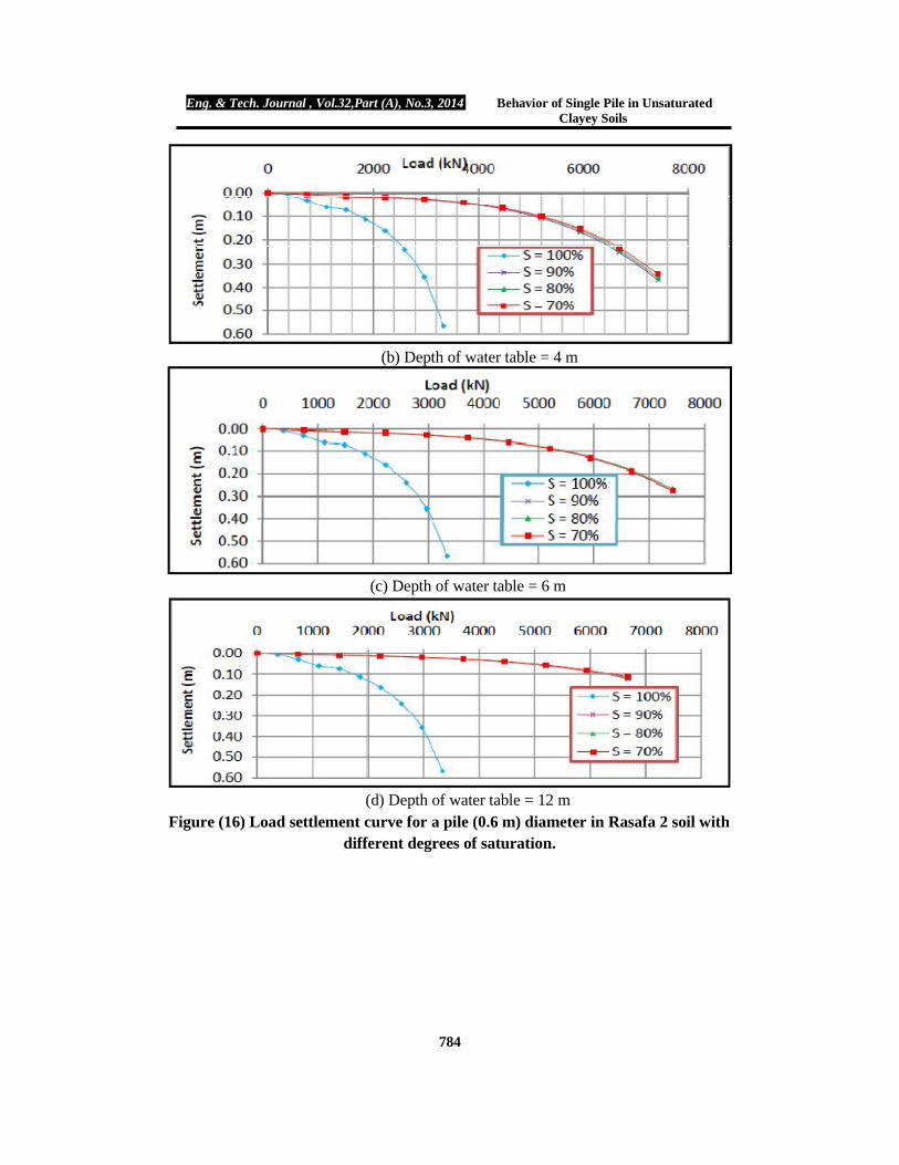
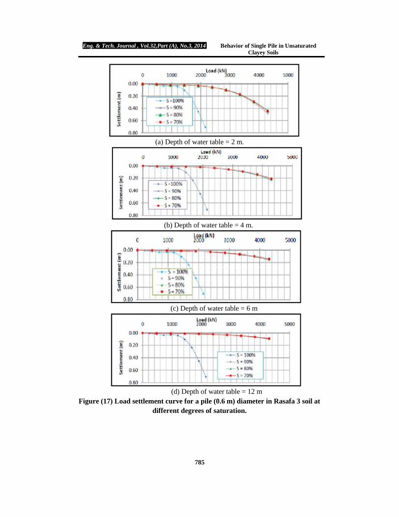
1. Effect of degree of saturation Figures (15) to (17) show the load settlement curves of (0.6 m) diameter and 12 m
length pile constructed in soils with different degrees of saturation and different water table levels.
From these figures, it can be stated that when the soil becomes partially saturated, the ultimate bearing capacity of Rasafa1 soil increases from (2100 kN) when it is fully saturated (S=100%) to (4800 kN) when it is partially saturated at (S=90%). These results are due to contribution of matric suction and the increase of cohesion in the case of partial saturation.
The values of the ultimate bearing capacity which are obtained from these figures according to the criterion of a load corresponding to a settlement equals to (10%) of the pile diameter are summarized in Table (6) from which it can be noticed that the ultimate bearing capacity of partially saturated soil is higher than for fully saturated by about (3 to 5) times. This increase is mainly due to the increase of the shaft resistance; the influence of partial soil saturation is insignificant for small depths of the G.W.T. but becomes more important at larger depths of G.W.T. The amount of increase in the bearing capacity due to dropping of water table is consistent with the amount of increase obtained by Georgiadis (2003) who investigated the influence of partial soil saturation on the behavior of footings and piles in unsaturated soil, and found that the bearing capacity increases with the increase of the depth of ground water table, and the influence of partial soil saturation increases with the increase in the G.W.T and becomes more important at larger depths of G.W.T.
(a) Depth of water table = 2 m.

Eng. & Tech. Journal , Vol.32,Part (A), No.3, 2014 Behavior of Single Pile in Unsaturated Clayey Soils
782
(b) Depth of water table = 4 m.
(c) Depth of water table = 6 m.
(d) Depth of water table = 12 m.
Figure (15) Load settlement curve for a pile (0.6 m) diameter in Rasafa 1 soil with different degrees of saturation.

Eng. & Tech. Journal , Vol.32,Part (A), No.3, 2014 Behavior of Single Pile in Unsaturated Clayey Soils
783
Table (6) Results of ultimate capacity (kN) for piles constructed in soils of different degrees of saturation as obtained from finite element analysis.
W.T depth Degree of saturation Rasafa 1 Rasafa 2 Rasafa 3
0 m 100 % 2100 1100 1300
2 m 90 % 4800 3600 2420 80 % 4780 3600 2450 70 % 4800 3600 2500
4 m 90 % 5400 4200 2820 80 % 5520 4300 2950 70 % 5600 4400 2950
6 m 90 % 5800 4430 3070 80 % 6000 4500 3180 70 % 6100 4480 3250
12m 90% 6500 5200 3600 80% 6700 5270 3700 70% 6800 5400 3780
(a) Depth of water table = 2 m
Eng. & Tech. Journal , Vol.32,Part (A), No.3, 2014 Behavior of Single Pile in Unsaturated Clayey Soils
784
(b) Depth of water table = 4 m
(c) Depth of water table = 6 m
(d) Depth of water table = 12 m
Figure (16) Load settlement curve for a pile (0.6 m) diameter in Rasafa 2 soil with different degrees of saturation.
Eng. & Tech. Journal , Vol.32,Part (A), No.3, 2014 Behavior of Single Pile in Unsaturated Clayey Soils
785
(a) Depth of water table = 2 m.
(b) Depth of water table = 4 m.
(c) Depth of water table = 6 m
(d) Depth of water table = 12 m
Figure (17) Load settlement curve for a pile (0.6 m) diameter in Rasafa 3 soil at different degrees of saturation.

Eng. & Tech. Journal , Vol.32,Part (A), No.3, 2014 Behavior of Single Pile in Unsaturated Clayey Soils
786
Conclusions 1. From the experimental work, the soil water characteristic curve was obtained by
the filter paper method for Rasafa 1, Rasafa 2, and Rasafa 3 soils. Soil suction increases as the degree of saturation decreases for the three soils; Rasafa 1 has a value of matric suction more than the other soils due to its small void ratio. For each type of soil, the values of shear strength that are measured by unconfined compression test are greater for samples with smaller degrees of saturation than the higher degrees of saturation.
2. The procedure of analysis of the capacity of pile foundation in partially saturated soil by finite elements requires a proposed procedure to define the H – modulus function. The procedure followed in this work is found to be successful through the encouraging results of the problem under consideration.
3. The change in the water table level and the degree of saturation has a great effect on the behavior of partially saturated soil. In this work, it is found that due to dropping of water table and contribution of matric suction (i.e. negative pore water pressure), the capacity of piles in partially saturated soil is approximately (3-5) times the capacity of piles in the same soil under saturated conditions.
4. A linear increase in the capacity of piles is obtained due to lowering of water table and non linear increase due to change in matric suction for the same depth of water table. The increase in the pile capacity due to lowering of water table is greater than the increase due to matric suction. A linear increase in the capacity of piles is obtained due to lowering of water table and non linear increase due to change in matric suction for the same depth of water table. The increase in the pile capacity due to lowering of water table is greater than the increase due to matric suction.
REFERENCES [1].ASTM – D – 2166 – 00. "Standard Test Method for Unconfined Compressive Strength of Cohesive Soil", Annual Book of ASTM Standards,Vol. 04–08, Soil and Rock, pp.1 – 7. [2].ASTM-D-5298-03, "Standard Test Method for Measurement of Soil Potential (Suction) Using Filter Paper", Annual Book of ASTM Standards, Vol. 04.08, Soil and Rock, pp. 1 – 6. [3].Bowles, J.E., (1996), "Foundation Analysis and Design", 5 McGraw Hill Book Company. Inc. New York pp. 127. [4].Bulut, R., Lytton, R.L., and Warren, K., (2001), "Soil Suction Measurement by Filter Paper" Geo. Special Publication Number 115, pp. 1-64. [5].Cheong, H.K. and Alevey N.M., (2000), " Experimental Behavior Of Jacked Reinforced Concrete Beams", Journal of Structural Engineering, June, Vol. 126, No.6 pp. 692 – 699. [6].Das, B.M., (2008), "Principle of Geotechnical Engineering". [7].Fredlund, D.G., and Rahardjo, H. (1993), "Soil Mechanics for Unsaturated Soils". John Wiley and Sons, Inc. New York, United States of America. Curve", University of Saskatchewan, Canda. [8].Fredlund, D.G., and Xing, A. (1994), "Equations for the Soil Water Characteristic
Eng. & Tech. Journal , Vol.32,Part (A), No.3, 2014 Behavior of Single Pile in Unsaturated Clayey Soils
787
Curve", University of Saskatchewan, Canda. [9].Georgiadis, K. (2003), "Development, Implementation and Application of Partially Saturated Soils Models in Finite Element Analysis". MSc. Thesis, University of London. [10].Krahn, J., (2004), "Stress And Deformation Modeling With SIGMA/W", GEO –SLOPE International, Ltd. [11].Lu, N., and Likos, W.J., (2004), "Unsaturated Soil Mechanics", John Wiley and Sons, New York. [12].Mohsen, I. M., (2012), “Behavior of Single Pile in Unsaturated Clay Soils”, M.Sc. Thesis, Building and Construction Engineering Department, University of Technology, Iraq. [13].Nelson, J.D. and Miller, D.J., (1992), "Expansive Soils". John Wiley and Sons. [14].Oh, W.T., and Vanapalli, S.K. (2008), "Modeling the Stress versus Settlement Behavior of Model Footings In Saturated And Unsaturated Sandy Soils", The 12th International Conference International Conference of International Association for Computer Methods and Advance in Geomechanics. (IACMAG), Goa, India. [15].Poulos, H.G., and Davis, E.H., (1980), "Pile Foundation Analysis And Design". University of Sydney. [16].Vanapalli, S.K., Oh, W.T., and Puppla, A.J. (2008), "A Simple Method for the Prediction of Modulus of Elasticity for Unsaturated Soils". Proc. 1st Int. European Conf. on Unsaturated Soils. [17].Van Genuchent, M. T., (1980), "A Closed Form Equation for Prediction of the Hydraulic Conductivity of Unsaturated Soils", Soil Science Society America Journal, 44, pp. 892 – 898. [18].Wong, T.T., Fredlund, D.G., and Krahn, J., (1998), "A Numerical Study of Coupled Consolidation in Unsaturated Soils", Canadian Geotechnical Journal, Vol. 35, pp. 926– 937.