behavior of reinforced modified reactive powder concrete ... · pdf filejournal of engin...
TRANSCRIPT

Journal of Engineering and Development, Vol.19, No.2, march. 2015, ISSN 1813- 7822
154
Behavior of Reinforced Modified Reactive Powder Concrete
Knee Joints Asst. Prof. Dr. Jasim Mahmud Al-Khafaji Lec.Dr. Haider Abdul Ameer
Civil Eng. Dept. Civil Eng. Dept.
Al- Mustansiriyah University Al- Mustansiriyah University
Wael Shahatha
Environmental Eng. Dept.
Al-Mustansiriyah University
Abstract
This investigation presents an experimental study of strength and behavior of
Modified Reactive Powder Concrete (MRPC) corner subjected to bending moment tended
to open the angle. Twelve specimens are tested to study the corner strength, cracks types,
cracking moment, cracks patterns, corner deflection, ductility and corner efficiency. Ten
MRPC knee joints were mixture of steel fiber, superplasticized, silica fume-cement
blended with very low water/cement ratio (w/c) characterized by very fine sand (maximum
size 600µm), where the presence of natural crushed aggregate of maximum size (4.75mm)
was used to replace a part of the fine sand. The rest two corners of Normal Strength
Concrete (NSC) which are the mixture of (1:1.5:3) (cement : sand 4.75mm : gravel
10mm). The specimens are designed to represent an actual prototype of a portal frame
corner. The compressive strength of concrete in the test varies from (23.5) to (88.9) MPa,
and steel tension ratio in legs is constant, ρ = 0.008, for ten specimens where the two
MRPC corners are plain concrete. The specimens are designed to represent an actual
prototype of a portal frame corner. The nominal dimensions of the tested corners are
(1078 mm) in overall length, (600 mm) in height, the cross section of the corner is
rectangular (212×150mm). All corners are supported to be hinged in one leg by two
clamps and rolled in other leg, also all corners are loaded by steel frame where, it
produces moment tends to open the angle. Concrete strains are recorded for each tested
corner; also load deflection curves were plotted. Throughout the test operation crack

Journal of Engineering and Development, Vol.19, No.2, march. 2015, ISSN 1813- 7822
155
patterns were drawn and the mode of failure of the tested corners is identified, which is
divided into two types (flexural and bearing) failure. It was found that enhance the properties
of concrete for corner block improve efficiency to be such an alternative solution for corner
block contain stirrups and complicated details of rebar. Depending on the results of the
current experimental work a suff ic ien t corner was recommended for building subjected
to seismic and earthquake regions.
Keywords: NSC, MRPC, Corner, Steel fiber, Silica Fume, ratio of fine sand to fine gravel.
مسلحة قائمة الزاوية من خرسانة المساحيق الفعالة المعدلة سلوك وصالت خرسانية
األمير حيدر عبد . د الخفاجي محمود جاسم .د.م.ا
المستنصرية الجامعة/المدنية الهندسة قسم المستنصرية الجامعة/المدنية الهندسة قسم
عبد الكريم وائل شحاذة
المستنصرية الجامعة/البيئةدسة هن قسم
:ةالخالص
الخرسانية لألركان التسليح تفاصيل من متعددة أنواع وتصرف لمقاومة عملية دراسة الحالي البحث يستعرض
نوع الخرسانة، مقاومة تأثير لدراسةنموذج (12) فحص تم .الزاوية فتح على تعمل إنحناء لعزوم المعرضة
النماذج صممت .وكفاءته الخرساني الركن هطولباالضافة الى المطيلية التشققات، أشكال ،التشققات عزوم التشققات،وللخرسانة الفعالة ) ميكا باسكال 23.5( الخرسانة العادية إنضغاط مقاومة .اإلنشائية الهياكل أركان وتحاكي تمثل لكي
0.008وتساوي ثابتة كانت األركان يقانس في الشد حديد ونسبة،ميكا باسكال 88.9) و 55.3(بين تراوحت المعدلةالنماذج صممت .مفحوصة تحتوي على حديد التسليح في حين كان نموذجين خاليين من حديد التسليح نماذج لعشرة
) ملم 150(لالرتفاع و) ملم 600(طوال و ) ملم 1078(أبعاد النمـاذج هــي ،اإلنشائية الهياكل أركان وتحاكي تمثل لكي أسندت). ملم 212×150(ومستطيال في القاعدة ) ملم 150×150(العرضي كان مربعا في الساق مقطعال إما. سمكا
تحميل تم. متحرك بمفصل األخرى الجهة وأسندت عقفتين بإستخدام السيقان أحد في مفصلي شكل على األركان جميع
تحميل مراحل لعدة اإلنفعاالت تسجيل تم. الزاوية فتح على يعمل عزم بتوليد يقوم فوالذي هيكل بواسطة األركان جميع
في الحاصلة التشققات رسم تم الفحص عملية أثناء .واإلزاحة الحمل منحيات رسم وتم كما فحصه تم ركن ولكل مختلفة
).إرتكاز أو إنحناء فشل(نوعين على كانت والتي الحاصلة الفشل نوعية وتحديد الخرساني الركن
Journal of Engineering and Development, Vol.19, No.2, march. 2015, ISSN 1813- 7822
156
حديد القص والتفاصيل المعقدة لحديد لتقليلكبديل يؤدي الى زيادة الكفاءة سانةالخرتحسين خواص بأن تبين لقد الفشل ونوع مقاومة علىباالضافة الى تاثيرها الزاوية فتح على تعمل انحناء لعزوم المعرضةالتسليح في االركان
. الخرساني الركن في الحاصل
احد النماذج باعتباره مناسب لالعمال االنشائية إختيار مت الحالي البحث من المستحصلة النتائج على باإلعتماد .الخاصة لالبنية المعرضة للهزات والزالزل االرضية
NOMENCLATURE
bf =Width of compression face of member, (mm)
D =distance from extreme compression fiber to centroid of longitudinal tension reinforcement,
(mm)
f'c= cylinder compressive strength of concrete, (MPa)
fy= specified yield strength of reinforcement, (MPa)
Mcr=first cracking moment, (kN.m)
(Mcr)R =first cracking moment of reference corner, (kN.m)
Mu=ultimate moment at section, (kN.m)
(Mu)R =ultimate moment of reference corner, (kN.m)
INTRODUCTION
The joint formed from two adjacent members at 90 P
oP usually refers to the "corner". The
terms ''opening'' and ''closing'' the corner are used to describe the increase and decrease of this
right angle P
[1]P, respectively. Concrete corners are found in wide variety of structures such as
retaining walls, bridges and portal frame buildings. They are also common in the field of
hydraulic structures, such as reservoirs, tanks, flumes and culverts. In general, the failure of
opening corners is invariably characterized by the low tensile strength of concrete resulting in the
initiation of a splitting tensile crack originating at the reentrant corner and gradually moves out
along the corner diagonal towards the exterior corner P
[2] and [3]P.
Journal of Engineering and Development, Vol.19, No.2, march. 2015, ISSN 1813- 7822
157
Dimensions of Tested Corners
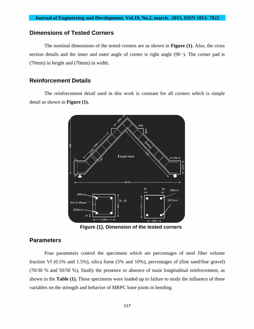
The nominal dimensions of the tested corners are as shown in Figure (1). Also, the cross
section details and the inner and outer angle of corner is right angle (90 °). The corner pad is
(70mm) in height and (70mm) in width.
Reinforcement Details The reinforcement detail used in this work is constant for all corners which is simple
detail as shown in Figure (1).
Figure (1), Dimension of the tested corners
Parameters
Four parameters control the specimens which are percentages of steel fiber volume
fraction Vf (0.5% and 1.5%), silica fume (5% and 10%), percentages of (fine sand/fine gravel)
(70/30 % and 50/50 %), finally the presence or absence of main longitudinal reinforcement, as
shown in the Table (1). These specimens were loaded up to failure to study the influence of these
variables on the strength and behavior of MRPC knee joints in bending.

Journal of Engineering and Development, Vol.19, No.2, march. 2015, ISSN 1813- 7822
158
Table (1) Properties of tested corners Corners
No. G11 G12 G21 G22 G31 G32 G41 G42 G51 G52 G61 G62
Status NSC* NSC MRPC** MRPC MRPC MRPC MRPC MRPC MRPC MRPC MRPC MRPC Tension Rebar
2Ф10 mm
2Ф10 mm
2Ф10 mm
2Ф10 mm
2Ф10 mm
2Ф10 mm
2Ф10 mm
2Ф10 mm
2Ф10 mm
2Ф10 mm Nil Nil
Cement content kg/mP
3 400 400 900 900 900 900 900 900 900 900 900 900
Sand 4.75 mm (kg/mP
3P) 600 600 --- --- --- --- --- --- --- --- --- ---
Gravel 10 mm (kg/mP
3P) 1200 1200 --- --- --- --- --- --- --- --- --- ---
Fine sand 0.6mm (kg/mP
3P)
% of Total Aggregate
--- --- 693
70
495
50
693
70
495
50
693
70
495
50
693
70
495
50
693
70
495
50
Fine gravel 4,75mm (kg/mP
3P)
% of Total Aggregate
--- --- 297
30
495
50
297
30
495
50
297
30
495
50
297
30
495
50
297
30
495
50
Total aggregate
(kg/mP
3P)
--- --- 990 990 990 990 990 990 990 990 990 990
Mix
pro
port
ions
(c
emen
t : sa
nd :
grav
el)
1 : 1
.5 :
3
1 : 1
.5 :
3
1 : 0
.77
: 0.3
3
1 : 0
.55
: 0.5
5
1 : 0
.77
: 0.3
3
1 : 0
.55
: 0.5
5
1 : 0
.77
: 0.3
3
1 : 0
.55
: 0.5
5
1 : 0
.77
: 0.3
3
1 : 0
.55
: 0.5
5
1 : 0
.77
: 0.3
3
1 : 0
.55
: 0.5
5
W/C ratio 0.45 0.45 0.25 0.25 0.25 0.25 0.25 0.25 0.25 0.25 0.25 0.25 Steel fiber % of total
volume
0 0.5 0.5 0.5 0.5 0.5 1.5 1.5 1.5 1.5 0.5 0.5
Silica fume % of cement 0 0 5 5 10 10 5 5 10 10 10 10
*NSC: Normal Strength Concrete
**MRPC: Modified Reactive Powder Concrete
Testing of Corners
All corner specimens are tested by using the universal testing machine (MFL system)
under monotonic loads up to failure, as shown in the Figure (2). According to the circumstances
of this test, the specimen (concrete corner) is supported to be hinged at one leg and rolled in the
other leg upon this apparatus, using two clamps in one side to achieve the hinged situation.

Journal of Engineering and Development, Vol.19, No.2, march. 2015, ISSN 1813- 7822
159
Figure (2), Universal testing machine
The upper and lower parts of concrete corner are modified to make the applied loads act
as a coupled situation on each side, this leads to open the corner at center, as shown in Figures
(3).
Figure (3), corner setup
The applied loads are concentrated by adjustment of steel frame that has two legs settled
on the specimen's pad under hydraulic jack. Thin wooden patches are inserted between the
Journal of Engineering and Development, Vol.19, No.2, march. 2015, ISSN 1813- 7822
160
concrete and points of loads to provide even surface. The loads are applied in successive
increments up to failure. At the end of each load increment, observations and measurements are
recorded for the corner deflection, strain gauge readings and crack development and propagation
on the corner surfaces.
Types of Cracks
In the current investigation two type of cracking are found, the first one is" Flexural
Cracks" usually (in most specimens). In some corners, additional flexural cracks appear at high
loads, in positions nearer to the corner region and the initial cracks appear at first. Generally, the
first flexural cracks appear at small percentage of the measured ultimate loading, and continue to
widen and extend until they reach the compression reinforcement. Then the cracks either cease to
extend or continue at a very much reduced rate but nevertheless continue to widen or extend after
that. The second type is "Diagonals Cracks", these are the cracks which appear at the corner
region, either at or parallel to the diagonal of corner, as shown in Figure (4). At least one
diagonal crack appears in each corner. Generally, this crack starts approximately in half distance
between the inner and outer angles of the specimen, and continues to widen and extends at both
ends until it reaches the vicinity of the main reinforcement. Then it is ceased to extend, but
continues to widen until failure.
Cracks Pattern
Figure (4) shows the typical crack patterns for all the tested corners under bending
moment tending to open the angle. The first cracks to appear are the two cracks which are very
close to the critical sections, one in each leg. These cracks extend and widen until they reach the
compression zone of the section where they either terminate or change directions. While the
loading processes continue, more flexural cracks appear and extend, in the same way along both
legs. Diagonal crack patterns, unlike those of the flexural cracks, are different from corner to
corner according to the properties of concrete.

Journal of Engineering and Development, Vol.19, No.2, march. 2015, ISSN 1813- 7822
161
Figure (4), Cracks Patterns and Cracks Types
Cracking Moments Flexural cracks and diagonal cracks both are noticed to appear at different stages of
loading. Cracking moment is that moment at which the first visible surface crack is seen by the
naked eye on the surfaces of the corner. Values of the cracking moment are varying between
(2.4-6.8 kN.m). And the ratio of cracking moment to the ultimate moment varies between (20.6-
35.3) %. As shown in the Table (2). Also, a comparison is performed with first cracking
moment for reference corners (Mcr) R.
Table (2) Cracking Moments and Ultimate moments for Tested Corners
Corners No. G11 G12 G21 G22 G31 G32 G41 G42 G51 G52
M crack kN.m 2.4 3.1 5.3 5 6.2 6 5.7 4.9 6.8 6.3
M ultimate kN.m 6.8 10.2 22.5 21.7 25.2 24.7 25.7 23.8 29.7 28
1 1.29 2.2 2.08 2.58 2.5 2.37 2 2.83 2.6
35.3 30.4 23.56 23 24.6 24.3 22.18 20.6 22.9 22.5
Journal of Engineering and Development, Vol.19, No.2, march. 2015, ISSN 1813- 7822
162
Deflection
During the tests, the deflection readings are recorded at the inner angle of the corner,
immediately after the application of the load. The load ─ deflection curves shown in Figure (5),
for the corners tested under bending moment tend to open the angle up to failure. In this figure,
the curves in general consist of three parts each; The first part, starts form zero load up to the
formation of the first flexural cracks, is of relatively steeper slope which in turn means that the
corners at this stage are of relatively higher flexural rigidity. The second part of the load
deflection curve extends from the point of the first yielding to the point at which yielding of all
reinforcement takes place at any of the two critical sections or both. The third and final part of the
load deflection curve extends from the point of yielding at the critical section to failure of corner.
This part is relatively linear and the corners at this stage have little rigidity in flexure.
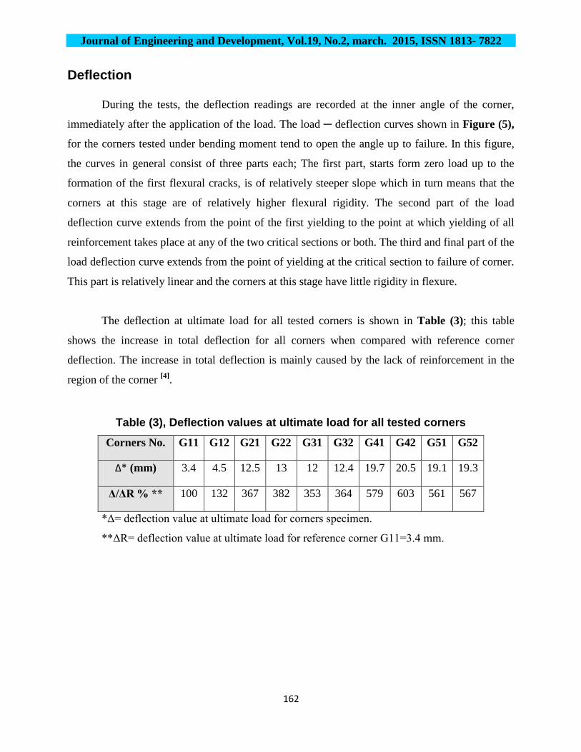
The deflection at ultimate load for all tested corners is shown in Table (3); this table
shows the increase in total deflection for all corners when compared with reference corner
deflection. The increase in total deflection is mainly caused by the lack of reinforcement in the
region of the corner P
[4]P.
Table (3), Deflection values at ultimate load for all tested corners
Corners No. G11 G12 G21 G22 G31 G32 G41 G42 G51 G52
Δ* (mm) 3.4 4.5 12.5 13 12 12.4 19.7 20.5 19.1 19.3
Δ/ΔR % ** 100 132 367 382 353 364 579 603 561 567
*Δ= deflection value at ultimate load for corners specimen.
**ΔR= deflection value at ultimate load for reference corner G11=3.4 mm.

Journal of Engineering and Development, Vol.19, No.2, march. 2015, ISSN 1813- 7822
163
Figu
re (5
), Lo
ad D
efle
ctio
n cu
rve
for a
ll te
sted
cor
ners
Journal of Engineering and Development, Vol.19, No.2, march. 2015, ISSN 1813- 7822
164
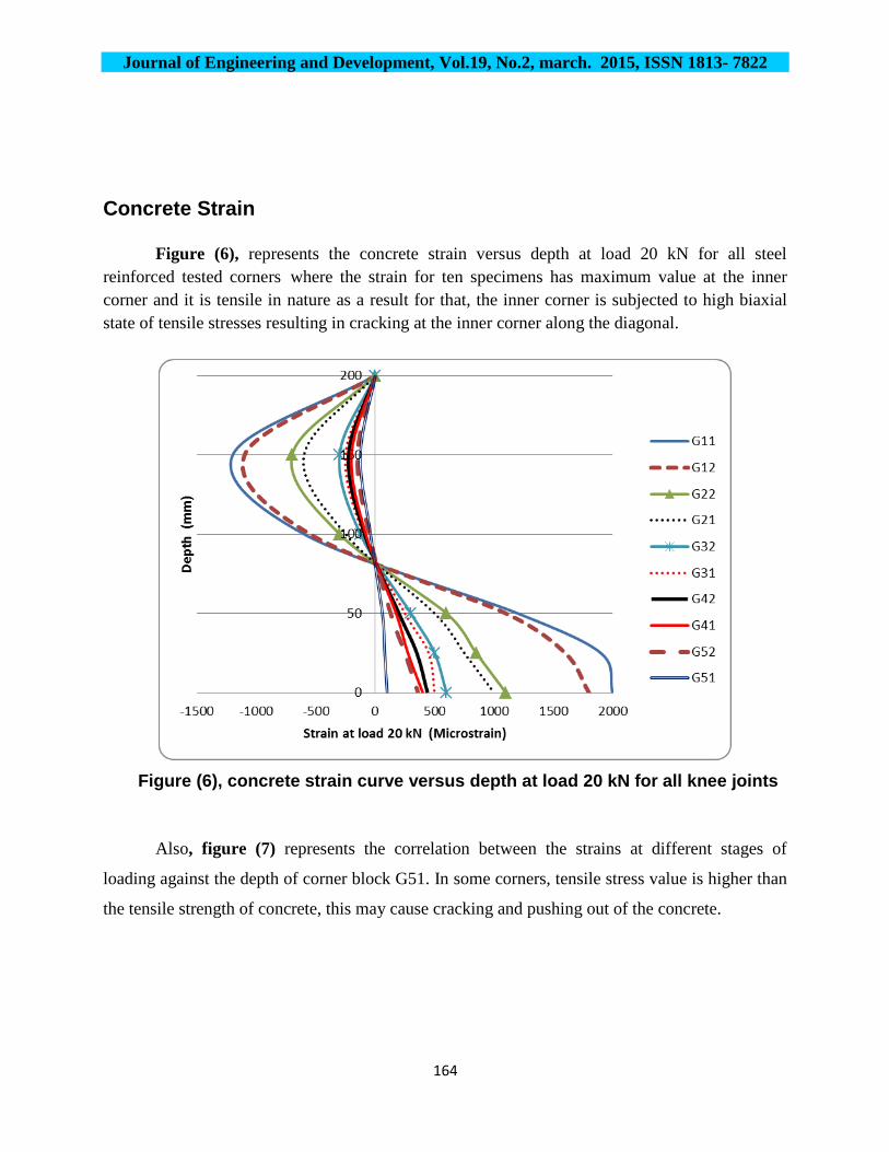
Concrete Strain
Figure (6), represents the concrete strain versus depth at load 20 kN for all steel reinforced tested corners where the strain for ten specimens has maximum value at the inner corner and it is tensile in nature as a result for that, the inner corner is subjected to high biaxial state of tensile stresses resulting in cracking at the inner corner along the diagonal.
Figure (6), concrete strain curve versus depth at load 20 kN for all knee joints
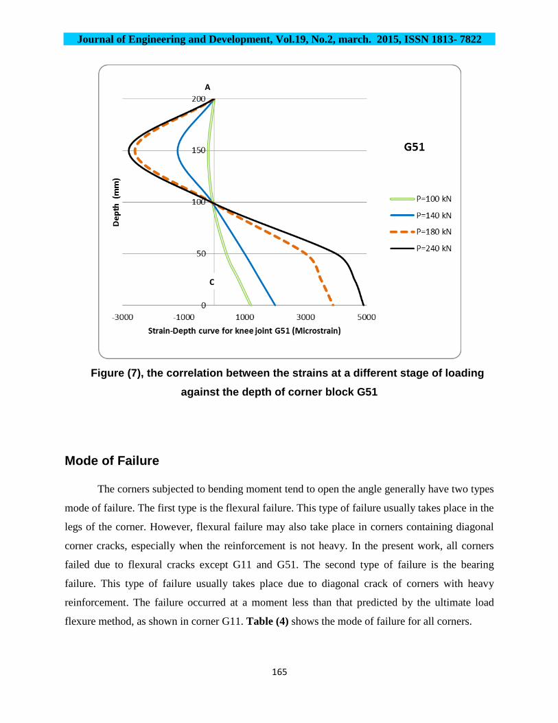
Also, figure (7) represents the correlation between the strains at different stages of
loading against the depth of corner block G51. In some corners, tensile stress value is higher than
the tensile strength of concrete, this may cause cracking and pushing out of the concrete.
Journal of Engineering and Development, Vol.19, No.2, march. 2015, ISSN 1813- 7822
165
Figure (7), the correlation between the strains at a different stage of loading
against the depth of corner block G51
Mode of Failure
The corners subjected to bending moment tend to open the angle generally have two types
mode of failure. The first type is the flexural failure. This type of failure usually takes place in the
legs of the corner. However, flexural failure may also take place in corners containing diagonal
corner cracks, especially when the reinforcement is not heavy. In the present work, all corners
failed due to flexural cracks except G11 and G51. The second type of failure is the bearing
failure. This type of failure usually takes place due to diagonal crack of corners with heavy
reinforcement. The failure occurred at a moment less than that predicted by the ultimate load
flexure method, as shown in corner G11. Table (4) shows the mode of failure for all corners.
A
C

Journal of Engineering and Development, Vol.19, No.2, march. 2015, ISSN 1813- 7822
166
Table (4), concrete knee joints mode of failure
Corn
ers
No.
G11 G12 G21 G22 G31 G32 G41 G42 G51 G52 G61 G62
Mod
e of
failu
re
at c
orne
r blo
ck
Bear
ing
Flex
ural
Flex
ural
Flex
ural
Flex
ural
Flex
ural
Flex
ural
Flex
ural
No
failu
re a
t co
rner
blo
ck
Flex
ural
Flex
ural
Flex
ural
Ultimate Strength of Corners
Ultimate moment is the maximum moment which could be carried out by the tested
corners. It is evident that the theoretical moment results of the steel reinforced NSC and MRPC
specimens varies between (9.82 and 10.7) kN.m; also the experimentally results of the ultimate
moment varies between (6.8 and 29.7) kN.m. The experimental moment results for all steel
reinforced NSC and MRPC knee joints are greater than theoretical (predicted) moment except
NSC knee joint G11 as shown in the Figure (8). This means that G11 fail before reach the
theoretical design strength. The ultimate moment increased by the presence and/or increment of
steel fiber content when the other parameters fixed. This is due to the fact that steel fibers act as
micro-reinforcement and crack arrester similar to flexural steel reinforced in conventional
reinforced concrete. After cracking, steel fibers seem to be capable to bear further tensile loads
until they are pulled out. For steel reinforced MRPC corners the addition of silica fume increases
the ultimate moment when the other parameters fixed. That could be attributed to the matrix
densification, which means: The presence of silica fume in the concrete mixes cause a reduction
in the volume of the pores. It basically acts as filler due to its fineness. Hence mechanical
properties are improved because of the enhancement of the bond strength. For MRPC, the
ultimate moment increased by the increase of fine aggregate proportions when other parameters
fixed, which means the increase of fine sand percentage with respect to fine gravel, due to the

Journal of Engineering and Development, Vol.19, No.2, march. 2015, ISSN 1813- 7822
167
bond strength between paste and steel reinforced, bond between past and steel fiber and the bond
between the paste and the aggregate.
Figure (8), Theoretical and experimental results of moment
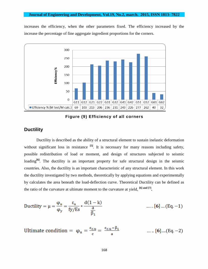
Corners Efficiency
The efficiency of a corner is defined as a ratio of the strength of the corner from a test to
the theoretical strength of the corner P
[1]P. The results show that the efficiency of corners vary
between (G11 and G51) by (69 to 277)% respectively, where all the corners are efficient except
the NSC reference corner G11 was deficient and would be unsafe in design, as shown in the
Figure (9). The normal strength concrete could not bear the applied moment; therefore enhance
the concrete properties using steel fiber with MRPC will improve the strength. In this case there
is no need for shear steel or steel reinforcement with complicated details in the corner block. The
randomly oriented steel fibers and the ability of steel fibers to arrest cracking widened process
cause an increase in the tensile load capacity beyond the first cracking, and that lead to increase
the efficiency. For steel reinforced MRPC knee joint specimens, the addition of silica fume
Journal of Engineering and Development, Vol.19, No.2, march. 2015, ISSN 1813- 7822
168
increases the efficiency, when the other parameters fixed. The efficiency increased by the
increase the percentage of fine aggregate ingredient proportions for the corners.
Figure (9) Efficiency of all corners
Ductility
Ductility is described as the ability of a structural element to sustain inelastic deformation
without significant loss in resistance P
[5]P. It is necessary for many reasons including safety,
possible redistribution of load or moment, and design of structures subjected to seismic
loadingP
[6]P. The ductility is an important property for safe structural design in the seismic
countries. Also, the ductility is an important characteristic of any structural element. In this work
the ductility investigated by two methods, theoretically by applying equations and experimentally
by calculates the area beneath the load-deflection curve. Theoretical Ductility can be defined as
the ratio of the curvature at ultimate moment to the curvature at yield, P
[6] and [7]P.
….(Eq 2)

Journal of Engineering and Development, Vol.19, No.2, march. 2015, ISSN 1813- 7822
169
….(Eq.-3)

Journal of Engineering and Development, Vol.19, No.2, march. 2015, ISSN 1813- 7822
170
The theoretical ductility value varies between (G11 and G51) by ductility value (3.11 and
15.24) respectively, and the experimental ductility index value varies between (G11 and G42) by
the ductility value (1.29 and 32.92) respectively. It is obvious that all the experimental ductility
values results of the steel reinforced MRPC knee joints are greater than the values of theoretical
ductility except G31. Also, the values of the theoretical ductility not proportioned with the values
of the experimental ductility index in the same ascending sort, as shown in the Figure (10).
Figure (10), comparison between theoretical and experimental Ductility
CONCLUSIONS
The following conclusions are drawn only from the twelve corners studied in this
investigation:
1- The knee joint G51 present the goal of this study because no cracks appear at corner block. The
efficiency of 277% due to enhancing the properties of concrete therefore no need for much
reinforcement at corner block. Also, G51 was the most influential corner which reveals the
maximum values of constituent properties and maximum values of structural properties except
the ductility. In contrast, the second descending most influential corner sorted after specimen G51
was the knee joint G31which represents reasonable efficiency 236%. The point of interest is,

Journal of Engineering and Development, Vol.19, No.2, march. 2015, ISSN 1813- 7822
171
increasing the steel fiber in MRPC with high content of silica fume will not improve the
properties as much as expected.
2- The corner G42 gained the maximum value of experimental ductility index (32.92). Therefore,
G42 considered the sufficient specimen for seismic and earthquake regions than the other knee
joints. In contrast, the corner G31 possessed the minimum ductility index (13.81) than the other
corners.
3- The use of steel fibers does not generally lead to an increase in compressive strength. But the
results showed that for all corners the compressive strength is only slightly increase by the
addition of steel fibers.
4- Increase steel fiber content for NSC and MRPC corners will increase the cracking moment,
ultimate moment, efficiency and experimental ductility. In contrast increase the steel fiber will
decrease the strain.
5- The increase of silica fume content in MRPC corners will increase the cracking moment,
ultimate moment and efficiency. In contrast, increase silica fume will decrease the strain,
experimental ductility and the deflection at the ultimate load.
6- The increase the fine aggregate proportions (fine sand/fine gravel) for the MRPC corners will
increase the cracking moment, ultimate moment and efficiency, while this will decrease the
strain, experimental ductility and the deflection at the ultimate load.
7- Silica fume and steel fiber were the most effected parameters on efficiency and ultimate
moment.
8- Steel fiber was the most effected parameter on the experimental ductility and deflection at the
ultimate load.
9- The structural properties of MRPC influenced by steel fiber and silica fume more than the
percentage of (fine sand/fine gravel).

Journal of Engineering and Development, Vol.19, No.2, march. 2015, ISSN 1813- 7822
172
REFERENCE 1- Mayfield B., Kong F. K. and Bennison A., "Strength and stiffness of lightweight concrete
corners", ACI Journal, Vol.69, No.38, July 1972, pp. 420-427.
2- Nilsson, I.H.E., "Reinforced Concrete Corners and Joints Subjected to Bending
Moment", National Swedish Building Research, Sweden, 1973, P.P. 244.
3- Nilsson I.H.E. and Losberg A.,"Reinforced concrete corners and joints subjected to
bending moment" Proceeding ASCE, Vol.102, No.6, 1976, pp.1229-1254.
4- Nilson, A.H., Darwin D. and Dolan CH. W. " Design of Concrete Structures" Thirteenth
Edition, The MacGraw-Hill Edition, 2004, 366p.
5- Naaman A.E., Harajli M.H., and Wight J.K. (1986). Analysis of ductility in partially
prestressed concrete flexural members. PCI Journal, 31:3, 64-87.
6- Park R. and Paulay T., "Reinforced Concrete Structures", John Wiley and Sons, 1975,
pp.195-761.
7- Oral Buyukozturk, “Mechanics and design of concrete structures”, Massachusetts
institute of technology, spring 2004,outline 6 ductility and deflections, pp. 1-9.