beer jhonsto cap 9
DESCRIPTION
Resolução liro beer jhonston cap 9TRANSCRIPT

PROBLEM 2.1
Two forces are applied to an eye bolt fastened to a beam. Determine graphically the magnitude and direction of their resultant using (a) the parallelogram law, (b) the triangle rule.
SOLUTION
(a)
(b)
We measure: 8.4 kNR =
19α = °
8.4 kN=R 19°
1
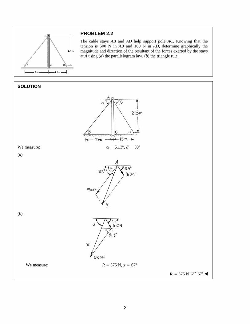
PROBLEM 2.2
The cable stays AB and AD help support pole AC. Knowing that the tension is 500 N in AB and 160 N in AD, determine graphically the magnitude and direction of the resultant of the forces exerted by the stays at A using (a) the parallelogram law, (b) the triangle rule.
SOLUTION
We measure: 51.3 , 59α β= ° = °
(a)
(b)
We measure: 575 N, 67α= = °R
575 N=R 67°
2

PROBLEM 2.3
Two forces P and Q are applied as shown at point A of a hook support. Knowing that P = 15 lb and Q = 25 lb, determine graphically the magnitude and direction of their resultant using (a) the parallelogram law, (b) the triangle rule.
SOLUTION
(a)
(b)
We measure: 37 lb, 76α= = °R
37 lb=R 76°
3

PROBLEM 2.4
Two forces P and Q are applied as shown at point A of a hook support. Knowing that P = 45 lb and Q = 15 lb, determine graphically the magnitude and direction of their resultant using (a) the parallelogram law, (b) the triangle rule.
SOLUTION
(a)
(b)
We measure: 61.5 lb, 86.5α= = °R
61.5 lb=R 86.5°
4
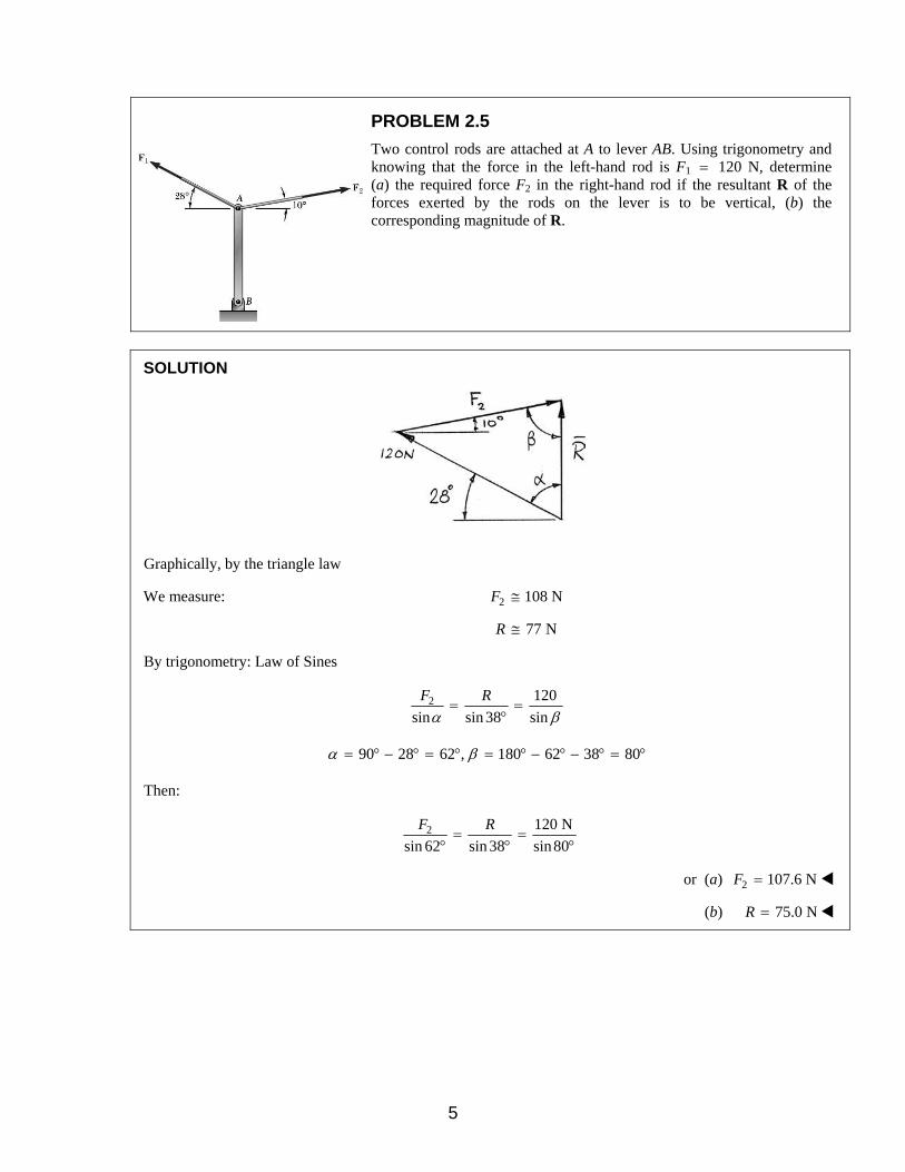
PROBLEM 2.5
Two control rods are attached at A to lever AB. Using trigonometry and knowing that the force in the left-hand rod is F1 = 120 N, determine (a) the required force F2 in the right-hand rod if the resultant R of the forces exerted by the rods on the lever is to be vertical, (b) the corresponding magnitude of R.
SOLUTION
Graphically, by the triangle law
We measure: 2 108 NF ≅
77 NR ≅
By trigonometry: Law of Sines
2 120
sin sin 38 sin
F R
α β= =
°
90 28 62 , 180 62 38 80α β= ° − ° = ° = ° − ° − ° = °
Then:
2 120 N
sin 62 sin 38 sin80
F R= =
° ° °
or (a) 2 107.6 NF =
(b) 75.0 NR =
5

PROBLEM 2.6
Two control rods are attached at A to lever AB. Using trigonometry and knowing that the force in the right-hand rod is F2 = 80 N, determine (a) the required force F1 in the left-hand rod if the resultant R of the forces exerted by the rods on the lever is to be vertical, (b) the corresponding magnitude of R.
SOLUTION
Using the Law of Sines
1 80
sin sin 38 sin
F R
α β= =
°
90 10 80 , 180 80 38 62α β= ° − ° = ° = ° − ° − ° = °
Then:
1 80 N
sin80 sin 38 sin 62
F R= =
° ° °
or (a) 1 89.2 NF =
(b) 55.8 NR =
6

PROBLEM 2.7
The 50-lb force is to be resolved into components along lines -a a′ and - .b b′ (a) Using trigonometry, determine the angle α knowing that the
component along -a a′ is 35 lb. (b) What is the corresponding value of the component along - ?b b′
SOLUTION
Using the triangle rule and the Law of Sines
(a) sin sin 40
35 lb 50 lb
β °=
sin 0.44995β =
26.74β = °
Then: 40 180α β+ + ° = °
113.3α = °
(b) Using the Law of Sines:
50 lb
sin sin 40bbF
α′ =
°
71.5 lbbbF ′ =
7

PROBLEM 2.8
The 50-lb force is to be resolved into components along lines -a a′ and - .b b′ (a) Using trigonometry, determine the angle α knowing that the
component along -b b′ is 30 lb. (b) What is the corresponding value of the component along - ?a a′
SOLUTION
Using the triangle rule and the Law of Sines
(a) sin sin 40
30 lb 50 lb
α °=
sin 0.3857α =
22.7α = °
(b) 40 180α β+ + ° = °
117.31β = °
50 lb
sin sin 40aaF
β′ =
°
sin
50 lbsin 40
β′
= ° aaF
69.1 lbaaF ′ =
8

PROBLEM 2.9
To steady a sign as it is being lowered, two cables are attached to the sign at A. Using trigonometry and knowing that α = 25°, determine (a) the required magnitude of the force P if the resultant R of the two forces applied at A is to be vertical, (b) the corresponding magnitude of R.
SOLUTION
Using the triangle rule and the Law of Sines
Have: ( )180 35 25α = ° − ° + °
120= °
Then: 360 N
sin 35 sin120 sin 25
P R= =
° ° °
or (a) 489 NP =
(b) 738 NR =
9

PROBLEM 2.10
To steady a sign as it is being lowered, two cables are attached to the sign at A. Using trigonometry and knowing that the magnitude of P is 300 N, determine (a) the required angle α if the resultant R of the two forces applied at A is to be vertical, (b) the corresponding magnitude of R.
SOLUTION
Using the triangle rule and the Law of Sines
(a) Have: 360 N 300 N
sin sin 35α=
°
sin 0.68829α =
43.5α = °
(b) ( )180 35 43.5β = − ° + °
101.5= °
Then: 300 N
sin101.5 sin 35
R=
° °
or 513 NR =
10

PROBLEM 2.11
Two forces are applied as shown to a hook support. Using trigonometry and knowing that the magnitude of P is 14 lb, determine (a) the required angle α if the resultant R of the two forces applied to the support is to be horizontal, (b) the corresponding magnitude of R.
SOLUTION
Using the triangle rule and the Law of Sines
(a) Have: 20 lb 14 lb
sin sin 30α=
°
sin 0.71428α =
45.6α = °
(b) ( )180 30 45.6β = ° − ° + °
104.4= °
Then: 14 lb
sin104.4 sin 30
R=
° °
27.1 lbR =
11

PROBLEM 2.12
For the hook support of Problem 2.3, using trigonometry and knowing that the magnitude of P is 25 lb, determine (a) the required magnitude of the force Q if the resultant R of the two forces applied at A is to be vertical, (b) the corresponding magnitude of R.
Problem 2.3: Two forces P and Q are applied as shown at point A of a hook support. Knowing that P = 15 lb and Q = 25 lb, determine graphically the magnitude and direction of their resultant using (a) the parallelogram law, (b) the triangle rule.
SOLUTION
Using the triangle rule and the Law of Sines
(a) Have: 25 lb
sin15 sin 30
Q=
° °
12.94 lbQ =
(b) ( )180 15 30β = ° − ° + °
135= °
Thus: 25 lb
sin135 sin 30
R=
° °
sin13525 lb 35.36 lb
sin 30R
° = = °
35.4 lbR =
12

PROBLEM 2.13
For the hook support of Problem 2.11, determine, using trigonometry, (a) the magnitude and direction of the smallest force P for which the resultant R of the two forces applied to the support is horizontal, (b) the corresponding magnitude of R.
Problem 2.11: Two forces are applied as shown to a hook support. Using trigonometry and knowing that the magnitude of P is 14 lb, determine (a) the required angle α if the resultant R of the two forces applied to the support is to be horizontal, (b) the corresponding magnitude of R.
SOLUTION
(a) The smallest force P will be perpendicular to R, that is, vertical
( )20 lb sin 30P = °
10 lb= 10 lb=P
(b) ( )20 lb cos30R = °
17.32 lb= 17.32 lbR =
13
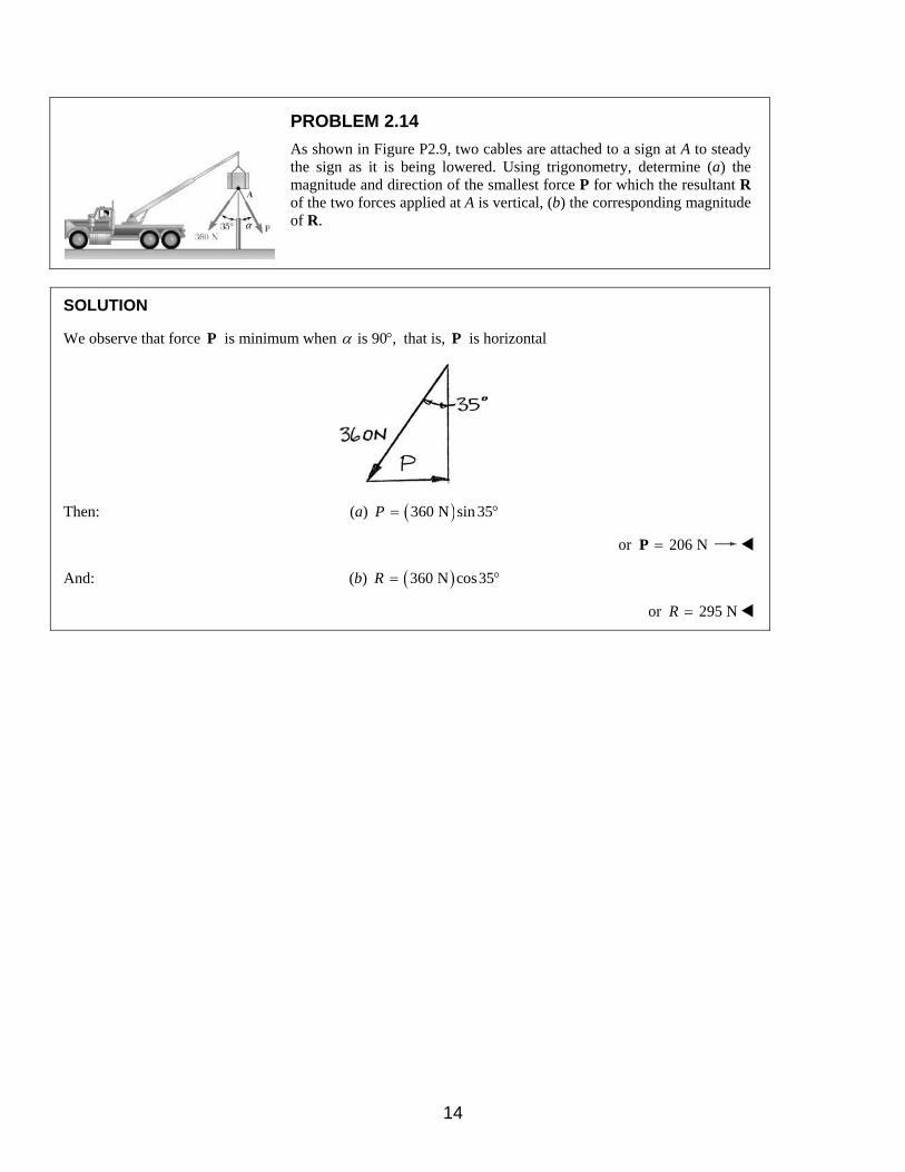
PROBLEM 2.14
As shown in Figure P2.9, two cables are attached to a sign at A to steady the sign as it is being lowered. Using trigonometry, determine (a) the magnitude and direction of the smallest force P for which the resultant R of the two forces applied at A is vertical, (b) the corresponding magnitude of R.
SOLUTION
We observe that force P is minimum when is 90 ,α ° that is, P is horizontal
Then: (a) ( )360 N sin 35P = °
or 206 N=P
And: (b) ( )360 N cos35R = °
or 295 NR =
14

PROBLEM 2.15
For the hook support of Problem 2.11, determine, using trigonometry, the magnitude and direction of the resultant of the two forces applied to the support knowing that P = 10 lb and α = 40°.
Problem 2.11: Two forces are applied as shown to a hook support. Using trigonometry and knowing that the magnitude of P is 14 lb, determine (a) the required angle α if the resultant R of the two forces applied to the support is to be horizontal, (b) the corresponding magnitude of R.
SOLUTION
Using the force triangle and the Law of Cosines
( ) ( ) ( )( )2 22 10 lb 20 lb 2 10 lb 20 lb cos110R = + − °
( ) 2100 400 400 0.342 lb = + − −
2636.8 lb=
25.23 lbR =
Using now the Law of Sines
10 lb 25.23 lb
sin sin110β=
°
10 lbsin sin110
25.23 lbβ = °
0.3724=
So: 21.87β = °
Angle of inclination of R, φ is then such that:
30φ β+ = °
8.13φ = °
Hence: 25.2 lb=R 8.13°
15
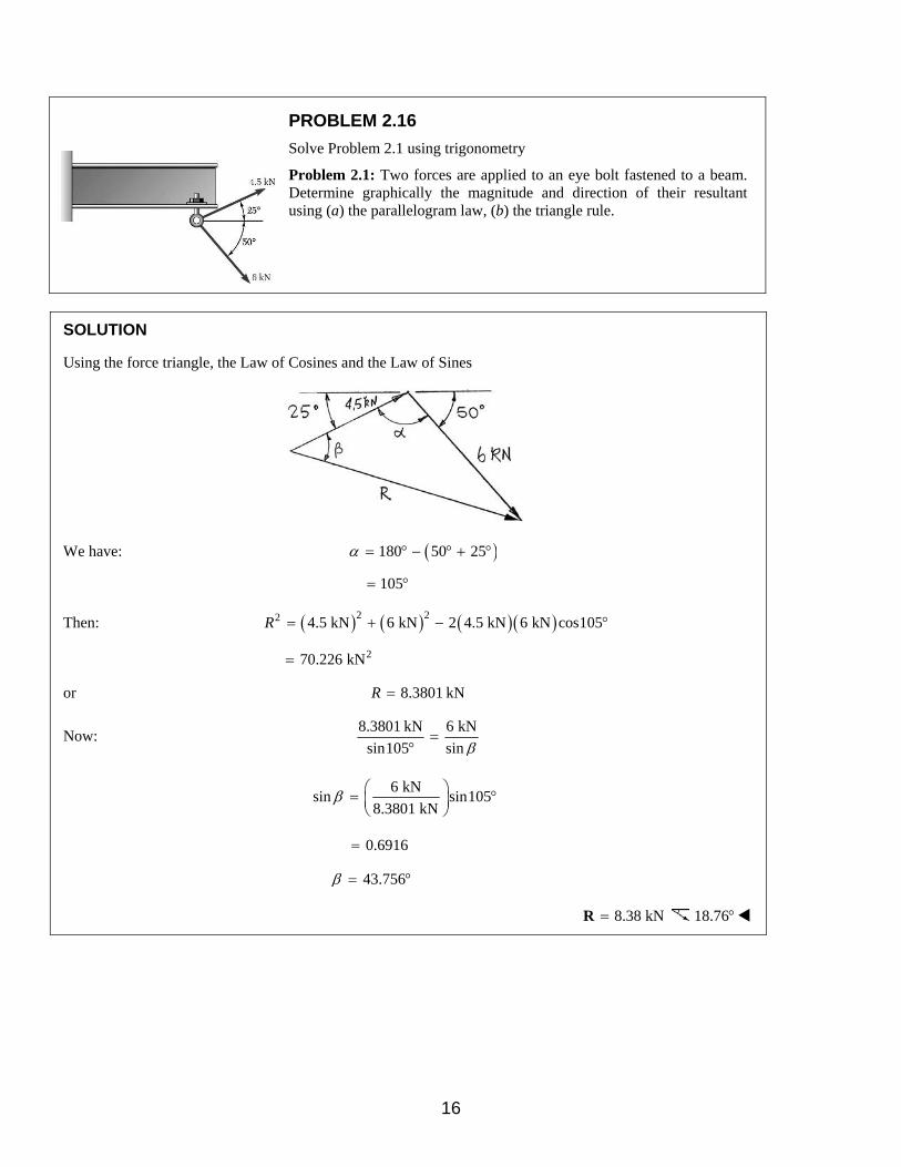
PROBLEM 2.16
Solve Problem 2.1 using trigonometry
Problem 2.1: Two forces are applied to an eye bolt fastened to a beam. Determine graphically the magnitude and direction of their resultant using (a) the parallelogram law, (b) the triangle rule.
SOLUTION
Using the force triangle, the Law of Cosines and the Law of Sines
We have: ( )180 50 25α = ° − ° + °
105= °
Then: ( ) ( ) ( )( )2 22 4.5 kN 6 kN 2 4.5 kN 6 kN cos105R = + − °
270.226 kN=
or 8.3801 kNR =
Now: 8.3801 kN 6 kN
sin105 sin β=
°
6 kNsin sin105
8.3801 kNβ = °
0.6916=
43.756β = °
8.38 kN=R 18.76°
16

PROBLEM 2.17
Solve Problem 2.2 using trigonometry
Problem 2.2: The cable stays AB and AD help support pole AC. Knowing that the tension is 500 N in AB and 160 N in AD, determine graphically the magnitude and direction of the resultant of the forces exerted by the stays at A using (a) the parallelogram law, (b) the triangle rule.
SOLUTION
From the geometry of the problem:
1 2tan 38.66
2.5α −= = °
1 1.5tan 30.96
2.5β −= = °
Now: ( )180 38.66 30.96 110.38θ = ° − + ° =
And, using the Law of Cosines:
( ) ( ) ( )( )2 22 500 N 160 N 2 500 N 160 N cos110.38R = + − °
2331319 N=
575.6 NR =
Using the Law of Sines:
160 N 575.6 N
sin sin110.38γ=
°
160 Nsin sin110.38
575.6 Nγ = °
0.2606=
15.1γ = °
( )90 66.44φ α γ= ° − + = °
576 N=R 66.4°
17

PROBLEM 2.18
Solve Problem 2.3 using trigonometry
Problem 2.3: Two forces P and Q are applied as shown at point A of a hook support. Knowing that P = 15 lb and Q = 25 lb, determine graphically the magnitude and direction of their resultant using (a) the parallelogram law, (b) the triangle rule.
SOLUTION
Using the force triangle and the Laws of Cosines and Sines
We have:
( )180 15 30γ = ° − ° + °
135= °
Then: ( ) ( ) ( )( )2 22 15 lb 25 lb 2 15 lb 25 lb cos135R = + − °
21380.3 lb=
or 37.15 lbR =
and
25 lb 37.15 lb
sin sin135β=
°
25 lbsin sin135
37.15 lbβ = °
0.4758=
28.41β = °
Then: 75 180α β+ + ° = °
76.59α = °
37.2 lb=R 76.6°
18

PROBLEM 2.19
Two structural members A and B are bolted to a bracket as shown. Knowing that both members are in compression and that the force is 30 kN in member A and 20 kN in member B, determine, using trigonometry, the magnitude and direction of the resultant of the forces applied to the bracket by members A and B.
SOLUTION
Using the force triangle and the Laws of Cosines and Sines
We have: ( )180 45 25 110γ = ° − ° + ° = °
Then: ( ) ( ) ( )( )2 22 30 kN 20 kN 2 30 kN 20 kN cos110R = + − °
21710.4 kN=
41.357 kNR =
and
20 kN 41.357 kN
sin sin110α=
°
20 kNsin sin110
41.357 kNα = °
0.4544=
27.028α = °
Hence: 45 72.028φ α= + ° = °
41.4 kN=R 72.0°
19
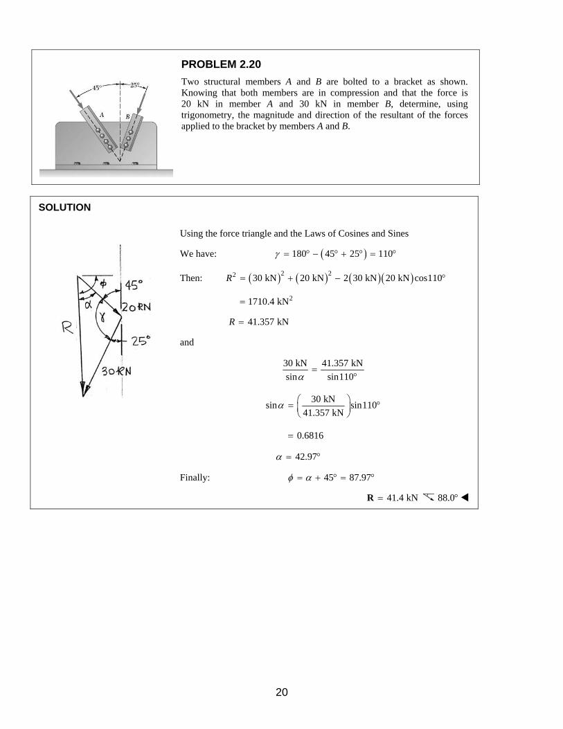
PROBLEM 2.20
Two structural members A and B are bolted to a bracket as shown. Knowing that both members are in compression and that the force is 20 kN in member A and 30 kN in member B, determine, using trigonometry, the magnitude and direction of the resultant of the forces applied to the bracket by members A and B.
SOLUTION
Using the force triangle and the Laws of Cosines and Sines
We have: ( )180 45 25 110γ = ° − ° + ° = °
Then: ( ) ( ) ( )( )2 22 30 kN 20 kN 2 30 kN 20 kN cos110R = + − °
21710.4 kN=
41.357 kNR =
and
30 kN 41.357 kN
sin sin110α=
°
30 kNsin sin110
41.357 kNα = °
0.6816=
42.97α = °
Finally: 45 87.97φ α= + ° = °
41.4 kN=R 88.0°
20

PROBLEM 2.21
Determine the x and y components of each of the forces shown.
SOLUTION
20 kN Force:
( )20 kN cos 40 ,xF = + ° 15.32 kNxF =
( )20 kN sin 40 ,yF = + ° 12.86 kNyF =
30 kN Force:
( )30 kN cos70 ,xF = − ° 10.26 kNxF = −
( )30 kN sin 70 ,yF = + ° 28.2 kNyF =
42 kN Force:
( )42 kN cos 20 ,xF = − ° 39.5 kNxF = −
( )42 kN sin 20 ,yF = + ° 14.36 kNyF =
21
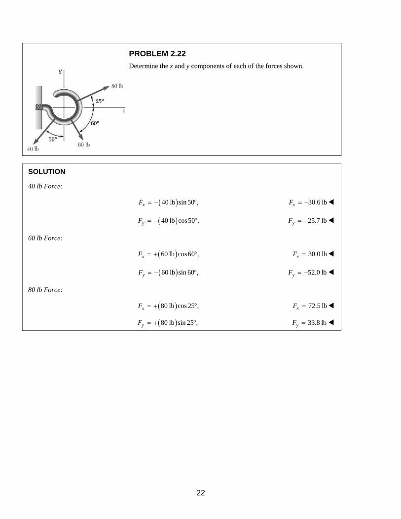
PROBLEM 2.22
Determine the x and y components of each of the forces shown.
SOLUTION
40 lb Force:
( )40 lb sin 50 ,xF = − ° 30.6 lbxF = −
( )40 lb cos50 ,yF = − ° 25.7 lbyF = −
60 lb Force:
( )60 lb cos60 ,xF = + ° 30.0 lbxF =
( )60 lb sin 60 ,yF = − ° 52.0 lbyF = −
80 lb Force:
( )80 lb cos 25 ,xF = + ° 72.5 lbxF =
( )80 lb sin 25 ,yF = + ° 33.8 lbyF =
22

PROBLEM 2.23
Determine the x and y components of each of the forces shown.
SOLUTION
We compute the following distances:
( ) ( )
( ) ( )
( ) ( )
2 2
2 2
2 2
48 90 102 in.
56 90 106 in.
80 60 100 in.
OA
OB
OC
= + =
= + =
= + =
Then:
204 lb Force:
( ) 48102 lb ,
102xF = − 48.0 lbxF = −
( ) 90102 lb ,
102yF = + 90.0 lbyF =
212 lb Force:
( ) 56212 lb ,
106xF = + 112.0 lbxF =
( ) 90212 lb ,
106yF = + 180.0 lbyF =
400 lb Force:
( ) 80400 lb ,
100xF = − 320 lbxF = −
( ) 60400 lb ,
100yF = − 240 lbyF = −
23

PROBLEM 2.24
Determine the x and y components of each of the forces shown.
SOLUTION
We compute the following distances:
( ) ( )2 270 240 250 mmOA = + =
( ) ( )2 2210 200 290 mmOB = + =
( ) ( )2 2120 225 255 mmOC = + =
500 N Force:
70
500 N250xF
= −
140.0 NxF = −
240
500 N250yF
= +
480 NyF =
435 N Force:
210
435 N290xF
= +
315 NxF =
200
435 N290yF
= +
300 NyF =
510 N Force:
120
510 N255xF
= +
240 NxF =
225
510 N255yF
= −
450 NyF = −
24
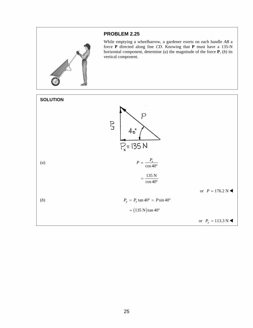
PROBLEM 2.25
While emptying a wheelbarrow, a gardener exerts on each handle AB a force P directed along line CD. Knowing that P must have a 135-N horizontal component, determine (a) the magnitude of the force P, (b) its vertical component.
SOLUTION
(a) cos 40
xPP =
°
135 N
cos 40=
°
or 176.2 NP =
(b) tan 40 sin 40y xP P P= ° = °
( )135 N tan 40= °
or 113.3 NyP =
25

PROBLEM 2.26
Member BD exerts on member ABC a force P directed along line BD. Knowing that P must have a 960-N vertical component, determine (a) the magnitude of the force P, (b) its horizontal component.
SOLUTION
(a) sin 35
yPP =
°
960 N
sin 35=
°
or 1674 NP =
(b) tan 35
yx
PP =
°
960 N
tan 35=
°
or 1371 NxP =
26

PROBLEM 2.27
Member CB of the vise shown exerts on block B a force P directed along line CB. Knowing that P must have a 260-lb horizontal component, determine (a) the magnitude of the force P, (b) its vertical component.
SOLUTION
We note:
CB exerts force P on B along CB, and the horizontal component of P is 260 lb.xP =
Then:
(a) sin 50xP P= °
sin 50
xPP =
°
260 lb
sin50=
°
339.4 lb= 339 lbP =
(b) tan 50x yP P= °
tan 50
xy
PP =
°
260 lb
tan 50=
°
218.2 lb= 218 lby =P
27

PROBLEM 2.28
Activator rod AB exerts on crank BCD a force P directed along line AB. Knowing that P must have a 25-lb component perpendicular to arm BC of the crank, determine (a) the magnitude of the force P, (b) its component along line BC.
SOLUTION
Using the x and y axes shown.
(a) 25 lbyP =
Then: sin 75
yPP =
°
25 lb
sin 75=
°
or 25.9 lbP =
(b) tan 75
yx
PP =
°
25 lb
tan 75=
°
or 6.70 lbxP =
28

PROBLEM 2.29
The guy wire BD exerts on the telephone pole AC a force P directed along BD. Knowing that P has a 450-N component along line AC, determine (a) the magnitude of the force P, (b) its component in a direction perpendicular to AC.
SOLUTION
Note that the force exerted by BD on the pole is directed along BD, and the component of P along AC is 450 N.
Then:
(a) 450 N
549.3 Ncos35
P = =°
549 NP =
(b) ( )450 N tan 35xP = °
315.1 N=
315 NxP =
29

PROBLEM 2.30
The guy wire BD exerts on the telephone pole AC a force P directed along BD. Knowing that P has a 200-N perpendicular to the pole AC, determine (a) the magnitude of the force P, (b) its component along line AC.
SOLUTION
(a) sin 38
xPP =
°
200 N
sin 38=
°
324.8 N= or 325 NP =
(b) tan 38
xy
PP =
°
200 N
tan 38=
°
255.98 N=
or 256 NyP =
30
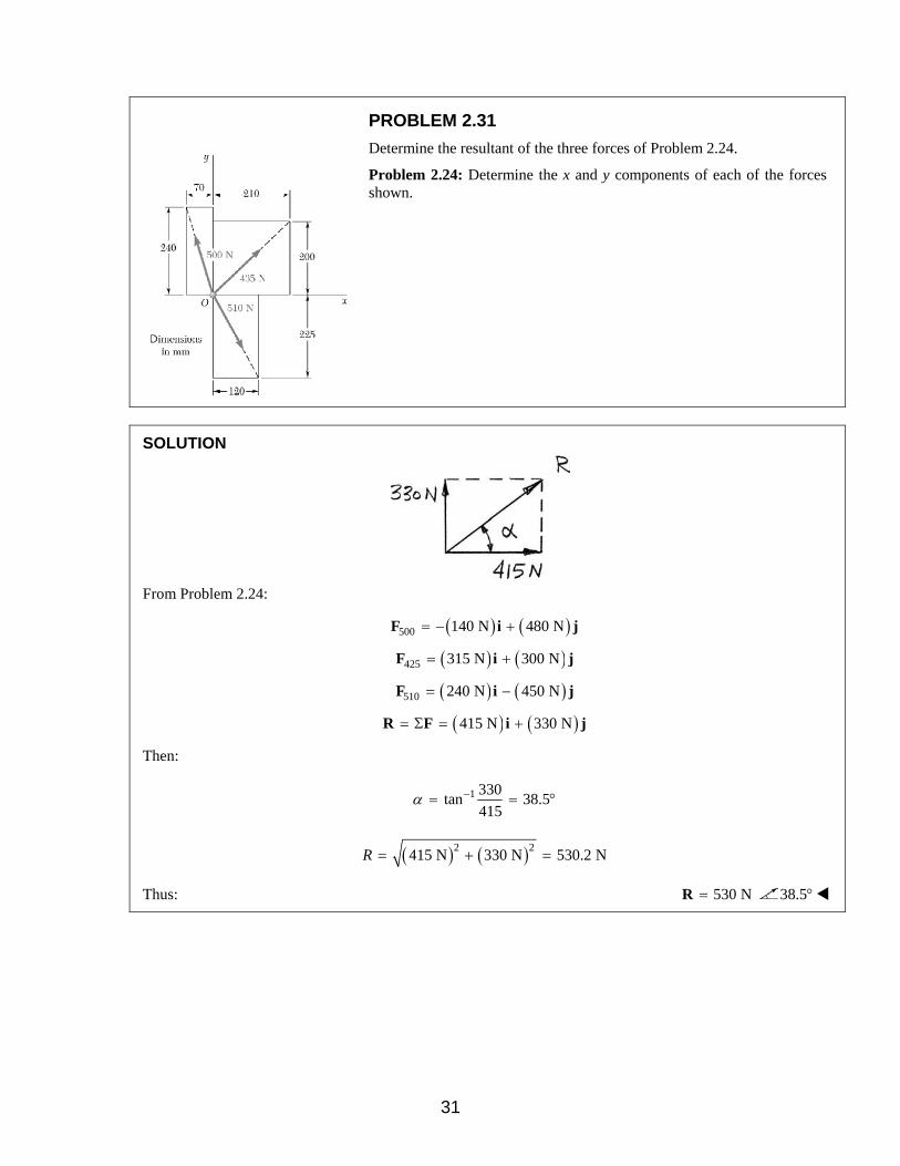
PROBLEM 2.31
Determine the resultant of the three forces of Problem 2.24.
Problem 2.24: Determine the x and y components of each of the forces shown.
SOLUTION
From Problem 2.24:
( ) ( )500 140 N 480 N= − +F i j
( ) ( )425 315 N 300 N= +F i j
( ) ( )510 240 N 450 N= −F i j
( ) ( )415 N 330 N= Σ = +R F i j
Then:
1 330tan 38.5
415α −= = °
( ) ( )2 2415 N 330 N 530.2 NR = + =
Thus: 530 N=R 38.5°
31
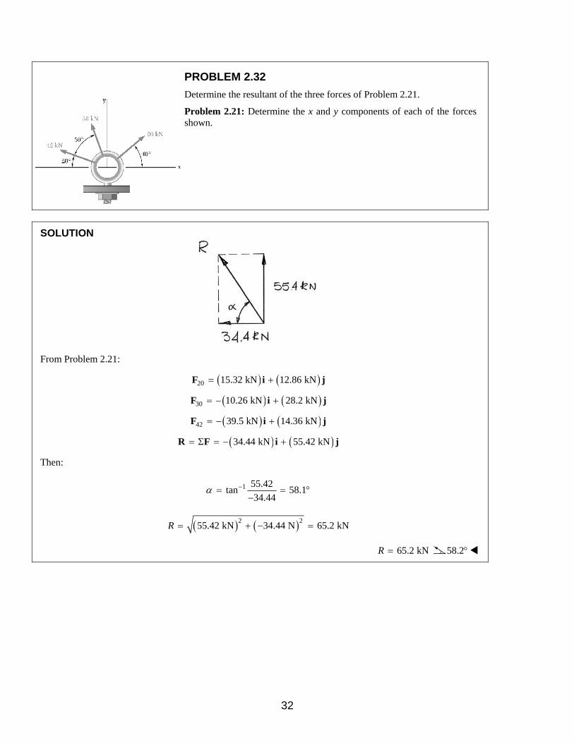
PROBLEM 2.32
Determine the resultant of the three forces of Problem 2.21.
Problem 2.21: Determine the x and y components of each of the forces shown.
SOLUTION
From Problem 2.21:
( ) ( )20 15.32 kN 12.86 kN= +F i j
( ) ( )30 10.26 kN 28.2 kN= − +F i j
( ) ( )42 39.5 kN 14.36 kN= − +F i j
( ) ( )34.44 kN 55.42 kN= Σ = − +R F i j
Then:
1 55.42tan 58.1
34.44α −= = °
−
( ) ( )2 255.42 kN 34.44 N 65.2 kNR = + − =
65.2 kNR = 58.2°
32

PROBLEM 2.33
Determine the resultant of the three forces of Problem 2.22.
Problem 2.22: Determine the x and y components of each of the forces shown.
SOLUTION
The components of the forces were determined in 2.23.
x yR R= +R i j
( ) ( )71.9 lb 43.86 lb= −i j
43.86tan
71.9α =
31.38α = °
( ) ( )2 271.9 lb 43.86 lbR = + −
84.23 lb=
84.2 lb=R 31.4°
Force comp. (lb)x comp. (lb)y
40 lb 30.6− 25.7−
60 lb 30 51.96−
80 lb 72.5 33.8
71.9xR = 43.86yR = −
33

PROBLEM 2.34
Determine the resultant of the three forces of Problem 2.23.
Problem 2.23: Determine the x and y components of each of the forces shown.
SOLUTION
The components of the forces were determined in Problem 2.23.
( ) ( )204 48.0 lb 90.0 lb= − +F i j
( ) ( )212 112.0 lb 180.0 lb= +F i j
( ) ( )400 320 lb 240 lb= − −F i j
Thus
x y= +R R R
( ) ( )256 lb 30.0 lb= − +R i j
Now:
30.0tan
256α =
1 30.0tan 6.68
256α −= = °
and
( ) ( )2 2256 lb 30.0 lbR = − +
257.75 lb=
258 lb=R 6.68°
34
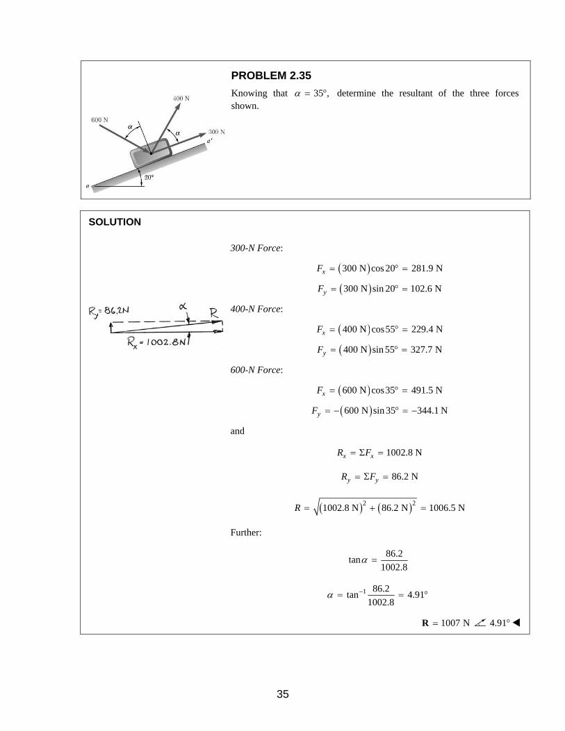
PROBLEM 2.35
Knowing that 35 ,α = ° determine the resultant of the three forces shown.
SOLUTION
300-N Force:
( )300 N cos 20 281.9 NxF = ° =
( )300 N sin 20 102.6 NyF = ° =
400-N Force:
( )400 N cos55 229.4 NxF = ° =
( )400 N sin 55 327.7 NyF = ° =
600-N Force:
( )600 N cos35 491.5 NxF = ° =
( )600 N sin 35 344.1 NyF = − ° = −
and
1002.8 Nx xR F= Σ =
86.2 Ny yR F= Σ =
( ) ( )2 21002.8 N 86.2 N 1006.5 NR = + =
Further:
86.2tan
1002.8α =
1 86.2tan 4.91
1002.8α −= = °
1007 N=R 4.91°
35
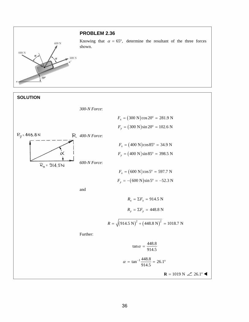
PROBLEM 2.36
Knowing that 65 ,α = ° determine the resultant of the three forces shown.
SOLUTION
300-N Force:
( )300 N cos 20 281.9 NxF = ° =
( )300 N sin 20 102.6 NyF = ° =
400-N Force:
( )400 N cos85 34.9 NxF = ° =
( )400 N sin85 398.5 NyF = ° =
600-N Force:
( )600 N cos5 597.7 NxF = ° =
( )600 N sin 5 52.3 NyF = − ° = −
and
914.5 Nx xR F= Σ =
448.8 Ny yR F= Σ =
( ) ( )2 2914.5 N 448.8 N 1018.7 NR = + =
Further:
448.8tan
914.5α =
1 448.8tan 26.1
914.5α −= = °
1019 N=R 26.1°
36

PROBLEM 2.37
Knowing that the tension in cable BC is 145 lb, determine the resultant of the three forces exerted at point B of beam AB.
SOLUTION
Cable BC Force:
( ) 84145 lb 105 lb
116xF = − = −
( ) 80145 lb 100 lb
116yF = =
100-lb Force:
( ) 3100 lb 60 lb
5xF = − = −
( ) 4100 lb 80 lb
5yF = − = −
156-lb Force:
( )12156 lb 144 lb
13xF = =
( ) 5156 lb 60 lb
13yF = − = −
and
21 lb, 40 lbx x y yR F R F= Σ = − = Σ = −
( ) ( )2 221 lb 40 lb 45.177 lbR = − + − =
Further:
40tan
21α =
1 40tan 62.3
21α −= = °
Thus: 45.2 lb=R 62.3°
37

PROBLEM 2.38
Knowing that 50 ,α = ° determine the resultant of the three forces shown.
SOLUTION
The resultant force R has the x- and y-components:
( ) ( ) ( )140 lb cos50 60 lb cos85 160 lb cos50x xR F= Σ = ° + ° − °
7.6264 lbxR = −
and
( ) ( ) ( )140 lb sin 50 60 lb sin85 160 lb sin 50y yR F= Σ = ° + ° + °
289.59 lbyR =
Further:
290tan
7.6α =
1 290tan 88.5
7.6α −= = °
Thus: 290 lb=R 88.5°
38

PROBLEM 2.39
Determine (a) the required value of α if the resultant of the three forces shown is to be vertical, (b) the corresponding magnitude of the resultant.
SOLUTION
For an arbitrary angle ,α we have:
( ) ( ) ( ) ( )140 lb cos 60 lb cos 35 160 lb cosx xR F α α α= Σ = + + ° −
(a) So, for R to be vertical:
( ) ( ) ( ) ( )140 lb cos 60 lb cos 35 160 lb cos 0x xR F α α α= Σ = + + ° − =
Expanding,
( )cos 3 cos cos35 sin sin 35 0α α α− + ° − ° =
Then:
13cos35
tansin 35
α° −
=°
or
1
1 3cos35tan 40.265
sin 35α − ° −
= = ° ° 40.3α = °
(b) Now:
( ) ( ) ( )140 lb sin 40.265 60 lb sin 75.265 160 lb sin 40.265y yR R F= = Σ = ° + ° + °
252 lbR R= =
39

PROBLEM 2.40
For the beam of Problem 2.37, determine (a) the required tension in cable BC if the resultant of the three forces exerted at point B is to be vertical, (b) the corresponding magnitude of the resultant.
Problem 2.37: Knowing that the tension in cable BC is 145 lb, determine the resultant of the three forces exerted at point B of beam AB.
SOLUTION
We have:
( ) ( )84 12 3156 lb 100 lb
116 13 5x x BCR F T= Σ = − + −
or 0.724 84 lbx BCR T= − +
and
( ) ( )80 5 4156 lb 100 lb
116 13 5y y BCR F T= Σ = − −
0.6897 140 lby BCR T= −
(a) So, for R to be vertical,
0.724 84 lb 0x BCR T= − + =
116.0 lbBCT =
(b) Using
116.0 lbBCT =
( )0.6897 116.0 lb 140 lb 60 lbyR R= = − = −
60.0 lbR R= =
40

PROBLEM 2.41
Boom AB is held in the position shown by three cables. Knowing that the tensions in cables AC and AD are 4 kN and 5.2 kN, respectively, determine (a) the tension in cable AE if the resultant of the tensions exerted at point A of the boom must be directed along AB, (b) the corresponding magnitude of the resultant.
SOLUTION
Choose x-axis along bar AB.
Then
(a) Require
( ) ( )0: 4 kN cos 25 5.2 kN sin 35 sin 65 0y y AER F T= Σ = ° + ° − ° =
or 7.2909 kNAET =
7.29 kNAET =
(b) xR F= Σ
( ) ( ) ( )4 kN sin 25 5.2 kN cos35 7.2909 kN cos65= − ° − ° − °
9.03 kN= −
9.03 kNR =
41

PROBLEM 2.42
For the block of Problems 2.35 and 2.36, determine (a) the required value of α of the resultant of the three forces shown is to be parallel to the incline, (b) the corresponding magnitude of the resultant.
Problem 2.35: Knowing that 35 ,α = ° determine the resultant of the three forces shown.
Problem 2.36: Knowing that 65 ,α = ° determine the resultant of the three forces shown.
SOLUTION
Selecting the x axis along ,aa′ we write
( ) ( )300 N 400 N cos 600 N sinx xR F α α= Σ = + + (1)
( ) ( )400 N sin 600 N cosy yR F α α= Σ = − (2)
(a) Setting 0yR = in Equation (2):
Thus 600
tan 1.5400
α = =
56.3α = °
(b) Substituting for α in Equation (1):
( ) ( )300 N 400 N cos56.3 600 N sin 56.3xR = + ° + °
1021.1 NxR =
1021 NxR R= =
42

PROBLEM 2.43
Two cables are tied together at C and are loaded as shown. Determine the tension (a) in cable AC, (b) in cable BC.
SOLUTION
Free-Body Diagram
From the geometry, we calculate the distances:
( ) ( )2 216 in. 12 in. 20 in.AC = + =
( ) ( )2 220 in. 21 in. 29 in.BC = + =
Then, from the Free Body Diagram of point C:
16 21
0: 020 29x AC BCF T TΣ = − + =
or 29 4
21 5BC ACT T= ×
and 12 20
0: 600 lb 020 29y AC BCF T TΣ = + − =
or 12 20 29 4
600 lb 020 29 21 5AC ACT T
+ × − =
Hence: 440.56 lbACT =
(a) 441 lbACT =
(b) 487 lbBCT =
43

PROBLEM 2.44
Knowing that 25 ,α = ° determine the tension (a) in cable AC, (b) in rope BC.
SOLUTION
Free-Body Diagram Force Triangle
Law of Sines:
5 kN
sin115 sin 5 sin 60AC BCT T
= =° ° °
(a) 5 kN
sin115 5.23 kNsin 60ACT = ° =
° 5.23 kNACT =
(b) 5 kN
sin 5 0.503 kNsin 60BCT = ° =
° 0.503 kNBCT =
44
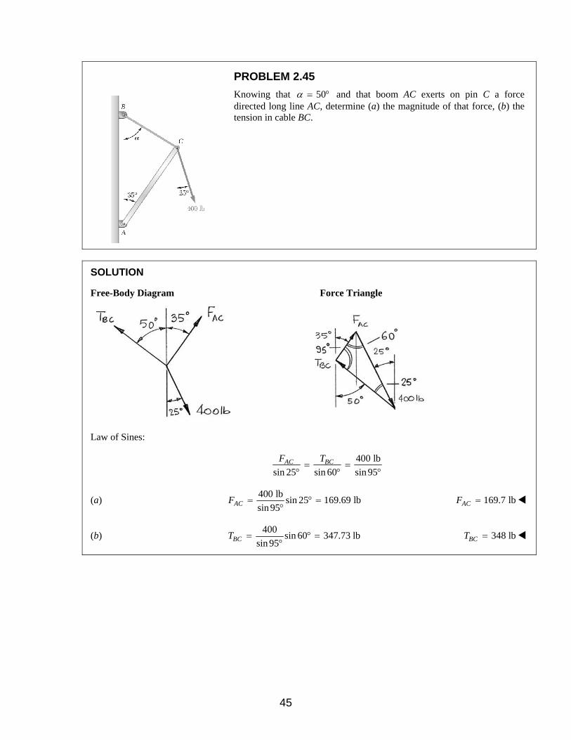
PROBLEM 2.45
Knowing that 50α = ° and that boom AC exerts on pin C a force directed long line AC, determine (a) the magnitude of that force, (b) the tension in cable BC.
SOLUTION
Free-Body Diagram Force Triangle
Law of Sines:
400 lb
sin 25 sin 60 sin 95AC BCF T
= =° ° °
(a) 400 lb
sin 25 169.69 lbsin 95ACF = ° =
° 169.7 lbACF =
(b) 400
sin 60 347.73 lbsin 95BCT = ° =
° 348 lbBCT =
45
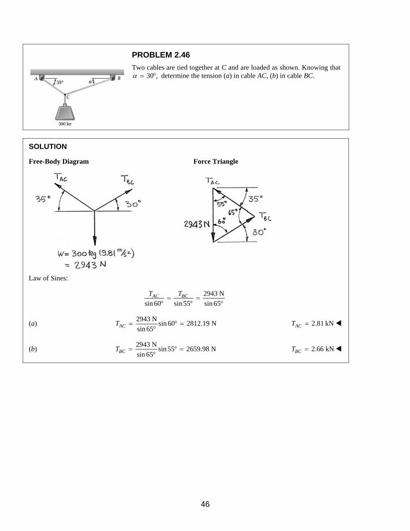
PROBLEM 2.46
Two cables are tied together at C and are loaded as shown. Knowing that 30 ,α = ° determine the tension (a) in cable AC, (b) in cable BC.
SOLUTION
Free-Body Diagram Force Triangle
Law of Sines:
2943 N
sin 60 sin 55 sin 65AC BCT T
= =° ° °
(a) 2943 N
sin 60 2812.19 Nsin 65ACT = ° =
° 2.81 kNACT =
(b) 2943 N
sin 55 2659.98 Nsin 65BCT = ° =
° 2.66 kNBCT =
46

PROBLEM 2.47
A chairlift has been stopped in the position shown. Knowing that each chair weighs 300 N and that the skier in chair E weighs 890 N, determine that weight of the skier in chair F.
SOLUTION
Free-Body Diagram Point B
Force Triangle
Free-Body Diagram Point C
Force Triangle
In the free-body diagram of point B, the geometry gives:
1 9.9tan 30.51
16.8ABθ −= = °
1 12tan 22.61
28.8BCθ −= = °
Thus, in the force triangle, by the Law of Sines:
1190 N
sin 59.49 sin 7.87BCT
=° °
7468.6 NBCT =
In the free-body diagram of point C (with W the sum of weights of chair and skier) the geometry gives:
1 1.32tan 10.39
7.2CDθ −= = °
Hence, in the force triangle, by the Law of Sines:
7468.6 N
sin12.23 sin100.39
W=
° °
1608.5 NW =
Finally, the skier weight 1608.5 N 300 N 1308.5 N= − =
skier weight 1309 N=
47

PROBLEM 2.48
A chairlift has been stopped in the position shown. Knowing that each chair weighs 300 N and that the skier in chair F weighs 800 N, determine the weight of the skier in chair E.
SOLUTION
Free-Body Diagram Point F
Force Triangle
Free-Body Diagram Point E
Force Triangle
In the free-body diagram of point F, the geometry gives:
1 12tan 22.62
28.8EFθ −= = °
1 1.32tan 10.39
7.2DFθ −= = °
Thus, in the force triangle, by the Law of Sines:
1100 N
sin100.39 sin12.23EFT
=° °
5107.5 NBCT =
In the free-body diagram of point E (with W the sum of weights of chair and skier) the geometry gives:
1 9.9tan 30.51
16.8AEθ −= = °
Hence, in the force triangle, by the Law of Sines:
5107.5 N
sin 7.89 sin 59.49
W=
° °
813.8 NW =
Finally, the skier weight 813.8 N 300 N 513.8 N= − =
skier weight 514 N=
48

PROBLEM 2.49
Four wooden members are joined with metal plate connectors and are in equilibrium under the action of the four fences shown. Knowing that FA = 510 lb and FB = 480 lb, determine the magnitudes of the other two forces.
SOLUTION
Free-Body Diagram
Resolving the forces into x and y components:
( ) ( )0: 510 lb sin15 480 lb cos15 0x CF FΣ = + ° − ° =
or 332 lbCF =
( ) ( )0: 510 lb cos15 480 lb sin15 0y DF FΣ = − ° + ° =
or 368 lbDF =
49

PROBLEM 2.50
Four wooden members are joined with metal plate connectors and are in equilibrium under the action of the four fences shown. Knowing that FA = 420 lb and FC = 540 lb, determine the magnitudes of the other two forces.
SOLUTION
Resolving the forces into x and y components:
( ) ( )0: cos15 540 lb 420 lb cos15 0 or 671.6 lbx B BF F FΣ = − ° + + ° = =
672 lbBF =
( ) ( )0: 420 lb cos15 671.6 lb sin15 0y DF FΣ = − ° + ° =
or 232 lbDF =
50

PROBLEM 2.51
Two forces P and Q are applied as shown to an aircraft connection. Knowing that the connection is in equilibrium and the P = 400 lb and Q = 520 lb, determine the magnitudes of the forces exerted on the rods A and B.
SOLUTION
Free-Body Diagram
Resolving the forces into x and y directions:
0A B= + + + =R P Q F F
Substituting components:
( ) ( ) ( )400 lb 520 lb cos55 520 lb sin 55 = − + ° − ° R j i j
( ) ( )cos55 sin 55 0B A AF F F+ − ° + ° =i i j
In the y-direction (one unknown force)
( )400 lb 520 lb sin 55 sin 55 0AF− − ° + ° =
Thus,
( )400 lb 520 lb sin 551008.3 lb
sin 55AF+ °
= =°
1008 lbAF =
In the x-direction:
( )520 lb cos55 cos55 0B AF F° + − ° =
Thus,
( )cos55 520 lb cos55B AF F= ° − °
( ) ( )1008.3 lb cos55 520 lb cos55= ° − °
280.08 lb=
280 lbBF =
51

PROBLEM 2.52
Two forces P and Q are applied as shown to an aircraft connection. Knowing that the connection is in equilibrium and that the magnitudes of the forces exerted on rods A and B are FA = 600 lb and FB = 320 lb, determine the magnitudes of P and Q.
SOLUTION
Free-Body Diagram
Resolving the forces into x and y directions:
0A B= + + + =R P Q F F
Substituting components:
( ) ( ) ( )320 lb 600 lb cos55 600 lb sin 55 = − ° + ° R i i j
( ) ( )cos55 sin 55 0P Q Q+ + ° − ° =i i j
In the x-direction (one unknown force)
( )320 lb 600 lb cos55 cos55 0Q− ° + ° =
Thus,
( )320 lb 600 lb cos5542.09 lb
cos55Q
− + °= =
°
42.1 lbQ =
In the y-direction:
( )600 lb sin 55 sin 55 0P Q° − − ° =
Thus,
( )600 lb sin 55 sin 55 457.01 lbP Q= ° − ° =
457 lbP =
52

PROBLEM 2.53
Two cables tied together at C are loaded as shown. Knowing that W = 840 N, determine the tension (a) in cable AC, (b) in cable BC.
SOLUTION
Free-Body Diagram
From geometry:
The sides of the triangle with hypotenuse CB are in the ratio 8:15:17.
The sides of the triangle with hypotenuse CA are in the ratio 3:4:5.
Thus:
( )3 15 150: 680 N 0
5 17 17x CA CBF T TΣ = − + − =
or
1 5
200 N5 17CA CBT T− + = (1)
and
( )4 8 80: 680 N 840 N 0
5 17 17y CA CBF T TΣ = + − − =
or
1 2
290 N5 17CA CBT T+ = (2)
Solving Equations (1) and (2) simultaneously:
(a) 750 NCAT =
(b) 1190 NCBT =
53
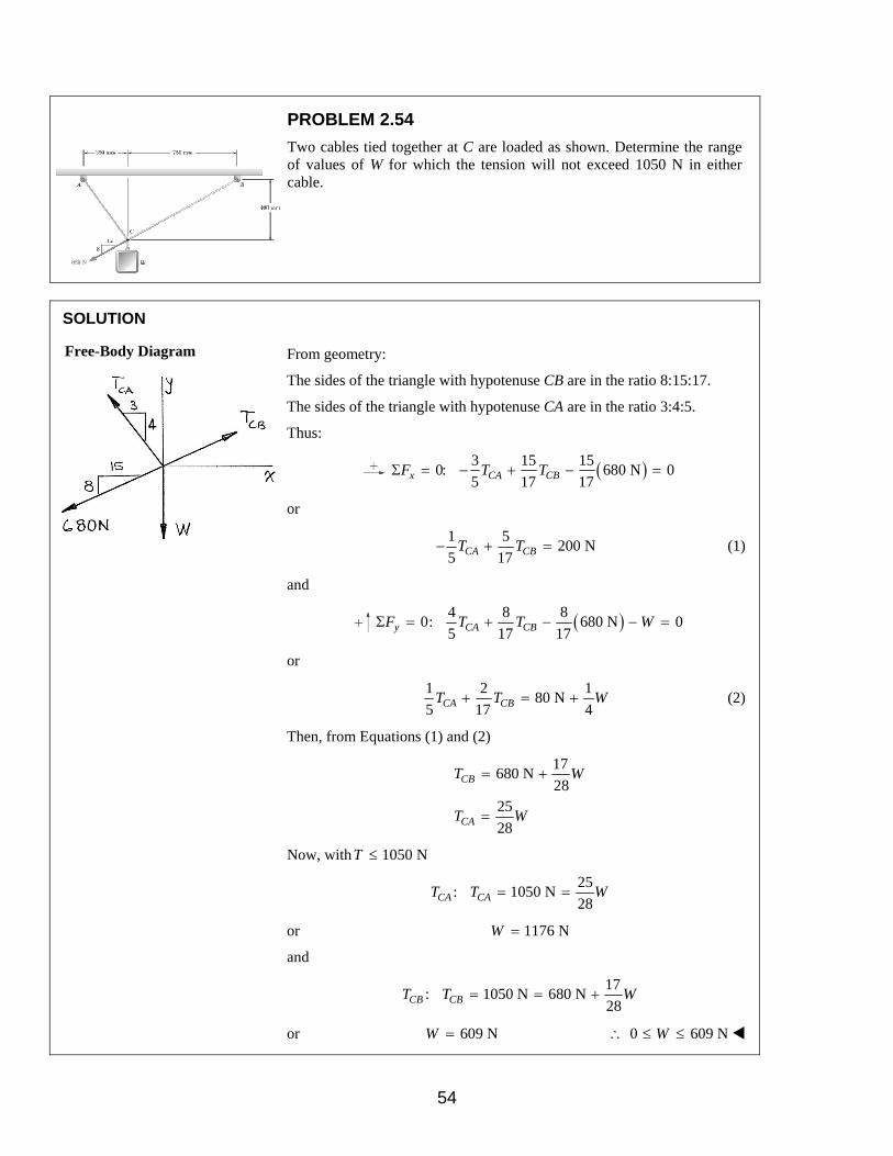
PROBLEM 2.54
Two cables tied together at C are loaded as shown. Determine the range of values of W for which the tension will not exceed 1050 N in either cable.
SOLUTION
Free-Body Diagram
From geometry:
The sides of the triangle with hypotenuse CB are in the ratio 8:15:17.
The sides of the triangle with hypotenuse CA are in the ratio 3:4:5.
Thus:
( )3 15 150: 680 N 0
5 17 17x CA CBF T TΣ = − + − =
or
1 5
200 N5 17CA CBT T− + = (1)
and
( )4 8 80: 680 N 0
5 17 17y CA CBF T T WΣ = + − − =
or
1 2 1
80 N5 17 4
+ = +CA CBT T W (2)
Then, from Equations (1) and (2)
17680 N
2825
28
CB
CA
T W
T W
= +
=
Now, with 1050 NT ≤
25: 1050 N
28CA CAT T W= =
or 1176 NW =
and
17: 1050 N 680 N
28CB CBT T W= = +
or 609 NW = 0 609 N∴ ≤ ≤W
54

PROBLEM 2.55
The cabin of an aerial tramway is suspended from a set of wheels that can roll freely on the support cable ACB and is being pulled at a constant speed by cable DE. Knowing that 40α = ° and β = 35°, that the combined weight of the cabin, its support system, and its passengers is 24.8 kN, and assuming the tension in cable DF to be negligible, determine the tension (a) in the support cable ACB, (b) in the traction cable DE.
SOLUTION
Note: In Problems 2.55 and 2.56 the cabin is considered as a particle. If considered as a rigid body (Chapter 4) it would be found that its center of gravity should be located to the left of the centerline for the line CD to be vertical.
Now
( )0: cos35 cos 40 cos 40 0x ACB DEF T TΣ = ° − ° − ° =
or
0.0531 0.766 0ACB DET T− = (1)
and
( )0: sin 40 sin 35 sin 40 24.8 kN 0y ACB DEF T TΣ = ° − ° + ° − =
or
0.0692 0.643 24.8 kNACB DET T+ = (2)
From (1)
14.426ACB DET T=
Then, from (2)
( )0.0692 14.426 0.643 24.8 kNDE DET T+ =
and
(b) 15.1 kNDET =
(a) 218 kNACBT =
55

PROBLEM 2.56
The cabin of an aerial tramway is suspended from a set of wheels that can roll freely on the support cable ACB and is being pulled at a constant speed by cable DE. Knowing that 42α = ° and β = 32°, that the tension in cable DE is 20 kN, and assuming the tension in cable DF to be negligible, determine (a) the combined weight of the cabin, its support system, and its passengers, (b) the tension in the support cable ACB.
SOLUTION
Free-Body Diagram
First, consider the sum of forces in the x-direction because there is only one unknown force:
( ) ( )0: cos32 cos 42 20 kN cos 42 0x ACBF TΣ = ° − ° − ° =
or
0.1049 14.863 kNACBT =
(b) 141.7 kNACBT =
Now
( ) ( )0: sin 42 sin 32 20 kN sin 42 0y ACBF T WΣ = ° − ° + ° − =
or
( )( ) ( )( )141.7 kN 0.1392 20 kN 0.6691 0W+ − =
(a) 33.1 kNW =
56

PROBLEM 2.57
A block of weight W is suspended from a 500-mm long cord and two springs of which the unstretched lengths are 450 mm. Knowing that the constants of the springs are kAB = 1500 N/m and kAD = 500 N/m, determine (a) the tension in the cord, (b) the weight of the block.
SOLUTION
Free-Body Diagram At A
First note from geometry:
The sides of the triangle with hypotenuse AD are in the ratio 8:15:17.
The sides of the triangle with hypotenuse AB are in the ratio 3:4:5.
The sides of the triangle with hypotenuse AC are in the ratio 7:24:25.
Then:
( )AB AB AB oF k L L= −
and
( ) ( )2 20.44 m 0.33 m 0.55 mABL = + =
So:
( )1500 N/m 0.55 m 0.45 mABF = −
150 N=
Similarly,
( )AD AD AD oF k L L= −
Then:
( ) ( )2 20.66 m 0.32 m 0.68 mADL = + =
( )1500 N/m 0.68 m 0.45 mADF = −
115 N=
(a)
( ) ( )4 7 150: 150 N 115 N 0
5 25 17x ACF TΣ = − + − =
or
66.18 NACT = 66.2 NACT =
57

PROBLEM 2.57 CONTINUED
(b) and
( ) ( ) ( )3 24 80: 150 N 66.18 N 115 N 0
5 25 17yF WΣ = + + − =
or 208 N=W
58

PROBLEM 2.58
A load of weight 400 N is suspended from a spring and two cords which are attached to blocks of weights 3W and W as shown. Knowing that the constant of the spring is 800 N/m, determine (a) the value of W, (b) the unstretched length of the spring.
SOLUTION
Free-Body Diagram At A
First note from geometry:
The sides of the triangle with hypotenuse AD are in the ratio 12:35:37.
The sides of the triangle with hypotenuse AC are in the ratio 3:4:5.
The sides of the triangle with hypotenuse AB are also in the ratio 12:35:37.
Then:
( ) ( )4 35 120: 3 0
5 37 37x sF W W FΣ = − + + =
or
4.4833sF W=
and
( ) ( )3 12 350: 3 400 N 0
5 37 37y sF W W FΣ = + + − =
Then:
( ) ( ) ( )3 12 353 4.4833 400 N 0
5 37 37W W W+ + − =
or
62.841 NW =
and
281.74 NsF =
or
(a) 62.8 NW =
59

PROBLEM 2.58 CONTINUED
(b) Have spring force
( )s AB oF k L L= −
Where
( )AB AB AB oF k L L= −
and
( ) ( )2 20.360 m 1.050 m 1.110 mABL = + =
So:
( )0281.74 N 800 N/m 1.110 mL= −
or 0 758 mmL =
60

PROBLEM 2.59
For the cables and loading of Problem 2.46, determine (a) the value of α for which the tension in cable BC is as small as possible, (b) the corresponding value of the tension.
SOLUTION
The smallest BCT is when BCT is perpendicular to the direction of ACT
Free-Body Diagram At C Force Triangle
(a) 55.0α = °
(b) ( )2943 N sin 55BCT = °
2410.8 N=
2.41 kNBCT =
61
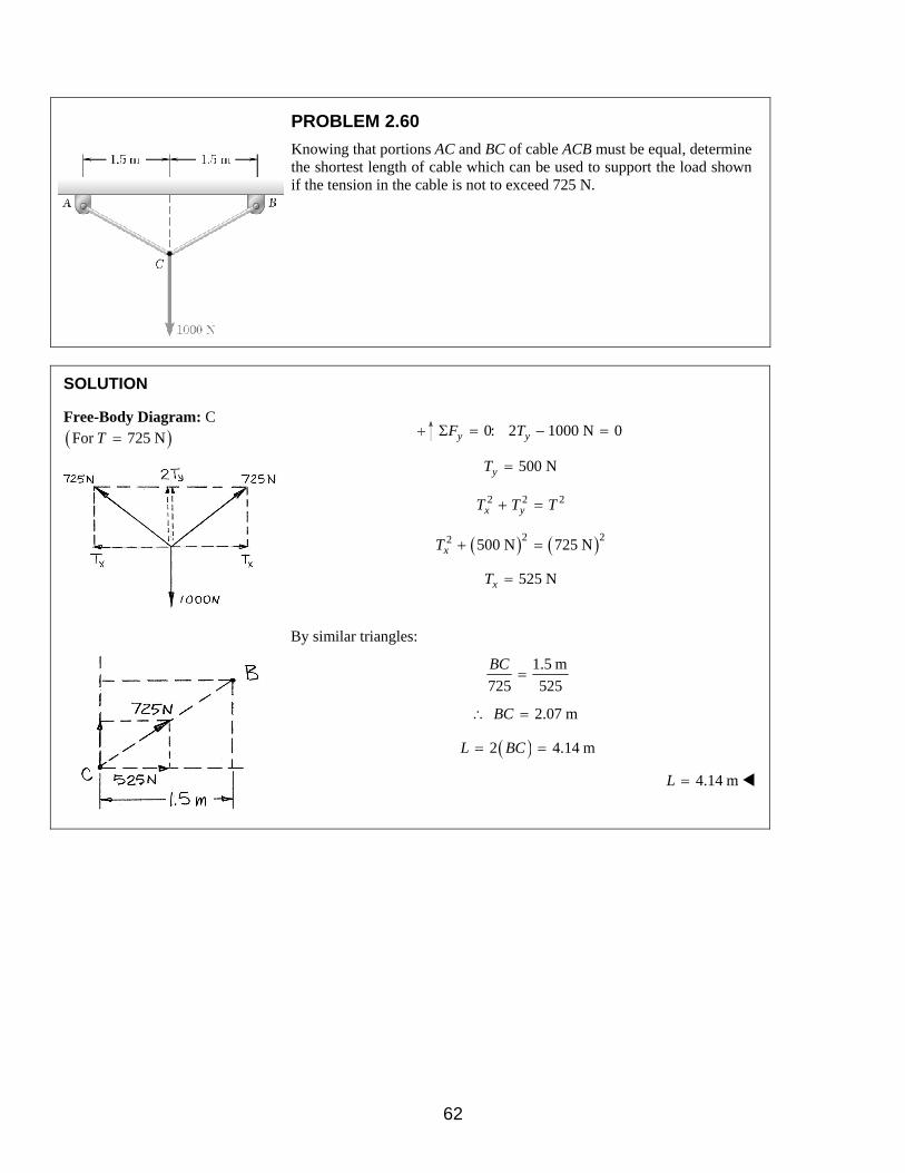
PROBLEM 2.60
Knowing that portions AC and BC of cable ACB must be equal, determine the shortest length of cable which can be used to support the load shown if the tension in the cable is not to exceed 725 N.
SOLUTION
Free-Body Diagram: C ( )For 725 NT =
0: 2 1000 N 0y yF TΣ = − =
500 NyT =
2 2 2x yT T T+ =
( ) ( )2 22 500 N 725 NxT + =
525 NxT =
By similar triangles:
1.5 m
725 525
BC=
2.07 m∴ =BC
( )2 4.14 mL BC= =
4.14 mL =
62

PROBLEM 2.61
Two cables tied together at C are loaded as shown. Knowing that the maximum allowable tension in each cable is 200 lb, determine (a) the magnitude of the largest force P which may be applied at C, (b) the corresponding value of α.
SOLUTION
Free-Body Diagram: C Force Triangle
Force triangle is isoceles with
2 180 85β = ° − °
47.5β = °
(a) ( )2 200 lb cos 47.5 270 lbP = ° =
Since 0,P > the solution is correct. 270 lbP =
(b) 180 55 47.5 77.5α = ° − ° − ° = ° 77.5α = °
63

PROBLEM 2.62
Two cables tied together at C are loaded as shown. Knowing that the maximum allowable tension is 300 lb in cable AC and 150 lb in cable BC, determine (a) the magnitude of the largest force P which may be applied at C, (b) the corresponding value of α.
SOLUTION
Free-Body Diagram: C Force Triangle
(a) Law of Cosines:
( ) ( ) ( )( )2 22 300 lb 150 lb 2 300 lb 150 lb cos85P = + − °
323.5 lbP =
Since 300 lb,P > our solution is correct. 324 lbP =
(b) Law of Sines:
sin sin85
300 323.5
β °=
°
sin 0.9238β =
or 67.49β = °
180 55 67.49 57.5α = ° − ° − ° = °
57.5α = °
64

PROBLEM 2.63
For the structure and loading of Problem 2.45, determine (a) the value of α for which the tension in cable BC is as small as possible, (b) the corresponding value of the tension.
SOLUTION
BCT must be perpendicular to ACF to be as small as possible.
Free-Body Diagram: C Force Triangle is a right triangle
(a) We observe: 55α = ° 55α = °
(b) ( )400 lb sin 60BCT = °
or 346.4 lbBCT = 346 lbBCT =
65

PROBLEM 2.64
Boom AB is supported by cable BC and a hinge at A. Knowing that the boom exerts on pin B a force directed along the boom and that the tension in rope BD is 70 lb, determine (a) the value of α for which the tension in cable BC is as small as possible, (b) the corresponding value of the tension.
SOLUTION
Free-Body Diagram: B
(a) Have: 0BD AB BC+ + =T F T
where magnitude and direction of BDT are known, and the direction
of ABF is known.
Then, in a force triangle:
By observation, BCT is minimum when 90.0α = °
(b) Have ( ) ( )70 lb sin 180 70 30BCT = ° − ° − °
68.93 lb=
68.9 lbBCT =
66

PROBLEM 2.65
Collar A shown in Figure P2.65 and P2.66 can slide on a frictionless vertical rod and is attached as shown to a spring. The constant of the spring is 660 N/m, and the spring is unstretched when h = 300 mm. Knowing that the system is in equilibrium when h = 400 mm, determine the weight of the collar.
SOLUTION
Free-Body Diagram: Collar A
Have: ( )s AB ABF k L L′= −
where:
( ) ( )2 20.3 m 0.4 m 0.3 2 mAB ABL L′ = + =
0.5 m=
Then: ( )660 N/m 0.5 0.3 2 msF = −
49.986 N=
For the collar:
( )40: 49.986 N 0
5yF WΣ = − + =
or 40.0 NW =
67

PROBLEM 2.66
The 40-N collar A can slide on a frictionless vertical rod and is attached as shown to a spring. The spring is unstretched when h = 300 mm. Knowing that the constant of the spring is 560 N/m, determine the value of h for which the system is in equilibrium.
SOLUTION
Free-Body Diagram: Collar A
( )2 2
0: 00.3
y sh
F W Fh
Σ = − + =+
or 240 0.09shF h= +
Now.. ( )s AB ABF k L L′= −
where ( )2 20.3 m 0.3 2 mAB ABL h L′ = + =
Then: ( )2 2560 0.09 0.3 2 40 0.09h h h + − = +
or ( ) 214 1 0.09 4.2 2 mh h h h− + = ∼
Solving numerically,
415 mmh =
68

PROBLEM 2.67
A 280-kg crate is supported by several rope-and-pulley arrangements as shown. Determine for each arrangement the tension in the rope. (Hint: The tension in the rope is the same on each side of a simple pulley. This can be proved by the methods of Chapter 4.)
SOLUTION
Free-Body Diagram of pulley
(a)
(b)
(c)
(d)
(e)
( )( )20: 2 280 kg 9.81 m/s 0yF TΣ = − =
( )12746.8 N
2T =
1373 NT =
( )( )20: 2 280 kg 9.81 m/s 0yF TΣ = − =
( )12746.8 N
2T =
1373 NT =
( )( )20: 3 280 kg 9.81 m/s 0yF TΣ = − =
( )12746.8 N
3T =
916 NT =
( )( )20: 3 280 kg 9.81 m/s 0yF TΣ = − =
( )12746.8 N
3T =
916 NT =
( )( )20: 4 280 kg 9.81 m/s 0yF TΣ = − =
( )12746.8 N
4T =
687 NT =
69

PROBLEM 2.68
Solve parts b and d of Problem 2.67 assuming that the free end of the rope is attached to the crate.
Problem 2.67: A 280-kg crate is supported by several rope-and-pulley arrangements as shown. Determine for each arrangement the tension in the rope. (Hint: The tension in the rope is the same on each side of a simple pulley. This can be proved by the methods of Chapter 4.)
SOLUTION
Free-Body Diagram of pulley and crate
(b)
(d)
( )( )20: 3 280 kg 9.81 m/s 0yF TΣ = − =
( )12746.8 N
3T =
916 NT =
( )( )20: 4 280 kg 9.81 m/s 0yF TΣ = − =
( )12746.8 N
4T =
687 NT =
70
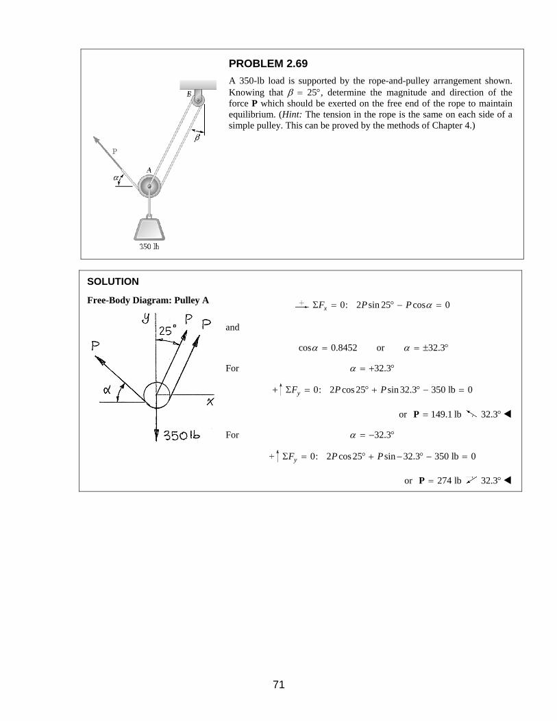
PROBLEM 2.69
A 350-lb load is supported by the rope-and-pulley arrangement shown. Knowing that β = 25°, determine the magnitude and direction of the force P which should be exerted on the free end of the rope to maintain equilibrium. (Hint: The tension in the rope is the same on each side of a simple pulley. This can be proved by the methods of Chapter 4.)
SOLUTION
Free-Body Diagram: Pulley A
0: 2 sin 25 cos 0xF P P αΣ = ° − =
and
cos 0.8452 or 32.3α α= = ± °
For 32.3α = + °
0: 2 cos 25 sin 32.3 350 lb 0yF P PΣ = ° + ° − =
or 149.1 lb=P 32.3°
For 32.3α = − °
0: 2 cos 25 sin 32.3 350 lb 0yF P PΣ = ° + − ° − =
or 274 lb=P 32.3°
71

PROBLEM 2.70
A 350-lb load is supported by the rope-and-pulley arrangement shown. Knowing that 35 ,α = ° determine (a) the angle β, (b) the magnitude of the force P which should be exerted on the free end of the rope to maintain equilibrium. (Hint: The tension in the rope is the same on each side of a simple pulley. This can be proved by the methods of Chapter 4.)
SOLUTION
Free-Body Diagram: Pulley A
0: 2 sin cos 25 0xF P PβΣ = − ° =
Hence:
(a) 1
sin cos 252
β = ° or 24.2β = °
(b) 0: 2 cos sin 35 350 lb 0yF P PβΣ = + ° − =
Hence:
2 cos 24.2 sin 35 350 lb 0P P° + ° − =
or 145.97 lbP = 146.0 lbP =
72
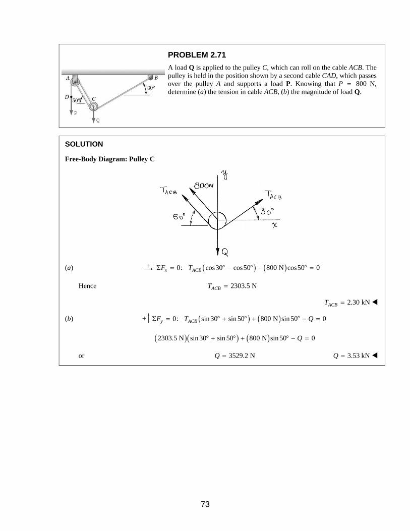
PROBLEM 2.71
A load Q is applied to the pulley C, which can roll on the cable ACB. The pulley is held in the position shown by a second cable CAD, which passes over the pulley A and supports a load P. Knowing that P = 800 N, determine (a) the tension in cable ACB, (b) the magnitude of load Q.
SOLUTION
Free-Body Diagram: Pulley C
(a) ( ) ( )0: cos30 cos50 800 N cos50 0x ACBF TΣ = ° − ° − ° =
Hence 2303.5 NACBT =
2.30 kN=ACBT
(b) ( ) ( )0: sin 30 sin 50 800 N sin 50 0y ACBF T QΣ = ° + ° + ° − =
( )( ) ( )2303.5 N sin 30 sin 50 800 N sin 50 0Q° + ° + ° − =
or 3529.2 NQ = 3.53 kN=Q
73

PROBLEM 2.72
A 2000-N load Q is applied to the pulley C, which can roll on the cable ACB. The pulley is held in the position shown by a second cable CAD, which passes over the pulley A and supports a load P. Determine (a) the tension in the cable ACB, (b) the magnitude of load P.
SOLUTION
Free-Body Diagram: Pulley C
( )0: cos30 cos50 cos50 0x ACBF T PΣ = ° − ° − ° =
or 0.3473 ACBP T= (1)
( )0: sin 30 sin 50 sin 50 2000 N 0y ACBF T PΣ = ° + ° + ° − =
or 1.266 0.766 2000 NACBT P+ = (2)
(a) Substitute Equation (1) into Equation (2):
( )1.266 0.766 0.3473 2000 NACB ACBT T+ =
Hence: 1305.5 NACBT =
1306 NACBT =
(b) Using (1)
( )0.3473 1306 N 453.57 NP = =
454 NP =
74

PROBLEM 2.73
Determine (a) the x, y, and z components of the 200-lb force, (b) the angles θx, θy, and θz that the force forms with the coordinate axes.
SOLUTION
(a) ( )200 lb cos30 cos 25 156.98 lbxF = ° ° =
157.0 lbxF = +
( )200 lb sin 30 100.0 lbyF = ° =
100.0 lbyF = +
( )200 lb cos30 sin 25 73.1996 lbzF = − ° ° = −
73.2 lbzF = −
(b) 156.98
cos200xθ = or 38.3xθ = °
100.0
cos200yθ = or 60.0yθ = °
73.1996
cos200zθ
−= or 111.5zθ = °
75
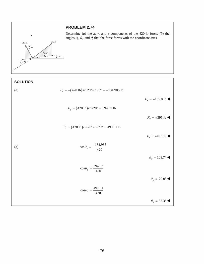
PROBLEM 2.74
Determine (a) the x, y, and z components of the 420-lb force, (b) the angles θx, θy, and θz that the force forms with the coordinate axes.
SOLUTION
(a) ( )420 lb sin 20 sin 70 134.985 lbxF = − ° ° = −
135.0 lbxF = −
( )420 lb cos 20 394.67 lbyF = ° =
395 lbyF = +
( )420 lb sin 20 cos70 49.131 lbzF = ° ° =
49.1 lbzF = +
(b) 134.985
cos420xθ
−=
108.7xθ = °
394.67cos
420yθ =
20.0yθ = °
49.131cos
420zθ =
83.3zθ = °
76
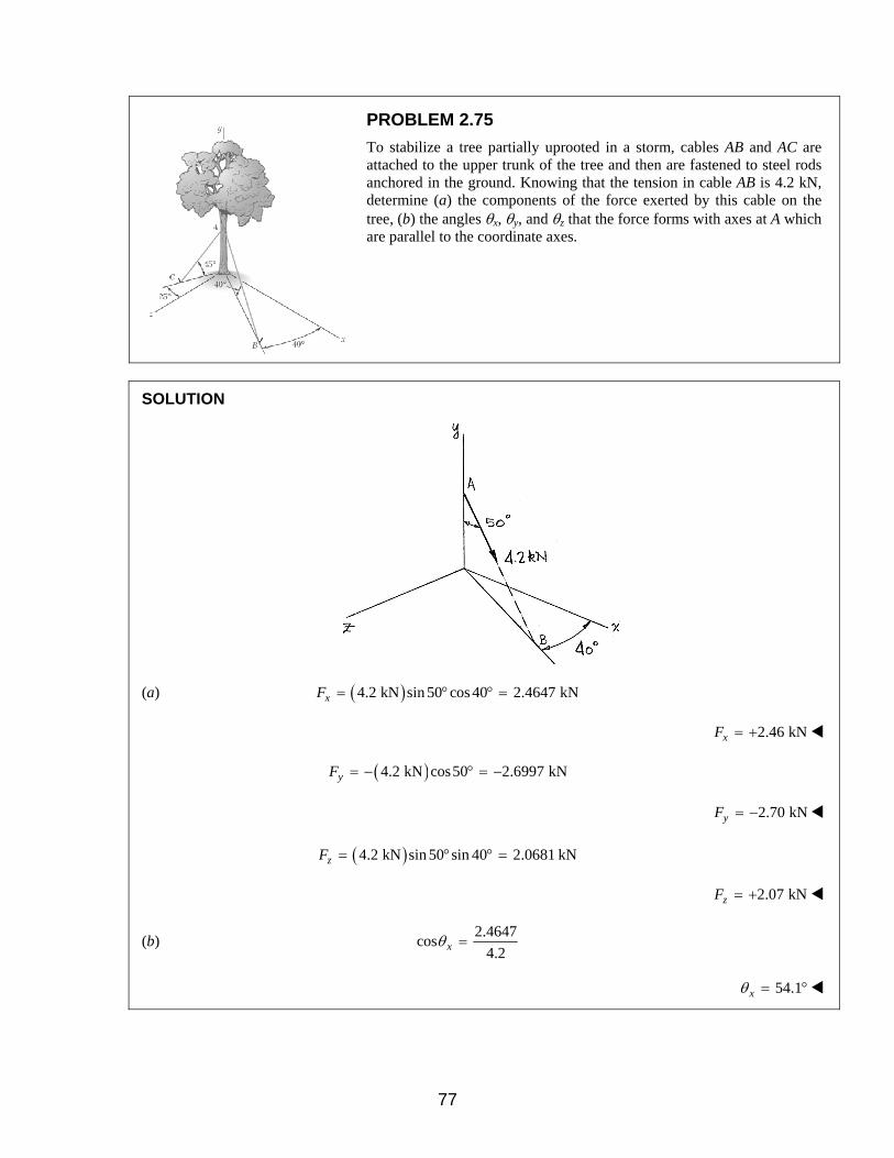
PROBLEM 2.75
To stabilize a tree partially uprooted in a storm, cables AB and AC are attached to the upper trunk of the tree and then are fastened to steel rods anchored in the ground. Knowing that the tension in cable AB is 4.2 kN, determine (a) the components of the force exerted by this cable on the tree, (b) the angles θx, θy, and θz that the force forms with axes at A which are parallel to the coordinate axes.
SOLUTION
(a) ( )4.2 kN sin 50 cos 40 2.4647 kNxF = ° ° =
2.46 kNxF = +
( )4.2 kN cos50 2.6997 kNyF = − ° = −
2.70 kNyF = −
( )4.2 kN sin 50 sin 40 2.0681 kNzF = ° ° =
2.07 kNzF = +
(b) 2.4647
cos4.2xθ =
54.1xθ = °
77

PROBLEM 2.75 CONTINUED
2.7
cos4.2yθ−
=
130.0yθ = °
2.0681
cos4.0zθ =
60.5zθ = °
78

PROBLEM 2.76
To stabilize a tree partially uprooted in a storm, cables AB and AC are attached to the upper trunk of the tree and then are fastened to steel rods anchored in the ground. Knowing that the tension in cable AC is 3.6 kN, determine (a) the components of the force exerted by this cable on the tree, (b) the angles θx, θy, and θz that the force forms with axes at A which are parallel to the coordinate axes.
SOLUTION
(a) ( )3.6 kN cos 45 sin 25 1.0758 kNxF = − ° ° = −
1.076 kNxF = −
( )3.6 kN sin 45 2.546 kNyF = − ° = −
2.55 kNyF = −
( )3.6 kN cos 45 cos 25 2.3071 kNzF = ° ° =
2.31 kNzF = +
(b) 1.0758
cos3.6xθ
−=
107.4xθ = °
79

PROBLEM 2.76 CONTINUED
2.546cos
3.6yθ−
=
135.0yθ = °
2.3071cos
3.6zθ =
50.1zθ = °
80

PROBLEM 2.77
A horizontal circular plate is suspended as shown from three wires which are attached to a support at D and form 30° angles with the vertical. Knowing that the x component of the force exerted by wire AD on the plate is 220.6 N, determine (a) the tension in wire AD, (b) the angles θx, θy, and θz that the force exerted at A forms with the coordinate axes.
SOLUTION
(a) sin 30 sin 50 220.6 NxF F= ° ° = (Given)
220.6 N575.95 N
sin30 sin50= =
° °F
576 N=F
(b) 220.6
cos 0.3830575.95
θ = = =xx
F
F
67.5xθ = °
cos30 498.79 NyF F= ° =
498.79cos 0.86605
575.95y
y
F
Fθ = = =
30.0yθ = °
sin 30 cos50zF F= − ° °
( )575.95 N sin 30 cos50= − ° °
185.107 N= −
185.107cos 0.32139
575.95z
zF
Fθ −
= = = −
108.7zθ = °
81

PROBLEM 2.78
A horizontal circular plate is suspended as shown from three wires which are attached to a support at D and form 30° angles with the vertical. Knowing that the z component of the force exerted by wire BD on the plate is –64.28 N, determine (a) the tension in wire BD, (b) the angles θx, θy, and θz that the force exerted at B forms with the coordinate axes.
SOLUTION
(a) sin 30 sin 40 64.28 NzF F= − ° ° = − (Given)
64.28 N
200.0 Nsin30 sin40
= =° °
F 200 NF =
(b) sin 30 cos 40xF F= − ° °
( )200.0 N sin 30 cos 40= − ° °
76.604 N= −
76.604
cos 0.38302200.0
xx
F
Fθ −
= = = − 112.5xθ = °
cos30 173.2 NyF F= ° =
173.2
cos 0.866200
yy
F
Fθ = = = 30.0yθ = °
64.28 NzF = −
64.28
cos 0.3214200
zz
F
Fθ −
= = = − 108.7zθ = °
82

PROBLEM 2.79
A horizontal circular plate is suspended as shown from three wires which are attached to a support at D and form 30° angles with the vertical. Knowing that the tension in wire CD is 120 lb, determine (a) the components of the force exerted by this wire on the plate, (b) the angles θx, θy, and θz that the force forms with the coordinate axes.
SOLUTION
(a) ( )120 lb sin 30 cos60 30 lbxF = − ° ° = −
30.0 lbxF = −
( )120 lb cos30 103.92 lbyF = ° =
103.9 lb= +yF
( )120 lb sin 30 sin 60 51.96 lbzF = ° ° =
52.0 lbzF = +
(b) 30.0
cos 0.25120
xx
F
Fθ −
= = = −
104.5xθ = °
103.92cos 0.866
120y
y
F
Fθ = = =
30.0yθ = °
51.96cos 0.433
120z
zF
Fθ = = =
64.3zθ = °
83

PROBLEM 2.80
A horizontal circular plate is suspended as shown from three wires which are attached to a support at D and form 30° angles with the vertical. Knowing that the x component of the forces exerted by wire CD on the plate is –40 lb, determine (a) the tension in wire CD, (b) the angles θx, θy, and θz that the force exerted at C forms with the coordinate axes.
SOLUTION
(a) sin 30 cos60 40 lbxF F= − ° ° = − (Given)
40 lb160 lb
sin30 cos60= =
° °F
160.0 lbF =
(b) 40
cos 0.25160
xx
F
Fθ −
= = = −
104.5xθ = °
( )160 lb cos30 103.92 lbyF = ° =
103.92
cos 0.866160
yy
F
Fθ = = =
30.0yθ = °
( )160 lb sin 30 sin 60 69.282 lbzF = ° ° =
69.282cos 0.433
160z
zF
Fθ = = =
64.3zθ = °
84

PROBLEM 2.81
Determine the magnitude and direction of the force
( ) ( ) ( )800 lb 260 lb 320 lb .= + −F i j k
SOLUTION
( ) ( ) ( )2 2 22 2 2 800 lb 260 lb 320 lbx y zF F F F= + + = + + − 900 lbF =
800
cos 0.8889900
xx
F
Fθ = = = 27.3xθ = °
260
cos 0.2889900
yy
F
Fθ = = = 73.2yθ = °
320
cos 0.3555900
zz
F
Fθ −
= = = − 110.8zθ = °
85

PROBLEM 2.82
Determine the magnitude and direction of the force
( ) ( ) ( )400 N 1200 N 300 N .= − +F i j k
SOLUTION
( ) ( ) ( )2 2 22 2 2 400 N 1200 N 300 Nx y zF F F F= + + = + − + 1300 NF =
400
cos 0.307691300
xx
F
Fθ = = = 72.1xθ = °
1200
cos 0.923071300
yy
F
Fθ −
= = = − 157.4yθ = °
300
cos 0.230761300
zz
F
Fθ = = = 76.7zθ = °
86

PROBLEM 2.83
A force acts at the origin of a coordinate system in a direction defined by the angles θx = 64.5° and θz = 55.9°. Knowing that the y component of the force is –200 N, determine (a) the angle θy, (b) the other components and the magnitude of the force.
SOLUTION
(a) We have
( ) ( ) ( ) ( ) ( ) ( )2 2 22 2 2cos cos cos 1 cos 1 cos cosx y z y y zθ θ θ θ θ θ+ + = ⇒ = − −
Since 0yF < we must have cos 0yθ <
Thus, taking the negative square root, from above, we have:
( ) ( )2 2cos 1 cos64.5 cos55.9 0.70735yθ = − − ° − ° = − 135.0yθ = °
(b) Then:
200 N
282.73 Ncos 0.70735
y
y
FF
θ−
= = =−
and ( )cos 282.73 N cos64.5x xF F θ= = ° 121.7 NxF =
( )cos 282.73 N cos55.9z zF F θ= = ° 158.5 NyF =
283 NF =
87

PROBLEM 2.84
A force acts at the origin of a coordinate system in a direction defined by the angles θx = 75.4° and θy = 132.6°. Knowing that the z component of the force is –60 N, determine (a) the angle θz, (b) the other components and the magnitude of the force.
SOLUTION
(a) We have
( ) ( ) ( ) ( ) ( ) ( )2 2 22 2 2cos cos cos 1 cos 1 cos cosx y z y y zθ θ θ θ θ θ+ + = ⇒ = − −
Since 0zF < we must have cos 0zθ <
Thus, taking the negative square root, from above, we have:
( ) ( )2 2cos 1 cos75.4 cos132.6 0.69159zθ = − − ° − ° = − 133.8zθ = °
(b) Then:
60 N
86.757 Ncos 0.69159
z
z
FF
θ−
= = =−
86.8 NF =
and ( )cos 86.8 N cos75.4x xF F θ= = ° 21.9 NxF =
( )cos 86.8 N cos132.6y yF F θ= = ° 58.8 NyF = −
88
PROBLEM 2.85
A force F of magnitude 400 N acts at the origin of a coordinate system. Knowing that θx = 28.5°, Fy = –80 N, and Fz > 0, determine (a) the components Fx and Fz, (b) the angles θy and θz.
SOLUTION
(a) Have
( )cos 400 N cos 28.5x xF F θ= = ° 351.5 NxF =
Then:
2 2 2 2x y zF F F F= + +
So: ( ) ( ) ( )2 2 2 2400 N 352.5 N 80 N zF= + − +
Hence:
( ) ( ) ( )2 2 2400 N 351.5 N 80 NzF = + − − − 173.3 NzF =
(b)
80
cos 0.20400
yy
F
Fθ −
= = = − 101.5yθ = °
173.3
cos 0.43325400
zz
F
Fθ = = = 64.3zθ = °
89

PROBLEM 2.86
A force F of magnitude 600 lb acts at the origin of a coordinate system. Knowing that Fx = 200 lb, θz = 136.8°, Fy < 0, determine (a) the components Fy and Fz, (b) the angles θx and θy.
SOLUTION
(a) ( )cos 600 lb cos136.8z zF F θ= = °
437.4 lb= − 437 lbzF = −
Then:
2 2 2 2x y zF F F F= + +
So: ( ) ( ) ( ) ( )22 2 2600 lb 200 lb 437.4 lbyF= + + −
Hence: ( ) ( ) ( )2 2 2600 lb 200 lb 437.4 lbyF = − − − −
358.7 lb= − 359 lbyF = −
(b)
200
cos 0.333600
xx
F
Fθ = = = 70.5xθ = °
358.7
cos 0.59783600
yy
F
Fθ −
= = = − 126.7yθ = °
90

PROBLEM 2.87
A transmission tower is held by three guy wires anchored by bolts at B, C, and D. If the tension in wire AB is 2100 N, determine the components of the force exerted by the wire on the bolt at B.
SOLUTION
( ) ( ) ( )4 m 20 m 5 mBA = + −i j k
( ) ( ) ( )2 2 24 m 20 m 5 m 21 mBA = + + − =
( ) ( ) ( )2100 N4 m 20 m 5 m
21 mBABA
F FBA
= = = + − F i j kλ
( ) ( ) ( )400 N 2000 N 500 N= + −F i j k
400 N, 2000 N, 500 Nx y zF F F= + = + = −
91

PROBLEM 2.88
A transmission tower is held by three guy wires anchored by bolts at B, C, and D. If the tension in wire AD is 1260 N, determine the components of the force exerted by the wire on the bolt at D.
SOLUTION
( ) ( ) ( )4 m 20 m 14.8 mDA = + +i j k
( ) ( ) ( )2 2 24 m 20 m 14.8 m 25.2 mDA = + + =
( ) ( ) ( )1260 N4 m 20 m 14.8 m
25.2 mDADA
F FDA
= = = + + F i j kλ
( ) ( ) ( )200 N 1000 N 740 N= + +F i j k
200 N, 1000 N, 740 Nx y zF F F= + = + = +
92

PROBLEM 2.89
A rectangular plate is supported by three cables as shown. Knowing that the tension in cable AB is 204 lb, determine the components of the force exerted on the plate at B.
SOLUTION
( ) ( ) ( )32 in. 48 in. 36 in.BA = + −i j k
( ) ( ) ( )2 2 232 in. 48 in. 36 in. 68 in.BA = + + − =
( ) ( ) ( )204 lb32 in. 48 in. 36 in.
68 in.BABA
F FBA
= = = + − F i j kλ
( ) ( ) ( )96 lb 144 lb 108 lb= + −F i j k
96.0 lb, 144.0 lb, 108.0 lbx y zF F F= + = + = −
93

PROBLEM 2.90
A rectangular plate is supported by three cables as shown. Knowing that the tension in cable AD is 195 lb, determine the components of the force exerted on the plate at D.
SOLUTION
( ) ( ) ( )25 in. 48 in. 36 in.DA = − + +i j k
( ) ( ) ( )2 2 225 in. 48 in. 36 in. 65 in.DA = − + + =
( ) ( ) ( )195 lb25 in. 48 in. 36 in.
65 in.DADA
F FDA
= = = − + + F i j kλ
( ) ( ) ( )75 lb 144 lb 108 lb= − + +F i j k
75.0 lb, 144.0 lb, 108.0 lbx y zF F F= − = + = +
94
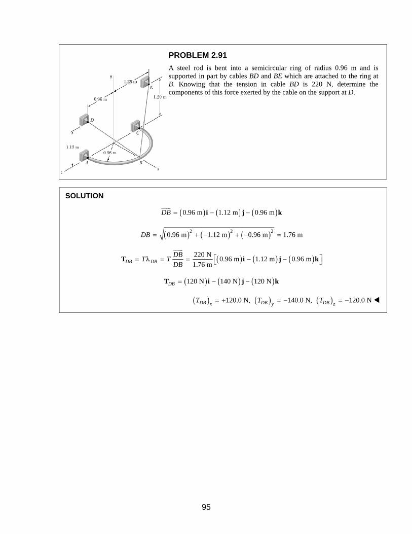
PROBLEM 2.91
A steel rod is bent into a semicircular ring of radius 0.96 m and is supported in part by cables BD and BE which are attached to the ring at B. Knowing that the tension in cable BD is 220 N, determine the components of this force exerted by the cable on the support at D.
SOLUTION
( ) ( ) ( )0.96 m 1.12 m 0.96 mDB = − −i j k
( ) ( ) ( )2 2 20.96 m 1.12 m 0.96 m 1.76 mDB = + − + − =
( ) ( ) ( )220 N0.96 m 1.12 m 0.96 m
1.76 mDB DBDB
T TDB
= = = − − T i j kλ
( ) ( ) ( )120 N 140 N 120 NDB = − −T i j k
( ) ( ) ( )120.0 N, 140.0 N, 120.0 NDB DB DBx y zT T T= + = − = −
95

PROBLEM 2.92
A steel rod is bent into a semicircular ring of radius 0.96 m and is supported in part by cables BD and BE which are attached to the ring at B. Knowing that the tension in cable BE is 250 N, determine the components of this force exerted by the cable on the support at E.
SOLUTION
( ) ( ) ( )0.96 m 1.20 m 1.28 mEB = − +i j k
( ) ( ) ( )2 2 20.96 m 1.20 m 1.28 m 2.00 mEB = + − + =
( ) ( ) ( )250 N0.96 m 1.20 m 1.28 m
2.00 mEB EBEB
T TEB
= = = − + T i j kλ
( ) ( ) ( )120 N 150 N 160 NEB = − +T i j k
( ) ( ) ( )120.0 N, 150.0 N, 160.0 NEB EB EBx y zT T T= + = − = +
96

PROBLEM 2.93
Find the magnitude and direction of the resultant of the two forces shown knowing that 500 NP = and 600 N.Q =
SOLUTION
( )[ ]500 lb cos30 sin15 sin 30 cos30 cos15= − ° ° + ° + ° °P i j k
( )[ ]500 lb 0.2241 0.50 0.8365= − + +i j k
( ) ( ) ( )112.05 lb 250 lb 418.25 lb= − + +i j k
( )[ ]600 lb cos 40 cos 20 sin 40 cos 40 sin 20= ° ° + ° − ° °Q i j k
( )[ ]600 lb 0.71985 0.64278 0.26201= + −i j k
( ) ( ) ( )431.91 lb 385.67 lb 157.206 lb= + −i j k
( ) ( ) ( )319.86 lb 635.67 lb 261.04 lb= + = + +R P Q i j k
( ) ( ) ( )2 2 2319.86 lb 635.67 lb 261.04 lb 757.98 lbR = + + =
758 lbR =
319.86 lbcos 0.42199
757.98 lbx
xR
Rθ = = =
65.0xθ = °
635.67 lbcos 0.83864
757.98 lby
y
R
Rθ = = =
33.0yθ = °
261.04 lbcos 0.34439
757.98 lbz
zR
Rθ = = =
69.9zθ = °
97

PROBLEM 2.94
Find the magnitude and direction of the resultant of the two forces shown knowing that P = 600 N and Q = 400 N.
SOLUTION
Using the results from 2.93:
( )[ ]600 lb 0.2241 0.50 0.8365= − + +P i j k
( ) ( ) ( )134.46 lb 300 lb 501.9 lb= − + +i j k
( )[ ]400 lb 0.71985 0.64278 0.26201= + −Q i j k
( ) ( ) ( )287.94 lb 257.11 lb 104.804 lb= + −i j k
( ) ( ) ( )153.48 lb 557.11 lb 397.10 lb= + = + +R P Q i j k
( ) ( ) ( )2 2 2153.48 lb 557.11 lb 397.10 lb 701.15 lbR = + + =
701 lbR =
153.48 lbcos 0.21890
701.15 lbx
xR
Rθ = = =
77.4xθ = °
557.11 lbcos 0.79457
701.15 lby
y
R
Rθ = = =
37.4yθ = °
397.10 lbcos 0.56637
701.15 lbz
zR
Rθ = = =
55.5zθ = °
98

PROBLEM 2.95
Knowing that the tension is 850 N in cable AB and 1020 N in cable AC, determine the magnitude and direction of the resultant of the forces exerted at A by the two cables.
SOLUTION
( ) ( ) ( )400 mm 450 mm 600 mmAB = − +i j k
( ) ( ) ( )2 2 2400 mm 450 mm 600 mm 850 mmAB = + − + =
( ) ( ) ( )1000 mm 450 mm 600 mmAC = − +i j k
( ) ( ) ( )2 2 21000 mm 450 mm 600 mm 1250 mmAC = + − + =
( ) ( ) ( ) ( )400 mm 450 mm 600 mm850 N
850 mmAB AB ABAB
ABT T
AB
− += = =
i j kT λ
( ) ( ) ( )400 N 450 N 600 NAB
= − +T i j k
( ) ( ) ( ) ( )1000 mm 450 mm 600 mm1020 N
1250 mmAC AC ACAC
ACT T
AC
− += = =
i j kT λ
( ) ( ) ( )816 N 367.2 N 489.6 NAC
= − +T i j k
( ) ( ) ( )1216 N 817.2 N 1089.6 NAB AC= + = − +R T T i j k
Then: 1825.8 NR = 1826 NR =
and 1216
cos 0.666011825.8xθ = = 48.2xθ = °
817.2
cos 0.447581825.8yθ−
= = − 116.6yθ = °
1089.6
cos 0.596781825.8zθ = = 53.4zθ = °
99

PROBLEM 2.96
Assuming that in Problem 2.95 the tension is 1020 N in cable AB and 850 N in cable AC, determine the magnitude and direction of the resultant of the forces exerted at A by the two cables.
SOLUTION
( ) ( ) ( )400 mm 450 mm 600 mmAB = − +i j k
( ) ( ) ( )2 2 2400 mm 450 mm 600 mm 850 mmAB = + − + =
( ) ( ) ( )1000 mm 450 mm 600 mmAC = − +i j k
( ) ( ) ( )2 2 21000 mm 450 mm 600 mm 1250 mmAC = + − + =
( ) ( ) ( ) ( )400 mm 450 mm 600 mm1020 N
850 mmAB AB AB ABAB
T TAB
− += = =
i j kT λ
( ) ( ) ( )480 N 540 N 720 NAB = − +T i j k
( ) ( ) ( ) ( )1000 mm 450 mm 600 mm850 N
1250 mmAC AC AC ACAC
T TAC
− += = =
i j kT λ
( ) ( ) ( )680 N 306 N 408 NAC = − +T i j k
( ) ( ) ( )1160 N 846 N 1128 NAB AC= + = − +R T T i j k
Then: 1825.8 NR = 1826 NR =
and 1160
cos 0.63531825.8xθ = = 50.6xθ = °
846
cos 0.46341825.8yθ−
= = − 117.6yθ = °
1128
cos 0.61781825.8zθ = = 51.8zθ = °
100

PROBLEM 2.97
For the semicircular ring of Problem 2.91, determine the magnitude and direction of the resultant of the forces exerted by the cables at B knowing that the tensions in cables BD and BE are 220 N and 250 N, respectively.
SOLUTION
For the solutions to Problems 2.91 and 2.92, we have
( ) ( ) ( )120 N 140 N 120 NBD = − + +T i j k
( ) ( ) ( )120 N 150 N 160 NBE = − + −T i j k
Then:
B BD BE= +R T T
( ) ( ) ( )240 N 290 N 40 N= − + −i j k
and 378.55 NR = 379 NBR =
240cos 0.6340
378.55xθ = − = −
129.3xθ = °
290cos 0.7661
378.55yθ = = −
40.0yθ = °
40cos 0.1057
378.55zθ = − = −
96.1zθ = °
101
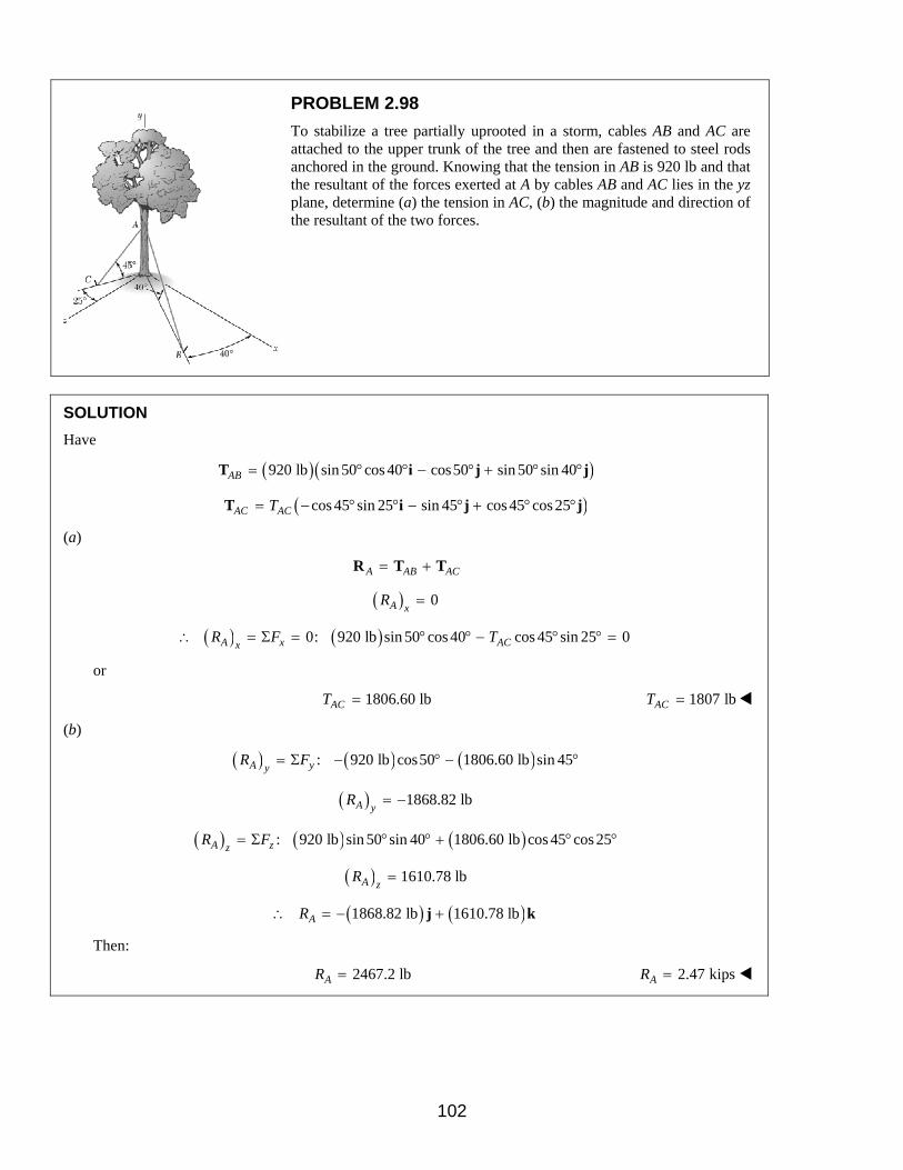
PROBLEM 2.98
To stabilize a tree partially uprooted in a storm, cables AB and AC are attached to the upper trunk of the tree and then are fastened to steel rods anchored in the ground. Knowing that the tension in AB is 920 lb and that the resultant of the forces exerted at A by cables AB and AC lies in the yz plane, determine (a) the tension in AC, (b) the magnitude and direction of the resultant of the two forces.
SOLUTION
Have
( )( )920 lb sin 50 cos 40 cos50 sin 50 sin 40AB = ° ° − ° + ° °T i j j
( )cos 45 sin 25 sin 45 cos 45 cos 25AC ACT= − ° ° − ° + ° °T i j j
(a)
A AB AC= +R T T
( ) 0A xR =
∴ ( ) ( )0: 920 lb sin 50 cos 40 cos 45 sin 25 0A x ACxR F T= Σ = ° ° − ° ° =
or
1806.60 lbACT = 1807 lbACT =
(b)
( ) ( ) ( ): 920 lb cos50 1806.60 lb sin 45A yyR F= Σ − ° − °
( ) 1868.82 lbA yR = −
( ) ( ) ( ): 920 lb sin 50 sin 40 1806.60 lb cos 45 cos 25A zzR F= Σ ° ° + ° °
( ) 1610.78 lbA zR =
∴ ( ) ( )1868.82 lb 1610.78 lbAR = − +j k
Then:
2467.2 lbAR = 2.47 kipsAR =
102

PROBLEM 2.98 CONTINUED
and
0
cos 02467.2xθ = = 90.0xθ = °
1868.82
cos 0.75602467.2yθ−
= = − 139.2yθ = °
1610.78
cos 0.652882467.2zθ = = 49.2zθ = °
103

PROBLEM 2.99
To stabilize a tree partially uprooted in a storm, cables AB and AC are attached to the upper trunk of the tree and then are fastened to steel rods anchored in the ground. Knowing that the tension in AC is 850 lb and that the resultant of the forces exerted at A by cables AB and AC lies in the yz plane, determine (a) the tension in AB, (b) the magnitude and direction of the resultant of the two forces.
SOLUTION
Have
( )sin 50 cos 40 cos50 sin 50 sin 40AB ABT= ° ° − ° + ° °T i j j
( )( )850 lb cos 45 sin 25 sin 45 cos 45 cos 25AC = − ° ° − ° + ° °T i j j
(a)
( ) 0A xR =
∴ ( ) ( )0: sin 50 cos 40 850 lb cos 45 sin 25 0A x ABxR F T= Σ = ° ° − ° ° =
432.86 lbABT = 433 lbABT =
(b)
( ) ( ) ( ): 432.86 lb cos50 850 lb sin 45A yyR F= Σ − ° − °
( ) 879.28 lbA yR = −
( ) ( ) ( ): 432.86 lb sin 50 sin 40 850 lb cos 45 cos 25A zzR F= Σ ° ° + ° °
( ) 757.87 lbA zR =
∴ ( ) ( )879.28 lb 757.87 lbA = − +R j k
1160.82 lbAR = 1.161 kipsAR =
0
cos 01160.82xθ = = 90.0xθ = °
879.28
cos 0.757461160.82yθ−
= = − 139.2yθ = °
757.87
cos 0.652871160.82zθ = = 49.2zθ = °
104

PROBLEM 2.100
For the plate of Problem 2.89, determine the tension in cables AB and AD knowing that the tension if cable AC is 27 lb and that the resultant of the forces exerted by the three cables at A must be vertical.
SOLUTION
With:
( ) ( ) ( )45 in. 48 in. 36 in.AC = − +i j k
( ) ( ) ( )2 2 245 in. 48 in. 36 in. 75 in.AC = + − + =
( ) ( ) ( )27 lb45 in. 48 in. 36 in.
75 in.AC AC AC ACAC
T TAC
= = = − + T i j kλ
( ) ( ) ( )16.2 lb 17.28 lb 12.96AC = − +T i j k
and
( ) ( ) ( )32 in. 48 in. 36 in.AB = − − +i j k
( ) ( ) ( )2 2 232 in. 48 in. 36 in. 68 in.AB = − + − + =
( ) ( ) ( )32 in. 48 in. 36 in.68 in.
ABAB AB AB AB
AB TT T
AB = = = − − + T i j kλ
( )0.4706 0.7059 0.5294AB ABT= − − +T i j k
and
( ) ( ) ( )25 in. 48 in. 36 in.AD = − −i j k
( ) ( ) ( )2 2 225 in. 48 in. 36 in. 65 in.AD = + − + =
( ) ( ) ( )25 in. 48 in. 36 in.65 in.
ADAD AD AD AD
AD TT T
AD = = = − − T i j kλ
( )0.3846 0.7385 0.5538AD ADT= − −T i j k
105
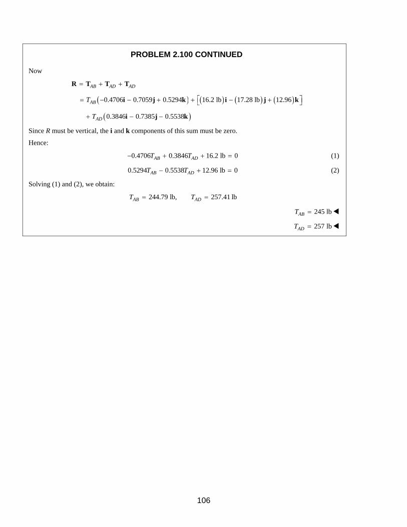
PROBLEM 2.100 CONTINUED
Now
AB AD AD= + +R T T T
( ) ( ) ( ) ( )0.4706 0.7059 0.5294 16.2 lb 17.28 lb 12.96ABT = − − + + − + i j k i j k
( )0.3846 0.7385 0.5538ADT+ − −i j k
Since R must be vertical, the i and k components of this sum must be zero.
Hence:
0.4706 0.3846 16.2 lb 0AB ADT T− + + = (1)
0.5294 0.5538 12.96 lb 0AB ADT T− + = (2)
Solving (1) and (2), we obtain:
244.79 lb, 257.41 lbAB ADT T= =
245 lbABT =
257 lbADT =
106

PROBLEM 2.101
The support assembly shown is bolted in place at B, C, and D and supports a downward force P at A. Knowing that the forces in members AB, AC, and AD are directed along the respective members and that the force in member AB is 146 N, determine the magnitude of P.
SOLUTION
Note that AB, AC, and AD are in compression.
Have
( ) ( ) ( )2 2 2220 mm 192 mm 0 292 mmBAd = − + + =
( ) ( ) ( )2 2 2192 mm 192 mm 96 mm 288 mmDAd = + + =
( ) ( ) ( )2 2 20 192 mm 144 mm 240 mmCAd = + + − =
and ( ) ( )146 N220 mm 192 mm
292 mmBA BA BAF = = − + F i jλ
( ) ( )110 N 96 N= − +i j
( ) ( )192 mm 144 mm240 mm
CACA CA CA
FF = = − F j kλ
( )0.80 0.60CAF= −j k
( ) ( ) ( )192 mm 192 mm 96 mm288 mm
DADA DA DA
FF = = + + F i j kλ
[ ]0.66667 0.66667 0.33333DAF= + +i j k
With P= −P j
At A: 0: 0BA CA DAΣ = + + + =F F F F P
i-component: ( )110 N 0.66667 0DAF− + = or 165 NDAF =
j-component: ( )96 N 0.80 0.66667 165 N 0CAF P+ + − = (1)
k-component: ( )0.60 0.33333 165 N 0CAF− + = (2)
Solving (2) for CAF and then using that result in (1), gives 279 NP =
107

PROBLEM 2.102
The support assembly shown is bolted in place at B, C, and D and supports a downward force P at A. Knowing that the forces in members AB, AC, and AD are directed along the respective members and that P = 200 N, determine the forces in the members.
SOLUTION
With the results of 2.101:
( ) ( )220 mm 192 mm292 mm
BABA BA BA
FF = = − + F i jλ
[ ]0.75342 0.65753 NBAF= − +i j
( ) ( )192 mm 144 mm240 mm
CACA CA CA
FF = = − F j kλ
( )0.80 0.60CAF= −j k
( ) ( ) ( )192 mm 192 mm 96 mm288 mm
DADA DA DA
FF = = + + F i j kλ
[ ]0.66667 0.66667 0.33333DAF= + +i j k
With: ( )200 N= −P j
At A: 0: 0BA CA DAΣ = + + + =F F F F P
Hence, equating the three (i, j, k) components to 0 gives three equations
i-component: 0.75342 0.66667 0BA DAF F− + = (1)
j-component: 0.65735 0.80 0.66667 200 N 0BA CA DAF F F+ + − = (2)
k-component: 0.60 0.33333 0CA DAF F− + = (3)
Solving (1), (2), and (3), gives
DA104.5 N, 65.6 N, 118.1 NBA CAF F F= = =
104.5 NBAF =
65.6 NCAF =
118.1 NDAF =
108
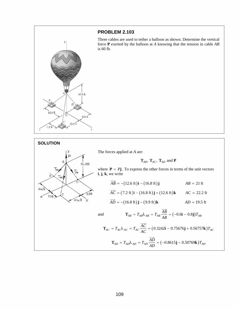
PROBLEM 2.103
Three cables are used to tether a balloon as shown. Determine the vertical force P exerted by the balloon at A knowing that the tension in cable AB is 60 lb.
SOLUTION
The forces applied at A are:
, , and AB AC ADT T T P
where P=P j . To express the other forces in terms of the unit vectors i, j, k, we write
( ) ( )12.6 ft 16.8 ftAB = − −i j 21 ftAB =
( ) ( ) ( )7.2 ft 16.8 ft 12.6 ft 22.2 ftAC AC= − + =i j k
( ) ( )16.8 ft 9.9 ftAD = − −j k 19.5 ftAD =
and ( )0.6 0.8AB AB AB AB ABAB
T T TAB
= = = − −T i jλ
( )0.3242 0.75676 0.56757AC AC AC AC ACAC
T T TAC
= = = − +T i j kλ
( )0.8615 0.50769AD AD AD AD ADAD
T T TAD
= = = − −T j kλ
109
PROBLEM 2.103 CONTINUED
Equilibrium Condition
0: 0AB AC ADF PΣ = + + + =T T T j
Substituting the expressions obtained for , , and AB AC ADT T T and factoring i, j, and k:
( ) ( )0.6 0.3242 0.8 0.75676 0.8615AB AC AB AC ADT T T T T P− + + − − − +i j
( )0.56757 0.50769 0AC ADT T+ − =k
Equating to zero the coefficients of i, j, k:
0.6 0.3242 0AB ACT T− + = (1)
0.8 0.75676 0.8615 0AB AC ADT T T P− − − + = (2)
0.56757 0.50769 0AC ADT T− = (3)
Setting 60 lbABT = in (1) and (2), and solving the resulting set of equations gives
111 lbACT =
124.2 lbADT =
239 lb=P
110

PROBLEM 2.104
Three cables are used to tether a balloon as shown. Determine the vertical force P exerted by the balloon at A knowing that the tension in cable AC is 100 lb.
SOLUTION
See Problem 2.103 for the figure and the analysis leading to the linear algebraic Equations (1), (2), and (3) below:
0.6 0.3242 0AB ACT T− + = (1)
0.8 0.75676 0.8615 0AB AC ADT T T P− − − + = (2)
0.56757 0.50769 0AC ADT T− = (3)
Substituting 100 lbACT = in Equations (1), (2), and (3) above, and solving the resulting set of equations using conventional algorithms gives
54 lbABT =
112 lbADT =
215 lb=P
111

PROBLEM 2.105
The crate shown in Figure P2.105 and P2.108 is supported by three cables. Determine the weight of the crate knowing that the tension in cable AB is 3 kN.
SOLUTION
The forces applied at A are:
, , and AB AC ADT T T P
where P=P j . To express the other forces in terms of the unit vectors i, j, k, we write
( ) ( ) ( )0.72 m 1.2 m 0.54 m ,AB = − + −i j k 1.5 mAB =
( ) ( )1.2 m 0.64 m ,AC = +j k 1.36 mAC =
( ) ( ) ( )0.8 m 1.2 m 0.54 m ,AD = + −i j k 1.54 mAD =
and ( )0.48 0.8 0.36AB AB AB AB ABAB
T T TAB
= = = − + −T i j kλ
( )0.88235 0.47059AC AC AC AC ACAC
T T TAC
= = = +T j kλ
( )0.51948 0.77922 0.35065AD AD AD AD ADAD
T T TAD
= = = + −T i j kλ
Equilibrium Condition with W= −W j
0: 0AB AC ADF WΣ = + + − =T T T j
Substituting the expressions obtained for , , and AB AC ADT T T and factoring i, j, and k:
( ) ( )0.48 0.51948 0.8 0.88235 0.77922AB AD AB AC ADT T T T T W− + + + + −i j
( )0.36 0.47059 0.35065 0AB AC ADT T T+ − + − =k
112

PROBLEM 2.105 CONTINUED
Equating to zero the coefficients of i, j, k:
0.48 0.51948 0AB ADT T− + =
0.8 0.88235 0.77922 0AB AC ADT T T W+ + − =
0.36 0.47059 0.35065 0AB AC ADT T T− + − =
Substituting 3 kNABT = in Equations (1), (2) and (3) and solving the resulting set of equations, using conventional algorithms for solving linear algebraic equations, gives
4.3605 kNACT =
2.7720 kNADT =
8.41 kNW =
113
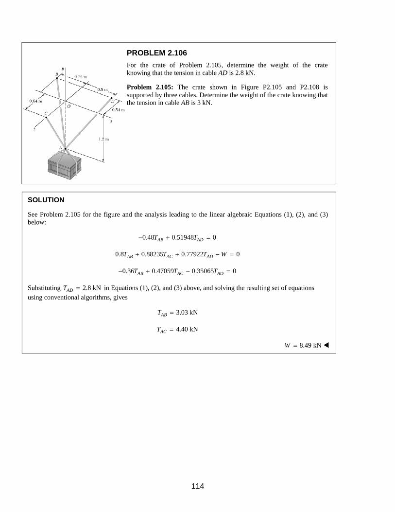
PROBLEM 2.106
For the crate of Problem 2.105, determine the weight of the crate knowing that the tension in cable AD is 2.8 kN.
Problem 2.105: The crate shown in Figure P2.105 and P2.108 is supported by three cables. Determine the weight of the crate knowing that the tension in cable AB is 3 kN.
SOLUTION
See Problem 2.105 for the figure and the analysis leading to the linear algebraic Equations (1), (2), and (3) below:
0.48 0.51948 0AB ADT T− + =
0.8 0.88235 0.77922 0AB AC ADT T T W+ + − =
0.36 0.47059 0.35065 0AB AC ADT T T− + − =
Substituting 2.8 kNADT = in Equations (1), (2), and (3) above, and solving the resulting set of equations using conventional algorithms, gives
3.03 kNABT =
4.40 kNACT =
8.49 kNW =
114

PROBLEM 2.107
For the crate of Problem 2.105, determine the weight of the crate knowing that the tension in cable AC is 2.4 kN.
Problem 2.105: The crate shown in Figure P2.105 and P2.108 is supported by three cables. Determine the weight of the crate knowing that the tension in cable AB is 3 kN.
SOLUTION
See Problem 2.105 for the figure and the analysis leading to the linear algebraic Equations (1), (2), and (3) below:
0.48 0.51948 0AB ADT T− + =
0.8 0.88235 0.77922 0AB AC ADT T T W+ + − =
0.36 0.47059 0.35065 0AB AC ADT T T− + − =
Substituting 2.4 kNACT = in Equations (1), (2), and (3) above, and solving the resulting set of equations using conventional algorithms, gives
1.651 kNABT =
1.526 kNADT =
4.63 kNW =
115

PROBLEM 2.108
A 750-kg crate is supported by three cables as shown. Determine the tension in each cable.
SOLUTION
See Problem 2.105 for the figure and the analysis leading to the linear algebraic Equations (1), (2), and (3) below:
0.48 0.51948 0AB ADT T− + =
0.8 0.88235 0.77922 0AB AC ADT T T W+ + − =
0.36 0.47059 0.35065 0AB AC ADT T T− + − =
Substituting ( )( )2750 kg 9.81 m/s 7.36 kNW = = in Equations (1), (2), and (3) above, and solving the
resulting set of equations using conventional algorithms, gives
2.63 kNABT =
3.82 kNACT =
2.43 kNADT =
116

PROBLEM 2.109
A force P is applied as shown to a uniform cone which is supported by three cords, where the lines of action of the cords pass through the vertex A of the cone. Knowing that P = 0 and that the tension in cord BE is 0.2 lb, determine the weight W of the cone.
SOLUTION
Note that because the line of action of each of the cords passes through the vertex A of the cone, the cords all have the same length, and the unit vectors lying along the cords are parallel to the unit vectors lying along the generators of the cone.
Thus, for example, the unit vector along BE is identical to the unit vector along the generator AB.
Hence: cos 45 8 sin 45
65AB BE
° + − °= =
i j kλ λ
It follows that: cos 45 8 sin 45
65BE BE BE BET T
° + − ° = =
i j kT λ
cos30 8 sin 30
65CF CF CF CFT T
° + + ° = =
i j kT λ
cos15 8 sin15
65DG DG DG DGT T
− ° + − ° = =
i j kT λ
117

PROBLEM 2.109 CONTINUED
At A: 0: 0BE CF DGΣ = + + + + =F T T T W P
Then, isolating the factors of i, j, and k, we obtain three algebraic equations:
: cos 45 cos30 cos15 065 65 65BE CF DGT T T
P° + ° − ° + =i
or cos 45 cos30 cos15 65 0BE CF DGT T T P° + ° − ° + = (1)
8 8 8
: 065 65 65
BE CF DGT T T W+ + − =j
or 65
08BE CF DGT T T W+ + − = (2)
: sin 45 sin 30 sin15 065 65 65BE CF DGT T T
− ° + ° − ° =k
or sin 45 sin 30 sin15 0BE CF DGT T T− ° + ° − ° = (3)
With 0P = and the tension in cord 0.2 lb:BE =
Solving the resulting Equations (1), (2), and (3) using conventional methods in Linear Algebra (elimination, matrix methods or iteration – with MATLAB or Maple, for example), we obtain:
0.669 lbCFT =
0.746 lbDGT =
1.603 lbW =
118

PROBLEM 2.110
A force P is applied as shown to a uniform cone which is supported by three cords, where the lines of action of the cords pass through the vertex A of the cone. Knowing that the cone weighs 1.6 lb, determine the range of values of P for which cord CF is taut.
SOLUTION
See Problem 2.109 for the Figure and the analysis leading to the linear algebraic Equations (1), (2), and (3) below:
: cos 45 cos30 cos15 65 0BE CF DGT T T P° + ° − ° + =i (1)
65
: 08BE CF DGT T T W+ + − =j (2)
: sin 45 sin 30 sin15 0BE CF DGT T T− ° + ° − ° =k (3)
With 1.6 lbW = , the range of values of P for which the cord CF is taut can found by solving Equations (1), (2), and (3) for the tension CFT as a function of P and requiring it to be positive ( 0).>
Solving (1), (2), and (3) with unknown P, using conventional methods in Linear Algebra (elimination, matrix methods or iteration – with MATLAB or Maple, for example), we obtain:
( )1.729 0.668 lbCFT P= − +
Hence, for 0CFT > 1.729 0.668 0P− + >
or 0.386 lbP <
0 0.386 lbP∴ < <
119

PROBLEM 2.111
A transmission tower is held by three guy wires attached to a pin at A and anchored by bolts at B, C, and D. If the tension in wire AB is 3.6 kN, determine the vertical force P exerted by the tower on the pin at A.
SOLUTION
The force in each cable can be written as the product of the magnitude of the force and the unit vector along the cable. That is, with
( ) ( ) ( )18 m 30 m 5.4 mAC = − +i j k
( ) ( ) ( )2 2 218 m 30 m 5.4 m 35.4 mAC = + − + =
( ) ( ) ( )18 m 30 m 5.4 m35.4 m
ACAC AC AC
AC TT T
AC = = = − + T i j kλ
( )0.5085 0.8475 0.1525AC ACT= − +T i j k
and ( ) ( ) ( )6 m 30 m 7.5 mAB = − − +i j k
( ) ( ) ( )2 2 26 m 30 m 7.5 m 31.5 mAB = − + − + =
( ) ( ) ( )6 m 30 m 7.5 m31.5 m
ABAB AB AB
AB TT T
AB = = = − − + T i j kλ
( )0.1905 0.9524 0.2381AB ABT= − − +T i j k
Finally ( ) ( ) ( )6 m 30 m 22.2 mAD = − − −i j k
( ) ( ) ( )2 2 26 m 30 m 22.2 m 37.8 mAD = − + − + − =
( ) ( ) ( )6 m 30 m 22.2 m37.8 m
ADAD AD AD
AD TT T
AD = = = − − − T i j kλ
( )0.1587 0.7937 0.5873AD ADT= − − −T i j k
120

PROBLEM 2.111 CONTINUED
With , at :P A=P j
0: 0AB AC AD PΣ = + + + =F T T T j
Equating the factors of i, j, and k to zero, we obtain the linear algebraic equations:
: 0.1905 0.5085 0.1587 0AB AC ADT T T− + − =i (1)
: 0.9524 0.8475 0.7937 0AB AC ADT T T P− − − + =j (2)
: 0.2381 0.1525 0.5873 0AB AC ADT T T+ − =k (3)
In Equations (1), (2) and (3), set 3.6 kN,ABT = and, using conventional
methods for solving Linear Algebraic Equations (MATLAB or Maple, for example), we obtain:
1.963 kNACT =
1.969 kNADT =
6.66 kN=P
121
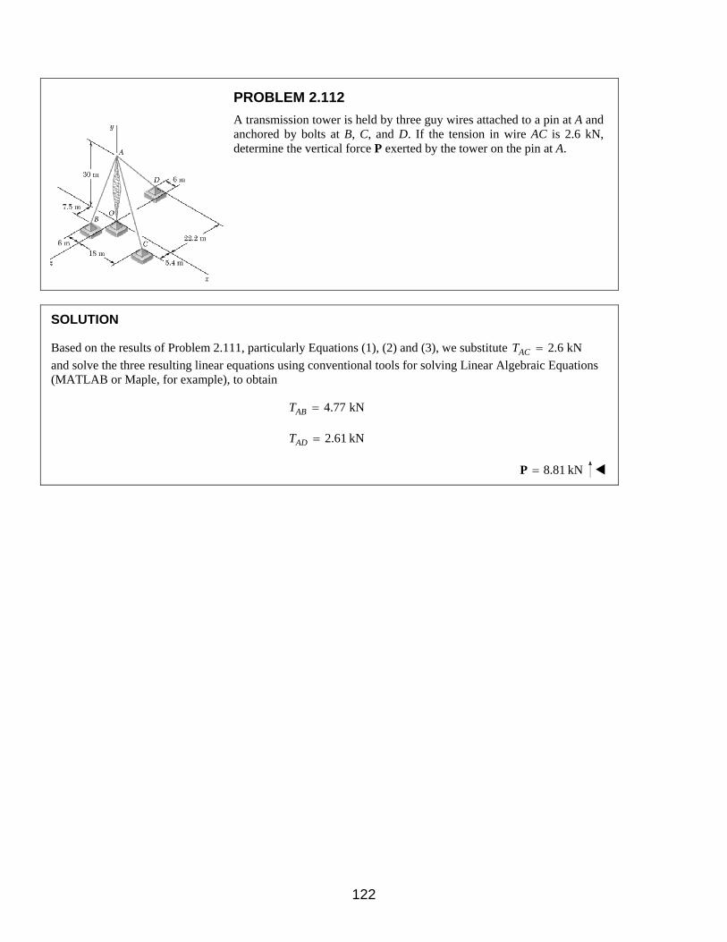
PROBLEM 2.112
A transmission tower is held by three guy wires attached to a pin at A and anchored by bolts at B, C, and D. If the tension in wire AC is 2.6 kN, determine the vertical force P exerted by the tower on the pin at A.
SOLUTION
Based on the results of Problem 2.111, particularly Equations (1), (2) and (3), we substitute 2.6 kNACT =
and solve the three resulting linear equations using conventional tools for solving Linear Algebraic Equations (MATLAB or Maple, for example), to obtain
4.77 kNABT =
2.61 kNADT =
8.81 kN=P
122

PROBLEM 2.113
A rectangular plate is supported by three cables as shown. Knowing that the tension in cable AC is 15 lb, determine the weight of the plate.
SOLUTION
The (vector) force in each cable can be written as the product of the (scalar) force and the unit vector along the cable. That is, with
( ) ( ) ( )32 in. 48 in. 36 in.AB = − +i j k
( ) ( ) ( )2 2 232 in. 48 in. 36 in. 68 in.AB = − + − + =
( ) ( ) ( )32 in. 48 in. 36 in.68 in.
ABAB AB AB
AB TT T
AB = = = − − + T i j kλ
( )0.4706 0.7059 0.5294AB ABT= − − +T i j k
and ( ) ( ) ( )45 in. 48 in. 36 in.AC = − +i j k
( ) ( ) ( )2 2 245 in. 48 in. 36 in. 75 in.AC = + − + =
( ) ( ) ( )45 in. 48 in. 36 in.75 in.
ACAC AC AC
AC TT T
AC = = = − + T i j kλ
( )0.60 0.64 0.48AC ACT= − +T i j k
Finally, ( ) ( ) ( )25 in. 48 in. 36 in.AD = − −i j k
( ) ( ) ( )2 2 225 in. 48 in. 36 in. 65 in.AD = + − + − =
123

PROBLEM 2.113 CONTINUED
( ) ( ) ( )25 in. 48 in. 36 in.65 in.
ADAD AD AD
AD TT T
AD = = = − − T i j kλ
( )0.3846 0.7385 0.5538AD ADT= − −T i j k
With ,W=W j at A we have:
0: 0AB AC AD WΣ = + + + =F T T T j
Equating the factors of i, j, and k to zero, we obtain the linear algebraic equations:
: 0.4706 0.60 0.3846 0AB AC ADT T T− + − =i (1)
: 0.7059 0.64 0.7385 0AB AC ADT T T W− − − + =j (2)
: 0.5294 0.48 0.5538 0AB AC ADT T T+ − =k (3)
In Equations (1), (2) and (3), set 15 lb,ACT = and, using conventional methods for solving Linear Algebraic Equations (MATLAB or Maple, for example), we obtain:
136.0 lbABT =
143.0 lbADT =
211 lbW =
124

PROBLEM 2.114
A rectangular plate is supported by three cables as shown. Knowing that the tension in cable AD is 120 lb, determine the weight of the plate.
SOLUTION
Based on the results of Problem 2.111, particularly Equations (1), (2) and (3), we substitute 120 lbADT = and
solve the three resulting linear equations using conventional tools for solving Linear Algebraic Equations (MATLAB or Maple, for example), to obtain
12.59 lbACT =
114.1 lbABT =
177.2 lbW =
125

PROBLEM 2.115
A horizontal circular plate having a mass of 28 kg is suspended as shown from three wires which are attached to a support D and form 30° angles with the vertical. Determine the tension in each wire.
SOLUTION
0: sin 30 sin 50 sin 30 cos 40x AD BDF T TΣ = − ° ° + ° °
sin 30 cos60 0CDT+ ° ° =
Dividing through by the factor sin 30° and evaluating the trigonometric functions gives
0.7660 0.7660 0.50 0AD BD CDT T T− + + = (1)
Similarly,
0: sin 30 cos50 sin 30 sin 40z AD BDF T TΣ = ° ° + ° °
sin 30 sin 60 0CDT− ° ° =
or 0.6428 0.6428 0.8660 0AD BD CDT T T+ − = (2)
From (1) 0.6527AD BD CDT T T= +
Substituting this into (2):
0.3573BD CDT T= (3)
Using ADT from above:
AD CDT T= (4)
Now,
0: cos30 cos30 cos30y AD BD CDF T T TΣ = − ° − ° − °
( )( )228 kg 9.81 m/s 0+ =
or 317.2 NAD BD CDT T T+ + =
126

PROBLEM 2.115 CONTINUED
Using (3) and (4), above:
0.3573 317.2 NCD CD CDT T T+ + =
Then: 135.1 NADT =
46.9 NBDT =
135.1 NCDT =
127
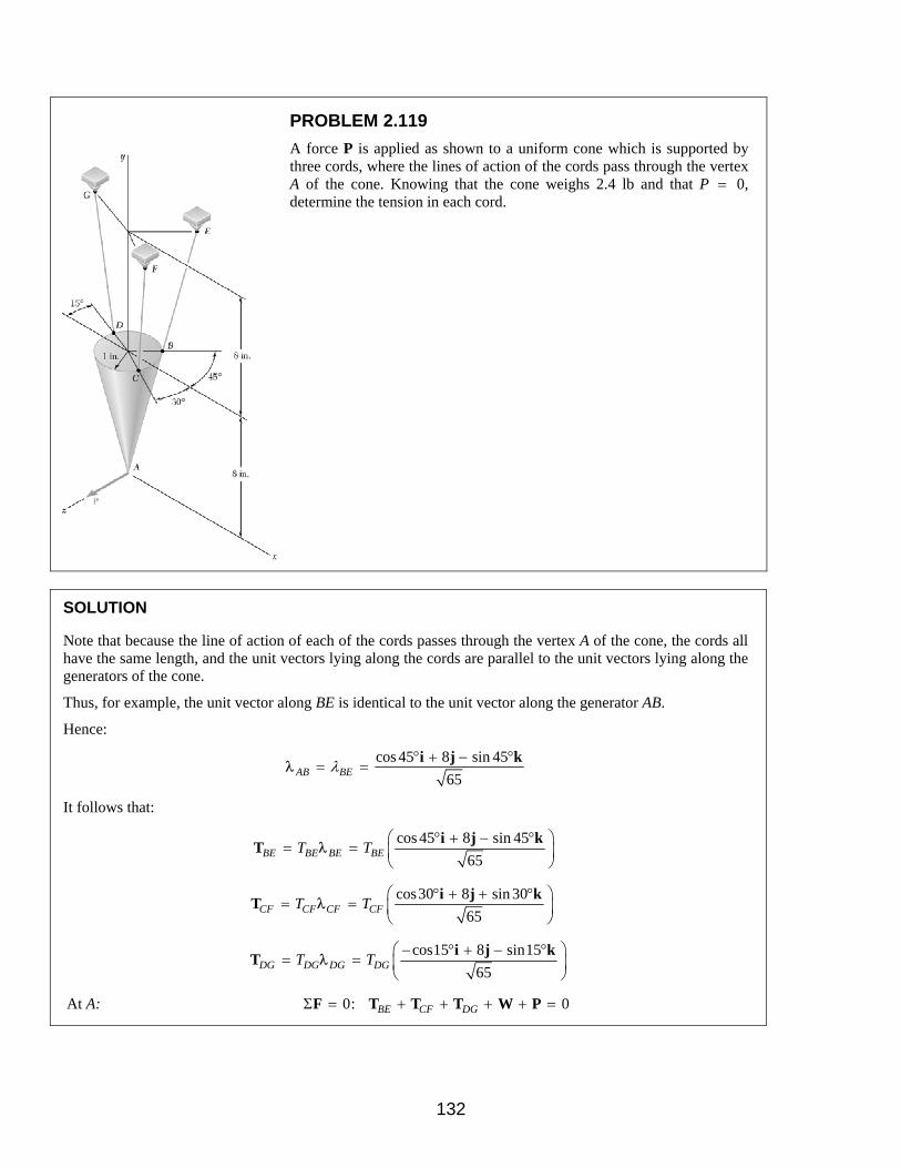
PROBLEM 2.119
A force P is applied as shown to a uniform cone which is supported by three cords, where the lines of action of the cords pass through the vertex A of the cone. Knowing that the cone weighs 2.4 lb and that P = 0, determine the tension in each cord.
SOLUTION
Note that because the line of action of each of the cords passes through the vertex A of the cone, the cords all have the same length, and the unit vectors lying along the cords are parallel to the unit vectors lying along the generators of the cone.
Thus, for example, the unit vector along BE is identical to the unit vector along the generator AB.
Hence:
cos 45 8 sin 45
65AB BEλ ° + − °
= =i j k
λ
It follows that:
cos 45 8 sin 45
65BE BE BE BET T
° + − ° = =
i j kT λ
cos30 8 sin 30
65CF CF CF CFT T
° + + ° = =
i j kT λ
cos15 8 sin15
65DG DG DG DGT T
− ° + − ° = =
i j kT λ
At A: 0: 0BE CF DGΣ = + + + + =F T T T W P
132

PROBLEM 2.119 CONTINUED
Then, isolating the factors if , , and i j k we obtain three algebraic equations:
: cos 45 cos30 cos15 065 65 65BE CF DGT T T
° + ° − ° =i
or cos 45 cos30 cos15 0BE CF DGT T T° + ° − ° = (1)
8 8 8
: 065 65 65
BE CF DGT T T W+ + − =j
or 2.4
65 0.3 658BE CF DGT T T+ + = = (2)
: sin 45 sin 30 sin15 065 65 65BE CF DGT T T
P− ° + ° − ° − =k
or sin 45 sin 30 sin15 65BE CF DGT T T P− ° + ° − ° = (3)
With 0,P = the tension in the cords can be found by solving the resulting Equations (1), (2), and (3) using conventional methods in Linear Algebra (elimination, matrix methods or iteration–with MATLAB or Maple, for example). We obtain
0.299 lbBET =
1.002 lbCFT =
1.117 lbDGT =
133

PROBLEM 2.120
A force P is applied as shown to a uniform cone which is supported by three cords, where the lines of action of the cords pass through the vertex A of the cone. Knowing that the cone weighs 2.4 lb and that P = 0.1 lb, determine the tension in each cord.
SOLUTION
See Problem 2.121 for the analysis leading to the linear algebraic Equations (1), (2), and (3) below:
cos 45 cos30 cos15 0BE CF DGT T T° + ° − ° = (1)
0.3 65BE CF DGT T T+ + = (2)
sin 45 sin 30 sin15 65BE CF DGT T T P− ° + ° − ° = (3)
With 0.1 lb,=P solving (1), (2), and (3), using conventional methods in Linear Algebra (elimination, matrix methods or iteration–with MATLAB or Maple, for example), we obtain
1.006 lbBET =
0.357 lbCFT =
1.056 lbDGT =
134

PROBLEM 2.121
Using two ropes and a roller chute, two workers are unloading a 200-kg cast-iron counterweight from a truck. Knowing that at the instant shown the counterweight is kept from moving and that the positions of points A, B, and C are, respectively, A(0, –0.5 m, 1 m), B(–0.6 m, 0.8 m, 0), and C(0.7 m, 0.9 m, 0), and assuming that no friction exists between the counterweight and the chute, determine the tension in each rope. (Hint: Since there is no friction, the force exerted by the chute on the counterweight must be perpendicular to the chute.)
SOLUTION
From the geometry of the chute:
( ) ( )2 0.8944 0.44725
NN= + = +N j k j k
As in Problem 2.11, for example, the force in each rope can be written as the product of the magnitude of the force and the unit vector along the cable. Thus, with
( ) ( ) ( )0.6 m 1.3 m 1 mAB = − + +i j k
( ) ( ) ( )2 2 20.6 m 1.3 m 1 m 1.764 mAB = − + + =
( ) ( ) ( )0.6 m 1.3 m 1 m1.764 m
ABAB AB AB
AB TT T
AB = = = − + + T i j kλ
( )0.3436 0.7444 0.5726AB ABT= − + +T i j k
and ( ) ( ) ( )0.7 m 1.4 m 1 mAC = + −i j k
( ) ( ) ( )2 2 20.7 m 1.4 m 1 m 1.8574 mAC = + + − =
( ) ( ) ( )0.7 m 1.4 m 1 m1.764 m
ACAC AC AC
AC TT T
AC = = = + − T i j kλ
( )0.3769 0.7537 0.5384AC ACT= + −T i j k
Then: 0: 0AB ACΣ = + + + =F N T T W
135
PROBLEM 2.121 CONTINUED
With ( )( )200 kg 9.81 m/s 1962 N,W = = and equating the factors of i, j,
and k to zero, we obtain the linear algebraic equations:
: 0.3436 0.3769 0AB ACT T− + =i (1)
: 0.7444 0.7537 0.8944 1962 0AB ACT T N+ + − =j (2)
: 0.5726 0.5384 0.4472 0AB ACT T N− − + =k (3)
Using conventional methods for solving Linear Algebraic Equations (elimination, MATLAB or Maple, for example), we obtain
1311 NN =
551 NABT =
503 NACT =
136

PROBLEM 2.122
Solve Problem 2.121 assuming that a third worker is exerting a force (180 N)= −P i on the counterweight.
Problem 2.121: Using two ropes and a roller chute, two workers are unloading a 200-kg cast-iron counterweight from a truck. Knowing that at the instant shown the counterweight is kept from moving and that the positions of points A, B, and C are, respectively, A(0, –0.5 m, 1 m), B(–0.6 m, 0.8 m, 0), and C(0.7 m, 0.9 m, 0), and assuming that no friction exists between the counterweight and the chute, determine the tension in each rope. (Hint: Since there is no friction, the force exerted by the chute on the counterweight must be perpendicular to the chute.)
SOLUTION
From the geometry of the chute:
( ) ( )2 0.8944 0.44725
NN= + = +N j k j k
As in Problem 2.11, for example, the force in each rope can be written as the product of the magnitude of the force and the unit vector along the cable. Thus, with
( ) ( ) ( )0.6 m 1.3 m 1 mAB = − + +i j k
( ) ( ) ( )2 2 20.6 m 1.3 m 1 m 1.764 mAB = − + + =
( ) ( ) ( )0.6 m 1.3 m 1 m1.764 m
ABAB AB AB
AB TT T
AB = = = − + + T i j kλ
( )0.3436 0.7444 0.5726AB ABT= − + +T i j k
and ( ) ( ) ( )0.7 m 1.4 m 1 mAC = + −i j k
( ) ( ) ( )2 2 20.7 m 1.4 m 1 m 1.8574 mAC = + + − =
( ) ( ) ( )0.7 m 1.4 m 1 m1.764 m
ACAC AC AC
AC TT T
AC = = = + − T i j kλ
( )0.3769 0.7537 0.5384AC ACT= + −T i j k
Then: 0: 0AB ACΣ = + + + + =F N T T P W
137
PROBLEM 2.122 CONTINUED
Where ( )180 N= −P i
and ( )( )2200 kg 9.81 m/s = − W j
( )1962 N= − j
Equating the factors of i, j, and k to zero, we obtain the linear equations:
: 0.3436 0.3769 180 0AB ACT T− + − =i
: 0.8944 0.7444 0.7537 1962 0AB ACN T T+ + − =j
: 0.4472 0.5726 0.5384 0AB ACN T T− − =k
Using conventional methods for solving Linear Algebraic Equations (elimination, MATLAB or Maple, for example), we obtain
1302 NN =
306 NABT =
756 NACT =
138

PROBLEM 2.123
A piece of machinery of weight W is temporarily supported by cables AB, AC, and ADE. Cable ADE is attached to the ring at A, passes over the pulley at D and back through the ring, and is attached to the support at E. Knowing that W = 320 lb, determine the tension in each cable. (Hint: The tension is the same in all portions of cable ADE.)
SOLUTION
The (vector) force in each cable can be written as the product of the (scalar) force and the unit vector along the cable. That is, with
( ) ( ) ( )9 ft 8 ft 12 ftAB = − + −i j k
( ) ( ) ( )2 2 29 ft 8 ft 12 ft 17 ftAB = − + + − =
( ) ( ) ( )9 ft 8 ft 12 ft17 ft
ABAB AB AB
AB TT T
AB = = = − + − T i j kλ
( )0.5294 0.4706 0.7059AB ABT= − + −T i j k
and
( ) ( ) ( )0 8 ft 6 ftAC = + +i j k
( ) ( ) ( )2 2 20 ft 8 ft 6 ft 10 ftAC = + + =
( ) ( ) ( )0 ft 8 ft 6 ft10 ft
ACAC AC AC
AC TT T
AC = = = + + T i j kλ
( )0.8 0.6AC ACT= +T j k
and
( ) ( ) ( )4 ft 8 ft 1 ftAD = + −i j k
( ) ( ) ( )2 2 24 ft 8 ft 1 ft 9 ftAD = + + − =
( ) ( ) ( )4 ft 8 ft 1 ft9 ftADE
AD AD ADEAD T
T TAD
= = = + − T i j kλ
( )0.4444 0.8889 0.1111AD ADET= + −T i j k
139

PROBLEM 2.123 CONTINUED
Finally,
( ) ( ) ( )8 ft 8 ft 4 ftAE = − + +i j k
( ) ( ) ( )2 2 28 ft 8 ft 4 ft 12 ftAE = − + + =
( ) ( ) ( )8 ft 8 ft 4 ft12 ft
ADEAE AE ADE
AE TT T
AE = = = − + + T i j kλ
( )0.6667 0.6667 0.3333AE ADET= − + +T i j k
With the weight of the machinery, ,W= −W j at A, we have:
0: 2 0AB AC AD WΣ = + + − =F T T T j
Equating the factors of , , and i j k to zero, we obtain the following linear algebraic equations:
( )0.5294 2 0.4444 0.6667 0AB ADE ADET T T− + − = (1)
( )0.4706 0.8 2 0.8889 0.6667 0AB AC ADE ADET T T T W+ + + − = (2)
( )0.7059 0.6 2 0.1111 0.3333 0AB AC ADE ADET T T T− + − + = (3)
Knowing that 320 lb,W = we can solve Equations (1), (2) and (3) using conventional methods for solving
Linear Algebraic Equations (elimination, matrix methods via MATLAB or Maple, for example) to obtain
46.5 lbABT =
34.2 lbACT =
110.8 lbADET =
140

PROBLEM 2.124
A piece of machinery of weight W is temporarily supported by cables AB, AC, and ADE. Cable ADE is attached to the ring at A, passes over the pulley at D and back through the ring, and is attached to the support at E. Knowing that the tension in cable AB is 68 lb, determine (a) the tension in AC, (b) the tension in ADE, (c) the weight W. (Hint: The tension is the same in all portions of cable ADE.)
SOLUTION
See Problem 2.123 for the analysis leading to the linear algebraic Equations (1), (2), and (3), below:
( )0.5294 2 0.4444 0.6667 0AB ADE ADET T T− + − = (1)
( )0.4706 0.8 2 0.8889 0.6667 0AB AC ADE ADET T T T W+ + + − = (2)
( )0.7059 0.6 2 0.1111 0.3333 0AB AC ADE ADET T T T− + − + = (3)
Knowing that the tension in cable AB is 68 lb, we can solve Equations (1), (2) and (3) using conventional
methods for solving Linear Algebraic Equations (elimination, matrix methods via MATLAB or Maple, for example) to obtain
(a) 50.0 lbACT =
(b) 162.0 lbAET =
(c) 468 lbW =
141

PROBLEM 2.128
Solve Problem 2.127 assuming 550y = mm.
Problem 2.127: Collars A and B are connected by a 1-m-long wire and can slide freely on frictionless rods. If a force (680 N)=P j is applied at
A, determine (a) the tension in the wire when 300y = mm, (b) the
magnitude of the force Q required to maintain the equilibrium of the system.
SOLUTION
From the analysis of Problem 2.127, particularly the results:
2 2 20.84 my z+ =
680 NABT
y=
680 NQ z
y=
With 550 mm 0.55 m,y = = we obtain:
( )22 20.84 m 0.55 m
0.733 m
= −
∴ =
z
z
and
(a) 680 N
1236.4 N0.55ABT = =
or 1.236 kNABT =
and
(b) ( )1236 0.866 N 906 N= =Q
or 0.906 kNQ =
147

PROBLEM 2.129
Member BD exerts on member ABC a force P directed along line BD. Knowing that P must have a 300-lb horizontal component, determine (a) the magnitude of the force P, (b) its vertical component.
SOLUTION
(a) sin 35 3001bP ° =
300 lb
sin 35P =
°
523 lbP =
(b) Vertical Component
cos35vP P= °
( )523 lb cos35= °
428 lb=vP
148
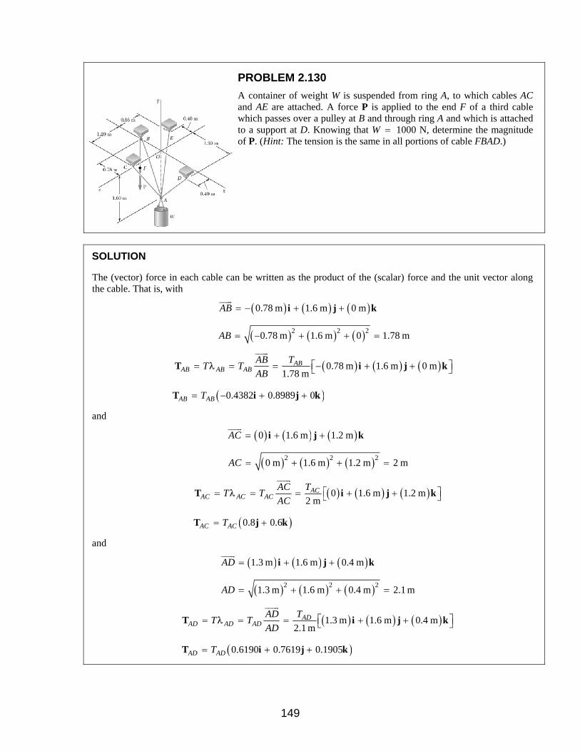
PROBLEM 2.130
A container of weight W is suspended from ring A, to which cables AC and AE are attached. A force P is applied to the end F of a third cable which passes over a pulley at B and through ring A and which is attached to a support at D. Knowing that W = 1000 N, determine the magnitude of P. (Hint: The tension is the same in all portions of cable FBAD.)
SOLUTION
The (vector) force in each cable can be written as the product of the (scalar) force and the unit vector along the cable. That is, with
( ) ( ) ( )0.78 m 1.6 m 0 mAB = − + +i j k
( ) ( ) ( )2 2 20.78 m 1.6 m 0 1.78 mAB = − + + =
( ) ( ) ( )0.78 m 1.6 m 0 m1.78 m
ABAB AB AB
AB TT T
AB = = = − + + T i j kλ
( )0.4382 0.8989 0AB ABT= − + +T i j k
and
( ) ( ) ( )0 1.6 m 1.2 mAC = + +i j k
( ) ( ) ( )2 2 20 m 1.6 m 1.2 m 2 mAC = + + =
( ) ( ) ( )0 1.6 m 1.2 m2 m
ACAC AC AC
AC TT T
AC = = = + + T i j kλ
( )0.8 0.6AC ACT= +T j k
and
( ) ( ) ( )1.3 m 1.6 m 0.4 mAD = + +i j k
( ) ( ) ( )2 2 21.3 m 1.6 m 0.4 m 2.1 mAD = + + =
( ) ( ) ( )1.3 m 1.6 m 0.4 m2.1 m
ADAD AD AD
AD TT T
AD = = = + + T i j kλ
( )0.6190 0.7619 0.1905AD ADT= + +T i j k
149
PROBLEM 2.130 CONTINUED
Finally,
( ) ( ) ( )0.4 m 1.6 m 0.86 mAE = − + −i j k
( ) ( ) ( )2 2 20.4 m 1.6 m 0.86 m 1.86 mAE = − + + − =
( ) ( ) ( )0.4 m 1.6 m 0.86 m1.86 m
AEAE AE AE
AE TT T
AE = = = − + − T i j kλ
( )0.2151 0.8602 0.4624AE AET= − + −T i j k
With the weight of the container ,W= −W j at A we have:
0: 0AB AC AD WΣ = + + − =F T T T j
Equating the factors of , , and i j k to zero, we obtain the following linear algebraic equations:
0.4382 0.6190 0.2151 0AB AD AET T T− + − = (1)
0.8989 0.8 0.7619 0.8602 0AB AC AD AET T T T W+ + + − = (2)
0.6 0.1905 0.4624 0AC AD AET T T+ − = (3)
Knowing that 1000 NW = and that because of the pulley system at B ,AB ADT T P= = where P is the
externally applied (unknown) force, we can solve the system of linear equations (1), (2) and (3) uniquely for P.
378 NP =
150

PROBLEM 2.131
A container of weight W is suspended from ring A, to which cables AC and AE are attached. A force P is applied to the end F of a third cable which passes over a pulley at B and through ring A and which is attached to a support at D. Knowing that the tension in cable AC is 150 N, determine (a) the magnitude of the force P, (b) the weight W of the container. (Hint: The tension is the same in all portions of cable FBAD.)
SOLUTION
Here, as in Problem 2.130, the support of the container consists of the four cables AE, AC, AD, and AB, with the condition that the force in cables AB and AD is equal to the externally applied force P. Thus, with the condition
AB ADT T P= =
and using the linear algebraic equations of Problem 2.131 with 150 N,ACT = we obtain
(a) 454 NP =
(b) 1202 NW =
151

PROBLEM 2.125
A container of weight W is suspended from ring A. Cable BAC passes through the ring and is attached to fixed supports at B and C. Two forces
P=P i and Q=Q k are applied to the ring to maintain the container is
the position shown. Knowing that 1200W = N, determine P and Q. (Hint: The tension is the same in both portions of cable BAC.)
SOLUTION
The (vector) force in each cable can be written as the product of the (scalar) force and the unit vector along the cable. That is, with
( ) ( ) ( )0.48 m 0.72 m 0.16 mAB = − + −i j k
( ) ( ) ( )2 2 20.48 m 0.72 m 0.16 m 0.88 mAB = − + + − =
( ) ( ) ( )0.48 m 0.72 m 0.16 m0.88 m
ABAB AB AB
AB TT T
AB = = = − + − T i j kλ
( )0.5455 0.8182 0.1818AB ABT= − + −T i j k
and
( ) ( ) ( )0.24 m 0.72 m 0.13 mAC = + −i j k
( ) ( ) ( )2 2 20.24 m 0.72 m 0.13 m 0.77 mAC = + − =
( ) ( ) ( )0.24 m 0.72 m 0.13 m0.77 m
ACAC AC AC
AC TT T
AC = = = + − T i j kλ
( )0.3177 0.9351 0.1688AC ACT= + −T i j k
At A: 0: 0AB ACΣ = + + + + =F T T P Q W
142

PROBLEM 2.125 CONTINUED
Noting that AB ACT T= because of the ring A, we equate the factors of
, , and i j k to zero to obtain the linear algebraic equations:
( ): 0.5455 0.3177 0T P− + + =i
or 0.2338P T=
( ): 0.8182 0.9351 0T W+ − =j
or 1.7532W T=
( ): 0.1818 0.1688 0T Q− − + =k
or 0.356Q T=
With 1200 N:W =
1200 N684.5 N
1.7532T = =
160.0 NP =
240 NQ =
143

PROBLEM 2.126
For the system of Problem 2.125, determine W and P knowing that 160Q = N.
Problem 2.125: A container of weight W is suspended from ring A. Cable BAC passes through the ring and is attached to fixed supports at B and C. Two forces P=P i and Q=Q k are applied to the ring to
maintain the container is the position shown. Knowing that 1200W = N, determine P and Q. (Hint: The tension is the same in both portions of cable BAC.)
SOLUTION
Based on the results of Problem 2.125, particularly the three equations relating P, Q, W, and T we substitute 160 NQ = to obtain
160 N456.3 N
0.3506T = =
800 NW =
107.0 NP =
144

PROBLEM 2.127
Collars A and B are connected by a 1-m-long wire and can slide freely on frictionless rods. If a force (680 N)=P j is applied at A, determine
(a) the tension in the wire when 300y = mm, (b) the magnitude of the
force Q required to maintain the equilibrium of the system.
SOLUTION
Free-Body Diagrams of collars
For both Problems 2.127 and 2.128:
( )2 2 2 2AB x y z= + +
Here ( ) ( )2 2 2 21 m 0.40 m y z= + +
or 2 2 20.84 my z+ =
Thus, with y given, z is determined.
Now
( )10.40 m 0.4
1 mABAB
y z y zAB
= = − + = − +i j k i k kλ
Where y and z are in units of meters, m.
From the F.B. Diagram of collar A:
0: 0x z AB ABN N P TΣ = + + + =F i k j λ
Setting the jcoefficient to zero gives:
0ABP yT− =
With 680 N,P =
680 NABT
y=
Now, from the free body diagram of collar B:
0: 0x y AB ABN N Q TΣ = + + − =F i j k λ
145
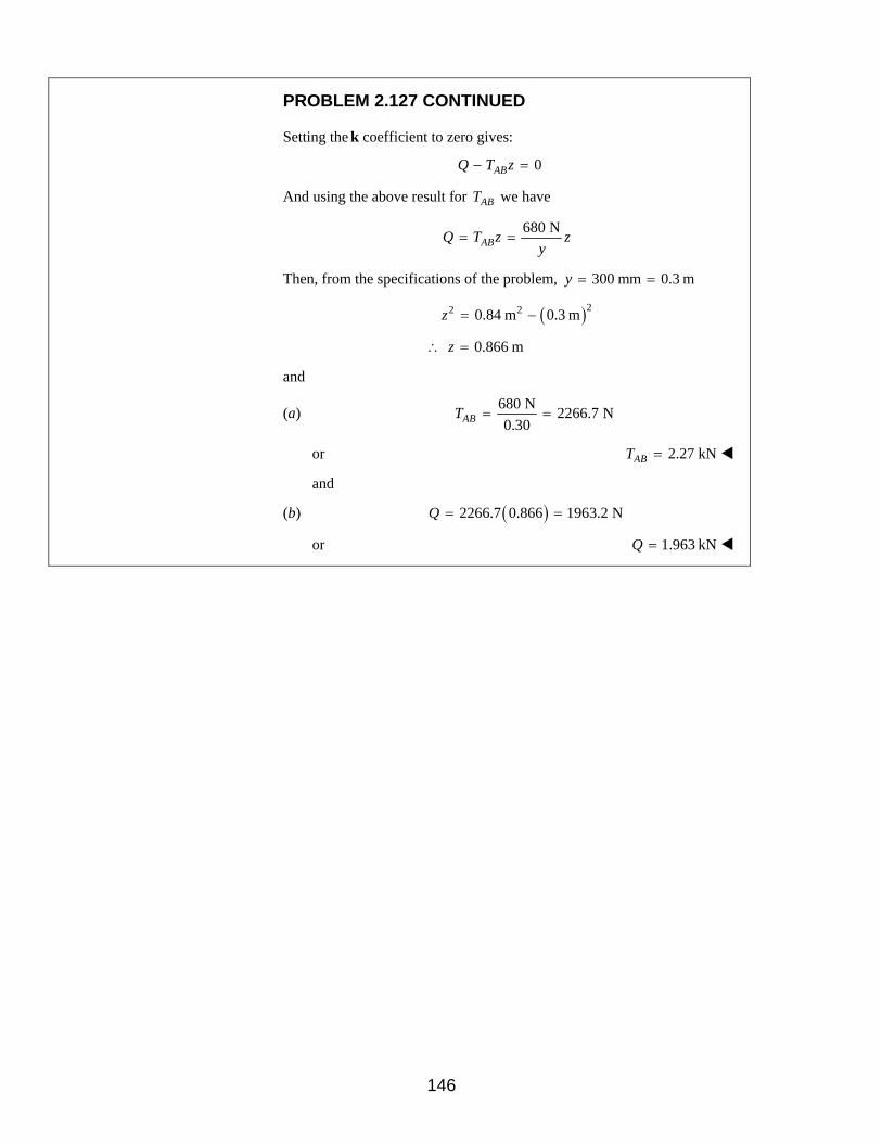
PROBLEM 2.127 CONTINUED
Setting the k coefficient to zero gives:
0ABQ T z− =
And using the above result for ABT we have
680 NABQ T z z
y= =
Then, from the specifications of the problem, 300 mm 0.3 my = =
( )22 20.84 m 0.3 m= −z
0.866 m∴ =z
and
(a) 680 N
2266.7 N0.30ABT = =
or 2.27 kNABT =
and
(b) ( )2266.7 0.866 1963.2 NQ = =
or 1.963 kNQ =
146

PROBLEM 2.116
A transmission tower is held by three guy wires attached to a pin at A and anchored by bolts at B, C, and D. Knowing that the tower exerts on the pin at A an upward vertical force of 8 kN, determine the tension in each wire.
SOLUTION
From the solutions of 2.111 and 2.112:
0.5409ABT P=
0.295ACT P=
0.2959ADT P=
Using 8 kN:P =
4.33 kNABT =
2.36 kNACT =
2.37 kNADT =
128

PROBLEM 2.117
For the rectangular plate of Problems 2.113 and 2.114, determine the tension in each of the three cables knowing that the weight of the plate is 180 lb.
SOLUTION
From the solutions of 2.113 and 2.114:
0.6440ABT P=
0.0709ACT P=
0.6771ADT P=
Using 180 lb:P =
115.9 lbABT =
12.76 lbACT =
121.9 lbADT =
129

PROBLEM 2.118
For the cone of Problem 2.110, determine the range of values of P for which cord DG is taut if P is directed in the –x direction.
SOLUTION
From the solutions to Problems 2.109 and 2.110, have
0.2 65BE CF DGT T T+ + = (2 )′
sin 45 sin 30 sin15 0BE CF DGT T T− ° + ° − ° = (3)
cos 45 cos30 cos15 65 0BE CF DGT T T P° + ° − ° − = (1 )′
Applying the method of elimination to obtain a desired result:
Multiplying (2 )′ by sin 45° and adding the result to (3):
( ) ( )sin 45 sin 30 sin 45 sin15 0.2 65 sin 45CF DGT T° + ° + ° − ° = °
or 0.9445 0.3714CF DGT T= − (4)
Multiplying (2 )′ by sin 30° and subtracting (3) from the result:
( ) ( )sin 30 sin 45 sin 30 sin15 0.2 65 sin 30BE DGT T° + ° + ° + ° = °
or 0.6679 0.6286BE DGT T= − (5)
130

PROBLEM 2.118 CONTINUED
Substituting (4) and (5) into (1)′ :
1.2903 1.7321 65 0DGT P− − =
DGT∴ is taut for 1.2903
lb65
P <
or 0.16000 lbP≤ <
131

PROBLEM 2.132
Two cables tied together at C are loaded as shown. Knowing that Q = 60 lb, determine the tension (a) in cable AC, (b) in cable BC.
SOLUTION
0: cos30 0y CAF T QΣ = − ° =
With 60 lbQ =
(a) ( )( )60 lb 0.866CAT =
52.0 lbCAT =
(b) 0: sin 30 0x CBF P T QΣ = − − ° =
With 75 lbP =
( )( )75 lb 60 lb 0.50CBT = −
or 45.0 lbCBT =
152

PROBLEM 2.133
Two cables tied together at C are loaded as shown. Determine the range of values of Q for which the tension will not exceed 60 lb in either cable.
SOLUTION
Have 0: cos30 0x CAF T QΣ = − ° =
or 0.8660 QCAT =
Then for 60 lbCAT ≤
0.8660 60 lbQ <
or 69.3 lbQ ≤
From 0: sin 30y CBF T P QΣ = = − °
or 75 lb 0.50CBT Q= −
For 60 lbCBT ≤
75 lb 0.50 60 lbQ− ≤
or 0.50 15 lbQ ≥
Thus, 30 lbQ ≥
Therefore, 30.0 69.3 lbQ≤ ≤
153

PROBLEM 2.134
A welded connection is in equilibrium under the action of the four forces shown. Knowing that 8 kNAF = and 16 kN,BF = determine the magnitudes of the other two forces.
SOLUTION
Free-Body Diagram of Connection
3 30: 0
5 5x B C AF F F FΣ = − − =
With 8 kN, 16 kNA BF F= =
( ) ( )4 416 kN 8 kN
5 5CF = −
6.40 kNCF =
3 30: 0
5 5y D B AF F F FΣ = − + − =
With AF and BF as above:
( ) ( )3 316 kN 8 kN
5 5DF = −
4.80 kNDF =
154

PROBLEM 2.135
A welded connection is in equilibrium under the action of the four forces shown. Knowing that 5 kNAF = and 6 kN,DF = determine the magnitudes of the other two forces.
SOLUTION
Free-Body Diagram of Connection
3 30: 0
5 5y D A BF F F FΣ = − − + =
or 3
5B D AF F F= +
With 5 kN, 8 kNA DF F= =
( )5 36 kN 5 kN
3 5BF = +
15.00 kNBF =
4 40: 0
5 5x C B AF F F FΣ = − + − =
( )4
5C B AF F F= −
( )415 kN 5 kN
5= −
8.00 kNCF =
155

PROBLEM 2.136
Collar A is connected as shown to a 50-lb load and can slide on a frictionless horizontal rod. Determine the magnitude of the force P required to maintain the equilibrium of the collar when (a) x = 4.5 in., (b) x = 15 in.
SOLUTION
Free-Body Diagram of Collar
(a) Triangle Proportions
( )4.50: 50 lb 0
20.5xF PΣ = − + =
or 10.98 lbP =
(b) Triangle Proportions
( )150: 50 lb 0
25xF PΣ = − + =
or 30.0 lbP =
156

PROBLEM 2.137
Collar A is connected as shown to a 50-lb load and can slide on a frictionless horizontal rod. Determine the distance x for which the collar is in equilibrium when P = 48 lb.
SOLUTION
Free-Body Diagram of Collar
Triangle Proportions
Hence: 2
ˆ500: 48 0
ˆ400x
xF
xΣ = − + =
+
or 248ˆ ˆ400
50x x= +
( )2 2ˆ ˆ0.92 lb 400x x= +
2 2ˆ 4737.7 inx =
ˆ 68.6 in.x =
157

PROBLEM 2.138
A frame ABC is supported in part by cable DBE which passes through a frictionless ring at B. Knowing that the tension in the cable is 385 N, determine the components of the force exerted by the cable on the support at D.
SOLUTION
The force in cable DB can be written as the product of the magnitude of the force and the unit vector along the cable. That is, with
( ) ( ) ( )480 mm 510 mm 320 mmDB = − +i j k
( ) ( ) ( )2 2 2480 510 320 770 mmDB = + + =
( ) ( ) ( )385 N480 mm 510 mm 320 mm
770 mmDBDB
F FDB
= = = − + F i j kλ
( ) ( ) ( )240 N 255 N 160 N= − +F i j k
240 N, 255 N, 160.0 Nx y zF F F= + = − = +
158

PROBLEM 2.139
A frame ABC is supported in part by cable DBE which passes through a frictionless ring at B. Determine the magnitude and direction of the resultant of the forces exerted by the cable at B knowing that the tension in the cable is 385 N.
SOLUTION
The force in each cable can be written as the product of the magnitude of the force and the unit vector along the cable. That is, with
( ) ( ) ( )0.48 m 0.51 m 0.32 mBD = − + −i j k
( ) ( ) ( )2 2 20.48 m 0.51 m 0.32 m 0.77 mBD = − + + − =
( ) ( ) ( )0.48 m 0.51 m 0.32 m0.77 m
BDBD BD BD
BD TT T
BD = = = − + − T i j kλ
( )0.6234 0.6623 0.4156BD BDT= − + −T i j k
and
( ) ( ) ( )0.27 m 0.40 m 0.6 mBE = − + −i j k
( ) ( ) ( )2 2 20.27 m 0.40 m 0.6 m 0.770 mBE = − + + − =
( ) ( ) ( )0.26 m 0.40 m 0.6 m0.770 m
BEBE BE BE
BD TT T
BD = = = − + − T i j kλ
( )0.3506 0.5195 0.7792BE BET= − + −T i j k
Now, because of the frictionless ring at B, 385 NBE BDT T= = and the force on the support due to the two cables is
( )385 N 0.6234 0.6623 0.4156 0.3506 0.5195 0.7792= − + − − + −F i j k i j k
( ) ( ) ( )375 N 455 N 460 N= − + −i j k
159

PROBLEM 2.139 CONTINUED
The magnitude of the resultant is
( ) ( ) ( )2 2 22 2 2 375 N 455 N 460 N 747.83 Nx y zF F F F= + + = − + + − =
or 748 NF =
The direction of this force is:
1 375cos
747.83xθ− −
= or 120.1xθ = °
1 455cos
747.83yθ−= or 52.5yθ = °
1 460cos
747.83zθ− −
= or 128.0zθ = °
160
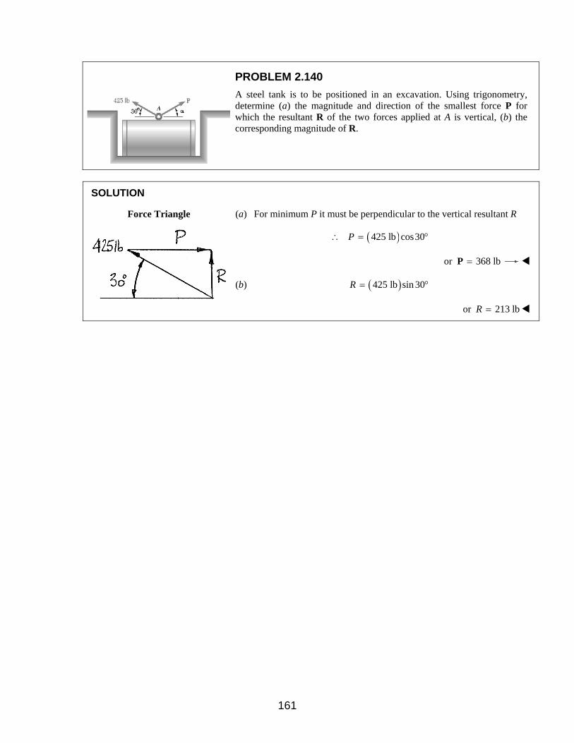
PROBLEM 2.140
A steel tank is to be positioned in an excavation. Using trigonometry, determine (a) the magnitude and direction of the smallest force P for which the resultant R of the two forces applied at A is vertical, (b) the corresponding magnitude of R.
SOLUTION
Force Triangle
(a) For minimum P it must be perpendicular to the vertical resultant R
( ) 425 lb cos30P∴ = °
or 368 lb=P
(b) ( )425 lb sin 30R = °
or 213 lbR =
161