beeps, buzzers and...
TRANSCRIPT

Beeps, Buzzers and Alarms The Hemodialysis machine
Madhukar Misra MD Professor of Medicine
University of Missouri Columbia

The systems Approach
● The HD machine cannot be isolated from the rest
● It is a part of an assembly ■ The HD machine ■ The extracorporeal circuit ■ The dialyzer ■ The water treatment system ■ Dialysate concentrate supply ■ The data network
Polaschegg HD, Contrib Nephrol 2002.137;227-235

Is there an Ideal Hemodialysis Machine?
● The ‘ideal’ machine does not exist and will never exist
● The utilitarian philosopher’s ‘ideal’: ■ Achieve minimum dialysis dose ■ Achieve accuracy in controlled values ■ Achieve quality while controlling costs
● Machines are smarter in sensing/measuring/balancing
● User errors are common.
Polaschegg HD, Contrib Nephrol 2002.137;227-235

Machine malfunction is rare
Hemodialysis is prone to user errors
■ Poor fixation of cannulas
■ Incorrect setting of alarm limits and control values

Failure to follow Protocol is common
PennsylvaniaPatientSafetyAuthority.2010.7(3);87-96
Event type Number % of total events, N=526
Medication error 150 28.5
Failure to follow protocol 68 12.9
Lab/Blood bank related 52 9.9
Procedure complication 45 8.6
Needle disconnection 32 6.1
Needle infiltration 32 6.1
Equipment failure 25 4.8
System Clotting 23 4.4

Fundamental Requirements of Hemodialysis Instruments
Ø Propel blood & dialysate
Ø Provide life sustaining “dose”
Ø Anticoagulation
Ø Maintain body temperature
Ø Prime, rinseback, and rapid hydration
Ø Add meds/draw blood
Ø Blood loss to environment
Ø Hemolysis
Ø Air embolism
Ø Excessive or inadequate fluid removal
Ø Infection
Ø Acute or chronic toxicity
Ø Anaphylaxis
Practical Aspects Hazard Prevention

Heparin
Saline
Blood pump
Venous Air trap
Post-pump (positive) pressure
Pre-pump (negative) pressure Injection
site
Injection site
Air detector
Clamp
Pressure
Pressure
Flow meter
RO pump
RO filter
Carbon filters
Drain line
Pyrogen filter
Temp
Conductivity
Mixing Chamber
Bicarb
Acid
Balancing Chambers
Deaeration Chamber
Dialysate pump
Heater

Blood Circuit
Dialysate Circuit
Inflow pressure Conductivity
Outflow pressure Temperature
Air Detector Hemoglobin
Beeps, Buzzers and Alarms

Blood Circuit Monitors
AdaptedfromHandbookofDialysisTherapy.NissensonandFine.4thedi;on,SaundersElsevierPubs.
Safety monitors Ø Can not ‘prevent’ adverse events Ø Can only ‘detect and mitigate’ the potential harm

Know your machine! Patient safety should never be compromised
• Alarms represent potential malfunction in the system • NEVER alter alarm sensitivity and range • Discourage Alarm disarming • Alarms should be visible at minimum of 2 m and
easily audible (70 dB) • All blood alarms should isolate the patient
• Shut off the blood pump • Clamp the venous return • Stop UF
No Alarm is Fail-Safe
MisraM.ThebasicsofHDequipment.HemodialysisInternational2005;9:30–36

The blood side
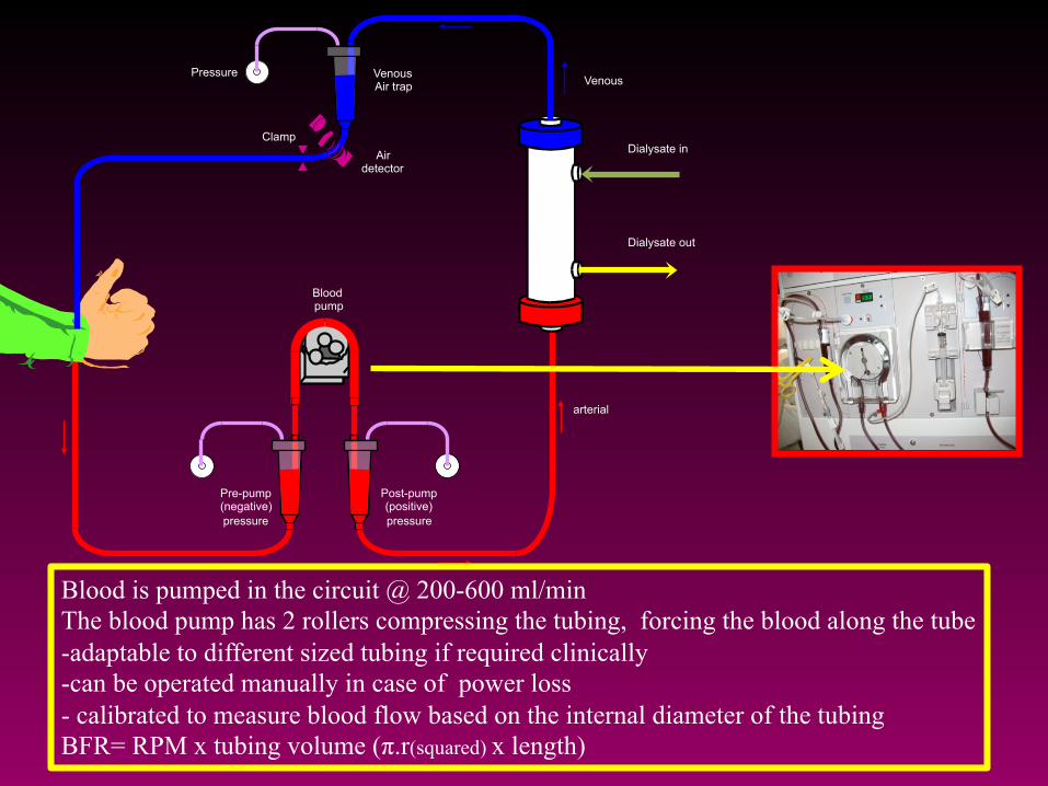
Blood pump
Venous Air trap
Post-pump (positive) pressure
Pre-pump (negative) pressure
Air detector
Clamp
Pressure
Dialysate in
Dialysate out
Venous
arterial
Blood is pumped in the circuit @ 200-600 ml/min The blood pump has 2 rollers compressing the tubing, forcing the blood along the tube -adaptable to different sized tubing if required clinically -can be operated manually in case of power loss - calibrated to measure blood flow based on the internal diameter of the tubing BFR= RPM x tubing volume (π.r(squared) x length)

Possible sites for Air entry and blood loss
+++++++++++++++++++++++++++++++++++++++
------------------------
§ Arterial needle/Pre pump tubing
§ Open venous catheter § Empty bags/ infusion set

Blood pump
Post-pump (positive) pressure
Pre-pump (negative) pressure
arterial
Excessively Negative Arterial pressure
• Low BP
• Catheter /needle malposition
• Kink/Clot
• Suction/spasm of vessel wall
• Stenosis in AVF
• Long small bore needles

Heparin
Saline
Blood pump
Venous Air trap
Post-pump (positive) pressure
Pre-pump (negative) pressure Injection
site
Injection site
Air detector
Clamp
Pressure
Low negative arterial Pressure
Line separation
Unclamping of saline infusion line
Blood pump tearing the pumping segment

Blood pump
Venous Air trap
Post-pump (positive) pressure
Pre-pump (negative) pressure
Air detector
Clamp
Pressure
The Venous Chamber
1. Allows for determining Positive pressure on the blood access site
2. Allows for separation of air bubbles (excessive air, when present, may still enter the patient)

Blood pump
Venous Air trap
Post-pump (positive) pressure
Pre-pump (negative) pressure
Pressure
Low venous pressure alarm
High venous pressure alarm
• High Qb, narrow needle
• Clot in the venous drip chamber, needle, venous limb
• Spasm of venous limb of AV access
• Kink in the venous return line
• Needle malposition
Low blood flow upstream
Disconnection downstream

Ø 2 hours into HD, a patient c/o feeling weak. He has been c/o cramps for last 2 weeks.
Ø BP is 110/70 mm Hg (initial BP 150/95 mm Hg). HR 75/min, regular. Qb 500 ml/min. Qd 800 ml/min.
Ø Nurse checks HD machine, turns UF off, reduces blood flow to 200 ml/min
Ø HD is resumed
Question

Question (contd.)
Ø 2 minutes later, patient now c/o feeling cold, and restless. SBP 80 mm Hg.
Ø IV saline (0.9%) is started and foot end is raised. Additional blankets are provided. No machine alarms. HD is continued.
Ø Patient suddenly codes and CPR is started. Ø Nurse notices blood pool below the dialysis chair.
Blankets are removed. Blood is being pumped on to the floor via the venous needle.

Why did the venous alarm not sound?
What happened? Venous Needle Dislodgement
Safety is the freedom from unacceptable risk International Standard Organization 2007

A. Intra access pressure B. Needle/Cannula geometry C. Blood flow rate and viscosity D. All of the above
The venous pressure reading during HD is determined by

Venous Pressure Monitor reading
Height difference
Intra-access pressure
Venous monitor: Pressures and Heights
Ribitsch W. et al Seminars in Dialysis 2013
Ø The fistula pressure
Ø Qb, viscosity
Ø Flow resistance
Ø The height difference between AVF and the level in the venous chamber

In absence of blood flow
Ø Venous pressure reading = Intra access pressure Ø (when corrected for height difference between the access
and the pressure monitor)
v When needle slips out from access but remains at the same height, the venous pressure will decrease by the amount of the access pressure

q Venous pressure
• Intra-access pressure • Qb • Needle length/gauge/
thickness • Blood viscosity With narrow gauge needles and high Qb,
the relatively higher flow resistance within needle may prevent the venous
pressure to fall low enough to set off the alarm
Needles may contribute significantly to venous pressure readings

The lower limit of the venous pressure alarms are usually
set 30-40 mm below the access pressure
For the alarm to sound after VND, the pressure drop should exceed the
pressure difference between the actual venous pressure and the lower alarm
limit venous sensor

Ribitsch W. et al Seminars in Dialysis 2013
Graft (%) Fistula (%)
Over 90% AVG have access pressures >40 Only 30% AVF have access pressures >40
Lower detection limit of venous sensor
Fistulae have much lower pressure than grafts AVG 60 mm Hg ; AVF 32 mm Hg
It may be difficult to detect VND in AVFs

Risk factors associated with venous needle dislodgement
q Never set wide alarm windows for VP monitors
q Check access and tubing when alarms are reset
q Secure tubing connections and cannula position
q Avoid covering access sites

UK Renal unit Survey [Clinical Directors and Lead renal nurses]
§ Estimated prevalence/incidence of dislodgement § UK ~ 100/year (0-4 episodes/unit/year) § ~ 1/100,000 haemodialysis sessions
§ Severity § 1 death (0.6%) § 6.4% Moderate/Severe harm (e.g. hospitalization) § 93.0% No/Mild Harm
In just 5-7 minutes a patient on HD can lose 40% of blood Volume from a Venous Needle dislodgement
Loss of 15-20% of blood volume over half an hour will cause death of a person with impaired sympathetic reflexes. Guyton AC. 1991
Many nurses and doctors are unaware of the limitations of venous alarms

Vascular Access Monitoring To Prevent Blood Leakage
Gutter of drainage with blood sensor stopping blood pump
Vascular access monitoring with blood sensor connected via Bluetooth to HD monitor

Blood pump
Venous Air trap
Post-pump (positive) pressure
Pre-pump (negative) pressure
Air detector
Clamp
Pressure
• Ultrasonic
• Located on return line
• Alarm activated by air in blood/saline or both
UABD lies below the bubble trap to prevent air passage
• Incidence of major air embolus 1:2000 treatments • Usual volume required= 60-125 ml, esp. if injected rapidly
Lodi CA et al CJASN 5: 2004 –2017, 2010

Air Microbubbles are found in Hemodialysis Patients
Microscopic finding of microbubbles of air ( arrow) in pulmonary capillary; also, increased fibrosis of
tissue (red areas).
Microscopic finding of microbubbles of air in the brain (arrow).
Stegmayr B et al ASAIO Journal 2012; 58:177–179

Microemboli in brain in HD
Stegmayr et al. Hemodialysis International. 2(2);168-172:2016
Fibrin around air bubbles indicating clot formation
(antifibrinogen antibody staining)

Microemboli can enter into HD patients without triggering alarms
Forsberg U et al, Nephrol Dial Transplant 2010; 25: 2691–2695
§ 54 HD patients (16 CVC, 38 AVF)
§ Microemboli measured at AVF and Common Carotid artery before and during HD
§ Significant increase in microembolic signals detected at both sites during HD

Preventing air embolism

Handling Measure Negative Pressure Connections Connection between needle/CVC and arterial
tube closed Heparin tube connector closed Arterial Pressure tube tightly applied
Priming of EC circuit More volume is better (1.5l) Turn and knock on steam sterilized dialyzers
Blood Pump Qb <200 ml/min
Venous air trap Avoid low fluid level
Syringes Take care to empty air
Dialyzer Wet stored dialyzer preferred; careful connection to avoid air contamination
Air trap and dialysis device Each brand has different conditions. Check with provider
EC components (tubing sets, dialyzers) Each brand has different conditions. Check with provider

The Dialysate pathway

Heparin
Saline
Blood pump
Venous Air trap
Post-pump (positive) pressure
Pre-pump (negative) pressure Injection
site
Injection site
Air detector
Clamp
Pressure
Pressure
Flow meter
RO pump
RO filter
Carbon filters
Drain line
Pyrogen filter
Temp
Conductivity
Mixing Chamber
Bicarb
Acid
Balancing Chambers
Deaeration Chamber
Dialysate pump
Heater

Simplified Fluid Pathway
AdaptedfromHandbookofDialysisTherapy.NissensonandFine.4thedi;on,SaundersElsevierPubs.

The three stream method of preparing a bicarbonate
based dialysate
Dual concentrate proportioning machine
Adapted from Bosch JP and Stein JH, eds. Hemodialysis: High Efficiency Treatments, Churchill Livingstone, New York NY. 1993;9-26
Organic acid Glacial acetic acid/sodium diacetate/
citric acid

45 y/ white male on HD X 4 y. Cause of ESRD: Chronic GN
Pre Labs (midweek): K 5, Na 138, CO2 30, Cl 112, Ca 9.3, Phosphorus 6
Dialysis Prescription Pre 86.5 kg Target 84 kg Temp 37.2 c Dialysate Temp 36 c Qb 350 Qd 800 Time 240 min Dialysate 3K/2.5 Ca/ 39 Bicarb Pre K 5, Na 138, CO2 30, Cl 112, Ca 9.3, Phosphorus 6 Dialyzer F80
2 hours into dialysis, patient c/o palpitations. HR 150, irr.irr, BP 90 mm systolic, RR 24/min, SaO2 85% on room air
v Patient is disconnected and HD is stopped. v Oxygen, IV Saline v Stat blood draw: K 2.0 meq/L, HCO3 36 meq/L v IV Potassium, Cardiology consult, CICU v Dialysate and Patient Chemistry match analysis

The final dialysate solution Na Bicarbonate (37 mEq/L) + Acetic acid (4 Mm)
Carbonic Acid + Na acetate
Carbon dioxide + water + Na acetate (4 mEq/L)
The loss of bicarbonate is balanced by a gain in acetate (bicarbonate precursor )
It is vital to know the total buffer base available for administration to the patient via the final dialysate at a
specific machine setting and concentrate pairing
Total buffer base = Na Bicarbonate (33 mEq/L) + Na acetate (4 mEq/L) = 37 mEq/L

• Possible in all currently marketed dialysate concentrate products containing acetate, acetic acid, or citrate.
• 50 HD patients hospitalized in October 2010 • Their outpatient dialysate prescription included a 39 mEq/L
bicarbonate solution and an acid concentrate which contained 8 mEq/L of acetate (total bicarbonate of 43 mEq/L).
• At presentation, the patients’ mean serum bicarbonate level was 31.3 mEq/L and 54 percent had a serum bicarbonate >30 mEq/L.
The dialysate acid concentrate can contain acetic acid, acetate or citrate, in amounts ranging from 1.5 to 8 mEq/L
This generates bicarbonate in the body!
Pande S, Raja R, Bloom E et al. Effect of dialysate baths on serum bicarbonate levels in hemodialysis patients. AJKD 2011; 57(4): A75 (Abstract #234))

Sodium Diacetate, has equal parts of acetic acid and sodium acetate. The product dialysate has a total of 8 mEq/L of acetate, 4 from each component. With a starting Bicarbonate concentration of 37 mEq/L, the total buffer base in the final dialysate will be 41 mEq/L (37- 4 = 33 + 4 +4 = 41)

Proper mixing monitored by conductivity monitors [normal range 12-16 mS/cm]
• Determinedbyionicconstituents
• Greaterthenumberofionsgreatertheconductivity
• ShouldberoutinelycheckedbymeasuringdialysateNaconcentration
MisraM.ThebasicsofHDequipment.HemodialysisInternational2005;9:30–36

Low conductivity Alarm
AdaptedfromHandbookofDialysisTherapy.NissensonandFine.4thedi;on,SaundersElsevierPubs.
High conductivity Alarm

Potential proportioning problems
� Causes � Wrong concentrate (note color coding: Red for acid,
Blue for base) � Poor mixing � Clogged filters � Crystallization in the system � Human disarming of the switches
� Outcome v High or low plasma sodium v High or low plasma potassium v High calcium/magnesium v High or low plasma osmolality

Simplified Fluid Pathway
AdaptedfromHandbookofDialysisTherapy.NissensonandFine.4thedi;on,SaundersElsevierPubs.

Dialysate Alarms
Alarms should interrupt the supply of dialysate � Check for ‘no flow’ and lack of dialysate stream at the
dialyzer Problem Solving � Is the concentrate container empty? [low conductivity] � Is the water inlet pressure normal? [high conductivity] � Are there any water leaks/puddles beneath the mixing
chambers? [high conductivity] � Never adjust conductivity setting when the patient is on dialysis

Conclusions
� Hemodialysis machine is part of an integrated system.
� Safety alarms and monitors are not foolproof � User errors are common � Basic understanding of functions of blood and
dialysate side circuits and equipment helps avoid complications
� Detailed technical knowledge is not necessary but fundamental knowledge must be acquired
� Patient safety is paramount!