bearing data – general - exvalos1).pdf · bearing data – general 117. dimensions manufacturers...
TRANSCRIPT


Dimensions............................................................................................................. 118ISO General Plans ........................................................................................................................... 118General Plans for inch bearings ..................................................................................................... 119Chamfer dimensions ...................................................................................................................... 119
Tolerances............................................................................................................. 120Tolerance symbols .......................................................................................................................... 120Diameter Series identification ....................................................................................................... 120Tolerance tables .............................................................................................................................. 120Limits for chamfer dimensions ...................................................................................................... 121
Bearinginternalclearance....................................................................................... 137
Materialsforrollingbearings................................................................................... 138Materials for bearing rings and rolling elements .......................................................................... 138Cage materials ................................................................................................................................ 140Seal materials ................................................................................................................................. 142Safety precautions for fluoro rubber ............................................................................................. 143Coatings .......................................................................................................................................... 143
Cages..................................................................................................................... 144Pressed cages ................................................................................................................................. 144Solid cages ...................................................................................................................................... 145Pin-type cages ................................................................................................................................ 146Materials ......................................................................................................................................... 146
Designations........................................................................................................... 147Basic designations .......................................................................................................................... 148Supplementary designations ......................................................................................................... 151
Bearing data – general
117

DimensionsManufacturers and users of rolling bearings are, for reasons of price, quality and ease of replace-ment, only interested in a limited number of bearing sizes. The International Organization for Standardization (ISO) has therefore laid down General Plans for the boundary dimensions of
• metric radial rolling bearings in standard ISO 15:1998, except taper roller bearings
• metric radial taper roller bearings in standard ISO 355:1977
• metric thrust rolling bearings in standard ISO 104:2002.
ISO General PlansThe ISO General Plans for boundary dimensions of radial bearings contain a progressive series of standardized outside diameters for every stand-ard bore diameter arranged in Diameter Series 7, 8, 9, 0, 1, 2, 3 and 4 (in order of increasing outside diameter). Within each Diameter Series different Width Series have also been estab-lished (Width Series 8, 0, 1, 2, 3, 4, 5, 6 and 7 in order of increasing width). The Width Series for radial bearings corresponds to the Height Series for thrust bearings (Height Series 7, 9, 1 and 2 in order of increasing height).
By combining a Width or Height Series with a Diameter Series, a Dimension Series, desig-nated by two figures, is arrived at. The first fig-ure identifies the Width or Height Series and the second the Diameter Series (†fig.1).
In the ISO General Plan for single row metric taper roller bearings, the boundary dimensions are grouped for certain ranges of the contact angle a, known as the Angle Series (Angle Series 2, 3, 4, 5, 6 and 7 in order of increas-ing angle). Based on the relationship between the outside and bore diameters, and between the total bearing width and the cross-sectional height, Diameter and Width Series have also been established. Here, a Dimension Series is obtained by combining the Angle Series with a Diameter and a Width Series (†fig.2). These Dimension Series consist of one figure for the Angle Series and two letters, where the first letter identifies the Diameter Series and the second the Width Series.
With a very few exceptions, dictated by roll-ing bearing development, the bearings in this catalogue comply with the ISO General Plans or with other ISO standards for the dimensions of some bearing types for which the ISO Dimen-sion Series are inappropriate. Interchangeability is therefore guaranteed. Additional information is provided under the heading “Dimensions” in the introductory texts to the individual product sections.
Experience has shown that the requirements of the vast majority of bearing applications can be met using bearings with these standardized dimensions.
Bearing data – general
Fig.1
Diameter Series
Dimension Series
Width Series
118

General Plans for inch bearingsA large group of bearings in inch sizes are inch taper roller bearings. The dimensions of these bearings conform to AFBMA Standard 19-1974 (ANSI B3.19-1975). ANSI/ABMA Standard 19.2-1994 has subsequently replaced this standard, but this later standard no longer includes dimensions.
In addition to the inch taper roller bearings, some inch ball bearings and cylindrical roller bearings that follow the earlier British Standard BS 292-2:1982, are also available, but not shown in this catalogue. This standard has subsequently been withdrawn as a consequence of metrica-tion and it is not recommended that these bear-ings be used for new designs.
Chamfer dimensionsMinimum values for the chamfer dimensions (†fig.3) in the radial direction (r1, r3) and the axial direction (r2, r4) are provided in the product tables. These values are in accordance with the General Plans listed in the Standards
• ISO 15:1998, ISO 12043:1995 and ISO 12044:1995 for radial rolling bearings
• ISO 355:1977 for radial taper roller bearings• ISO 104:2002 for thrust rolling bearings.
The appropriate maximum chamfer limits, that are important when dimensioning fillet radii are in accordance with the Standard ISO 582:1995 and can be found in the section “Tolerances”, starting on page120.
Fig.3
Fig.2
119

TolerancesThe dimensional and running accuracy of rolling bearings has been standardized internationally. In addition to the Normal tolerances, the ISO standards also cover closer tolerances, e.g.
• tolerance class 6 which corresponds to SKF tolerance class P6
• tolerance class 5 which corresponds to SKF tolerance class P5.
For special applications, such as machine tool spindles, SKF also manufactures bearings with higher accuracy, e.g. to tolerance classes P4, P4A, PA9A, SP and UP. For additional informa-tion please refer to the SKF catalogue “High-precision bearings”.
Tolerance information about each bearing type is contained in the introductory texts to the various product table sections under the head-ing “Tolerances”. Bearings with higher accuracy than Normal are identified by a designation suf-fix for the tolerance class († section “Supple-mentary designations”, starting on page151).
Tolerance symbolsThe tolerance symbols used in the tolerance tables3 to 12 are listed together with their definitions in table1 on pages122 and 123.
Diameter Series identificationAs the tolerances for the bore and outside diameter variation Vdp and VDp quoted in the tables for metric rolling bearings (except taper roller bearings) are not universally valid for all Diameter Series, and it is not always possible to immediately identify the ISO Diameter Series to which a bearing belongs from its designa-tion, this information is provided in table2 on page124.
Tolerance tablesThe actual tolerances are provided in the tables referenced in the following.
Table3: Normal tolerances for radial bearings, except taper roller bearings
Table4: Class P6 tolerances for radial bear-ings, except taper roller bearings
Table5: Class P5 tolerances for radial bear-ings, except taper roller bearings
Table6: Normal and class CL7C tolerances for metric taper roller bearings
Table7: Class CLN tolerances for metric taper roller bearings
Table8: Class P5 tolerances for metric taper roller bearings
Table9: Tolerances for inch taper roller bear-ings
Table10: Tolerances for thrust bearingsTable11: Normal, P6 and P5 class tolerances
for tapered bore, taper 1:12Table12: Normal tolerances for tapered bore,
taper 1:30
Where standardized, the values comply with ISO 492:2002, ISO 199:1997 and ANSI/ABMA Std 19.2:1994.
Bearing data – general
120

Limits for chamfer dimensionsTo prevent the improper dimensioning of fillets on associated components for rolling bearings and to facilitate the calculation of retaining ring location arrangements, the maximum chamfer limits for the relevant minimum chamfer dimen-sions (†fig.4) provided in the product tables can be found in
Table13: Chamfer dimension limits for metric radial and thrust bearings, except taper roller bearings
Table14: Chamfer dimension limits for metric radial taper roller bearings
Table15: Chamfer dimension limits for inch taper roller bearings
starting on page135. These limits for metric bearings conform to ISO 582:1995. The cham- fer dimension limits for inch taper roller bearings, which differ considerably from those for metric bearings, conform to ANSI/ABMA 19.2-1994.
The symbols used in the tables13 to 15 are listed together with their definitions in table1 on pages122 and 123.
ExampleWhich is the largest radial value (r1 max) for the chamfer of deep groove ball bearing 6211? From the product table on page309 r1 min = 1,5 mm and d = 55 mm are obtained. Table13 on page135 with rs min = 1,5 mm and d smaller than 120 mm then gives r1 max = 2,3 mm.
Fig.4
121

Table1
Tolerancesymbols
Tolerance Definitionsymbol
Borediameter
d Nominal bore diameter
ds Single bore diameter
dmp 1. Mean bore diameter; arithmetical mean of the largest and smallest single bore diameters in one plane 2. Mean diameter at the small end of a tapered bore; arithmetical mean of the largest and smallest single diameters
Dds Deviation of a single bore diameter from the nominal (Dds = ds – d)
Ddmp Deviation of the mean bore diameter from the nominal (Ddmp = dmp – d)
Vdp Bore diameter variation; difference between the largest and smallest single bore diameters in one plane
Vdmp Mean bore diameter variation; difference between the largest and smallest mean bore diameter
d1 Nominal diameter at theoretical large end of a tapered bore
d1mp Mean diameter at theoretical large end of tapered bore; arithmetical mean of the largest and smallest single bore diameters
Dd1mp Deviation of the mean bore diameter at the theoretical large end of a tapered bore from the nominal (Dd1mp = d1mp – d1)
Outsidediameter
D Nominal outside diameter
Ds Single outside diameter
Dmp Mean outside diameter; arithmetical mean of the largest and smallest single outside diameters in one plane
DDs Deviation of a single outside diameter from the nominal (DDs = Ds – D)
DDmp Deviation of the mean outside diameter from the nominal (DDmp = Dmp – D)
VDp Outside diameter variation; difference between the largest and smallest single outside diameters in one plane
VDmp Mean outside diameter variation; difference between the largest and smallest mean outside diameter
Chamferlimits
rs Single chamfer dimension
rsmin Smallest single chamfer dimension of rs, r1, r2, r3, r4 …
r1,r3 Radial direction chamfer dimensions
r2,r4 Axial direction chamfer dimensions
Bearing data – general
122

cont.table1
Tolerancesymbols
Tolerance Definitionsymbol
Widthorheight
B,C Nominal width of inner ring and outer ring, respectively
Bs,Cs Single width of inner ring and outer ring, respectively
B1s,C1s Single width of inner ring and outer ring, respectively, of a bearing specifically manufactured for paired mounting
DBs,DCs Deviation of single inner ring width or single outer ring width from the nominal (DBs = Bs – B; DCs = Cs – C; DB1s = B1s – B1; DC1s = C1s – C1)
VBs,VCs Ring width variation; difference between the largest and smallest single widths of inner ring and of outer ring, respectively
T 1. Nominal width (abutment width) of taper roller bearing; distance between inner ring (cone) back face and outer ring (cup) back face
2. Nominal height (H) of single direction thrust bearing (except spherical roller thrust bearing, see T4)
T1 1. Nominal width of taper roller bearing, cone assembled with master cup 2. Nominal height (H1) of single direction thrust ball bearing with seating washer
T2 1. Nominal width of taper roller bearing, cup assembled with master cone 2. Nominal height (H) of double direction thrust bearing
T3 Nominal height (H1) of double direction thrust ball bearing with seating washers
T4 Nominal height (H) of spherical roller thrust bearing
DTs 1. Deviation of effective single width of taper roller bearing from the nominal 2. Deviation of height of single direction thrust bearing from the nominal
(except spherical roller thrust bearing, see DT4s)
DT1s 1. Deviation of effective single width of cone from the nominal 2. Deviation of height of single direction thrust ball bearing with seating washer from the nominal
DT2s 1. Deviation of effective single width of cup from the nominal 2. Deviation of height of double direction thrust bearing from the nominal
DT3s Deviation of height of double direction thrust ball bearing with seating washers from the nominal
DT4s Deviation of height of spherical roller thrust bearing from the nominal
Runningaccuracy
Kia,Kea Radial runout of inner ring and outer ring, respectively, of assembled bearing
Sd Side face runout with reference to bore (of inner ring)
SD Outside inclination variation; variation in inclination of outside cylindrical surface to outer ring side face
Sia,Sea Axial runout of inner ring and outer ring, respectively, of assembled bearing
Si,Se Thickness variation, measured from middle of raceway to back (seating) face of shaft washer and of housing washer, respectively (axial runout)
123

Table2
DiameterSeries(radialbearings)
Bearingtype ISODiameterSeries 7,8,9 0,1 2,3,4
Deepgrooveballbearings1) 617, 618, 619 60 2, 3 627, 628 160, 161 42, 43 637, 638, 639 630 62, 63, 64, 622, 623
Angularcontactballbearings 32, 33 72, 73 QJ 2, QJ 3
Self-aligningballbearings2) 139 10, 130 12, 13, 112 22, 23
Cylindricalrollerbearings NU 10, 20 NU 2, 3, 4, 12, 22, 23 NJ 10 NJ 2, 3, 4, 22, 23 NUP 2, 3, 22, 23 N 2, 3
Fullcomplementcylindrical NCF 18, 19, 28, 29 NCF 30 NCF 22rollerbearings NNC 48, 49 NNF 50 NJG 23 NNCF 48, 49 NNCF 50 NNCL 48, 49
Sphericalrollerbearings 238, 239 230, 231 222, 232 248, 249 240, 241 213, 223
CARBtoroidalrollerbearings C 39, 49, 59, 69 C 30, 31 C 22, 23 C 40, 41 C 32
1) Bearings 604, 607, 608, 609 belong to Diameter Series 0, bearings 623, 624, 625, 626, 627, 628 and 629 to Diameter Series 2, bearings 634, 635 and 638 to Diameter Series 3
2) Bearing 108 belongs to Diameter Series 0, bearings 126, 127 and 129 to Diameter Series 2, bearing 135 to Diameter Series 3
Bearing data – general
124

– 2,5 0 –8 10 8 6 6 0 –40 – – 12 102,5 10 0 –8 10 8 6 6 0 –120 0 –250 15 1010 18 0 –8 10 8 6 6 0 –120 0 –250 20 10 18 30 0 –10 13 10 8 8 0 –120 0 –250 20 1330 50 0 –12 15 12 9 9 0 –120 0 –250 20 1550 80 0 –15 19 19 11 11 0 –150 0 –380 25 20 80 120 0 –20 25 25 15 15 0 –200 0 –380 25 25120 180 0 –25 31 31 19 19 0 –250 0 –500 30 30180 250 0 –30 38 38 23 23 0 –300 0 –500 30 40 250 315 0 –35 44 44 26 26 0 –350 0 –500 35 50315 400 0 –40 50 50 30 30 0 –400 0 –630 40 60400 500 0 –45 56 56 34 34 0 –450 0 –630 50 65 500 630 0 –50 63 63 38 38 0 –500 0 –800 60 70630 800 0 –75 – – – – 0 –750 – – 70 80800 1000 0 –100 – – – – 0 –1 000 – – 80 90 1000 1250 0 –125 – – – – 0 –1 250 – – 100 1001250 1600 0 –160 – – – – 0 –1 600 – – 120 1201600 2000 0 –200 – – – – 0 –2 000 – – 140 140
2,5 18 0 –8 10 8 6 10 6 1518 30 0 –9 12 9 7 12 7 1530 50 0 –11 14 11 8 16 8 20 50 80 0 –13 16 13 10 20 10 2580 120 0 –15 19 19 11 26 11 35120 150 0 –18 23 23 14 30 14 40 150 180 0 –25 31 31 19 38 19 45180 250 0 –30 38 38 23 – 23 50250 315 0 –35 44 44 26 – 26 60 315 400 0 –40 50 50 30 – 30 70400 500 0 –45 56 56 34 – 34 80500 630 0 –50 63 63 38 – 38 100 630 800 0 –75 94 94 55 – 55 120800 1000 0 –100 125 125 75 – 75 1401000 1250 0 –125 – – – – – 160 1250 1600 0 –160 – – – – – 1901600 2000 0 –200 – – – – – 2202000 2500 0 –250 – – – – – 250
1) Applies before bearing is assembled and after removal of internal and/or external snap ring, if used2) Applies only to bearings of Diameter Series 2, 3 and 4
Table3
Normaltolerancesforradialbearings,excepttaperrollerbearings
Innerring
d Ddmp1) Vdp Vdmp DBs DB1s VBs Kia
Diameter Series 7, 8, 9 0, 1 2, 3, 4over incl. high low max max max max high low high low max max
mm mm mm mm mm mm mm mm
1) Tolerances for tapered bores †tables11 and 12 on pages133 and 134
Outerring
D DDmp VDp1) VDmp
1) DCs,DC1s,VCs Kea Diameter Series Sealed 7, 8, 9 0, 1 2, 3, 4 bearings2)
over incl. high low max max max max max max
mm mm mm mm mm
Values are identical to those for inner ring of same bearing
125

Bearing data – general
– 2,5 0 –7 9 7 5 5 0 –40 – – 12 52,5 10 0 –7 9 7 5 5 0 –120 0 –250 15 610 18 0 –7 9 7 5 5 0 –120 0 –250 20 7
18 30 0 –8 10 8 6 6 0 –120 0 –250 20 830 50 0 –10 13 10 8 8 0 –120 0 –250 20 1050 80 0 –12 15 15 9 9 0 –150 0 –380 25 10
80 120 0 –15 19 19 11 11 0 –200 0 –380 25 13120 180 0 –18 23 23 14 14 0 –250 0 –500 30 18180 250 0 –22 28 28 17 17 0 –300 0 –500 30 20
250 315 0 –25 31 31 19 19 0 –350 0 –500 35 25315 400 0 –30 38 38 23 23 0 –400 0 –630 40 30400 500 0 –35 44 44 26 26 0 –450 0 –630 45 35
500 630 0 –40 50 50 30 30 0 –500 0 –800 50 40630 800 0 –50 – – – – 0 –750 – – 55 45800 1000 0 –60 – – – – 0 –1 000 – – 60 50 1000 1250 0 –75 – – – – 0 –1 250 – – 70 601250 1600 0 –90 – – – – 0 –1 600 – – 70 701600 2000 0 –115 – – – – 0 –2 000 – – 80 80
2,5 18 0 –7 9 7 5 9 5 818 30 0 –8 10 8 6 10 6 930 50 0 –9 11 9 7 13 7 10 50 80 0 –11 14 11 8 16 8 1380 120 0 –13 16 16 10 20 10 18120 150 0 –15 19 19 11 25 11 20 150 180 0 –18 23 23 14 30 14 23180 250 0 –20 25 25 15 – 15 25250 315 0 –25 31 31 19 – 19 30 315 400 0 –28 35 35 21 – 21 35400 500 0 –33 41 41 25 – 25 40500 630 0 –38 48 48 29 – 29 50 630 800 0 –45 56 56 34 – 34 60800 1000 0 –60 75 75 45 – 45 751000 1250 0 –75 – – – – – 85 1250 1600 0 –90 – – – – – 1001600 2000 0 –115 – – – – – 1002000 2500 0 –135 – – – – – 120
1) Applies before bearing is assembled and after removal of internal and/or external snap ring, if used2) Applies only to bearings of Diameter Series 0, 1, 2, 3 and 4
Table4
ClassP6tolerancesforradialbearings,excepttaperrollerbearings
Innerring
d Ddmp1) Vdp Vdmp DBs DB1s VBs Kia
Diameter Series 7, 8, 9 0, 1 2, 3, 4over incl. high low max max max max high low high low max max
mm mm mm mm mm mm mm mm
1) Tolerances for tapered bores †table11 on page133
Outerring
D DDmp VD VDmp1) DCs,DC1s,VCs Kea
Diameter Series Sealed 7, 8, 9 0, 1 2, 3, 4 bearings2) over incl. high low max max max max max max
mm mm mm mm mm
Values are identical to those for inner ring of same bearing
126

– 2,5 0 –5 5 4 3 0 –40 0 –250 5 4 7 72,5 10 0 –5 5 4 3 0 –40 0 –250 5 4 7 710 18 0 –5 5 4 3 0 –80 0 –250 5 4 7 7 18 30 0 –6 6 5 3 0 –120 0 –250 5 4 8 830 50 0 –8 8 6 4 0 –120 0 –250 5 5 8 850 80 0 –9 9 7 5 0 –150 0 –250 6 5 8 8 80 120 0 –10 10 8 5 0 –200 0 –380 7 6 9 9120 180 0 –13 13 10 7 0 –250 0 –380 8 8 10 10180 250 0 –15 15 12 8 0 –300 0 –500 10 10 11 13 250 315 0 –18 18 14 9 0 –350 0 –500 13 13 13 15315 400 0 –23 23 18 1 0 –400 0 –630 15 15 15 20400 500 0 –28 28 21 1 0 –450 0 –630 18 17 18 23 500 630 0 –35 35 26 1 0 –500 0 –800 20 19 20 25630 800 0 –45 – – – 0 –750 – – 26 22 26 30800 1000 0 –60 – – – 0 –1 000 – – 32 26 32 30 1000 1250 0 –75 – – – 0 –1 250 – – 38 30 38 301250 1600 0 –90 – – – 0 –1 600 – – 45 35 45 301600 2000 0 –115 – – – 0 –2 000 – – 55 40 55 30
2,5 18 0 –5 5 4 3 5 5 8 818 30 0 –6 6 5 3 5 6 8 830 50 0 –7 7 5 4 5 7 8 8 50 80 0 –9 9 7 5 6 8 8 1080 120 0 –10 10 8 5 8 10 9 11120 150 0 –11 11 8 6 8 11 10 13 150 180 0 –13 13 10 7 8 13 10 14180 250 0 –15 15 11 8 10 15 11 15250 315 0 –18 18 14 9 11 18 13 18 315 400 0 –20 20 15 10 13 20 13 20400 500 0 –23 23 17 12 15 23 15 23500 630 0 –28 28 21 14 18 25 18 25 630 800 0 –35 35 26 18 20 30 20 30800 1000 0 –50 50 29 25 25 35 25 351000 1250 0 –63 – – – 30 40 30 45 1250 1600 0 –80 – – – 35 45 35 551600 2000 0 –100 – – – 38 55 40 552000 2500 0 –125 – – – 45 65 50 55
Table5
ClassP5tolerancesforradialbearings,excepttaperrollerbearings
Innerring
d Ddmp Vdp Vdmp DBs DB1s VBs Kia SdSia
1) Diameter Series 7, 8, 9 0, 1, 2, 3, 4over incl. high low max max max high low high low max max max max
mm mm mm mm mm mm mm mm mm mm
1) Applies only to deep groove and angular contact ball bearings
Outerring
D DDmp VDp1) VDmp DCs,DC1s VCs Kea SD Sea
2 ) Diameter Series 7,8,9 0,1,2,3,4over incl. high low max max max max max max max
mm mm mm mm mm mm mm mm
Values are identical to those for inner ring of same bearing
127

Bearing data – general
10 18 0 –12 12 9 0 –120 15 7 +200 0 +100 0 +100 018 30 0 –12 12 9 0 –120 18 8 +200 0 +100 0 +100 030 50 0 –12 12 9 0 –120 20 10 +200 0 +100 0 +100 0 50 80 0 –15 15 11 0 –150 25 10 +200 0 +100 0 +100 080 120 0 –20 20 15 0 –200 30 13 +200 –200 +100 –100 +100 –100120 180 0 –25 25 19 0 –250 35 – +350 –250 +150 –150 +200 –100 180 250 0 –30 30 23 0 –300 50 – +350 –250 +150 –150 +200 –100250 315 0 –35 35 26 0 –350 60 – +350 –250 +150 –150 +200 –100315 400 0 –40 40 30 0 –400 70 – +400 –400 +200 –200 +200 –200
18 30 0 –12 12 9 18 930 50 0 –14 14 11 20 1050 80 0 –16 16 12 25 13 80 120 0 –18 18 14 35 18120 150 0 –20 20 15 40 20150 180 0 –25 25 19 45 23 180 250 0 –30 30 23 50 –250 315 0 –35 35 26 60 –315 400 0 –40 40 30 70 – 400 500 0 –45 45 34 80 –500 630 0 –50 50 38 100 –630 800 0 –75 75 55 120 –
Table6
NormalandclassCL7Ctolerancesformetrictaperrollerbearings
Innerring,bearingwidthandringwidths
d Ddmp Vdp Vdmp DBs Kia DTs DT1s DT2s Tolerance classes Normal CL7Cover incl. high low max max high low max max high low high low high low
mm mm mm mm mm mm mm mm mm
Outerring
D DDmp VDp VDmp DCs Kea Tolerance classes Normal CL7Cover incl. high low max max max max
mm mm mm mm mm
Values are identical to those for inner ring of same bearing
128

10 18 0 –12 12 9 0 –50 0 –100 15 +100 0 +50 0 +50 018 30 0 –12 12 9 0 –50 0 –100 18 +100 0 +50 0 +50 030 50 0 –12 12 9 0 –50 0 –100 20 +100 0 +50 0 +50 0 50 80 0 –15 15 11 0 –50 0 –100 25 +100 0 +50 0 +50 080 120 0 –20 20 15 0 –50 0 –100 30 +100 0 +50 0 +50 0120 180 0 –25 25 19 0 –50 0 –100 35 +150 0 +50 0 +100 0 180 250 0 –30 30 23 0 –50 0 –100 50 +150 0 +50 0 +100 0250 315 0 –35 35 26 0 –50 0 –100 60 +200 0 +100 0 +100 0315 400 0 –40 40 30 0 –50 0 –100 70 +200 0 +100 0 +100 0
18 30 0 –12 12 9 1830 50 0 –14 14 11 2050 80 0 –16 16 12 25 80 120 0 –18 18 14 35120 150 0 –20 20 15 40150 180 0 –25 25 19 45 180 250 0 –30 30 23 50250 315 0 –35 35 26 60315 400 0 –40 40 30 70 400 500 0 –45 45 34 80500 630 0 –50 50 38 100
Table7
ClassCLNtolerancesformetrictaperrollerbearings
Innerring,bearingwidthandringwidths
d Ddmp Vdp Vdmp DBs DCs Kia DTs DT1s DT2s over incl. high low max max high low high low max high low high low high low
mm mm mm mm mm mm mm mm mm mm
Outerring
D DDmp VDp VDmp Kea over incl. high low max max max
mm mm mm mm mm
129

Bearing data – general
10 18 0 –7 5 5 0 –200 5 7 +200 –20018 30 0 –8 6 5 0 –200 5 8 +200 –20030 50 0 –10 8 5 0 –240 6 8 +200 –200 50 80 0 –12 9 6 0 –300 7 8 +200 –20080 120 0 –15 11 8 0 –400 8 9 +200 –200120 180 0 –18 14 9 0 –500 11 10 +350 –250 180 250 0 –22 17 11 0 –600 13 11 +350 –250250 315 0 –25 19 13 0 –700 16 13 +350 –250315 400 0 –30 23 15 0 –800 19 15 +400 –400
18 30 0 –8 6 5 6 830 50 0 –9 7 5 7 850 80 0 –11 8 6 8 8 80 120 0 –13 10 7 10 9120 150 0 –15 11 8 11 10150 180 0 –18 14 9 13 10 180 250 0 –20 15 10 15 11250 315 0 –25 19 13 18 13315 400 0 –28 22 14 20 13 400 500 0 –33 25 17 23 15500 630 0 –38 29 19 25 18
Table8
ClassP5tolerancesformetrictaperrollerbearings
Innerringandbearingwidths
d Ddmp Vdp Vdmp DBs Kia Sd DTs over incl. high low max max high low max max high low
mm mm mm mm mm mm mm mm
Outerring
D DDmp VDp VDmp DCs Kea SD over incl. high low max max max max
mm mm mm mm mm mm
Values are identical to those for inner ring of same bearing
130

– 76,2 +13 0 +13 076,2 101,6 +25 0 +13 0101,6 266,7 +25 0 +13 0 266,7 304,8 +25 0 +13 0304,8 609,6 +51 0 +25 0609,6 914,4 +76 0 +38 0
– 304,8 +25 0 +13 0 51 38 8 4304,8 609,6 +51 0 +25 0 51 38 18 9609,6 914,4 +76 0 +38 0 76 51 51 26
914,4 1219,2 +102 0 +51 0 76 – 76 381219,2 – +127 0 +76 0 76 – 76 –
– 101,6 – – +203 0 +203 0 +203 –203101,6 266,7 – – +356 –254 +203 0 +203 –203266,7 304,8 – – +356 –254 +203 0 +203 –203
304,8 609,6 – 508 +381 –381 +381 –381 +203 –203304,8 609,6 508 – +381 –381 +381 –381 +381 –381609,6 – – – +381 –381 – – +381 –381
Table9
Tolerancesforinchtaperrollerbearings
Innerring
d Dds Tolerance classes Normal, CL2 CL3, CL0over incl. high low high low
mm mm
Outerring
D DDs Kia,Kea,Sia,Sea Tolerance classes Tolerance classes Normal, CL2 CL3, CL0 Normal CL2 CL3 CL0over incl. high low high low max max max max
mm mm mm
Abutmentwidthofsinglerowbearing
d D DTs Tolerance classes Normal CL2 CL3, CL0over incl. over incl. high low high low high low
mm mm mm
131

Bearing data – general
– 18 0 –8 6 10 5 3 0 –11 8 18 30 0 –10 8 10 5 3 0 –13 10 30 50 0 –12 9 10 6 3 0 –16 12 50 80 0 –15 11 10 7 4 0 –19 14 80 120 0 –20 15 15 8 4 0 –22 17 120 180 0 –25 19 15 9 5 0 –25 19 180 250 0 –30 23 20 10 5 0 –30 23 250 315 0 –35 26 25 13 7 0 –35 26 315 400 0 –40 30 30 15 7 0 –40 30 400 500 0 –45 34 30 18 9 0 –45 34 500 630 0 –50 38 35 21 11 0 –50 38 630 800 0 –75 – 40 25 13 0 –75 55 800 1000 0 –100 – 45 30 15 0 –100 75 1000 1250 0 –125 – 50 35 18 0 –125 – 1250 1600 0 –160 – 60 40 25 0 –160 – 1600 2000 – – – – – – 0 –200 – 2000 2500 – – – – – – 0 –250 –
– 30 +20 –250 +100 –250 +150 –400 +300 –400 – – – – – –30 50 +20 –250 +100 –250 +150 –400 +300 –400 – – – – – –50 80 +20 –300 +100 –300 +150 –500 +300 –500 +20 –300 0 –125 0 –100 80 120 +25 –300 +150 –300 +200 –500 +400 –500 +25 –300 0 –150 0 –100120 180 +25 –400 +150 –400 +200 –600 +400 –600 +25 –400 0 –175 0 –125180 250 +30 –400 +150 –400 +250 –600 +500 –600 +30 –400 0 –200 0 –125 250 315 +40 –400 – – – – – – +40 –400 0 –225 0 –150315 400 +40 –500 – – – – – – +40 –500 0 –300 0 –200400 500 +50 –500 – – – – – – +50 –500 0 –420 – – 500 630 +60 –600 – – – – – – +60 –600 0 –500 – –630 800 +70 –750 – – – – – – +70 –750 0 –630 – –800 1000 +80 –1 000 – – – – – – +80 –1 000 0 –800 – – 1000 1250 – – – – – – – – +100 –1 400 0 –1 000 – –1250 1600 – – – – – – – – +120 –1 600 0 –1 200 – –
Table10
Tolerancesforthrustbearings
Nominal Shaftwasher Housingwasherdiameter Tolerance classes Tolerance classes Tolerance classesd,D Normal, P6, P5 Normal P6 P5 Normal, P6, P5 Ddmp Vdp Si
1) Si1) Si
1) DDmp VDp Seover incl. high low max max max max high low max max
mm mm mm mm mm mm mm mm
Values are identical to those for shaft washer of same bearing
1) Does not apply to spherical roller thrust bearings
Bearingheight Tolerance classes Normal, P6, P5 d DTs DT1s DT2s DT3s DT4s ISO SKF SKF Explorerover incl. high low high low high low high low high low high low high low
mm mm mm mm mm mm
132

18 30 +21 0 13 +21 0 +13 0 13 +13 030 50 +25 0 15 +25 0 +16 0 15 +16 050 80 +30 0 19 +30 0 +19 0 19 +19 0 80 120 +35 0 25 +35 0 +22 0 22 +22 0120 180 +40 0 31 +40 0 +25 0 25 +25 0180 250 +46 0 38 +46 0 +29 0 29 +29 0 250 315 +52 0 44 +52 0 +32 0 32 +32 0315 400 +57 0 50 +57 0 +36 0 36 +36 0400 500 +63 0 56 +63 0 +40 0 – +40 0 500 630 +70 0 70 +70 0 +44 0 – +44 0630 800 +80 0 – +80 0 +50 0 – +50 0800 1000 +90 0 – +90 0 +56 0 – +56 0 1000 1250 +105 0 – +105 0 +66 0 – +66 01250 1600 +125 0 – +125 0 +78 0 – +78 01600 2000 +150 0 – +150 0 +92 0 – +92 0
Half angle of taper 1:12
a = 2° 23© 9,4@
1) Applies in any single radial plane of the bore
Table11
Normal,P6andP5classtolerancesfortaperedbores,taper1:12
Borediameter ToleranceclassesNormal,P6 ToleranceclassP5 d Ddmp Vdp
1) Dd1mp–Ddmp Ddmp Vdp1) Dd1mp–Ddmp
over incl. high low max high low high low max high low
mm mm mm mm mm mm mm
Largest theoretical diameter d1
1d1 = d + ––– ¥ B 12
133
Bearing data – general
– 80 +15 0 19 +30 080 120 +20 0 22 +35 0120 180 +25 0 40 +40 0
180 250 +30 0 46 +46 0250 315 +35 0 52 +52 0315 400 +40 0 57 +57 0
400 500 +45 0 63 +63 0500 630 +50 0 70 +70 0630 800 +75 0 – +100 0
800 1000 +100 0 – +100 01000 1250 +125 0 – +115 01250 1600 +160 0 – +125 0
1600 2000 +200 0 – +150 0
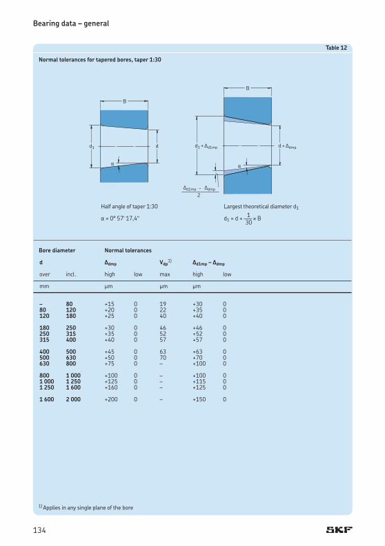
Half angle of taper 1:30
a = 0° 57© 17,4@
1) Applies in any single plane of the bore
Table12
Normaltolerancesfortaperedbores,taper1:30
Borediameter Normaltolerances
d Ddmp Vdp1) Dd1mp–Ddmp
over incl. high low max high low
mm mm mm mm
Largest theoretical diameter d1 1d1 = d + ––– ¥ B 30
134

0,05 – – 0,1 0,2 0,10,08 – – 0,16 0,3 0,160,1 – – 0,2 0,4 0,2 0,15 – – 0,3 0,6 0,30,2 – – 0,5 0,8 0,50,3 – 40 0,6 1 0,8 40 – 0,8 1 0,8 0,6 – 40 1 2 1,5 40 – 1,3 2 1,51 – 50 1,5 3 2,2 50 – 1,9 3 2,21,1 – 120 2 3,5 2,7 120 – 2,5 4 2,7 1,5 – 120 2,3 4 3,5 120 – 3 5 3,52 – 80 3 4,5 4 80 220 3,5 5 4 220 – 3,8 6 42,1 – 280 4 6,5 4,5 280 – 4,5 7 4,5 2,5 – 100 3,8 6 – 100 280 4,5 6 – 280 – 5 7 –3 – 280 5 8 5,5 280 – 5,5 8 5,5 4 – – 6,5 9 6,55 – – 8 10 86 – – 10 13 10 7,5 – – 12,5 17 12,59,5 – – 15 19 1512 – – 18 24 18
Table13
Chamferdimensionlimitsformetricradialandthrustbearings,excepttaperrollerbearings
Minimum Nominal Maximumchamfersingle bearing dimensionschamfer bore Radial Thrustdimension diameter bearings bearings
rsmin d r1,3 r2,4 r1,2,3,4 over incl. max max max
mm mm mm
0,3 – 40 0,7 1,4 40 – 0,9 1,6 0,6 – 40 1,1 1,7 40 – 1,3 2 1 – 50 1,6 2,5 50 – 1,9 3 1,5 – 120 2,3 3 120 250 2,8 3,5 250 – 3,5 4 2 – 120 2,8 4 120 250 3,5 4,5 250 – 4 5 2,5 – 120 3,5 5 120 250 4 5,5 250 – 4,5 6 3 – 120 4 5,5 120 250 4,5 6,5 250 400 5 7 400 – 5,5 7,5 4 – 120 5 7 120 250 5,5 7,5 250 400 6 8 400 – 6,5 8,5 5 – 180 6,5 8 180 – 7,5 9 6 – 180 7,5 10 180 – 9 11
Table14
Chamferdimensionlimitsformetricradialtaperrollerbearings
Minimum Nominalbearing Maximumchamfersingle bore/outside dimensionschamfer diameter dimension
rsmin d,D r1,3 r2,4 over incl. max max
mm mm mm
135

Bearing data – general
0,6 1,4 101,6 r1 min + 0,5 r2 min + 1,3 168,3 r3 min + 0,6 r4 min + 1,2 101,6 254 r1 min + 0,6 r2 min + 1,8 168,3 266,7 r3 min + 0,8 r4 min + 1,4 254 r1 min + 0,9 r2 min + 2 266,7 355,6 r3 min + 1,7 r4 min + 1,7 355,6 r3 min + 0,9 r4 min + 2 1,4 2,5 101,6 r1 min + 0,5 r2 min + 1,3 168,3 r3 min + 0,6 r4 min + 1,2 101,6 254 r1 min + 0,6 r2 min + 1,8 168,3 266,7 r3 min + 0,8 r4 min + 1,4 254 r1 min + 2 r2 min + 3 266,7 355,6 r3 min + 1,7 r4 min + 1,7 355,6 r3 min + 2 r4 min + 3 2,5 4,0 101,6 r1 min + 0,5 r2 min + 1,3 168,3 r3 min + 0,6 r4 min + 1,2 101,6 254 r1 min + 0,6 r2 min + 1,8 168,3 266,7 r3 min + 0,8 r4 min + 1,4 254 400 r1 min + 2 r2 min + 4 266,7 355,6 r3 min + 1,7 r4 min + 1,7 400 r1 min + 2,5 r2 min + 4,5 355,6 400 r3 min + 2 r4 min + 4 400 r3 min + 2,5 r4 min + 4,5 4,0 5,0 101,6 r1 min + 0,5 r2 min + 1,3 168,3 r3 min + 0,6 r4 min + 1,2 101,6 254 r1 min + 0,6 r2 min + 1,8 168,3 266,7 r3 min + 0,8 r4 min + 1,4 254 r1 min + 2,5 r2 min + 4 266,7 355,6 r3 min + 1,7 r4 min + 1,7 355,6 r3 min + 2,5 r4 min + 4 5,0 6,0 101,6 r1 min + 0,5 r2 min + 1,3 168,3 r3 min + 0,6 r4 min + 1,2 101,6 254 r1 min + 0,6 r2 min + 1,8 168,3 266,7 r3 min + 0,8 r4 min + 1,4 254 r1 min + 3 r2 min + 5 266,7 355,6 r3 min + 1,7 r4 min + 1,7 355,6 r3 min + 3 r4 min + 5 6,0 7,5 101,6 r1 min + 0,5 r2 min + 1,3 168,3 r3 min + 0,6 r4 min + 1,2 101,6 254 r1 min + 0,6 r2 min + 1,8 168,3 266,7 r3 min + 0,8 r4 min + 1,4 254 r1 min + 4,5 r2 min + 6,5 266,7 355,6 r3 min + 1,7 r4 min + 1,7 355,6 r3 min + 4,5 r4 min + 6,5 7,5 9,5 101,6 r1 min + 0,5 r2 min + 1,3 168,3 r3 min + 0,6 r4 min + 1,2 101,6 254 r1 min + 0,6 r2 min + 1,8 168,3 266,7 r3 min + 0,8 r4 min + 1,4 254 r1 min + 6,5 r2 min + 9,5 266,7 355,6 r3 min + 1,7 r4 min + 1,7 355,6 r3 min + 6,5 r4 min + 9,5 9,5 12 101,6 r1 min + 0,5 r2 min + 1,3 168,3 r3 min + 0,6 r4 min + 1,2 101,6 254 r1 min + 0,6 r2 min + 1,8 168,3 266,7 r3 min + 0,8 r4 min + 1,4 254 r1 min + 8 r2 min + 11 266,7 355,6 r3 min + 1,7 r4 min + 1,7 355,6 r3 min + 8 r4 min + 11
Table15
Chamferdimensionlimitsforinchtaperrollerbearings
Minimum Innerring Outerringsingle Nominal Maximumchamfer Nominal Maximumchamferchamfer bearingbore dimensions bearingoutside dimensionsdimension diameter diameter
rsmin d r1 r2 D r3 r4over incl. over incl. max max over incl. max max
mm mm mm mm mm
136

Bearing internal clearanceBearing internal clearance (†fig.5) is defined as the total distance through which one bearing ring can be moved relative to the other in the radial direction (radial internal clearance) or in the axial direction (axial internal clearance).
It is necessary to distinguish between the internal clearance of a bearing, before mounting and the internal clearance in a mounted bear-ing, which has reached its operating tempera-ture (operational clearance). The initial internal clearance (before mounting) is greater than the operational clearance because different degrees of interference in the fits and differences in thermal expansion of the bearing rings and the associated components cause the rings to be expanded or compressed.
The radial internal clearance of a bearing is of considerable importance if satisfactory operation is to be obtained. As a general rule, ball bearings should always have an operational clearance that is virtually zero, or there may be a slight preload. Cylindrical, spherical and CARB toroidal roller bearings, on the other hand, should always have some residual clearance – however small – in operation. The same is true of taper roller bearings, except in bear-ing arrangements where stiffness is desired, e.g. pinion bearing arrangements, where the bearings are mounted with a certain amount of preload (†section “Bearing preload”, starting on page206).
The bearing internal clearance referred to as Normal has been selected so that a suitable
operational clearance will be obtained when bearings are mounted with the fits usually rec-ommended and operating conditions are nor-mal. Where operating and mounting conditions differ from the normal, e.g. where interference fits are used for both bearing rings, unusual temperatures prevail etc., bearings with greater or smaller internal clearance than Normal are required. In such cases, SKF recommends checking residual clearance in the bearing after it has been mounted.
Bearings having an internal clearance other than Normal are identified by the suffixes C1 to C5 (†table16).
Tables providing the clearance values for the various bearing types can be found in the text preceding the relevant product section. For paired single row angular contact ball bearings and taper roller bearings, double row angular contact ball bearings and four-point contact ball bearings, values for the axial internal clearance are provided instead of radial clearance, as the axial clearance is of greater importance in appli-cation design for these bearing types.
Table16
Supplementarydesignationforinternalclearance
Suffix Internalclearance
C1 Less than C2
C2 Less than Normal
CN Normal, only used in combination with letters indicating reduced or displaced clearance range.
C3 Greater than Normal
C4 Greater than C3
C5 Greater than C4
Fig.5
Axial internal clearance
Radial internal clearance
137

Materials for rolling bearingsThe materials from which the bearing compon-ents are made determine to a large extent the performance and reliability of rolling bearings. For the bearing rings and rolling elements typ-ical considerations include hardness for load carrying capacity, fatigue resistance under roll-ing contact conditions, under clean or contamin-ated lubrication conditions, and the dimensional stability of the bearing components. For the cage, considerations include friction, strain, inertia forces, and in some cases, the chemical action of certain lubricants, solvents, coolants and refrigerants. The relative importance of these considerations can be affected by other operational parameters such as corrosion, elevated temperatures, shock loads or combin-ations of these and other conditions.
Because SKF has the competence and facil-ities to provide a variety of materials, processes and coatings, SKF application engineers can assist in selecting those bearings that will provide superior performance for particular applications.
Contact seals integrated in rolling bearings can also have a considerable impact on the performance and reliability of the bearings. The materials they are made of have to offer excel-lent oxidation, thermal or chemical resistance.
In order to meet the needs of various applica-tions, SKF uses different materials for bearing rings, rolling elements, cages and seals. Fur-thermore, in applications where sufficient lubri-cation cannot be achieved or where an electric current passing through the bearings has to be prevented, SKF bearings can be supplied with special coatings.
Materials for bearing rings and rolling elements
Bearing steels for through-hardeningThe most common steel for through-hardening is a carbon chromium steel, containing approxi-mately 1 % carbon and 1,5 % chromium, accord- ing to ISO 683-17:1999. Today, carbon- chromium steel is one of the oldest and most intensively investigated steels; due to the continuously increasing demands for extended bearing service life. The composition of this roll-
ing bearing steel provides an optimum balance between manufacturing and application per-formance. This steel is normally given a mar-tensitic or bainitic heat treatment during which it is hardened to the range of 58 to 65 HRC.
Within the last few years process develop-ments have enabled more stringent cleanliness specifications to be realized, which has had a significant impact on the consistency and quality of SKF’s bearing steel. The reduction of oxygen and harmful non-metallic inclusions has led to significantly improved properties of rolling bearing steels – the steels from which the SKF Explorer class bearings are made.
Bearing steels for induction-hardeningSurface induction-hardening offers the possibil-ity to selectively harden a component’s raceway, while leaving the remainder of the component unaffected by the hardening process. The steel grade and the manufacturing processes used prior to surface induction-hardening dictate the properties in the unaffected area, which means that a combination of properties can be achieved in one component.
An example of this is a flanged wheel hub bearing unit (HBU) where the properties of the unhardened flange are designed to resist struc-tural fatigue, while the raceway is designed to resist rolling contact fatigue.
Bearing steels for case-hardeningChromium-nickel and manganese-chromium alloyed steels according to ISO 683-17:1999 with a carbon content of approximately 0,15 % are those steels for case-hardening most com-monly used for SKF rolling bearings.
In applications where there are high tensile interference fits and heavy shock loads, bear-ings with case-hardened rings and/or rolling elements are recommended.
Stainless bearing steelsThe most common stainless steels used for SKF bearing rings and rolling elements are the high chromium content steels X65Cr14 according to ISO 683-17:1999 and X105CrMo17 according to EN 10088-1:1995.
It should be noted that for some applications, corrosion resistant coatings might be an excel-lent alternative to stainless steel. For additional information about alternative coatings, please consult the SKF application engineering service.
Bearing data – general
138

High-temperature bearing steelsDepending on the bearing type, standard bear-ings made from steels for through-hardening and surface-hardening have a recommended maximum operating temperature, which dif-fers between 120 and 200 °C. The maximum operating temperature is directly related to the heat treatment process used in manufacturing components.
For operating temperatures up to 250 °C; a special heat treatment (stabilization) can be applied. In this case a reduction of the load carry-ing capacity of the bearing has to be taken into account.
For bearings operated at elevated tempera-tures, higher than 250 °C, for extended periods, highly alloyed steels like the 80MoCrV42-16 manufactured to ISO 683-17:1999 should be used, because they retain their hardness and bearing performance characteristics even under extreme temperature conditions.
For additional information about high tem-perature bearing steels, please contact the SKF application engineering service.
CeramicsThe common ceramic used for SKF bearing rings and rolling elements is a bearing grade silicon nitride material. It consists of fine elongated grains of beta-silicon nitride in a glassy phase matrix. It provides a combination of favourable properties for rolling bearings, such as high hard-ness, low density, low thermal expansion, high electric resistivity, low dielectric constant and no response to magnetic fields (†table17).
Table17
Comparisonofthematerialpropertiesofbearingsteelandsiliconnitride
Material Bearing Bearinggradeproperties steel siliconnitride
MechanicalpropertiesDensity (g/cm3) 7,9 3,2Hardness 700 HV10 1 600 HV10Modulus of elasticity (kN/mm2) 210 310Thermal expansion (10–6/K) 12 3
Electricalproperties (at 1 MHz)Electrical resistivity (Wm) 0,4 ¥ 10–6 1012
(Conductor) (Insulator)Dielectric strength (kV/mm) – 15Relative dielectric constant – 8
139

Cage materials
Sheet steel cagesThe majority of pressed sheet steel cages are made from continuously hot-rolled low carbon sheet steel according to EN 10111:1998. These lightweight cages have relatively high strength and can be surface treated to further reduce friction and wear.
Pressed cages normally used in stainless steel bearings are made from stainless steel X5CrNi18-10 according to EN 10088-1:1995.
Machined steel cages Machined steel cages are normally made of non-alloyed structural steel of type S355GT (St 52) according to EN 10 025:1990 + A:1993. To improve sliding and wear-resistance prop-erties some machined steel cages are surface treated.
Machined steel cages are used for large-size bearings or in applications where there is a dan-ger that season cracking, caused by a chemical reaction, may occur if a brass cage were used. Steel cages can be used at operating tempera-tures up to 300 °C. They are not affected by the mineral or synthetic oil-based lubricants nor-mally used for rolling bearings, or by the organic solvents used to clean bearings.
Sheet brass cagesPressed sheet brass cages are used for some small and medium-sized bearings. The brass used for these cages conforms to EN 1652:1997. In applications such as compressors for refriger-ation using ammonia, season cracking in sheet brass might occur, therefore machined brass or steel cages should be used instead.
Machined brass cagesMost brass cages are machined from a CW612N cast or wrought brass according to EN 1652:1997. They are unaffected by most common bearing lubricants, including synthetic oils and greases, and can be cleaned using nor-mal organic solvents. Brass cages should not be used at temperatures in excess of 250 °C.
Polymer cages
Polyamide 6,6For the majority of injection moulded cages polyamide 6,6 is used. This material, with glass fibre reinforcement or without, is character-ized by a favourable combination of strength and elasticity. The mechanical properties like strength and elasticity of polymeric materials are temperature dependent and subject to per-manent changes under operating conditions, called ageing. The most important factors that play a role in this ageing behaviour are tem-perature, time and the medium (lubricant) to which the polymer is exposed. The relationship between these factors for glass fibre reinforced polyamide 6,6 is illustrated in diagram1. It appears that the cage life decreases with increas-ing temperature and the aggressiveness of the lubricant.
Therefore, whether polyamide cages are suitable for a specific application depends on the operating conditions and life requirements. In table18 the classification of lubricants into “aggressive” and “mild” is reflected by the “per-missible operating temperature” for the use of cages made from glass fibre reinforced poly-amide 6,6 in various lubricants. The permissible operating temperature in this table is defined as the temperature, which gives a cage ageing life of at least 10 000 operating hours.
Some media are even more “aggressive” than those listed in table18. A typical example is ammonia applied as refrigerant in compressors. In those cases, cages made from glass fibre reinforced polyamide 6,6 should not be used at operating temperatures above +70 °C.
Towards the low operating temperature side, also a limit can be set since polyamide loses its elasticity, which can result in cage failures. Cages made from glass fibre reinforced poly-amide 6,6 should for this reason not be applied at a continuous operating temperature below –40 °C.
Where a high degree of toughness is a dominant factor, such as in railway axleboxes, a super-tough modification of polyamide 6,6 is applied. Please consult the SKF application engineering service for cage availability for spe-cific bearing executions.
Bearing data – general
140

Polyamide 4,6Glass fibre reinforced polyamide 4,6 is used for some small and medium size CARB toroidal roller bearings as standard. These cages have a 15 °C higher permissible operating temperature than those made from glass fibre reinforced polyamide 6,6.
Polyetheretherketone (PEEK)The use of the glass fibre reinforced PEEK for cages has become common within SKF for demanding conditions regarding high speeds, chemical attack or high temperatures. The exceptional properties of PEEK are superior combination of strength and flexibility, high operating temperature range, high chemical and wear resistance and good processability. Due to these outstanding features, PEEK cages are available as standard for some ball and cylindric-al roller bearings, like hybrid and/or high-preci-sion bearings. The material does not show signs of ageing by temperature and oil additives up to +200 °C. However, the maximum temperature for high-speed use is limited to +150 °C as this is the softening temperature of the polymer.
Table18
Permissibleoperatingtemperaturesforcagesofglassfibrereinforcedpolyamide6,6withvariousbearinglubricants
Lubricant Permissible operating tempera-ture1)
MineraloilsOils without EP additives, e.g. machine or hydraulic oils 120 °C Oils with EP additives, e.g. industrial and automotive gearbox oils 110 °C Oils with EP additives, e.g. automotive rear axle and differential gear oils (automotive), hypoid gear oils 100 °C
SyntheticoilsPolyglycols, poly-alpha-olefins 120 °CDiesters, silicones 110 °CPhosphate esters 80 °C
GreasesLithium greases 120 °CPolyurea, bentonite, calcium complex greases 120 °C
For sodium and calcium greases and other greases with a maximum operating temperature below 120 °C, the maximum temperature for the polyamide cage is the same as the maximum operating temperature for the grease.
1) Measured on the outside surface of the outer ring
Diagram1
Cageageinglifeforglassfibrereinforcedpolyamide6,6
Bearing temperature, °C
mild lubricants
aggressive lubricantsCage ageing life, hours
141

Phenolic resin Lightweight, fabric reinforced phenolic resin cages can withstand heavy centrifugal as well as acceleration forces, but are not able to accom-modate high operating temperatures. In most cases, these cages are used as standard in high-precision angular contact ball bearings.
Other materialsIn addition to the materials described above, SKF bearings for special applications may be fit-ted with cages made of other engineering poly-mer materials, light alloys or special cast iron. For information on cages made from alternative materials please consult the SKF application engineering service.
Seal materialsSeals integrated in SKF bearings are typically made from elastomer materials. The type of material can depend on the series and size of the bearing as well as the application require-ments. SKF seals are generally produced from the materials listed below.
Acrylonitrile-butadiene rubber Acrylonitrile-butadiene rubber (NBR) is the “universal” seal material. This copolymer, pro-duced from acrylonitrile and butadiene, shows good resistance to the following media
• most mineral oils and greases with a mineral oil base
• normal fuels: petrol, diesel and light heating oils
• animal and vegetable oils and fats • hot water.
It also tolerates short-term dry running of the sealing lip. The permissible operating tempera-ture range is –40 to +100 °C; for brief periods temperatures of up to +120 °C can be tolerated. At higher temperatures the material hardens.
Hydrogenated acrylonitrile-butadiene rubberHydrogenated acrylonitrile-butadiene rubber (HNBR) has appreciably better wear character-istics than nitrile rubber so that seals made of this material have a longer service life. Hydro-genated acrylonitrile-butadiene rubber is also
more resistant to heat, ageing and hardening in hot oil or ozone.
Mixtures of oil in air may have a negative impact on seal life. The upper operating tem-perature limit is +150 °C, which is appreciably higher than that of normal nitrile rubber.
Fluoro rubber Fluoro rubbers (FKM) are characterized by their high thermal and chemical resistance. Their resistance to ageing and ozone is very good and their gas permeability is very slight. They have exceptionally good wear-characteristics even under harsh environmental conditions and can withstand operating temperatures up to +200 °C. Seals made from this material can tol-erate dry running of the lip for short periods.
Fluoro rubbers are also resistant to oils and hydraulic fluids, fuels and lubricants, mineral acids and aliphatic as well as aromatic hydro-carbons, which would cause seals made from other materials to fail. In the presence of esters, ethers, ketones, certain amines and hot anhy-drous hydrofluorides fluoro rubbers should not be used.
At temperatures above 300 °C, fluoro rubber gives off dangerous fumes. As handling seals made of fluoro rubber constitutes a potential safety risk, the safety precautions mentioned hereafter must always be considered.
PolyurethanePolyurethane (AU) is a wear-resistant organic material, which has good elastic properties. It withstands operating temperatures in the range of –20 up to +80 °C. It has good resistance to mineral oil based greases, mineral oils with no or low quantity of EP additives, water and water-oil mixtures for example. It is not resist-ant to acids, alkalics or polar solvents.
Bearing data – general
142

WARNING!SafetyprecautionsforfluororubberFluoro rubber is very stable and harm-less in normal operating conditions up to +200 °C. However, if exposed to extreme temperatures above 300 °C, e.g. fire or the flame of a cutting torch, fluoro rubber seals give off hazardous fumes. These fumes can be harmful if inhaled, as well as to the eyes. In addition, once the seals have been heated to such temperatures, they are dangerous to handle even after they have cooled and should not be in contact with the skin. If it is necessary to handle bear-ings with seals that have been subjected to high temperatures, such as when dis-mounting the bearing, the following safety precautions should be observed:
• Always wear protective goggles, gloves and appropriate breathing apparatus.
• Place the remains of the seals in an air-tight plastic container marked with a symbol for “material will etch”.
• Follow the safety precautions in the appropriate material safety data sheet (MSDS).
If there is unintentional contact with the seals, wash hands with soap and plenty of water and flush eyes with plenty of water and consult a doctor immediately. If the fumes have been inhaled, consult a doctor immediately.
The user is responsible for the cor-rect use of the product during its service life and its proper disposal. SKF takes no responsibility for the improper handling of fluoro rubber seals or for any injury result-ing from their use.
CoatingsCoating is a well-established method to upgrade materials and to provide bearings with addition- al features for specific application conditions. Two different coating methods developed by SKF are available and already successfully proven in many applications.
The surface coating, trademarked NoWear, applies a low friction ceramic coating on the bearing inner surfaces to withstand long periods of operation under marginal lubrication for example. More details can be found in the sec-tion “NoWear bearings”, starting on page943.
The INSOCOAT® coating, which can be applied to the external surfaces of the outer ring or inner ring of a bearing, offers resistance to the damage that can be caused by the passage of electric current through the bearing. More details can be found in the section “INSOCOAT bearings”, starting on page911.
Other coatings like zinc chromate for example, can offer an alternative to stainless steel in a corrosive environment, especially for ready-to-mount bearing units.
143

CagesCages have an appreciable influence on the suit-ability of rolling bearings. Their main purposes are
• keeping the rolling elements at an appropri-ate distance from each other and to prevent direct contact between neighbouring rolling elements, in order to keep friction and thus heat generation at a minimum
• keeping the rolling elements evenly distrib-uted around the complete circumference to provide even load distribution and quiet and uniform running
• guiding the rolling elements in the unloaded zone, to improve the rolling conditions in the bearing and to prevent damaging sliding movements
• retaining the rolling elements, where bear-ings are of a separable design and one bearing ring is removed during mounting or dismounting.
Cages are mechanically stressed by frictional, strain and inertia forces and they may also be subjected to the chemical action of certain lubri-cants, lubricant additives or products of their ageing, organic solvents or coolants. Therefore the design and material are of paramount importance for the performance of the cage as well as for the operational reliability of the bear-ing itself. This is the reason why SKF has devel-oped various cage types and designs of different materials for the different bearing types.
In the introductory text to each product sec-tion information is provided about the standard cages fitted to the bearings and also possible alternatives. If a bearing with a non-standard cage is required, it is always advisable to check availability before ordering.
In general, the cages for SKF rolling bearings can be classified as pressed, solid or pin-type cages
Pressed cagesPressed cages for SKF bearings (†fig.6) gen-erally are made of sheet steel and with some exceptions of sheet brass. Depending on the bearing type pressed cages are designed as
• ribbon-type brass or steel cage (a)• riveted steel cage (b)• snap-type brass or steel cage (c)• extremely strong window-type steel cage (d).
Pressed cages offer the advantage of lower weight as well as the advantage of more space inside the bearing, which facilitates entry of the lubricant into the bearing.
Bearing data – general
Fig.6
a b c d
144

Solid cagesSolid cages for SKF bearings (†fig.7) are made from brass, steel, light alloy, polymer or fabric reinforced phenolic resin. Depending on the bearing design they are designed as
• two-piece machined riveted cage (a)• two-piece machined cage with integral
rivets (b)• one-piece machined window-type cage (c)• double pronged machined cage (d)• injection moulded polymer window-type
cage (e)• injection moulded polymer snap-type cage (f)• one-piece machined cage of fabric reinforced
phenolic resin.
Machined metal cages generally permit higher speeds and are necessary when movements additional to pure rotation are superimposed, particularly when conditions of high acceler-ation prevail. Suitable steps must be taken (e.g. oil lubrication) to provide sufficient supply of lubricant to the guiding surfaces of the cage and to the inside of the bearing. Machined cages are centred (†fig.8) either on the
• rolling elements (a)• inner ring shoulder(s) (b)• outer ring shoulder(s) (c)
and are thus radially guided.
Fig.8
a
b
c
Fig.7
a b c c d e f
145

Solid polymer cages are characterized by a favourable combination of strength and elasti-city. The good sliding properties of the polymer on lubricated steel surfaces and the smoothness of the cage surfaces in contact with the rolling elements produce just little friction so that heat generation and wear in the bearing are at a minimum. The low density of the material means that the inertia of the cage is small. The excellent running properties of polymer cages under lubricant starvation conditions permit continued operation of the bearing for some time without risk of seizure and secondary damage.
Pin-type cagesSteel pin-type cages need pierced rollers (†fig.9) and are only used together with large-sized roller bearings. These cages have relative low weight and enable a large number of rollers being incorporated.
MaterialsDetailed information about materials used for cages can be found in the section “Materials for rolling bearings”, starting on page138.
Fig.9
Bearing data – general
146

DesignationsDesignations of rolling bearings consist of combinations of figures and/or letters, the significance of which is not immediately appar-ent. Therefore, the SKF designation system for rolling bearings will be described and the sig-nificance of the more common supplementary designations explained. To avoid confusion, the designations used for specific rolling bearing types, such as needle roller bearings, Y-bear-ings or high-precision bearings are not covered. More information about these can be found in the relevant catalogues. Also very specific bear-ing types, such as fixed-section bearings, slew-ing bearings or linear bearings are not covered either. These designations differ sometimes considerably from the system described here.
Bearing designations are divided into two main groups: designations for standard bear-ings and designations for special bearings. Standard bearings are bearings that normally have standardized dimensions, whereas special bearings have special dimensions dictated by customer demands. These customized bearings are also referred to as “drawing number” bear-ings and they will not be covered in detail in this section.
The complete designation may consist of a basic designation with or without one or more supplementary designations (†diagram2). The complete bearing designation, i.e. the basic designation with supplementary designations is always marked on the bearing package, where-as the designation marked on the bearing may sometimes be incomplete, e.g. for manufactur-ing reasons.
Basic designations identify the
• type• basic design• standard boundary dimensions
of a bearing. Supplementary designations identify
• bearing components and/or• variants having a design and/or feature(s) that
differ in some respect from the basic design.
Supplementary designations may precede the basic designation (prefixes) or follow it (suffixes). Where several supplementary designations
are used to identify a given bearing, they are always written in a given order (†diagram4, page150).
The list of supplementary designations pre-sented in the following is not exhaustive, but includes those most commonly used.
Diagram2
Bearingdesignationsystem
Examples
Prefix
Spaceornon-separated
Basicdesignation
Space,obliquestrokeorhyphen
Suffix
R NU 2212 ECMLW 6008 / C3
23022 – 2CS
147

Basic designationsAll SKF standard bearings have a characteristic basic designation, which generally consists of 3, 4 or 5 figures, or a combination of letters and figures. The design of the system used for almost all standard ball and roller bearing types is shown schematically in diagram3. The figures and combinations of letters and figures have the following meaning:
• The first figure or the first letter or combin-ation of letters identifies the bearing type; the actual bearing type can be seen from the presentation (†diagram3).
• The following two figures identify the ISO Dimension Series; the first figure indicates the Width or Height Series (dimensions B, T or H) and the second the Diameter Series (dimension D).
• The last two figures of the basic designation give the size code of the bearing; when multi-plied by 5, the bore diameter in millimetres is obtained.
But there is no rule without some exceptions. The most important ones in the bearing desig-nation system are listed below.
1. In a few cases the figure for the bearing type and/or the first figure of the Dimension Series identification is omitted. These figures are given in brackets in diagram3.
2. For bearings having a bore diameter smaller than 10 mm or equal to or greater than 500 mm, the bore diameter is generally given in millimetres and is not coded. The size iden-tification is separated from the rest of the bearing designation by an oblique stroke, e.g. 618/8 (d = 8 mm) or 511/530 (d = 530 mm).
This is also true of standard bearings according to ISO 15:1998 that have bore diameters of 22, 28 or 32 mm, e.g. 62/22 (d = 22 mm).
3. Bearings with bore diameters of 10, 12, 15 and 17 mm have the following size code identifications: 00 = 10 mm 01 = 12 mm 02 = 15 mm 03 = 17 mm
4. For some smaller bearings having a bore diam-eter below 10 mm, such as deep groove, self-aligning and angular contact ball bearings, the bore diameter is also given in millimetres (uncoded) but is not separated from the series designation by an oblique stroke, e.g. 629 or 129 (d = 9 mm).
5. Bore diameters that deviate from the stand-ard bore diameter of a bearing have always been given uncoded, in millimetres with up to three decimal places. This bore diameter identification is part of the basic designation and is separated from the basic designation by an oblique stroke, e.g. 6202/15.875 (d = 15,875 mm = 5/8 in).
Series designationsEach standard bearing belongs to a given bear-ing series, which is identified by the basic des-ignation without the size identification. Series designations often include a suffix A, B, C, D or E or a combination of these letters e.g. CA. These are used to identify differences in internal design, e.g. contact angle.
The most common series designations are shown in diagram3 above the bearing sketches. The figures in brackets are not included in the series designation.
Bearing data – general
148

Diagram3
DesignationsystemforSKFstandardmetricballandrollerbearings
Bearingseries
Bearingseries
Radialbearing Thrustbearings Width (B, T) Height (H)
DiameterSeries
Dimen- Size sion Series
Bearingtype
Code Bearingtype
0 Double row angular contact ball bearings
1 Self-aligning ball bearings2 Spherical roller bearings,
spherical roller thrust bearings3 Taper roller bearings4 Double row deep groove ball
bearings5 Thrust ball bearings6 Single row deep groove ball
bearings
Code Bearingtype
7 Single row angular contact ball bearings
8 Cylindrical roller thrust bearingsC CARB toroidal roller bearingsN Cylindrical roller bearings.
A second and sometimes a third letter are used to identify the number of the rows or the configuration of the flanges, e.g. NJ, NU, NUP, NN, NNU, NNCF etc.
Code Bearingtype
QJ Four-point contact ball bearings
T Taper roller bearings according to ISO 355-1977
149

Bearing data – general
Diagram4
Designationsystemforsuffixes
Designationexample
6205-RS1NRTN9/P63LT20CVB123
23064 CCK/HA3C084S2W33
Basic designation
Space
Suffixes
Group 1: Internal design
Group 2: External design (seals, snap ring groove etc.)
Group 3: Cage design
Oblique stroke
Group 4: Variants
Group 4.1: Materials, heat treatment
Group 4.2: Accuracy, clearance, quiet running
Group 4.3: Bearing sets, paired bearings
Group 4.4: Stabilization
Group 4.5: Lubrication
Group 4.6: Other variants
6205 -RS1NR TN9 / P63 LT20C VB123
23064 CC K / HA3 C084 S2 W33
4.1 4.2 4.3 4.4 4.5 4.61 2 3 / 4
Group Group Group Group
150

Supplementary designations
PrefixesPrefixes are used to identify components of a bearing and are usually then followed by the designation of the complete bearing, or to avoid confusion with other bearing designations. For example they are used in front of designations for taper roller bearings according to a system described in ANSI/ ABMA Standard 19 for (pre-dominantly) inch bearings.
GS Housing washer of a cylindrical roller thrust bearing
K Cylindrical roller and cage thrust assem-bly
K- Inner ring with roller and cage assembly (cone) or outer ring (cup) of inch taper roller bearing belonging to an ABMA standard series
L Separate inner or outer ring of a separ-able bearing
R Inner or outer ring with roller (and cage) assembly of a separable bearing
W Stainless steel deep groove ball bearing WS Shaft washer of a cylindrical roller thrust
bearingZE Bearing with SensorMount® feature
SuffixesSuffixes are used to identify designs or variants which differ in some way from the original de-sign, or which differ from the current standard design. The suffixes are divided into groups and when more than one special feature is to be identified; suffixes are provided in the order shown in the scheme in diagram4.
The most commonly used suffixes are listed below. Note that not all variants are available.
A Deviating or modified internal design with the same boundary dimensions. As a rule the significance of the letter is bound to the particular bearing or bear-ing series. Examples: 4210 A: Double row deep groove ball bearing without filling slots 3220 A: Double row angular contact ball bearing without filling slots
AC Single row angular contact ball bearing with a 25° contact angle
ADA Modified snap ring grooves in the outer ring; a two-piece inner ring held to-gether by a retaining ring
B Deviating or modified internal design with the same boundary dimensions. As a rule the significance of the letter is bound to the particular bearing series. Examples: 7224 B: Single row angular contact ball bearing with a 40° contact angle 32210 B: Steep contact angle taper roller bearing
Bxx(x) B combined with a two or three-figure number identifies variants of the stand-ard design that cannot be identified by generally applicable suffixes. Example: B20: Reduced width tolerance
C Deviating or modified internal design with the same boundary dimensions. As a rule the significance of the letter is bound to the particular bearing series. Example: 21306 C: Spherical roller bearing with a flangeless inner ring, symmetrical rollers, loose guide ring and a pressed window-type steel cage
151

CA 1. Spherical roller bearing of C design, but with retaining flanges on the inner ring and a machined cage
2. Single row angular contact ball bear-ing for universal matching. Two bear-ings arranged back-to-back or face-to-face will have an axial internal clearance smaller than Normal (CB) before mounting
CAC Spherical roller bearing of the CA design but with enhanced roller guidance
CB 1. Single row angular contact ball bearing for universal matching. Two bearings arranged back-to-back or face-to-face will have a Normal axial internal clearance before mounting
2. Controlled axial clearance of a double row angular contact ball bearing
CC 1. Spherical roller bearing of C design but with enhanced roller guidance
2. Single row angular contact ball bearing for universal matching. Two bearings arranged back-to-back or face-to-face will have an axial intern-al clearance larger than Normal (CB) before mounting
CLN Taper roller bearing with tolerances corresponding to ISO tolerance class 6X
CL0 Inch taper roller bearing with tolerances to class 0 according to ANSI/ABMA Standard 19.2:1994
CL00 Inch taper roller bearing with tolerances to class 00 according to ANSI/ABMA Standard 19.2:1994
CL3 Inch taper roller bearing with tolerances to class 3 according to ANSI/ABMA Standard 19.2:1994
CL7C Taper roller bearing with special fric-tional behaviour and heightened running accuracy
CN Normal internal clearance, normally only used together with an additional letter that identifies a reduced or dis-placed clearance range. Examples: CNH Upper half of the Normal clear-
ance rangeCNL Lower half of the Normal clear-
ance rangeCNM Two middle quarters of the Nor-
mal clearance rangeCNP Upper half of the Normal and
lower half of C3 clearance The above letters H, L, M and P are also
used together with the clearance classes C2, C3, C4 and C5
CV Full complement cylindrical roller bear-ing with modified internal design
CS Sheet steel reinforced contact seal of acrylonitrile-butadiene rubber (NBR) on one side of the bearing
2CS CS contact seal on both sides of the bearing
CS2 Sheet steel reinforced contact seal of fluoro rubber (FKM) on one side of the bearing
2CS2 CS2 contact seal on both sides of the bearing
CS5 Sheet steel reinforced contact seal of hydrogenated acrylonitrile-butadiene rubber (HNBR) on one side of the bear-ing
2CS5 CS5 contact seal on both sides of the bearing
C1 Bearing internal clearance smaller than C2
C2 Bearing internal clearance smaller than Normal (CN)
C3 Bearing internal clearance greater than Normal (CN)
C4 Bearing internal clearance greater than C3
C5 Bearing internal clearance greater than C4
C02 Extra reduced tolerance for running accuracy of inner ring of assembled bearing
C04 Extra reduced tolerance for running accuracy of outer ring of assembled bearing
C08 C02 + C04C083 C02 + C04 + C3C10 Reduced tolerance for the bore and
outside diameters
Bearing data – general
152
D Deviating or modified internal design with the same boundary dimensions; as a rule the significance of the letter is bound to the particular bearing series. Example: 3310 D: Double row angular contact ball bearing with a two-piece inner ring
DA Modified snap ring grooves in the outer ring; two-piece inner ring held together by a retaining ring
DB Two single row deep groove ball bear-ings (1), single row angular contact ball bearings (2) or single row taper roller bearings matched for mounting in a back-to-back arrangement. The letter(s) following the DB indicate the magnitude of the axial internal clearance or preload in the bearing pair before mounting.A Light preload (2)B Moderate preload (2)C Heavy preload (2)CA Axial internal clearance smaller than
Normal (CB) (1, 2)CB Normal axial internal clearance
(1, 2)CC Axial internal clearance larger than
Normal (CB) (1, 2)C Special axial internal clearance in mm
GA Light preload (1)GB Moderate preload (1)G Special preload in daNFor paired taper roller bearings the design and arrangement of the inter-mediate rings between the inner and outer rings are identified by a two-figure number which is placed between DB and the above mentioned letters.
DF Two single row deep groove ball bear-ings, single row angular contact ball bearings or single row taper roller bearings matched for mounting in a face-to-face arrangement. The letter(s) following the DF are explained under DB
DT Two single row deep groove ball bear-ings, single row angular contact ball bearings or single row taper roller bear-ings matched for mounting in a tandem arrangement; for paired taper roller bearings the design and arrangement of the intermediate rings between the inner and/or outer rings are identified by a two-figure number which follows immediately after DT
E Deviating or modified internal design with the same boundary dimensions; as a rule the significance of the letter is bound to the particular bearing series; usually indicates reinforced rolling elem-ent complement. Example: 7212 BE: Single row angular contact ball bearing with a 40° contact angle and optimized internal design
EC Single row cylindrical roller bearing with an optimized internal design and with modified roller end/flange contact
ECA Spherical roller bearing of CA design but with reinforced rolling element comple-ment
ECAC Spherical roller bearing of CAC design but with reinforced rolling element com-plement
F Machined steel or special cast iron cage, rolling element centred; different designs or material grades are identified by a figure following the F, e.g. F1
FA Machined steel or special cast iron cage; outer ring centred
FB Machined steel or special cast iron cage; inner ring centred
G Single row angular contact ball bearing for universal matching. Two bearings arranged back-to-back or face-to-face will have a certain axial clearance before mounting
153

G.. Grease filling. A second letter indicates the temperature range of the grease and a third letter identifies the actual grease. The significance of the second letter is as follows:E Extreme pressure greaseF Food compatible greaseH, J High temperature grease,
e.g. –20 to +130 °CL Low temperature grease,
e.g. –50 to +80 °CM Medium temperature grease,
e.g. –30 to +110 °CW, X Low/high temperature grease,
e.g. –40 to +140 °C A figure following the three-letter grease
code indicates that the filling degree deviates from the standard: Figures 1, 2 and 3 indicate smaller than standard, 4 up to 9 a larger fill. Examples:
GEA: Extreme pressure grease, standard fill
GLB2: Low temperature grease, 15 to 25 % fill
GA Single row angular contact ball bearing for universal matching. Two bearings arranged back-to-back or face-to-face will have a light preload before mounting
GB Single row angular contact ball bearing for universal matching. Two bearings arranged back-to-back or face-to-face will have a moderate preload before mounting
GC Single row angular contact ball bearing for universal matching. Two bearings arranged back-to-back or face-to-face will have a heavy preload before mount-ing
GJN Grease with a polyurea thickener of consistency 2 to the NLGI Scale for a temperature range –30 to +150 °C (normal fill grade)
GXN Grease with a polyurea thickener of consistency 2 to the NLGI Scale for a temperature range –40 to +150 °C (normal fill grade)
H Pressed snap-type steel cage, hardened
HA Case-hardened bearing or bearing components. For closer identification HA is followed by one of the following figures:0 Complete bearing1 Outer and inner rings2 Outer ring3 Inner ring4 Outer ring, inner ring and rolling
elements5 Rolling elements6 Outer ring and rolling elements7 Inner ring and rolling elements
HB Bainite-hardened bearing or bearing components. For closer identification HB is followed by one of the figures explained under HA
HC Bearing or bearing components of ceramic material. For closer identifica-tion HC is followed by one of the figures explained under HA
HE Bearing or bearing components of vacuum remelted steel. For closer iden-tification HE is followed by one of the figures explained under HA
HM Martensite-hardened bearing or bearing components. For closer identification HM is followed by one of the figures explained under HA
HN Special surface heat-treated bearing or bearing components. For closer iden-tification HN is followed by one of the figures explained under HA
HT Grease fill for high temperatures (e.g. –20 to +130 °C). HT or a two-figure number following HT identifies the actual grease. Filling degrees other than standard are identified by a letter or let-ter/figure combination following HTxx:A Filling degree less than standardB Filling degree greater than standardC Filling degree greater than 70 %F1 Filling degree less than standardF7 Filling degree greater than standardF9 Filling degree greater than 70 %Examples: HTB, HT22 or HT24B
HV Bearing or bearing components of hardenable stainless steel. For closer identification HV is followed by one of the figures explained under HA
J Pressed steel cage, rolling element cen-tred, unhardened; different designs are identified by a figure, e.g. J1
Bearing data – general
154

JR Cage comprising of two flat washers of unhardened steel, riveted together
K Tapered bore, taper 1:12K30 Tapered bore, taper 1:30LHT Grease fill for low and high tempera-
tures (e.g. –40 to +140 °C). A two-figure number following LHT identifies the actual grease. An additional letter or letter/figure combination as mentioned under “HT” identifies filling degrees other than standard. Examples: LHT23, LHT23C or LHT23F7
LS Contact seal of acrylonitrile-butadiene rubber (NBR) or polyurethane (AU) with or without sheet steel reinforcement, on one side of the bearing
2LS LS contact seal on both sides of the bearing
LT Grease fill for low temperatures (e.g. –50 to +80 °C). LT or a two-figure number following LT identifies the actual grease. An additional letter or letter/figure com-bination as mentioned under “HT” iden-tifies filling degrees other than standard. Examples: LT, LT10 or LTF1
L4B Bearing rings and rolling elements with special surface coating
L5B Rolling elements with special surface coating
L5DA NoWear bearing with coated rolling elements
L7DA NoWear bearing with coated rolling elements and inner ring raceway(s)
M Machined brass cage, rolling element centred; different designs or material grades are identified by a figure or a letter , e.g. M2, MC
MA Machined brass cage, outer ring centredMB Machined brass cage, inner ring centredML Machined one-piece window-type brass
cage, inner or outer ring centredMP Machined one-piece window-type brass
cage, with punched or reamed pockets, inner or outer ring centred
MR Machined one-piece window-type brass cage, rolling element centred
MT Grease fill for medium temperatures (e.g. –30 to +110 °C). A two-figure number following MT identifies the actual grease. An additional letter or letter/figure com-bination as mentioned under “HT” iden-tifies filling degrees other than standard. Examples: MT33, MT37F9 or MT47
N Snap ring groove in the outer ringNR Snap ring groove in the outer ring with
appropriate snap ringN1 One locating slot (notch) in one outer
ring side face or housing washerN2 Two locating slots (notches) 180° apart
in one outer ring side face or housing washer
P Injection moulded cage of glass fibre reinforced polyamide 6,6, rolling elem-ent centred
PH Injection moulded cage of glass fibre reinforced polyetheretherketone (PEEK), rolling element centred
PHA Injection moulded cage of glass fibre reinforced polyetheretherketone (PEEK), outer ring centred
PHAS Injection moulded cage of glass fibre reinforced polyetheretherketone (PEEK), outer ring centred, lubrication grooves in the guiding surfaces
P4 Dimensional and running accuracy to ISO tolerance class 4
P5 Dimensional and running accuracy to ISO tolerance class 5
P6 Dimensional and running accuracy to ISO tolerance class 6
P62 P6 + C2P63 P6 + C3Q Optimized internal geometry and sur-
face finish (taper roller bearing)R 1. Integral external outer ring flange 2. Crowned runner surface (track runner
bearing)RS Contact seal of acrylonitrile-butadiene
rubber (NBR) with or without sheet steel reinforcement on one side of the bearing
2RS RS contact seal on both sides of the bearing
RS1 Sheet steel reinforced contact seal of acrylonitrile-butadiene rubber (NBR) on one side of the bearing
2RS1 RS1 contact seal on both sides of the bearing
RS1Z Sheet steel reinforced contact seal of acrylonitrile-butadiene rubber (NBR) on one side and one shield on the other side of the bearing
RS2 Sheet steel reinforced contact seal of fluoro rubber (FKM) on one side of the bearing
2RS2 RS2 contact seal on both sides of the bearing
155

RSH Sheet steel reinforced contact seal of acrylonitrile-butadiene rubber (NBR) on one side of the bearing
2RSH RSH contact seal on both sides of the bearing
RSL Sheet steel reinforced low-friction con-tact seal of acrylonitrile-butadiene rub-ber (NBR) on one side of the bearing
2RSL RSL low-friction contact seal on both sides of the bearing
RZ Sheet steel reinforced low-friction seal of acrylonitrile-butadiene rubber (NBR) on one side of the bearing
2RZ RZ low-friction seal on both sides of the bearing
S0 Bearing rings or washers dimensionally stabilized for use at operating tempera-tures up to +150 °C
S1 Bearing rings or washers dimensionally stabilized for use at operating tempera-tures up to +200 °C
S2 Bearing rings or washers dimensionally stabilized for use at operating tempera-tures up to +250 °C
S3 Bearing rings or washers dimensionally stabilized for use at operating tempera-tures up to +300 °C
S4 Bearing rings or washers dimensionally stabilized for use at operating tempera-tures up to +350 °C
T Window-type cage of fabric reinforced phenolic resin, rolling element centred
TB Window-type cage of fabric reinforced phenolic resin, inner ring centred
TH Snap-type cage of fabric reinforced phenolic resin, rolling element centred
TN Injection moulded cage of polyamide 6,6, rolling element centred
TNH Injection moulded cage of glass fibre reinforced polyetheretherketone (PEEK), rolling element centred
TNHA Injection moulded cage of glass fibre reinforced polyetheretherketone (PEEK), outer ring centred
TN9 Injection moulded cage of glass fibre reinforced polyamide 6,6, rolling elem-ent centred
U U combined with a one-figure number identifies a taper roller bearing, cone or cup, with reduced width tolerance. Examples: U2: Width tolerance +0,05/0 mm U4: Width tolerance +0,10/0 mm
V Full complement bearing (without cage)V… V combined with a second letter, identi-
fies a variant group, and followed by a three- or four-figure number denotes variants not covered by “standard” designation suffixes. Examples:VA Application oriented variantsVB Boundary dimension deviationsVE External or internal deviationsVL CoatingsVQ Quality and tolerances other than
standardVS Clearance and preloadVT LubricationVU Miscellaneous applications
VA201 Bearing for high-temperature applications (e.g. kiln trucks)
VA208 Bearing for high-temperature applications
VA216 Bearing for high-temperature applications
VA228 Bearing for high-temperature applications
VA301 Bearing for traction motorsVA305 Bearing for traction motors + special
inspection routinesVA3091 Bearing for traction motors with alu-
minium oxide coated outside surface of outer ring for electrical resistance up to 1 000 V DC
VA350 Bearing for railway axleboxesVA380 Bearing for railway axleboxes according
to EN 12080:1998VA405 Bearing for vibratory applicationsVA406 Bearing for vibratory applications
with special PTFE bore coatingVC025 Bearing with specially debris-heat-
treated components for applications in heavily contaminated environments
VE240 CARB bearing modified for greater axial displacement
VE447 Shaft washer with three equally spaced threaded holes in one side face to accommodate hoisting tackle
VE552 Outer ring with three equally spaced threaded holes in one side face to accommodate hoisting tackle
VE553 Outer ring with three equally spaced threaded holes in both side faces to accommodate hoisting tackle
VE632 Housing washer with three equally spaced threaded holes in one side face to accommodate hoisting tackle
Bearing data – general
156

VG114 Surface-hardened pressed steel cageVH Full complement cylindrical roller
bearing with self-retaining roller setVL0241 Aluminium oxide coated outside sur-
face of outer ring for electrical resist-ance up to 1 000 V DC
VL2071 Aluminium oxide coated outside sur-face of inner ring for electrical resist-ance up to 1 000 V DC
VQ015 Inner ring with crowned raceway for increased permissible misalignment
VQ424 Running accuracy better than C08VT143 Extreme pressure grease with a lith-
ium thickener of consistency 2 to the NLGI Scale for a temperature range –20 to +110 °C (normal fill grade)
VT378 Food grade grease with an aluminium thickener of consistency 2 to the NLGI Scale for a temperature range –25 to +120 °C (normal fill grade)
W Without annular groove and lubrica-tion holes in outer ring
WT Grease fill for low as well as high temperatures ( e.g. –40 to +160 °C). WT or a two-figure number follow-ing WT identifies the actual grease. An additional letter or letter/figure combination as mentioned under “HT” identifies filling degrees other than standard. Examples: WT or WTF1
W20 Three lubrication holes in the outer ring
W26 Six lubrication holes in the inner ringW33 Annular groove and three lubrication
holes in the outer ringW33X Annular groove and six lubrication
holes in the outer ringW513 Six lubrication holes in the inner ring
and annular groove and three lubrica-tion holes in the outer ring
W64 Solid Oil fillingW77 Plugged W33 lubrication holesX 1. Boundary dimensions altered to
conform to ISO standards 2. Cylindrical runner surface (track
runner bearing)Y Pressed brass cage, rolling element
centred; different designs or material grades are identified by a figure follow-ing the Y, e.g. Y1
Z Shield of pressed sheet steel on one side of the bearing
2Z Z-shield on both sides of the bearing
157