bearing classifications
TRANSCRIPT
4
ENGINEERING DATA
BEARINGCLASSIFICATIONS
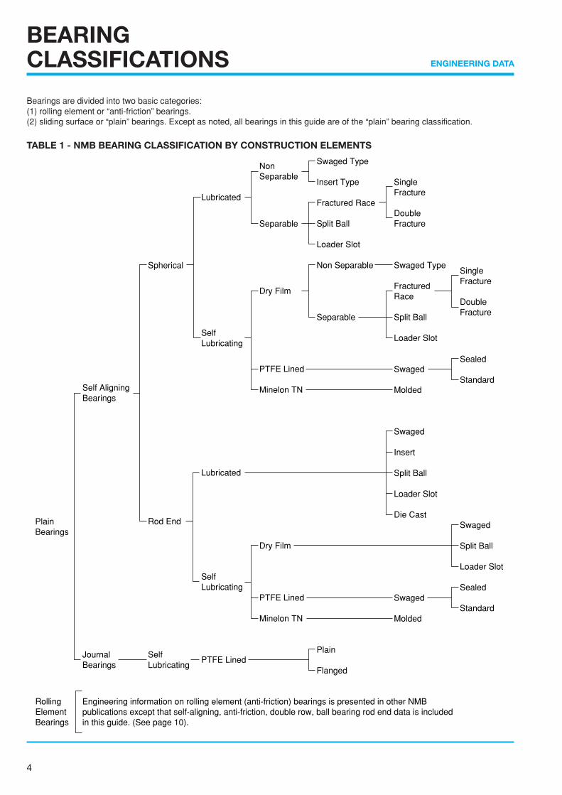
Bearings are divided into two basic categories:(1) rolling element or “anti-friction” bearings.(2) sliding surface or “plain” bearings. Except as noted, all bearings in this guide are of the “plain” bearing classification.
TABLE 1 - NMB BEARING CLASSIFICATION BY CONSTRUCTION ELEMENTS
Plain Bearings
Spherical
Rod End
Self Lubricating
Lubricated
Self Lubricating
Lubricated
Self Lubricating
PTFE Lined
Engineering information on rolling element (anti-friction) bearings is presented in other NMB publications except that self-aligning, anti-friction, double row, ball bearing rod end data is included in this guide. (See page 10).
Single Fracture
Double Fracture
Sealed
Standard
Rolling Element Bearings
Swaged
Split Ball
Loader Slot
Sealed
Standard
Non Separable
Separable
Dry Film
PTFE Lined
Minelon TN
Dry Film
PTFE Lined
Minelon TN
Self Aligning Bearings
Journal Bearings
Swaged Type
Insert Type
Fractured Race
Split Ball
Loader Slot
Non Separable
Separable
Plain
Flanged
Single Fracture
Double Fracture
Swaged Type
Fractured Race
Split Ball
Loader Slot
Swaged
Molded
Swaged
Insert
Split Ball
Loader Slot
Die Cast
Swaged
Molded
5
ENGINEERING DATA
CLASSIFICATION INCH SERIES METRIC SERIES
SPHERICAL Metal / Metal ABG ABG-V HABG HABG-V MBG-CR MBG-VCRBEARINGS ABW ABW-V ABY ABY-V MBW-CR MBW-VCR
ABK ABK-V HABK HABK-V MBY-CR MBY-VCRABC-G ABC-VG ABB ABB-S SBH SBWHABC-VA ABC-GA ABC-VGA AM SBW
PTFE lined ABT ABT-V ABWT ABWT-V SBTABYT ABYT-V HT HT-V MBT-V MBTHTY HTY-V WHT WHT-V MBWT-V MBWTHTL HTL-V WHTL WHTL-V MBYT-V MBYT
Minelon TN N/A BM
2 PIECE Metal / Metal AHM AHF N/AROD ENDS PTFE lined AHMT AHFT RBT-E RBT
3 PIECE Metal / Metal AR AR-E ARH ARH-E HR-E HRROD ENDS ARYM ARYF ARB ARB-E HRH-E HRH
AMM AMF
PTFE lined ART ART-E ARHT ARHT-E HRT-E HRTARYT ARYT-E ANM ANF HRHT-E HRHTARNM ARNF
4 PIECE Metal / Metal CAMR CAFR AMR AFR PR-E PRROD ENDS (insert type)
DIE CAST Metal / Metal N/A ERROD ENDS
MOLDED RACE Minelon TN CAMMR CAMFR RBM-E RBMROD ENDS
JOURNAL PTFE lined AJ AJF AHJ AHJF MJ MJFBEARINGS
BALL BEARING (Anti-friction) ABR-M ABR-F ABR-H ABR-S PBR-E PBRROD ENDS
•ROLLER BRGS (Anti-friction) ASR ASRD ASRDG.ASRDF ASRD-V N/A
•ROLLER BRG (Anti-friction) ARR-FFN ARR-MFN ARR-MFN-3 ARR-HFN N/A ROD ENDS ARR-SFN ARRD-HFN ARRD-SFN ARRE-M
ARRDE-M
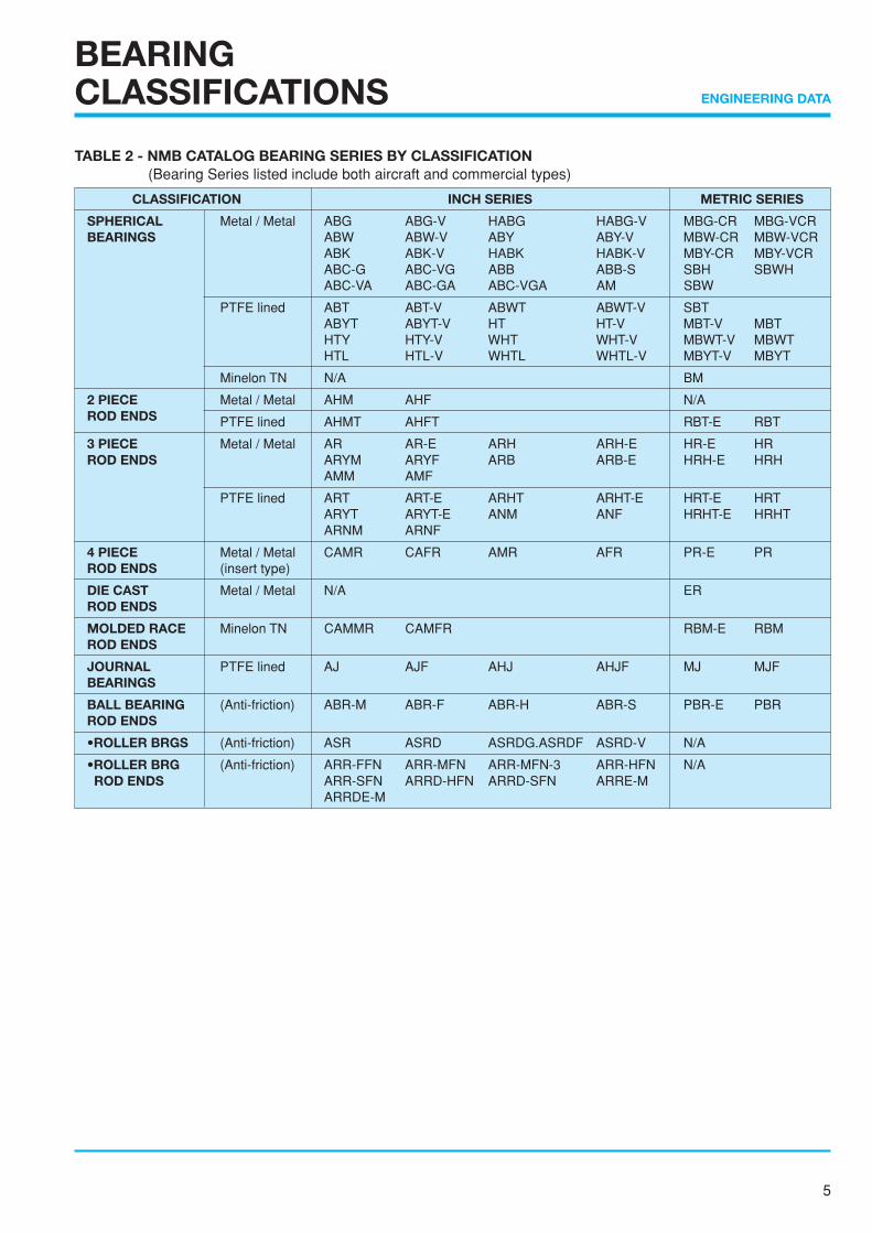
TABLE 2 - NMB CATALOG BEARING SERIES BY CLASSIFICATION(Bearing Series listed include both aircraft and commercial types)
BEARINGCLASSIFICATIONS
6
ENGINEERING DATA
BEARING TYPES ANDDETAILS OF CONSTRUCTION ENGINEERING DATA
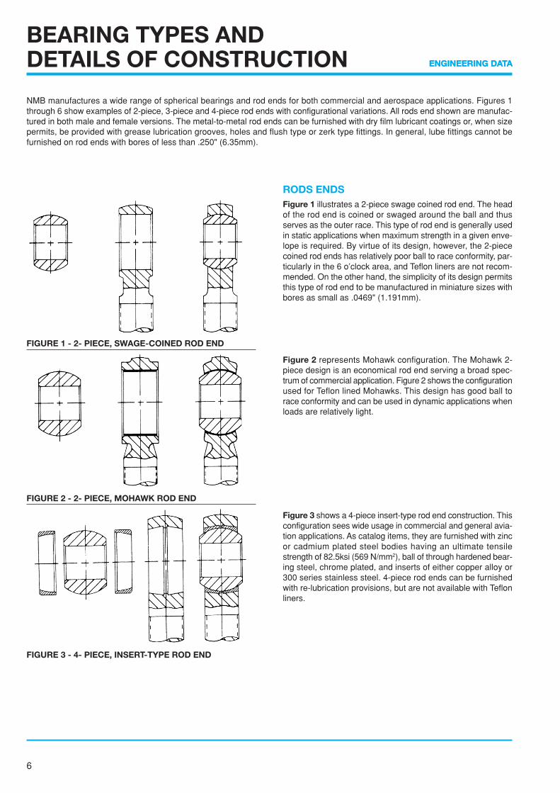
RODS ENDSFigure 1 illustrates a 2-piece swage coined rod end. The headof the rod end is coined or swaged around the ball and thusserves as the outer race. This type of rod end is generally usedin static applications when maximum strength in a given enve-lope is required. By virtue of its design, however, the 2-piececoined rod ends has relatively poor ball to race conformity, par-ticularly in the 6 o’clock area, and Teflon liners are not recom-mended. On the other hand, the simplicity of its design permitsthis type of rod end to be manufactured in miniature sizes withbores as small as .0469" (1.191mm).
Figure 2 represents Mohawk configuration. The Mohawk 2-piece design is an economical rod end serving a broad spec-trum of commercial application. Figure 2 shows the configurationused for Teflon lined Mohawks. This design has good ball torace conformity and can be used in dynamic applications whenloads are relatively light.
Figure 3 shows a 4-piece insert-type rod end construction. Thisconfiguration sees wide usage in commercial and general avia-tion applications. As catalog items, they are furnished with zincor cadmium plated steel bodies having an ultimate tensilestrength of 82.5ksi (569 N/mm2), ball of through hardened bear-ing steel, chrome plated, and inserts of either copper alloy or300 series stainless steel. 4-piece rod ends can be furnishedwith re-lubrication provisions, but are not available with Teflonliners.
NMB manufactures a wide range of spherical bearings and rod ends for both commercial and aerospace applications. Figures 1through 6 show examples of 2-piece, 3-piece and 4-piece rod ends with configurational variations. All rods end shown are manufac-tured in both male and female versions. The metal-to-metal rod ends can be furnished with dry film lubricant coatings or, when sizepermits, be provided with grease lubrication grooves, holes and flush type or zerk type fittings. In general, lube fittings cannot befurnished on rod ends with bores of less than .250" (6.35mm).
FIGURE 2 - 2- PIECE, MOHAWK ROD END
FIGURE 1 - 2- PIECE, SWAGE-COINED ROD END
FIGURE 3 - 4- PIECE, INSERT-TYPE ROD END
7
ENGINEERING DATA
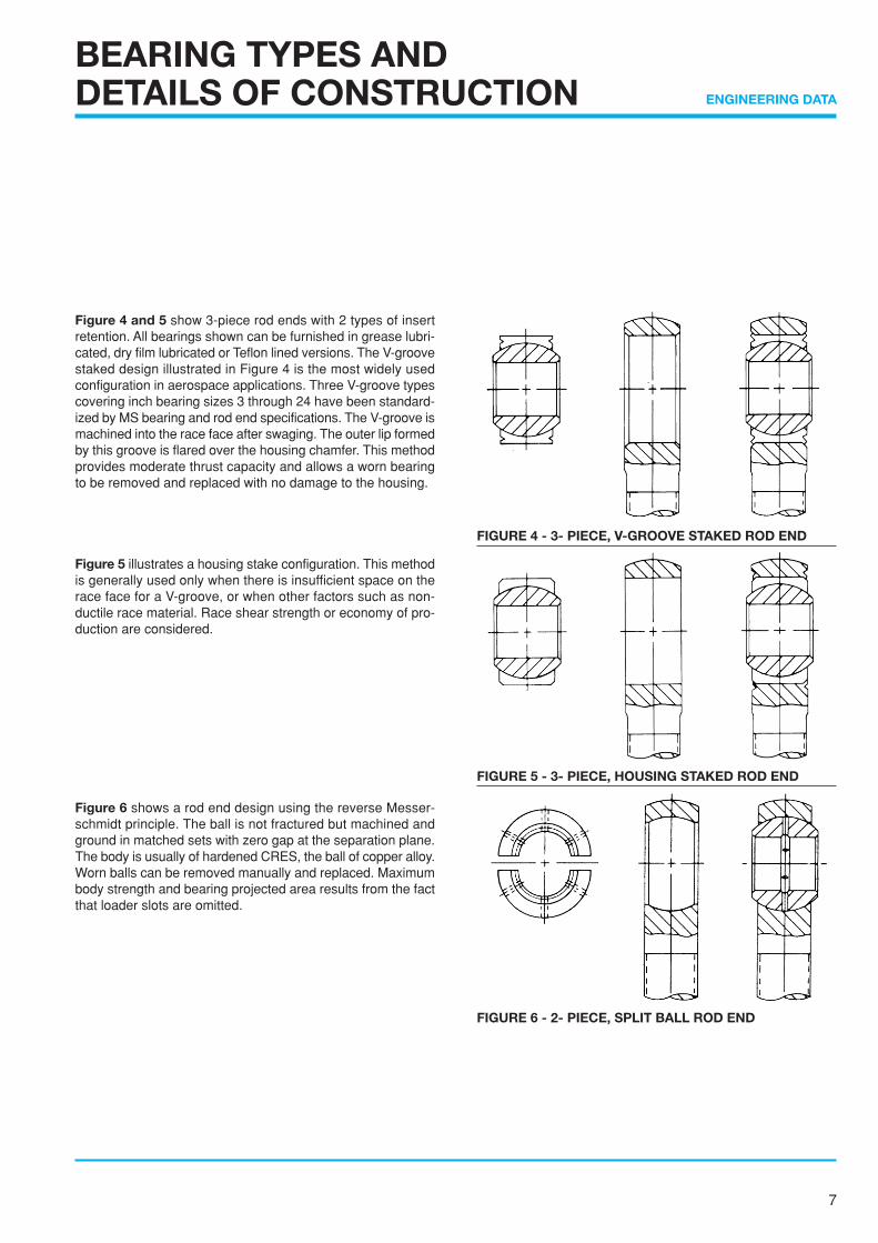
Figure 4 and 5 show 3-piece rod ends with 2 types of insertretention. All bearings shown can be furnished in grease lubri-cated, dry film lubricated or Teflon lined versions. The V-groovestaked design illustrated in Figure 4 is the most widely usedconfiguration in aerospace applications. Three V-groove typescovering inch bearing sizes 3 through 24 have been standard-ized by MS bearing and rod end specifications. The V-groove ismachined into the race face after swaging. The outer lip formedby this groove is flared over the housing chamfer. This methodprovides moderate thrust capacity and allows a worn bearingto be removed and replaced with no damage to the housing.
Figure 5 illustrates a housing stake configuration. This methodis generally used only when there is insufficient space on therace face for a V-groove, or when other factors such as non-ductile race material. Race shear strength or economy of pro-duction are considered.
Figure 6 shows a rod end design using the reverse Messer-schmidt principle. The ball is not fractured but machined andground in matched sets with zero gap at the separation plane.The body is usually of hardened CRES, the ball of copper alloy.Worn balls can be removed manually and replaced. Maximumbody strength and bearing projected area results from the factthat loader slots are omitted.
BEARING TYPES ANDDETAILS OF CONSTRUCTION
FIGURE 4 - 3- PIECE, V-GROOVE STAKED ROD END
FIGURE 5 - 3- PIECE, HOUSING STAKED ROD END
FIGURE 6 - 2- PIECE, SPLIT BALL ROD END
8
ENGINEERING DATA
BEARING TYPES ANDDETAILS OF CONSTRUCTION
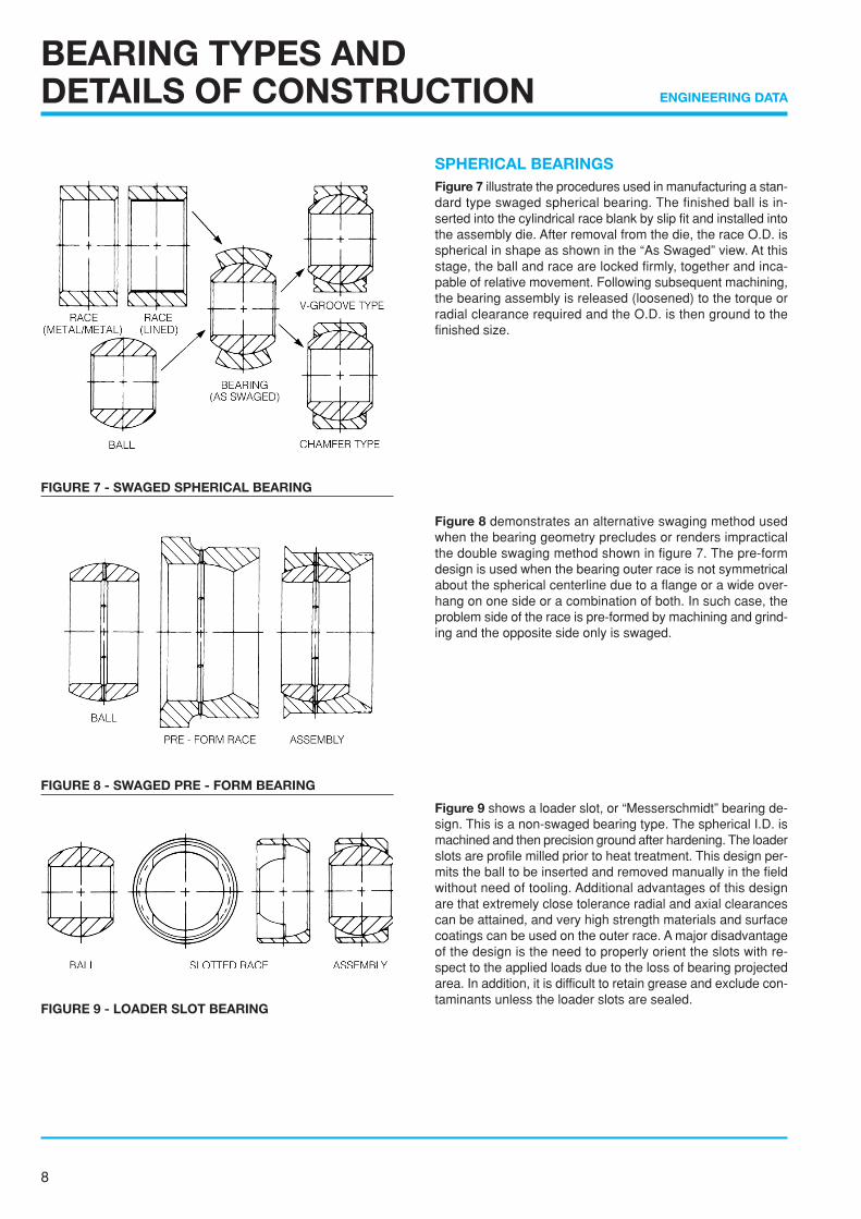
SPHERICAL BEARINGSFigure 7 illustrate the procedures used in manufacturing a stan-dard type swaged spherical bearing. The finished ball is in-serted into the cylindrical race blank by slip fit and installed intothe assembly die. After removal from the die, the race O.D. isspherical in shape as shown in the “As Swaged” view. At thisstage, the ball and race are locked firmly, together and inca-pable of relative movement. Following subsequent machining,the bearing assembly is released (loosened) to the torque orradial clearance required and the O.D. is then ground to thefinished size.
Figure 8 demonstrates an alternative swaging method usedwhen the bearing geometry precludes or renders impracticalthe double swaging method shown in figure 7. The pre-formdesign is used when the bearing outer race is not symmetricalabout the spherical centerline due to a flange or a wide over-hang on one side or a combination of both. In such case, theproblem side of the race is pre-formed by machining and grind-ing and the opposite side only is swaged.
Figure 9 shows a loader slot, or “Messerschmidt” bearing de-sign. This is a non-swaged bearing type. The spherical I.D. ismachined and then precision ground after hardening. The loaderslots are profile milled prior to heat treatment. This design per-mits the ball to be inserted and removed manually in the fieldwithout need of tooling. Additional advantages of this designare that extremely close tolerance radial and axial clearancescan be attained, and very high strength materials and surfacecoatings can be used on the outer race. A major disadvantageof the design is the need to properly orient the slots with re-spect to the applied loads due to the loss of bearing projectedarea. In addition, it is difficult to retain grease and exclude con-taminants unless the loader slots are sealed.
FIGURE 7 - SWAGED SPHERICAL BEARING
FIGURE 8 - SWAGED PRE - FORM BEARING
FIGURE 9 - LOADER SLOT BEARING
9
ENGINEERING DATA
BEARING TYPES ANDDETAILS OF CONSTRUCTION
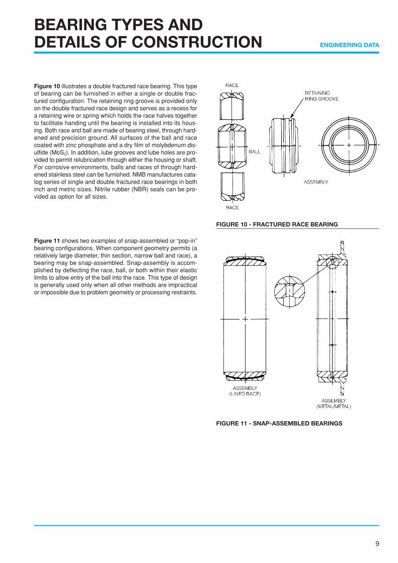
Figure 10 illustrates a double fractured race bearing. This typeof bearing can be furnished in either a single or double frac-tured configuration. The retaining ring groove is provided onlyon the double fractured race design and serves as a recess fora retaining wire or spring which holds the race halves togetherto facilitate handing until the bearing is installed into its hous-ing. Both race and ball are made of bearing steel, through hard-ened and precision ground. All surfaces of the ball and racecoated with zinc phosphate and a dry film of molybdenum dis-ulfide (MoS2). In addition, lube grooves and lube holes are pro-vided to permit relubrication through either the housing or shaft.For corrosive environments, balls and races of through hard-ened stainless steel can be furnished. NMB manufactures cata-log series of single and double fractured race bearings in bothinch and metric sizes. Nitrile rubber (NBR) seals can be pro-vided as option for all sizes.
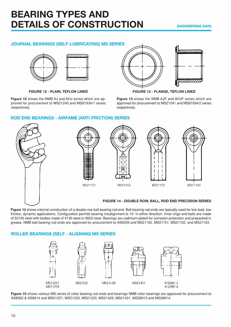
Figure 11 shows two examples of snap-assembled or “pop-in”bearing configurations. When component geometry permits (arelatively large diameter, thin section, narrow ball and race), abearing may be snap-assembled. Snap-assembly is accom-plished by deflecting the race, ball, or both within their elasticlimits to allow entry of the ball into the race. This type of designis generally used only when all other methods are impracticalor impossible due to problem geometry or processing restraints.
FIGURE 10 - FRACTURED RACE BEARING
FIGURE 11 - SNAP-ASSEMBLED BEARINGS
10
ENGINEERING DATA
BEARING TYPES ANDDETAILS OF CONSTRUCTION
JOURNAL BEARINGS (SELF-LUBRICATING) MS SERIES
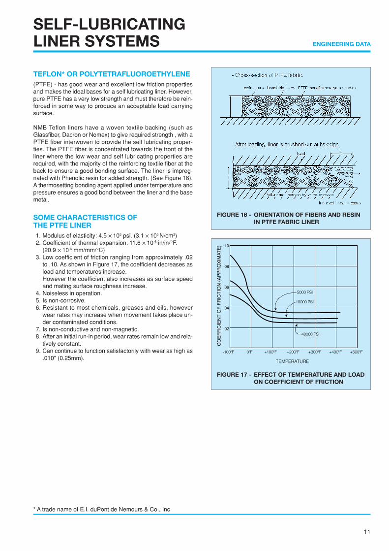
Figure 12 shows the NMB AJ and AHJ series which are ap-proved for procurement to MS21240 and MS81934/1 seriesrespectively.
Figure 13 shows the NMB AJF and AHJF series which areapproved for procurement to MS21241 and MS81934/2 seriesrespectively.
ROLLER BEARINGS (SELF - ALIGNING) MS SERIES
Figure 15 shows various MS series of roller bearing rod ends and bearings NMB roller bearings are approved for procurement toAS8952 & AS8914 and MS21221, MS21223, MS21220, MS21429, MS21431, MS28913 and MS28914.
FIGURE 12 - PLAIN, TEFLON LINED FIGURE 13 - FLANGE, TEFLON LINED
Figure 14 shows internal construction of a double row ball bearing rod end. Ball bearing rod ends are typically used for low load, lowfriction, dynamic applications. Configuration permits bearing misalignment to 10° in either direction. Inner rings and balls are madeof 52100 steel with bodies made of 4130 steel or 8620 steel. Bearings are cadmium plated for corrosion protection and prepacked ingrease. NMB ball bearing rod ends are approved for procurement to AS6039 and MS21150, MS21151, MS21152, and MS21153.
ROD END BEARINGS - AIRFAME (ANTI-FRICTION) SERIES
FIGURE 14 - DOUBLE ROW, BALL, ROD END PRECISION SERIES
11
ENGINEERING DATA
SELF-LUBRICATINGLINER SYSTEMS
TEFLON* OR POLYTETRAFLUOROETHYLENE(PTFE) - has good wear and excellent low friction propertiesand makes the ideal bases for a self lubricating liner. However,pure PTFE has a very low strength and must therefore be rein-forced in some way to produce an acceptable load carryingsurface.
NMB Teflon liners have a woven textile backing (such asGlassfiber, Dacron or Nomex) to give required strength , with aPTFE fiber interwoven to provide the self lubricating proper-ties. The PTFE fiber is concentrated towards the front of theliner where the low wear and self lubricating properties arerequired, with the majority of the reinforcing textile fiber at theback to ensure a good bonding surface. The liner is impreg-nated with Phenolic resin for added strength. (See Figure 16).A thermosetting bonding agent applied under temperature andpressure ensures a good bond between the liner and the basemetal.
SOME CHARACTERISTICS OFTHE PTFE LINER1. Modulus of elasticity: 4.5 ✕ 105 psi. (3.1 ✕ 105 N/cm2)2. Coefficient of thermal expansion: 11.6 ✕ 10-6 in/in/°F.
(20.9 ✕ 10-6 mm/mm/°C)3. Low coefficient of friction ranging from approximately .02
to .10. As shown in Figure 17, the coefficient decreases asload and temperatures increase.However the coefficient also increases as surface speedand mating surface roughness increase.
4. Noiseless in operation.5. Is non-corrosive.6. Resistant to most chemicals, greases and oils, however
wear rates may increase when movement takes place un-der contaminated conditions.
7. Is non-conductive and non-magnetic.8. After an initial run-in period, wear rates remain low and rela-
tively constant.9. Can continue to function satisfactorily with wear as high as
.010" (0.25mm).
* A trade name of E.I. duPont de Nemours & Co., Inc
FIGURE 16 - ORIENTATION OF FIBERS AND RESININ PTFE FABRIC LINER
CO
EF
FIC
IEN
T O
F F
RIC
TIO
N (
AP
PR
OX
IMAT
E) .10
.08
.06
.04
.02
FIGURE 17 - EFFECT OF TEMPERATURE AND LOADON COEFFICIENT OF FRICTION
12
ENGINEERING DATA
SELF-LUBRICATINGLINER SYSTEMS
WE
AR
- IN
CH
ES
WE
AR
- IN
CH
ES
0
0 25 50 75 100 125 150
50 100 150 200 250 300
.001
.002
.003
.004
.005
.006
.001
.002
.003
.004
.005
.006
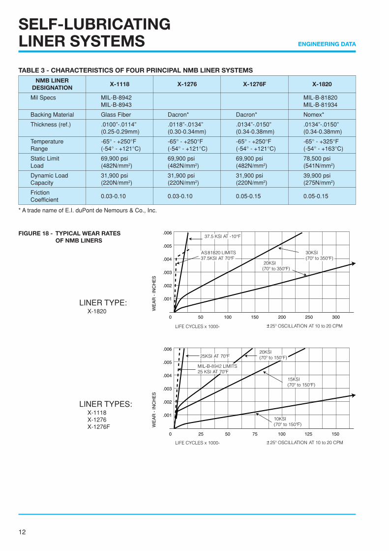
FIGURE 18 - TYPICAL WEAR RATESOF NMB LINERS
LINER TYPE: X-1820
LINER TYPES: X-1118 X-1276 X-1276F
TABLE 3 - CHARACTERISTICS OF FOUR PRINCIPAL NMB LINER SYSTEMS
NMB LINERX-1118 X-1276 X-1276F X-1820
DESIGNATION
Mil Specs MIL-B-8942 MIL-B-81820MIL-B-8943 MIL-B-81934
Backing Material Glass Fiber Dacron* Dacron* Nomex*
Thickness (ref.) .0100”-.0114” .0118”-.0134” .0134”-.0150” .0134”-.0150”(0.25-0.29mm) (0.30-0.34mm) (0.34-0.38mm) (0.34-0.38mm)
Temperature -65° - +250°F -65° - +250°F -65° - +250°F -65° - +325°FRange (-54° - +121°C) (-54° - +121°C) (-54° - +121°C) (-54° - +163°C)
Static Limit 69,900 psi 69,900 psi 69,900 psi 78,500 psiLoad (482N/mm2) (482N/mm2) (482N/mm2) (541N/mm2)
Dynamic Load 31,900 psi 31,900 psi 31,900 psi 39,900 psiCapacity (220N/mm2) (220N/mm2) (220N/mm2) (275N/mm2)
Friction0.03-0.10 0.03-0.10 0.05-0.15 0.05-0.15
Coefficient
* A trade name of E.I. duPont de Nemours & Co., Inc.
13
ENGINEERING DATA
DY
NA
MIC
LO
AD
FA
CT
OR
302520
15
10
54
3
2
1.5
1
0.8
0.60.5
BEARING LIFE-CYCLES
1.5 21 3 4 5 1.5 21 3 4 5 1.5 21 13 4 5
SELF-LUBRICATINGLINER SYSTEMS
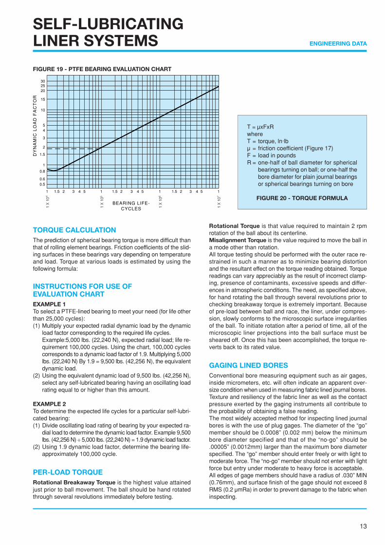
TORQUE CALCULATIONThe prediction of spherical bearing torque is more difficult thanthat of rolling element bearings. Friction coefficients of the slid-ing surfaces in these bearings vary depending on temperatureand load. Torque at various loads is estimated by using thefollowing formula:
INSTRUCTIONS FOR USE OFEVALUATION CHARTEXAMPLE 1To select a PTFE-lined bearing to meet your need (for life otherthan 25,000 cycles):(1) Multiply your expected radial dynamic load by the dynamic
load factor corresponding to the required life cycles.Example:5,000 lbs. (22,240 N), expected radial load; life re-quirement 100,000 cycles. Using the chart, 100,000 cyclescorresponds to a dynamic load factor of 1.9. Multiplying 5,000lbs. (22,240 N) By 1.9 = 9,500 lbs. (42,256 N), the equivalentdynamic load.
(2) Using the equivalent dynamic load of 9,500 lbs. (42,256 N),select any self-lubricated bearing having an oscillating loadrating equal to or higher than this amount.
EXAMPLE 2To determine the expected life cycles for a particular self-lubri-cated bearing:(1) Divide oscillating load rating of bearing by your expected ra-
dial load to determine the dynamic load factor. Example 9,500lbs. (42,256 N) ÷ 5,000 lbs. (22,240 N) = 1.9 dynamic load factor.
(2) Using 1.9 dynamic load factor, determine the bearing life-approximately 100,000 cycle.
PER-LOAD TORQUERotational Breakaway Torque is the highest value attainedjust prior to ball movement. The ball should be hand rotatedthrough several revolutions immediately before testing.
Rotational Torque is that value required to maintain 2 rpmrotation of the ball about its centerline.Misalignment Torque is the value required to move the ball ina mode other than rotation.All torque testing should be performed with the outer race re-strained in such a manner as to minimize bearing distortionand the resultant effect on the torque reading obtained. Torquereadings can vary appreciably as the result of incorrect clamp-ing, presence of contaminants, excessive speeds and differ-ences in atmospheric conditions. The need, as specified above,for hand rotating the ball through several revolutions prior tochecking breakaway torque is extremely important. Becauseof pre-load between ball and race, the liner, under compres-sion, slowly conforms to the microscopic surface irregularitiesof the ball. To initiate rotation after a period of time, all of themicroscopic liner projections into the ball surface must besheared off. Once this has been accomplished, the torque re-verts back to its rated value.
GAGING LINED BORESConventional bore measuring equipment such as air gages,inside micrometers, etc. will often indicate an apparent over-size condition when used in measuring fabric lined journal bores.Texture and resiliency of the fabric liner as well as the contactpressure exerted by the gaging instruments all contribute tothe probability of obtaining a false reading.The most widely accepted method for inspecting lined journalbores is with the use of plug gages. The diameter of the “go”member should be 0.0008” (0.002 mm) below the minimumbore diameter specified and that of the “no-go” should be.00005” (0.0012mm) larger than the maximum bore diameterspecified. The “go” member should enter freely or with light tomoderate force. The “no-go” member should not enter with lightforce but entry under moderate to heavy force is acceptable.All edges of gage members should have a radius of .030” MIN(0.76mm), and surface finish of the gage should not exceed 8RMS (0.2 µmRa) in order to prevent damage to the fabric wheninspecting.
T = µxFxRwhereT = torque, ln·lbµ = friction coefficient (Figure 17)F = load in poundsR = one-half of ball diameter for spherical
bearings turning on ball; or one-half thebore diameter for plain journal bearingsor spherical bearings turning on bore
FIGURE 20 - TORQUE FORMULA
FIGURE 19 - PTFE BEARING EVALUATION CHART
14
ENGINEERING DATA
SELF-LUBRICATINGLINER SYSTEMS
FACTORS AFFECTING THE SELECTION, PERFORMANCE AND EVALUATION OFPTFE-LINED SPHERICAL, ROD END JOURNAL BEARINGS
An answer to situations where the performance envelopecannot be covered by metal to metal bearings is to con-sider PTFE-lined bearings. Here, the lubricant configura-tion is such that it functions as the load carrying elementof the bearing, as represented by the liner systems cur-rently in use. PTFE bearings may be specified under all orsome of the following situations:
1. Where lubrication is undesirable, difficult to perform, or im-poss ib le .
2. Where loads are high and angular movement is low. Underthese circumstances, rolling element bearings fail rapidly.
3. Where space is limited. A PTFE-lined bearing in high load-low speed environments is usually much smaller in sizethan a rolling element bearing.
4. Where vibration is present. A PTFE-lined bearing is morelikely to accept vibration than is a rolling element bearing.
5. Where temperature of the environment renders greasingunfeasible.
6. Where a joint must remain static for extended long periodsof time before movement is initiated.
7. Where friction in a greased bearing would be so high as torender the joint area unless after a limited number of cyclesor impose an unacceptable fatigue situation.
8. Where, in static joints, fretting is a problem.
While PTFE-lined bearings can do an excellent job in manyareas, there have been areas of misapplication. Also, thereexist some misunderstandings regarding life and failureas applied to hardware of this type. We may define someof these concepts as follows:
1. The PTFE-lined bearing starts life with a finite rotationalpre-load torque or clearance.
2. This rotational pre-load torque always decreases with bear-ing usage and clearance always increases with usage.
3. A bearing may be said to have failed if the rotational pre-load torque drops below some specified value. This is al-ways a systems application characteristic.
4. A bearing may be said to have failed when the clearancegenerated by wear exceeds some specified value. This,again, is always some specified systems characteristic.
5. A bearing may be said to have failed if the liner wearsthrough enough to permit the ball to contact the race.
6. No bearing, including PTFE-lined bearings, will last forever.The “Lifetime” lubrication concept applies to the bearingalone, not to the end usage item.
7. The presence of liner debris on a bearing is not a definitiveindication of failure.
8. PTFE-lined bearings tend to telegraph their impending fail-ure by increased radial and axial play.
15
ENGINEERING DATA
SELF-LUBRICATINGLINER SYSTEMS
When evaluating the probable service life of a PTFE-linedbearing application, there are some factors that do notappear in the PV = K relationship. Some considerationsfor a given application might include:
1. Surface sliding speed.
2. Maximum ambient temperature.
3. Size of the heat sink.
4. Acceptable friction levels.
5. Load per unit of area, or liner stress level.
6. Mode of load application; i.e., the duty cycle.
7. Service alignment accuracy, particularly with respect tosleeve and flanged bearings.
8. Surrounding atmosphere.
9. Tolerable wear rate.
10. Surface finish of the bearing mating shaft and the shaftmaterial.
Cost is not included in the above list since it does not af-fect the serviceability of any bearing. Higher individualbearing costs may many times result in a more economi-cal or lower priced finished assembly.
Other aspects of applying PTFE-lined bearings relate tomany obscure factors. The airframe industry is a case inparticular. They readily accept the L10 life concept in evalu-ating rolling element bearings but tend to reject it in linedbearings. In dealing with the troubleshooting relating tolined bearings at the user level, we may summarize mostof them as follows:
1. Customers specify bearings to certain generalized specifica-tions which may or may not reflect end usage requirements.
2. Customers very often have no idea, nor can they definewhat loads or loading situations the bearings may be sub-jected to during the design stage.
3. Continued upgrading of TBO performance on the part ofusers may not be consistent with established structuralenvelopes.
4. A marked difference exists between what is acceptable onmilitary aircraft versus civil aircraft. Apparently specifica-tion writers overlook this aspect entirely.
5. Most customers and users do not realize that life in a linedbearing is limited. They accept this fact on clutches andbrakes, but they apparently cannot see the similarity withrespect to lined bearings.
6. No acceptable criteria have been established with respectto design or acceptable life for this type of bearing. There-fore it is almost impossible for a bearing supplier to initiateall-encompassing test programs.
7. Many bearings are removed and replaced because of de-tectable play between ball and race. Some bearings havebeen removed that still have specification pre-load torque.We must conclude that the potential service life of the bear-ing is not being used.
8. Confusion exists with regard to liner wear. The term “ex-truded liner” often noted on field UR’s is not sufficiently de-finitive. Wear debris is normal to this type of bearing andmust be differentiated from true liner failure.
9. The term “dynamic load rating” or “oscillating load rating”should not be used to select a bearing for an application.These ratings have no relationship to actual applicationsand relate to a qualification condition only.
10. Many line bearings are removed because of fretting be-tween the bearing outer race and the adjacent structure.The use of metal-to-metal bearings will not eliminate thisproblem. This situation can be cured only by proper selec-tion of materials and interface surface finishes.
16
ENGINEERING DATA
GREASE AND DRYLUBRICANTS
GREASEWhen using a fluid (grease/oil) type lubricant, optimum lubri-cation is achieved when the moving member is supported by ahydrodynamic film. This hydrodynamic film is best generatedunder operating conditions of light loads and high speed rota-tion as characterized by typical ball bearing applications. Themost common lubricated spherical bearing application, how-ever, is typified by relatively high loads and slow oscillation,seldom by steady rotational movement.
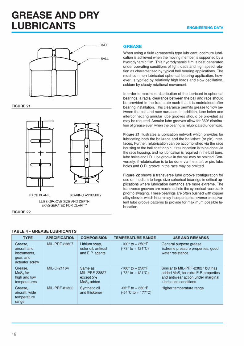
In order to maximize distribution of the lubricant in sphericalbearings, a radial clearance between the ball and race shouldbe provided in the free state such that it is maintained afterbearing installation. This clearance permits grease to flow be-tween the ball and race surfaces. In addition, lube holes andinterconnecting annular lube grooves should be provided asmay be required. Annular lube grooves allow for 360° distribu-tion of grease even when the bearing is relubricated under load.
Figure 21 illustrates a lubrication network which provides forlubricating both the ball/race and the ball/shaft (or pin) inter-faces. Further, relubrication can be accomplished via the racehousing or the ball shaft or pin. If relubrication is to be done viathe race housing, and no lubrication is required in the ball bore,lube holes and I.D. lube groove in the ball may be omitted. Con-versely, if relubrication is to be done via the shaft or pin, lubeholes and O.D. groove in the race may be omitted.
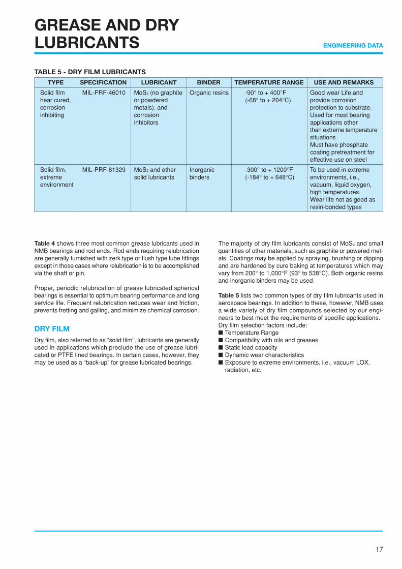
Figure 22 shows a transverse lube groove configuration foruse on medium to large size spherical bearings in critical ap-plications where lubrication demands are more extreme. Thetransverse grooves are machined into the cylindrical race blankprior to swaging. These bearings are often bushed with copperalloy sleeves which in turn may incorporate transverse or equiva-lent lube groove patterns to provide for maximum possible lu-brication.
TABLE 4 - GREASE LUBRICANTS
TYPE SPECIFICATION COMPOSISION TEMPERATURE RANGE USE AND REMARKS
Grease, MIL-PRF-23827 Lithium soap, -100° to + 250°F General purpose grease,aircraft and ester oil, antirust (-73° to + 121°C) Extreme pressure properties, goodinstruments, and E.P. agents water resistance.gear, andactuator screw
Grease, MIL-G-21164 Same as -100° to + 250°F Similar to MIL-PRF-23827 but hasMoS2 for MIL-PRF-23827 (-73° to + 121°C) added MoS2 for extra E.P. propertieshigh and low except 5% and antiwear action under marginaltemperatures MoS2 added lubrication conditions
Grease, MIL-PRF-81322 Synthetic oil -65°F to + 350°F Higher temperature rangeaircraft, wide and thickener (-54°C to + 177°C)temperaturerange
FIGURE 21
FIGURE 22
17
ENGINEERING DATA
GREASE AND DRYLUBRICANTS
Table 4 shows three most common grease lubricants used inNMB bearings and rod ends. Rod ends requiring relubricationare generally furnished with zerk type or flush type lube fittingsexcept in those cases where relubrication is to be accomplishedvia the shaft or pin.
Proper, periodic relubrication of grease lubricated sphericalbearings is essential to optimum bearing performance and longservice life. Frequent relubrication reduces wear and friction,prevents fretting and galling, and minimize chemical corrosion.
DRY FILMDry film, also referred to as “solid film”, lubricants are generallyused in applications which preclude the use of grease lubri-cated or PTFE lined bearings. In certain cases, however, theymay be used as a “back-up” for grease lubricated bearings.
The majority of dry film lubricants consist of MoS2 and smallquantities of other materials, such as graphite or powered met-als. Coatings may be applied by spraying, brushing or dippingand are hardened by cure baking at temperatures which mayvary from 200° to 1,000°F (93° to 538°C). Both organic resinsand inorganic binders may be used.
Table 5 lists two common types of dry film lubricants used inaerospace bearings. In addition to these, however, NMB usesa wide variety of dry film compounds selected by our engi-neers to best meet the requirements of specific applications.Dry film selection factors include:■ Temperature Range■ Compatibility with oils and greases■ Static load capacity■ Dynamic wear characteristics■ Exposure to extreme environments, i.e., vacuum LOX,
radiation, etc.
TABLE 5 - DRY FILM LUBRICANTS
TYPE SPECIFICATION LUBRICANT BINDER TEMPERATURE RANGE USE AND REMARKS
Solid film MIL-PRF-46010 MoS2 (no graphite Organic resins -90° to + 400°F Good wear Life andhear cured, or powdered (-68° to + 204°C) provide corrosioncorrosion metals), and protection to substrate.inhibiting corrosion Used for most bearing
inhibitors applications otherthan extreme temperaturesituationsMust have phosphatecoating pretreatment foreffective use on steel
Solid film, MIL-PRF-81329 MoS2 and other Inorganic -300° to + 1200°F To be used in extremeextreme solid lubricants binders (-184° to + 648°C) environments, i.e.,environment vacuum, liquid oxygen,
high temperatures.Wear life not as good asresin-bonded types
18
ENGINEERING DATA
LOCKING DEVICES,KEYS AND KEYWAYS
NAS 1193 KEY
NAS 513 KEY Thread D E FSize +.005 +.005 +.000
➁ -.000 -.000 -.005
.2500 .056 .062 .201
.3125 .056 .062 .260
.3750 .056 .093 .311
.4375 .069 .093 .370
.5000 .069 .093 .436
.5625 .077 .125 .478
.6250 .077 .125 .541
.7500 .077 .125 .663
.8750 .086 .156 .7771.0000 .094 .156 .900
1.1250 .094 .187 1.0101.2500 .116 .187 1.1361.3750 .116 .250 1.2361.5000 .116 .250 1.3611.6250 .129 .250 1.477
1.7500 .129 .312 1.5891.8750 .129 .312 1.7142.0000 .129 .312 1.8392.1250 .129 .312 1.9552.2500 .129 .312 2.080
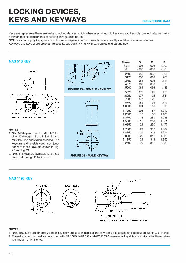
NOTES:1. NAS 1193 keys are for positive indexing. They are used in applications in which a fine adjustment is required, within .001 inches.2. These keys can be used in conjunction with NAS 513, NAS 559 and AS81935/3 keyways or keyslots are available for thread sizes
1/4 through 2-1/4 inches.
NOTES:1. NAS 513 keys are used on MIL-B-81935
size -10 through -16 and MS21151 andMS21153 rod ends when optioned. Thekeyways and keyslots used in conjunc-tion with these keys are shown in Fig.23 and Fig. 24.
➁ NAS 513 keys are available for threadsizes 1/4 through 2-1/4 inches.
Keys are represented here are metallic locking devices which, when assembled into keyways and keyslots, prevent relative motionbetween mating components of bearing linkage assemblies.NMB does not supply keys, nuts or lock wire as separate items. These items are readily available from other sources.Keyways and keyslot are optional. To specify, add suffix “W” to NMB catalog rod end part number.
FIGURE 23 - FEMALE KEYSLOT
FIGURE 24 - MALE KEYWAY
19
ENGINEERING DATA
LOCKING DEVICES,KEYS AND KEYWAYS
Thread D E F RSize +.005 +.005 +.000 ±.010➀ -.000 -.000 -.005
.2500 .056 .062 .201 .255
.3125 .056 .062 .260 .255
.3750 .056 .093 .311 .255
.4375 .069 .093 .370 .255
.5000 .069 .093 .436 .255
.5625 .077 .125 .478 .255
.6250 .077 .125 .541 .255
.7500 .077 .125 .663 .255
.8750 .086 .156 .777 .3181.0000 .094 .156 .900 .318
1.1250 .094 .187 1.010 .3821.2500 .116 .187 1.136 .3821.3750 .116 .250 1.236 .4451.5000 .116 .250 1.361 .4451.6250 .129 .250 1.477 .445
1.7500 .129 .312 1.589 .5081.8750 .129 .312 1.714 .5082.0000 .129 .312 1.839 .5082.1250 .129 .312 1.955 .5082.2500 .129 .312 1.080 .508
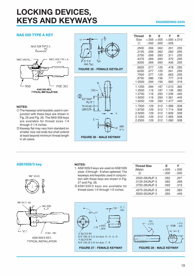
AS81935/3 key NOTES:1. AS81935/3 keys are used on AS81935
sizes -3 through - 8 when optioned. Thekeyways and keyslots used in conjunc-tion with these keys are shown in Fig.27 and Fig. 28.
➁AS81935/3 keys are available forthread sizes 1/4 through 1/2 inches.
Thread Size E F(Male) +.005 +.000
➁ -.000 -.005
.2500-28UNJF-3 .062 .207
.3125-24UNJF-3 .062 .268
.3750-28UNJF-3 .093 .319
.4375-20UNJF-3 .093 .383
.5000-20UNJF-3 .093 .445
NAS 559 TYPE A KEY
NOTES:➀The keyways and keyslots used in con-
junction with these keys are shown inFig. 25 and Fig. 26. The NAS 559 keysare available for thread sizes 1/4through 2-1/4 inches.
➁Keyway flat may vary from standard onsmaller size rod ends but shall extendat least beyond minimum thread lengthin all cases.
FIGURE 27 - FEMALE KEYWAY FIGURE 28 - MALE KEYWAY
FIGURE 25 - FEMALE KEYSLOT
FIGURE 26 - MALE KEYWAY
AS81935/3 KEY,TYPICAL INSTALLATION
.255±.010 +.015
-.000
20
ENGINEERING DATA
BEARING INSTALLATIONAND RETENTION
GENERALA bearing in the free state is not a functioning bearing. Its per-formance begins only after its has been installed into its endassembly, and the methods, fits and forces applied in installa-tion will often determine its success or failure in service.
A surprising percentage of early bearing failures can be traceddirectly to improper mounting conditions. Some examples offrequently occurring installation errors are:(1) excessive interference fit between housing bore and bear-ing O.D. (2) improperly designed staking tools. (3) excessivestaking forces applied.
The following pages are offered not as a comprehensive guideto answer all questions regarding fits, installation, retention,etc., but rather to point out to the bearing user certain areasthat require attention and consideration if the installation is toprovide for optimum bearing performance and life.
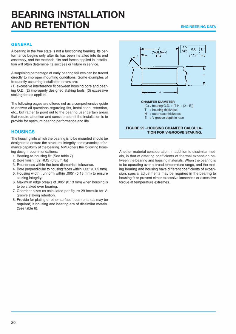
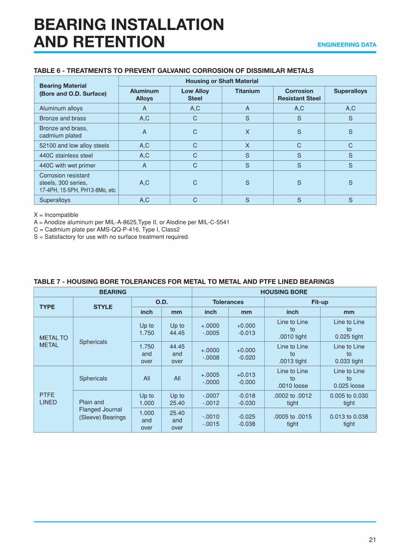
HOUSINGSThe housing into which the bearing is to be mounted should bedesigned to ensure the structural integrity and dynamic perfor-mance capability of the bearing. NMB offers the following hous-ing design recommendations:1. Bearing-to-housing fit: (See table 7).2. Bore finish : 32 RMS (0.8 µmRa)3. Roundness within the bore diametrical tolerance.4. Bore perpendicular to housing faces within .002" (0.05 mm).5. Housing width : uniform within .005" (0.13 mm) to ensure
staking integrity.6. Maximum edge breaks of .005" (0.13 mm) when housing is
to be staked over bearing.7. Chamber sizes as calculated per figure 29 formula for V-
groove staking retention.8. Provide for plating or other surface treatments (as may be
required) if housing and bearing are of dissimilar metals.(See table 6).
Another material consideration, in addition to dissimilar met-als, is that of differing coefficients of thermal expansion be-tween the bearing and housing materials. When the bearing isto be operating over a broad temperature range, and the mat-ing bearing and housing have different coefficients of expan-sion, special adjustments may be required in the bearing tohousing fit to prevent either excessive looseness or excessivetorque at temperature extremes.
FIGURE 29 - HOUSING CHAMFER CALCULA-TION FOR V-GROOVE STAKING.
CHAMFER DIAMETER(C) = bearing O.D. + [T-H + (2 ✕ E)]T = housing thicknessH = outer race thicknessE = V groove depth in race
21
ENGINEERING DATA
BEARING INSTALLATIONAND RETENTION
TABLE 6 - TREATMENTS TO PREVENT GALVANIC CORROSION OF DISSIMILAR METALS
Bearing MaterialHousing or Shaft Material
Aluminum Low Alloy Titanium Corrosion Superalloys(Bore and O.D. Surface)Alloys Steel Resistant Steel
Aluminum alloys A A,C A A,C A,C
Bronze and brass A,C C S S S
Bronze and brass,cadmium plated
A C X S S
52100 and low alloy steels A,C C X C C
440C stainless steel A,C C S S S
440C with wet primer A C S S S
Corrosion resistantsteels, 300 series, A,C C S S S17-4PH, 15-5PH, PH13-8Mo, etc
Superalloys A,C C S S S
X = IncompatibleA = Anodize aluminum per MIL-A-8625,Type II, or Alodine per MIL-C-5541C = Cadmium plate per AMS-QQ-P-416, Type I, Class2S = Satisfactory for use with no surface treatment required.
TABLE 7 - HOUSING BORE TOLERANCES FOR METAL TO METAL AND PTFE LINED BEARINGS
BEARING HOUSING BORE
TYPE STYLEO.D. Tolerances Fit-up
inch mm inch mm inch mm
Up to Up to +.0000 +0.000Line to Line Line to Line
1.750 44.45 -.0005 -0.013to to
METAL TOSphericals
.0010 tight 0.025 tightMETAL 1.750 44.45
+.0000 +0.000Line to Line Line to Line
and and-.0008 -0.020
to toover over .0013 tight 0.033 tight
+.0005 +0.013Line to Line Line to Line
Sphericals All All-.0000 -0.000
to to.0010 loose 0.025 loose
PTFE Up to Up to -.0007 -0.018 .0002 to .0012 0.005 to 0.030LINED 1.000 25.40 -.0012 -0.030 tight tight
1.000 25.40-.0010 -0.025 .0005 to .0015 0.013 to 0.038
and and-.0015 -0.038 tight tight
over over
Plain andFlanged Journal(Sleeve) Bearings
22
ENGINEERING DATA
BEARING INSTALLATIONAND RETENTION
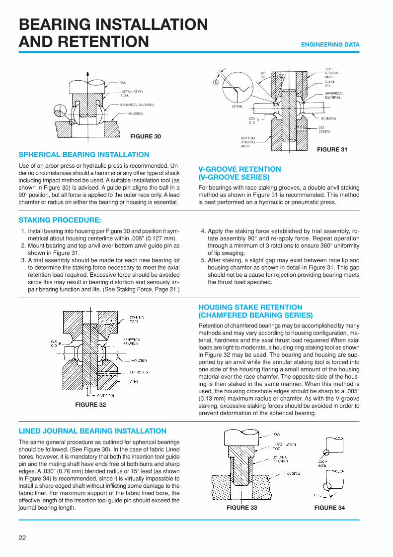
SPHERICAL BEARING INSTALLATIONUse of an arbor press or hydraulic press is recommended. Un-der no circumstances should a hammer or any other type of shockincluding impact method be used. A suitable installation tool (asshown in Figure 30) is advised. A guide pin aligns the ball in a90° position, but all force is applied to the outer race only. A leadchamfer or radius on either the bearing or housing is essential.
V-GROOVE RETENTION(V-GROOVE SERIES)For bearings with race staking grooves, a double anvil stakingmethod as shown in Figure 31 is recommended. This methodis best performed on a hydraulic or pneumatic press.
STAKING PROCEDURE:1. Install bearing into housing per Figure 30 and position it sym-
metrical about housing centerline within .005" (0.127 mm).2. Mount bearing and top anvil over bottom anvil guide pin as
shown in Figure 31.3. A trial assembly should be made for each new bearing lot
to determine the staking force necessary to meet the axialretention load required. Excessive force should be avoidedsince this may result in bearing distortion and seriously im-pair bearing function and life. (See Staking Force, Page 21.)
4. Apply the staking force established by trial assembly, ro-tate assembly 90° and re-apply force. Repeat operationthrough a minimum of 3 rotations to ensure 360° uniformityof lip swaging.
5. After staking, a slight gap may exist between race lip andhousing chamfer as shown in detail in Figure 31. This gapshould not be a cause for rejection providing bearing meetsthe thrust load specified.
HOUSING STAKE RETENTION(CHAMFERED BEARING SERIES)Retention of chamfered bearings may be accomplished by manymethods and may vary according to housing configuration, ma-terial, hardness and the axial thrust load requiered When axialloads are light to moderate, a housing ring staking tool as shownin Figure 32 may be used. The bearing and housing are sup-ported by an anvil while the annular staking tool is forced intoone side of the housing flaring a small amount of the housingmaterial over the race chamfer. The opposite side of the hous-ing is then staked in the same manner. When this method isused, the housing crosshole edges should be sharp to a .005"(0.13 mm) maximum radius or chamfer. As with the V-groovestaking, excessive staking forces should be avoided in order toprevent deformation of the spherical bearing.
LINED JOURNAL BEARING INSTALLATIONThe same general procedure as outlined for spherical bearingsshould be followed. (See Figure 30). In the case of fabric Linedbores, however, it is mandatory that both the insertion tool guidepin and the mating shaft have ends free of both burrs and sharpedges. A .030” (0.76 mm) blended radius or 15° lead (as shownin Figure 34) is recommended, since it is virtually impossible toinstall a sharp edged shaft without inflicting some damage to thefabric liner. For maximum support of the fabric lined bore, theeffective length of the insertion tool guide pin should exceed thejournal bearing length.
FIGURE 30
FIGURE 31
FIGURE 32
FIGURE 33 FIGURE 34
➄
23
ENGINEERING DATA
BEARING INSTALLATIONAND RETENTION
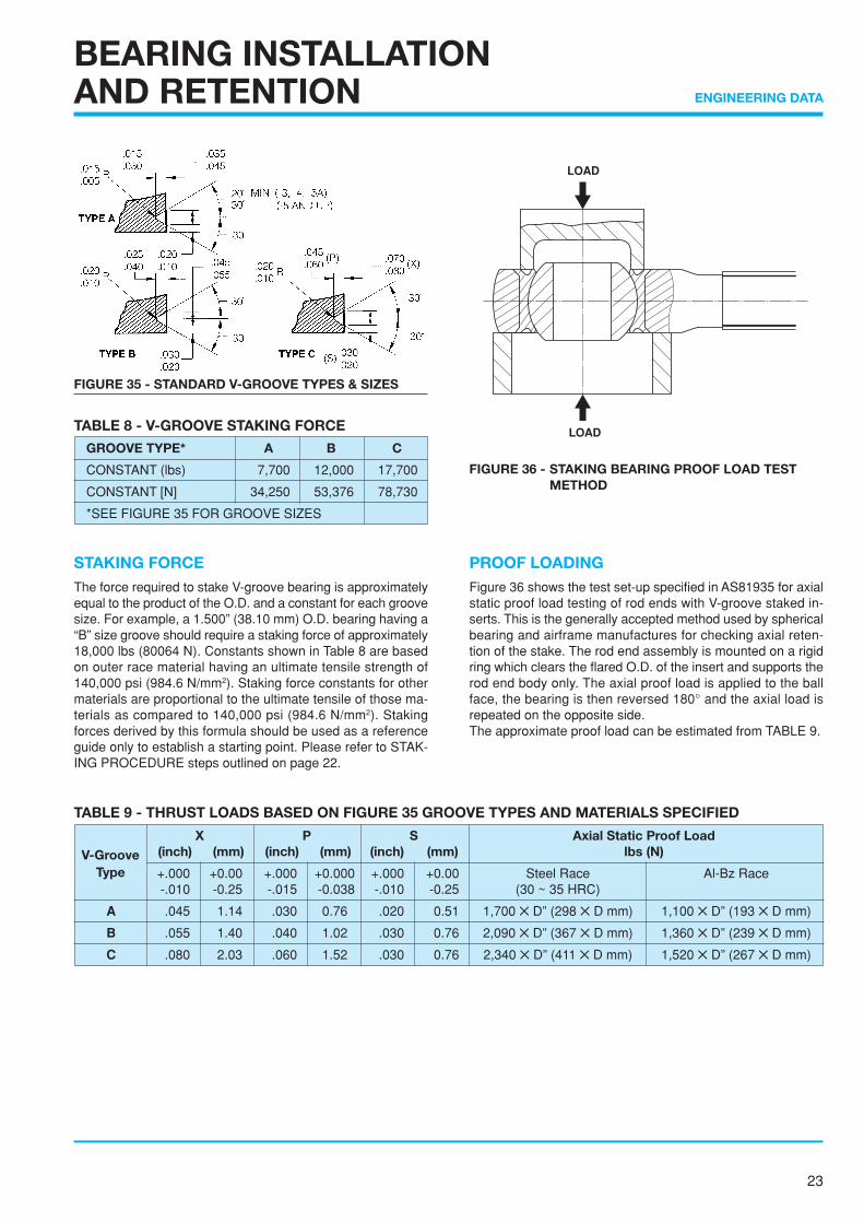
TABLE 8 - V-GROOVE STAKING FORCE
GROOVE TYPE* A B C
CONSTANT (lbs) 7,700 12,000 17,700
CONSTANT [N] 34,250 53,376 78,730
*SEE FIGURE 35 FOR GROOVE SIZES
FIGURE 36 - STAKING BEARING PROOF LOAD TESTMETHOD
STAKING FORCEThe force required to stake V-groove bearing is approximatelyequal to the product of the O.D. and a constant for each groovesize. For example, a 1.500” (38.10 mm) O.D. bearing having a“B” size groove should require a staking force of approximately18,000 lbs (80064 N). Constants shown in Table 8 are basedon outer race material having an ultimate tensile strength of140,000 psi (984.6 N/mm2). Staking force constants for othermaterials are proportional to the ultimate tensile of those ma-terials as compared to 140,000 psi (984.6 N/mm2). Stakingforces derived by this formula should be used as a referenceguide only to establish a starting point. Please refer to STAK-ING PROCEDURE steps outlined on page 22.
PROOF LOADINGFigure 36 shows the test set-up specified in AS81935 for axialstatic proof load testing of rod ends with V-groove staked in-serts. This is the generally accepted method used by sphericalbearing and airframe manufactures for checking axial reten-tion of the stake. The rod end assembly is mounted on a rigidring which clears the flared O.D. of the insert and supports therod end body only. The axial proof load is applied to the ballface, the bearing is then reversed 180° and the axial load isrepeated on the opposite side.The approximate proof load can be estimated from TABLE 9.
FIGURE 35 - STANDARD V-GROOVE TYPES & SIZES
TABLE 9 - THRUST LOADS BASED ON FIGURE 35 GROOVE TYPES AND MATERIALS SPECIFIED
X P S Axial Static Proof Load(inch) (mm) (inch) (mm) (inch) (mm) lbs (N)
+.000 +0.00 +.000 +0.000 +.000 +0.00 Steel Race Al-Bz Race-.010 -0.25 -.015 -0.038 -.010 -0.25 (30 ~ 35 HRC)
A .045 1.14 .030 0.76 .020 0.51 1,700 ✕ D” (298 ✕ D mm) 1,100 ✕ D” (193 ✕ D mm)
B .055 1.40 .040 1.02 .030 0.76 2,090 ✕ D” (367 ✕ D mm) 1,360 ✕ D” (239 ✕ D mm)
C .080 2.03 .060 1.52 .030 0.76 2,340 ✕ D” (411 ✕ D mm) 1,520 ✕ D” (267 ✕ D mm)
V-GrooveType
LOAD
LOAD

24
ENGINEERING DATA
DEFINITIONS FOR ROD END AND SPHERICALBEARING TERMINOLOGY
Radial LoadA load applied normally to the bearing bore axis. (See Figure37).
Axial LoadA load applied along the bearing bore axis. (See Figure 37).
Static LoadIs the load to be supported while the bearing is stationary.
Dynamic LoadIs the load to be supported while the bearing is moving.
Static Radial Limit Load *That static load required to produce a specified permanent setin the bearing. It will vary for a given size as a function of con-figuration. It may also be pin limited or, may be limited as afunction of body restraints as in the case of a rod end bearing.Structurally, it is the maximum load which the bearing can seeonce in its application without impairing its performance.
Static Radial Ultimate Load *That load which can be applied to a bearing without fracturingthe ball, race or rod end eye. The ultimate load rating is usually,but not always, 1.5 times (1.25 times for rod end) the limit load.
Static Axial Limit LoadThat load which can be applied to a bearing to produce a speci-fied permanent set in the bearing structure. Structurally, it isthe maximum load which the bearing can see once in its appli-cation without impairing its performance.
Static Axial Ultimate LoadThat load which can be applied to a bearing without separatingthe ball from the race. The ultimate load rating is usually, butnot always, 1.5 times the limit load.
Axial Static Proof LoadThat axial load which can be applied to a mounted sphericalbearing without pushout of the bearing from the rodend body.
Fatigue LoadThat load which can be applied a rod end bearing withstandinga minimum of 50,000 cycles of alternate load. The loading shallbe tension-tension with 100% of fatigue load and 10% of fa-tigue load.
* LOAD CAPACITY FOR NECK BALL TYPE BEARINGSLoad figures given on the Table of Dimension are based on outerrace load capacity.Pin deformation due to fit, hardness and so on may result incrack of ball (inner race).
LOAD RATINGS ANDMISALIGNMENT CAPABILITIES
FIGURE 39
FIGURE 37
FIGURE 38
25
ENGINEERING DATA
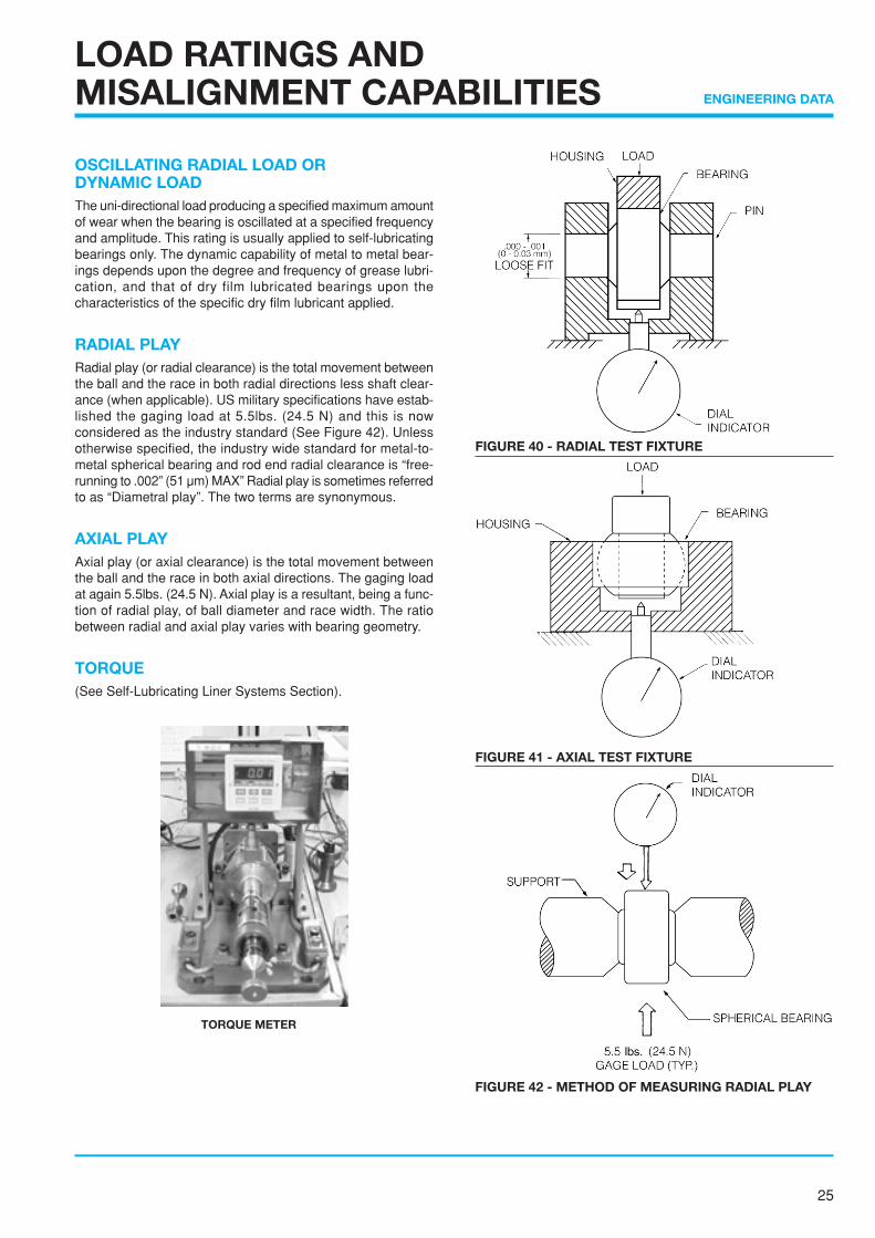
OSCILLATING RADIAL LOAD ORDYNAMIC LOADThe uni-directional load producing a specified maximum amountof wear when the bearing is oscillated at a specified frequencyand amplitude. This rating is usually applied to self-lubricatingbearings only. The dynamic capability of metal to metal bear-ings depends upon the degree and frequency of grease lubri-cation, and that of dry film lubricated bearings upon thecharacteristics of the specific dry film lubricant applied.
RADIAL PLAYRadial play (or radial clearance) is the total movement betweenthe ball and the race in both radial directions less shaft clear-ance (when applicable). US military specifications have estab-lished the gaging load at 5.5lbs. (24.5 N) and this is nowconsidered as the industry standard (See Figure 42). Unlessotherwise specified, the industry wide standard for metal-to-metal spherical bearing and rod end radial clearance is “free-running to .002” (51 µm) MAX” Radial play is sometimes referredto as “Diametral play”. The two terms are synonymous.
AXIAL PLAYAxial play (or axial clearance) is the total movement betweenthe ball and the race in both axial directions. The gaging loadat again 5.5lbs. (24.5 N). Axial play is a resultant, being a func-tion of radial play, of ball diameter and race width. The ratiobetween radial and axial play varies with bearing geometry.
TORQUE(See Self-Lubricating Liner Systems Section).
LOAD RATINGS ANDMISALIGNMENT CAPABILITIES
FIGURE 40 - RADIAL TEST FIXTURE
FIGURE 42 - METHOD OF MEASURING RADIAL PLAY
FIGURE 41 - AXIAL TEST FIXTURE
TORQUE METER
26
ENGINEERING DATA
LOAD RATINGS ANDMISALIGNMENT CAPABILITIES
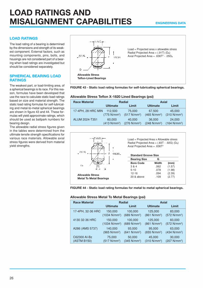
LOAD RATINGSThe load rating of a bearing is determinedby the dimensions and strength of its weak-est component. External factors, such asmounting components, pins, bolts, andhousings are not considered part of a bear-ing when load ratings are investigated butshould be considered separately.
SPHERICAL BEARING LOADRATINGSThe weakest part, or load-limiting area, ofa spherical bearings is its race. For this rea-son, formulas have been developed thatuse the race to calculate static load ratingsbased on size and material strength. Thestatic load rating formulas for self-lubricat-ing and metal-to-metal spherical bearingsare shown in figure 43 and 44. These for-mulas will yield approximate ratings, whichshould be used as ballpark numbers forbearing design.The allowable radial stress figures givenin the tables were determined from theultimate tensile strength specifications forvarious race materials. Allowable axialstress figures were derived from materialyield strengths.
Load = Projected area x allowable stressRadial Projected Area = (.91T) (DB)Axial Projected Area = .636T2 - .05DB
Allowable StressTeflon-Lined Bearings
FIGURE 43 - Static load rating formulas for self-lubricating spherical bearings.
Allowable StressMetal To Metal Bearings
Load = Projected Area x Allowable stressRadial Projected Area = (.83T - .92G) (DB)Axial Projected Area = .636T2
Standard Groove SizeBearing Size GBore Code Width (mm)3 & 4 .062 (1.57)5-10 .078 (1.98)12-16 .094 (2.39)20 & above .109 (2.77)
FIGURE 44 - Static load rating formulas for metal to metal spherical bearings.
Allowable Stress Teflon X-1820 Lined Bearings (psi)
Race Material Radial AxialUltimate Limit Ultimate Limit
17-4PH, 28 HRC MIN 112,500 75,000 67,500 45,000(775 N/mm2) (517 N/mm2) (465 N/mm2) (310 N/mm2)
ALUM 2024-T351 60,000 40,000 36,000 24,000(413 N/mm2) (276 N/mm2) (248 N/mm2) (164 N/mm2)
Allowable Stress Metal To Metal Bearings (psi)
Race Material Radial AxialUltimate Limit Ultimate Limit
17-4PH, 32-36 HRC 150,000 100,000 125,000 83,000(1034 N/mm2) (689 N/mm2) (861 N/mm2) (572 N/mm2)
4130 32-36 HRC 150,000 100,000 125,000 83,000(1034 N/mm2) (689 N/mm2) (861 N/mm2) (572 N/mm2)
A286 (AMS 5737) 140,000 93,000 95,000 63,000(965 N/mm2) (641 N/mm2) (655 N/mm2) (434 N/mm2)
C62300 AI-Bz 75,000 50,000 45,000 30,000(ASTM B150) (517 N/mm2) (345 N/mm2) (310 N/mm2) (207 N/mm2)
27
ENGINEERING DATA
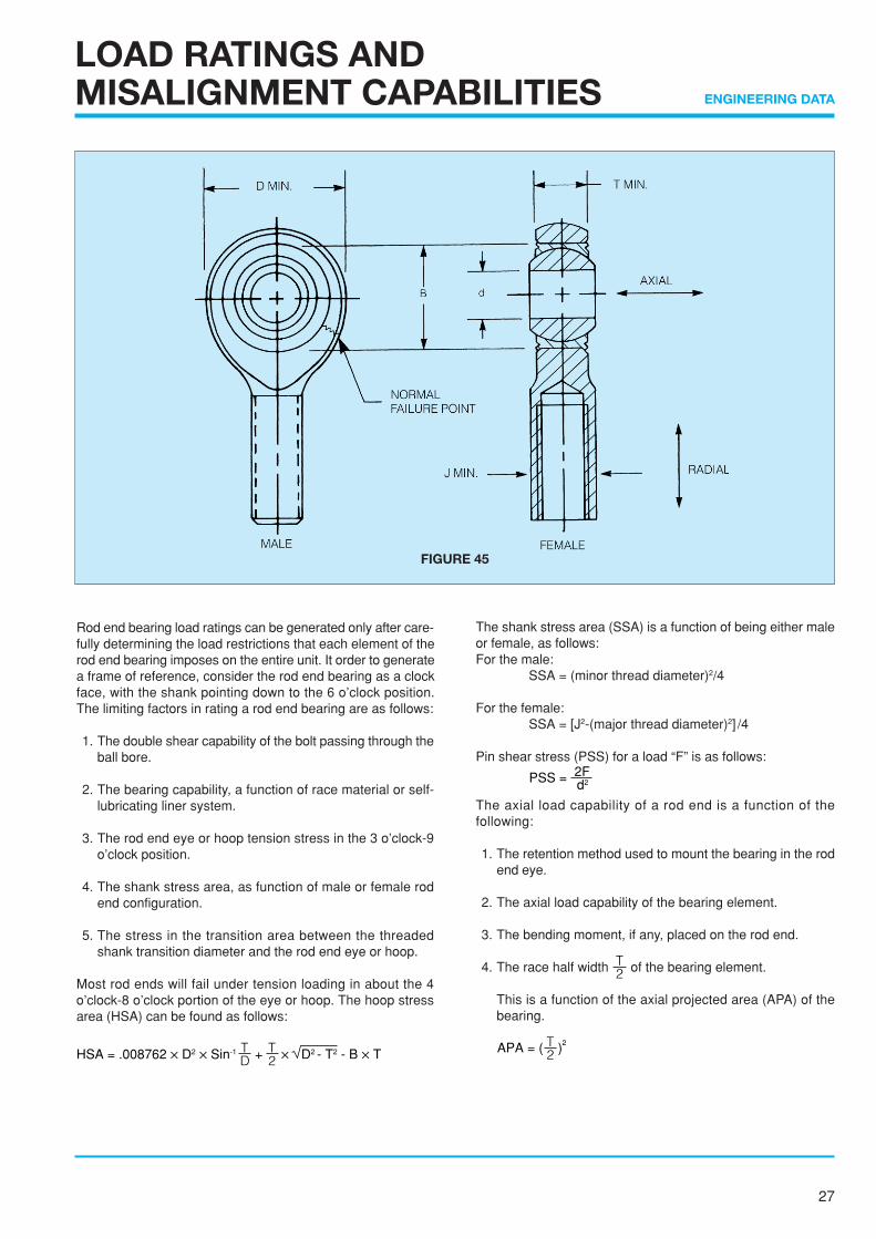
Rod end bearing load ratings can be generated only after care-fully determining the load restrictions that each element of therod end bearing imposes on the entire unit. It order to generatea frame of reference, consider the rod end bearing as a clockface, with the shank pointing down to the 6 o’clock position.The limiting factors in rating a rod end bearing are as follows:
1. The double shear capability of the bolt passing through theball bore.
2. The bearing capability, a function of race material or self-lubricating liner system.
3. The rod end eye or hoop tension stress in the 3 o’clock-9o’clock position.
4. The shank stress area, as function of male or female rodend configuration.
5. The stress in the transition area between the threadedshank transition diameter and the rod end eye or hoop.
Most rod ends will fail under tension loading in about the 4o’clock-8 o’clock portion of the eye or hoop. The hoop stressarea (HSA) can be found as follows:
HSA = .008762 ✕ D2 ✕ Sin-1 + ✕ D2 - T2 - B ✕ TTD
T2
LOAD RATINGS ANDMISALIGNMENT CAPABILITIES
The shank stress area (SSA) is a function of being either maleor female, as follows:For the male:
SSA = (minor thread diameter)2/4
For the female:SSA = [J2-(major thread diameter)2] /4
Pin shear stress (PSS) for a load “F” is as follows:
d2PSS = 2F
The axial load capability of a rod end is a function of thefollowing:
1. The retention method used to mount the bearing in the rodend eye.
2. The axial load capability of the bearing element.
3. The bending moment, if any, placed on the rod end.
4. The race half width T2 of the bearing element.
This is a function of the axial projected area (APA) of thebearing.
APA = ( )T2
2
FIGURE 45
28
ENGINEERING DATA
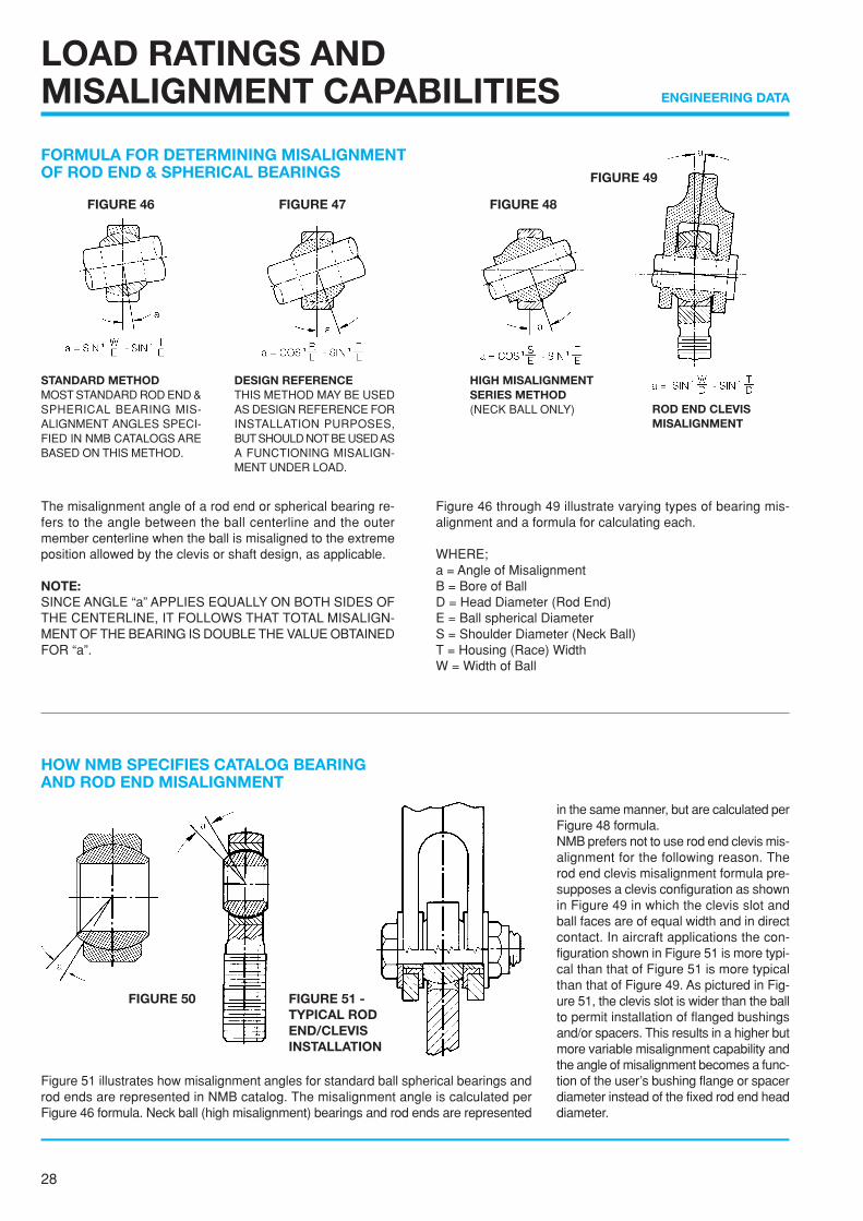
FORMULA FOR DETERMINING MISALIGNMENTOF ROD END & SPHERICAL BEARINGS
The misalignment angle of a rod end or spherical bearing re-fers to the angle between the ball centerline and the outermember centerline when the ball is misaligned to the extremeposition allowed by the clevis or shaft design, as applicable.
NOTE:SINCE ANGLE “a” APPLIES EQUALLY ON BOTH SIDES OFTHE CENTERLINE, IT FOLLOWS THAT TOTAL MISALIGN-MENT OF THE BEARING IS DOUBLE THE VALUE OBTAINEDFOR “a”.
LOAD RATINGS ANDMISALIGNMENT CAPABILITIES
Figure 46 through 49 illustrate varying types of bearing mis-alignment and a formula for calculating each.
WHERE;a = Angle of MisalignmentB = Bore of BallD = Head Diameter (Rod End)E = Ball spherical DiameterS = Shoulder Diameter (Neck Ball)T = Housing (Race) WidthW = Width of Ball
HOW NMB SPECIFIES CATALOG BEARINGAND ROD END MISALIGNMENT
STANDARD METHODMOST STANDARD ROD END &SPHERICAL BEARING MIS-ALIGNMENT ANGLES SPECI-FIED IN NMB CATALOGS AREBASED ON THIS METHOD.
DESIGN REFERENCETHIS METHOD MAY BE USEDAS DESIGN REFERENCE FORINSTALLATION PURPOSES,BUT SHOULD NOT BE USED ASA FUNCTIONING MISALIGN-MENT UNDER LOAD.
HIGH MISALIGNMENTSERIES METHOD(NECK BALL ONLY) ROD END CLEVIS
MISALIGNMENT
Figure 51 illustrates how misalignment angles for standard ball spherical bearings androd ends are represented in NMB catalog. The misalignment angle is calculated perFigure 46 formula. Neck ball (high misalignment) bearings and rod ends are represented
in the same manner, but are calculated perFigure 48 formula.NMB prefers not to use rod end clevis mis-alignment for the following reason. Therod end clevis misalignment formula pre-supposes a clevis configuration as shownin Figure 49 in which the clevis slot andball faces are of equal width and in directcontact. In aircraft applications the con-figuration shown in Figure 51 is more typi-cal than that of Figure 51 is more typicalthan that of Figure 49. As pictured in Fig-ure 51, the clevis slot is wider than the ballto permit installation of flanged bushingsand/or spacers. This results in a higher butmore variable misalignment capability andthe angle of misalignment becomes a func-tion of the user’s bushing flange or spacerdiameter instead of the fixed rod end headdiameter.
FIGURE 50 FIGURE 51 -TYPICAL RODEND/CLEVISINSTALLATION
FIGURE 46 FIGURE 47 FIGURE 48
FIGURE 49
29
ENGINEERING DATA
LOAD RATINGS ANDMISALIGNMENT CAPABILITIES
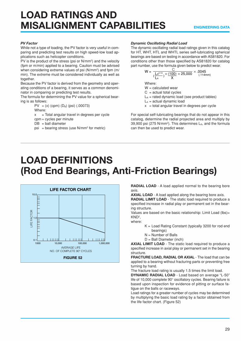
PV FactorWhile not a type of loading, the PV factor is very useful in com-paring and predicting test results on high speed-low load ap-plications such as helicopter conditions.PV is the product of the stress (psi or N/mm2) and the velocity(fpm or m/min) applied to a bearing. Caution must be advisedwhen considering extreme values of psi (N/mm2) and fpm (m/min). The extreme must be considered individually as well astogether.Because the PV factor is derived from the geometry and oper-ating conditions of a bearing, it serves as a common denomi-nator in comparing or predicting test results.The formula for determining the PV value for a spherical bear-ing is as follows:
PV = (x) (cpm) (DB) (psi) (.00073)Where:x = Total angular travel in degrees per cyclecpm = cycles per minuteDB = ball diameterpsi = bearing stress (use N/mm2 for metric)
Dynamic Oscillating Radial LoadThe dynamic oscillating radial load ratings given in this catalogfor HT, WHT, HTL and WHTL series self-lubricating sphericalbearings are based on testing in accordance with AS81820. Forconditions other than those specified by AS81820 for catalogpart number, use the formula given below to predict wear.
W = × .0045CLR
2.13
LA
× (100) × 25,000X
( ) (.114mm)
Where:W = calculated wearC = actual total cyclesLR = rated dynamic load (see product tables)LA = actual dynamic loadx = total angular travel in degrees per cycle
For special self-lubricating bearings that do not appear in thiscatalog, determine the radial projected area and multiply by39,900 psi (275 N/mm2). This determines LR, and the formulacan then be used to predict wear.
LOAD DEFINITIONS(Rod End Bearings, Anti-Friction Bearings)
RADIAL LOAD - A load applied normal to the bearing boreaxis.AXIAL LOAD - A load applied along the bearing bore axis.RADIAL LIMIT LOAD - The static load required to produce aspecified increase in radial play or permanent set in the bear-ing structure.Values are based on the basic relationship: Limit Load (lbs)=KND2,where:
K = Load Rating Constant (typically 3200 for rod endbearings)
N = Number of BallsD = Ball Diameter (inch)
AXIAL LIMIT LOAD - The static load required to produce aspecified increase in axial play or permanent set in the bearingstructure.FRACTURE LOAD, RADIAL OR AXIAL - The load that can beapplied to a bearing without fracturing parts or preventing freeturning by hand.The fracture load rating is usually 1.5 times the limit load.DYNAMIC RADIAL LOAD - Load based on average “L-50”life of 10,000 complete 90° oscillatory cycles. Bearing failure isbased upon inspection for evidence of pitting or surface fa-tigue on the balls or raceways.Load ratings for a greater number of cycles may be determinedby multiplying the basic load rating by a factor obtained fromthe life factor chart. (Figure 52)
FIGURE 52
LIFE FACTOR CHART10.0
1.0
0.11000 1,000,000100,00010,000
30
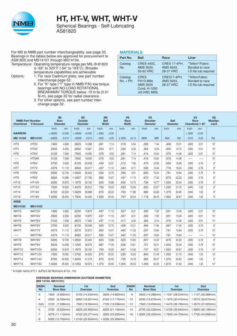
MATERIALSPart No. Ball Race Liner
Catalog CRES 440C, CRES 17-4PH, *Teflon®/FabricNo. AMS 5630, AMS 5643, Bonded to race
55-62 HRC 28-37 HRC I.D.No lub.required
Catalog CRES CRES17-4PH, *Teflon/FabricNo. + PH PH13-8Mo AMS 5643, Bonded to race
AMS 5629 28-37 HRC I.D.No lub.requiredCond. H-1000(43 HRC MIN)
For MS to NMB part number interchangeablity, see page 33.Bearings in the tables below are approved for procurement toAS81820 and MS14101 through MS14104.Temperature: Operating temperature range per MIL-B-81820
is -65° to 325°F (-54° to 163°C). Broadertemperature capabilities are achievable
Options: 1. For race Cadmium plate, see part numberinterchange page 32.
2. For “K” type (“T” type in NMB P/N) low torquebearings with NO-LOAD ROTATIONALBREAKAWAY TORQUE below .10 ln·lb (0.01N-m), see page 32 for radial clearance.
3. For other options, see part number inter-change page 32.
HT, HT-V, WHT, WHT-VSpherical Bearings - Self-LubricatingAS81820
(B) (D) (W) (H) (O) (C) (Q)NMB Part Number Bore Outside Ball Race Shoulder Ball Race Misalign-
Chamfered V-Grooved Diameter Diameter Width Width Diameter Diameter Chamfered ✕ 45° ment
Inch mm Inch mm Inch mm Inch mm Inch mm Inch mm Inch mm
NARROW +.0000 +0.000 +.0000 +0.000 +.000 +0.00 +.000 +0.00
MS 14104 MS14101 -.0005 -0.013 -.0005 -0.013 -.002 -0.05 ±.005 ±0.13 MIN MIN Ref. Ref. -.010 -0.25 Ref.
HT3 HT3V .1900 4.826 .5625 14.288 .281 7.14 .218 5.54 .293 7.44 .406 10.31 .020 0.51 10°
HT4 HT4V .2500 6.350 .6562 16.667 .343 8.71 .250 6.35 .364 9.25 .500 12.70 .020 0.51 10°
HT5 HT5V .3125 7.938 .7500 19.050 .375 9.52 .281 7.14 .419 10.64 .570 14.48 .020 0.51 10°
–— HT5AV .3125 7.938 .7500 19.050 .375 9.52 .281 7.14 .419 10.64 .570 14.48 –— –— 10°
HT6 HT6V .3750 9.525 .8125 20.638 .406 10.31 .312 7.92 .475 12.06 .656 16.66 .030 0.76 9°
HT7 HT7V .4375 11.112 .9062 23.017 .437 11.10 .343 8.71 .530 13.46 .718 18.24 .030 0.76 8°
HT8 HT8V .5000 12.700 1.0000 25.400 .500 12.70 .390 9.91 .600 15.24 .781 19.84 .030 0.76 8°
HT9 HT9V .5625 14.288 1.0937 27.780 .562 14.27 .437 11.10 .670 17.02 .875 22.22 .030 0.76 8°
HT10 HT10V .6250 15.875 1.1875 30.162 .625 15.88 .500 12.70 .739 18.77 1.000 25.40 .030 0.76 8°
HT12 HT12V .7500 19.050 1.4375 36.512 .750 19.05 .593 15.06 .920 23.37 1.250 31.75 .040 1.02 8°
HT14 HT14V .8750 22.225 1.5625 39.688 .875 22.22 .703 17.86 .980 24.89 1.375 34.92 .040 1.02 8°
HT16 HT16V 1.0000 25.400 1.7500 44.450 1.000 25.40 .797 20.24 1.118 28.40 1.562 39.67 .040 1.02 9°
WIDE
MS14102 MS14103
WHT3 WHT3V .1900 4.826 .6250 15.875 .437 11.10 .327 8.31 .300 7.62 .531 13.49 .020 0.51 15°
WHT4 WHT4V .2500 6.350 .6250 15.875 .437 11.10 .327 8.31 .300 7.62 .531 13.49 .020 0.51 15°
WHT5 WHT5V .3125 7.938 .6875 17.462 .437 11.10 .317 8.05 .360 9.14 .570 14.48 .020 0.51 14°
WHT6 WHT6V .3750 9.525 .8125 20.638 .500 12.70 .406 10.31 .466 11.84 .687 17.45 .030 0.76 8°
WHT7 WHT7V .4375 11.112 .9375 23.812 .562 14.27 .442 11.23 .537 13.64 .781 19.84 .030 0.76 10°
–— WHT7AV .4375 11.112 .9062 23.017 .562 14.27 .442 11.23 .537 13.64 .781 19.84 –— –— 10°
WHT8 WHT8V .5000 12.700 1.0000 25.400 .625 15.88 .505 12.83 .607 15.42 .875 22.22 .030 0.76 9°
WHT9 WHT9V .5625 14.288 1.1250 28.575 .687 17.45 .536 13.61 .721 18.31 1.000 25.40 .030 0.76 10°
WHT10 WHT10V .6250 15.875 1.1875 30.162 .750 19.05 .567 14.40 .747 18.97 1.062 26.97 .030 0.76 12°
WHT12 WHT12V .7500 19.050 1.3750 34.925 .875 22.22 .630 16.00 .845 21.46 1.250 31.75 .040 1.02 13°
WHT14 WHT14V .8750 22.225 1.6250 41.275 .875 22.22 .755 19.18 .995 25.27 1.375 34.92 .040 1.02 6°
WHT16 WHT16V 1.0000 25.400 2.1250 53.975 1.375 34.92 1.005 25.53 1.269 32.23 1.875 47.62 .040 1.02 12°
* A trade name of E.I. duPont de Nemours & Co., Inc.
OVERSIZE BEARING DIMENSION (OUTSIDE DIAMETER)(MS 14104. MS14101)
DASH Nominal 1st 2ndNo Bore Size Oversize Oversize
-3 .1900 (4.826mm) .5725 (14.542mm) .5825 (14.800mm)
-4 .2500 (6.350mm) .6662 (16.921mm) .6762 (17.175mm)
-5(A) .3125 (7.938mm) .7600 (19.304mm) .7700 (19.558mm)
-6 .3750 (9.525mm) .8225 (20.892mm) .8325 (21.146mm)
-7 .4375 (11.112mm) .9162 (23.271mm) .9262 (23.525mm)
-8 .5000 (12.700mm) 1.0100 (25.654mm) 1.0200 (25.908mm)
DASH Nominal 1st 2ndNo Bore Size Oversize Oversize
-9 .5625 (14.288mm) 1.1037 (28.034mm) 1.1137 (28.288mm)
-10 .6250 (15.875mm) 1.1975 (30.416mm) 1.2075 (30.670mm)
-12 .7500 (19.050mm) 1.4475 (36.766mm) 1.4575 (37.020mm)
-14 .8750 (22.225mm) 1.5725 (39.942mm) 1.5825 (40.196mm)
-16 1.0000 (25.400mm) 1.7600 (44.704mm) 1.7700 (44.958mm)
31
H W
B
- B -
R
V-GROOVE TYPE
-3 TRU-5 -6 TRU-8 -9 TRU-10 -12 TRU-16
.030 MAX. .035 MAX. .040 MAX. .045 MAX.
CHAMFER TYPE
P
T°
E
30°
DBO
Q
C LINER
SET BACK
BØ.005(Ø 0.13mm)
.005 (0.13mm)
.015 (0.38mm)45°CHAMFER
STAKING GROOVE
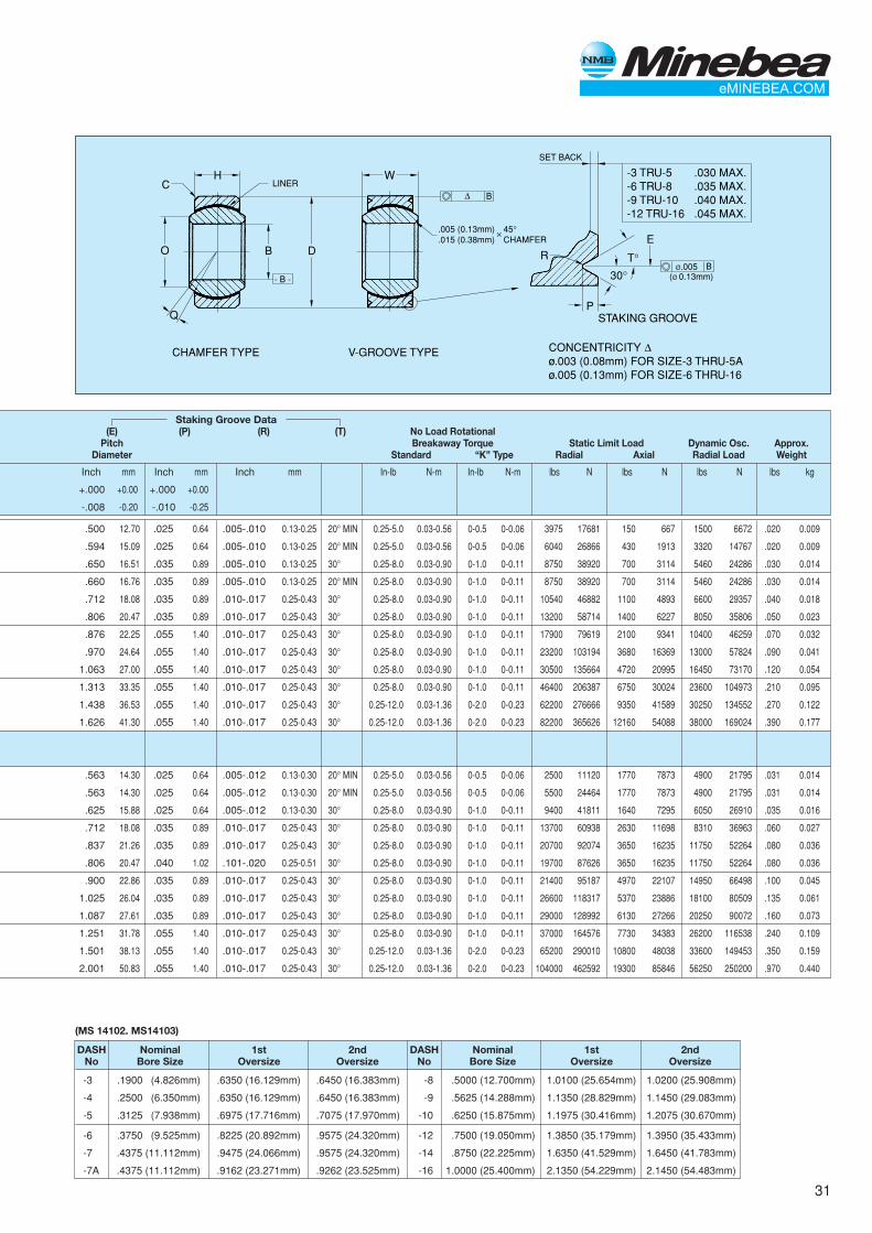
CONCENTRICITY ø.003 (0.08mm) FOR SIZE-3 THRU-5Aø.005 (0.13mm) FOR SIZE-6 THRU-16
✕
Staking Groove Data(E) (P) (R) (T) No Load Rotational
Pitch Breakaway Torque Static Limit Load Dynamic Osc. Approx.Diameter Standard “K” Type Radial Axial Radial Load Weight
Inch mm Inch mm Inch mm In-lb N-m In-lb N-m lbs N lbs N lbs N lbs kg
+.000 +0.00 +.000 +0.00
-.008 -0.20 -.010 -0.25
.500 12.70 .025 0.64 .005-.010 0.13-0.25 20° MIN 0.25-5.0 0.03-0.56 0-0.5 0-0.06 3975 17681 150 667 1500 6672 .020 0.009
.594 15.09 .025 0.64 .005-.010 0.13-0.25 20° MIN 0.25-5.0 0.03-0.56 0-0.5 0-0.06 6040 26866 430 1913 3320 14767 .020 0.009
.650 16.51 .035 0.89 .005-.010 0.13-0.25 30° 0.25-8.0 0.03-0.90 0-1.0 0-0.11 8750 38920 700 3114 5460 24286 .030 0.014
.660 16.76 .035 0.89 .005-.010 0.13-0.25 20° MIN 0.25-8.0 0.03-0.90 0-1.0 0-0.11 8750 38920 700 3114 5460 24286 .030 0.014
.712 18.08 .035 0.89 .010-.017 0.25-0.43 30° 0.25-8.0 0.03-0.90 0-1.0 0-0.11 10540 46882 1100 4893 6600 29357 .040 0.018
.806 20.47 .035 0.89 .010-.017 0.25-0.43 30° 0.25-8.0 0.03-0.90 0-1.0 0-0.11 13200 58714 1400 6227 8050 35806 .050 0.023
.876 22.25 .055 1.40 .010-.017 0.25-0.43 30° 0.25-8.0 0.03-0.90 0-1.0 0-0.11 17900 79619 2100 9341 10400 46259 .070 0.032
.970 24.64 .055 1.40 .010-.017 0.25-0.43 30° 0.25-8.0 0.03-0.90 0-1.0 0-0.11 23200 103194 3680 16369 13000 57824 .090 0.041
1.063 27.00 .055 1.40 .010-.017 0.25-0.43 30° 0.25-8.0 0.03-0.90 0-1.0 0-0.11 30500 135664 4720 20995 16450 73170 .120 0.054
1.313 33.35 .055 1.40 .010-.017 0.25-0.43 30° 0.25-8.0 0.03-0.90 0-1.0 0-0.11 46400 206387 6750 30024 23600 104973 .210 0.095
1.438 36.53 .055 1.40 .010-.017 0.25-0.43 30° 0.25-12.0 0.03-1.36 0-2.0 0-0.23 62200 276666 9350 41589 30250 134552 .270 0.122
1.626 41.30 .055 1.40 .010-.017 0.25-0.43 30° 0.25-12.0 0.03-1.36 0-2.0 0-0.23 82200 365626 12160 54088 38000 169024 .390 0.177
.563 14.30 .025 0.64 .005-.012 0.13-0.30 20° MIN 0.25-5.0 0.03-0.56 0-0.5 0-0.06 2500 11120 1770 7873 4900 21795 .031 0.014
.563 14.30 .025 0.64 .005-.012 0.13-0.30 20° MIN 0.25-5.0 0.03-0.56 0-0.5 0-0.06 5500 24464 1770 7873 4900 21795 .031 0.014
.625 15.88 .025 0.64 .005-.012 0.13-0.30 30° 0.25-8.0 0.03-0.90 0-1.0 0-0.11 9400 41811 1640 7295 6050 26910 .035 0.016
.712 18.08 .035 0.89 .010-.017 0.25-0.43 30° 0.25-8.0 0.03-0.90 0-1.0 0-0.11 13700 60938 2630 11698 8310 36963 .060 0.027
.837 21.26 .035 0.89 .010-.017 0.25-0.43 30° 0.25-8.0 0.03-0.90 0-1.0 0-0.11 20700 92074 3650 16235 11750 52264 .080 0.036
.806 20.47 .040 1.02 .101-.020 0.25-0.51 30° 0.25-8.0 0.03-0.90 0-1.0 0-0.11 19700 87626 3650 16235 11750 52264 .080 0.036
.900 22.86 .035 0.89 .010-.017 0.25-0.43 30° 0.25-8.0 0.03-0.90 0-1.0 0-0.11 21400 95187 4970 22107 14950 66498 .100 0.045
1.025 26.04 .035 0.89 .010-.017 0.25-0.43 30° 0.25-8.0 0.03-0.90 0-1.0 0-0.11 26600 118317 5370 23886 18100 80509 .135 0.061
1.087 27.61 .035 0.89 .010-.017 0.25-0.43 30° 0.25-8.0 0.03-0.90 0-1.0 0-0.11 29000 128992 6130 27266 20250 90072 .160 0.073
1.251 31.78 .055 1.40 .010-.017 0.25-0.43 30° 0.25-8.0 0.03-0.90 0-1.0 0-0.11 37000 164576 7730 34383 26200 116538 .240 0.109
1.501 38.13 .055 1.40 .010-.017 0.25-0.43 30° 0.25-12.0 0.03-1.36 0-2.0 0-0.23 65200 290010 10800 48038 33600 149453 .350 0.159
2.001 50.83 .055 1.40 .010-.017 0.25-0.43 30° 0.25-12.0 0.03-1.36 0-2.0 0-0.23 104000 462592 19300 85846 56250 250200 .970 0.440
DASH Nominal 1st 2ndNo Bore Size Oversize Oversize
-8 .5000 (12.700mm) 1.0100 (25.654mm) 1.0200 (25.908mm)
-9 .5625 (14.288mm) 1.1350 (28.829mm) 1.1450 (29.083mm)
-10 .6250 (15.875mm) 1.1975 (30.416mm) 1.2075 (30.670mm)
-12 .7500 (19.050mm) 1.3850 (35.179mm) 1.3950 (35.433mm)
-14 .8750 (22.225mm) 1.6350 (41.529mm) 1.6450 (41.783mm)
-16 1.0000 (25.400mm) 2.1350 (54.229mm) 2.1450 (54.483mm)
(MS 14102. MS14103)
DASH Nominal 1st 2ndNo Bore Size Oversize Oversize
-3 .1900 (4.826mm) .6350 (16.129mm) .6450 (16.383mm)
-4 .2500 (6.350mm) .6350 (16.129mm) .6450 (16.383mm)
-5 .3125 (7.938mm) .6975 (17.716mm) .7075 (17.970mm)
-6 .3750 (9.525mm) .8225 (20.892mm) .9575 (24.320mm)
-7 .4375 (11.112mm) .9475 (24.066mm) .9575 (24.320mm)
-7A .4375 (11.112mm) .9162 (23.271mm) .9262 (23.525mm)
32
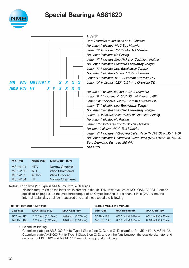
Notes: 1. “K” Type (“T” Type in NMB) Low Torque BearingsNo load torque: When the letter “K” is present in the MS P/N, lower values of NO LOAD TORQUE are asspecified on page 31. If the measured torque of a “K” type bearing is less than .1 ln·lb (0.01 N-m), theinternal radial play shall be measured and shall not exceed the following:
2. Cadmium PlatingCadmium plate per AMS-QQ-P-416 Type II Class 2 on O. D. and O. D. chamfers for MS14101 & MS14103.Cadmium plate AMS-QQ-P-416 Type II Class 2 on O. D. and on the flats between the outside diameter andgrooves for MS14102 and MS14104 Dimensions apply after plating.
Special Bearings AS81820
MS P/NBore Diameter in Multiples of 1/16 inchesNo Letter Indicates 440C Ball MaterialLetter “C” Indicates PH13-8Mo Ball MaterialNo Letter Indicates No PlatingLetter “P” Indicates Zinc-Nickel or Cadmium PlatingNo Letter Indicates Standard Breakaway TorqueLetter “K” Indicates Low Breakaway TorqueNo Letter Indicates standard Outer DiameterLetter “T” Indicates .010” (0.25mm) Oversize ØDLetter “U” Indicates .020” (0.51mm) Oversize ØD
No Letter Indicates standard Outer DiameterLetter “R1” Indicates .010” (0.25mm) Oversize ØDLetter “R2” Indicates .020” (0.51mm) Oversize ØDLetter “T” Indicates Low Breakaway TorqueNo Letter Indicates Standard Breakaway TorqueLetter “D” Indicates Zinc-Nickel or Cadmium PlatingNo Letter Indicates No PlatingLetter “PH” Indicates PH13-8Mo Ball MaterialNo letter Indicates 440C Ball MaterialLetter “V” Indicates V-Grooved Outer Race (MS14101 & MS14103)No Letter Indicates Chamfered Outer Race (MS14102 & MS14104)Bore Diameter: Same as MS P/NNMB P/N
MS P/N MS14101-X X X X XNMB P/N HT X V X X X X
SERIES MS14102 & MS14103
Bore Size MAX Radial Play MAX Axial Play
3K Thru 12K .0007 Inch (0.018mm) .0021 Inch (0.053mm)
14K Thru 16K .0010 Inch (0.025mm) .0030 Inch (0.076mm)
SERIES MS14101 & MS14104
Bore Size MAX Radial Play MAX Axial Play
3K Thru 12K .0007 Inch (0.018mm) .0028 Inch (0.071mm)
14K Thru 16K .0010 Inch (0.025mm) .0040 Inch (0.102mm)
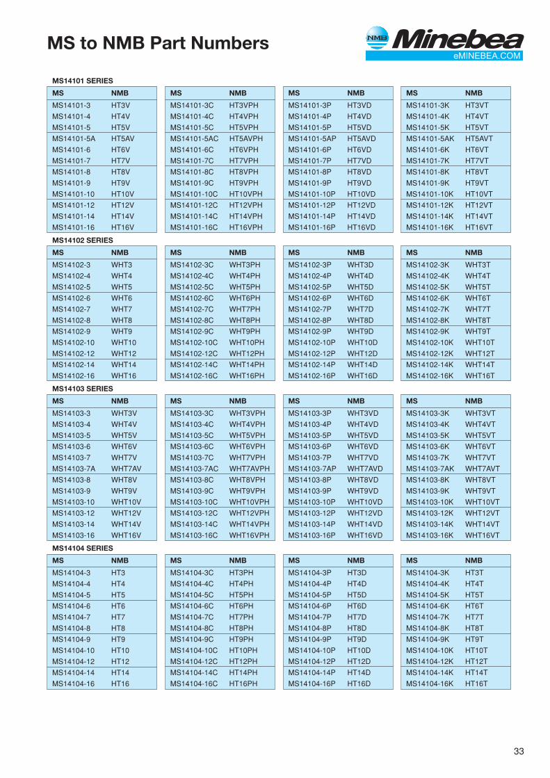
MS P/N NMB P/N DESCRIPTION
MS 14101 HT-V Narrow GroovedMS 14102 WHT Wide ChamferedMS 14103 WHT-V Wide GroovedMS 14104 HT Narrow Chamfered
33
MS to NMB Part Numbers
MS14103 SERIES
MS NMB
MS14103-3 WHT3V
MS14103-4 WHT4V
MS14103-5 WHT5V
MS14103-6 WHT6V
MS14103-7 WHT7V
MS14103-7A WHT7AV
MS14103-8 WHT8V
MS14103-9 WHT9V
MS14103-10 WHT10V
MS14103-12 WHT12V
MS14103-14 WHT14V
MS14103-16 WHT16V
MS14102 SERIES
MS NMB
MS14102-3 WHT3
MS14102-4 WHT4
MS14102-5 WHT5
MS14102-6 WHT6
MS14102-7 WHT7
MS14102-8 WHT8
MS14102-9 WHT9
MS14102-10 WHT10
MS14102-12 WHT12
MS14102-14 WHT14
MS14102-16 WHT16
MS14101 SERIES
MS NMB
MS14101-3 HT3V
MS14101-4 HT4V
MS14101-5 HT5V
MS14101-5A HT5AV
MS14101-6 HT6V
MS14101-7 HT7V
MS14101-8 HT8V
MS14101-9 HT9V
MS14101-10 HT10V
MS14101-12 HT12V
MS14101-14 HT14V
MS14101-16 HT16V
MS NMB
MS14101-3C HT3VPH
MS14101-4C HT4VPH
MS14101-5C HT5VPH
MS14101-5AC HT5AVPH
MS14101-6C HT6VPH
MS14101-7C HT7VPH
MS14101-8C HT8VPH
MS14101-9C HT9VPH
MS14101-10C HT10VPH
MS14101-12C HT12VPH
MS14101-14C HT14VPH
MS14101-16C HT16VPH
MS NMB
MS14101-3P HT3VD
MS14101-4P HT4VD
MS14101-5P HT5VD
MS14101-5AP HT5AVD
MS14101-6P HT6VD
MS14101-7P HT7VD
MS14101-8P HT8VD
MS14101-9P HT9VD
MS14101-10P HT10VD
MS14101-12P HT12VD
MS14101-14P HT14VD
MS14101-16P HT16VD
MS NMB
MS14101-3K HT3VT
MS14101-4K HT4VT
MS14101-5K HT5VT
MS14101-5AK HT5AVT
MS14101-6K HT6VT
MS14101-7K HT7VT
MS14101-8K HT8VT
MS14101-9K HT9VT
MS14101-10K HT10VT
MS14101-12K HT12VT
MS14101-14K HT14VT
MS14101-16K HT16VT
MS NMB
MS14102-3C WHT3PH
MS14102-4C WHT4PH
MS14102-5C WHT5PH
MS14102-6C WHT6PH
MS14102-7C WHT7PH
MS14102-8C WHT8PH
MS14102-9C WHT9PH
MS14102-10C WHT10PH
MS14102-12C WHT12PH
MS14102-14C WHT14PH
MS14102-16C WHT16PH
MS NMB
MS14102-3P WHT3D
MS14102-4P WHT4D
MS14102-5P WHT5D
MS14102-6P WHT6D
MS14102-7P WHT7D
MS14102-8P WHT8D
MS14102-9P WHT9D
MS14102-10P WHT10D
MS14102-12P WHT12D
MS14102-14P WHT14D
MS14102-16P WHT16D
MS NMB
MS14102-3K WHT3T
MS14102-4K WHT4T
MS14102-5K WHT5T
MS14102-6K WHT6T
MS14102-7K WHT7T
MS14102-8K WHT8T
MS14102-9K WHT9T
MS14102-10K WHT10T
MS14102-12K WHT12T
MS14102-14K WHT14T
MS14102-16K WHT16T
MS NMB
MS14103-3C WHT3VPH
MS14103-4C WHT4VPH
MS14103-5C WHT5VPH
MS14103-6C WHT6VPH
MS14103-7C WHT7VPH
MS14103-7AC WHT7AVPH
MS14103-8C WHT8VPH
MS14103-9C WHT9VPH
MS14103-10C WHT10VPH
MS14103-12C WHT12VPH
MS14103-14C WHT14VPH
MS14103-16C WHT16VPH
MS NMB
MS14103-3P WHT3VD
MS14103-4P WHT4VD
MS14103-5P WHT5VD
MS14103-6P WHT6VD
MS14103-7P WHT7VD
MS14103-7AP WHT7AVD
MS14103-8P WHT8VD
MS14103-9P WHT9VD
MS14103-10P WHT10VD
MS14103-12P WHT12VD
MS14103-14P WHT14VD
MS14103-16P WHT16VD
MS NMB
MS14103-3K WHT3VT
MS14103-4K WHT4VT
MS14103-5K WHT5VT
MS14103-6K WHT6VT
MS14103-7K WHT7VT
MS14103-7AK WHT7AVT
MS14103-8K WHT8VT
MS14103-9K WHT9VT
MS14103-10K WHT10VT
MS14103-12K WHT12VT
MS14103-14K WHT14VT
MS14103-16K WHT16VT
MS NMB
MS14104-3K HT3T
MS14104-4K HT4T
MS14104-5K HT5T
MS14104-6K HT6T
MS14104-7K HT7T
MS14104-8K HT8T
MS14104-9K HT9T
MS14104-10K HT10T
MS14104-12K HT12T
MS14104-14K HT14T
MS14104-16K HT16T
MS14104 SERIES
MS NMB
MS14104-3 HT3
MS14104-4 HT4
MS14104-5 HT5
MS14104-6 HT6
MS14104-7 HT7
MS14104-8 HT8
MS14104-9 HT9
MS14104-10 HT10
MS14104-12 HT12
MS14104-14 HT14
MS14104-16 HT16
MS NMB
MS14104-3C HT3PH
MS14104-4C HT4PH
MS14104-5C HT5PH
MS14104-6C HT6PH
MS14104-7C HT7PH
MS14104-8C HT8PH
MS14104-9C HT9PH
MS14104-10C HT10PH
MS14104-12C HT12PH
MS14104-14C HT14PH
MS14104-16C HT16PH
MS NMB
MS14104-3P HT3D
MS14104-4P HT4D
MS14104-5P HT5D
MS14104-6P HT6D
MS14104-7P HT7D
MS14104-8P HT8D
MS14104-9P HT9D
MS14104-10P HT10D
MS14104-12P HT12D
MS14104-14P HT14D
MS14104-16P HT16D
34
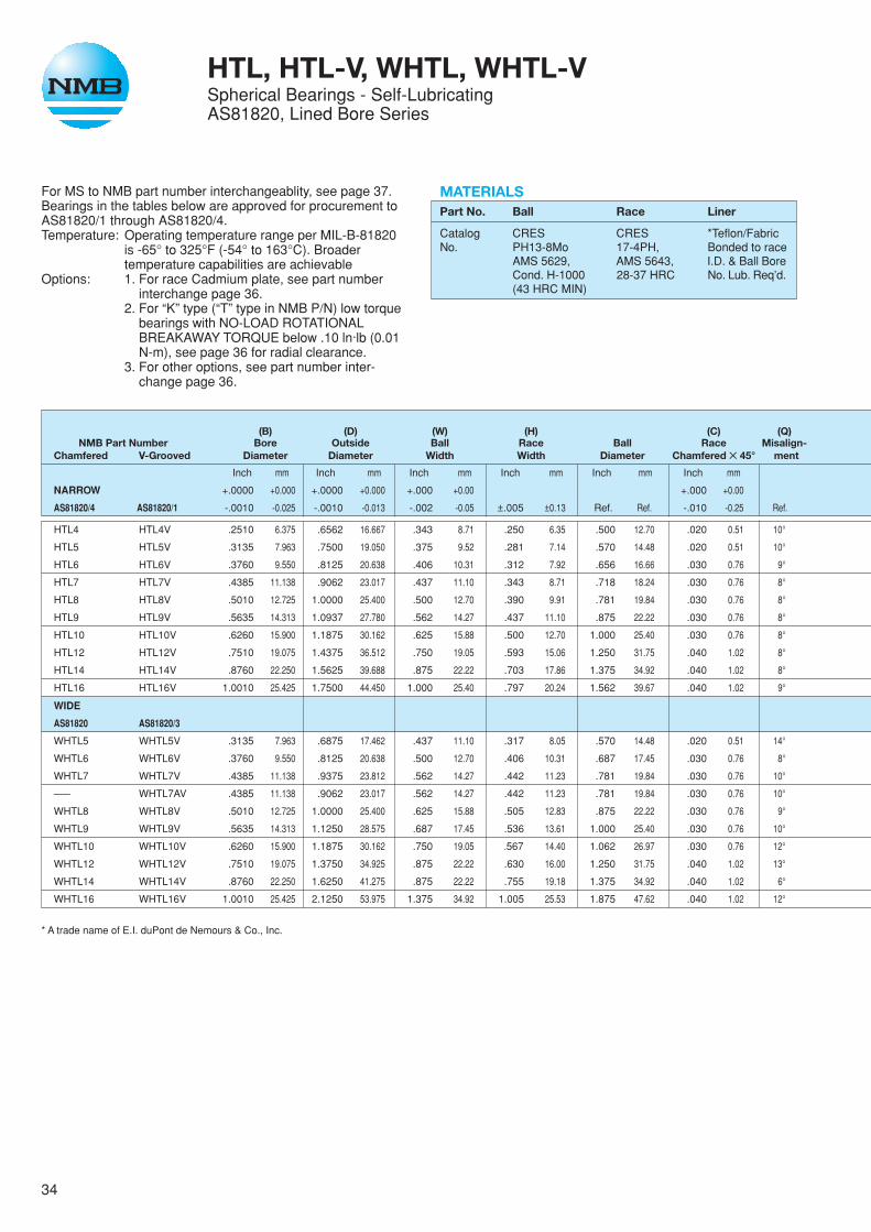
For MS to NMB part number interchangeablity, see page 37.Bearings in the tables below are approved for procurement toAS81820/1 through AS81820/4.Temperature: Operating temperature range per MIL-B-81820
is -65° to 325°F (-54° to 163°C). Broadertemperature capabilities are achievable
Options: 1. For race Cadmium plate, see part numberinterchange page 36.
2. For “K” type (“T” type in NMB P/N) low torquebearings with NO-LOAD ROTATIONALBREAKAWAY TORQUE below .10 ln·lb (0.01N-m), see page 36 for radial clearance.
3. For other options, see part number inter-change page 36.
HTL, HTL-V, WHTL, WHTL-VSpherical Bearings - Self-LubricatingAS81820, Lined Bore Series
MATERIALSPart No. Ball Race Liner
Catalog CRES CRES *Teflon/FabricNo. PH13-8Mo 17-4PH, Bonded to race
AMS 5629, AMS 5643, I.D. & Ball BoreCond. H-1000 28-37 HRC No. Lub. Req’d.(43 HRC MIN)
(B) (D) (W) (H) (C) (Q)NMB Part Number Bore Outside Ball Race Ball Race Misalign-
Chamfered V-Grooved Diameter Diameter Width Width Diameter Chamfered ✕ 45° ment
Inch mm Inch mm Inch mm Inch mm Inch mm Inch mm
NARROW +.0000 +0.000 +.0000 +0.000 +.000 +0.00 +.000 +0.00
AS81820/4 AS81820/1 -.0010 -0.025 -.0010 -0.013 -.002 -0.05 ±.005 ±0.13 Ref. Ref. -.010 -0.25 Ref.
HTL4 HTL4V .2510 6.375 .6562 16.667 .343 8.71 .250 6.35 .500 12.70 .020 0.51 10°
HTL5 HTL5V .3135 7.963 .7500 19.050 .375 9.52 .281 7.14 .570 14.48 .020 0.51 10°
HTL6 HTL6V .3760 9.550 .8125 20.638 .406 10.31 .312 7.92 .656 16.66 .030 0.76 9°
HTL7 HTL7V .4385 11.138 .9062 23.017 .437 11.10 .343 8.71 .718 18.24 .030 0.76 8°
HTL8 HTL8V .5010 12.725 1.0000 25.400 .500 12.70 .390 9.91 .781 19.84 .030 0.76 8°
HTL9 HTL9V .5635 14.313 1.0937 27.780 .562 14.27 .437 11.10 .875 22.22 .030 0.76 8°
HTL10 HTL10V .6260 15.900 1.1875 30.162 .625 15.88 .500 12.70 1.000 25.40 .030 0.76 8°
HTL12 HTL12V .7510 19.075 1.4375 36.512 .750 19.05 .593 15.06 1.250 31.75 .040 1.02 8°
HTL14 HTL14V .8760 22.250 1.5625 39.688 .875 22.22 .703 17.86 1.375 34.92 .040 1.02 8°
HTL16 HTL16V 1.0010 25.425 1.7500 44.450 1.000 25.40 .797 20.24 1.562 39.67 .040 1.02 9°
WIDE
AS81820 AS81820/3
WHTL5 WHTL5V .3135 7.963 .6875 17.462 .437 11.10 .317 8.05 .570 14.48 .020 0.51 14°
WHTL6 WHTL6V .3760 9.550 .8125 20.638 .500 12.70 .406 10.31 .687 17.45 .030 0.76 8°
WHTL7 WHTL7V .4385 11.138 .9375 23.812 .562 14.27 .442 11.23 .781 19.84 .030 0.76 10°
—— WHTL7AV .4385 11.138 .9062 23.017 .562 14.27 .442 11.23 .781 19.84 .030 0.76 10°
WHTL8 WHTL8V .5010 12.725 1.0000 25.400 .625 15.88 .505 12.83 .875 22.22 .030 0.76 9°
WHTL9 WHTL9V .5635 14.313 1.1250 28.575 .687 17.45 .536 13.61 1.000 25.40 .030 0.76 10°
WHTL10 WHTL10V .6260 15.900 1.1875 30.162 .750 19.05 .567 14.40 1.062 26.97 .030 0.76 12°
WHTL12 WHTL12V .7510 19.075 1.3750 34.925 .875 22.22 .630 16.00 1.250 31.75 .040 1.02 13°
WHTL14 WHTL14V .8760 22.250 1.6250 41.275 .875 22.22 .755 19.18 1.375 34.92 .040 1.02 6°
WHTL16 WHTL16V 1.0010 25.425 2.1250 53.975 1.375 34.92 1.005 25.53 1.875 47.62 .040 1.02 12°
* A trade name of E.I. duPont de Nemours & Co., Inc.
35
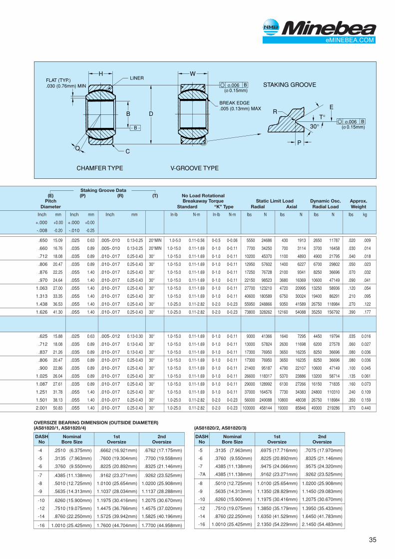
H W
- B -
R
V-GROOVE TYPE
STAKING GROOVE
CHAMFER TYPE
P
T°
E
30°
DB
Q C
LINERFLAT (TYP.).030 (0.76mm) MIN
BØ.006(Ø 0.15mm)
BØ.006(Ø 0.15mm)
BREAK EDGE.005 (0.13mm) MAX
OVERSIZE BEARING DIMENSION (OUTSIDE DIAMETER)(AS81820/1, AS81820/4)
DASH Nominal 1st 2ndNo Bore Size Oversize Oversize
-4 .2510 (6.375mm) .6662 (16.921mm) .6762 (17.175mm)
-5 .3135 (7.963mm) .7600 (19.304mm) .7700 (19.558mm)
-6 .3760 (9.550mm) .8225 (20.892mm) .8325 (21.146mm)
-7 .4385 (11.138mm) .9162 (23.271mm) .9262 (23.525mm)
-8 .5010 (12.725mm) 1.0100 (25.654mm) 1.0200 (25.908mm)
-9 .5635 (14.313mm) 1.1037 (28.034mm) 1.1137 (28.288mm)
-10 .6260 (15.900mm) 1.1975 (30.416mm) 1.2075 (30.670mm)
-12 .7510 (19.075mm) 1.4475 (36.766mm) 1.4575 (37.020mm)
-14 .8760 (22.250mm) 1.5725 (39.942mm) 1.5825 (40.196mm)
-16 1.0010 (25.425mm) 1.7600 (44.704mm) 1.7700 (44.958mm)
(AS81820/2, AS81820/3)
DASH Nominal 1st 2ndNo Bore Size Oversize Oversize
-5 .3135 (7.963mm) .6975 (17.716mm) .7075 (17.970mm)
-6 .3760 (9.550mm) .8225 (20.892mm) .8325 (21.146mm)
-7 .4385 (11.138mm) .9475 (24.066mm) .9575 (24.320mm)
-7A .4385 (11.138mm) .9162 (23.271mm) .9262 (23.525mm)
-8 .5010 (12.725mm) 1.0100 (25.654mm) 1.0200 (25.908mm)
-9 .5635 (14.313mm) 1.1350 (28.829mm) 1.1450 (29.083mm)
-10 .6260 (15.900mm) 1.1975 (30.416mm) 1.2075 (30.670mm)
-12 .7510 (19.075mm) 1.3850 (35.179mm) 1.3950 (35.433mm)
-14 .8760 (22.250mm) 1.6350 (41.529mm) 1.6450 (41.783mm)
-16 1.0010 (25.425mm) 2.1350 (54.229mm) 2.1450 (54.483mm)
Staking Groove Data(E) (P) (R) (T) No Load Rotational
Pitch Breakaway Torque Static Limit Load Dynamic Osc. Approx.Diameter Standard “K” Type Radial Axial Radial Load Weight
Inch mm Inch mm Inch mm In-lb N-m In-lb N-m lbs N lbs N lbs N lbs kg
+.000 +0.00 +.000 +0.00
-.008 -0.20 -.010 -0.25
.650 15.09 .025 0.63 .005-.010 0.13-0.25 20°MIN 1.0-5.0 0.11-0.56 0-0.5 0-0.06 5550 24686 430 1913 2650 11787 .020 .009
.660 16.76 .035 0.89 .005-.010 0.13-0.25 20°MIN 1.0-15.0 0.11-1.69 0-1.0 0-0.11 7700 34250 700 3114 3700 16458 .030 .014
.712 18.08 .035 0.89 .010-.017 0.25-0.43 30° 1.0-15.0 0.11-1.69 0-1.0 0-0.11 10200 45370 1100 4893 4900 21795 .040 .018
.806 20.47 .035 0.89 .010-.017 0.25-0.43 30° 1.0-15.0 0.11-1.69 0-1.0 0-0.11 12950 57602 1400 6227 6700 29802 .050 .023
.876 22.25 .055 1.40 .010-.017 0.25-0.43 30° 1.0-15.0 0.11-1.69 0-1.0 0-0.11 17250 76728 2100 9341 8250 36696 .070 .032
.970 24.64 .055 1.40 .010-.017 0.25-0.43 30° 1.0-15.0 0.11-1.69 0-1.0 0-0.11 22150 98523 3680 16369 10600 47149 .090 .041
1.063 27.00 .055 1.40 .010-.017 0.25-0.43 30° 1.0-15.0 0.11-1.69 0-1.0 0-0.11 27700 123210 4720 20995 13250 58936 .120 .054
1.313 33.35 .055 1.40 .010-.017 0.25-0.43 30° 1.0-15.0 0.11-1.69 0-1.0 0-0.11 40600 180589 6750 30024 19400 86291 .210 .095
1.438 36.53 .055 1.40 .010-.017 0.25-0.43 30° 1.0-25.0 0.11-2.82 0-2.0 0-0.23 55950 248866 9350 41589 26750 118984 .270 .122
1.626 41.30 .055 1.40 .010-.017 0.25-0.43 30° 1.0-25.0 0.11-2.82 0-2.0 0-0.23 73800 328262 12160 54088 35250 156792 .390 .177
.625 15.88 .025 0.63 .005-.012 0.13-0.30 30° 1.0-15.0 0.11-1.69 0-1.0 0-0.11 9300 41366 1640 7295 4450 19794 .035 0.016
.712 18.08 .035 0.89 .010-.017 0.13-0.43 30° 1.0-15.0 0.11-1.69 0-1.0 0-0.11 13000 57824 2630 11698 6200 27578 .060 0.027
.837 21.26 .035 0.89 .010-.017 0.13-0.43 30° 1.0-15.0 0.11-1.69 0-1.0 0-0.11 17300 76950 3650 16235 8250 36696 .080 0.036
.806 20.47 .035 0.89 .010-.017 0.25-0.43 30° 1.0-15.0 0.11-1.69 0-1.0 0-0.11 17300 76950 3650 16235 8250 36696 .080 0.036
.900 22.86 .035 0.89 .010-.017 0.25-0.43 30° 1.0-15.0 0.11-1.69 0-1.0 0-0.11 21400 95187 4790 22107 10600 47149 .100 0.045
1.025 26.04 .035 0.89 .010-.017 0.25-0.43 30° 1.0-15.0 0.11-1.69 0-1.0 0-0.11 26600 118317 5370 23886 13200 58714 .135 0.061
1.087 27.61 .035 0.89 .010-.017 0.25-0.43 30° 1.0-15.0 0.11-1.69 0-1.0 0-0.11 29000 128992 6130 27266 16150 71835 .160 0.073
1.251 31.78 .055 1.40 .010-.017 0.25-0.43 30° 1.0-15.0 0.11-1.69 0-1.0 0-0.11 37000 164576 7730 34383 24800 110310 .240 0.109
1.501 38.13 .055 1.40 .010-.017 0.25-0.43 30° 1.0-25.0 0.11-2.82 0-2.0 0-0.23 56000 249088 10800 48038 26750 118984 .350 0.159
2.001 50.83 .055 1.40 .010-.017 0.25-0.43 30° 1.0-25.0 0.11-2.82 0-2.0 0-0.23 103000 458144 19300 85846 49300 219286 .970 0.440
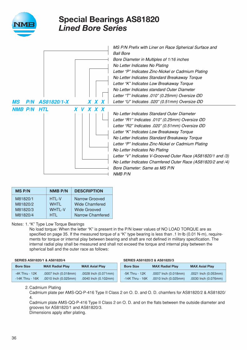
36
Notes: 1. “K” Type Low Torque BearingsNo load torque: When the letter “K” is present in the P/N lower values of NO LOAD TORQUE are asspecified on page 35. If the measured torque of a “K” type bearing is less than .1 ln·lb (0.01 N-m), require-ments for torque or internal play between bearing and shaft are not defined in military specification. Theinternal radial play shall be measured and shall not exceed the torque and internal play between thespherical ball and the outer race as follows:
2. Cadmium PlatingCadmium plate per AMS-QQ-P-416 Type II Class 2 on O. D. and O. D. chamfers for AS81820/2 & AS81820/4.Cadmium plate AMS-QQ-P-416 Type II Class 2 on O. D. and on the flats between the outside diameter andgrooves for AS81820/1 and AS81820/3.Dimensions apply after plating.
Special Bearings AS81820Lined Bore Series
MS P/N Prefix with Liner on Race Spherical Surface andBall BoreBore Diameter in Multiples of 1/16 inchesNo Letter Indicates No PlatingLetter “P” Indicates Zinc-Nickel or Cadmium PlatingNo Letter Indicates Standard Breakaway TorqueLetter “K” Indicates Low Breakaway TorqueNo Letter Indicates standard Outer DiameterLetter “T” Indicates .010” (0.25mm) Oversize ØDLetter “U” Indicates .020” (0.51mm) Oversize ØD
No Letter Indicates Standard Outer DiameterLetter “R1” Indicates .010” (0.25mm) Oversize ØDLetter “R2” Indicates .020” (0.51mm) Oversize ØDLetter “K” Indicates Low Breakaway TorqueNo Letter Indicates Standard Breakaway TorqueLetter “P” Indicates Zinc-Nickel or Cadmium PlatingNo Letter Indicates No PlatingLetter “V” Indicates V-Grooved Outer Race (AS81820/1 and /3)No Letter Indicates Chamfered Outer Race (AS81820/2 and /4)Bore Diameter: Same as MS P/NNMB P/N
MS P/N AS81820/1-X X X XNMB P/N HTL X V X X X
MS P/N NMB P/N DESCRIPTION
M81820/1 HTL-V Narrow GroovedM81820/2 WHTL Wide ChamferedM81820/3 WHTL-V Wide GroovedM81820/4 HTL Narrow Chamfered
SERIES AS81820/2 & AS81820/3
Bore Size MAX Radial Play MAX Axial Play
-5K Thru - 12K .0007 Inch (0.018mm) .0021 Inch (0.053mm)
-14K Thru - 16K .0010 Inch (0.025mm) .0030 Inch (0.076mm)
SERIES AS81820/1 & AS81820/4
Bore Size MAX Radial Play MAX Axial Play
-4K Thru - 12K .0007 Inch (0.018mm) .0028 Inch (0.071mm)
-14K Thru - 16K .0010 Inch (0.025mm) .0040 Inch (0.102mm)
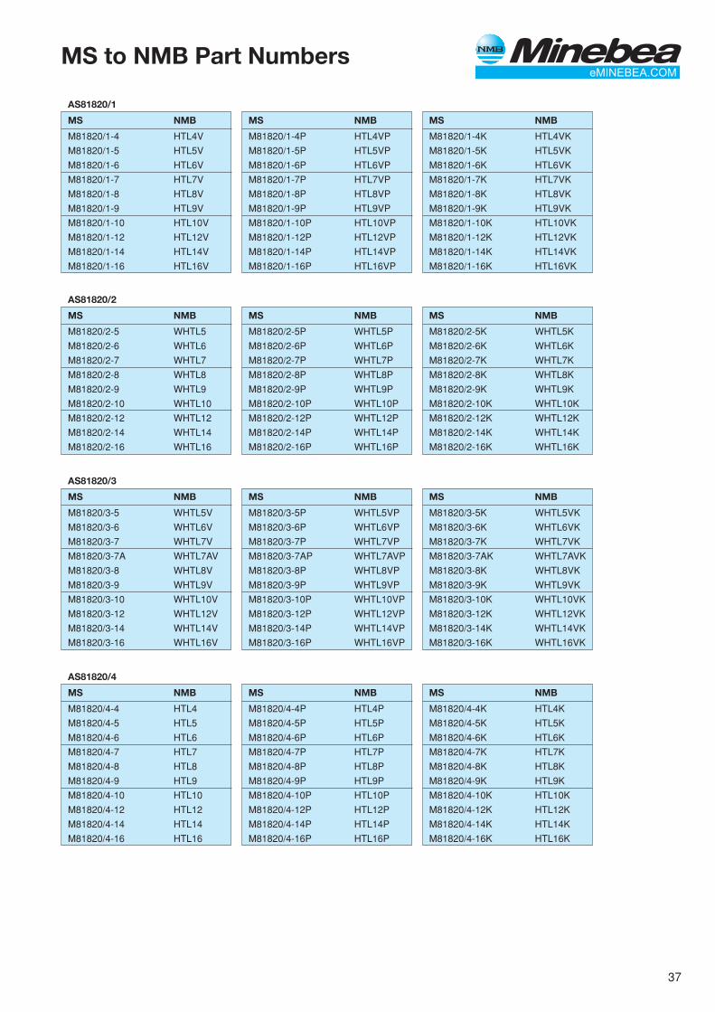
37
MS to NMB Part Numbers
AS81820/2
MS NMB
M81820/2-5 WHTL5
M81820/2-6 WHTL6
M81820/2-7 WHTL7
M81820/2-8 WHTL8
M81820/2-9 WHTL9
M81820/2-10 WHTL10
M81820/2-12 WHTL12
M81820/2-14 WHTL14
M81820/2-16 WHTL16
AS81820/1
MS NMB
M81820/1-4 HTL4V
M81820/1-5 HTL5V
M81820/1-6 HTL6V
M81820/1-7 HTL7V
M81820/1-8 HTL8V
M81820/1-9 HTL9V
M81820/1-10 HTL10V
M81820/1-12 HTL12V
M81820/1-14 HTL14V
M81820/1-16 HTL16V
AS81820/3
MS NMB
M81820/3-5 WHTL5V
M81820/3-6 WHTL6V
M81820/3-7 WHTL7V
M81820/3-7A WHTL7AV
M81820/3-8 WHTL8V
M81820/3-9 WHTL9V
M81820/3-10 WHTL10V
M81820/3-12 WHTL12V
M81820/3-14 WHTL14V
M81820/3-16 WHTL16V
MS NMB
M81820/1-4P HTL4VP
M81820/1-5P HTL5VP
M81820/1-6P HTL6VP
M81820/1-7P HTL7VP
M81820/1-8P HTL8VP
M81820/1-9P HTL9VP
M81820/1-10P HTL10VP
M81820/1-12P HTL12VP
M81820/1-14P HTL14VP
M81820/1-16P HTL16VP
MS NMB
M81820/1-4K HTL4VK
M81820/1-5K HTL5VK
M81820/1-6K HTL6VK
M81820/1-7K HTL7VK
M81820/1-8K HTL8VK
M81820/1-9K HTL9VK
M81820/1-10K HTL10VK
M81820/1-12K HTL12VK
M81820/1-14K HTL14VK
M81820/1-16K HTL16VK
MS NMB
M81820/2-5P WHTL5P
M81820/2-6P WHTL6P
M81820/2-7P WHTL7P
M81820/2-8P WHTL8P
M81820/2-9P WHTL9P
M81820/2-10P WHTL10P
M81820/2-12P WHTL12P
M81820/2-14P WHTL14P
M81820/2-16P WHTL16P
MS NMB
M81820/2-5K WHTL5K
M81820/2-6K WHTL6K
M81820/2-7K WHTL7K
M81820/2-8K WHTL8K
M81820/2-9K WHTL9K
M81820/2-10K WHTL10K
M81820/2-12K WHTL12K
M81820/2-14K WHTL14K
M81820/2-16K WHTL16K
MS NMB
M81820/3-5P WHTL5VP
M81820/3-6P WHTL6VP
M81820/3-7P WHTL7VP
M81820/3-7AP WHTL7AVP
M81820/3-8P WHTL8VP
M81820/3-9P WHTL9VP
M81820/3-10P WHTL10VP
M81820/3-12P WHTL12VP
M81820/3-14P WHTL14VP
M81820/3-16P WHTL16VP
MS NMB
M81820/3-5K WHTL5VK
M81820/3-6K WHTL6VK
M81820/3-7K WHTL7VK
M81820/3-7AK WHTL7AVK
M81820/3-8K WHTL8VK
M81820/3-9K WHTL9VK
M81820/3-10K WHTL10VK
M81820/3-12K WHTL12VK
M81820/3-14K WHTL14VK
M81820/3-16K WHTL16VK
AS81820/4
MS NMB
M81820/4-4 HTL4
M81820/4-5 HTL5
M81820/4-6 HTL6
M81820/4-7 HTL7
M81820/4-8 HTL8
M81820/4-9 HTL9
M81820/4-10 HTL10
M81820/4-12 HTL12
M81820/4-14 HTL14
M81820/4-16 HTL16
MS NMB
M81820/4-4K HTL4K
M81820/4-5K HTL5K
M81820/4-6K HTL6K
M81820/4-7K HTL7K
M81820/4-8K HTL8K
M81820/4-9K HTL9K
M81820/4-10K HTL10K
M81820/4-12K HTL12K
M81820/4-14K HTL14K
M81820/4-16K HTL16K
MS NMB
M81820/4-4P HTL4P
M81820/4-5P HTL5P
M81820/4-6P HTL6P
M81820/4-7P HTL7P
M81820/4-8P HTL8P
M81820/4-9P HTL9P
M81820/4-10P HTL10P
M81820/4-12P HTL12P
M81820/4-14P HTL14P
M81820/4-16P HTL16P
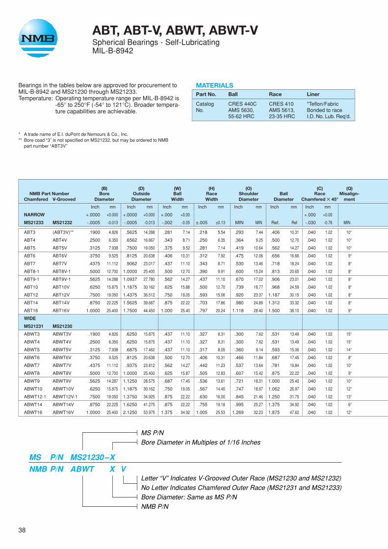
38
ABT, ABT-V, ABWT, ABWT-VSpherical Bearings - Self-LubricatingMIL-B-8942
Bearings in the tables below are approved for procurement toMIL-B-8942 and MS21230 through MS21233.Temperature: Operating temperature range per MIL-B-8942 is
-65° to 250°F (-54° to 121°C). Broader tempera-ture capabilities are achievable.
* A trade name of E.I. duPont de Nemours & Co., Inc.** Bore coad “3” is not specified on MS21232, but may be ordered to NMB
part number “ABT3V”
MS P/NBore Diameter in Multiples of 1/16 Inches
Letter “V” Indicates V-Grooved Outer Race (MS21230 and MS21232)No Letter Indicates Chamfered Outer Race (MS21231 and MS21233)Bore Diameter: Same as MS P/NNMB P/N
MS P/N MS21230–XNMB P/N ABWT X V
(B) (D) (W) (H) (O) (C) (Q)NMB Part Number Bore Outside Ball Race Shoulder Ball Race Misalign-
Chamfered V-Grooved Diameter Diameter Width Width Diameter Diameter Chamfered ✕ 45° ment
Inch mm Inch mm Inch mm Inch mm Inch mm Inch mm Inch mm
NARROW +.0000 +0.000 +.0000 +0.000 +.000 +0.00 +.000 +0.00
MS21233 MS21232 -.0005 -0.013 -.0005 -0.013 -.002 -0.05 ±.005 ±0.13 MIN MIN Ref. Ref. -.030 -0.76 MIN
ABT3 (ABT3V)** .1900 4.826 .5625 14.288 .281 7.14 .218 5.54 .293 7.44 .406 10.31 .040 1.02 10°
ABT4 ABT4V .2500 6.350 .6562 16.667 .343 8.71 .250 6.35 .364 9.25 .500 12.70 .040 1.02 10°
ABT5 ABT5V .3125 7.938 .7500 19.050 .375 9.52 .281 7.14 .419 10.64 .562 14.27 .040 1.02 10°
ABT6 ABT6V .3750 9.525 .8125 20.638 .406 10.31 .312 7.92 .475 12.06 .656 16.66 .040 1.02 9°
ABT7 ABT7V .4375 11.112 .9062 23.017 .437 11.10 .343 8.71 .530 13.46 .718 18.24 .040 1.02 8°
ABT8-1 ABT8V-1 .5000 12.700 1.0000 25.400 .500 12.70 .390 9.91 .600 15.24 .813 20.65 .040 1.02 8°
ABT9-1 ABT9V-1 .5625 14.288 1.0937 27.780 .562 14.27 .437 11.10 .670 17.02 .906 23.01 .040 1.02 8°
ABT10 ABT10V .6250 15.875 1.1875 30.162 .625 15.88 .500 12.70 .739 18.77 .968 24.59 .040 1.02 8°
ABT12 ABT12V .7500 19.050 1.4375 36.512 .750 19.05 .593 15.06 .920 23.37 1.187 30.15 .040 1.02 8°
ABT14 ABT14V .8750 22.225 1.5625 39.687 .875 22.22 .703 17.86 .980 24.89 1.312 33.32 .040 1.02 8°
ABT16 ABT16V 1.0000 25.400 1.7500 44.450 1.000 25.40 .797 20.24 1.118 28.40 1.500 38.10 .040 1.02 9°
WIDE
MS21231 MS21230
ABWT3 ABWT3V .1900 4.826 .6250 15.875 .437 11.10 .327 8.31 .300 7.62 .531 13.49 .040 1.02 15°
ABWT4 ABWT4V .2500 6.350 .6250 15.875 .437 11.10 .327 8.31 .300 7.62 .531 13.49 .040 1.02 15°
ABWT5 ABWT5V .3125 7.938 .6875 17.462 .437 11.10 .317 8.05 .360 9.14 .593 15.06 .040 1.02 14°
ABWT6 ABWT6V .3750 9.525 .8125 20.638 .500 12.70 .406 10.31 .466 11.84 .687 17.45 .040 1.02 8°
ABWT7 ABWT7V .4375 11.112 .9375 23.812 .562 14.27 .442 11.23 .537 13.64 .781 19.84 .040 1.02 10°
ABWT8 ABWT8V .5000 12.700 1.0000 25.400 .625 15.87 .505 12.83 .607 15.42 .875 22.22 .040 1.02 9°
ABWT9 ABWT9V .5625 14.287 1.1250 28.575 .687 17.45 .536 13.61 .721 18.31 1.000 25.40 .040 1.02 10°
ABWT10 ABWT10V .6250 15.875 1.1875 30.162 .750 19.05 .567 14.40 .747 18.97 1.062 26.97 .040 1.02 12°
ABWT12-1 ABWT12V-1 .7500 19.050 1.3750 34.925 .875 22.22 .630 16.00 .845 21.46 1.250 31.75 .040 1.02 13°
ABWT14 ABWT14V .8750 22.225 1.6250 41.275 .875 22.22 .755 19.18 .995 25.27 1.375 34.92 .040 1.02 6°
ABWT16 ABWT16V 1.0000 25.400 2.1250 53.975 1.375 34.92 1.005 25.53 1.269 32.23 1.875 47.62 .040 1.02 12°
MATERIALSPart No. Ball Race Liner
Catalog CRES 440C CRES 410 *Teflon/FabricNo. AMS 5630, AMS 5613, Bonded to race
55-62 HRC 23-35 HRC I.D. No. Lub. Req’d.
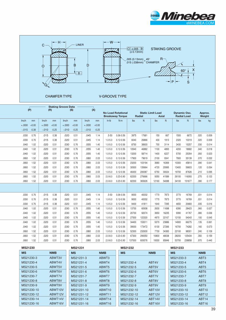
39
MS21232
MS NMB
MS21232-4 ABT4V
MS21232-5 ABT5V
MS21232-6 ABT6V
MS21232-7 ABT7V
MS21232-8 ABT8V
MS21232-9 ABT9V
MS21232-10 ABT10V
MS21232-12 ABT12V
MS21232-14 ABT14V
MS21232-16 ABT16V
H W
- B -
R
V-GROOVE TYPE
STAKING GROOVE
CHAMFER TYPE
P
X
S
60°DBO
Q
LINERCBØ.005
(Ø 0.13mm)
.005 (0.13mm)
.015 (.038mm)45°CHAMFER
✕
Staking Groove Data(P) (R) (S) (X)
No Load Rotational Static Limit Load Dynamic Osc. Approx.Breakaway Torque Radial Axial Radial Load Weight
Inch mm Inch mm Inch mm Inch mm In-lb N-m lbs N lbs N lbs N lbs kg
+.000 +0.00 +.000 +0.00 +.000 +0.00 +.000 +0.00
-.015 -0.38 -.010 -0.25 -.010 -0.25 -.010 -0.25
.030 0.76 .015 0.38 .020 0.51 .045 1.14 .5-50 0.06-0.56 3975 17681 150 667 1500 6672 .020 0.009
.030 0.76 .015 0.38 .020 0.51 .045 1.14 1.0-5.0 0.12-0.56 6040 26866 430 1913 2320 10319 .020 0.009
.040 1.02 .020 0.51 .030 0.76 .055 1.40 1.0-5.0 0.12-0.56 8750 38920 700 3114 3430 15257 .030 0.014
.040 1.02 .020 0.51 .030 0.76 .055 1.40 1.0-5.0 0.12-0.56 10540 46882 1100 4893 4200 18682 .040 0.018
.040 1.02 .020 0.51 .030 0.76 .055 1.40 1.0-5.0 0.12-0.56 13200 58714 1400 6227 5700 25354 .050 0.023
.060 1.52 .020 0.51 .030 0.76 .080 2.03 1.0-5.0 0.12-0.56 17900 79619 2100 9341 7900 35139 .070 0.032
.060 1.52 .020 0.51 .030 0.76 .080 2.03 1.0-5.0 0.12-0.56 23200 103194 3680 16369 10300 45814 .090 0.041
.060 1.52 .020 0.51 .030 0.76 .080 2.03 1.0-5.0 0.12-0.56 30500 135664 4720 20995 13400 59603 .120 0.054
.060 1.52 .020 0.51 .030 0.76 .080 2.03 1.0-5.0 0.12-0.56 46400 206387 6750 30024 19700 87626 .210 0.095
.060 1.52 .020 0.51 .030 0.76 .080 2.03 2.0-8.0 0.23-0.90 62200 276666 9350 41589 26100 116093 .270 0.122
.060 1.52 .020 0.51 .030 0.76 .080 2.03 2.0-8.0 0.23-0.90 82200 365626 12160 54088 34100 151677 .390 0.177
.030 0.76 .015 0.38 .020 0.51 .045 1.14 .5-50 0.06-0.56 9000 40032 1770 7873 3770 16769 .031 0.014
.030 0.76 .015 0.38 .020 0.51 .045 1.14 1.0-5.0 0.12-0.56 9000 40032 1770 7873 3770 16769 .031 0.014
.030 0.76 .015 0.38 .020 0.51 .045 1.14 1.0-5.0 0.12-0.56 9400 41811 1640 7295 4650 20683 .035 0.016
.040 1.02 .020 0.51 .030 0.76 .055 1.40 1.0-5.0 0.12-0.56 13700 60938 2630 11698 6390 28423 .060 0.027
.040 1.02 .020 0.51 .030 0.76 .055 1.40 1.0-5.0 0.12-0.56 20700 92074 3650 16235 9390 41767 .080 0.036
.040 1.02 .020 0.51 .030 0.76 .055 1.40 1.0-5.0 0.12-0.56 27500 122320 4970 22107 12150 54043 .100 0.045
.040 1.02 .020 0.51 .030 0.76 .055 1.40 1.0-5.0 0.12-0.56 34400 153011 5370 23886 14900 66275 .135 0.061
.040 1.02 .020 0.51 .030 0.76 .055 1.40 1.0-5.0 0.12-0.56 39000 173472 6130 27266 16700 74282 .160 0.073
.060 1.52 .020 0.51 .030 0.76 .080 2.03 1.0-5.0 0.12-0.56 52300 232630 7730 34383 22100 98301 .240 0.109
.060 1.52 .020 0.51 .030 0.76 .080 2.03 2.0-8.0 0.23-0.90 67300 299350 10800 48038 28200 125434 .350 0.159
.060 1.52 .020 0.51 .030 0.76 .080 2.03 2.0-8.0 0.23-0.90 137000 609376 19300 85846 53700 238858 .970 0.440
MS21231
MS NMB
MS21231-3 ABWT3
MS21231-4 ABWT4
MS21231-5 ABWT5
MS21231-6 ABWT6
MS21231-7 ABWT7
MS21231-8 ABWT8
MS21231-9 ABWT9
MS21231-10 ABWT10
MS21231-12 ABWT11
MS21231-14 ABWT14
MS21231-16 ABWT16
MS21233
MS NMB
MS21233-3 ABT3
MS21233-4 ABT4
MS21233-5 ABT5
MS21233-6 ABT6
MS21233-7 ABT7
MS21233-8 ABT8
MS21233-9 ABT9
MS21233-10 ABT10
MS21233-12 ABT12
MS21233-14 ABT14
MS21233-16 ABT16
MS21230
MS NMB
MS21230-3 ABWT3V
MS21230-4 ABWT4V
MS21230-5 ABWT5V
MS21230-6 ABWT6V
MS21230-7 ABWT7V
MS21230-8 ABWT8V
MS21230-9 ABWT9V
MS21230-10 ABWT10V
MS21230-12 ABWT12V
MS21230-14 ABWT14V
MS21230-16 ABWT16V
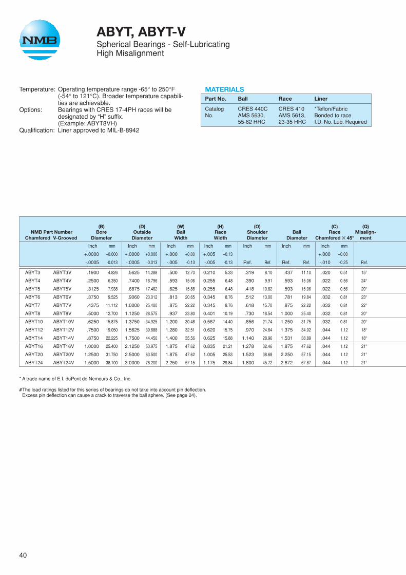
40
ABYT, ABYT-VSpherical Bearings - Self-LubricatingHigh Misalignment
Temperature: Operating temperature range -65° to 250°F(-54° to 121°C). Broader temperature capabili-ties are achievable.
Options: Bearings with CRES 17-4PH races will bedesignated by “H” suffix.(Example: ABYT8VH)
Qualification: Liner approved to MIL-B-8942
(B) (D) (W) (H) (O) (C) (Q)NMB Part Number Bore Outside Ball Race Shoulder Ball Race Misalign-
Chamfered V-Grooved Diameter Diameter Width Width Diameter Diameter Chamfered ✕ 45° ment
Inch mm Inch mm Inch mm Inch mm Inch mm Inch mm Inch mm
+.0000 +0.000 +.0000 +0.000 +.000 +0.00 +.005 +0.13 +.000 +0.00
-.0005 -0.013 -.0005 -0.013 -.005 -0.13 -.005 -0.13 Ref. Ref. Ref. Ref. -.010 -0.25 Ref.
ABYT3 ABYT3V .1900 4.826 .5625 14.288 .500 12.70 0.210 5.33 .319 8.10 .437 11.10 .020 0.51 15°
ABYT4 ABYT4V .2500 6.350 .7400 18.796 .593 15.06 0.255 6.48 .390 9.91 .593 15.06 .022 0.56 24°
ABYT5 ABYT5V .3125 7.938 .6875 17.462 .625 15.88 0.255 6.48 .418 10.62 .593 15.06 .022 0.56 20°
ABYT6 ABYT6V .3750 9.525 .9060 23.012 .813 20.65 0.345 8.76 .512 13.00 .781 19.84 .032 0.81 23°
ABYT7 ABYT7V .4375 11.112 1.0000 25.400 .875 22.22 0.345 8.76 .618 15.70 .875 22.22 .032 0.81 22°
ABYT8 ABYT8V .5000 12.700 1.1250 28.575 .937 23.80 0.401 10.19 .730 18.54 1.000 25.40 .032 0.81 20°
ABYT10 ABYT10V .6250 15.875 1.3750 34.925 1.200 30.48 0.567 14.40 .856 21.74 1.250 31.75 .032 0.81 20°
ABYT12 ABYT12V .7500 19.050 1.5625 39.688 1.280 32.51 0.620 15.75 .970 24.64 1.375 34.92 .044 1.12 18°
ABYT14 ABYT14V .8750 22.225 1.7500 44.450 1.400 35.56 0.625 15.88 1.140 28.96 1.531 38.89 .044 1.12 18°
ABYT16 ABYT16V 1.0000 25.400 2.1250 53.975 1.875 47.62 0.835 21.21 1.278 32.46 1.875 47.62 .044 1.12 21°
ABYT20 ABYT20V 1.2500 31.750 2.5000 63.500 1.875 47.62 1.005 25.53 1.523 38.68 2.250 57.15 .044 1.12 21°
ABYT24 ABYT24V 1.5000 38.100 3.0000 76.200 2.250 57.15 1.175 29.84 1.800 45.72 2.672 67.87 .044 1.12 21°
* A trade name of E.I. duPont de Nemours & Co., Inc.
#The load ratings listed for this series of bearings do not take into account pin deflection.Excess pin deflection can cause a crack to traverse the ball sphere. (See page 24).
MATERIALSPart No. Ball Race Liner
Catalog CRES 440C CRES 410 *Teflon/FabricNo. AMS 5630, AMS 5613, Bonded to race
55-62 HRC 23-35 HRC I.D. No. Lub. Required
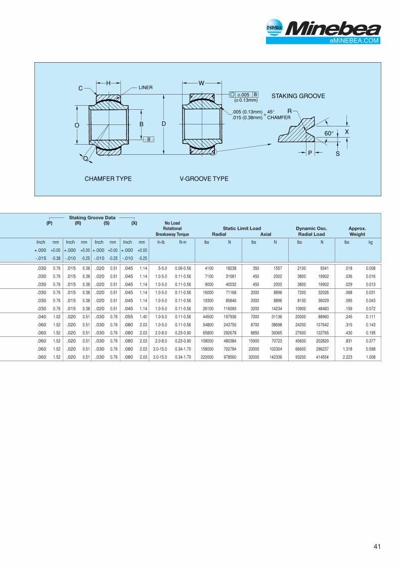
41
H W
- B -
R
V-GROOVE TYPE
STAKING GROOVE
CHAMFER TYPE
P
X
S
60°DBO
Q
LINERCBØ.005
(Ø 0.13mm)
.005 (0.13mm)
.015 (0.38mm)45°CHAMFER
✕
Staking Groove Data(P) (R) (S) (X) No Load
Rotational Static Limit Load Dynamic Osc. Approx.Breakaway Torque Radial Axial Radial Load Weight
Inch mm Inch mm Inch mm Inch mm In-lb N-m lbs N lbs N lbs N lbs kg
+.000 +0.00 +.000 +0.00 +.000 +0.00 +.000 +0.00
-.015 -0.38 -.010 -0.25 -.010 -0.25 -.010 -0.25
.030 0.76 .015 0.38 .020 0.51 .045 1.14 .5-5.0 0.06-0.56 4100 18238 350 1557 2100 9341 .018 0.008
.030 0.76 .015 0.38 .020 0.51 .045 1.14 1.0-5.0 0.11-0.56 7100 31581 450 2002 3800 16902 .036 0.016
.030 0.76 .015 0.38 .020 0.51 .045 1.14 1.0-5.0 0.11-0.56 9000 40032 450 2002 3800 16902 .029 0.013
.030 0.76 .015 0.38 .020 0.51 .045 1.14 1.0-5.0 0.11-0.56 16000 71168 2000 8896 7200 32026 .068 0.031
.030 0.76 .015 0.38 .020 0.51 .045 1.14 1.0-5.0 0.11-0.56 19300 85846 2000 8896 8100 36029 .095 0.043
.030 0.76 .015 0.38 .020 0.51 .045 1.14 1.0-5.0 0.11-0.56 26100 116093 3200 14234 10900 48483 .159 0.072
.040 1.02 .020 0.51 .030 0.76 .055 1.40 1.0-5.0 0.11-0.56 44500 197936 7000 31136 20000 88960 .245 0.111
.060 1.52 .020 0.51 .030 0.76 .080 2.03 1.0-5.0 0.11-0.56 54800 243750 8700 38698 24200 107642 .315 0.143
.060 1.52 .020 0.51 .030 0.76 .080 2.03 2.0-8.0 0.23-0.90 65800 292678 8850 39365 27600 122765 .430 0.195
.060 1.52 .020 0.51 .030 0.76 .080 2.03 2.0-8.0 0.23-0.90 108000 480384 15900 70723 45600 202829 .831 0.377
.060 1.52 .020 0.51 .030 0.76 .080 2.03 3.0-15.0 0.34-1.70 158000 702784 23000 102304 66600 296237 1.318 0.598
.060 1.52 .020 0.51 .030 0.76 .080 2.03 3.0-15.0 0.34-1.70 220000 978560 32000 142336 93200 414554 2.223 1.008
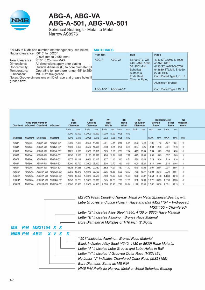
42
ABG-A, ABG-VAABG-A-501, ABG-VA-501Spherical Bearings - Metal to MetalNarrow AS8976
For MS to NMB part number interchangeablity, see below.Radial Clearance: .0010” to .0020”
(0.025 mm to 0.051 mm)Axial Clearance: .010” (0.25 mm) MAXDimensions: All dimensions apply after platingConcentricity: Outside diameter (D) to bore diameter (B) within .005” (0.13mm) FIMTemperature: Operating temperature range -65° to 250°F (-54° to 121°C)Lubrication: MIL-G-21164 greaseNotes: Groove dimensions on ID of race and grease holes thru race are before bearing assembly, but swaging shall not restrictgrease flow.
MS P/N Prefix Denoting Narrow, Metal on Metal Spherical Bearing withLube Grooves and Lube Holes in Race and Ball (MS21154 = V-Grooved,
MS21155 = Chamfered)Letter “S” Indicates Alloy Steel (4340, 4130 or 8630) Race MaterialLetter “B” Indicates Aluminum Bronze Race MaterialBore Diameter in Multiples of 1/16 Inch (2 Digits)
“-501” Indicates Aluminum Bronze Race MaterialBlank Indicates Alloy Steel (4340, 4130 or 8630) Race MaterialLetter “A” Indicates Lube Groove and Lube Holes in BallLetter “V” Indicates V-Grooved Outer Race (MS21154)No Letter “V” Indicates Chamfered Outer Race (MS21155)Bore Diameter: Same as MS P/NNMB P/N Prefix for Narrow, Metal on Metal Spherical Bearing
MS P/N MS21154 X XNMB P/N ABG X V X X
MATERIALSPart No. Ball Race
ABG-A ABG-VA 52100 STL. OR 4340 STL/AMS-S-5000440C/AMS 5630, or AMS 641556 HRC MIN, 4130 STL/AMS-S-6758Spherical or 8630 STL/MIL-S-6050,Surface & 27-36 HRCEnds Hard Cad. Plated Type I, CL. 2Chrome Plated
Aluminium Bronze
ABG-A-501 ABG-VA-501 Cad. Plated Type I, CL. 2
(B) (D) (W) (H) (O) Ball Diameter (Q)NMB Part Number Bore Outside Ball Race Shoulder Bronze Steel Misalign-
Chamfered V-Grooved Chamfered V-Grooved Diameter Diameter Width Width Diameter Race Race ment
Inch mm Inch mm Inch mm Inch mm Inch mm Inch mm Inch mm
+.0000 +0.000 +.0000 +0.000 +.000 +0.00 +.005 +0.13
MS21155S MS21154S MS21155B MS21154B -.0005 -0.013 -.0005 -0.013 -.002 -0.05 -.005 -0.13 MAX MAX MAX MAX MIN
ABG3A ABG3VA ABG3A-501 ABG3VA-501 .1900 4.826 .5625 14.288 .281 7.14 .218 5.54 .293 7.44 .438 11.13 .407 10.34 10°
ABG4A ABG4VA ABG4A-501 ABG4VA-501 .2500 6.350 .6562 16.667 .343 8.71 .250 6.35 .364 9.25 .501 12.73 .501 12.73 10°
ABG5A ABG5VA ABG5A-501 ABG5VA-501 .3125 7.938 .7500 19.050 .375 9.52 .281 7.14 .419 10.64 .594 15.09 .563 14.30 10°
ABG6A ABG6VA ABG6A-501 ABG6VA-501 .3750 9.525 .8125 20.638 .406 10.31 .312 7.92 .475 12.06 .657 16.69 .657 16.69 9°
ABG7A ABG7VA ABG7A-501 ABG7VA-501 .4375 11.112 .9062 23.017 .437 11.10 .343 8.71 .530 13.46 .719 18.26 .719 18.26 8°
ABG8A ABG8VA ABG8A-501 ABG8VA-501 .5000 12.700 1.0000 25.400 .500 12.70 .390 9.91 .600 15.24 .814 20.68 .814 20.68 8°
ABG9A ABG9VA ABG9A-501 ABG9VA-501 .5625 14.288 1.0937 27.780 .562 14.27 .437 11.10 .670 17.02 .907 23.04 .907 23.04 8°
ABG10A ABG10VA ABG10A-501 ABG10VA-501 .6250 15.875 1.1875 30.162 .625 15.88 .500 12.70 .739 18.77 1.001 25.43 .970 24.64 8°
ABG12A ABG12VA ABG12A-501 ABG12VA-501 .7500 19.050 1.4375 36.512 .750 19.05 .593 15.06 .920 23.37 1.251 31.78 1.188 30.18 8°
ABG14A ABG14VA ABG14A-501 ABG14VA-501 .8750 22.225 1.5625 39.688 .875 22.22 .703 17.86 .980 24.89 1.376 34.95 1.313 33.35 8°
ABG16A ABG16VA ABG16A-501 ABG16VA-501 1.0000 25.400 1.7500 44.450 1.000 25.40 .797 20.24 1.118 28.40 1.563 39.70 1.501 38.13 9°
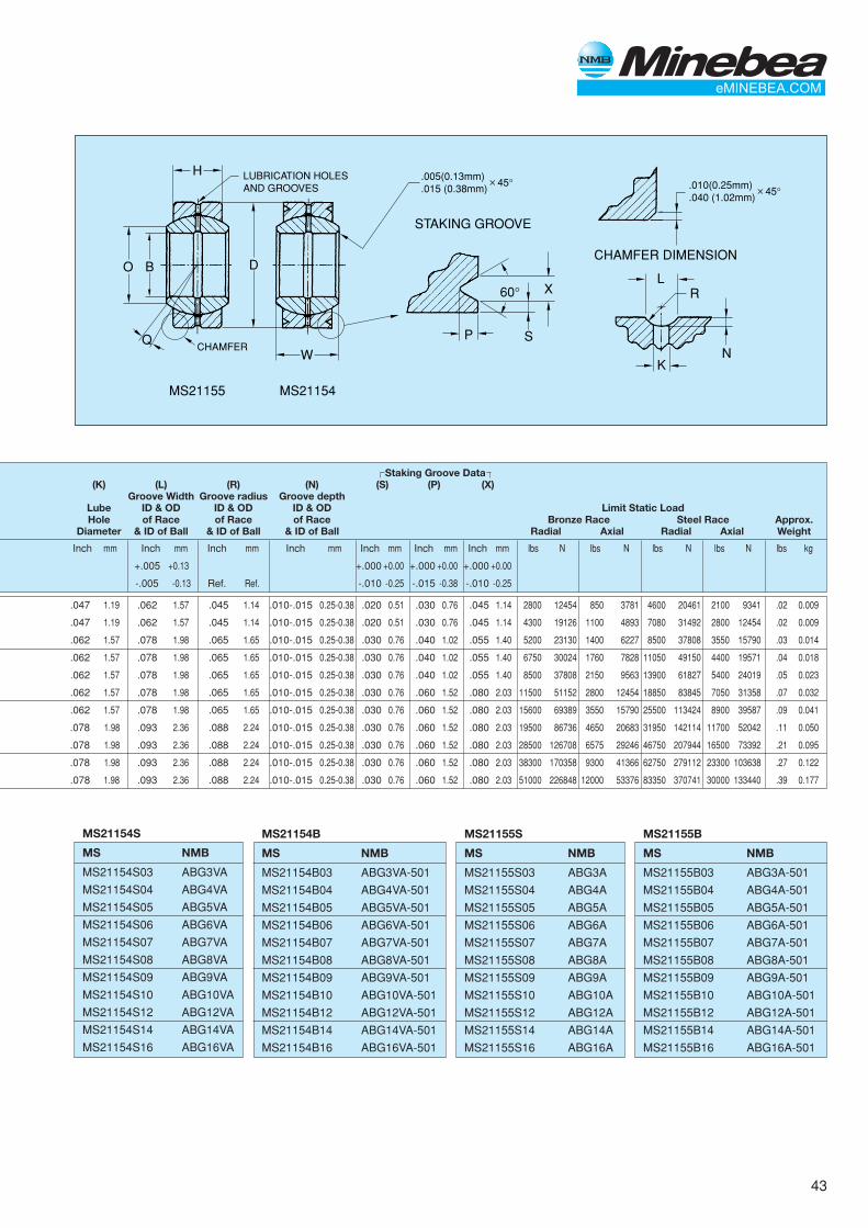
43
H
W
MS21154
STAKING GROOVE
CHAMFER DIMENSION
MS21155
P
X
S
60°
DO
Q
B
LUBRICATION HOLESAND GROOVES
L
KN
R
.010(0.25mm)
.040 (1.02mm)45°✕
.005(0.13mm)
.015 (0.38mm)45°✕
CHAMFER
MS21154B
MS NMB
MS21154B03 ABG3VA-501
MS21154B04 ABG4VA-501
MS21154B05 ABG5VA-501
MS21154B06 ABG6VA-501
MS21154B07 ABG7VA-501
MS21154B08 ABG8VA-501
MS21154B09 ABG9VA-501
MS21154B10 ABG10VA-501
MS21154B12 ABG12VA-501
MS21154B14 ABG14VA-501
MS21154B16 ABG16VA-501
MS21155B
MS NMB
MS21155B03 ABG3A-501
MS21155B04 ABG4A-501
MS21155B05 ABG5A-501
MS21155B06 ABG6A-501
MS21155B07 ABG7A-501
MS21155B08 ABG8A-501
MS21155B09 ABG9A-501
MS21155B10 ABG10A-501
MS21155B12 ABG12A-501
MS21155B14 ABG14A-501
MS21155B16 ABG16A-501
MS21155S
MS NMB
MS21155S03 ABG3A
MS21155S04 ABG4A
MS21155S05 ABG5A
MS21155S06 ABG6A
MS21155S07 ABG7A
MS21155S08 ABG8A
MS21155S09 ABG9A
MS21155S10 ABG10A
MS21155S12 ABG12A
MS21155S14 ABG14A
MS21155S16 ABG16A
MS21154S
MS NMB
MS21154S03 ABG3VA
MS21154S04 ABG4VA
MS21154S05 ABG5VA
MS21154S06 ABG6VA
MS21154S07 ABG7VA
MS21154S08 ABG8VA
MS21154S09 ABG9VA
MS21154S10 ABG10VA
MS21154S12 ABG12VA
MS21154S14 ABG14VA
MS21154S16 ABG16VA
Staking Groove Data(K) (L) (R) (N) (S) (P) (X)
Groove Width Groove radius Groove depthLube ID & OD ID & OD ID & OD Limit Static LoadHole of Race of Race of Race Bronze Race Steel Race Approx.
Diameter & ID of Ball & ID of Ball & ID of Ball Radial Axial Radial Axial Weight
Inch mm Inch mm Inch mm Inch mm Inch mm Inch mm Inch mm lbs N lbs N lbs N lbs N lbs kg
+.005 +0.13 +.000 +0.00 +.000 +0.00 +.000 +0.00
-.005 -0.13 Ref. Ref. -.010 -0.25 -.015 -0.38 -.010 -0.25
.047 1.19 .062 1.57 .045 1.14 .010-.015 0.25-0.38 .020 0.51 .030 0.76 .045 1.14 2800 12454 850 3781 4600 20461 2100 9341 .02 0.009
.047 1.19 .062 1.57 .045 1.14 .010-.015 0.25-0.38 .020 0.51 .030 0.76 .045 1.14 4300 19126 1100 4893 7080 31492 2800 12454 .02 0.009
.062 1.57 .078 1.98 .065 1.65 .010-.015 0.25-0.38 .030 0.76 .040 1.02 .055 1.40 5200 23130 1400 6227 8500 37808 3550 15790 .03 0.014
.062 1.57 .078 1.98 .065 1.65 .010-.015 0.25-0.38 .030 0.76 .040 1.02 .055 1.40 6750 30024 1760 7828 11050 49150 4400 19571 .04 0.018
.062 1.57 .078 1.98 .065 1.65 .010-.015 0.25-0.38 .030 0.76 .040 1.02 .055 1.40 8500 37808 2150 9563 13900 61827 5400 24019 .05 0.023
.062 1.57 .078 1.98 .065 1.65 .010-.015 0.25-0.38 .030 0.76 .060 1.52 .080 2.03 11500 51152 2800 12454 18850 83845 7050 31358 .07 0.032
.062 1.57 .078 1.98 .065 1.65 .010-.015 0.25-0.38 .030 0.76 .060 1.52 .080 2.03 15600 69389 3550 15790 25500 113424 8900 39587 .09 0.041
.078 1.98 .093 2.36 .088 2.24 .010-.015 0.25-0.38 .030 0.76 .060 1.52 .080 2.03 19500 86736 4650 20683 31950 142114 11700 52042 .11 0.050
.078 1.98 .093 2.36 .088 2.24 .010-.015 0.25-0.38 .030 0.76 .060 1.52 .080 2.03 28500 126708 6575 29246 46750 207944 16500 73392 .21 0.095
.078 1.98 .093 2.36 .088 2.24 .010-.015 0.25-0.38 .030 0.76 .060 1.52 .080 2.03 38300 170358 9300 41366 62750 279112 23300 103638 .27 0.122
.078 1.98 .093 2.36 .088 2.24 .010-.015 0.25-0.38 .030 0.76 .060 1.52 .080 2.03 51000 226848 12000 53376 83350 370741 30000 133440 .39 0.177

44
ABC-G, ABC-VG, ABC-GA, ABC-VGASpherical Bearings - Metal to MetalBeryllium Copper Ball, AS81936
For MS to NMB part number interchangeablity, see below.Radial Clearance: Free turning to .001” (0.025mm) MAXAxial Clearance: Free turning to .005” (0.127mm) MAXConcentricity: Outside diameter (D) and pitch diameter (E)
to bore diameter (B) within .005” (0.13mm)FIM Bearings prepacked with MIL-PRF-81322
Temperature: Operating temperature range -65° to 350°F(-54° to 177°C)
Notes: Groove dimensions on ID of race and grease holes thrurace are before bearings assembly, but swaging shall notrestrict grease flow.
MATERIALSBall Race
BeCu/ASTM B 196, CRES 17-4PH/AMS 5643,TEMPER TH04, Cond. H-115037 HRC MIN
LUBRICATION PROVISIONSABC-G & ABC-VG Lubrication grooves in race and 3 equally
speced holes through race only.ABC-GA ABC-VGA Lubrication grooves in race and bore of
ball and 3 equally spaced holes throughrace and ball.
(B) (D) (W) (H) (O) (Q)NMB Part Number Bore Outside Ball Race Shoulder Ball Misalign-
Chamfered V-Grooved Chamfered V-Grooved Diameter Diameter Width Width Diameter Diameter ment
Inch mm Inch mm Inch mm Inch mm Inch mm Inch mm
+.0000 +0.000 +.0000 +0.000 +.000 +0.00 +.000 +0.00
M81936/2-R M81936/1-R M81936/2- M81936/1- -.0005 -0.013 -.0005 -0.013 -.005 -0.13 -.005 -0.13 MIN MIN MAX MAX MIN
ABC4G ABC4VG ABC4GA ABC4VGA .2500 6.350 .6562 16.667 .343 8.71 .250 6.35 .357 9.53 .501 12.73 12°
ABC5G ABC5VG ABC5GA ABC5VGA .3125 7.938 .7500 19.050 .375 9.52 .281 7.14 .413 10.49 .563 14.30 11°
ABC6G ABC6VG ABC6GA ABC6VGA .3750 9.525 .8125 20.638 .406 10.31 .312 7.92 .509 12.93 .657 16.69 9°
ABC7G ABC7VG ABC7GA ABC7VGA .4375 11.112 .9062 23.017 .437 11.10 .343 8.71 .563 14.30 .719 18.26 8°
ABC8G ABC8VG ABC8GA ABC8VGA .5000 12.700 1.0000 25.400 .500 12.70 .390 9.91 .634 16.10 .814 20.68 8°
ABC9G ABC9VG ABC9GA ABC9VGA .5625 14.288 1.0937 27.780 .562 14.27 .437 11.10 .664 16.87 .876 22.25 8°
ABC10G ABC10VG ABC10GA ABC10VGA .6250 15.875 1.1875 30.162 .625 15.88 .500 12.70 .732 18.59 .969 24.61 8°
ABC12G ABC12VG ABC12GA ABC12VGA .7500 19.050 1.4375 36.512 .750 19.05 .593 15.06 .913 23.19 1.188 30.18 8°
ABC13G ABC13VG ABC13GA ABC13VGA .8125 20.638 1.5625 39.688 .812 20.62 .650 16.51 .984 24.99 1.282 32.56 8°
ABC14G ABC14VG ABC14GA ABC14VGA .8750 22.225 1.6562 42.067 .875 22.22 .703 17.86 1.054 26.77 1.376 34.95 8°
ABC16G ABC16VG ABC16GA ABC16VGA 1.0000 25.400 1.8750 47.625 1.000 25.40 .797 20.24 1.193 30.30 1.563 39.70 8°
ABC18G ABC18VG ABC18GA ABC18VGA 1.1250 28.575 2.1250 53.975 1.125 28.58 .900 22.86 1.334 33.88 1.751 44.48 8°
ABC20G ABC20VG ABC20GA ABC20VGA 1.2500 31.750 2.3125 58.738 1.250 31.75 1.000 25.40 1.473 37.41 1.938 49.23 8°
ABC22G ABC22VG ABC22GA ABC22VGA 1.3750 34.925 2.5625 65.088 1.375 34.92 1.100 27.94 1.654 42.01 2.157 54.79 8°
ABC24G ABC24VG ABC24GA ABC24VGA 1.5000 38.100 2.8125 71.438 1.500 38.10 1.200 30.48 1.794 45.57 2.345 59.56 8°

45
Staking Groove Data(K) (L) (R) (N) (E) (S) (P)
Groove Width Groove radius Groove depthLube ID & OD ID & OD ID & ODHole of Race of Race of Race Pitch Static Limit Load Approx.
Diameter & ID of Ball & ID of Ball & ID of Ball Diameter Radial Axial Weight
Inch mm Inch mm Inch mm Inch mm Inch mm Inch mm Inch mm lbs N lbs N lbs kg
+.000 +0.00 +.000 +0.00 +.000 +0.00
-.010 -0.25 -.010 -0.25 -.015 -0.38
.032-.062 0.81-1.57 .042-.078 1.07-1.98 .030-.062 0.76-1.57 .010-.015 0.25-0.38 .596 15.14 .020 0.51 .030 0.76 6330 28156 1930 8585 .02 0.009
.042-.062 1.07-1.57 .042-.078 1.07-1.98 .030-.062 0.76-1.57 .010-.015 0.25-0.38 .652 16.56 .030 0.76 .040 1.02 8460 37630 2450 10898 .03 0.014
.042-.062 1.07-1.57 .042-.078 1.07-1.98 .030-.062 0.76-1.57 .010-.015 0.25-0.38 .714 18.14 .030 0.76 .040 1.02 11400 50707 3090 13744 .04 0.018
.052-.062 1.32-1.57 .065-.094 1.65-2.39 .060-.094 1.52-2.39 .010-.015 0.25-0.38 .808 20.52 .030 0.76 .040 1.02 14800 65830 3740 16636 .05 0.023
.052-.062 1.32-1.57 .065-.094 1.65-2.39 .060-.094 1.52-2.39 .010-.015 0.25-0.38 .878 22.30 .030 0.76 .060 1.52 20400 90739 4860 21617 .07 0.032
.052-.062 1.32-1.57 .065-.094 1.65-2.39 .060-.094 1.52-2.39 .010-.015 0.25-0.38 .972 24.69 .030 0.76 .060 1.52 26700 118762 6100 27133 .09 0.041
.062-.078 1.57-1.98 .073-.109 1.85-2.77 .070-.125 1.78-3.18 .010-.015 0.25-0.38 1.065 27.05 .030 0.76 .060 1.52 33100 147229 8080 35940 .11 0.050
.062-.078 1.57-1.98 .073-.109 1.85-2.77 .070-.125 1.78-3.18 .010-.015 0.25-0.38 1.315 33.40 .030 0.76 .060 1.52 50000 222400 11440 50885 .21 0.095
.062-.078 1.57-1.98 .073-.109 1.85-2.77 .070-.125 1.78-3.18 .010-.015 0.25-0.38 1.440 36.58 .030 0.76 .060 1.52 59000 262432 13800 61382 .24 0.109
.062-.078 1.57-1.98 .073-.109 1.85-2.77 .070-.125 1.78-3.18 .010-.015 0.25-0.38 1.534 38.96 .030 0.76 .060 1.52 70300 312694 16160 71880 .27 0.122
.078-.093 1.98-2.36 .082-.109 2.08-2.77 .090-.125 2.29-3.18 .010-.015 0.25-0.38 1.753 44.53 .030 0.76 .060 1.52 77700 345600 20850 92741 .39 0.177
.078-.093 1.98-2.36 .082-.109 2.08-2.77 .090-.125 2.29-3.18 .010-.015 0.25-0.38 2.003 50.88 .030 0.76 .060 1.52 121500 540432 26740 118940 .72 0.327
.078-.093 1.98-2.36 .082-.109 2.08-2.77 .090-.125 2.29-3.18 .010-.015 0.25-0.38 2.190 55.63 .030 0.76 .060 1.52 152000 676096 33065 147073 .93 0.422
.078-.093 1.98-2.36 .082-.109 2.08-2.77 .090-.125 2.29-3.18 .010-.015 0.25-0.38 2.440 61.98 .030 0.76 .060 1.52 186000 827328 40120 178454 1.28 0.581
.078-.093 1.98-2.36 .082-.109 2.08-2.77 .090-.125 2.29-3.18 .010-.015 0.25-0.38 2.690 68.33 .030 0.76 .060 1.52 224000 996352 47820 212703 1.67 0.757
H
W
STAKING GROOVE
CHAMFER DIMENSION
M81936/2-( )RABC-G
M81936/1-( )RABC-VG
M81936/2-( )ABC-GA
M81936/1-( )ABC-VGA P
S
30
E
DO
Q
B
LUBRICATION HOLESAND GROOVES
H
W
DO
Q
B
LUBRICATION HOLESAND GROOVES
L
KN
R
.010(0.25mm)
.040 (1.02mm)45✕
.005 (0.13mm)
.015 (0.38mm)45✕
CHAMFER
20 MIN FOR-4 ONLY30 ALL OTHERS
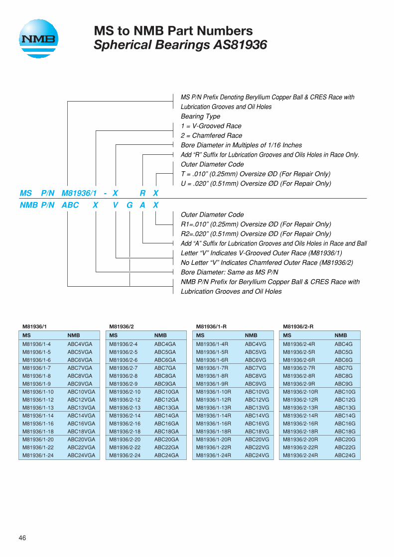
46
MS to NMB Part NumbersSpherical Bearings AS81936
MS P/N Prefix Denoting Beryllium Copper Ball & CRES Race withLubrication Grooves and Oil HolesBearing Type1 = V-Grooved Race2 = Chamfered RaceBore Diameter in Multiples of 1/16 InchesAdd “R” Suffix for Lubrication Grooves and Oils Holes in Race Only.Outer Diameter CodeT = .010” (0.25mm) Oversize ØD (For Repair Only)U = .020” (0.51mm) Oversize ØD (For Repair Only)
Outer Diameter CodeR1=.010” (0.25mm) Oversize ØD (For Repair Only)R2=.020” (0.51mm) Oversize ØD (For Repair Only)Add “A” Suffix for Lubrication Grooves and Oils Holes in Race and BallLetter “V” Indicates V-Grooved Outer Race (M81936/1)No Letter “V” Indicates Chamfered Outer Race (M81936/2)Bore Diameter: Same as MS P/NNMB P/N Prefix for Beryllium Copper Ball & CRES Race withLubrication Grooves and Oil Holes
MS P/N M81936/1 - X R XNMB P/N ABC X V G A X
M81936/2-R
MS NMB
M81936/2-4R ABC4G
M81936/2-5R ABC5G
M81936/2-6R ABC6G
M81936/2-7R ABC7G
M81936/2-8R ABC8G
M81936/2-9R ABC9G
M81936/2-10R ABC10G
M81936/2-12R ABC12G
M81936/2-13R ABC13G
M81936/2-14R ABC14G
M81936/2-16R ABC16G
M81936/2-18R ABC18G
M81936/2-20R ABC20G
M81936/2-22R ABC22G
M81936/2-24R ABC24G
M81936/1
MS NMB
M81936/1-4 ABC4VGA
M81936/1-5 ABC5VGA
M81936/1-6 ABC6VGA
M81936/1-7 ABC7VGA
M81936/1-8 ABC8VGA
M81936/1-9 ABC9VGA
M81936/1-10 ABC10VGA
M81936/1-12 ABC12VGA
M81936/1-13 ABC13VGA
M81936/1-14 ABC14VGA
M81936/1-16 ABC16VGA
M81936/1-18 ABC18VGA
M81936/1-20 ABC20VGA
M81936/1-22 ABC22VGA
M81936/1-24 ABC24VGA
M81936/2
MS NMB
M81936/2-4 ABC4GA
M81936/2-5 ABC5GA
M81936/2-6 ABC6GA
M81936/2-7 ABC7GA
M81936/2-8 ABC8GA
M81936/2-9 ABC9GA
M81936/2-10 ABC10GA
M81936/2-12 ABC12GA
M81936/2-13 ABC13GA
M81936/2-14 ABC14GA
M81936/2-16 ABC16GA
M81936/2-18 ABC18GA
M81936/2-20 ABC20GA
M81936/2-22 ABC22GA
M81936/2-24 ABC24GA
M81936/1-R
MS NMB
M81936/1-4R ABC4VG
M81936/1-5R ABC5VG
M81936/1-6R ABC6VG
M81936/1-7R ABC7VG
M81936/1-8R ABC8VG
M81936/1-9R ABC9VG
M81936/1-10R ABC10VG
M81936/1-12R ABC12VG
M81936/1-13R ABC13VG
M81936/1-14R ABC14VG
M81936/1-16R ABC16VG
M81936/1-18R ABC18VG
M81936/1-20R ABC20VG
M81936/1-22R ABC22VG
M81936/1-24R ABC24VG
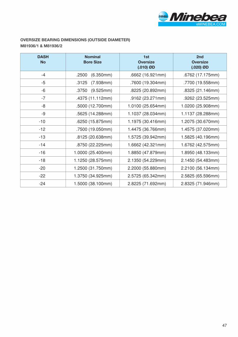
47
OVERSIZE BEARING DIMENSIONS (OUTSIDE DIAMETER)
M81936/1 & M81936/2
DASH Nominal 1st 2ndNo Bore Size Oversize Oversize
(.010) ØD (.020) ØD
-4 .2500 (6.350mm) .6662 (16.921mm) .6762 (17.175mm)
-5 .3125 (7.938mm) .7600 (19.304mm) .7700 (19.558mm)
-6 .3750 (9.525mm) .8225 (20.892mm) .8325 (21.146mm)
-7 .4375 (11.112mm) .9162 (23.271mm) .9262 (23.525mm)
-8 .5000 (12.700mm) 1.0100 (25.654mm) 1.0200 (25.908mm)
-9 .5625 (14.288mm) 1.1037 (28.034mm) 1.1137 (28.288mm)
-10 .6250 (15.875mm) 1.1975 (30.416mm) 1.2075 (30.670mm)
-12 .7500 (19.050mm) 1.4475 (36.766mm) 1.4575 (37.020mm)
-13 .8125 (20.638mm) 1.5725 (39.942mm) 1.5825 (40.196mm)
-14 .8750 (22.225mm) 1.6662 (42.321mm) 1.6762 (42.575mm)
-16 1.0000 (25.400mm) 1.8850 (47.879mm) 1.8950 (48.133mm)
-18 1.1250 (28.575mm) 2.1350 (54.229mm) 2.1450 (54.483mm)
-20 1.2500 (31.750mm) 2.2000 (55.880mm) 2.2100 (56.134mm)
-22 1.3750 (34.925mm) 2.5725 (65.342mm) 2.5825 (65.596mm)
-24 1.5000 (38.100mm) 2.8225 (71.692mm) 2.8325 (71.946mm)
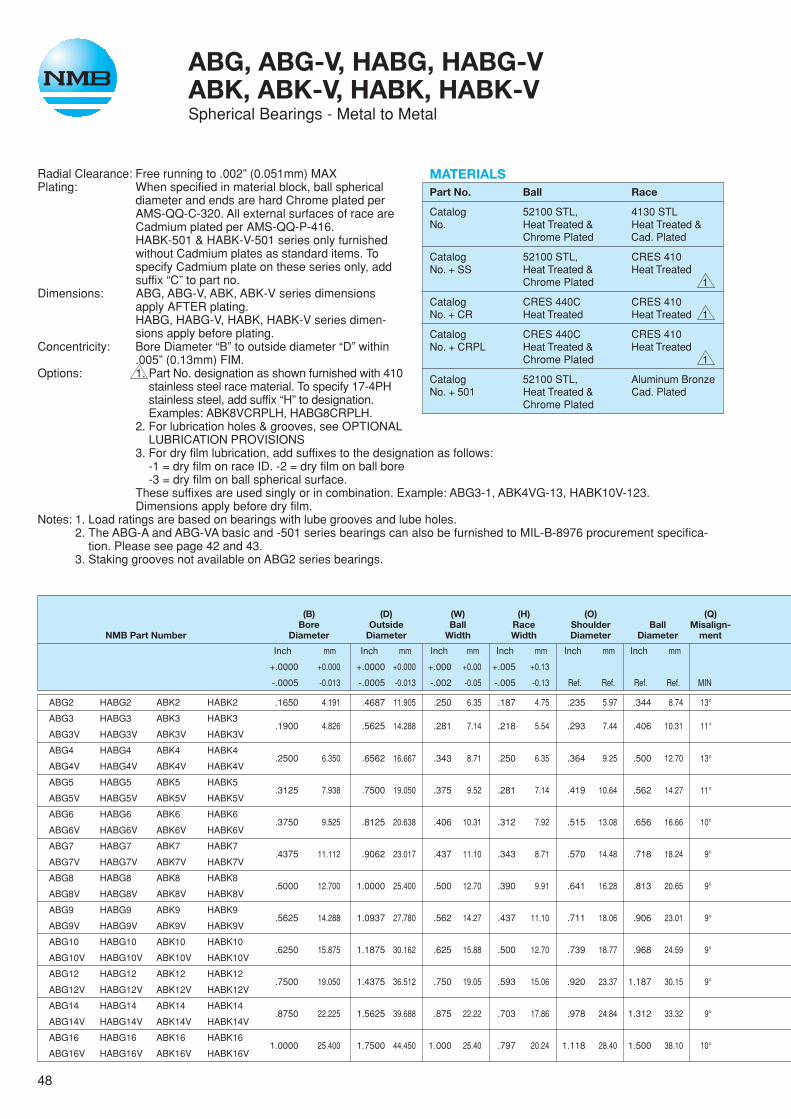
48
Radial Clearance: Free running to .002” (0.051mm) MAXPlating: When specified in material block, ball spherical
diameter and ends are hard Chrome plated perAMS-QQ-C-320. All external surfaces of race areCadmium plated per AMS-QQ-P-416.HABK-501 & HABK-V-501 series only furnishedwithout Cadmium plates as standard items. Tospecify Cadmium plate on these series only, addsuffix “C” to part no.
Dimensions: ABG, ABG-V, ABK, ABK-V series dimensionsapply AFTER plating.HABG, HABG-V, HABK, HABK-V series dimen-sions apply before plating.
Concentricity: Bore Diameter “B” to outside diameter “D” within.005” (0.13mm) FIM.
Options: 1. Part No. designation as shown furnished with 410stainless steel race material. To specify 17-4PHstainless steel, add suffix “H” to designation.Examples: ABK8VCRPLH, HABG8CRPLH.
2. For lubrication holes & grooves, see OPTIONALLUBRICATION PROVISIONS
3. For dry film lubrication, add suffixes to the designation as follows:-1 = dry film on race ID. -2 = dry film on ball bore-3 = dry film on ball spherical surface.
These suffixes are used singly or in combination. Example: ABG3-1, ABK4VG-13, HABK10V-123.Dimensions apply before dry film.
Notes: 1. Load ratings are based on bearings with lube grooves and lube holes.2. The ABG-A and ABG-VA basic and -501 series bearings can also be furnished to MIL-B-8976 procurement specifica-
tion. Please see page 42 and 43.3. Staking grooves not available on ABG2 series bearings.
MATERIALSPart No. Ball Race
Catalog 52100 STL, 4130 STLNo. Heat Treated & Heat Treated &
Chrome Plated Cad. Plated
Catalog 52100 STL, CRES 410No. + SS Heat Treated & Heat Treated
Chrome Plated
Catalog CRES 440C CRES 410No. + CR Heat Treated Heat Treated
Catalog CRES 440C CRES 410No. + CRPL Heat Treated & Heat Treated
Chrome Plated
Catalog 52100 STL, Aluminum BronzeNo. + 501 Heat Treated & Cad. Plated
Chrome Plated
ABG, ABG-V, HABG, HABG-VABK, ABK-V, HABK, HABK-VSpherical Bearings - Metal to Metal
1
1
1
(B) (D) (W) (H) (O) (Q)Bore Outside Ball Race Shoulder Ball Misalign-
NMB Part Number Diameter Diameter Width Width Diameter Diameter ment
Inch mm Inch mm Inch mm Inch mm Inch mm Inch mm
+.0000 +0.000 +.0000 +0.000 +.000 +0.00 +.005 +0.13
-.0005 -0.013 -.0005 -0.013 -.002 -0.05 -.005 -0.13 MIN
ABG2 HABG2 ABK2 HABK2 .1650 4.191 .4687 11.905 .250 6.35 .187 4.75 .235 5.97 .344 8.74 13°
ABG3 HABG3 ABK3 HABK3.1900 4.826 .5625 14.288 .281 7.14 .218 5.54 .293 7.44 .406 10.31 11°
ABG3V HABG3V ABK3V HABK3V
ABG4 HABG4 ABK4 HABK4.2500 6.350 .6562 16.667 .343 8.71 .250 6.35 .364 9.25 .500 12.70 13°
ABG4V HABG4V ABK4V HABK4V
ABG5 HABG5 ABK5 HABK5.3125 7.938 .7500 19.050 .375 9.52 .281 7.14 .419 10.64 .562 14.27 11°
ABG5V HABG5V ABK5V HABK5V
ABG6 HABG6 ABK6 HABK6.3750 9.525 .8125 20.638 .406 10.31 .312 7.92 .515 13.08 .656 16.66 10°
ABG6V HABG6V ABK6V HABK6V
ABG7 HABG7 ABK7 HABK7.4375 11.112 .9062 23.017 .437 11.10 .343 8.71 .570 14.48 .718 18.24 9°
ABG7V HABG7V ABK7V HABK7V
ABG8 HABG8 ABK8 HABK8.5000 12.700 1.0000 25.400 .500 12.70 .390 9.91 .641 16.28 .813 20.65 9°
ABG8V HABG8V ABK8V HABK8V
ABG9 HABG9 ABK9 HABK9.5625 14.288 1.0937 27.780 .562 14.27 .437 11.10 .711 18.06 .906 23.01 9°
ABG9V HABG9V ABK9V HABK9V
ABG10 HABG10 ABK10 HABK10.6250 15.875 1.1875 30.162 .625 15.88 .500 12.70 .739 18.77 .968 24.59 9°
ABG10V HABG10V ABK10V HABK10V
ABG12 HABG12 ABK12 HABK12.7500 19.050 1.4375 36.512 .750 19.05 .593 15.06 .920 23.37 1.187 30.15 9°
ABG12V HABG12V ABK12V HABK12V
ABG14 HABG14 ABK14 HABK14.8750 22.225 1.5625 39.688 .875 22.22 .703 17.86 .978 24.84 1.312 33.32 9°
ABG14V HABG14V ABK14V HABK14V
ABG16 HABG16 ABK16 HABK161.0000 25.400 1.7500 44.450 1.000 25.40 .797 20.24 1.118 28.40 1.500 38.10 10°
ABG16V HABG16V ABK16V HABK16V
Ref. Ref. Ref. Ref.
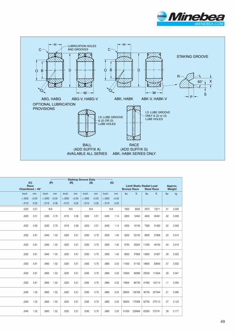
49
H
W
STAKING GROOVE
ABG, HABG
OPTIONAL LUBRICATION PROVISIONS
ABG-V, HABG-V ABK, HABK ABK-V, HABK-V
DO
Q
B
LUBRICATION HOLESAND GROOVES
HCC
W
DO
Q
B
I.D. LUBE GROOVE& (2) OR (3)LUBE HOLES
I.D. LUBE GROOVEONLY & (2) or (3)LUBE HOLES
BALL(ADD SUFFIX A)
AVAILABLE ALL SERIES
RACE(ADD SUFFIX G)
ABK, HABK SERIES ONLY
SP
R
60° X
Staking Groove Data(C) (P) (R) (S) (X)
Race Limit Static Radial Load Approx.Chamfered ✕ 45° Bronze Race Steel Race Weight
Inch mm Inch mm Inch mm Inch mm Inch mm lbs N lbs N lbs kg
+.000 +0.00 +.000 +0.00 +.000 +0.00 +.000 +0.00 +.000 +0.00
-.010 -0.25 -.015 -0.38 -.010 -0.25 -.010 -0.25 -.010 -0.25
.020 0.51 N/A N/A N/A N/A 1800 8006 2970 13211 .01 0.005
.020 0.51 .030 0.76 .015 0.38 .020 0.51 .045 1.14 2800 12454 4600 20461 .02 0.009
.022 0.56 .030 0.76 .015 0.38 .020 0.51 .045 1.14 4300 19126 7080 31492 .02 0.009
.032 0.81 .040 1.02 .020 0.51 .030 0.76 .055 1.40 5200 23130 8500 37808 .03 0.014
.032 0.81 .040 1.02 .020 0.51 .030 0.76 .055 1.40 6750 30024 11050 49150 .04 0.019
.032 0.81 .040 1.02 .020 0.51 .030 0.76 .055 1.40 8500 37808 13900 61827 .05 0.023
.032 0.81 .060 1.52 .020 0.51 .030 0.76 .080 2.03 11500 51152 18850 83845 .07 0.032
.032 0.81 .060 1.52 .020 0.51 .030 0.76 .080 2.03 15600 69389 25500 113424 .09 0.041
.032 0.81 .060 1.52 .020 0.51 .030 0.76 .080 2.03 19500 86736 31950 142114 .11 0.050
.040 1.02 .060 1.52 .020 0.51 .030 0.76 .080 2.03 28500 126768 46750 207944 .21 0.096
.040 1.02 .060 1.52 .020 0.51 .030 0.76 .080 2.03 38300 170358 62750 279112 .27 0.123
.040 1.02 .060 1.52 .020 0.51 .030 0.76 .080 2.03 51000 226848 83350 370741 .39 0.177
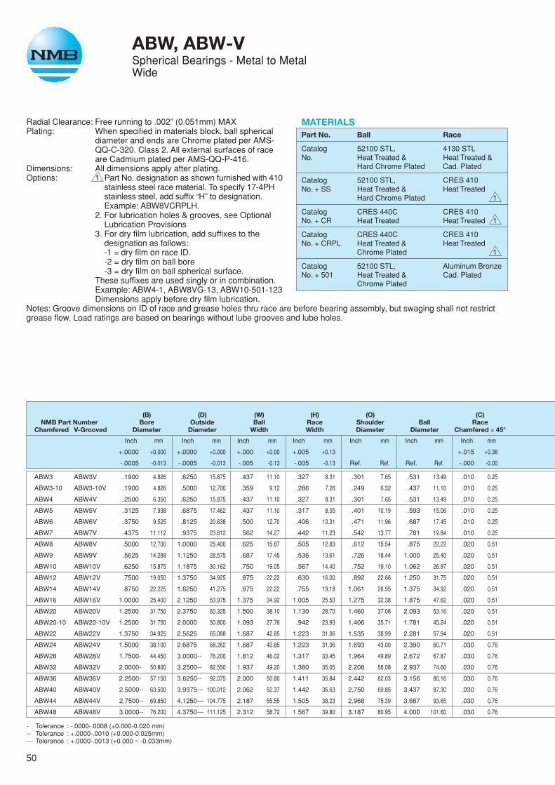
50
ABW, ABW-VSpherical Bearings - Metal to MetalWide
Radial Clearance: Free running to .002” (0.051mm) MAXPlating: When specified in materials block, ball spherical
diameter and ends are Chrome plated per AMS-QQ-C-320. Class 2. All external surfaces of raceare Cadmium plated per AMS-QQ-P-416.
Dimensions: All dimensions apply after plating.Options: 1. Part No. designation as shown furnished with 410
stainless steel race material. To specify 17-4PHstainless steel, add suffix “H” to designation.Example: ABW8VCRPLH.
2. For lubrication holes & grooves, see OptionalLubrication Provisions
3. For dry film lubrication, add suffixes to thedesignation as follows:-1 = dry film on race ID.-2 = dry film on ball bore-3 = dry film on ball spherical surface.
These suffixes are used singly or in combination.Example: ABW4-1, ABW8VG-13, ABW10-501-123Dimensions apply before dry film lubrication.
Notes: Groove dimensions on ID of race and grease holes thru race are before bearing assembly, but swaging shall not restrictgrease flow. Load ratings are based on bearings without lube grooves and lube holes.
MATERIALSPart No. Ball Race
Catalog 52100 STL, 4130 STLNo. Heat Treated & Heat Treated &
Hard Chrome Plated Cad. Plated
Catalog 52100 STL, CRES 410No. + SS Heat Treated & Heat Treated
Hard Chrome Plated
Catalog CRES 440C CRES 410No. + CR Heat Treated Heat Treated
Catalog CRES 440C CRES 410No. + CRPL Heat Treated & Heat Treated
Chrome Plated
Catalog 52100 STL, Aluminum BronzeNo. + 501 Heat Treated & Cad. Plated
Chrome Plated
1
1
1
(B) (D) (W) (H) (O) (C)NMB Part Number Bore Outside Ball Race Shoulder Ball Race
Chamfered V-Grooved Diameter Diameter Width Width Diameter Diameter Chamfered ✕ 45°
Inch mm Inch mm Inch mm Inch mm Inch mm Inch mm Inch mm
+.0000 +0.000 +.0000 +0.000 +.000 +0.00 +.005 +0.13 +.015 +0.38
-.0005 -0.013 -.0005 -0.013 -.005 -0.13 -.005 -0.13 Ref. Ref. Ref. Ref. -.000 -0.00
ABW3 ABW3V .1900 4.826 .6250 15.875 .437 11.10 .327 8.31 .301 7.65 .531 13.49 .010 0.25
ABW3-10 ABW3-10V .1900 4.826 .5000 12.700 .359 9.12 .286 7.26 .249 6.32 .437 11.10 .010 0.25
ABW4 ABW4V .2500 6.350 .6250 15.875 .437 11.10 .327 8.31 .301 7.65 .531 13.49 .010 0.25
ABW5 ABW5V .3125 7.938 .6875 17.462 .437 11.10 .317 8.05 .401 10.19 .593 15.06 .010 0.25
ABW6 ABW6V .3750 9.525 .8125 20.638 .500 12.70 .406 10.31 .471 11.96 .687 17.45 .010 0.25
ABW7 ABW7V .4375 11.112 .9375 23.812 .562 14.27 .442 11.23 .542 13.77 .781 19.84 .010 0.25
ABW8 ABW8V .5000 12.700 1.0000 25.400 .625 15.87 .505 12.83 .612 15.54 .875 22.22 .020 0.51
ABW9 ABW9V .5625 14.288 1.1250 28.575 .687 17.45 .536 13.61 .726 18.44 1.000 25.40 .020 0.51
ABW10 ABW10V .6250 15.875 1.1875 30.162 .750 19.05 .567 14.40 .752 19.10 1.062 26.97 .020 0.51
ABW12 ABW12V .7500 19.050 1.3750 34.925 .875 22.22 .630 16.00 .892 22.66 1.250 31.75 .020 0.51
ABW14 ABW14V .8750 22.225 1.6250 41.275 .875 22.22 .755 19.18 1.061 26.95 1.375 34.92 .020 0.51
ABW16 ABW16V 1.0000 25.400 2.1250 53.975 1.375 34.92 1.005 25.53 1.275 32.38 1.875 47.62 .020 0.51
ABW20 ABW20V 1.2500 31.750 2.3750 60.325 1.500 38.10 1.130 28.70 1.460 37.08 2.093 53.16 .020 0.51
ABW20-10 ABW20-10V 1.2500 31.750 2.0000 50.800 1.093 27.76 .942 23.93 1.406 35.71 1.781 45.24 .020 0.51
ABW22 ABW22V 1.3750 34.925 2.5625 65.088 1.687 42.85 1.223 31.06 1.535 38.99 2.281 57.94 .020 0.51
ABW24 ABW24V 1.5000 38.100 2.6875 68.262 1.687 42.85 1.223 31.06 1.693 43.00 2.390 60.71 .030 0.76
ABW28 ABW28V 1.7500- 44.450 3.0000-- 76.200 1.812 46.02 1.317 33.45 1.964 49.89 2.672 67.87 .030 0.76
ABW32 ABW32V 2.0000- 50.800 3.2500-- 82.550 1.937 49.20 1.380 35.05 2.208 56.08 2.937 74.60 .030 0.76
ABW36 ABW36V 2.2500- 57.150 3.6250-- 92.075 2.000 50.80 1.411 35.84 2.442 62.03 3.156 80.16 .030 0.76
ABW40 ABW40V 2.5000-- 63.500 3.9375--- 100.012 2.062 52.37 1.442 36.63 2.750 69.85 3.437 87.30 .030 0.76
ABW44 ABW44V 2.7500-- 69.850 4.1250--- 104.775 2.187 55.55 1.505 38.23 2.968 75.39 3.687 93.65 .030 0.76
ABW48 ABW48V 3.0000-- 76.200 4.3750--- 111.125 2.312 58.72 1.567 39.80 3.187 80.95 4.000 101.60 .030 0.76
- Tolerance : -.0000-.0008 (+0.000-0.020 mm)-- Tolerance : +.0000-.0010 (+0.000-0.025mm)--- Tolerance : +.0000-.0013 (+0.000 ~ -0.033mm)
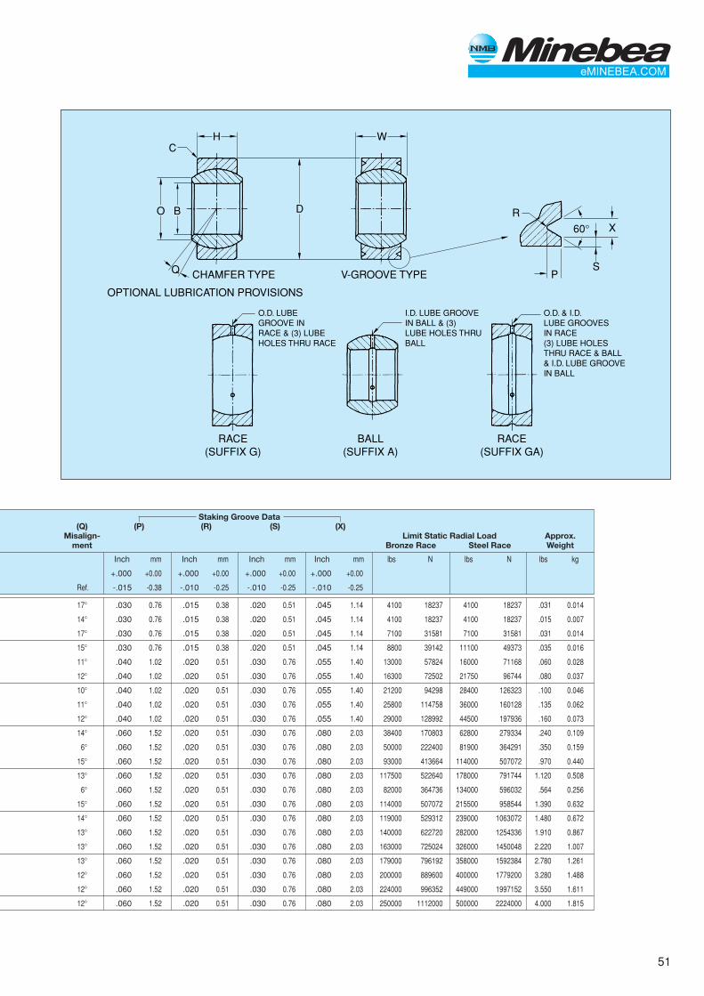
51
H W
CHAMFER TYPE
OPTIONAL LUBRICATION PROVISIONS
V-GROOVE TYPE
DO
Q
B
C
O.D. LUBEGROOVE INRACE & (3) LUBEHOLES THRU RACE
RACE(SUFFIX G)
BALL(SUFFIX A)
RACE(SUFFIX GA)
O.D. & I.D.LUBE GROOVESIN RACE(3) LUBE HOLESTHRU RACE & BALL& I.D. LUBE GROOVEIN BALL
I.D. LUBE GROOVEIN BALL & (3)LUBE HOLES THRUBALL
SP
R
60° X
Staking Groove Data(Q) (P) (R) (S) (X)
Misalign- Limit Static Radial Load Approx.ment Bronze Race Steel Race Weight
Inch mm Inch mm Inch mm Inch mm lbs N lbs N lbs kg
+.000 +0.00 +.000 +0.00 +.000 +0.00 +.000 +0.00
Ref. -.015 -0.38 -.010 -0.25 -.010 -0.25 -.010 -0.25
17° .030 0.76 .015 0.38 .020 0.51 .045 1.14 4100 18237 4100 18237 .031 0.014
14° .030 0.76 .015 0.38 .020 0.51 .045 1.14 4100 18237 4100 18237 .015 0.007
17° .030 0.76 .015 0.38 .020 0.51 .045 1.14 7100 31581 7100 31581 .031 0.014
15° .030 0.76 .015 0.38 .020 0.51 .045 1.14 8800 39142 11100 49373 .035 0.016
11° .040 1.02 .020 0.51 .030 0.76 .055 1.40 13000 57824 16000 71168 .060 0.028
12° .040 1.02 .020 0.51 .030 0.76 .055 1.40 16300 72502 21750 96744 .080 0.037
10° .040 1.02 .020 0.51 .030 0.76 .055 1.40 21200 94298 28400 126323 .100 0.046
11° .040 1.02 .020 0.51 .030 0.76 .055 1.40 25800 114758 36000 160128 .135 0.062
12° .040 1.02 .020 0.51 .030 0.76 .055 1.40 29000 128992 44500 197936 .160 0.073
14° .060 1.52 .020 0.51 .030 0.76 .080 2.03 38400 170803 62800 279334 .240 0.109
6° .060 1.52 .020 0.51 .030 0.76 .080 2.03 50000 222400 81900 364291 .350 0.159
15° .060 1.52 .020 0.51 .030 0.76 .080 2.03 93000 413664 114000 507072 .970 0.440
13° .060 1.52 .020 0.51 .030 0.76 .080 2.03 117500 522640 178000 791744 1.120 0.508
6° .060 1.52 .020 0.51 .030 0.76 .080 2.03 82000 364736 134000 596032 .564 0.256
15° .060 1.52 .020 0.51 .030 0.76 .080 2.03 114000 507072 215500 958544 1.390 0.632
14° .060 1.52 .020 0.51 .030 0.76 .080 2.03 119000 529312 239000 1063072 1.480 0.672
13° .060 1.52 .020 0.51 .030 0.76 .080 2.03 140000 622720 282000 1254336 1.910 0.867
13° .060 1.52 .020 0.51 .030 0.76 .080 2.03 163000 725024 326000 1450048 2.220 1.007
13° .060 1.52 .020 0.51 .030 0.76 .080 2.03 179000 796192 358000 1592384 2.780 1.261
12° .060 1.52 .020 0.51 .030 0.76 .080 2.03 200000 889600 400000 1779200 3.280 1.488
12° .060 1.52 .020 0.51 .030 0.76 .080 2.03 224000 996352 449000 1997152 3.550 1.611
12° .060 1.52 .020 0.51 .030 0.76 .080 2.03 250000 1112000 500000 2224000 4.000 1.815
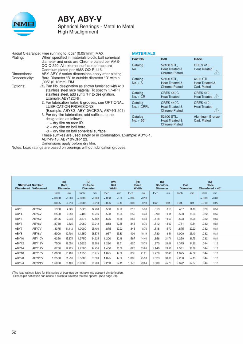
52
ABY, ABY-VSpherical Bearings - Metal to MetalHigh Misalignment
Radial Clearance: Free running to .002” (0.051mm) MAXPlating: When specified in materials block, ball spherical
diameter and ends are Chrome plated per AMS-QQ-C-320. All external surfaces of race areCadmium plated per AMS-QQ-P-416.
Dimensions: ABY, ABY-V series dimensions apply after plating.Concentricity: Bore Diameter “B” to outside diameter “D” within
.005” (0.13mm) FIM.Options: 1. Part No. designation as shown furnished with 410
stainless steel race material. To specify 17-4PHstainless steel, add suffix “H” to designation.Example: ABY12CRH.
2. For lubrication holes & grooves, see OPTIONALLUBRICATION PROVISIONS(Example: ABY8G, ABY10VCRGA, ABY4G-501)
3. For dry film lubrication, add suffixes to thedesignation as follows:-1 = dry film on race ID.-2 = dry film on ball bore-3 = dry film on ball spherical surface.
These suffixes are used singly or in combination. Example: ABY8-1,ABY4V-13, ABY10VCR-123.Dimensions apply before dry film.
Notes: Load ratings are based on bearings without lubrication grooves.
MATERIALSPart No. Ball Race
Catalog 52100 STL, CRES 410No. Heat Treated & Heat Treated
Chrome Plated
Catalog 52100 STL, 4130 STLNo. + S Heat Treated & Heat Treated &
Chrome Plated Cad. Plated
Catalog CRES 440C CRES 410No. + CR Heat Treated Heat Treated
Catalog CRES 440C CRES 410No. + CRPL Heat Treated & Heat Treated
Chrome Plated
Catalog 52100 STL, Aluminum BronzeNo. + 501 Heat Treated & Cad. Plated
Chrome Plated
1
1
1
(B) (D) (W) (H) (O) (C)NMB Part Number Bore Outside Ball Race Shoulder Ball Race
Chamfered V-Grooved Diameter Diameter Width Width Diameter Diameter Chamfered ✕ 45°
Inch mm Inch mm Inch mm Inch mm Inch mm Inch mm Inch mm
+.0000 +0.000 +.0000 +0.000 +.000 +0.00 +.005 +0.13 +.000 +0.00
-.0005 -0.013 -.0005 -0.013 -.005 -0.13 -.005 -0.13 Ref. Ref. Ref. Ref. -.010 -0.25
ABY3 ABY3V .1900 4.826 .5625 14.288 .500 12.70 .210 5.33 .319 8.10 .437 11.10 .020 0.51
ABY4 ABY4V .2500 6.350 .7400 18.796 .593 15.06 .255 6.48 .390 9.91 .593 15.06 .022 0.56
ABY5 ABY5V .3125 7.938 .6875 17.462 .625 15.88 .255 6.48 .418 10.62 .593 15.06 .022 0.56
ABY6 ABY6V .3750 9.525 .9060 23.012 .813 20.65 .345 8.76 .512 13.00 .781 19.84 .032 0.81
ABY7 ABY7V .4375 11.112 1.0000 25.400 .875 22.22 .345 8.76 .618 15.70 .875 22.22 .032 0.81
ABY8 ABY8V .5000 12.700 1.1250 28.575 .937 23.80 .401 10.19 .730 18.54 1.000 25.40 .032 0.81
ABY10 ABY10V .6250 15.875 1.3750 34.925 1.200 30.48 .567 14.40 .856 21.74 1.250 31.75 .032 0.81
ABY12 ABY12V .7500 19.050 1.5625 39.688 1.280 32.51 .620 15.75 .970 24.64 1.375 34.92 .044 1.12
ABY14 ABY14V .8750 22.225 1.7500 44.450 1.400 35.56 .625 15.88 1.140 28.96 1.531 38.89 .044 1.12
ABY16 ABY16V 1.0000 25.400 2.1250 53.975 1.875 47.62 .835 21.21 1.278 32.46 1.875 47.62 .044 1.12
ABY20 ABY20V 1.2500 31.750 2.5000 63.500 1.875 47.62 1.005 25.53 1.523 38.68 2.250 57.15 .044 1.12
ABY24 ABY24V 1.5000 38.100 3.0000 76.200 2.250 57.15 1.175 29.84 1.800 45.72 2.672 67.87 .044 1.12
#The load ratings listed for this series of bearings do not take into account pin deflection.Excess pin deflection can cause a crack to traverse the ball sphere. (See page 24).

53
H W
CHAMFER TYPE
OPTIONAL LUBRICATION PROVISIONS
V-GROOVE TYPE
STAKING GROOVE
DO
Q
B
C
BALL(ADD SUFFIX A)
RACE(ADD SUFFIX G)
I.D. LUBE GROOVEONLY & (2) OR (3)LUBE HOLES
II.D. LUBEGROOVE& (2) OR (3)LUBE HOLES
SP
R60° X
.005 (0.13mm)
.015 (0.38mm)45°CHAMFER
✕
Staking Groove Data(Q) (P) (R) (S) (X)
Misalign- Limit Static Radial Load Approx.ment Bronze Race Steel Race Weight
Inch mm Inch mm Inch mm Inch mm lbs N lbs N lbs kg
+.000 +0.00 +.000 +0.00 +.000 +0.00 +.000 +0.00
Ref. -.015 -0.38 -.010 -0.25 -.010 -0.25 -.010 -0.25
15° .030 0.76 .015 0.38 .020 0.51 .045 1.14 4000 17792 4100 18237 .018 0.009
24° .030 0.76 .015 0.38 .020 0.51 .045 1.14 6800 30246 7100 31581 .036 0.017
20° .030 0.76 .015 0.38 .020 0.51 .045 1.14 6800 30246 9000 40032 .025 0.012
23° .030 0.76 .015 0.38 .020 0.51 .045 1.14 12700 56490 16000 71168 .068 0.031
22° .030 0.76 .015 0.38 .020 0.51 .045 1.14 14300 63606 21800 96966 .095 0.043
20° .030 0.76 .015 0.38 .020 0.51 .045 1.14 18700 83178 28500 126768 .159 0.073
20° .040 1.02 .020 0.51 .030 0.76 .055 1.40 34400 153011 44500 197936 .245 0.112
18° .060 1.52 .020 0.51 .030 0.76 .080 2.03 41500 184592 64000 284672 .315 0.143
18° .060 1.52 .020 0.51 .030 0.76 .080 2.03 44800 199270 76700 341162 .430 0.195
21° .060 1.52 .020 0.51 .030 0.76 .080 2.03 76000 338048 114000 507072 .831 0.377
21° .060 1.52 .020 0.51 .030 0.76 .080 2.03 111500 495952 178000 791744 1.318 0.598
21° .060 1.52 .020 0.51 .030 0.76 .080 2.03 128000 569344 256000 1138688 2.223 1.009
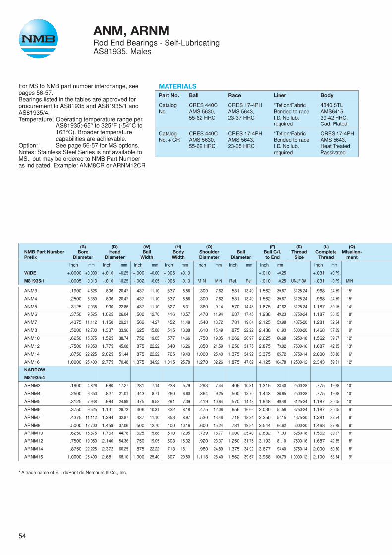
54
For MS to NMB part number interchange, seepages 56-57.Bearings listed in the tables are approved forprocurement to AS81935 and AS81935/1 andAS81935/4.Temperature: Operating temperature range per
AS81935;-65° to 325°F (-54°C to163°C). Broader temperaturecapabilities are achievable.
Option: See page 56-57 for MS options.Notes: Stainless Steel Series is not available toMS., but may be ordered to NMB Part Numberas indicated. Example: ANM8CR or ARNM12CR
ANM, ARNMRod End Bearings - Self-LubricatingAS81935, Males
MATERIALSPart No. Ball Race Liner Body
Catalog CRES 440C CRES 17-4PH *Teflon/Fabric 4340 STLNo. AMS 5630, AMS 5643, Bonded to race AMS6415
55-62 HRC 23-37 HRC I.D. No lub. 39-42 HRC,required Cad. Plated
Catalog CRES 440C CRES 17-4PH *Teflon/Fabric CRES 17-4PHNo. + CR AMS 5630, AMS 5643, Bonded to race AMS 5643,
55-62 HRC 23-35 HRC I.D. No lub. Heat Treatedrequired Passivated
(B) (D) (W) (H) (O) (F) (E) (L) (Q)NMB Part Number Bore Head Ball Body Shoulder Ball Ball C/L Thread Complete Misalign-Prefix Diameter Diameter Width Width Diameter Diameter to End Size Thread ment
Inch mm Inch mm Inch mm Inch mm Inch mm Inch mm Inch mm Inch mm
WIDE +.0000 +0.000 +.010 +0.25 +.000 +0.00 +.005 +0.13 +.010 +0.25 +.031 +0.79
M81935/1 -.0005 -0.013 -.010 -0.25 -.002 -0.05 -.005 -0.13 MIN MIN Ref. Ref. -.010 -0.25 UNJF-3A -.031 -0.79 MIN
ANM3 .1900 4.826 .806 20.47 .437 11.10 .337 8.56 .300 7.62 .531 13.49 1.562 39.67 .3125-24 .968 24.59 15°
ANM4 .2500 6.350 .806 20.47 .437 11.10 .337 8.56 .300 7.62 .531 13.49 1.562 39.67 .3125-24 .968 24.59 15°
ANM5 .3125 7.938 .900 22.86 .437 11.10 .327 8.31 .360 9.14 .570 14.48 1.875 47.62 .3125-24 1.187 30.15 14°
ANM6 .3750 9.525 1.025 26.04 .500 12.70 .416 10.57 .470 11.94 .687 17.45 1.938 49.23 .3750-24 1.187 30.15 8°
ANM7 .4375 11.112 1.150 29.21 .562 14.27 .452 11.48 .540 13.72 .781 19.84 2.125 53.98 .4375-20 1.281 32.54 10°
ANM8 .5000 12.700 1.337 33.96 .625 15.88 .515 13.08 .610 15.49 .875 22.22 2.438 61.93 .5000-20 1.468 37.29 9°
ANM10 .6250 15.875 1.525 38.74 .750 19.05 .577 14.66 .750 19.05 1.062 26.97 2.625 66.68 .6250-18 1.562 39.67 12°
ANM12 .7500 19.050 1.775 45.08 .875 22.22 .640 16.26 .850 21.59 1.250 31.75 2.875 73.02 .7500-16 1.687 42.85 13°
ANM14 .8750 22.225 2.025 51.44 .875 22.22 .765 19.43 1.000 25.40 1.375 34.92 3.375 85.72 .8750-14 2.000 50.80 6°
ANM16 1.0000 25.400 2.775 70.48 1.375 34.92 1.015 25.78 1.270 32.26 1.875 47.62 4.125 104.78 1.2500-12 2.343 59.51 12°
NARROW
M81935/4
ARNM3 .1900 4.826 .680 17.27 .281 7.14 .228 5.79 .293 7.44 .406 10.31 1.315 33.40 .2500-28 .775 19.68 10°
ARNM4 .2500 6.350 .827 21.01 .343 8.71 .260 6.60 .364 9.25 .500 12.70 1.443 36.65 .2500-28 .775 19.68 10°
ARNM5 .3125 7.938 .984 24.99 .375 9.52 .291 7.39 .419 10.64 .570 14.48 1.948 49.48 .3125-24 1.187 30.15 10°
ARNM6 .3750 9.525 1.131 28.73 .406 10.31 .322 8.18 .475 12.06 .656 16.66 2.030 51.56 .3750-24 1.187 30.15 9°
ARNM7 .4375 11.112 1.294 32.87 .437 11.10 .353 8.97 .530 13.46 .718 18.24 2.250 57.15 .4375-20 1.281 32.54 8°
ARNM8 .5000 12.700 1.459 37.06 .500 12.70 .400 10.16 .600 15.24 .781 19.84 2.544 64.62 .5000-20 1.468 37.29 8°
ARNM10 .6250 15.875 1.763 44.78 .625 15.88 .510 12.95 .739 18.77 1.000 25.40 2.832 71.93 .6250-18 1.562 39.67 8°
ARNM12 .7500 19.050 2.140 54.36 .750 19.05 .603 15.32 .920 23.37 1.250 31.75 3.193 81.10 .7500-16 1.687 42.85 8°
ARNM14 .8750 22.225 2.372 60.25 .875 22.22 .713 18.11 .980 24.89 1.375 34.92 3.677 93.40 .8750-14 2.000 50.80 8°
ARNM16 1.0000 25.400 2.681 68.10 1.000 25.40 .807 20.50 1.118 28.40 1.562 39.67 3.968 100.79 1.0000-12 2.100 53.34 9°
* A trade name of E.I. duPont de Nemours & Co., Inc.
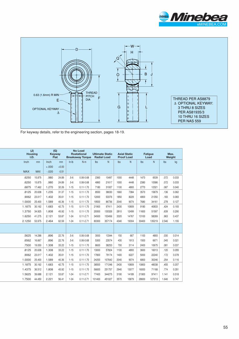
55
DW
H
F
Q
LG
O JB
THREAD PER AS8879 OPTIONAL KEYWAY: 3 THRU 8 SIZES PER AS81935/3 10 THRU 16 SIZES PER NAS 559
∆
∆
0.63 (1.6mm) R MIN
OPTIONAL KEYWAY
E
THREADPITCHDIA
For keyway details, refer to the engineering section, pages 18-19.
(J) (G) No LoadHousing Keyway Roatational Ultimate Static Axial Static Fatigue Max.
I.D. Flat Breakaway Torque Radial Load Proof Load Load Weight
Inch mm Inch mm In-lb N-m lbs N lbs N lbs N lbs kg
+.000 +0.00
MAX MAX -.020 -0.51
.6250 15.875 .980 24.89 .5-6 0.06-0.68 2360 10497 1000 4448 1470 6539 .072 0.033
.6250 15.875 .980 24.89 .5-6 0.06-0.68 4860 21617 1000 4448 2380 10586 .072 0.033
.6875 17.462 1.270 32.26 1-15 0.11-1.70 7180 31937 1100 4893 2770 12321 .087 0.040
.8125 20.638 1.235 31.37 1-15 0.11-1.70 8550 38030 1660 7384 3570 15879 .136 0.062
.9062 23.017 1.402 35.61 1-15 0.11-1.70 12000 53376 1850 8229 4800 21350 .183 0.083
1.0000 25.400 1.589 40.36 1-15 0.11-1.70 19500 86736 2040 9074 7680 34161 .278 0.127
1.1875 30.162 1.683 42.75 1-15 0.11-1.70 21900 97411 2430 10809 9180 40833 .424 0.193
1.3750 34.925 1.808 45.92 1-15 0.11-1.70 29300 130326 2810 12499 11600 51597 .639 0.290
1.6250 41.275 2.121 53.87 1-24 0.11-2.71 34500 153456 3320 14767 13100 58269 .963 0.437
2.1250 53.975 2.464 62.59 1-24 0.11-2.71 80300 357174 4340 19304 30400 135219 2.546 1.155
.5625 14.288 .896 22.76 .5-6 0.06-0.68 3000 13344 150 667 1100 4893 .030 0.014
.6562 16.667 .896 22.76 .5-6 0.06-0.68 5300 23574 430 1913 1500 6671 .045 0.021
.7500 19.050 1.308 33.22 1-15 0.11-1.70 8600 38253 700 3114 2400 10675 .081 0.037
.8125 20.638 1.308 33.22 1-15 0.11-1.70 13000 57824 1100 4893 3600 16013 .120 0.055
.9062 23.017 1.402 35.61 1-15 0.11-1.70 17800 79174 1400 6227 5000 22240 .172 0.078
1.0000 25.400 1.589 40.36 1-15 0.11-1.70 24200 107642 2040 9074 6800 30246 .254 0.116
1.1875 30.162 1.683 42.75 1-15 0.11-1.70 38500 171248 2430 10809 10800 48038 .455 0.207
1.4375 36.512 1.808 45.92 1-15 0.11-1.70 56600 251757 2940 13077 16000 71168 .774 0.351
1.5625 39.688 2.121 53.87 1-24 0.11-2.71 77400 344275 3190 14189 21900 97411 1.141 0.518
1.7500 44.450 2.221 56.41 1-24 0.11-2.71 101400 451027 3570 15879 28600 127213 1.646 0.747
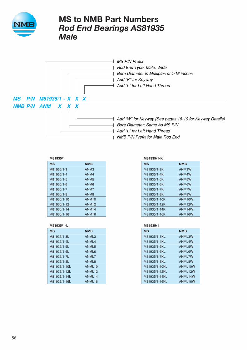
56
MS to NMB Part NumbersRod End Bearings AS81935Male
MS P/N PrefixRod End Type: Male, WideBore Diameter in Multiples of 1/16 inchesAdd “K” for KeywayAdd “L” for Left Hand Thread
Add “W” for Keyway (See pages 18-19 for Keyway Details)Bore Diameter: Same As MS P/NAdd “L” for Left Hand ThreadNMB P/N Prefix for Male Rod End
MS P/N M81935/1 - X X XNMB P/N ANM X X X
M81935/1
MS NMB
M81935/1-3KL ANML3W
M81935/1-4KL ANML4W
M81935/1-5KL ANML5W
M81935/1-6KL ANML6W
M81935/1-7KL ANML7W
M81935/1-8KL ANML8W
M81935/1-10KL ANML10W
M81935/1-12KL ANML12W
M81935/1-14KL ANML14W
M81935/1-16KL ANML16W
M81935/1-L
MS NMB
M81935/1-3L ANML3
M81935/1-4L ANML4
M81935/1-5L ANML5
M81935/1-6L ANML6
M81935/1-7L ANML7
M81935/1-8L ANML8
M81935/1-10L ANML10
M81935/1-12L ANML12
M81935/1-14L ANML14
M81935/1-16L ANML16
M81935/1
MS NMB
M81935/1-3 ANM3
M81935/1-4 ANM4
M81935/1-5 ANM5
M81935/1-6 ANM6
M81935/1-7 ANM7
M81935/1-8 ANM8
M81935/1-10 ANM10
M81935/1-12 ANM12
M81935/1-14 ANM14
M81935/1-16 ANM16
M81935/1-K
MS NMB
M81935/1-3K ANM3W
M81935/1-4K ANM4W
M81935/1-5K ANM5W
M81935/1-6K ANM6W
M81935/1-7K ANM7W
M81935/1-8K ANM8W
M81935/1-10K ANM10W
M81935/1-12K ANM12W
M81935/1-14K ANM14W
M81935/1-16K ANM16W
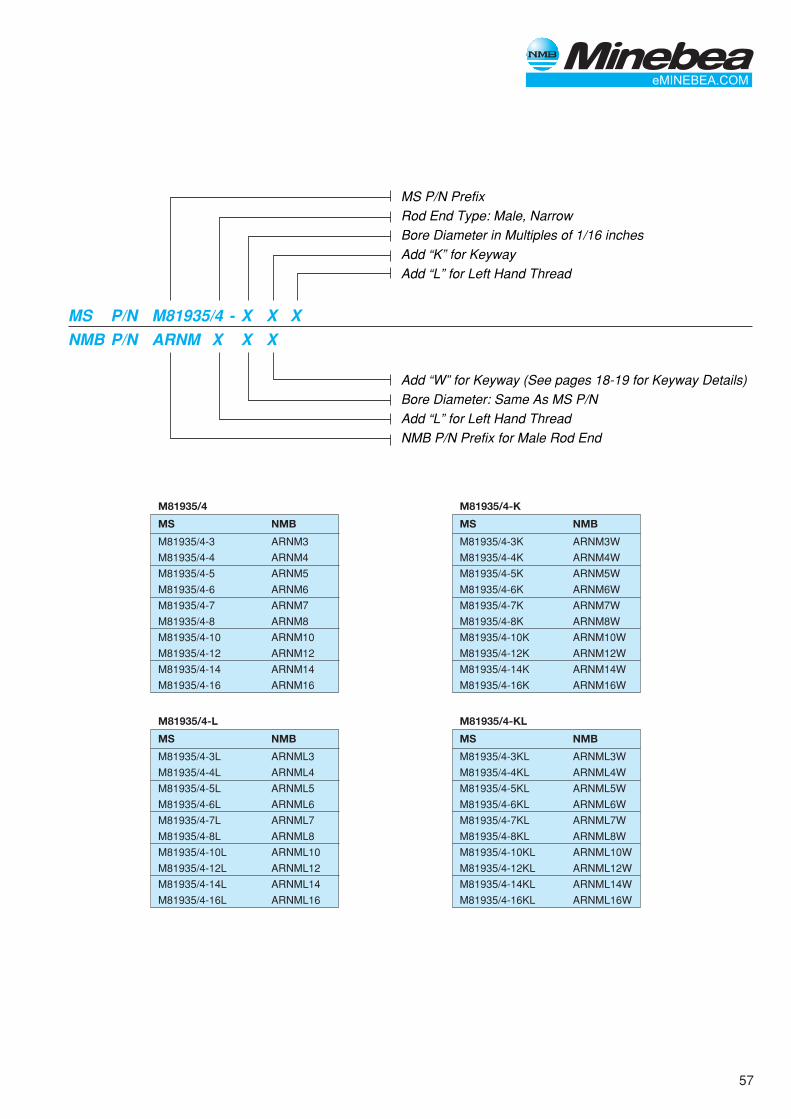
57
MS P/N PrefixRod End Type: Male, NarrowBore Diameter in Multiples of 1/16 inchesAdd “K” for KeywayAdd “L” for Left Hand Thread
Add “W” for Keyway (See pages 18-19 for Keyway Details)Bore Diameter: Same As MS P/NAdd “L” for Left Hand ThreadNMB P/N Prefix for Male Rod End
MS P/N M81935/4 - X X XNMB P/N ARNM X X X
M81935/4-L
MS NMB
M81935/4-3L ARNML3
M81935/4-4L ARNML4
M81935/4-5L ARNML5
M81935/4-6L ARNML6
M81935/4-7L ARNML7
M81935/4-8L ARNML8
M81935/4-10L ARNML10
M81935/4-12L ARNML12
M81935/4-14L ARNML14
M81935/4-16L ARNML16
M81935/4-KL
MS NMB
M81935/4-3KL ARNML3W
M81935/4-4KL ARNML4W
M81935/4-5KL ARNML5W
M81935/4-6KL ARNML6W
M81935/4-7KL ARNML7W
M81935/4-8KL ARNML8W
M81935/4-10KL ARNML10W
M81935/4-12KL ARNML12W
M81935/4-14KL ARNML14W
M81935/4-16KL ARNML16W
M81935/4-K
MS NMB
M81935/4-3K ARNM3W
M81935/4-4K ARNM4W
M81935/4-5K ARNM5W
M81935/4-6K ARNM6W
M81935/4-7K ARNM7W
M81935/4-8K ARNM8W
M81935/4-10K ARNM10W
M81935/4-12K ARNM12W
M81935/4-14K ARNM14W
M81935/4-16K ARNM16W
M81935/4
MS NMB
M81935/4-3 ARNM3
M81935/4-4 ARNM4
M81935/4-5 ARNM5
M81935/4-6 ARNM6
M81935/4-7 ARNM7
M81935/4-8 ARNM8
M81935/4-10 ARNM10
M81935/4-12 ARNM12
M81935/4-14 ARNM14
M81935/4-16 ARNM16
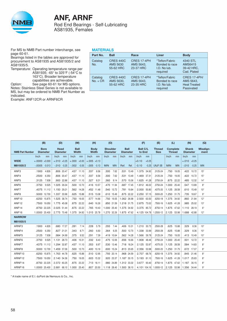
58
For MS to NMB Part number interchange, seepage 60-61.Bearings listed in the tables are approved forprocurement to AS81935 and AS81935/2 andAS81935/5.Temperature: Operating temperature range per
AS81935; -65° to 325°F (-54°C to163°C). Broader temperaturecapabilities are achievable.
Option: See page 60-61 for MS options.Notes: Stainless Steel Series is not available toMS, but may be ordered to NMB Part Number asindicated.Example: ANF12CR or ARNF6CR
ANF, ARNFRod End Bearings - Self-LubricatingAS81935, Females
MATERIALSPart No. Ball Race Liner Body
Catalog CRES 440C CRES 17-4PH *Teflon/Fabric 4340 STLNo. AMS 5630 AMS 5643, Bonded to race AMS6415
55-62 HRC 23-37 HRC I.D. No lub. 39-42 HRC,required Cad. Plated
Catalog CRES 440C CRES 17-4PH *Teflon/Fabric CRES 17-4PH/No. + CR AMS 5630, AMS 5643, Bonded to race AMS 5643,
55-62 HRC 23-35 HRC I.D. No lub. Heat Treatedrequired Passivated
(B) (D) (W) (H) (O) (F) (E) (L) (N) (Q)
Bore Head Ball Body Shoulder Ball Ball C/L Thread Complete Shank Misalign-NMB Part Number Diameter Diameter Width Width Diameter Diameter to End Size Thread Diameter ment
Inch mm Inch mm Inch mm Inch mm Inch mm Inch mm Inch mm Inch mm Inch mm
WIDE +.0000 +0.000 +.010 +0.25 +.000 +0.00 +.005 +0.13 +0.10 +0.25 +.010 +0.25
M81935/2 -.0005 -0.013 -.010 -0.25 -.002 -0.05 -.005 -0.13 MIN MIN Ref. Ref. -0.10 -0.25 UNJF-3B MIN MIN -.010 -0.25 MIN
ANF3 .1900 4.826 .806 20.47 .437 11.10 .337 8.56 .300 7.62 .531 13.49 1.375 34.92 .3125-24 .750 19.05 .422 10.72 15°
ANF4 .2500 6.350 .806 20.47 .437 11.10 .337 8.56 .300 7.62 .531 13.49 1.469 37.31 .3125-24 .750 19.05 .422 10.72 15°
ANF5 .3125 7.938 .900 22.86 .437 11.10 .327 8.31 .360 9.14 .570 15.06 1.625 41.28 .3750-24 .875 22.22 .485 12.32 14°
ANF6 .3750 9.525 1.025 26.04 .500 12.70 .416 10.57 .470 11.94 .687 17.45 1.812 46.02 .3750-24 1.000 25.40 .547 13.89 8°
ANF7 .4375 11.112 1.150 29.21 .562 14.28 .452 11.48 .540 13.72 .781 19.84 2.000 50.80 .4375-20 1.125 28.58 .610 15.49 10°
ANF8 .5000 12.700 1.337 33.96 .625 15.88 .515 13.08 .610 15.49 .875 22.22 2.250 57.15 .5000-20 1.250 31.75 .735 18.67 9°
ANF10 .6250 15.875 1.525 38.74 .750 19.05 .577 14.66 .750 19.05 1.062 26.98 2.500 63.50 .6250-18 1.375 34.92 .860 21.84 12°
ANF12 .7500 19.050 1.775 45.08 .875 22.22 .640 16.26 .850 21.59 1.218 31.75 2.875 73.02 .7500-16 1.625 41.28 .985 25.02 13°
ANF14 .8750 22.225 2.025 51.44 .875 22.22 .765 19.43 1.000 25.40 1.375 34.92 3.375 85.72 .8750-14 1.875 47.62 1.110 28.19 6°
ANF16 1.0000 25.400 2.775 70.48 1.375 34.92 1.015 25.78 1.270 32.26 1.875 47.62 4.125 104.78 1.2500-12 2.125 53.98 1.688 42.88 12°
NARROW
M81935/5
ARNF3 .1900 4.826 .680 17.27 .281 7.14 .228 5.79 .293 7.44 .406 10.31 1.210 30.73 .2500-28 .625 15.88 .329 8.36 10°
ARNF4 .2500 6.350 .827 21.01 .343 8.71 .260 6.60 .364 9.25 .500 12.70 1.338 33.99 .2500-28 .625 15.88 .329 8.36 10°
ARNF5 .3125 7.938 .984 24.99 .375 9.52 .291 7.39 .419 10.64 .562 14.28 1.566 39.78 .3125-24 .750 19.05 .413 10.49 10°
ARNF6 .3750 9.525 1.131 28.73 .406 10.31 .332 8.43 .475 12.06 .656 16.66 1.908 48.46 .3750-24 1.000 25.40 .501 12.72 9°
ARNF7 .4375 11.112 1.294 32.87 .437 11.10 .353 8.97 .530 13.46 .718 18.24 2.125 53.97 .4375-20 1.125 28.58 .584 14.83 8°
ARNF8 .5000 12.700 1.459 37.06 .500 12.70 .400 10.16 .600 15.24 .813 20.65 2.356 53.98 .5000-20 1.250 31.75 .672 17.07 8°
ARNF10 .6250 15.875 1.763 44.78 .625 15.88 .510 12.95 .793 20.14 .968 24.59 2.707 68.76 .6250-18 1.375 34.92 .845 21.46 8°
ARNF12 .7500 19.050 2.140 54.36 .750 19.05 .603 15.32 .920 23.37 1.187 30.15 3.193 81.10 .7500-16 1.625 41.28 1.017 25.83 8°
ARNF14 .8750 22.225 2.372 60.25 .875 22.22 .713 18.11 .980 24.89 1.312 33.32 3.677 93.40 .8750-14 1.875 47.62 1.187 30.15 8°
ARNF16 1.0000 25.400 2.681 68.10 1.000 25.40 .807 20.50 1.118 28.40 1.500 38.10 4.101 104.16 1.0000-12 2.125 53.98 1.356 34.44 9°
* A trade name of E.I. duPont de Nemours & Co., Inc.
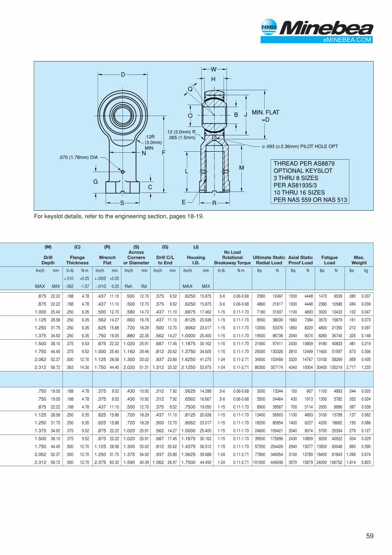
59
DW
H
Q
F
M
N
GC
L
E
O J MIN. FLAT=D
B
S R
.070 (1.78mm) DIA
.12R(3.0mm)MIN
.12 (3.0mm) R.065 (1.5mm)
Ø .093 (Ø 2.36mm) PILOT HOLE OPT
THREAD PER AS8879OPTIONAL KEYSLOT3 THRU 8 SIZESPER AS81935/310 THRU 16 SIZESPER NAS 559 OR NAS 513
For keyslot details, refer to the engineering section, pages 18-19.
(M) (C) (R) (S) (G) (J)Across No Load
Drill Flange Wrench Corners Drill C/L Housing Rotational Ultimate Static Axial Static Fatigue Max.Depth Thickness Flat or Diameter to End I.D. Breakaway Torque Radial Load Proof Load Load Weight
Inch mm In-lb N-m Inch mm Inch mm Inch mm Inch mm In-lb N-m lbs N lbs N lbs N
+.010 +0.25 +.002 +0.05
MAX MAX -.062 -1.57 -.010 -0.25 Ref. Ref. MAX MAX
.875 22.22 .188 4.78 .437 11.10 .500 12.70 .375 9.52 .6250 15.875 .5-6 0.06-0.68 2360 10497 1000 4448 1470 6539
.875 22.22 .188 4.78 .437 11.10 .500 12.70 .375 9.52 .6250 15.875 .5-6 0.06-0.68 4860 21617 1000 4448 2380 10586
1.000 25.40 .250 6.35 .500 12.70 .580 14.73 .437 11.10 .6875 17.462 1-15 0.11-1.70 7180 31937 1100 4893 3020 13433
1.125 28.58 .250 6.35 .562 14.27 .660 16.76 .437 11.10 .8125 20.638 1-15 0.11-1.70 8550 38030 1660 7384 3570 15879
1.250 31.75 .250 6.35 .625 15.88 .720 18.29 .500 12.70 .9062 23.017 1-15 0.11-1.70 12000 53376 1850 8229 4800 21350
1.375 34.92 .250 6.35 .750 19.05 .880 22.35 .562 14.27 1.0000 25.400 1-15 0.11-1.70 19500 86736 2040 9074 8260 36740
1.500 38.10 .375 9.53 .875 22.22 1.020 25.91 .687 17.45 1.1875 30.162 1-15 0.11-1.70 21900 97411 2430 10809 9180 40833
1.750 44.45 .375 9.52 1.000 25.40 1.160 29.46 .812 20.62 1.3750 34.925 1-15 0.11-1.70 29300 130326 2810 12499 11600 51597
2.062 52.37 .500 12.70 1.125 28.58 1.300 33.02 .937 23.80 1.6250 41.275 1-24 0.11-2.71 34500 153456 3320 14767 13100 58269
2.312 58.72 .563 14.30 1.750 44.45 2.020 51.31 1.312 33.32 2.1250 53.975 1-24 0.11-2.71 80300 357174 4340 19304 30400 135219
.750 19.05 .188 4.78 .375 9.52 .430 10.92 .312 7.92 .5625 14.288 .5-6 0.06-0.68 3000 13344 150 667 1100 4893
.750 19.05 .188 4.78 .375 9.52 .430 10.92 .312 7.92 .6562 16.667 .5-6 0.06-0.68 5500 24464 430 1913 1300 5782
.875 22.22 .188 4.78 .437 11.10 .500 12.70 .375 9.52 .7500 19.050 1-15 0.11-1.70 8900 39587 700 3114 2000 8896
1.125 28.58 .250 6.35 .625 15.88 .720 18.29 .437 11.10 .8125 20.638 1-15 0.11-1.70 13400 56903 1100 4893 3100 13789
1.250 31.75 .250 6.35 .625 15.88 .720 18.29 .500 12.70 .9062 23.017 1-15 0.11-1.70 18200 80954 1400 6227 4200 18682
1.375 34.92 .375 9.52 .875 22.22 1.020 25.91 .562 14.27 1.0000 25.400 1-15 0.11-1.70 24600 109421 2040 9074 5700 25354
1.500 38.10 .375 9.52 .875 22.22 1.020 25.91 .687 17.45 1.1875 30.162 1-15 0.11-1.70 39500 175696 2430 10809 9200 40922
1.750 44.45 .500 12.70 1.125 28.58 1.300 33.02 .812 20.62 1.4375 36.512 1-15 0.11-1.70 57200 254426 2940 13077 13500 60048
2.062 52.37 .500 12.70 1.250 31.75 1.375 34.92 .937 23.80 1.5625 39.688 1-24 0.11-2.71 77800 346054 3100 13789 18400 81843
2.312 58.72 .500 12.70 2.375 60.32 1.590 40.39 1.062 26.97 1.7500 44.450 1-24 0.11-2.71 101000 449248 3570 15879 24000 106752
lbs kg
.080 0.037
.084 0.039
.102 0.047
.161 0.073
.212 0.097
.325 0.148
.481 0.219
.673 0.306
.959 0.435
2.717 1.233
.044 0.020
.052 0.024
.087 0.039
.137 0.062
.193 0.088
.279 0.127
.504 0.229
.860 0.390
1.266 0.574
1.814 0.823
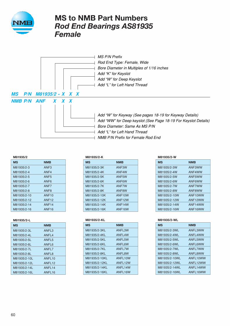
60
MS to NMB Part NumbersRod End Bearings AS81935Female
MS P/N PrefixRod End Type: Female, WideBore Diameter in Multiples of 1/16 inchesAdd “K” for KeyslotAdd “W” for Deep KeyslotAdd “L” for Left Hand Thread
Add “W” for Keyway (See pages 18-19 for Keyway Details)Add “WW” for Deep keyslot (See Page 18-19 For Keyslot Details)Bore Diameter: Same As MS P/NAdd “L” for Left Hand ThreadNMB P/N Prefix for Female Rod End
MS P/N M81935/2 - X X XNMB P/N ANF X X X
M81935/2-WL
MS NMB
M81935/2-3WL ANFL3WW
M81935/2-4WL ANFL4WW
M81935/2-5WL ANFL5WW
M81935/2-6WL ANFL6WW
M81935/2-7WL ANFL7WW
M81935/2-8WL ANFL8WW
M81935/2-10WL ANFL10WW
M81935/2-12WL ANFL12WW
M81935/2-14WL ANFL14WW
M81935/2-16WL ANFL16WW
M81935/2-KL
MS NMB
M81935/2-3KL ANFL3W
M81935/2-4KL ANFL4W
M81935/2-5KL ANFL5W
M81935/2-6KL ANFL6W
M81935/2-7KL ANFL7W
M81935/2-8KL ANFL8W
M81935/2-10KL ANFL10W
M81935/2-12KL ANFL12W
M81935/2-14KL ANFL14W
M81935/2-16KL ANFL16W
M81935/2-L
MS NMB
M81935/2-3L ANFL3
M81935/2-4L ANFL4
M81935/2-5L ANFL5
M81935/2-6L ANFL6
M81935/2-7L ANFL7
M81935/2-8L ANFL8
M81935/2-10L ANFL10
M81935/2-12L ANFL12
M81935/2-14L ANFL14
M81935/2-16L ANFL16
M81935/2
MS NMB
M81935/2-3 ANF3
M81935/2-4 ANF4
M81935/2-5 ANF5
M81935/2-6 ANF6
M81935/2-7 ANF7
M81935/2-8 ANF8
M81935/2-10 ANF10
M81935/2-12 ANF12
M81935/2-14 ANF14
M81935/2-16 ANF16
M81935/2-K
MS NMB
M81935/2-3K ANF3W
M81935/2-4K ANF4W
M81935/2-5K ANF5W
M81935/2-6K ANF6W
M81935/2-7K ANF7W
M81935/2-8K ANF8W
M81935/2-10K ANF10W
M81935/2-12K ANF12W
M81935/2-14K ANF14W
M81935/2-16K ANF16W
M81935/2-W
MS NMB
M81935/2-3W ANF3WW
M81935/2-4W ANF4WW
M81935/2-5W ANF5WW
M81935/2-6W ANF6WW
M81935/2-7W ANF7WW
M81935/2-8W ANF8WW
M81935/2-10W ANF10WW
M81935/2-12W ANF12WW
M81935/2-14W ANF14WW
M81935/2-16W ANF16WW
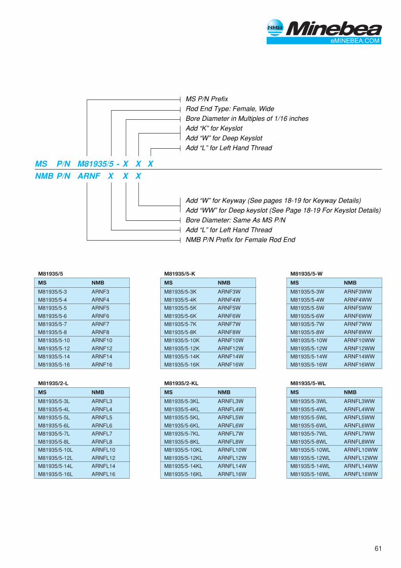
61
MS P/N PrefixRod End Type: Female, WideBore Diameter in Multiples of 1/16 inchesAdd “K” for KeyslotAdd “W” for Deep KeyslotAdd “L” for Left Hand Thread
Add “W” for Keyway (See pages 18-19 for Keyway Details)Add “WW” for Deep keyslot (See Page 18-19 For Keyslot Details)Bore Diameter: Same As MS P/NAdd “L” for Left Hand ThreadNMB P/N Prefix for Female Rod End
MS P/N M81935/5 - X X XNMB P/N ARNF X X X
M81935/5-WL
MS NMB
M81935/5-3WL ARNFL3WW
M81935/5-4WL ARNFL4WW
M81935/5-5WL ARNFL5WW
M81935/5-6WL ARNFL6WW
M81935/5-7WL ARNFL7WW
M81935/5-8WL ARNFL8WW
M81935/5-10WL ARNFL10WW
M81935/5-12WL ARNFL12WW
M81935/5-14WL ARNFL14WW
M81935/5-16WL ARNFL16WW
M81935/2-KL
MS NMB
M81935/5-3KL ARNFL3W
M81935/5-4KL ARNFL4W
M81935/5-5KL ARNFL5W
M81935/5-6KL ARNFL6W
M81935/5-7KL ARNFL7W
M81935/5-8KL ARNFL8W
M81935/5-10KL ARNFL10W
M81935/5-12KL ARNFL12W
M81935/5-14KL ARNFL14W
M81935/5-16KL ARNFL16W
M81935/2-L
MS NMB
M81935/5-3L ARNFL3
M81935/5-4L ARNFL4
M81935/5-5L ARNFL5
M81935/5-6L ARNFL6
M81935/5-7L ARNFL7
M81935/5-8L ARNFL8
M81935/5-10L ARNFL10
M81935/5-12L ARNFL12
M81935/5-14L ARNFL14
M81935/5-16L ARNFL16
M81935/5
MS NMB
M81935/5-3 ARNF3
M81935/5-4 ARNF4
M81935/5-5 ARNF5
M81935/5-6 ARNF6
M81935/5-7 ARNF7
M81935/5-8 ARNF8
M81935/5-10 ARNF10
M81935/5-12 ARNF12
M81935/5-14 ARNF14
M81935/5-16 ARNF16
M81935/5-K
MS NMB
M81935/5-3K ARNF3W
M81935/5-4K ARNF4W
M81935/5-5K ARNF5W
M81935/5-6K ARNF6W
M81935/5-7K ARNF7W
M81935/5-8K ARNF8W
M81935/5-10K ARNF10W
M81935/5-12K ARNF12W
M81935/5-14K ARNF14W
M81935/5-16K ARNF16W
M81935/5-W
MS NMB
M81935/5-3W ARNF3WW
M81935/5-4W ARNF4WW
M81935/5-5W ARNF5WW
M81935/5-6W ARNF6WW
M81935/5-7W ARNF7WW
M81935/5-8W ARNF8WW
M81935/5-10W ARNF10WW
M81935/5-12W ARNF12WW
M81935/5-14W ARNF14WW
M81935/5-16W ARNF16WW
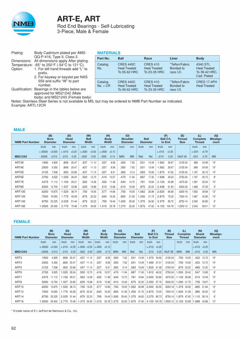
62
Plating: Body Cadmium plated per AMS-QQ-P-416, Type II, Class 2.
Dimensions: All dimensions apply After plating.Temperature: -65° to 250°F (-54°C to 121°C).Option: 1. For left hand threads add “L” to
prefix.2. For keyway or keyslot per NAS
559 and suffix “W” to partnumber.
Qualification: Bearings in the tables below areapproved for MS21242 (Malebody) and MS21243 (Female body)
Notes: Stainless Steel Series is not available to MS, but may be ordered to NMB Part Number as indicated.Example: ARTL12CR
ART-E, ARTRod End Bearings - Self-Lubricating3-Piece, Male & Female
MATERIALSPart No. Ball Race Liner Body
Catalog CRES 440C CRES 410 *Teflon/Fabric 4340 STLNo. Heat Treated Heat Treated Bonded to Heat Treated
To 55-62 HRC To 23-35 HRC race I.D. To 39-42 HRC,Cad. Plated
Catalog CRES 440C CRES 410 *Teflon/Fabric CRES 17-4PHNo. + CR Heat Treated Heat Treated Bonded to Heat Treated
To 55-62 HRC To 23-35 HRC race I.D.
MALE(B) (D) (W) (H) (O) (F) (E) (L) (Q)
Bore Head Ball Body Shoulder Ball Ball C/L Thread Complete Misalign-NMB Part Number Diameter Diameter Width Width Diameter Diameter to End Size Thread ment
Inch mm Inch mm Inch mm Inch mm Inch mm Inch mm Inch mm Inch mm
+.0000 +0.000 +.010 +0.25 +.000 +0.00 +.005 +0.13 +.010 +0.25 +.031 +0.79
MS21242 -.0005 -0.013 -.010 -0.25 -.002 -0.05 -.005 -0.13 MIN MIN Ref. Ref. -.010 -0.25 UNJF-3A -.031 -0.79 MIN
ART3E .1900 4.826 .806 20.47 .437 11.10 .337 8.56 .300 7.62 .531 13.49 1.562 39.67 .3125-24 .968 24.59 15°
ART4E .2500 6.350 .806 20.47 .437 11.10 .337 8.56 .300 7.62 .531 13.49 1.562 39.67 .3125-24 .968 24.59 15°
ART5E .3125 7.938 .900 22.86 .437 11.10 .327 8.31 .360 9.14 .593 15.06 1.875 47.62 .3125-24 1.187 30.15 14°
ART6E .3750 9.525 1.025 26.04 .500 12.70 .416 10.57 .470 11.94 .687 17.45 1.938 49.23 .3750-24 1.187 30.15 8°
ART7E .4375 11.112 1.150 29.21 .562 14.28 .452 11.48 .540 13.72 .781 19.84 2.125 53.98 .4375-20 1.281 32.54 10°
ART8E .5000 12.700 1.337 33.96 .625 15.88 .515 13.08 .610 15.49 .875 22.22 2.438 61.93 .5000-20 1.468 37.29 9°
ART10E .6250 15.875 1.525 38.74 .750 19.05 .577 14.66 .750 19.05 1.062 26.98 2.625 66.68 .6250-18 1.562 39.68 12°
ART12E .7500 19.050 1.775 45.08 .875 22.22 .640 16.26 .850 21.59 1.250 31.75 2.875 73.02 .7500-16 1.687 42.85 13°
ART14E .8750 22.225 2.025 51.44 .875 22.22 .765 19.43 1.000 25.40 1.375 34.92 3.375 85.72 .8750-14 2.000 50.80 6°
ART16E 1.0000 25.400 2.775 70.48 1.375 34.92 1.015 25.78 1.270 32.26 1.875 47.62 4.125 104.78 1.2500-12 2.343 59.51 12°
FEMALE
(B) (D) (W) (H) (O) (F) (E) (L) (N) (Q)Bore Head Ball Body Shoulder Ball Ball C/L Thread Complete Shank Misalign-
NMB Part Number Diameter Diameter Width Width Diameter Diameter to End Size Thread Diameter ment
Inch mm Inch mm Inch mm Inch mm Inch mm Inch mm Inch mm Inch mm Inch mm
+.0000 +0.000 +.010 +0.25 +.000 +0.00 +.005 +0.13 +.010 +0.25 +.010 +0.25
MS21243 -.0005 -0.013 -.010 -0.25 -.002 -0.05 -.005 -0.13 MIN MIN Ref. Ref. -.010 -0.25 UNJF-3B MIN MIN -.010 -0.25 MIN
ART3 .1900 4.826 .806 20.47 .437 11.10 .337 8.56 .300 7.62 .531 13.49 1.375 34.92 .3125-24 .750 19.05 .422 10.72 15°
ART4 .2500 6.350 .806 20.47 .437 11.10 .337 8.56 .300 7.62 .531 13.49 1.469 37.31 .3125-24 .750 19.05 .422 10.72 15°
ART5 .3125 7.938 .900 22.86 .437 11.10 .327 8.31 .360 9.14 .593 15.06 1.625 41.28 .3750-24 .875 22.22 .485 12.32 14°
ART6 .3750 9.525 1.025 26.04 .500 12.70 .416 10.57 .470 11.94 .687 17.45 1.812 46.02 .3750-24 1.000 25.40 .547 13.89 8°
ART7 .4375 11.112 1.150 29.21 .562 14.28 .452 11.48 .540 13.72 .781 19.84 2.000 50.80 .4375-20 1.125 28.58 .610 15.49 10°
ART8 .5000 12.700 1.337 33.96 .625 15.88 .515 13.08 .610 15.49 .875 22.22 2.250 57.15 .5000-20 1.250 31.75 .735 18.67 9°
ART10 .6250 15.875 1.525 38.74 .750 19.05 .577 14.66 .750 19.05 1.062 26.98 2.500 63.50 .6250-18 1.375 34.92 .860 21.84 12°
ART12 .7500 19.050 1.775 45.08 .875 22.22 .640 16.26 .850 21.59 1.250 31.75 2.875 73.02 .7500-16 1.625 41.28 .985 25.02 13°
ART14 .8750 22.225 2.025 51.44 .875 22.22 .765 19.43 1.000 25.40 1.375 34.92 3.375 85.72 .8750-14 1.875 47.62 1.110 28.19 6°
ART16 1.0000 25.400 2.775 70.48 1.375 34.92 1.015 25.78 1.270 32.26 1.875 47.62 4.125 104.78 1.2500-12 2.125 53.98 1.688 42.88 12°
* A trade name of E.I. duPont de Nemours & Co., Inc.

63
D D
F F
L
N
L
W
HQ
O B
E G
S R
ARTART-E
C
OPTIONALKEYWAYWHEN SPECIFIED
W
HQ
O B
R
E
S
LINERLINER INSPECTIONHOLE
OPTIONALKEYSLOTWHEN SPECIFIED
No LoadHousing Keyway Rotational Ultimate Static Axial Static Fatigue Max.
I.D. Flat Breakaway Torque Radial Load Proof Load Load Weight
Inch mm Inch mm In-lb N-m lbs N lbs N lbs N lbs kg
+.000 +0.00
Ref. Ref. -.020 -0.51
.6250 15.875 .980 24.89 .5-6 0.06-0.68 2360 10497 1000 4448 1470 6539 0.072 0.033
.6250 15.875 .980 24.89 .5-6 0.06-0.68 4860 21617 1000 4448 2380 10586 0.072 0.033
.6875 17.462 1.270 32.26 1-10 0.11-1.13 7180 31937 1100 4893 2770 12321 0.087 0.040
.8125 20.638 1.235 31.37 1-10 0.11-1.13 8550 38030 1660 7384 3570 15879 0.136 0.062
.9062 23.017 1.402 35.61 1-10 0.11-1.13 12000 53376 1850 8229 4800 21350 0.183 0.083
1.0000 25.400 1.589 40.36 1-10 0.11-1.13 19500 86736 2040 9074 7680 34161 0.278 0.127
1.1875 30.162 1.683 42.75 1-10 0.11-1.13 21900 97411 2430 10809 9180 40833 0.424 0.193
1.3750 34.925 1.808 45.92 1-10 0.11-1.13 29300 130326 2810 12499 11600 51597 0.639 0.290
1.6250 41.275 2.121 53.87 2-16 0.23-1.81 34500 153456 3320 14767 13100 58269 0.963 0.437
2.1250 53.975 2.464 62.59 2-16 0.23-1.81 80300 357174 4340 19304 30400 135219 2.546 1.155
(C) (R) (S) (G) No LoadAcross Rotational
Flange Wrench Corners Drill C/L Housing Breakaway Ultimate Static Axial Static Fatigue MAXThickness Flat or Diameter to End I.D. Torque Radial Load Proof Load Load Weight
Inch mm Inch mm Inch mm Inch mm Inch mm In-lb N-m lbs N lbs N lbs N lbs kg
+.010 +0.25 +.002 +0.05 +.020 +0.51
-.062 -1.57 -.010 -0.25 Ref. Ref. -.020 -0.51 Ref. Ref.
.188 4.78 .437 11.10 .500 12.70 .375 9.52 .6250 15.875 .5-6 0.06-0.68 2360 10487 1000 4448 1470 6539 .080 0.037
.188 4.78 .437 11.10 .500 12.70 .375 9.52 .6250 15.875 .5-6 0.06-0.68 4860 21617 1000 4448 2380 10586 .084 0.039
.250 6.35 .500 12.70 .580 14.73 .437 11.10 .6875 17.462 1-10 0.11-1.13 7180 31937 1100 4893 3020 13433 .102 0.047
.250 6.35 .562 14.27 .660 16.76 .437 11.10 .8125 20.638 1-10 0.11-1.13 8550 38030 1660 7384 3570 15879 .161 0.073
.250 6.35 .625 15.88 .720 18.29 .500 12.70 .9062 23.017 1-10 0.11-1.13 12000 53376 1850 8229 4800 21350 .212 0.097
.250 6.35 .750 19.05 .880 22.35 .562 14.28 1.0000 25.400 1-10 0.11-1.13 19500 86736 2040 9074 8260 36740 .325 0.148
.375 9.52 .875 22.22 1.020 25.91 .687 17.45 1.1875 30.162 1-10 0.11-1.13 21900 97411 2430 10809 9180 40833 .481 0.219
.375 9.52 1.000 25.40 1.160 29.46 .812 20.62 1.3750 34.925 1-10 0.11-1.13 29300 130326 2810 12499 11600 51597 .673 0.306
.500 12.70 1.125 28.38 1.300 33.02 .937 23.80 1.6250 41.275 2-16 0.23-1.81 34500 153456 3320 14767 13100 58269 .959 0.435
.563 14.30 1.750 44.45 2.020 51.31 1.312 33.32 2.1250 53.975 2-16 0.23-1.81 80300 357174 4340 19304 30400 135219 2.717 1.233
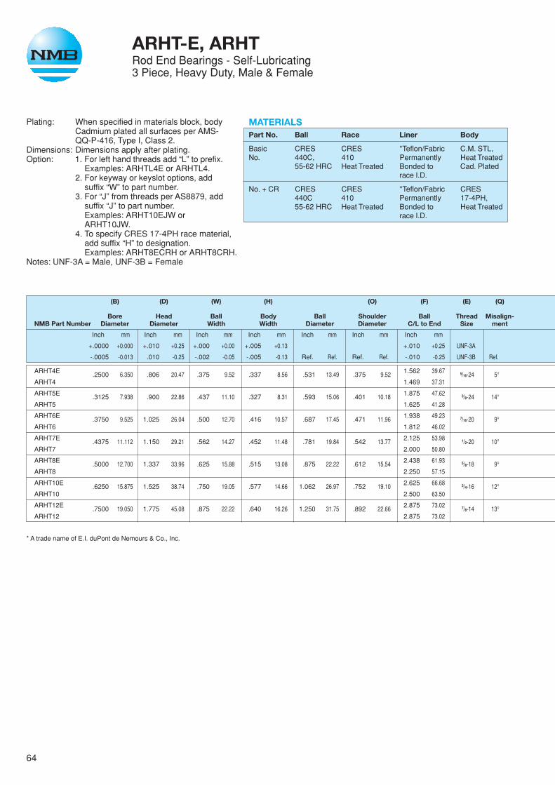
64
(B) (D) (W) (H) (O) (F) (E) (Q)
Bore Head Ball Body Ball Shoulder Ball Thread Misalign-NMB Part Number Diameter Diameter Width Width Diameter Diameter C/L to End Size ment
Inch mm Inch mm Inch mm Inch mm Inch mm Inch mm Inch mm
+.0000 +0.000 +.010 +0.25 +.000 +0.00 +.005 +0.13 +.010 +0.25 UNF-3A
-.0005 -0.013 .010 -0.25 -.002 -0.05 -.005 -0.13 Ref. Ref. Ref. Ref. -.010 -0.25 UNF-3B Ref.
ARHT4E .2500 6.350 .806 20.47 .375 9.52 .337 8.56 .531 13.49 .375 9.52 1.562 39.67 5/16-24 5°ARHT4 1.469 37.31
ARHT5E .3125 7.938 .900 22.86 .437 11.10 .327 8.31 .593 15.06 .401 10.18 1.875 47.62 3/8-24 14°ARHT5 1.625 41.28
ARHT6E .3750 9.525 1.025 26.04 .500 12.70 .416 10.57 .687 17.45 .471 11.96 1.938 49.23 7/16-20 9°ARHT6 1.812 46.02
ARHT7E .4375 11.112 1.150 29.21 .562 14.27 .452 11.48 .781 19.84 .542 13.77 2.125 53.98 1/2-20 10°ARHT7 2.000 50.80
ARHT8E .5000 12.700 1.337 33.96 .625 15.88 .515 13.08 .875 22.22 .612 15.54 2.438 61.93 5/8-18 9°ARHT8 2.250 57.15
ARHT10E .6250 15.875 1.525 38.74 .750 19.05 .577 14.66 1.062 26.97 .752 19.10 2.625 66.68 3/4-16 12°ARHT10 2.500 63.50
ARHT12E .7500 19.050 1.775 45.08 .875 22.22 .640 16.26 1.250 31.75 .892 22.66 2.875 73.02 7/8-14 13°ARHT12 2.875 73.02
* A trade name of E.I. duPont de Nemours & Co., Inc.
Plating: When specified in materials block, bodyCadmium plated all surfaces per AMS-QQ-P-416, Type I, Class 2.
Dimensions: Dimensions apply after plating.Option: 1. For left hand threads add “L” to prefix.
Examples: ARHTL4E or ARHTL4.2. For keyway or keyslot options, add
suffix “W” to part number.3. For “J” from threads per AS8879, add
suffix “J” to part number.Examples: ARHT10EJW orARHT10JW.
4. To specify CRES 17-4PH race material,add suffix “H” to designation.Examples: ARHT8ECRH or ARHT8CRH.
Notes: UNF-3A = Male, UNF-3B = Female
ARHT-E, ARHTRod End Bearings - Self-Lubricating3 Piece, Heavy Duty, Male & Female
MATERIALSPart No. Ball Race Liner Body
Basic CRES CRES *Teflon/Fabric C.M. STL,No. 440C, 410 Permanently Heat Treated
55-62 HRC Heat Treated Bonded to Cad. Platedrace I.D.
No. + CR CRES CRES *Teflon/Fabric CRES440C 410 Permanently 17-4PH,55-62 HRC Heat Treated Bonded to Heat Treated
race I.D.
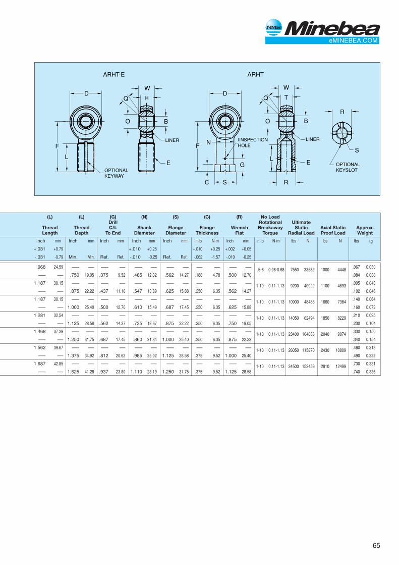
65
(L) (L) (G) (N) (S) (C) (R) No LoadDrill Rotational Ultimate
Thread Thread C/L Shank Flange Flange Wrench Breakaway Static Axial Static Approx.Length Depth To End Diameter Diameter Thickness Flat Torque Radial Load Proof Load Weight
Inch mm Inch mm Inch mm Inch mm Inch mm In-lb N-m Inch mm In-lb N-m lbs N lbs N lbs kg
+.031 +0.79 +.010 +0.25 +.010 +0.25 +.002 +0.05
-.031 -0.79 Min. Min. Ref. Ref. -.010 -0.25 Ref. Ref. -.062 -1.57 -.010 -0.25
.968 24.59 –— –— –— –— –— –— –— –— –— –— –— –— .5-6 0.06-0.68 7550 33582 1000 4448 .067 0.030
–— –— .750 19.05 .375 9.52 .485 12.32 .562 14.27 .188 4.78 .500 12.70 .084 0.038
1.187 30.15 –— –— –— –— –— –— –— –— –— –— –— –— 1-10 0.11-1.13 9200 40922 1100 4893 .095 0.043
–— –— .875 22.22 .437 11.10 .547 13.89 .625 15.88 .250 6.35 .562 14.27 .102 0.046
1.187 30.15 –— –— –— –— –— –— –— –— –— –— –— –— 1-10 0.11-1.13 10900 48483 1660 7384 .140 0.064
–— –— 1.000 25.40 .500 12.70 .610 15.49 .687 17.45 .250 6.35 .625 15.88 .160 0.073
1.281 32.54 –— –— –— –— –— –— –— –— –— –— –— –— 1-10 0.11-1.13 14050 62494 1850 8229 .210 0.095
–— –— 1.125 28.58 .562 14.27 .735 18.67 .875 22.22 .250 6.35 .750 19.05 .230 0.104
1.468 37.29 –— ––— –— –— –— –— –— –— –— –— –— –— 1-10 0.11-1.13 23400 104083 2040 9074 .330 0.150
–— –— 1.250 31.75 .687 17.45 .860 21.84 1.000 25.40 .250 6.35 .875 22.22 .340 0.154
1.562 39.67 –— –— –— –— –— –— –— –— –— –— –— –— 1-10 0.11-1.13 26050 115870 2430 10809 .480 0.218
–— –— 1.375 34.92 .812 20.62 .985 25.02 1.125 28.58 .375 9.52 1.000 25.40 .490 0.222
1.687 42.85 –— –— –— –— –— –— –— –— –— –— –— –— 1-10 0.11-1.13 34500 153456 2810 12499 .730 0.331
–— –— 1.625 41.28 .937 23.80 1.110 28.19 1.250 31.75 .375 9.52 1.125 28.58 .740 0.336
D D
F F
L
N
L
W
HQ
O B
E G
S R
ARHTARHT-E
C
OPTIONALKEYWAY
W
TQ
O B
R
E
S
LINERLINER IINSPECTIONHOLE
OPTIONALKEYSLOT

66
Plating: When specified in materials block, bodyCadmium plated all surfaces per AMS-QQ-P-416, Type I, Class 2.
Dimensions: Dimensions apply after plating.Option: 1. For left hand threads add “L” to prefix.
Examples: ARYTL4E or ARYTL4.2. For keyway or keyslot options, add
suffix “W” to part number.3. For “J” from threads per MIL-S-8879,
add suffix “J” to part number.Examples: ARYT12JW or ARYT12J.
4. To specify CRES 17-4PH race mate-rial, add suffix “H” to designation.Examples: ARYT8ECRH or ARYT8CRH.
Notes: UNF-3A = Male Thread, UNF-3B = Female Thread
ARYT-E, ARYTRod End Bearings - Self -Lubricating3 Piece, High Misalignment, Male & Female
MATERIALSPart No. Ball Race Liner Body
Basic CRES CRES *Teflon/Fabric C.M. STL,No. 440C, 410 Permanently Heat Treated
55-62 HRC Heat Treated Bonded to Cad. Platedrace I.D.
No. + CR CRES CRES *Teflon/Fabric CRES440C 410 Permanently 17-4PH,55-62 HRC Heat Treated Bonded to Heat Treated
race I.D.
(B) (D) (W) (H) (O) (F) (E) (Q)
Bore Head Ball Body Shoulder Ball Ball C/L Thread Misalign-NMB Part Number Diameter Diameter Width Width Diameter Diameter to End Size ment
Inch mm Inch mm Inch mm Inch mm Inch mm Inch mm Inch mm
+.0000 +0.000 +.010 +0.25 +.000 +0.00 +.005 +0.13 +.031 +0.79 UNF-3A
-.0005 -0.013 -.010 -0.25 -.005 -0.13 -.005 -0.13 Ref. Ref. Ref. Ref. -.031 -0.79 UNF-3B Ref.
ARYT3E.1900 4.826 .750 19.05 .500 12.70 .220 5.59 .319 8.10 .437 11.10
1.500 38.105/16-24 13°
ARYT3 1.375 34.92
ARYT4E.2500 6.350 1.000 25.40 .593 15.06 .265 6.73 .390 9.91 .593 15.06
1.938 49.223/8-24 23°
ARYT4 1.625 41.28
ARYT5E.3125 7.938 1.125 28.58 .813 20.65 .355 9.02 .512 13.00 .781 19.84
2.125 53.987/16-20 22°
ARYT5 1.812 46.02
ARYT6E.3750 9.525 1.125 28.58 .813 20.65 .355 9.02 .512 13.00 .781 19.84
2.125 53.987/16-20 22°
ARYT6 1.812 46.02
ARYT7E.4375 11.112 1.312 33.32 .875 22.22 .355 9.02 .618 15.70 .875 22.22
2.438 61.931/2-20 21°
ARYT7 2.125 52.98
ARYT8E.5000 12.700 1.500 38.10 .937 23.80 .411 10.44 .730 18.54 1.000 25.40
2.625 66.685/8-18 19°
ARYT8 2.625 66.68
ARYT10E.6250 15.875 1.7500 44.45 1.200 30.48 .577 14.66 .856 21.74 1.250 31.75
2.875 73.023/4-16 19°
ARYT10 2.875 73.02
ARYT12E.7500 19.050 2.000 50.80 1.280 32.51 .630 16.00 .970 24.64 1.375 34.92
3.375 85.727/8-14 18°
ARYT12 3.375 86.72
ARYT14E.8750 22.225 2.200 55.88 1.400 35.56 .635 16.13 1.140 28.96 1.531 38.89
3.750 95.257/8-14 17°
ARYT14 3.750 95.25
ARYT16E1.000 25.400 2.750 69.85 1.875 47.62 .845 21.46 1.278 32.46 1.875 47.62
4.125 104.7811/4-12 20°
ARYT16 4.125 104.78
ARYT20E1.2500 31.750 3.125 79.38 1.875 47.62 1.015 25.78 1.523 38.68 2.250 57.15
5.000 127.0011/4-12 20°
ARYT20 5.000 127.00
* A trade name of E.I. duPont de Nemours & Co., Inc.
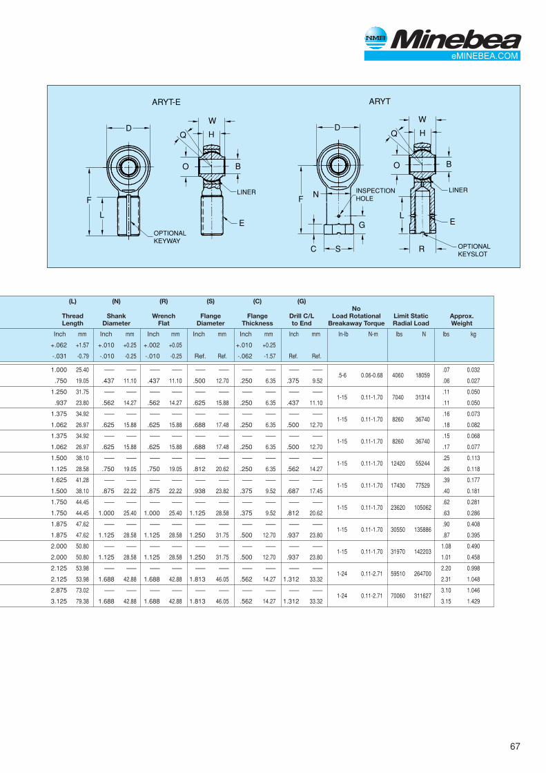
67
D D
F F
L
N
L
W
HQ
O B
E G
S R
ARYTARYT-E
C
OPTIONALKEYWAY
W
HQ
O B
E
LINERLINER INSPECTIONHOLE
OPTIONALKEYSLOT
(L) (N) (R) (S) (C) (G)No
Thread Shank Wrench Flange Flange Drill C/L Load Rotational Limit Static Approx.Length Diameter Flat Diameter Thickness to End Breakaway Torque Radial Load Weight
Inch mm Inch mm Inch mm Inch mm Inch mm Inch mm In-lb N-m lbs N lbs kg
+.062 +1.57 +.010 +0.25 +.002 +0.05 +.010 +0.25
-.031 -0.79 -.010 -0.25 -.010 -0.25 Ref. Ref. -.062 -1.57 Ref. Ref.
1.000 25.40 –— –— –— –— –— –— –— –— –— –—.5-6 0.06-0.68 4060 18059
.07 0.032
.750 19.05 .437 11.10 .437 11.10 .500 12.70 .250 6.35 .375 9.52 .06 0.027
1.250 31.75 –— –— –— –— –— –— –— –— –— –—1-15 0.11-1.70 7040 31314
.11 0.050
.937 23.80 .562 14.27 .562 14.27 .625 15.88 .250 6.35 .437 11.10 .11 0.050
1.375 34.92 –— –— –— –— –— –— –— –— –— –—1-15 0.11-1.70 8260 36740
.16 0.073
1.062 26.97 .625 15.88 .625 15.88 .688 17.48 .250 6.35 .500 12.70 .18 0.082
1.375 34.92 –— –— –— –— –— –— –— –— –— –—1-15 0.11-1.70 8260 36740
.15 0.068
1.062 26.97 .625 15.88 .625 15.88 .688 17.48 .250 6.35 .500 12.70 .17 0.077
1.500 38.10 –— –— –— –— –— –— –— –— –— –—1-15 0.11-1.70 12420 55244
.25 0.113
1.125 28.58 .750 19.05 .750 19.05 .812 20.62 .250 6.35 .562 14.27 .26 0.118
1.625 41.28 –— –— –— –— –— –— –— –— –— –—1-15 0.11-1.70 17430 77529
.39 0.177
1.500 38.10 .875 22.22 .875 22.22 .938 23.82 .375 9.52 .687 17.45 .40 0.181
1.750 44.45 –— –— –— –— –— –— –— –— –— –—1-15 0.11-1.70 23620 105062
.62 0.281
1.750 44.45 1.000 25.40 1.000 25.40 1.125 28.58 .375 9.52 .812 20.62 .63 0.286
1.875 47.62 –— –— –— –— –— –— –— –— –— –—1-15 0.11-1.70 30550 135886
.90 0.408
1.875 47.62 1.125 28.58 1.125 28.58 1.250 31.75 .500 12.70 .937 23.80 .87 0.395
2.000 50.80 –— –— –— –— –— –— –— –— –— –—1-15 0.11-1.70 31970 142203
1.08 0.490
2.000 50.80 1.125 28.58 1.125 28.58 1.250 31.75 .500 12.70 .937 23.80 1.01 0.458
2.125 53.98 –— –— –— –— –— –— –— –— –— –—1-24 0.11-2.71 59510 264700
2.20 0.998
2.125 53.98 1.688 42.88 1.688 42.88 1.813 46.05 .562 14.27 1.312 33.32 2.31 1.048
2.875 73.02 –— –— –— –— –— –— –— –— –— –—1-24 0.11-2.71 70060 311627
3.10 1.046
3.125 79.38 1.688 42.88 1.688 42.88 1.813 46.05 .562 14.27 1.312 33.32 3.15 1.429
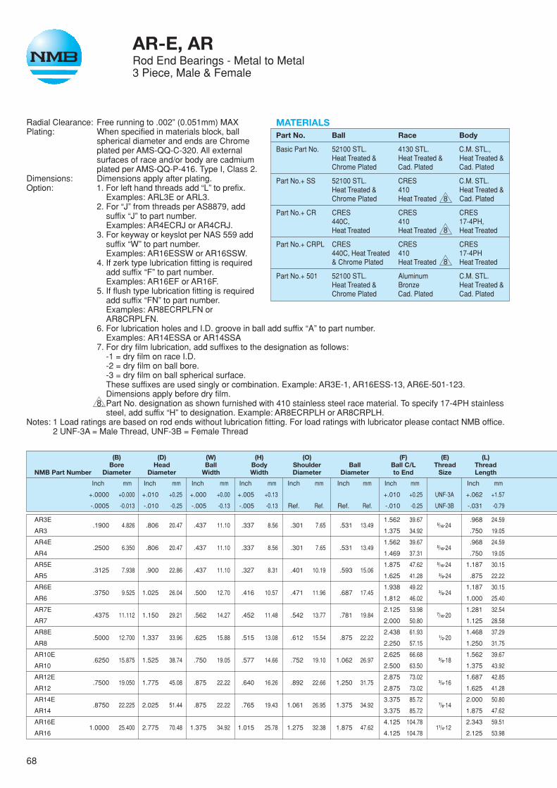
68
AR-E, ARRod End Bearings - Metal to Metal3 Piece, Male & Female
Radial Clearance: Free running to .002” (0.051mm) MAXPlating: When specified in materials block, ball
spherical diameter and ends are Chromeplated per AMS-QQ-C-320. All externalsurfaces of race and/or body are cadmiumplated per AMS-QQ-P-416. Type I, Class 2.
Dimensions: Dimensions apply after plating.Option: 1. For left hand threads add “L” to prefix.
Examples: ARL3E or ARL3.2. For “J” from threads per AS8879, add
suffix “J” to part number.Examples: AR4ECRJ or AR4CRJ.
3. For keyway or keyslot per NAS 559 addsuffix “W” to part number.Examples: AR16ESSW or AR16SSW.
4. If zerk type lubrication fitting is requiredadd suffix “F” to part number.Examples: AR16EF or AR16F.
5. If flush type lubrication fitting is requiredadd suffix “FN” to part number.Examples: AR8ECRPLFN orAR8CRPLFN.
6. For lubrication holes and I.D. groove in ball add suffix “A” to part number.Examples: AR14ESSA or AR14SSA
7. For dry film lubrication, add suffixes to the designation as follows:-1 = dry film on race I.D.-2 = dry film on ball bore.-3 = dry film on ball spherical surface.These suffixes are used singly or combination. Example: AR3E-1, AR16ESS-13, AR6E-501-123.Dimensions apply before dry film.
8. Part No. designation as shown furnished with 410 stainless steel race material. To specify 17-4PH stainlesssteel, add suffix “H” to designation. Example: AR8ECRPLH or AR8CRPLH.
Notes: 1 Load ratings are based on rod ends without lubrication fitting. For load ratings with lubricator please contact NMB office.2 UNF-3A = Male Thread, UNF-3B = Female Thread
(B) (D) (W) (H) (O) (F) (E) (L)Bore Head Ball Body Shoulder Ball Ball C/L Thread Thread
NMB Part Number Diameter Diameter Width Width Diameter Diameter to End Size Length
Inch mm Inch mm Inch mm Inch mm Inch mm Inch mm Inch mm Inch mm
+.0000 +0.000 +.010 +0.25 +.000 +0.00 +.005 +0.13 +.010 +0.25 UNF-3A +.062 +1.57
-.0005 -0.013 -.010 -0.25 -.005 -0.13 -.005 -0.13 Ref. Ref. Ref. Ref. -.010 -0.25 UNF-3B -.031 -0.79
AR3E.1900 4.826 .806 20.47 .437 11.10 .337 8.56 .301 7.65 .531 13.49
1.562 39.675/16-24
.968 24.59
AR3 1.375 34.92 .750 19.05
AR4E.2500 6.350 .806 20.47 .437 11.10 .337 8.56 .301 7.65 .531 13.49
1.562 39.675/16-24
.968 24.59
AR4 1.469 37.31 .750 19.05
AR5E.3125 7.938 .900 22.86 .437 11.10 .327 8.31 .401 10.19 .593 15.06
1.875 47.62 5/16-24 1.187 30.15
AR5 1.625 41.28 3/8-24 .875 22.22
AR6E.3750 9.525 1.025 26.04 .500 12.70 .416 10.57 .471 11.96 .687 17.45
1.938 49.223/8-24
1.187 30.15
AR6 1.812 46.02 1.000 25.40
AR7E.4375 11.112 1.150 29.21 .562 14.27 .452 11.48 .542 13.77 .781 19.84
2.125 53.987/16-20
1.281 32.54
AR7 2.000 50.80 1.125 28.58
AR8E.5000 12.700 1.337 33.96 .625 15.88 .515 13.08 .612 15.54 .875 22.22
2.438 61.931/2-20
1.468 37.29
AR8 2.250 57.15 1.250 31.75
AR10E.6250 15.875 1.525 38.74 .750 19.05 .577 14.66 .752 19.10 1.062 26.97
2.625 66.685/8-18
1.562 39.67
AR10 2.500 63.50 1.375 43.92
AR12E.7500 19.050 1.775 45.08 .875 22.22 .640 16.26 .892 22.66 1.250 31.75
2.875 73.023/4-16
1.687 42.85
AR12 2.875 73.02 1.625 41.28
AR14E.8750 22.225 2.025 51.44 .875 22.22 .765 19.43 1.061 26.95 1.375 34.92
3.375 85.727/8-14
2.000 50.80
AR14 3.375 85.72 1.875 47.62
AR16E1.0000 25.400 2.775 70.48 1.375 34.92 1.015 25.78 1.275 32.38 1.875 47.62
4.125 104.7811/4-12
2.343 59.51
AR16 4.125 104.78 2.125 53.98
MATERIALSPart No. Ball Race Body
Basic Part No. 52100 STL. 4130 STL. C.M. STL.,Heat Treated & Heat Treated & Heat Treated &Chrome Plated Cad. Plated Cad. Plated
Part No.+ SS 52100 STL. CRES C.M. STL.Heat Treated & 410 Heat Treated &Chrome Plated Heat Treated Cad. Plated
Part No.+ CR CRES CRES CRES440C, 410 17-4PH,Heat Treated Heat Treated Heat Treated
Part No.+ CRPL CRES CRES CRES440C, Heat Treated 410 17-4PH& Chrome Plated Heat Treated Heat Treated
Part No.+ 501 52100 STL. Aluminum C.M. STL.Heat Treated & Bronze Heat Treated &Chrome Plated Cad. Plated Cad. Plated
8
8
8
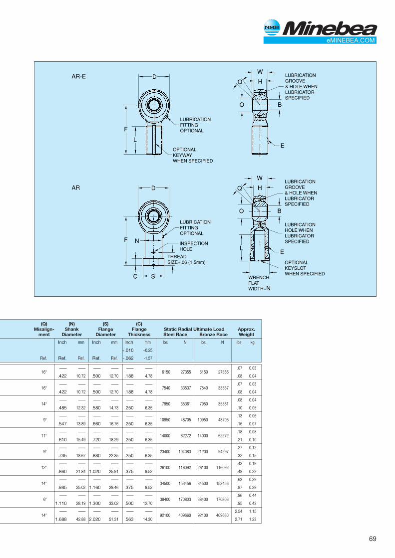
69
D
F
L
W
HQ
O B
E
AR-E
OPTIONALKEYWAYWHEN SPECIFIED
LUBRICATIONFITTINGOPTIONAL
LUBRICATIONGROOVE& HOLE WHENLUBRICATORSPECIFIED
D
FL
N
SC
W
HQ
O B
E
AR
INSPECTIONHOLE
THREADSIZE+.06 (1.5mm)
LUBRICATIONFITTINGOPTIONAL
LUBRICATIONGROOVE& HOLE WHENLUBRICATORSPECIFIED
OPTIONALKEYSLOTWHEN SPECIFIED
LUBRICATIONHOLE WHENLUBRICATORSPECIFIED
WRENCHFLATWIDTH=N
(Q) (N) (S) (C)Misalign- Shank Flange Flange Static Radial Ultimate Load Approx.
ment Diameter Diameter Thickness Steel Race Bronze Race Weight
Inch mm Inch mm Inch mm lbs N lbs N lbs kg
+.010 +0.25
Ref. Ref. Ref. Ref. Ref. -.062 -1.57
16°–— –— –— –— –— –—
6150 27355 6150 27355.07 0.03
.422 10.72 .500 12.70 .188 4.78 .08 0.04
16°–— –— –— –— –— –—
7540 33537 7540 33537.07 0.03
.422 10.72 .500 12.70 .188 4.78 .08 0.04
14°–— –— –— –— –— –—
7950 35361 7950 35361.08 0.04
.485 12.32 .580 14.73 .250 6.35 .10 0.05
9°–— –— –— –— –— –—
10950 48705 10950 48705.13 0.06
.547 13.89 .660 16.76 .250 6.35 .16 0.07
11°–— –— –— –— –— –—
14000 62272 14000 62272.18 0.08
.610 15.49 .720 18.29 .250 6.35 .21 0.10
9°–— –— –— –— –— –—
23400 104083 21200 94297.27 0.12
.735 18.67 .880 22.35 .250 6.35 .32 0.15
12°–— –— –— –— –— –—
26100 116092 26100 116092.42 0.19
.860 21.84 1.020 25.91 .375 9.52 .48 0.22
14°–— –— –— –— –— –—
34500 153456 34500 153456.63 0.29
.985 25.02 1.160 29.46 .375 9.52 .87 0.39
6°–— –— –— –— –— –—
38400 170803 38400 170803.96 0.44
1.110 28.19 1.300 33.02 .500 12.70 .95 0.43
14°–— –— –— –— –— –—
92100 409660 92100 4096602.54 1.15
1.688 42.88 2.020 51.31 .563 14.30 2.71 1.23
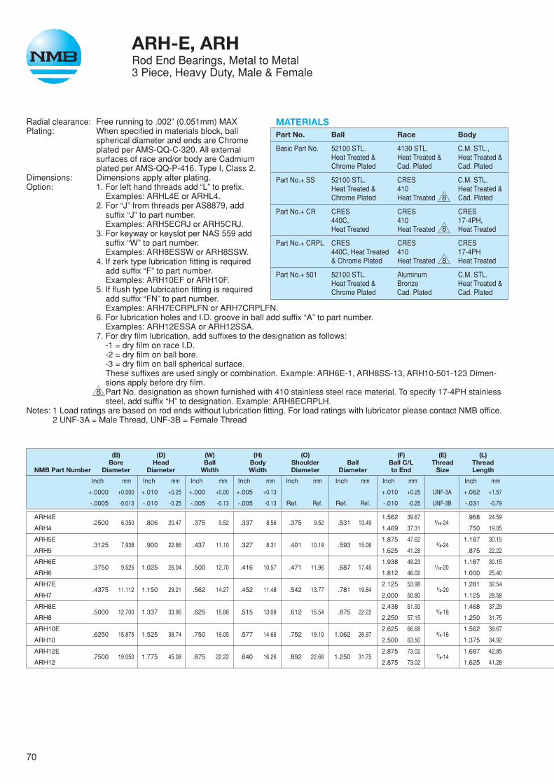
70
ARH-E, ARHRod End Bearings, Metal to Metal3 Piece, Heavy Duty, Male & Female
Radial clearance: Free running to .002” (0.051mm) MAXPlating: When specified in materials block, ball
spherical diameter and ends are Chromeplated per AMS-QQ-C-320. All externalsurfaces of race and/or body are Cadmiumplated per AMS-QQ-P-416. Type I, Class 2.
Dimensions: Dimensions apply after plating.Option: 1. For left hand threads add “L” to prefix.
Examples: ARHL4E or ARHL4.2. For “J” from threads per AS8879, add
suffix “J” to part number.Examples: ARH5ECRJ or ARH5CRJ.
3. For keyway or keyslot per NAS 559 addsuffix “W” to part number.Examples: ARH8ESSW or ARH8SSW.
4. If zerk type lubrication fitting is requiredadd suffix “F” to part number.Examples: ARH10EF or ARH10F.
5. If flush type lubrication fitting is requiredadd suffix “FN” to part number.Examples: ARH7ECRPLFN or ARH7CRPLFN.
6. For lubrication holes and I.D. groove in ball add suffix “A” to part number.Examples: ARH12ESSA or ARH12SSA.
7. For dry film lubrication, add suffixes to the designation as follows:-1 = dry film on race I.D.-2 = dry film on ball bore.-3 = dry film on ball spherical surface.These suffixes are used singly or combination. Example: ARH6E-1, ARH8SS-13, ARH10-501-123 Dimen-sions apply before dry film.
8. Part No. designation as shown furnished with 410 stainless steel race material. To specify 17-4PH stainlesssteel, add suffix “H” to designation. Example: ARH8ECRPLH.
Notes: 1 Load ratings are based on rod ends without lubrication fitting. For load ratings with lubricator please contact NMB office.2 UNF-3A = Male Thread, UNF-3B = Female Thread
(B) (D) (W) (H) (O) (F) (E) (L)Bore Head Ball Body Shoulder Ball Ball C/L Thread Thread
NMB Part Number Diameter Diameter Width Width Diameter Diameter to End Size Length
Inch mm Inch mm Inch mm Inch mm Inch mm Inch mm Inch mm Inch mm
+.0000 +0.000 +.010 +0.25 +.000 +0.00 +.005 +0.13 +.010 +0.25 UNF-3A +.062 +1.57
-.0005 -0.013 -.010 -0.25 -.005 -0.13 -.005 -0.13 Ref. Ref. Ref. Ref. -.010 -0.25 UNF-3B -.031 -0.79
ARH4E.2500 6.350 .806 20.47 .375 9.52 .337 8.56 .375 9.52 .531 13.49
1.562 39.675/16-24
.968 24.59
ARH4 1.469 37.31 .750 19.05
ARH5E.3125 7.938 .900 22.86 .437 11.10 .327 8.31 .401 10.19 .593 15.06
1.875 47.623/8-24
1.187 30.15
ARH5 1.625 41.28 .875 22.22
ARH6E.3750 9.525 1.025 26.04 .500 12.70 .416 10.57 .471 11.96 .687 17.45
1.938 49.237/16-20
1.187 30.15
ARH6 1.812 46.02 1.000 25.40
ARH7E.4375 11.112 1.150 29.21 .562 14.27 .452 11.48 .542 13.77 .781 19.84
2.125 53.981/2-20
1.281 32.54
ARH7 2.000 50.80 1.125 28.58
ARH8E.5000 12.700 1.337 33.96 .625 15.88 .515 13.08 .612 15.54 .875 22.22
2.438 61.935/8-18
1.468 37.29
ARH8 2.250 57.15 1.250 31.75
ARH10E.6250 15.875 1.525 38.74 .750 19.05 .577 14.66 .752 19.10 1.062 26.97
2.625 66.683/4-16
1.562 39.67
ARH10 2.500 63.50 1.375 34.92
ARH12E.7500 19.050 1.775 45.08 .875 22.22 .640 16.26 .892 22.66 1.250 31.75
2.875 73.027/8-14
1.687 42.85
ARH12 2.875 73.02 1.625 41.28
MATERIALSPart No. Ball Race Body
Basic Part No. 52100 STL. 4130 STL. C.M. STL.,Heat Treated & Heat Treated & Heat Treated &Chrome Plated Cad. Plated Cad. Plated
Part No.+ SS 52100 STL. CRES C.M. STL.Heat Treated & 410 Heat Treated &Chrome Plated Heat Treated Cad. Plated
Part No.+ CR CRES CRES CRES440C, 410 17-4PH,Heat Treated Heat Treated Heat Treated
Part No.+ CRPL CRES CRES CRES440C, Heat Treated 410 17-4PH& Chrome Plated Heat Treated Heat Treated
Part No.+ 501 52100 STL. Aluminum C.M. STL.Heat Treated & Bronze Heat Treated &Chrome Plated Cad. Plated Cad. Plated
8
8
8
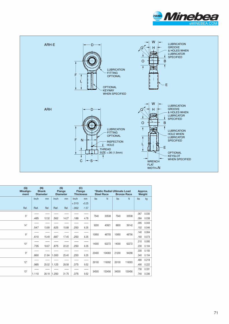
71
D
F
L
W
HQ
O B
E
ARH-E
OPTIONALKEYWAYWHEN SPECIFIED
LUBRICATIONFITTINGOPTIONAL
LUBRICATIONGROOVE& HOLES WHENLUBRICATORSPECIFIED
D
FL
N
SC
W
HQ
O B
E
ARH
INSPECTIONHOLE
THREADSIZE +.06 (1.5mm)
LUBRICATIONFITTINGOPTIONAL
LUBRICATIONGROOVE& HOLES WHENLUBRICATORSPECIFIED
OPTIONALKEYSLOTWHEN SPECIFIED
LUBRICATIONHOLE WHENLUBRICATORSPECIFIED
WRENCHFLATWIDTH=N
(Q) (N) (S) (C)Misalign- Shank Flange Flange *Static Radial Ultimate Load Approx.
ment Diameter Diameter Thickness Steel Race Bronze Race Weight
Inch mm Inch mm Inch mm lbs N lbs N lbs kg
+.010 +0.25
Ref. Ref. Ref. Ref. Ref. -.062 -1.57
5°–— –— –— –— –— –—
7540 33538 7540 33538.067 0.030
.485 12.32 .562 14.27 .188 4.78 .084 0.038
14°–— –— –— –— –— –—
9200 40921 8800 39142.095 0.043
.547 13.89 .625 15.88 .250 6.35 .102 0.046
9°–— –— –— –— –— –—
10950 48705 10950 48706.140 0.064
.610 15.49 .687 17.45 .250 6.35 .160 0.073
10°–— –— –— –— –— –—
14000 62272 14000 62272.210 0.095
.735 18.67 .875 22.22 .250 6.35 .230 0.104
9°–— –— –— –— –— –—
23400 104083 21200 94298.330 0.150
.860 21.84 1.000 25.40 .250 6.35 .340 0.154
12°–— –— –— –— –— –—
26100 116092 26100 116093.480 0.218
.985 25.02 1.125 28.58 .375 9.52 .490 0.222
13°–— –— –— –— –— –—
34500 153456 34500 153456.730 0.331
1.110 28.19 1.250 31.75 .375 9.52 .740 0.336

72
ARYM, ARYFRod End Bearings - Metal to Metal3 Piece, High Misalignment, Male & Female
Radial clearance: Free running to .002” (0.051mm) MAXPlating: When specified in materials block, ball
spherical diameter and ends are Chromeplated per AMS-QQ-C-320. All externalsurfaces of race and/or body are Cadmiumplated per AMS-QQ-P-416. Type I, Class 2.
Dimensions: Dimensions apply after plating.Option: 1. For left hand threads add “L” to prefix.
Examples: ARYML3 or ARYFL3.2. For “J” from threads per AS8879, add
suffix “J” to part number.Examples: ARYM4CRJ or ARYF4CRJ.
3. For keyway or keyslot per NAS 559 addsuffix “W” to part number.Examples: ARYM16SSW or ARYF-16SSW.
4. If zerk type lubrication fitting is requiredadd suffix “F” to part number.Example: ARYM20F or ARYF20F.
5. If flush type lubrication fitting is requiredadd suffix “FN” to part number.Example: ARYM8CRPLFN or ARYF8CRPLFN.
6. For lubrication holes and I.D. groove in ball add suffix “A” to part number.Example:ARYM14SSA or ARYF14SSA.
7. For dry film lubrication, add suffixes to the designation as follows:-1 = dry film on race I.D.-2 = dry film on ball bore.-3 = dry film on ball spherical surface.These suffixes are used singly or combination. Example: ARYF3-1, ARYM20SS-13, ARYF6-501-123Dimensions apply before dry film.
8. Part No. designation as shown furnished with 410 stainless steel race material. To specify 17-4PH stainlesssteel, add suffix “H” to designation. Example: ARYM8CRPLH or ARYF8CRPLH.
Notes: 1 Load ratings are based on rod ends without lubrication fitting. For load ratings with lubricator please contact NMB office.2 UNF-3A = Male Thread, UNF-3B = Female Thread
(B) (D) (W) (H) (O) (F) (E) (L)Bore Head Ball Body Shoulder Ball Ball C/L Thread Thread
NMB Part Number Diameter Diameter Width Width Diameter Diameter to End Size Length
Inch mm Inch mm Inch mm Inch mm Inch mm Inch mm Inch mm Inch mm
+.0000 +0.000 +.010 +0.25 +.000 +0.00 +.005 +0.13 +.031 +0.79 UNF-3A +.062 +1.57
-.0005 -0.013 -.010 -0.25 -.005 -0.13 -.005 -0.13 Ref. Ref. Ref. Ref. -.031 -0.79 UNF-3B -.031 -0.79
ARYM3.1900 4.826 .750 19.05 .500 12.70 .220 5.59 .319 8.10 .437 11.10
1.500 38.105/16-24
1.000 25.40
ARYF3 1.375 34.92 .750 19.05
ARYM4.2500 6.350 1.000 25.40 .593 15.06 .265 6.73 .390 9.91 .593 15.06
1.938 49.233/8-24
1.250 31.75
ARYF4 1.625 41.28 .937 23.80
ARYM5.3125 7.938 1.125 28.58 .813 20.65 .355 9.02 .512 13.00 .781 19.84
2.125 53.987/16-20
1.375 34.92
ARYF5 1.812 46.02 1.062 26.97
ARYM6.3750 9.525 1.125 28.58 .813 20.65 .355 9.02 .512 13.00 .781 19.84
2.125 53.987/16-20
1.375 34.92
ARYF6 1.812 46.02 1.062 26.97
ARYM7.4375 11.112 1.312 33.32 .875 22.22 .355 9.02 .618 15.70 .875 22.22
2.438 61.931/2-20
1.500 38.10
ARYF7 2.125 53.98 1.125 28.58
ARYM8.5000 12.700 1.500 38.10 .937 23.80 .411 10.44 .730 18.54 1.000 25.40
2.625 66.685/8-18
1.625 41.27
ARYF8 2.625 66.68 1.500 38.10
ARYM10.6250 15.875 1.750 44.45 1.200 30.48 .577 14.66 .856 21.74 1.250 31.75
2.875 73.023/4-16
1.750 44.45
ARYF10 2.875 73.02 1.750 44.45
ARYM12.7500 19.050 2.000 50.80 1.280 32.51 .630 16.00 .970 24.64 1.375 34.92
3.375 85.727/8-14
1.875 47.62
ARYF12 3.375 85.72 1.875 47.62
ARYM14.8750 22.225 2.200 55.88 1.400 35.56 .635 16.13 1.140 28.96 1.531 38.89
3.750 95.257/8-14
2.000 50.80
ARYF14 3.750 95.25 2.000 50.80
ARYM161.000 25.400 2.750 69.85 1.875 47.62 .845 21.46 1.278 32.46 1.875 47.62
4.125 104.7811/4-12
2.125 53.98
ARYF16 4.125 104.78 2.125 53.98
ARYM201.250 31.750 3.125 79.38 1.875 47.62 1.015 25.78 1.523 38.68 2.250 57.15
5.000 127.0011/4-12
2.875 73.02
ARYF20 5.000 127.00 3.125 79.38
MATERIALSPart No. Ball Race Body
Basic Part No. 52100 STL. 4130 STL. C.M. STL.,Heat Treated & Heat Treated & Heat Treated &Chrome Plated Cad. Plated Cad. Plated
Part No.+ SS 52100 STL. CRES C.M. STL.Heat Treated & 410 Heat Treated &Chrome Plated Heat Treated Cad. Plated
Part No.+ CR CRES CRES CRES440C, 410 17-4PH,Heat Treated Heat Treated Heat Treated
Part No.+ CRPL CRES CRES CRES440C, Heat Treated 410 17-4PH& Chrome Plated Heat Treated Heat Treated
Part No.+ 501 52100 STL. Aluminum C.M. STL.Heat Treated & Bronze Heat Treated &Chrome Plated Cad. Plated Cad. Plated
8
8
8
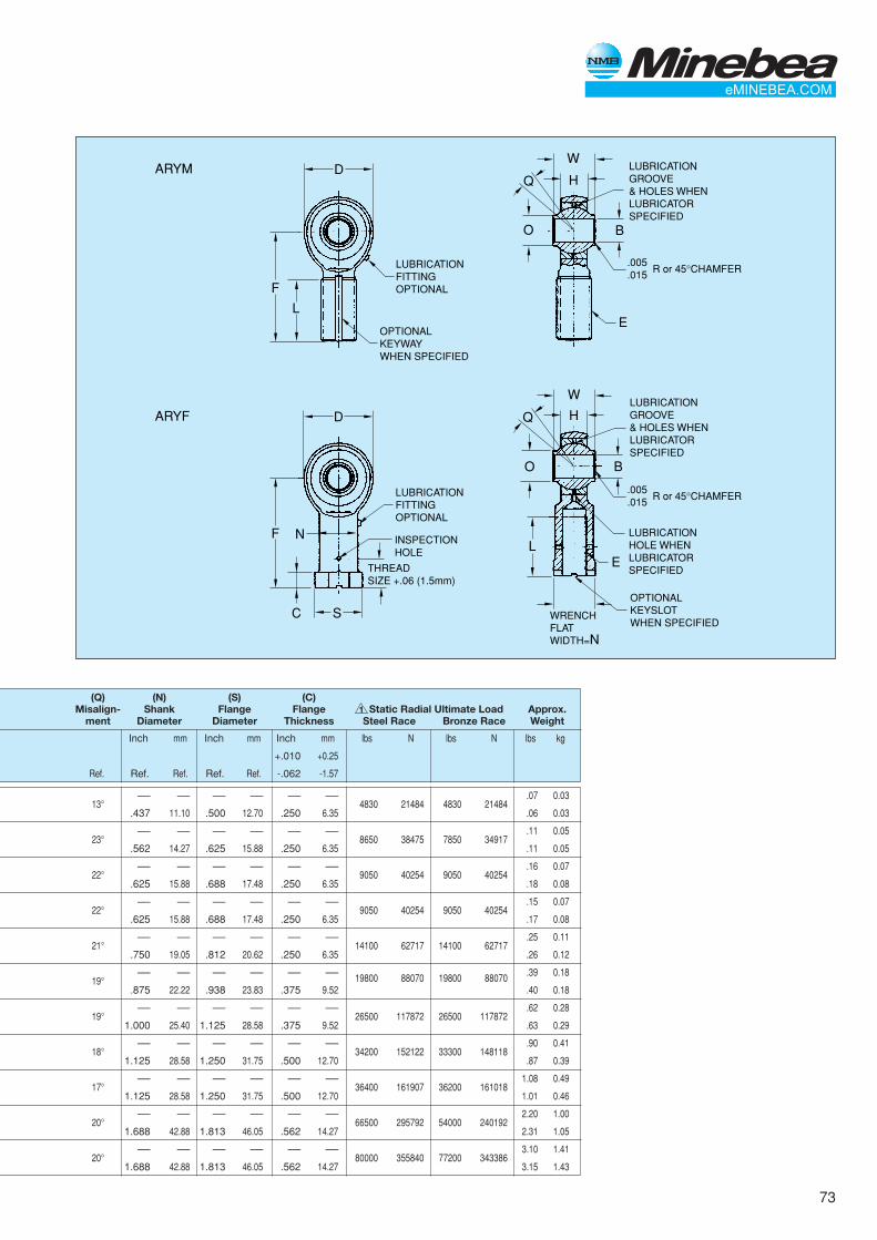
73
D
F
L
W
HQ
O B
E
ARYM
OPTIONALKEYWAYWHEN SPECIFIED
LUBRICATIONFITTINGOPTIONAL
LUBRICATIONGROOVE& HOLES WHENLUBRICATORSPECIFIED
D
FL
N
SC
W
HQ
O B
E
ARYF
INSPECTIONHOLE
THREADSIZE +.06 (1.5mm)
LUBRICATIONFITTINGOPTIONAL
LUBRICATIONGROOVE& HOLES WHENLUBRICATORSPECIFIED
OPTIONALKEYSLOTWHEN SPECIFIED
LUBRICATIONHOLE WHENLUBRICATORSPECIFIED
WRENCHFLATWIDTH=N
.005
.015R or 45°CHAMFER
.005
.015R or 45°CHAMFER
(Q) (N) (S) (C)Misalign- Shank Flange Flange 1 Static Radial Ultimate Load Approx.
ment Diameter Diameter Thickness Steel Race Bronze Race Weight
Inch mm Inch mm Inch mm lbs N lbs N lbs kg
+.010 +0.25
Ref. Ref. Ref. Ref. Ref. -.062 -1.57
13°–— –— –— –— –— –—
4830 21484 4830 21484.07 0.03
.437 11.10 .500 12.70 .250 6.35 .06 0.03
23°–— –— –— –— –— –—
8650 38475 7850 34917.11 0.05
.562 14.27 .625 15.88 .250 6.35 .11 0.05
22°–— –— –— –— –— –—
9050 40254 9050 40254.16 0.07
.625 15.88 .688 17.48 .250 6.35 .18 0.08
22°–— –— –— –— –— –—
9050 40254 9050 40254.15 0.07
.625 15.88 .688 17.48 .250 6.35 .17 0.08
21°–— –— –— –— –— –—
14100 62717 14100 62717.25 0.11
.750 19.05 .812 20.62 .250 6.35 .26 0.12
19°–— –— –— –— –— –— 19800 88070 19800 88070 .39 0.18
.875 22.22 .938 23.83 .375 9.52 .40 0.18
19°–— –— –— –— –— –—
26500 117872 26500 117872.62 0.28
1.000 25.40 1.125 28.58 .375 9.52 .63 0.29
18°–— –— –— –— –— –—
34200 152122 33300 148118.90 0.41
1.125 28.58 1.250 31.75 .500 12.70 .87 0.39
17°–— –— –— –— –— –—
36400 161907 36200 1610181.08 0.49
1.125 28.58 1.250 31.75 .500 12.70 1.01 0.46
20°–— –— –— –— –— –—
66500 295792 54000 2401922.20 1.00
1.688 42.88 1.813 46.05 .562 14.27 2.31 1.05
20°–— –— –— –— –— –—
80000 355840 77200 3433863.10 1.41
1.688 42.88 1.813 46.05 .562 14.27 3.15 1.43
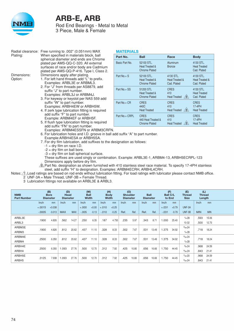
74
ARB-E, ARBRod End Bearings - Metal to Metal3 Piece, Male & Female
Radial clearance: Free running to .002” (0.051mm) MAXPlating: When specified in materials block, ball
spherical diameter and ends are Chromeplated per AMS-QQ-C-320. All externalsurfaces of race and/or body are Cadmiumplated per AMS-QQ-P-416. Type I, Class 2.
Dimensions: Dimensions apply after plating.Option: 1. For left hand threads add “L” to prefix.
Examples: ARBL3E or ARBML3.2. For “J” from threads per AS8879, add
suffix “J” to part number.Examples: ARBL3J or ARBM4J.
3. For keyway or keyslot per NAS 559 addsuffix “W” to part number.Examples: ARBH4EW or ARBH5W.
4. If zerk type lubrication fitting is requiredadd suffix “F” to part number.Example: ARBM4EF or ARBH5F.
5. If flush type lubrication fitting is requiredadd suffix “FN” to part number.Examples: ARBM4ESSFN or ARBM3CRFN.
6. For lubrication holes and I.D. groove in ball add suffix “A” to part number.Example:ARBH4ESA or ARBH5SA.
7. For dry film lubrication, add suffixes to the designation as follows:-1 = dry film on race I.D.-2 = dry film on ball bore.-3 = dry film on ball spherical surface.These suffixes are used singly or combination. Example: ARBL3E-1, ARBM4-13, ARBH5ECRPL-123Dimensions apply before dry film.
8. Part No. designation as shown furnished with 410 stainless steel race material. To specify 17-4PH stainlesssteel, add suffix “H” to designation. Examples: ARBM4ECRH, ARBHL4CRH.
Notes: 1 Load ratings are based on rod ends without lubrication fitting. For load ratings with lubricator please contact NMB office.2 UNF-3A = Male Thread, UNF-3B = Female Thread.3 Lubrication fittings not available on ARBL3E & ARBL3.
(B) (D) (W) (H) (O) (F) (E) (L)NMB Bore Head Ball Body Shoulder Ball Ball C/L Thread ThreadPart Number Diameter Diameter Width Width Diameter Diameter to End Size Length
Inch mm Inch mm Inch mm Inch mm Inch mm Inch mm Inch mm Inch mm
+.0015 +0.038 +.000 +0.00 +.010 +0.25 +.031 +0.79 UNF-3A
-.0005 -0.013 MAX MAX -.005 -0.13 -.010 -0.25 Ref. Ref. Ref. Ref. -.031 -0.79 UNF-3B MIN MIN
ARBL3E.1900 4.826 .562 14.27 .250 6.35 .187 4.750 .235 5.97 .343 8.71 1.000 25.40
1/4-28 .593 15.06
ARBL3 10-32 .500 12.70
ARBM3E.1900 4.826 .812 20.62 .437 11.10 .328 8.33 .302 7.67 .531 13.49 1.375 34.92
5/16-24.718 18.24
ARBM3 1/4-28
ARBM4E.2500 6.350 .812 20.62 .437 11.10 .328 8.33 .302 7.67 .531 13.49 1.375 34.92
5/16-24.718 18.24
ARBM4 1/4-28
ARBH4E.2500 6.350 1.093 27.76 .500 12.70 .312 7.92 .425 10.80 .656 16.66 1.750 44.45
3/8-24 .968 24.59
ARBH4 5/16-24 .843 21.41
ARBH5E.3125 7.938 1.093 27.76 .500 12.70 .312 7.92 .425 10.80 .656 16.66 1.750 44.45
7/16-20 .968 24.59
ARBH5 5/16-24 .843 21.41
MATERIALSPart No. Ball Race Body
Basic Part No. 52100 STL. Aluminum 4130 STL.Heat Treated & Bronze Heat TreatedChrome Plated Cad. Plated
Part No.+ S 52100 STL. 4130 STL. 4130 STL.Heat Treated & Heat Treated & Heat Treated &Chrome Plated Cad. Plated Cad. Plated
Part No.+ SS 51200 STL CRES 4130 STL.Heat Treated & 410 Heat TreatedChrome Plated Heat Treated Cad. Plated
Part No.+ CR CRES CRES CRES440C 410 17-4PHHeat Treated Heat Treated Heat Treated
Part No.+ CRPL CRES CRES CRES440 Heat Treated & 410 17-4PHChrome Plated Heat Treated Heat Treated
8
8
8

75
D
F
L
W
HQ
O B
E
ARB-E
OPTIONALKEYWAYWHEN SPECIFIED
LUBRICATIONFITTINGOPTIONAL
LUBRICATIONGROOVES& HOLES WHENLUBRICATORSPECIFIED
D
FL
N
S.18 (4.6mm)
W
HQ
O B
E
ARB
INSPECTIONHOLE
THREADSIZE +.06 (1.5mm)
LUBRICATIONFITTINGOPTIONAL
LUBRICATIONGROOVE& HOLES WHENLUBRICATORSPECIFIED
OPTIONALKEYSLOTWHEN SPECIFIED
LUBRICATIONHOLE WHENLUBRICATORSPECIFIED
WRENCHFLATWIDTH=N
(Q) (N) (S)Misalign- Shank Flange Static Radial Ultimate Load Approx.
ment Diameter Diameter Steel Race Bronze Race Weight
Inch mm Inch mm lbs N lbs N lbs kg
+.030 +0.76 +.030 +0.76
Ref. -.030 -0.76 -.015 -0.38
13°–— –— –— –— 2750 12232 2750 12232
.02 0.01.281 7.14 .343 8.71 2620 11654 2620 11654
17°–— –— –— –— 6140 27311 6140 27311
.06 0.03.375 9.52 .437 11.10 5230 23263 5230 23263
17°–— –— –— –— 7650 34027 7650 34027
.06 0.03.375 9.52 .437 11.10 5230 23263 5230 23263
21°–— –— –— –— 10650 47371 9900 44035
.13 0.06.500 12.70 .562 14.27 7910 35184 7910 35184
21°–— –— –— –— 14200 63162 9900 44035
.13 0.06.500 12.70 .562 14.27 7910 35184 7910 35184
1
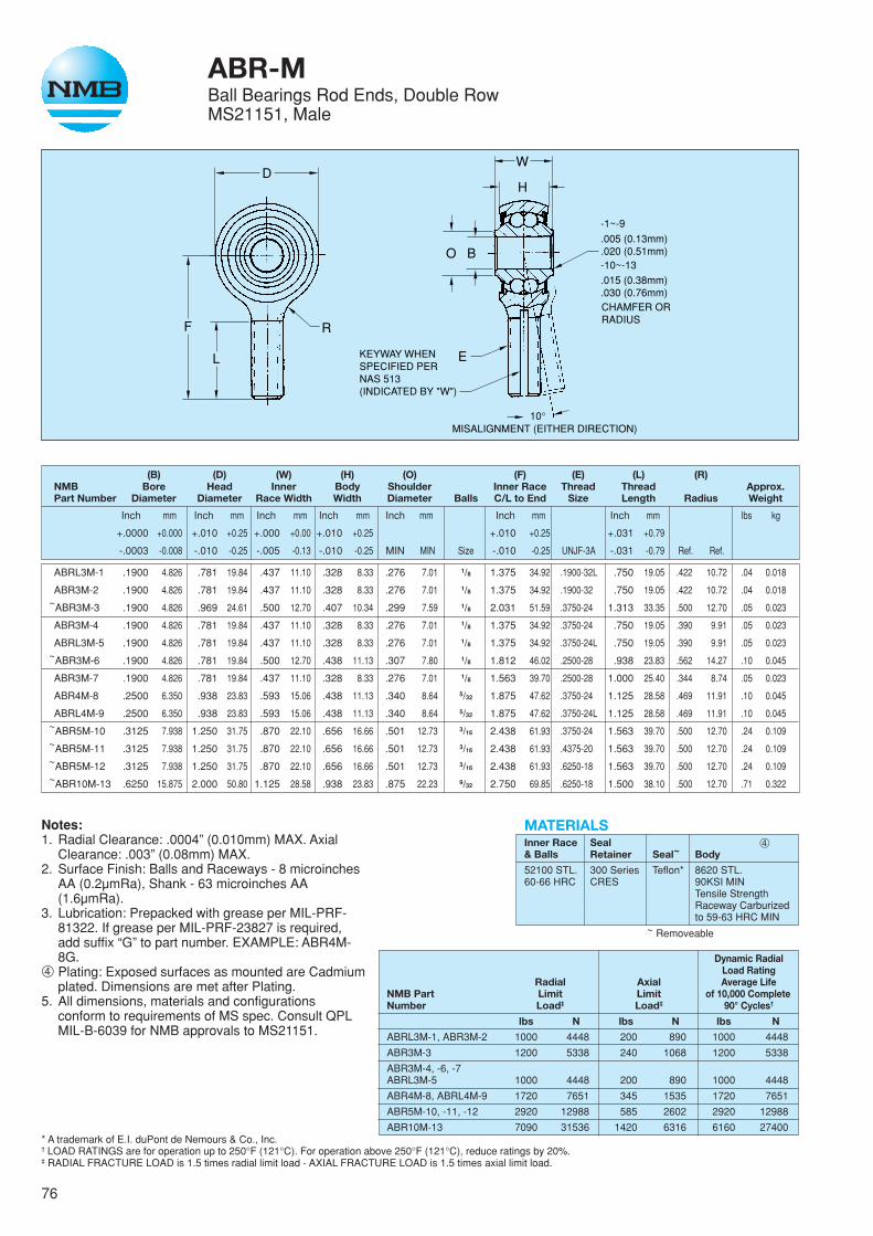
76
ABR-MBall Bearings Rod Ends, Double RowMS21151, Male
D
F
L
R
W
H
O
E
B
KEYWAY WHENSPECIFIED PERNAS 513(INDICATED BY "W")
MISALIGNMENT (EITHER DIRECTION)10°
.005 (0.13mm)
.020 (0.51mm)
-1~-9
-10~-13
CHAMFER ORRADIUS
.015 (0.38mm)
.030 (0.76mm)
(B) (D) (W) (H) (O) (F) (E) (L) (R)NMB Bore Head Inner Body Shoulder Inner Race Thread Thread Approx.Part Number Diameter Diameter Race Width Width Diameter Balls C/L to End Size Length Radius Weight
Inch mm Inch mm Inch mm Inch mm Inch mm Inch mm Inch mm lbs kg
+.0000 +0.000 +.010 +0.25 +.000 +0.00 +.010 +0.25 +.010 +0.25 +.031 +0.79
-.0003 -0.008 -.010 -0.25 -.005 -0.13 -.010 -0.25 MIN MIN Size -.010 -0.25 UNJF-3A -.031 -0.79 Ref. Ref.
ABRL3M-1 .1900 4.826 .781 19.84 .437 11.10 .328 8.33 .276 7.01 1/8 1.375 34.92 .1900-32L .750 19.05 .422 10.72 .04 0.018
ABR3M-2 .1900 4.826 .781 19.84 .437 11.10 .328 8.33 .276 7.01 1/8 1.375 34.92 .1900-32 .750 19.05 .422 10.72 .04 0.018~ABR3M-3 .1900 4.826 .969 24.61 .500 12.70 .407 10.34 .299 7.59 1/8 2.031 51.59 .3750-24 1.313 33.35 .500 12.70 .05 0.023
ABR3M-4 .1900 4.826 .781 19.84 .437 11.10 .328 8.33 .276 7.01 1/8 1.375 34.92 .3750-24 .750 19.05 .390 9.91 .05 0.023
ABRL3M-5 .1900 4.826 .781 19.84 .437 11.10 .328 8.33 .276 7.01 1/8 1.375 34.92 .3750-24L .750 19.05 .390 9.91 .05 0.023~ABR3M-6 .1900 4.826 .781 19.84 .500 12.70 .438 11.13 .307 7.80 1/8 1.812 46.02 .2500-28 .938 23.83 .562 14.27 .10 0.045
ABR3M-7 .1900 4.826 .781 19.84 .437 11.10 .328 8.33 .276 7.01 1/8 1.563 39.70 .2500-28 1.000 25.40 .344 8.74 .05 0.023
ABR4M-8 .2500 6.350 .938 23.83 .593 15.06 .438 11.13 .340 8.64 5/32 1.875 47.62 .3750-24 1.125 28.58 .469 11.91 .10 0.045
ABRL4M-9 .2500 6.350 .938 23.83 .593 15.06 .438 11.13 .340 8.64 5/32 1.875 47.62 .3750-24L 1.125 28.58 .469 11.91 .10 0.045~ABR5M-10 .3125 7.938 1.250 31.75 .870 22.10 .656 16.66 .501 12.73 3/16 2.438 61.93 .3750-24 1.563 39.70 .500 12.70 .24 0.109~ABR5M-11 .3125 7.938 1.250 31.75 .870 22.10 .656 16.66 .501 12.73 3/16 2.438 61.93 .4375-20 1.563 39.70 .500 12.70 .24 0.109~ABR5M-12 .3125 7.938 1.250 31.75 .870 22.10 .656 16.66 .501 12.73 3/16 2.438 61.93 .6250-18 1.563 39.70 .500 12.70 .24 0.109~ABR10M-13 .6250 15.875 2.000 50.80 1.125 28.58 .938 23.83 .875 22.23 9/32 2.750 69.85 .6250-18 1.500 38.10 .500 12.70 .71 0.322
Notes:1. Radial Clearance: .0004” (0.010mm) MAX. Axial
Clearance: .003” (0.08mm) MAX.2. Surface Finish: Balls and Raceways - 8 microinches
AA (0.2µmRa), Shank - 63 microinches AA(1.6µmRa).
3. Lubrication: Prepacked with grease per MIL-PRF-81322. If grease per MIL-PRF-23827 is required,add suffix “G” to part number. EXAMPLE: ABR4M-8G.
➃ Plating: Exposed surfaces as mounted are Cadmiumplated. Dimensions are met after Plating.
5. All dimensions, materials and configurationsconform to requirements of MS spec. Consult QPLMIL-B-6039 for NMB approvals to MS21151.
* A trademark of E.I. duPont de Nemours & Co., Inc.† LOAD RATINGS are for operation up to 250°F (121°C). For operation above 250°F (121°C), reduce ratings by 20%.‡ RADIAL FRACTURE LOAD is 1.5 times radial limit load - AXIAL FRACTURE LOAD is 1.5 times axial limit load.
MATERIALSInner Race Seal ➃& Balls Retainer Seal~ Body
52100 STL. 300 Series Teflon* 8620 STL.60-66 HRC CRES 90KSI MIN
Tensile StrengthRaceway Carburizedto 59-63 HRC MIN
~ Removeable
Dynamic RadialLoad Rating
Radial Axial Average LifeNMB Part Limit Limit of 10,000 CompleteNumber Load‡ Load‡ 90° Cycles†
lbs N lbs N lbs N
ABRL3M-1, ABR3M-2 1000 4448 200 890 1000 4448
ABR3M-3 1200 5338 240 1068 1200 5338
ABR3M-4, -6, -7ABRL3M-5 1000 4448 200 890 1000 4448
ABR4M-8, ABRL4M-9 1720 7651 345 1535 1720 7651
ABR5M-10, -11, -12 2920 12988 585 2602 2920 12988
ABR10M-13 7090 31536 1420 6316 6160 27400

77
ABR-FBall Bearings Rod Ends, Double RowMS21153, Female
DS
FN
G
O B
W
H
ER
MISALIGNMENT(EITHER DIRECTION)
(THREADS ARE "J" FORMPER AS8879, LENGTHINCLUDES MAX OF 2INCOMPLETE THREADS)
KEYSLOT WHENSPECIFIED PER NAS 513(INDICATED BY "W")
10°
.312(7.92mm)
.070 (1.78mm) DIA.INSPECTION HOLE
-1~-9
-10~-13
CHAMFER ORRADIUS
L
.005 (0.13mm)
.020 (0.51mm)
.015 (0.38mm)
.030 (0.76mm)
(B) (D) (W) (H) (O) (F) (E) (L) (N) (R) (S) (G)NMB Bore Head Inner Body Shoulder Length Thread Thread Shank Bead Hex Approx.Part Number Diameter Diameter Race Width Width Diameter Balls C/L to End Size Length Diameter Radius Diameter Diameter Weight
Inch mm Inch mm Inch mm Inch mm Inch mm Inch mm Inch mm Inch mm Inch mm Inch mm Inch mm lbs kg
+.0000+0.000 +.010 +0.25 +.000 +0.00 +.010 +0.25 +.010 +0.25 +.031 +0.79 +.010 +0.25 +0.10 +0.25 +.010 +0.25
-.0003 -0.008 -.010 -0.25 -.005 -0.13 -.010 -0.25 MIN MIN Size -.010 -0.25 UNJF-3B -.031 -0.79 -.010 -0.25 Ref. Ref. -0.10 -0.25 -.010 -0.25
ABR3F-1 .1900 4.826 .781 19.84 .437 11.10 .328 8.33 .276 7.01 1/8 1.375 34.92 .2500-28 .750 19.05 .375 9.52 .390 9.91 .438 11.12 –— –— .05 0.023
ABR3F-2 .1900 4.826 .781 19.84 .437 11.10 .328 8.33 .276 7.01 1/8 1.375 34.92 .3125-24 .750 19.05 .438 11.13 .390 9.91 –— –— .438 11.12 .06 0.027
ABR3F-3 .1900 4.826 .781 19.84 .500 12.70 .328 8.33 .276 7.01 1/8 1.375 34.92 .2500-28 .750 19.05 .375 9.52 .390 9.91 .438 11.12 –— –— .06 0.027
ABRL3F-4 .1900 4.826 .781 19.84 .500 12.70 .328 8.33 .276 7.01 1/8 1.375 34.92 .2500-28L .750 19.05 .375 9.52 .390 9.91 .438 11.12 –— –— .06 0.027
ABRL3F-5 .1900 4.826 .781 19.84 .437 11.10 .328 8.33 .276 7.01 1/8 1.375 34.92 .2500-28L .750 19.05 .375 9.52 .390 9.91 .438 11.12 –— –— .05 0.023
ABR4F-6 .2500 6.350 .938 23.83 .593 15.06 .438 11.13 .340 8.64 5/32 1.469 37.31 .3125-24 .750 19.05 .438 11.13 .468 11.89 –— –— .438 11.12 .07 0.032
ABRL4F-7 .2500 6.350 .938 23.83 .593 15.06 .438 11.13 .340 8.64 5/32 1.469 37.31 .3125-24L .750 19.05 .438 11.13 .468 11.89 –— –— .438 11.12 .07 0.032
ABR4F-8 .2500 6.350 .938 23.83 .593 15.06 .438 11.13 .340 8.64 5/32 1.875 47.62 .4375-20 1.125 28.58 .625 15.88 .468 11.89 –— –— –— –— .16 0.072
ABRL4F-9 .2500 6.350 .938 23.83 .593 15.06 .438 11.13 .340 8.64 5/32 1.875 47.62 .4375-20L 1.125 28.58 .625 15.88 .468 11.89 –— –— –— –— .16 0.072
~ABR5F-10 .3125 7.938 1.250 31.75 .870 22.10 .656 16.66 .501 12.73 3/16 1.875 47.62 .3125-24 1.000 25.40 .438 11.12 .500 12.70 –— –— –— –— .10 0.045
~ABRL5F-11 .3125 7.938 1.250 31.75 .870 22.10 .656 16.66 .501 12.73 3/16 1.875 47.62 .3125-24L 1.000 25.40 .438 11.12 .500 12.70 –— –— –— –— .10 0.045
Notes:1. Radial Clearance: .0004” (0.010mm) MAX. Axial
Clearance: .003” (0.08mm) MAX.2. Surface Finish: Balls and Raceways - 8 microinches
AA (0.2µmRa), Shank - 63 microinches AA(1.6µmRa).
3. Lubrication: Prepacked with grease per MIL-PRF-81322. If grease per MIL-PRF-23827 is required,add suffix “G” to part number. EXAMPLE: ABR4M-8G.
➃ Plating: Exposed surfaces as mounted are Cadmiumplated. Dimensions are met after Plating.
5. All dimensions, materials and configurationsconform to requirements of MS spec. Consult QPLAS6039 for NMB approvals to MS21153.
* A trademark of E.I. duPont de Nemours & Co., Inc.† LOAD RATINGS are for operation up to 250°F (121°C). For operation above 250°F (121°C), reduce ratings by 20%.‡ RADIAL FRACTURE LOAD is 1.5 times radial limit load - AXIAL FRACTURE LOAD is 1.5 times axial limit load.
Dynamic RadialLoad Rating
NMB Radial Axial Average LifePart Limit Limit of 10,000 CompleteNumber Load‡ Load‡ 90° Cycles†
lbs N lbs N lbs N
ABR3F-1, -2, -3 1000 4448 200 890 1000 4448ABRL3F-4, -5
ABR4F-6, -8 1720 7651 345 1535 1720 7651ABRL4F-7, -9
ABR5F-10 2920 12988 585 2602 2920 12988ABRL5F-11
MATERIALSInner Race Seal ➃& Balls Retainer Seal~ Body
52100 STL. 300 Series Teflon* 8620 STL.60-66 HRC CRES 90KSI MIN
Tensile StrengthRaceway Carburizedto 59-63 HRC MIN
~ Removeable
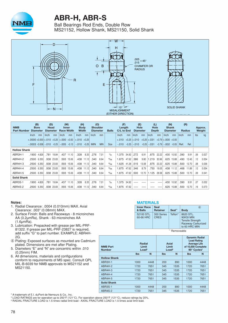
78
ABR-H, ABR-SBall Bearings Rod Ends, Double RowMS21152, Hollow Shank, MS21150, Solid Shank
* A trademark of E.I. duPont de Nemours & Co., Inc.† LOAD RATINGS are for operation up to 250°F (121°C). For operation above 250°F (121°C), reduce ratings by 20%.‡ RADIAL FRACTURE LOAD is 1.5 times radial limit load - AXIAL FRACTURE LOAD is 1.5 times axial limit load.
D
F
O B
W
H
ER
MISALIGNMENT(EITHER DIRECTION)
SOLID SHANK10°
CHAMFER ORRADIUS
L
.005
.015 45°✕
N
(B) (D) (W) (H) (O) (F) (E) (L) (N) (R)NMB Bore Head Inner Body Shoulder Length Hole Hole Shank Approx.Part Number Diameter Diameter Race Width Width Diameter Balls C/L to End Diameter Depth Diameter Radius Weight
Inch mm Inch mm Inch mm Inch mm Inch mm Inch mm Inch mm Inch mm Inch mm Inch mm lbs kg
+.0000 +0.000 +.010 +0.25 +.000 +0.00 +.010 +0.25 +.010 +0.25 +.010 +0.25 +.031 +0.79 +.000 +0.00
-.0003 -0.008 -.010 -0.25 -.005 -0.13 -.010 -0.25 MIN MIN Size -.010 -0.25 -.010 -0.25 -.031 -0.79 -.002 -0.05 Ref. Ref.
Hollow Shank
ABR3H-1 .1900 4.826 .781 19.84 .437 11.10 .328 8.33 .276 7.01 1/8 1.375 34.92 .272 6.91 .875 22.22 .430 10.92 .390 9.91 .06 0.027
ABR4H-2 .2500 6.350 .938 23.83 .593 15.06 .438 11.12 .340 8.64 5/32 1.875 47.62 .386 9.80 1.219 30.96 .625 15.88 .490 12.45 .12 0.054
ABR4H-3 .2500 6.350 .938 23.83 .593 15.06 .438 11.12 .340 8.64 5/32 1.625 41.28 .515 13.08 .875 22.22 .625 15.88 .500 12.70 .08 0.036
ABR4H-4 .2500 6.350 .938 23.83 .593 15.06 .438 11.12 .340 8.64 5/32 1.875 47.62 .346 8.79 .750 19.05 .438 11.12 .468 11.89 .12 0.054
ABR4H-5 .2500 6.350 .938 23.83 .593 15.06 .438 11.12 .340 8.64 5/32 1.875 47.62 .500 12.70 1.125 28.58 .625 15.88 .500 12.70 .09 0.041
Solid Shank
ABR3S-1 .1900 4.826 .781 19.84 .437 11.10 .328 8.33 .276 7.01 1/8 1.375 34.92 –— –— –— –— .430 10.92 .390 9.91 .07 0.032
ABR4S-2 .2500 6.350 .938 23.83 .593 15.06 .438 11.12 .340 8.64 5/32 1.875 47.62 –— –— –— –— .625 15.88 .500 12.70 .16 0.073
Notes:1. Radial Clearance: .0004 (0.010mm) MAX. Axial
Clearance: .003” (0.08mm) MAX.2. Surface Finish: Balls and Raceways - 8 microinches
AA (0.2µmRa), Shank - 63 microinches AA(1.6µmRa).
3. Lubrication: Prepacked with grease per MIL-PRF-81322. If grease per MIL-PRF-23827 is required,add suffix “G” to part number. EXAMPLE: ABR4H-2G.
➃ Plating: Exposed surfaces as mounted are Cadmiumplated. Dimensions are met after Plating.
5. Diameters “E” and “N” are concentric within .010(0.25mm) FIM.
6. All dimensions, materials and configurationsconform to requirements of MS spec. Consult QPLMIL-B-6039 for NMB approvals to MS21152 andMS21150.
Dynamic RadialLoad Rating
Radial Axial Average LifeNMB Part Limit Limit of 10,000 CompleteNumber Load‡ Load‡ 90° Cycles†
lbs N lbs N lbs N
Hollow Shank
ABR3H-1 1000 4448 200 890 1000 4448
ABR4H-2 1720 7651 345 1535 1720 7651
ABR4H-3 1720 7651 345 1535 1720 7651
ABR4H-4 1720 7651 345 1535 1720 7651
ABR4H-5 1720 7651 345 1535 1720 7651
Solid Shank
ABR3S-1 1000 4448 200 890 1000 4448
ABR4S-2 1720 7651 345 1535 1720 7651
MATERIALSInner Race Seal ➃& Balls Retainer Seal~ Body
52100 STL. 300 Series Teflon* 8620 STL.60-66 HRC CRES 90KSI MIN
Tensile StrengthRaceway Carburizedto 60 HRC MIN
~ Removeable
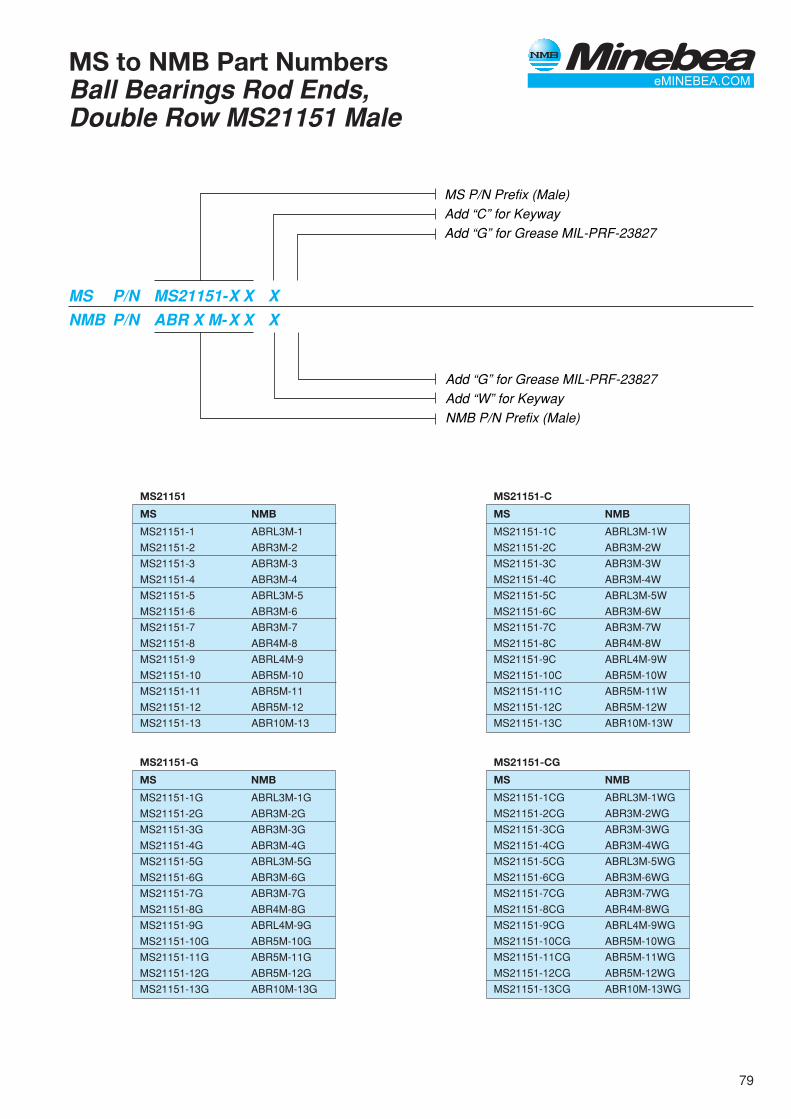
79
MS to NMB Part NumbersBall Bearings Rod Ends,Double Row MS21151 Male
MS P/N Prefix (Male)Add “C” for KeywayAdd “G” for Grease MIL-PRF-23827
MS P/N MS21151-X X XNMB P/N ABR X M-X X X
Add “G” for Grease MIL-PRF-23827Add “W” for KeywayNMB P/N Prefix (Male)
MS21151
MS NMB
MS21151-1 ABRL3M-1
MS21151-2 ABR3M-2
MS21151-3 ABR3M-3
MS21151-4 ABR3M-4
MS21151-5 ABRL3M-5
MS21151-6 ABR3M-6
MS21151-7 ABR3M-7
MS21151-8 ABR4M-8
MS21151-9 ABRL4M-9
MS21151-10 ABR5M-10
MS21151-11 ABR5M-11
MS21151-12 ABR5M-12
MS21151-13 ABR10M-13
MS21151-CG
MS NMB
MS21151-1CG ABRL3M-1WG
MS21151-2CG ABR3M-2WG
MS21151-3CG ABR3M-3WG
MS21151-4CG ABR3M-4WG
MS21151-5CG ABRL3M-5WG
MS21151-6CG ABR3M-6WG
MS21151-7CG ABR3M-7WG
MS21151-8CG ABR4M-8WG
MS21151-9CG ABRL4M-9WG
MS21151-10CG ABR5M-10WG
MS21151-11CG ABR5M-11WG
MS21151-12CG ABR5M-12WG
MS21151-13CG ABR10M-13WG
MS21151-C
MS NMB
MS21151-1C ABRL3M-1W
MS21151-2C ABR3M-2W
MS21151-3C ABR3M-3W
MS21151-4C ABR3M-4W
MS21151-5C ABRL3M-5W
MS21151-6C ABR3M-6W
MS21151-7C ABR3M-7W
MS21151-8C ABR4M-8W
MS21151-9C ABRL4M-9W
MS21151-10C ABR5M-10W
MS21151-11C ABR5M-11W
MS21151-12C ABR5M-12W
MS21151-13C ABR10M-13W
MS21151-G
MS NMB
MS21151-1G ABRL3M-1G
MS21151-2G ABR3M-2G
MS21151-3G ABR3M-3G
MS21151-4G ABR3M-4G
MS21151-5G ABRL3M-5G
MS21151-6G ABR3M-6G
MS21151-7G ABR3M-7G
MS21151-8G ABR4M-8G
MS21151-9G ABRL4M-9G
MS21151-10G ABR5M-10G
MS21151-11G ABR5M-11G
MS21151-12G ABR5M-12G
MS21151-13G ABR10M-13G
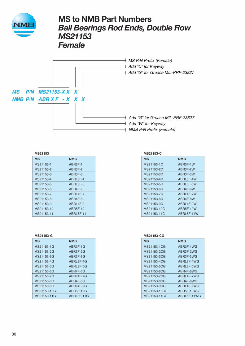
80
MS21153
MS NMB
MS21153-1 ABR3F-1
MS21153-2 ABR3F-2
MS21153-3 ABR3F-3
MS21153-4 ABRL3F-4
MS21153-5 ABRL3F-5
MS21153-6 ABR4F-6
MS21153-7 ABRL4F-7
MS21153-8 ABR4F-8
MS21153-9 ABRL4F-9
MS21153-10 ABR5F-10
MS21153-11 ABRL5F-11
MS to NMB Part NumbersBall Bearings Rod Ends, Double RowMS21153Female
MS P/N Prefix (Female)Add “C” for KeywayAdd “G” for Grease MIL-PRF-23827
MS P/N MS21153-X X XNMB P/N ABR X F - X X X
Add “G” for Grease MIL-PRF-23827Add “W” for KeywayNMB P/N Prefix (Female)
MS21153-CG
MS NMB
MS21153-1CG ABR3F-1WG
MS21153-2CG ABR3F-2WG
MS21153-3CG ABR3F-3WG
MS21153-4CG ABRL3F-4WG
MS21153-5CG ABRL3F-5WG
MS21153-6CG ABR4F-6WG
MS21153-7CG ABRL4F-7WG
MS21153-8CG ABR4F-8WG
MS21153-9CG ABRL4F-9WG
MS21153-10CG ABR5F-10WG
MS21153-11CG ABRL5F-11WG
MS21153-G
MS NMB
MS21153-1G ABR3F-1G
MS21153-2G ABR3F-2G
MS21153-3G ABR3F-3G
MS21153-4G ABRL3F-4G
MS21153-5G ABRL3F-5G
MS21153-6G ABR4F-6G
MS21153-7G ABRL4F-7G
MS21153-8G ABR4F-8G
MS21153-9G ABRL4F-9G
MS21153-10G ABR5F-10G
MS21153-11G ABRL5F-11G
MS21153-C
MS NMB
MS21153-1C ABR3F-1W
MS21153-2C ABR3F-2W
MS21153-3C ABR3F-3W
MS21153-4C ABRL3F-4W
MS21153-5C ABRL3F-5W
MS21153-6C ABR4F-6W
MS21153-7C ABRL4F-7W
MS21153-8C ABR4F-8W
MS21153-9C ABRL4F-9W
MS21153-10C ABR5F-10W
MS21153-11C ABRL5F-11W
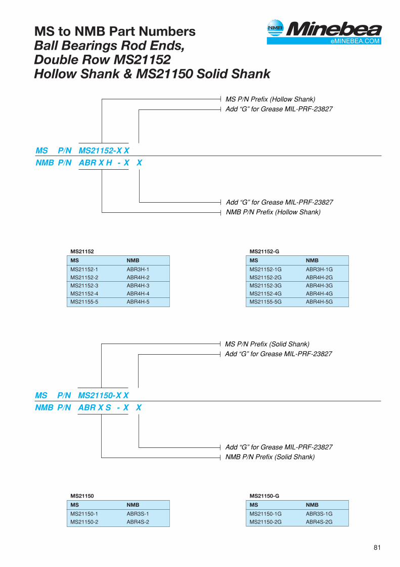
81
MS to NMB Part NumbersBall Bearings Rod Ends,Double Row MS21152Hollow Shank & MS21150 Solid Shank
MS P/N Prefix (Hollow Shank)Add “G” for Grease MIL-PRF-23827
MS P/N MS21152-X XNMB P/N ABR X H - X X
Add “G” for Grease MIL-PRF-23827NMB P/N Prefix (Hollow Shank)
MS P/N Prefix (Solid Shank)Add “G” for Grease MIL-PRF-23827
MS P/N MS21150-X XNMB P/N ABR X S - X X
Add “G” for Grease MIL-PRF-23827NMB P/N Prefix (Solid Shank)
MS21152-G
MS NMB
MS21152-1G ABR3H-1G
MS21152-2G ABR4H-2G
MS21152-3G ABR4H-3G
MS21152-4G ABR4H-4G
MS21155-5G ABR4H-5G
MS21152
MS NMB
MS21152-1 ABR3H-1
MS21152-2 ABR4H-2
MS21152-3 ABR4H-3
MS21152-4 ABR4H-4
MS21155-5 ABR4H-5
MS21150-G
MS NMB
MS21150-1G ABR3S-1G
MS21150-2G ABR4S-2G
MS21150
MS NMB
MS21150-1 ABR3S-1
MS21150-2 ABR4S-2

82
AJ-A, AJ-CJournal, Plain - Teflon Lined**MS21240
Temperature: Operating temperature range -65° to 250°F.(-54° to 121°C)
Concentricity tolerance between B and D diameters shall notexceed .003” (0.08mm) FIM
MATERIALSMaterial Code Journal Liner
AJ-A Aluminum Alloy *Teflon/FabricAMS-QQ-A-225/9 or Bonded to boreAMS-QQ-A-200/11. Finish no lub. requied.Anodized per MIL-A-8625,
AJ-C CRES 410 *Teflon/FabricH.T. to 27-32 HRC Bonded to bore
no lub. requied.
Shaft and Housing InformationFor optimum performance with lined journal bearings, consid-erable care must be exercised in the design of housings andshafts. For extreme applications involving dissimilar materials,elevated temperatures, or extreme loads, contact NMBEngineering for application recommendations. The adjacenttable applies to normal conditions.
* A trademark of E.I. duPont de Nemours & Co., Inc.** MIL-B-8943 (MS21240) was superseded to AS81934/1
Shaft Housing
Diameter B -.0010” (0.025mm) D -.0006” (0.015mm)to -.0020” (0.051mm) to -.0011” (0.028mm)
Taper and Not to Not toRoundness exceed .0005” (0.013mm) exceed .0005" (0.013mm)
Finish 8 RHR (0.2µmRa)Polishedor honedafter grind
Hardness 50 HRC MIN
(B) (D) Weight Lbs./In. (Ref.)Bore Diameter Outside Diameter L = 1,000 (25.4mm)
NMB Part Number ALUM. CRES ALUM. CRES
Inch mm Inch mm Inch mm lb/in g/mm lb/in g/mm
MS21240 +.0000 +0.000 +.0005 +0.013 +.0000 +0.000
Plain -.0010 -0.025 -.0005 -0.013 -.0005 -0.013
AJ04 .2515 6.388 .3760 9.550 .3760 9.550 .006 0.11 .017 0.30
AJ05 .3140 7.976 .4386 11.140 .4386 11.140 .008 0.14 .022 0.39
AJ06 .3765 9.563 .5012 12.730 .5012 12.730 .009 0.16 .025 0.45
AJ07 .4390 11.151 .5638 14.321 .5638 14.321 .010 0.18 .028 0.50
AJ08 .5015 12.738 .6265 15.913 .6265 15.913 .011 0.20 .031 0.55
AJ09 .5640 12.326 .6892 17.506 .6892 17.506 .013 0.23 .036 0.64
AJ10 .6265 15.913 .8142 20.681 .8142 20.681 .022 0.39 .061 1.09
AJ11 .6890 17.501 .8767 22.268 .8767 22.268 .023 0.41 .064 1.14
AJ12 .7515 19.088 .9393 23.858 .9393 23.858 .025 0.45 .070 1.25
AJ14 .8765 22.263 1.0645 27.038 1.0645 27.038 .029 0.52 .080 1.43
AJ16 1.0015 25.438 1.1898 30.221 1.1898 30.221 .033 0.59 .091 1.63
AJ18 1.1265 28.613 1.3148 33.396 1.3148 33.396 .037 0.66 .101 1.80
AJ20 1.2515 31.788 1.4398 36.571 1.4398 36.571 .040 0.71 .111 1.98
AJ22 1.3765 34.963 1.5648 39.746 1.5648 39.746 .044 0.79 .122 2.18
AJ24 1.5015 38.138 1.7523 44.508 1.7523 44.508 .065 1.16 .179 3.20
AJ26 1.6265 41.313 1.8773 47.638 1.8773 47.683 .070 1.25 .193 3.45
AJ28 1.7515 44.488 2.0023 50.858 2.0023 50.858 .075 1.34 .207 3.70
AJ32 2.0015 50.838 2.2523 57.208 2.2523 57.206 .085 1.52 .234 4.18
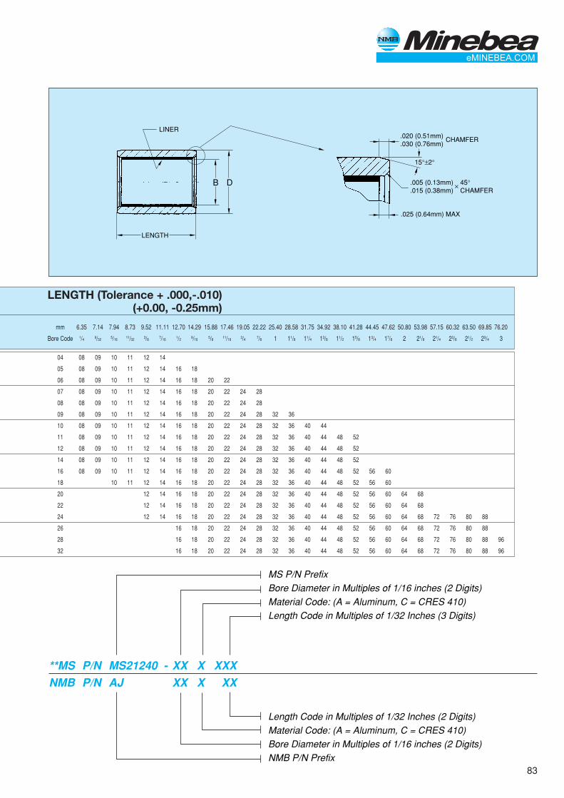
83
mm 6.35 7.14 7.94 8.73 9.52 11.11 12.70 14.29 15.88 17.46 19.05 22.22 25.40 28.58 31.75 34.92 38.10 41.28 44.45 47.62 50.80 53.98 57.15 60.32 63.50 69.85 76.20
Bore Code 1/4 9/32 5/16 11/32 3/8 7/16 1/2 9/16 5/8 11/16 3/4 7/8 1 11/8 11/4 13/8 11/2 15/8 13/4 17/8 2 21/8 21/4 23/8 21/2 23/4 3
.020 (0.51mm)
.030 (0.76mm)CHAMFER
LINER
LENGTH
B D .005 (0.13mm).015 (0.38mm)
.025 (0.64mm) MAX
45°CHAMFER
✕
15°±2°
MS P/N PrefixBore Diameter in Multiples of 1/16 inches (2 Digits)Material Code: (A = Aluminum, C = CRES 410)Length Code in Multiples of 1/32 Inches (3 Digits)
Length Code in Multiples of 1/32 Inches (2 Digits)Material Code: (A = Aluminum, C = CRES 410)Bore Diameter in Multiples of 1/16 inches (2 Digits)NMB P/N Prefix
**MS P/N MS21240 - XX X XXXNMB P/N AJ XX X XX
LENGTH (Tolerance + .000,-.010)(+0.00, -0.25mm)
04 08 09 10 11 12 14
05 08 09 10 11 12 14 16 18
06 08 09 10 11 12 14 16 18 20 22
07 08 09 10 11 12 14 16 18 20 22 24 28
08 08 09 10 11 12 14 16 18 20 22 24 28
09 08 09 10 11 12 14 16 18 20 22 24 28 32 36
10 08 09 10 11 12 14 16 18 20 22 24 28 32 36 40 44
11 08 09 10 11 12 14 16 18 20 22 24 28 32 36 40 44 48 52
12 08 09 10 11 12 14 16 18 20 22 24 28 32 36 40 44 48 52
14 08 09 10 11 12 14 16 18 20 22 24 28 32 36 40 44 48 52
16 08 09 10 11 12 14 16 18 20 22 24 28 32 36 40 44 48 52 56 60
18 10 11 12 14 16 18 20 22 24 28 32 36 40 44 48 52 56 60
20 12 14 16 18 20 22 24 28 32 36 40 44 48 52 56 60 64 68
22 12 14 16 18 20 22 24 28 32 36 40 44 48 52 56 60 64 68
24 12 14 16 18 20 22 24 28 32 36 40 44 48 52 56 60 64 68 72 76 80 88
26 16 18 20 22 24 28 32 36 40 44 48 52 56 60 64 68 72 76 80 88
28 16 18 20 22 24 28 32 36 40 44 48 52 56 60 64 68 72 76 80 88 96
32 16 18 20 22 24 28 32 36 40 44 48 52 56 60 64 68 72 76 80 88 96
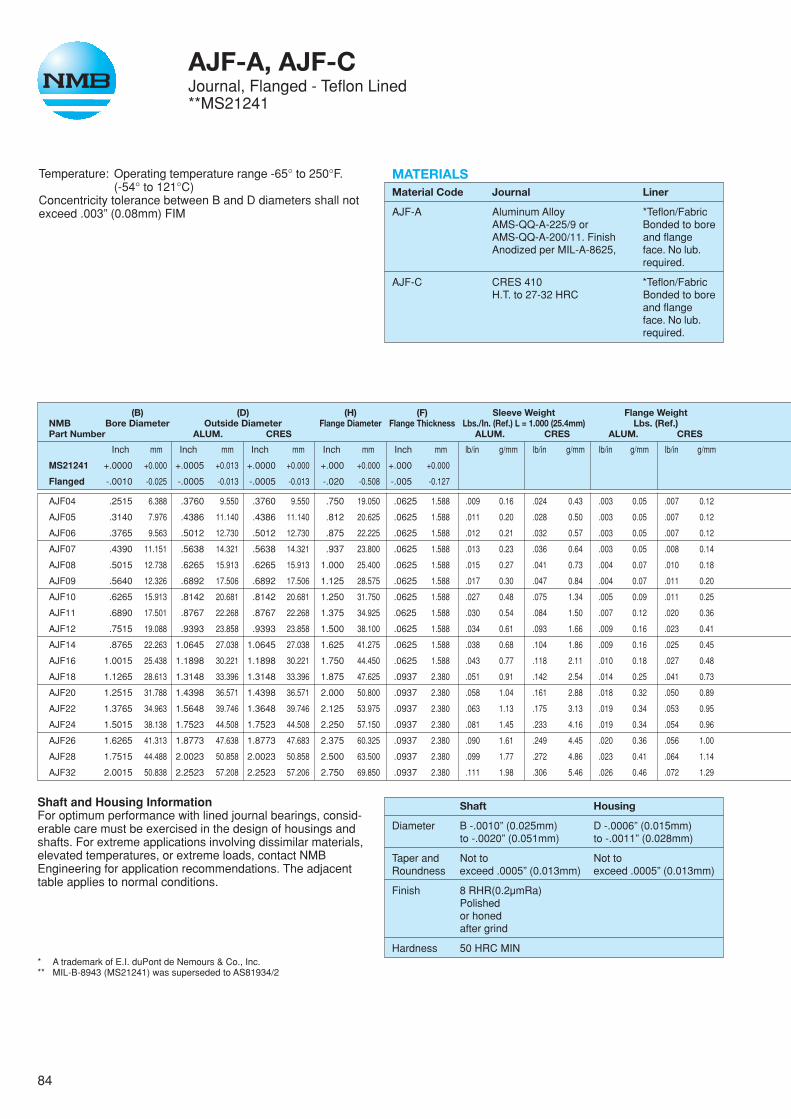
84
AJF-A, AJF-CJournal, Flanged - Teflon Lined**MS21241
Temperature: Operating temperature range -65° to 250°F.(-54° to 121°C)
Concentricity tolerance between B and D diameters shall notexceed .003” (0.08mm) FIM
Shaft and Housing InformationFor optimum performance with lined journal bearings, consid-erable care must be exercised in the design of housings andshafts. For extreme applications involving dissimilar materials,elevated temperatures, or extreme loads, contact NMBEngineering for application recommendations. The adjacenttable applies to normal conditions.
* A trademark of E.I. duPont de Nemours & Co., Inc.** MIL-B-8943 (MS21241) was superseded to AS81934/2
Shaft Housing
Diameter B -.0010” (0.025mm) D -.0006” (0.015mm)to -.0020” (0.051mm) to -.0011” (0.028mm)
Taper and Not to Not toRoundness exceed .0005” (0.013mm) exceed .0005” (0.013mm)
Finish 8 RHR(0.2µmRa)Polishedor honedafter grind
Hardness 50 HRC MIN
lb/in g/mm lb/in g/mm lb/in g/mm
.024 0.43 .003 0.05 .007 0.12
.028 0.50 .003 0.05 .007 0.12
.032 0.57 .003 0.05 .007 0.12
.036 0.64 .003 0.05 .008 0.14
.041 0.73 .004 0.07 .010 0.18
.047 0.84 .004 0.07 .011 0.20
.075 1.34 .005 0.09 .011 0.25
.084 1.50 .007 0.12 .020 0.36
.093 1.66 .009 0.16 .023 0.41
.104 1.86 .009 0.16 .025 0.45
.118 2.11 .010 0.18 .027 0.48
.142 2.54 .014 0.25 .041 0.73
.161 2.88 .018 0.32 .050 0.89
.175 3.13 .019 0.34 .053 0.95
.233 4.16 .019 0.34 .054 0.96
.249 4.45 .020 0.36 .056 1.00
.272 4.86 .023 0.41 .064 1.14
.306 5.46 .026 0.46 .072 1.29
MATERIALSMaterial Code Journal Liner
AJF-A Aluminum Alloy *Teflon/FabricAMS-QQ-A-225/9 or Bonded to boreAMS-QQ-A-200/11. Finish and flangeAnodized per MIL-A-8625, face. No lub.
required.
AJF-C CRES 410 *Teflon/FabricH.T. to 27-32 HRC Bonded to bore
and flangeface. No lub.required.
(B) (D) (H) (F) Sleeve Weight Flange WeightNMB Bore Diameter Outside Diameter Flange Diameter Flange Thickness Lbs./In. (Ref.) L = 1.000 (25.4mm) Lbs. (Ref.)Part Number ALUM. CRES ALUM. CRES ALUM. CRES
Inch mm Inch mm Inch mm Inch mm Inch mm lb/in g/mm
MS21241 +.0000 +0.000 +.0005 +0.013 +.0000 +0.000 +.000 +0.000 +.000 +0.000
Flanged -.0010 -0.025 -.0005 -0.013 -.0005 -0.013 -.020 -0.508 -.005 -0.127
AJF04 .2515 6.388 .3760 9.550 .3760 9.550 .750 19.050 .0625 1.588 .009 0.16
AJF05 .3140 7.976 .4386 11.140 .4386 11.140 .812 20.625 .0625 1.588 .011 0.20
AJF06 .3765 9.563 .5012 12.730 .5012 12.730 .875 22.225 .0625 1.588 .012 0.21
AJF07 .4390 11.151 .5638 14.321 .5638 14.321 .937 23.800 .0625 1.588 .013 0.23
AJF08 .5015 12.738 .6265 15.913 .6265 15.913 1.000 25.400 .0625 1.588 .015 0.27
AJF09 .5640 12.326 .6892 17.506 .6892 17.506 1.125 28.575 .0625 1.588 .017 0.30
AJF10 .6265 15.913 .8142 20.681 .8142 20.681 1.250 31.750 .0625 1.588 .027 0.48
AJF11 .6890 17.501 .8767 22.268 .8767 22.268 1.375 34.925 .0625 1.588 .030 0.54
AJF12 .7515 19.088 .9393 23.858 .9393 23.858 1.500 38.100 .0625 1.588 .034 0.61
AJF14 .8765 22.263 1.0645 27.038 1.0645 27.038 1.625 41.275 .0625 1.588 .038 0.68
AJF16 1.0015 25.438 1.1898 30.221 1.1898 30.221 1.750 44.450 .0625 1.588 .043 0.77
AJF18 1.1265 28.613 1.3148 33.396 1.3148 33.396 1.875 47.625 .0937 2.380 .051 0.91
AJF20 1.2515 31.788 1.4398 36.571 1.4398 36.571 2.000 50.800 .0937 2.380 .058 1.04
AJF22 1.3765 34.963 1.5648 39.746 1.3648 39.746 2.125 53.975 .0937 2.380 .063 1.13
AJF24 1.5015 38.138 1.7523 44.508 1.7523 44.508 2.250 57.150 .0937 2.380 .081 1.45
AJF26 1.6265 41.313 1.8773 47.638 1.8773 47.683 2.375 60.325 .0937 2.380 .090 1.61
AJF28 1.7515 44.488 2.0023 50.858 2.0023 50.858 2.500 63.500 .0937 2.380 .099 1.77
AJF32 2.0015 50.838 2.2523 57.208 2.2523 57.206 2.750 69.850 .0937 2.380 .111 1.98

85
mm 6.35 7.14 7.94 8.73 9.52 11.11 12.70 14.29 15.88 17.46 19.05 22.22 25.40 28.58 31.75 34.92 38.10 41.28 44.45 47.62 50.80 53.98 57.14 60.32 63.05 69.85 76.20
Bore Code 1/4 9/32 5/16 11/32 3/8 7/16 1/2 9/16 5/8 11/16 3/4 7/8 1 11/8 11/4 13/8 11/2 15/8 13/4 17/8 2 21/8 21/4 23/8 21/2 23/4 3
.062 (1.57mm) MAX
.020 (0.51mm) MAX
.020 (0.51mm) MAX .005 (0.13mm)MAX UNDERCUT
CHAMFER
LENGTH
LINERS
B D
.030 (0.76mm)
.020 (0.51mm)CHAMFEROR RAD
.020 (0.51mm)
.030 (0.76mm)
.055 (1.40mm) MAX.
.025 (0.64mm) MAX
45°✕
.005 (0.13mm)
.015 (0.38mm)CHAMFER OR RAD
45°✕
15°±2°
F
F
HB+.100(2.54mm)MAX.
MS P/N PrefixBore Diameter in Multiples of 1/16 inches (2 Digits)Material Code: (A = Aluminum, C = CRES 410)Length Code in Multiples of 1/32 Inches (3 Digits)
Length Code in Multiples of 1/32 Inches (2 Digits)Material Code: (A = Aluminum, C = CRES 410)Bore Diameter in Multiples of 1/16 inches (2 Digits)NMB P/N Prefix
**MS P/N MS21241 - XX X XXXNMB P/N AJ XX X XX
LENGTH (Tolerance + .000,-.010)(+0.00, -0.25mm)
04 08 09 10 11 12 14
05 08 09 10 11 12 14 16 18
06 08 09 10 11 12 14 16 18 20 22
07 08 09 10 11 12 14 16 18 20 22 24 28
08 08 09 10 11 12 14 16 18 20 22 24 28
09 08 09 10 11 12 14 16 18 20 22 24 28 32 36
10 08 09 10 11 12 14 16 18 20 22 24 28 32 36 40 44
11 08 09 10 11 12 14 16 18 20 22 24 28 32 36 40 44 48 52
12 08 09 10 11 12 14 16 18 20 22 24 28 32 36 40 44 48 52
14 08 09 10 11 12 14 16 18 20 22 24 28 32 36 40 44 48 52
16 08 09 10 11 12 14 16 18 20 22 24 28 32 36 40 44 48 52 56 60
18 10 11 12 14 16 18 20 22 24 28 32 36 40 44 48 52 56 60
20 12 14 16 18 20 22 24 28 32 36 40 44 48 52 56 60 64 68
22 12 14 16 18 20 22 24 28 32 36 40 44 48 52 56 60 64 68
24 12 14 16 18 20 22 24 28 32 36 40 44 48 52 56 60 64 68 72 76 80 88
26 16 18 20 22 24 28 32 36 40 44 48 52 56 60 64 68 72 76 80 88 96
28 16 18 20 22 24 28 32 36 40 44 48 52 56 60 64 68 72 76 80 88 96
32 16 18 20 22 24 28 32 36 40 44 48 52 56 60 64 68 72 76 80 88 96
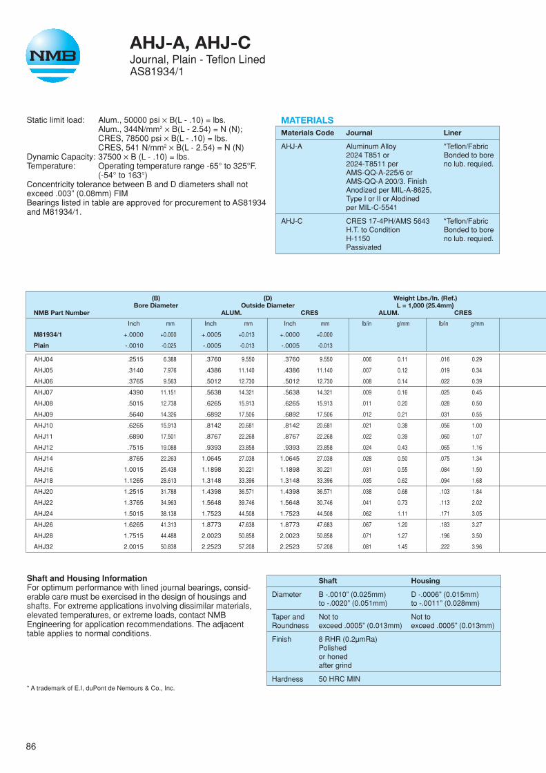
86
AHJ-A, AHJ-CJournal, Plain - Teflon LinedAS81934/1
Static limit load: Alum., 50000 psi ✕ B(L - .10) = lbs.Alum., 344N/mm2 ✕ B(L - 2.54) = N (N);CRES, 78500 psi ✕ B(L - .10) = lbs.CRES, 541 N/mm2 ✕ B(L - 2.54) = N (N)
Dynamic Capacity: 37500 ✕ B (L - .10) = lbs.Temperature: Operating temperature range -65° to 325°F.
(-54° to 163°)Concentricity tolerance between B and D diameters shall notexceed .003” (0.08mm) FIMBearings listed in table are approved for procurement to AS81934and M81934/1.
MATERIALSMaterials Code Journal Liner
AHJ-A Aluminum Alloy *Teflon/Fabric2024 T851 or Bonded to bore2024-T8511 per no lub. requied.AMS-QQ-A-225/6 orAMS-QQ-A 200/3. FinishAnodized per MIL-A-8625,Type I or II or Alodinedper MIL-C-5541
AHJ-C CRES 17-4PH/AMS 5643 *Teflon/FabricH.T. to Condition Bonded to boreH-1150 no lub. requied.Passivated
Shaft and Housing InformationFor optimum performance with lined journal bearings, consid-erable care must be exercised in the design of housings andshafts. For extreme applications involving dissimilar materials,elevated temperatures, or extreme loads, contact NMBEngineering for application recommendations. The adjacenttable applies to normal conditions.
* A trademark of E.I, duPont de Nemours & Co., Inc.
Shaft Housing
Diameter B -.0010” (0.025mm) D -.0006” (0.015mm)to -.0020” (0.051mm) to -.0011” (0.028mm)
Taper and Not to Not toRoundness exceed .0005” (0.013mm) exceed .0005” (0.013mm)
Finish 8 RHR (0.2µmRa)Polishedor honedafter grind
Hardness 50 HRC MIN
(B) (D) Weight Lbs./In. (Ref.)Bore Diameter Outside Diameter L = 1,000 (25.4mm)
NMB Part Number ALUM. CRES ALUM. CRES
Inch mm Inch mm Inch mm lb/in g/mm lb/in g/mm
M81934/1 +.0000 +0.000 +.0005 +0.013 +.0000 +0.000
Plain -.0010 -0.025 -.0005 -0.013 -.0005 -0.013
AHJ04 .2515 6.388 .3760 9.550 .3760 9.550 .006 0.11 .016 0.29
AHJ05 .3140 7.976 .4386 11.140 .4386 11.140 .007 0.12 .019 0.34
AHJ06 .3765 9.563 .5012 12.730 .5012 12.730 .008 0.14 .022 0.39
AHJ07 .4390 11.151 .5638 14.321 .5638 14.321 .009 0.16 .025 0.45
AHJ08 .5015 12.738 .6265 15.913 .6265 15.913 .011 0.20 .028 0.50
AHJ09 .5640 14.326 .6892 17.506 .6892 17.506 .012 0.21 .031 0.55
AHJ10 .6265 15.913 .8142 20.681 .8142 20.681 .021 0.38 .056 1.00
AHJ11 .6890 17.501 .8767 22.268 .8767 22.268 .022 0.39 .060 1.07
AHJ12 .7515 19.088 .9393 23.858 .9393 23.858 .024 0.43 .065 1.16
AHJ14 .8765 22.263 1.0645 27.038 1.0645 27.038 .028 0.50 .075 1.34
AHJ16 1.0015 25.438 1.1898 30.221 1.1898 30.221 .031 0.55 .084 1.50
AHJ18 1.1265 28.613 1.3148 33.396 1.3148 33.396 .035 0.62 .094 1.68
AHJ20 1.2515 31.788 1.4398 36.571 1.4398 36.571 .038 0.68 .103 1.84
AHJ22 1.3765 34.963 1.5648 39.746 1.5648 30.746 .041 0.73 .113 2.02
AHJ24 1.5015 38.138 1.7523 44.508 1.7523 44.508 .062 1.11 .171 3.05
AHJ26 1.6265 41.313 1.8773 47.638 1.8773 47.683 .067 1.20 .183 3.27
AHJ28 1.7515 44.488 2.0023 50.858 2.0023 50.858 .071 1.27 .196 3.50
AHJ32 2.0015 50.838 2.2523 57.208 2.2523 57.208 .081 1.45 .222 3.96
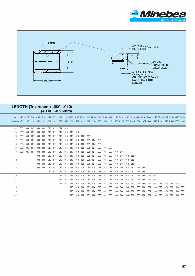
87
76.20
3.000
096
096
096
LENGTH (Tolerance + .000,-.010)(+0.00, -0.25mm)
mm 3.96 4.75 5.54 6.35 7.14 7.92 8.71 9.52 11.10 12.70 14.27 15.88 17.45 19.05 22.22 25.40 28.58 31.75 34.92 38.10 41.28 44.45 47.62 50.80 53.98 57.14 60.32 63.50 69.85
Bore Code .156 .187 .218 .250 .281 .312 .343 .375 .437 .500 .562 .625 .687 .750 .875 1.000 1.125 1.250 1.375 1.500 1.625 1.750 1.875 2.000 2.125 2.250 2.395 2.500 2.750
04 005 006 007 008 009 010 011 012 014
05 005 006 007 008 009 010 011 012 014 016 018
06 005 006 007 008 009 010 011 012 014 016 018 020 022
07 005 006 007 008 009 010 011 012 014 016 018 020 022 024 028
08 005 006 007 008 009 010 011 012 014 016 018 020 022 024 028
09 005 006 007 008 009 010 011 012 014 016 018 020 022 024 028 032 036
10 005 006 007 008 009 010 011 012 014 016 018 020 022 024 028 032 036 040 044
11 008 009 010 011 012 014 016 018 020 022 024 028 032 036 040 044 048 052
12 008 009 010 011 012 014 016 018 020 022 024 028 032 036 040 044 048 052
14 008 009 010 011 012 014 016 018 020 022 024 028 032 036 040 044 048 052
16 008 009 010 011 012 014 016 018 020 022 024 028 032 036 040 044 048 052 056 060
18 010 011 012 014 016 018 020 022 024 028 032 036 040 044 048 052 056 060
20 012 014 016 018 020 022 024 028 032 036 040 044 048 052 056 060 064 068
22 012 014 016 018 020 022 024 028 032 036 040 044 048 052 056 060 064 068
24 012 014 016 018 020 022 024 028 032 036 040 044 048 052 056 060 064 068 072 076 080 088
26 016 018 020 022 024 028 032 036 040 044 048 052 056 060 064 068 072 076 080 088
28 016 018 020 022 024 028 032 036 040 044 048 052 056 060 064 068 072 076 080 088
32 016 018 020 022 024 028 032 036 040 044 048 052 056 060 064 068 072 076 080 088
.020 (0.51mm)
.040 (1.02mm)CHAMFER
LENGTH
LINER
B D .015 (0.38mm)
.010 (0.25mm) MAXfor length CODE 012OR LESS .025 (0.64mm)MAX FOR ALL OTHERLENGTH
45° MAX CHAMFER OR BREAK EDGE
✕
15°±2°

88
AHJF-A, AHJF-CJournal, Flanged - Teflon LinedAS81934/2
Static limit load: Alum., 50000 psi ✕ B(L + F - .13) = lbs.Alum.,344N/mm2 ✕ B(L + F - 3.30) = N (N);CRES, 78500 psi ✕ B(L + F - .13) = lbs.CRES, 541 N/mm2 ✕ B(L + F - 3.30) = N (N)
Dynamic Capacity: 37500 ✕ B(L + F - .13) = lbs.Temperature: Operating temperature range -65° to 325°F.
(-54° to 163°)Concentricity tolerance between B and D diameters shall notexceed .003 (0.08mm) FIMBearings listed in table are approved for procurement to AS81934and M81934/2.
MATERIALSMaterials Code Journal Liner
AHJF-A Aluminum Alloy *Teflon/Fabric2024 T851 or Bonded to bore2024-T8511 per and flangeAMS-QQ-A-225/6 or face. No lub.AMS-QQ-A 200/3. Finish required.Anodized per MIL-A-8625,Type I or II or Alodinedper MIL-C-5541
AHJF-C CRES 17-4PH/AMS 5643 *Teflon/FabricH.T. to Condition Bonded to boreH-1150 and flangePassivated face. No lub.
required.
Shaft and Housing InformationFor optimum performance with lined journal bearings, consid-erable care must be exercised in the design of housings andshafts. For extreme applications involving dissimilar materials,elevated temperatures, or extreme loads, contact NMBEngineering for application recommendations. The adjacenttable applies to normal conditions.
* A trademark of E.I, duPont de Nemours & Co., Inc.
Shaft Housing
Diameter B -.0010 (0.025mm) D -.0006 (0.015mm)to -.0020 (0.051mm) to -.0011 (0.028mm)
Taper and Not to Not toRoundness exceed .0005 (0.013mm) exceed .0005 (0.013mm)
Finish 8 RHR MAX (0.2µmRa MAX)Polishedor honedafter grind
Hardness 50 HRC MIN
(B) (D) (H) (F) Sleeve Weight Flange WeightNMB Bore Diameter Outside Diameter Flange Diameter Flange Thickness Lbs./In. (Ref.) L = 1.000 (25.4mm) Lbs. (Ref.)Part Number ALUM. CRES ALUM. CRES ALUM. CRES
Inch mm Inch mm Inch mm Inch mm Inch mm lb/in g/mm
MIL-B-81934/2 +.0000 +0.000 +.0005 +0.013 +.0000 +0.000 +.000 +0.000 +.000 +0.000
Flanged -.0010 -0.025 -.0005 -0.013 -.0005 -0.013 -.020 -0.508 -.005 -0.127
AHJF04 .2515 6.388 .3760 9.550 .3760 9.550 .750 19.050 .0625 1.587 .006 0.11
AHJF05 .3140 7.976 .4386 11.140 .4386 11.140 .812 20.625 .0625 1.588 .007 0.12
AHJF06 .3765 9.563 .5012 12.730 .5012 12.730 .875 22.225 .0625 1.588 .008 0.14
AHJF07 .4390 11.151 .5638 14.321 .5638 14.321 .937 22.800 .0625 1.588 .009 0.16
AHJF08 .5015 12.738 .6265 15.913 .6265 15.913 1.000 25.400 .0625 1.588 .011 0.20
AHJF09 .5640 14.326 .6892 17.506 .6892 17.506 1.125 28.575 .0625 1.588 .012 0.21
AHJF10 .6265 15.913 .8142 20.681 .8142 20.681 1.250 31.750 .0625 1.588 .021 0.38
AHJF11 .6890 17.501 .8767 22.268 .8767 22.268 1.375 34.925 .0625 1.588 .022 0.39
AHJF12 .7515 19.088 .9393 23.858 .9393 23.858 1.500 38.100 .0625 1.588 .024 0.43
AHJF14 .8765 22.263 1.0645 27.038 1.0645 27.038 1.625 41.275 .0625 1.588 .028 0.50
AHJF16 1.0015 25.438 1.1898 30.221 1.1898 30.221 1.750 44.450 .0625 1.588 .031 0.55
AHJF18 1.1265 28.613 1.3148 33.396 1.3148 33.396 1.875 47.625 .0937 2.380 .035 0.62
AHJF20 1.2515 31.788 1.4398 36.571 1.4398 36.571 2.000 50.800 .0937 2.380 .038 0.68
AHJF22 1.3765 34.963 1.5648 39.746 1.3648 39.746 2.125 53.975 .0937 2.380 .041 0.73
AHJF24 1.5015 38.138 1.7523 44.508 1.7523 44.508 2.250 57.150 .0937 2.380 .062 1.11
AHJF26 1.6265 41.313 1.8773 47.638 1.8773 47.683 2.375 60.325 .0937 2.380 .067 1.20
AHJF28 1.7515 44.488 2.0023 50.858 2.0023 50.858 2.500 63.500 .0937 2.380 .071 1.27
AHJF32 2.0015 50.838 2.2523 57.208 2.2523 57.208 2.750 69.850 .0937 2.380 .081 1.45
lb/in g/mm lb/in g/mm lb/in g/mm
.016 0.29 .002 0.04 .006 0.11
.019 0.34 .003 0.05 .007 0.12
.022 0.39 .003 0.05 .007 0.12
.025 0.45 .003 0.05 .008 0.14
.028 0.50 .003 0.05 .009 0.16
.031 0.55 .004 0.07 .011 0.20
.056 1.00 .005 0.09 .014 0.25
.060 1.07 .006 0.11 .016 0.29
.065 1.16 .007 0.13 .020 0.36
.075 1.34 .008 0.14 .022 0.39
.084 1.50 .009 0.16 .024 0.43
.094 1.68 .015 0.27 .041 0.73
.103 1.84 .016 0.29 .045 0.80
.113 2.02 .017 0.30 .048 0.86
.171 3.05 .018 0.32 .051 0.91
.183 3.27 .020 0.36 .055 0.98
.196 3.50 .021 0.38 .058 1.04
.222 3.96 .023 0.41 .065 1.16
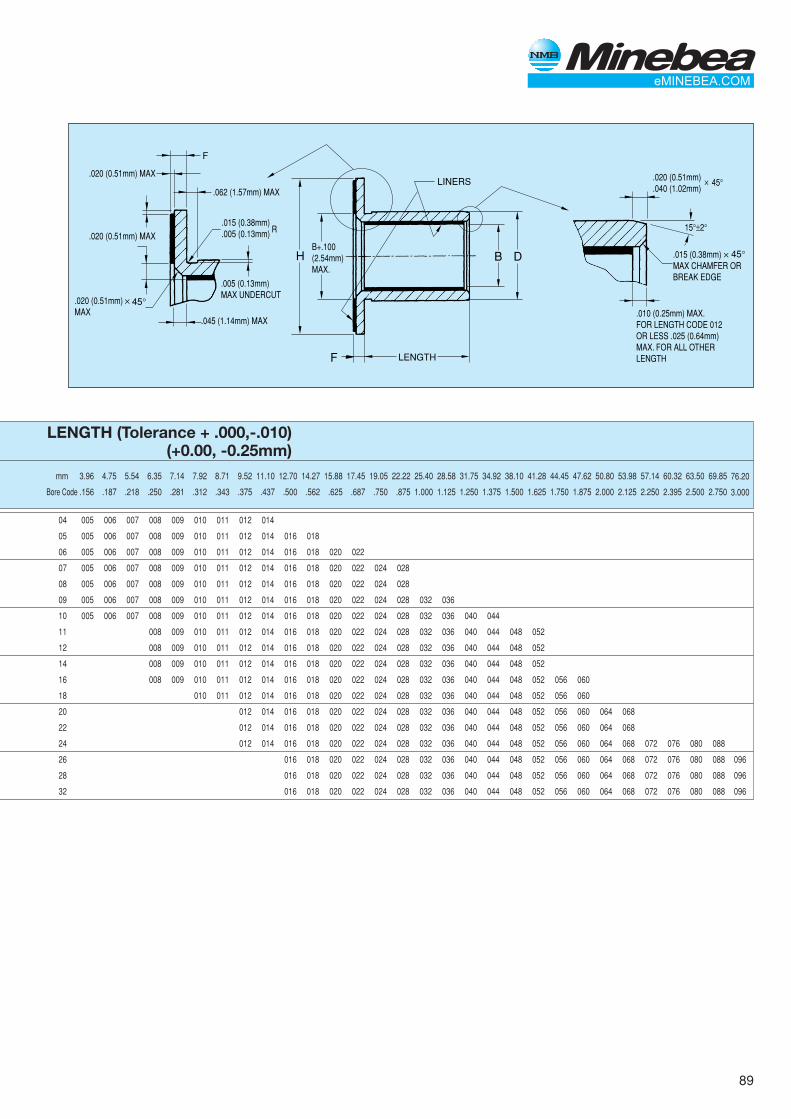
89
.015 (0.38mm)
.005 (0.13mm)
.062 (1.57mm) MAX
R
F
F
.020 (0.51mm)
.040 (1.02mm)
.020 (0.51mm) MAX
.020 (0.51mm) MAX
.020 (0.51mm)MAX
45°
45°
✕
✕
.005 (0.13mm)MAX UNDERCUT
LENGTH
LINERS
B D
.045 (1.14mm) MAX.010 (0.25mm) MAX.FOR LENGTH CODE 012OR LESS .025 (0.64mm)MAX. FOR ALL OTHER LENGTH
.015 (0.38mm)MAX CHAMFER OR BREAK EDGE
45°✕
15°±2°
HB+.100(2.54mm)MAX.
LENGTH (Tolerance + .000,-.010)(+0.00, -0.25mm)
mm 3.96 4.75 5.54 6.35 7.14 7.92 8.71 9.52 11.10 12.70 14.27 15.88 17.45 19.05 22.22 25.40 28.58 31.75 34.92 38.10 41.28 44.45 47.62 50.80 53.98 57.14 60.32 63.50 69.85
Bore Code .156 .187 .218 .250 .281 .312 .343 .375 .437 .500 .562 .625 .687 .750 .875 1.000 1.125 1.250 1.375 1.500 1.625 1.750 1.875 2.000 2.125 2.250 2.395 2.500 2.750
04 005 006 007 008 009 010 011 012 014
05 005 006 007 008 009 010 011 012 014 016 018
06 005 006 007 008 009 010 011 012 014 016 018 020 022
07 005 006 007 008 009 010 011 012 014 016 018 020 022 024 028
08 005 006 007 008 009 010 011 012 014 016 018 020 022 024 028
09 005 006 007 008 009 010 011 012 014 016 018 020 022 024 028 032 036
10 005 006 007 008 009 010 011 012 014 016 018 020 022 024 028 032 036 040 044
11 008 009 010 011 012 014 016 018 020 022 024 028 032 036 040 044 048 052
12 008 009 010 011 012 014 016 018 020 022 024 028 032 036 040 044 048 052
14 008 009 010 011 012 014 016 018 020 022 024 028 032 036 040 044 048 052
16 008 009 010 011 012 014 016 018 020 022 024 028 032 036 040 044 048 052 056 060
18 010 011 012 014 016 018 020 022 024 028 032 036 040 044 048 052 056 060
20 012 014 016 018 020 022 024 028 032 036 040 044 048 052 056 060 064 068
22 012 014 016 018 020 022 024 028 032 036 040 044 048 052 056 060 064 068
24 012 014 016 018 020 022 024 028 032 036 040 044 048 052 056 060 064 068 072 076 080 088
26 016 018 020 022 024 028 032 036 040 044 048 052 056 060 064 068 072 076 080 088
28 016 018 020 022 024 028 032 036 040 044 048 052 056 060 064 068 072 076 080 088
32 016 018 020 022 024 028 032 036 040 044 048 052 056 060 064 068 072 076 080 088
76.20
3.000
096
096
096
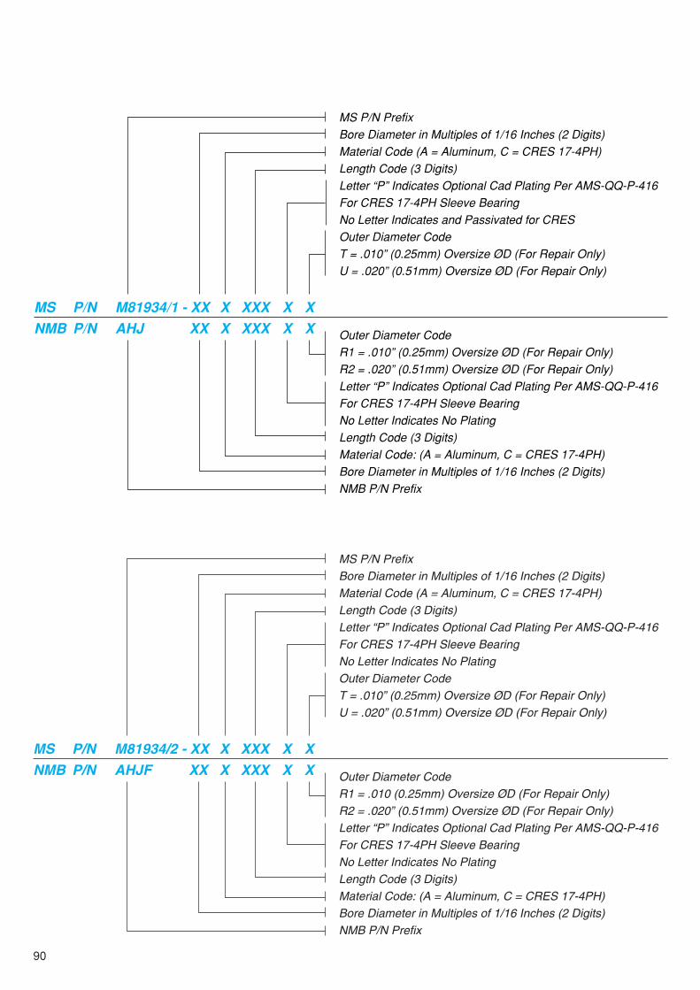
90
MS P/N PrefixBore Diameter in Multiples of 1/16 Inches (2 Digits)Material Code (A = Aluminum, C = CRES 17-4PH)Length Code (3 Digits)Letter “P” Indicates Optional Cad Plating Per AMS-QQ-P-416For CRES 17-4PH Sleeve BearingNo Letter Indicates and Passivated for CRESOuter Diameter CodeT = .010” (0.25mm) Oversize ØD (For Repair Only)U = .020” (0.51mm) Oversize ØD (For Repair Only)
Outer Diameter CodeR1 = .010” (0.25mm) Oversize ØD (For Repair Only)R2 = .020” (0.51mm) Oversize ØD (For Repair Only)Letter “P” Indicates Optional Cad Plating Per AMS-QQ-P-416For CRES 17-4PH Sleeve BearingNo Letter Indicates No PlatingLength Code (3 Digits)Material Code: (A = Aluminum, C = CRES 17-4PH)Bore Diameter in Multiples of 1/16 Inches (2 Digits)NMB P/N Prefix
MS P/N M81934/1 - XX X XXX X XNMB P/N AHJ XX X XXX X X
MS P/N Prefix
Bore Diameter in Multiples of 1/16 Inches (2 Digits)
Material Code (A = Aluminum, C = CRES 17-4PH)
Length Code (3 Digits)
Letter “P” Indicates Optional Cad Plating Per AMS-QQ-P-416
For CRES 17-4PH Sleeve Bearing
No Letter Indicates No Plating
Outer Diameter Code
T = .010” (0.25mm) Oversize ØD (For Repair Only)
U = .020” (0.51mm) Oversize ØD (For Repair Only)
Outer Diameter Code
R1 = .010 (0.25mm) Oversize ØD (For Repair Only)
R2 = .020” (0.51mm) Oversize ØD (For Repair Only)
Letter “P” Indicates Optional Cad Plating Per AMS-QQ-P-416
For CRES 17-4PH Sleeve Bearing
No Letter Indicates No Plating
Length Code (3 Digits)
Material Code: (A = Aluminum, C = CRES 17-4PH)
Bore Diameter in Multiples of 1/16 Inches (2 Digits)
NMB P/N Prefix
MS P/N M81934/2 - XX X XXX X X
NMB P/N AHJF XX X XXX X X

91
OVERSIZE BEARING DIMENSIONS (OUTSIDE DIMENSION)
M81934/1. M81934/2
DASH Nominal 1st 2ndNo Bore Size Oversize Oversize
(.010) ØD (.020) ØD
-04 .2500 (6.350mm) .3860 (9.804mm) .3960 (10.058mm)
-05 .3125 (7.938mm) .4486 (11.394mm) .4586 (11.648mm)
-06 .3750 (9.525mm) .5112 (12.984mm) .5212 (13.238mm)
-07 .4375 (11.112mm) .5738 (14.575mm) .5838 (14.829mm)
-08 .5000 (12.700mm) .6365 (16.167mm) .6465 (16.421mm)
-09 .5625 (14.288mm) .6992 (17.760mm) .7092 (18.014mm)
-10 .6250 (15.875mm) .8242 (20.935mm) .8342 (21.189mm)
-11 .6875 (17.462mm) .8867 (22.522mm) .8967 (22.776mm)
-12 .7500 (19.050mm) .9493 (24.112mm) .9593 (24.366mm)
-14 .8750 (22.225mm) 1.0745 (27.292mm) 1.0845 (27.546mm)
-16 1.0000 (25.400mm) 1.1998 (30.475mm) 1.2098 (30.729mm)
-18 1.1250 (28.575mm) 1.3248 (33.650mm) 1.3348 (33.904mm)
-20 1.2500 (31.750mm) 1.4498 (36.825mm) 1.4598 (37.079mm)
-22 1.3750 (34.925mm) 1.5748 (40.000mm) 1.5848 (40.254mm)
-24 1.5000 (38.100mm) 1.7623 (44.762mm) 1.7723 (45.016mm)
-26 1.6250 (41.275mm) 1.8873 (47.937mm) 1.8973 (48.191mm)
-28 1.7500 (44.450mm) 2.0123 (51.112mm) 2.0223 (51.366mm)
-32 2.0000 (50.800mm) 2.2623 (57.462mm) 2.2723 (57.716mm)
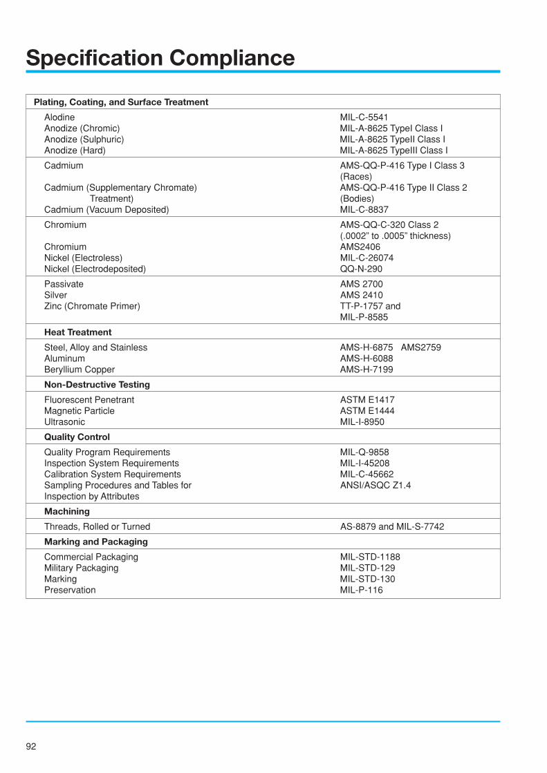
92
Specification Compliance
Plating, Coating, and Surface Treatment
Alodine MIL-C-5541Anodize (Chromic) MIL-A-8625 TypeI Class IAnodize (Sulphuric) MIL-A-8625 TypeII Class IAnodize (Hard) MIL-A-8625 TypeIII Class I
Cadmium AMS-QQ-P-416 Type I Class 3(Races)
Cadmium (Supplementary Chromate) AMS-QQ-P-416 Type II Class 2Treatment) (Bodies)
Cadmium (Vacuum Deposited) MIL-C-8837
Chromium AMS-QQ-C-320 Class 2(.0002” to .0005” thickness)
Chromium AMS2406Nickel (Electroless) MIL-C-26074Nickel (Electrodeposited) QQ-N-290
Passivate AMS 2700Silver AMS 2410Zinc (Chromate Primer) TT-P-1757 and
MIL-P-8585
Heat Treatment
Steel, Alloy and Stainless AMS-H-6875 AMS2759Aluminum AMS-H-6088Beryllium Copper AMS-H-7199
Non-Destructive Testing
Fluorescent Penetrant ASTM E1417Magnetic Particle ASTM E1444Ultrasonic MIL-I-8950
Quality Control
Quality Program Requirements MIL-Q-9858Inspection System Requirements MIL-I-45208Calibration System Requirements MIL-C-45662Sampling Procedures and Tables for ANSI/ASQC Z1.4Inspection by Attributes
Machining
Threads, Rolled or Turned AS-8879 and MIL-S-7742
Marking and Packaging
Commercial Packaging MIL-STD-1188Military Packaging MIL-STD-129Marking MIL-STD-130Preservation MIL-P-116

93
INCH/METRIC CONVERSION FACTORSINCH
FRACT. DECIMAL mm
.00004 0.001
.0004 0.010
.0010 0.025
.0020 0.051
.0030 0.076
.0039 0.100
.0050 0.127
.0098 0.250
.0100 0.2541/64 .0156 0.3961/32 .0312 0.793
.0394 1.0003/64 .0469 1.191
.0591 1.5001/16 .0625 1.5885/64 .0781 1.984
.0787 2.0003/32 .0937 2.380
.0984 2.500
.1000 2.5407/64 .1094 2.779
.1181 3.0001/8 .1250 3.175
.1378 3.5009/64 .1406 3.5715/32 .1562 3.967
.1575 4.00011/64 .1719 4.366
.1772 4.5003/16 .1875 4.762
.1969 5.00013/64 .2031 5.1597/32 .2188 5.558
15/64 .2344 5.954
.2362 6.0001/4 .2500 6.350
INCHFRACT. DECIMAL mm
17/64 .2656 6.747.2756 7.000
9/32 .2812 7.14219/64 .2969 7.5415/16 .3125 7.938
.3150 8.00021/64 .3281 8.33411/32 .3438 8.733
.3543 9.00023/64 .3594 9.129
3/8 .3750 9.52525/64 .3906 9.921
.3937 10.00013/32 .4062 10.31727/64 .4219 10.716
.4331 11.0007/16 .4375 11.112
29/64 .4531 11.50915/32 .4687 11.905
.4724 12.00031/64 .4844 12.304
1/2 .5000 12.700
.5118 13.00033/64 .5156 13.09617/32 .5312 13.49235/64 .5469 13.891
.5512 14.0009/16 .5625 14.288
37/64 .5781 14.684
.5906 15.00019/32 .5937 15.08039/64 .6094 15.479
5/8 .6250 15.875
.6299 16.00041/64 .6406 16.27121/32 .6562 16.667
INCHFRACT. DECIMAL mm
.6693 17.00043/64 .6719 17.06611/16 .6875 17.46245/64 .7031 17.859
.7086 18.00023/32 .7187 18.25547/64 .7344 18.654
.7480 19.0003/4 .7500 19.050
49/64 .7656 19.44525/32 .7812 19.842
.7874 20.00051/64 .7969 20.24113/16 .8125 20.638
.8268 21.00053/64 .8281 21.03427/32 .8437 21.43055/64 .8594 21.829
.8661 22.0007/8 .8750 22.225
57/64 .8906 22.621
.9055 23.00029/32 .9062 23.01759/64 .9219 23.41615/16 .9375 23.812
.9449 24.00061/64 .9531 24.20931/32 .9687 24.605
.9843 25.00063/64 .9844 25.004
1 1.0000 25.400
1.0630 27.000
1.1024 28.000
1.1811 30.000
11/4 1.2500 31.7501.2992 33.000
INCHFRACT. DECIMAL mm
1.3780 35.0001.4173 36.000
11/2 1.5000 38.100
1.5354 39.000
1.5748 40.000
1.6535 42.00013/4 1.7500 44.450
1.7717 45.000
1.8898 48.000
1.9685 50.000
2 2.000 50.8002.0472 52.000
2.1654 55.0002.2047 56.000
21/4 2.2500 57.150
2.3622 60.000
21/2 2.5000 63.500
2.5197 64.00023/4 2.7500 69.850
2.8346 72.000
2.9528 75.000
3 3.0000 76.200
3.1496 80.00031/4 3.2500 82.550
31/2 3.5000 88.9003.5433 90.000
33/4 3.7500 95.250
3.9370 100.000
4 4.0000 101.600
41/4 4.2500 107.9504.3307 110.000
41/2 4.5000 114.300
4.7244 120.000
43/4 4.7500 120.650
5. 5.0000 127.00051/2 5.5000 139.700
INCH/METRIC CONVERSION FACTORSinches ✕ 25.4 = Millimeters
Millimeters ✕ 0.03937 = Inches
Sq. Inches ✕ 6.4515 = Sq. Centimeters
Sq. Centimeters ✕ 0.155 = Sq. inches
Pounds ✕ 0.4536 = Kilograms
Kilograms ✕ 2.2046 = Pounds
Lbs. Per In.2 ✕ 0.689 = N per cm2
N per cm2 ✕ 1.45 = Lbs. Per In.2
Pounds (Force) ✕ 4.448 = Newtons
Newtons ✕ 0.2248 = Pounds (Force)
Temperatuer Conversion (Approximate)
Degrees C = (Degrees F-32) (.5556)
Degress F = (Degrees C) (1.8) +32
Inch/Metric conversion on this catalog is in accordance with JIS Z 8401.
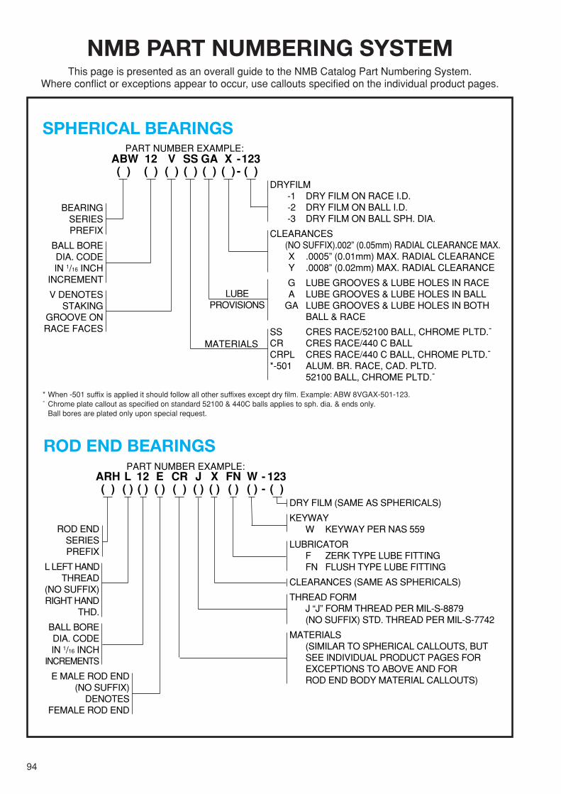
94
NMB PART NUMBERING SYSTEMThis page is presented as an overall guide to the NMB Catalog Part Numbering System.
Where conflict or exceptions appear to occur, use callouts specified on the individual product pages.
SPHERICAL BEARINGS
* When -501 suffix is applied it should follow all other suffixes except dry film. Example: ABW 8VGAX-501-123.- Chrome plate callout as specified on standard 52100 & 440C balls applies to sph. dia. & ends only.
Ball bores are plated only upon special request.
PART NUMBER EXAMPLE:ABW 12 V SS GA X -123( ) ( ) ( ) ( ) ( ) ( ) - ( )
BEARINGSERIESPREFIX
BALL BOREDIA. CODEIN 1/16 INCH
INCREMENT
V DENOTESSTAKING
GROOVE ONRACE FACES
LUBEPROVISIONS
DRYFILM-1 DRY FILM ON RACE I.D.-2 DRY FILM ON BALL I.D.-3 DRY FILM ON BALL SPH. DIA.
CLEARANCES (NO SUFFIX).002” (0.05mm) RADIAL CLEARANCE MAX.
X .0005” (0.01mm) MAX. RADIAL CLEARANCEY .0008” (0.02mm) MAX. RADIAL CLEARANCE
G LUBE GROOVES & LUBE HOLES IN RACEA LUBE GROOVES & LUBE HOLES IN BALL
GA LUBE GROOVES & LUBE HOLES IN BOTHBALL & RACE
SS CRES RACE/52100 BALL, CHROME PLTD.-
CR CRES RACE/440 C BALLCRPL CRES RACE/440 C BALL, CHROME PLTD.-
*-501 ALUM. BR. RACE, CAD. PLTD.52100 BALL, CHROME PLTD.-
MATERIALS
ROD END BEARINGSPART NUMBER EXAMPLE:
DRY FILM (SAME AS SPHERICALS)
KEYWAYW KEYWAY PER NAS 559
LUBRICATORF ZERK TYPE LUBE FITTINGFN FLUSH TYPE LUBE FITTING
CLEARANCES (SAME AS SPHERICALS)
THREAD FORMJ “J” FORM THREAD PER MIL-S-8879(NO SUFFIX) STD. THREAD PER MIL-S-7742
MATERIALS(SIMILAR TO SPHERICAL CALLOUTS, BUTSEE INDIVIDUAL PRODUCT PAGES FOREXCEPTIONS TO ABOVE AND FORROD END BODY MATERIAL CALLOUTS)
ARH L 12 E CR J X FN W - 123( ) ( ) ( ) ( ) ( ) ( ) ( ) ( ) ( ) - ( )
ROD ENDSERIESPREFIX
L LEFT HAND THREAD
(NO SUFFIX)RIGHT HAND
THD.
BALL BOREDIA. CODEIN 1/16 INCH
INCREMENTS
E MALE ROD END(NO SUFFIX)
DENOTESFEMALE ROD END