beamforming and mimo digital radio baseband and … the mimo system by performing matrix operations...
TRANSCRIPT

Beamforming and MIMO Digital Radio Baseband and
Testbed for Next Generation Wireless Systems
Niral Sheth
Electrical Engineering and Computer SciencesUniversity of California at Berkeley
Technical Report No. UCB/EECS-2016-95
http://www.eecs.berkeley.edu/Pubs/TechRpts/2016/EECS-2016-95.html
May 13, 2016

Copyright © 2016, by the author(s).All rights reserved.
Permission to make digital or hard copies of all or part of this work forpersonal or classroom use is granted without fee provided that copies arenot made or distributed for profit or commercial advantage and that copiesbear this notice and the full citation on the first page. To copy otherwise, torepublish, to post on servers or to redistribute to lists, requires prior specificpermission.
Acknowledgement
Special thanks to Borivoje Nikolic, Elad Alon, and Vladmir Stojanovic fortheir guidance. I'd also like to thank the graduate students at BWRC fortheir help and support throughout the project: Angie Wang, Paul Rigge,Antonio Puglielli, and Christopher Yarp.
Table of Contents
Chapter One: Technical Contributions (Individually Written) .................................................................... 2
Introduction .............................................................................................................................................. 2
Background ............................................................................................................................................... 4
Software-Defined Radio ........................................................................................................................ 5
CHISEL ................................................................................................................................................... 6
OFDM Modulation Scheme .................................................................................................................. 8
Smart Antennas .................................................................................................................................... 9
Design ...................................................................................................................................................... 10
Matrix Multiplication Unit .................................................................................................................. 11
Controller Infrastructure ..................................................................................................................... 13
Validation ................................................................................................................................................ 15
Methodology and Tools ...................................................................................................................... 15
Results ................................................................................................................................................. 16
Conclusions ............................................................................................................................................. 17
References .............................................................................................................................................. 18
Chapter Two: Engineering Leadership Paper (Team Written) .................................................................. 19
Introduction ............................................................................................................................................ 19
Trends and Intellectual Property Strategy .............................................................................................. 19
Industry Analysis ..................................................................................................................................... 21
Market Strategy ...................................................................................................................................... 24
References .............................................................................................................................................. 25

2
Introduction
With the recent surge in wireless communications, the radio industry has seen an
increase in the number of different communication standards, each requiring its own specific
hardware and processing. Our project is part of a larger effort to address the need for radio
interoperability with these various standards through the development of hardware generators
for a software defined radio (SDR) system. These hardware generators will be created using
Chisel, a hardware construction language. When given a set of parameters or constraints, the
hardware generators will automatically output circuit designs for the given application, thereby
accelerating the hardware design process and introducing a new method for multi-standard
support. Specifically, our team was tasked with the development of generators for the system’s
smart antenna (i.e. beamforming and MIMO) blocks.
For this project, our team accomplished the design of two hardware generators: the
CORDIC and the MIMO Receiver blocks. The CORDIC block is simply a set of hardware efficient
algorithms capable of performing hyperbolic and trigonometric calculations without the use of
a hardware multiplier. By avoiding use of hardware multipliers, the CORDIC architecture
reduces the number of logic gates required to perform these trigonometric calculations,
thereby saving significant circuit power and area in exchange for less accuracy. The MIMO block
consists of smart antenna techniques useful for multiple antenna radio systems. These
techniques, in essence, provide improved spectral efficiency (i.e. better signal and data speeds)
and have become a necessity for almost any modern radio system.

3
The work breakdown for the design tasks involved are depicted in the diagram below
(see Figure 1). For the CORDIC block, tasks consisted of three primary components: enabling
hardware generation for variable data lengths, adding compatibility for fixed and double data
types and thoroughly validating the block’s functionality. The CORDIC block has a wide range of
applications. While originally designed for incorporation with the carrier frequency offset
correction (CFO) block1, it can be used to perform multiplications in the MIMO block as well. To
learn more about the CORDIC design, please refer to Eva Xu’s paper. For the MIMO block, tasks
consisted of two hardware generation sub-blocks: the beamforming matrix sub-block and the
matrix multiplication sub-block. The former involves determination of beamforming coefficients
for the MIMO system by performing matrix operations on channel estimates between transmit-
receive antenna pairs in hardware. By allowing isolation of unique data streams, these
coefficients effectively enable the MIMO system’s ability to simultaneously transmit multiple
data streams. To learn more about the design of this sub-block, please refer to Sam Yuan’s
paper.
The matrix multiplication sub-block performs the processes required to convert received
data into unique data streams. Furthermore, this sub-block also functions as the shell for the
MIMO system in that it serves as the controller for operating the two different sub-blocks. This
paper focuses on these topics and is organized as follows. The paper first presents a detailed
background on the design tools used and the relevant radio modem and schemes used. The
paper then moves on to discuss the hardware design and validation steps involved in creating
1 The CFO block is a baseband component of the radio processing chain and is outside the scope of this project.

4
the matrix multiplication sub-block as well as their significance. Finally, concluding remarks
regarding current progress and future steps are offered.
Background
To better understand the significance of hardware generation, the software-defined radio
concept and the Chisel hardware language are first discussed. These topics highlight the
challenges currently faced in traditional hardware design flows and the advantages these tools
offer. Given that the project aims to use these tools in the context of radio communications, an
overview of the relevant radio technologies involved in the project are provided. Specifically,
the overall project aims to use the SDR design paradigm to construct a generic orthogonal
frequency division multiplexing (OFDM) modem. The OFDM scheme offers advantages such as
improved spectral efficiency and will be discussed in terms of its relevance to our generator
Figure 1. Work breakdown structure for first project status reporting
deliverables.

5
designs. Since our team project focuses on smart antennas (a component of the ODFM
modem), these algorithms are discussed as well.
A. Software-defined Radio (SDR)
In traditional radio, processing occurs through application specific hardware (e.g. ASICs).
While this type of hardware is efficient, its compatibility is typically limited to a single
communication interface or standard. To overcome this limitation, SDR emerged as a new radio
solution in the mid 1980’s (Brannon, n.d.:3). Instead of application specific hardware, SDR
typically utilizes reprogrammable logic arrays such as field programmable gate arrays (FPGAs).
These chips allow developers to modify the radio device through software re-definable logic
rather than changing the hardware effectively enabling the implementation of rapid design
methodologies. However, these FPGA chips were significantly less efficient and more expensive
to implement than their ASIC counterparts. These drawbacks limited their applicability in
consumer products at that time (Brannon, n.d.:3-4).
With recent advances in technology, the implementation of SDR for commercial
applications is becoming increasingly practicable. Over the past decade, the semiconductor
industry has seen a large boom in response to the high demand for low cost equipment from
the communication and other device manufacturing industries. According to IBIS, the price of
semiconductors has steadily declined due to advances in technology and production efficiency
and is projected to decline at an annual rate of 2.2 % (Ulama 2015:6-9). Furthermore, these
advancements in low cost semiconductor equipment are concurrent with the release of low
cost, high performance digital signal processors (DSPs) and FPGAs. These trends have increased

6
the feasibility of SDR for use in commercial applications and have contributed to its recent
reemergence (Brannon, n.d.:4). The viability of SDR brings with it the ability to transform
hardware design into an Agile process, thereby making the design flexible to rapid changes in
project requirements.
Given the increasing viability of SDR, many platforms are available in the literature that
enable reconfigurable radio design. Radio design tools exist for SDR simulation and synthesis on
National Instruments RIO and for software simulation on Simulink. While these tools indeed
enable rapid design prototyping compared to traditional approaches, they are still quite limited
in that they provide little to no design automation or reuse. Current tools lack component
libraries, forcing them to rely on engineers to either develop designs from scratch or outsource
them from some third party, a costly alternative in terms of required time and skill. An
approach that could generate an initial design architecture and be continually modified to
satisfy design constraints would greatly accelerate existing design flows (DiPierro 2008:1). Our
SDR platform aims to achieve such a goal by taking advantage of the CHISEL language to create
a library of hardware generators for the entire radio processing chain.
B. CHISEL
To design the hardware generators, the CHISEL hardware description language was
used. Traditional hardware design mostly relies on the use of Verilog or VHDL as the hardware
description language. These languages have dominated since their inception around the mid
1980’s and have seen little evolution since then. Aside from problems involving usage and
construct synthesizability, these languages lack strong notions of abstraction and module

7
reusability that lead to poor design space exploration and in some cases, inefficient hardware
implementations. To address these challenges, the CHISEL language was developed with the
platform-based paradigm in mind. To be more precise, CHISEL enables the design of powerful
hardware generators by introducing modern software features such as functional programming
to specify the design of low level blocks. The language is also capable of performing design
simulation in C++ and code generation into Verilog for standard FPGA emulation or ASIC
synthesis. By raising the level of abstraction in hardware design, CHISEL also allows for
significant design reuse thereby enabling the development of platform-based technologies
(Bachrach 2012).
In this project, the Chisel language was adapted in such a manner. Using the CHISEL
language, the Chisel Digital Signal Processing (DSP) Environment2 was created as a platform for
the construction of DSP hardware generators such as our project’s digital radio chain. In
addition to the base benefits of the CHISEL language, the CHISEL DSP environment provides the
necessary resources to specifically create and test radio circuit designs because it introduces
data types and constructs not present to the standard Chisel library. For instance, Chisel does
not easily allow the use of double or fixed point data types which are important for accurate
signal processing and instead uses integer approximations which can result in high error rates.
Furthermore, the environment enhances the language’s interaction with the programmer by
improving debugging output and data pipelining features thereby making it a suitable tool for
our project.
2 https://github.com/ucb-art/ChiselDSP - GitHub repository for the Chisel DSP environment

8
C. Radio Scheme: Orthogonal Frequency Division Multiplexing (OFDM)
OFDM currently serves as the most popular scheme for broadband wireless
communication seeing use in high speed applications such as Wi-Fi and LTE. Given the
increasing importance of this scheme in the development of next generation wireless systems,
the hardware generators designed in this project will constitute a generic OFDM modem. The
widespread use of OFDM primarily arises from the technique’s high spectral efficiency and
robustness under poor channel conditions.
Traditional systems utilize non-overlapping carrier waves at a single frequency to
transmit unique data streams. While this allows multiplexing of unique signals, these methods
achieve poor spectral efficiency as they require allocation of large bandwidths for each
separate signal. Moreover, these methods are highly susceptible to frequency-dependent
channel and interference effects thereby requiring the need for complex equalization filters at
the receiver.
On the other hand, OFDM follows a multi-carrier scheme that uses a specified number
of overlapping sub-carriers within a given bandwidth (see Figure 2) to represent the signal.
These sub-carriers are each assigned only a portion of the total bandwidth and consequently
have a much slower bit rate than larger bandwidth carriers. However, the key to OFDM is the
orthogonality between the sub-carriers that allows them to be overlapped such that maximum
power of each sub-carrier aligns with the minimum power of adjacent channels. This effectively
allows for increased data rates for a given bandwidth (i.e. higher spectral efficiency) compared
to single carrier systems. Furthermore, the use of multiple sub-carriers gives the signal more
robustness towards frequency selective channel effects (Marchetti, et al. 2009).

9
In the context of our project, the smart antenna generators must be integrated with the
OFDM scheme. To do so simply amounts to performing the relevant MIMO digital signal
processing for each OFDM sub-carrier. The resultant air interface termed MIMO-ODM allows
for high capacity and data speeds as well as reduced receiver complexity relative to other air
interfaces and currently dominates in the application domain for high-speed, broadband
communication.
D. Smart Antenna Techniques
As mentioned earlier, improvements in channel capacity and data speeds have become
increasingly important. Due to the exponential growth in the number of radio devices in today’s
market as well as the demand for higher data rates, wireless service providers are facing
challenges in providing the necessary bandwidth to keep up with these trends. According to
IBIS, mobile internet access primarily drives the expansion of the wireless telecommunication
industry with an estimated annual growth rate of 24.6 %, in terms of new mobile connections
over the past five years (Blau 2015:5-7). This annual expansion simultaneously drives up the
Figure 2. Simple illustration of single vs. multi-carrier schemes

10
cost to maintain radio capacity as the radio spectrum becomes increasingly scarce (Blau
2015:7). With a limited set of radio frequencies, spectral efficiency becomes increasingly
important to support consumer demand for bandwidth.
The rise in wireless traffic coupled with limitations of the spectrum have sparked
interest in smart antenna techniques which can address these bandwidth concerns. Smart
antenna beamforming directionally transmits information which allows for frequency reuse in a
given area. By reusing frequencies, more information can be sent over the same band of
frequencies thereby increasing spectral efficiency. Similarly, receiver MIMO and beamforming
allow further frequency reuse by using spatial diversity techniques to isolate unique data
streams from simultaneously transmitted data streams of a given frequency. As smart antennas
continue to evolve over different generations, device interoperability once again becomes a
point of concern. Since different protocols or applications will undoubtedly implement smart
antennas differently, motivation exists for the design of flexible smart antenna hardware
generators.
Design
As previously mentioned, technical contributions focus on the design of the MIMO DSP
controller and matrix multiplication sub-unit. This section starts by discussing the role and
current hardware design for the matrix multiplication unit as well as expected additions to be
completed soon. It then presents a high level overview and significance of the controller as well
as the expected implementation.

11
A. Matrix Multiplication
To understand the role of this sub-block, a brief overview of the fundamentals behind a
simple MIMO receiver are presented. In a MIMO system such as the one modeled in Figure 3,
the system consists of a set of transmit and receive antennas. Here, the set of transmit
antennas are assumed to each transmit unique data signals uniformly in space3. As these signals
travel through the channel and collect at each of the receiver antennas, they typically
encounter different (i.e. uncorrelated) channel effects. If sufficient environmental diversity is
present, these channel effects can serve as spatial signatures of the original signals at the
receiver. In other words, the channel effects allow the receiver signal to be represented as a
linear combination of each of the original transmit signals, thereby giving rise to the following
matrix-vector equation (also shown in Figure 3):
𝑦 = 𝐻𝑠 + 𝑛
In this equation, y represents the vector of receive signals, H represents a matrix of
channel gains between each combination of transmit-receive antennas, and n represents
Gaussian noise. In order to recover the original signal, the effects of the channel need to be
equalized using the H matrix (the channel estimation block shown is being developed by
another team). Since the channel matrix represents spatial effects on the signal, the matrix
used to perform the inverse operation (i.e. spatial reconstruction) is termed the beamforming
matrix (represented by G below) and follows the equation:
𝑠 = 𝐺𝑦
3 While transmit beamforming is also possible, this is typically used in the design of MIMO systems such as multi-user or massive MIMO (which are outside the scope of this task).

12
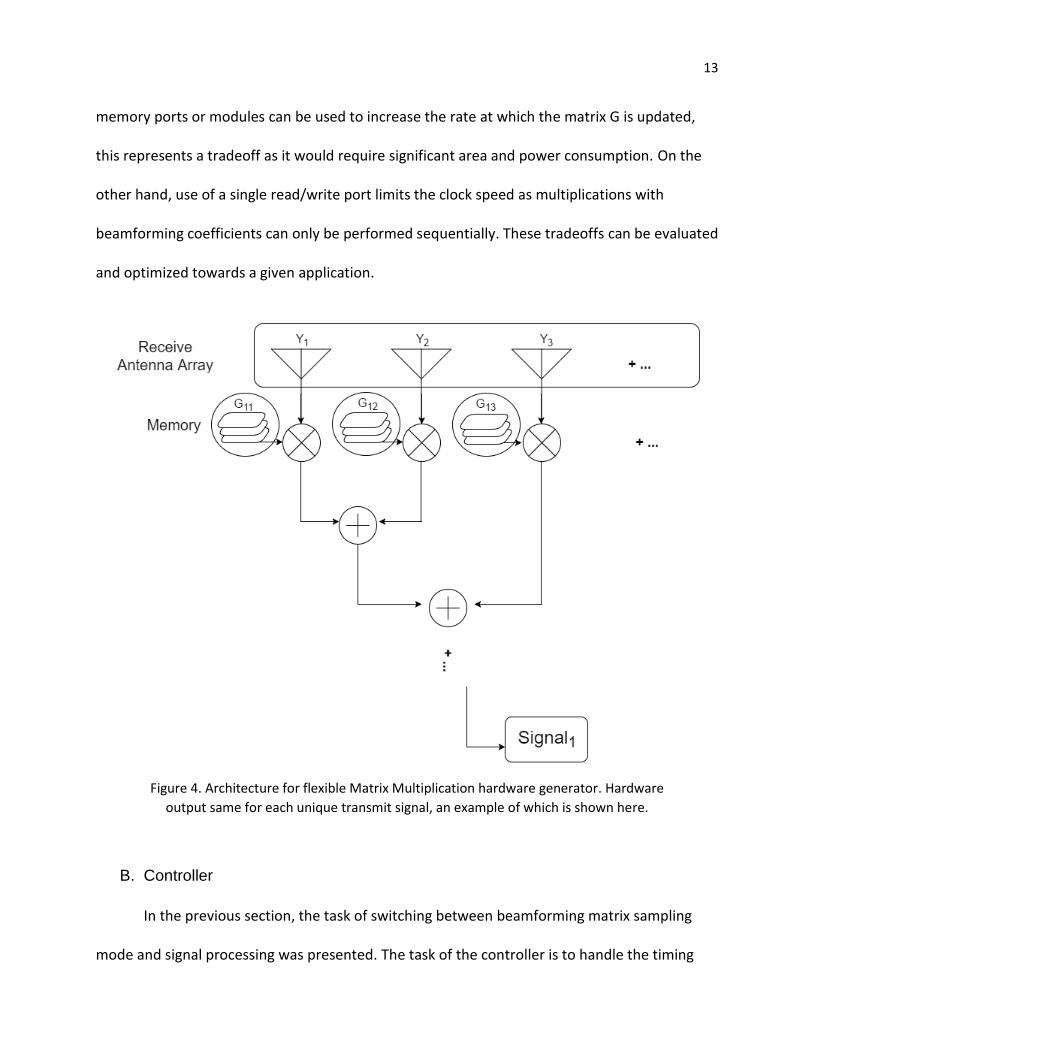
Using this framework, a matrix multiplier hardware generator was implemented in the
CHISEL DSP Environment with support for double and fixed data types. The basic operation of
this block relies on generating the appropriate multiplier and adder tree to perform the matrix
operation for a variable number of transmit and receive antennas. The current architecture for
this design is represented in Figure 4. In order to perform the processing, the block also
requires the beamforming matrix G. Since the environment between the transmitter and
receiver is subject to change, the channel estimation and beamforming matrices need to be
continually updated. However, since the determination of G and the channel estimation
process take multiple cycles, it is unrealistic to perform processing with new G values each
cycle. Instead, the matrix G is sampled at set intervals and stored in registers.
An alternative approach to realizing this memory is the implementation of SRAM
memory. Currently, Chisel DSP supports memory with a single read/write port. While more
Figure 3. Simple MIMO Receiver model
13
memory ports or modules can be used to increase the rate at which the matrix G is updated,
this represents a tradeoff as it would require significant area and power consumption. On the
other hand, use of a single read/write port limits the clock speed as multiplications with
beamforming coefficients can only be performed sequentially. These tradeoffs can be evaluated
and optimized towards a given application.
B. Controller
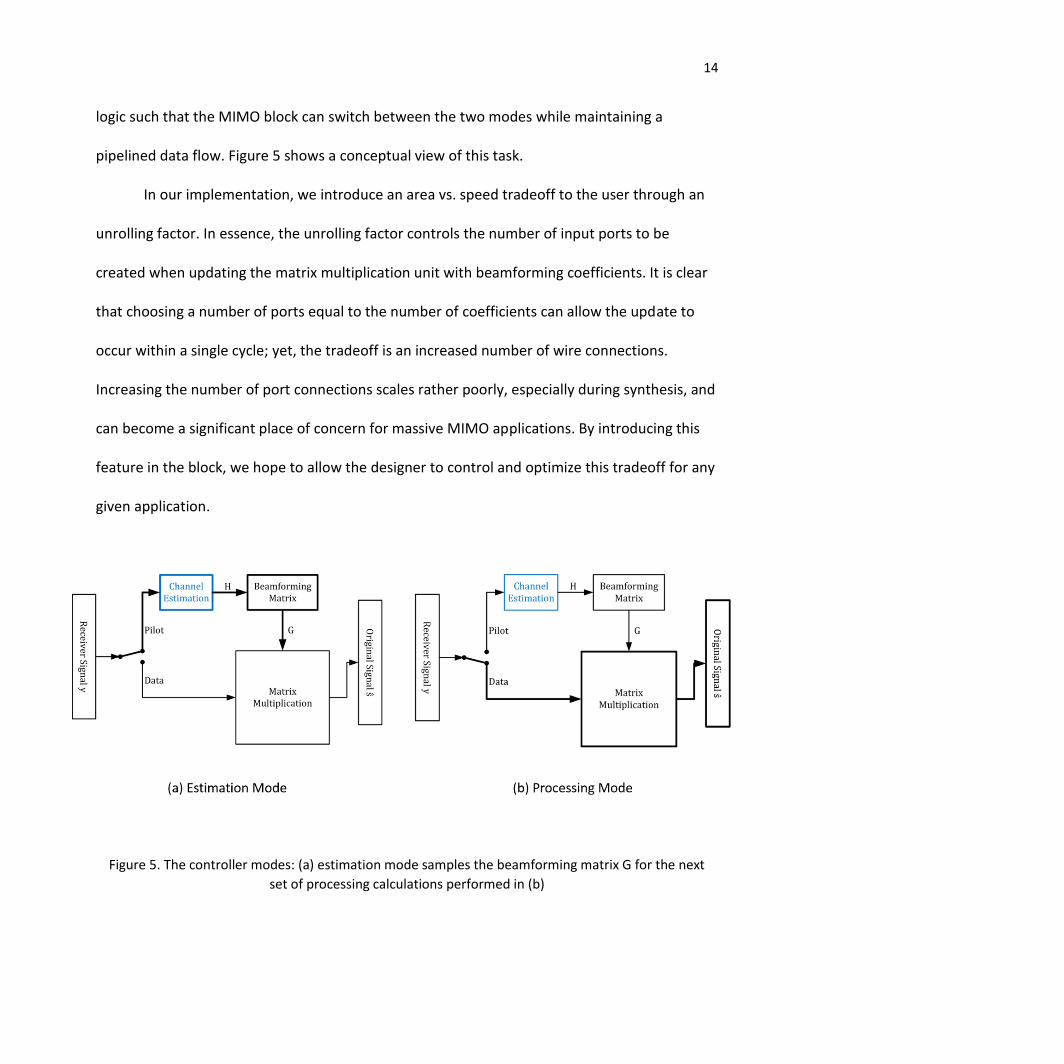
In the previous section, the task of switching between beamforming matrix sampling
mode and signal processing was presented. The task of the controller is to handle the timing
Figure 4. Architecture for flexible Matrix Multiplication hardware generator. Hardware
output same for each unique transmit signal, an example of which is shown here.
14
logic such that the MIMO block can switch between the two modes while maintaining a
pipelined data flow. Figure 5 shows a conceptual view of this task.
In our implementation, we introduce an area vs. speed tradeoff to the user through an
unrolling factor. In essence, the unrolling factor controls the number of input ports to be
created when updating the matrix multiplication unit with beamforming coefficients. It is clear
that choosing a number of ports equal to the number of coefficients can allow the update to
occur within a single cycle; yet, the tradeoff is an increased number of wire connections.
Increasing the number of port connections scales rather poorly, especially during synthesis, and
can become a significant place of concern for massive MIMO applications. By introducing this
feature in the block, we hope to allow the designer to control and optimize this tradeoff for any
given application.
Figure 5. The controller modes: (a) estimation mode samples the beamforming matrix G for the next
set of processing calculations performed in (b)

15
Validation
A. Methodology and Tools
Test benches serve to verify the correctness of a design, and the methodology of doing
so varies with the type of design. For example, in digital hardware design, test benches most
often take the form of a virtual environment that uses software or other hardware tools to
perform design validation. In this project, three primary stages of validation are available for
use: Scala simulation, MATLAB simulation, and FPGA emulation.
The Scala simulation tool available in Chisel serves as the first stage for design
verification. The primary advantage of this virtual environment is that it allows for rapid and
robust design testing as the hardware is constructed to ensure basic operability. Otherwise, the
hardware design would have to be synthesized and mapped onto an FPGA platform every time
a new test is to be performed.
Once logical functionality is verified, the hardware efficiency and performance can be
assessed in MATLAB. The MATLAB software offers simulation models for complete MIMO-
OFDM systems implemented in software. By wrapping the hardware architecture from CHISEL
into a MATLAB function, software simulation blocks can be replaced by their corresponding
hardware blocks (or sub-blocks) to assess performance in terms of metrics such as bit error rate
(BER).
Finally, the FPGA emulation tool in Xilinx Vivado allows the design to be simulated and
assessed in terms of implementation on an FPGA target. In hardware design, the source code
often cannot be implemented into hardware either because the target does not support it or

16
the code is not synthesizable. Hence, the emulation tool allows further verification that the
design can be synthesized before a mapping attempt onto a FPGA is performed. Furthermore,
the tool provides hardware performance characteristics such as area consumption and power
consumption.
B. Hardware Design Results
At this time, basic verification in the Scala simulator as well as behavioral simulation and
synthesis with Xilinx Vivado has been performed. However, before holistic performance and
distortion metrics can be assessed, the block must be pipelined and integrated with the
beamforming matrix unit. As such, no results are available although tradeoffs are expected.
First, a tradeoff between accuracy and area exists depending on the choice of using the CORDIC
architecture or multipliers to perform hardware multiplies. Second, a tradeoff between speed
and area/ power consumption is expected depending on how the memory module is
implemented as previously mentioned. Finally, a tradeoff between speed and performance is
expected depending on the timing conditions set for the controller switching between both
modes. Further design tradeoffs or improvements exist in regards to the matrix multiplication
unit which still has room for further optimization.
In order to verify the matrix multiplication block’s synthesis onto FPGA, Vivado was used
to determine changes in the LUT area utilization for different fixed-type implementations of the
generator by varying the MIMO antenna structure. These results are displayed in Figure 6
below where the MIMO structure is shown on a log scale. As expected, area utilization
increases with increasing number of antennas.

17
Conclusion
In conclusion, our team is in the process of completing the design of hardware
generators for the CORDIC and MIMO block. In this paper, contributions to the design of the
MIMO matrix multiplication unit and overall controller were described. Once we complete the
design and validation phases, the next steps will be to implement our designs on an FPGA
platform and assess hardware performance with real-time signals. However, it should be noted
that the tasks performed in this project were primarily aimed at achieving functionality rather
than efficiency. Hence, now that the initial framework for smart antenna hardware generators
has been created, future work can be dedicated towards optimizing hardware designs to
perform more efficiently and expanding the capabilities of the generators. One immediate task
involves replacement of hardware multipliers with the CORDIC block designed which will
significantly improve hardware efficiency. Alternative architectures for performing the matrix
multiplication may also be explored and added to the current generator to expand design
flexibility and control for users.
0
0.2
0.4
0.6
0.8
1
1.2
1.4
0 0.2 0.4 0.6 0.8 1 1.2 1.4 1.6 1.8
% U
tiliz
atio
n
log(MIMO Structure)
FPGA Area vs. MIMO Architecture

18
References
Bachrach, Jonathan, et al.
2012 Chisel: Constructing Hardware in a Scala Embedded Language. Design Automation
Conference (DAC), 2012 49th ACM/EDAC/IEEE, San Francisco, CA, 1212-1221.
Blau, Gavan
2015 IBISWorld Industry Report 51721: Wireless Telecommunications Carriers in the US.
http://www.ibis.com, accessed October 18, 2015.
Brannon, Brad
N.d., Software Defined Radio: Analog Devices Inc. http://converter-radio.com/sdr.pdf,
accessed October 18, 2015.
DiPierro, Gus, D. Jaeger, P. Ring, and M. Vondal
2008 Automating the Implementation of Software Defined Radios at Northrop
Grumman. The MathWorks News&Notes. http://www.mathworks.com, accessed March
18, 2016.
Marchetti, N., M. I. Rahman, S. Kumar, and R. Prasad
2009 OFDM: Principles and challenges. In New Directions in Wireless Communications
Research. V. Tarokh, ed. Pp. 29–62. Springer.
Ulama, Darryle
2015 IBISWorld Industry Report 33441a Semiconductor & Circuit Manufacturing in the
US. http://www.ibis.com, accessed October 18, 2015.

19
Engineering Leadership Paper
Introduction
With the recent surge in wireless communications, the radio industry has seen an
increase in the number of different communication standards, each requiring its own specific
hardware and processing. Our project intends to address the need for radio interoperability
with these various standards through the development of hardware generators for a Software-
Defined Radio (SDR) system. These hardware generators will be created using Chisel (Bachrach
2012), a hardware construction language. When given a set of parameters or constraints, the
hardware generators will output automated circuit designs for the given application, thereby
accelerating the hardware design process and introducing a new methodology for multi-
standard support. In this paper, we discuss topics relevant to bringing our project to market.
These topics are divided into three sections: 1) the project’s Intellectual Property (IP) approach,
2) the project’s industry analysis, and 3) the project’s market segment.
Trends and IP Strategy
With recent advances in semiconductor technology, the Integrated-Circuit (IC) industry
has experienced rapid growth over the past few decades (Ulama 2015:6-9). However, the
industry is now starting to stagnate due to the increasing complexity required in designing chips
to provide competitive functionalities within demanding constraints (Sangiovanni-Vincentelli
2007: 467-68). In particular, new opportunities rising in the consumer electronics and Internet
of Thing (IoT) domains have made time-to-market the primary concern for IC companies due to
first-mover advantages (Smith 2014). With the demand for shorter design cycles and higher

20
volumes of functionality to be incorporated into designs, IC developers are facing costly project
delays because changes in project requirements often necessitate large loop iterations due to
the sequential nature of current industry design methodologies (Sperling 2014).
In addition to the design flow challenges, IC developers are facing problems with the
role of IP in the semiconductor industry. Given the increasing complexity of chips, it is too costly
and slow to develop all the functionalities from scratch. Hence, IC designers rely on licensing
reusable system building blocks from an external party, known as IP blocks (Tamme, et al. 2013:
221). While these IP blocks can accelerate design cycles, the primary issue arises during system
integration and verification. When incorporating a supplier’s IP block into the system, no
guarantee exists that the IP block will interact with other system components to provide correct
functionality. Since these IP blocks are “black boxes”, verification and modifications to the IP
block to meet the developer’s need become difficult, thereby creating delays and long design
cycles.
Our project intends to address these problems in the wireless IC domain as it aims to
implement a new design paradigm based on Agile and platform-based schemes. The
development of flexible hardware generators achieves this by facilitating initial chip design to
be independent of specific processes or hardware implementations such as IP blocks. By raising
the level of design abstraction towards the desired functionality rather than a specific
implementation, large loop iterations can be avoided since system components can dynamically
change with requirements.
In bringing this project to market, our IP approach must maximize the project’s impact
on the wireless IC domain. A patent approach is not suitable for a few reasons. First, the project

21
is part of ongoing research at the Berkeley Wireless Research Center, which follows a non-
patent policy to encourage innovation. Second, the hardware generator design flow is based on
Chisel, an open source language for creating circuit generators. Instead of obtaining a patent,
we will be taking an open-source IP strategy to bring this technology to market. The primary
motivation for this approach comes from the project’s holistic goal of reshaping wireless IC
design flows towards an Agile scheme to shorten design cycles and revive the growth of the IC
and semiconductor industries. Taking an approach to protect the IP of this technology would
only result in inhibited adoption of the new methodologies and limited growth of this new
platform.
Industry Analysis
Within the broader wireless industry, our capstone project targets two specific
technologies: Wi-Fi and cellular data. These two industry sectors were chosen as they contain
common characteristics and challenges that our project addresses.
The first common characteristic of Wi-Fi and cellular data network is that they are both
widely used. Wi-Fi is becoming the standard Internet access method in various environments
such as households, offices and public places (Henry 2002). Cellular data service is also reaching
more and more people with the rapid development of the smartphone industry. As we are
building a completely new platform for the wireless industry, choosing Wi-Fi and cellular data
will allow us to maximize the number of potential developers who will benefit from the
adoption of our hardware generators.

22
Secondly, both Wi-Fi and cellular data have development patterns consisting of rapid
generation iterations and continuous improvement potential. Since the introduction of first
generation Wi-Fi in 1997, it has evolved to fifth generation within 15 years (Nagarajan 2012).
Cellular data networks exhibit the same pattern, as the fifth generation is expected to be
commercialized in the near future. These trends incentivize our design of flexible and
parameterizable generators to reduce application redesign costs resulting from generation
transitions.
The steep development curve and considerable future potential of Wi-Fi and cellular
data networks have brought great challenges to the hardware design process. In the past, it
would take engineers many years to design a series of new devices from scratch for each
generation of wireless technology. This has delayed the new technology from reaching
potential customers before the next generation emerges. In fact, some generations of the
technology have suffered from a lack of supporting devices (Ferro 2005). Our project aims to
ease this transition process by providing a flexible and generalized design framework. Our
generators will consider the key factors that change between generations of technologies and
will make them into parameters. Different hardware designs can then be produced by the
generators, thereby reducing the development time for new device design and old device
upgrade.
With the understanding of our industry above, we analyzed the five market forces
(Porter 2008) on the cellular data industry to determine the profitability of entering the market.
To be more specific, we are considering the market from the perspective of a hardware
company that sells signal processing chips for smart phones.

23
First, the threat of new entrants would be weak. This is because the cellular data
network industry greatly relies on technology, which makes it difficult to enter without
substantial expertise of this area. New entrants would also struggle with the lack of credibility,
which is essential for selling products to the customers in this industry. This leads to our second
force, the bargaining power of buyers. The buyers of our signal processing chips would be
major mobile phone companies like Apple and Samsung. The size of these companies indicates
their strong bargaining power, because they could compare the reliability, price, and
performance of our product with many other alternative offers. The third force, threat of
substitutes, is weak according to our analysis. Even though people can use Wi-Fi to connect to
the Internet with their smartphones, the cellular data connection is an indispensable feature for
any smartphone nowadays. Thus, there is almost no substitute technology. Fourth, the
bargaining power of suppliers is also weak. The fabrication process for integrated circuit chips
is standardized and many fabrication factories exist, thus allowing control of supplier costs.
Lastly, the rivalry among existing competitors would be strong and feature-based. With the
rapid development of wireless technology, the chip company that develops the first next-
generation chip would obtain the biggest share of the market. Before other companies can
catch up, enter the market and bring down the price, the industry might have already moved
into the next generation.
As a whole, the three weak forces and a strong feature-based rivalry suggest promising
profitability in this industry. Since our project would serve as a platform for this industry’s
developers, these results are great motivations for us.

24
Market Strategy
According to the end-user industries, the SDR market is mainly subdivided into
telecommunication, defense and public safety (Saha 2015). Considering SDR and Chisel, we
focus our market segment on the telecommunication industries for a few reasons. First, our
platform will be open-source, which heavily relies on a substantial contributor base. For
commercialized industries like telecommunication, there are many engineers contributing to
the open source community. However, for other industries such as conventional defense and
public safety, the aim of the communication system design is confidentiality and reliability
rather than commercialization, so it is difficult to work on open source code. Second, the
telecommunication industry has a big group of customers, so there will be extensive user
feedback regarding the products which utilize our platform. Last, the competition among
telecommunication industries is stronger than that in other industries. In order to obtain a
competitive advantage in this market, companies are in great need of higher product quality
and shorter design cycles, which can be achieved by using our hardware generators.
Before going to market, the users of our hardware generators must be defined. The two
main categories of users that benefit from our project are university researchers and industry
engineers. They are responsible for developing code, verifying it, and improving their design.
University researchers can take advantage of the generators when designing new frameworks
for the communication system. On the other hand, industry engineers can more effectively
keep their designs up to date by using our generators, making it easier to go to market.

25
References
Bachrach, J., Vo, H., Richards, B., Lee, Y., Waterman, A., Avižienis, R., ... and Asanović, K. 2012 Chisel: constructing hardware in a scala embedded language. Proceedings of the 49th Annual Design Automation Conference, ACM, 1216-1225.
Ferro, E. and Potorti, F. 2005 Bluetooth and Wi-Fi wireless protocols: a survey and a comparison. Wireless Communications, IEEE, 12(1):12-26.
Henry, P. S., and Luo, H. 2002 WiFi: what's next?. Communications Magazine, IEEE, 40(12):66-72.
Nagarajan Vijay 2012 5G WiFi: Introducing a Wi-Fi Powerful Enough to Handle Next-Gen Devices and Demands. http://www.broadcom.com/blog/wireless-technology/5g-wifi-introducing-a-wi-fi-powerful-enough-to-handle-next-gen-devices-and-demands/, accessed October 18, 2015.
Porter, M. E. 2008 The five competitive forces that shape strategy. Harvard business review, 86(1):78-93.
Saha, Sudip
2015 FMI: Software Defined Radio (SDR) Market Analysis, Segments, Growth and Value Chain 2014-2020. https://www.newswire.com/press-release/fmi-software-defined-radio-sdr-market-analysis-segments-growth
accessed February 27, 2016
Sangiovanni-Vincentelli, Alberto
2007 Quo vadis, SLD? Reasoning about the trends and challenges of system level design. Proc. IEEE, 95(3):467-506.
Smith, Randy
2014 Is IC Design Methodology At The Breaking Point? Semiconductor Engineering. http://semiengineering.com/is-ic-design-methodology-at-the-breaking-point/, accessed February 7, 2016.
Sperling, Ed
2014 Time To Market Concerns Worsen. Semiconductor Engineering. http://semiengineering.com/time-to-market-concerns-worsen/, accessed February 7, 2016

26
Tamme, S., S. Schott, D. Gunes, J. Wallace, R. Boadway, F. Razavi, and M. Pépin
2013 Trends And Opportunities In Semiconductor Licensing. les Nouvelles : 216-228
Ulama, Darryle
2015 IBISWorld Industry Report 33441a Semiconductor & Circuit Manufacturing in the US. http://www.ibis.com, accessed October 18, 2015.