beam, plate, and shell elements part ii · contents: topic 20 beam, plate, and shell elements part...
TRANSCRIPT
Contents:
Topic 20
Beam, Plate, andShell ElementsPart II
• Formulation of isoparametric (degenerate) beamelements for large displacements and rotations
• A rectangular cross-section beam element of variablethickness; coordinate and displacement interpolations
• Use of the nodal director vectors
• The stress-strain law
• Introduction of warping displacements
• Example analysis: 180 degrees, large displacementtwisting of a ring
• Example analysis: Torsion of an elastic-plastic crosssection
• Recommendations for the use of isoparametric beam andshell elements
• The phenomena of shear and membrane locking asobserved for certain elements
• Study of solutions of straight and curved cantileversmodeled using various elements
• An effective 4-node shell element (the MITC4 element)for analysis of general shells
• The patch test, theoretical and practical considerations
• Example analysis: Solution of a three-dimensionalspherical shell
• Example analysis: Solution of an open box
• Example analysis: Solution of a square plate, includinguse of distorted elements
• Example analysis: Solution of a 30-degree skew plate
• Example analysis: Large displacement solution of acantilever

20-2 Beam, Plate and Shell Elements - Part II
Contents:(continued)
Textbook:
Example:
References:
• Example analysis: Collapse analysis of an I-beam intorsion
• Example analysis: Collapse analysis of a cylindrical shell
Sections 6.3.4, 6.3.5
6.18
The displacement functions to account for warping in the rectangularcross-section beam are introduced in
Bathe, K. J., and A. Chaudhary, "On the Displacement Formulation ofTorsion of Shafts with Rectangular Cross-Sections," InternationalJournal for Numerical Methods in Engineering, 18, 1565-1568, 1982.
The 4-node and 8-node shell elements based on mixed interpolation(i.e., the MITC4 and MITC8 elements) are developed and discussed in
Dvorkin, E., and K. J. Bathe, "A Continuum Mechanics Based FourNode Shell Element for General Nonlinear Analysis," EngineeringComputations, 1, 77-88, 1984.
Bathe, K. J., and E. Dvorkin, "A Four-Node Plate Bending ElementBased on Mindlin/Reissner Plate Theory and a Mixed Interpolation,"International Journalfor Numerical Methods in Engineering, 21, 367383,1985.
Bathe, K. J., and E. Dvorkin, "A Formulation of General Shell Elements-The Use of Mixed Interpolation of Tensorial Components,"International Journalfor Numerical Methods in Engineering, in press.
The I-beam analysis is reported in
Bathe, K. J., and P. M. Wiener, "On Elastic-Plastic Analysis of I-Beamsin Bending and Torsion," Computers & Structures, 17, 711-718, 1983.
The beam formulation is extended to a pipe element, including ovalization effects, in
Bathe, K. J., C. A. Almeida, and L. W. Ho, "A Simple and Effective PipeElbow Element-Some Nonlinear Capabilities," Computers & Structures, 17, 659-667, 1983.

FORMULATION OFISOPARAMETRIC
(DEGENERATE) BEAMELEMENTS
• The usual Hermitian beam elements(cubic transverse displacements,linear longitudinal displacements) areusually most effective in the linearanalysis of beam structures.
• When in the following discussion werefer to a "beam element" we alwaysmean the "isoparametric beamelement."
• The isoparametric formulation can beeffective for the analysis of
- Curved beams- Geometrically nonlinear problems- Stiffened shell structures
(isoparametric beam and shellelements are coupled compatibly)
• The formulation is analogous to theformulation of the isoparametric(degenerate) shell element.
Topic 'l\venty 20-3
Transparency20-1
Transparency20-2

20-4 Beam, Plate and Shell Elements - Part II
Transparency20-3
Transparency20-4
Consider a beam element with arectangular cross-section:
ak = thickness atnode kin t-direction
bk = thickness atnode kin s-direction
Consider a beam element with arectangular cross-section:
ak = thickness atnode kin t-direction
bk = thickness atnode kin s-direction

Topic Twenty 20-5
Consider a beam element with arectangular cross-section: Transparency
20-5
ak = thickness atnode kin t-direction
bk = thickness atnode kin s-direction
X2
t~ = director vector in s-directiont~ = director vector in t-direction
ak = thickness atnode kin t-direction
bk = thickness atnode kin s-direction
Consider a beam element with arectangular cross-section:
X2
t~~ = director vector in s-direction
t'i~ = director vector in t-direction
Transparency20-6

20-6 Beam, Plate and Shell Elements - Part II
where
tv~ = direction cosines of the directorvector in the t-direction, of nodek at time t
tV~i = direction cosines of the directorvector in the s-direction, of nodek at time t
The coordinates of the materialparticles of the beam are interpolated as
N Nt ~htk t~ htVkXi = ~ k Xi + 2 ~ ak k ti
k=1 k=1N
+ ~ k~1 bk hk tV~i
Transparency20-7
Transparency20-8
N t NtUi = }: hk tur + 2 }: ak hk CV~ - °V~)
k=1 k=1N
+ 2s L bk hk CV~i - °V~i)k=1
The vectors °V~ and °V~ can becalculated automatically from the initialgeometry of the beam element if theelement is assumed to lie initially in aplane.

Also
U. - t+dtX· - tx·1- I I
N t N S N
= ~ hk u~ + -2 ~ ak hk V~ + -2 ~ bk hk V~ik=1 k=1 k=1
where v~ and V~i are increments in thedirection cosines of the vectors tvr andtv~. These increments are given Tnterms of the incremental rotations ftk,about the Cartesian axes, as
Vr = ftk x tvr ; V~ = ftk X tv~
• Using the above displacement and geometryinterpolations, we can develop the straindisplacement matrices for the Cartesian straincomponents. A standard transformation yieldsthe strain-displacement relations correspondingto the beam coordinates TI, E, ,.
Topic 1\venty 20-7
Transparency20-9
Transparency20-10

2o-B Beam, Plate and Shell Elements - Part II
Transparency20-11
• The stress-strain relationship used forlinear elastic material conditions is
TJ~ TJ~ - components
o 0]Gk 0o Gk
Transparency20-12
k = shear correction factor
since only the one normal and twotransverse shear stresses are assumedto exist.
• The material stress-strain matrix foranalysis of elasto-plasticity or creepwould be obtained using also thecondition that only the stresscomponents (T1TJ) , (TJ~) and (TJ~) arenon-zero.

Topic 'I\venty 20-9
Transparency20-13
exact warpingdisplacementsfor squaresection
exact warpingdisplacementsfor infinitelynarrow section
• Note that the kinematic assumptions In thebeam element do not allow - so far - forcross-sectional out-of-plane displacements(warping). In torsional loading, allowing forwarping is important.
• We therefore amend the displacementassumptions by the following displacements:
t. u,
Torsion constant k in formula,T= k GO a3b
Transparency20-14
k
aAnalytical value
(Timoshenko) ADINA
1"02"04"0
10·0100"0
0'1410"2290"2810"3120'333
0"1410"2300"2890'3230"333

20-10 Beam, Plate and Shell Elements - Part II
Transparency20-15
Example: Twisting of a ring
All dimensions in inchesthickness = 0.2E=3 x 10⁵ psiv=0.3
0.2
Transparency20-16
Finite element mesh: Twelve 4-nodeiso-beam elements
4-nodeelement
ex prescribed

Topic 1\venty 20-11
DemonstrationPhotograph20-1Close-up of
;' ring deformations
Use the T.L. formulation to rotate the ring180 degrees: Transparency
20-17
Force-deflection curve
Moment(Ib-in)
50
25
O~------I----------i--
o 00 100
Rotation (degrees)

20-12 Beam, Plate and Shell Elements - Part II
Transparency20-18
Pictorially, for a rotation of 180 degrees,we have
Top view Side view
----- ........ ....'\
\\\
II
I/
//
/
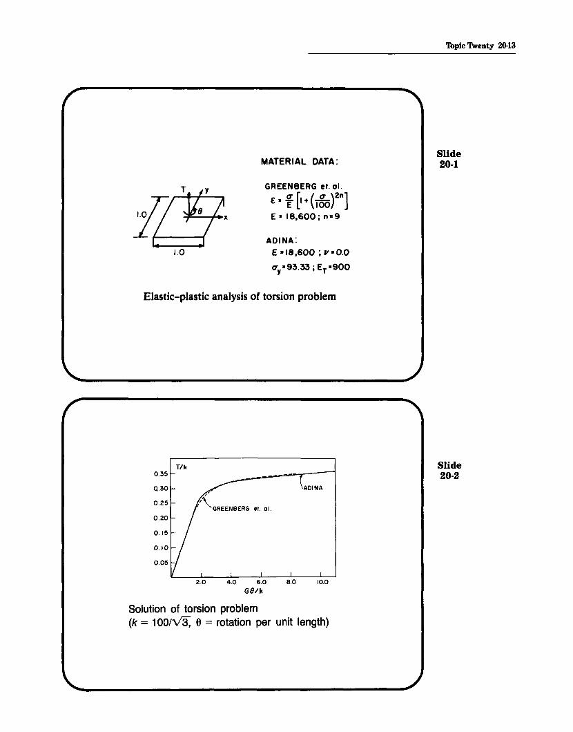
MATERIAL DATA:
GREENBERG et. a!.
E= [ [I + (lgo)2n]E = IB,600i n=9
ADINA:E =18,600; 11=0.0
CTy=93.33 i ET=900
'Ibpic Twenty 20-13
Slide20-1
Elastic-plastic analysis of torsion problem
T/k0.35
2.0 4.0 6.0G8/k
ADINA
10.0
Slide20-2
Solution of torsion problem(k = 1OO/~ 0 = rotation per unit length)

20-14 Beam, Plate and Shell Elements - Part II
Transparency20-19
Transparency20-20
Use of the isoparametric beam andshell elements
• The elements can be programmed foruse with different numbers of nodes- For the beam,
2, 3 or 4 nodes- For the shell,
4, 8, 9, "', 16 nodes
• The elements can be employed foranalysis of moderately thick structures(shear deformations are approximatelytaken into account).
• The elements can be used foranalysis of thin structures - but thenonly certain elements of thosementioned above should be used.
For shells: Use only the 16-nodeelement with 4 x 4 Gaussintegration over the mid-
X3 surface.
r
integration point

For beams:
Use 2-node beam element with 1-pointGauss integration along r-direction,
orUse 3-node beam element with 2-pointGauss integration along r-direction,
orUse 4-node beam element with 3-pointGauss integration along r-direction.
The reason is that the other elementsbecome overly (and artificially) stiffwhen used to model thin structures andcurved structures.
Two phenomena occur:
• Shear locking
• Membrane locking
Topic Twenty 20-15
Transparency20-21
Transparency20-22

20-16 Beam, Plate and Shell Elements - Part II
Transparency20-23
Transparency20-24
• The 2-, 3- and 4-node beamelements with 1-, 2- and 3-point Gaussintegration along the beam axes donot display these phenomena.
• The 16-node shell element with 4 x 4Gauss integration on the shell midsurface is relatively immune to shearand membrane locking (the elementshould not be distorted for bestpredictive capability).
• To explain shear locking, consider a2-node beam element with exactintegration (2-point Gauss integrationcorresponding to the r-direction).
r=-1 r=OTransverse displacement:
1 1w = 2" (1 - r) W1 + 2" (1 + r) W2
Section rotation:1 1
~ = 2" (1 - r) 61 + 2" (1 + r) 62
neutral axis7
I,
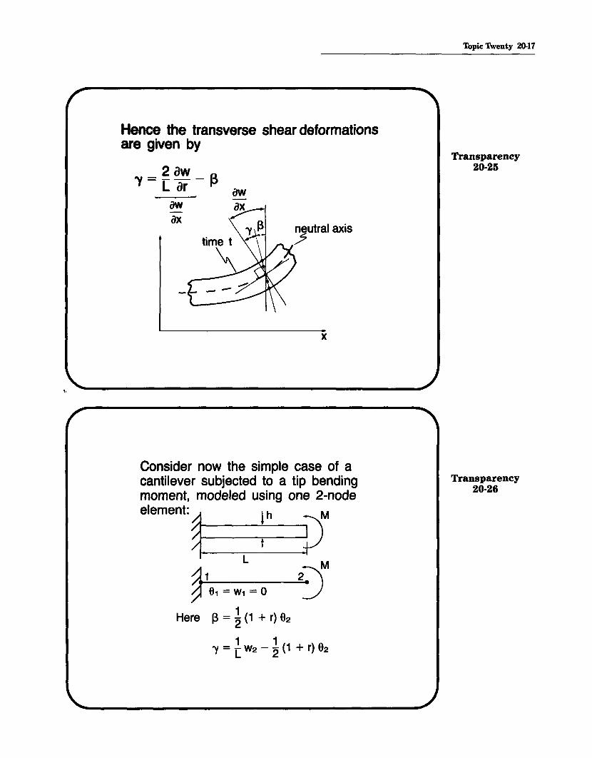
Hence the transverse shear deformationsare given· by
"Y=f~-~awax
x
Consider now the simple case of acantilever subjected to a tip bendingmoment, modeled using one 2-node
element:~. Ih pML
@16, = w, = 0 2)M
1Here 13 = "2 (1 + r) 62
1 1'Y = [w2 - "2 (1 + r) 92
Topic Twenty 20-17
Transparency20-25
Transparency20-26

20-18 Beam, Plate and Shell Elements - Part II
Transparency20-27
Transparency20-28
We observe:
• Clearly, 'Y cannot be zero at all pointsalong the beam, unless 62 and W2
are zero. But then also ~ would bezero and there would be no bendingof the beam.
• Since for the beam- bending strain energy oc: h3
- shear strain energy oc: hany error in the shear strains (due tothe finite element interpolationfunctions) becomes increasingly moredetrimental as h becomes small.
• For the cantilever example, theshear strain energy should be zero.As h decreases, the relative error inthe shear strain increases rapidlyand in effect, introduces an artificialstiffness that makes the model"lock."
h/L finite element solutionL = 100 Oanalytical (exact integration)
-9.6 x 10⁻⁷ 3.2 X 10-70.50
0.10 1.2 x 10⁻⁴ 2.4 X 10⁻⁶
0.01 1.2 x 10⁻¹ 2.4 X 10⁻⁵

• Although we considered only oneelement in the solution, the sameconclusion of locking holds for anassemblage of elements.
~ ••• \ ••••••• ?)Meach element should carrya constant bending moment
Example: Beam locking study
~ ......... JMn equally spaced elements
L=10 mSquare cross-section, height = 0.1 mTwo-node beam elements,full integration
Topic Twenty 20-19
Transparency20-29
Transparency20-30

20-20 Beam, Plate and Shell Elements - Part II
Transparency20-31
Plot tip deflection as a function of thenumber of elements:
32.00 Beam theory solution
10.008.006.004.002.00'10'
~Finiteelement solution(2-node beam elements,
full integration)
I~Height of element = Length of element
o+--;.I_.---...,.--~~--r---r--r----r----.-.o
8.00
24.00
16.00Tip
deflection(m)
Number of elements
Transparency20-32 Beam theory solution
0.3 1------------
Tipdeflection
(m)
0.2
0.1Finite element solution
\10 20 30
Number of elements

A remedy for the 2-node beam element is touse only 1-point Gauss integration (along thebeam axis).This corresponds to assuming a constanttransverse shear strain, (since the shear strainis only evaluated at the mid-point of the beam).
The bending energy is still integrated accurately
(since : is correctly evaluated).
h/L finite element solutionL = 100 6analytical (1-point integration)
0.50 9.6 x 10⁻⁷ 9.6 X 10⁻⁷
0.10 1.2 x 10⁻⁴ 1.2 X 10⁻⁴
0.01 1.2 x 10⁻¹ 1.2 X 10⁻¹
• The 3- and 4-node beam elements evaluatedusing 2- and 3-point integration are similarlyeffective.
• We should note that these beam elementsbased on "reduced" integration are reliablebecause they do not possess any spuriouszero energy modes. (They have only 6 zeroeigenvalues in 3-D analysis corresponding tothe 6 physical rigid body modes).
• The formulation can be interpreted as amixed interpolation of displacements andtransverse shear strains.
Topic Twenty 20-21
Transparency20-33
Transparency20-34

20-22 Beam, Plate and Shell Elements - Part II
Transparency20-35
Transparency20-36
• Regarding membrane-locking wenote that in addition to not exhibitingerroneous shear strains, the beammodel must also not contain erroneous mid-surface membrane strains inthe analysis of curved structures.
• The beam elements with reducedintegration also do not "membranelock~'
Consider the analysis of a curvedcantilever:

The exactly integrated 3-node beamelement, when curved, does containerroneous shear strains and erroneousmid-surface membrane strains. As aresult, when h becomes small, theelement becomes very stiff.
finite element finite elementsolution: 3-node solution: 3-node
h/R 9analytical element, 3-point element, 2-pointR = 100 (a = 45°) integration integration
0.50 7.5 x 10⁻⁷ 6.8 X 10⁻⁷ 7.4 X 10⁻⁷
0.10 9.4 x 10⁻⁵ 2.9 X 10⁻⁵ 9.4 X 10⁻⁵
0.01 9.4 x 10⁻² 4.1 X 10⁻⁴ 9.4 X 10⁻²
• Similarly, we can study the use of the4-node cubic beam element:
finite element finite elementh/R 9anaJytical solution: 4-node solution: 4-node
R = 100 (a = 45°) element, 4-point element, 3-pointintegration integration
0.50 7.5 x 10⁻⁷ 7.4 X 10⁻⁷ 7.4 X 10⁻⁷
0.10 9.4 x 10⁻⁵ 9.4 X 10⁻⁵ 9.4 X 10⁻⁵
0.01 9.4 x 10⁻² 9.4 X 10⁻² 9.4 X 10⁻²
We note that the cubic beam elementperforms well even when using fullintegration.
Topic Twenty 20-23
Transparency20-37
Transparency20-38

20-24 Beam, Plate and Shell Elements - Part II
Transparency20-39
Transparency20-40
Considering the analysis of shells, thephenomena of shear and membranelocking are also present, but thedifficulty is that simple "reduced"integration (as used for the beamelements) cannot be recommended,because the resulting elements containspurious zero energy modes.
For example, the 4-node shell elementwith 1-point integration contains 6spurious zero energy modes (twelvezero eigenvalues instead of only six).
Such spurious zero energy modes canlead to large errors in the solution that- unless a comparison with accurateresults is possible - are not known andhence the analysis is unreliable.

• For this reason, only the 16-nodeshell element with 4 x 4 Gaussintegration on the shell mid-surfacecan be recommended.
• The 16-node element should, asmuch as possible, be used with theinternal and boundary nodes placedat their ~rd points (without internalelement distortions). This way theelement performs best.
• Recently, we have developedelements based on the mixedinterpolation of tensorial components.
• The elements do not lock, in shear ormembrane action, and also do notcontain spurious zero energy modes.
• We will use the 4-node element,referred to as the MITC4 element, insome of our demonstrative samplesolutions.
Topic 1\venty 20-25
Transparency20-41
Transparency20-42
20-26 Beam, Plate and Shell Elements - Part II
Transparency20-43
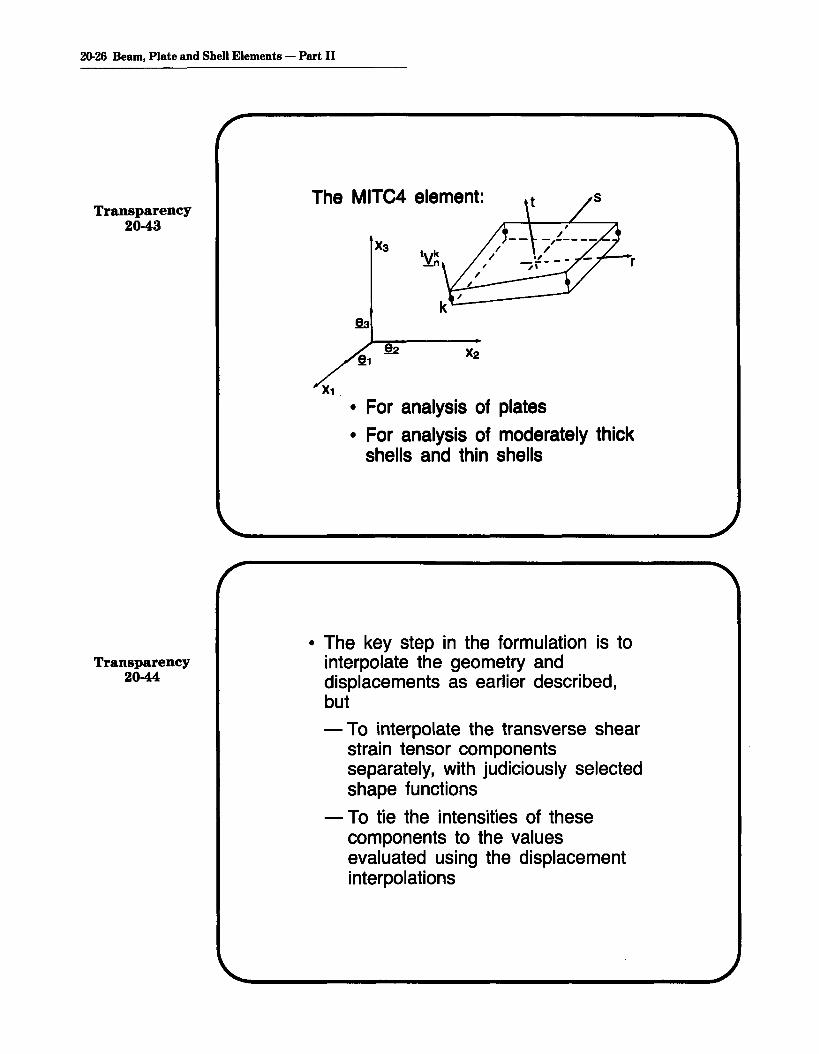
The MITC4 element:
r
Transparency20-44
• For analysis of plates
• For analysis of moderately thickshells and thin shells
• The key step in the formulation is tointerpolate the geometry anddisplacements as earlier described,but
- To interpolate the transverse shearstrain tensor componentsseparately, with judiciously selectedshape functions
- To tie the intensities of thesecomponents to the valuesevaluated using the displacementinterpolations

rt transverse shear strain tensorcomponent interpolation
R?77,evaluated from
displacement interpolations
st transverse shear strain tensorcomponent interpolation
s
Topic Twenty 20-27
Transparency20-45
The MITC4 element
• has only six zero eigenvalues (nospurious zero energy modes)
• passes the patch test
What do we mean by the patch test?The key idea is that any arbitrarypatch of elements should be able torepresent constant stress conditions.
Transparency20-46

20-28 Beam, Plate and Shell Elements - Part II
THE PATCH TESTTransparency
20-47• We take an· arbitrary patch of
elements (some of which are geometrically distorted) and subjectthis patch to- the minimum displacementlrotn.
boundary conditions to eliminatethe physical rigid body modes,and
- constant boundary tractions,corresponding to the constantstress condition that is tested.
Transparency20-48 • We calculate all nodal point
displacements and element stresses.
The patch test is passed if the calculated element internal stresses andnodal point displacements are correct.

E=2.1 X 10⁶
v=0.3thickness = 0.01
.tX_2 (10,10)
r10
L_------..... (10,0)
(0,0) 1f-----10----.\ X1
PATCH OF ELEMENTS CONSIDERED
t
-0- 01
MEMBRANE TESTS
t
101 0 -0-!
BENDING/TWISTING TESTS
Topic 1\venty 20-29
Transparency20-49
Transparency20-50

20·30 Beam, Plate and Shell Elements - Part II
Transparency20-51
Example: Spherical shell
radius = 10.0thickness = 0.04E=6.825x 10⁷
v=0.3
Transparency20-52
Selection of director vectors:• One director vector is generated
for each node.
• The director vector for each nodeis chosen to be parallel to theradial vector for the node.
• In two dimensions:
vector
~-------x

Selection of displacement boundaryconditions:
• Consider a material fiber that isparallel to a director vector. Then, ifthis fiber is initially located in the x-zplane, by symmetry this fiber mustremain in the x-z plane after the shellhas deformed:
Topic 1\venty 20-31
Transparency20-53
zmaterial ~ .,-......fiber at time 0 _tv~
material fiberat time t
x
Finite element mesh: Sixty-four MITC4 elements Transparency20-54
Symmetricboundary conditions
(y = 0)
~
/1.0
z
xAySymmetric
boundary conditions~(x=O)
Uz = 0 (to prevent rigid-body motion)

20-32 Beam, Plate and Shell Elements - Part II
Transparency20-55
This condition is applied to each nodeon the x-z plane as follows:
z
Transparency20-56
• A similar condition is applied tonodes initially in the y-z plane.
• These boundary conditions aremost easily applied by makingeuch node in the x-z or y-zplane a 6 degree of freedomnode. All other nodes are 5degree of freedom nodes.
• To prevent rigid body translationsin the z-direction, the z displacement of one node must be setto zero.

zL y
Linear elastic analysis results:
• Displacement at point of loadapplication is 0.0936 (analyticalsolution is 0.094).
• Pictorially,
Exam~: Analysis of an open (five-sided)box:
Box is placed open-side-down/Add on africtionless surface.~ Uniform pressure
Box is modeledusing shellelements
rigid,frictionlesssurface
Topic 1\venty 20-33
Transparency20-57
Transparency20-58

20-34 Beam, Plate and Shell Elements - Part II
Transparency20-59
Modeling of the box with shellelements:
- Choose initial director vectors.
- Choose 5 or 6 degrees of freedomfor each node.
- Choose boundary conditions.
Transparency20-60
- Instead of input of director vectors,one for each node, it can be moreeffective to have ADINA generatemid-surface normal vectors.
- If no director vector is input for anode, ADINA generates for eachelement connected to the node anodal point mid-surface normalvector at that node (from theelement geometry).
- Hence, there will then be as manydifferent nodal point mid-surfacenormal vectors at that node asthere are elements connected tothe node (unless the surface isflat).

Nodal point mid-surface normal vectors for the box:
- We use the option of automatic generation ofelement nodal point mid-surface normal vectors.
- At a node, not on an edge, the result is onemid-surface normal vector (because the surfaceis flat).
- At an edge where two shell elements meet,two mid-surface normal vectors are generated(one for each element). ---s:;-- one mid-surface
normal vectorused at this node
two mid-surfacenormal vectorsused at this node
Degrees of freedom:
Topic Twenty 20-35
Transparency20-61
Transparency20-62
6 degreesof freedom no rotational
stiffness forthis degreeof freedom

20-36 Beam, Plate and Shell Elements - Part II
Note added in preparation ojstudy-guideIn the new version of ADINA (ADINA 84 with an update inserted, or ADINA 86)
the use of the 5 or 6 shell degree of freedom option has been considerably automatized:- The user specifies whether the program is to use 5 or 6 degrees of freedom at each
shell mid-surface node NIGL(N).EQ.O-6 d.o.f. with the translations and rotations corresponding to the
global (or nodal skew) systemIGL(N).EQ.l-+5 d.o.f. with the translations corresponding to the global (or nodal
skew) system but the rotations corresponding to the vectors VIand V2
- The user (usually) does not input any mid-surface normal or director vectors. Theprogram calculates these automatically from the element mid-surface geometries.
- The user recognizes that a shell element has no nodal stiffness corresponding tothe rotation about the mid-surface normal or director vector. Hence, a shell midsurface node is assigned 5 d.o.f. unless
a shell intersection is considereda beam with 6 d.o.f. is coupled to the shell nodea rotational boundary condition corresponding to a global (or skew) axis is to beimposeda rigid link is coupled to the shell node
For further explanations, see the ADINA 86 users manual.
-: admissible-*-: deleted
Displacement boundary conditions:Box is shown open-side-up.
f
+representative nodenot at a corner
Transparency20-63

Consider a linear elastic static analysisof the box when a uniform pressureload is applied to the top.We use the 128 element mesh shown(note that all hidden lines are removedin the figure): lv
x
4-nodeshellelement
We obtain the result shown below(again the hidden lines are removed):
• The displacements in this plot arehighly magnified.
Topic 1\venty 20-37
Transparency20-64
Transparency20-65
z
~vx

20-38 Beam, Plate and Shell Elements - Part II
Slide20-3
o
.,. ERROR -5IN CENTER
DISPLACFMENT
-10
-15
.--~II "Q3 L[Eg:• N"2
I--
2N
4 6
Slide20-4
Simply-supported plate under uniform pressure,Uh = 1000
o11~t==t==+====t====t1
Of. ERROR -51---+---+---...,1---+---+--+----1IN CENTER
OISPLACEMENT
-101---+---+---+--+---+---+--1
-15 L...-_....L..._~_--J,__~_....L..._......I.._---1
2 N 4 6
Simply-supported plate under concentrated loadat center, Uh = 1000

o
.,. ERROR -5IN CENTER
DISPLACEMENT
-10
-15
~~
Thpic 1\venty 20-39
Slide20-5
2N
4 6
Clamped plate under uniform pressure, Uh = 1000
~-~
~
V/
/
o
"to ERROR -5IN CENTER
DISPLACEMENT
-10
-152
N4 6
Slide20-6
Clamped plate under concentrated load atcenter. Uh = 1000
20-40 Beam, Plate and Shell Elements - Part II
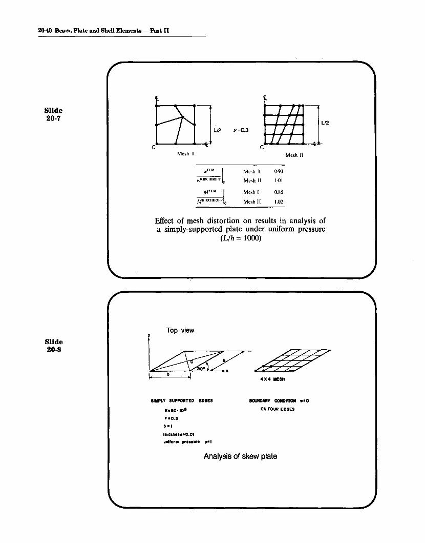
Slide20-7
Mesh I
/I =0.3
Mesh 1\
M~"M IMKIRClIIIOI.".' C
Mesh I
Mesh II
Mesh I
Mesh"
0·93
Hli
0.85
1.02
Slide20-8
Effect of mesh distortion on results in analysis ofa simply-supported plate under uniform pressure
(L/h = 10(0)
Top viewr
SIMPLY SUPPORTED EDIES
E.50 0 10·
~"'0.5
b .1
thickn...·O.OI
unlf.'1Il pr•••ur. p"'1
IlOUNDARY CONDmON ••0
ON FOUR EDGES
Analysis of skew plate

MESH .FEM;' MO FEM~ MO FEM AMOe ·e Mmax Mmax Mmln Mmln
4X4 0.879 0.873 0.852
8X8 0.871 0.928 0.922
16X 16 0.933 0.961 0.919
32X32 0.985 0.989 0.990
Solution of skew plate at point C usinguniform skew mesh
2 X 2 MESH
MESH FEM/ wMO FEM/ MO FEM/ MO"c c Mmox Mmex Mmm Mmm
2X2 0.984 0.717 0.602
4 X4 0.994 0.935 0.878
Solution of skew plate using a more effective mesh
Topic Twenty 20-41
Slide20-9
Slide20·10

20-42 Beam, Plate and Shell Elements - Part II
Slide20-11
11----- L ----.I/-r
TL = 12 INI = 1/12 IN 4
A = I IN2
E = 3.0x 10⁷
PSI11= 0M = CONC E NTRATE D
END MOMENT
Large displacement analysis of a cantilever
1.0
Slide20-12
RATIOS
u/L, oIL, </>/2"
0.2
0.4 0.5MOMENT PARAMETER '1 = ML/2"E I
Response of cantilever

1.0__ ANALYT. SOLN.
u 0.8Lv w/L
Vw 0.6 V
L Z 7L
v.
<t>9J o u/L
211'
TWO 4-NODE ELEMENT MODEL
ML27i'IT'
Large displdcement/rotation analysis of acanti 1ever
Topic 'l\venty 20-43
Slide20-13
Slide20-14
~ 0.6LZZ7THREE 4- NODE ELEMENT MODEL
..ILL 08
V w/Lv.
v.
0.1 0.2 0.3
ML27rEI
20-44 Beam, Plate and Shell Elements - Part II
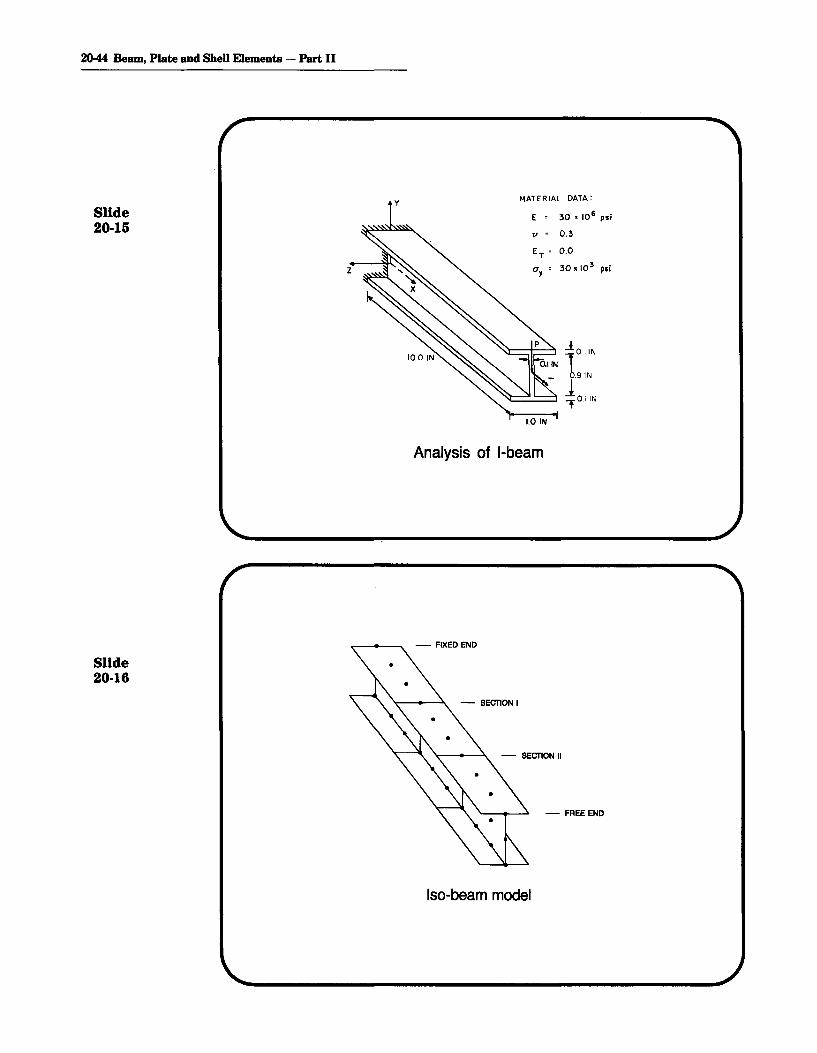
MATERIAL DATA:
Slide E 30 , 10' psi
20-15"
0 0.3
E 0 0.0T
Z a 0 30 '10 3 psiy
...!1D'IN
T 0.91N
iOi'N1,0 IN
Analysis of I-beam
Slide20-16
- FREE END
Iso-beam model

Shell model
Topic 1\venty 20-45
Slide20-17
y
..-:
,
f-- -xT
_".~~
----8. Z
y
Slide20-18
I--- 50 IN---lI- --IO.OIN---I
I-beam

2046 Beam, Plate and Shell Elements - Part II
~SO-beammodel
MERCHANT'SUPPER BOUND
"SAND HEAP"~
;Shellmodel
.-....&._--------~
200
100
300
T IN-LBS
Slide20-19
o 0.10 020 0.308. RADIANS
0.40
Rotation of I-beam about X -axis for increasingtorsional moment.
Slide20-20
IXI UNI'ORM MESH USEDTO REPRESENT AREA ABCD
E =21,0001/=0
Er O
aY=4.2
L 0:15,200
R 0: 7,600
1/)= 40
fhickn.u=76
Large deflection elastic-plastic analysis of a cylindrical shell
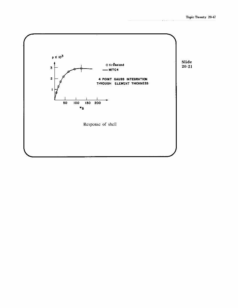
2
o Kr8keland
-MITC4
4 POINT GAUSS INTEGRATIONTHROUGH ELEMENT THICKNESS
50 100 150 200
we
Response of shell
Topic 1\venty 20-47
Slide20-21

MIT OpenCourseWare http://ocw.mit.edu
Resource: Finite Element Procedures for Solids and Structures Klaus-Jürgen Bathe
The following may not correspond to a particular course on MIT OpenCourseWare, but has been provided by the author as an individual learning resource.
For information about citing these materials or our Terms of Use, visit: http://ocw.mit.edu/terms.