bcdv.1002. from index 20
TRANSCRIPT

Service Documentation
Service Manual No. 33/2009 LAK/KDT-fuz/20.11.09
Page 1/12 33200900SM_gb
After Sales Service International
Appliance Documentation
BCDv.1002. from Index 20
Drinks refrigerator, ventilated with display

Service Manual No. 33/2009 BCDv 1002
Page 2/12
Contents
1.0 Operating and control elements............................................................................................. 3
2.0 Functions at a glance.............................................................................................................. 3
3.0 Description of appliance......................................................................................................... 4 3.1 Schematic diagram.................................................................................................................... 4
4.0 Main components and their functions ................................................................................... 5 4.1 Electrical components and functions .......................................... Error! Bookmark not defined.
5.0 Refrigeration circuit ................................................................................................................ 6
6.0 Special Features...................................................................................................................... 7 6.1 Water Evaporator ...................................................................................................................... 7 6.2 Wall-mounting ........................................................................................................................... 7
6.3 Air Supply exhaust……………………………………...………………………………….……………8
7.0 Parts replacement ................................................................................................................... 9 7.1 Replacing the thermostat........................................................................................................... 9 7.1.2 Removing the capillary tube and thermostat………………..……………………………...….9
7.2 Replacing the interior fan……………………………………………………………………………...10
7.3 Replacing the compressor fan ................................................................................................ 11
8.0 Technical data ....................................................................................................................... 12

Service Manual No. 33/2009 BCDv 1002
Page 3/12
1.0 Operating and control elements
1 Temperature controller 2 Door contact switch 3 Switch for interior light and display
2.0 Functions at a glance
Control: Thermostat
Temperature display: None
Temperature range: +2°C to +12°C
Defrosting Automatic
Interior lighting: Interior light, display light
Climate rating: SN (+10°C to 32°C)
Compressor: Standard
Door: Lockable, interchangeable door hinges, self-closing mechanism

Service Manual No. 33/2009 BCDv 1002
Page 4/12
3.0 Description of appliance
The BCDv 1002 is a drink chiller where by heat is withdrawn from the interior by means of a freely suspended rear wall evaporator. This drink chiller has an interior fan that provides a uniform temperature distribution and a more rapid cooling in the interior. It runs permanently and is switched off only when the door is open. Defrosting takes place automatically, each time when the compressor is at standstill. The water is collected in an evaporation tray at the rear and is evaporated with the aid of hot gas heating. The appliance can be placed on the counter or mounted to the wall.
3.1 Schematic diagram
Compressor Fan
Panel
Interior Fan
Rear Wall Evaporator
Air Sensor Position
Evaporator Tray
Compressor
Display Cover

Service Manual No. 33/2009 BCDv 1002
Page 5/12
4.0 Electrical components and functions
Functions
Temperature control: Position : Underside of the display
Function : - Thermostat with air sensor. Switches the compressor ON and OFF
- Appliance OFF at step ‘0’
Setting Range refrigerator compartment :
+2° C to 12 °C
Light switch (in appliances with glass door):
Position : Underside of the display
Function : switches light On and OFF
Door contact switch: Position: Underside of the display
Function: Switching signal when:
door closed: fan ON
door open: fan OFF
Compressor fan: Position : Behind the display
Function : Operates in parallel with compressor
Interior fan : Position : In the interior, top back
Function : Operates permanently as soon as the appliances is switched ON. The fan switches OFF when door is open
Interior light and display light :
Position : On the inner liner ceiling and behind the display, respectively
Function : On when the poser plug is connected and the light is switched ON
Sensors
Air sensor: Position: On the compartment liner, behind the evaporator. Air sensor is not to be in contact with any surface. It hangs freely to detect surrounding air temperature. When it detects the surrounding air as high temperature, it will signal the compressor to turn off. If it detects low temperature, otherwise will happen.
Loads
Compressor: Type: Standard
Function: ON: Air sensor switch-on value. OFF: Air sensor switch-off value.
Note : parallel with thermostat air sensor

Service Manual No. 33/2009 BCDv 1002
Page 6/12
5.0 Refrigeration circuit
Compressor
Type: Standard
Evaporator
Type: Rear wall evaporator
Type of installation: Suspended freely
Injection point: Top
Flow sequence: From top to bottom
Condenser
Type: Wire condenser
Refrigerant
Type: R600a

Service Manual No. 33/2009 BCDv 1002
Page 7/12
6.0 Special Features
6.1 Water Evaporator
The water is conducted out of the interior and collected in a “channel-like” evaporation tray. The water there is evaporated by the hot gas duct.
Figure 6.1/1
6.2 Wall-mounting
This drink cooler could be mounted to the wall. There are 2 openings at the rear for this purpose.
Figure 6.2/1
Evaporation tray
Evaporation tray
Opening for mounting purpose

Service Manual No. 33/2009 BCDv 1002
Page 8/12
6.3 Air supply exhaust
The compressor and condenser are placed behind the display and are dynamically cooled. Air is sucked in through the supply inlet while hot air is released from the exhaust. In any instance, there must be at least 20 cm clearance above the appliance.
Figure 6.3/1
Air exhaust
Air exhaust

Service Manual No. 33/2009 BCDv 1002
Page 9/12
7.0 Parts replacement
7.1 Replacing the thermostat
Detaching the fan cover
The fan cover is secured by 4 screws on the inner liner. Before removing the screws, remove the stopper, disconnect the fan cable then remove the cover together with the fan.
Figure 7.1.1/1
7.1.2 Removing the capillary tube and thermostat
Evaporator:
After removing the fan cover, free the evaporator and turn it to the side. The capillary tube could be seen clip to the back body of the BCDv.
Fig. 7.1.2/1
Air Sensor
Service Manual No. 33/2009 BCDv 1002
Page 10/12
7.2 Replacing the interior fan
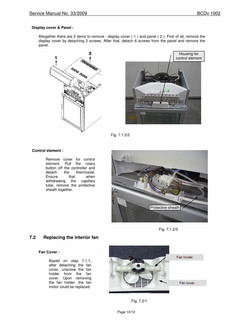
Display cover & Panel :
Altogether there are 2 items to remove : display cover ( 1 ) and panel ( 2 ). First of all, remove the display cover by detaching 2 screws. After that, detach 6 screws from the panel and remove the panel.
Fig. 7.1.2/2
Control element :
Remove cover for control element. Pull the rotary button off the controller and detach the thermostat. Ensure that when withdrawing the capillary tube, remove the protective sheath together.
Fig. 7.1.2/3
Fan Cover :
Based on step 7.1.1, after detaching the fan cover, unscrew the fan holder from the fan cover. Upon removing the fan holder, the fan motor could be replaced.
Fig. 7.2/1
Housing for control element
Protective sheath

Service Manual No. 33/2009 BCDv 1002
Page 11/12
7.3 Replacing the compressor fan
In order to replace the compressor fan, the panel has to be removed first. Refer fig 7.3/1
Fig 7.3/1
Compressor fan
Compressor fan : Remove two screws from the bracket of the compressor fan. After removing the screws, the fan motor could be replaced.
Screw (x2)

Service Manual No. 33/2009 BCDv 1002
Page 12/12
8.0 Technical data
Item Technical data Value
Thermostat :
Warm ON : Warm OFF : Cold ON : Cold OFF :
+15.3 °C -2.5 °C +3.3 °C -3.6 °C
Interior fan :
Wattage : Voltage : Speed :
10 Watts 220-240 volts 50/60Hz 1800 ± 100 rpm
Compressor Fan :
Wattage : Voltage : Speed :
10 Watts 220-240 volts 50/60Hz 1800 ± 100 rpm
Display light : Wattage : 8 Watts ( fluorescent lamp )
Interior light : Wattage : 8 Watts ( fluorescent lamp )