bcdi pilot technical reference guide
TRANSCRIPT

BCDI Pilot Technical Reference Guide
Software Version 6.0
Reference Guide Edition 4


© China Mobile Group Design Institute Co. Ltd 2007 All rights reserved
BCDI Pilot is a product co-developed between China Mobile Group Design Institute Co. Ltd. and AIRCOM International Ltd.
China Mobile Group Design Institute Co. Ltd. and AIRCOM International Ltd separately reserve their rights.
ADVANTAGE, AIRCOM, ARRAY WIZARD, ASSET, CONNECT, DATASAFE, ENTERPRISE, NEPTUNE, OPTIMA, QUALITA, RANOPT, TARGET and WEBWIZARD are recognised trademarks of AIRCOM International.
Microsoft Excel , .NET™, Microsoft Office, Outlook , Visual Basic Windows®,
Windows XP™, Windows Vista™ and Word are trademarks of the Microsoft Corporation.
Other product names are trademarks of their respective companies.
This documentation is protected by copyright and contains proprietary and confidential information. No part of the contents of this documentation may be disclosed, used or reproduced in any form, or by any means, without the prior written consent of China Mobile Group Design Institute Co. Ltd.
Although China Mobile Group Design Institute Co. Ltd. has collated this documentation to reflect the features and capabilities supported in the software products, the company makes no warranty or representation, either express or implied, about this documentation, its quality or fitness for a particular customer purpose. Users are solely responsible for the proper use of BCDI Pilot software and the application of the results obtained.
An electronic version of this document exists.


BCDI Pilot Technical Reference Guide Page 5 Version 6.0
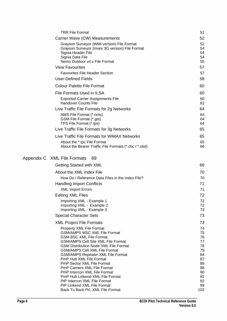
Contents
Appendix A Map Data File Formats 11
About the Map Data Format Used 11
Height Data Format 12
Clutter Data 13
Configuring Map Backdrops 14
Configuring Map Backdrops for a Single Layer Type 14 Configuring Map Backdrops for Multiple Layer Types 15 Configuring Map Backdrops for Multiple Layer Types with Multiple Resolutions 16 About the File Format for Map Backdrops Index Files 18 Using Map Backdrops Effectively 19
Vector Data 20
About the Vector Index.xml File Format 21 About TAB Files for Building Vectors 22 Using Multiple TAB-FILE Entries in the Same TAB-FILE-LIST 24 Example Vector Index.xml File 26
Building Raster Data 27
Text Data 27
Appendix B BCDI Pilot File Formats 29
Import and Export File Formats 30
BCDI Pilot Export File Format 30 BCDI Pilot XML Export File Format 30 3GPP XML File Formats 31 GSM Import 36 Properties Export and Import File Format 39 Equipment Export and Import File Format 39 Coverage Arrays Import and Export 40
Coverage and Interference Arrays 40
Coverage Array Header Section - Version 1 41 Coverage Array Header Section - Version 2 41 Structure of Array Data File 42
Simulation Array File Formats 44
3ga File Format 45
Interference Tables 47
Header Section 47 Data Section 47 Example Interference Table 48
Neighbours 49
Predictions 49
Traffic Raster 50
TRI File Format 50
Page 6 BCDI Pilot Technical Reference Guide Version 6.0
TRR File Format 51
Carrier Wave (CW) Measurements 52
Grayson Surveyor (WMI version) File Format 52 Grayson Surveyor (Invex 3G version) File Format 54 Signia Header File 54 Signia Data File 54 Nemo Outdoor v4.x File Format 55
View Favourites 57
Favourites File Header Section 57
User-Defined Fields 58
Colour Palette File Format 60
File Formats Used in ILSA 60
Exported Carrier Assignments File 60 Handover Counts File 62
Live Traffic File Formats for 2g Networks 64
NMS File Format (*.nms) 64 GSM File Format (*.gts) 64 TPS File Format (*.tps) 64
Live Traffic File Formats for 3g Networks 65
Live Traffic File Formats for WiMAX Networks 65
About the *.tpc File Format 65 About the Bearer Traffic File Formats (*.cbc / *.cbd) 66
Appendix C XML File Formats 69
Getting Started with XML 69
About the XML Index File 70
How Do I Reference Data Files in the Index File? 70
Handling Import Conflicts 71
XML Import Errors 71
Editing XML Files 72
Importing XML - Example 1 72 Importing XML - Example 2 72 Importing XML - Example 3 73
Special Character Sets 73
XML Project File Formats 73
Property XML File Format 74 GSM/AMPS MSC XML File Format 75 GSM BSC XML File Format 76 GSM/AMPS Cell Site XML File Format 77 GSM Distribution Node XML File Format 78 GSM/AMPS Cell XML File Format 79 GSM/AMPS Repeater XML File Format 84 PmP Hub XML File Format 87 PmP Sector XML File Format 88 PmP Carriers XML File Format 88 PmP Intercon XML File Format 90 PmP Hub Linkend XML File Format 92 PtP Intercon XML File Format 92 PtP Linkend XML File Format 99 Back To Back PrL XML File Format 102
BCDI Pilot Technical Reference Guide Page 7 Version 6.0
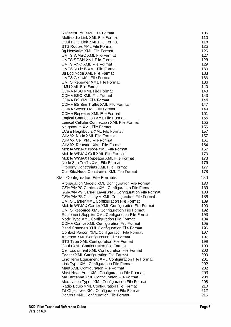
Reflector PrL XML File Format 106 Multi-radio Link XML File Format 110 Dual Polar Link XML File Format 118 BTS Routes XML File Format 125 3g Networks XML File Format 126 UMTS WMSC XML File Format 127 UMTS SGSN XML File Format 128 UMTS RNC XML File Format 129 UMTS Node B XML File Format 130 3g Log Node XML File Format 133 UMTS Cell XML File Format 133 UMTS Repeater XML File Format 136 LMU XML File Format 140 CDMA MSC XML File Format 143 CDMA BSC XML File Format 143 CDMA BS XML File Format 144 CDMA BS Sim Traffic XML File Format 147 CDMA Sector XML File Format 149 CDMA Repeater XML File Format 151 Logical Connection XML File Format 155 Logical Cellular Connection XML File Format 155 Neighbours XML File Format 156 LCSE Neighbours XML File Format 157 WiMAX Node XML File Format 157 WiMAX Cell XML File Format 161 WiMAX Repeater XML File Format 164 Mobile WiMAX Node XML File Format 167 Mobile WiMAX Cell XML File Format 170 Mobile WiMAX Repeater XML File Format 173 Node Sim Traffic XML File Format 176 Property Constraints XML File Format 177 Cell Site/Node Constraints XML File Format 178
XML Configuration File Formats 180
Propagation Models XML Configuration File Format 180 GSM/AMPS Carriers XML Configuration File Format 183 GSM/AMPS Carrier Layer XML Configuration File Format 183 GSM/AMPS Cell Layer XML Configuration File Format 186 UMTS Carrier XML Configuration File Format 189 Mobile WiMAX Carrier XML Configuration File Format 190 UMTS Resource XML Configuration File Format 192 Equipment Supplier XML Configuration File Format 193 Node Type XML Configuration File Format 194 CDMA Carrier XML Configuration File Format 195 Band Channels XML Configuration File Format 196 Contact Person XML Configuration File Format 197 Antenna XML Configuration File Format 197 BTS Type XML Configuration File Format 199 Cabin XML Configuration File Format 199 Cell Equipment XML Configuration File Format 200 Feeder XML Configuration File Format 200 Link Term Equipment XML Configuration File Format 201 Link Type XML Configuration File Format 202 Mast XML Configuration File Format 202 Mast Head Amp XML Configuration File Format 203 MW Antenna XML Configuration File Format 204 Modulation Types XML Configuration File Format 208 Radio Equip XML Configuration File Format 210 T/I Objectives XML Configuration File Format 212 Bearers XML Configuration File Format 215

Page 8 BCDI Pilot Technical Reference Guide Version 6.0
Services XML Configuration File Format 219 EV-DO DL Parameters XML Configuration File Format 222 Terminal Types XML Configuration File Format 224 Clutter Parameters XML Configuration File Format 229 BCF Types XML Configuration File Format 229 Frequency Hopping Diversity Gain XML Configuration File Format 230 CI BER Conversion XML Configuration File Format 231 Channel To Transceiver Setup XML Configuration File Format 232 GPRS Data Throughput XML Configuration File Format 235 EGPRS Data Throughput XML Configuration File Format 237 HSCSD Data Throughput XML Configuration File Format 241 ECSD Data Throughput XML Configuration File Format 242 Timeslot Occupancy XML Configuration File Format 243 Back-to-Back Passive Repeater Link Near Field Effect XML Configuration File Format 245 Reflector Passive Repeater Link Near Field Effect XML Configuration File Format 245 HSDPA Coding Rates XML Configuration File Format 248 Compound Array Expressions XML Configuration File Format 250 Project Settings XML Configuration File Format 252
XML ADVANTAGE File Formats 253
ADVANTAGE Plans XML File Format 253 ADVANTAGE Details XML File Format 263 Global Design Targets XML File Format 265 Static Design Targets XML File Format 266 Monte Carlo Design Targets XML File Format 267 ADVANTAGE Clutter Parameters XML File Format 268 ADVANTAGE Vector Parameters XML File Format 270 Problem Cell Thresholds XML File Format 271 Problem Area Thresholds XML File Format 272 Action Combination Options XML File Format 276 Max Units/Actions XML File Format 276 Cost Function Weights XML File Format 277 Plan Rejection Options XML File Format 282
Appendix D Miscellaneous Vendor File Formats 287
Antenna Diagram File Format 287
Example Antenna File 288
Miscellaneous Vendors Carriers File Format 289
EET/Planet AMPS Carriers File Format 289 EET/Planet GSM Carriers File Format 290
Carrier Types Database File Formats 292
Miscellaneous Vendors Exceptions File Format 293
Miscellaneous Vendors Neighbours File Format 294
Example Neighbours File 295
Miscellaneous Vendors Site Database File Format 296
Planet 2.5 Site Database Format 297 Planet 2.8 Site Database File Format Header Records 297 Planet 2.8 Site Database File Format Data Records 298
BCDI Pilot Technical Reference Guide Page 9 Version 6.0
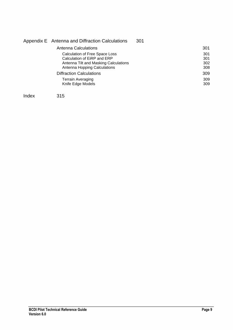
Appendix E Antenna and Diffraction Calculations 301
Antenna Calculations 301
Calculation of Free Space Loss 301 Calculation of EiRP and ERP 301 Antenna Tilt and Masking Calculations 302 Antenna Hopping Calculations 308
Diffraction Calculations 309
Terrain Averaging 309 Knife Edge Models 309
Index 315

Page 10 BCDI Pilot Technical Reference Guide Version 6.0
BCDI Pilot Technical Reference Guide Page 11 Version 6.0
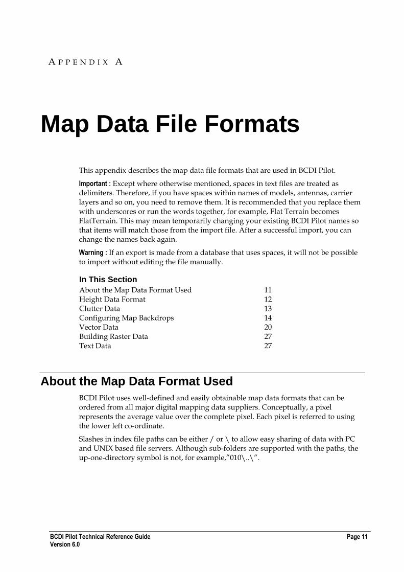
Map Data File Formats
This appendix describes the map data file formats that are used in BCDI Pilot.
Important : Except where otherwise mentioned, spaces in text files are treated as delimiters. Therefore, if you have spaces within names of models, antennas, carrier layers and so on, you need to remove them. It is recommended that you replace them with underscores or run the words together, for example, Flat Terrain becomes FlatTerrain. This may mean temporarily changing your existing BCDI Pilot names so that items will match those from the import file. After a successful import, you can change the names back again.
Warning : If an export is made from a database that uses spaces, it will not be possible to import without editing the file manually.
In This Section
About the Map Data Format Used 11 Height Data Format 12 Clutter Data 13 Configuring Map Backdrops 14 Vector Data 20 Building Raster Data 27 Text Data 27
About the Map Data Format Used
BCDI Pilot uses well-defined and easily obtainable map data formats that can be ordered from all major digital mapping data suppliers. Conceptually, a pixel represents the average value over the complete pixel. Each pixel is referred to using the lower left co-ordinate.
Slashes in index file paths can be either / or \ to allow easy sharing of data with PC and UNIX based file servers. Although sub-folders are supported with the paths, the up-one-directory symbol is not, for example,”010\..\”.
A P P E N D I X A
Page 12 BCDI Pilot Technical Reference Guide Version 6.0
Height Data Format
The height data - digital terrain model (DTM) is stored in a binary format where each element of the data represents the height above sea level in metres for a square area of, for example, 50m x 50m.
Index File
An ASCII text file called index.txt contains positional information about each binary height file. The file contains one row describing each height file. Relative path names can be incorporated within the filename to allow a structured approach to map data directory organisation.
Each row contains the following variables separated by a space:
Field Description
Filename Filename of DTM Height file
Eastmin Minimum Easting value (metres)
Eastmax Maximum Easting value (metres)
Northmin Minimum Northing value (metres)
Northmax Maximum Northing value (metres)
Square Size Size of each element of the height data (metres)
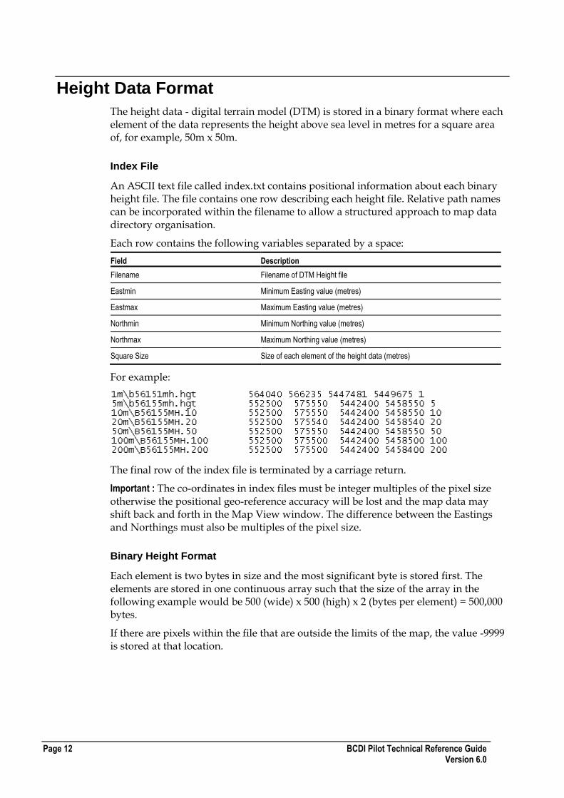
For example:
The final row of the index file is terminated by a carriage return.
Important : The co-ordinates in index files must be integer multiples of the pixel size otherwise the positional geo-reference accuracy will be lost and the map data may shift back and forth in the Map View window. The difference between the Eastings and Northings must also be multiples of the pixel size.
Binary Height Format
Each element is two bytes in size and the most significant byte is stored first. The elements are stored in one continuous array such that the size of the array in the following example would be 500 (wide) x 500 (high) x 2 (bytes per element) = 500,000 bytes.
If there are pixels within the file that are outside the limits of the map, the value -9999 is stored at that location.

BCDI Pilot Technical Reference Guide Page 13 Version 6.0
Clutter Data
The clutter data is stored in a binary format with each element of the data containing a code corresponding to a category of land usage for a square area of, for example, 50m x 50m.
Index File
An ASCII text file called index.txt contains positional information about each binary clutter file.
The file contains one row describing each clutter file. Relative path names can be incorporated within the filename to allow a structured approach to map data directory organisation.
Each row contains the following variables separated by a space:
Field Description
Filename Filename of Clutter file
The combination of index filename and path should not exceed 255 characters otherwise BCDI Pilot will truncate it and in the event of a duplication in the truncated names, BCDI Pilot will not add the duplicate.
Eastmin Minimum Easting value (metres)
Eastmax Maximum Easting value (metres)
Northmin Minimum Northing value (metres)
Northmax Maximum Northing value (metres)
Square Size Size of each element of the clutter data (metres)
For example:
The final row is terminated by a carriage return.
Important : The co-ordinates in index files must be integer multiples of the pixel size otherwise the positional geo-reference accuracy will be lost and the map data may shift back and forth in the Map View window.
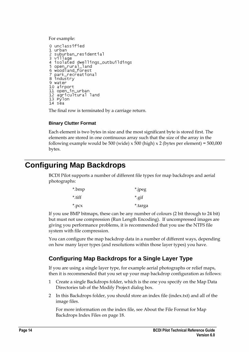
Menu File
In addition an ASCII text file called menu.txt contains a table relating the clutter codes stored in the binary clutter file with a textual description of the clutter category. Each line contains one code followed by one description space separated. This file must be in the same directory as the index file.
The textual description cannot be more than 32 characters long. If the descriptions are longer than this, they will be truncated. In the event of a duplication in the truncated descriptions, BCDI Pilot will warn you and will not add the duplicate.
Page 14 BCDI Pilot Technical Reference Guide Version 6.0
For example:
The final row is terminated by a carriage return.
Binary Clutter Format
Each element is two bytes in size and the most significant byte is stored first. The elements are stored in one continuous array such that the size of the array in the following example would be 500 (wide) x 500 (high) x 2 (bytes per element) = 500,000 bytes.
Configuring Map Backdrops
BCDI Pilot supports a number of different file types for map backdrops and aerial photographs:
*.bmp *.jpeg
*.tiff *.gif
*.pcx *.targa
If you use BMP bitmaps, these can be any number of colours (2 bit through to 24 bit) but must not use compression (Run Length Encoding). If uncompressed images are giving you performance problems, it is recommended that you use the NTFS file system with file compression.
You can configure the map backdrop data in a number of different ways, depending on how many layer types (and resolutions within those layer types) you have.
Configuring Map Backdrops for a Single Layer Type
If you are using a single layer type, for example aerial photographs or relief maps, then it is recommended that you set up your map backdrop configuration as follows:
1 Create a single Backdrops folder, which is the one you specify on the Map Data Directories tab of the Modify Project dialog box.
2 In this Backdrops folder, you should store an index file (index.txt) and all of the image files.
For more information on the index file, see About the File Format for Map Backdrops Index Files on page 18.

BCDI Pilot Technical Reference Guide Page 15 Version 6.0
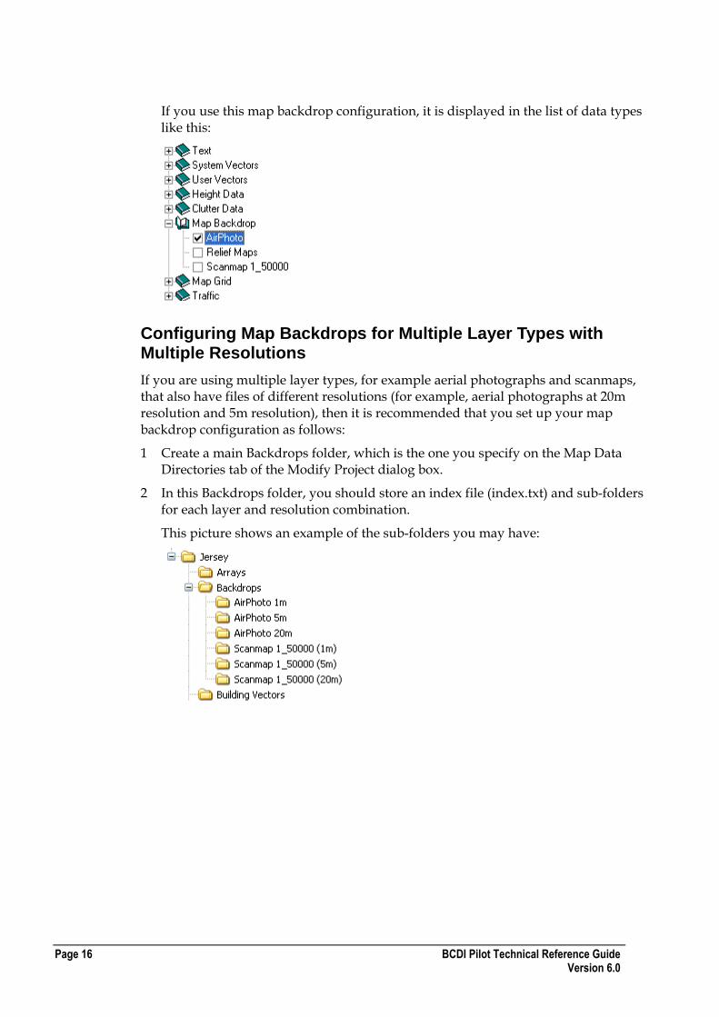
If you use this map backdrop configuration, it is displayed in the list of data types like this:
Configuring Map Backdrops for Multiple Layer Types
If you are using multiple layer types (for example aerial photographs and scanmaps) then it is recommended that you set up your map backdrop configuration as follows:
1 Create a main Backdrops folder, which is the one you specify on the Map Data Directories tab of the Modify Project dialog box.
2 In this Backdrops folder, you should store an index file (index.txt) and sub-folders for each layer.
This picture shows an example of the sub-folders you may have:
The top-level index file in the Backdrops folder should just reference all the sub-folders, for example:
Important : The order of the folders in this index file is the same as that in BCDI Pilot. In this configuration each of the layers would not normally be visible at the same time when displayed at 100% opacity. The folder names in the index file must exactly match those on the disk.
3 In each sub-folder, you should store an index file (index.txt) and all of the image files.
For more information on the index file, see About the File Format for Map Backdrops Index Files on page 18.
Page 16 BCDI Pilot Technical Reference Guide Version 6.0
If you use this map backdrop configuration, it is displayed in the list of data types like this:
Configuring Map Backdrops for Multiple Layer Types with Multiple Resolutions
If you are using multiple layer types, for example aerial photographs and scanmaps, that also have files of different resolutions (for example, aerial photographs at 20m resolution and 5m resolution), then it is recommended that you set up your map backdrop configuration as follows:
1 Create a main Backdrops folder, which is the one you specify on the Map Data Directories tab of the Modify Project dialog box.
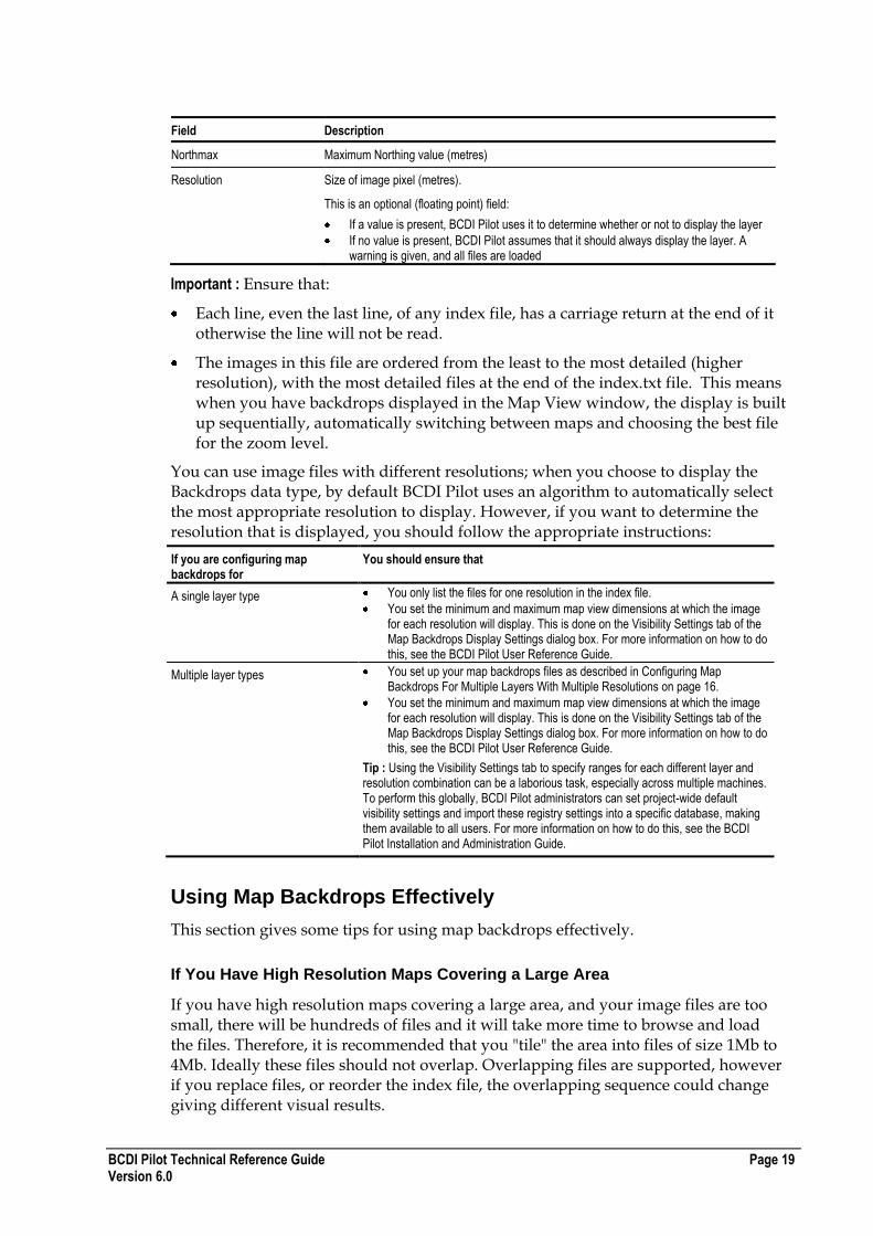
2 In this Backdrops folder, you should store an index file (index.txt) and sub-folders for each layer and resolution combination.
This picture shows an example of the sub-folders you may have:

BCDI Pilot Technical Reference Guide Page 17 Version 6.0
The top-level index file in the Backdrops folder should just reference all the sub-folders, for example:
Important : The order of the folders in this index file is the same as that in BCDI Pilot. If multiple folders represent the same layer type but at a different resolution, you should ensure that the highest resolution (lowest metres/pixel value) folders are at the bottom of the list for a particular layer type to ensure the higher resolution images are displayed over the coarser ones. In this advanced case, the layer types are not mutually exclusive as the visibility settings are used to control when certain resolutions are displayed. The folder names in the index file must exactly match those on the disk.
3 In each sub-folder, you should store an index file (index.txt) and all of the image files.
For more information on the index file, see About the File Format for Map Backdrops Index Files on page 18.
If you use this map backdrop configuration, it is displayed in the list of data types like this:

Page 18 BCDI Pilot Technical Reference Guide Version 6.0
About the File Format for Map Backdrops Index Files
There are 2 types of index file for map backdrops:
Top-level index files, stored in the main Backdrops folder
Image index files, stored in either the main Backdrops folder (for single layer types) or in any number of sub-folders (for multiple layer types)
Top-level Index Files
If you are setting up map backdrops for multiple layer types (with or without multiple resolutions), the top-level index file just references all of the sub-folders. For more information on this, see either Configuring Map Backdrops for Multiple Layer Types on page 15 or Configuring Map Backdrops for Multiple Layer Types with Multiple Resolutions on page 16.
If you are just setting up map backdrops for a single layer type, only one index file is needed and is the same format as the one described for the sub-folder index files.
Image Index Files
This index file can refer to multiple image files with one row giving information about one file.
This picture shows an example index.txt file:
Example Map Backdrops Index File
This table shows what is contained in the index.txt file:
Field Description
Filename Filename of data file
The combination of index filename and path should not exceed 255 characters, otherwise BCDI Pilot will truncate it. In the event of a duplication in the truncated names, BCDI Pilot will not add the duplicate.
Eastmin Minimum Easting value (metres)
Eastmax Maximum Easting value (metres)
Northmin Minimum Northing value (metres)
BCDI Pilot Technical Reference Guide Page 19 Version 6.0
Field Description
Northmax Maximum Northing value (metres)
Resolution Size of image pixel (metres).
This is an optional (floating point) field:
If a value is present, BCDI Pilot uses it to determine whether or not to display the layer
If no value is present, BCDI Pilot assumes that it should always display the layer. A warning is given, and all files are loaded
Important : Ensure that:
Each line, even the last line, of any index file, has a carriage return at the end of it otherwise the line will not be read.
The images in this file are ordered from the least to the most detailed (higher resolution), with the most detailed files at the end of the index.txt file. This means when you have backdrops displayed in the Map View window, the display is built up sequentially, automatically switching between maps and choosing the best file for the zoom level.
You can use image files with different resolutions; when you choose to display the Backdrops data type, by default BCDI Pilot uses an algorithm to automatically select the most appropriate resolution to display. However, if you want to determine the resolution that is displayed, you should follow the appropriate instructions:
If you are configuring map backdrops for
You should ensure that
A single layer type You only list the files for one resolution in the index file.
You set the minimum and maximum map view dimensions at which the image for each resolution will display. This is done on the Visibility Settings tab of the Map Backdrops Display Settings dialog box. For more information on how to do this, see the BCDI Pilot User Reference Guide.
Multiple layer types You set up your map backdrops files as described in Configuring Map Backdrops For Multiple Layers With Multiple Resolutions on page 16.
You set the minimum and maximum map view dimensions at which the image for each resolution will display. This is done on the Visibility Settings tab of the Map Backdrops Display Settings dialog box. For more information on how to do this, see the BCDI Pilot User Reference Guide.
Tip : Using the Visibility Settings tab to specify ranges for each different layer and resolution combination can be a laborious task, especially across multiple machines. To perform this globally, BCDI Pilot administrators can set project-wide default visibility settings and import these registry settings into a specific database, making them available to all users. For more information on how to do this, see the BCDI Pilot Installation and Administration Guide.
Using Map Backdrops Effectively
This section gives some tips for using map backdrops effectively.
If You Have High Resolution Maps Covering a Large Area
If you have high resolution maps covering a large area, and your image files are too small, there will be hundreds of files and it will take more time to browse and load the files. Therefore, it is recommended that you "tile" the area into files of size 1Mb to 4Mb. Ideally these files should not overlap. Overlapping files are supported, however if you replace files, or reorder the index file, the overlapping sequence could change giving different visual results.
Page 20 BCDI Pilot Technical Reference Guide Version 6.0
When the Map Backdrop Does Not Appear in the Map View Window
BCDI Pilot determines whether the map backdrop is worth displaying by checking that the image is not reduced too much.
The backdrop will not be displayed if it is compressed by more than a factor of three. When this happens, a frame indicating the map backdrop area is displayed on the map.
Further Advice on Using Map Backdrops Effectively
The following factors have an impact on the proper use of map backdrops:
The estimated number of metres per pixel is calculated based on the file size and on the assumption that the image is square. Consequently, if your images are very long and thin or short and wide, the visibility algorithm will give differing results for the same metres/pixel images. If you want to use the automatic resolution selection algorithm it is recommended that the images are square rather than rectangular. Alternatively, you could explicitly specify the resolution directly in the index file and/or use the backdrop visibility settings.
Always use the file naming conventions suggested in the Installation and Administration Guide. In particular:
Use relative path names within the image filename to allow a structured approach to map data directory organisation.
Arrange the images into directories corresponding to the metres / pixel value – to make life easier when working with multiple resolutions and improve folder browsing speed when many images are present in a folder.
Vector Data
Line/Vector data contains features such as roads, railways, coastlines, and so on. Separate mapping features must be in separate data files, however there can be more than one file for a specific vector.
Building vector data is a specialised version of normal vector data, which contains a particular attribute called 'building' and describes the shapes and heights of buildings in more detail. The application of such data will typically be to provide input for ray-tracing type propagation models, used for the generation microcell coverage within the planning tool.
All vector data now uses a MapInfo *.tab file format.
BCDI Pilot uses a structured index file (index.xml) to organise a collection of vectors and their constituent *.tab files, and register them with the system.
You can create an index.xml file in a number of ways:
If you have TAB vector files, use the Vector Manager to register the new vectors with BCDI Pilot as it will automatically create/update the index.xml for you. This is by far the most straightforward way. For more information, see the ENTERPRISE User Reference Guide.

BCDI Pilot Technical Reference Guide Page 21 Version 6.0
If you have TAB vector files but do not want to use the Vector Manager, see the topics and examples in this section for information on how to create an index.xml manually, or use the the GenerateIndexXml power tool to automatically generate an index.xml for a folder hierarchy full of TAB files.
If you have old format vector files (an index.txt file and *.txt vector files), you can create an index.xml file and convert the vectors to TAB format using the Index2Tab power tool, which is available from Product Support.
For more information on the format of the index.xml file, see About the Vector Index.xml File Format on page 21.
About the Vector Index.xml File Format
The vector index.xml file format has the following characteristics:
Each file must start with:
<?xml version="1.0" encoding="utf-8"?>
<VECTOR-LAYER-LIST VERSION="1.0">
And end with:
</VECTOR-LAYER-LIST>
You can have 0 or more layers, but each VECTOR must have a TAB-FILE-LIST section.
Each LAYER, VECTOR and TAB-FILE must have a GUID attribute, which uniquely identifies each entity. A GUID is a unique 128-bit number formatted in the following hexadecimal arrangement "00000000-0000-0000-0000-000000000000". If you are creating a new index.xml file, you do not need to specify a value, because BCDI Pilot automatically adds any missing values. If you want to create GUIDs yourself, please see http://tinyurl.com/ygmq9u.
Important :
You cannot have duplicate GUID values within each index.xml file
Do not modify GUID values after they have been generated
Each LAYER consists of the following attributes:
A NAME attribute, which stores the name of the layer as defined in the Vector Manager
A GUID attribute (see above)
Any number of VECTOR sections
Each VECTOR consists of the following attributes:
A NAME attribute, which stores the name of the vector as defined in the Vector Manager
A GUID attribute (see above)
A TAB-FILE-LIST section, which must contain 1 or more TAB-FILE sections.
For large vectors, you may have multiple TAB-FILE sections in the same TAB-FILE-LIST. For more information, click here.

Page 22 BCDI Pilot Technical Reference Guide Version 6.0
Each TAB-FILE contains the following compulsory attributes:
A FILENAME attribute, which identifies the vector *.tab file containing the vector data. This must include the .tab extension, and is relative to the PATH attribute
A GUID attribute (see above)
Path of the filename relative to the index.xml location, or alternatively a fully qualified path.
A PATH attribute, which is usually the path of the vector filename relative to the index.xml location, but can be a fully-qualified path.
An ATTRIB-NAME-IDX attribute, which Planner uses to join *.tab file attribute names together to form a unique name. Leave this blank, or specify a comma-separated list of attribute column numbers starting with 1. For example, to include the first column only, type '1' or to include the first three columns, type '1,2,3'. When BCDI Pilot generates per polygon statistics this compound naming column is used.
Tab files for building vectors have their own special conditions. For more information, see About TAB Files for Building Vectors on page 22.
This picture shows a graphical representation of the XML schema:
Vector XML Schema
You can obtain this XML schema as an *.xsd file from Product Support.
About TAB Files for Building Vectors
The TAB files for building vectors have their own special conditions:
The TAB-FILE must contain a BUILDING attribute, which stores the height above DTM as a float
If you are using highly-detailed building data, a single building which has data at various heights will be divided into a number of features, with each one representing a discrete part of the overall building structure.
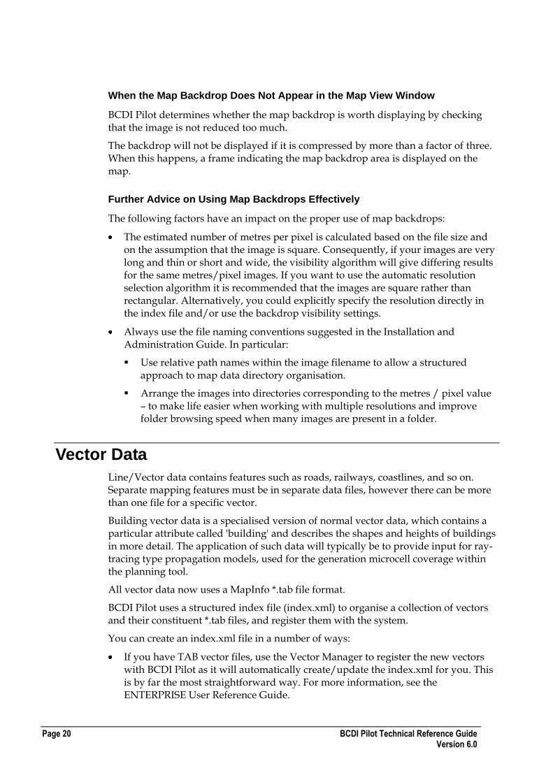
BCDI Pilot Technical Reference Guide Page 23 Version 6.0
For example, consider this tower block:
Viewed from above, it can be separated into 3 'strata' of height, each represented here by a different colour:

Page 24 BCDI Pilot Technical Reference Guide Version 6.0
Each of these strata will appear as a separate feature within the overall building feature, each with its own BUILDING value:
When the building vectors have been imported, if you hover the cursor over a particular point on the building, the height shown will be the height for that particular vector feature.
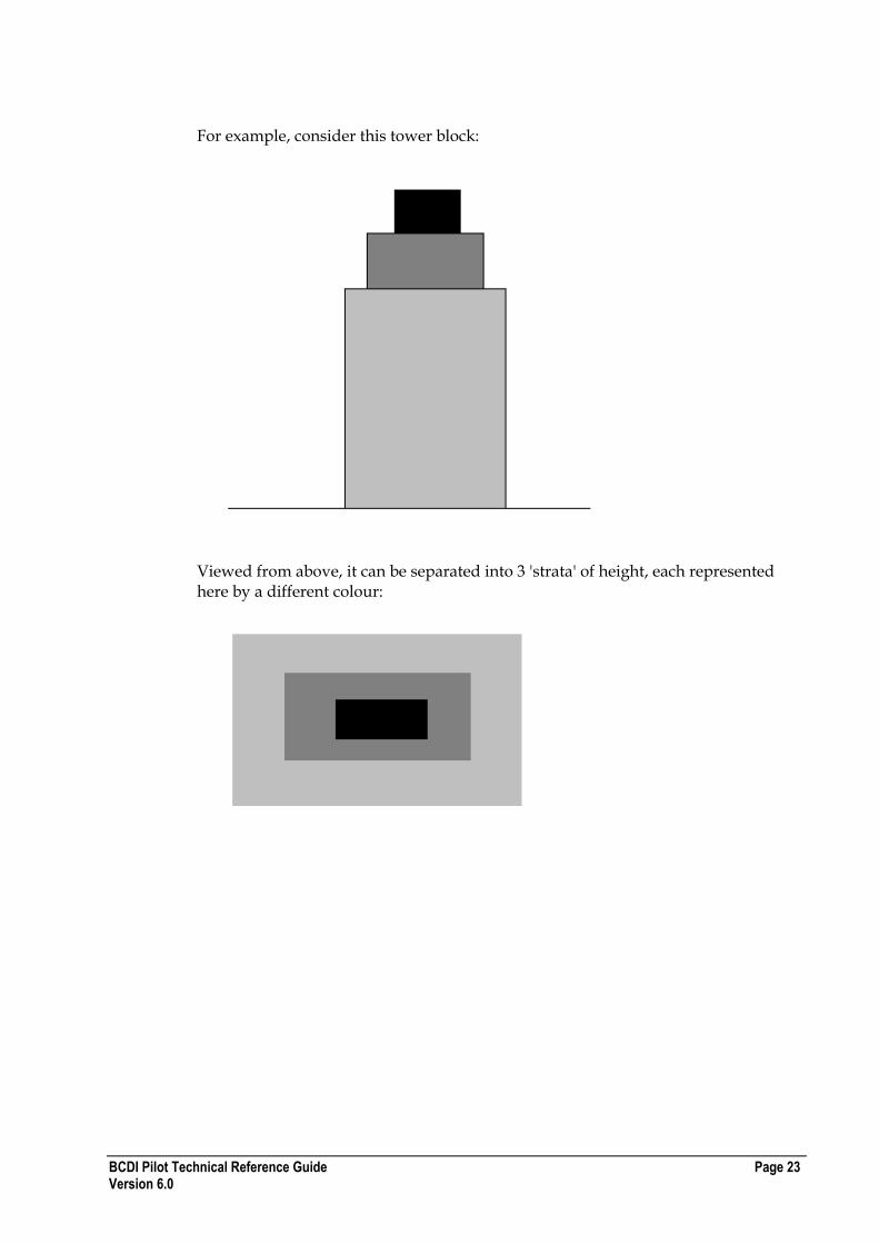
Using Multiple TAB-FILE Entries in the Same TAB-FILE-LIST
If you have large vectors, you can have multiple TAB-FILE entries in the same TAB-FILE-LIST. In this way, large areas of map data can be 'tiled' into separate sections, then brought together under one VECTOR.
BCDI Pilot Technical Reference Guide Page 25 Version 6.0
For example, the map data for this location could be split into four sections, each with its own tab file:
The tab files could be NW.tab, NE.tab, SW.tab and SE.tab, corresponding with the areas of data they cover.
In the index.xml file, they would appear as: <?xml version="1.0" encoding="utf-8"?>
<VECTOR-LAYER-LIST VERSION="1.0">
<VECTOR NAME="Large_Region" GUID="0A4E2A65-5F99-4662-8DBF-43975FC2CA40">
<TAB-FILE-LIST>
<TAB-FILE FILENAME="NW.tab" GUID="8EB8882E-83C8-4C57-95F4-EB5FFE6B5BF2" PATH="" ATTRIB-NAME-IDX="" />
<TAB-FILE FILENAME="NE.tab" GUID="FDD4D6EB-7779-43BF-977F-142CFE9F9CA4" PATH="" ATTRIB-NAME-IDX="" />
<TAB-FILE FILENAME="SW.tab" GUID="C066E1CA-149B-436D-8380-89E6212B950A" PATH="" ATTRIB-NAME-IDX="" />
<TAB-FILE FILENAME="SE.tab" GUID="38A23C47-B413-492D-AEFA-75ADCF9E0D68" PATH="" ATTRIB-NAME-IDX="" />
</TAB-FILE-LIST>
</VECTOR>
</VECTOR-LAYER-LIST>

Page 26 BCDI Pilot Technical Reference Guide Version 6.0
You could also use these separate tab files again in four individual vectors, for example NW_Region, NE_Region, SW_Region and SE_Region. If this were the case, they each would be given a new, different GUID. This would be particularly useful if you were mapping a number of large cities in a single region, and wanted to treat the cities as a group and also as separate entities.
Example Vector Index.xml File
This topic describes an example vector index.xml file, which is based on the following structure in the Vector Manager:
Vector Manager structure
Here is the corresponding index.xml: <?xml version="1.0" encoding="utf-8" ?>
<VECTOR-LAYER-LIST VERSION="1">
<LAYER NAME="Geographic Features" GUID="1689c128-dea1-4072-8644-8ca5db9421fa">
</LAYER>
<LAYER NAME="Transportation Routes" GUID="D25EE297-ABC5-4DCE-B3AE-637C3391C98E">
<VECTOR NAME="A-road" GUID="0A4E2A65-5F99-4662-8DBF-43975FC2CA40">
<TAB-FILE-LIST>
<TAB-FILE FILENAME="A-road_hp_bin.tab" GUID="8EB8882E-83C8-4C57-95F4-EB5FFE6B5BF2" PATH="" ATTRIB-NAME-IDX="" />
<TAB-FILE FILENAME="A-road_hu_bin.tab" GUID="FDD4D6EB-7779-43BF-977F-142CFE9F9CA4" PATH="" ATTRIB-NAME-IDX="" />

BCDI Pilot Technical Reference Guide Page 27 Version 6.0
<TAB-FILE FILENAME="A-road_hy_bin.tab" GUID="C066E1CA-149B-436D-8380-89E6212B950A" PATH="" ATTRIB-NAME-IDX="" />
<TAB-FILE FILENAME="NI-ACLASS_bin.tab" GUID="63C49B18-5F82-4068-B4A0-39F634167D50" PATH="" ATTRIB-NAME-IDX="" />
<TAB-FILE FILENAME="NI-NAT_SEC_bin.tab" GUID="559CFB5D-00B1-49D6-9A22-57281FF38841" PATH="" ATTRIB-NAME-IDX="" />
<TAB-FILE FILENAME="NI-REGIONAL_bin.tab" GUID="F91061EE-F375-4CBF-AA27-93929E811C70" PATH="" ATTRIB-NAME-IDX="" />
</TAB-FILE-LIST>
</VECTOR>
<VECTOR NAME="B-road" GUID="626DC2F0-B2E7-4B49-843B-0F519BB369BD">
<TAB-FILE-LIST>
<TAB-FILE FILENAME="B-road_hp_bin.tab" GUID="503C80C8-B56F-4807-BB6A-BCAAB3279334" PATH="" ATTRIB-NAME-IDX="" />
<TAB-FILE FILENAME="B-road_hu_bin.tab" GUID="09D6DC5A-94F8-4334-BF08-3321DE0A9BD5" PATH="" ATTRIB-NAME-IDX="" />
<TAB-FILE FILENAME="B-road_hy_bin.tab" GUID="AF2CB126-20D3-4B57-8675-63CB0143EEA4" PATH="" ATTRIB-NAME-IDX="" />
<TAB-FILE FILENAME="NI-BCLASS_bin.tab" GUID="6750068E-5AD7-4937-8956-F254067DCB8C" PATH="" ATTRIB-NAME-IDX="" />
</TAB-FILE-LIST>
</VECTOR>
</LAYER>
</VECTOR-LAYER-LIST>
Building Raster Data
The DEM format is exactly the same as the DTM except that the height values stored represent building height above ground level, that is, flat earth. Typically the pixel sizes would be in the range of 1m to 10m.
Text Data
Text data consists of features such as town names, city names, and so on. The text data is stored in either ASCII files or in a proprietary binary format. Separate mapping features must be in separate data files, however there can be more than one file for a single feature.
Index File
An ASCII text file called index.txt contains positional information about text. Relative path names can be incorporated within the filename to allow a structured approach to map data directory organisation.
Each row contains the following variables separated by a space:
Field Description
Filename Filename of text data file
The combination of index filename and path should not exceed 255 characters otherwise BCDI Pilot will truncate it and in the event of a duplication in the truncated names, BCDI Pilot will not add the duplicate.
Eastmin Minimum Easting value (metres)
Eastmax Maximum Easting value (metres)
Northmin Minimum Northing value (metres)
Northmax Maximum Northing value (metres)
Page 28 BCDI Pilot Technical Reference Guide Version 6.0
Field Description
Feature Name Textual Description of the text data file.
For example:
The final row is terminated by a carriage return.
ASCII Text Format
Each row contains the following variables separated by a space:
Field Description
Easting Easting position of the text (metres)
Northing Northing position of the text (metres)
Text Text to be displayed
For example:
The final row is terminated by a carriage return.
Binary Text Format
Binary format files must have the file extension .bin and can only be created from the text format files using the text2bin.exe program which can be found in the BCDI Pilot program directory. Converting to binary text improves application performance and reduces disk usage requirements.
The format of the binary files is a continuous set of records, one for each entry. Each record contains x and y co-ordinates as 32-bit signed integers followed by a 24 character array containing the text to be displayed. The character string should be NULL terminated.

BCDI Pilot Technical Reference Guide Page 29 Version 6.0
BCDI Pilot File Formats
Many file formats are supported within the BCDI Pilot suite, some of them are unique to BCDI Pilot whereas others are common to a variety of tools. This section describes all the file formats that you can use in one or more BCDI Pilot tools.
Important : Except where otherwise mentioned, spaces in text files are treated as delimiters. Therefore, if you have spaces within names of models, antennas, carrier layers and so on, you need to remove them. It is recommended that you replace them with underscores or run the words together, for example, Flat Terrain becomes FlatTerrain. This may mean temporarily changing your existing BCDI Pilot names so that items will match those from the import file. After a successful import, you can change the names back again.
Warning : If an export is made from a database that uses spaces, it will not be possible to import without editing the file manually.
In This Section
Import and Export File Formats 30 Coverage and Interference Arrays 40 Simulation Array File Formats 44 Interference Tables 47 Neighbours 49 Predictions 49 Traffic Raster 50 Carrier Wave (CW) Measurements 52 View Favourites 57 User-Defined Fields 58 Colour Palette File Format 60 File Formats Used in ILSA 60 Live Traffic File Formats for 2g Networks 64 Live Traffic File Formats for 3g Networks 65 Live Traffic File Formats for WiMAX Networks 65
A P P E N D I X B
Page 30 BCDI Pilot Technical Reference Guide Version 6.0
Import and Export File Formats
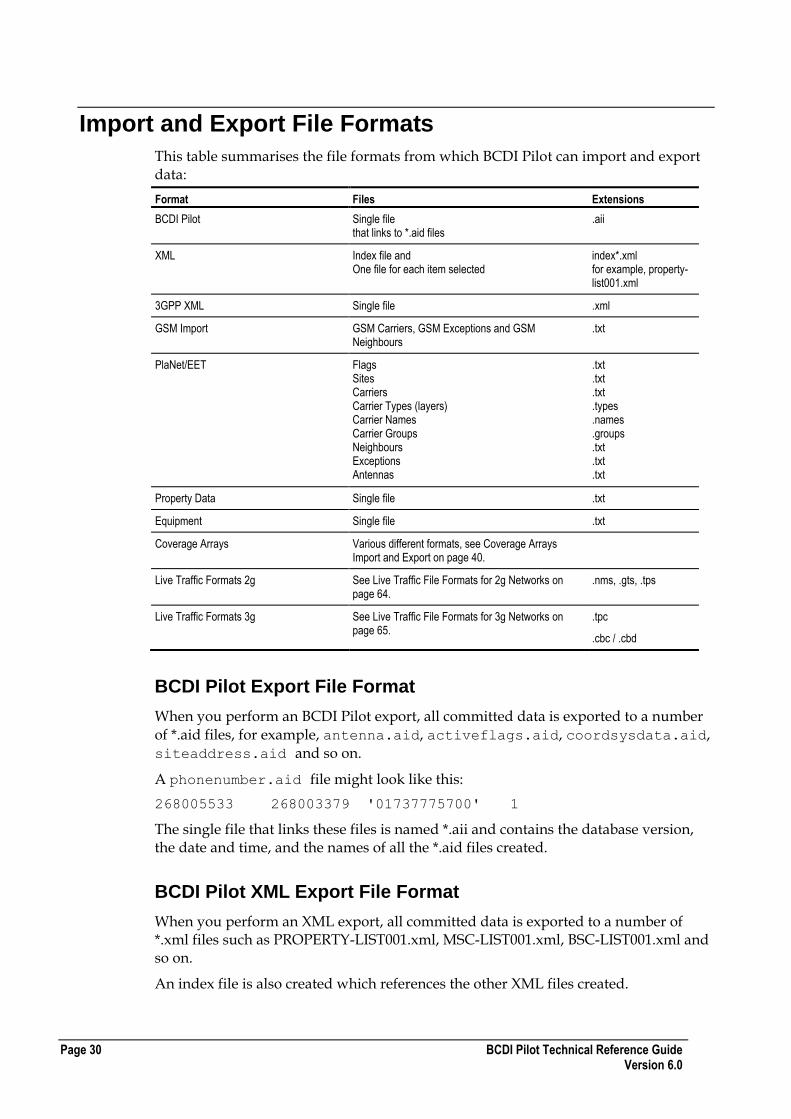
This table summarises the file formats from which BCDI Pilot can import and export data:
Format Files Extensions
BCDI Pilot Single file that links to *.aid files
.aii
XML Index file and One file for each item selected
index*.xml for example, property-list001.xml
3GPP XML Single file .xml
GSM Import GSM Carriers, GSM Exceptions and GSM Neighbours
.txt
PlaNet/EET Flags Sites Carriers Carrier Types (layers) Carrier Names Carrier Groups Neighbours Exceptions Antennas
.txt
.txt
.txt
.types
.names
.groups
.txt
.txt
.txt
Property Data Single file .txt
Equipment Single file .txt
Coverage Arrays Various different formats, see Coverage Arrays Import and Export on page 40.
Live Traffic Formats 2g See Live Traffic File Formats for 2g Networks on page 64.
.nms, .gts, .tps
Live Traffic Formats 3g See Live Traffic File Formats for 3g Networks on page 65.
.tpc
.cbc / .cbd
BCDI Pilot Export File Format
When you perform an BCDI Pilot export, all committed data is exported to a number
of *.aid files, for example, antenna.aid, activeflags.aid, coordsysdata.aid,
siteaddress.aid and so on.
A phonenumber.aid file might look like this:
268005533 268003379 '01737775700' 1
The single file that links these files is named *.aii and contains the database version, the date and time, and the names of all the *.aid files created.
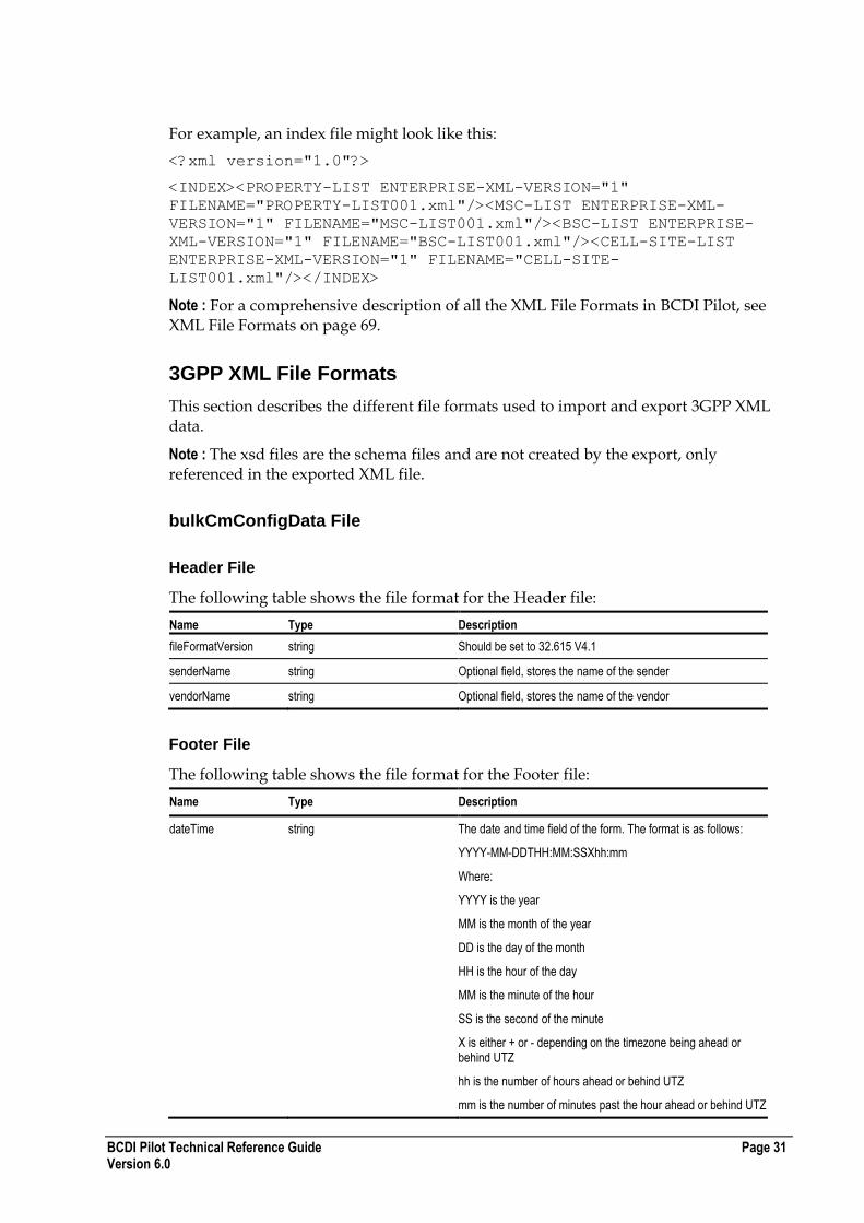
BCDI Pilot XML Export File Format
When you perform an XML export, all committed data is exported to a number of *.xml files such as PROPERTY-LIST001.xml, MSC-LIST001.xml, BSC-LIST001.xml and so on.
An index file is also created which references the other XML files created.
BCDI Pilot Technical Reference Guide Page 31 Version 6.0
For example, an index file might look like this:
<?xml version="1.0"?>
<INDEX><PROPERTY-LIST ENTERPRISE-XML-VERSION="1"
FILENAME="PROPERTY-LIST001.xml"/><MSC-LIST ENTERPRISE-XML-
VERSION="1" FILENAME="MSC-LIST001.xml"/><BSC-LIST ENTERPRISE-
XML-VERSION="1" FILENAME="BSC-LIST001.xml"/><CELL-SITE-LIST
ENTERPRISE-XML-VERSION="1" FILENAME="CELL-SITE-
LIST001.xml"/></INDEX>
Note : For a comprehensive description of all the XML File Formats in BCDI Pilot, see XML File Formats on page 69.
3GPP XML File Formats
This section describes the different file formats used to import and export 3GPP XML data.
Note : The xsd files are the schema files and are not created by the export, only referenced in the exported XML file.
bulkCmConfigData File
Header File
The following table shows the file format for the Header file:
Name Type Description
fileFormatVersion string Should be set to 32.615 V4.1
senderName string Optional field, stores the name of the sender
vendorName string Optional field, stores the name of the vendor
Footer File
The following table shows the file format for the Footer file:
Name Type Description
dateTime string The date and time field of the form. The format is as follows:
YYYY-MM-DDTHH:MM:SSXhh:mm
Where:
YYYY is the year
MM is the month of the year
DD is the day of the month
HH is the hour of the day
MM is the minute of the hour
SS is the second of the minute
X is either + or - depending on the timezone being ahead or behind UTZ
hh is the number of hours ahead or behind UTZ
mm is the number of minutes past the hour ahead or behind UTZ
Page 32 BCDI Pilot Technical Reference Guide Version 6.0
configData File
This table shows the file format for the configData file:
Name Type Description
dnPrefix string Export Prefix in the RANOS XML Export dialog box
xn:SubNetwork id string Sub-Network ID on the General tab of a Logical Network selected in the Site Database
xn:MeContext id string MeContext ID on the General tab of a Logical Network selected in the Site Database
xn:ManagedElementid string Managed Element ID on the General tab of an RNC node selected in the Site Database
xn:managedElementType string The type of element (in this case, this should always be RNC)
Note : xn:SubNetwork id, xn:MeContext and xn:ManagedElement can be followed by id, and a string as per the table above and/or by a modifier (create, delete or update). The modifier applies to all of the elements parented by the XML element. Elements with create and delete modifiers are ignored for all XML elements except for UtranRelation and GsmRelation.
un:RncFunction File
This table shows the file format for the un:RncFunction file:
Name Type Description
rncFunctionId string RNC Function ID on the General tab of an RNC node selected in the Site Database
userLabel string RNC Identity on the General tab of an RNC node selected in the Site Database
Mcc number Mobile Country Code on the General tab of the associated PLMN node selected in the Site Database
Mnc number Mobile Network Code on the General tab of the associated PLMN node selected in the Site Database
rncId number UMTS RNC Identity on the General tab of an RNC node selected in the Site Database
un:UtranCell File
This table shows the file format for the un:UtranCell file:
Name Type Description
utranCellId number RDN field, concatenated from the cell ID and the rncId
userLabel string The Cell Identity on the General tab of a Cell selected in the Site Database.
cId number The UMTS Cell ID on the General tab of a Cell selected in the Site Database.
localCellId number The Cell ID on the General tab of a Cell selected in the Site Database.
uarfcnUl number The UL UTRA Absolute Radio Frequency Number. This is the UL Channel Number of the carrier assigned to the Cell.
You define the uplink channel number in the 3g Carriers dialog box. The Cell Params tab for the cell shows assigned carriers.

BCDI Pilot Technical Reference Guide Page 33 Version 6.0
uarfcnDl number The DL UTRA Absolute Radio Frequency Number. This is the DL Channel Number of the carrier assigned to the Cell.
You define the downlink channel number in the 3g Carriers dialog box. The Cell Params tab for the cell shows assigned carriers.
primaryScramblingCode number The primary DL scrambling code used by the cell. This is defined in the Scrambling Code field on the Cell Params tab of the Cell in the Site Database.
primaryCpichPower number The power of the primary CPICH channel in the cell (the units correspond to 0.1dBm). This is defined in the Pilot Power field on the Cell Params tab for a Cell in the Site Database.
maximumTransmissionPower number The maximum transmission power of a cell, DL Power (units correspond to 0.1dBm). This is defined in the Max Tx Power field on the Cell Params tab for a Cell in the Site Database.
primarySchPower number The Primary Sync Channel Power (units correspond to 0.1dBm). This is defined in the Primary Synch Channel Power field on the Cell Params tab for a Cell in the Site Database.
secondarySchPower number The Secondary Sync Channel Power (units correspond to 0.1dBm). This is defined in the Secondary Synch Channel Power field on the Cell Params tab for a Cell in the Site Database.
bchPower number The power of the broadcast channel in the cell and is equivalent to the new Primary Common Control Channel Power field. This is defined on the Cell Params tab for a Cell in the Site Database.
Lac number The Location Area Code, defined on the General tab of the Cell in the Site Database.
Rac number The Routing Area Code, defined on the General tab for a Cell in the Site Database.
Sac number The Service Area Code, defined on the General tab for a Cell in the Site Database.
un:UtranRelation File
The following table shows the format for the un:UtranRelation file:
Name Type Description
utranRelationId number A reference index into the list of UTRAN neighbours. This is automatically generated by BCDI Pilot. This is not used for anything else.
relationType string Defines the neighbour cell relations between UTRAN cells (intrasystem) and between UTRAN cells and GSM cells (intersystem). As well as being intrasystem or intersystem, neighbour cell relations can be intrafrequency or interfrequency, depending on the carrier of the neighbouring cell.
adjacentCell string The Distinguished Name (DN) of the Neighbouring UTRAN cell.
uarfcnUI number The UL UTRA Absolute Radio Frequency Number. This is determined by looking up the UL Channel Number of the carrier that has been assigned on the Cell Params tab of the UMTS Cell in the Site Database. The UL Channel Number is defined in the 3g Carriers dialog box.
Note : Used for EXPORT only

Page 34 BCDI Pilot Technical Reference Guide Version 6.0
uarfcnDI number The DL UTRA Absolute Radio Frequency Number. This is determined by looking up the DL Channel Number of the carrier that has been assigned on the Cell Params tab of UMTS Cell in the Site Database. The DL Channel Number is defined in the 3g Carriers dialog box.
Note : Used for EXPORT only
primaryScramblingCode number The primary DL scrambling code used by the cell. This is defined in the Scrambling Code field on the Cell Params tab of the UMTS Cell in the Site Database.
Note : Used for EXPORT only
primaryCpichPower number The power of the primary CPICH channel in the cell (the units correspond to 0.1dBm). This is defined in the Pilot Power field on the Cell Params tab of the UMTS Cell in the Site Database.
Note : Used for EXPORT only
Lac number The Location Area Code, defined on the General tab of the UMTS Cell in the Site Database.
Note : Used for EXPORT only
Note : UtranRelations can only be specified with create or delete modifiers. This means that when you import, unwanted neighbour relations will first be deleted and then the new relations will be created.
gn:GsmRelation File
The following table shows the format for the gn:GsmRelation file:
Name Type Description
gsmRelationId number A reference index into the list of GSM neighbours. This is automatically generated by BCDI Pilot. This is not used for anything else.
relationType string This is set as intersystem:interfrequency.
adjacentCell string The DN of the neighbouring GSM cell in the XML schema. This is derived from the sub-network ID and the External GSM Cell identity (RDN).
bcchFrequency number This contains the absolute radio frequency channel number of the BCCH channel of the neighbouring GSM cell. It is determined by finding the selected frequency in the control carrier layer of the GSM Cell.
Note : Used for EXPORT only
ncc number The Network Colour Code, defined on the General tab of the neighbouring GSM Cell in the Site Database.
Note : Used for EXPORT only
bcc number The Base Station Colour Code, defined on the General tab of the neighbouring GSM Cell in the Site Database.
Note : Used for EXPORT only
Lac number The Location Area Code. This is derived from the ID of the LAC object associated with the GSM neighbour Cell, defined on the General tab of the cell in the Site Database.
Note : Used for EXPORT only

BCDI Pilot Technical Reference Guide Page 35 Version 6.0
Note : GsmRelations can only be specified with create or delete modifiers. This means that when you import, unwanted neighbour relations will be deleted first and then the new relations will be created.
ExternalUtranCell File
This file informs RANOS of the existence of a cell that is assigned to a different logical network (sub-network) to that being imported or exported.
This data structure should be exported whenever a neighbour relation in a different logical network is exported. However, it should be ignored on import.
The following table shows the format for ExternalUtranCell file:
Name Type Description
externalUtranCellId number This RDN field is derived by concatenating the sub-Network ID, the managedElement ID, the rncID, and the cell Cid of the neighbour cell.
userLabel string The Cell ID of the neighbour cell, defined on the General tab of the neighbouring GSM Cell in the Site Database.
cId number The UMTS Cell ID of the neighbour cell, defined on the General tab of the neighbouring GSM Cell in the Site Database.
mcc number The Mobile Country Code of the PLMN associated with the neighbour cell's RNC. It is defined on the General tab of the PLMN in the Site Database.
mnc number The Mobile Network Code of the PLMN associated with the neighbour cell's RNC. It is defined on the General tab of the PLMN in the Site Database.
rncId number The RNC Id of the neighbour cell's RNC, defined on the General tab of the RNC in the Site Database.
uarfcnUl number The UL UTRA Absolute Radio Frequency Number. This is determined by looking up the UL Channel Number of the carrier that has been assigned on the Cell Params tab of the Cell in the Site Database. The UL Channel Number is defined in the 3g Carriers dialog box.
uarfcnDl number The DL UTRA Absolute Radio Frequency Number. This is determined by looking up the DL Channel Number of the carrier that has been assigned on the Cell Params tab of a Cell in the Site Database. The DL Channel Number is defined in the 3g Carriers dialog box.
primaryScramblingCode number The primary DL scrambling code used by the cell. This is defined in the Scrambling Code field on the Cell Params tab of the Cell in the Site Database.
primaryCpichPower number The power of the primary CPICH channel in the cell (the units correspond to 0.1dBm). This is defined in the Pilot Power field on the Cell Params tab of the Cell in the Site Database.
Lac number The Location Area Code, defined on the General tab of the Cell in the Site Database.
Rac number The Routing Area Code, defined on the General tab of the Cell in the Site Database.
ExternalGsmCell File
This data structure is used to inform the RANOS of the existence of an external GSM/EDGE cell, in other words, a GSM cell configured by another device. BCDI Pilot assumes that all GSM devices are configured by a different device to RANOS (for example, TMOS) and so all GSM cells are defined as external.
This data structure should be exported whenever a GSM neighbour relation is exported. However, it should be ignored on import.
Page 36 BCDI Pilot Technical Reference Guide Version 6.0
The following table shows the format for ExternalGsmCell file:
Name Type Description
externalGsmCellId number The external GSM cell identity (RDN) is derived by concatenating the GSM MCC, MNC, LAC and GSM ID numbers, taken from the General tab of the GSM Cell in the Site Database.
userLabel string The Cell ID, taken from the General tab of the GSM Cell in the Site Database.
cellIdentity number The GSM ID, taken from the General tab of the GSM Cell in the Site Database.
bcchFrequency number This contains the absolute radio frequency channel number of the BCCH channel of the neighbouring GSM cell. It is determined by finding the selected frequency in the control carrier layer of the GSM Cell.
ncc number The Network Colour Code, defined on the General tab of the neighbouring GSM Cell in the Site Database.
bcc number The Base Station Colour Code, defined on the General tab of the neighbouring GSM Cell in the Site Database.
Lac number The Location Area Code, defined on the General tab of the Cell in the Site Database.
GSM Import
Using the GSM Import from the File menu, you can import:
GSM Carriers
GSM Exceptions
GSM Neighbours
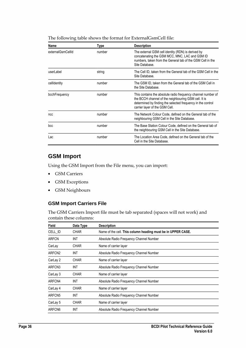
GSM Import Carriers File
The GSM Carriers Import file must be tab separated (spaces will not work) and contain these columns:
Field Data Type Description
CELL_ID CHAR Name of the cell. This column heading must be in UPPER CASE.
ARFCN INT Absolute Radio Frequency Channel Number
CarLay CHAR Name of carrier layer
ARFCN2 INT Absolute Radio Frequency Channel Number
CarLay 2 CHAR Name of carrier layer
ARFCN3 INT Absolute Radio Frequency Channel Number
CarLay 3 CHAR Name of carrier layer
ARFCN4 INT Absolute Radio Frequency Channel Number
CarLay 4 CHAR Name of carrier layer
ARFCN5 INT Absolute Radio Frequency Channel Number
CarLay 5 CHAR Name of carrier layer
ARFCN6 INT Absolute Radio Frequency Channel Number

BCDI Pilot Technical Reference Guide Page 37 Version 6.0
CarLay 6 CHAR Name of carrier layer
Cell Layer Name CHAR Name of cell layer
BCC INT Base Station Colour Code
TRX Req INT Number of transceivers required for the carrier layer.
-1 is used to automatically set the transceivers required to the actual number of carriers allocated in the file.
HSN INT Hopping sequence number
Hopping Type CHAR Choice of these hopping types:
None
Baseband
Synthesized
Note : These are case sensitive.
NCC INT Network Colour Code, must be in the range 0 - 7
For each subsequent row, after the header row, include the appropriate data.
If you only want to import less than 6 carriers, leave the remaining column pairs empty but retain the tabs. For example, if importing 4 carriers, leave ARFCN5 and CarLay5 and ARFCN6 and CarLay6 empty.
If you need to import more than 6 carriers, start a new row with the same Cell ID and it will add them accumulatively.
Carriers are imported to the carrier layers defined on each row. You can only specify one cell layer per row, so if you want to import to multiple cell layers include multiple rows for the same cell identifier.
Warning : If a cell is referred to in the GSM carriers file, when you import, any existing carrier layer and carrier allocations for that cell are replaced with the information given in the file. Therefore, you cannot use this file to merge.
An example of part of a GSM Carriers File is shown below:
Page 38 BCDI Pilot Technical Reference Guide Version 6.0
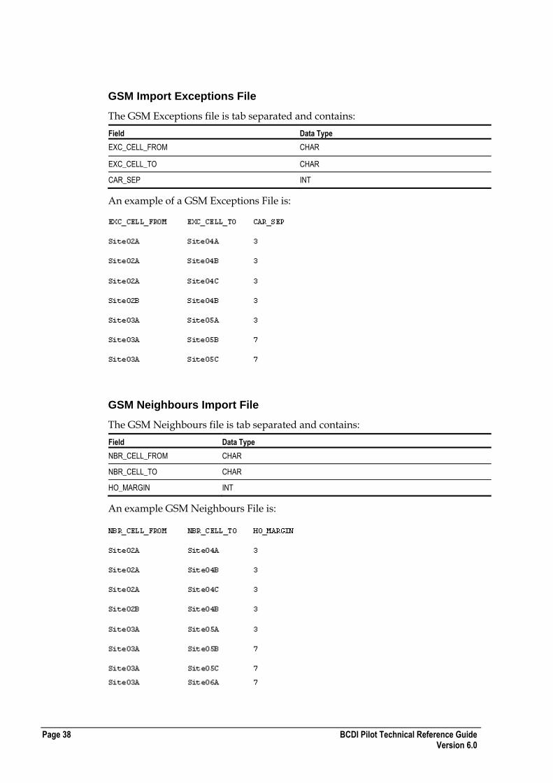
GSM Import Exceptions File
The GSM Exceptions file is tab separated and contains:
Field Data Type
EXC_CELL_FROM CHAR
EXC_CELL_TO CHAR
CAR_SEP INT
An example of a GSM Exceptions File is:
GSM Neighbours Import File
The GSM Neighbours file is tab separated and contains:
Field Data Type
NBR_CELL_FROM CHAR
NBR_CELL_TO CHAR
HO_MARGIN INT
An example GSM Neighbours File is:

BCDI Pilot Technical Reference Guide Page 39 Version 6.0
Properties Export and Import File Format
You can export and import Properties in BCDI Pilot. The file format for Properties is as follows.
One header row lists the fields that are exported for each Property, that is:
PROPERTY ID
ADDR1
ADDR2
TOWN
PROVINCE
POSTCODE
X and Y or LON and LAT
GNDHT
CONTACTFIRST
CONTACTLAST
MTTR
Following the header row, there is one line per Property containing these fields separated by tabs.
An example of an exported Properties file containing Easting & Northing co-ordinates is shown here:
Equipment Export and Import File Format
When you export equipment in BCDI Pilot, the information for the selected equipment is exported into a single text file. This file is tab-separated so you can easily edit it in Microsoft Excel and contains these sections:
A description of the equipment.
Header fields that describe each of the columns inside the text file.
The equipment data itself. This comprises all the fields from the database tables except for the Created and Last Modified fields.
Refer to the Database Reference Guide for descriptions of each field, for example in the Microwave Antenna section of the file, the field Polarisation Gain specifies the polarisation associated with the antenna, that is, horizontal (0), vertical (1) or cross polar (2) and is the field polarisation from the table MWANTENNATYPE.
Warning : Do not edit the long number strings contained in the file. These tell the software exactly what version of the equipment it is importing. For more tips on modifying the file, see Modifying the All Equipment File for Re-Import of Data.
Page 40 BCDI Pilot Technical Reference Guide Version 6.0
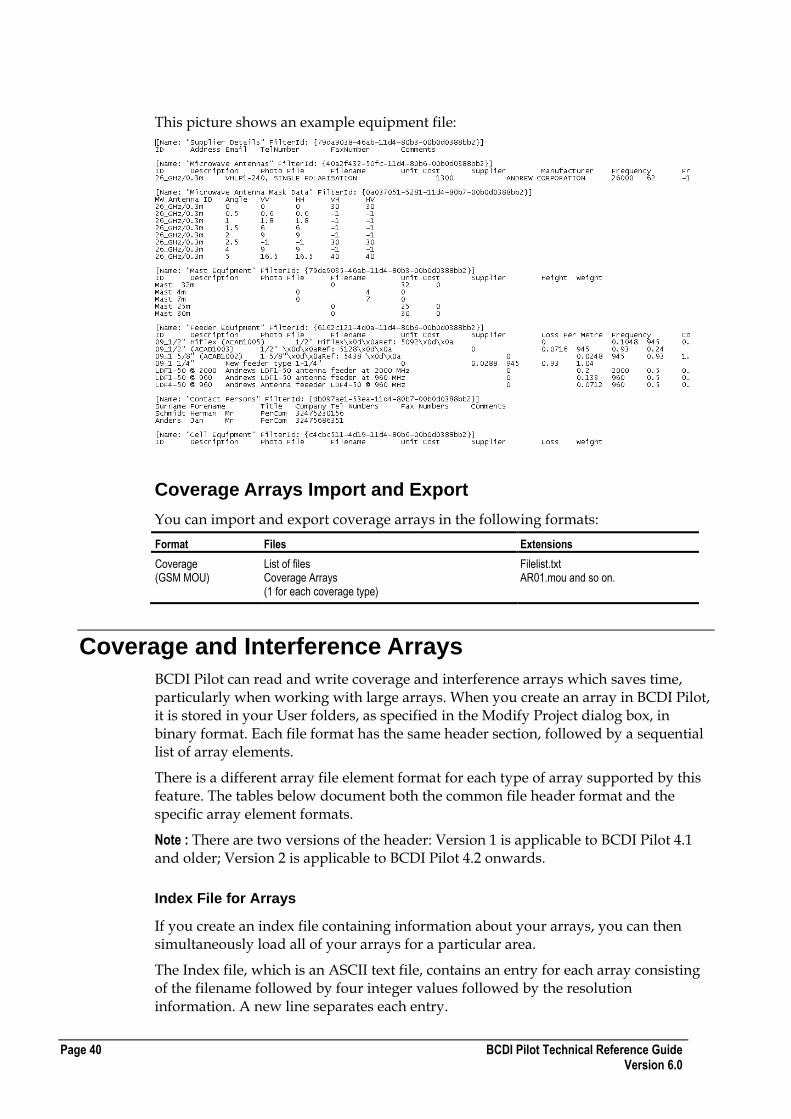
This picture shows an example equipment file:
Coverage Arrays Import and Export
You can import and export coverage arrays in the following formats:
Format Files Extensions
Coverage (GSM MOU)
List of files Coverage Arrays (1 for each coverage type)
Filelist.txt AR01.mou and so on.
Coverage and Interference Arrays
BCDI Pilot can read and write coverage and interference arrays which saves time, particularly when working with large arrays. When you create an array in BCDI Pilot, it is stored in your User folders, as specified in the Modify Project dialog box, in binary format. Each file format has the same header section, followed by a sequential list of array elements.
There is a different array file element format for each type of array supported by this feature. The tables below document both the common file header format and the specific array element formats.
Note : There are two versions of the header: Version 1 is applicable to BCDI Pilot 4.1 and older; Version 2 is applicable to BCDI Pilot 4.2 onwards.
Index File for Arrays
If you create an index file containing information about your arrays, you can then simultaneously load all of your arrays for a particular area.
The Index file, which is an ASCII text file, contains an entry for each array consisting of the filename followed by four integer values followed by the resolution information. A new line separates each entry.

BCDI Pilot Technical Reference Guide Page 41 Version 6.0
Each row contains the following variables separated by a space:
Field Description
Filename Filename of the array
Eastmin Minimum Easting value (metres)
Eastmax Maximum Easting value (metres)
Northmin Minimum Northing value (metres)
Northmax Maximum Northing value (metres)
Resolution information Resolution of array
The final row is terminated by a carriage return.
Coverage Array Header Section - Version 1
The format of the header section is as follows:
Field Name Data Type Length (bytes)
Description
Array type CHAR Var String* indicating the type of array contained in the file.
*String is NOT null-terminated.
BESTSERVER - Best server array
NTHSERVER - Nth best server array
WORSTINTRF - Worst interferer array
TOTALINTERFR - Total Interference array
WORSTCONNR - Worst connection (interference) array
AVERAGECON - Average connection (interference) array
TOTRECPOWER - Total Received Power
File Format version
CHAR 3 "01A"
Max No of Servers CHAR 2 Maximum number of servers
Note : This applies only to Nth Best Server array types
Eastmin CHAR Var East min. co-ordinate of array (metres)
Eastmax CHAR Var East max. co-ordinate of array (metres)
Northmin CHAR Var North min. co-ordinate of array (metres)
Northmax CHAR Var North max. co-ordinate of array (metres)
Resolution CHAR Var Resolution (square size) of array (metres)
Coverage Array Header Section - Version 2
The format of the header section for coverage files is as follows:
Field Name Data Type Length (bytes)
Description
Header String CHAR 16 "Coverage File V2"
Delimiter INT 1 0x0A
Eastmin CHAR var East min. co-ordinate of array (metres)
Delimiter INT 1 0x20
Eastmax CHAR var East max. co-ordinate of array (metres)
Delimiter INT 1 0x20

Page 42 BCDI Pilot Technical Reference Guide Version 6.0
Field Name Data Type Length (bytes)
Description
Northmin CHAR var North min. co-ordinate of array (metres)
Delimiter INT 1 0x20
Northmax CHAR var North max. co-ordinate of array (metres)
Delimiter INT 1 0x20
Resolution CHAR var Resolution (square size) of array (metres)
Delimiter INT 1 0x20
Create User CHAR var Name of the person who created the file
Delimiter INT 1 0x20
Date CHAR var Date when array was created
Delimiter INT 1 0x20
Time CHAR var Time when array was created
Delimiter INT 1 0x20
Memory Size CHAR var Memory (in Bytes) used by the array
Delimiter INT var 0x20
Array type CHAR Variable String indicating the type of array contained in the file.
BESTSERVER - Best server array
NTHSERVER - nth best server array
WORSTINTRF - Worst interferer array
TOTALINTERFR - Total Interference array
WORSTCONNR - Worst connection (interference) array
AVERAGECON - Average connection (interference) array
TOTRECPOWER - Total Received Power
Delimiter INT 1 0x20
Max No of Servers CHAR var Maximum number of servers
Note : This applies only to Nth Best Server array types
Delimiter INT 1 0x0A
Comments CHAR var Your comments on this array
Delimiter INT 1 0x0A
Structure of Array Data File
An array data file has the following structure:
Common header section
(eastmin, northmax), (eastmin+1,northmax), for rest of row...
(eastmin, northmax -1), (eastmin+1, northmax -1), for rest of row...
(eastmin, northmax -2), (eastmin+1, northmax -2), for rest of row...
...

BCDI Pilot Technical Reference Guide Page 43 Version 6.0
The size of each array element depends upon the array type defined in the header section. The number of elements can be determined from the geographic region defined in the header section. The total number of elements is calculated as follows:
Width (rows) = (Eastmax - Eastmin) / resolution
Height (columns) = (Northmax - Northmin) / resolution
Number of elements = Width x Height
Best Server Array Data Section
This table shows the format of Best Server array data:
Field Name Data Type Length (bytes) Description
CELLKEY INT 4 Unique database identifier for the serving cell ID.
LAYERKEY INT 4 Unique database identifier for cell layer which is serving at this array element.
SIGNAL LEVEL SHORT 2 Signal level of serving cell (dBm).
Nth Best Server Array Data Section
This table shows the format of the Nth Best Server array data:
Field Name Data Type Length (bytes) Description
NUMBER OF SERVERS CHAR 2 The number of Best Servers in the current pixel.
CELLKEY INT 4 Unique database identifier for serving cell ID.
LAYERKEY INT 4 Unique database identifier for cell layer which is serving at this array element.
SIGNAL LEVEL SHORT 2 Signal level of serving cell (dBm).
…
These fields are then repeated up to 10 times.
Worst Interferer Array Data Section
This table shows the format of Worst Interferer array data:
Field Name Data Type Length (bytes) Description
CELLKEY INT 4 Unique database identifier for the cell ID which is contributing the most interference at this array element.
LAYERKEY INT 4 Unique database identifier for the cell layer which is contributing the most interference at this array element.
CI LEVEL SHORT 2 C/I interference level (dBm).
CARRIER SHORT 2 Carrier which suffers the worst interference at this array element.

Page 44 BCDI Pilot Technical Reference Guide Version 6.0
Total Interference Array Section
This table shows the Total Interference array data:
Field Name Data Type Length (bytes) Description
CI LEVEL SHORT 2 Total Interference.
CONNECTION SHORT 2 Unused.
Worst Connection Array Data Section
This table shows the format of Worst Connection array data:
Field Name Data Type Length (bytes) Description
CI LEVEL SHORT 2 Total C/I level (dBm) from all interferers on the connection at this array element.
CONNECTION SHORT 2 Connection (carrier or hopping group number).
Average Connection Array Data Section
This table shows the format of Average Connection array data:
Field Name Data Type Length (bytes) Description
CI LEVEL SHORT 2 Average (mean) C/I level (dBm) from each connection at this array element.
Total Received Power Array Data Section
This table shows the format of Total Received Power array data:
Field Name Data Type Length (bytes) Description
LEVEL SHORT 2 Total Received Power at this array element.
NOT USED SHORT 2 Not currently used.
Simulation Array File Formats
There are two types of simulation array file:
3gr file - This is a proprietary file which contains a complete dump of the simulation. This file format is not described here.
3ga file - This file format is described in this topic.
Note : These formats are also applicable to 2g simulations.
BCDI Pilot Technical Reference Guide Page 45 Version 6.0
The advantages and disadvantages of the files are shown below:
3gr Files
Advantages Disadvantages
The fact that the file contains everything from the simulation means that you can load the file on a PC anywhere and run it, even if it is from a completely different database.
Because the file contains everything, it is large.
Can be loaded and saved from the Array Manager. You can only have one 3gr file loaded at any one time.
3ga Files
Advantages Disadvantages
Small file size. Cannot be used to rerun the simulator.
Simple, published file format. Only takes a copy of the information, which is useful for comparison purposes.
Can copy to the array clipboard from the Map View window by right-clicking the array name in the Data Types list. This can also be done using the Array Manager.
Copying to the array clipboard does not save the file, but just puts into memory. However, when it is in memory, you can save it using the Array Manager.
Contains information about an individual display, for example, Reasons for Failure.
You can have multiple files loaded simultaneously.
Can be loaded and saved from the Array Manager.
3ga File Format
The following tables give information on the 3g archived array format (*.3ga):
File Header
Array Instance Body
Note : This format is also applicable to 2g simulations.
File Header (3ga File)
Size Type Description Comments
4 Bytes int Magic number Should be 0x02121975
4 Bytes int Version number Currently 6000
4 Bytes int Archive array name length Includes NULL terminator
char[ ] Archive array name User visible name
4 Bytes int Network type Enumeration of one of the following:
NETWORK_UNKNOWN 0x00000000 NETWORK_UMTS 0x00000001 NETWORK_IS95 0x00000002 NETWORK_HDR 0x00000004 NETWORK_ALLTECHS 0xFFFFFFFF
4 Bytes int Region xMin
4 Bytes int Region xMax
4 Bytes int Region yMin

Page 46 BCDI Pilot Technical Reference Guide Version 6.0
4 Bytes int Region yMax
4 Bytes int Resolution
4 Bytes int Memory usage Mb
4 Bytes int Unique name string length Includes NULL terminator
char[ ] Unique string GUID
4 Bytes time_t Date / Time
4 Bytes int User name string length Includes NULL terminator
char[ ] User name string
4 Bytes int Comment string length Includes NULL terminator
char[ ] Comment string
4 Bytes int Insertion string list len
4 Bytes int Insertion string len Section repeated for each insertion string
char[ ] Insertion string
4 Bytes int Insertion string2 len (inc NULL Terminator)
char[ ] Insertion string2
4 Bytes Int Current provisions
4 Bytes int Reserved1
4 Bytes int Opaque data block length
Opaque data block Reserved for future. Size specified above.
4 Bytes int Array instance count (must be >= 1)
Array Instance Body (3ga File)
Size Type Description Comments
4 Bytes int Magic number Should be 0x21081970
4 Bytes time_t Date / Time
4 Bytes int Generic name string length Includes NULL terminator
char[ ] Generic name string
4 Bytes int Instance number
4 Bytes int Carrier/Service name str len Includes NULL terminator
char[ ] Carrier/Service name string
4 Bytes int Data array type 0 = float 1 = enum (see below)
4 Bytes int Data array num elements
For Data Array Type = 0 (float) only, the following applies:
Size Type Description Comments
(0...) float[ ] Data array Type specified above
For Data Array Type = 1 (int) only, the following applies:
Size Type Description Comments
(0...) int[ ] Index array Type specified above
BCDI Pilot Technical Reference Guide Page 47 Version 6.0
Threshold Section
Size Type Description Comments
4 bytes int Number of thresholds
(0...) float[ ] Threshold values
Interference Tables
Any Planner interference table created in memory can be saved to disk for subsequent retrieval. The Interference table file format contains cell layer and sub-cell information.
Header Section
The format of the header section is:
Line 1 2 3 4 5
1 "Interference Table" <TAB> TIME [HH:MM:SS] <SP> DATE [DD/MM/YYYY]
2 Version: V2.0
3 KEYTYPE: DBKEY or IDNAME
This tells BCDI Pilot whether to use the cell names or database key numbers.
If this is DBKEY, BCDI Pilot looks for the cell key or layer key.
If this is IDNAME or anything else, BCDI Pilot looks for the Cell ID or Sub-cell layer ID.
Tip : If you are importing a project with XML, use IDNAME as the XML import will always change the keys.
4 NO_TRAFFIC_DATA - this is only needed if there is no traffic in the file.
5 Comments - can be a blank line.
Data Section
This section contains rows describing two different types of objects. Sub-cell entries describe the sub-cell that is being interfered with and contains the following tab-separated variables:
Field Name Type Description
SUBCELL CHAR “SUBCELL” indicates that the cell ID which follows is the serving cell.
Cell key INTEGER Unique identifier of the cell, used in the database.
Layer key INTEGER Unique identifier of the layer of the sub-cell.
The cell key and layer key together uniquely identify the sub-cell.
Coverage area (km²) FLOAT The total coverage area of the sub-cell.
Total traffic (mE) FLOAT The total amount of traffic carried by the sub-cell.
Num. Interferers INTEGER The number of interfering sub-cells to follow.
Cell ID CHAR(32) The name of the cell layer.
Sub-cell layer ID CHAR(32) The ID of the cell layer which the sub-cell is assigned.
Following each sub-cell entries are INT entries, describing the interferers to the sub-cell, containing the following variables, tab separated:

Page 48 BCDI Pilot Technical Reference Guide Version 6.0
Field Name Type Description
INT CHAR “INT” indicates that the sub-cell ID which follows is an interferer to the last SUBCELL.
Cell key INTEGER Unique identifier of the interfering cell, used in the database.
Layer key INTEGER Unique identifier of the layer of the sub-cell.
The Cell key and layer key together uniquely identify the interfering sub-cell.
Co-channel affected area FLOAT Area (km²) of serving sub-cell potentially affected by co-channel interference from this interfering sub-cell.
Co-channel affected traffic FLOAT Traffic (mE) of serving sub-cell potentially affected by co-channel interference from this interfering sub-cell.
Adjacent channel area FLOAT Area (km²) of serving sub-cell potentially affected by adjacent channel interference from this interfering sub-cell.
Adjacent channel affected traffic FLOAT Traffic (mE) of serving sub-cell potentially affected by adjacent channel interference from this interfering sub-cell.
Sub-Cell ID CHAR(32) The Name of the interfering cell layer.
Sub-cell layer ID CHAR(32) The ID of the cell layer which the sub-cell is assigned.
Example Interference Table
An example interference table file is shown below:
Interference Table 16:52:50 5\07\2002
SUBCELL 417621375 1 0.035 45.71 148 0 0017C Default
INT 417620978 1 0.00831462 10.8589 0.000425826
0.556129 0013A Default
INT 417621010 1 6.69065e-05 0.0873798 0 0
0013C Default
INT 417621301 1 2.40356e-07 0.000313905 0
0 0016A Default
INT 417621333 1 7.61418e-05 0.0994412 0 0
0017A Default
SUBCELL 417624775 1 0.0025 3.265 5 0 0339A
Default
INT 417624796 1 0.00219105 2.86151 0.000874595
1.14222 0339B Default
INT 417624817 1 0.00219105 2.86151 0.000874595
1.14222 0339C Default
SUBCELL 417627311 1 0.3125 408.126 117 0 0404B
Default
INT 417620978 1 0.0355923 46.4836 0.00119603
1.56202 0013A Default
INT 417621010 1 0.000320916 0.419117 0 0
0013C Default
INT 417621333 1 4.52116e-06 0.00590464 0 0
0017A Default
INT 417621354 1 1.8783e-05 0.0245306 0 0
0017B Default
INT 417621375 1 0.0573502 74.8995 0.00457844
5.97944 0017C Default
The final row is terminated by a carriage return.
BCDI Pilot Technical Reference Guide Page 49 Version 6.0
Neighbours
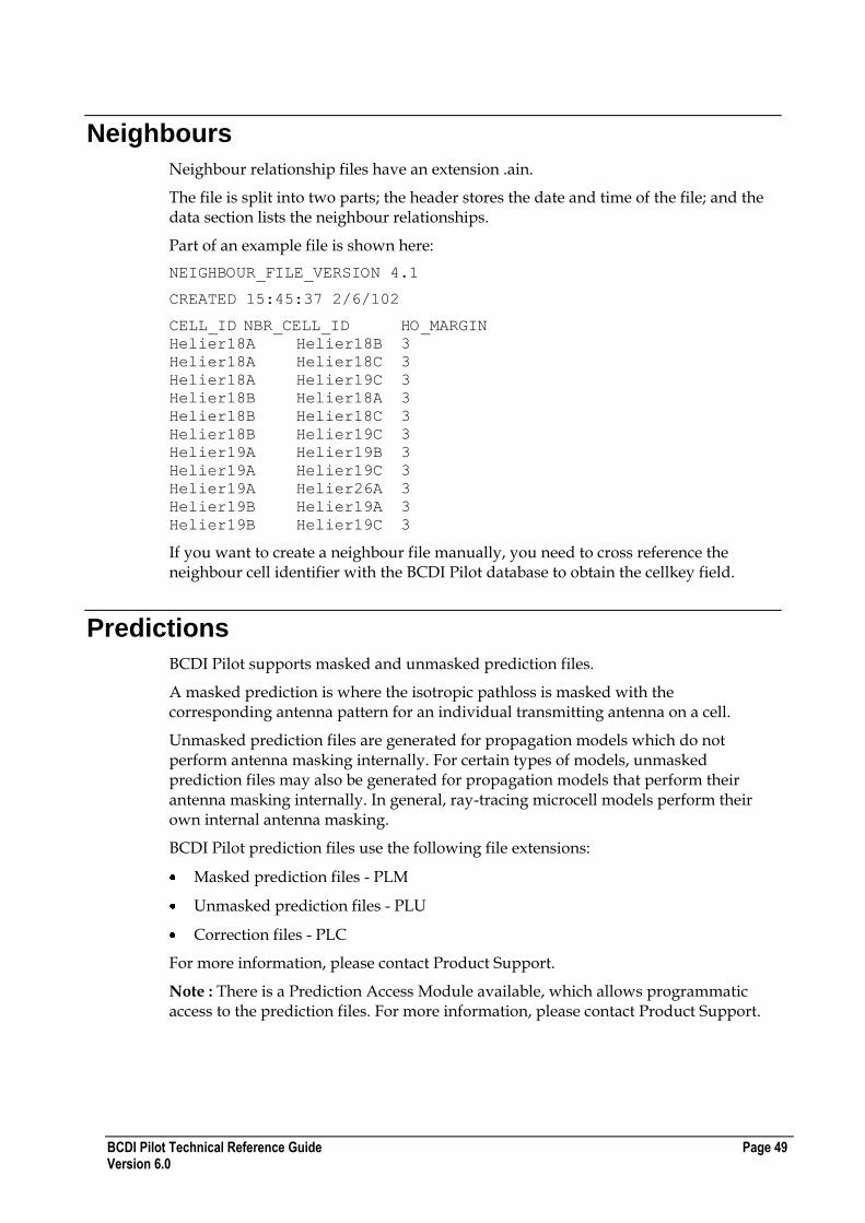
Neighbour relationship files have an extension .ain.
The file is split into two parts; the header stores the date and time of the file; and the data section lists the neighbour relationships.
Part of an example file is shown here:
NEIGHBOUR_FILE_VERSION 4.1
CREATED 15:45:37 2/6/102
CELL_ID NBR_CELL_ID HO_MARGIN
Helier18A Helier18B 3
Helier18A Helier18C 3
Helier18A Helier19C 3
Helier18B Helier18A 3
Helier18B Helier18C 3
Helier18B Helier19C 3
Helier19A Helier19B 3
Helier19A Helier19C 3
Helier19A Helier26A 3
Helier19B Helier19A 3
Helier19B Helier19C 3
If you want to create a neighbour file manually, you need to cross reference the neighbour cell identifier with the BCDI Pilot database to obtain the cellkey field.
Predictions
BCDI Pilot supports masked and unmasked prediction files.
A masked prediction is where the isotropic pathloss is masked with the corresponding antenna pattern for an individual transmitting antenna on a cell.
Unmasked prediction files are generated for propagation models which do not perform antenna masking internally. For certain types of models, unmasked prediction files may also be generated for propagation models that perform their antenna masking internally. In general, ray-tracing microcell models perform their own internal antenna masking.
BCDI Pilot prediction files use the following file extensions:
Masked prediction files - PLM
Unmasked prediction files - PLU
Correction files - PLC
For more information, please contact Product Support.
Note : There is a Prediction Access Module available, which allows programmatic access to the prediction files. For more information, please contact Product Support.

Page 50 BCDI Pilot Technical Reference Guide Version 6.0
Traffic Raster
A traffic raster consists of two files with the same name but different extensions:
A .tri file for the geo-reference information
A .trr file for the actual traffic raster data
TRI File Format
This information is contained in the TRI file:
Field Name Data Type Length (bytes) Description
Header CHAR 15 (Line Feed) Traffic File V3
Xmin INT 4 Space-separated minimum X region co-ordinate
Ymin INT 4 Space-separated maximum X region co-ordinate
Xmax INT 4 Space-separated minimum Y region co-ordinate
Ymax INT 4 Space-separated maximum Y region co-ordinate
Region size INT 4 Resolution (square size) of array (metres)
Create User CHAR 32 Name of the person who created the file
Create Date/Time CHAR 32 Date when array was created
Memory Size
Switching Type INT 4 Type of traffic where:
Circuit switched traffic = 0
Packet switched traffic = 1
HSCSD traffic = 2
3g traffic = 3
CDMA2000 traffic = 4
No of Terminals INT 4 Number of terminals spread in array
Timestamp INT 10 (Line Feed) Date and time when the file was created
MBHCR Floating Point value
ascii
(Line Feed)
Mean Busy Hour Capacity Requirement (used for GPRS and EGPRS only)
Comments CHAR 255 Optional comments field
This picture shows an example of a TRI file:

BCDI Pilot Technical Reference Guide Page 51 Version 6.0
TRR File Format
The TRR file stores raster data in binary format similar to that of height and clutter data. Each item of traffic must be an integer (four bytes):
Field Description
Traffic data Traffic data, in the following units:
Circuit switched traffic is in Timeslot Erlangs.
Packet switched traffic is in terminals.
HSCSD traffic is in User Erlangs.
3g traffic is in milli terminals per square km. To convert to terminals per pixel, multiply the area
represented by pixels in .
Note : These values are traffic densities per pixel and not absolute traffic per pixel.
This picture shows an example TRR file:
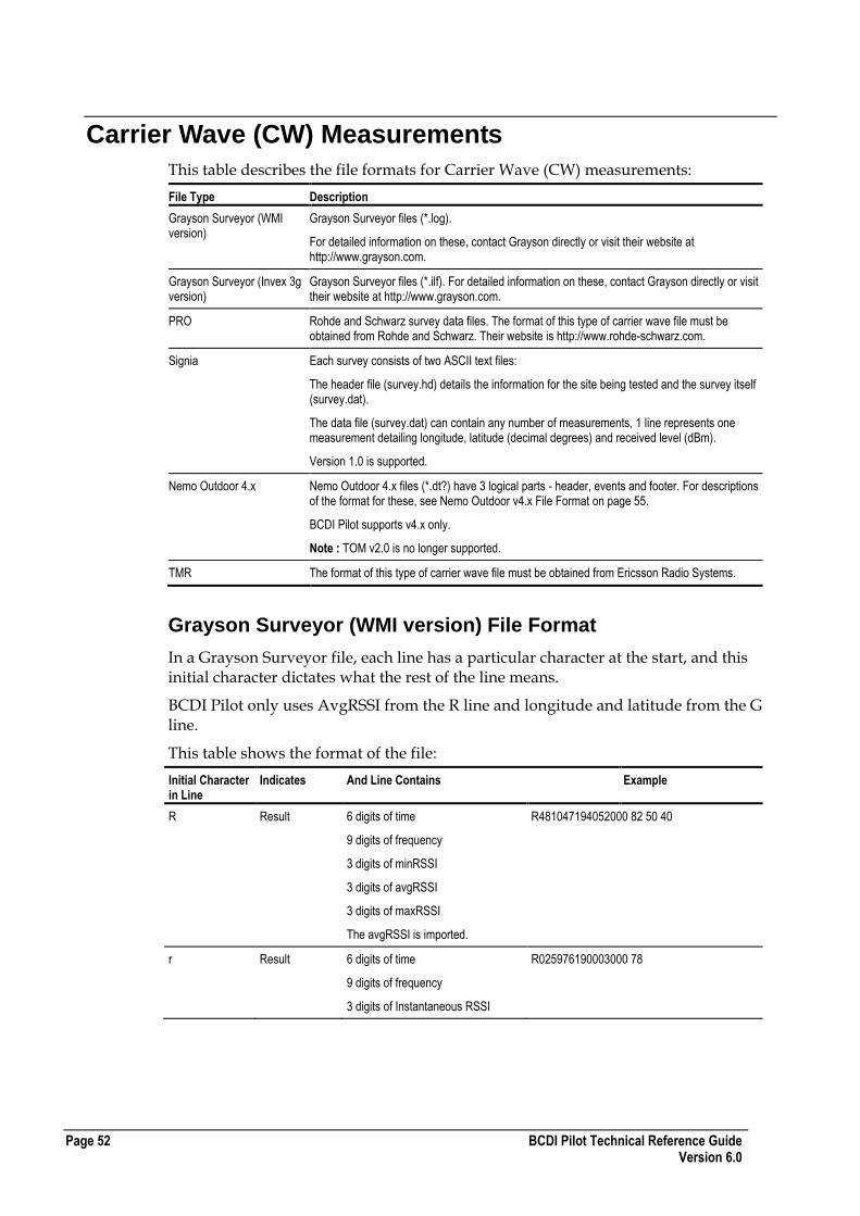
Page 52 BCDI Pilot Technical Reference Guide Version 6.0
Carrier Wave (CW) Measurements
This table describes the file formats for Carrier Wave (CW) measurements:
File Type Description
Grayson Surveyor (WMI version)
Grayson Surveyor files (*.log).
For detailed information on these, contact Grayson directly or visit their website at http://www.grayson.com.
Grayson Surveyor (Invex 3g version)
Grayson Surveyor files (*.ilf). For detailed information on these, contact Grayson directly or visit their website at http://www.grayson.com.
PRO Rohde and Schwarz survey data files. The format of this type of carrier wave file must be obtained from Rohde and Schwarz. Their website is http://www.rohde-schwarz.com.
Signia Each survey consists of two ASCII text files:
The header file (survey.hd) details the information for the site being tested and the survey itself (survey.dat).
The data file (survey.dat) can contain any number of measurements, 1 line represents one measurement detailing longitude, latitude (decimal degrees) and received level (dBm).
Version 1.0 is supported.
Nemo Outdoor 4.x Nemo Outdoor 4.x files (*.dt?) have 3 logical parts - header, events and footer. For descriptions of the format for these, see Nemo Outdoor v4.x File Format on page 55.
BCDI Pilot supports v4.x only.
Note : TOM v2.0 is no longer supported.
TMR The format of this type of carrier wave file must be obtained from Ericsson Radio Systems.
Grayson Surveyor (WMI version) File Format
In a Grayson Surveyor file, each line has a particular character at the start, and this initial character dictates what the rest of the line means.
BCDI Pilot only uses AvgRSSI from the R line and longitude and latitude from the G line.
This table shows the format of the file:
Initial Character in Line
Indicates And Line Contains Example
R Result 6 digits of time
9 digits of frequency
3 digits of minRSSI
3 digits of avgRSSI
3 digits of maxRSSI
The avgRSSI is imported.
R481047194052000 82 50 40
r Result 6 digits of time
9 digits of frequency
3 digits of Instantaneous RSSI
R025976190003000 78
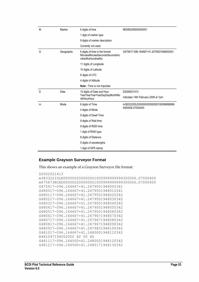
BCDI Pilot Technical Reference Guide Page 53 Version 6.0
M Marker 6 digits of time
1 digit of marker type
9 digits of marker description
Currently not used.
M005632N000000001
G Geographic 6 digits of time in the format MinutesMinutesSecondsSecondsHundredthsHundredths
11 digits of Longitude
10 digits of Latitude
6 digits of UTC
4 digits of Altitude
Note : Time is not imported.
G475917-096.164667+41.2479501948000341
D Date 10 digits of Date and Hour YearYearYearYearDayDayMonthMonthHourHour
D2006021413
indicates 14th February 2006 at 1pm
m Mode 6 digits of Time
4 digits of Mode
9 digits of Dwell Time
9 digits of Wait time
9 digits of RSSI time
1 digit of RSSI type
8 digits of Distance
5 digits of wavelengths
1 digit of GPS stamp
m383322IDLE000000200000001000999999999300006.07000400
Example Grayson Surveyor Format
This shows an example of a Grayson Surveyor file format:
D2002021413
m383322IDLE000000200000001000999999999300006.07000400
m475873RCRD000000200000001000999999999300006.07000400
G475917-096.164667+41.2479501948000341
G480017-096.164667+41.2479501948010341
G480117-096.164667+41.2479501948020342
G480217-096.164667+41.2479501948030342
G480317-096.164667+41.2479501948040342
G480417-096.164667+41.2479501948050342
G480517-096.164667+41.2479501948060342
G480617-096.164667+41.2479671948070342
G480717-096.164667+41.2479671948080342
G480817-096.164667+41.2479671948090342
G480917-096.164667+41.2479831948100342
G481017-096.164667+41.2480001948110342
R481047194052000 82 50 40
G481117-096.164500+41.2480001948120342
G481217-096.164500+41.2480171948130342

Page 54 BCDI Pilot Technical Reference Guide Version 6.0
Grayson Surveyor (Invex 3G version) File Format
These files come with a .ilf extension. The complete files can be read in using a tool by Grayson Wireless known as Invex 3G. The files contain much more than CW information but BCDI Pilot only uses the CW information from them. This can be obtained through using a COM dll that comes with Invex 3G. The ai_graysoninvex3g.dll will not work unless you have previously run the file GraysonCOM3.exe which comes with Invex 3G.
Signia Header File
In the Signia header file (which must be named *.hd), the values of items are space delimited and the file is terminated with a carriage return.
Numeric values should be given for Site_Longitude & Latitude, Tx_Azimuth, Tx_Power, Feeder_Length, Connector_Loss and Frequency.
Important : The Tx_Power line shows the transmit EiRP in dBm
Dates should be specified using four numbers, for example 2002.
The minimum data required for operation are the transmitter location, height and radiated power fields.
An example of a header file is:
SITE_ID X1234
SITE_NAME Demo
SITE_LONGITUDE -3.2755
SITE_LATITUDE 51.5829
SITE_TYPE Mast
TX_AZIMUTH 0
TX_TILT 0
TX_HEIGHT 25
TX_POWER 40
ANTENNA_TYPE Unknown
FEEDER_TYPE Unknown
FEEDER_LENGTH 28
CONNECTOR_LOSS 3
FREQUENCY 1800
OPERATOR Name of the operator here
COMMENTS Any comments to be added to the survey
DATE_START 12/4/2002
TIME_START 12:38:17
DATE_END 13/4/2002
TIME_END 14:38:17
Signia Data File
The Signia data file, (which must be named *.dat) can contain any number of measurements, 1 line represents one measurement detailing longitude, latitude (decimal degrees) and received level (dBm).
An example data file is:

BCDI Pilot Technical Reference Guide Page 55 Version 6.0
-6.262232 53.334252 -60.71 Start
-6.262663 53.334643 -62.85
-6.263292 53.334769 -63.54
-6.263575 53.335141 -78.34
-6.263649 53.335600 -84.59 Tag1
-6.263674 53.336079 -80.66
-6.263678 53.336544 -84.28
-6.263652 53.336861 -85.26
-6.263516 53.337424 -88.24
-6.263655 53.337582 -87.76
-6.263243 53.338007 -91.55 Tag2
-6.262852 53.338436 -90.85
-6.262592 53.338803 -87.45
-6.262284 53.339229 -88.63
-6.261901 53.339582 -89.21 Tag3
-6.260988 53.339910 -91.12
-6.260224 53.339838 -90.32
-6.259497 53.339662 -91.43
-6.25905 53.339759 -91.91
-6.25889 53.340232 -95.71 Finish
Nemo Outdoor v4.x File Format
The Nemo Outdoor v4.x file has three logical parts - header, events and footer.
Header
The header consists of several lines of variable length and includes information about measurement configuration. The first line in the header begins with *** and all other lines begin with # followed by a 2-character event identification sign.
The structure of first line is as follows:
***[pname(id)] [sw ver] ffver [ff ver] [date] [time]
where:
pname = product name of the measurement tool
(id) = possible identification number of the tool
sw ver = software version of the product (major.minor.build)
ff ver = measurement file format version
date = start date of measurement
time = start time of measurement
Events
An event is an ASCII string of unspecified length. All events are separated from each other with the new line character. Different fields in each event are separated by the space character. Each event can have different parameters that are to be stored after co-ordinate and time information on the same line. If the event parameter string contains spaces, then the individual parameter string must be placed between quotation marks.
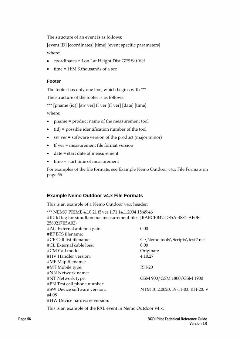
Page 56 BCDI Pilot Technical Reference Guide Version 6.0
The structure of an event is as follows:
[event ID] [coordinates] [time] [event specific parameters]
where:
coordinates = Lon Lat Height Dist GPS Sat Vel
time = H:M:S.thousands of a sec
Footer
The footer has only one line, which begins with ***
The structure of the footer is as follows:
*** [pname (id)] [sw ver] ff ver [ff ver] [date] [time]
where:
pname = product name of the measurement tool
(id) = possible identification number of the tool
sw ver = software version of the product (major.minor)
ff ver = measurement file format version
date = start date of measurement
time = start time of measurement
For examples of the file formats, see Example Nemo Outdoor v4.x File Formats on page 56.
Example Nemo Outdoor v4.x File Formats
This is an example of a Nemo Outdoor v4.x header:
*** NEMO PRIME 4.10.21 ff ver 1.71 14.1.2004 15:49:46 #ID Id tag for simultaneous measurement files: [BABCEB42-D85A-4884-AE0F-2580217E5A02} #AG External antenna gain: 0.00 #BF BTS filename: #CF Call list filename: C:\Nemo tools\Scripts\test2.nsf #CL External cable loss: 0.00 #CM Call mode: Originate #HV Handler version: 4.10.27 #MF Map filename: #MT Mobile type: RH-20 #NN Network name: #NT Network type: GSM 900/GSM 1800/GSM 1900 #PN Test call phone number: #SW Device software version: NTM 10.2.0020, 19-11-03, RH-20, V a4.08 #HW Device hardware version:
This is an example of the RXL event in Nemo Outdoor v4.x:
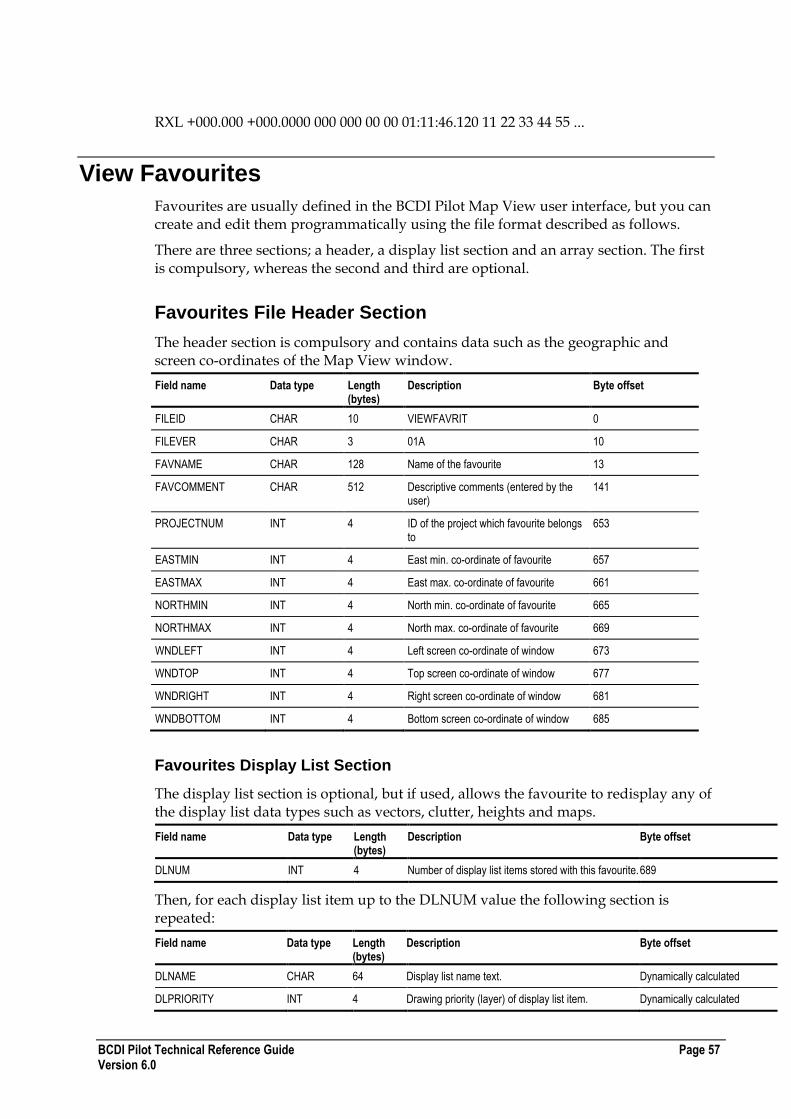
BCDI Pilot Technical Reference Guide Page 57 Version 6.0
RXL +000.000 +000.0000 000 000 00 00 01:11:46.120 11 22 33 44 55 ...
View Favourites
Favourites are usually defined in the BCDI Pilot Map View user interface, but you can create and edit them programmatically using the file format described as follows.
There are three sections; a header, a display list section and an array section. The first is compulsory, whereas the second and third are optional.
Favourites File Header Section
The header section is compulsory and contains data such as the geographic and screen co-ordinates of the Map View window.
Field name Data type Length (bytes)
Description Byte offset
FILEID CHAR 10 VIEWFAVRIT 0
FILEVER CHAR 3 01A 10
FAVNAME CHAR 128 Name of the favourite 13
FAVCOMMENT CHAR 512 Descriptive comments (entered by the user)
141
PROJECTNUM INT 4 ID of the project which favourite belongs to
653
EASTMIN INT 4 East min. co-ordinate of favourite 657
EASTMAX INT 4 East max. co-ordinate of favourite 661
NORTHMIN INT 4 North min. co-ordinate of favourite 665
NORTHMAX INT 4 North max. co-ordinate of favourite 669
WNDLEFT INT 4 Left screen co-ordinate of window 673
WNDTOP INT 4 Top screen co-ordinate of window 677
WNDRIGHT INT 4 Right screen co-ordinate of window 681
WNDBOTTOM INT 4 Bottom screen co-ordinate of window 685
Favourites Display List Section
The display list section is optional, but if used, allows the favourite to redisplay any of the display list data types such as vectors, clutter, heights and maps.
Field name Data type Length (bytes)
Description Byte offset
DLNUM INT 4 Number of display list items stored with this favourite. 689
Then, for each display list item up to the DLNUM value the following section is repeated:
Field name Data type Length (bytes)
Description Byte offset
DLNAME CHAR 64 Display list name text. Dynamically calculated
DLPRIORITY INT 4 Drawing priority (layer) of display list item. Dynamically calculated

Page 58 BCDI Pilot Technical Reference Guide Version 6.0
Favourites Arrays Section
The array section is optional, but if used, allows the favourite to redisplay pre-saved arrays.
Field name Data type Length (bytes)
Description Byte offset
ARRAYNUM SHORT 2 Number of array files stored with this favourite
Dynamically calculated
Then, for each array file list item up to the ARRAYNUM value the following section is repeated:
Field name Data type Length (bytes)
Description
ARRAYFNAME CHAR 255 Array filename (no path)
ARRAYTYPE INT 4 Type of array stored in file. Currently supported types:
1 = Coverage
2 = Interference
3 = Traffic
User-Defined Fields
Fields are defined in the Administrator tool. To do this:
In BCDI Pilot Administrator, from the Utilities menu, click Field Definer. Select the project in which you want to create or edit fields and create them as required.
You can also export and import the fields in the Field Definer and the flags.txt file used is described here. In the field file format:
A format version number begins the file.
Each group is listed, followed by the type of field it is, and then, if it is a picklist, the different options for it.
You can import files containing picklist fields without their options, but you cannot commit these types of field until you have added the options.
Any lines not starting with GROUP, FIELDTYPE, FLAG, Associations, or ASSOCIATION (all case-sensitive) will terminate ANY import and cause an "invalid flag file" error.
You cannot associate fields with PmP hubs, sectors or carriers.
You can still import previous file formats.

BCDI Pilot Technical Reference Guide Page 59 Version 6.0
An example field file is shown below:
Example field file format
The following formats are also supported:
Planet Flag Format
Planet Link Format
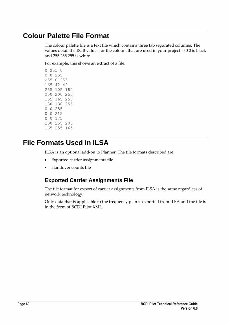
Page 60 BCDI Pilot Technical Reference Guide Version 6.0
Colour Palette File Format
The colour palette file is a text file which contains three tab separated columns. The values detail the RGB values for the colours that are used in your project. 0 0 0 is black and 255 255 255 is white.
For example, this shows an extract of a file:
0 255 0
0 0 255
255 0 255
165 42 42
255 105 180
200 200 255
165 165 255
130 130 255
0 0 255
0 0 215
0 0 175
200 255 200
165 255 165
File Formats Used in ILSA
ILSA is an optional add-on to Planner. The file formats described are:
Exported carrier assignments file
Handover counts file
Exported Carrier Assignments File
The file format for export of carrier assignments from ILSA is the same regardless of network technology.
Only data that is applicable to the frequency plan is exported from ILSA and the file is in the form of BCDI Pilot XML.
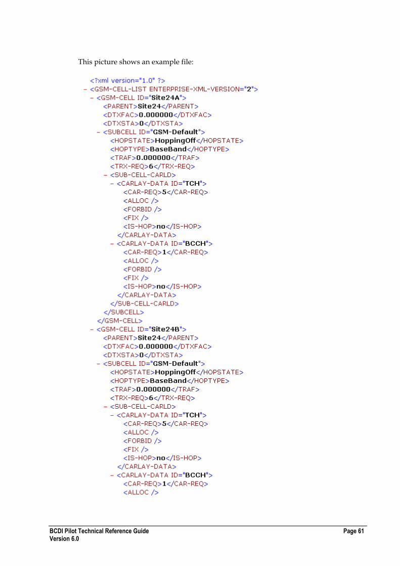
BCDI Pilot Technical Reference Guide Page 61 Version 6.0
This picture shows an example file:
Page 62 BCDI Pilot Technical Reference Guide Version 6.0
The following table describes the fields that are exported:
Field Description
GSM CELL ID The ID of the cell: string
PARENT The ID of the parent Site: string
DTXFAC DTX Factor: float
DTXSTA DTX State, on(1) or off(0): integer
SUBCELL ID ID of the sub-cell under the Cell: string
HOPSTATE Hopping on(1) or off(0): integer
HOPTYPE Hopping Type: integer
TRAF Traffic on the sub-cell: float
TRX-REQ Number of TRX required: integer
SUB-CELL-CARLD List of Carrier Layer Datas under SubCell
CARLAY-DATA ID ID of the carrier layer data: string
CAR-REQ Number of carriers required: integer
ALLOC List of allocated carriers
FORBID List of forbidden carriers
FIX List of fixed carrier
IS-HOP Whether this carrier layer data is hopping (No or Yes).
Handover Counts File
ILSA uses a handover counts file which you can export from OPTIMA or create yourself, following the same format.
The file is comma delimited with this header:
SCELL1,SITENAME1,BSC1,DCELL1,SITENAME2,BSC2,HOCNT1,HOSUCC1,HORE
T1,HODROP1,HOCNT2,HOSUCC2,HORET2,HODROP2
Each record has its own line with these fields in it. The fields that ILSA is interested in are:
SCELL1
DCELL1
HOCNT1
HOCNT2
This table shows the contents of the file:
Name Description
SCELL1 Source cell id.
SITENAME1 Source cell‟s sitename.
BSC1 Source cell‟s bsc name.
DCELL1 Neighbouring (destination) cell id.
SITENAME2 Neighbouring cell‟s sitename.
BSC2 Neighbouring cell‟s bsc name.
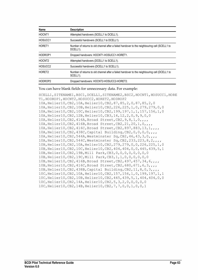
BCDI Pilot Technical Reference Guide Page 63 Version 6.0
Name Description
HOCNT1 Attempted handovers (SCELL1 to DCELL1).
HOSUCC1 Successful handovers (SCELL1 to DCELL1).
HORET1 Number of returns to old channel after a failed handover to the neighbouring cell (SCELL1 to DCELL1).
HODROP1 Dropped handovers: HOCNT1-HOSUCC1-HORET1.
HOCNT2 Attempted handovers (DCELL1 to SCELL1).
HOSUCC2 Successful handovers (DCELL1 to SCELL1).
HORET2 Number of returns to old channel after a failed handover to the neighbouring cell (DCELL1 to SCELL1).
HODROP2 Dropped handovers: HOCNT2-HOSUCC2-HORET2.
You can have blank fields for unnecessary data. For example:
SCELL1,SITENAME1,BSC1,DCELL1,SITENAME2,BSC2,HOCNT1,HOSUCC1,HORE
T1,HODROP1,HOCNT2,HOSUCC2,HORET2,HODROP2
10A,Helier10,CB2,10A,Helier10,CB2,87,85,2,0,87,85,2,0
10A,Helier10,CB2,10B,Helier10,CB2,226,225,1,0,279,279,0,0
10A,Helier10,CB2,10C,Helier10,CB2,199,197,1,1,157,156,1,0
10A,Helier10,CB2,12B,Helier10,CB3,14,12,2,0,9,9,0,0
10A,Helier10,CB2,416A,Broad Street,CB2,9,8,1,0,,,,
10A,Helier10,CB2,416B,Broad Street,CB2,21,20,1,0,,,,
10A,Helier10,CB2,416C,Broad Street,CB2,897,883,13,1,,,,
10A,Helier10,CB2,438C,Capital Building,CB2,0,0,0,0,,,,
10A,Helier10,CB2,544A,Westminster Sq,CB2,46,43,3,0,,,,
10A,Helier10,CB2,544C,Westminster Sq,CB2,233,223,8,2,,,,
10B,Helier10,CB2,10A,Helier10,CB2,279,279,0,0,226,225,1,0
10B,Helier10,CB2,10C,Helier10,CB2,404,404,0,0,445,439,5,1
10B,Helier10,CB2,19B,Mill Park,CB3,0,0,0,0,0,0,0,0
10B,Helier10,CB2,19C,Mill Park,CB3,1,1,0,0,0,0,0,0
10B,Helier10,CB2,416B,Broad Street,CB2,497,457,34,6,,,,
10B,Helier10,CB2,416C,Broad Street,CB2,680,671,6,3,,,,
10B,Helier10,CB2,438B,Capital Building,CB2,11,8,0,3,,,,
10C,Helier10,CB2,10A,Helier10,CB2,157,156,1,0,199,197,1,1
10C,Helier10,CB2,10B,Helier10,CB2,445,439,5,1,404,404,0,0
10C,Helier10,CB2,14A,Helier10,CB2,5,3,2,0,0,0,0,0
10C,Helier10,CB2,14B,Helier10,CB2,7,7,0,0,1,0,0,1

Page 64 BCDI Pilot Technical Reference Guide Version 6.0
Live Traffic File Formats for 2g Networks
You can import measured traffic from a text file and use 'live' rather than 'estimated' traffic in traffic spreading. For GPRS and HSCSD, live traffic is the total traffic caused by any GPRS (or HSCSD) terminal types on sub-cells. Live HSCSD traffic is measured and distributed in Erlangs.
The live traffic file formats supported are:
Format File Type Contains
NMS 2000 *.nms Live NMS2000 traffic information
Can contain circuit-switched, HSCSD and GPRS traffic
Uses LAC and GSMID
GSM *.gts Live GSM traffic
Can contain circuit-switched, HSCSD and GPRS traffic
Uses LAC, GSMID and Cell Layer Name
General Purpose *.tps GSM, Analog or PMR/TETRA/iDEN traffic
Can contain circuit-switched, HSCSD and GPRS traffic
Uses CellID and Cell Layer Name
NMS File Format (*.nms)
The NMS file format is as shown here:
LAC white-space GSMID white-space CSTraffic white-space
HSCSDTraffic white-space GPRSTraffic
If there is no data for the CSTraffic or HSCSDTraffic or GPRSTraffic then the column must contain a - (hyphen).
GSM File Format (*.gts)
The GSM file format is as shown here:
LAC white-space GSMID white-space Cell Layer Name white-space
CSTraffic white-space HSCSDTraffic white-space GPRSTraffic
If there is no data for the CSTraffic or HSCSDTraffic or GPRSTraffic then the column must contain a - (hyphen).
TPS File Format (*.tps)
The TPS file format is a general purpose format which can contain GSM, EGPRS, PMR/TETRA/iDEN or AMPS live traffic. This file starts with this header:
# AIRCOM V1.0 Live Traffic File
And contains data in this format:
CELLID white-space Cell Layer Name white-space CSTraffic white-
space HSCSDTraffic white-space GPRSTraffic white-space
EGPRSTraffic
BCDI Pilot Technical Reference Guide Page 65 Version 6.0
The HSCSD Traffic, GPRS Traffic and EGPRS columns may be left blank unless there is data in a later column, in which case they must contain a - (hyphen). This flexibility allows for network types that do not support HSCSD or GPRS, such as PMR/TETRA/iDEN or AMPS.
Important : Ensure there are no spaces at the end of any of the rows (in particular, the header row), otherwise the import will fail.
Live Traffic File Formats for 3g Networks
You can import measured traffic from files and use 'live' rather than 'estimated' traffic in traffic spreading.
For 3g networks, there are two types of live traffic import files that can be used when creating a Traffic Raster:
*.tpc
*.cbc and *.cbd (used together)
Live Traffic File Formats for WiMAX Networks
You can import measured traffic from files and use 'live' rather than 'estimated' traffic in traffic spreading.
For WiMAX (Fixed or Mobile) networks, there is one type of live traffic import file that can be used when creating a Traffic Raster:
*.tpc
About the *.tpc File Format
The file defines the number of terminals to spread for each cell. This file format is an extension of the BCDI Pilot general purpose live traffic import file (*.tps).
The file format is as follows:
The first row is the header
The second row contains the word 'cell' (or 'sector' if the traffic to be spread is CDMA2000 traffic), followed by the word 'Terminals'
The remaining rows then contain the traffic data to be spread. The format for each technology type are described in this table:
Technology Format
UMTS UMTS Cell Name (white-space) UMTS Traffic (Terminals)
CDMA2000 CDMA2000 Sector Name (white-space) CDMA2000 Traffic (Terminals)
EV-DO UMTS Cell Name (white-space) UMTS Traffic (Terminals)
WiMAX WiMAX Cell Name (white-space) WiMAX Traffic (Terminals)
Note : For all these technologies, the units of traffic is Terminals.
Important : Ensure there are no spaces at the end of any of the rows (in particular, the header row), otherwise the import will fail.
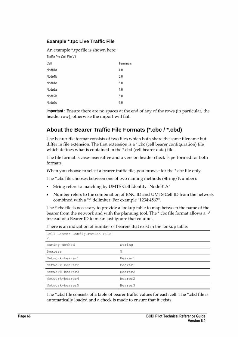
Page 66 BCDI Pilot Technical Reference Guide Version 6.0
Example *.tpc Live Traffic File
An example *.tpc file is shown here:
Traffic Per Cell File V1
Cell Terminals
Node1a 4.0
Node1b 5.0
Node1c 6.0
Node2a 4.0
Node2b 5.0
Node2c 6.0
Important : Ensure there are no spaces at the end of any of the rows (in particular, the header row), otherwise the import will fail.
About the Bearer Traffic File Formats (*.cbc / *.cbd)
The bearer file format consists of two files which both share the same filename but differ in file extension. The first extension is a *.cbc (cell bearer configuration) file which defines what is contained in the *.cbd (cell bearer data) file.
The file format is case-insensitive and a version header check is performed for both formats.
When you choose to select a bearer traffic file, you browse for the *.cbc file only.
The *.cbc file chooses between one of two naming methods (String/Number):
String refers to matching by UMTS Cell Identity "NodeB1A"
Number refers to the combination of RNC ID and UMTS Cell ID from the network combined with a ":" delimiter. For example "1234:4567".
The *.cbc file is necessary to provide a lookup table to map between the name of the bearer from the network and with the planning tool. The *.cbc file format allows a '-' instead of a Bearer ID to mean just ignore that column.
There is an indication of number of bearers that exist in the lookup table:
Cell Bearer Configuration File
V1
Naming Method String
Bearers 5
Network-bearer1 Bearer1
Network-bearer2 Bearer1
Network-bearer3 Bearer2
Network-bearer4 Bearer2
Network-bearer5 Bearer3
The *.cbd file consists of a table of bearer traffic values for each cell. The *.cbd file is automatically loaded and a check is made to ensure that it exists.
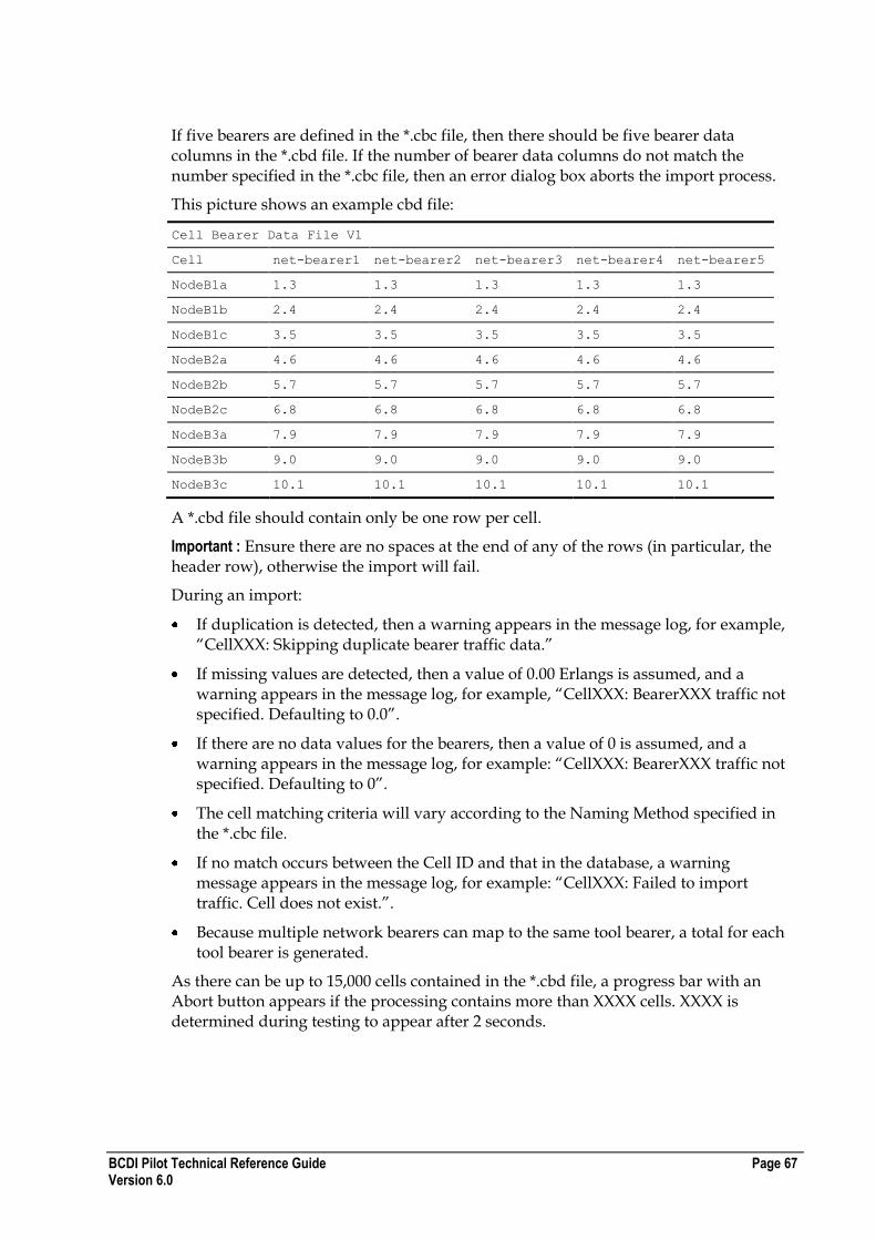
BCDI Pilot Technical Reference Guide Page 67 Version 6.0
If five bearers are defined in the *.cbc file, then there should be five bearer data columns in the *.cbd file. If the number of bearer data columns do not match the number specified in the *.cbc file, then an error dialog box aborts the import process.
This picture shows an example cbd file:
Cell Bearer Data File V1
Cell net-bearer1 net-bearer2 net-bearer3 net-bearer4 net-bearer5
NodeB1a 1.3 1.3 1.3 1.3 1.3
NodeB1b 2.4 2.4 2.4 2.4 2.4
NodeB1c 3.5 3.5 3.5 3.5 3.5
NodeB2a 4.6 4.6 4.6 4.6 4.6
NodeB2b 5.7 5.7 5.7 5.7 5.7
NodeB2c 6.8 6.8 6.8 6.8 6.8
NodeB3a 7.9 7.9 7.9 7.9 7.9
NodeB3b 9.0 9.0 9.0 9.0 9.0
NodeB3c 10.1 10.1 10.1 10.1 10.1
A *.cbd file should contain only be one row per cell.
Important : Ensure there are no spaces at the end of any of the rows (in particular, the header row), otherwise the import will fail.
During an import:
If duplication is detected, then a warning appears in the message log, for example, “CellXXX: Skipping duplicate bearer traffic data.”
If missing values are detected, then a value of 0.00 Erlangs is assumed, and a warning appears in the message log, for example, “CellXXX: BearerXXX traffic not specified. Defaulting to 0.0”.
If there are no data values for the bearers, then a value of 0 is assumed, and a warning appears in the message log, for example: “CellXXX: BearerXXX traffic not specified. Defaulting to 0”.
The cell matching criteria will vary according to the Naming Method specified in the *.cbc file.
If no match occurs between the Cell ID and that in the database, a warning message appears in the message log, for example: “CellXXX: Failed to import traffic. Cell does not exist.”.
Because multiple network bearers can map to the same tool bearer, a total for each tool bearer is generated.
As there can be up to 15,000 cells contained in the *.cbd file, a progress bar with an Abort button appears if the processing contains more than XXXX cells. XXXX is determined during testing to appear after 2 seconds.

Page 68 BCDI Pilot Technical Reference Guide Version 6.0
BCDI Pilot Technical Reference Guide Page 69 Version 6.0
XML File Formats
This chapter provides a full and detailed description of the XML file format used in BCDI Pilot as well as a description of the constraints on exporting and importing.
In This Section
Getting Started with XML 69 About the XML Index File 70 Handling Import Conflicts 71 Editing XML Files 72 Special Character Sets 73 XML Project File Formats 73 XML Configuration File Formats 180 XML ADVANTAGE File Formats 253
Getting Started with XML
To get you started, the following information gives some helpful pointers of some of the formats used.
General XML Formats
A standard XML shorthand for indicating that the tag is empty is shown as <antenna/>
A start tag must have a matching end tag
There must be no overlapping tags, that is a tag that opens inside another tag must be closed before the containing tag closes
BCDI Pilot Specific XML Formats
RO in a tag indicates it is read-only and can only be used for export.
For example, <DTM-RO> is using the DTM from the Map Data, and hence is read-only. However not all tags where this is true have RO in the tag.
If the tag <ACT-DTM> contains -9999.000000 that indicates that the DTM will be used instead
A P P E N D I X C
Page 70 BCDI Pilot Technical Reference Guide Version 6.0
About the XML Index File
The XML Importer recognises the index file as being a file with the word INDEX
(capitalized) in its name, for example myINDEXfile.xml,INDEX.xml and _INDEX-
001.xml.
This means that any files that contain project or config data should not contain INDEX in the file name. However, lower case or title case variations are allowed, so the
following names would be acceptable: PROPERTY-LIST-index.xml, MSC
Index.xml and CELLS iNdEx.xml.
The index file is not compulsory to perform the selection of .xml files to import. You can do one of these:
Select just the INDEX file.
Select a multiple selection of xml data files.
Select data files and the INDEX file together.
However, if you do select data files and the index file together, the XML Importer would be expecting the index file to refer to a different selection of files than those data files selected at the same time. Duplicate selections are ignored, for example, if the selection made from the import dialog is this:
PROPERTY-LIST001.xml
MSC-LIST001.xml
BSC-LIST001.xml
INDEX001.xml
The index file also points to the other 3 files selected, then it will be ignored.
How Do I Reference Data Files in the Index File?
Data files can be referenced by the INDEX file using absolute or relative network path names, for example: <?xml version="1.0"?>
<INDEX>
<GSM-CELL-LIST FILENAME="johns cells.xml"/>
<GSM-CELL-LIST FILENAME="c:\xml\mikes cells.xml"/>
<GSM-CELL-LIST FILENAME="\\steve\share\steves cells.xml"/>
<GSM-CELL-LIST FILENAME="\\andy\xml\andys cells.xml"/>
</INDEX>
Each element within the INDEX element should be named after a data list, being the root tag of an BCDI Pilot XML file, such as:
GSM-CELL-LIST
MSC-LIST
NODEB-LIST
BCDI Pilot Technical Reference Guide Page 71 Version 6.0
Handling Import Conflicts
All importing data is identified by its unique ID attribute. If this ID already exists in the project into which you are importing, the XML Importer will give you the choice of the following:
Leave - Skip the import of this particular object.
Merge - Import all object‟s fields present in the XML file to existing object. Fields not listed will be ignored.
Stop -Terminate import at this point without importing current object.
Replace - Resets existing object‟s data to default initial values then imports all object‟s fields present in the XML file to existing object. Fields not present in the XML file will be ignored and will remain as default initial values.
Note : Replace does not delete objects. For example, importing an empty list (for example, <PROPERTY-LIST/>) will NOT remove all Properties.
XML Import Errors
If you encounter any of the errors described in this section, and you choose to ignore them, you will have the option to Apply to All. If you select this option, then all occurrences of the currently conflicting type will be acted upon in the same manner.
The following errors are possible:
Error Description
Object Missing ID All importing objects are identified via an ID, which is generally situated as an attribute to the element‟s root tag, for example:
<NODE-B ID=”QX_1098LM”>
If the ID is omitted, the element will not be imported.
Permission Required If a user does not have sufficient database privileges granted to edit or create a particular object, then they will also be prevented from importing that object type via the XML Importer.
Database Error If a database error occurs during the import of an object, you are notified and given the option to stop the import.
Dependency Not Found If an element‟s existence in a project is logically or physically dependent upon another parent element, the import might fail if either:
The ID of the parent is omitted from the XML import file
The ID of the parent is not found in the current project
What are the Network Dependencies?
This table describes the network dependencies:
Element Dependencies
BSC MSC, Property
Cell Site BSC, Property
Distribution Node BSC, Property
GSM Cell Cell Site
Repeater GSM Cell, Property
Page 72 BCDI Pilot Technical Reference Guide Version 6.0
Wideband Repeater Cell, Property
CDMA Repeater CDMA Sector, Property
Cell Node
WMSC, RNC, SGSN Log Net PLMN, Property
PtP Intercon Property (End A & End B)
PmP Intercon Property (End A & End B)
PmP Hub Property
PtPLinkend PtPIntercon, Property
PtPHubLinkend PtPIntercon, Property
Editing XML Files
You can edit the exported XML files in any manner if the hierarchy of the elements will remain correct. Any non-required elements or attributes can be omitted if the remaining structure will be preserved.
Importing XML - Example 1
The following will successfully import a new property to a blank project, setting the Contact to John, if John exists as a contact in the Project Configuration: <?xml version="1.0"?>
<PROPERTY-LIST ENTERPRISE-XML-VERSION="1">
<PROPERTY ID="NewProperty">
<CONTACT>John</CONTACT>
<LOCATION TYPE="ABS" UNIT="decLL">†
<X>-7.889</X>
<Y>49.67152</Y>
</LOCATION>
</PROPERTY>
</PROPERTY-LIST>
Importing XML - Example 2
This example shows the operations occurring separately for 2 cell sites but they could be done in one operation.
Site0 currently exists logically on BSC0 in the Project and Site1 exists physically on Property1. Importing the following via a Merge will re-parent Site0 to BSC1 and relocate Site1 to Property0:
<?xml version="1.0"?> <CELL-SITE-LIST ENTERPRISE-XML-VERSION="1">
<CELL-SITE ID="Site0"><PARENT>BSC1</PARENT></CELL-SITE>
<CELL-SITE ID="Site1"><PROPERTY>PROPERTY2</PROPERTY></CELL-SITE>
</CELL-SITE-LIST>
Note : If Replace was the import option then all other data would revert to initial/default values. Merging will not affect any other data.
BCDI Pilot Technical Reference Guide Page 73 Version 6.0
Importing XML - Example 3
The following is imported using Merge. Before importing, Cell Site0A is using the Antenna defined by Slot 101 (antenna_Y). The import will alter the slot to be using the antenna which referred to by slot 967 (antenna_X).
The actual slot number is not used due to the fact that slots used in the cell layer ANTENNA-CONFIG refer to slots available as specified by the cell ANTENNA-CONFIG. The slot numbers are implied by the order they are listed by the ANTENNA-CONFIG at the cell level.
In addition, the layer GSM-Default specifies that the propagation model should be over-ridden at the layer level. <?xml version="1.0"?>
<GSM-CELL-LIST ENTERPRISE-XML-VERSION="2">
<GSM-CELL ID="Site0A">
<ANTENNA-CONFIG>
<!-- order implies slot numbers, where slot 2 is ignored -->
<ANTENNA SLOT=”967”><TYPE>antenna_X</TYPE></ANTENNA>
<ANTENNA/>
<ANTENNA SLOT=”101”><TYPE>antenna_Y</TYPE></ANTENNA>
</ANTENNA-CONFIG>
<SUBCELL ID="GSM-Default">
<MODEL>New Model</MODEL>
<OVERRIDE_MODEL>ModelOn</OVERRIDE_MODEL>
<ANTENNA-CONFIG>
<!-- order is not relevant here -->
<SLOT USE=”NO”>101</SLOT>
<SLOT USE=”YES”>967</SLOT>
</ANTENNA-CONFIG>
</SUBCELL>
</GSM-CELL>
</GSM-CELL-LIST>
Special Character Sets
For European languages using characters outside the normal English character set, the processing instruction should contain the following encoding attribute: <?xml version="1.0" encoding="ISO-8859-1"?>
Examples of special characters are ë, á, å and so on.
XML Project File Formats
This section describes the XML project file formats for the network elements in BCDI Pilot.
Note : Template XML files are not specifically detailed here. This is because they are cut down versions of the main XML files. The exceptions to this are cell sites', nodes' and CDMA2000 BSs' XML files which as well as containing their own data, also contain cut down versions of the cell data associated with those types.
Page 74 BCDI Pilot Technical Reference Guide Version 6.0
Property XML File Format
The following table describes the XML file format for Properties:
Required Tags ID attribute
Comments The LOCATION block has two attributes :
TYPE = ABS | REL
UNIT = decLL | LL | EN
And the X and Y co-ordinates should reflect the units specified.
The <E> and <N> tags exported by BCDI Pilot Version 4.0 are still supported, hence no change in version number.
If this block is omitted from the PROPERTY, the default co-ordinates of 0.0,0.0 will be used.
MAST-MOUNT can be Rooftop (1), Wall (3), Pole (2), Ground (0)
Enumerated Values CANDSTATUS
[CANDIDATE | NOMINAL | PREFERRED | NOT_USED]
MAST-MOUNT
[ 0 | 1 | 2 | 3 ]
Example Property XML File
The following section of code shows an example Property XML file: <?xml version="1.0"?>
<PROPERTY-LIST ENTERPRISE-XML-VERSION="2">
<PROPERTY ID="PROPERTY2">
<SECURITY-RO>
<OWNER>b</OWNER>
<GROUP>All</GROUP>
<WRITE-PERMS OWNER="YES" GROUP="YES" ALL="YES"/>
<CREATED>2004-05-10 14:16:52 b</CREATED>
<MODIFIED>2004-05-11 09:58:14 b</MODIFIED>
</SECURITY-RO>
<COMMENTS/>
<AVAIL-HGHT>1.000000</AVAIL-HGHT>
<ADDR1>Line1</ADDR1>
<ADDR2>Line2</ADDR2>
<TOWN>Line3</TOWN>
<PROV>Line4</PROV>
<POSTCODE>Line5</POSTCODE>
<CONTACT>Unknown</CONTACT>
<LOCATION TYPE="ABS" UNIT="decLL">
<X>-2.09626527</X>
<Y>49.22955199</Y>
</LOCATION>
<LINKEND-PTP>Vigants : End B (Property2)</LINKEND-PTP>
<LINKEND-PTP>Link2 : End A (Property2)<LINKEND-PTP>
<ACT-DTM>9999.000000</ACT-DTM>
<DTM-RO>9999.00000</DTM-RO>
<SEARCH>0.000000</SEARCH>
<USE2D>no</USE2D>
<CANDSTATUS>NOT_USED</CANDSTATUS>
<MTTR>12.000000</MTTR>
<BLDG-HGHT>0</BLDG-HGHT>
<ASSOC-MAST>Mast0</ASSOC-MAST>
<ASSOC-MAST>21007417</ASSOC-MAST>
<MAST-MOUNT>0</MAST-MOUNT>
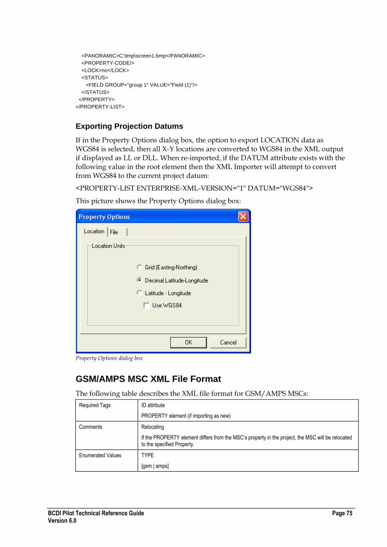
BCDI Pilot Technical Reference Guide Page 75 Version 6.0
<PANORAMIC>C:\tmp\screen1.bmp</PANORAMIC>
<PROPERTY-CODE/>
<LOCK>no</LOCK>
<STATUS>
<FIELD GROUP="group 1" VALUE="Field (1)"/>
</STATUS>
</PROPERTY>
</PROPERTY-LIST>
Exporting Projection Datums
If in the Property Options dialog box, the option to export LOCATION data as WGS84 is selected, then all X-Y locations are converted to WGS84 in the XML output if displayed as LL or DLL. When re-imported, if the DATUM attribute exists with the following value in the root element then the XML Importer will attempt to convert from WGS84 to the current project datum:
<PROPERTY-LIST ENTERPRISE-XML-VERSION="1" DATUM="WGS84">
This picture shows the Property Options dialog box:
Property Options dialog box
GSM/AMPS MSC XML File Format
The following table describes the XML file format for GSM/AMPS MSCs:
Required Tags ID attribute
PROPERTY element (if importing as new)
Comments Relocating
If the PROPERTY element differs from the MSC‟s property in the project, the MSC will be relocated to the specified Property.
Enumerated Values TYPE
[gsm | amps]
Page 76 BCDI Pilot Technical Reference Guide Version 6.0
Example GSM/AMPS MSC XML File
The following section of code shows an example GSM/AMPS MSC XML file: <?xml version="1.0"?>
<MSC-LIST ENTERPRISE-XML-VERSION="1">
<MSC ID="MSC0">
<TYPE>gsm</TYPE>
<SECURITY-RO>
<NAME1>aa</NAME1>
<NAME2>bb</NAME2>
<COMMENTS/>
<PROPERTY>Property2</PROPERTY>
<FREQBAND>1</FREQBAND>
<STATUS>
<FLAG GROUP="GSM_EQUIPMENT" VALUE="-"/>
</STATUS>
</MSC>
</MSC-LIST>
GSM BSC XML File Format
The following table describes the XML file format for GSM BSCs:
Required Tags ID attribute
PROPERTY element (if importing as new)
Comments Reparenting (during a MERGE or REPLACE) - The PARENT element should contain the ID of a valid MSC existing in the project. If the BSC exists in the project already and the MSC element differs from that which it is currently situated on, it will be logically relocated to the specified MSC.
Relocating - If the PROPERTY element differs from the BSC‟s property in the project, the BSC will be relocated to the specified Property.
PARENT not specified - If the parent element is omitted but the BSC does not already exist in the project, a dummy MSC will be created and added to the project at the location specified by the BSC‟s PROPERTY element.
Enumerated Values None
Example GSM BSC XML File
The following section of code shows an example GSM BSC XML file: <?xml version="1.0"?>
<BSC-LIST ENTERPRISE-XML-VERSION="1">
<BSC ID="BSC0">
<PARENT>MSC0</PARENT>
<BSC-ID>100</BSC-ID>
<SMLC>SMLC0</SMLC>
<SECURITY-RO>
<OWNER>b</OWNER>
<GROUP>All</GROUP>
<WRITE-PERMS OWNER="YES" GROUP="YES" ALL="YES"/>
<CREATED>2004-05-10 14:16:54 b</CREATED>
<MODIFIED>2004-05-10 16:24:22 b</<MODIFIED>
</SECURITY-RO>
<NAME1>aa</NAME1/>
<NAME2>bb</NAME2>
<COMMENTS/>
<PROPERTY>Property1</PROPERTY>

BCDI Pilot Technical Reference Guide Page 77 Version 6.0
<FREQBAND>1</FREQBAND>
</STATUS>
</BSC>
</BSC-LIST>
GSM/AMPS Cell Site XML File Format
The following table describes the XML file format for GSM/AMPS cell sites:
Required Tags ID attribute
PROPERTY element (if importing as new)
Comments Reparenting - The PARENT element should contain the ID of a valid BSC existing in the project. If the CellSite exists in the project already and the BSC element differs from that which it is currently situated on, it will be logically relocated to the specified BSC. The same goes for the MSC element (AMPS network).
Relocating - If the PROPERTY element differs from the CellSite‟s property in the project, the CellSite will be relocated to the specified Property.
PARENT not specified - If the parent element is omitted but the CellSite does not already exist in the project, a dummy BSC will be created and added to the project at the location specified by the BSC‟s PROPERTY element. In addition, if a suitable MSC is not found in the project by the XML Importer, one will be created for the BSC to parent.
MSC not specified - If the analogue MSC is not specified by the XML, a dummy will be created for the cellsite to parent to.
Enumerated Values BCF-TYPE
[ 2nd gen. Base Station | InSite | Metro Site | PrimeSite | Talk Family | UltraSite ]
Example GSM/AMPS Cell Site XML File
The following section of code shows an example GSM/AMPS cell site XML file: <?xml version="1.0"?>
<CELL-SITE-LIST ENTERPRISE-XML-VERSION="1">
<CELL-SITE ID="Site0">
<PARENT>BSC0</PARENT>
<SECURITY-RO>
<OWNER>b</OWNER>
<GROUP>All</GROUP>
<WRITE-PERMS OWNER="YES" GROUP="YES" ALL="YES"/>
<CREATED>2004-05-10 14:16:54 b</CREATED>
<MODIFIED>2004-05-10 17:07:13 b</MODIFIED>
</SECURITY-RO>
<NAME1>aa</NAME1/>
<NAME2>bb</NAME2>
<COMMENTS/>
<PROPERTY>Property2</PROPERTY>
<FREQBAND>1</FREQBAND>
<STATUS/>
<FIELD GROUP="group 1" VALUE="Field (1)"/>
</STATUS>
<CABIN>Cabin0</CABIN>
<BTS>BTS0</BTS>
<MAST>Mast0</MAST>
<BTS-FIXED>NO</BTS-FIXED>
<PRED-RAD>10000</PRED-RAD>
<HEX-RAD>1000.0</HEX-RAD>
<PRED-RES>50</PRED-RES>
<MSC>MSC1</MSC>
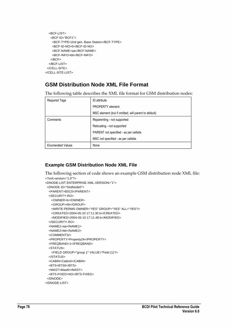
Page 78 BCDI Pilot Technical Reference Guide Version 6.0
<BCF-LIST>
<BCF ID="BCF1">
<BCF-TYPE>2nd gen. Base Station</BCF-TYPE>
<BCF-ID-NO>0</BCF-ID-NO>
<BCF-NAME>aa</BCF-NAME>
<BCF-INFO>bb</BCF-INFO>
</BCF>
</BCF-LIST>
</CELL-SITE>
</CELL-SITE-LIST>
GSM Distribution Node XML File Format
The following table describes the XML file format for GSM distribution nodes:
Required Tags ID attribute
PROPERTY element
MSC element (but if omitted, will parent to default)
Comments Reparenting - not supported
Relocating - not supported
PARENT not specified - as per cellsite
MSC not specified - as per cellsite.
Enumerated Values None
Example GSM Distribution Node XML File
The following section of code shows an example GSM distribution node XML file: <?xml version="1.0"?>
<DNODE-LIST ENTERPRISE-XML-VERSION="1">
<DNODE ID="DistNode0">
<PARENT>BSC0</PARENT>
<SECURITY-RO>
<OWNER>b</OWNER>
<GROUP>All</GROUP>
<WRITE-PERMS OWNER="YES" GROUP="YES" ALL="YES"/>
<CREATED>2004-05-10 17:11:30 b</CREATED>
<MODIFIED>2004-05-10 17:11:48 b</MODIFIED>
</SECURITY-RO>
<NAME1>aa</NAME1>
<NAME2>bb</NAME2>
<COMMENTS/>
<PROPERTY>Property24</PROPERTY>
<FREQBAND>1</FREQBAND>
<STATUS>
<FIELD GROUP="group 1" VALUE="Field (1)"/>
</STATUS>
<CABIN>Cabin0</CABIN>
<BTS>BTS0</BTS>
<MAST>Mast0</MAST>
<BTS-FIXED>NO</BTS-FIXED>
</DNODE>
</DNODE-LIST>
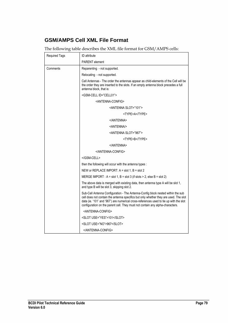
BCDI Pilot Technical Reference Guide Page 79 Version 6.0
GSM/AMPS Cell XML File Format
The following table describes the XML file format for GSM/AMPS cells:
Required Tags ID attribute
PARENT element
Comments Reparenting - not supported.
Relocating - not supported.
Cell Antennas - The order the antennas appear as child-elements of the Cell will be the order they are inserted to the slots. If an empty antenna block precedes a full antenna block, that is:
<GSM-CELL ID=”CELL01”>
<ANTENNA-CONFIG>
<ANTENNA SLOT=”101”>
<TYPE>A</TYPE>
</ANTENNA>
<ANTENNA/>
<ANTENNA SLOT=”967”>
<TYPE>B</TYPE>
</ANTENNA>
</ANTENNA-CONFIG>
</GSM-CELL>
then the following will occur with the antenna types :
NEW or REPLACE IMPORT: A = slot 1, B = slot 2
MERGE IMPORT : A = slot 1, B = slot 3 (if slots > 2, else B = slot 2)
The above data is merged with existing data, then antenna type A will be slot 1, and type B will be slot 3, skipping slot 2.
Sub-Cell Antenna Configuration - The Antenna-Config block nested within the sub cell does not contain the antenna specifics but only whether they are used. The slot data (ie. „101‟ and „967‟) are numerical cross-references used to tie up with the slot configuration on the parent cell. They must not contain any alpha-characters.
<ANTENNA-CONFIG>
<SLOT USE=”YES”>101</SLOT>
<SLOT USE=”NO”>967</SLOT>
</ANTENNA-CONFIG>

Page 80 BCDI Pilot Technical Reference Guide Version 6.0
Enumerated Values CITY TYPE
[Urban | Suburban | Open Rural]
ENABLELCSE
[0 | 1]
BCCH
[TRUE | FALSE]
ANTHOPPING
[TRUE | FALSE]
ANT-MASK-FXD
[YES | NO]
ANT-MODEL-FXD
[YES | NO]
AZI-FXD
[YES | NO]
DOWNTILT-FXD
[YES | NO]
HGHT-FXD
[YES | NO]
USE-BRNGS
[YES | NO]
DYNAMIC
[Static | Dynamic]
COV-MODE
[SignalStrength | PathLoss]
HOPTYPE
[BaseBand | Synthesiser | SiteHop]
HOPSTATE
[HoppingOff | HoppingOn]
IS-HOP
[YES | NO]
GPRS-EN
[YES | NO]
DED-PBCCH
[YES | NO]
EDGE-EN
[YES | NO]
EGPRS-EN
[YES | NO]
MASTR-BTS
[YES | NO]
USE-HGHT-SMOOTHING
[YES | NO]
SUPPORT-AMR
[YES | NO]
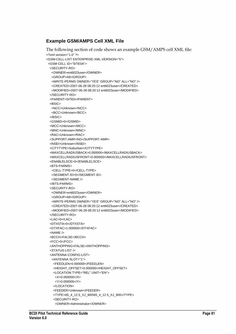
BCDI Pilot Technical Reference Guide Page 81 Version 6.0
Example GSM/AMPS Cell XML File
The following section of code shows an example GSM/AMPS cell XML file: <?xml version="1.0" ?>
<GSM-CELL-LIST ENTERPRISE-XML-VERSION="5">
<GSM-CELL ID="SITE0A">
<SECURITY-RO>
<OWNER>ent6023user</OWNER>
<GROUP>All</GROUP>
<WRITE-PERMS OWNER="YES" GROUP="NO" ALL="NO" />
<CREATED>2007-06-28 08:20:12 ent6023user</CREATED>
<MODIFIED>2007-06-28 08:20:12 ent6023user</MODIFIED>
</SECURITY-RO>
<PARENT>SITE0</PARENT>
<BSIC>
<NCC>Unknown</NCC>
<BCC>Unknown</BCC>
</BSIC>
<GSMID>0</GSMID>
<MCC>Unknown</MCC>
<MNC>Unknown</MNC>
<RAC>Unknown</RAC>
<SUPPORT-AMR>NO</SUPPORT-AMR>
<NSEI>Unknown</NSEI>
<CITYTYPE>Suburban</CITYTYPE>
<MAXCELLRADIUSBACK>0.000000</MAXCELLRADIUSBACK>
<MAXCELLRADIUSFRONT>0.000000</MAXCELLRADIUSFRONT>
<ENABLELSCE>0</ENABLELSCE>
<BTS-PARMS>
<CELL-TYPE>0</CELL-TYPE>
<SEGMENT-ID>0</SEGMENT-ID>
<SEGMENT-NAME />
</BTS-PARMS>
<SECURITY-RO>
<OWNER>ent6023user</OWNER>
<GROUP>All</GROUP>
<WRITE-PERMS OWNER="YES" GROUP="NO" ALL="NO" />
<CREATED>2007-06-28 08:20:12 ent6023user</CREATED>
<MODIFIED>2007-06-28 08:20:12 ent6023user</MODIFIED>
</SECURITY-RO>
<LAC>0</LAC>
<DTXSTA>0</DTXSTA>
<DTXFAC>1.000000</DTXFAC>
<NAME />
<BCCH>FALSE</BCCH>
<FCC>0</FCC>
<ANTHOPPING>FALSE</ANTHOPPING>
<STATUS-LIST />
<ANTENNA-CONFIG-LIST>
<ANTENNA SLOT="1">
<FEEDLEN>0.000000</FEEDLEN>
<HEIGHT_OFFSET>0.000000</HEIGHT_OFFSET>
<LOCATION TYPE="REL" UNIT="EN">
<X>0.000000</X>
<Y>0.000000</Y>
</LOCATION>
<FEEDER>Unknown</FEEDER>
<TYPE>65_4_12.5_XJ_900\65_4_12.5_XJ_900</TYPE>
<SECURITY-RO>
<OWNER>Administrator</OWNER>
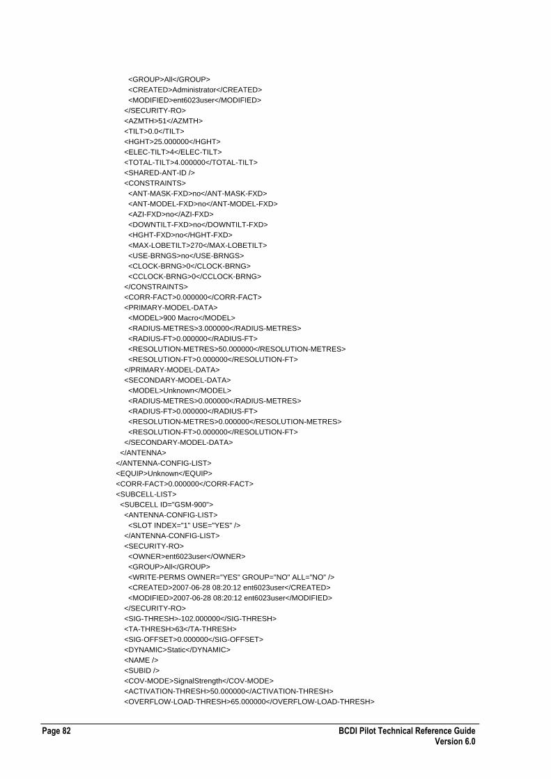
Page 82 BCDI Pilot Technical Reference Guide Version 6.0
<GROUP>All</GROUP>
<CREATED>Administrator</CREATED>
<MODIFIED>ent6023user</MODIFIED>
</SECURITY-RO>
<AZMTH>51</AZMTH>
<TILT>0.0</TILT>
<HGHT>25.000000</HGHT>
<ELEC-TILT>4</ELEC-TILT>
<TOTAL-TILT>4.000000</TOTAL-TILT>
<SHARED-ANT-ID />
<CONSTRAINTS>
<ANT-MASK-FXD>no</ANT-MASK-FXD>
<ANT-MODEL-FXD>no</ANT-MODEL-FXD>
<AZI-FXD>no</AZI-FXD>
<DOWNTILT-FXD>no</DOWNTILT-FXD>
<HGHT-FXD>no</HGHT-FXD>
<MAX-LOBETILT>270</MAX-LOBETILT>
<USE-BRNGS>no</USE-BRNGS>
<CLOCK-BRNG>0</CLOCK-BRNG>
<CCLOCK-BRNG>0</CCLOCK-BRNG>
</CONSTRAINTS>
<CORR-FACT>0.000000</CORR-FACT>
<PRIMARY-MODEL-DATA>
<MODEL>900 Macro</MODEL>
<RADIUS-METRES>3.000000</RADIUS-METRES>
<RADIUS-FT>0.000000</RADIUS-FT>
<RESOLUTION-METRES>50.000000</RESOLUTION-METRES>
<RESOLUTION-FT>0.000000</RESOLUTION-FT>
</PRIMARY-MODEL-DATA>
<SECONDARY-MODEL-DATA>
<MODEL>Unknown</MODEL>
<RADIUS-METRES>0.000000</RADIUS-METRES>
<RADIUS-FT>0.000000</RADIUS-FT>
<RESOLUTION-METRES>0.000000</RESOLUTION-METRES>
<RESOLUTION-FT>0.000000</RESOLUTION-FT>
</SECONDARY-MODEL-DATA>
</ANTENNA>
</ANTENNA-CONFIG-LIST>
<EQUIP>Unknown</EQUIP>
<CORR-FACT>0.000000</CORR-FACT>
<SUBCELL-LIST>
<SUBCELL ID="GSM-900">
<ANTENNA-CONFIG-LIST>
<SLOT INDEX="1" USE="YES" />
</ANTENNA-CONFIG-LIST>
<SECURITY-RO>
<OWNER>ent6023user</OWNER>
<GROUP>All</GROUP>
<WRITE-PERMS OWNER="YES" GROUP="NO" ALL="NO" />
<CREATED>2007-06-28 08:20:12 ent6023user</CREATED>
<MODIFIED>2007-06-28 08:20:12 ent6023user</MODIFIED>
</SECURITY-RO>
<SIG-THRESH>-102.000000</SIG-THRESH>
<TA-THRESH>63</TA-THRESH>
<SIG-OFFSET>0.000000</SIG-OFFSET>
<DYNAMIC>Static</DYNAMIC>
<NAME />
<SUBID />
<COV-MODE>SignalStrength</COV-MODE>
<ACTIVATION-THRESH>50.000000</ACTIVATION-THRESH>
<OVERFLOW-LOAD-THRESH>65.000000</OVERFLOW-LOAD-THRESH>
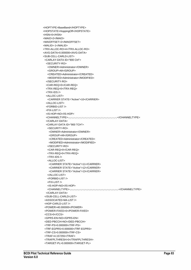
BCDI Pilot Technical Reference Guide Page 83 Version 6.0
<HOPTYPE>BaseBand</HOPTYPE>
<HOPSTATE>HoppingOff</HOPSTATE>
<HSN>0</HSN>
<MAIO>2</MAIO>
<MAIOFFSET>2</MAIOFFSET>
<MALID>-1</MALID>
<TRX-ALLOC-RO>4</TRX-ALLOC-RO>
<AVG-DATA>0.000000</AVG-DATA>
<SUB-CELL-CARLD-LIST>
<CARLAY-DATA ID="900 Ctrl">
<SECURITY-RO>
<OWNER>Administrator</OWNER>
<GROUP>All</GROUP>
<CREATED>Administrator</CREATED>
<MODIFIED>Administrator</MODIFIED>
</SECURITY-RO>
<CAR-REQ>0</CAR-REQ>
<TRX-REQ>0</TRX-REQ>
<TRX-IDS />
<ALLOC-LIST>
<CARRIER STATE="Active">10</CARRIER>
</ALLOC-LIST>
<FORBID-LIST />
<FIX-LIST />
<IS-HOP>NO</IS-HOP>
<CHANNELTYPE>-,-,-,-,-,-,-,-,-,-,-,-,-,-,-,-,-,-,-,-,-,-,-,-,-,-,-,-,-,-,-,-</CHANNELTYPE>
</CARLAY-DATA>
<CARLAY-DATA ID="900 TCH">
<SECURITY-RO>
<OWNER>Administrator</OWNER>
<GROUP>All</GROUP>
<CREATED>Administrator</CREATED>
<MODIFIED>Administrator</MODIFIED>
</SECURITY-RO>
<CAR-REQ>0</CAR-REQ>
<TRX-REQ>0</TRX-REQ>
<TRX-IDS />
<ALLOC-LIST>
<CARRIER STATE="Active">11</CARRIER>
<CARRIER STATE="Active">12</CARRIER>
<CARRIER STATE="Active">13</CARRIER>
</ALLOC-LIST>
<FORBID-LIST />
<FIX-LIST />
<IS-HOP>NO</IS-HOP>
<CHANNELTYPE>-,-,-,-,-,-,-,-,-,-,-,-,-,-,-,-,-,-,-,-,-,-,-,-,-,-,-,-,-,-,-,-</CHANNELTYPE>
</CARLAY-DATA>
</SUB-CELL-CARLD-LIST>
<ASSOCIATED-MA-LIST />
<HOP-CARLD-LIST />
<POWER>40.000000</POWER>
<POWER-FIXED>0</POWER-FIXED>
<CCS>0</CCS>
<GPRS-EN>NO</GPRS-EN>
<DED-PBCCH>NO</DED-PBCCH>
<TRF-PS>0.000000</TRF-PS>
<TRF-EGPRS>0.000000</TRF-EGPRS>
<TRF-CS>0.000000</TRF-CS>
<TRAF>4.157255</TRAF>
<TRAFPLTHRESH>0</TRAFPLTHRESH>
<TARGET-PL>0.000000</TARGET-PL>

Page 84 BCDI Pilot Technical Reference Guide Version 6.0
<AVG-DATA-EDGE>0.000000</AVG-DATA-EDGE>
<APD>0.000000</APD>
<EGPRS-MIX>0.000000</EGPRS-MIX>
<ECSD-MIX>0.000000</ECSD-MIX>
<MCS>0</MCS>
<EDGE-EN>NO</EDGE-EN>
<ECSD-EN>NO</ECSD-EN>
<BTSID>0</BTSID>
<NON-BCCH-OFFSET>0</NON-BCCH-OFFSET>
<MASTR-BTS>YES</MASTR-BTS>
</SUBCELL>
</SUBCELL-LIST>
<PRED-SYSTEM-INFO-RO>
<ANTENNA SLOT="1">
<LOCATION TYPE="ABS" UNIT="EN">
<X>562726</X>
<Y>5453767</Y>
</LOCATION>
<ANTENNA-CRC64>965571874781884770</ANTENNA-CRC64>
<SUBCELL-LIST>
<SUBCELL ID="GSM-900">
<PRIMARY-DATA>
<MODEL-CRC64>17399170414147896089</MODEL-CRC64>
<ANT-DTM-USING-MT-RES>106</ANT-DTM-USING-MT-RES>
<ANT-DTM-USING-IMP-RES>104</ANT-DTM-USING-IMP-RES>
<USE-HGHT-SMOOTHING>no</USE-HGHT-SMOOTHING>
</PRIMARY-DATA>
<SECONDARY-DATA>
<MODEL-CRC64 />
<ANT-DTM-USING-MT-RES>104</ANT-DTM-USING-MT-RES>
<ANT-DTM-USING-IMP-RES>104</ANT-DTM-USING-IMP-RES>
<USE-HGHT-SMOOTHING>no</USE-HGHT-SMOOTHING>
</SECONDARY-DATA>
</SUBCELL>
</SUBCELL-LIST>
</ANTENNA>
</PRED-SYSTEM-INFO-RO>
</GSM-CELL>
</GSM-CELL-LIST>
GSM/AMPS Repeater XML File Format
The following table describes the XML file format for GSM/AMPS repeaters:
Required Tags ID attribute
PARENT element
PROPERTY element (if importing as new)
Comments Reparenting not supported.
Relocating as for CELL-SITE.

BCDI Pilot Technical Reference Guide Page 85 Version 6.0
Enumerated Values BTS-FIXED
[YES | NO]
CALC-METHOD
[PredictRx | SpecifyRx | SpecifyTx]
ANT-MASK-FXD
[YES | NO]
ANT-MODEL-FXD
[YES | NO]
AZI-FXD
[YES | NO]
DOWNTILT-FXD
[YES | NO]
HGHT-FXD
[YES | NO]
USE-BRNGS
[YES | NO]
USE-HGHT-SMOOTHING
[YES | NO]
Example GSM/AMPS Repeater XML File
The following section of code shows an example GSM/AMPS repeater XML file: <?xml version="1.0"?>
<REPEATER-LIST ENTERPRISE-XML-VERSION="3">
<REPEATER ID="Repeater1">
<PARENT>SITE1A</PARENT>
<SECURITY-RO>
<OWNER>ent5123user</OWNER>
<GROUP>All</GROUP>
<WRITE-PERMS OWNER="YES" GROUP="NO" ALL="NO" />
<CREATED>2005-11-25 15:56:03 ent5123user</CREATED>
<MODIFIED>2005-11-25 15:56:03 ent5123user</MODIFIED>
</SECURITY-RO>
<NAME1 />
<NAME2 />
<COMMENTS />
<PROPERTY>Property40</PROPERTY>
<FREQBAND>1</FREQBAND>
<STATUS-LIST />
<CABIN>Unknown</CABIN>
<BTS>Unknown</BTS>
<MAST>Unknown</MAST>
<BTS-FIXED>NO</BTS-FIXED>
<HEX-RAD>16000.0</HEX-RAD>
<BCF-LIST />
<CALC-METHOD>PredictRx</CALC-METHOD>
<ANTENNA-RX>
<TYPE>65_4_12.5_XJ_900\65_4_12.5_XJ_900</TYPE>
<SECURITY-RO>
<OWNER>admin</OWNER>
<GROUP>All</GROUP>

Page 86 BCDI Pilot Technical Reference Guide Version 6.0
<CREATED>admin</CREATED>
<MODIFIED>admin</MODIFIED>
</SECURITY-RO>
<AZMTH>206</AZMTH>
<TILT>-1.0</TILT>
<HGHT>25.000000</HGHT>
<ELEC-TILT>4</ELEC-TILT>
<TOTAL-TILT>3.000000</TOTAL-TILT>
<SHARED-ANT-ID />
<CONSTRAINTS>
<ANT-MASK-FXD>no</ANT-MASK-FXD>
<ANT-MODEL-FXD>no</ANT-MODEL-FXD>
<AZI-FXD>no</AZI-FXD>
<DOWNTILT-FXD>no</DOWNTILT-FXD>
<HGHT-FXD>no</HGHT-FXD>
<MAX-LOBETILT>270</MAX-LOBETILT>
<USE-BRNGS>no</USE-BRNGS>
<CLOCK-BRNG>0</CLOCK-BRNG>
<CCLOCK-BRNG>0</CCLOCK-BRNG>
</CONSTRAINTS>
<RX-THRESHOLD>-120.000000</RX-THRESHOLD>
<RX-SIGNAL>0.000000</RX-SIGNAL>
</ANTENNA-RX>
<ANTENNA-TX>
<TYPE>65_4_12.5_XJ_900\65_4_12.5_XJ_900</TYPE>
<SECURITY-RO>
<OWNER>admin</OWNER>
<GROUP>All</GROUP>
<CREATED>admin</CREATED>
<MODIFIED>admin</MODIFIED>
</SECURITY-RO>
<AZMTH>0</AZMTH>
<TILT>0.0</TILT>
<HGHT>25.000000</HGHT>
<ELEC-TILT>4</ELEC-TILT>
<TOTAL-TILT>4.000000</TOTAL-TILT>
<SHARED-ANT-ID />
<CONSTRAINTS>
<ANT-MASK-FXD>no</ANT-MASK-FXD>
<ANT-MODEL-FXD>no</ANT-MODEL-FXD>
<AZI-FXD>no</AZI-FXD>
<DOWNTILT-FXD>no</DOWNTILT-FXD>
<HGHT-FXD>no</HGHT-FXD>
<MAX-LOBETILT>270</MAX-LOBETILT>
<USE-BRNGS>no</USE-BRNGS>
<CLOCK-BRNG>0</CLOCK-BRNG>
<CCLOCK-BRNG>0</CCLOCK-BRNG>
</CONSTRAINTS>
<MODEL>900 Macro</MODEL>
<GAIN>20.000000</GAIN>
<POWER>33.340000</POWER>
<PRIMARY-MODEL-DATA>
<MODEL>Unknown</MODEL>
<RADIUS-METRES>0.000000</RADIUS-METRES>
<RADIUS-FT>0.000000</RADIUS-FT>
<RESOLUTION-METRES>0.000000</RESOLUTION-METRES>
<RESOLUTION-FT>0.000000</RESOLUTION-FT>
</PRIMARY-MODEL-DATA>
<SECONDARY-MODEL-DATA>
<MODEL>Unknown</MODEL>
<RADIUS-METRES>0.000000</RADIUS-METRES>
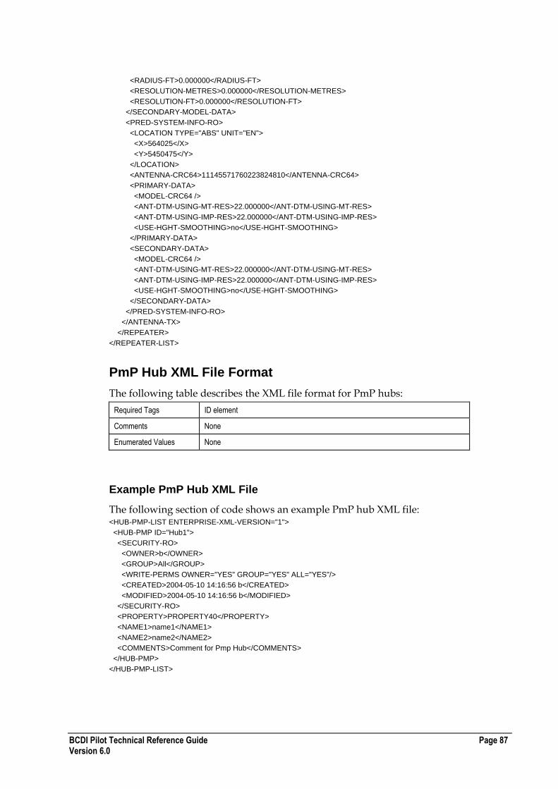
BCDI Pilot Technical Reference Guide Page 87 Version 6.0
<RADIUS-FT>0.000000</RADIUS-FT>
<RESOLUTION-METRES>0.000000</RESOLUTION-METRES>
<RESOLUTION-FT>0.000000</RESOLUTION-FT>
</SECONDARY-MODEL-DATA>
<PRED-SYSTEM-INFO-RO>
<LOCATION TYPE="ABS" UNIT="EN">
<X>564025</X>
<Y>5450475</Y>
</LOCATION>
<ANTENNA-CRC64>11145571760223824810</ANTENNA-CRC64>
<PRIMARY-DATA>
<MODEL-CRC64 />
<ANT-DTM-USING-MT-RES>22.000000</ANT-DTM-USING-MT-RES>
<ANT-DTM-USING-IMP-RES>22.000000</ANT-DTM-USING-IMP-RES>
<USE-HGHT-SMOOTHING>no</USE-HGHT-SMOOTHING>
</PRIMARY-DATA>
<SECONDARY-DATA>
<MODEL-CRC64 />
<ANT-DTM-USING-MT-RES>22.000000</ANT-DTM-USING-MT-RES>
<ANT-DTM-USING-IMP-RES>22.000000</ANT-DTM-USING-IMP-RES>
<USE-HGHT-SMOOTHING>no</USE-HGHT-SMOOTHING>
</SECONDARY-DATA>
</PRED-SYSTEM-INFO-RO>
</ANTENNA-TX>
</REPEATER>
</REPEATER-LIST>
PmP Hub XML File Format
The following table describes the XML file format for PmP hubs:
Required Tags ID element
Comments None
Enumerated Values None
Example PmP Hub XML File
The following section of code shows an example PmP hub XML file: <HUB-PMP-LIST ENTERPRISE-XML-VERSION="1">
<HUB-PMP ID="Hub1">
<SECURITY-RO>
<OWNER>b</OWNER>
<GROUP>All</GROUP>
<WRITE-PERMS OWNER="YES" GROUP="YES" ALL="YES"/>
<CREATED>2004-05-10 14:16:56 b</CREATED>
<MODIFIED>2004-05-10 14:16:56 b</MODIFIED>
</SECURITY-RO>
<PROPERTY>PROPERTY40</PROPERTY>
<NAME1>name1</NAME1>
<NAME2>name2</NAME2>
<COMMENTS>Comment for Pmp Hub</COMMENTS>
</HUB-PMP>
</HUB-PMP-LIST>

Page 88 BCDI Pilot Technical Reference Guide Version 6.0
PmP Sector XML File Format
The following table describes the XML file format for PmP sectors:
Required Tags ID attribute
PARENT attribute
Comments None
Enumerated Values None
Example PmP Sector XML File
The following section of code shows an example PmP sector XML file: <SECTOR-PMP-LIST ENTERPRISE-XML-VERSION="1">
<SECTOR-PMP ID="Hub1A" PARENT="Hub1">
<DIRECTION>0.000000</DIRECTION>
<RADIUS>1000.000000</RADIUS>
<WIDTH>60.000000</WIDTH>
<NAME1>name 1</NAME1>
<NAME2>name 2</NAME2>
<COMMENTS></COMMENTS>
<ANTENNA-LIST/>
</SECTOR-PMP>
</SECTOR-PMP-LIST>
PmP Carriers XML File Format
The following table describes the XML file format for PmP carriers:
Required Tags ID attribute
PARENT attribute
Comments None
Enumerated Values FREQ-DESIGNATION
[FD_HIGH | FD_LOW]
RADIO-SETTINGS\
MOU
[MOU_SINGLE | MOU_HOTSB | MOU_HOTSBSPACE | MOU_ONEPLUSONE1ANT | MOU_ONEPLUSONE2ANT]
RADIO-SETTINGS\
THRESH-OPT
[THRESHOPT1 | THRESHOPT2]
Example PmP Carriers XML File
The following section of code shows an example PmP carriers XML file: <?xml version="1.0" ?>
<CARRIERS-PMP-LIST ENTERPRISE-XML-VERSION="2">
<CARRIERS-PMP ID="Hub1A1" PARENT="Hub1A">
<FREQ-DIVERSITY>NO</FREQ-DIVERSITY>

BCDI Pilot Technical Reference Guide Page 89 Version 6.0
<LINK-FREQ-LIST>
<LINK-FREQ INFO="Main">
<CHANNEL-BASED>YES</CHANNEL-BASED>
<BAND>26 Ghz 7Mhz</BAND>
<CHANNEL>B01</CHANNEL>
</LINK-FREQ>
<LINK-FREQ INFO="Diversity">
<CHANNEL-BASED>NO</CHANNEL-BASED>
<BAND>Unknown</BAND>
<CHANNEL />
</LINK-FREQ>
</LINK-FREQ-LIST>
<LINKEND-FREQ-LIST>
<LINKEND-FREQ INFO="Main">
<FREQ-DESIGNATION>FD_HIGH</FREQ-DESIGNATION>
<CENTRE-FREQ>26316.000000</CENTRE-FREQ>
<FREQ-BANDWIDTH>7.000000</FREQ-BANDWIDTH>
</LINKEND-FREQ>
<LINKEND-FREQ INFO="Diversity">
<FREQ-DESIGNATION>FD_HIGH</FREQ-DESIGNATION>
<CENTRE-FREQ>38000.000000</CENTRE-FREQ>
<FREQ-BANDWIDTH>7.000000</FREQ-BANDWIDTH>
</LINKEND-FREQ>
</LINKEND-FREQ-LIST>
<RADIO-SETTINGS-LIST>
<RADIO-SETTINGS INFO="Main">
<RADIO>"FH26, 4x2"</RADIO>
<THRESH-OPT>THRESHOPT1</THRESH-OPT>
<TX-POW>18.000000</TX-POW>
<MOU>MOU_SINGLE</MOU>
<TX-BRANCH-LOSS>0.000000</TX-BRANCH-LOSS>
<RX-BRANCH-LOSS>0.000000</RX-BRANCH-LOSS>
<TX-MISC-LOSS>0.000000</TX-MISC-LOSS>
<RX-MISC-LOSS>0.000000</RX-MISC-LOSS>
<TX-ATTEN-LOSS>0.000000</TX-ATTEN-LOSS>
<RX-ATTEN-LOSS>0.000000</RX-ATTEN-LOSS>
<FEEDER-SETTINGS-LIST />
</RADIO-SETTINGS>
<RADIO-SETTINGS INFO="Diversity">
<RADIO>Unknown</RADIO>
<THRESH-OPT>THRESHOPT1</THRESH-OPT>
<TX-POW>10.000000</TX-POW>
<MOU>MOU_SINGLE</MOU>
<TX-BRANCH-LOSS>0.000000</TX-BRANCH-LOSS>
<RX-BRANCH-LOSS>0.000000</RX-BRANCH-LOSS>
<TX-MISC-LOSS>0.000000</TX-MISC-LOSS>
<RX-MISC-LOSS>0.000000</RX-MISC-LOSS>
<TX-ATTEN-LOSS>0.000000</TX-ATTEN-LOSS>
<RX-ATTEN-LOSS>0.000000</RX-ATTEN-LOSS>
<FEEDER-SETTINGS-LIST />
</RADIO-SETTINGS>
</RADIO-SETTINGS-LIST>
<NAME1 />
<NAME2 />
<COMMENTS />
<SECURITY-RO>
<OWNER>ent5123user</OWNER>
<GROUP>All</GROUP>
<WRITE-PERMS OWNER="YES" GROUP="NO" ALL="NO" />
<CREATED>2005-11-25 16:07:39 ent5123user</CREATED>
<MODIFIED>2005-11-25 16:07:39 ent5123user</MODIFIED>

Page 90 BCDI Pilot Technical Reference Guide Version 6.0
</SECURITY-RO>
</CARRIERS-PMP>
</CARRIERS-PMP-LIST>
PmP Intercon XML File Format
The following table describes the XML file format for PmP interconnects:
Required Tags ID attribute
PARENT attribute
PARENT-TYPE attribute (must agree with type of PARENT)
Comments None
Enumerated Values As per PtPIntercon
PARENT-TYPE
[HUB-LINKEND-PMP | SECTOR-PMP | CARRIERS-PMP]
Example PmP Intercon XML File
The following section of code shows an example PmP interconnect XML file: <PMP-INTERCON-LIST ENTERPRISE-XML-VERSION="1">
<PMP-INTERCON ID="PmpLink0" PARENT-TYPE="HUB-LINKEND-PMP" PARENT="Hub0">
<NAME-1>aa</NAME-1>
<NAME-2>bb</NAME-2>
<LINK-TYPE>Default Microwave</LINK-TYPE>
<LOS-REQUEST-SENT>1</LOS-REQUEST-SENT>
<LOS-STATUS>LOS</LOS-STATUS>
<COMMENTS/>
<OVERRIDE-OBS-LOSS>NO</OVERRIDE-OBS-LOSS>
<USER-DEFINED-LOSS>0.000000</USER-DEFINED-LOSS>
<DIRECT-RADIO-CAPACITY/>
<DIRECT-RADIO-FAMILY/>
<TIMESLOT-MAP-LISTS>
<TIMESLOTMAP ID="">
<SECURITY-RO>
<OWNER>AIRCOM</OWNER>
<GROUP>All</GROUP>
<CREATED> AIRCOM</CREATED>
<MODIFIED> AIRCOM</MODIFIED>
</SECURITY-RO>
<ENDA-DETAILS/>
<ENDB-DETAILS/>
<COMMENTS/>
<TIMESLOT-LIST>
<TIMESLOT>
<VALUE-64KB>-</VALUE-64KB>
<VALUE-16KB ROW="0">-</VALUE-16KB>
<VALUE-16KB ROW="1">-</VALUE-16KB>
<VALUE-16KB ROW="2">-</VALUE-16KB>
<VALUE-16KB ROW="3">-</VALUE-16KB>
<TS-DIVIDE>TSD_1ENTRY</TS-DIVIDE>
</TIMESLOT>
<!--...-->
<TIMESLOT>
<VALUE-64KB>-</VALUE-64KB>
<VALUE-16KB ROW="0">-</VALUE-16KB>

BCDI Pilot Technical Reference Guide Page 91 Version 6.0
<VALUE-16KB ROW="1">-</VALUE-16KB>
<VALUE-16KB ROW="2">-</VALUE-16KB>
<VALUE-16KB ROW="3">-</VALUE-16KB>
<TS-DIVIDE>TSD_1ENTRY</TS-DIVIDE>
</TIMESLOT>
</TIMESLOT-LIST>
</TIMESLOTMAP>
</TIMESLOT-MAP-LISTS>
<RAIN-SETTINGS>
<USE-CLIMATE-REGION>YES</USE-CLIMATE-REGION>
<CLIMATIC-REGION-ITU>A</CLIMATIC-REGION-ITU>
<CLIMATIC-REGION-CRANE>A</CLIMATIC-REGION-CRANE>
<USE-CLIMATE-REGION>0</USE-CLIMATE-REGION>
<PERCENT-EXCEED>0.010000</PERCENT-EXCEED>
<RAINRATE>0.000000</RAINRATE>
<USE-AUTOCALCULATE>NO</USE-AUTOCALCULATE>
</RAIN-SETTINGS>
<USE-SINGLE-VALUE>
<USE-SINGLE-VALUE>NO</USE-SINGLE-VALUE>
<SINGLE-VALUE>0</SINGLE-VALUE>
<PDHSDH-VALUE>STM1</PDHSDH-VALUE>
<OVERHEAD>0</OVERHEAD>
</USE-SINGLE-VALUE>
<LINK-OBJECTIVES CALC-METHOD="LOCM_821">
<GRADE>Medium</GRADE>
<CLASS>Class 2</CLASS>
<C-REF OVERRIDE="YES" UNIT="km">2.500000</C-REF>
</LINK-OBJECTIVES>
<STATUS>
<FLAG GROUP="group 1" VALUE="Field (1)"/>
</STATUS>
<CLIMATE-TERRAIN-SETTINGS>
<CALC-METHOD>CM_5310</CALC-METHOD>
<TYPE530-7>TT7_UNKNOWN</TYPE530-7>
<ALPHA>2.000000</ALPHA>
<COVER-COASTAL>NO</COVER-COASTAL>
<COASTAL-AREA>CA_INLAND</COASTAL-AREA>
<COASTAL-PROPORTION>0.000000</COASTAL-PROPORTION>
<K-FACTOR>0.000453</K-FACTOR>
<P1-VALUE>10.000000</P1-VALUE>
<CLIMATE-TERRAIN-OPTION>CTO_WATER_HUMID</CLIMATE-TERRAIN-OPTION>
<FACTOR-C>4.000000</FACTOR-C>
<ROUGHNESS>20.000000</ROUGHNESS>
<CLIMATE-FACTOR>2.000000</CLIMATE-FACTOR>
<TERRAIN-ROUGHNESS-FACTOR>1.000000</TERRAIN-ROUGHNESS-FACTOR>
<POINT-REFRACTIVITY-GRADIENT>-185.329526</POINT-REFRACTIVITY-GRADIENT>
<REGION>Global</REGION>
<PROPAGATION-EFFECT>Rain effect terrestrial</PROPAGATION-EFFECT>
<RELIABILITY-PERIOD>
<VALUE UNIT="Month">1</VALUE>
<PATH-TYPE>Hilly path</PATH-TYPE>
</RELIABILITY-PERIOD>
</CLIMATE-TERRAIN-SETTINGS>
<HUB-LINKEND-PMP>Property18::Hub0</HUB-LINKEND-PMP>
<LINKEND-PTP>Property7::PmpLink0</LINKEND-PTP>
</PMP-INTERCON>
<PMP-INTERCON>

Page 92 BCDI Pilot Technical Reference Guide Version 6.0
PmP Hub Linkend XML File Format
The following table describes the XML file format for PmP hub linkends:
Required Tags ID element
PARENT element
Comments The ID is a combination of the Property upon which the Linkend resides and the PmP Intercon for which it belongs to.
Enumerated Values None
Example PmP Hub Linkend XML File
The following section of code shows an example PmP hub linkend XML file: <HUB-LINKEND-PMP-LIST ENTERPRISE-XML-VERSION="1">
<HUB-LINKEND-PMP ID="PROPERTY40::PmpLink1" PARENT="Hub1">
<LINK-TERMINAL>Unknown</LINK-TERMINAL>
<INTF-SET>NO</INTF-SET>
<CUMULATIVE-INTF>0.000000</CUMULATIVE-INTF>
<AVG-REFRACTIVITY>300.000000</AVG-REFRACTIVITY>
<MIN-ANT-HEIGHT>0.000000</MIN-ANT-HEIGHT>
<IS-END-A>YES</IS-END-A>
<SECURITY-RO>
<OWNER>b</OWNER>
<GROUP>All</GROUP>
<WRITE-PERMS OWNER="YES" GROUP="YES" ALL="YES"/>
<CREATED>2004-05-10 14:16:58 b</CREATED>
<MODIFIED>2004-05-11 11:21:05 b</MODIFIED>
</SECURITY-RO>
</HUB-LINKEND-PMP>
</HUB-LINKEND-PMP-LIST>
PtP Intercon XML File Format
The following table describes the XML file format for PtP interconnects:
Required Tags ID attribute.
LINKEND-PTP element.
Comments If the LINK-TYPE element is omitted, the default type will be used.

BCDI Pilot Technical Reference Guide Page 93 Version 6.0
Enumerated Values
LOS-STATUS
[UNKNOWN | MAP LOS | MAP NO LOS | CONFIRMED LOS | CONFIRMED NO LOS | APPLIED | LICENSED | INSTALLED | COMMISSIONED | OK | TEMPORARY | LOS REQUESTED]
CALC-METHOD
[CM_5310 | CM_5307 | CM_VIGANTS]
TYPE530-7
[TT7_UNKNOWN | TT7_PLAINS | TT7_HILLS | TT7_MOUNTAINS]
COASTAL-AREA
[CA_INLAND | CA_LARGEBODIES | CA_MEDIUMBODIES | CA_INTERMEDIATE | CA_MANYLAKES]
CLIMATE-TERRAIN-OPTION
[CTO_WATER_HUMID | CTO_AVERAGE | CTO_MOUNTAIN | CTO_USER | CTO_CALC]
REGION
[ Global | Europe (North-West) | Europe (North-West [1.3 GHz]) | Europe (North-West [11 GHz]) | Europe (Mediterranean) | Europe (Nordic) | Europe (Alpine) | Europe (Poland) | Europe (Russia) | Europe (UK [40 and 50 GHz]) | Congo | Canada (Prairie and North) | Canada (Coast and Great Lake) | Canada (Central and Mountains) | USA (Virginia) | Australia (Temperate / Costal) | Australia (Subtropical / Costal) | Australia (Tropical / Arid) | Indonesia | Japan (Tokyo) | Japan (Yamaguchi) | Japan (Kashima) | South Korea ]
PROPAGATION-EFFECT
[Rain effect terrestrial | Rain effect slant path | Rain rate | Multipath | Trans horizon land | Trans horizon sea]
RELIABILITY-PERIOD values:
UNIT (Attribute of VALUE)
[Hour(s) | Day(s) | Week(s) | Month]
PATH-TYPE
[Relatively flat path | Hilly path | Mountainous path]
CALC-METHOD (LINK-OBJECTIVES)
[LOCM_821 | LOCM_826]
GRADE
[Access | High | Medium]
CLASS
[Class 1 | Class 2 | Class 3 | Class 4]
Example PtP Intercon XML File
The following section of code shows an example PtP interconnect XML file: <?xml version="1.0"?>
</PTP-INTERCON-LIST>
<PTP-INTERCON ID="Link1">
<NAME-1 />
<NAME-2 />
<LINK-TYPE>Microwave 4E1</LINK-TYPE>
<LOS-REQUEST-SENT />
<LOS-STATUS>UNKNOWN</LOS-STATUS>
<COMMENTS />
<OVERRIDE-OBS-LOSS>NO</OVERRIDE-OBS-LOSS>

Page 94 BCDI Pilot Technical Reference Guide Version 6.0
<USER-DEFINED-LOSS>0.000000</USER-DEFINED-LOSS>
<DIRECT-RADIO-CAPACITY />
<DIRECT-RADIO-FAMILY />
<TIMESLOT-MAP-LIST>
<TIMESLOTMAP ID="Timeslot Map1">
<SECURITY-RO>
<OWNER>admin</OWNER>
<GROUP>All</GROUP>
<CREATED>admin</CREATED>
<MODIFIED>admin</MODIFIED>
</SECURITY-RO>
<ENDA-DETAILS />
<ENDB-DETAILS />
<COMMENTS />
<TIMESLOT-LIST>
<TIMESLOT>
<VALUE-64KB>-</VALUE-64KB>
<VALUE-16KB ROW="0">-</VALUE-16KB>
<VALUE-16KB ROW="1">-</VALUE-16KB>
<VALUE-16KB ROW="2">-</VALUE-16KB>
<VALUE-16KB ROW="3">-</VALUE-16KB>
<TS-DIVIDE>TSD_1ENTRY</TS-DIVIDE>
</TIMESLOT>
<TIMESLOT>
<VALUE-64KB>-</VALUE-64KB>
<VALUE-16KB ROW="0">-</VALUE-16KB>
<VALUE-16KB ROW="1">-</VALUE-16KB>
<VALUE-16KB ROW="2">-</VALUE-16KB>
<VALUE-16KB ROW="3">-</VALUE-16KB>
<TS-DIVIDE>TSD_1ENTRY</TS-DIVIDE>
</TIMESLOT>
<TIMESLOT>
<VALUE-64KB>-</VALUE-64KB>
<VALUE-16KB ROW="0">-</VALUE-16KB>
<VALUE-16KB ROW="1">-</VALUE-16KB>
<VALUE-16KB ROW="2">-</VALUE-16KB>
<VALUE-16KB ROW="3">-</VALUE-16KB>
<TS-DIVIDE>TSD_1ENTRY</TS-DIVIDE>
</TIMESLOT>
<TIMESLOT>
<VALUE-64KB>-</VALUE-64KB>
<VALUE-16KB ROW="0">-</VALUE-16KB>
<VALUE-16KB ROW="1">-</VALUE-16KB>
<VALUE-16KB ROW="2">-</VALUE-16KB>
<VALUE-16KB ROW="3">-</VALUE-16KB>
<TS-DIVIDE>TSD_1ENTRY</TS-DIVIDE>
</TIMESLOT>
<TIMESLOT>
<VALUE-64KB>-</VALUE-64KB>
<VALUE-16KB ROW="0">-</VALUE-16KB>
<VALUE-16KB ROW="1">-</VALUE-16KB>
<VALUE-16KB ROW="2">-</VALUE-16KB>
<VALUE-16KB ROW="3">-</VALUE-16KB>
<TS-DIVIDE>TSD_1ENTRY</TS-DIVIDE>
</TIMESLOT>
<TIMESLOT>
<VALUE-64KB>-</VALUE-64KB>
<VALUE-16KB ROW="0">-</VALUE-16KB>
<VALUE-16KB ROW="1">-</VALUE-16KB>
<VALUE-16KB ROW="2">-</VALUE-16KB>
<VALUE-16KB ROW="3">-</VALUE-16KB>
BCDI Pilot Technical Reference Guide Page 95 Version 6.0
<TS-DIVIDE>TSD_1ENTRY</TS-DIVIDE>
</TIMESLOT>
<TIMESLOT>
<VALUE-64KB>-</VALUE-64KB>
<VALUE-16KB ROW="0">-</VALUE-16KB>
<VALUE-16KB ROW="1">-</VALUE-16KB>
<VALUE-16KB ROW="2">-</VALUE-16KB>
<VALUE-16KB ROW="3">-</VALUE-16KB>
<TS-DIVIDE>TSD_1ENTRY</TS-DIVIDE>
</TIMESLOT>
<TIMESLOT>
<VALUE-64KB>-</VALUE-64KB>
<VALUE-16KB ROW="0">-</VALUE-16KB>
<VALUE-16KB ROW="1">-</VALUE-16KB>
<VALUE-16KB ROW="2">-</VALUE-16KB>
<VALUE-16KB ROW="3">-</VALUE-16KB>
<TS-DIVIDE>TSD_1ENTRY</TS-DIVIDE>
</TIMESLOT>
<TIMESLOT>
<VALUE-64KB>-</VALUE-64KB>
<VALUE-16KB ROW="0">-</VALUE-16KB>
<VALUE-16KB ROW="1">-</VALUE-16KB>
<VALUE-16KB ROW="2">-</VALUE-16KB>
<VALUE-16KB ROW="3">-</VALUE-16KB>
<TS-DIVIDE>TSD_1ENTRY</TS-DIVIDE>
</TIMESLOT>
<TIMESLOT>
<VALUE-64KB>-</VALUE-64KB>
<VALUE-16KB ROW="0">-</VALUE-16KB>
<VALUE-16KB ROW="1">-</VALUE-16KB>
<VALUE-16KB ROW="2">-</VALUE-16KB>
<VALUE-16KB ROW="3">-</VALUE-16KB>
<TS-DIVIDE>TSD_1ENTRY</TS-DIVIDE>
</TIMESLOT>
<TIMESLOT>
<VALUE-64KB>-</VALUE-64KB>
<VALUE-16KB ROW="0">-</VALUE-16KB>
<VALUE-16KB ROW="1">-</VALUE-16KB>
<VALUE-16KB ROW="2">-</VALUE-16KB>
<VALUE-16KB ROW="3">-</VALUE-16KB>
<TS-DIVIDE>TSD_1ENTRY</TS-DIVIDE>
</TIMESLOT>
<TIMESLOT>
<VALUE-64KB>-</VALUE-64KB>
<VALUE-16KB ROW="0">-</VALUE-16KB>
<VALUE-16KB ROW="1">-</VALUE-16KB>
<VALUE-16KB ROW="2">-</VALUE-16KB>
<VALUE-16KB ROW="3">-</VALUE-16KB>
<TS-DIVIDE>TSD_1ENTRY</TS-DIVIDE>
</TIMESLOT>
<TIMESLOT>
<VALUE-64KB>-</VALUE-64KB>
<VALUE-16KB ROW="0">-</VALUE-16KB>
<VALUE-16KB ROW="1">-</VALUE-16KB>
<VALUE-16KB ROW="2">-</VALUE-16KB>
<VALUE-16KB ROW="3">-</VALUE-16KB>
<TS-DIVIDE>TSD_1ENTRY</TS-DIVIDE>
</TIMESLOT>
<TIMESLOT>
<VALUE-64KB>-</VALUE-64KB>
<VALUE-16KB ROW="0">-</VALUE-16KB>
Page 96 BCDI Pilot Technical Reference Guide Version 6.0
<VALUE-16KB ROW="1">-</VALUE-16KB>
<VALUE-16KB ROW="2">-</VALUE-16KB>
<VALUE-16KB ROW="3">-</VALUE-16KB>
<TS-DIVIDE>TSD_1ENTRY</TS-DIVIDE>
</TIMESLOT>
<TIMESLOT>
<VALUE-64KB>-</VALUE-64KB>
<VALUE-16KB ROW="0">-</VALUE-16KB>
<VALUE-16KB ROW="1">-</VALUE-16KB>
<VALUE-16KB ROW="2">-</VALUE-16KB>
<VALUE-16KB ROW="3">-</VALUE-16KB>
<TS-DIVIDE>TSD_1ENTRY</TS-DIVIDE>
</TIMESLOT>
<TIMESLOT>
<VALUE-64KB>-</VALUE-64KB>
<VALUE-16KB ROW="0">-</VALUE-16KB>
<VALUE-16KB ROW="1">-</VALUE-16KB>
<VALUE-16KB ROW="2">-</VALUE-16KB>
<VALUE-16KB ROW="3">-</VALUE-16KB>
<TS-DIVIDE>TSD_1ENTRY</TS-DIVIDE>
</TIMESLOT>
<TIMESLOT>
<VALUE-64KB>-</VALUE-64KB>
<VALUE-16KB ROW="0">-</VALUE-16KB>
<VALUE-16KB ROW="1">-</VALUE-16KB>
<VALUE-16KB ROW="2">-</VALUE-16KB>
<VALUE-16KB ROW="3">-</VALUE-16KB>
<TS-DIVIDE>TSD_1ENTRY</TS-DIVIDE>
</TIMESLOT>
<TIMESLOT>
<VALUE-64KB>-</VALUE-64KB>
<VALUE-16KB ROW="0">-</VALUE-16KB>
<VALUE-16KB ROW="1">-</VALUE-16KB>
<VALUE-16KB ROW="2">-</VALUE-16KB>
<VALUE-16KB ROW="3">-</VALUE-16KB>
<TS-DIVIDE>TSD_1ENTRY</TS-DIVIDE>
</TIMESLOT>
<TIMESLOT>
<VALUE-64KB>-</VALUE-64KB>
<VALUE-16KB ROW="0">-</VALUE-16KB>
<VALUE-16KB ROW="1">-</VALUE-16KB>
<VALUE-16KB ROW="2">-</VALUE-16KB>
<VALUE-16KB ROW="3">-</VALUE-16KB>
<TS-DIVIDE>TSD_1ENTRY</TS-DIVIDE>
</TIMESLOT>
<TIMESLOT>
<VALUE-64KB>-</VALUE-64KB>
<VALUE-16KB ROW="0">-</VALUE-16KB>
<VALUE-16KB ROW="1">-</VALUE-16KB>
<VALUE-16KB ROW="2">-</VALUE-16KB>
<VALUE-16KB ROW="3">-</VALUE-16KB>
<TS-DIVIDE>TSD_1ENTRY</TS-DIVIDE>
</TIMESLOT>
<TIMESLOT>
<VALUE-64KB>-</VALUE-64KB>
<VALUE-16KB ROW="0">-</VALUE-16KB>
<VALUE-16KB ROW="1">-</VALUE-16KB>
<VALUE-16KB ROW="2">-</VALUE-16KB>
<VALUE-16KB ROW="3">-</VALUE-16KB>
<TS-DIVIDE>TSD_1ENTRY</TS-DIVIDE>
</TIMESLOT>
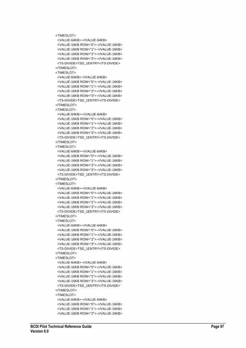
BCDI Pilot Technical Reference Guide Page 97 Version 6.0
<TIMESLOT>
<VALUE-64KB>-</VALUE-64KB>
<VALUE-16KB ROW="0">-</VALUE-16KB>
<VALUE-16KB ROW="1">-</VALUE-16KB>
<VALUE-16KB ROW="2">-</VALUE-16KB>
<VALUE-16KB ROW="3">-</VALUE-16KB>
<TS-DIVIDE>TSD_1ENTRY</TS-DIVIDE>
</TIMESLOT>
<TIMESLOT>
<VALUE-64KB>-</VALUE-64KB>
<VALUE-16KB ROW="0">-</VALUE-16KB>
<VALUE-16KB ROW="1">-</VALUE-16KB>
<VALUE-16KB ROW="2">-</VALUE-16KB>
<VALUE-16KB ROW="3">-</VALUE-16KB>
<TS-DIVIDE>TSD_1ENTRY</TS-DIVIDE>
</TIMESLOT>
<TIMESLOT>
<VALUE-64KB>-</VALUE-64KB>
<VALUE-16KB ROW="0">-</VALUE-16KB>
<VALUE-16KB ROW="1">-</VALUE-16KB>
<VALUE-16KB ROW="2">-</VALUE-16KB>
<VALUE-16KB ROW="3">-</VALUE-16KB>
<TS-DIVIDE>TSD_1ENTRY</TS-DIVIDE>
</TIMESLOT>
<TIMESLOT>
<VALUE-64KB>-</VALUE-64KB>
<VALUE-16KB ROW="0">-</VALUE-16KB>
<VALUE-16KB ROW="1">-</VALUE-16KB>
<VALUE-16KB ROW="2">-</VALUE-16KB>
<VALUE-16KB ROW="3">-</VALUE-16KB>
<TS-DIVIDE>TSD_1ENTRY</TS-DIVIDE>
</TIMESLOT>
<TIMESLOT>
<VALUE-64KB>-</VALUE-64KB>
<VALUE-16KB ROW="0">-</VALUE-16KB>
<VALUE-16KB ROW="1">-</VALUE-16KB>
<VALUE-16KB ROW="2">-</VALUE-16KB>
<VALUE-16KB ROW="3">-</VALUE-16KB>
<TS-DIVIDE>TSD_1ENTRY</TS-DIVIDE>
</TIMESLOT>
<TIMESLOT>
<VALUE-64KB>-</VALUE-64KB>
<VALUE-16KB ROW="0">-</VALUE-16KB>
<VALUE-16KB ROW="1">-</VALUE-16KB>
<VALUE-16KB ROW="2">-</VALUE-16KB>
<VALUE-16KB ROW="3">-</VALUE-16KB>
<TS-DIVIDE>TSD_1ENTRY</TS-DIVIDE>
</TIMESLOT>
<TIMESLOT>
<VALUE-64KB>-</VALUE-64KB>
<VALUE-16KB ROW="0">-</VALUE-16KB>
<VALUE-16KB ROW="1">-</VALUE-16KB>
<VALUE-16KB ROW="2">-</VALUE-16KB>
<VALUE-16KB ROW="3">-</VALUE-16KB>
<TS-DIVIDE>TSD_1ENTRY</TS-DIVIDE>
</TIMESLOT>
<TIMESLOT>
<VALUE-64KB>-</VALUE-64KB>
<VALUE-16KB ROW="0">-</VALUE-16KB>
<VALUE-16KB ROW="1">-</VALUE-16KB>
<VALUE-16KB ROW="2">-</VALUE-16KB>

Page 98 BCDI Pilot Technical Reference Guide Version 6.0
<VALUE-16KB ROW="3">-</VALUE-16KB>
<TS-DIVIDE>TSD_1ENTRY</TS-DIVIDE>
</TIMESLOT>
<TIMESLOT>
<VALUE-64KB>-</VALUE-64KB>
<VALUE-16KB ROW="0">-</VALUE-16KB>
<VALUE-16KB ROW="1">-</VALUE-16KB>
<VALUE-16KB ROW="2">-</VALUE-16KB>
<VALUE-16KB ROW="3">-</VALUE-16KB>
<TS-DIVIDE>TSD_1ENTRY</TS-DIVIDE>
</TIMESLOT>
<TIMESLOT>
<VALUE-64KB>-</VALUE-64KB>
<VALUE-16KB ROW="0">-</VALUE-16KB>
<VALUE-16KB ROW="1">-</VALUE-16KB>
<VALUE-16KB ROW="2">-</VALUE-16KB>
<VALUE-16KB ROW="3">-</VALUE-16KB>
<TS-DIVIDE>TSD_1ENTRY</TS-DIVIDE>
</TIMESLOT>
<TIMESLOT>
<VALUE-64KB>-</VALUE-64KB>
<VALUE-16KB ROW="0">-</VALUE-16KB>
<VALUE-16KB ROW="1">-</VALUE-16KB>
<VALUE-16KB ROW="2">-</VALUE-16KB>
<VALUE-16KB ROW="3">-</VALUE-16KB>
<TS-DIVIDE>TSD_1ENTRY</TS-DIVIDE>
</TIMESLOT>
</TIMESLOT-LIST>
</TIMESLOTMAP>
</TIMESLOT-MAP-LIST>
<RAIN-SETTINGS>
<USE-CLIMATE-REGION>YES</USE-CLIMATE-REGION>
<CLIMATIC-REGION-ITU>A</CLIMATIC-REGION-ITU>
<CLIMATIC-REGION-CRANE>A</CLIMATIC-REGION-CRANE>
<USE-CLIMATE-REGION>0</USE-CLIMATE-REGION>
<PERCENT-EXCEED>0.010000</PERCENT-EXCEED>
<RAINRATE>0.000000</RAINRATE>
<USE-AUTOCALCULATE>NO</USE-AUTOCALCULATE>
</RAIN-SETTINGS>
<USE-SINGLE-VALUE>
<USE-SINGLE-VALUE>NO</USE-SINGLE-VALUE>
<SINGLE-VALUE>0</SINGLE-VALUE>
<PDHSDH-VALUE>E1</PDHSDH-VALUE>
<OVERHEAD>0</OVERHEAD>
<NUMBER-OF-CHANNELS>4</NUMBER-OF-CHANNELS>
</USE-SINGLE-VALUE>
<LINK-OBJECTIVES CALC-METHOD="LOCM_826">
<GRADE>Access</GRADE>
<ERROR-PERFORMANCE>7.500000</ERROR-PERFORMANCE>
<C-REF OVERRIDE="NO" UNIT="km">0.000000</C-REF>
</LINK-OBJECTIVES>
<STATUS-LIST />
<CLIMATE-TERRAIN-SETTINGS>
<CALC-METHOD>CM_5310</CALC-METHOD>
<TYPE530-7>TT7_UNKNOWN</TYPE530-7>
<ALPHA>2.000000</ALPHA>
<COVER-COASTAL>NO</COVER-COASTAL>
<COASTAL-AREA>CA_INLAND</COASTAL-AREA>
<COASTAL-PROPORTION>0.000000</COASTAL-PROPORTION>
<K-FACTOR>0.000199</K-FACTOR>
<P1-VALUE>10.000000</P1-VALUE>

BCDI Pilot Technical Reference Guide Page 99 Version 6.0
<CLIMATE-TERRAIN-OPTION>CTO_WATER_HUMID</CLIMATE-TERRAIN-OPTION>
<FACTOR-C>4.000000</FACTOR-C>
<ROUGHNESS>20.000000</ROUGHNESS>
<CLIMATE-FACTOR>0.000199</CLIMATE-FACTOR>
<TERRAIN-ROUGHNESS-FACTOR>7.110684</TERRAIN-ROUGHNESS-FACTOR>
<POINT-REFRACTIVITY-GRADIENT>-185.819445</POINT-REFRACTIVITY-GRADIENT>
<REGION>Global</REGION>
<PROPAGATION-EFFECT>Rain effect terrestrial</PROPAGATION-EFFECT>
<RELIABILITY-PERIOD>
<VALUE UNIT="Month">1</VALUE>
<PATH-TYPE>Hilly path</PATH-TYPE>
</RELIABILITY-PERIOD>
</CLIMATE-TERRAIN-SETTINGS>
<LINKEND-PTP-LIST>
<LINKEND-PTP END="A">PROPERTY5::Link2</LINKEND-PTP>
<LINKEND-PTP END="B">Property13::Link2</LINKEND-PTP>
</LINKEND-PTP-LIST>
<LINK-FREQ-LIST>
<LINK-FREQ INFO="Main">
<CHANNEL-BASED>YES</CHANNEL-BASED>
<BAND>26 Ghz 7Mhz</BAND>
<CHANNEL>B01</CHANNEL>
</LINK-FREQ>
<LINK-FREQ INFO="Diversity">
<CHANNEL-BASED>NO</CHANNEL-BASED>
<BAND>Unknown</BAND>
<CHANNEL />
</LINK-FREQ>
</LINK-FREQ-LIST>
<FREQ-DIVERSITY>NO</FREQ-DIVERSITY>
</PTP-INTERCON>
</PTP-INTERCON-LIST>
PtP Linkend XML File Format
The following table describes the XML file format for PtP linkends:
Required Tags ID element
Comments The ID is a combination of the Property upon which the Linkend resides and the PtP Intercon for which it belongs to.
CENTRE-FREQ is in MHz
Enumerated Values
CALC-METHOD
[CM_5310 | CM_5307 | CM_VIGANTS]
Example PtP Linkend XML File
The following section of code shows an example PtP linkend XML file: <?xml version="1.0" ?>
<LINKEND-PTP-LIST ENTERPRISE-XML-VERSION="2">
<LINKEND-PTP ID="Property69::PmpLink3">
<LINK-TERMINAL>LTE1</LINK-TERMINAL>
<INTF-SET>NO</INTF-SET>
<CUMULATIVE-INTF>0.000000</CUMULATIVE-INTF>
<AVG-REFRACTIVITY>300.000000</AVG-REFRACTIVITY>
<MIN-ANT-HEIGHT>0.000000</MIN-ANT-HEIGHT>
<IS-END-A>NO</IS-END-A>
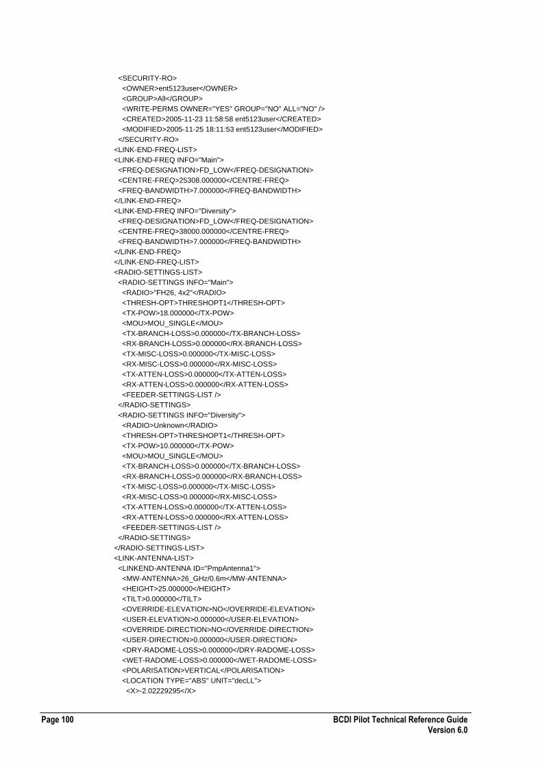
Page 100 BCDI Pilot Technical Reference Guide Version 6.0
<SECURITY-RO>
<OWNER>ent5123user</OWNER>
<GROUP>All</GROUP>
<WRITE-PERMS OWNER="YES" GROUP="NO" ALL="NO" />
<CREATED>2005-11-23 11:58:58 ent5123user</CREATED>
<MODIFIED>2005-11-25 18:11:53 ent5123user</MODIFIED>
</SECURITY-RO>
<LINK-END-FREQ-LIST>
<LINK-END-FREQ INFO="Main">
<FREQ-DESIGNATION>FD_LOW</FREQ-DESIGNATION>
<CENTRE-FREQ>25308.000000</CENTRE-FREQ>
<FREQ-BANDWIDTH>7.000000</FREQ-BANDWIDTH>
</LINK-END-FREQ>
<LINK-END-FREQ INFO="Diversity">
<FREQ-DESIGNATION>FD_LOW</FREQ-DESIGNATION>
<CENTRE-FREQ>38000.000000</CENTRE-FREQ>
<FREQ-BANDWIDTH>7.000000</FREQ-BANDWIDTH>
</LINK-END-FREQ>
</LINK-END-FREQ-LIST>
<RADIO-SETTINGS-LIST>
<RADIO-SETTINGS INFO="Main">
<RADIO>"FH26, 4x2"</RADIO>
<THRESH-OPT>THRESHOPT1</THRESH-OPT>
<TX-POW>18.000000</TX-POW>
<MOU>MOU_SINGLE</MOU>
<TX-BRANCH-LOSS>0.000000</TX-BRANCH-LOSS>
<RX-BRANCH-LOSS>0.000000</RX-BRANCH-LOSS>
<TX-MISC-LOSS>0.000000</TX-MISC-LOSS>
<RX-MISC-LOSS>0.000000</RX-MISC-LOSS>
<TX-ATTEN-LOSS>0.000000</TX-ATTEN-LOSS>
<RX-ATTEN-LOSS>0.000000</RX-ATTEN-LOSS>
<FEEDER-SETTINGS-LIST />
</RADIO-SETTINGS>
<RADIO-SETTINGS INFO="Diversity">
<RADIO>Unknown</RADIO>
<THRESH-OPT>THRESHOPT1</THRESH-OPT>
<TX-POW>10.000000</TX-POW>
<MOU>MOU_SINGLE</MOU>
<TX-BRANCH-LOSS>0.000000</TX-BRANCH-LOSS>
<RX-BRANCH-LOSS>0.000000</RX-BRANCH-LOSS>
<TX-MISC-LOSS>0.000000</TX-MISC-LOSS>
<RX-MISC-LOSS>0.000000</RX-MISC-LOSS>
<TX-ATTEN-LOSS>0.000000</TX-ATTEN-LOSS>
<RX-ATTEN-LOSS>0.000000</RX-ATTEN-LOSS>
<FEEDER-SETTINGS-LIST />
</RADIO-SETTINGS>
</RADIO-SETTINGS-LIST>
<LINK-ANTENNA-LIST>
<LINKEND-ANTENNA ID="PmpAntenna1">
<MW-ANTENNA>26_GHz/0.6m</MW-ANTENNA>
<HEIGHT>25.000000</HEIGHT>
<TILT>0.000000</TILT>
<OVERRIDE-ELEVATION>NO</OVERRIDE-ELEVATION>
<USER-ELEVATION>0.000000</USER-ELEVATION>
<OVERRIDE-DIRECTION>NO</OVERRIDE-DIRECTION>
<USER-DIRECTION>0.000000</USER-DIRECTION>
<DRY-RADOME-LOSS>0.000000</DRY-RADOME-LOSS>
<WET-RADOME-LOSS>0.000000</WET-RADOME-LOSS>
<POLARISATION>VERTICAL</POLARISATION>
<LOCATION TYPE="ABS" UNIT="decLL">
<X>-2.02229295</X>
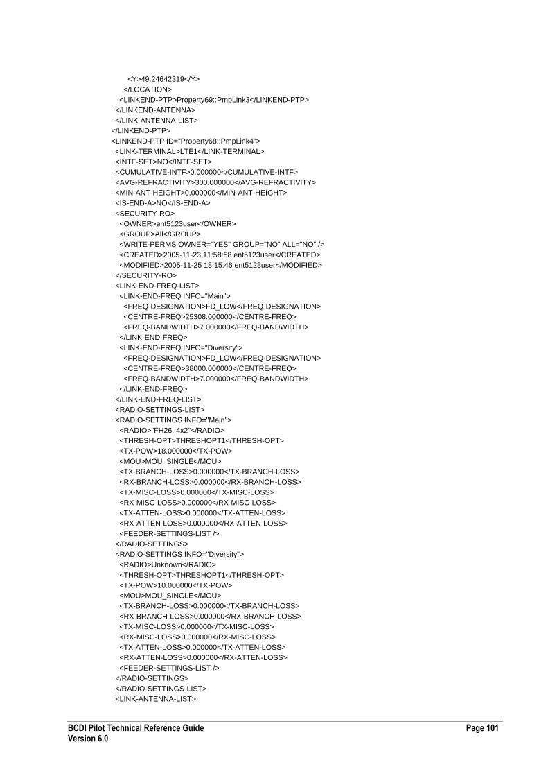
BCDI Pilot Technical Reference Guide Page 101 Version 6.0
<Y>49.24642319</Y>
</LOCATION>
<LINKEND-PTP>Property69::PmpLink3</LINKEND-PTP>
</LINKEND-ANTENNA>
</LINK-ANTENNA-LIST>
</LINKEND-PTP>
<LINKEND-PTP ID="Property68::PmpLink4">
<LINK-TERMINAL>LTE1</LINK-TERMINAL>
<INTF-SET>NO</INTF-SET>
<CUMULATIVE-INTF>0.000000</CUMULATIVE-INTF>
<AVG-REFRACTIVITY>300.000000</AVG-REFRACTIVITY>
<MIN-ANT-HEIGHT>0.000000</MIN-ANT-HEIGHT>
<IS-END-A>NO</IS-END-A>
<SECURITY-RO>
<OWNER>ent5123user</OWNER>
<GROUP>All</GROUP>
<WRITE-PERMS OWNER="YES" GROUP="NO" ALL="NO" />
<CREATED>2005-11-23 11:58:58 ent5123user</CREATED>
<MODIFIED>2005-11-25 18:15:46 ent5123user</MODIFIED>
</SECURITY-RO>
<LINK-END-FREQ-LIST>
<LINK-END-FREQ INFO="Main">
<FREQ-DESIGNATION>FD_LOW</FREQ-DESIGNATION>
<CENTRE-FREQ>25308.000000</CENTRE-FREQ>
<FREQ-BANDWIDTH>7.000000</FREQ-BANDWIDTH>
</LINK-END-FREQ>
<LINK-END-FREQ INFO="Diversity">
<FREQ-DESIGNATION>FD_LOW</FREQ-DESIGNATION>
<CENTRE-FREQ>38000.000000</CENTRE-FREQ>
<FREQ-BANDWIDTH>7.000000</FREQ-BANDWIDTH>
</LINK-END-FREQ>
</LINK-END-FREQ-LIST>
<RADIO-SETTINGS-LIST>
<RADIO-SETTINGS INFO="Main">
<RADIO>"FH26, 4x2"</RADIO>
<THRESH-OPT>THRESHOPT1</THRESH-OPT>
<TX-POW>18.000000</TX-POW>
<MOU>MOU_SINGLE</MOU>
<TX-BRANCH-LOSS>0.000000</TX-BRANCH-LOSS>
<RX-BRANCH-LOSS>0.000000</RX-BRANCH-LOSS>
<TX-MISC-LOSS>0.000000</TX-MISC-LOSS>
<RX-MISC-LOSS>0.000000</RX-MISC-LOSS>
<TX-ATTEN-LOSS>0.000000</TX-ATTEN-LOSS>
<RX-ATTEN-LOSS>0.000000</RX-ATTEN-LOSS>
<FEEDER-SETTINGS-LIST />
</RADIO-SETTINGS>
<RADIO-SETTINGS INFO="Diversity">
<RADIO>Unknown</RADIO>
<THRESH-OPT>THRESHOPT1</THRESH-OPT>
<TX-POW>10.000000</TX-POW>
<MOU>MOU_SINGLE</MOU>
<TX-BRANCH-LOSS>0.000000</TX-BRANCH-LOSS>
<RX-BRANCH-LOSS>0.000000</RX-BRANCH-LOSS>
<TX-MISC-LOSS>0.000000</TX-MISC-LOSS>
<RX-MISC-LOSS>0.000000</RX-MISC-LOSS>
<TX-ATTEN-LOSS>0.000000</TX-ATTEN-LOSS>
<RX-ATTEN-LOSS>0.000000</RX-ATTEN-LOSS>
<FEEDER-SETTINGS-LIST />
</RADIO-SETTINGS>
</RADIO-SETTINGS-LIST>
<LINK-ANTENNA-LIST>

Page 102 BCDI Pilot Technical Reference Guide Version 6.0
<LINKEND-ANTENNA ID="PmpAntenna1">
<MW-ANTENNA>26_GHz/0.6m</MW-ANTENNA>
<HEIGHT>35.000000</HEIGHT>
<TILT>0.000000</TILT>
<OVERRIDE-ELEVATION>NO</OVERRIDE-ELEVATION>
<USER-ELEVATION>0.000000</USER-ELEVATION>
<OVERRIDE-DIRECTION>NO</OVERRIDE-DIRECTION>
<USER-DIRECTION>0.000000</USER-DIRECTION>
<DRY-RADOME-LOSS>0.000000</DRY-RADOME-LOSS>
<WET-RADOME-LOSS>0.000000</WET-RADOME-LOSS>
<POLARISATION>VERTICAL</POLARISATION>
<LOCATION TYPE="ABS" UNIT="decLL">
<X>-2.01517425</X>
<Y>49.23267167</Y>
</LOCATION>
<LINKEND-PTP>Property68::PmpLink4</LINKEND-PTP>
</LINKEND-ANTENNA>
</LINK-ANTENNA-LIST>
</LINKEND-PTP>
</LINKEND-PTP-LIST>
Back To Back PrL XML File Format
The following table describes the XML file format for back to back passive repeater links.
Required Tags ID attribute
StartProperty
PassiveProperty
EndProperty
Prlinkend IsLeg1
Comments
Enumerated Values LOS-STATUS
[UNKNOWN | MAP LOS | MAP NO LOS | CONFIRMED LOS | CONFIRMED NO LOS | APPLIED | LICENSED | INSTALLED | COMMISSIONED | OK | TEMPORARY | LOS REQUESTED]
CLIMATIC-REGION-ITU
[A | B | C | D | E | F | G | H | J | K | L | M | N | P | Q]
CLIMATIC-REGION-CRANE
[A | B | B1 | B2 | C | D1 | D2 | D3 | E | F | G | H]
PDHSDHVALUE
[E0 | E1 | E2 | E3 | E4 | E5 | T1 | T2 | T3 | T4 | J1 | J2 | J3 | J4 | J5 | STM1 | STM4 | STM16 | STM64 | STM265 | STS1 | STS3 | STS9 | STS12 | STS18 | STS36 | STS48 | STS192 | STS768]
LOCATION TYPE
[ABS | REL]
UNIT
[decLL | LL | EN]
See also PmP Carrier XML File Format on page 88 and PmP Interconnect XML File Format on page 90.

BCDI Pilot Technical Reference Guide Page 103 Version 6.0
Example Back To Back PrL XML File
The following section of code shows an example Back To Back Prl XML file: <?xml version="1.0" ?>
<PRL-BACKTOBACK-LIST ENTERPRISE-XML-VERSION="2">
<PRL-BACKTOBACK ID="RepeaterBtB0">
<StartProperty>Property12</StartProperty>
<PassiveProperty>PROPERTY4</PassiveProperty>
<EndProperty>Property66</EndProperty>
<REPEATER-TYPE>Passive Repeater Link (Back to Back)</REPEATER-TYPE>
<LinkWhole ID="RepeaterBtB0">
<NAME-1 />
<NAME-2 />
<LINK-TYPE>Default Microwave</LINK-TYPE>
<LOS-REQUEST-SENT />
<LOS-STATUS>UNKNOWN</LOS-STATUS>
<COMMENTS />
<OVERRIDE-OBS-LOSS>NO</OVERRIDE-OBS-LOSS>
<USER-DEFINED-LOSS>0.000000</USER-DEFINED-LOSS>
<DIRECT-RADIO-CAPACITY />
<DIRECT-RADIO-FAMILY />
<TIMESLOT-MAP-LIST />
<RAIN-SETTINGS>
<USE-CLIMATE-REGION>YES</USE-CLIMATE-REGION>
<CLIMATIC-REGION-ITU>A</CLIMATIC-REGION-ITU>
<CLIMATIC-REGION-CRANE>A</CLIMATIC-REGION-CRANE>
<USE-CLIMATE-REGION>0</USE-CLIMATE-REGION>
<PERCENT-EXCEED>0.010000</PERCENT-EXCEED>
<RAINRATE>0.000000</RAINRATE>
<USE-AUTOCALCULATE>NO</USE-AUTOCALCULATE>
</RAIN-SETTINGS>
<USE-SINGLE-VALUE>
<USE-SINGLE-VALUE>NO</USE-SINGLE-VALUE>
<SINGLE-VALUE>0</SINGLE-VALUE>
<PDHSDH-VALUE>E1</PDHSDH-VALUE>
<OVERHEAD>0</OVERHEAD>
<NUMBER-OF-CHANNELS>2</NUMBER-OF-CHANNELS>
</USE-SINGLE-VALUE>
<LINK-OBJECTIVES CALC-METHOD="LOCM_826">
<GRADE>Access</GRADE>
<ERROR-PERFORMANCE>7.500000</ERROR-PERFORMANCE>
<C-REF OVERRIDE="NO" UNIT="km">0.000000</C-REF>
</LINK-OBJECTIVES>
<STATUS-LIST />
<CLIMATE-TERRAIN-SETTINGS>
<CALC-METHOD>CM_5310</CALC-METHOD>
<TYPE530-7>TT7_UNKNOWN</TYPE530-7>
<ALPHA>2.000000</ALPHA>
<COVER-COASTAL>NO</COVER-COASTAL>
<COASTAL-AREA>CA_INLAND</COASTAL-AREA>
<COASTAL-PROPORTION>0.000000</COASTAL-PROPORTION>
<K-FACTOR>0.000198</K-FACTOR>
<P1-VALUE>10.000000</P1-VALUE>
<CLIMATE-TERRAIN-OPTION>CTO_WATER_HUMID</CLIMATE-TERRAIN-OPTION>
<FACTOR-C>4.000000</FACTOR-C>
<ROUGHNESS>20.000000</ROUGHNESS>
<CLIMATE-FACTOR>0.000198</CLIMATE-FACTOR>
<TERRAIN-ROUGHNESS-FACTOR>7.259612</TERRAIN-ROUGHNESS-FACTOR>
<POINT-REFRACTIVITY-GRADIENT>-185.875679</POINT-REFRACTIVITY-GRADIENT>
<REGION>Global</REGION>
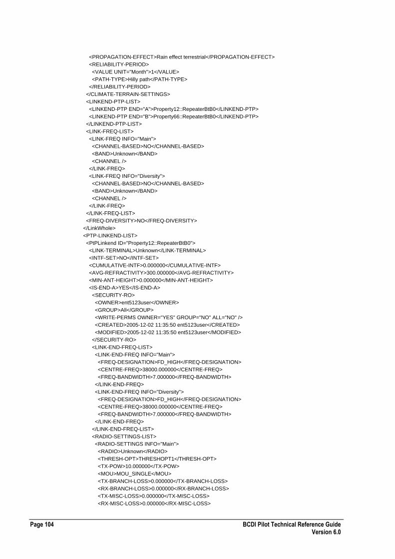
Page 104 BCDI Pilot Technical Reference Guide Version 6.0
<PROPAGATION-EFFECT>Rain effect terrestrial</PROPAGATION-EFFECT>
<RELIABILITY-PERIOD>
<VALUE UNIT="Month">1</VALUE>
<PATH-TYPE>Hilly path</PATH-TYPE>
</RELIABILITY-PERIOD>
</CLIMATE-TERRAIN-SETTINGS>
<LINKEND-PTP-LIST>
<LINKEND-PTP END="A">Property12::RepeaterBtB0</LINKEND-PTP>
<LINKEND-PTP END="B">Property66::RepeaterBtB0</LINKEND-PTP>
</LINKEND-PTP-LIST>
<LINK-FREQ-LIST>
<LINK-FREQ INFO="Main">
<CHANNEL-BASED>NO</CHANNEL-BASED>
<BAND>Unknown</BAND>
<CHANNEL />
</LINK-FREQ>
<LINK-FREQ INFO="Diversity">
<CHANNEL-BASED>NO</CHANNEL-BASED>
<BAND>Unknown</BAND>
<CHANNEL />
</LINK-FREQ>
</LINK-FREQ-LIST>
<FREQ-DIVERSITY>NO</FREQ-DIVERSITY>
</LinkWhole>
<PTP-LINKEND-LIST>
<PtPLinkend ID="Property12::RepeaterBtB0">
<LINK-TERMINAL>Unknown</LINK-TERMINAL>
<INTF-SET>NO</INTF-SET>
<CUMULATIVE-INTF>0.000000</CUMULATIVE-INTF>
<AVG-REFRACTIVITY>300.000000</AVG-REFRACTIVITY>
<MIN-ANT-HEIGHT>0.000000</MIN-ANT-HEIGHT>
<IS-END-A>YES</IS-END-A>
<SECURITY-RO>
<OWNER>ent5123user</OWNER>
<GROUP>All</GROUP>
<WRITE-PERMS OWNER="YES" GROUP="NO" ALL="NO" />
<CREATED>2005-12-02 11:35:50 ent5123user</CREATED>
<MODIFIED>2005-12-02 11:35:50 ent5123user</MODIFIED>
</SECURITY-RO>
<LINK-END-FREQ-LIST>
<LINK-END-FREQ INFO="Main">
<FREQ-DESIGNATION>FD_HIGH</FREQ-DESIGNATION>
<CENTRE-FREQ>38000.000000</CENTRE-FREQ>
<FREQ-BANDWIDTH>7.000000</FREQ-BANDWIDTH>
</LINK-END-FREQ>
<LINK-END-FREQ INFO="Diversity">
<FREQ-DESIGNATION>FD_HIGH</FREQ-DESIGNATION>
<CENTRE-FREQ>38000.000000</CENTRE-FREQ>
<FREQ-BANDWIDTH>7.000000</FREQ-BANDWIDTH>
</LINK-END-FREQ>
</LINK-END-FREQ-LIST>
<RADIO-SETTINGS-LIST>
<RADIO-SETTINGS INFO="Main">
<RADIO>Unknown</RADIO>
<THRESH-OPT>THRESHOPT1</THRESH-OPT>
<TX-POW>10.000000</TX-POW>
<MOU>MOU_SINGLE</MOU>
<TX-BRANCH-LOSS>0.000000</TX-BRANCH-LOSS>
<RX-BRANCH-LOSS>0.000000</RX-BRANCH-LOSS>
<TX-MISC-LOSS>0.000000</TX-MISC-LOSS>
<RX-MISC-LOSS>0.000000</RX-MISC-LOSS>

BCDI Pilot Technical Reference Guide Page 105 Version 6.0
<TX-ATTEN-LOSS>0.000000</TX-ATTEN-LOSS>
<RX-ATTEN-LOSS>0.000000</RX-ATTEN-LOSS>
<FEEDER-SETTINGS-LIST />
</RADIO-SETTINGS>
<RADIO-SETTINGS INFO="Diversity">
<RADIO>Unknown</RADIO>
<THRESH-OPT>THRESHOPT1</THRESH-OPT>
<TX-POW>10.000000</TX-POW>
<MOU>MOU_SINGLE</MOU>
<TX-BRANCH-LOSS>0.000000</TX-BRANCH-LOSS>
<RX-BRANCH-LOSS>0.000000</RX-BRANCH-LOSS>
<TX-MISC-LOSS>0.000000</TX-MISC-LOSS>
<RX-MISC-LOSS>0.000000</RX-MISC-LOSS>
<TX-ATTEN-LOSS>0.000000</TX-ATTEN-LOSS>
<RX-ATTEN-LOSS>0.000000</RX-ATTEN-LOSS>
<FEEDER-SETTINGS-LIST />
</RADIO-SETTINGS>
</RADIO-SETTINGS-LIST>
<LINK-ANTENNA-LIST />
</PtPLinkend>
<PtPLinkend ID="Property66::RepeaterBtB0">
<LINK-TERMINAL>Unknown</LINK-TERMINAL>
<INTF-SET>NO</INTF-SET>
<CUMULATIVE-INTF>0.000000</CUMULATIVE-INTF>
<AVG-REFRACTIVITY>300.000000</AVG-REFRACTIVITY>
<MIN-ANT-HEIGHT>0.000000</MIN-ANT-HEIGHT>
<IS-END-A>NO</IS-END-A>
<SECURITY-RO>
<OWNER>ent5123user</OWNER>
<GROUP>All</GROUP>
<WRITE-PERMS OWNER="YES" GROUP="NO" ALL="NO" />
<CREATED>2005-12-02 11:35:50 ent5123user</CREATED>
<MODIFIED>2005-12-02 11:35:50 ent5123user</MODIFIED>
</SECURITY-RO>
<LINK-END-FREQ-LIST>
<LINK-END-FREQ INFO="Main">
<FREQ-DESIGNATION>FD_LOW</FREQ-DESIGNATION>
<CENTRE-FREQ>38000.000000</CENTRE-FREQ>
<FREQ-BANDWIDTH>7.000000</FREQ-BANDWIDTH>
</LINK-END-FREQ>
<LINK-END-FREQ INFO="Diversity">
<FREQ-DESIGNATION>FD_HIGH</FREQ-DESIGNATION>
<CENTRE-FREQ>38000.000000</CENTRE-FREQ>
<FREQ-BANDWIDTH>7.000000</FREQ-BANDWIDTH>
</LINK-END-FREQ>
</LINK-END-FREQ-LIST>
<RADIO-SETTINGS-LIST>
<RADIO-SETTINGS INFO="Main">
<RADIO>Unknown</RADIO>
<THRESH-OPT>THRESHOPT1</THRESH-OPT>
<TX-POW>10.000000</TX-POW>
<MOU>MOU_SINGLE</MOU>
<TX-BRANCH-LOSS>0.000000</TX-BRANCH-LOSS>
<RX-BRANCH-LOSS>0.000000</RX-BRANCH-LOSS>
<TX-MISC-LOSS>0.000000</TX-MISC-LOSS>
<RX-MISC-LOSS>0.000000</RX-MISC-LOSS>
<TX-ATTEN-LOSS>0.000000</TX-ATTEN-LOSS>
<RX-ATTEN-LOSS>0.000000</RX-ATTEN-LOSS>
<FEEDER-SETTINGS-LIST /
</RADIO-SETTINGS>
<RADIO-SETTINGS INFO="Diversity">
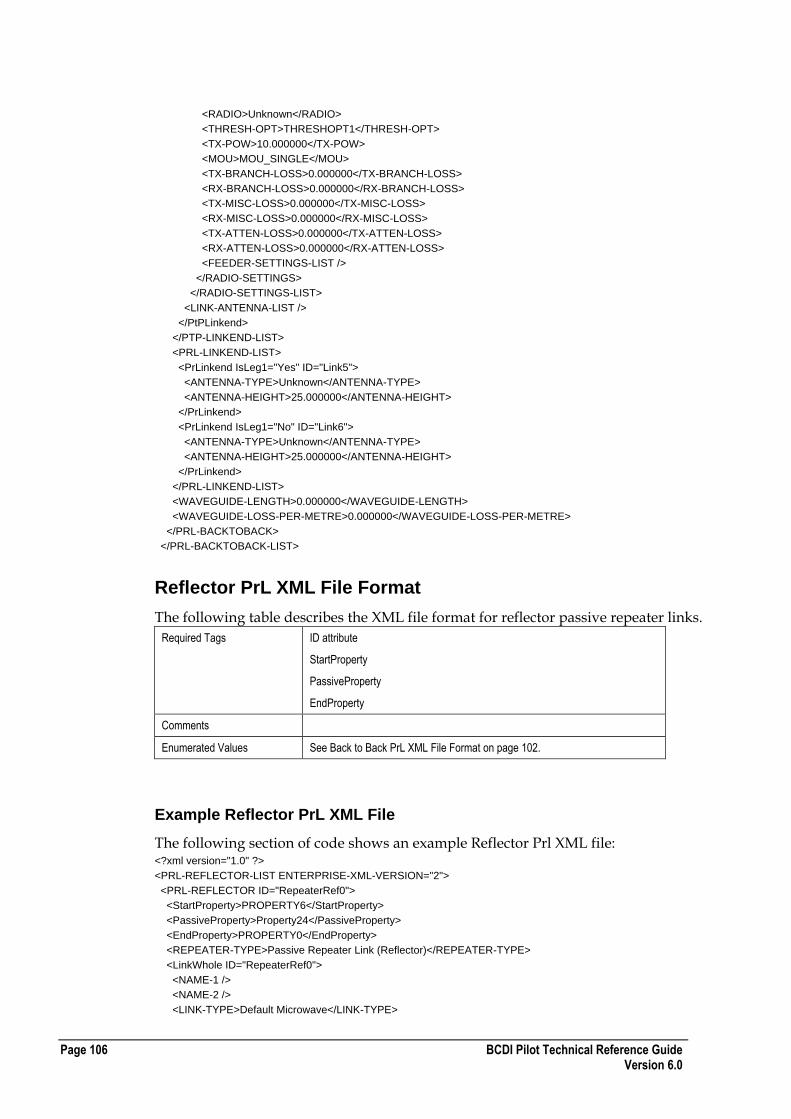
Page 106 BCDI Pilot Technical Reference Guide Version 6.0
<RADIO>Unknown</RADIO>
<THRESH-OPT>THRESHOPT1</THRESH-OPT>
<TX-POW>10.000000</TX-POW>
<MOU>MOU_SINGLE</MOU>
<TX-BRANCH-LOSS>0.000000</TX-BRANCH-LOSS>
<RX-BRANCH-LOSS>0.000000</RX-BRANCH-LOSS>
<TX-MISC-LOSS>0.000000</TX-MISC-LOSS>
<RX-MISC-LOSS>0.000000</RX-MISC-LOSS>
<TX-ATTEN-LOSS>0.000000</TX-ATTEN-LOSS>
<RX-ATTEN-LOSS>0.000000</RX-ATTEN-LOSS>
<FEEDER-SETTINGS-LIST />
</RADIO-SETTINGS>
</RADIO-SETTINGS-LIST>
<LINK-ANTENNA-LIST />
</PtPLinkend>
</PTP-LINKEND-LIST>
<PRL-LINKEND-LIST>
<PrLinkend IsLeg1="Yes" ID="Link5">
<ANTENNA-TYPE>Unknown</ANTENNA-TYPE>
<ANTENNA-HEIGHT>25.000000</ANTENNA-HEIGHT>
</PrLinkend>
<PrLinkend IsLeg1="No" ID="Link6">
<ANTENNA-TYPE>Unknown</ANTENNA-TYPE>
<ANTENNA-HEIGHT>25.000000</ANTENNA-HEIGHT>
</PrLinkend>
</PRL-LINKEND-LIST>
<WAVEGUIDE-LENGTH>0.000000</WAVEGUIDE-LENGTH>
<WAVEGUIDE-LOSS-PER-METRE>0.000000</WAVEGUIDE-LOSS-PER-METRE>
</PRL-BACKTOBACK>
</PRL-BACKTOBACK-LIST>
Reflector PrL XML File Format
The following table describes the XML file format for reflector passive repeater links.
Required Tags ID attribute
StartProperty
PassiveProperty
EndProperty
Comments
Enumerated Values See Back to Back PrL XML File Format on page 102.
Example Reflector PrL XML File
The following section of code shows an example Reflector Prl XML file: <?xml version="1.0" ?>
<PRL-REFLECTOR-LIST ENTERPRISE-XML-VERSION="2">
<PRL-REFLECTOR ID="RepeaterRef0">
<StartProperty>PROPERTY6</StartProperty>
<PassiveProperty>Property24</PassiveProperty>
<EndProperty>PROPERTY0</EndProperty>
<REPEATER-TYPE>Passive Repeater Link (Reflector)</REPEATER-TYPE>
<LinkWhole ID="RepeaterRef0">
<NAME-1 />
<NAME-2 />
<LINK-TYPE>Default Microwave</LINK-TYPE>
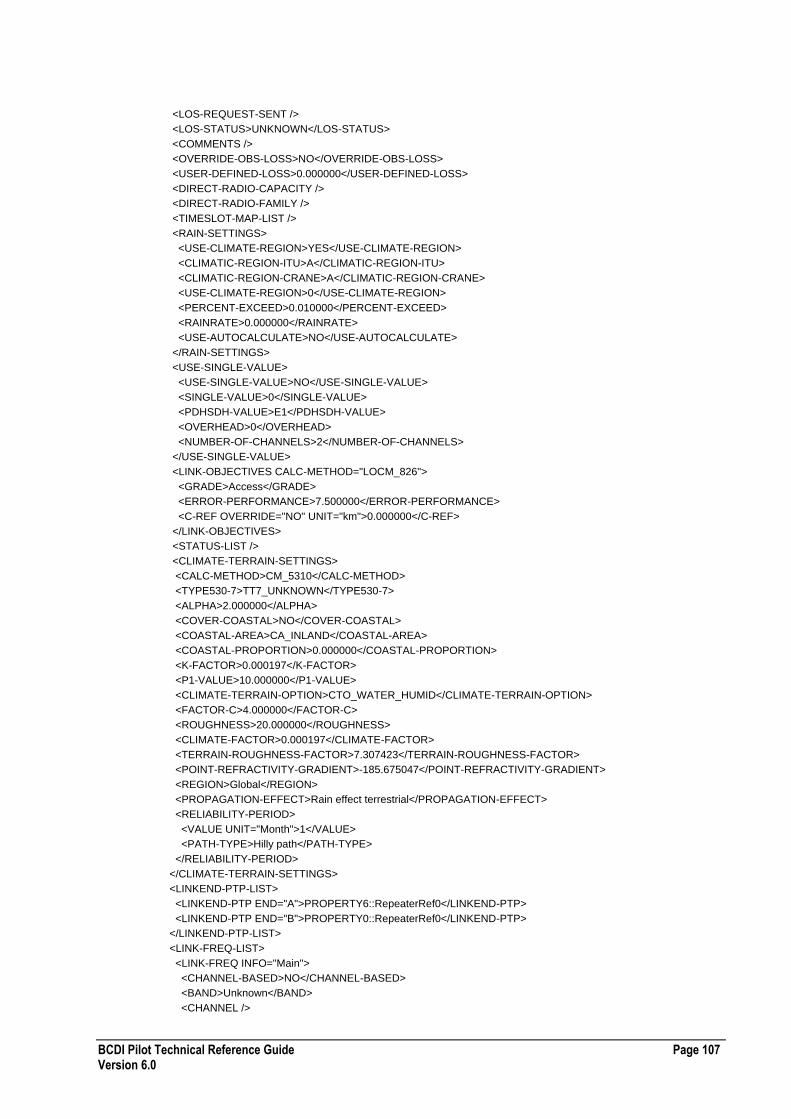
BCDI Pilot Technical Reference Guide Page 107 Version 6.0
<LOS-REQUEST-SENT />
<LOS-STATUS>UNKNOWN</LOS-STATUS>
<COMMENTS />
<OVERRIDE-OBS-LOSS>NO</OVERRIDE-OBS-LOSS>
<USER-DEFINED-LOSS>0.000000</USER-DEFINED-LOSS>
<DIRECT-RADIO-CAPACITY />
<DIRECT-RADIO-FAMILY />
<TIMESLOT-MAP-LIST />
<RAIN-SETTINGS>
<USE-CLIMATE-REGION>YES</USE-CLIMATE-REGION>
<CLIMATIC-REGION-ITU>A</CLIMATIC-REGION-ITU>
<CLIMATIC-REGION-CRANE>A</CLIMATIC-REGION-CRANE>
<USE-CLIMATE-REGION>0</USE-CLIMATE-REGION>
<PERCENT-EXCEED>0.010000</PERCENT-EXCEED>
<RAINRATE>0.000000</RAINRATE>
<USE-AUTOCALCULATE>NO</USE-AUTOCALCULATE>
</RAIN-SETTINGS>
<USE-SINGLE-VALUE>
<USE-SINGLE-VALUE>NO</USE-SINGLE-VALUE>
<SINGLE-VALUE>0</SINGLE-VALUE>
<PDHSDH-VALUE>E1</PDHSDH-VALUE>
<OVERHEAD>0</OVERHEAD>
<NUMBER-OF-CHANNELS>2</NUMBER-OF-CHANNELS>
</USE-SINGLE-VALUE>
<LINK-OBJECTIVES CALC-METHOD="LOCM_826">
<GRADE>Access</GRADE>
<ERROR-PERFORMANCE>7.500000</ERROR-PERFORMANCE>
<C-REF OVERRIDE="NO" UNIT="km">0.000000</C-REF>
</LINK-OBJECTIVES>
<STATUS-LIST />
<CLIMATE-TERRAIN-SETTINGS>
<CALC-METHOD>CM_5310</CALC-METHOD>
<TYPE530-7>TT7_UNKNOWN</TYPE530-7>
<ALPHA>2.000000</ALPHA>
<COVER-COASTAL>NO</COVER-COASTAL>
<COASTAL-AREA>CA_INLAND</COASTAL-AREA>
<COASTAL-PROPORTION>0.000000</COASTAL-PROPORTION>
<K-FACTOR>0.000197</K-FACTOR>
<P1-VALUE>10.000000</P1-VALUE>
<CLIMATE-TERRAIN-OPTION>CTO_WATER_HUMID</CLIMATE-TERRAIN-OPTION>
<FACTOR-C>4.000000</FACTOR-C>
<ROUGHNESS>20.000000</ROUGHNESS>
<CLIMATE-FACTOR>0.000197</CLIMATE-FACTOR>
<TERRAIN-ROUGHNESS-FACTOR>7.307423</TERRAIN-ROUGHNESS-FACTOR>
<POINT-REFRACTIVITY-GRADIENT>-185.675047</POINT-REFRACTIVITY-GRADIENT>
<REGION>Global</REGION>
<PROPAGATION-EFFECT>Rain effect terrestrial</PROPAGATION-EFFECT>
<RELIABILITY-PERIOD>
<VALUE UNIT="Month">1</VALUE>
<PATH-TYPE>Hilly path</PATH-TYPE>
</RELIABILITY-PERIOD>
</CLIMATE-TERRAIN-SETTINGS>
<LINKEND-PTP-LIST>
<LINKEND-PTP END="A">PROPERTY6::RepeaterRef0</LINKEND-PTP>
<LINKEND-PTP END="B">PROPERTY0::RepeaterRef0</LINKEND-PTP>
</LINKEND-PTP-LIST>
<LINK-FREQ-LIST>
<LINK-FREQ INFO="Main">
<CHANNEL-BASED>NO</CHANNEL-BASED>
<BAND>Unknown</BAND>
<CHANNEL />

Page 108 BCDI Pilot Technical Reference Guide Version 6.0
</LINK-FREQ>
<LINK-FREQ INFO="Diversity">
<CHANNEL-BASED>NO</CHANNEL-BASED>
<BAND>Unknown</BAND>
<CHANNEL />
</LINK-FREQ>
</LINK-FREQ-LIST>
<FREQ-DIVERSITY>NO</FREQ-DIVERSITY>
</LinkWhole>
<PTP-LINKEND-LIST>
<PtPLinkend ID="PROPERTY6::RepeaterRef0">
<LINK-TERMINAL>Unknown</LINK-TERMINAL>
<INTF-SET>NO</INTF-SET>
<CUMULATIVE-INTF>0.000000</CUMULATIVE-INTF>
<AVG-REFRACTIVITY>300.000000</AVG-REFRACTIVITY>
<MIN-ANT-HEIGHT>0.000000</MIN-ANT-HEIGHT>
<IS-END-A>YES</IS-END-A>
<SECURITY-RO>
<OWNER>ent5123user</OWNER>
<GROUP>All</GROUP>
<WRITE-PERMS OWNER="YES" GROUP="NO" ALL="NO" />
<CREATED>2005-12-02 11:36:14 ent5123user</CREATED>
<MODIFIED>2005-12-02 11:36:14 ent5123user</MODIFIED>
</SECURITY-RO>
<LINK-END-FREQ-LIST>
<LINK-END-FREQ INFO="Main">
<FREQ-DESIGNATION>FD_HIGH</FREQ-DESIGNATION>
<CENTRE-FREQ>38000.000000</CENTRE-FREQ>
<FREQ-BANDWIDTH>7.000000</FREQ-BANDWIDTH>
</LINK-END-FREQ>
<LINK-END-FREQ INFO="Diversity">
<FREQ-DESIGNATION>FD_HIGH</FREQ-DESIGNATION>
<CENTRE-FREQ>38000.000000</CENTRE-FREQ>
<FREQ-BANDWIDTH>7.000000</FREQ-BANDWIDTH>
</LINK-END-FREQ>
</LINK-END-FREQ-LIST>
<RADIO-SETTINGS-LIST>
<RADIO-SETTINGS INFO="Main">
<RADIO>Unknown</RADIO>
<THRESH-OPT>THRESHOPT1</THRESH-OPT>
<TX-POW>10.000000</TX-POW>
<MOU>MOU_SINGLE</MOU>
<TX-BRANCH-LOSS>0.000000</TX-BRANCH-LOSS>
<RX-BRANCH-LOSS>0.000000</RX-BRANCH-LOSS>
<TX-MISC-LOSS>0.000000</TX-MISC-LOSS>
<RX-MISC-LOSS>0.000000</RX-MISC-LOSS>
<TX-ATTEN-LOSS>0.000000</TX-ATTEN-LOSS>
<RX-ATTEN-LOSS>0.000000</RX-ATTEN-LOSS>
<FEEDER-SETTINGS-LIST />
</RADIO-SETTINGS>
<RADIO-SETTINGS INFO="Diversity">
<RADIO>Unknown</RADIO>
<THRESH-OPT>THRESHOPT1</THRESH-OPT>
<TX-POW>10.000000</TX-POW>
<MOU>MOU_SINGLE</MOU>
<TX-BRANCH-LOSS>0.000000</TX-BRANCH-LOSS>
<RX-BRANCH-LOSS>0.000000</RX-BRANCH-LOSS>
<TX-MISC-LOSS>0.000000</TX-MISC-LOSS>
<RX-MISC-LOSS>0.000000</RX-MISC-LOSS>
<TX-ATTEN-LOSS>0.000000</TX-ATTEN-LOSS>
<RX-ATTEN-LOSS>0.000000</RX-ATTEN-LOSS>

BCDI Pilot Technical Reference Guide Page 109 Version 6.0
<FEEDER-SETTINGS-LIST />
</RADIO-SETTINGS>
</RADIO-SETTINGS-LIST>
<LINK-ANTENNA-LIST />
</PtPLinkend>
<PtPLinkend ID="PROPERTY0::RepeaterRef0">
<LINK-TERMINAL>Unknown</LINK-TERMINAL>
<INTF-SET>NO</INTF-SET>
<CUMULATIVE-INTF>0.000000</CUMULATIVE-INTF>
<AVG-REFRACTIVITY>300.000000</AVG-REFRACTIVITY>
<MIN-ANT-HEIGHT>0.000000</MIN-ANT-HEIGHT>
<IS-END-A>NO</IS-END-A>
<SECURITY-RO>
<OWNER>ent5123user</OWNER>
<GROUP>All</GROUP>
<WRITE-PERMS OWNER="YES" GROUP="NO" ALL="NO" />
<CREATED>2005-12-02 11:36:14 ent5123user</CREATED>
<MODIFIED>2005-12-02 11:36:14 ent5123user</MODIFIED>
</SECURITY-RO>
<LINK-END-FREQ-LIST>
<LINK-END-FREQ INFO="Main">
<FREQ-DESIGNATION>FD_LOW</FREQ-DESIGNATION>
<CENTRE-FREQ>38000.000000</CENTRE-FREQ>
<FREQ-BANDWIDTH>7.000000</FREQ-BANDWIDTH>
</LINK-END-FREQ>
<LINK-END-FREQ INFO="Diversity">
<FREQ-DESIGNATION>FD_HIGH</FREQ-DESIGNATION>
<CENTRE-FREQ>38000.000000</CENTRE-FREQ>
<FREQ-BANDWIDTH>7.000000</FREQ-BANDWIDTH>
</LINK-END-FREQ>
</LINK-END-FREQ-LIST>
<RADIO-SETTINGS-LIST>
<RADIO-SETTINGS INFO="Main">
<RADIO>Unknown</RADIO>
<THRESH-OPT>THRESHOPT1</THRESH-OPT>
<TX-POW>10.000000</TX-POW>
<MOU>MOU_SINGLE</MOU>
<TX-BRANCH-LOSS>0.000000</TX-BRANCH-LOSS>
<RX-BRANCH-LOSS>0.000000</RX-BRANCH-LOSS>
<TX-MISC-LOSS>0.000000</TX-MISC-LOSS>
<RX-MISC-LOSS>0.000000</RX-MISC-LOSS>
<TX-ATTEN-LOSS>0.000000</TX-ATTEN-LOSS>
<RX-ATTEN-LOSS>0.000000</RX-ATTEN-LOSS>
<FEEDER-SETTINGS-LIST />
</RADIO-SETTINGS>
<RADIO-SETTINGS INFO="Diversity">
<RADIO>Unknown</RADIO>
<THRESH-OPT>THRESHOPT1</THRESH-OPT>
<TX-POW>10.000000</TX-POW>
<MOU>MOU_SINGLE</MOU>
<TX-BRANCH-LOSS>0.000000</TX-BRANCH-LOSS>
<RX-BRANCH-LOSS>0.000000</RX-BRANCH-LOSS>
<TX-MISC-LOSS>0.000000</TX-MISC-LOSS>
<RX-MISC-LOSS>0.000000</RX-MISC-LOSS>
<TX-ATTEN-LOSS>0.000000</TX-ATTEN-LOSS>
<RX-ATTEN-LOSS>0.000000</RX-ATTEN-LOSS>
<FEEDER-SETTINGS-LIST />
</RADIO-SETTINGS>
</RADIO-SETTINGS-LIST>
<LINK-ANTENNA-LIST />
</PtPLinkend>
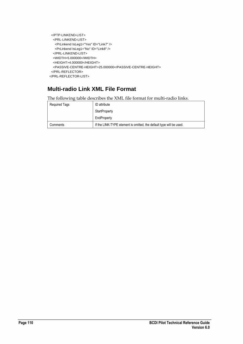
Page 110 BCDI Pilot Technical Reference Guide Version 6.0
</PTP-LINKEND-LIST>
<PRL-LINKEND-LIST>
<PrLinkend IsLeg1="Yes" ID="Link7" />
<PrLinkend IsLeg1="No" ID="Link8" />
</PRL-LINKEND-LIST>
<WIDTH>5.000000</WIDTH>
<HEIGHT>4.000000</HEIGHT>
<PASSIVE-CENTRE-HEIGHT>25.000000</PASSIVE-CENTRE-HEIGHT>
</PRL-REFLECTOR>
</PRL-REFLECTOR-LIST>
Multi-radio Link XML File Format
The following table describes the XML file format for multi-radio links.
Required Tags ID attribute
StartProperty
EndProperty
Comments If the LINK-TYPE element is omitted, the default type will be used.

BCDI Pilot Technical Reference Guide Page 111 Version 6.0
Enumerated Values LOS-STATUS
[UNKNOWN | MAP LOS | MAP NO LOS | CONFIRMED LOS | CONFIRMED NO LOS | APPLIED | LICENSED | INSTALLED | COMMISSIONED | OK | TEMPORARY | LOS REQUESTED]
OVERRIDE-OBS-LOSS
[YES|NO]
USE-CLIMATE-REGION
[YES|NO]
CLIMATIC-REGION-ITU
[A | B | C | D | E | F | G | H | J | K | L | M | N | P | Q]
CLIMATIC-REGION-CRANE
[A | B | B1 | B2 | C | D1 | D2 | D3 | E | F | G | H]
PDHSDHVALUE
[E0 | E1 | E2 | E3 | E4 | E5 | T1 | T2 | T3 | T4 | J1 | J2 | J3 | J4 | J5 | STM1 | STM4 | STM16 | STM64 | STM265 | STS1 | STS3 | STS9 | STS12 | STS18 | STS36 | STS48 | STS192 | STS768]
USE-AUTOCALCULATE
[YES|NO]
FREQ-DIVERSITY
[YES|NO]
INTF-SET
[YES|NO]
IS-END-A
[YES|NO]
USE-SINGLE-VALUE
[YES|NO]
LINK-OBJECTIVES CALC-METHOD
[LOCM_821|LOCM_826]
GRADE
[Access|Long Haul|Short Haul]
CHANNEL-BASED
[YES|NO]
POLARISATION
[VERTICAL|HORIZONTAL]
LINK-END-FREQ INFO
["Main"|"Diversity"]
FREQ-DESIGNATION
[FD_HIGH|FD_LOW]
ENABLE-ATPC
[0|1]
OVERRIDE-ATPC
[0|1]
OVERRIDE-NOM-POW
[0|1]
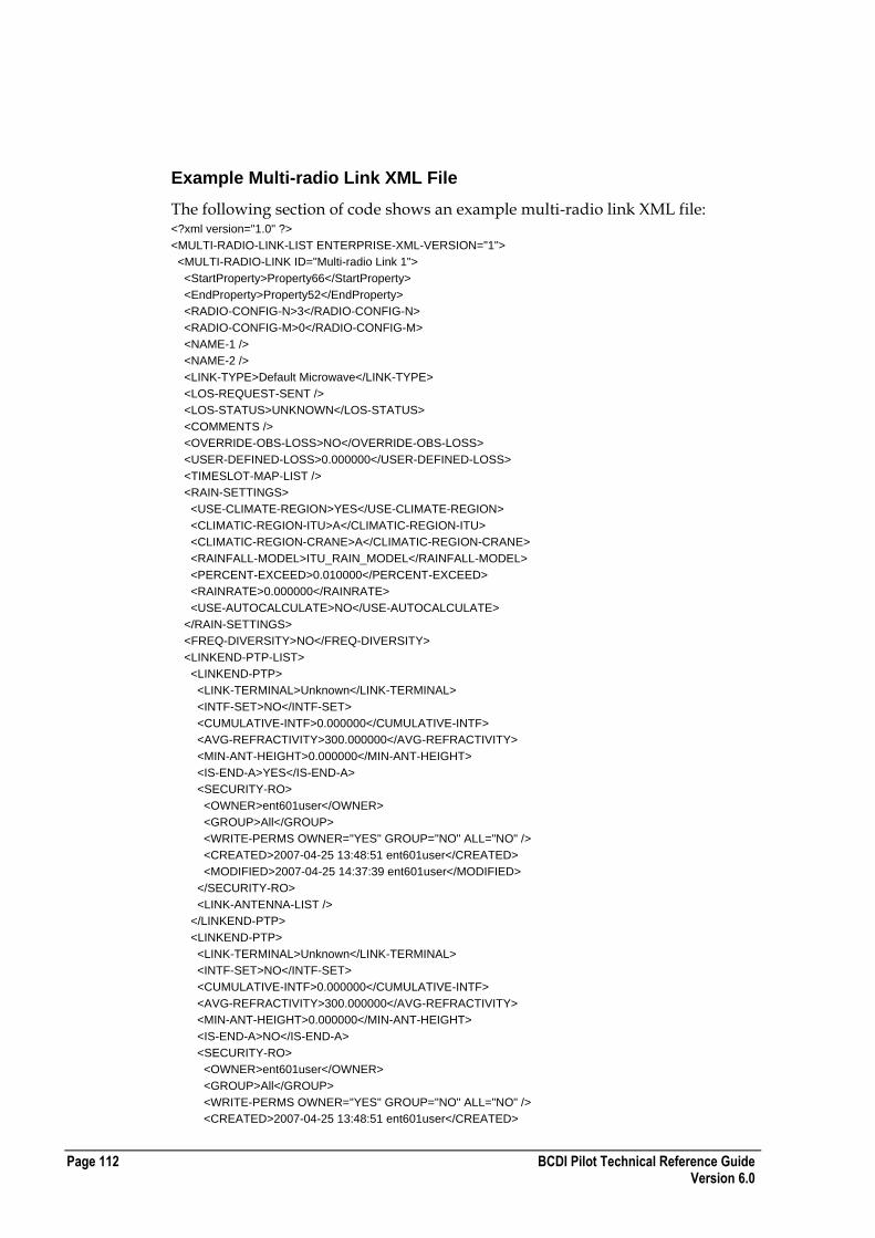
Page 112 BCDI Pilot Technical Reference Guide Version 6.0
Example Multi-radio Link XML File
The following section of code shows an example multi-radio link XML file: <?xml version="1.0" ?>
<MULTI-RADIO-LINK-LIST ENTERPRISE-XML-VERSION="1">
<MULTI-RADIO-LINK ID="Multi-radio Link 1">
<StartProperty>Property66</StartProperty>
<EndProperty>Property52</EndProperty>
<RADIO-CONFIG-N>3</RADIO-CONFIG-N>
<RADIO-CONFIG-M>0</RADIO-CONFIG-M>
<NAME-1 />
<NAME-2 />
<LINK-TYPE>Default Microwave</LINK-TYPE>
<LOS-REQUEST-SENT />
<LOS-STATUS>UNKNOWN</LOS-STATUS>
<COMMENTS />
<OVERRIDE-OBS-LOSS>NO</OVERRIDE-OBS-LOSS>
<USER-DEFINED-LOSS>0.000000</USER-DEFINED-LOSS>
<TIMESLOT-MAP-LIST />
<RAIN-SETTINGS>
<USE-CLIMATE-REGION>YES</USE-CLIMATE-REGION>
<CLIMATIC-REGION-ITU>A</CLIMATIC-REGION-ITU>
<CLIMATIC-REGION-CRANE>A</CLIMATIC-REGION-CRANE>
<RAINFALL-MODEL>ITU_RAIN_MODEL</RAINFALL-MODEL>
<PERCENT-EXCEED>0.010000</PERCENT-EXCEED>
<RAINRATE>0.000000</RAINRATE>
<USE-AUTOCALCULATE>NO</USE-AUTOCALCULATE>
</RAIN-SETTINGS>
<FREQ-DIVERSITY>NO</FREQ-DIVERSITY>
<LINKEND-PTP-LIST>
<LINKEND-PTP>
<LINK-TERMINAL>Unknown</LINK-TERMINAL>
<INTF-SET>NO</INTF-SET>
<CUMULATIVE-INTF>0.000000</CUMULATIVE-INTF>
<AVG-REFRACTIVITY>300.000000</AVG-REFRACTIVITY>
<MIN-ANT-HEIGHT>0.000000</MIN-ANT-HEIGHT>
<IS-END-A>YES</IS-END-A>
<SECURITY-RO>
<OWNER>ent601user</OWNER>
<GROUP>All</GROUP>
<WRITE-PERMS OWNER="YES" GROUP="NO" ALL="NO" />
<CREATED>2007-04-25 13:48:51 ent601user</CREATED>
<MODIFIED>2007-04-25 14:37:39 ent601user</MODIFIED>
</SECURITY-RO>
<LINK-ANTENNA-LIST />
</LINKEND-PTP>
<LINKEND-PTP>
<LINK-TERMINAL>Unknown</LINK-TERMINAL>
<INTF-SET>NO</INTF-SET>
<CUMULATIVE-INTF>0.000000</CUMULATIVE-INTF>
<AVG-REFRACTIVITY>300.000000</AVG-REFRACTIVITY>
<MIN-ANT-HEIGHT>0.000000</MIN-ANT-HEIGHT>
<IS-END-A>NO</IS-END-A>
<SECURITY-RO>
<OWNER>ent601user</OWNER>
<GROUP>All</GROUP>
<WRITE-PERMS OWNER="YES" GROUP="NO" ALL="NO" />
<CREATED>2007-04-25 13:48:51 ent601user</CREATED>
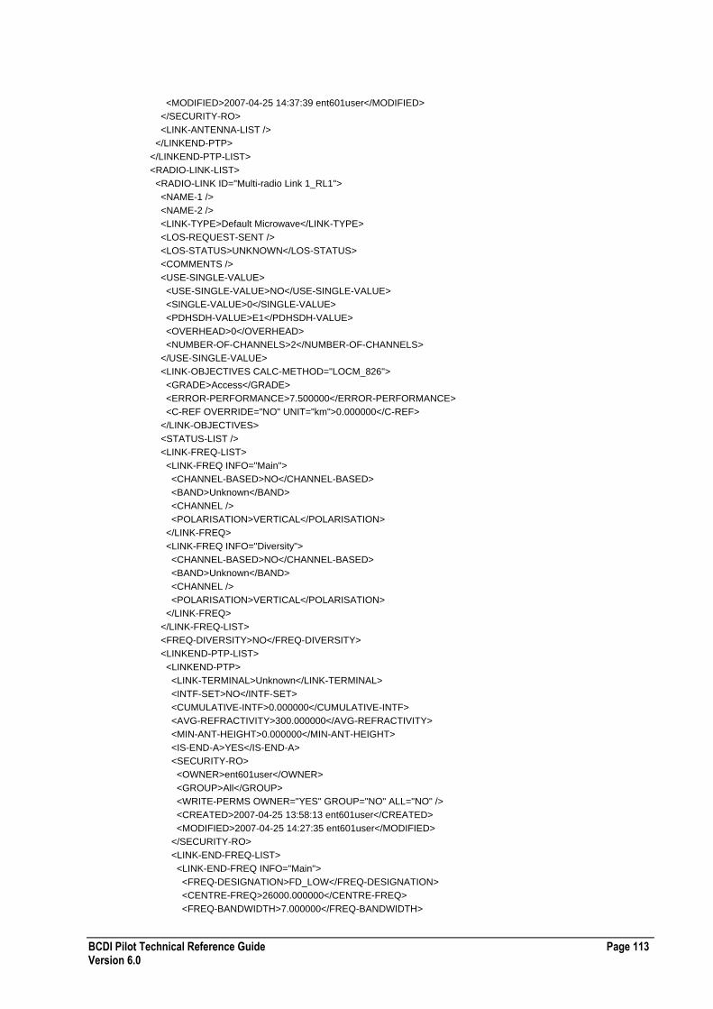
BCDI Pilot Technical Reference Guide Page 113 Version 6.0
<MODIFIED>2007-04-25 14:37:39 ent601user</MODIFIED>
</SECURITY-RO>
<LINK-ANTENNA-LIST />
</LINKEND-PTP>
</LINKEND-PTP-LIST>
<RADIO-LINK-LIST>
<RADIO-LINK ID="Multi-radio Link 1_RL1">
<NAME-1 />
<NAME-2 />
<LINK-TYPE>Default Microwave</LINK-TYPE>
<LOS-REQUEST-SENT />
<LOS-STATUS>UNKNOWN</LOS-STATUS>
<COMMENTS />
<USE-SINGLE-VALUE>
<USE-SINGLE-VALUE>NO</USE-SINGLE-VALUE>
<SINGLE-VALUE>0</SINGLE-VALUE>
<PDHSDH-VALUE>E1</PDHSDH-VALUE>
<OVERHEAD>0</OVERHEAD>
<NUMBER-OF-CHANNELS>2</NUMBER-OF-CHANNELS>
</USE-SINGLE-VALUE>
<LINK-OBJECTIVES CALC-METHOD="LOCM_826">
<GRADE>Access</GRADE>
<ERROR-PERFORMANCE>7.500000</ERROR-PERFORMANCE>
<C-REF OVERRIDE="NO" UNIT="km">0.000000</C-REF>
</LINK-OBJECTIVES>
<STATUS-LIST />
<LINK-FREQ-LIST>
<LINK-FREQ INFO="Main">
<CHANNEL-BASED>NO</CHANNEL-BASED>
<BAND>Unknown</BAND>
<CHANNEL />
<POLARISATION>VERTICAL</POLARISATION>
</LINK-FREQ>
<LINK-FREQ INFO="Diversity">
<CHANNEL-BASED>NO</CHANNEL-BASED>
<BAND>Unknown</BAND>
<CHANNEL />
<POLARISATION>VERTICAL</POLARISATION>
</LINK-FREQ>
</LINK-FREQ-LIST>
<FREQ-DIVERSITY>NO</FREQ-DIVERSITY>
<LINKEND-PTP-LIST>
<LINKEND-PTP>
<LINK-TERMINAL>Unknown</LINK-TERMINAL>
<INTF-SET>NO</INTF-SET>
<CUMULATIVE-INTF>0.000000</CUMULATIVE-INTF>
<AVG-REFRACTIVITY>300.000000</AVG-REFRACTIVITY>
<MIN-ANT-HEIGHT>0.000000</MIN-ANT-HEIGHT>
<IS-END-A>YES</IS-END-A>
<SECURITY-RO>
<OWNER>ent601user</OWNER>
<GROUP>All</GROUP>
<WRITE-PERMS OWNER="YES" GROUP="NO" ALL="NO" />
<CREATED>2007-04-25 13:58:13 ent601user</CREATED>
<MODIFIED>2007-04-25 14:27:35 ent601user</MODIFIED>
</SECURITY-RO>
<LINK-END-FREQ-LIST>
<LINK-END-FREQ INFO="Main">
<FREQ-DESIGNATION>FD_LOW</FREQ-DESIGNATION>
<CENTRE-FREQ>26000.000000</CENTRE-FREQ>
<FREQ-BANDWIDTH>7.000000</FREQ-BANDWIDTH>
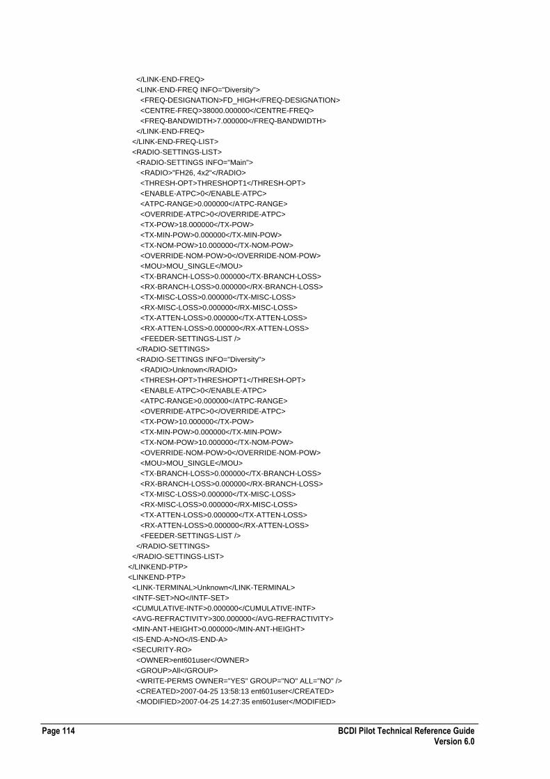
Page 114 BCDI Pilot Technical Reference Guide Version 6.0
</LINK-END-FREQ>
<LINK-END-FREQ INFO="Diversity">
<FREQ-DESIGNATION>FD_HIGH</FREQ-DESIGNATION>
<CENTRE-FREQ>38000.000000</CENTRE-FREQ>
<FREQ-BANDWIDTH>7.000000</FREQ-BANDWIDTH>
</LINK-END-FREQ>
</LINK-END-FREQ-LIST>
<RADIO-SETTINGS-LIST>
<RADIO-SETTINGS INFO="Main">
<RADIO>"FH26, 4x2"</RADIO>
<THRESH-OPT>THRESHOPT1</THRESH-OPT>
<ENABLE-ATPC>0</ENABLE-ATPC>
<ATPC-RANGE>0.000000</ATPC-RANGE>
<OVERRIDE-ATPC>0</OVERRIDE-ATPC>
<TX-POW>18.000000</TX-POW>
<TX-MIN-POW>0.000000</TX-MIN-POW>
<TX-NOM-POW>10.000000</TX-NOM-POW>
<OVERRIDE-NOM-POW>0</OVERRIDE-NOM-POW>
<MOU>MOU_SINGLE</MOU>
<TX-BRANCH-LOSS>0.000000</TX-BRANCH-LOSS>
<RX-BRANCH-LOSS>0.000000</RX-BRANCH-LOSS>
<TX-MISC-LOSS>0.000000</TX-MISC-LOSS>
<RX-MISC-LOSS>0.000000</RX-MISC-LOSS>
<TX-ATTEN-LOSS>0.000000</TX-ATTEN-LOSS>
<RX-ATTEN-LOSS>0.000000</RX-ATTEN-LOSS>
<FEEDER-SETTINGS-LIST />
</RADIO-SETTINGS>
<RADIO-SETTINGS INFO="Diversity">
<RADIO>Unknown</RADIO>
<THRESH-OPT>THRESHOPT1</THRESH-OPT>
<ENABLE-ATPC>0</ENABLE-ATPC>
<ATPC-RANGE>0.000000</ATPC-RANGE>
<OVERRIDE-ATPC>0</OVERRIDE-ATPC>
<TX-POW>10.000000</TX-POW>
<TX-MIN-POW>0.000000</TX-MIN-POW>
<TX-NOM-POW>10.000000</TX-NOM-POW>
<OVERRIDE-NOM-POW>0</OVERRIDE-NOM-POW>
<MOU>MOU_SINGLE</MOU>
<TX-BRANCH-LOSS>0.000000</TX-BRANCH-LOSS>
<RX-BRANCH-LOSS>0.000000</RX-BRANCH-LOSS>
<TX-MISC-LOSS>0.000000</TX-MISC-LOSS>
<RX-MISC-LOSS>0.000000</RX-MISC-LOSS>
<TX-ATTEN-LOSS>0.000000</TX-ATTEN-LOSS>
<RX-ATTEN-LOSS>0.000000</RX-ATTEN-LOSS>
<FEEDER-SETTINGS-LIST />
</RADIO-SETTINGS>
</RADIO-SETTINGS-LIST>
</LINKEND-PTP>
<LINKEND-PTP>
<LINK-TERMINAL>Unknown</LINK-TERMINAL>
<INTF-SET>NO</INTF-SET>
<CUMULATIVE-INTF>0.000000</CUMULATIVE-INTF>
<AVG-REFRACTIVITY>300.000000</AVG-REFRACTIVITY>
<MIN-ANT-HEIGHT>0.000000</MIN-ANT-HEIGHT>
<IS-END-A>NO</IS-END-A>
<SECURITY-RO>
<OWNER>ent601user</OWNER>
<GROUP>All</GROUP>
<WRITE-PERMS OWNER="YES" GROUP="NO" ALL="NO" />
<CREATED>2007-04-25 13:58:13 ent601user</CREATED>
<MODIFIED>2007-04-25 14:27:35 ent601user</MODIFIED>

BCDI Pilot Technical Reference Guide Page 115 Version 6.0
</SECURITY-RO>
<LINK-END-FREQ-LIST>
<LINK-END-FREQ INFO="Main">
<FREQ-DESIGNATION>FD_HIGH</FREQ-DESIGNATION>
<CENTRE-FREQ>26000.000000</CENTRE-FREQ>
<FREQ-BANDWIDTH>7.000000</FREQ-BANDWIDTH>
</LINK-END-FREQ>
<LINK-END-FREQ INFO="Diversity">
<FREQ-DESIGNATION>FD_HIGH</FREQ-DESIGNATION>
<CENTRE-FREQ>38000.000000</CENTRE-FREQ>
<FREQ-BANDWIDTH>7.000000</FREQ-BANDWIDTH>
</LINK-END-FREQ>
</LINK-END-FREQ-LIST>
<RADIO-SETTINGS-LIST>
<RADIO-SETTINGS INFO="Main">
<RADIO>"FH26, 4x2"</RADIO>
<THRESH-OPT>THRESHOPT1</THRESH-OPT>
<ENABLE-ATPC>0</ENABLE-ATPC>
<ATPC-RANGE>0.000000</ATPC-RANGE>
<OVERRIDE-ATPC>0</OVERRIDE-ATPC>
<TX-POW>18.000000</TX-POW>
<TX-MIN-POW>0.000000</TX-MIN-POW>
<TX-NOM-POW>10.000000</TX-NOM-POW>
<OVERRIDE-NOM-POW>0</OVERRIDE-NOM-POW>
<MOU>MOU_SINGLE</MOU>
<TX-BRANCH-LOSS>0.000000</TX-BRANCH-LOSS>
<RX-BRANCH-LOSS>0.000000</RX-BRANCH-LOSS>
<TX-MISC-LOSS>0.000000</TX-MISC-LOSS>
<RX-MISC-LOSS>0.000000</RX-MISC-LOSS>
<TX-ATTEN-LOSS>0.000000</TX-ATTEN-LOSS>
<RX-ATTEN-LOSS>0.000000</RX-ATTEN-LOSS>
<FEEDER-SETTINGS-LIST />
</RADIO-SETTINGS>
<RADIO-SETTINGS INFO="Diversity">
<RADIO>Unknown</RADIO>
<THRESH-OPT>THRESHOPT1</THRESH-OPT>
<ENABLE-ATPC>0</ENABLE-ATPC>
<ATPC-RANGE>0.000000</ATPC-RANGE>
<OVERRIDE-ATPC>0</OVERRIDE-ATPC>
<TX-POW>10.000000</TX-POW>
<TX-MIN-POW>0.000000</TX-MIN-POW>
<TX-NOM-POW>10.000000</TX-NOM-POW>
<OVERRIDE-NOM-POW>0</OVERRIDE-NOM-POW>
<MOU>MOU_SINGLE</MOU>
<TX-BRANCH-LOSS>0.000000</TX-BRANCH-LOSS>
<RX-BRANCH-LOSS>0.000000</RX-BRANCH-LOSS>
<TX-MISC-LOSS>0.000000</TX-MISC-LOSS>
<RX-MISC-LOSS>0.000000</RX-MISC-LOSS>
<TX-ATTEN-LOSS>0.000000</TX-ATTEN-LOSS>
<RX-ATTEN-LOSS>0.000000</RX-ATTEN-LOSS>
<FEEDER-SETTINGS-LIST />
</RADIO-SETTINGS>
</RADIO-SETTINGS-LIST>
</LINKEND-PTP>
</LINKEND-PTP-LIST>
</RADIO-LINK>
<RADIO-LINK ID="Multi-radio Link 1_RL2">
<NAME-1 />
<NAME-2 />
<LINK-TYPE>Default Microwave</LINK-TYPE>
<LOS-REQUEST-SENT />

Page 116 BCDI Pilot Technical Reference Guide Version 6.0
<LOS-STATUS>UNKNOWN</LOS-STATUS>
<COMMENTS />
<USE-SINGLE-VALUE>
<USE-SINGLE-VALUE>NO</USE-SINGLE-VALUE>
<SINGLE-VALUE>0</SINGLE-VALUE>
<PDHSDH-VALUE>E1</PDHSDH-VALUE>
<OVERHEAD>0</OVERHEAD>
<NUMBER-OF-CHANNELS>2</NUMBER-OF-CHANNELS>
</USE-SINGLE-VALUE>
<LINK-OBJECTIVES CALC-METHOD="LOCM_826">
<GRADE>Access</GRADE>
<ERROR-PERFORMANCE>7.500000</ERROR-PERFORMANCE>
<C-REF OVERRIDE="NO" UNIT="km">0.000000</C-REF>
</LINK-OBJECTIVES>
<STATUS-LIST />
<LINK-FREQ-LIST>
<LINK-FREQ INFO="Main">
<CHANNEL-BASED>NO</CHANNEL-BASED>
<BAND>Unknown</BAND>
<CHANNEL />
<POLARISATION>VERTICAL</POLARISATION>
</LINK-FREQ>
<LINK-FREQ INFO="Diversity">
<CHANNEL-BASED>NO</CHANNEL-BASED>
<BAND>Unknown</BAND>
<CHANNEL />
<POLARISATION>VERTICAL</POLARISATION>
</LINK-FREQ>
</LINK-FREQ-LIST>
<FREQ-DIVERSITY>NO</FREQ-DIVERSITY>
<LINKEND-PTP-LIST>
<LINKEND-PTP>
<LINK-TERMINAL>Unknown</LINK-TERMINAL>
<INTF-SET>NO</INTF-SET>
<CUMULATIVE-INTF>0.000000</CUMULATIVE-INTF>
<AVG-REFRACTIVITY>300.000000</AVG-REFRACTIVITY>
<MIN-ANT-HEIGHT>0.000000</MIN-ANT-HEIGHT>
<IS-END-A>YES</IS-END-A>
<SECURITY-RO>
<OWNER>ent601user</OWNER>
<GROUP>All</GROUP>
<WRITE-PERMS OWNER="YES" GROUP="NO" ALL="NO" />
<CREATED>2007-04-25 14:27:50 ent601user</CREATED>
<MODIFIED>2007-04-25 14:28:33 ent601user</MODIFIED>
</SECURITY-RO>
<LINK-END-FREQ-LIST>
<LINK-END-FREQ INFO="Main">
<FREQ-DESIGNATION>FD_LOW</FREQ-DESIGNATION>
<CENTRE-FREQ>38000.000000</CENTRE-FREQ>
<FREQ-BANDWIDTH>7.000000</FREQ-BANDWIDTH>
</LINK-END-FREQ>
<LINK-END-FREQ INFO="Diversity">
<FREQ-DESIGNATION>FD_HIGH</FREQ-DESIGNATION>
<CENTRE-FREQ>38000.000000</CENTRE-FREQ>
<FREQ-BANDWIDTH>7.000000</FREQ-BANDWIDTH>
</LINK-END-FREQ>
</LINK-END-FREQ-LIST>
<RADIO-SETTINGS-LIST>
<RADIO-SETTINGS INFO="Main">
<RADIO>"FH38, 4x2"</RADIO>
<THRESH-OPT>THRESHOPT1</THRESH-OPT>

BCDI Pilot Technical Reference Guide Page 117 Version 6.0
<ENABLE-ATPC>0</ENABLE-ATPC>
<ATPC-RANGE>0.000000</ATPC-RANGE>
<OVERRIDE-ATPC>0</OVERRIDE-ATPC>
<TX-POW>16.000000</TX-POW>
<TX-MIN-POW>0.000000</TX-MIN-POW>
<TX-NOM-POW>10.000000</TX-NOM-POW>
<OVERRIDE-NOM-POW>0</OVERRIDE-NOM-POW>
<MOU>MOU_SINGLE</MOU>
<TX-BRANCH-LOSS>0.000000</TX-BRANCH-LOSS>
<RX-BRANCH-LOSS>0.000000</RX-BRANCH-LOSS>
<TX-MISC-LOSS>0.000000</TX-MISC-LOSS>
<RX-MISC-LOSS>0.000000</RX-MISC-LOSS>
<TX-ATTEN-LOSS>0.000000</TX-ATTEN-LOSS>
<RX-ATTEN-LOSS>0.000000</RX-ATTEN-LOSS>
<FEEDER-SETTINGS-LIST />
</RADIO-SETTINGS>
<RADIO-SETTINGS INFO="Diversity">
<RADIO>Unknown</RADIO>
<THRESH-OPT>THRESHOPT1</THRESH-OPT>
<ENABLE-ATPC>0</ENABLE-ATPC>
<ATPC-RANGE>0.000000</ATPC-RANGE>
<OVERRIDE-ATPC>0</OVERRIDE-ATPC>
<TX-POW>10.000000</TX-POW>
<TX-MIN-POW>0.000000</TX-MIN-POW>
<TX-NOM-POW>10.000000</TX-NOM-POW>
<OVERRIDE-NOM-POW>0</OVERRIDE-NOM-POW>
<MOU>MOU_SINGLE</MOU>
<TX-BRANCH-LOSS>0.000000</TX-BRANCH-LOSS>
<RX-BRANCH-LOSS>0.000000</RX-BRANCH-LOSS>
<TX-MISC-LOSS>0.000000</TX-MISC-LOSS>
<RX-MISC-LOSS>0.000000</RX-MISC-LOSS>
<TX-ATTEN-LOSS>0.000000</TX-ATTEN-LOSS>
<RX-ATTEN-LOSS>0.000000</RX-ATTEN-LOSS>
<FEEDER-SETTINGS-LIST />
</RADIO-SETTINGS>
</RADIO-SETTINGS-LIST>
</LINKEND-PTP>
<LINKEND-PTP>
<LINK-TERMINAL>Unknown</LINK-TERMINAL>
<INTF-SET>NO</INTF-SET>
<CUMULATIVE-INTF>0.000000</CUMULATIVE-INTF>
<AVG-REFRACTIVITY>300.000000</AVG-REFRACTIVITY>
<MIN-ANT-HEIGHT>0.000000</MIN-ANT-HEIGHT>
<IS-END-A>NO</IS-END-A>
<SECURITY-RO>
<OWNER>ent601user</OWNER>
<GROUP>All</GROUP>
<WRITE-PERMS OWNER="YES" GROUP="NO" ALL="NO" />
<CREATED>2007-04-25 14:27:50 ent601user</CREATED>
<MODIFIED>2007-04-25 14:28:33 ent601user</MODIFIED>
</SECURITY-RO>
<LINK-END-FREQ-LIST>
<LINK-END-FREQ INFO="Main">
<FREQ-DESIGNATION>FD_HIGH</FREQ-DESIGNATION>
<CENTRE-FREQ>38000.000000</CENTRE-FREQ>
<FREQ-BANDWIDTH>7.000000</FREQ-BANDWIDTH>
</LINK-END-FREQ>
<LINK-END-FREQ INFO="Diversity">
<FREQ-DESIGNATION>FD_HIGH</FREQ-DESIGNATION>
<CENTRE-FREQ>38000.000000</CENTRE-FREQ>
<FREQ-BANDWIDTH>7.000000</FREQ-BANDWIDTH>

Page 118 BCDI Pilot Technical Reference Guide Version 6.0
</LINK-END-FREQ>
</LINK-END-FREQ-LIST>
<RADIO-SETTINGS-LIST>
<RADIO-SETTINGS INFO="Main">
<RADIO>"FH38, 4x2"</RADIO>
<THRESH-OPT>THRESHOPT1</THRESH-OPT>
<ENABLE-ATPC>0</ENABLE-ATPC>
<ATPC-RANGE>0.000000</ATPC-RANGE>
<OVERRIDE-ATPC>0</OVERRIDE-ATPC>
<TX-POW>16.000000</TX-POW>
<TX-MIN-POW>0.000000</TX-MIN-POW>
<TX-NOM-POW>10.000000</TX-NOM-POW>
<OVERRIDE-NOM-POW>0</OVERRIDE-NOM-POW>
<MOU>MOU_SINGLE</MOU>
<TX-BRANCH-LOSS>0.000000</TX-BRANCH-LOSS>
<RX-BRANCH-LOSS>0.000000</RX-BRANCH-LOSS>
<TX-MISC-LOSS>0.000000</TX-MISC-LOSS>
<RX-MISC-LOSS>0.000000</RX-MISC-LOSS>
<TX-ATTEN-LOSS>0.000000</TX-ATTEN-LOSS>
<RX-ATTEN-LOSS>0.000000</RX-ATTEN-LOSS>
<FEEDER-SETTINGS-LIST />
</RADIO-SETTINGS>
<RADIO-SETTINGS INFO="Diversity">
<RADIO>Unknown</RADIO>
<THRESH-OPT>THRESHOPT1</THRESH-OPT>
<ENABLE-ATPC>0</ENABLE-ATPC>
<ATPC-RANGE>0.000000</ATPC-RANGE>
<OVERRIDE-ATPC>0</OVERRIDE-ATPC>
<TX-POW>10.000000</TX-POW>
<TX-MIN-POW>0.000000</TX-MIN-POW>
<TX-NOM-POW>10.000000</TX-NOM-POW>
<OVERRIDE-NOM-POW>0</OVERRIDE-NOM-POW>
<MOU>MOU_SINGLE</MOU>
<TX-BRANCH-LOSS>0.000000</TX-BRANCH-LOSS>
<RX-BRANCH-LOSS>0.000000</RX-BRANCH-LOSS>
<TX-MISC-LOSS>0.000000</TX-MISC-LOSS>
<RX-MISC-LOSS>0.000000</RX-MISC-LOSS>
<TX-ATTEN-LOSS>0.000000</TX-ATTEN-LOSS>
<RX-ATTEN-LOSS>0.000000</RX-ATTEN-LOSS>
<FEEDER-SETTINGS-LIST />
</RADIO-SETTINGS>
</RADIO-SETTINGS-LIST>
</LINKEND-PTP>
</LINKEND-PTP-LIST>
</RADIO-LINK>
</RADIO-LINK-LIST>
</MULTI-RADIO-LINK>
</MULTI-RADIO-LINK-LIST>
Dual Polar Link XML File Format
The following table describes the XML file format for dual polar links.
Required Tags ID attribute
StartProperty
EndProperty
Comments If the LINK-TYPE element is omitted, the default type will be used.
The POLARISATION value should be different for each linkend.
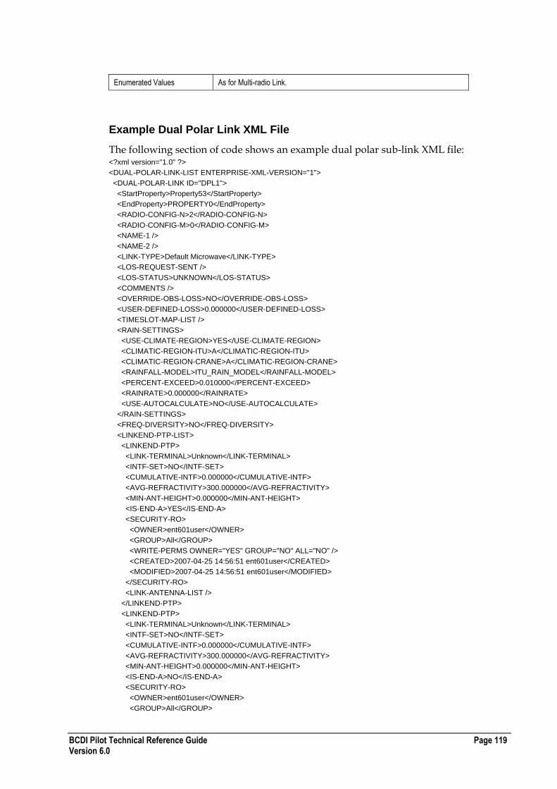
BCDI Pilot Technical Reference Guide Page 119 Version 6.0
Enumerated Values As for Multi-radio Link.
Example Dual Polar Link XML File
The following section of code shows an example dual polar sub-link XML file: <?xml version="1.0" ?>
<DUAL-POLAR-LINK-LIST ENTERPRISE-XML-VERSION="1">
<DUAL-POLAR-LINK ID="DPL1">
<StartProperty>Property53</StartProperty>
<EndProperty>PROPERTY0</EndProperty>
<RADIO-CONFIG-N>2</RADIO-CONFIG-N>
<RADIO-CONFIG-M>0</RADIO-CONFIG-M>
<NAME-1 />
<NAME-2 />
<LINK-TYPE>Default Microwave</LINK-TYPE>
<LOS-REQUEST-SENT />
<LOS-STATUS>UNKNOWN</LOS-STATUS>
<COMMENTS />
<OVERRIDE-OBS-LOSS>NO</OVERRIDE-OBS-LOSS>
<USER-DEFINED-LOSS>0.000000</USER-DEFINED-LOSS>
<TIMESLOT-MAP-LIST />
<RAIN-SETTINGS>
<USE-CLIMATE-REGION>YES</USE-CLIMATE-REGION>
<CLIMATIC-REGION-ITU>A</CLIMATIC-REGION-ITU>
<CLIMATIC-REGION-CRANE>A</CLIMATIC-REGION-CRANE>
<RAINFALL-MODEL>ITU_RAIN_MODEL</RAINFALL-MODEL>
<PERCENT-EXCEED>0.010000</PERCENT-EXCEED>
<RAINRATE>0.000000</RAINRATE>
<USE-AUTOCALCULATE>NO</USE-AUTOCALCULATE>
</RAIN-SETTINGS>
<FREQ-DIVERSITY>NO</FREQ-DIVERSITY>
<LINKEND-PTP-LIST>
<LINKEND-PTP>
<LINK-TERMINAL>Unknown</LINK-TERMINAL>
<INTF-SET>NO</INTF-SET>
<CUMULATIVE-INTF>0.000000</CUMULATIVE-INTF>
<AVG-REFRACTIVITY>300.000000</AVG-REFRACTIVITY>
<MIN-ANT-HEIGHT>0.000000</MIN-ANT-HEIGHT>
<IS-END-A>YES</IS-END-A>
<SECURITY-RO>
<OWNER>ent601user</OWNER>
<GROUP>All</GROUP>
<WRITE-PERMS OWNER="YES" GROUP="NO" ALL="NO" />
<CREATED>2007-04-25 14:56:51 ent601user</CREATED>
<MODIFIED>2007-04-25 14:56:51 ent601user</MODIFIED>
</SECURITY-RO>
<LINK-ANTENNA-LIST />
</LINKEND-PTP>
<LINKEND-PTP>
<LINK-TERMINAL>Unknown</LINK-TERMINAL>
<INTF-SET>NO</INTF-SET>
<CUMULATIVE-INTF>0.000000</CUMULATIVE-INTF>
<AVG-REFRACTIVITY>300.000000</AVG-REFRACTIVITY>
<MIN-ANT-HEIGHT>0.000000</MIN-ANT-HEIGHT>
<IS-END-A>NO</IS-END-A>
<SECURITY-RO>
<OWNER>ent601user</OWNER>
<GROUP>All</GROUP>
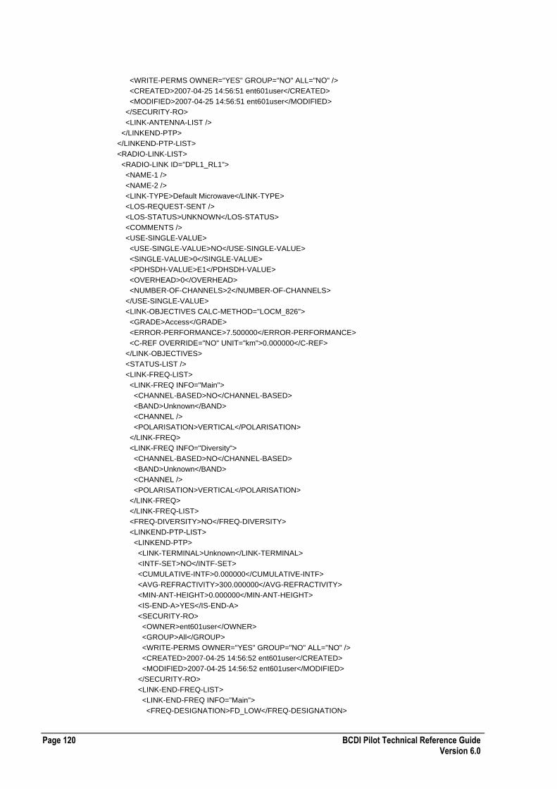
Page 120 BCDI Pilot Technical Reference Guide Version 6.0
<WRITE-PERMS OWNER="YES" GROUP="NO" ALL="NO" />
<CREATED>2007-04-25 14:56:51 ent601user</CREATED>
<MODIFIED>2007-04-25 14:56:51 ent601user</MODIFIED>
</SECURITY-RO>
<LINK-ANTENNA-LIST />
</LINKEND-PTP>
</LINKEND-PTP-LIST>
<RADIO-LINK-LIST>
<RADIO-LINK ID="DPL1_RL1">
<NAME-1 />
<NAME-2 />
<LINK-TYPE>Default Microwave</LINK-TYPE>
<LOS-REQUEST-SENT />
<LOS-STATUS>UNKNOWN</LOS-STATUS>
<COMMENTS />
<USE-SINGLE-VALUE>
<USE-SINGLE-VALUE>NO</USE-SINGLE-VALUE>
<SINGLE-VALUE>0</SINGLE-VALUE>
<PDHSDH-VALUE>E1</PDHSDH-VALUE>
<OVERHEAD>0</OVERHEAD>
<NUMBER-OF-CHANNELS>2</NUMBER-OF-CHANNELS>
</USE-SINGLE-VALUE>
<LINK-OBJECTIVES CALC-METHOD="LOCM_826">
<GRADE>Access</GRADE>
<ERROR-PERFORMANCE>7.500000</ERROR-PERFORMANCE>
<C-REF OVERRIDE="NO" UNIT="km">0.000000</C-REF>
</LINK-OBJECTIVES>
<STATUS-LIST />
<LINK-FREQ-LIST>
<LINK-FREQ INFO="Main">
<CHANNEL-BASED>NO</CHANNEL-BASED>
<BAND>Unknown</BAND>
<CHANNEL />
<POLARISATION>VERTICAL</POLARISATION>
</LINK-FREQ>
<LINK-FREQ INFO="Diversity">
<CHANNEL-BASED>NO</CHANNEL-BASED>
<BAND>Unknown</BAND>
<CHANNEL />
<POLARISATION>VERTICAL</POLARISATION>
</LINK-FREQ>
</LINK-FREQ-LIST>
<FREQ-DIVERSITY>NO</FREQ-DIVERSITY>
<LINKEND-PTP-LIST>
<LINKEND-PTP>
<LINK-TERMINAL>Unknown</LINK-TERMINAL>
<INTF-SET>NO</INTF-SET>
<CUMULATIVE-INTF>0.000000</CUMULATIVE-INTF>
<AVG-REFRACTIVITY>300.000000</AVG-REFRACTIVITY>
<MIN-ANT-HEIGHT>0.000000</MIN-ANT-HEIGHT>
<IS-END-A>YES</IS-END-A>
<SECURITY-RO>
<OWNER>ent601user</OWNER>
<GROUP>All</GROUP>
<WRITE-PERMS OWNER="YES" GROUP="NO" ALL="NO" />
<CREATED>2007-04-25 14:56:52 ent601user</CREATED>
<MODIFIED>2007-04-25 14:56:52 ent601user</MODIFIED>
</SECURITY-RO>
<LINK-END-FREQ-LIST>
<LINK-END-FREQ INFO="Main">
<FREQ-DESIGNATION>FD_LOW</FREQ-DESIGNATION>
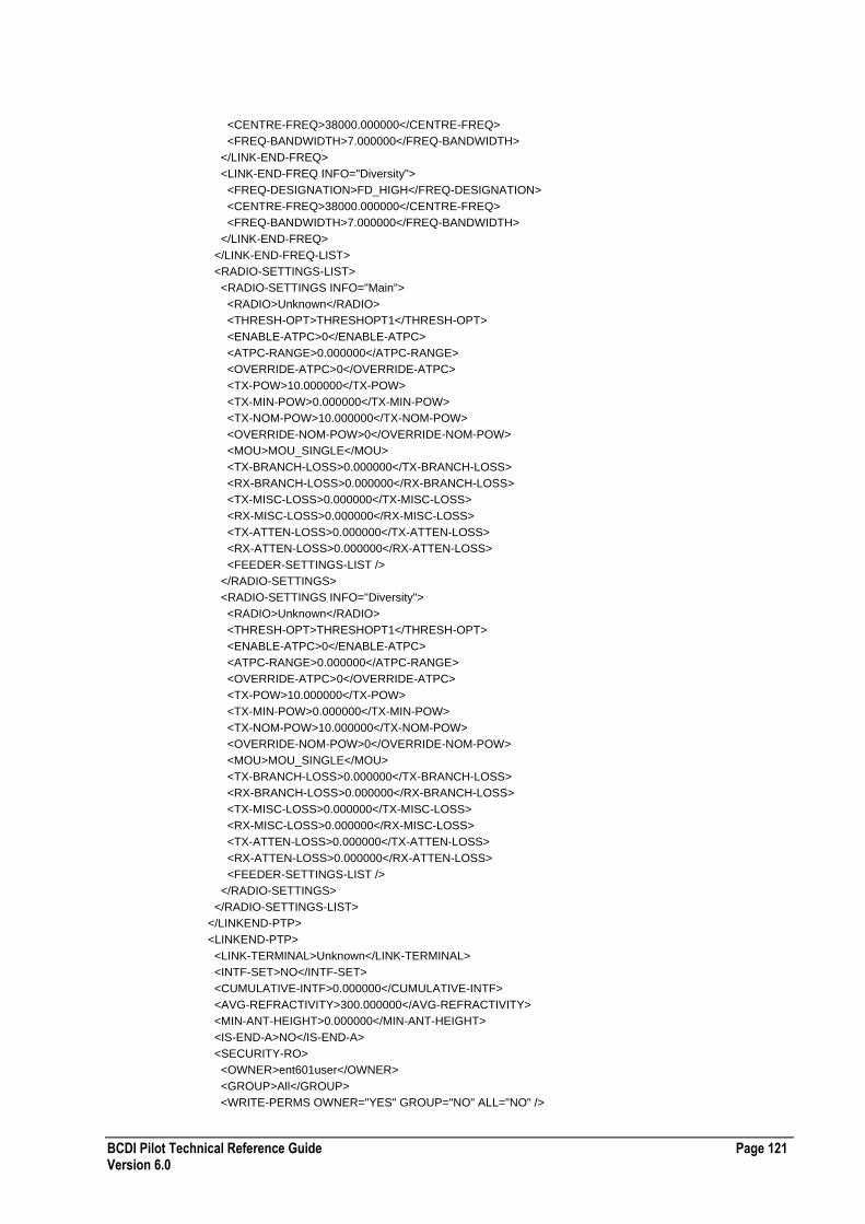
BCDI Pilot Technical Reference Guide Page 121 Version 6.0
<CENTRE-FREQ>38000.000000</CENTRE-FREQ>
<FREQ-BANDWIDTH>7.000000</FREQ-BANDWIDTH>
</LINK-END-FREQ>
<LINK-END-FREQ INFO="Diversity">
<FREQ-DESIGNATION>FD_HIGH</FREQ-DESIGNATION>
<CENTRE-FREQ>38000.000000</CENTRE-FREQ>
<FREQ-BANDWIDTH>7.000000</FREQ-BANDWIDTH>
</LINK-END-FREQ>
</LINK-END-FREQ-LIST>
<RADIO-SETTINGS-LIST>
<RADIO-SETTINGS INFO="Main">
<RADIO>Unknown</RADIO>
<THRESH-OPT>THRESHOPT1</THRESH-OPT>
<ENABLE-ATPC>0</ENABLE-ATPC>
<ATPC-RANGE>0.000000</ATPC-RANGE>
<OVERRIDE-ATPC>0</OVERRIDE-ATPC>
<TX-POW>10.000000</TX-POW>
<TX-MIN-POW>0.000000</TX-MIN-POW>
<TX-NOM-POW>10.000000</TX-NOM-POW>
<OVERRIDE-NOM-POW>0</OVERRIDE-NOM-POW>
<MOU>MOU_SINGLE</MOU>
<TX-BRANCH-LOSS>0.000000</TX-BRANCH-LOSS>
<RX-BRANCH-LOSS>0.000000</RX-BRANCH-LOSS>
<TX-MISC-LOSS>0.000000</TX-MISC-LOSS>
<RX-MISC-LOSS>0.000000</RX-MISC-LOSS>
<TX-ATTEN-LOSS>0.000000</TX-ATTEN-LOSS>
<RX-ATTEN-LOSS>0.000000</RX-ATTEN-LOSS>
<FEEDER-SETTINGS-LIST />
</RADIO-SETTINGS>
<RADIO-SETTINGS INFO="Diversity">
<RADIO>Unknown</RADIO>
<THRESH-OPT>THRESHOPT1</THRESH-OPT>
<ENABLE-ATPC>0</ENABLE-ATPC>
<ATPC-RANGE>0.000000</ATPC-RANGE>
<OVERRIDE-ATPC>0</OVERRIDE-ATPC>
<TX-POW>10.000000</TX-POW>
<TX-MIN-POW>0.000000</TX-MIN-POW>
<TX-NOM-POW>10.000000</TX-NOM-POW>
<OVERRIDE-NOM-POW>0</OVERRIDE-NOM-POW>
<MOU>MOU_SINGLE</MOU>
<TX-BRANCH-LOSS>0.000000</TX-BRANCH-LOSS>
<RX-BRANCH-LOSS>0.000000</RX-BRANCH-LOSS>
<TX-MISC-LOSS>0.000000</TX-MISC-LOSS>
<RX-MISC-LOSS>0.000000</RX-MISC-LOSS>
<TX-ATTEN-LOSS>0.000000</TX-ATTEN-LOSS>
<RX-ATTEN-LOSS>0.000000</RX-ATTEN-LOSS>
<FEEDER-SETTINGS-LIST />
</RADIO-SETTINGS>
</RADIO-SETTINGS-LIST>
</LINKEND-PTP>
<LINKEND-PTP>
<LINK-TERMINAL>Unknown</LINK-TERMINAL>
<INTF-SET>NO</INTF-SET>
<CUMULATIVE-INTF>0.000000</CUMULATIVE-INTF>
<AVG-REFRACTIVITY>300.000000</AVG-REFRACTIVITY>
<MIN-ANT-HEIGHT>0.000000</MIN-ANT-HEIGHT>
<IS-END-A>NO</IS-END-A>
<SECURITY-RO>
<OWNER>ent601user</OWNER>
<GROUP>All</GROUP>
<WRITE-PERMS OWNER="YES" GROUP="NO" ALL="NO" />

Page 122 BCDI Pilot Technical Reference Guide Version 6.0
<CREATED>2007-04-25 14:56:52 ent601user</CREATED>
<MODIFIED>2007-04-25 14:56:52 ent601user</MODIFIED>
</SECURITY-RO>
<LINK-END-FREQ-LIST>
<LINK-END-FREQ INFO="Main">
<FREQ-DESIGNATION>FD_HIGH</FREQ-DESIGNATION>
<CENTRE-FREQ>38000.000000</CENTRE-FREQ>
<FREQ-BANDWIDTH>7.000000</FREQ-BANDWIDTH>
</LINK-END-FREQ>
<LINK-END-FREQ INFO="Diversity">
<FREQ-DESIGNATION>FD_HIGH</FREQ-DESIGNATION>
<CENTRE-FREQ>38000.000000</CENTRE-FREQ>
<FREQ-BANDWIDTH>7.000000</FREQ-BANDWIDTH>
</LINK-END-FREQ>
</LINK-END-FREQ-LIST>
<RADIO-SETTINGS-LIST>
<RADIO-SETTINGS INFO="Main">
<RADIO>Unknown</RADIO>
<THRESH-OPT>THRESHOPT1</THRESH-OPT>
<ENABLE-ATPC>0</ENABLE-ATPC>
<ATPC-RANGE>0.000000</ATPC-RANGE>
<OVERRIDE-ATPC>0</OVERRIDE-ATPC>
<TX-POW>10.000000</TX-POW>
<TX-MIN-POW>0.000000</TX-MIN-POW>
<TX-NOM-POW>10.000000</TX-NOM-POW>
<OVERRIDE-NOM-POW>0</OVERRIDE-NOM-POW>
<MOU>MOU_SINGLE</MOU>
<TX-BRANCH-LOSS>0.000000</TX-BRANCH-LOSS>
<RX-BRANCH-LOSS>0.000000</RX-BRANCH-LOSS>
<TX-MISC-LOSS>0.000000</TX-MISC-LOSS>
<RX-MISC-LOSS>0.000000</RX-MISC-LOSS>
<TX-ATTEN-LOSS>0.000000</TX-ATTEN-LOSS>
<RX-ATTEN-LOSS>0.000000</RX-ATTEN-LOSS>
<FEEDER-SETTINGS-LIST />
</RADIO-SETTINGS>
<RADIO-SETTINGS INFO="Diversity">
<RADIO>Unknown</RADIO>
<THRESH-OPT>THRESHOPT1</THRESH-OPT>
<ENABLE-ATPC>0</ENABLE-ATPC>
<ATPC-RANGE>0.000000</ATPC-RANGE>
<OVERRIDE-ATPC>0</OVERRIDE-ATPC>
<TX-POW>10.000000</TX-POW>
<TX-MIN-POW>0.000000</TX-MIN-POW>
<TX-NOM-POW>10.000000</TX-NOM-POW>
<OVERRIDE-NOM-POW>0</OVERRIDE-NOM-POW>
<MOU>MOU_SINGLE</MOU>
<TX-BRANCH-LOSS>0.000000</TX-BRANCH-LOSS>
<RX-BRANCH-LOSS>0.000000</RX-BRANCH-LOSS>
<TX-MISC-LOSS>0.000000</TX-MISC-LOSS>
<RX-MISC-LOSS>0.000000</RX-MISC-LOSS>
<TX-ATTEN-LOSS>0.000000</TX-ATTEN-LOSS>
<RX-ATTEN-LOSS>0.000000</RX-ATTEN-LOSS>
<FEEDER-SETTINGS-LIST />
</RADIO-SETTINGS>
</RADIO-SETTINGS-LIST>
</LINKEND-PTP>
</LINKEND-PTP-LIST>
</RADIO-LINK>
<RADIO-LINK ID="DPL1_RL2">
<NAME-1 />
<NAME-2 />
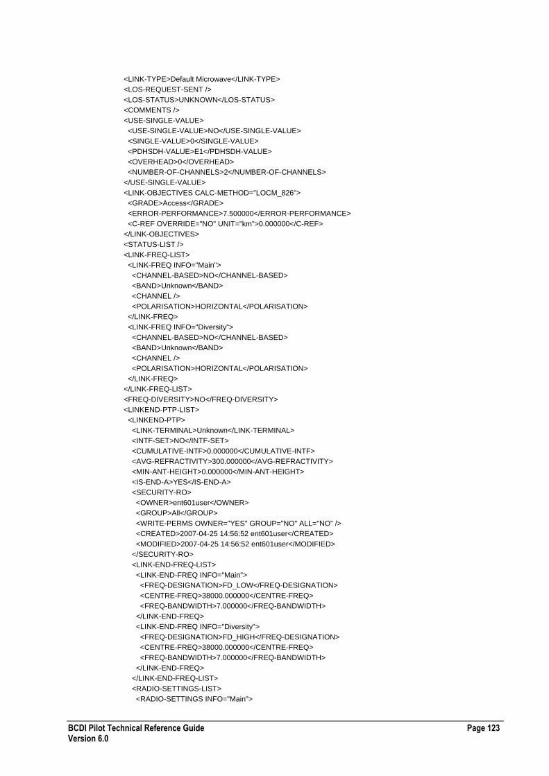
BCDI Pilot Technical Reference Guide Page 123 Version 6.0
<LINK-TYPE>Default Microwave</LINK-TYPE>
<LOS-REQUEST-SENT />
<LOS-STATUS>UNKNOWN</LOS-STATUS>
<COMMENTS />
<USE-SINGLE-VALUE>
<USE-SINGLE-VALUE>NO</USE-SINGLE-VALUE>
<SINGLE-VALUE>0</SINGLE-VALUE>
<PDHSDH-VALUE>E1</PDHSDH-VALUE>
<OVERHEAD>0</OVERHEAD>
<NUMBER-OF-CHANNELS>2</NUMBER-OF-CHANNELS>
</USE-SINGLE-VALUE>
<LINK-OBJECTIVES CALC-METHOD="LOCM_826">
<GRADE>Access</GRADE>
<ERROR-PERFORMANCE>7.500000</ERROR-PERFORMANCE>
<C-REF OVERRIDE="NO" UNIT="km">0.000000</C-REF>
</LINK-OBJECTIVES>
<STATUS-LIST />
<LINK-FREQ-LIST>
<LINK-FREQ INFO="Main">
<CHANNEL-BASED>NO</CHANNEL-BASED>
<BAND>Unknown</BAND>
<CHANNEL />
<POLARISATION>HORIZONTAL</POLARISATION>
</LINK-FREQ>
<LINK-FREQ INFO="Diversity">
<CHANNEL-BASED>NO</CHANNEL-BASED>
<BAND>Unknown</BAND>
<CHANNEL />
<POLARISATION>HORIZONTAL</POLARISATION>
</LINK-FREQ>
</LINK-FREQ-LIST>
<FREQ-DIVERSITY>NO</FREQ-DIVERSITY>
<LINKEND-PTP-LIST>
<LINKEND-PTP>
<LINK-TERMINAL>Unknown</LINK-TERMINAL>
<INTF-SET>NO</INTF-SET>
<CUMULATIVE-INTF>0.000000</CUMULATIVE-INTF>
<AVG-REFRACTIVITY>300.000000</AVG-REFRACTIVITY>
<MIN-ANT-HEIGHT>0.000000</MIN-ANT-HEIGHT>
<IS-END-A>YES</IS-END-A>
<SECURITY-RO>
<OWNER>ent601user</OWNER>
<GROUP>All</GROUP>
<WRITE-PERMS OWNER="YES" GROUP="NO" ALL="NO" />
<CREATED>2007-04-25 14:56:52 ent601user</CREATED>
<MODIFIED>2007-04-25 14:56:52 ent601user</MODIFIED>
</SECURITY-RO>
<LINK-END-FREQ-LIST>
<LINK-END-FREQ INFO="Main">
<FREQ-DESIGNATION>FD_LOW</FREQ-DESIGNATION>
<CENTRE-FREQ>38000.000000</CENTRE-FREQ>
<FREQ-BANDWIDTH>7.000000</FREQ-BANDWIDTH>
</LINK-END-FREQ>
<LINK-END-FREQ INFO="Diversity">
<FREQ-DESIGNATION>FD_HIGH</FREQ-DESIGNATION>
<CENTRE-FREQ>38000.000000</CENTRE-FREQ>
<FREQ-BANDWIDTH>7.000000</FREQ-BANDWIDTH>
</LINK-END-FREQ>
</LINK-END-FREQ-LIST>
<RADIO-SETTINGS-LIST>
<RADIO-SETTINGS INFO="Main">

Page 124 BCDI Pilot Technical Reference Guide Version 6.0
<RADIO>Unknown</RADIO>
<THRESH-OPT>THRESHOPT1</THRESH-OPT>
<ENABLE-ATPC>0</ENABLE-ATPC>
<ATPC-RANGE>0.000000</ATPC-RANGE>
<OVERRIDE-ATPC>0</OVERRIDE-ATPC>
<TX-POW>10.000000</TX-POW>
<TX-MIN-POW>0.000000</TX-MIN-POW>
<TX-NOM-POW>10.000000</TX-NOM-POW>
<OVERRIDE-NOM-POW>0</OVERRIDE-NOM-POW>
<MOU>MOU_SINGLE</MOU>
<TX-BRANCH-LOSS>0.000000</TX-BRANCH-LOSS>
<RX-BRANCH-LOSS>0.000000</RX-BRANCH-LOSS>
<TX-MISC-LOSS>0.000000</TX-MISC-LOSS>
<RX-MISC-LOSS>0.000000</RX-MISC-LOSS>
<TX-ATTEN-LOSS>0.000000</TX-ATTEN-LOSS>
<RX-ATTEN-LOSS>0.000000</RX-ATTEN-LOSS>
<FEEDER-SETTINGS-LIST />
</RADIO-SETTINGS>
<RADIO-SETTINGS INFO="Diversity">
<RADIO>Unknown</RADIO>
<THRESH-OPT>THRESHOPT1</THRESH-OPT>
<ENABLE-ATPC>0</ENABLE-ATPC>
<ATPC-RANGE>0.000000</ATPC-RANGE>
<OVERRIDE-ATPC>0</OVERRIDE-ATPC>
<TX-POW>10.000000</TX-POW>
<TX-MIN-POW>0.000000</TX-MIN-POW>
<TX-NOM-POW>10.000000</TX-NOM-POW>
<OVERRIDE-NOM-POW>0</OVERRIDE-NOM-POW>
<MOU>MOU_SINGLE</MOU>
<TX-BRANCH-LOSS>0.000000</TX-BRANCH-LOSS>
<RX-BRANCH-LOSS>0.000000</RX-BRANCH-LOSS>
<TX-MISC-LOSS>0.000000</TX-MISC-LOSS>
<RX-MISC-LOSS>0.000000</RX-MISC-LOSS>
<TX-ATTEN-LOSS>0.000000</TX-ATTEN-LOSS>
<RX-ATTEN-LOSS>0.000000</RX-ATTEN-LOSS>
<FEEDER-SETTINGS-LIST />
</RADIO-SETTINGS>
</RADIO-SETTINGS-LIST>
</LINKEND-PTP>
<LINKEND-PTP>
<LINK-TERMINAL>Unknown</LINK-TERMINAL>
<INTF-SET>NO</INTF-SET>
<CUMULATIVE-INTF>0.000000</CUMULATIVE-INTF>
<AVG-REFRACTIVITY>300.000000</AVG-REFRACTIVITY>
<MIN-ANT-HEIGHT>0.000000</MIN-ANT-HEIGHT>
<IS-END-A>NO</IS-END-A>
<SECURITY-RO>
<OWNER>ent601user</OWNER>
<GROUP>All</GROUP>
<WRITE-PERMS OWNER="YES" GROUP="NO" ALL="NO" />
<CREATED>2007-04-25 14:56:52 ent601user</CREATED>
<MODIFIED>2007-04-25 14:56:52 ent601user</MODIFIED>
</SECURITY-RO>
<LINK-END-FREQ-LIST>
<LINK-END-FREQ INFO="Main">
<FREQ-DESIGNATION>FD_HIGH</FREQ-DESIGNATION>
<CENTRE-FREQ>38000.000000</CENTRE-FREQ>
<FREQ-BANDWIDTH>7.000000</FREQ-BANDWIDTH>
</LINK-END-FREQ>
<LINK-END-FREQ INFO="Diversity">
<FREQ-DESIGNATION>FD_HIGH</FREQ-DESIGNATION>
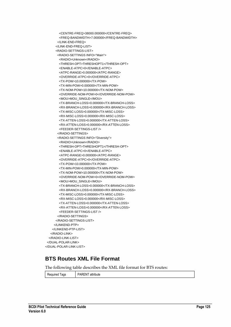
BCDI Pilot Technical Reference Guide Page 125 Version 6.0
<CENTRE-FREQ>38000.000000</CENTRE-FREQ>
<FREQ-BANDWIDTH>7.000000</FREQ-BANDWIDTH>
</LINK-END-FREQ>
</LINK-END-FREQ-LIST>
<RADIO-SETTINGS-LIST>
<RADIO-SETTINGS INFO="Main">
<RADIO>Unknown</RADIO>
<THRESH-OPT>THRESHOPT1</THRESH-OPT>
<ENABLE-ATPC>0</ENABLE-ATPC>
<ATPC-RANGE>0.000000</ATPC-RANGE>
<OVERRIDE-ATPC>0</OVERRIDE-ATPC>
<TX-POW>10.000000</TX-POW>
<TX-MIN-POW>0.000000</TX-MIN-POW>
<TX-NOM-POW>10.000000</TX-NOM-POW>
<OVERRIDE-NOM-POW>0</OVERRIDE-NOM-POW>
<MOU>MOU_SINGLE</MOU>
<TX-BRANCH-LOSS>0.000000</TX-BRANCH-LOSS>
<RX-BRANCH-LOSS>0.000000</RX-BRANCH-LOSS>
<TX-MISC-LOSS>0.000000</TX-MISC-LOSS>
<RX-MISC-LOSS>0.000000</RX-MISC-LOSS>
<TX-ATTEN-LOSS>0.000000</TX-ATTEN-LOSS>
<RX-ATTEN-LOSS>0.000000</RX-ATTEN-LOSS>
<FEEDER-SETTINGS-LIST />
</RADIO-SETTINGS>
<RADIO-SETTINGS INFO="Diversity">
<RADIO>Unknown</RADIO>
<THRESH-OPT>THRESHOPT1</THRESH-OPT>
<ENABLE-ATPC>0</ENABLE-ATPC>
<ATPC-RANGE>0.000000</ATPC-RANGE>
<OVERRIDE-ATPC>0</OVERRIDE-ATPC>
<TX-POW>10.000000</TX-POW>
<TX-MIN-POW>0.000000</TX-MIN-POW>
<TX-NOM-POW>10.000000</TX-NOM-POW>
<OVERRIDE-NOM-POW>0</OVERRIDE-NOM-POW>
<MOU>MOU_SINGLE</MOU>
<TX-BRANCH-LOSS>0.000000</TX-BRANCH-LOSS>
<RX-BRANCH-LOSS>0.000000</RX-BRANCH-LOSS>
<TX-MISC-LOSS>0.000000</TX-MISC-LOSS>
<RX-MISC-LOSS>0.000000</RX-MISC-LOSS>
<TX-ATTEN-LOSS>0.000000</TX-ATTEN-LOSS>
<RX-ATTEN-LOSS>0.000000</RX-ATTEN-LOSS>
<FEEDER-SETTINGS-LIST />
</RADIO-SETTINGS>
</RADIO-SETTINGS-LIST>
</LINKEND-PTP>
</LINKEND-PTP-LIST>
</RADIO-LINK>
</RADIO-LINK-LIST>
</DUAL-POLAR-LINK>
</DUAL-POLAR-LINK-LIST>
BTS Routes XML File Format
The following table describes the XML file format for BTS routes:
Required Tags PARENT attribute
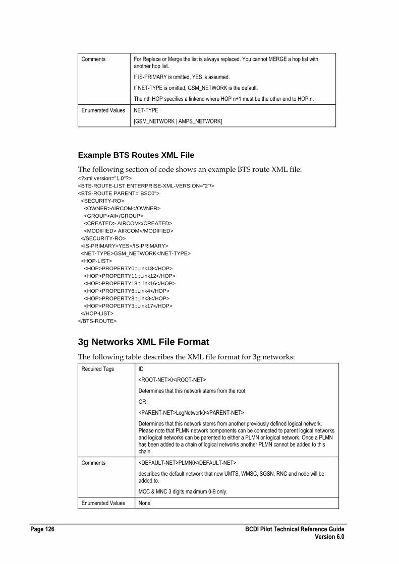
Page 126 BCDI Pilot Technical Reference Guide Version 6.0
Comments For Replace or Merge the list is always replaced. You cannot MERGE a hop list with another hop list.
If IS-PRIMARY is omitted, YES is assumed.
If NET-TYPE is omitted, GSM_NETWORK is the default.
The nth HOP specifies a linkend where HOP n+1 must be the other end to HOP n.
Enumerated Values NET-TYPE
[GSM_NETWORK | AMPS_NETWORK]
Example BTS Routes XML File
The following section of code shows an example BTS route XML file: <?xml version="1.0"?>
<BTS-ROUTE-LIST ENTERPRISE-XML-VERSION="2"/>
<BTS-ROUTE PARENT="BSC0">
<SECURITY-RO>
<OWNER>AIRCOM</OWNER>
<GROUP>All</GROUP>
<CREATED> AIRCOM</CREATED>
<MODIFIED> AIRCOM</MODIFIED>
</SECURITY-RO>
<IS-PRIMARY>YES</IS-PRIMARY>
<NET-TYPE>GSM_NETWORK</NET-TYPE>
<HOP-LIST>
<HOP>PROPERTY0::Link18</HOP>
<HOP>PROPERTY11::Link12</HOP>
<HOP>PROPERTY18::Link16</HOP>
<HOP>PROPERTY6::Link4</HOP>
<HOP>PROPERTY8::Link3</HOP>
<HOP>PROPERTY3::Link17</HOP>
</HOP-LIST>
</BTS-ROUTE>
3g Networks XML File Format
The following table describes the XML file format for 3g networks:
Required Tags ID
<ROOT-NET>0</ROOT-NET>
Determines that this network stems from the root.
OR
<PARENT-NET>LogNetwork0</PARENT-NET>
Determines that this network stems from another previously defined logical network. Please note that PLMN network components can be connected to parent logical networks and logical networks can be parented to either a PLMN or logical network. Once a PLMN has been added to a chain of logical networks another PLMN cannot be added to this chain.
Comments <DEFAULT-NET>PLMN0</DEFAULT-NET>
describes the default network that new UMTS, WMSC, SGSN, RNC and node will be added to.
MCC & MNC 3 digits maximum 0-9 only.
Enumerated Values None

BCDI Pilot Technical Reference Guide Page 127 Version 6.0
Example 3g Networks XML File
The following section of code shows an example 3g networks XML file: <?xml version="1.0" ?>
<NETWORK-LIST ENTERPRISE-XML-VERSION="2">
<DEFAULT-NET>PLMN0</DEFAULT-NET>
<NETWORK-LIST />
<PLMN-LIST>
<PLMN ID="PLMN0">
<SECURITY-RO>
<OWNER>ent5123user</OWNER>
<GROUP>All</GROUP>
<WRITE-PERMS OWNER="YES" GROUP="NO" ALL="NO" />
<CREATED>2005-11-25 19:06:15 ent5123user</CREATED>
<MODIFIED>2005-11-25 19:06:15 ent5123user</MODIFIED>
</SECURITY-RO>
<ROOT-NET>0</ROOT-NET>
<COMMENTS />
<SUBNETWORKID />
<MECONTEXTID />
<STATUS-LIST />
<MCC>000</MCC>
<MNC>000</MNC>
</PLMN>
<PLMN ID="PLMN1">
<SECURITY-RO>
<OWNER>ent5123user</OWNER>
<GROUP>All</GROUP>
<WRITE-PERMS OWNER="YES" GROUP="NO" ALL="NO" />
<CREATED>2005-11-25 19:10:09 ent5123user</CREATED>
<MODIFIED>2005-11-25 19:10:09 ent5123user</MODIFIED>
</SECURITY-RO>
<ROOT-NET>0</ROOT-NET>
<COMMENTS />
<SUBNETWORKID />
<MECONTEXTID />
<STATUS-LIST />
<MCC>000</MCC>
<MNC>000</MNC>
</PLMN>
</PLMN-LIST>
</NETWORK-LIST>
UMTS WMSC XML File Format
The following table describes the XML file format for UMTS WMSCs:
Required Tags ID attribute
PLMN element
NETWORK element
PROPERTY element

Page 128 BCDI Pilot Technical Reference Guide Version 6.0
Comments Relocation to another property is possible.
<PLMN> must be an existing PLMN.
If the node is parented directly to the PLMN then <NETWORK> will be the name of the PLMN. If the node is parented to a Logical Network then <NETWORK> will be the name of an existing Logical Network. This network must be a child of the PLMN specified in the <PLMN> element.
Enumerated Values
None
Example UMTS WMSC XML File
The following section of code shows an example UMTS WMSC XML file: <WMSC-LIST BCDI Pilot-XML-VERSION="1">
<WMSC ID="WMSC0">
<PLMN>PLMN0</PLMN>
<PROPERTY>PROPERTY71</PROPERTY>
<COMMENTS>Comments for UMTS WMSC</COMMENTS>
<NAME1>name 1</NAME1>
<NAME2>name 2</NAME2>
<NETWORK>PLMN0</NETWORK>
<STATUS>
<FLAG GROUP="Group 1" VALUE="Flag 1"/>
<FLAG GROUP="G2" VALUE="f2"/>
</STATUS>
</WMSC>
</WMSC-LIST>
UMTS SGSN XML File Format
The following table describes the XML file format for UMTS SGSNs:
Required Tags ID attribute
PLMN element
NETWORK element
PROPERTY element
Comments Relocation to another property is possible.
<PLMN> must be an existing PLMN.
If the node is parented directly to the PLMN then <NETWORK> will be the name of the PLMN. If the node is parented to a Logical Network then <NETWORK> will be the name of an existing Logical Network. This network must be a child of the PLMN specified in the <PLMN> element.
Enumerated Values None
Example UMTS SGSN XML File
The following section of code shows an example UMTS SGSN XML file: <?xml version="1.0"?>
<SGSN-LIST ENTERPRISE-XML-VERSION="1">
<SGSN ID="SGSN0">
<PLMN>PLMN0</PLMN>
<SECURITY-RO>
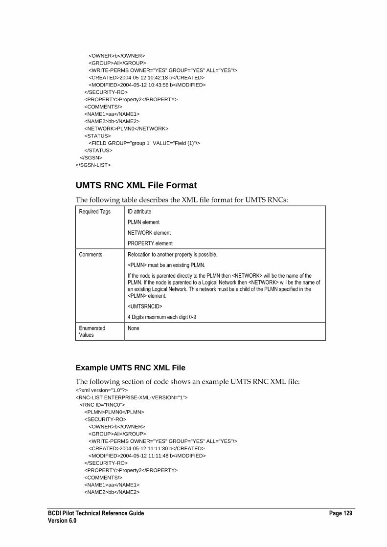
BCDI Pilot Technical Reference Guide Page 129 Version 6.0
<OWNER>b</OWNER>
<GROUP>All</GROUP>
<WRITE-PERMS OWNER="YES" GROUP="YES" ALL="YES"/>
<CREATED>2004-05-12 10:42:18 b</CREATED>
<MODIFIED>2004-05-12 10:43:56 b</MODIFIED>
</SECURITY-RO>
<PROPERTY>Property2</PROPERTY>
<COMMENTS/>
<NAME1>aa</NAME1>
<NAME2>bb</NAME2>
<NETWORK>PLMN0</NETWORK>
<STATUS>
<FIELD GROUP="group 1" VALUE="Field (1)"/>
</STATUS>
</SGSN>
</SGSN-LIST>
UMTS RNC XML File Format
The following table describes the XML file format for UMTS RNCs:
Required Tags ID attribute
PLMN element
NETWORK element
PROPERTY element
Comments Relocation to another property is possible.
<PLMN> must be an existing PLMN.
If the node is parented directly to the PLMN then <NETWORK> will be the name of the PLMN. If the node is parented to a Logical Network then <NETWORK> will be the name of an existing Logical Network. This network must be a child of the PLMN specified in the <PLMN> element.
<UMTSRNCID>
4 Digits maximum each digit 0-9
Enumerated Values
None
Example UMTS RNC XML File
The following section of code shows an example UMTS RNC XML file: <?xml version="1.0"?>
<RNC-LIST ENTERPRISE-XML-VERSION="1">
<RNC ID="RNC0">
<PLMN>PLMN0</PLMN>
<SECURITY-RO>
<OWNER>b</OWNER>
<GROUP>All</GROUP>
<WRITE-PERMS OWNER="YES" GROUP="YES" ALL="YES"/>
<CREATED>2004-05-12 11:11:30 b</CREATED>
<MODIFIED>2004-05-12 11:11:48 b</MODIFIED>
</SECURITY-RO>
<PROPERTY>Property2</PROPERTY>
<COMMENTS/>
<NAME1>aa</NAME1>
<NAME2>bb</NAME2>

Page 130 BCDI Pilot Technical Reference Guide Version 6.0
<NETWORK>PLMN0</NETWORK>
<STATUS>
<FIELD GROUP="group 1" VALUE="Field (1)"/>
</STATUS>
<UMTSRNCID>1</UMTSRNCID>
<FUNCTIONID>3</FUNCTIONID>
<MANAGEDELEMID>2</MANAGEDELEMID>
</RNC>
</RNC-LIST>
UMTS Node B XML File Format
The following table describes the XML file format for UMTS node Bs:
Required Tags ID attribute
PLMN element
NETWORK element
PROPERTY element
Comments Relocation to another Property is possible.
<PLMN> must be an existing PLMN.
If the node is parented directly to the PLMN then <NETWORK> will be the name of the PLMN. If the node is parented to a Logical Network then <NETWORK> will be the name of an existing Logical Network. This network must be a child of the PLMN specified in the <PLMN> element.
<NODEBID>
9 Digits maximum each digit 0-9
In order to import the carriers on the node the carrier name must exist or have been previously imported.
In order to import the antennas correctly the antenna must exist and to connect the propagation model this must exist also.
The sample XML file shows resources allocated to the node, Carrier and Antenna.
Enumerated Values
REPEATER-ANTENNA
[YES | NO]
ANT-MASK-FXD
[YES | NO]
ANT-MODEL-FXD
[YES | NO]
AZI-FXD
[YES | NO]
DOWNTILT-FXD
[YES | NO]
HGHT-FXD
[YES | NO]
USE-BRNGS
[YES | NO]
USE-HGHT-SMOOTHING
[YES | NO]

BCDI Pilot Technical Reference Guide Page 131 Version 6.0
Note : There is a separate format for WiMAX Nodes. For more information, see WiMAX Node XML File Format on page 157.
Example UMTS Node B XML File
The following section of code shows an example UMTS node B XML file: <?xml version="1.0" ?>
<NODEB-LIST ENTERPRISE-XML-VERSION="4">
<NODEB ID="NodeB8">
<HEX-RADIUS>16000.000000</HEX-RADIUS>
<NODEBID>-1</NODEBID>
<TECHNOLOGY>ALL_UMTS</TECHNOLOGY>
<NODEBTYPE>Unknown</NODEBTYPE>
<PLMN>PLMN0</PLMN>
<MCC>000</MCC>
<MNC>000</MNC>
<SECURITY-RO>
<OWNER>Administrator</OWNER>
<GROUP>All</GROUP>
<WRITE-PERMS OWNER="YES" GROUP="NO" ALL="NO" />
<CREATED>2006-06-14 11:20:03 Administrator</CREATED>
<MODIFIED>2006-06-14 11:20:15 Administrator</MODIFIED>
</SECURITY-RO>
<PROPERTY>Property24</PROPERTY>
<COMMENTS />
<NAME1 />
<NAME2 />
<NETWORK>PLMN0</NETWORK>
<STATUS-LIST />
<RES1ULTOT>10000</RES1ULTOT>
<RES1DLTOT>10000</RES1DLTOT>
<RES1ULPRI>5000</RES1ULPRI>
<RES1DLPRI>5000</RES1DLPRI>
<RES1ULHO>5000</RES1ULHO>
<RES1DLHO>5000</RES1DLHO>
<UMTS-CARRIER-LIST>
<UMTS-CARRIER ID="Macrocell 1">
<SECURITY-RO>
<OWNER>ent6023user</OWNER>
<GROUP>All</GROUP>
<WRITE-PERMS OWNER="YES" GROUP="NO" ALL="NO" />
<CREATED>2007-06-28 08:20:23 ent6023user</CREATED>
<MODIFIED>2007-06-28 08:20:23 ent6023user</MODIFIED>
</SECURITY-RO>
</UMTS-CARRIER>
</UMTS-CARRIER-LIST>
<UMTS-ANTENNA-LIST>
<UMTS-ANTENNA>
<ANT-INDEX>1</ANT-INDEX>
<ANT-UL-GAIN-CORRECTION-FACTOR>0.000000</ANT-UL-GAIN-CORRECTION-FACTOR>
<REPEATER-ANTENNA>NO</REPEATER-ANTENNA>
<LOCATION TYPE="REL" UNIT="EN">
<X>0.000000</X>
<Y>0.000000</Y>
</LOCATION>
<SECURITY-RO>
<OWNER>Administrator</OWNER>
<GROUP>All</GROUP>
<WRITE-PERMS OWNER="YES" GROUP="NO" ALL="NO" />
<CREATED>2006-06-14 11:20:03 Administrator</CREATED>

Page 132 BCDI Pilot Technical Reference Guide Version 6.0
<MODIFIED>2006-06-14 11:20:03 Administrator</MODIFIED>
</SECURITY-RO>
<AZIMUTH>60.000000</AZIMUTH>
<DOWN-TILT>0.000000</DOWN-TILT>
<HEIGHT>30.000000</HEIGHT>
<CORR-FACT>0.000000</CORR-FACT>
<ELEC-TILT>3</ELEC-TILT>
<TOTAL-TILT>3.000000</TOTAL-TILT>
<CONSTRAINTS>
<ANT-MASK-FXD>no</ANT-MASK-FXD>
<ANT-MODEL-FXD>no</ANT-MODEL-FXD>
<AZI-FXD>no</AZI-FXD>
<DOWNTILT-FXD>no</DOWNTILT-FXD>
<HGHT-FXD>no</HGHT-FXD>
<MAX-LOBETILT>270</MAX-LOBETILT>
<USE-BRNGS>no</USE-BRNGS>
<CLOCK-BRNG>0</CLOCK-BRNG>
<CCLOCK-BRNG>0</CCLOCK-BRNG>
</CONSTRAINTS>
<ANT-TYPE>60_4_13_SX_1800_R1\60_4_13_SX_1800_R1</ANT-TYPE>
<SHARED-ANT-ID />
<PRIMARY-MODEL-DATA>
<MODEL>2000 Macro</MODEL>
<RADIUS-METRES>3.000000</RADIUS-METRES>
<RADIUS-FT>0.000000</RADIUS-FT>
<RESOLUTION-METRES>50.000000</RESOLUTION-METRES>
<RESOLUTION-FT>0.000000</RESOLUTION-FT>
</PRIMARY-MODEL-DATA>
<SECONDARY-MODEL-DATA>
<MODEL>Unknown</MODEL>
<RADIUS-METRES>0.000000</RADIUS-METRES>
<RADIUS-FT>0.000000</RADIUS-FT>
<RESOLUTION-METRES>0.000000</RESOLUTION-METRES>
<RESOLUTION-FT>0.000000</RESOLUTION-FT>
</SECONDARY-MODEL-DATA>
<PRED-SYSTEM-INFO-RO>
<LOCATION TYPE="ABS" UNIT="EN">
<X>566193</X>
<Y>5449061</Y>
</LOCATION>
<ANTENNA-CRC64>11843294365390217616</ANTENNA-CRC64>
<PRIMARY-DATA>
<MODEL-CRC64>10165167441210095849</MODEL-CRC64>
<ANT-DTM-USING-MT-RES>31.000000</ANT-DTM-USING-MT-RES>
<ANT-DTM-USING-IMP-RES>52.000000</ANT-DTM-USING-IMP-RES>
<USE-HGHT-SMOOTHING>no</USE-HGHT-SMOOTHING>
<PRED-FLAGS>0</PRED-FLAGS>
</PRIMARY-DATA>
<SECONDARY-DATA>
<MODEL-CRC64 />
<ANT-DTM-USING-MT-RES>52.000000</ANT-DTM-USING-MT-RES>
<ANT-DTM-USING-IMP-RES>52.000000</ANT-DTM-USING-IMP-RES>
<USE-HGHT-SMOOTHING>no</USE-HGHT-SMOOTHING>
<PRED-FLAGS>0</PRED-FLAGS>
</SECONDARY-DATA>
</PRED-SYSTEM-INFO-RO>
</UMTS-ANTENNA>
</UMTS-ANTENNA-LIST>
</NODEB>
</NODEB-LIST>
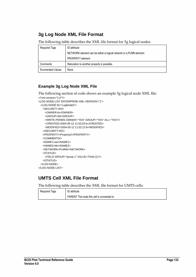
BCDI Pilot Technical Reference Guide Page 133 Version 6.0
3g Log Node XML File Format
The following table describes the XML file format for 3g logical nodes:
Required Tags ID attribute
NETWORK element can be either a logical network or a PLMN element
PROPERTY element
Comments Relocation to another property is possible.
Enumerated Values None
Example 3g Log Node XML File
The following section of code shows an example 3g logical node XML file: <?xml version="1.0"?>
<LOG-NODE-LIST ENTERPRISE-XML-VERSION="1">
<LOG-NODE ID="LogNode0">
<SECURITY-RO>
<OWNER>b</OWNER>
<GROUP>All</GROUP>
<WRITE-PERMS OWNER="YES" GROUP="YES" ALL="YES"/>
<CREATED>2004-05-12 11:52:03 b</CREATED>
<MODIFIED>2004-05-12 11:52:13 b</MODIFIED>
</SECURITY-RO>
<PROPERTY>Property2</PROPERTY>
<COMMENTS/>
<NAME1>aa</NAME1>
<NAME2>bb</NAME2>
<NETWORK>PLMN0</NETWORK>
<STATUS>
<FIELD GROUP="group 1" VALUE="Field (1)"/>
</STATUS>
</LOG-NODE>
</LOG-NODE-LIST>
UMTS Cell XML File Format
The following table describes the XML file format for UMTS cells:
Required Tags ID attribute
PARENT The node this cell is connected to

Page 134 BCDI Pilot Technical Reference Guide Version 6.0
Comments LOCALCELLID Maximum 9 digits each digit 0-9
LAC Maximum 5 digits each digit 0-9
RAC Maximum 3 digits each digit 0-9
SAC Maximum 3 digits each digit 0-9
LCR Unused
UMTS-CELL-FEEDER
ANT-INDEX must be a valid index to the Parent Node antenna.
FEEDER-TYPE and MHA-TYPE must exist already or have been imported otherwise these equipment types will not be set.
MAX-TX-POW-FXD, MAX-DL-POW-FXD, CHAN-POW-FXD are ADVANTAGE-related parameters.
Enumerated Values MULTIPATH-TYPE
[ Heavy Multipath | Light Multipath | Mixed ]
COVERAGE-TYPE
[ Outdoor | Indoor ]
HSDPA-LINKPOWER
[True | False]
Example UMTS Cell XML File
The following section of code shows an example UMTS cell XML file: <?xml version="1.0" ?>
<UMTS-CELL-LIST ENTERPRISE-XML-VERSION="5">
<UMTS-CELL ID="NodeB8C" HSDPA-SUPPORTED="0">
<SECURITY-RO>
<OWNER>demouser</OWNER>
<GROUP>All</GROUP>
<WRITE-PERMS OWNER="YES" GROUP="NO" ALL="NO" />
<CREATED>2006-09-13 15:23:32 demouser</CREATED>
<MODIFIED>2006-09-13 15:23:32 demouser</MODIFIED>
</SECURITY-RO>
<PARENT>NodeB8</PARENT>
<UMTSCELLNAME />
<TECHNOLOGY-RO>ALL_UMTS</TECHNOLOGY-RO>
<UMTSCELLID>Unknown</UMTSCELLID>
<LOCALCELLID>Unknown</LOCALCELLID>
<LAC>Unknown</LAC>
<SAC>Unknown</SAC>
<RAC>Unknown</RAC>
<LCR>0</LCR>
<URA1>Unknown</URA1>
<URA2>Unknown</URA2>
<URA3>Unknown</URA3>
<URA4>Unknown</URA4>
<URA5>Unknown</URA5>
<URA6>Unknown</URA6>
<URA7>Unknown</URA7>
<URA8>Unknown</URA8>
<STATUS-LIST />
<WLCSEID>Unknown</WLCSEID>
<MULTIPATH-TYPE>Light Multipath</MULTIPATH-TYPE>
<COVERAGE-TYPE>Outdoor</COVERAGE-TYPE>
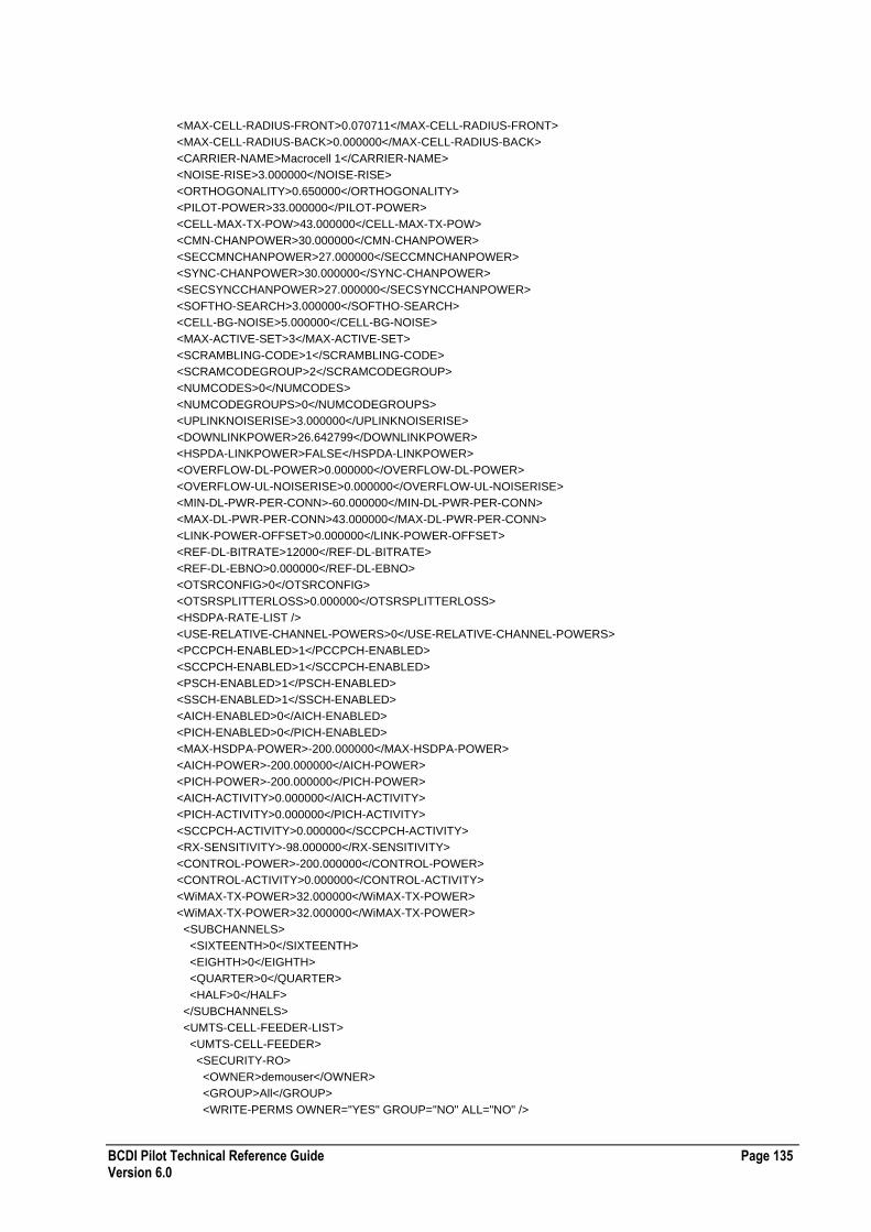
BCDI Pilot Technical Reference Guide Page 135 Version 6.0
<MAX-CELL-RADIUS-FRONT>0.070711</MAX-CELL-RADIUS-FRONT>
<MAX-CELL-RADIUS-BACK>0.000000</MAX-CELL-RADIUS-BACK>
<CARRIER-NAME>Macrocell 1</CARRIER-NAME>
<NOISE-RISE>3.000000</NOISE-RISE>
<ORTHOGONALITY>0.650000</ORTHOGONALITY>
<PILOT-POWER>33.000000</PILOT-POWER>
<CELL-MAX-TX-POW>43.000000</CELL-MAX-TX-POW>
<CMN-CHANPOWER>30.000000</CMN-CHANPOWER>
<SECCMNCHANPOWER>27.000000</SECCMNCHANPOWER>
<SYNC-CHANPOWER>30.000000</SYNC-CHANPOWER>
<SECSYNCCHANPOWER>27.000000</SECSYNCCHANPOWER>
<SOFTHO-SEARCH>3.000000</SOFTHO-SEARCH>
<CELL-BG-NOISE>5.000000</CELL-BG-NOISE>
<MAX-ACTIVE-SET>3</MAX-ACTIVE-SET>
<SCRAMBLING-CODE>1</SCRAMBLING-CODE>
<SCRAMCODEGROUP>2</SCRAMCODEGROUP>
<NUMCODES>0</NUMCODES>
<NUMCODEGROUPS>0</NUMCODEGROUPS>
<UPLINKNOISERISE>3.000000</UPLINKNOISERISE>
<DOWNLINKPOWER>26.642799</DOWNLINKPOWER>
<HSPDA-LINKPOWER>FALSE</HSPDA-LINKPOWER>
<OVERFLOW-DL-POWER>0.000000</OVERFLOW-DL-POWER>
<OVERFLOW-UL-NOISERISE>0.000000</OVERFLOW-UL-NOISERISE>
<MIN-DL-PWR-PER-CONN>-60.000000</MIN-DL-PWR-PER-CONN>
<MAX-DL-PWR-PER-CONN>43.000000</MAX-DL-PWR-PER-CONN>
<LINK-POWER-OFFSET>0.000000</LINK-POWER-OFFSET>
<REF-DL-BITRATE>12000</REF-DL-BITRATE>
<REF-DL-EBNO>0.000000</REF-DL-EBNO>
<OTSRCONFIG>0</OTSRCONFIG>
<OTSRSPLITTERLOSS>0.000000</OTSRSPLITTERLOSS>
<HSDPA-RATE-LIST />
<USE-RELATIVE-CHANNEL-POWERS>0</USE-RELATIVE-CHANNEL-POWERS>
<PCCPCH-ENABLED>1</PCCPCH-ENABLED>
<SCCPCH-ENABLED>1</SCCPCH-ENABLED>
<PSCH-ENABLED>1</PSCH-ENABLED>
<SSCH-ENABLED>1</SSCH-ENABLED>
<AICH-ENABLED>0</AICH-ENABLED>
<PICH-ENABLED>0</PICH-ENABLED>
<MAX-HSDPA-POWER>-200.000000</MAX-HSDPA-POWER>
<AICH-POWER>-200.000000</AICH-POWER>
<PICH-POWER>-200.000000</PICH-POWER>
<AICH-ACTIVITY>0.000000</AICH-ACTIVITY>
<PICH-ACTIVITY>0.000000</PICH-ACTIVITY>
<SCCPCH-ACTIVITY>0.000000</SCCPCH-ACTIVITY>
<RX-SENSITIVITY>-98.000000</RX-SENSITIVITY>
<CONTROL-POWER>-200.000000</CONTROL-POWER>
<CONTROL-ACTIVITY>0.000000</CONTROL-ACTIVITY>
<WiMAX-TX-POWER>32.000000</WiMAX-TX-POWER>
<WiMAX-TX-POWER>32.000000</WiMAX-TX-POWER>
<SUBCHANNELS>
<SIXTEENTH>0</SIXTEENTH>
<EIGHTH>0</EIGHTH>
<QUARTER>0</QUARTER>
<HALF>0</HALF>
</SUBCHANNELS>
<UMTS-CELL-FEEDER-LIST>
<UMTS-CELL-FEEDER>
<SECURITY-RO>
<OWNER>demouser</OWNER>
<GROUP>All</GROUP>
<WRITE-PERMS OWNER="YES" GROUP="NO" ALL="NO" />
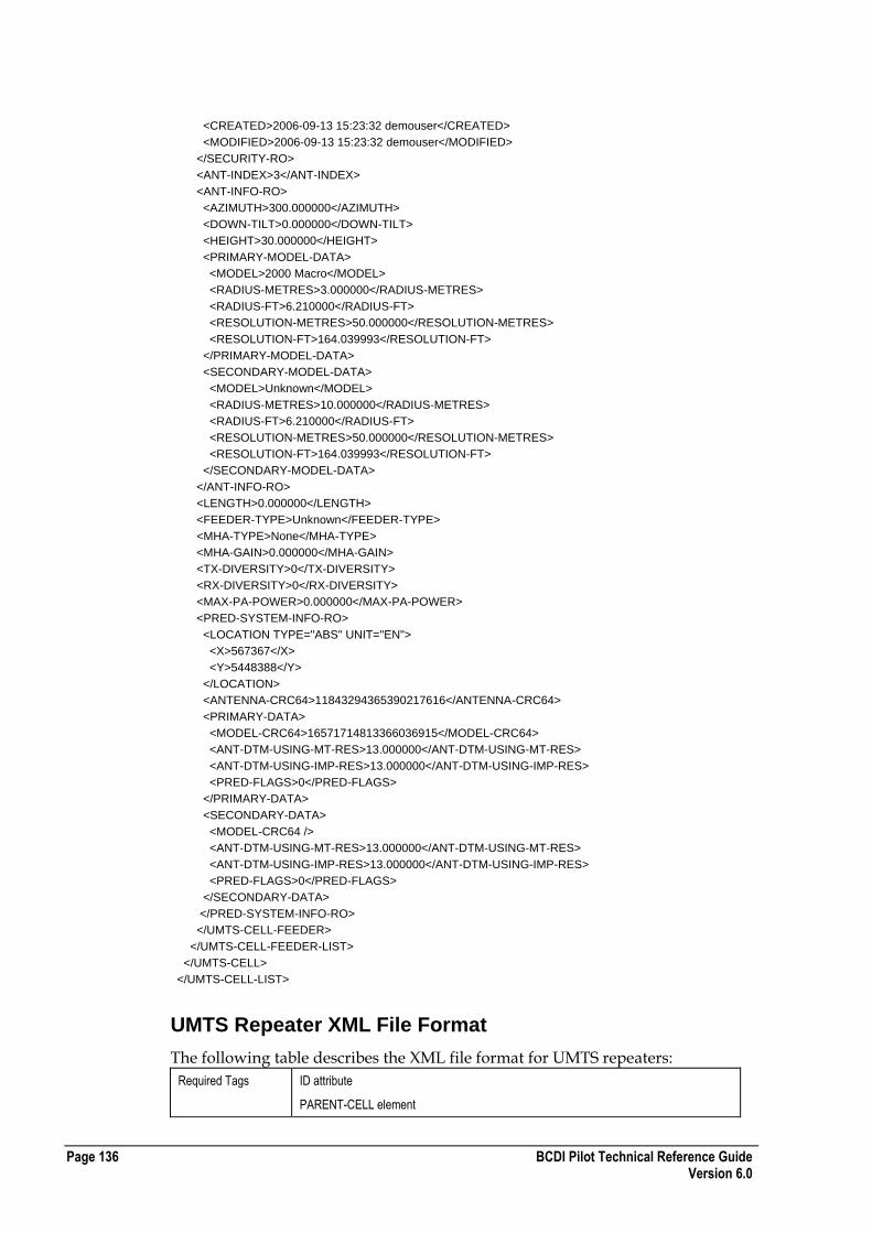
Page 136 BCDI Pilot Technical Reference Guide Version 6.0
<CREATED>2006-09-13 15:23:32 demouser</CREATED>
<MODIFIED>2006-09-13 15:23:32 demouser</MODIFIED>
</SECURITY-RO>
<ANT-INDEX>3</ANT-INDEX>
<ANT-INFO-RO>
<AZIMUTH>300.000000</AZIMUTH>
<DOWN-TILT>0.000000</DOWN-TILT>
<HEIGHT>30.000000</HEIGHT>
<PRIMARY-MODEL-DATA>
<MODEL>2000 Macro</MODEL>
<RADIUS-METRES>3.000000</RADIUS-METRES>
<RADIUS-FT>6.210000</RADIUS-FT>
<RESOLUTION-METRES>50.000000</RESOLUTION-METRES>
<RESOLUTION-FT>164.039993</RESOLUTION-FT>
</PRIMARY-MODEL-DATA>
<SECONDARY-MODEL-DATA>
<MODEL>Unknown</MODEL>
<RADIUS-METRES>10.000000</RADIUS-METRES>
<RADIUS-FT>6.210000</RADIUS-FT>
<RESOLUTION-METRES>50.000000</RESOLUTION-METRES>
<RESOLUTION-FT>164.039993</RESOLUTION-FT>
</SECONDARY-MODEL-DATA>
</ANT-INFO-RO>
<LENGTH>0.000000</LENGTH>
<FEEDER-TYPE>Unknown</FEEDER-TYPE>
<MHA-TYPE>None</MHA-TYPE>
<MHA-GAIN>0.000000</MHA-GAIN>
<TX-DIVERSITY>0</TX-DIVERSITY>
<RX-DIVERSITY>0</RX-DIVERSITY>
<MAX-PA-POWER>0.000000</MAX-PA-POWER>
<PRED-SYSTEM-INFO-RO>
<LOCATION TYPE="ABS" UNIT="EN">
<X>567367</X>
<Y>5448388</Y>
</LOCATION>
<ANTENNA-CRC64>11843294365390217616</ANTENNA-CRC64>
<PRIMARY-DATA>
<MODEL-CRC64>16571714813366036915</MODEL-CRC64>
<ANT-DTM-USING-MT-RES>13.000000</ANT-DTM-USING-MT-RES>
<ANT-DTM-USING-IMP-RES>13.000000</ANT-DTM-USING-IMP-RES>
<PRED-FLAGS>0</PRED-FLAGS>
</PRIMARY-DATA>
<SECONDARY-DATA>
<MODEL-CRC64 />
<ANT-DTM-USING-MT-RES>13.000000</ANT-DTM-USING-MT-RES>
<ANT-DTM-USING-IMP-RES>13.000000</ANT-DTM-USING-IMP-RES>
<PRED-FLAGS>0</PRED-FLAGS>
</SECONDARY-DATA>
</PRED-SYSTEM-INFO-RO>
</UMTS-CELL-FEEDER>
</UMTS-CELL-FEEDER-LIST>
</UMTS-CELL>
</UMTS-CELL-LIST>
UMTS Repeater XML File Format
The following table describes the XML file format for UMTS repeaters:
Required Tags ID attribute
PARENT-CELL element
BCDI Pilot Technical Reference Guide Page 137 Version 6.0
Comments NONE
Enumerated Values ANT-MASK-FXD
[YES | NO]
ANT-MODEL-FXD
[YES | NO]
AZI-FXD
[YES | NO]
DOWNTILT-FXD
[YES | NO]
HGHT-FXD
[YES | NO]
USE-BRNGS
[YES | NO]
TX-DIVERSITY
[YES | NO]
RX-DIVERSITY
[YES | NO]
USE-HGHT-SMOOTHING
[YES | NO]
Example UMTS Repeater XML File
The following section of code shows an example UMTS repeater XML file: <?xml version="1.0" ?>
<UMTS-REPEATER-LIST ENTERPRISE-XML-VERSION="2">
<UMTS-REPEATER ID="UMTS1">
<TECHNOLOGY-RO>ALL_UMTS</TECHNOLOGY-RO>
<PARENT-CELL>NodeB8C</PARENT-CELL>
<SECURITY-RO>
<OWNER>Administrator</OWNER>
<GROUP>All</GROUP>
<WRITE-PERMS OWNER="YES" GROUP="NO" ALL="NO" />
<CREATED>2006-06-16 11:26:17 Administrator</CREATED>
<MODIFIED>2006-06-16 11:28:03 Administrator</MODIFIED>
</SECURITY-RO>
<PROPERTY>Property12</PROPERTY>
<COMMENTS />
<NAME1 />
<NAME2 />
<NETWORK>PLMN0</NETWORK>
<STATUS-LIST />
<PLMN>PLMN0</PLMN>
<ANTENNA-RX>
<LOCATION TYPE="REL" UNIT="EN">
<X>0.000000</X>
<Y>0.000000</Y>
</LOCATION>
<SECURITY-RO>
<OWNER>Administrator</OWNER>
<GROUP>All</GROUP>
Page 138 BCDI Pilot Technical Reference Guide Version 6.0
<WRITE-PERMS OWNER="YES" GROUP="NO" ALL="NO" />
<CREATED>2006-06-16 11:26:18 Administrator</CREATED>
<MODIFIED>2006-06-16 11:28:03 Administrator</MODIFIED>
</SECURITY-RO>
<AZIMUTH>0.000000</AZIMUTH>
<DOWN-TILT>0.000000</DOWN-TILT>
<HEIGHT>15.000000</HEIGHT>
<CORR-FACT>0.000000</CORR-FACT>
<ELEC-TILT>0</ELEC-TILT>
<TOTAL-TILT>0.000000</TOTAL-TILT>
<CONSTRAINTS>
<ANT-MASK-FXD>no</ANT-MASK-FXD>
<ANT-MODEL-FXD>no</ANT-MODEL-FXD>
<AZI-FXD>no</AZI-FXD>
<DOWNTILT-FXD>no</DOWNTILT-FXD>
<HGHT-FXD>no</HGHT-FXD>
<MAX-LOBETILT>270</MAX-LOBETILT>
<USE-BRNGS>no</USE-BRNGS>
<CLOCK-BRNG>0</CLOCK-BRNG>
<CCLOCK-BRNG>0</CCLOCK-BRNG>
</CONSTRAINTS>
<ANT-TYPE>360_0_14\360_0_14</ANT-TYPE>
<SHARED-ANT-ID />
<FEEDER ID="F - 13GHz">
<LENGTH>2</LENGTH>
<LOSS>0</LOSS>
</FEEDER>
<MHA-TYPE ID="MHA">
<MHA-GAIN>0.000000</MHA-GAIN>
</MHA-TYPE>
<TX-DIVERSITY>NO</TX-DIVERSITY>
<RX-DIVERSITY>NO</RX-DIVERSITY>
</ANTENNA-RX>
<ANTENNA-TX>
<LOCATION TYPE="REL" UNIT="EN">
<X>0.000000</X>
<Y>0.000000</Y>
</LOCATION>
<SECURITY-RO>
<OWNER>Administrator</OWNER>
<GROUP>All</GROUP>
<WRITE-PERMS OWNER="YES" GROUP="NO" ALL="NO" />
<CREATED>2006-06-16 11:26:18 Administrator</CREATED>
<MODIFIED>2006-06-16 11:28:03 Administrator</MODIFIED>
</SECURITY-RO>
<AZIMUTH>0.000000</AZIMUTH>
<DOWN-TILT>0.000000</DOWN-TILT>
<HEIGHT>15.000000</HEIGHT>
<CORR-FACT>0.000000</CORR-FACT>
<ELEC-TILT>0</ELEC-TILT>
<TOTAL-TILT>0.000000</TOTAL-TILT>
<CONSTRAINTS>
<ANT-MASK-FXD>no</ANT-MASK-FXD>
<ANT-MODEL-FXD>no</ANT-MODEL-FXD>
<AZI-FXD>no</AZI-FXD>
<DOWNTILT-FXD>no</DOWNTILT-FXD>
<HGHT-FXD>no</HGHT-FXD>
<MAX-LOBETILT>270</MAX-LOBETILT>
<USE-BRNGS>no</USE-BRNGS>
<CLOCK-BRNG>0</CLOCK-BRNG>
<CCLOCK-BRNG>0</CCLOCK-BRNG>

BCDI Pilot Technical Reference Guide Page 139 Version 6.0
</CONSTRAINTS>
<ANT-TYPE>360_0_14\360_0_14</ANT-TYPE>
<SHARED-ANT-ID />
<PRIMARY-MODEL-DATA>
<MODEL>Unknown</MODEL>
<RADIUS-METRES>10.000000</RADIUS-METRES>
<RADIUS-FT>0.000000</RADIUS-FT>
<RESOLUTION-METRES>50.000000</RESOLUTION-METRES>
<RESOLUTION-FT>0.000000</RESOLUTION-FT>
</PRIMARY-MODEL-DATA>
<SECONDARY-MODEL-DATA>
<MODEL>Unknown</MODEL>
<RADIUS-METRES>0.000000</RADIUS-METRES>
<RADIUS-FT>0.000000</RADIUS-FT>
<RESOLUTION-METRES>0.000000</RESOLUTION-METRES>
<RESOLUTION-FT>0.000000</RESOLUTION-FT>
</SECONDARY-MODEL-DATA>
<PRED-SYSTEM-INFO-RO>
<LOCATION TYPE="ABS" UNIT="EN">
<X>564025</X>
<Y>5450475</Y>
</LOCATION>
<ANTENNA-CRC64>11145571760223824810</ANTENNA-CRC64>
<PRIMARY-DATA>
<MODEL-CRC64 />
<ANT-DTM-USING-MT-RES>40.000000</ANT-DTM-USING-MT-RES>
<ANT-DTM-USING-IMP-RES>22.000000</ANT-DTM-USING-IMP-RES>
<USE-HGHT-SMOOTHING>no</USE-HGHT-SMOOTHING>
<PRED-FLAGS>0</PRED-FLAGS>
</PRIMARY-DATA>
<SECONDARY-DATA>
<MODEL-CRC64 />
<ANT-DTM-USING-MT-RES>22.000000</ANT-DTM-USING-MT-RES>
<ANT-DTM-USING-IMP-RES>22.000000</ANT-DTM-USING-IMP-RES>
<USE-HGHT-SMOOTHING>no</USE-HGHT-SMOOTHING>
<PRED-FLAGS>0</PRED-FLAGS>
</SECONDARY-DATA>
</PRED-SYSTEM-INFO-RO>
<FEEDER ID="F - 13GHz">
<LENGTH>2</LENGTH>
<LOSS>0</LOSS>
</FEEDER>
<MHA-TYPE ID="MHA">
<MHA-GAIN>0.000000</MHA-GAIN>
</MHA-TYPE>
<TX-DIVERSITY>NO</TX-DIVERSITY>
<RX-DIVERSITY>NO</RX-DIVERSITY>
<PRED-MODEL>Unknown</PRED-MODEL>
</ANTENNA-TX>
<DL-GAIN>0.000000</DL-GAIN>
<UL-GAIN>0.000000</UL-GAIN>
<UL-NOISE_FACTOR>0.000000</UL-NOISE_FACTOR>
<PRED-RESOLUTION>50</PRED-RESOLUTION>
</UMTS-REPEATER>
</UMTS-REPEATER-LIST>
Page 140 BCDI Pilot Technical Reference Guide Version 6.0
LMU XML File Format
The following table describes the XML file format for LMUs:
Required Tags ID attribute or BSC and CELL-SITE elements together.
Comments The LOCATION block has two attributes :
TYPE = ABS | REL
UNIT = decLL | LL | EN
and the X and Y co-ordinates should reflect the units specified.
For the LMU element, all location groupings will default to REL type with EN, though the user can change to ABS and use a different UNIT if required when importing.
BCF, BSC applies to an LMU under GSM cellsites. CELL-SITE becomes NODEB and GSM-CELL becomes UMTS-CELL for LMU under UMTS cells.
Enumerated Values HEIGHT-MODE
[REL | ABS]
Example LMU XML File
The following section of code shows an example LMU XML file: <?xml version="1.0" ?>
<LMU-LIST ENTERPRISE-XML-VERSION="2">
<LMU ID="LMU0">
<BCF />
<CELL-SITE>SITE2</CELL-SITE>
<BSC>BSC0</BSC>
<SECURITY-RO>
<OWNER>ent5123user</OWNER>
<GROUP>All</GROUP>
<WRITE-PERMS OWNER="YES" GROUP="NO" ALL="NO" />
<CREATED>2005-11-26 05:43:29 ent5123user</CREATED>
<MODIFIED>2005-11-26 05:43:29 ent5123user</MODIFIED>
</SECURITY-RO>
<PROPERTY>PROPERTY4</PROPERTY>
<COMMENTS />
<NAME1 />
<NAME2 />
<STATUS-LIST />
<LMU-ANTENNA-LIST>
<LMU-ANTENNA>
<LOCATION TYPE="REL" UNIT="EN">
<X>0.000000</X>
<Y>0.000000</Y>
</LOCATION>
<SECURITY-RO>
<OWNER>admin</OWNER>
<GROUP>All</GROUP>
<CREATED>admin</CREATED>
<MODIFIED>admin</MODIFIED>
</SECURITY-RO>
<AZIMUTH>0.000000</AZIMUTH>
<DOWN-TILT>0.000000</DOWN-TILT>
<HEIGHT>15.000000</HEIGHT>
<CORR-FACT>0.000000</CORR-FACT>
<PRED-RADIUS>10.000000</PRED-RADIUS>

BCDI Pilot Technical Reference Guide Page 141 Version 6.0
<ELEC-TILT>4</ELEC-TILT>
<TOTAL-TILT>4.000000</TOTAL-TILT>
<CONSTRAINTS>
<ANT-MASK-FXD>no</ANT-MASK-FXD>
<ANT-MODEL-FXD>no</ANT-MODEL-FXD>
<AZI-FXD>no</AZI-FXD>
<DOWNTILT-FXD>no</DOWNTILT-FXD>
<HGHT-FXD>no</HGHT-FXD>
<MAX-LOBETILT>270</MAX-LOBETILT>
<USE-BRNGS>no</USE-BRNGS>
<CLOCK-BRNG>0</CLOCK-BRNG>
<CCLOCK-BRNG>0</CCLOCK-BRNG>
</CONSTRAINTS>
<ANT-TYPE>65_4_12.5_XJ_900\65_4_12.5_XJ_900</ANT-TYPE>
<SHARED-ANT-ID />
<HEIGHT-MODE>REL</HEIGHT-MODE>
<SEPARATION>0.000000</SEPARATION>
<ISOLATION>2.000000</ISOLATION>
<FEEDER-LENGTH>0.000000</FEEDER-LENGTH>
<FEEDER>Unknown</FEEDER>
</LMU-ANTENNA>
<LMU-ANTENNA>
<LOCATION TYPE="REL" UNIT="EN">
<X>0.000000</X>
<Y>0.000000</Y>
</LOCATION>
<SECURITY-RO>
<OWNER>admin</OWNER>
<GROUP>All</GROUP>
<CREATED>admin</CREATED>
<MODIFIED>admin</MODIFIED>
</SECURITY-RO>
<AZIMUTH>120.000000</AZIMUTH>
<DOWN-TILT>0.000000</DOWN-TILT>
<HEIGHT>15.000000</HEIGHT>
<CORR-FACT>0.000000</CORR-FACT>
<PRED-RADIUS>10.000000</PRED-RADIUS>
<ELEC-TILT>4</ELEC-TILT>
<TOTAL-TILT>4.000000</TOTAL-TILT>
<CONSTRAINTS>
<ANT-MASK-FXD>no</ANT-MASK-FXD>
<ANT-MODEL-FXD>no</ANT-MODEL-FXD>
<AZI-FXD>no</AZI-FXD>
<DOWNTILT-FXD>no</DOWNTILT-FXD>
<HGHT-FXD>no</HGHT-FXD>
<MAX-LOBETILT>270</MAX-LOBETILT>
<USE-BRNGS>no</USE-BRNGS>
<CLOCK-BRNG>0</CLOCK-BRNG>
<CCLOCK-BRNG>0</CCLOCK-BRNG>
</CONSTRAINTS>
<ANT-TYPE>65_4_12.5_XJ_900\65_4_12.5_XJ_900</ANT-TYPE>
<SHARED-ANT-ID />
<HEIGHT-MODE>REL</HEIGHT-MODE>
<SEPARATION>0.000000</SEPARATION>
<ISOLATION>2.000000</ISOLATION>
<FEEDER-LENGTH>0.000000</FEEDER-LENGTH>
<FEEDER>Unknown</FEEDER>
</LMU-ANTENNA>
<LMU-ANTENNA>
<LOCATION TYPE="REL" UNIT="EN">
<X>0.000000</X>
Page 142 BCDI Pilot Technical Reference Guide Version 6.0
<Y>0.000000</Y>
</LOCATION>
<SECURITY-RO>
<OWNER>admin</OWNER>
<GROUP>All</GROUP>
<CREATED>admin</CREATED>
<MODIFIED>admin</MODIFIED>
</SECURITY-RO>
<AZIMUTH>240.000000</AZIMUTH>
<DOWN-TILT>0.000000</DOWN-TILT>
<HEIGHT>15.000000</HEIGHT>
<CORR-FACT>0.000000</CORR-FACT>
<PRED-RADIUS>10.000000</PRED-RADIUS>
<ELEC-TILT>4</ELEC-TILT>
<TOTAL-TILT>4.000000</TOTAL-TILT>
<CONSTRAINTS>
<ANT-MASK-FXD>no</ANT-MASK-FXD>
<ANT-MODEL-FXD>no</ANT-MODEL-FXD>
<AZI-FXD>no</AZI-FXD>
<DOWNTILT-FXD>no</DOWNTILT-FXD>
<HGHT-FXD>no</HGHT-FXD>
<MAX-LOBETILT>270</MAX-LOBETILT>
<USE-BRNGS>no</USE-BRNGS>
<CLOCK-BRNG>0</CLOCK-BRNG>
<CCLOCK-BRNG>0</CCLOCK-BRNG>
</CONSTRAINTS>
<ANT-TYPE>65_4_12.5_XJ_900\65_4_12.5_XJ_900</ANT-TYPE>
<SHARED-ANT-ID />
<HEIGHT-MODE>REL</HEIGHT-MODE>
<SEPARATION>0.000000</SEPARATION>
<ISOLATION>2.000000</ISOLATION>
<FEEDER-LENGTH>0.000000</FEEDER-LENGTH>
<FEEDER>Unknown</FEEDER>
</LMU-ANTENNA>
</LMU-ANTENNA-LIST>
<GPS-ANTENNA IS-USED="NO">
<LOCATION TYPE="REL" UNIT="EN">
<X>0.000000</X>
<Y>0.000000</Y>
</LOCATION>
</GPS-ANTENNA>
<PHOTO-FILE />
<ADDRESS />
<AREA-ID>Unknown</AREA-ID>
<MODEL>900 Macro</MODEL>
<LMU-EXT-INTF>0.000000</LMU-EXT-INTF>
<MEASURED-CELLS-LIST>
<GSM-CELL>SITE14B</GSM-CELL>
<GSM-CELL>SITE15C</GSM-CELL>
<GSM-CELL>SITE0B</GSM-CELL>
<GSM-CELL>SITE2B</GSM-CELL>
<GSM-CELL>SITE3A</GSM-CELL>
<GSM-CELL>SITE5A</GSM-CELL>
<GSM-CELL>SITE24A</GSM-CELL>
<GSM-CELL>SITE12A</GSM-CELL>
</MEASURED-CELLS-LIST>
</LMU>
</LMU-LIST>

BCDI Pilot Technical Reference Guide Page 143 Version 6.0
CDMA MSC XML File Format
The following table describes the XML file format for CDMA MSCs:
Required Tags ID attribute
PLMN element
NETWORK element
PROPERTY element
Comments Relocation to another property is possible.
<PLMN> must be an existing PLMN.
If the node is parented directly to the PLMN then <NETWORK> will be the name of the PLMN. If the node is parented to a Logical Network then <NETWORK> will be the name of an existing Logical Network. This network must be a child of the PLMN specified in the <PLMN> element.
Enumerated Values
None
Example CDMA MSC XML File
The following section of code shows an example CDMA MSC XML file: <?xml version="1.0"?>
<CDMA-MSC-LIST ENTERPRISE-XML-VERSION="2">
<CDMA-MSC ID="CDMAMSC0">
<PLMN>PLMN0</PLMN>
<SECURITY-RO>
<OWNER>b</OWNER>
<GROUP>All</GROUP>
<WRITE-PERMS OWNER="YES" GROUP="YES" ALL="YES"/>
<CREATED>2004-05-12 15:16:35 b</CREATED>
<MODIFIED>2004-05-12 15:16:52 b</MODIFIED>
</SECURITY-RO>
<PROPERTY>Property2</PROPERTY>
<COMMENTS/>
<NAME1>aa</NAME1>
<NAME2>bb</NAME2>
<NETWORK>PLMN0</NETWORK>
<STATUS>
<FIELD GROUP="group 1" VALUE="Field (1)"/>
</STATUS>
<SUPPORTS_SHO>0</SUPPORTS_SHO>
<REQUIRES_BSCS>0</REQUIRES_BSCS>
</CDMA-MSC>
</CDMA-MSC-LIST>
CDMA BSC XML File Format
The following table describes the XML file format for CDMA BSCs:
Required Tags ID attribute
PLMN element
NETWORK element
PROPERTY element

Page 144 BCDI Pilot Technical Reference Guide Version 6.0
Comments Relocation to another property is possible.
<PLMN> must be an existing PLMN.
If the node is parented directly to the PLMN then <NETWORK> will be the name of the PLMN. If the node is parented to a Logical Network then <NETWORK> will be the name of an existing Logical Network. This network must be a child of the PLMN specified in the <PLMN> element.
Enumerated Values
None
Example CDMA BSC XML File
The following section of code shows an example CDMA BSC XML file: <?xml version="1.0"?>
<CDMA-BSC-LIST ENTERPRISE-XML-VERSION="2">
<CDMA-BSC ID="CDMABSC0">
<PLMN>PLMN0</PLMN>
<SECURITY-RO>
<OWNER>b</OWNER>
<GROUP>All</GROUP>
<WRITE-PERMS OWNER="YES" GROUP="YES" ALL="YES"/>
<CREATED>2004-05-12 15:25:33 b</CREATED>
<MODIFIED>2004-05-12 15:25:46 b</MODIFIED>
</SECURITY-RO>
<PROPERTY>Property2</PROPERTY>
<COMMENTS/>
<NAME1>aa</NAME1>
<NAME2>bb</NAME2>
<NETWORK>PLMN0</NETWORK>
<STATUS>
<FIELD GROUP="group 1" VALUE="Field (1)"/>
</STATUS>
<SUPPORTS_SHO>0</SUPPORTS_SHO>
</CDMA-BSC>
</CDMA-BSC-LIST>
CDMA BS XML File Format
The following table describes the XML file format for CDMA BSs:
Required Tags ID attribute
PLMN element
NETWORK element
PROPERTY element
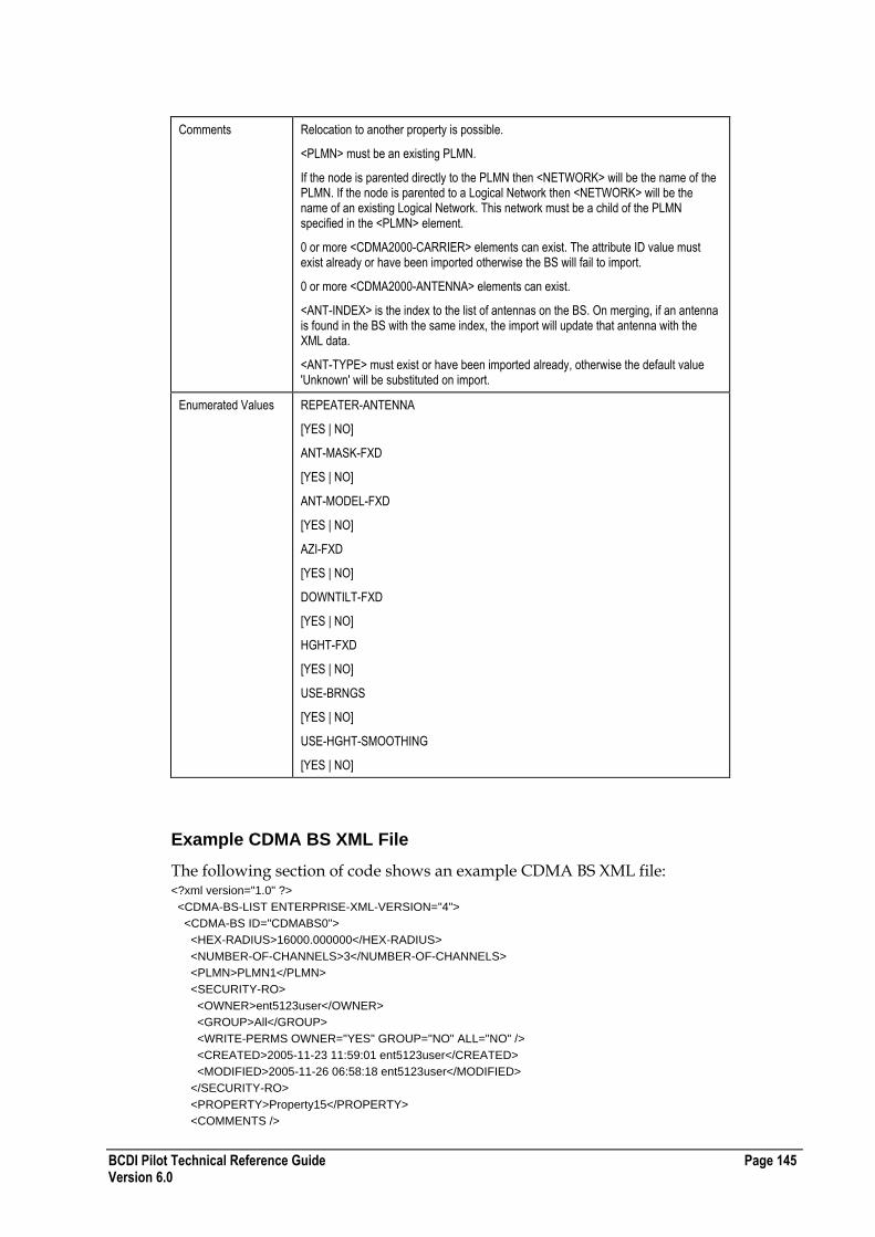
BCDI Pilot Technical Reference Guide Page 145 Version 6.0
Comments Relocation to another property is possible.
<PLMN> must be an existing PLMN.
If the node is parented directly to the PLMN then <NETWORK> will be the name of the PLMN. If the node is parented to a Logical Network then <NETWORK> will be the name of an existing Logical Network. This network must be a child of the PLMN specified in the <PLMN> element.
0 or more <CDMA2000-CARRIER> elements can exist. The attribute ID value must exist already or have been imported otherwise the BS will fail to import.
0 or more <CDMA2000-ANTENNA> elements can exist.
<ANT-INDEX> is the index to the list of antennas on the BS. On merging, if an antenna is found in the BS with the same index, the import will update that antenna with the XML data.
<ANT-TYPE> must exist or have been imported already, otherwise the default value 'Unknown' will be substituted on import.
Enumerated Values REPEATER-ANTENNA
[YES | NO]
ANT-MASK-FXD
[YES | NO]
ANT-MODEL-FXD
[YES | NO]
AZI-FXD
[YES | NO]
DOWNTILT-FXD
[YES | NO]
HGHT-FXD
[YES | NO]
USE-BRNGS
[YES | NO]
USE-HGHT-SMOOTHING
[YES | NO]
Example CDMA BS XML File
The following section of code shows an example CDMA BS XML file: <?xml version="1.0" ?>
<CDMA-BS-LIST ENTERPRISE-XML-VERSION="4">
<CDMA-BS ID="CDMABS0">
<HEX-RADIUS>16000.000000</HEX-RADIUS>
<NUMBER-OF-CHANNELS>3</NUMBER-OF-CHANNELS>
<PLMN>PLMN1</PLMN>
<SECURITY-RO>
<OWNER>ent5123user</OWNER>
<GROUP>All</GROUP>
<WRITE-PERMS OWNER="YES" GROUP="NO" ALL="NO" />
<CREATED>2005-11-23 11:59:01 ent5123user</CREATED>
<MODIFIED>2005-11-26 06:58:18 ent5123user</MODIFIED>
</SECURITY-RO>
<PROPERTY>Property15</PROPERTY>
<COMMENTS />
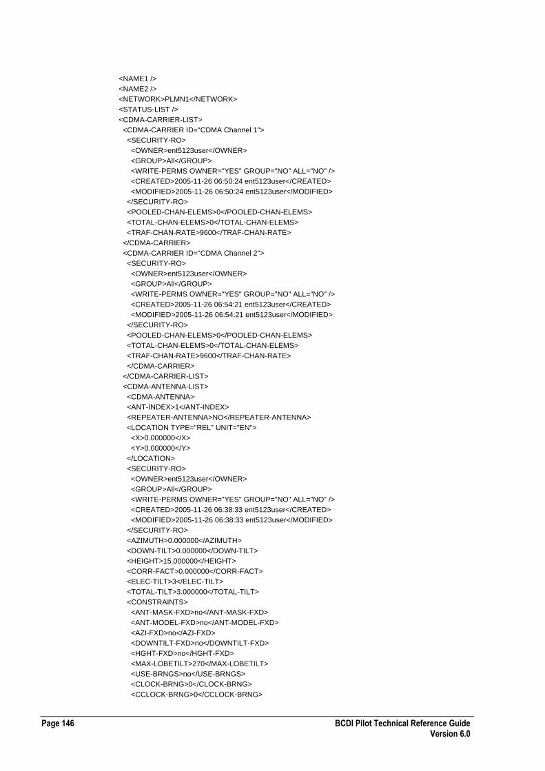
Page 146 BCDI Pilot Technical Reference Guide Version 6.0
<NAME1 />
<NAME2 />
<NETWORK>PLMN1</NETWORK>
<STATUS-LIST />
<CDMA-CARRIER-LIST>
<CDMA-CARRIER ID="CDMA Channel 1">
<SECURITY-RO>
<OWNER>ent5123user</OWNER>
<GROUP>All</GROUP>
<WRITE-PERMS OWNER="YES" GROUP="NO" ALL="NO" />
<CREATED>2005-11-26 06:50:24 ent5123user</CREATED>
<MODIFIED>2005-11-26 06:50:24 ent5123user</MODIFIED>
</SECURITY-RO>
<POOLED-CHAN-ELEMS>0</POOLED-CHAN-ELEMS>
<TOTAL-CHAN-ELEMS>0</TOTAL-CHAN-ELEMS>
<TRAF-CHAN-RATE>9600</TRAF-CHAN-RATE>
</CDMA-CARRIER>
<CDMA-CARRIER ID="CDMA Channel 2">
<SECURITY-RO>
<OWNER>ent5123user</OWNER>
<GROUP>All</GROUP>
<WRITE-PERMS OWNER="YES" GROUP="NO" ALL="NO" />
<CREATED>2005-11-26 06:54:21 ent5123user</CREATED>
<MODIFIED>2005-11-26 06:54:21 ent5123user</MODIFIED>
</SECURITY-RO>
<POOLED-CHAN-ELEMS>0</POOLED-CHAN-ELEMS>
<TOTAL-CHAN-ELEMS>0</TOTAL-CHAN-ELEMS>
<TRAF-CHAN-RATE>9600</TRAF-CHAN-RATE>
</CDMA-CARRIER>
</CDMA-CARRIER-LIST>
<CDMA-ANTENNA-LIST>
<CDMA-ANTENNA>
<ANT-INDEX>1</ANT-INDEX>
<REPEATER-ANTENNA>NO</REPEATER-ANTENNA>
<LOCATION TYPE="REL" UNIT="EN">
<X>0.000000</X>
<Y>0.000000</Y>
</LOCATION>
<SECURITY-RO>
<OWNER>ent5123user</OWNER>
<GROUP>All</GROUP>
<WRITE-PERMS OWNER="YES" GROUP="NO" ALL="NO" />
<CREATED>2005-11-26 06:38:33 ent5123user</CREATED>
<MODIFIED>2005-11-26 06:38:33 ent5123user</MODIFIED>
</SECURITY-RO>
<AZIMUTH>0.000000</AZIMUTH>
<DOWN-TILT>0.000000</DOWN-TILT>
<HEIGHT>15.000000</HEIGHT>
<CORR-FACT>0.000000</CORR-FACT>
<ELEC-TILT>3</ELEC-TILT>
<TOTAL-TILT>3.000000</TOTAL-TILT>
<CONSTRAINTS>
<ANT-MASK-FXD>no</ANT-MASK-FXD>
<ANT-MODEL-FXD>no</ANT-MODEL-FXD>
<AZI-FXD>no</AZI-FXD>
<DOWNTILT-FXD>no</DOWNTILT-FXD>
<HGHT-FXD>no</HGHT-FXD>
<MAX-LOBETILT>270</MAX-LOBETILT>
<USE-BRNGS>no</USE-BRNGS>
<CLOCK-BRNG>0</CLOCK-BRNG>
<CCLOCK-BRNG>0</CCLOCK-BRNG>

BCDI Pilot Technical Reference Guide Page 147 Version 6.0
</CONSTRAINTS>
<ANT-TYPE>60_4_13_SX_1800_R1\60_4_13_SX_1800_R1</ANT-TYPE>
<SHARED-ANT-ID />
<PRIMARY-MODEL-DATA>
<MODEL>Unknown</MODEL>
<RADIUS-METRES>0.000000</RADIUS-METRES>
<RADIUS-FT>0.000000</RADIUS-FT>
<RESOLUTION-METRES>0.000000</RESOLUTION-METRES>
<RESOLUTION-FT>0.000000</RESOLUTION-FT>
</PRIMARY-MODEL-DATA>
<SECONDARY-MODEL-DATA>
<MODEL>Unknown</MODEL>
<RADIUS-METRES>0.000000</RADIUS-METRES>
<RADIUS-FT>0.000000</RADIUS-FT>
<RESOLUTION-METRES>0.000000</RESOLUTION-METRES>
<RESOLUTION-FT>0.000000</RESOLUTION-FT>
</SECONDARY-MODEL-DATA>
<PRED-SYSTEM-INFO-RO>
<LOCATION TYPE="ABS" UNIT="EN">
<X>564025</X>
<Y>5450475</Y>
</LOCATION>
<ANTENNA-CRC64>11145571760223824810</ANTENNA-CRC64>
<PRIMARY-DATA>
<MODEL-CRC64 />
<ANT-DTM-USING-MT-RES>22.000000</ANT-DTM-USING-MT-RES>
<ANT-DTM-USING-IMP-RES>22.000000</ANT-DTM-USING-IMP-RES>
<USE-HGHT-SMOOTHING>no</USE-HGHT-SMOOTHING>
<PRED-FLAGS>0</PRED-FLAGS>
</PRIMARY-DATA>
<SECONDARY-DATA>
<MODEL-CRC64 />
<ANT-DTM-USING-MT-RES>22.000000</ANT-DTM-USING-MT-RES>
<ANT-DTM-USING-IMP-RES>22.000000</ANT-DTM-USING-IMP-RES>
<USE-HGHT-SMOOTHING>no</USE-HGHT-SMOOTHING>
<PRED-FLAGS>0</PRED-FLAGS>
</SECONDARY-DATA>
</PRED-SYSTEM-INFO-RO>
</CDMA-ANTENNA>
</CDMA-ANTENNA-LIST>
</CDMA-BS>
</CDMA-BS-LIST>
CDMA BS Sim Traffic XML File Format
The following table describes the XML file format for CDMA BS simulated traffic:
Required Tags CDMA2000-BS ID attribute
SERVICE ID attribute
SERVICE TYPE attribute
UL-BEARER ID attribute
DL-BEARER ID attribute

Page 148 BCDI Pilot Technical Reference Guide Version 6.0
Comments 0 or more <PRIMARY-TRAFFIC> elements can exist.
0 or more <HO-NODE> elements can exist.
<CELL-COUNT>, and <ACTIVITY> attributes are read only values.
A Service matching the <ID> and <TYPE> attributes must exits already or have been imported otherwise this traffic node will failed to import.
The Bearer <ID> attributes must exits already or have been imported otherwise this traffic node will failed to import.
If a traffic node failed to be imported, a message giving the cause of the failure can be found in the message log.
Enumerated Values TYPE
[Voice|RTD||PS]
Example CDMA BS Sim Traffic XML File
The following section of code shows an example CDMA simulated traffic XML file: <?xml version="1.0"?>
<CDMA-TRAFFIC-LIST ENTERPRISE-XML-VERSION="2">
<CDMA-BS ID="CDMABS2" CELL-COUNT="4">
<SECURITY-RO>
<OWNER>b</OWNER>
<GROUP>All</GROUP>
<WRITE-PERMS OWNER="YES" GROUP="YES" ALL="YES"/>
<CREATED>2004-05-12 15:54:57 b</CREATED>
<MODIFIED>2004-05-12 16:05:02 b</MODIFIED>
</SECURITY-RO>
<PRIMARY-TRAFFIC>
<SECURITY-RO>
<OWNER>b</OWNER>
<GROUP>All</GROUP>
<WRITE-PERMS OWNER="YES" GROUP="YES" ALL="YES"/>
<CREATED>2004-05-12 16:05:02 b</CREATED>
<MODIFIED>2004-05-12 16:05:02 b</MODIFIED>
</SECURITY-RO>
<SERVICE ID="CDMA Voice" TYPE="Voice"/>
<UL-BEARER ID="9.6kb/s Uplink" ACTIVITY="50.0"/>
<DL-BEARER ID="9.6kb/s Downlink" ACTIVITY="50.0"/>
<SUBSCRIBER MAX="28.0" MEAN="14.7" STD-DEV="3.7"/>
</PRIMARY-TRAFFIC>
<HO-TRAFFIC-LIST>
<HO-NODE ID="CDMABS1">
<SECURITY-RO>
<OWNER>b</OWNER>
<GROUP>All</GROUP>
<WRITE-PERMS OWNER="YES" GROUP="YES" ALL="YES"/>
<CREATED>2004-05-12 16:05:02 b</CREATED>
<MODIFIED>2004-05-12 16:05:02 b</MODIFIED>
</SECURITY-RO>
<SERVICE ID="CDMA Voice" TYPE="Voice"/>
<UL-BEARER ID="9.6kb/s Uplink" ACTIVITY="50.0"/>
<DL-BEARER ID="9.6kb/s Downlink" ACTIVITY="50.0"/>
<SUBSCRIBER MAX="8.0" MEAN="1.3" STD-DEV="1.1"/>
</HO-NODE>
</HO-TRAFFIC-LIST>
</CDMA-BS>
</CDMA-TRAFFIC-LIST>

BCDI Pilot Technical Reference Guide Page 149 Version 6.0
CDMA Sector XML File Format
The following table describes the XML file format for CDMA sectors:
Required Tags ID attribute
PARENT element
Comments 0 or more <CDMA2000-SECTORCARRIER> elements can exist.
0 or more <CDMA2000-FEEDER> elements can exist.
<ANT-INDEX> is the index into the list of antennas on the BS.
<CARRIER-NAME> must exist already or have been imported otherwise the sector will fail to import.
<FEEDER-TYPE> and <MHA-TYPE> must already exist, otherwise the default value 'Unknown' will be substituted on import.
Enumerated Values None
Example CDMA Sector XML File
The following section of code shows an example CDMA sector XML file: <?xml version="1.0" ?>
<CDMA-SECTOR-LIST ENTERPRISE-XML-VERSION="4">
<CDMA-SECTOR ID="CDMABS0A">
<SECURITY-RO>
<OWNER>ent5123user</OWNER>
<GROUP>All</GROUP>
<WRITE-PERMS OWNER="YES" GROUP="NO" ALL="NO" />
<CREATED>2005-11-26 07:02:15 ent5123user</CREATED>
<MODIFIED>2005-11-26 07:02:15 ent5123user</MODIFIED>
</SECURITY-RO>
<PARENT>CDMABS0</PARENT>
<PN-CODE>0</PN-CODE>
<NUMBER-OF-CHANNELS>4</NUMBER-OF-CHANNELS>
<STATUS-LIST />
<CDMA-SECTORCARRIER-LIST>
<CDMA-SECTORCARRIER>
<CARRIER-NAME>CDMA Channel 1</CARRIER-NAME>
<SECURITY-RO>
<OWNER>ent5123user</OWNER>
<GROUP>All</GROUP>
<WRITE-PERMS OWNER="YES" GROUP="NO" ALL="NO" />
<CREATED>2005-11-26 07:10:09 ent5123user</CREATED>
<MODIFIED>2005-11-26 07:10:09 ent5123user</MODIFIED>
</SECURITY-RO>
<RC-DL>RC1</RC-DL>
<DEDICATED-CHANS>0</DEDICATED-CHANS>
<HANDOFF-CHANS>0</HANDOFF-CHANS>
<NOISE-RISE>6.000000</NOISE-RISE>
<TX-LOSS>1.000000</TX-LOSS>
<RX-LOSS>1.000000</RX-LOSS>
<REC-NF>7.000000</REC-NF>
<EXCESS-NOISE-CHK>NO</EXCESS-NOISE-CHK>
<EXCESS-NOISE>-200.000000</EXCESS-NOISE>
<MIN-FUND-POW-PER-CHAN>21.000000</MIN-FUND-POW-PER-CHAN>
<MAX-FUND-POW-PER-CHAN>33.000000</MAX-FUND-POW-PER-CHAN>
<MIN-SUPPL-POW>21.000000</MIN-SUPPL-POW>
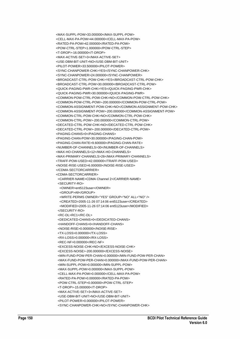
Page 150 BCDI Pilot Technical Reference Guide Version 6.0
<MAX-SUPPL-POW>33.000000</MAX-SUPPL-POW>
<CELL-MAX-PA-POW>44.000000</CELL-MAX-PA-POW>
<RATED-PA-POW>42.000000</RATED-PA-POW>
<POW-CTRL-STEP>1.000000</POW-CTRL-STEP>
<T-DROP>-16.000000</T-DROP>
<MAX-ACTIVE-SET>3</MAX-ACTIVE-SET>
<USE-DBM-BIT-UNIT>NO</USE-DBM-BIT-UNIT>
<PILOT-POWER>33.500000</PILOT-POWER>
<SYNC-CHANPOWER-CHK>YES</SYNC-CHANPOWER-CHK>
<SYNC-CHANPOWER>24.000000</SYNC-CHANPOWER>
<BROADCAST-CTRL-POW-CHK>YES</BROADCAST-CTRL-POW-CHK>
<BROADCAST-CTRL-POW>30.000000</BROADCAST-CTRL-POW>
<QUICK-PAGING-PWR-CHK>YES</QUICK-PAGING-PWR-CHK>
<QUICK-PAGING-PWR>30.000000</QUICK-PAGING-PWR>
<COMMON-POW-CTRL-POW-CHK>NO</COMMON-POW-CTRL-POW-CHK>
<COMMON-POW-CTRL-POW>-200.000000</COMMON-POW-CTRL-POW>
<COMMON-ASSIGNMENT-POW-CHK>NO</COMMON-ASSIGNMENT-POW-CHK>
<COMMON-ASSIGNMENT-POW>-200.000000</COMMON-ASSIGNMENT-POW>
<COMMON-CTRL-POW-CHK>NO</COMMON-CTRL-POW-CHK>
<COMMON-CTRL-POW>-200.000000</COMMON-CTRL-POW>
<DECATED-CTRL-POW-CHK>NO</DECATED-CTRL-POW-CHK>
<DECATED-CTRL-POW>-200.000000</DECATED-CTRL-POW>
<PAGING-CHANS>0</PAGING-CHANS>
<PAGING-CHAN-POW>30.000000</PAGING-CHAN-POW>
<PAGING-CHAN-RATE>9.600000</PAGING-CHAN-RATE>
<NUMBER-OF-CHANNELS>30</NUMBER-OF-CHANNELS>
<MAX-HO-CHANNELS>12</MAX-HO-CHANNELS>
<MAX-PRIMARY-CHANNELS>26</MAX-PRIMARY-CHANNELS>
<TRAFF-POW-USED>42.000000</TRAFF-POW-USED>
<NOISE-RISE-USED>6.000000</NOISE-RISE-USED>
</CDMA-SECTORCARRIER>
<CDMA-SECTORCARRIER>
<CARRIER-NAME>CDMA Channel 2</CARRIER-NAME>
<SECURITY-RO>
<OWNER>ent5123user</OWNER>
<GROUP>All</GROUP>
<WRITE-PERMS OWNER="YES" GROUP="NO" ALL="NO" />
<CREATED>2005-11-26 07:14:06 ent5123user</CREATED>
<MODIFIED>2005-11-26 07:14:06 ent5123user</MODIFIED>
</SECURITY-RO>
<RC-DL>RC1</RC-DL>
<DEDICATED-CHANS>0</DEDICATED-CHANS>
<HANDOFF-CHANS>0</HANDOFF-CHANS>
<NOISE-RISE>0.000000</NOISE-RISE>
<TX-LOSS>0.000000</TX-LOSS>
<RX-LOSS>0.000000</RX-LOSS>
<REC-NF>0.000000</REC-NF>
<EXCESS-NOISE-CHK>NO</EXCESS-NOISE-CHK>
<EXCESS-NOISE>-200.000000</EXCESS-NOISE>
<MIN-FUND-POW-PER-CHAN>0.000000</MIN-FUND-POW-PER-CHAN>
<MAX-FUND-POW-PER-CHAN>0.000000</MAX-FUND-POW-PER-CHAN>
<MIN-SUPPL-POW>0.000000</MIN-SUPPL-POW>
<MAX-SUPPL-POW>0.000000</MAX-SUPPL-POW>
<CELL-MAX-PA-POW>0.000000</CELL-MAX-PA-POW>
<RATED-PA-POW>0.000000</RATED-PA-POW>
<POW-CTRL-STEP>0.000000</POW-CTRL-STEP>
<T-DROP>-15.000000</T-DROP>
<MAX-ACTIVE-SET>3</MAX-ACTIVE-SET>
<USE-DBM-BIT-UNIT>NO</USE-DBM-BIT-UNIT>
<PILOT-POWER>0.000000</PILOT-POWER>
<SYNC-CHANPOWER-CHK>NO</SYNC-CHANPOWER-CHK>
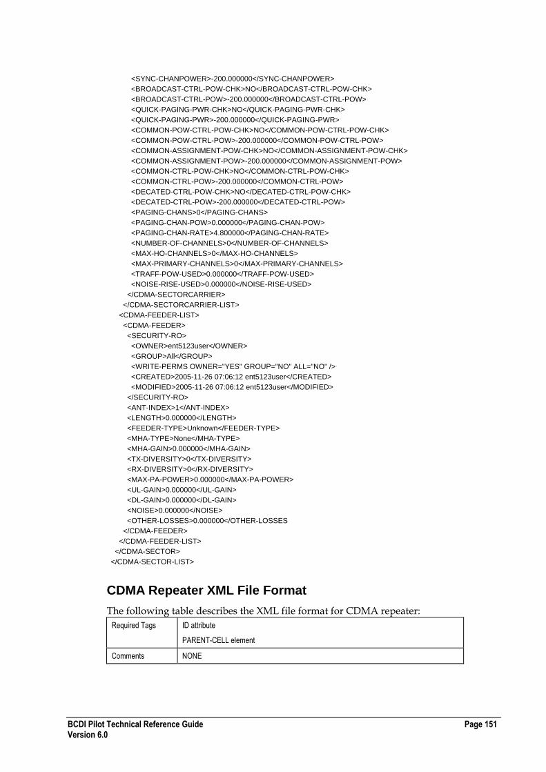
BCDI Pilot Technical Reference Guide Page 151 Version 6.0
<SYNC-CHANPOWER>-200.000000</SYNC-CHANPOWER>
<BROADCAST-CTRL-POW-CHK>NO</BROADCAST-CTRL-POW-CHK>
<BROADCAST-CTRL-POW>-200.000000</BROADCAST-CTRL-POW>
<QUICK-PAGING-PWR-CHK>NO</QUICK-PAGING-PWR-CHK>
<QUICK-PAGING-PWR>-200.000000</QUICK-PAGING-PWR>
<COMMON-POW-CTRL-POW-CHK>NO</COMMON-POW-CTRL-POW-CHK>
<COMMON-POW-CTRL-POW>-200.000000</COMMON-POW-CTRL-POW>
<COMMON-ASSIGNMENT-POW-CHK>NO</COMMON-ASSIGNMENT-POW-CHK>
<COMMON-ASSIGNMENT-POW>-200.000000</COMMON-ASSIGNMENT-POW>
<COMMON-CTRL-POW-CHK>NO</COMMON-CTRL-POW-CHK>
<COMMON-CTRL-POW>-200.000000</COMMON-CTRL-POW>
<DECATED-CTRL-POW-CHK>NO</DECATED-CTRL-POW-CHK>
<DECATED-CTRL-POW>-200.000000</DECATED-CTRL-POW>
<PAGING-CHANS>0</PAGING-CHANS>
<PAGING-CHAN-POW>0.000000</PAGING-CHAN-POW>
<PAGING-CHAN-RATE>4.800000</PAGING-CHAN-RATE>
<NUMBER-OF-CHANNELS>0</NUMBER-OF-CHANNELS>
<MAX-HO-CHANNELS>0</MAX-HO-CHANNELS>
<MAX-PRIMARY-CHANNELS>0</MAX-PRIMARY-CHANNELS>
<TRAFF-POW-USED>0.000000</TRAFF-POW-USED>
<NOISE-RISE-USED>0.000000</NOISE-RISE-USED>
</CDMA-SECTORCARRIER>
</CDMA-SECTORCARRIER-LIST>
<CDMA-FEEDER-LIST>
<CDMA-FEEDER>
<SECURITY-RO>
<OWNER>ent5123user</OWNER>
<GROUP>All</GROUP>
<WRITE-PERMS OWNER="YES" GROUP="NO" ALL="NO" />
<CREATED>2005-11-26 07:06:12 ent5123user</CREATED>
<MODIFIED>2005-11-26 07:06:12 ent5123user</MODIFIED>
</SECURITY-RO>
<ANT-INDEX>1</ANT-INDEX>
<LENGTH>0.000000</LENGTH>
<FEEDER-TYPE>Unknown</FEEDER-TYPE>
<MHA-TYPE>None</MHA-TYPE>
<MHA-GAIN>0.000000</MHA-GAIN>
<TX-DIVERSITY>0</TX-DIVERSITY>
<RX-DIVERSITY>0</RX-DIVERSITY>
<MAX-PA-POWER>0.000000</MAX-PA-POWER>
<UL-GAIN>0.000000</UL-GAIN>
<DL-GAIN>0.000000</DL-GAIN>
<NOISE>0.000000</NOISE>
<OTHER-LOSSES>0.000000</OTHER-LOSSES
</CDMA-FEEDER>
</CDMA-FEEDER-LIST>
</CDMA-SECTOR>
</CDMA-SECTOR-LIST>
CDMA Repeater XML File Format
The following table describes the XML file format for CDMA repeater:
Required Tags ID attribute
PARENT-CELL element
Comments NONE

Page 152 BCDI Pilot Technical Reference Guide Version 6.0
Enumerated Values ANT-MASK-FXD
[YES | NO]
ANT-MODEL-FXD
[YES | NO]
AZI-FXD
[YES | NO]
DOWNTILT-FXD
[YES | NO]
HGHT-FXD
[YES | NO]
USE-BRNGS
[YES | NO]
TX-DIVERSITY
[YES | NO]
RX-DIVERSITY
[YES | NO]
USE-HGHT-SMOOTHING
[YES | NO]
Example CDMA Repeater XML File
The following section of code shows an example CDMA Repeater XML file: <?xml version="1.0"?>
<CDMA-REPEATER-LIST ENTERPRISE-XML-VERSION="1">
<CDMA-REPEATER ID="CDMARepeater0">
<PARENT-CELL>CDMABS0A</PARENT-CELL>
<SECURITY-RO>
<OWNER>Administrator</OWNER>
<GROUP>All</GROUP>
<WRITE-PERMS OWNER="YES" GROUP="NO" ALL="NO"/>
<CREATED>2004-05-12 16:32:33 Administrator</CREATED>
<MODIFIED>2004-05-12 16:33:17 Administrator</MODIFIED>
</SECURITY-RO>
<PROPERTY>Property72</PROPERTY>
<COMMENTS/>
<NAME1 />
<NAME2 />
<NETWORK>PLMN1</NETWORK>
<STATUS-LIST />
<PLMN>PLMN1</PLMN>
<ANTENNA-RX>
<LOCATION TYPE="REL" UNIT="EN">
<X>0.000000</X>
<Y>0.000000</Y>
</LOCATION>
<SECURITY-RO>
<OWNER>Administrator</OWNER>
<GROUP>All</GROUP>
<WRITE-PERMS OWNER="YES" GROUP="NO" ALL="NO"/>
<CREATED>2004-05-12 16:32:34 Administrator</CREATED>
<MODIFIED>2004-05-12 16:33:17 Administrator</MODIFIED>
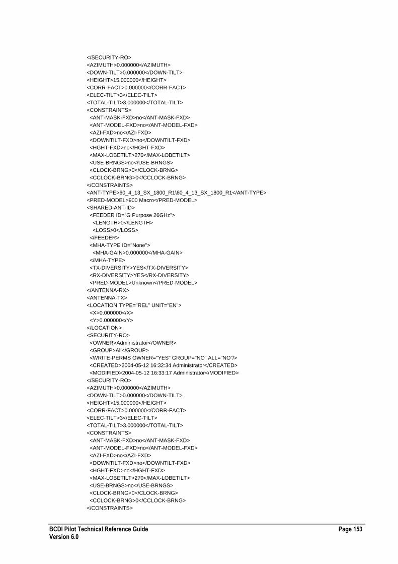
BCDI Pilot Technical Reference Guide Page 153 Version 6.0
</SECURITY-RO>
<AZIMUTH>0.000000</AZIMUTH>
<DOWN-TILT>0.000000</DOWN-TILT>
<HEIGHT>15.000000</HEIGHT>
<CORR-FACT>0.000000</CORR-FACT>
<ELEC-TILT>3</ELEC-TILT>
<TOTAL-TILT>3.000000</TOTAL-TILT>
<CONSTRAINTS>
<ANT-MASK-FXD>no</ANT-MASK-FXD>
<ANT-MODEL-FXD>no</ANT-MODEL-FXD>
<AZI-FXD>no</AZI-FXD>
<DOWNTILT-FXD>no</DOWNTILT-FXD>
<HGHT-FXD>no</HGHT-FXD>
<MAX-LOBETILT>270</MAX-LOBETILT>
<USE-BRNGS>no</USE-BRNGS>
<CLOCK-BRNG>0</CLOCK-BRNG>
<CCLOCK-BRNG>0</CCLOCK-BRNG>
</CONSTRAINTS>
<ANT-TYPE>60_4_13_SX_1800_R1\60_4_13_SX_1800_R1</ANT-TYPE>
<PRED-MODEL>900 Macro</PRED-MODEL>
<SHARED-ANT-ID>
<FEEDER ID="G Purpose 26GHz">
<LENGTH>0</LENGTH>
<LOSS>0</LOSS>
</FEEDER>
<MHA-TYPE ID="None">
<MHA-GAIN>0.000000</MHA-GAIN>
</MHA-TYPE>
<TX-DIVERSITY>YES</TX-DIVERSITY>
<RX-DIVERSITY>YES</RX-DIVERSITY>
<PRED-MODEL>Unknown</PRED-MODEL>
</ANTENNA-RX>
<ANTENNA-TX>
<LOCATION TYPE="REL" UNIT="EN">
<X>0.000000</X>
<Y>0.000000</Y>
</LOCATION>
<SECURITY-RO>
<OWNER>Administrator</OWNER>
<GROUP>All</GROUP>
<WRITE-PERMS OWNER="YES" GROUP="NO" ALL="NO"/>
<CREATED>2004-05-12 16:32:34 Administrator</CREATED>
<MODIFIED>2004-05-12 16:33:17 Administrator</MODIFIED>
</SECURITY-RO>
<AZIMUTH>0.000000</AZIMUTH>
<DOWN-TILT>0.000000</DOWN-TILT>
<HEIGHT>15.000000</HEIGHT>
<CORR-FACT>0.000000</CORR-FACT>
<ELEC-TILT>3</ELEC-TILT>
<TOTAL-TILT>3.000000</TOTAL-TILT>
<CONSTRAINTS>
<ANT-MASK-FXD>no</ANT-MASK-FXD>
<ANT-MODEL-FXD>no</ANT-MODEL-FXD>
<AZI-FXD>no</AZI-FXD>
<DOWNTILT-FXD>no</DOWNTILT-FXD>
<HGHT-FXD>no</HGHT-FXD>
<MAX-LOBETILT>270</MAX-LOBETILT>
<USE-BRNGS>no</USE-BRNGS>
<CLOCK-BRNG>0</CLOCK-BRNG>
<CCLOCK-BRNG>0</CCLOCK-BRNG>
</CONSTRAINTS>
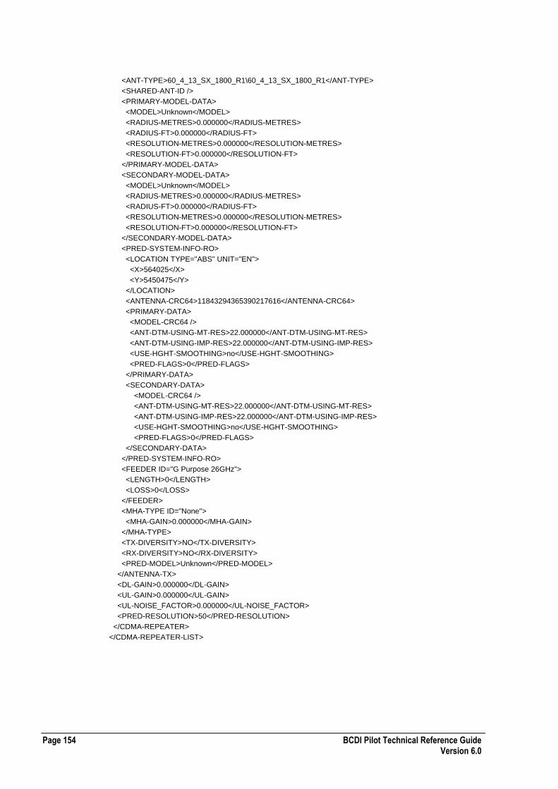
Page 154 BCDI Pilot Technical Reference Guide Version 6.0
<ANT-TYPE>60_4_13_SX_1800_R1\60_4_13_SX_1800_R1</ANT-TYPE>
<SHARED-ANT-ID />
<PRIMARY-MODEL-DATA>
<MODEL>Unknown</MODEL>
<RADIUS-METRES>0.000000</RADIUS-METRES>
<RADIUS-FT>0.000000</RADIUS-FT>
<RESOLUTION-METRES>0.000000</RESOLUTION-METRES>
<RESOLUTION-FT>0.000000</RESOLUTION-FT>
</PRIMARY-MODEL-DATA>
<SECONDARY-MODEL-DATA>
<MODEL>Unknown</MODEL>
<RADIUS-METRES>0.000000</RADIUS-METRES>
<RADIUS-FT>0.000000</RADIUS-FT>
<RESOLUTION-METRES>0.000000</RESOLUTION-METRES>
<RESOLUTION-FT>0.000000</RESOLUTION-FT>
</SECONDARY-MODEL-DATA>
<PRED-SYSTEM-INFO-RO>
<LOCATION TYPE="ABS" UNIT="EN">
<X>564025</X>
<Y>5450475</Y>
</LOCATION>
<ANTENNA-CRC64>11843294365390217616</ANTENNA-CRC64>
<PRIMARY-DATA>
<MODEL-CRC64 />
<ANT-DTM-USING-MT-RES>22.000000</ANT-DTM-USING-MT-RES>
<ANT-DTM-USING-IMP-RES>22.000000</ANT-DTM-USING-IMP-RES>
<USE-HGHT-SMOOTHING>no</USE-HGHT-SMOOTHING>
<PRED-FLAGS>0</PRED-FLAGS>
</PRIMARY-DATA>
<SECONDARY-DATA>
<MODEL-CRC64 />
<ANT-DTM-USING-MT-RES>22.000000</ANT-DTM-USING-MT-RES>
<ANT-DTM-USING-IMP-RES>22.000000</ANT-DTM-USING-IMP-RES>
<USE-HGHT-SMOOTHING>no</USE-HGHT-SMOOTHING>
<PRED-FLAGS>0</PRED-FLAGS>
</SECONDARY-DATA>
</PRED-SYSTEM-INFO-RO>
<FEEDER ID="G Purpose 26GHz">
<LENGTH>0</LENGTH>
<LOSS>0</LOSS>
</FEEDER>
<MHA-TYPE ID="None">
<MHA-GAIN>0.000000</MHA-GAIN>
</MHA-TYPE>
<TX-DIVERSITY>NO</TX-DIVERSITY>
<RX-DIVERSITY>NO</RX-DIVERSITY>
<PRED-MODEL>Unknown</PRED-MODEL>
</ANTENNA-TX>
<DL-GAIN>0.000000</DL-GAIN>
<UL-GAIN>0.000000</UL-GAIN>
<UL-NOISE_FACTOR>0.000000</UL-NOISE_FACTOR>
<PRED-RESOLUTION>50</PRED-RESOLUTION>
</CDMA-REPEATER>
</CDMA-REPEATER-LIST>
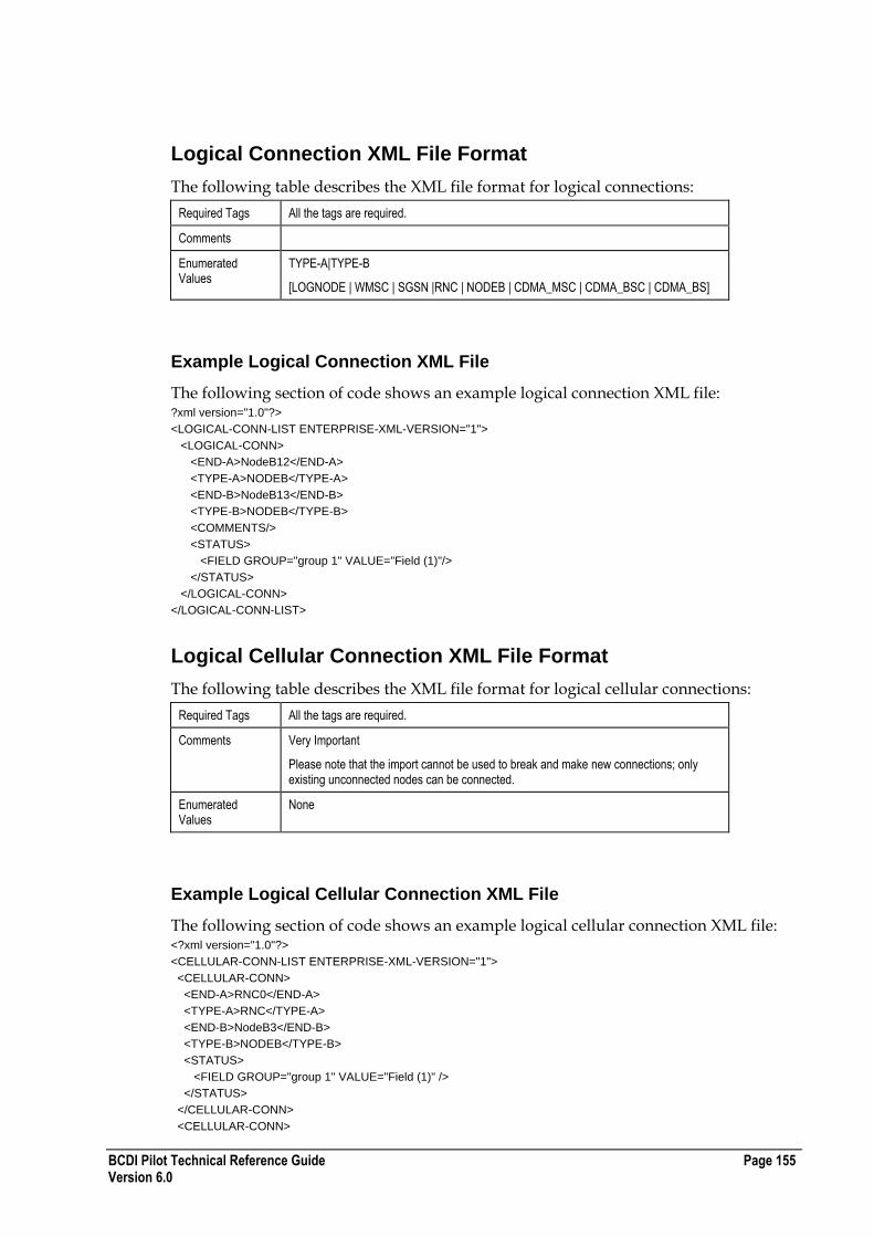
BCDI Pilot Technical Reference Guide Page 155 Version 6.0
Logical Connection XML File Format
The following table describes the XML file format for logical connections:
Required Tags All the tags are required.
Comments
Enumerated Values
TYPE-A|TYPE-B
[LOGNODE | WMSC | SGSN |RNC | NODEB | CDMA_MSC | CDMA_BSC | CDMA_BS]
Example Logical Connection XML File
The following section of code shows an example logical connection XML file: ?xml version="1.0"?>
<LOGICAL-CONN-LIST ENTERPRISE-XML-VERSION="1">
<LOGICAL-CONN>
<END-A>NodeB12</END-A>
<TYPE-A>NODEB</TYPE-A>
<END-B>NodeB13</END-B>
<TYPE-B>NODEB</TYPE-B>
<COMMENTS/>
<STATUS>
<FIELD GROUP="group 1" VALUE="Field (1)"/>
</STATUS>
</LOGICAL-CONN>
</LOGICAL-CONN-LIST>
Logical Cellular Connection XML File Format
The following table describes the XML file format for logical cellular connections:
Required Tags All the tags are required.
Comments Very Important
Please note that the import cannot be used to break and make new connections; only existing unconnected nodes can be connected.
Enumerated Values
None
Example Logical Cellular Connection XML File
The following section of code shows an example logical cellular connection XML file: <?xml version="1.0"?>
<CELLULAR-CONN-LIST ENTERPRISE-XML-VERSION="1">
<CELLULAR-CONN>
<END-A>RNC0</END-A>
<TYPE-A>RNC</TYPE-A>
<END-B>NodeB3</END-B>
<TYPE-B>NODEB</TYPE-B>
<STATUS>
<FIELD GROUP="group 1" VALUE="Field (1)" />
</STATUS>
</CELLULAR-CONN>
<CELLULAR-CONN>
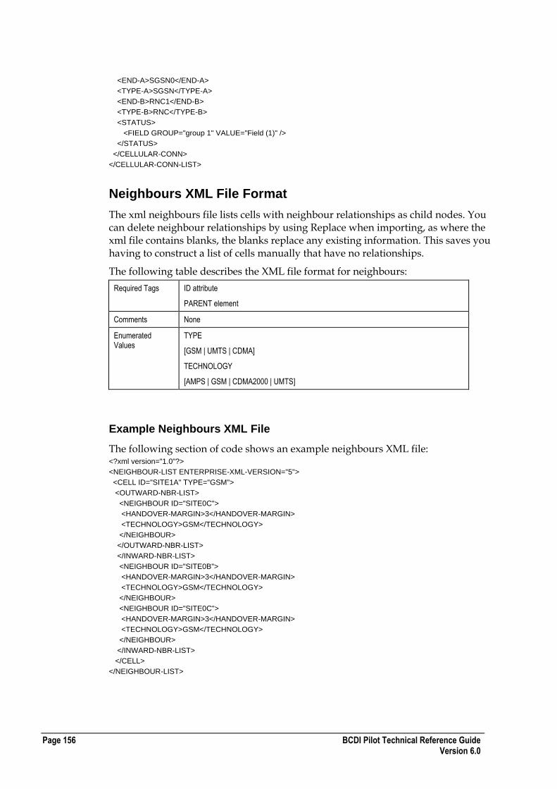
Page 156 BCDI Pilot Technical Reference Guide Version 6.0
<END-A>SGSN0</END-A>
<TYPE-A>SGSN</TYPE-A>
<END-B>RNC1</END-B>
<TYPE-B>RNC</TYPE-B>
<STATUS>
<FIELD GROUP="group 1" VALUE="Field (1)" />
</STATUS>
</CELLULAR-CONN>
</CELLULAR-CONN-LIST>
Neighbours XML File Format
The xml neighbours file lists cells with neighbour relationships as child nodes. You can delete neighbour relationships by using Replace when importing, as where the xml file contains blanks, the blanks replace any existing information. This saves you having to construct a list of cells manually that have no relationships.
The following table describes the XML file format for neighbours:
Required Tags ID attribute
PARENT element
Comments None
Enumerated Values
TYPE
[GSM | UMTS | CDMA]
TECHNOLOGY
[AMPS | GSM | CDMA2000 | UMTS]
Example Neighbours XML File
The following section of code shows an example neighbours XML file: <?xml version="1.0"?>
<NEIGHBOUR-LIST ENTERPRISE-XML-VERSION="5">
<CELL ID="SITE1A" TYPE="GSM">
<OUTWARD-NBR-LIST>
<NEIGHBOUR ID="SITE0C">
<HANDOVER-MARGIN>3</HANDOVER-MARGIN>
<TECHNOLOGY>GSM</TECHNOLOGY>
</NEIGHBOUR>
</OUTWARD-NBR-LIST>
</INWARD-NBR-LIST>
<NEIGHBOUR ID="SITE0B">
<HANDOVER-MARGIN>3</HANDOVER-MARGIN>
<TECHNOLOGY>GSM</TECHNOLOGY>
</NEIGHBOUR>
<NEIGHBOUR ID="SITE0C">
<HANDOVER-MARGIN>3</HANDOVER-MARGIN>
<TECHNOLOGY>GSM</TECHNOLOGY>
</NEIGHBOUR>
</INWARD-NBR-LIST>
</CELL>
</NEIGHBOUR-LIST>

BCDI Pilot Technical Reference Guide Page 157 Version 6.0
LCSE Neighbours XML File Format
The following table describes the XML file format for LCSE neighbours:
Required Tags ID attribute
PARENT element
Comments None
Enumerated values TYPE
[GSM | UMTS | CDMA]
TECHNOLOGY
[LCSEGSM | LCSEUMTS | LCSECDMA]
Example LCSE Neighbours File
The following section of code shows an example LCSE neighbours XML file: <?xml version="1.0"?>
<LCSE-NEIGHBOUR-LIST ENTERPRISE-XML-VERSION="4">
<CELL ID="SITE1A" TYPE="GSM">
<OUTWARD-NBR-LIST>
<LCSE-NEIGHBOUR ID="SITE0B">
<HANDOVER-MARGIN>0</HANDOVER-MARGIN>
<TECHNOLOGY>LCSEGSM</TECHNOLOGY>
</LCSE-NEIGHBOUR>
<LCSE-NEIGHBOUR ID="SITE0C">
<HANDOVER-MARGIN>0</HANDOVER-MARGIN>
<TECHNOLOGY>LCSEGSM</TECHNOLOGY>
</LCSE-NEIGHBOUR>
</OUTWARD-NBR-LIST>
<INWARD-NBR-LIST>
<LCSE-NEIGHBOUR ID="SITE0C">
<HANDOVER-MARGIN>0</HANDOVER-MARGIN>
<TECHNOLOGY>LCSEGSM</TECHNOLOGY>
</LCSE-NEIGHBOUR>
<LCSE-NEIGHBOUR ID="SITE0B
<HANDOVER-MARGIN>0</HANDOVER-MARGIN>
<TECHNOLOGY>LCSEGSM</TECHNOLOGY>
</LCSE-NEIGHBOUR>
</INWARD-NBR-LIST>
</CELL>
</LCSE-NEIGHBOUR-LIST>
WiMAX Node XML File Format
The following table describes the XML file format for WiMAX Nodes:
Required Tags ID attribute
PLMN element
NETWORK element
PROPERTY element

Page 158 BCDI Pilot Technical Reference Guide Version 6.0
Comments Relocation to another Property is possible.
<PLMN> must be an existing PLMN.
If the node is parented directly to the PLMN then <NETWORK> will be the name of the PLMN. If the node is parented to a Logical Network then <NETWORK> will be the name of an existing Logical Network. This network must be a child of the PLMN specified in the <PLMN> element.
<NODEBID>
9 Digits maximum each digit 0-9
In order to import the carriers on the node the carrier name must exist or have been previously imported.
In order to import the antennas correctly the antenna must exist and to connect the propagation model this must exist also.
The sample XML file shows resources allocated to the node, Carrier and Antenna.
Enumerated Values DL-PUSC-SUBCHAN-POOL-METHOD
[Node-Carrier | Sector]
DL-FUSC-SUBCHAN-POOL-METHOD
[Node-Carrier | Sector]
UL-PUSC-SUBCHAN-POOL-METHOD
[Node-Carrier | Sector]
REPEATER-ANTENNA
[YES | NO]
ANT-MASK-FXD
[YES | NO]
ANT-MODEL-FXD
[YES | NO]
AZI-FXD
[YES | NO]
DOWNTILT-FXD
[YES | NO]
HGHT-FXD
[YES | NO]
USE-BRNGS
[YES | NO]
USE-HGHT-SMOOTHING
[YES | NO]
Important : There is a separate file format for UMTS Nodes. For more information, see UMTS Node XML File Format on page 130.
Example WiMAX Node XML File
The following section of code shows an example WiMAX Node XML file: <?xml version="1.0">
<WiMAX-NODE-LIST ENTERPRISE-XML-VERSION="1">
<WiMAX-NODE ID="NodeW">
<HEX-RADIUS>1000.000000</HEX-RADIUS>

BCDI Pilot Technical Reference Guide Page 159 Version 6.0
<NODEBID>-1<NODEBID>
<TECHNOLOGY>WiMAX</TECHNOLOGY>
<NODEBTYPE>Unknown</NODEBTYPE>
<PLMN>PLMN0</PLMN>
<MCC>000</MCC>
<MNC>000</MNC>
<SECURITY-RO>
<OWNER>Administrator</OWNER>
<GROUP>All</GROUP>
<WRITE-PERMS OWNER="YES" GROUP="NO" ALL="NO"/>
<CREATED>2006-06-06 14:35:02 Administrator</CREATED>
<MODIFIED>2006-06-06 14:35:02 Administrator</MODIFIED>
</SECURITY-RO>
<PROPERTY>Property73</PROPERTY>
<COMMENTS />
<NAME1 />
<NAME2 />
<NETWORK>PLMN0</NETWORK>
<STATUS-LIST />
<RES1ULTOT>10000</RES1ULTOT>
<RES1DLTOT>10000</RES1DLTOT>
<RES1ULPRI>5000</RES1ULPRI>
<RES1DLPRI>5000</RES1DLPRI>
<RES1ULHO>5000</RES1ULHO>
<RES1DLHO>5000</RES1DLHO>
<WiMAX-CARRIER-LIST>
<WiMAX-CARRIER ID="Carrier1" />
<SECURITY-RO>
<OWNER>demouser</OWNER>
<GROUP>All</GROUP>
<WRITE-PERMS OWNER="YES" GROUP="NO" ALL="NO"/>
<CREATED>2007-03-27 11:40:07 demouser</CREATED>
<MODIFIED>2007-03-27 11:41:08 demouser</MODIFIED>
</SECURITY-RO>
<DL-PUSC-SUBCHAN-POOL-METHOD>Node-Carrier</DL-PUSC-SUBCHAN-POOL-METHOD>
<DL-FUSC-SUBCHAN-POOL-METHOD>Sector</DL-FUSC-SUBCHAN-POOL-METHOD>
<UL-PUSC-SUBCHAN-POOL-METHOD>Node-Carrier</UL-PUSC-SUBCHAN-POOL-METHOD>
</WiMAX-CARRIER>
<WiMAX-CARRIER ID="Carrier2" />
<SECURITY-RO>
<OWNER>demouser</OWNER>
<GROUP>All</GROUP>
<WRITE-PERMS OWNER="YES" GROUP="NO" ALL="NO"/>
<CREATED>2007-03-27 11:40:07 demouser</CREATED>
<MODIFIED>2007-03-27 11:41:08 demouser</MODIFIED>
</SECURITY-RO>
<DL-PUSC-SUBCHAN-POOL-METHOD>Node-Carrier</DL-PUSC-SUBCHAN-POOL-METHOD>
<DL-FUSC-SUBCHAN-POOL-METHOD>Sector</DL-FUSC-SUBCHAN-POOL-METHOD>
<UL-PUSC-SUBCHAN-POOL-METHOD>Node-Carrier</UL-PUSC-SUBCHAN-POOL-METHOD>
</WiMAX-CARRIER>
<WiMAX-CARRIER ID="Carrier3" />
<SECURITY-RO>
<OWNER>demouser</OWNER>
<GROUP>All</GROUP>
<WRITE-PERMS OWNER="YES" GROUP="NO" ALL="NO"/>
<CREATED>2007-03-27 11:40:07 demouser</CREATED>
<MODIFIED>2007-03-27 11:41:08 demouser</MODIFIED>
</SECURITY-RO>
<DL-PUSC-SUBCHAN-POOL-METHOD>Node-Carrier</DL-PUSC-SUBCHAN-POOL-METHOD>
<DL-FUSC-SUBCHAN-POOL-METHOD>Sector</DL-FUSC-SUBCHAN-POOL-METHOD>
<UL-PUSC-SUBCHAN-POOL-METHOD>Node-Carrier</UL-PUSC-SUBCHAN-POOL-METHOD>

Page 160 BCDI Pilot Technical Reference Guide Version 6.0
</WiMAX-CARRIER>
</WiMAX-CARRIER-LIST>
<WiMAX-ANTENNA-LIST>
<WiMAX-ANTENNA>
<ANT-INDEX>0</ANT-INDEX>
<ANT-UL-GAIN-CORRECTION-FACTOR>0.000000</ANT-UL-GAIN-CORRECTION-FACTOR>
<REPEATER-ANTENNA>NO</REPEATER-ANTENNA>
<LOCATION TYPE="REL" UNIT="EN">
<X>0.000000</X>
<Y>0.000000</Y>
</LOCATION>
<SECURITY-RO>
<OWNER>ent6023user</OWNER>
<GROUP>All</GROUP>
<WRITE-PERMS OWNER="YES" GROUP="NO" ALL="NO" />
<CREATED>2007-07-02 16:23:25 ent6023user</CREATED>
<MODIFIED>2007-07-02 16:23:25 ent6023user</MODIFIED>
</SECURITY-RO>
<AZIMUTH>0.000000</AZIMUTH>
<DOWN-TILT>0.000000</DOWN-TILT>
<HEIGHT>15.000000</HEIGHT>
<CORR-FACT>0.000000</CORR-FACT>
<CONSTRAINTS>
<ANT-MASK-FXD>no</ANT-MASK-FXD>
<ANT-MODEL-FXD>no</ANT-MODEL-FXD>
<AZI-FXD>no</AZI-FXD>
<DOWNTILT-FXD>no</DOWNTILT-FXD>
<HGHT-FXD>no</HGHT-FXD>
<MAX-LOBETILT>270</MAX-LOBETILT>
<USE-BRNGS>no</USE-BRNGS>
<CLOCK-BRNG>0</CLOCK-BRNG>
<CCLOCK-BRNG>0</CCLOCK-BRNG>
</CONSTRAINTS>
<ANT-TYPE>Unknown</ANT-TYPE>
<SHARED-ANT-ID />
<PRIMARY-MODEL-DATA>
<MODEL>Unknown</MODEL>
<RADIUS-METRES>0.000000</RADIUS-METRES>
<RADIUS-FT>0.000000</RADIUS-FT>
<RESOLUTION-METRES>0.000000</RESOLUTION-METRES>
<RESOLUTION-FT>0.000000</RESOLUTION-FT>
</PRIMARY-MODEL-DATA>
<SECONDARY-MODEL-DATA>
<MODEL>Unknown</MODEL>
<RADIUS-METRES>0.000000</RADIUS-METRES>
<RADIUS-FT>0.000000</RADIUS-FT>
<RESOLUTION-METRES>0.000000</RESOLUTION-METRES>
<RESOLUTION-FT>0.000000</RESOLUTION-FT>
</SECONDARY-MODEL-DATA>
<PRED-SYSTEM-INFO-RO>
<LOCATION TYPE="ABS" UNIT="EN">
<X>564025</X>
<Y>5450475</Y>
</LOCATION>
<ANTENNA-CRC64>1293530900947749955</ANTENNA-CRC64>
<PRIMARY-DATA>
<MODEL-CRC64 />
<ANT-DTM-USING-MT-RES>22.000000</ANT-DTM-USING-MT-RES>
<ANT-DTM-USING-IMP-RES>22.000000</ANT-DTM-USING-IMP-RES>
<USE-HGHT-SMOOTHING>no</USE-HGHT-SMOOTHING>
<PRED-FLAGS>0</PRED-FLAGS>

BCDI Pilot Technical Reference Guide Page 161 Version 6.0
</PRIMARY-DATA>
<SECONDARY-DATA>
<MODEL-CRC64 />
<ANT-DTM-USING-MT-RES>22.000000</ANT-DTM-USING-MT-RES>
<ANT-DTM-USING-IMP-RES>22.000000</ANT-DTM-USING-IMP-RES>
<USE-HGHT-SMOOTHING>no</USE-HGHT-SMOOTHING>
<PRED-FLAGS>0</PRED-FLAGS>
</SECONDARY-DATA>
</PRED-SYSTEM-INFO-RO>
</WiMAX-ANTENNA>
</WiMAX-ANTENNA-LIST>
</WiMAX-NODE>
</WiMAX-NODE-LIST>
WiMAX Cell XML File Format
The following table describes the XML file format for WiMAX cells:
Required Tags ID attribute
PARENT The node this cell is connected to
Comments LOCALCELLID Maximum 9 digits each digit 0-9
LAC Maximum 5 digits each digit 0-9
RAC Maximum 3 digits each digit 0-9
SAC Maximum 3 digits each digit 0-9
LCR Unused
UMTS-CELL-FEEDER
ANT-INDEX must be a valid index to the Parent Node antenna.
FEEDER-TYPE and MHA-TYPE must exist already or have been imported otherwise these equipment types will not be set.
Enumerated Values MULTIPATH-TYPE
[ Heavy Multipath | Light Multipath | Mixed ]
COVERAGE-TYPE
[ Outdoor | Indoor ]
HSDPA-LINKPOWER
[True | False]
Example WiMAX Cell XML File
The following section of code shows an example WiMAX cell XML file: <?xml version="1.0" ?>
<WiMAX-CELL-LIST ENTERPRISE-XML-VERSION="1">
<WiMAX-CELL ID="Node0A" HSDPA-SUPPORTED="0">
<SECURITY-RO>
<OWNER>Administrator</OWNER>
<GROUP>All</GROUP>
<WRITE-PERMS OWNER="YES" GROUP="NO" ALL="NO" />
<CREATED>2006-06-06 14:35:06 Administrator</CREATED>
<MODIFIED>2006-06-06 14:35:06 Administrator</MODIFIED>
</SECURITY-RO>
<PARENT>Node0</PARENT>
<UMTSCELLNAME />
<TECHNOLOGY-RO>WiMAX</TECHNOLOGY-RO>
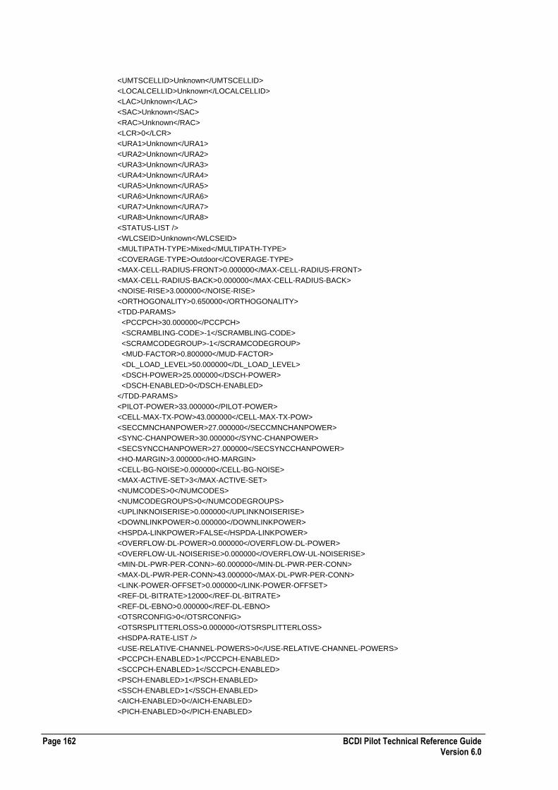
Page 162 BCDI Pilot Technical Reference Guide Version 6.0
<UMTSCELLID>Unknown</UMTSCELLID>
<LOCALCELLID>Unknown</LOCALCELLID>
<LAC>Unknown</LAC>
<SAC>Unknown</SAC>
<RAC>Unknown</RAC>
<LCR>0</LCR>
<URA1>Unknown</URA1>
<URA2>Unknown</URA2>
<URA3>Unknown</URA3>
<URA4>Unknown</URA4>
<URA5>Unknown</URA5>
<URA6>Unknown</URA6>
<URA7>Unknown</URA7>
<URA8>Unknown</URA8>
<STATUS-LIST />
<WLCSEID>Unknown</WLCSEID>
<MULTIPATH-TYPE>Mixed</MULTIPATH-TYPE>
<COVERAGE-TYPE>Outdoor</COVERAGE-TYPE>
<MAX-CELL-RADIUS-FRONT>0.000000</MAX-CELL-RADIUS-FRONT>
<MAX-CELL-RADIUS-BACK>0.000000</MAX-CELL-RADIUS-BACK>
<NOISE-RISE>3.000000</NOISE-RISE>
<ORTHOGONALITY>0.650000</ORTHOGONALITY>
<TDD-PARAMS>
<PCCPCH>30.000000</PCCPCH>
<SCRAMBLING-CODE>-1</SCRAMBLING-CODE>
<SCRAMCODEGROUP>-1</SCRAMCODEGROUP>
<MUD-FACTOR>0.800000</MUD-FACTOR>
<DL_LOAD_LEVEL>50.000000</DL_LOAD_LEVEL>
<DSCH-POWER>25.000000</DSCH-POWER>
<DSCH-ENABLED>0</DSCH-ENABLED>
</TDD-PARAMS>
<PILOT-POWER>33.000000</PILOT-POWER>
<CELL-MAX-TX-POW>43.000000</CELL-MAX-TX-POW>
<SECCMNCHANPOWER>27.000000</SECCMNCHANPOWER>
<SYNC-CHANPOWER>30.000000</SYNC-CHANPOWER>
<SECSYNCCHANPOWER>27.000000</SECSYNCCHANPOWER>
<HO-MARGIN>3.000000</HO-MARGIN>
<CELL-BG-NOISE>0.000000</CELL-BG-NOISE>
<MAX-ACTIVE-SET>3</MAX-ACTIVE-SET>
<NUMCODES>0</NUMCODES>
<NUMCODEGROUPS>0</NUMCODEGROUPS>
<UPLINKNOISERISE>0.000000</UPLINKNOISERISE>
<DOWNLINKPOWER>0.000000</DOWNLINKPOWER>
<HSPDA-LINKPOWER>FALSE</HSPDA-LINKPOWER>
<OVERFLOW-DL-POWER>0.000000</OVERFLOW-DL-POWER>
<OVERFLOW-UL-NOISERISE>0.000000</OVERFLOW-UL-NOISERISE>
<MIN-DL-PWR-PER-CONN>-60.000000</MIN-DL-PWR-PER-CONN>
<MAX-DL-PWR-PER-CONN>43.000000</MAX-DL-PWR-PER-CONN>
<LINK-POWER-OFFSET>0.000000</LINK-POWER-OFFSET>
<REF-DL-BITRATE>12000</REF-DL-BITRATE>
<REF-DL-EBNO>0.000000</REF-DL-EBNO>
<OTSRCONFIG>0</OTSRCONFIG>
<OTSRSPLITTERLOSS>0.000000</OTSRSPLITTERLOSS>
<HSDPA-RATE-LIST />
<USE-RELATIVE-CHANNEL-POWERS>0</USE-RELATIVE-CHANNEL-POWERS>
<PCCPCH-ENABLED>1</PCCPCH-ENABLED>
<SCCPCH-ENABLED>1</SCCPCH-ENABLED>
<PSCH-ENABLED>1</PSCH-ENABLED>
<SSCH-ENABLED>1</SSCH-ENABLED>
<AICH-ENABLED>0</AICH-ENABLED>
<PICH-ENABLED>0</PICH-ENABLED>

BCDI Pilot Technical Reference Guide Page 163 Version 6.0
<MAX-HSDPA-POWER>30.000000</MAX-HSDPA-POWER>
<AICH-POWER>25.000000</AICH-POWER>
<PICH-POWER>25.000000</PICH-POWER>
<AICH-ACTIVITY>0.800000</AICH-ACTIVITY>
<PICH-ACTIVITY>0.960000</PICH-ACTIVITY>
<SCCPCH-ACTIVITY>1.000000</SCCPCH-ACTIVITY>
<RX-SENSITIVITY>-98.000000</RX-SENSITIVITY>
<CONTROL-POWER>-200.000000</CONTROL-POWER>
<CONTROL-ACTIVITY>0.000000</CONTROL-ACTIVITY>
<WiMAX-TX-POWER>32.000000</WiMAX-TX-POWER>
<WiMAX-TX-POWER>32.000000</WiMAX-TX-POWER>
<SUBCHANNELS>
<SIXTEENTH>0</SIXTEENTH>
<EIGHTH>0</EIGHTH>
<QUARTER>0</QUARTER>
<HALF>0</HALF>
</SUBCHANNELS>
<WiMAX-CELL-FEEDER-LIST>
<WiMAX-CELL-FEEDER>
<SECURITY-RO>
<OWNER>ent36user</OWNER>
<GROUP>All</GROUP>
<WRITE-PERMS OWNER="YES" GROUP="NO" ALL="NO" />
<CREATED>2007-07-26 15:02:34 ent36user</CREATED>
<MODIFIED>2007-07-26 15:02:34 ent36user</MODIFIED>
</SECURITY-RO>
<ANT-INDEX>1</ANT-INDEX>
<ANT-INFO-RO>
<AZIMUTH>0.000000</AZIMUTH>
<DOWN-TILT>0.000000</DOWN-TILT>
<HEIGHT>15.000000</HEIGHT>
<PRIMARY-MODEL-DATA>
<MODEL>Unknown</MODEL>
<RADIUS-METRES>10.000000</RADIUS-METRES>
<RADIUS-FT>6.210000</RADIUS-FT>
<RESOLUTION-METRES>50.000000</RESOLUTION-METRES>
<RESOLUTION-FT>164.039993</RESOLUTION-FT>
</PRIMARY-MODEL-DATA>
<SECONDARY-MODEL-DATA>
<MODEL>Unknown</MODEL>
<RADIUS-METRES>10.000000</RADIUS-METRES>
<RADIUS-FT>6.210000</RADIUS-FT>
<RESOLUTION-METRES>50.000000</RESOLUTION-METRES>
<RESOLUTION-FT>164.039993</RESOLUTION-FT>
</SECONDARY-MODEL-DATA>
</ANT-INFO-RO>
<LENGTH>0.000000</LENGTH>
<FEEDER-TYPE>F - 13GHz</FEEDER-TYPE>
<MHA-TYPE>None</MHA-TYPE>
<MHA-GAIN>0.000000</MHA-GAIN>
<TX-DIVERSITY>0</TX-DIVERSITY>
<RX-DIVERSITY>0</RX-DIVERSITY>
<MAX-PA-POWER>0.000000</MAX-PA-POWER>
<PRED-SYSTEM-INFO-RO>
<LOCATION TYPE="ABS" UNIT="EN">
<X>564025</X>
<Y>5450475</Y>
</LOCATION>
<ANTENNA-CRC64>11843294365390217616</ANTENNA-CRC64>
<PRIMARY-DATA>
<MODEL-CRC64 />

Page 164 BCDI Pilot Technical Reference Guide Version 6.0
<ANT-DTM-USING-MT-RES>40.000000</ANT-DTM-USING-MT-RES>
<ANT-DTM-USING-IMP-RES>40.000000</ANT-DTM-USING-IMP-RES>
<PRED-FLAGS>0</PRED-FLAGS>
</PRIMARY-DATA>
<SECONDARY-DATA>
<MODEL-CRC64 />
<ANT-DTM-USING-MT-RES>40.000000</ANT-DTM-USING-MT-RES>
<ANT-DTM-USING-IMP-RES>40.000000</ANT-DTM-USING-IMP-RES>
<PRED-FLAGS>0</PRED-FLAGS>
</SECONDARY-DATA>
</PRED-SYSTEM-INFO-RO>
</WiMAX-CELL-FEEDER>
</WiMAX-CELL-FEEDER-LIST>
</WiMAX-CELL>
</WiMAX-CELL-LIST>
WiMAX Repeater XML File Format
The following table describes the XML file format for WiMAX repeaters:
Required Tags ID attribute
PARENT-CELL element
Comments NONE
Enumerated Values ANT-MASK-FXD
[YES | NO]
ANT-MODEL-FXD
[YES | NO]
AZI-FXD
[YES | NO]
DOWNTILT-FXD
[YES | NO]
HGHT-FXD
[YES | NO]
USE-BRNGS
[YES | NO]
TX-DIVERSITY
[YES | NO]
RX-DIVERSITY
[YES | NO]
USE-HGHT-SMOOTHING
[YES | NO]
Example WiMAX Repeater XML File
The following section of code shows an example WiMAX repeater XML file: <?xml version="1.0" ?>
<WiMAX-REPEATER-LIST ENTERPRISE-XML-VERSION="1">
<WiMAX-REPEATER ID="WiMAXRepeater">
<TECHNOLOGY-RO>WiMAX</TECHNOLOGY-RO>
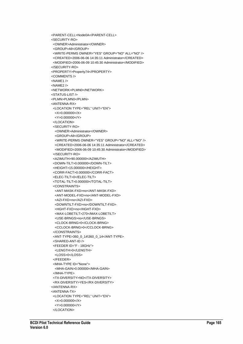
BCDI Pilot Technical Reference Guide Page 165 Version 6.0
<PARENT-CELL>Node0A</PARENT-CELL>
<SECURITY-RO>
<OWNER>Administrator</OWNER>
<GROUP>All</GROUP>
<WRITE-PERMS OWNER="YES" GROUP="NO" ALL="NO" />
<CREATED>2006-06-06 14:35:11 Administrator</CREATED>
<MODIFIED>2006-06-09 10:45:30 Administrator</MODIFIED>
</SECURITY-RO>
<PROPERTY>Property74</PROPERTY>
<COMMENTS />
<NAME1 />
<NAME2 />
<NETWORK>PLMN0</NETWORK>
<STATUS-LIST />
<PLMN>PLMN0</PLMN>
<ANTENNA-RX>
<LOCATION TYPE="REL" UNIT="EN">
<X>0.000000</X>
<Y>0.000000</Y>
</LOCATION>
<SECURITY-RO>
<OWNER>Administrator</OWNER>
<GROUP>All</GROUP>
<WRITE-PERMS OWNER="YES" GROUP="NO" ALL="NO" />
<CREATED>2006-06-06 14:35:11 Administrator</CREATED>
<MODIFIED>2006-06-09 10:45:30 Administrator</MODIFIED>
</SECURITY-RO>
<AZIMUTH>90.000000</AZIMUTH>
<DOWN-TILT>0.000000</DOWN-TILT>
<HEIGHT>15.000000</HEIGHT>
<CORR-FACT>0.000000</CORR-FACT>
<ELEC-TILT>0</ELEC-TILT>
<TOTAL-TILT>0.000000</TOTAL-TILT>
<CONSTRAINTS>
<ANT-MASK-FXD>no</ANT-MASK-FXD>
<ANT-MODEL-FXD>no</ANT-MODEL-FXD>
<AZI-FXD>no</AZI-FXD>
<DOWNTILT-FXD>no</DOWNTILT-FXD>
<HGHT-FXD>no</HGHT-FXD>
<MAX-LOBETILT>270</MAX-LOBETILT>
<USE-BRNGS>no</USE-BRNGS>
<CLOCK-BRNG>0</CLOCK-BRNG>
<CCLOCK-BRNG>0</CCLOCK-BRNG>
</CONSTRAINTS>
<ANT-TYPE>360_0_14\360_0_14</ANT-TYPE>
<SHARED-ANT-ID />
<FEEDER ID="F - 18GHz">
<LENGTH>0</LENGTH>
<LOSS>0</LOSS>
</FEEDER>
<MHA-TYPE ID="None">
<MHA-GAIN>0.000000</MHA-GAIN>
</MHA-TYPE>
<TX-DIVERSITY>NO</TX-DIVERSITY>
<RX-DIVERSITY>YES</RX-DIVERSITY>
</ANTENNA-RX>
<ANTENNA-TX>
<LOCATION TYPE="REL" UNIT="EN">
<X>0.000000</X>
<Y>0.000000</Y>
</LOCATION>
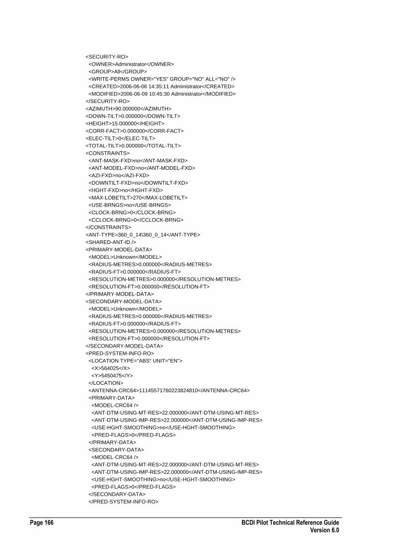
Page 166 BCDI Pilot Technical Reference Guide Version 6.0
<SECURITY-RO>
<OWNER>Administrator</OWNER>
<GROUP>All</GROUP>
<WRITE-PERMS OWNER="YES" GROUP="NO" ALL="NO" />
<CREATED>2006-06-06 14:35:11 Administrator</CREATED>
<MODIFIED>2006-06-09 10:45:30 Administrator</MODIFIED>
</SECURITY-RO>
<AZIMUTH>90.000000</AZIMUTH>
<DOWN-TILT>0.000000</DOWN-TILT>
<HEIGHT>15.000000</HEIGHT>
<CORR-FACT>0.000000</CORR-FACT>
<ELEC-TILT>0</ELEC-TILT>
<TOTAL-TILT>0.000000</TOTAL-TILT>
<CONSTRAINTS>
<ANT-MASK-FXD>no</ANT-MASK-FXD>
<ANT-MODEL-FXD>no</ANT-MODEL-FXD>
<AZI-FXD>no</AZI-FXD>
<DOWNTILT-FXD>no</DOWNTILT-FXD>
<HGHT-FXD>no</HGHT-FXD>
<MAX-LOBETILT>270</MAX-LOBETILT>
<USE-BRNGS>no</USE-BRNGS>
<CLOCK-BRNG>0</CLOCK-BRNG>
<CCLOCK-BRNG>0</CCLOCK-BRNG>
</CONSTRAINTS>
<ANT-TYPE>360_0_14\360_0_14</ANT-TYPE>
<SHARED-ANT-ID />
<PRIMARY-MODEL-DATA>
<MODEL>Unknown</MODEL>
<RADIUS-METRES>0.000000</RADIUS-METRES>
<RADIUS-FT>0.000000</RADIUS-FT>
<RESOLUTION-METRES>0.000000</RESOLUTION-METRES>
<RESOLUTION-FT>0.000000</RESOLUTION-FT>
</PRIMARY-MODEL-DATA>
<SECONDARY-MODEL-DATA>
<MODEL>Unknown</MODEL>
<RADIUS-METRES>0.000000</RADIUS-METRES>
<RADIUS-FT>0.000000</RADIUS-FT>
<RESOLUTION-METRES>0.000000</RESOLUTION-METRES>
<RESOLUTION-FT>0.000000</RESOLUTION-FT>
</SECONDARY-MODEL-DATA>
<PRED-SYSTEM-INFO-RO>
<LOCATION TYPE="ABS" UNIT="EN">
<X>564025</X>
<Y>5450475</Y>
</LOCATION>
<ANTENNA-CRC64>11145571760223824810</ANTENNA-CRC64>
<PRIMARY-DATA>
<MODEL-CRC64 />
<ANT-DTM-USING-MT-RES>22.000000</ANT-DTM-USING-MT-RES>
<ANT-DTM-USING-IMP-RES>22.000000</ANT-DTM-USING-IMP-RES>
<USE-HGHT-SMOOTHING>no</USE-HGHT-SMOOTHING>
<PRED-FLAGS>0</PRED-FLAGS>
</PRIMARY-DATA>
<SECONDARY-DATA>
<MODEL-CRC64 />
<ANT-DTM-USING-MT-RES>22.000000</ANT-DTM-USING-MT-RES>
<ANT-DTM-USING-IMP-RES>22.000000</ANT-DTM-USING-IMP-RES>
<USE-HGHT-SMOOTHING>no</USE-HGHT-SMOOTHING>
<PRED-FLAGS>0</PRED-FLAGS>
</SECONDARY-DATA>
</PRED-SYSTEM-INFO-RO>

BCDI Pilot Technical Reference Guide Page 167 Version 6.0
<FEEDER ID="F - 18GHz">
<LENGTH>0</LENGTH>
<LOSS>0</LOSS>
</FEEDER>
<MHA-TYPE ID="None">
<MHA-GAIN>0.000000</MHA-GAIN>
</MHA-TYPE>
<TX-DIVERSITY>NO</TX-DIVERSITY>
<RX-DIVERSITY>YES</RX-DIVERSITY>
</ANTENNA-TX>
<DL-GAIN>0.000000</DL-GAIN>
<UL-GAIN>0.000000</UL-GAIN>
<UL-NOISE_FACTOR>0.000000</UL-NOISE_FACTOR>
</WiMAX-REPEATER>
</WiMAX-REPEATER-LIST>
Mobile WiMAX Node XML File Format
The following table describes the XML file format for mobile WiMAX nodes:
Required Tags ID attribute
PLMN element
NETWORK element
PROPERTY element
Comments Relocation to another Property is possible.
<PLMN> must be an existing PLMN.
If the node is parented directly to the PLMN then <NETWORK> will be the name of the PLMN. If the node is parented to a Logical Network then <NETWORK> will be the name of an existing Logical Network. This network must be a child of the PLMN specified in the <PLMN> element.
<NODEBID>
9 Digits maximum each digit 0-9
In order to import the carriers on the node the carrier name must exist or have been previously imported.
In order to import the antennas correctly the antenna must exist and to connect the propagation model this must exist also..
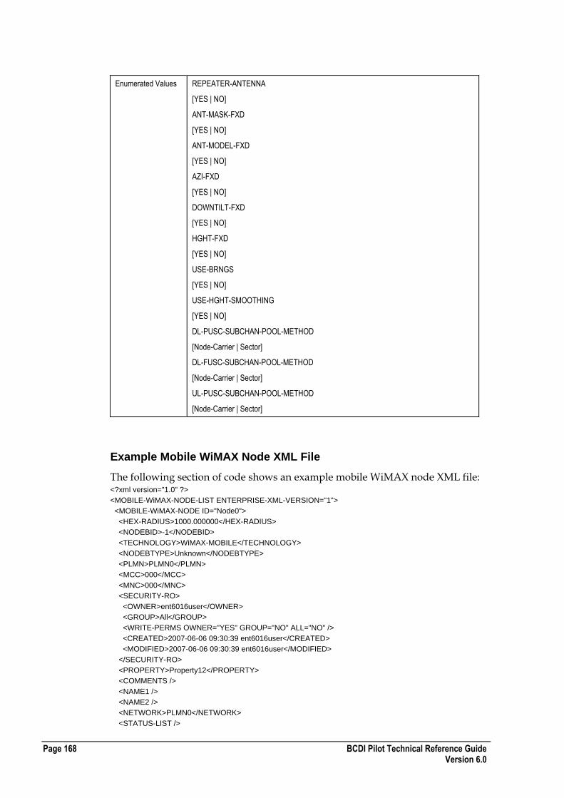
Page 168 BCDI Pilot Technical Reference Guide Version 6.0
Enumerated Values REPEATER-ANTENNA
[YES | NO]
ANT-MASK-FXD
[YES | NO]
ANT-MODEL-FXD
[YES | NO]
AZI-FXD
[YES | NO]
DOWNTILT-FXD
[YES | NO]
HGHT-FXD
[YES | NO]
USE-BRNGS
[YES | NO]
USE-HGHT-SMOOTHING
[YES | NO]
DL-PUSC-SUBCHAN-POOL-METHOD
[Node-Carrier | Sector]
DL-FUSC-SUBCHAN-POOL-METHOD
[Node-Carrier | Sector]
UL-PUSC-SUBCHAN-POOL-METHOD
[Node-Carrier | Sector]
Example Mobile WiMAX Node XML File
The following section of code shows an example mobile WiMAX node XML file: <?xml version="1.0" ?>
<MOBILE-WiMAX-NODE-LIST ENTERPRISE-XML-VERSION="1">
<MOBILE-WiMAX-NODE ID="Node0">
<HEX-RADIUS>1000.000000</HEX-RADIUS>
<NODEBID>-1</NODEBID>
<TECHNOLOGY>WiMAX-MOBILE</TECHNOLOGY>
<NODEBTYPE>Unknown</NODEBTYPE>
<PLMN>PLMN0</PLMN>
<MCC>000</MCC>
<MNC>000</MNC>
<SECURITY-RO>
<OWNER>ent6016user</OWNER>
<GROUP>All</GROUP>
<WRITE-PERMS OWNER="YES" GROUP="NO" ALL="NO" />
<CREATED>2007-06-06 09:30:39 ent6016user</CREATED>
<MODIFIED>2007-06-06 09:30:39 ent6016user</MODIFIED>
</SECURITY-RO>
<PROPERTY>Property12</PROPERTY>
<COMMENTS />
<NAME1 />
<NAME2 />
<NETWORK>PLMN0</NETWORK>
<STATUS-LIST />
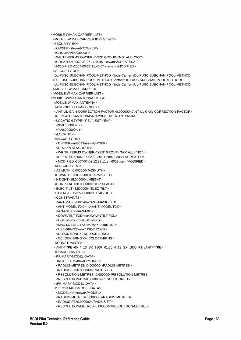
BCDI Pilot Technical Reference Guide Page 169 Version 6.0
<MOBILE-WiMAX-CARRIER-LIST>
<MOBILE-WiMAX-CARRIER ID="Carrier1">
<SECURITY-RO>
<OWNER>stewart</OWNER>
<GROUP>All</GROUP>
<WRITE-PERMS OWNER="YES" GROUP="NO" ALL="NO"/>
<CREATED>2007-03-27 11:40:07 stewart</CREATED>
<MODIFIED>2007-03-27 11:40:07 stewart</MODIFIED>
</SECURITY-RO>
<DL-PUSC-SUBCHAN-POOL-METHOD>Node-Carrier</DL-PUSC-SUBCHAN-POOL-METHOD>
<DL-FUSC-SUBCHAN-POOL-METHOD>Sector</DL-FUSC-SUBCHAN-POOL-METHOD>
<UL-PUSC-SUBCHAN-POOL-METHOD>Node-Carrier</UL-PUSC-SUBCHAN-POOL-METHOD>
</MOBILE-WiMAX-CARRIER>
</MOBILE-WiMAX-CARRIER-LIST>
<MOBILE-WiMAX-ANTENNA-LIST />
<MOBILE-WiMAX-ANTENNA>
<ANT-INDEX>1</ANT-INDEX>
<ANT-UL-GAIN-CORRECTION-FACTOR>0.000000</ANT-UL-GAIN-CORRECTION-FACTOR>
<REPEATER-ANTENNA>NO</REPEATER-ANTENNA>
<LOCATION TYPE="REL" UNIT="EN">
<X>0.000000</X>
<Y>0.000000</Y>
</LOCATION>
<SECURITY-RO>
<OWNER>ent6023user</OWNER>
<GROUP>All</GROUP>
<WRITE-PERMS OWNER="YES" GROUP="NO" ALL="NO" />
<CREATED>2007-07-02 12:39:11 ent6023user</CREATED>
<MODIFIED>2007-07-02 12:39:11 ent6023user</MODIFIED>
</SECURITY-RO>
<AZIMUTH>0.000000</AZIMUTH>
<DOWN-TILT>0.000000</DOWN-TILT>
<HEIGHT>15.000000</HEIGHT>
<CORR-FACT>0.000000</CORR-FACT>
<ELEC-TILT>3.500000</ELEC-TILT>
<TOTAL-TILT>3.500000</TOTAL-TILT>
<CONSTRAINTS>
<ANT-MASK-FXD>no</ANT-MASK-FXD>
<ANT-MODEL-FXD>no</ANT-MODEL-FXD>
<AZI-FXD>no</AZI-FXD>
<DOWNTILT-FXD>no</DOWNTILT-FXD>
<HGHT-FXD>no</HGHT-FXD>
<MAX-LOBETILT>270</MAX-LOBETILT>
<USE-BRNGS>no</USE-BRNGS>
<CLOCK-BRNG>0</CLOCK-BRNG>
<CCLOCK-BRNG>0</CCLOCK-BRNG>
</CONSTRAINTS>
<ANT-TYPE>60_4_13_SX_1800_R1\60_4_13_SX_1800_R1</ANT-TYPE>
<SHARED-ANT-ID />
<PRIMARY-MODEL-DATA>
<MODEL>Unknown</MODEL>
<RADIUS-METRES>0.000000</RADIUS-METRES>
<RADIUS-FT>0.000000</RADIUS-FT>
<RESOLUTION-METRES>0.000000</RESOLUTION-METRES>
<RESOLUTION-FT>0.000000</RESOLUTION-FT>
</PRIMARY-MODEL-DATA>
<SECONDARY-MODEL-DATA>
<MODEL>Unknown</MODEL>
<RADIUS-METRES>0.000000</RADIUS-METRES>
<RADIUS-FT>0.000000</RADIUS-FT>
<RESOLUTION-METRES>0.000000</RESOLUTION-METRES>

Page 170 BCDI Pilot Technical Reference Guide Version 6.0
<RESOLUTION-FT>0.000000</RESOLUTION-FT>
</SECONDARY-MODEL-DATA>
<PRED-SYSTEM-INFO-RO>
<LOCATION TYPE="ABS" UNIT="EN">
<X>564025</X>
<Y>5450475</Y>
</LOCATION>
<ANTENNA-CRC64>11843294365390217616</ANTENNA-CRC64>
<PRIMARY-DATA>
<MODEL-CRC64 />
<ANT-DTM-USING-MT-RES>22.000000</ANT-DTM-USING-MT-RES>
<ANT-DTM-USING-IMP-RES>22.000000</ANT-DTM-USING-IMP-RES>
<USE-HGHT-SMOOTHING>no</USE-HGHT-SMOOTHING>
<PRED-FLAGS>0</PRED-FLAGS>
</PRIMARY-DATA>
<SECONDARY-DATA>
<MODEL-CRC64 />
<ANT-DTM-USING-MT-RES>22.000000</ANT-DTM-USING-MT-RES>
<ANT-DTM-USING-IMP-RES>22.000000</ANT-DTM-USING-IMP-RES>
<USE-HGHT-SMOOTHING>no</USE-HGHT-SMOOTHING>
<PRED-FLAGS>0</PRED-FLAGS>
</SECONDARY-DATA>
</PRED-SYSTEM-INFO-RO>
</MOBILE-WiMAX-ANTENNA>
</MOBILE-WiMAX-ANTENNA-LIST>
</MOBILE-WiMAX-NODE>
</MOBILE-WiMAX-NODE-LIST>
Mobile WiMAX Cell XML File Format
The following table describes the XML file format for mobile WiMAX cells:
Required Tags ID attribute
PARENT The node this cell is connected to
Comments LOCALCELLID Maximum 9 digits each digit 0-9
LAC Maximum 5 digits each digit 0-9
RAC Maximum 3 digits each digit 0-9
SAC Maximum 3 digits each digit 0-9
LCR Unused
MOBILE-WIMAX-CELL-FEEDER
ANT-INDEX must be a valid index to the Parent Node antenna.
FEEDER-TYPE and MHA-TYPE must exist already or have been imported otherwise these equipment types will not be set.
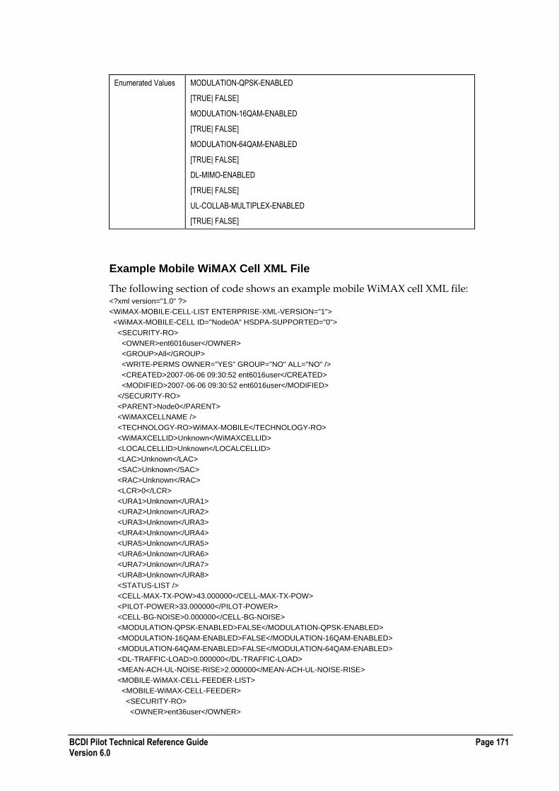
BCDI Pilot Technical Reference Guide Page 171 Version 6.0
Enumerated Values MODULATION-QPSK-ENABLED
[TRUE| FALSE]
MODULATION-16QAM-ENABLED
[TRUE| FALSE]
MODULATION-64QAM-ENABLED
[TRUE| FALSE]
DL-MIMO-ENABLED
[TRUE| FALSE]
UL-COLLAB-MULTIPLEX-ENABLED
[TRUE| FALSE]
Example Mobile WiMAX Cell XML File
The following section of code shows an example mobile WiMAX cell XML file: <?xml version="1.0" ?>
<WiMAX-MOBILE-CELL-LIST ENTERPRISE-XML-VERSION="1">
<WiMAX-MOBILE-CELL ID="Node0A" HSDPA-SUPPORTED="0">
<SECURITY-RO>
<OWNER>ent6016user</OWNER>
<GROUP>All</GROUP>
<WRITE-PERMS OWNER="YES" GROUP="NO" ALL="NO" />
<CREATED>2007-06-06 09:30:52 ent6016user</CREATED>
<MODIFIED>2007-06-06 09:30:52 ent6016user</MODIFIED>
</SECURITY-RO>
<PARENT>Node0</PARENT>
<WiMAXCELLNAME />
<TECHNOLOGY-RO>WiMAX-MOBILE</TECHNOLOGY-RO>
<WiMAXCELLID>Unknown</WiMAXCELLID>
<LOCALCELLID>Unknown</LOCALCELLID>
<LAC>Unknown</LAC>
<SAC>Unknown</SAC>
<RAC>Unknown</RAC>
<LCR>0</LCR>
<URA1>Unknown</URA1>
<URA2>Unknown</URA2>
<URA3>Unknown</URA3>
<URA4>Unknown</URA4>
<URA5>Unknown</URA5>
<URA6>Unknown</URA6>
<URA7>Unknown</URA7>
<URA8>Unknown</URA8>
<STATUS-LIST />
<CELL-MAX-TX-POW>43.000000</CELL-MAX-TX-POW>
<PILOT-POWER>33.000000</PILOT-POWER>
<CELL-BG-NOISE>0.000000</CELL-BG-NOISE>
<MODULATION-QPSK-ENABLED>FALSE</MODULATION-QPSK-ENABLED>
<MODULATION-16QAM-ENABLED>FALSE</MODULATION-16QAM-ENABLED>
<MODULATION-64QAM-ENABLED>FALSE</MODULATION-64QAM-ENABLED>
<DL-TRAFFIC-LOAD>0.000000</DL-TRAFFIC-LOAD>
<MEAN-ACH-UL-NOISE-RISE>2.000000</MEAN-ACH-UL-NOISE-RISE>
<MOBILE-WiMAX-CELL-FEEDER-LIST>
<MOBILE-WiMAX-CELL-FEEDER>
<SECURITY-RO>
<OWNER>ent36user</OWNER>
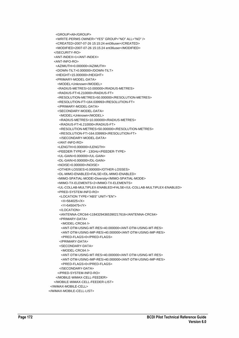
Page 172 BCDI Pilot Technical Reference Guide Version 6.0
<GROUP>All</GROUP>
<WRITE-PERMS OWNER="YES" GROUP="NO" ALL="NO" />
<CREATED>2007-07-26 15:15:24 ent36user</CREATED>
<MODIFIED>2007-07-26 15:15:24 ent36user</MODIFIED>
</SECURITY-RO>
<ANT-INDEX>1</ANT-INDEX>
<ANT-INFO-RO>
<AZIMUTH>0.000000</AZIMUTH>
<DOWN-TILT>0.000000</DOWN-TILT>
<HEIGHT>15.000000</HEIGHT>
<PRIMARY-MODEL-DATA>
<MODEL>Unknown</MODEL>
<RADIUS-METRES>10.000000</RADIUS-METRES>
<RADIUS-FT>6.210000</RADIUS-FT>
<RESOLUTION-METRES>50.000000</RESOLUTION-METRES>
<RESOLUTION-FT>164.039993</RESOLUTION-FT>
</PRIMARY-MODEL-DATA>
<SECONDARY-MODEL-DATA>
<MODEL>Unknown</MODEL>
<RADIUS-METRES>10.000000</RADIUS-METRES>
<RADIUS-FT>6.210000</RADIUS-FT>
<RESOLUTION-METRES>50.000000</RESOLUTION-METRES>
<RESOLUTION-FT>164.039993</RESOLUTION-FT>
</SECONDARY-MODEL-DATA>
</ANT-INFO-RO>
<LENGTH>0.000000</LENGTH>
<FEEDER-TYPE>F - 13GHz</FEEDER-TYPE>
<UL-GAIN>0.000000</UL-GAIN>
<DL-GAIN>0.000000</DL-GAIN>
<NOISE>0.000000</NOISE>
<OTHER-LOSSES>0.000000</OTHER-LOSSES>
<DL-MIMO-ENABLED>FALSE</DL-MIMO-ENABLED>
<MIMO-SPATIAL-MODE>Diversity</MIMO-SPATIAL-MODE>
<MIMO-TX-ELEMENTS>2</MIMO-TX-ELEMENTS>
<UL-COLLAB-MULTIPLEX-ENABLED>FALSE</UL-COLLAB-MULTIPLEX-ENABLED>
<PRED-SYSTEM-INFO-RO>
<LOCATION TYPE="ABS" UNIT="EN">
<X>564025</X>
<Y>5450475</Y>
</LOCATION>
<ANTENNA-CRC64>11843294365390217616</ANTENNA-CRC64>
<PRIMARY-DATA>
<MODEL-CRC64 />
<ANT-DTM-USING-MT-RES>40.000000</ANT-DTM-USING-MT-RES>
<ANT-DTM-USING-IMP-RES>40.000000</ANT-DTM-USING-IMP-RES>
<PRED-FLAGS>0</PRED-FLAGS>
</PRIMARY-DATA>
<SECONDARY-DATA>
<MODEL-CRC64 />
<ANT-DTM-USING-MT-RES>40.000000</ANT-DTM-USING-MT-RES>
<ANT-DTM-USING-IMP-RES>40.000000</ANT-DTM-USING-IMP-RES>
<PRED-FLAGS>0</PRED-FLAGS>
</SECONDARY-DATA>
</PRED-SYSTEM-INFO-RO>
</MOBILE-WiMAX-CELL-FEEDER>
</MOBILE-WiMAX-CELL-FEEDER-LIST>
</WiMAX-MOBILE-CELL>
</WiMAX-MOBILE-CELL-LIST>
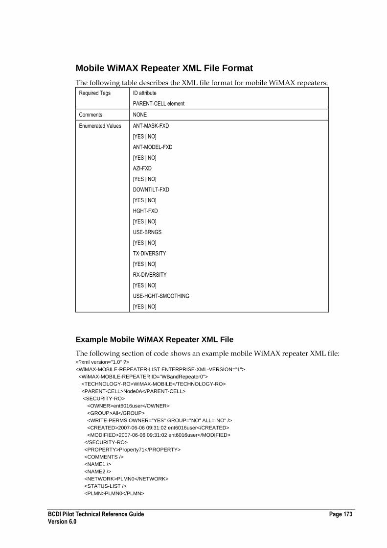
BCDI Pilot Technical Reference Guide Page 173 Version 6.0
Mobile WiMAX Repeater XML File Format
The following table describes the XML file format for mobile WiMAX repeaters:
Required Tags ID attribute
PARENT-CELL element
Comments NONE
Enumerated Values ANT-MASK-FXD
[YES | NO]
ANT-MODEL-FXD
[YES | NO]
AZI-FXD
[YES | NO]
DOWNTILT-FXD
[YES | NO]
HGHT-FXD
[YES | NO]
USE-BRNGS
[YES | NO]
TX-DIVERSITY
[YES | NO]
RX-DIVERSITY
[YES | NO]
USE-HGHT-SMOOTHING
[YES | NO]
Example Mobile WiMAX Repeater XML File
The following section of code shows an example mobile WiMAX repeater XML file: <?xml version="1.0" ?>
<WiMAX-MOBILE-REPEATER-LIST ENTERPRISE-XML-VERSION="1">
<WiMAX-MOBILE-REPEATER ID="WBandRepeater0">
<TECHNOLOGY-RO>WiMAX-MOBILE</TECHNOLOGY-RO>
<PARENT-CELL>Node0A</PARENT-CELL>
<SECURITY-RO>
<OWNER>ent6016user</OWNER>
<GROUP>All</GROUP>
<WRITE-PERMS OWNER="YES" GROUP="NO" ALL="NO" />
<CREATED>2007-06-06 09:31:02 ent6016user</CREATED>
<MODIFIED>2007-06-06 09:31:02 ent6016user</MODIFIED>
</SECURITY-RO>
<PROPERTY>Property71</PROPERTY>
<COMMENTS />
<NAME1 />
<NAME2 />
<NETWORK>PLMN0</NETWORK>
<STATUS-LIST />
<PLMN>PLMN0</PLMN>

Page 174 BCDI Pilot Technical Reference Guide Version 6.0
<ANTENNA-RX>
<LOCATION TYPE="REL" UNIT="EN">
<X>0.000000</X>
<Y>0.000000</Y>
</LOCATION>
<SECURITY-RO>
<OWNER>ent6016user</OWNER>
<GROUP>All</GROUP>
<WRITE-PERMS OWNER="YES" GROUP="NO" ALL="NO" />
<CREATED>2007-06-06 09:31:02 ent6016user</CREATED>
<MODIFIED>2007-06-06 09:31:02 ent6016user</MODIFIED>
</SECURITY-RO>
<AZIMUTH>0.000000</AZIMUTH>
<DOWN-TILT>0.000000</DOWN-TILT>
<HEIGHT>15.000000</HEIGHT>
<CORR-FACT>0.000000</CORR-FACT>
<PRED-RADIUS>10.000000</PRED-RADIUS>
<ELEC-TILT>0.000000</ELEC-TILT>
<TOTAL-TILT>0.000000</TOTAL-TILT>
<CONSTRAINTS>
<ANT-MASK-FXD>no</ANT-MASK-FXD>
<ANT-MODEL-FXD>no</ANT-MODEL-FXD>
<AZI-FXD>no</AZI-FXD>
<DOWNTILT-FXD>no</DOWNTILT-FXD>
<HGHT-FXD>no</HGHT-FXD>
<MAX-LOBETILT>270</MAX-LOBETILT>
<USE-BRNGS>no</USE-BRNGS>
<CLOCK-BRNG>0</CLOCK-BRNG>
<CCLOCK-BRNG>0</CCLOCK-BRNG>
</CONSTRAINTS>
<ANT-TYPE>Unknown</ANT-TYPE>
<SHARED-ANT-ID />
<FEEDER ID="Unknown">
<LENGTH>0</LENGTH>
<LOSS>0</LOSS>
</FEEDER>
<MHA-TYPE ID="None">
<MHA-GAIN>0.000000</MHA-GAIN>
</MHA-TYPE>
<TX-DIVERSITY>NO</TX-DIVERSITY>
<RX-DIVERSITY>NO</RX-DIVERSITY>
<PRED-MODEL>Unknown</PRED-MODEL>
</ANTENNA-RX>
<ANTENNA-TX>
<LOCATION TYPE="REL" UNIT="EN">
<X>0.000000</X>
<Y>0.000000</Y>
</LOCATION>
<SECURITY-RO>
<OWNER>ent6016user</OWNER>
<GROUP>All</GROUP>
<WRITE-PERMS OWNER="YES" GROUP="NO" ALL="NO" />
<CREATED>2007-06-06 09:31:02 ent6016user</CREATED>
<MODIFIED>2007-06-06 09:31:02 ent6016user</MODIFIED>
</SECURITY-RO>
<AZIMUTH>0.000000</AZIMUTH>
<DOWN-TILT>0.000000</DOWN-TILT>
<HEIGHT>15.000000</HEIGHT>
<CORR-FACT>0.000000</CORR-FACT>
<ELEC-TILT>0.000000</ELEC-TILT>
<TOTAL-TILT>0.000000</TOTAL-TILT>
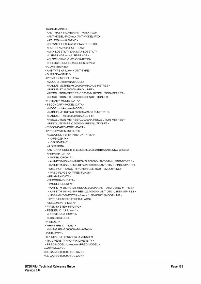
BCDI Pilot Technical Reference Guide Page 175 Version 6.0
<CONSTRAINTS>
<ANT-MASK-FXD>no</ANT-MASK-FXD>
<ANT-MODEL-FXD>no</ANT-MODEL-FXD>
<AZI-FXD>no</AZI-FXD>
<DOWNTILT-FXD>no</DOWNTILT-FXD>
<HGHT-FXD>no</HGHT-FXD>
<MAX-LOBETILT>270</MAX-LOBETILT>
<USE-BRNGS>no</USE-BRNGS>
<CLOCK-BRNG>0</CLOCK-BRNG>
<CCLOCK-BRNG>0</CCLOCK-BRNG>
</CONSTRAINTS>
<ANT-TYPE>Unknown</ANT-TYPE>
<SHARED-ANT-ID />
<PRIMARY-MODEL-DATA>
<MODEL>Unknown</MODEL>
<RADIUS-METRES>0.000000</RADIUS-METRES>
<RADIUS-FT>0.000000</RADIUS-FT>
<RESOLUTION-METRES>0.000000</RESOLUTION-METRES>
<RESOLUTION-FT>0.000000</RESOLUTION-FT>
</PRIMARY-MODEL-DATA>
<SECONDARY-MODEL-DATA>
<MODEL>Unknown</MODEL>
<RADIUS-METRES>0.000000</RADIUS-METRES>
<RADIUS-FT>0.000000</RADIUS-FT>
<RESOLUTION-METRES>0.000000</RESOLUTION-METRES>
<RESOLUTION-FT>0.000000</RESOLUTION-FT>
</SECONDARY-MODEL-DATA>
<PRED-SYSTEM-INFO-RO>
<LOCATION TYPE="ABS" UNIT="EN">
<X>564025</X>
<Y>5450475</Y>
</LOCATION>
<ANTENNA-CRC64>11145571760223824810</ANTENNA-CRC64>
<PRIMARY-DATA>
<MODEL-CRC64 />
<ANT-DTM-USING-MT-RES>22.000000</ANT-DTM-USING-MT-RES>
<ANT-DTM-USING-IMP-RES>22.000000</ANT-DTM-USING-IMP-RES>
<USE-HGHT-SMOOTHING>no</USE-HGHT-SMOOTHING>
<PRED-FLAGS>0</PRED-FLAGS>
</PRIMARY-DATA>
<SECONDARY-DATA>
<MODEL-CRC64 />
<ANT-DTM-USING-MT-RES>22.000000</ANT-DTM-USING-MT-RES>
<ANT-DTM-USING-IMP-RES>22.000000</ANT-DTM-USING-IMP-RES>
<USE-HGHT-SMOOTHING>no</USE-HGHT-SMOOTHING>
<PRED-FLAGS>0</PRED-FLAGS>
</SECONDARY-DATA>
</PRED-SYSTEM-INFO-RO>
<FEEDER ID="Unknown">
<LENGTH>0</LENGTH>
<LOSS>0</LOSS>
</FEEDER>
<MHA-TYPE ID="None">
<MHA-GAIN>0.000000</MHA-GAIN>
</MHA-TYPE>
<TX-DIVERSITY>NO</TX-DIVERSITY>
<RX-DIVERSITY>NO</RX-DIVERSITY>
<PRED-MODEL>Unknown</PRED-MODEL>
</ANTENNA-TX>
<DL-GAIN>0.000000</DL-GAIN>
<UL-GAIN>0.000000</UL-GAIN>

Page 176 BCDI Pilot Technical Reference Guide Version 6.0
<UL-NOISE_FACTOR>0.000000</UL-NOISE_FACTOR>
</WiMAX-MOBILE-REPEATER>
</WiMAX-MOBILE-REPEATER-LIST>
Node Sim Traffic XML File Format
The following table describes the XML file format for Node Sim Traffic:
Required Tags NODEB ID attribute
SERVICE ID attribute
SERVICE TYPE attribute
UL-BEARER ID attribute
DL-BEARER ID attribute
Comments 0 or more <PRIMARY-TRAFFIC> elements can exist.
0 or more <HO-NODE> elements can exist.
<CELL-COUNT>, and <ACTIVITY> attributes are read-only values.
A service matching the <ID> and <TYPE> attributes must exist already or have been imported otherwise this traffic node will fail to import.
The bearer <ID> attributes must exist already or have been imported otherwise this traffic node will fail to import.
If a traffic node fails to be imported, a message giving the cause of this failure can be found in the message log.
Enumerated Values
TYPE
[Voice|RTD|PS]
Example Node Sim Traffic XML File
The following section of code shows an example Node Sim Traffic XML file: <?xml version="1.0"?>
<NODEB-TRAFFIC-LIST ENTERPRISE-XML-VERSION="1">
<NODEB ID="NodeB2" CELL-COUNT="0">
<SECURITY-RO>
<OWNER>b</OWNER>
<GROUP>All</GROUP>
<WRITE-PERMS OWNER="YES" GROUP="YES" ALL="YES"/>
<CREATED>2004-05-12 12:12:31 b</CREATED>
<MODIFIED>2004-05-12 12:12:53 b</MODIFIED>
</SECURITY-RO>
<PRIMARY-TRAFFIC>
<SECURITY-RO>
<OWNER>b</OWNER>
<GROUP>All</GROUP>
<WRITE-PERMS OWNER="YES" GROUP="YES" ALL="YES"/>
<CREATED>2004-05-12 12:12:53 b</CREATED>
<MODIFIED>2004-05-12 12:12:53 b</MODIFIED>
</SECURITY-RO>
<SERVICE ID="UMTS Voice Pedestrian" TYPE="Voice"/>
<UL-BEARER ID="UMTS Voice UL" ACTIVITY="50.0"/>
<DL-BEARER ID="UMTS Voice DL" ACTIVITY="50.0"/>
<SUBSCRIBER MAX="28.0" MEAN="14.7" STD-DEV="3.7"/>
</PRIMARY-TRAFFIC>
<HO-TRAFFIC-LIST>
<HO-NODE ID="NodeB1">
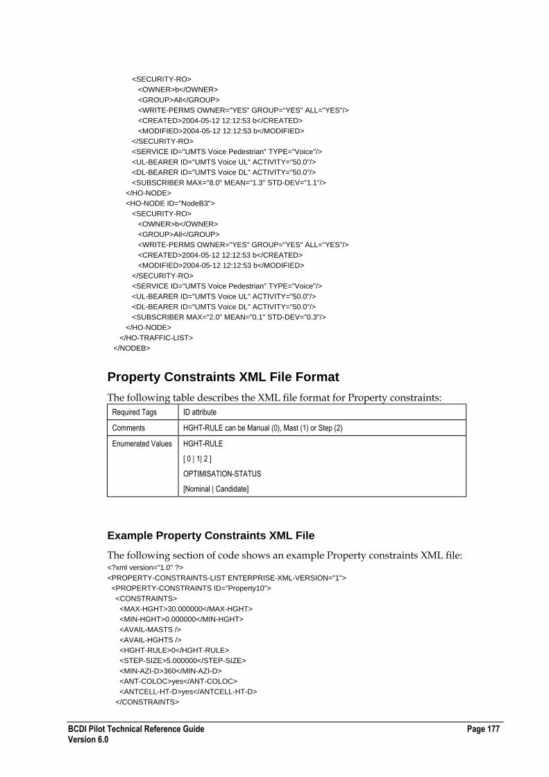
BCDI Pilot Technical Reference Guide Page 177 Version 6.0
<SECURITY-RO>
<OWNER>b</OWNER>
<GROUP>All</GROUP>
<WRITE-PERMS OWNER="YES" GROUP="YES" ALL="YES"/>
<CREATED>2004-05-12 12:12:53 b</CREATED>
<MODIFIED>2004-05-12 12:12:53 b</MODIFIED>
</SECURITY-RO>
<SERVICE ID="UMTS Voice Pedestrian" TYPE="Voice"/>
<UL-BEARER ID="UMTS Voice UL" ACTIVITY="50.0"/>
<DL-BEARER ID="UMTS Voice DL" ACTIVITY="50.0"/>
<SUBSCRIBER MAX="8.0" MEAN="1.3" STD-DEV="1.1"/>
</HO-NODE>
<HO-NODE ID="NodeB3">
<SECURITY-RO>
<OWNER>b</OWNER>
<GROUP>All</GROUP>
<WRITE-PERMS OWNER="YES" GROUP="YES" ALL="YES"/>
<CREATED>2004-05-12 12:12:53 b</CREATED>
<MODIFIED>2004-05-12 12:12:53 b</MODIFIED>
</SECURITY-RO>
<SERVICE ID="UMTS Voice Pedestrian" TYPE="Voice"/>
<UL-BEARER ID="UMTS Voice UL" ACTIVITY="50.0"/>
<DL-BEARER ID="UMTS Voice DL" ACTIVITY="50.0"/>
<SUBSCRIBER MAX="2.0" MEAN="0.1" STD-DEV="0.3"/>
</HO-NODE>
</HO-TRAFFIC-LIST>
</NODEB>
Property Constraints XML File Format
The following table describes the XML file format for Property constraints:
Required Tags ID attribute
Comments HGHT-RULE can be Manual (0), Mast (1) or Step (2)
Enumerated Values HGHT-RULE
[ 0 | 1| 2 ]
OPTIMISATION-STATUS
[Nominal | Candidate]
Example Property Constraints XML File
The following section of code shows an example Property constraints XML file: <?xml version="1.0" ?>
<PROPERTY-CONSTRAINTS-LIST ENTERPRISE-XML-VERSION="1">
<PROPERTY-CONSTRAINTS ID="Property10">
<CONSTRAINTS>
<MAX-HGHT>30.000000</MAX-HGHT>
<MIN-HGHT>0.000000</MIN-HGHT>
<AVAIL-MASTS />
<AVAIL-HGHTS />
<HGHT-RULE>0</HGHT-RULE>
<STEP-SIZE>5.000000</STEP-SIZE>
<MIN-AZI-D>360</MIN-AZI-D>
<ANT-COLOC>yes</ANT-COLOC>
<ANTCELL-HT-D>yes</ANTCELL-HT-D>
</CONSTRAINTS>

Page 178 BCDI Pilot Technical Reference Guide Version 6.0
<GRID-CONSTRAINTS>
<OPTIMISATION-STATUS>Nominal</OPTIMISATION-STATUS>
<LOCATION-FIXED>NO</LOCATION-FIXED>
<ALWAYS-CONSIDER>NO</ALWAYS-CONSIDER>
<GRID-CANDIDATE-LIST />
</GRID-CONSTRAINTS>
</PROPERTY-CONSTRAINTS>
<PROPERTY-CONSTRAINTS ID="PROPERTY2">
<CONSTRAINTS>
<MAX-HGHT>30.000000</MAX-HGHT>
<MIN-HGHT>0.000000</MIN-HGHT>
<AVAIL-MASTS />
<AVAIL-HGHTS />
<HGHT-RULE>1</HGHT-RULE>
<STEP-SIZE>1.000000</STEP-SIZE>
<MIN-AZI-D>15</MIN-AZI-D>
<ANT-COLOC>no</ANT-COLOC>
<ANTCELL-HT-D>no</ANTCELL-HT-D>
</CONSTRAINTS>
<GRID-CONSTRAINTS>
<OPTIMISATION-STATUS>Nominal</OPTIMISATION-STATUS>
<LOCATION-FIXED>NO</LOCATION-FIXED>
<ALWAYS-CONSIDER>NO</ALWAYS-CONSIDER>
<GRID-CANDIDATE-LIST />
</GRID-CONSTRAINTS>
</PROPERTY-CONSTRAINTS>
<PROPERTY-CONSTRAINTS ID="Property59">
<CONSTRAINTS>
<MAX-HGHT>30.000000</MAX-HGHT>
<MIN-HGHT>0.000000</MIN-HGHT>
<AVAIL-MASTS />
<AVAIL-HGHTS />
<HGHT-RULE>0</HGHT-RULE>
<STEP-SIZE>5.000000</STEP-SIZE>
<MIN-AZI-D>360</MIN-AZI-D>
<ANT-COLOC>yes</ANT-COLOC>
<ANTCELL-HT-D>yes</ANTCELL-HT-D>
</CONSTRAINTS>
<GRID-CONSTRAINTS>
<OPTIMISATION-STATUS>Nominal</OPTIMISATION-STATUS>
<LOCATION-FIXED>NO</LOCATION-FIXED>
<ALWAYS-CONSIDER>NO</ALWAYS-CONSIDER>
<GRID-CANDIDATE-LIST />
</GRID-CONSTRAINTS>
</PROPERTY-CONSTRAINTS>
</PROPERTY-CONSTRAINTS-LIST>
Cell Site/Node Constraints XML File Format
The following table describes the XML file format for cell site/node constraints:
Required Tags ID attribute
Comments None
Enumerated Values None

BCDI Pilot Technical Reference Guide Page 179 Version 6.0
Example Cell Site/Node Constraints XML File
The following section of code shows an example cell site/node constraints XML file: <?xml version="1.0"?>
<SITE-CONSTRAINTS-LIST ENTERPRISE-XML-VERSION="1">
<SITE-CONSTRAINTS ID="SITE0" TECH="GSM">
<GRID-CONSTRAINTS>
<MIN-SECTOR>0</MIN-SECTOR>
<MAX-SECTOR>0</MAX-SECTOR>
<FIX-CONFIGURATION>NO</FIX-CONFIGURATION>
<NODEB-TYPE-FIXED>NO</NODEB-TYPE-FIXED>
<GRID-CONFIGURATION-LIST />
</GRID-CONSTRAINTS>
</SITE-CONSTRAINTS>
<SITE-CONSTRAINTS ID="SITE1" TECH="GSM">
<GRID-CONSTRAINTS>
<MIN-SECTOR>0</MIN-SECTOR>
<MAX-SECTOR>0</MAX-SECTOR>
<FIX-CONFIGURATION>NO</FIX-CONFIGURATION>
<NODEB-TYPE-FIXED>NO</NODEB-TYPE-FIXED>
<GRID-CONFIGURATION-LIST />
</GRID-CONSTRAINTS>
</SITE-CONSTRAINTS>
<SITE-CONSTRAINTS ID="SITE2" TECH="GSM">
<GRID-CONSTRAINTS>
<MIN-SECTOR>0</MIN-SECTOR>
<MAX-SECTOR>0</MAX-SECTOR>
<FIX-CONFIGURATION>NO</FIX-CONFIGURATION>
<NODEB-TYPE-FIXED>NO</NODEB-TYPE-FIXED>
<GRID-CONFIGURATION-LIST />
</GRID-CONSTRAINTS>
</SITE-CONSTRAINTS>
<SITE-CONSTRAINTS ID="SITE3" TECH="GSM">
<GRID-CONSTRAINTS>
<MIN-SECTOR>0</MIN-SECTOR>
<MAX-SECTOR>0</MAX-SECTOR>
<FIX-CONFIGURATION>NO</FIX-CONFIGURATION>
<NODEB-TYPE-FIXED>NO</NODEB-TYPE-FIXED>
<GRID-CONFIGURATION-LIST />
</GRID-CONSTRAINTS>
</SITE-CONSTRAINTS>
<SITE-CONSTRAINTS ID="SITE4" TECH="GSM">
<GRID-CONSTRAINTS>
<MIN-SECTOR>0</MIN-SECTOR>
<MAX-SECTOR>0</MAX-SECTOR>
<FIX-CONFIGURATION>NO</FIX-CONFIGURATION>
<NODEB-TYPE-FIXED>NO</NODEB-TYPE-FIXED>
<GRID-CONFIGURATION-LIST />
</GRID-CONSTRAINTS>
</SITE-CONSTRAINTS>
<SITE-CONSTRAINTS ID="SITE7" TECH="GSM">
<GRID-CONSTRAINTS>
<MIN-SECTOR>0</MIN-SECTOR>
<MAX-SECTOR>0</MAX-SECTOR>
<FIX-CONFIGURATION>NO</FIX-CONFIGURATION>
<NODEB-TYPE-FIXED>NO</NODEB-TYPE-FIXED>
<GRID-CONFIGURATION-LIST />
</GRID-CONSTRAINTS>
</SITE-CONSTRAINTS>
</SITE-CONSTRAINTS-LIST>
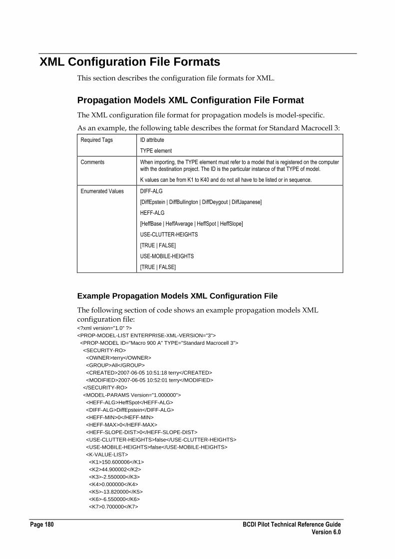
Page 180 BCDI Pilot Technical Reference Guide Version 6.0
XML Configuration File Formats
This section describes the configuration file formats for XML.
Propagation Models XML Configuration File Format
The XML configuration file format for propagation models is model-specific.
As an example, the following table describes the format for Standard Macrocell 3:
Required Tags ID attribute
TYPE element
Comments When importing, the TYPE element must refer to a model that is registered on the computer with the destination project. The ID is the particular instance of that TYPE of model.
K values can be from K1 to K40 and do not all have to be listed or in sequence.
Enumerated Values DIFF-ALG
[DiffEpstein | DiffBullington | DiffDeygout | DiffJapanese]
HEFF-ALG
[HeffBase | HeffAverage | HeffSpot | HeffSlope]
USE-CLUTTER-HEIGHTS
[TRUE | FALSE]
USE-MOBILE-HEIGHTS
[TRUE | FALSE]
Example Propagation Models XML Configuration File
The following section of code shows an example propagation models XML configuration file: <?xml version="1.0" ?>
<PROP-MODEL-LIST ENTERPRISE-XML-VERSION="3">
<PROP-MODEL ID="Macro 900 A" TYPE="Standard Macrocell 3">
<SECURITY-RO>
<OWNER>terry</OWNER>
<GROUP>All</GROUP>
<CREATED>2007-06-05 10:51:18 terry</CREATED>
<MODIFIED>2007-06-05 10:52:01 terry</MODIFIED>
</SECURITY-RO>
<MODEL-PARAMS Version="1.000000">
<HEFF-ALG>HeffSpot</HEFF-ALG>
<DIFF-ALG>DiffEpstein</DIFF-ALG>
<HEFF-MIN>0</HEFF-MIN>
<HEFF-MAX>0</HEFF-MAX>
<HEFF-SLOPE-DIST>0</HEFF-SLOPE-DIST>
<USE-CLUTTER-HEIGHTS>false</USE-CLUTTER-HEIGHTS>
<USE-MOBILE-HEIGHTS>false</USE-MOBILE-HEIGHTS>
<K-VALUE-LIST>
<K1>150.600006</K1>
<K2>44.900002</K2>
<K3>-2.550000</K3>
<K4>0.000000</K4>
<K5>-13.820000</K5>
<K6>-6.550000</K6>
<K7>0.700000</K7>

BCDI Pilot Technical Reference Guide Page 181 Version 6.0
<K8>0.000000</K8>
<K9>0.000000</K9>
<K10>0.000000</K10>
<K11>0.000000</K11>
<K12>0.000000</K12>
<K13>0.000000</K13>
<K14>0.000000</K14>
<K15>0.000000</K15>
<K16>0.000000</K16>
<K17>0.000000</K17>
<K18>0.000000</K18>
<K19>0.000000</K19>
<K20>0.000000</K20>
<K21>0.000000</K21>
<K22>0.000000</K22>
<K23>0.000000</K23>
<K24>0.000000</K24>
<K25>0.000000</K25>
<K26>0.000000</K26>
<K27>0.000000</K27>
<K28>0.000000</K28>
<K29>0.000000</K29>
<K30>0.000000</K30>
<K31>0.000000</K31>
<K32>0.000000</K32>
<K33>0.000000</K33>
<K34>0.000000</K34>
<K35>0.000000</K35>
<K36>0.000000</K36>
<K37>0.000000</K37>
<K38>0.000000</K38>
<K39>0.000000</K39>
<K40>0.000000</K40>
</K-VALUE-LIST>
<FREQUENCY>900.000000</FREQUENCY>
<EARTH-RADIUS>8491.209961</EARTH-RADIUS>
<MOBILE-HEIGHT>1.500000</MOBILE-HEIGHT>
<STD-DEV>7.500000</STD-DEV>
<CLUTTER-LIST>
<CLUTTER ID="unclassified">
<OFFSET>0.000000</OFFSET>
<CLUTTER-HEIGHT>0.000000</CLUTTER-HEIGHT>
<SEPARATION>0.000000</SEPARATION>
<MOBILE-HEIGHT>0.000000</MOBILE-HEIGHT>
</CLUTTER>
<CLUTTER ID="urban">
<OFFSET>0.000000</OFFSET>
<CLUTTER-HEIGHT>0.000000</CLUTTER-HEIGHT>
<SEPARATION>0.000000</SEPARATION>
<MOBILE-HEIGHT>0.000000</MOBILE-HEIGHT>
</CLUTTER>
<CLUTTER ID="suburban_residential">
<OFFSET>0.000000</OFFSET>
<CLUTTER-HEIGHT>0.000000</CLUTTER-HEIGHT>
<SEPARATION>0.000000</SEPARATION>
<MOBILE-HEIGHT>0.000000</MOBILE-HEIGHT>
</CLUTTER>
<CLUTTER ID="village">
<OFFSET>0.000000</OFFSET>
<CLUTTER-HEIGHT>0.000000</CLUTTER-HEIGHT>
<SEPARATION>0.000000</SEPARATION>
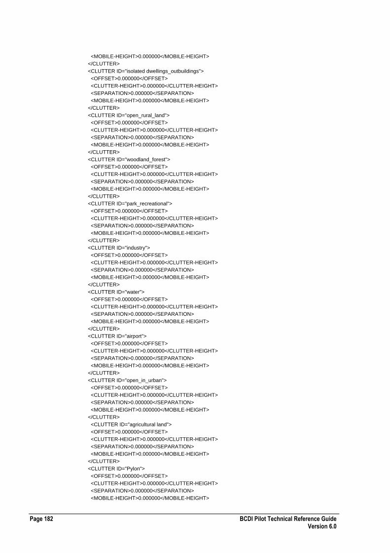
Page 182 BCDI Pilot Technical Reference Guide Version 6.0
<MOBILE-HEIGHT>0.000000</MOBILE-HEIGHT>
</CLUTTER>
<CLUTTER ID="isolated dwellings_outbuildings">
<OFFSET>0.000000</OFFSET>
<CLUTTER-HEIGHT>0.000000</CLUTTER-HEIGHT>
<SEPARATION>0.000000</SEPARATION>
<MOBILE-HEIGHT>0.000000</MOBILE-HEIGHT>
</CLUTTER>
<CLUTTER ID="open_rural_land">
<OFFSET>0.000000</OFFSET>
<CLUTTER-HEIGHT>0.000000</CLUTTER-HEIGHT>
<SEPARATION>0.000000</SEPARATION>
<MOBILE-HEIGHT>0.000000</MOBILE-HEIGHT>
</CLUTTER>
<CLUTTER ID="woodland_forest">
<OFFSET>0.000000</OFFSET>
<CLUTTER-HEIGHT>0.000000</CLUTTER-HEIGHT>
<SEPARATION>0.000000</SEPARATION>
<MOBILE-HEIGHT>0.000000</MOBILE-HEIGHT>
</CLUTTER>
<CLUTTER ID="park_recreational">
<OFFSET>0.000000</OFFSET>
<CLUTTER-HEIGHT>0.000000</CLUTTER-HEIGHT>
<SEPARATION>0.000000</SEPARATION>
<MOBILE-HEIGHT>0.000000</MOBILE-HEIGHT>
</CLUTTER>
<CLUTTER ID="industry">
<OFFSET>0.000000</OFFSET>
<CLUTTER-HEIGHT>0.000000</CLUTTER-HEIGHT>
<SEPARATION>0.000000</SEPARATION>
<MOBILE-HEIGHT>0.000000</MOBILE-HEIGHT>
</CLUTTER>
<CLUTTER ID="water">
<OFFSET>0.000000</OFFSET>
<CLUTTER-HEIGHT>0.000000</CLUTTER-HEIGHT>
<SEPARATION>0.000000</SEPARATION>
<MOBILE-HEIGHT>0.000000</MOBILE-HEIGHT>
</CLUTTER>
<CLUTTER ID="airport">
<OFFSET>0.000000</OFFSET>
<CLUTTER-HEIGHT>0.000000</CLUTTER-HEIGHT>
<SEPARATION>0.000000</SEPARATION>
<MOBILE-HEIGHT>0.000000</MOBILE-HEIGHT>
</CLUTTER>
<CLUTTER ID="open_in_urban">
<OFFSET>0.000000</OFFSET>
<CLUTTER-HEIGHT>0.000000</CLUTTER-HEIGHT>
<SEPARATION>0.000000</SEPARATION>
<MOBILE-HEIGHT>0.000000</MOBILE-HEIGHT>
</CLUTTER>
<CLUTTER ID="agricultural land">
<OFFSET>0.000000</OFFSET>
<CLUTTER-HEIGHT>0.000000</CLUTTER-HEIGHT>
<SEPARATION>0.000000</SEPARATION>
<MOBILE-HEIGHT>0.000000</MOBILE-HEIGHT>
</CLUTTER>
<CLUTTER ID="Pylon">
<OFFSET>0.000000</OFFSET>
<CLUTTER-HEIGHT>0.000000</CLUTTER-HEIGHT>
<SEPARATION>0.000000</SEPARATION>
<MOBILE-HEIGHT>0.000000</MOBILE-HEIGHT>

BCDI Pilot Technical Reference Guide Page 183 Version 6.0
</CLUTTER>
<CLUTTER ID="sea">
<OFFSET>0.000000</OFFSET>
<CLUTTER-HEIGHT>0.000000</CLUTTER-HEIGHT>
<SEPARATION>0.000000</SEPARATION>
<MOBILE-HEIGHT>0.000000</MOBILE-HEIGHT>
</CLUTTER>
<CLUTTER ID="test5">
<OFFSET>0.000000</OFFSET>
<CLUTTER-HEIGHT>0.000000</CLUTTER-HEIGHT>
<SEPARATION>0.000000</SEPARATION>
<MOBILE-HEIGHT>0.000000</MOBILE-HEIGHT>
</CLUTTER>
</CLUTTER-LIST>
<USER-TEXT />
</MODEL-PARAMS>
<COMMENTS />
</PROP-MODEL>
GSM/AMPS Carriers XML Configuration File Format
The following table describes the XML configuration file format for GSM/AMPS carriers:
Required Tags n/a
Comments Each CARRIER element can contain as many carriers as required.
Enumerated Values None
Example GSM/AMPS Carriers XML Configuration File
The following section of code shows an example GSM/AMPS carriers XML configuration file: <CARRIERS-LIST ENTERPRISE-XML-VERSION="1">
<CARRIERS>
<CARRIER>1,2,3,4,5,6,7,8,9,10,11,12,13,14,15,16,17,18,19,20</CARRIER>
<CARRIER>21,22,23,24,25,26,27,28,29,30,31,32,33,34,35,36,37,38,39,40</CARRIER>
<CARRIER>41,42,43,44,45,46,47,48,512,513,514,515,516,517,518,519,520,521,522,523</CARRIER>
<CARRIER>524,525,526,527,528,529,530,531,532,533,534,535,536</CARRIER>
</CARRIERS>
</CARRIERS-LIST>
GSM/AMPS Carrier Layer XML Configuration File Format
The following table describes the XML configuration file format for GSM/AMPS carrier layers:
Required Tags ID attribute
Comments AMPS-CC applies to AMP network only.
Enumerated Values AMPS-CC
[sat | dvcct | dcc]
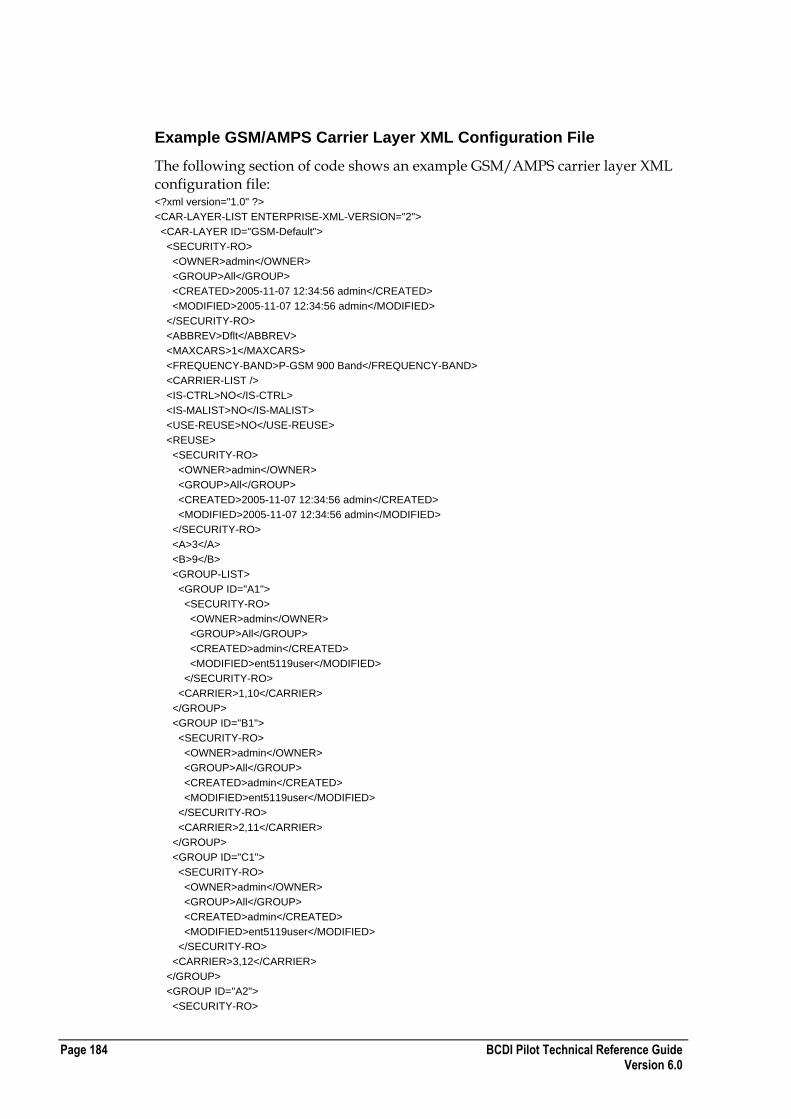
Page 184 BCDI Pilot Technical Reference Guide Version 6.0
Example GSM/AMPS Carrier Layer XML Configuration File
The following section of code shows an example GSM/AMPS carrier layer XML configuration file: <?xml version="1.0" ?>
<CAR-LAYER-LIST ENTERPRISE-XML-VERSION="2">
<CAR-LAYER ID="GSM-Default">
<SECURITY-RO>
<OWNER>admin</OWNER>
<GROUP>All</GROUP>
<CREATED>2005-11-07 12:34:56 admin</CREATED>
<MODIFIED>2005-11-07 12:34:56 admin</MODIFIED>
</SECURITY-RO>
<ABBREV>Dflt</ABBREV>
<MAXCARS>1</MAXCARS>
<FREQUENCY-BAND>P-GSM 900 Band</FREQUENCY-BAND>
<CARRIER-LIST />
<IS-CTRL>NO</IS-CTRL>
<IS-MALIST>NO</IS-MALIST>
<USE-REUSE>NO</USE-REUSE>
<REUSE>
<SECURITY-RO>
<OWNER>admin</OWNER>
<GROUP>All</GROUP>
<CREATED>2005-11-07 12:34:56 admin</CREATED>
<MODIFIED>2005-11-07 12:34:56 admin</MODIFIED>
</SECURITY-RO>
<A>3</A>
<B>9</B>
<GROUP-LIST>
<GROUP ID="A1">
<SECURITY-RO>
<OWNER>admin</OWNER>
<GROUP>All</GROUP>
<CREATED>admin</CREATED>
<MODIFIED>ent5119user</MODIFIED>
</SECURITY-RO>
<CARRIER>1,10</CARRIER>
</GROUP>
<GROUP ID="B1">
<SECURITY-RO>
<OWNER>admin</OWNER>
<GROUP>All</GROUP>
<CREATED>admin</CREATED>
<MODIFIED>ent5119user</MODIFIED>
</SECURITY-RO>
<CARRIER>2,11</CARRIER>
</GROUP>
<GROUP ID="C1">
<SECURITY-RO>
<OWNER>admin</OWNER>
<GROUP>All</GROUP>
<CREATED>admin</CREATED>
<MODIFIED>ent5119user</MODIFIED>
</SECURITY-RO>
<CARRIER>3,12</CARRIER>
</GROUP>
<GROUP ID="A2">
<SECURITY-RO>

BCDI Pilot Technical Reference Guide Page 185 Version 6.0
<OWNER>admin</OWNER>
<GROUP>All</GROUP>
<CREATED>admin</CREATED>
<MODIFIED>ent5119user</MODIFIED>
</SECURITY-RO>
<CARRIER>4</CARRIER>
</GROUP>
<CAR-LAYER ID="AVC">
<SECURITY-RO>
<OWNER>admin</OWNER>
<GROUP>All</GROUP>
<CREATED>2005-11-07 12:34:56 admin</CREATED>
<MODIFIED>2005-11-07 12:34:56 admin</MODIFIED>
</SECURITY-RO>
<ABBREV>AVC</ABBREV>
<MAXCARS>1</MAXCARS>
<FREQUENCY-BAND>AMPS/TDMA 850 Default Band</FREQUENCY-BAND>
<CARRIER-LIST />
<IS-CTRL>NO</IS-CTRL>
<IS-MALIST>NO</IS-MALIST>
<USE-REUSE>NO</USE-REUSE>
<REUSE>
<SECURITY-RO>
<OWNER>admin</OWNER>
<GROUP>All</GROUP>
<CREATED>2005-11-07 12:34:56 admin</CREATED>
<MODIFIED>2005-11-07 12:34:56 admin</MODIFIED>
</SECURITY-RO>
<A>3</A>
<B>9</B>
<GROUP-LIST />
</REUSE>
<AMPS-CC>sat</AMPS-CC>
</CAR-LAYER>
<CAR-LAYER ID="ACC">
<SECURITY-RO>
<OWNER>admin</OWNER>
<GROUP>All</GROUP>
<CREATED>2005-11-07 12:34:56 admin</CREATED>
<MODIFIED>2005-11-07 12:34:56 admin</MODIFIED>
</SECURITY-RO>
<ABBREV>ACC</ABBREV>
<MAXCARS>1</MAXCARS>
<FREQUENCY-BAND>AMPS/TDMA 850 Default Band</FREQUENCY-BAND>
<CARRIER-LIST />
<IS-CTRL>YES</IS-CTRL>
<IS-MALIST>NO</IS-MALIST>
<USE-REUSE>NO</USE-REUSE>
<REUSE>
<SECURITY-RO>
<OWNER>admin</OWNER>
<GROUP>All</GROUP>
<CREATED>2005-11-07 12:34:56 admin</CREATED>
<MODIFIED>2005-11-07 12:34:56 admin</MODIFIED>
</SECURITY-RO>
<A>3</A>
<B>9</B>
<GROUP-LIST />
</REUSE>
<AMPS-CC>dcc</AMPS-CC>
</CAR-LAYER>

Page 186 BCDI Pilot Technical Reference Guide Version 6.0
</CAR-LAYER-LIST>
GSM/AMPS Cell Layer XML Configuration File Format
The following table describes the XML configuration file format for GSM/AMPS cell layers:
Required Tags ID attribute
Comments COLOUR refers to the index in the selected project palette.
Enumerated Values NETWORK
[ GSM | AMPS ]
COVERAGE-SCHEMA TYPE
[system | user]
Example GSM/AMPS Cell Layer XML Configuration File
The following section of code shows an example GSM/AMPS cell layer XML configuration file: <?xml version="1.0" ?>
<CELL-LAYER-LIST ENTERPRISE-XML-VERSION="3">
<CELL-LAYER ID="GSM-Default">
<SECURITY-RO>
<OWNER>admin</OWNER>
<GROUP>All</GROUP>
<CREATED>2005-11-23 11:55:05 admin</CREATED>
<MODIFIED>2005-11-23 11:55:05 admin</MODIFIED>
</SECURITY-RO>
<CAR-LAY-LIST />
<PRIORITY>1</PRIORITY>
<HATCH>0</HATCH>
<QUALITY>NO</QUALITY>
<NETWORK>GSM</NETWORK>
<COVERAGE-SCHEMA-LIST>
<COVERAGE-SCHEMA ID="System default" TYPE="system">
<COVERAGE-CATEGORY-LIST>
<COVERAGE-CATEGORY ID="Margin">
<THRESHOLD>0.000000</THRESHOLD>
<COLOUR>34</COLOUR>
</COVERAGE-CATEGORY>
<COVERAGE-CATEGORY ID="Commercial In-building">
<THRESHOLD>-75.000000</THRESHOLD>
<COLOUR>2</COLOUR>
</COVERAGE-CATEGORY>
<COVERAGE-CATEGORY ID="Urban In-building">
<THRESHOLD>-81.000000</THRESHOLD>
<COLOUR>3</COLOUR>
</COVERAGE-CATEGORY>
<COVERAGE-CATEGORY ID="Suburban In-building">
<THRESHOLD>-85.000000</THRESHOLD>
<COLOUR>4</COLOUR>
</COVERAGE-CATEGORY>
<COVERAGE-CATEGORY ID="Handportable In-car">
<THRESHOLD>-93.000000</THRESHOLD>
<COLOUR>5</COLOUR>
</COVERAGE-CATEGORY>

BCDI Pilot Technical Reference Guide Page 187 Version 6.0
<COVERAGE-CATEGORY ID="Rural Outdoor">
<THRESHOLD>-96.000000</THRESHOLD>
<COLOUR>11</COLOUR>
</COVERAGE-CATEGORY>
</COVERAGE-CATEGORY-LIST>
</COVERAGE-SCHEMA>
<COVERAGE-SCHEMA ID="Schema03" TYPE="user">
<COVERAGE-CATEGORY-LIST>
<COVERAGE-CATEGORY ID="Unknown">
<THRESHOLD>0.000000</THRESHOLD>
<COLOUR>0</COLOUR>
</COVERAGE-CATEGORY>
</COVERAGE-CATEGORY-LIST>
</COVERAGE-SCHEMA>
<COVERAGE-SCHEMA ID="Schema13" TYPE="system">
<COVERAGE-CATEGORY-LIST>
<COVERAGE-CATEGORY ID="Margin">
<THRESHOLD>0.000000</THRESHOLD>
<COLOUR>5</COLOUR>
</COVERAGE-CATEGORY>
<COVERAGE-CATEGORY ID="LO">
<THRESHOLD>0.000000</THRESHOLD>
<COLOUR>4</COLOUR>
</COVERAGE-CATEGORY>
<COVERAGE-CATEGORY ID="MED">
<THRESHOLD>0.000000</THRESHOLD>
<COLOUR>3</COLOUR>
</COVERAGE-CATEGORY>
<COVERAGE-CATEGORY ID="HI">
<THRESHOLD>0.000000</THRESHOLD>
<COLOUR>2</COLOUR>
</COVERAGE-CATEGORY>
</COVERAGE-CATEGORY-LIST>
</COVERAGE-SCHEMA>
<COVERAGE-SCHEMA ID="Schema23" TYPE="system">
<COVERAGE-CATEGORY-LIST>
<COVERAGE-CATEGORY ID="Unknown">
<THRESHOLD>0.000000</THRESHOLD>
<COLOUR>0</COLOUR>
</COVERAGE-CATEGORY>
</COVERAGE-CATEGORY-LIST>
</COVERAGE-SCHEMA>
</COVERAGE-SCHEMA-LIST>
<IF-WEIGHT>Default</IF-WEIGHT>
<CHANNEL-TRX-MAP>Standard_GSM_TCH</CHANNEL-TRX-MAP>
<SUPER>NO</SUPER>
</CELL-LAYER>
<CELL-LAYER ID="AMPS-Default">
<SECURITY-RO>
<OWNER>admin</OWNER>
<GROUP>All</GROUP>
<CREATED>2005-11-23 11:55:05 admin</CREATED>
<MODIFIED>2005-11-23 11:55:05 admin</MODIFIED>
</SECURITY-RO>
<CAR-LAY-LIST />
<PRIORITY>1</PRIORITY>
<HATCH>0</HATCH
<QUALITY>NO</QUALITY>
<NETWORK>AMPS</NETWORK>
<COVERAGE-SCHEMA-LIST>
<COVERAGE-SCHEMA ID="System default" TYPE="system">
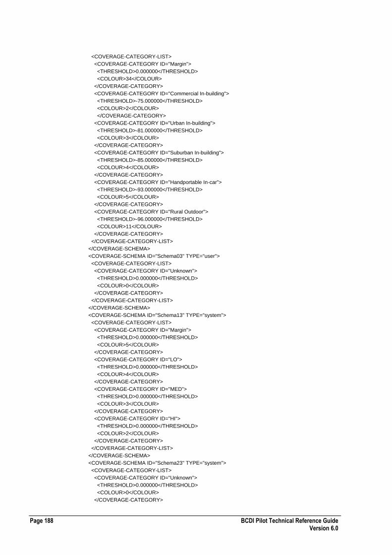
Page 188 BCDI Pilot Technical Reference Guide Version 6.0
<COVERAGE-CATEGORY-LIST>
<COVERAGE-CATEGORY ID="Margin">
<THRESHOLD>0.000000</THRESHOLD>
<COLOUR>34</COLOUR>
</COVERAGE-CATEGORY>
<COVERAGE-CATEGORY ID="Commercial In-building">
<THRESHOLD>-75.000000</THRESHOLD>
<COLOUR>2</COLOUR>
</COVERAGE-CATEGORY>
<COVERAGE-CATEGORY ID="Urban In-building">
<THRESHOLD>-81.000000</THRESHOLD>
<COLOUR>3</COLOUR>
</COVERAGE-CATEGORY>
<COVERAGE-CATEGORY ID="Suburban In-building">
<THRESHOLD>-85.000000</THRESHOLD>
<COLOUR>4</COLOUR>
</COVERAGE-CATEGORY>
<COVERAGE-CATEGORY ID="Handportable In-car">
<THRESHOLD>-93.000000</THRESHOLD>
<COLOUR>5</COLOUR>
</COVERAGE-CATEGORY>
<COVERAGE-CATEGORY ID="Rural Outdoor">
<THRESHOLD>-96.000000</THRESHOLD>
<COLOUR>11</COLOUR>
</COVERAGE-CATEGORY>
</COVERAGE-CATEGORY-LIST>
</COVERAGE-SCHEMA>
<COVERAGE-SCHEMA ID="Schema03" TYPE="user">
<COVERAGE-CATEGORY-LIST>
<COVERAGE-CATEGORY ID="Unknown">
<THRESHOLD>0.000000</THRESHOLD>
<COLOUR>0</COLOUR>
</COVERAGE-CATEGORY>
</COVERAGE-CATEGORY-LIST>
</COVERAGE-SCHEMA>
<COVERAGE-SCHEMA ID="Schema13" TYPE="system">
<COVERAGE-CATEGORY-LIST>
<COVERAGE-CATEGORY ID="Margin">
<THRESHOLD>0.000000</THRESHOLD>
<COLOUR>5</COLOUR>
</COVERAGE-CATEGORY>
<COVERAGE-CATEGORY ID="LO">
<THRESHOLD>0.000000</THRESHOLD>
<COLOUR>4</COLOUR>
</COVERAGE-CATEGORY>
<COVERAGE-CATEGORY ID="MED">
<THRESHOLD>0.000000</THRESHOLD>
<COLOUR>3</COLOUR>
</COVERAGE-CATEGORY>
<COVERAGE-CATEGORY ID="HI">
<THRESHOLD>0.000000</THRESHOLD>
<COLOUR>2</COLOUR>
</COVERAGE-CATEGORY>
</COVERAGE-CATEGORY-LIST>
</COVERAGE-SCHEMA>
<COVERAGE-SCHEMA ID="Schema23" TYPE="system">
<COVERAGE-CATEGORY-LIST>
<COVERAGE-CATEGORY ID="Unknown">
<THRESHOLD>0.000000</THRESHOLD>
<COLOUR>0</COLOUR>
</COVERAGE-CATEGORY>

BCDI Pilot Technical Reference Guide Page 189 Version 6.0
</COVERAGE-CATEGORY-LIST>
</COVERAGE-SCHEMA>
</COVERAGE-SCHEMA-LIST>
<IF-WEIGHT>Default</IF-WEIGHT>
<CHANNEL-TRX-MAP>Standard_AMPS</CHANNEL-TRX-MAP>
<SUPER>NO</SUPER>
</CELL-LAYER>
</CELL-LAYER-LIST>
UMTS Carrier XML Configuration File Format
The following table describes the XML configuration file format for UMTS carriers:
Required Tags ID attribute
Comments INDEX is the fixed carrier identifier, 0 represents the first carrier, 1 represents the second carrier and so on.
CARRIER-ADJACENCY ADJACENT CARRIER as for INDEX, but -1 indicates the carrier is not selected' as an adjacent carrier.
Enumerated Values INDEX
[0| 1| ... |31]
CARRIER-ADJACENCY ADJACENT-CARRIER
[-1| 0| 1| ... |31]
Example UMTS Carrier XML Configuration File
The following section of code shows an example UMTS carrier XML configuration file: <?xml version="1.0" ?>
<CARRIER-UMTS-LIST ENTERPRISE-XML-VERSION="3">
<UMTS-CARRIER ID="Macrocell 1">
<SECURITY-RO>
<OWNER>Administrator</OWNER>
<GROUP>All</GROUP>
<CREATED>2006-09-11 14:05:24 Administrator</CREATED>
<MODIFIED>2006-09-13 15:23:05 demouser</MODIFIED>
</SECURITY-RO>
<INDEX>0</INDEX>
<UPLINK-CH>0</UPLINK-CH>
<DOWNLINK-CH>0</DOWNLINK-CH>
<CARRIER-PRIORITY>0</CARRIER-PRIORITY>
<BANDWIDTH>3.500000</BANDWIDTH>
<FREQUENCY>3500.000000</FREQUENCY>
<CARRIER-ADJACENCIES>
<CARRIER-ADJACENCY ADJACENT-CARRIER="-1" INDEX="0" UL-ATTENUATION="33." DL-ATTENUATION="33." />
<CARRIER-ADJACENCY ADJACENT-CARRIER="-1" INDEX="1" UL-ATTENUATION="33." DL-ATTENUATION="33." />
<CARRIER-ADJACENCY ADJACENT-CARRIER="-1" INDEX="2" UL-ATTENUATION="33." DL-ATTENUATION="33." />
<CARRIER-ADJACENCY ADJACENT-CARRIER="-1" INDEX="3" UL-ATTENUATION="33." DL-ATTENUATION="33." />
<CARRIER-ADJACENCY ADJACENT-CARRIER="-1" INDEX="4" UL-ATTENUATION="33." DL-ATTENUATION="33." />
<CARRIER-ADJACENCY ADJACENT-CARRIER="-1" INDEX="5" UL-ATTENUATION="33." DL-ATTENUATION="33." />
<CARRIER-ADJACENCY ADJACENT-CARRIER="-1" INDEX="6" UL-ATTENUATION="33." DL-ATTENUATION="33." />

Page 190 BCDI Pilot Technical Reference Guide Version 6.0
<CARRIER-ADJACENCY ADJACENT-CARRIER="-1" INDEX="7" UL-ATTENUATION="33." DL-ATTENUATION="33." />
<CARRIER-ADJACENCY ADJACENT-CARRIER="-1" INDEX="8" UL-ATTENUATION="33." DL-ATTENUATION="33." />
<CARRIER-ADJACENCY ADJACENT-CARRIER="-1" INDEX="9" UL-ATTENUATION="33." DL-ATTENUATION="33." />
<CARRIER-ADJACENCY ADJACENT-CARRIER="-1" INDEX="10" UL-ATTENUATION="33." DL-ATTENUATION="33." />
<CARRIER-ADJACENCY ADJACENT-CARRIER="-1" INDEX="11" UL-ATTENUATION="33." DL-ATTENUATION="33." />
<CARRIER-ADJACENCY ADJACENT-CARRIER="-1" INDEX="12" UL-ATTENUATION="33." DL-ATTENUATION="33." />
<CARRIER-ADJACENCY ADJACENT-CARRIER="-1" INDEX="13" UL-ATTENUATION="33." DL-ATTENUATION="33." />
<CARRIER-ADJACENCY ADJACENT-CARRIER="-1" INDEX="14" UL-ATTENUATION="33." DL-ATTENUATION="33." />
<CARRIER-ADJACENCY ADJACENT-CARRIER="-1" INDEX="15" UL-ATTENUATION="33." DL-ATTENUATION="33." />
<CARRIER-ADJACENCY ADJACENT-CARRIER="-1" INDEX="16" UL-ATTENUATION="33." DL-ATTENUATION="33." />
<CARRIER-ADJACENCY ADJACENT-CARRIER="-1" INDEX="17" UL-ATTENUATION="33." DL-ATTENUATION="33." />
<CARRIER-ADJACENCY ADJACENT-CARRIER="-1" INDEX="18" UL-ATTENUATION="33." DL-ATTENUATION="33." />
<CARRIER-ADJACENCY ADJACENT-CARRIER="-1" INDEX="19" UL-ATTENUATION="33." DL-ATTENUATION="33." />
<CARRIER-ADJACENCY ADJACENT-CARRIER="-1" INDEX="20" UL-ATTENUATION="33." DL-ATTENUATION="33." />
<CARRIER-ADJACENCY ADJACENT-CARRIER="-1" INDEX="21" UL-ATTENUATION="33." DL-ATTENUATION="33." />
<CARRIER-ADJACENCY ADJACENT-CARRIER="-1" INDEX="22" UL-ATTENUATION="33." DL-ATTENUATION="33." />
<CARRIER-ADJACENCY ADJACENT-CARRIER="-1" INDEX="23" UL-ATTENUATION="33." DL-ATTENUATION="33." />
<CARRIER-ADJACENCY ADJACENT-CARRIER="-1" INDEX="24" UL-ATTENUATION="33." DL-ATTENUATION="33." />
<CARRIER-ADJACENCY ADJACENT-CARRIER="-1" INDEX="25" UL-ATTENUATION="33." DL-ATTENUATION="33." />
<CARRIER-ADJACENCY ADJACENT-CARRIER="-1" INDEX="26" UL-ATTENUATION="33." DL-ATTENUATION="33." />
<CARRIER-ADJACENCY ADJACENT-CARRIER="-1" INDEX="27" UL-ATTENUATION="33." DL-ATTENUATION="33." />
<CARRIER-ADJACENCY ADJACENT-CARRIER="-1" INDEX="28" UL-ATTENUATION="33." DL-ATTENUATION="33." />
<CARRIER-ADJACENCY ADJACENT-CARRIER="-1" INDEX="29" UL-ATTENUATION="33." DL-ATTENUATION="33." />
<CARRIER-ADJACENCY ADJACENT-CARRIER="-1" INDEX="30" UL-ATTENUATION="33." DL-ATTENUATION="33." />
</CARRIER-ADJACENCIES>
</UMTS-CARRIER>
</CARRIER-UMTS-LIST>
Mobile WiMAX Carrier XML Configuration File Format
The following table describes the XML configuration file format for Mobile WiMAX carriers:
Required Tags ID attribute
Comments ADJACENT-CARRIER
Accepts -1 (No Carrier), then values 1(Carrier2) to 31 (Carrier32)
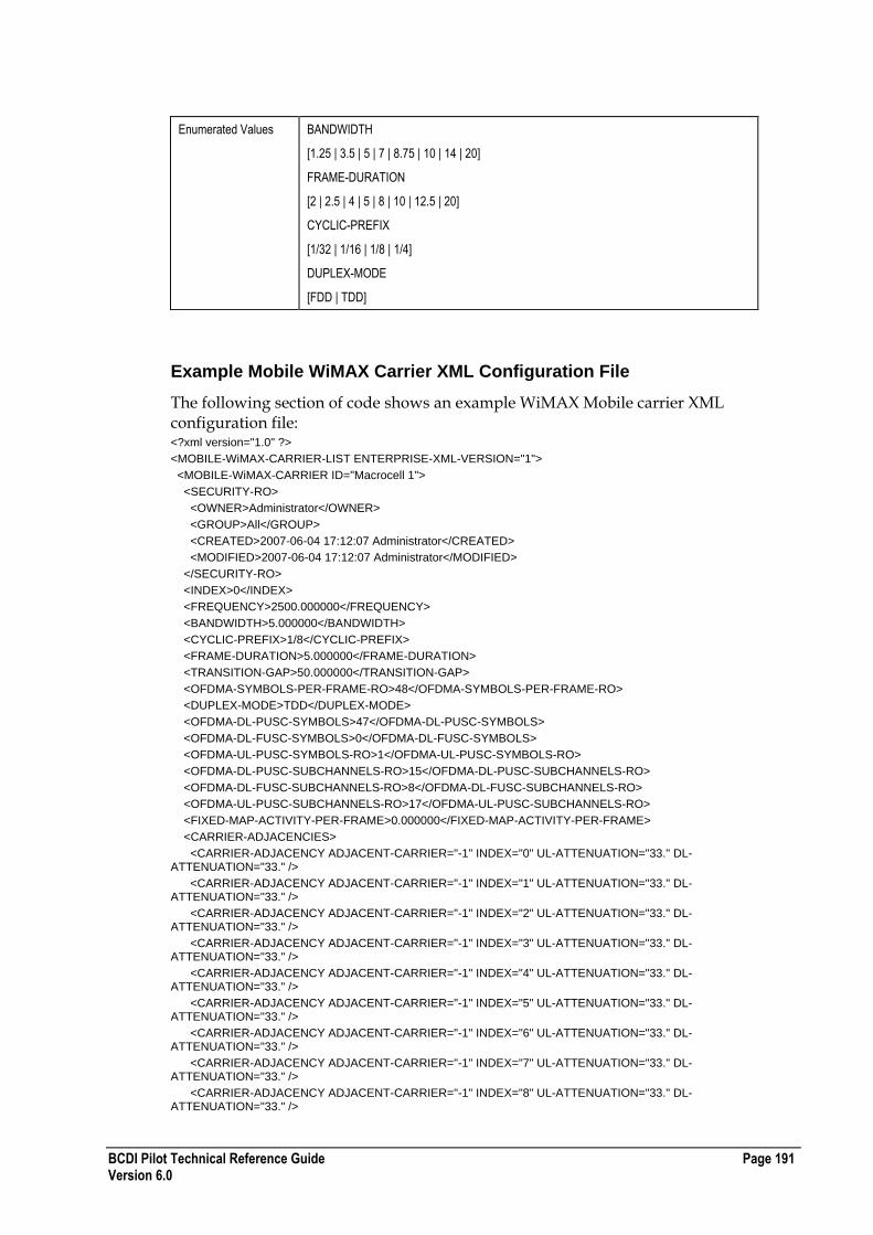
BCDI Pilot Technical Reference Guide Page 191 Version 6.0
Enumerated Values BANDWIDTH
[1.25 | 3.5 | 5 | 7 | 8.75 | 10 | 14 | 20]
FRAME-DURATION
[2 | 2.5 | 4 | 5 | 8 | 10 | 12.5 | 20]
CYCLIC-PREFIX
[1/32 | 1/16 | 1/8 | 1/4]
DUPLEX-MODE
[FDD | TDD]
Example Mobile WiMAX Carrier XML Configuration File
The following section of code shows an example WiMAX Mobile carrier XML configuration file: <?xml version="1.0" ?>
<MOBILE-WiMAX-CARRIER-LIST ENTERPRISE-XML-VERSION="1">
<MOBILE-WiMAX-CARRIER ID="Macrocell 1">
<SECURITY-RO>
<OWNER>Administrator</OWNER>
<GROUP>All</GROUP>
<CREATED>2007-06-04 17:12:07 Administrator</CREATED>
<MODIFIED>2007-06-04 17:12:07 Administrator</MODIFIED>
</SECURITY-RO>
<INDEX>0</INDEX>
<FREQUENCY>2500.000000</FREQUENCY>
<BANDWIDTH>5.000000</BANDWIDTH>
<CYCLIC-PREFIX>1/8</CYCLIC-PREFIX>
<FRAME-DURATION>5.000000</FRAME-DURATION>
<TRANSITION-GAP>50.000000</TRANSITION-GAP>
<OFDMA-SYMBOLS-PER-FRAME-RO>48</OFDMA-SYMBOLS-PER-FRAME-RO>
<DUPLEX-MODE>TDD</DUPLEX-MODE>
<OFDMA-DL-PUSC-SYMBOLS>47</OFDMA-DL-PUSC-SYMBOLS>
<OFDMA-DL-FUSC-SYMBOLS>0</OFDMA-DL-FUSC-SYMBOLS>
<OFDMA-UL-PUSC-SYMBOLS-RO>1</OFDMA-UL-PUSC-SYMBOLS-RO>
<OFDMA-DL-PUSC-SUBCHANNELS-RO>15</OFDMA-DL-PUSC-SUBCHANNELS-RO>
<OFDMA-DL-FUSC-SUBCHANNELS-RO>8</OFDMA-DL-FUSC-SUBCHANNELS-RO>
<OFDMA-UL-PUSC-SUBCHANNELS-RO>17</OFDMA-UL-PUSC-SUBCHANNELS-RO>
<FIXED-MAP-ACTIVITY-PER-FRAME>0.000000</FIXED-MAP-ACTIVITY-PER-FRAME>
<CARRIER-ADJACENCIES>
<CARRIER-ADJACENCY ADJACENT-CARRIER="-1" INDEX="0" UL-ATTENUATION="33." DL-ATTENUATION="33." />
<CARRIER-ADJACENCY ADJACENT-CARRIER="-1" INDEX="1" UL-ATTENUATION="33." DL-ATTENUATION="33." />
<CARRIER-ADJACENCY ADJACENT-CARRIER="-1" INDEX="2" UL-ATTENUATION="33." DL-ATTENUATION="33." />
<CARRIER-ADJACENCY ADJACENT-CARRIER="-1" INDEX="3" UL-ATTENUATION="33." DL-ATTENUATION="33." />
<CARRIER-ADJACENCY ADJACENT-CARRIER="-1" INDEX="4" UL-ATTENUATION="33." DL-ATTENUATION="33." />
<CARRIER-ADJACENCY ADJACENT-CARRIER="-1" INDEX="5" UL-ATTENUATION="33." DL-ATTENUATION="33." />
<CARRIER-ADJACENCY ADJACENT-CARRIER="-1" INDEX="6" UL-ATTENUATION="33." DL-ATTENUATION="33." />
<CARRIER-ADJACENCY ADJACENT-CARRIER="-1" INDEX="7" UL-ATTENUATION="33." DL-ATTENUATION="33." />
<CARRIER-ADJACENCY ADJACENT-CARRIER="-1" INDEX="8" UL-ATTENUATION="33." DL-ATTENUATION="33." />

Page 192 BCDI Pilot Technical Reference Guide Version 6.0
<CARRIER-ADJACENCY ADJACENT-CARRIER="-1" INDEX="9" UL-ATTENUATION="33." DL-ATTENUATION="33." />
<CARRIER-ADJACENCY ADJACENT-CARRIER="-1" INDEX="10" UL-ATTENUATION="33." DL-ATTENUATION="33." />
<CARRIER-ADJACENCY ADJACENT-CARRIER="-1" INDEX="11" UL-ATTENUATION="33." DL-ATTENUATION="33." />
<CARRIER-ADJACENCY ADJACENT-CARRIER="-1" INDEX="12" UL-ATTENUATION="33." DL-ATTENUATION="33." />
<CARRIER-ADJACENCY ADJACENT-CARRIER="-1" INDEX="13" UL-ATTENUATION="33." DL-ATTENUATION="33." />
<CARRIER-ADJACENCY ADJACENT-CARRIER="-1" INDEX="14" UL-ATTENUATION="33." DL-ATTENUATION="33." />
<CARRIER-ADJACENCY ADJACENT-CARRIER="-1" INDEX="15" UL-ATTENUATION="33." DL-ATTENUATION="33." />
<CARRIER-ADJACENCY ADJACENT-CARRIER="-1" INDEX="16" UL-ATTENUATION="33." DL-ATTENUATION="33." />
<CARRIER-ADJACENCY ADJACENT-CARRIER="-1" INDEX="17" UL-ATTENUATION="33." DL-ATTENUATION="33." />
<CARRIER-ADJACENCY ADJACENT-CARRIER="-1" INDEX="18" UL-ATTENUATION="33." DL-ATTENUATION="33." />
<CARRIER-ADJACENCY ADJACENT-CARRIER="-1" INDEX="19" UL-ATTENUATION="33." DL-ATTENUATION="33." />
<CARRIER-ADJACENCY ADJACENT-CARRIER="-1" INDEX="20" UL-ATTENUATION="33." DL-ATTENUATION="33." />
<CARRIER-ADJACENCY ADJACENT-CARRIER="-1" INDEX="21" UL-ATTENUATION="33." DL-ATTENUATION="33." />
<CARRIER-ADJACENCY ADJACENT-CARRIER="-1" INDEX="22" UL-ATTENUATION="33." DL-ATTENUATION="33." />
<CARRIER-ADJACENCY ADJACENT-CARRIER="-1" INDEX="23" UL-ATTENUATION="33." DL-ATTENUATION="33." />
<CARRIER-ADJACENCY ADJACENT-CARRIER="-1" INDEX="24" UL-ATTENUATION="33." DL-ATTENUATION="33." />
<CARRIER-ADJACENCY ADJACENT-CARRIER="-1" INDEX="25" UL-ATTENUATION="33." DL-ATTENUATION="33." />
<CARRIER-ADJACENCY ADJACENT-CARRIER="-1" INDEX="26" UL-ATTENUATION="33." DL-ATTENUATION="33." />
<CARRIER-ADJACENCY ADJACENT-CARRIER="-1" INDEX="27" UL-ATTENUATION="33." DL-ATTENUATION="33." />
<CARRIER-ADJACENCY ADJACENT-CARRIER="-1" INDEX="28" UL-ATTENUATION="33." DL-ATTENUATION="33." />
<CARRIER-ADJACENCY ADJACENT-CARRIER="-1" INDEX="29" UL-ATTENUATION="33." DL-ATTENUATION="33." />
<CARRIER-ADJACENCY ADJACENT-CARRIER="-1" INDEX="30" UL-ATTENUATION="33." DL-ATTENUATION="33." />
</CARRIER-ADJACENCIES>
</MOBILE-WiMAX-CARRIER>
</MOBILE-WiMAX-CARRIER-LIST>
UMTS Resource XML Configuration File Format
The following table describes the XML configuration file format for UMTS resource:
Required Tags INDEX
Comments INDEX is the fixed resource identifier. 0 represents the first resource, 1 represents the second resource, and so on.
Enumerated Values INDEX
[0| 1| ... |5]
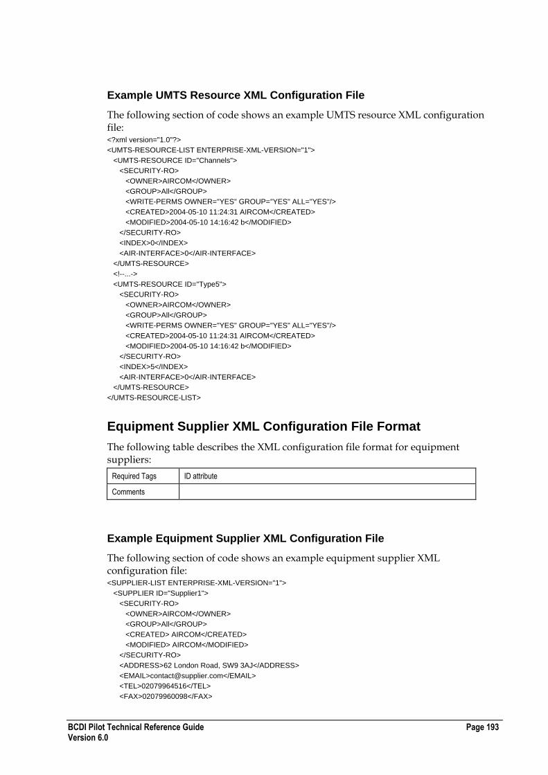
BCDI Pilot Technical Reference Guide Page 193 Version 6.0
Example UMTS Resource XML Configuration File
The following section of code shows an example UMTS resource XML configuration file: <?xml version="1.0"?>
<UMTS-RESOURCE-LIST ENTERPRISE-XML-VERSION="1">
<UMTS-RESOURCE ID="Channels">
<SECURITY-RO>
<OWNER>AIRCOM</OWNER>
<GROUP>All</GROUP>
<WRITE-PERMS OWNER="YES" GROUP="YES" ALL="YES"/>
<CREATED>2004-05-10 11:24:31 AIRCOM</CREATED>
<MODIFIED>2004-05-10 14:16:42 b</MODIFIED>
</SECURITY-RO>
<INDEX>0</INDEX>
<AIR-INTERFACE>0</AIR-INTERFACE>
</UMTS-RESOURCE>
<!--...->
<UMTS-RESOURCE ID="Type5">
<SECURITY-RO>
<OWNER>AIRCOM</OWNER>
<GROUP>All</GROUP>
<WRITE-PERMS OWNER="YES" GROUP="YES" ALL="YES"/>
<CREATED>2004-05-10 11:24:31 AIRCOM</CREATED>
<MODIFIED>2004-05-10 14:16:42 b</MODIFIED>
</SECURITY-RO>
<INDEX>5</INDEX>
<AIR-INTERFACE>0</AIR-INTERFACE>
</UMTS-RESOURCE>
</UMTS-RESOURCE-LIST>
Equipment Supplier XML Configuration File Format
The following table describes the XML configuration file format for equipment suppliers:
Required Tags ID attribute
Comments
Example Equipment Supplier XML Configuration File
The following section of code shows an example equipment supplier XML configuration file: <SUPPLIER-LIST ENTERPRISE-XML-VERSION="1">
<SUPPLIER ID="Supplier1">
<SECURITY-RO>
<OWNER>AIRCOM</OWNER>
<GROUP>All</GROUP>
<CREATED> AIRCOM</CREATED>
<MODIFIED> AIRCOM</MODIFIED>
</SECURITY-RO>
<ADDRESS>62 London Road, SW9 3AJ</ADDRESS>
<EMAIL>[email protected]</EMAIL>
<TEL>02079964516</TEL>
<FAX>02079960098</FAX>
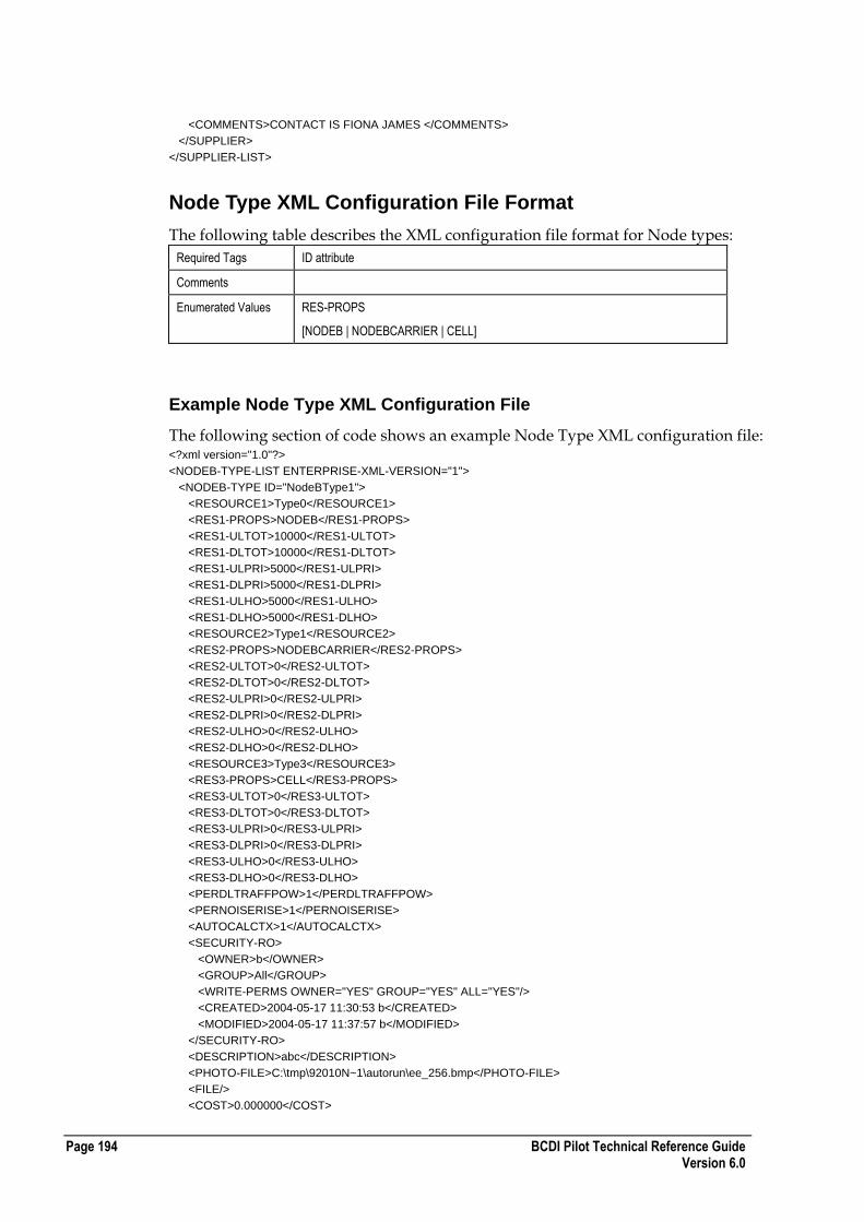
Page 194 BCDI Pilot Technical Reference Guide Version 6.0
<COMMENTS>CONTACT IS FIONA JAMES </COMMENTS>
</SUPPLIER>
</SUPPLIER-LIST>
Node Type XML Configuration File Format
The following table describes the XML configuration file format for Node types:
Required Tags ID attribute
Comments
Enumerated Values RES-PROPS
[NODEB | NODEBCARRIER | CELL]
Example Node Type XML Configuration File
The following section of code shows an example Node Type XML configuration file: <?xml version="1.0"?>
<NODEB-TYPE-LIST ENTERPRISE-XML-VERSION="1">
<NODEB-TYPE ID="NodeBType1">
<RESOURCE1>Type0</RESOURCE1>
<RES1-PROPS>NODEB</RES1-PROPS>
<RES1-ULTOT>10000</RES1-ULTOT>
<RES1-DLTOT>10000</RES1-DLTOT>
<RES1-ULPRI>5000</RES1-ULPRI>
<RES1-DLPRI>5000</RES1-DLPRI>
<RES1-ULHO>5000</RES1-ULHO>
<RES1-DLHO>5000</RES1-DLHO>
<RESOURCE2>Type1</RESOURCE2>
<RES2-PROPS>NODEBCARRIER</RES2-PROPS>
<RES2-ULTOT>0</RES2-ULTOT>
<RES2-DLTOT>0</RES2-DLTOT>
<RES2-ULPRI>0</RES2-ULPRI>
<RES2-DLPRI>0</RES2-DLPRI>
<RES2-ULHO>0</RES2-ULHO>
<RES2-DLHO>0</RES2-DLHO>
<RESOURCE3>Type3</RESOURCE3>
<RES3-PROPS>CELL</RES3-PROPS>
<RES3-ULTOT>0</RES3-ULTOT>
<RES3-DLTOT>0</RES3-DLTOT>
<RES3-ULPRI>0</RES3-ULPRI>
<RES3-DLPRI>0</RES3-DLPRI>
<RES3-ULHO>0</RES3-ULHO>
<RES3-DLHO>0</RES3-DLHO>
<PERDLTRAFFPOW>1</PERDLTRAFFPOW>
<PERNOISERISE>1</PERNOISERISE>
<AUTOCALCTX>1</AUTOCALCTX>
<SECURITY-RO>
<OWNER>b</OWNER>
<GROUP>All</GROUP>
<WRITE-PERMS OWNER="YES" GROUP="YES" ALL="YES"/>
<CREATED>2004-05-17 11:30:53 b</CREATED>
<MODIFIED>2004-05-17 11:37:57 b</MODIFIED>
</SECURITY-RO>
<DESCRIPTION>abc</DESCRIPTION>
<PHOTO-FILE>C:\tmp\92010N~1\autorun\ee_256.bmp</PHOTO-FILE>
<FILE/>
<COST>0.000000</COST>

BCDI Pilot Technical Reference Guide Page 195 Version 6.0
<WEIGHT>0.000000</WEIGHT>
<ICON/>
<SUPPLIER>Supplier Name</SUPPLIER>
</NODEB-TYPE>
</NODEB-TYPE-LIST>
CDMA Carrier XML Configuration File Format
The following table describes the XML configuration file format for CDMA carriers:
Required Tags ID attribute
Comments The narrow band carriers will have a ID value of 0..23, while the wide band carriers will have a ID value of 24..31.
1..32 <CARRIER-CDMA2000> elements can exists.
Enumerated Values None
Example CDMA Carrier XML Configuration File
The following section of code shows an example CDMA carrier XML configuration file: <?xml version="1.0"?>
<CARRIER-CDMA-LIST ENTERPRISE-XML-VERSION="2">
<CARRIER-CDMA ID="0">
<SECURITY-RO>
<OWNER>AIRCOM</OWNER>
<GROUP>All</GROUP>
<WRITE-PERMS OWNER="NO" GROUP="NO" ALL="YES"/>
<CREATED>2004-05-10 11:24:31 AIRCOM</CREATED>
<MODIFIED>2004-05-10 14:16:42 b</MODIFIED>
</SECURITY-RO>
<CARRIER_NAME>CDMA Channel 1</CARRIER_NAME>
<FWD-LINK-CAR>0.000000</FWD-LINK-CAR>
<REV-LINK-CAR>0.000000</REV-LINK-CAR>
<LEFT-NBR-UL-DB>33.000000</LEFT-NBR-UL-DB>
<LEFT-NBR-DL-DB>33.000000</LEFT-NBR-DL-DB>
<RIGHT-NBR-UL-DB>33.000000</RIGHT-NBR-UL-DB>
<RIGHT-NBR-DL-DB>33.000000</RIGHT-NBR-DL-DB>
<LEFT-NBR-CAR>-1</LEFT-NBR-CAR>
<RIGHT-NBR-CAR>-1</RIGHT-NBR-CAR>
<CARRIER-PRIORITY>0</CARRIER-PRIORITY>
</CARRIER-CDMA>
<!--...-->
<CARRIER-CDMA ID="31">
<SECURITY-RO>
<OWNER>AIRCOM</OWNER>
<GROUP>All</GROUP>
<WRITE-PERMS OWNER="NO" GROUP="NO" ALL="YES"/>
<CREATED>2004-05-10 11:24:31 AIRCOM</CREATED>
<MODIFIED>2004-05-10 14:16:43 b</MODIFIED>
</SECURITY-RO>
<CARRIER_NAME>CDMA Channel 23W</CARRIER_NAME>
<FWD-LINK-CAR>0.000000</FWD-LINK-CAR>
<REV-LINK-CAR>0.000000</REV-LINK-CAR>
<LEFT-NBR-UL-DB>33.000000</LEFT-NBR-UL-DB>
<LEFT-NBR-DL-DB>33.000000</LEFT-NBR-DL-DB>
<RIGHT-NBR-UL-DB>33.000000</RIGHT-NBR-UL-DB>
<RIGHT-NBR-DL-DB>33.000000</RIGHT-NBR-DL-DB>

Page 196 BCDI Pilot Technical Reference Guide Version 6.0
<LEFT-NBR-CAR>-1</LEFT-NBR-CAR>
<RIGHT-NBR-CAR>-1</RIGHT-NBR-CAR>
<CARRIER-PRIORITY>0</CARRIER-PRIORITY>
</CARRIER-CDMA>
</CARRIER-CDMA-LIST>
Band Channels XML Configuration File Format
The following table describes the XML configuration file format for bands channels:
Required Tags ID attribute
NAME element
LO-FREQ element
Comments FREQ values must be between 400MHz and 350,000MHz
Channel LO-FREQ‟s must be unique within each band
Channel NAME‟s must be unique within band
Enumerated Values None
Example Band Channels XML Configuration File
The following section of code shows an example band channels XML configuration file: <BAND-LIST ENTERPRISE-XML-VERSION="1">
<BAND ID="High Band">
<SECURITY-RO>
<OWNER>b</OWNER>
<GROUP>All</GROUP>
<WRITE-PERMS OWNER="YES" GROUP="YES" ALL="YES" />
<CREATED>2004-05-10 14:16:43 b</CREATED>
<MODIFIED>2004-05-10 14:16:43 b</MODIFIED>
</SECURITY-RO>
<CHANNEL-LIST>
<CHANNEL>
<NAME>Channel 2</NAME>
<LO-FREQ>14000.00</LO-FREQ>
<HI-FREQ>15000.00</HI-FREQ>
</CHANNEL>
<CHANNEL>
<NAME>Channel 3</NAME>
<LO-FREQ>16000.00</LO-FREQ>
<HI-FREQ>17000.00</HI-FREQ>
</CHANNEL>
<CHANNEL>
<NAME>Channel 4</NAME>
<LO-FREQ>12000.00</LO-FREQ>
<HI-FREQ>13000.00</HI-FREQ>
</CHANNEL>
</CHANNEL-LIST>
<WIDTH>1.50</WIDTH>
</BAND>
</BAND-LIST>

BCDI Pilot Technical Reference Guide Page 197 Version 6.0
Contact Person XML Configuration File Format
The following table describes the XML configuration file format for contact person:
Required Tags ID attribute (Surname of the contact)
Comments TEL and FAX elements can appear as many times as required and should not contain white space.
Example Contact Person XML Configuration File
The following section of code shows an example contact person XML configuration file: <?xml version="1.0" ?>
<CONTACT-LIST ENTERPRISE-XML-VERSION="2">
<CONTACT ID="Dobson">
<SECURITY-RO>
<OWNER>admin</OWNER>
<GROUP>All</GROUP>
<CREATED>admin</CREATED>
<MODIFIED>admin</MODIFIED>
</SECURITY-RO>
<TITLE>Mr</TITLE>
<FORENAME>Steve</FORENAME>
<COMPANY>CellQuip Ltd</COMPANY>
<COMMENTS>Sales Manager</COMMENTS>
<TEL-LIST>
<TEL>01737123456</TEL>
</TEL-LIST>
<FAX-LIST>
<FAX>01737654321</FAX>
</FAX-LIST>
</CONTACT>
</CONTACT-LIST
Antenna XML Configuration File Format
The following table describes the XML configuration file format for antennas:
Required Tags ID attribute
Comments Antenna mask angles omitted will not be altered.
An antenna mask element should contain a comma-delimited pair of numbers as so:
<M> AZIMUTH, GAIN </M>
FREQUENCY is in MHz.
Enumerated Values TILT-TYPE
[ELECTRICAL | MECHANICAL]
POLARISATION
[HORIZONTAL | VERTICAL | CROSSPOLAR]
UNIQUE-ID-MODE
[MANUAL | AUTOMATIC]

Page 198 BCDI Pilot Technical Reference Guide Version 6.0
Example Antenna XML Configuration File
The following section of code shows part of an example Antenna XML configuration file: <?xml version="1.0" ?>
ANTENNA-LIST ENTERPRISE-XML-VERSION="3">
<ANTENNA ID="65_4_12.5_XJ_900">
<SWITCHED-BEAM>NO</SWITCHED-BEAM>
<NUM-PATTERNS-RO>1</NUM-PATTERNS-RO>
<MANUFACTURER>Jaybeam 7600</MANUFACTURER>
<FOLDER-PATH />
<SECURITY-RO>
<OWNER>ent5123user</OWNER>
<GROUP>All</GROUP>
<CREATED>2005-11-23 18:59:41 ent5123user</CREATED>
<MODIFIED>2005-11-23 18:59:41 ent5123user</MODIFIED>
</SECURITY-RO>
<DESCRIPTION>4 degree elec. tilted Crossed Polarised Antenna</DESCRIPTION>
<PHOTO-FILE />
<FILE />
<COST>0.000000</COST>
<WEIGHT>0.000000</WEIGHT>
<ICON />
<SUPPLIER />
<BEAM-PATTERN-LIST>
<BEAM-PATTERN ID="65_4_12.5_XJ_900" UNIQUE-ID-MODE="AUTOMATIC" UNIQUE-ID="65_4_12.5_XJ_900\65_4_12.5_XJ_900">
<DESCRIPTION>4 degree elec. tilted Crossed Polarised Antenna</DESCRIPTION>
<ELEC_TILT>4.000000</ELEC_TILT>
<EL-ARR-INDX>0</EL-ARR-INDX>
<CFG-ID />
<ELEC-BEAM-ADJ>1</ELEC-BEAM-ADJ>
<HORIZONTAL-BW>62.000000</HORIZONTAL-BW>
<VERTICAL-BW>9.000000</VERTICAL-BW>
<SWB-ROTATION-ANGLE>0.000000</SWB-ROTATION-ANGLE>
<SWB-BROADCAST>NO</SWB-BROADCAST>
<GAIN>13.200000</GAIN>
<GAIN-TYPE>dBD</GAIN-TYPE>
<FREQUENCY>870.000000</FREQUENCY>
<TILT-TYPE>MECHANICAL</TILT-TYPE>
<FRONT-TO-BACK>30.000000</FRONT-TO-BACK>
<CROSS-POLAR-DISC>0.000000</CROSS-POLAR-DISC>
<POLARISATION>VERTICAL</POLARISATION>
<H-MASK-LIST>
<M>0.00,0.0000</M>
<...>
<M>359.50,0.0000</M>
</H-MASK-LIST>
<V-MASK-LIST>
<M>0.00,2.2000</M>
<...>
<M>359.50,2.9000</M>
</V-MASK-LIST>
</BEAM-PATTERN>
</BEAM-PATTERN-LIST>
</ANTENNA>
</ANTENNA-LIST>

BCDI Pilot Technical Reference Guide Page 199 Version 6.0
BTS Type XML Configuration File Format
The following table describes the XML configuration file format for BTS types:
Required Tags ID attribute
Comments TX-POWER-MIN and TX-POWER-MAX values in dBm
Enumerated Values None
Example BTS Type XML Configuration File
The following section of code shows an example BTS type XML configuration file: <?xml version="1.0"?>
<BTS-LIST ENTERPRISE-XML-VERSION="1">
<BTS ID="BTS0">
<TX-POWER-MIN>0.000000</TX-POWER-MIN>
<TX-POWER-MAX>100.000000</TX-POWER-MAX>
<TX-POWER-STEP>1.000000</TX-POWER-STEP>
<SITE-SPACING>0</SITE-SPACING>
<CELL-SPACING>1</CELL-SPACING>
<POWER-LIST>
<PWR-NODE>GSM-Default, 0.00, 100.00</PWR-NODE>
</POWER-LIST>
<SECURITY-RO>
<OWNER>b</OWNER>
<GROUP>All</GROUP>
<CREATED>2004-05-10 17:02:43 b</CREATED>
<MODIFIED>2004-05-10 17:02:43 b</MODIFIED>
</SECURITY-RO>
<DESCRIPTION/>
<PHOTO-FILE/>
<FILE/>
<COST>0.000000</COST>
<WEIGHT>0.000000</WEIGHT>
<ICON/>
<SUPPLIER/>
</BTS>
</BTS-LIST>
Cabin XML Configuration File Format
The following table describes the XML configuration file format for cabins:
Required Tags ID attribute
Comments LENGTH, WIDTH and HEIGHT in metres
Enumerated Values None
Example Cabin XML Configuration File
The following section of code shows an example cabin XML configuration file: <CABIN-LIST ENTERPRISE-XML-VERSION="1">
<CABIN ID="Cabin2">
<LENGTH>3.000000</LENGTH>
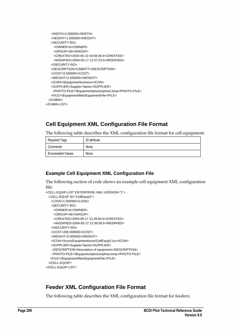
Page 200 BCDI Pilot Technical Reference Guide Version 6.0
<WIDTH>2.000000</WIDTH>
<HEIGHT>1.000000</HEIGHT>
<SECURITY-RO>
<OWNER>b</OWNER>
<GROUP>All</GROUP>
<CREATED>2004-05-10 16:58:39 b</CREATED>
<MODIFIED>2004-05-17 12:37:23 b</MODIFIED>
</SECURITY-RO>
<DESCRIPTION>CABINTT</DESCRIPTION>
<COST>0.000000</COST>
<WEIGHT>2.500000</WEIGHT>
<ICON>\\Equipment\Iconsico</ICON>
<SUPPLIER>Supplier Name</SUPPLIER>
<PHOTO-FILE>\\Equipment\photos\photo.bmp</PHOTO-FILE>
<FILE>\\Equipment\files\EquipmentFile</FILE>
</CABIN>
</CABIN-LIST>
Cell Equipment XML Configuration File Format
The following table describes the XML configuration file format for cell equipment:
Required Tags ID attribute
Comments None
Enumerated Values None
Example Cell Equipment XML Configuration File
The following section of code shows an example cell equipment XML configuration file: <CELL-EQUIP-LIST ENTERPRISE-XML-VERSION="1">
<CELL-EQUIP ID="CellEquip2">
<LOSS>1.000000</LOSS>
<SECURITY-RO>
<OWNER>b</OWNER>
<GROUP>All</GROUP>
<CREATED>2004-05-17 12:39:50 b</CREATED>
<MODIFIED>2004-05-17 12:39:58 b</MODIFIED>
</SECURITY-RO>
<COST>200.000000</COST>
<WEIGHT>0.000000</WEIGHT>
<ICON>\\Icons\EquipmentIcons\CellEquip2.ico</ICON>
<SUPPLIER>Supplier Name</SUPPLIER>
<DESCRIPTION>Description of equipment</DESCRIPTION>
<PHOTO-FILE>\\Equipment\photos\photo.bmp</PHOTO-FILE>
<FILE>\\Equipment\files\EquipmentFile</FILE>
</CELL-EQUIP>
</CELL-EQUIP-LIST>
Feeder XML Configuration File Format
The following table describes the XML configuration file format for feeders:

BCDI Pilot Technical Reference Guide Page 201 Version 6.0
Required Tags ID attribute
Comments None
Enumerated Values None
Example Feeder XML Configuration File
The following section of code shows an example feeder XML configuration file: <FEEDER-LIST ENTERPRISE-XML-VERSION="1">
<FEEDER ID="Feeder-900">
<LINEAR-LOSS>0.000000</LINEAR-LOSS>
<FREQUENCY>900.000000</FREQUENCY>
<CONNECTOR-LOSS>0.000000</CONNECTOR-LOSS>
<SECURITY-RO>
<OWNER>b</OWNER>
<GROUP>All</GROUP>
<CREATED>2004-05-10 16:58:35 b</CREATED>
<MODIFIED>2004-05-10 16:58:35 b</MODIFIED>
</SECURITY-RO>
<COST>0.000000</COST>
<WEIGHT>0.000000</WEIGHT>
<ICON>\\Icons\EquipmentIcons\ Feeder-900.ico</ICON>
<SUPPLIER>Supplier Name</SUPPLIER>
<DESCRIPTION>Description of equipment</DESCRIPTION>
<PHOTO-FILE>\\Equipment\photos\photo.bmp</PHOTO-FILE>
<FILE>\\Equipment\files\EquipmentFile</FILE>
</FEEDER>
</FEEDER-LIST>
Link Term Equipment XML Configuration File Format
The following table describes the XML configuration file format for link terminal equipment:
Required Tags ID attribute
Comments None
Enumerated Values None
Example Link Term Equipment XML Configuration File
The following section of code shows an example link terminal equipment XML configuration file: ?xml version="1.0"?>
<LINK-TERMINAL-LIST ENTERPRISE-XML-VERSION="1">
<LINK-TERMINAL ID="TermEquip2">
<MANUFACTURER>abc</MANUFACTURER>
<INPUT-TYPE>Input</INPUT-TYPE>
<OUTPUT-TYPE>Output</OUTPUT-TYPE>
<SECURITY-RO>
<OWNER>b</OWNER>
<GROUP>All</GROUP>
<CREATED>2004-05-17 12:46:33 b</CREATED>
<MODIFIED>2004-05-17 12:47:09 b</MODIFIED>
</SECURITY-RO>

Page 202 BCDI Pilot Technical Reference Guide Version 6.0
<DESCRIPTION>abc</DESCRIPTION>
<PHOTO-FILE>C:\tmp\92010N~1\autorun\cli_16.bmp</PHOTO-FILE>
<FILE/>
<COST>0.000000</COST>
<WEIGHT>0.000000</WEIGHT>
<ICON/>
<SUPPLIER>Supplier Name</SUPPLIER>
</LINK-TERMINAL>
</LINK-TERMINAL-LIST>
Link Type XML Configuration File Format
The following table describes the XML configuration file format for link types:
Required Tags ID attribute
Comments None
Enumerated Values BEARER
[Microwave | Fibre Optic | Copper | Satellite]
Example Link Type XML Configuration File
The following section of code shows an example link types XML configuration file: <?xml version="1.0" ?>
<LINK-TYPE-LIST ENTERPRISE-XML-VERSION="1">
<LINK-TYPE ID="Microwave 2E1">
<BEARER>Microwave</BEARER>
<NUMBER-FIBRE>0</NUMBER-FIBRE>
<COMMENTS />
<MANUFACTURER />
<INSTALL-COST>0.000000</INSTALL-COST>
<MAINTENANCE-COST>0.000000</MAINTENANCE-COST>
<LINEAR-RENTAL-COST>0.000000</LINEAR-RENTAL-COST>
<SECURITY-RO>
<OWNER>demouser</OWNER>
<GROUP>All</GROUP>
<WRITE-PERMS OWNER="YES" GROUP="NO" ALL="NO" />
<CREATED>2006-09-13 15:23:09 demouser</CREATED>
<MODIFIED>2006-09-13 15:23:09 demouser</MODIFIED>
</SECURITY-RO>
<DESCRIPTION />
<PHOTO-FILE />
<FILE />
<COST>0.000000</COST>
<WEIGHT>0.000000</WEIGHT>
<ICON />
<SUPPLIER />
</LINK-TYPE>
Mast XML Configuration File Format
The following table describes the XML configuration file format for masts:
Required Tags ID attribute
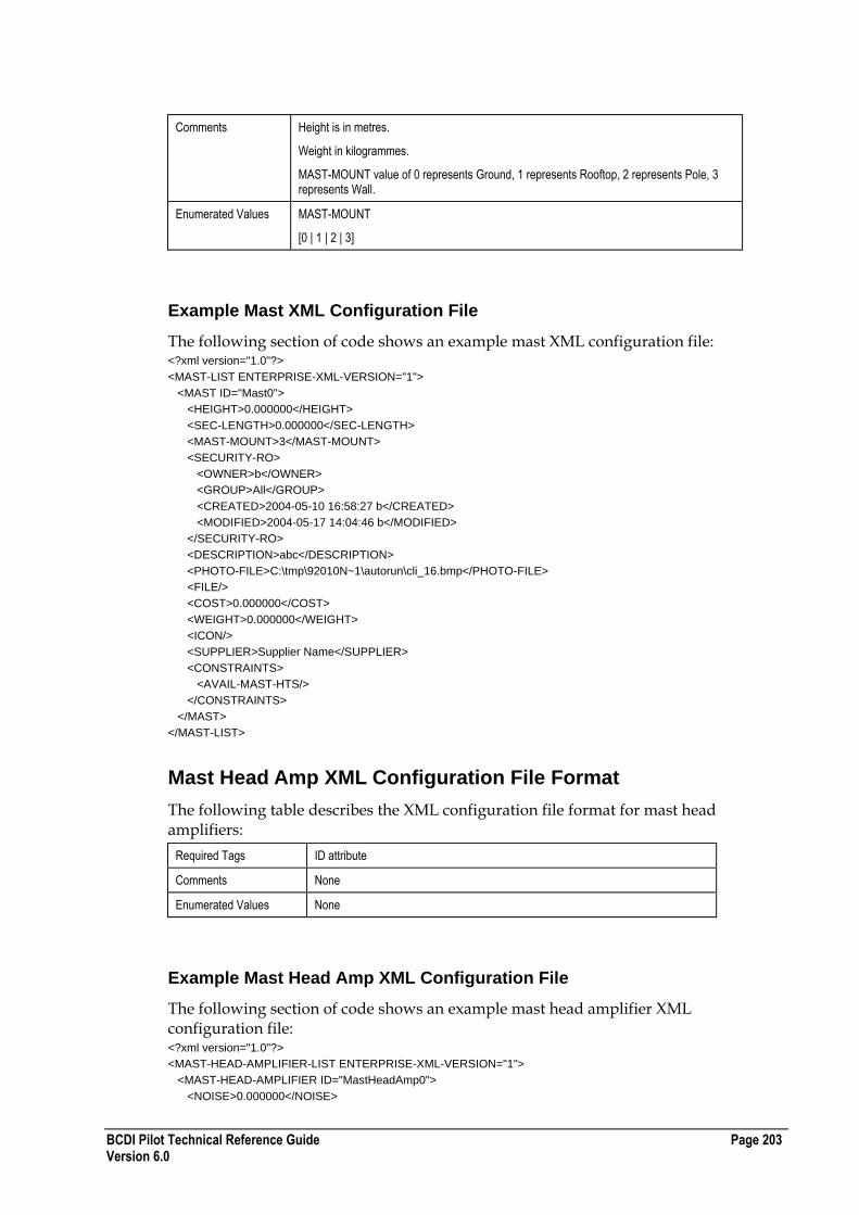
BCDI Pilot Technical Reference Guide Page 203 Version 6.0
Comments Height is in metres.
Weight in kilogrammes.
MAST-MOUNT value of 0 represents Ground, 1 represents Rooftop, 2 represents Pole, 3 represents Wall.
Enumerated Values MAST-MOUNT
[0 | 1 | 2 | 3]
Example Mast XML Configuration File
The following section of code shows an example mast XML configuration file: <?xml version="1.0"?>
<MAST-LIST ENTERPRISE-XML-VERSION="1">
<MAST ID="Mast0">
<HEIGHT>0.000000</HEIGHT>
<SEC-LENGTH>0.000000</SEC-LENGTH>
<MAST-MOUNT>3</MAST-MOUNT>
<SECURITY-RO>
<OWNER>b</OWNER>
<GROUP>All</GROUP>
<CREATED>2004-05-10 16:58:27 b</CREATED>
<MODIFIED>2004-05-17 14:04:46 b</MODIFIED>
</SECURITY-RO>
<DESCRIPTION>abc</DESCRIPTION>
<PHOTO-FILE>C:\tmp\92010N~1\autorun\cli_16.bmp</PHOTO-FILE>
<FILE/>
<COST>0.000000</COST>
<WEIGHT>0.000000</WEIGHT>
<ICON/>
<SUPPLIER>Supplier Name</SUPPLIER>
<CONSTRAINTS>
<AVAIL-MAST-HTS/>
</CONSTRAINTS>
</MAST>
</MAST-LIST>
Mast Head Amp XML Configuration File Format
The following table describes the XML configuration file format for mast head amplifiers:
Required Tags ID attribute
Comments None
Enumerated Values None
Example Mast Head Amp XML Configuration File
The following section of code shows an example mast head amplifier XML configuration file: <?xml version="1.0"?>
<MAST-HEAD-AMPLIFIER-LIST ENTERPRISE-XML-VERSION="1">
<MAST-HEAD-AMPLIFIER ID="MastHeadAmp0">
<NOISE>0.000000</NOISE>

Page 204 BCDI Pilot Technical Reference Guide Version 6.0
<MAX-GAIN>0.000000</MAX-GAIN>
<INSERTION-LOSS>0.000000</INSERTION-LOSS>
<SECURITY-RO>
<OWNER>b</OWNER>
<GROUP>All</GROUP>
<CREATED>2004-05-10 15:26:33 b</CREATED>
<MODIFIED>2004-05-10 15:26:33 b</MODIFIED>
</SECURITY-RO>
<DESCRIPTION/>
<PHOTO-FILE/>
<FILE/>
<COST>0.000000</COST>
<WEIGHT>0.000000</WEIGHT>
<ICON/>
<SUPPLIER/>
</MAST-HEAD-AMPLIFIER>
</MAST-HEAD-AMPLIFIER-LIST>
MW Antenna XML Configuration File Format
The following table describes the XML configuration file format for MW antennas:
Required Tags ID attribute
Comments As per Antenna
MIN-OPERATING-FREQ and MAX-OPERATING-FREQ are in MHz
Enumerated Values GAIN-TYPE
[dBD | dBI]
TILT-TYPE
[ELECTRICAL | MECHANICAL]
POLARISATION
[HORIZONTAL | VERTICAL | CROSSPOLAR]
POLARISATION-SUPPORT
[VERTICAL|HORIZONTAL|HORIZONTAL-VERTICAL|DUAL]
MASK-STYLE
[Symmetrical|NonSymmetrical]
PATTERN type
[Symmetrical|NonSymmetrical]
PATTERN pol
[VV|VH|HV|HH]
MASK type
[Plan|Side|Sym]
Example MW Antenna XML Configuration File
The following section of code shows an example MW antenna XML configuration file: <?xml version="1.0" ?>
<MW-ANTENNA-LIST ENTERPRISE-XML-VERSION="3">
<MW-ANTENNA ID="13_GHz/0.6m">
<GAIN>35.500000</GAIN>
<GAIN-TYPE>dBI</GAIN-TYPE>

BCDI Pilot Technical Reference Guide Page 205 Version 6.0
<FREQUENCY>13000.000000</FREQUENCY>
<TILT-TYPE>ELECTRICAL</TILT-TYPE>
<FRONT-TO-BACK>61.000000</FRONT-TO-BACK>
<CROSS-POLAR-DISC>0.000000</CROSS-POLAR-DISC>
<POLARISATION>VERTICAL</POLARISATION>
<SECURITY-RO>
<OWNER>ent610user</OWNER>
<GROUP>All</GROUP>
<WRITE-PERMS OWNER="YES" GROUP="NO" ALL="NO" />
<CREATED>2007-05-14 15:03:49 ent610user</CREATED>
<MODIFIED>2007-05-21 16:47:51 ent610user</MODIFIED>
</SECURITY-RO>
<DESCRIPTION>VHLP2-130, SINGLE POLARISATION</DESCRIPTION>
<PHOTO-FILE />
<FILE />
<COST>13000.000000</COST>
<WEIGHT>0.000000</WEIGHT>
<ICON />
<SUPPLIER />
<MIN-OPERATING-FREQ>12700.000000</MIN-OPERATING-FREQ>
<MAX-OPERATING-FREQ>13250.000000</MAX-OPERATING-FREQ>
<DIAMETER>0.600000</DIAMETER>
<POLARISATION-SUPPORT>Horizontal_Vertical</POLARISATION-SUPPORT>
<MASK-STYLE>NonSymmetrical</MASK-STYLE>
<PATTERN-LIST>
<PATTERN type="NonSymmetrical" pol="HH">
<MASK type="Plan">
<MASKDATA angle="0.00" loss="0.00" />
<MASKDATA angle="180.00" loss="0.00" />
</MASK>
<MASK type="Side">
<MASKDATA angle="0.00" loss="0.00" />
<MASKDATA angle="180.00" loss="0.00" />
</MASK>
</PATTERN>
<PATTERN type="NonSymmetrical" pol="HV">
<MASK type="Plan">
<MASKDATA angle="0.00" loss="0.00" />
<MASKDATA angle="180.00" loss="0.00" />
</MASK>
<MASK type="Side">
<MASKDATA angle="0.00" loss="0.00" />
<MASKDATA angle="180.00" loss="0.00" />
</MASK>
</PATTERN>
<PATTERN type="NonSymmetrical" pol="VV">
<MASK type="Plan">
<MASKDATA angle="0.00" loss="0.00" />
<MASKDATA angle="180.00" loss="0.00" />
</MASK>
<MASK type="Side">
<MASKDATA angle="0.00" loss="0.00" />
<MASKDATA angle="180.00" loss="0.00" />
</MASK>
</PATTERN>
<PATTERN type="NonSymmetrical" pol="VH">
<MASK type="Plan">
<MASKDATA angle="0.00" loss="0.00" />
<MASKDATA angle="180.00" loss="0.00" />
</MASK>
<MASK type="Side">
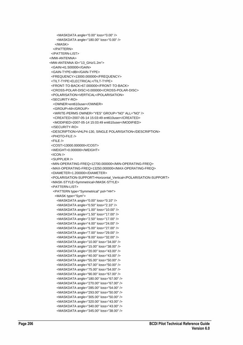
Page 206 BCDI Pilot Technical Reference Guide Version 6.0
<MASKDATA angle="0.00" loss="0.00" />
<MASKDATA angle="180.00" loss="0.00" />
</MASK>
</PATTERN>
</PATTERN-LIST>
</MW-ANTENNA>
<MW-ANTENNA ID="13_GHz/1.2m">
<GAIN>41.500000</GAIN>
<GAIN-TYPE>dBI</GAIN-TYPE>
<FREQUENCY>13000.000000</FREQUENCY>
<TILT-TYPE>ELECTRICAL</TILT-TYPE>
<FRONT-TO-BACK>67.000000</FRONT-TO-BACK>
<CROSS-POLAR-DISC>0.000000</CROSS-POLAR-DISC>
<POLARISATION>VERTICAL</POLARISATION>
<SECURITY-RO>
<OWNER>ent610user</OWNER>
<GROUP>All</GROUP>
<WRITE-PERMS OWNER="YES" GROUP="NO" ALL="NO" />
<CREATED>2007-05-14 15:03:49 ent610user</CREATED>
<MODIFIED>2007-05-14 15:03:49 ent610user</MODIFIED>
</SECURITY-RO>
<DESCRIPTION>VHLP4-130, SINGLE POLARISATION</DESCRIPTION>
<PHOTO-FILE />
<FILE />
<COST>13000.000000</COST>
<WEIGHT>0.000000</WEIGHT>
<ICON />
<SUPPLIER />
<MIN-OPERATING-FREQ>12700.000000</MIN-OPERATING-FREQ>
<MAX-OPERATING-FREQ>13250.000000</MAX-OPERATING-FREQ>
<DIAMETER>1.200000</DIAMETER>
<POLARISATION-SUPPORT>Horizontal_Vertical</POLARISATION-SUPPORT>
<MASK-STYLE>Symmetrical</MASK-STYLE>
<PATTERN-LIST>
<PATTERN type="Symmetrical" pol="HH">
<MASK type="Sym">
<MASKDATA angle="0.00" loss="0.10" />
<MASKDATA angle="0.50" loss="2.10" />
<MASKDATA angle="1.00" loss="10.00" />
<MASKDATA angle="1.50" loss="17.00" />
<MASKDATA angle="2.50" loss="17.00" />
<MASKDATA angle="4.00" loss="24.00" />
<MASKDATA angle="5.00" loss="27.00" />
<MASKDATA angle="7.00" loss="29.00" />
<MASKDATA angle="8.00" loss="32.00" />
<MASKDATA angle="10.00" loss="34.00" />
<MASKDATA angle="15.00" loss="38.00" />
<MASKDATA angle="20.00" loss="43.00" />
<MASKDATA angle="40.00" loss="43.00" />
<MASKDATA angle="55.00" loss="50.00" />
<MASKDATA angle="67.00" loss="50.00" />
<MASKDATA angle="75.00" loss="54.00" />
<MASKDATA angle="90.00" loss="67.00" />
<MASKDATA angle="180.00" loss="67.00" />
<MASKDATA angle="270.00" loss="67.00" />
<MASKDATA angle="285.00" loss="54.00" />
<MASKDATA angle="293.00" loss="50.00" />
<MASKDATA angle="305.00" loss="50.00" />
<MASKDATA angle="320.00" loss="43.00" />
<MASKDATA angle="340.00" loss="43.00" />
<MASKDATA angle="345.00" loss="38.00" />
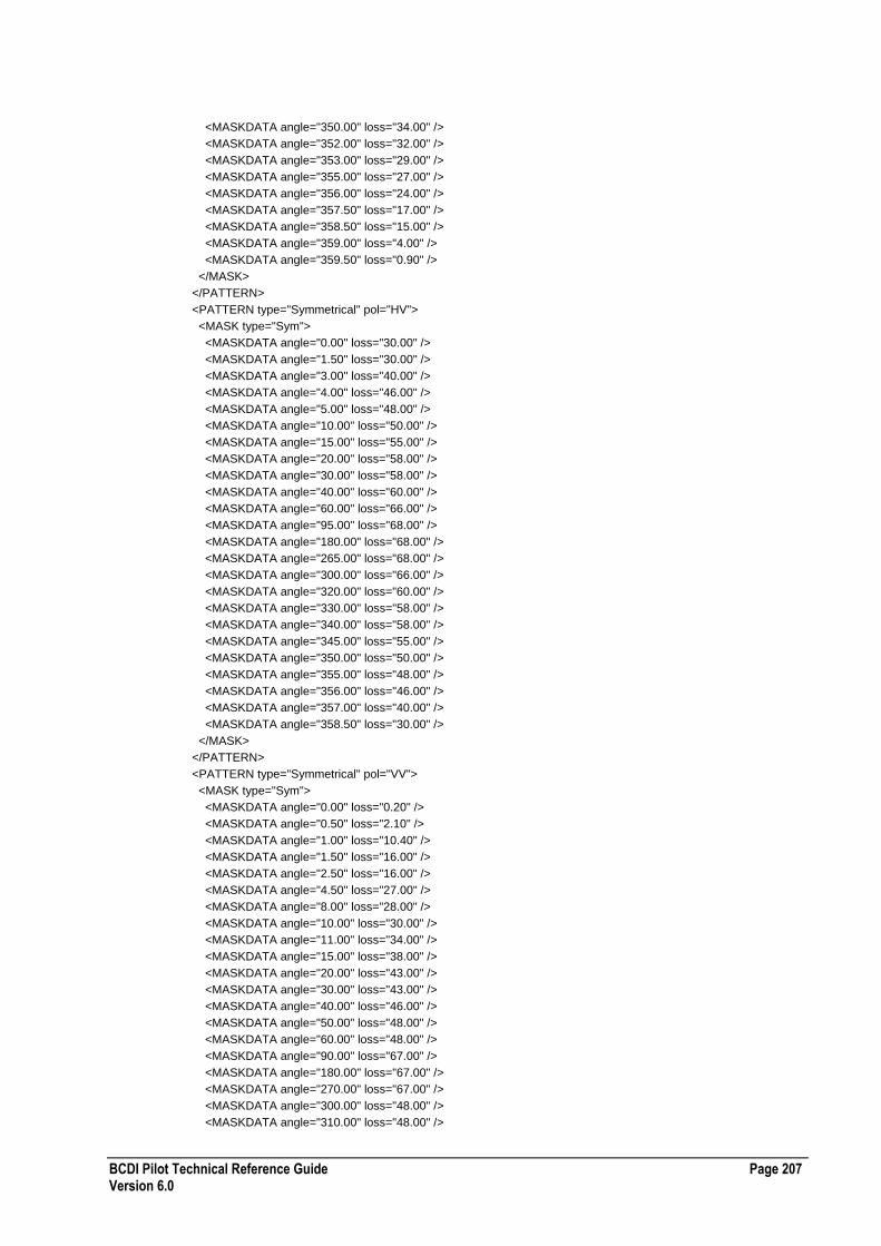
BCDI Pilot Technical Reference Guide Page 207 Version 6.0
<MASKDATA angle="350.00" loss="34.00" />
<MASKDATA angle="352.00" loss="32.00" />
<MASKDATA angle="353.00" loss="29.00" />
<MASKDATA angle="355.00" loss="27.00" />
<MASKDATA angle="356.00" loss="24.00" />
<MASKDATA angle="357.50" loss="17.00" />
<MASKDATA angle="358.50" loss="15.00" />
<MASKDATA angle="359.00" loss="4.00" />
<MASKDATA angle="359.50" loss="0.90" />
</MASK>
</PATTERN>
<PATTERN type="Symmetrical" pol="HV">
<MASK type="Sym">
<MASKDATA angle="0.00" loss="30.00" />
<MASKDATA angle="1.50" loss="30.00" />
<MASKDATA angle="3.00" loss="40.00" />
<MASKDATA angle="4.00" loss="46.00" />
<MASKDATA angle="5.00" loss="48.00" />
<MASKDATA angle="10.00" loss="50.00" />
<MASKDATA angle="15.00" loss="55.00" />
<MASKDATA angle="20.00" loss="58.00" />
<MASKDATA angle="30.00" loss="58.00" />
<MASKDATA angle="40.00" loss="60.00" />
<MASKDATA angle="60.00" loss="66.00" />
<MASKDATA angle="95.00" loss="68.00" />
<MASKDATA angle="180.00" loss="68.00" />
<MASKDATA angle="265.00" loss="68.00" />
<MASKDATA angle="300.00" loss="66.00" />
<MASKDATA angle="320.00" loss="60.00" />
<MASKDATA angle="330.00" loss="58.00" />
<MASKDATA angle="340.00" loss="58.00" />
<MASKDATA angle="345.00" loss="55.00" />
<MASKDATA angle="350.00" loss="50.00" />
<MASKDATA angle="355.00" loss="48.00" />
<MASKDATA angle="356.00" loss="46.00" />
<MASKDATA angle="357.00" loss="40.00" />
<MASKDATA angle="358.50" loss="30.00" />
</MASK>
</PATTERN>
<PATTERN type="Symmetrical" pol="VV">
<MASK type="Sym">
<MASKDATA angle="0.00" loss="0.20" />
<MASKDATA angle="0.50" loss="2.10" />
<MASKDATA angle="1.00" loss="10.40" />
<MASKDATA angle="1.50" loss="16.00" />
<MASKDATA angle="2.50" loss="16.00" />
<MASKDATA angle="4.50" loss="27.00" />
<MASKDATA angle="8.00" loss="28.00" />
<MASKDATA angle="10.00" loss="30.00" />
<MASKDATA angle="11.00" loss="34.00" />
<MASKDATA angle="15.00" loss="38.00" />
<MASKDATA angle="20.00" loss="43.00" />
<MASKDATA angle="30.00" loss="43.00" />
<MASKDATA angle="40.00" loss="46.00" />
<MASKDATA angle="50.00" loss="48.00" />
<MASKDATA angle="60.00" loss="48.00" />
<MASKDATA angle="90.00" loss="67.00" />
<MASKDATA angle="180.00" loss="67.00" />
<MASKDATA angle="270.00" loss="67.00" />
<MASKDATA angle="300.00" loss="48.00" />
<MASKDATA angle="310.00" loss="48.00" />
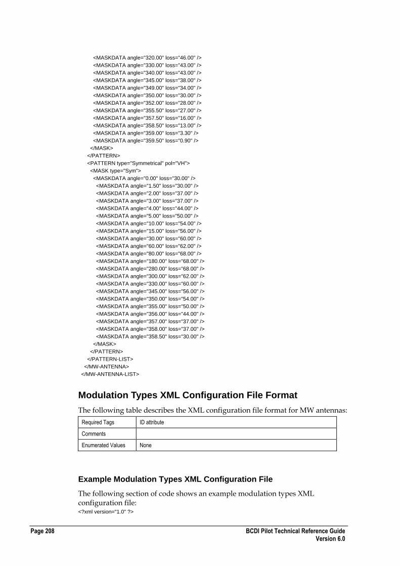
Page 208 BCDI Pilot Technical Reference Guide Version 6.0
<MASKDATA angle="320.00" loss="46.00" />
<MASKDATA angle="330.00" loss="43.00" />
<MASKDATA angle="340.00" loss="43.00" />
<MASKDATA angle="345.00" loss="38.00" />
<MASKDATA angle="349.00" loss="34.00" />
<MASKDATA angle="350.00" loss="30.00" />
<MASKDATA angle="352.00" loss="28.00" />
<MASKDATA angle="355.50" loss="27.00" />
<MASKDATA angle="357.50" loss="16.00" />
<MASKDATA angle="358.50" loss="13.00" />
<MASKDATA angle="359.00" loss="3.30" />
<MASKDATA angle="359.50" loss="0.90" />
</MASK>
</PATTERN>
<PATTERN type="Symmetrical" pol="VH">
<MASK type="Sym">
<MASKDATA angle="0.00" loss="30.00" />
<MASKDATA angle="1.50" loss="30.00" />
<MASKDATA angle="2.00" loss="37.00" />
<MASKDATA angle="3.00" loss="37.00" />
<MASKDATA angle="4.00" loss="44.00" />
<MASKDATA angle="5.00" loss="50.00" />
<MASKDATA angle="10.00" loss="54.00" />
<MASKDATA angle="15.00" loss="56.00" />
<MASKDATA angle="30.00" loss="60.00" />
<MASKDATA angle="60.00" loss="62.00" />
<MASKDATA angle="80.00" loss="68.00" />
<MASKDATA angle="180.00" loss="68.00" />
<MASKDATA angle="280.00" loss="68.00" />
<MASKDATA angle="300.00" loss="62.00" />
<MASKDATA angle="330.00" loss="60.00" />
<MASKDATA angle="345.00" loss="56.00" />
<MASKDATA angle="350.00" loss="54.00" />
<MASKDATA angle="355.00" loss="50.00" />
<MASKDATA angle="356.00" loss="44.00" />
<MASKDATA angle="357.00" loss="37.00" />
<MASKDATA angle="358.00" loss="37.00" />
<MASKDATA angle="358.50" loss="30.00" />
</MASK>
</PATTERN>
</PATTERN-LIST>
</MW-ANTENNA>
</MW-ANTENNA-LIST>
Modulation Types XML Configuration File Format
The following table describes the XML configuration file format for MW antennas:
Required Tags ID attribute
Comments
Enumerated Values None
Example Modulation Types XML Configuration File
The following section of code shows an example modulation types XML configuration file: <?xml version="1.0" ?>
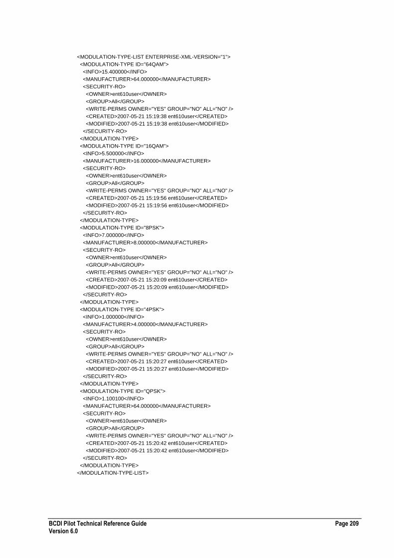
BCDI Pilot Technical Reference Guide Page 209 Version 6.0
<MODULATION-TYPE-LIST ENTERPRISE-XML-VERSION="1">
<MODULATION-TYPE ID="64QAM">
<INFO>15.400000</INFO>
<MANUFACTURER>64.000000</MANUFACTURER>
<SECURITY-RO>
<OWNER>ent610user</OWNER>
<GROUP>All</GROUP>
<WRITE-PERMS OWNER="YES" GROUP="NO" ALL="NO" />
<CREATED>2007-05-21 15:19:38 ent610user</CREATED>
<MODIFIED>2007-05-21 15:19:38 ent610user</MODIFIED>
</SECURITY-RO>
</MODULATION-TYPE>
<MODULATION-TYPE ID="16QAM">
<INFO>5.500000</INFO>
<MANUFACTURER>16.000000</MANUFACTURER>
<SECURITY-RO>
<OWNER>ent610user</OWNER>
<GROUP>All</GROUP>
<WRITE-PERMS OWNER="YES" GROUP="NO" ALL="NO" />
<CREATED>2007-05-21 15:19:56 ent610user</CREATED>
<MODIFIED>2007-05-21 15:19:56 ent610user</MODIFIED>
</SECURITY-RO>
</MODULATION-TYPE>
<MODULATION-TYPE ID="8PSK">
<INFO>7.000000</INFO>
<MANUFACTURER>8.000000</MANUFACTURER>
<SECURITY-RO>
<OWNER>ent610user</OWNER>
<GROUP>All</GROUP>
<WRITE-PERMS OWNER="YES" GROUP="NO" ALL="NO" />
<CREATED>2007-05-21 15:20:09 ent610user</CREATED>
<MODIFIED>2007-05-21 15:20:09 ent610user</MODIFIED>
</SECURITY-RO>
</MODULATION-TYPE>
<MODULATION-TYPE ID="4PSK">
<INFO>1.000000</INFO>
<MANUFACTURER>4.000000</MANUFACTURER>
<SECURITY-RO>
<OWNER>ent610user</OWNER>
<GROUP>All</GROUP>
<WRITE-PERMS OWNER="YES" GROUP="NO" ALL="NO" />
<CREATED>2007-05-21 15:20:27 ent610user</CREATED>
<MODIFIED>2007-05-21 15:20:27 ent610user</MODIFIED>
</SECURITY-RO>
</MODULATION-TYPE>
<MODULATION-TYPE ID="QPSK">
<INFO>1.100100</INFO>
<MANUFACTURER>64.000000</MANUFACTURER>
<SECURITY-RO>
<OWNER>ent610user</OWNER>
<GROUP>All</GROUP>
<WRITE-PERMS OWNER="YES" GROUP="NO" ALL="NO" />
<CREATED>2007-05-21 15:20:42 ent610user</CREATED>
<MODIFIED>2007-05-21 15:20:42 ent610user</MODIFIED>
</SECURITY-RO>
</MODULATION-TYPE>
</MODULATION-TYPE-LIST>

Page 210 BCDI Pilot Technical Reference Guide Version 6.0
Radio Equip XML Configuration File Format
The following table describes the XML configuration file format for radio equipment:
Required Tags ID attribute
Comments
Enumerated Values PROTECTED
[YES | NO]
TYPE
[PDH | SDH]
USE-XPIC
[YES | NO]
ATPC-CAPABLE
[YES | NO]
DUPLEXMETHOD
[FDD | TDD]
PDHSDH-VALUE
[E0 | E1 | E2 | E3 | E4 | E5 | T1 | T2 | T3 | T4 | J1 | J2 | J3 | J4 | J5 | STM1 | STM4 | STM16 | STM64 | STM265 | STS1 | STS3 | STS9 | STS12 | STS18 | STS36 | STS48 | STS192 | STS768]
MULTI-RADIO
[YES | NO]
USE-SIGNATURE-INFO
[YES | NO]
USE-APPROX-METHOD
[YES | NO]
USE-DISPERSIVE-FADE-MARGIN
[YES | NO]
USE-EQUALISER
[YES | NO]
USE-MSM
[YES | NO]
Example Radio Equip XML Configuration File
The following section of code shows an example radio equipment XML configuration file: <RADIO-LIST ENTERPRISE-XML-VERSION="1">
<RADIO ID=""FH26, 4x2"">
<INFO>
<MANUFACTURER>Nokia</MANUFACTURER>
<FAMILY>FlexiHopper</FAMILY>
<PROTECTED>no</PROTECTED>
<MIN-POWER>-7.000000</MIN-POWER>
<MAX-POWER>18.000000</MAX-POWER>

BCDI Pilot Technical Reference Guide Page 211 Version 6.0
<THRESHOLD1>-88.000000</THRESHOLD1>
<THRESHOLD2>-85.000000</THRESHOLD2>
<THRESHOLD1-BER>3</THRESHOLD1-BER>
<THRESHOLD2-BER>6</THRESHOLD2-BER>
<MTBF>30.000000</MTBF>
<NOISE-FIG>0.000000</NOISE-FIG>
<NOISE-TEMP>0.000000</NOISE-TEMP>
<FKTB>-100.000000</FKTB>
<TYPE>PDH</TYPE>
<USE-XPIC>no</USE-XPIC>
<XPIC-VALUE>0.000000</XPIC-VALUE>
<ATPCRANGE>0.000000</ATPCRANGE>
<ATPCCAPABLE>no</ATPCCAPABLE>
<TIOBJECT>13.000000</TIOBJECT>
</INFO>
<FREQUENCY>
<FREQUENCY-BAND>26000.000000</FREQUENCY-BAND>
<MINOPFREQ>24500.000000</MINOPFREQ>
<MAXOPFREQ>26500.000000</MAXOPFREQ>
<FREQBW>7.000000</FREQBW>
<MODULATION-TYPE>Undefined</MODULATION-TYPE>
<DUPLEXMETHOD>FDD</DUPLEXMETHOD>
<TRAFFIC-CHANNELS>0</TRAFFIC-CHANNELS>
<PDHSDH-VALUE>E1</PDHSDH-VALUE>
<CHANNELS>4</CHANNELS>
<SINGLEVALUE>0.000000</SINGLEVALUE>
</FREQUENCY>
<USAGE-MODE>
<RX-SINGLE>0.000000</RX-SINGLE>
<RX-HOT-STANDBY>3.000000</RX-HOT-STANDBY>
<RX-COLD-STANDBY>5.000000</RX-COLD-STANDBY>
<RX-1-PLUS-1>3.000000</RX-1-PLUS-1>
<RX-1-PLUS-1-2>6.000000</RX-1-PLUS-1-2>
<TX-SINGLE>0.000000</TX-SINGLE>
<TX-HOT-STANDBY>3.000000</TX-HOT-STANDBY>
<TX-COLD-STANDBY>3.000000</TX-COLD-STANDBY>
<TX-1-PLUS-1>3.000000</TX-1-PLUS-1>
<TX-1-PLUS-1-2>6.000000</TX-1-PLUS-1-2>
<RX-SDH-NM>0.000000</RX-SDH-NM>
<RX-SDH-NM>0.000000</RX-SDH-NM>
<RX-MOU-DUAL-NM>0.000000</RX-MOU-DUAL-NM>
<TX-MOU-DUAL-NM>0.000000</TX-MOU-DUAL-NM>
<MULTI-RADIO>NO</MULTI-RADIO>
</USAGE-MODE>
<SIGNATURE>
<MODULATION>QPSK</MODULATION>
<USE-SIGNATURE-INFO>yes</USE-SIGNATURE-INFO>
<USE-APPROX-METHOD>no</USE-APPROX-METHOD>
<USE-DISPERSIVE-FADE-MARGIN>no</USE-DISPERSIVE-FADE-MARGIN>
<WM>30.000000</WM>
<BM>30.000000</BM>
<TAUM>240.000000</TAUM>
<WNM>30.000000</WNM>
<BNM>30.000000</BNM>
<TAUNM>240.000000</TAUNM>
<USE-EQUALISER>no</USE-EQUALISER>
<KN-REDUCTION>1.000000</KN-REDUCTION>
<USE-MSM>no</USE-MSM>
<AD>1.000000</AD>
<MSM>1.000000</MSM>
<KN>1.000000</KN>
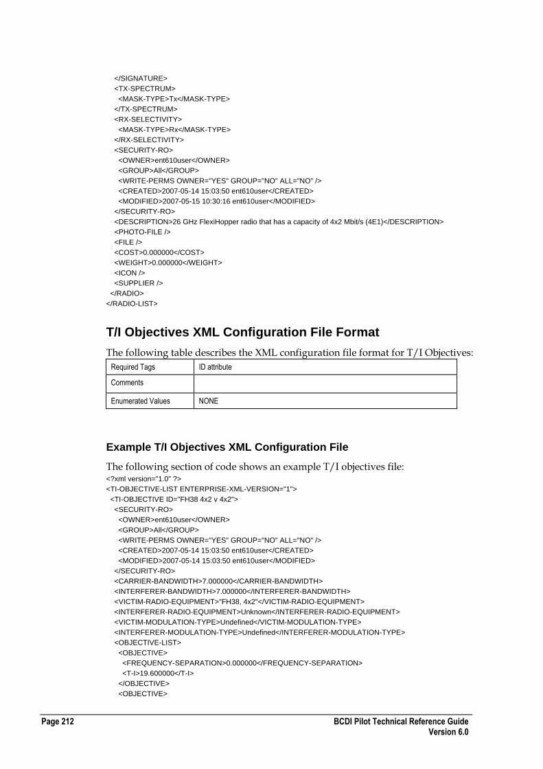
Page 212 BCDI Pilot Technical Reference Guide Version 6.0
</SIGNATURE>
<TX-SPECTRUM>
<MASK-TYPE>Tx</MASK-TYPE>
</TX-SPECTRUM>
<RX-SELECTIVITY>
<MASK-TYPE>Rx</MASK-TYPE>
</RX-SELECTIVITY>
<SECURITY-RO>
<OWNER>ent610user</OWNER>
<GROUP>All</GROUP>
<WRITE-PERMS OWNER="YES" GROUP="NO" ALL="NO" />
<CREATED>2007-05-14 15:03:50 ent610user</CREATED>
<MODIFIED>2007-05-15 10:30:16 ent610user</MODIFIED>
</SECURITY-RO>
<DESCRIPTION>26 GHz FlexiHopper radio that has a capacity of 4x2 Mbit/s (4E1)</DESCRIPTION>
<PHOTO-FILE />
<FILE />
<COST>0.000000</COST>
<WEIGHT>0.000000</WEIGHT>
<ICON />
<SUPPLIER />
</RADIO>
</RADIO-LIST>
T/I Objectives XML Configuration File Format
The following table describes the XML configuration file format for T/I Objectives:
Required Tags ID attribute
Comments
Enumerated Values NONE
Example T/I Objectives XML Configuration File
The following section of code shows an example T/I objectives file: <?xml version="1.0" ?>
<TI-OBJECTIVE-LIST ENTERPRISE-XML-VERSION="1">
<TI-OBJECTIVE ID="FH38 4x2 v 4x2">
<SECURITY-RO>
<OWNER>ent610user</OWNER>
<GROUP>All</GROUP>
<WRITE-PERMS OWNER="YES" GROUP="NO" ALL="NO" />
<CREATED>2007-05-14 15:03:50 ent610user</CREATED>
<MODIFIED>2007-05-14 15:03:50 ent610user</MODIFIED>
</SECURITY-RO>
<CARRIER-BANDWIDTH>7.000000</CARRIER-BANDWIDTH>
<INTERFERER-BANDWIDTH>7.000000</INTERFERER-BANDWIDTH>
<VICTIM-RADIO-EQUIPMENT>"FH38, 4x2"</VICTIM-RADIO-EQUIPMENT>
<INTERFERER-RADIO-EQUIPMENT>Unknown</INTERFERER-RADIO-EQUIPMENT>
<VICTIM-MODULATION-TYPE>Undefined</VICTIM-MODULATION-TYPE>
<INTERFERER-MODULATION-TYPE>Undefined</INTERFERER-MODULATION-TYPE>
<OBJECTIVE-LIST>
<OBJECTIVE>
<FREQUENCY-SEPARATION>0.000000</FREQUENCY-SEPARATION>
<T-I>19.600000</T-I>
</OBJECTIVE>
<OBJECTIVE>

BCDI Pilot Technical Reference Guide Page 213 Version 6.0
<FREQUENCY-SEPARATION>7.000000</FREQUENCY-SEPARATION>
<T-I>-10.000000</T-I>
</OBJECTIVE>
<OBJECTIVE>
<FREQUENCY-SEPARATION>14.000000</FREQUENCY-SEPARATION>
<T-I>-46.000000</T-I>
</OBJECTIVE>
<OBJECTIVE>
<FREQUENCY-SEPARATION>28.000000</FREQUENCY-SEPARATION>
<T-I>-49.400002</T-I>
</OBJECTIVE>
</OBJECTIVE-LIST>
</TI-OBJECTIVE>
<TI-OBJECTIVE ID="13/2E1/2E1">
<SECURITY-RO>
<OWNER>ent610user</OWNER>
<GROUP>All</GROUP>
<WRITE-PERMS OWNER="YES" GROUP="NO" ALL="NO" />
<CREATED>2007-05-14 15:03:50 ent610user</CREATED>
<MODIFIED>2007-05-14 15:03:50 ent610user</MODIFIED>
</SECURITY-RO>
<CARRIER-BANDWIDTH>3.500000</CARRIER-BANDWIDTH>
<INTERFERER-BANDWIDTH>3.500000</INTERFERER-BANDWIDTH>
<VICTIM-RADIO-EQUIPMENT>13GHz/ 2xE1</VICTIM-RADIO-EQUIPMENT>
<INTERFERER-RADIO-EQUIPMENT>Unknown</INTERFERER-RADIO-EQUIPMENT>
<VICTIM-MODULATION-TYPE>Undefined</VICTIM-MODULATION-TYPE>
<INTERFERER-MODULATION-TYPE>Undefined</INTERFERER-MODULATION-TYPE>
<OBJECTIVE-LIST>
<OBJECTIVE>
<FREQUENCY-SEPARATION>0.000000</FREQUENCY-SEPARATION>
<T-I>15.000000</T-I>
</OBJECTIVE>
<OBJECTIVE>
<FREQUENCY-SEPARATION>3.500000</FREQUENCY-SEPARATION>
<T-I>14.000000</T-I>
</OBJECTIVE>
<OBJECTIVE>
<FREQUENCY-SEPARATION>7.000000</FREQUENCY-SEPARATION>
<T-I>8.000000</T-I>
</OBJECTIVE>
<OBJECTIVE>
<FREQUENCY-SEPARATION>10.500000</FREQUENCY-SEPARATION>
<T-I>-2.000000</T-I>
</OBJECTIVE>
<OBJECTIVE>
<FREQUENCY-SEPARATION>14.000000</FREQUENCY-SEPARATION>
<T-I>-2.000000</T-I>
</OBJECTIVE>
<OBJECTIVE>
<FREQUENCY-SEPARATION>17.500000</FREQUENCY-SEPARATION>
<T-I>-2.000000</T-I>
</OBJECTIVE>
<OBJECTIVE>
<FREQUENCY-SEPARATION>21.000000</FREQUENCY-SEPARATION>
<T-I>-3.000000</T-I>
</OBJECTIVE>
<OBJECTIVE>
<FREQUENCY-SEPARATION>24.500000</FREQUENCY-SEPARATION>
<T-I>-4.000000</T-I>
</OBJECTIVE>
<OBJECTIVE>

Page 214 BCDI Pilot Technical Reference Guide Version 6.0
<FREQUENCY-SEPARATION>28.000000</FREQUENCY-SEPARATION>
<T-I>-9.000000</T-I>
</OBJECTIVE>
<OBJECTIVE>
<FREQUENCY-SEPARATION>35.000000</FREQUENCY-SEPARATION>
<T-I>-18.000000</T-I>
</OBJECTIVE>
<OBJECTIVE>
<FREQUENCY-SEPARATION>42.000000</FREQUENCY-SEPARATION>
<T-I>-30.000000</T-I>
</OBJECTIVE>
<OBJECTIVE>
<FREQUENCY-SEPARATION>84.000000</FREQUENCY-SEPARATION>
<T-I>-30.000000</T-I>
</OBJECTIVE>
</OBJECTIVE-LIST>
</TI-OBJECTIVE>
<TI-OBJECTIVE ID="13/2E1/4E1">
<SECURITY-RO>
<OWNER>ent610user</OWNER>
<GROUP>All</GROUP>
<WRITE-PERMS OWNER="YES" GROUP="NO" ALL="NO" />
<CREATED>2007-05-14 15:03:50 ent610user</CREATED>
<MODIFIED>2007-05-14 15:03:50 ent610user</MODIFIED>
</SECURITY-RO>
<CARRIER-BANDWIDTH>3.500000</CARRIER-BANDWIDTH>
<INTERFERER-BANDWIDTH>7.000000</INTERFERER-BANDWIDTH>
<VICTIM-RADIO-EQUIPMENT>13GHz/ 2xE1</VICTIM-RADIO-EQUIPMENT>
<INTERFERER-RADIO-EQUIPMENT>Unknown</INTERFERER-RADIO-EQUIPMENT>
<VICTIM-MODULATION-TYPE>Undefined</VICTIM-MODULATION-TYPE>
<INTERFERER-MODULATION-TYPE>Undefined</INTERFERER-MODULATION-TYPE>
<OBJECTIVE-LIST>
<OBJECTIVE>
<FREQUENCY-SEPARATION>0.000000</FREQUENCY-SEPARATION>
<T-I>15.000000</T-I>
</OBJECTIVE>
<OBJECTIVE>
<FREQUENCY-SEPARATION>3.500000</FREQUENCY-SEPARATION>
<T-I>14.000000</T-I>
</OBJECTIVE>
<OBJECTIVE>
<FREQUENCY-SEPARATION>7.000000</FREQUENCY-SEPARATION>
<T-I>8.000000</T-I>
</OBJECTIVE>
<OBJECTIVE>
<FREQUENCY-SEPARATION>10.500000</FREQUENCY-SEPARATION>
<T-I>-2.000000</T-I>
</OBJECTIVE>
<OBJECTIVE>
<FREQUENCY-SEPARATION>14.000000</FREQUENCY-SEPARATION>
<T-I>-2.000000</T-I>
</OBJECTIVE>
<OBJECTIVE>
<FREQUENCY-SEPARATION>17.500000</FREQUENCY-SEPARATION>
<T-I>-2.000000</T-I>
</OBJECTIVE>
<OBJECTIVE>
<FREQUENCY-SEPARATION>21.000000</FREQUENCY-SEPARATION>
<T-I>-3.000000</T-I>
</OBJECTIVE>
<OBJECTIVE>

BCDI Pilot Technical Reference Guide Page 215 Version 6.0
<FREQUENCY-SEPARATION>24.500000</FREQUENCY-SEPARATION>
<T-I>-4.000000</T-I>
</OBJECTIVE>
<OBJECTIVE>
<FREQUENCY-SEPARATION>28.000000</FREQUENCY-SEPARATION>
<T-I>-9.000000</T-I>
</OBJECTIVE>
<OBJECTIVE>
<FREQUENCY-SEPARATION>35.000000</FREQUENCY-SEPARATION>
<T-I>-18.000000</T-I>
</OBJECTIVE>
<OBJECTIVE>
<FREQUENCY-SEPARATION>42.000000</FREQUENCY-SEPARATION>
<T-I>-30.000000</T-I>
</OBJECTIVE>
<OBJECTIVE>
<FREQUENCY-SEPARATION>84.000000</FREQUENCY-SEPARATION>
<T-I>-30.000000</T-I>
</OBJECTIVE>
</OBJECTIVE-LIST>
</TI-OBJECTIVE>
Bearers XML Configuration File Format
The following table describes the XML configuration file format for bearers:
Required Tags ID attribute
TECH attribute
LINK-DIRECTION
Comments Each of the sample bearers below belongs to a different technology type. The xml exporter will only generate the necessary elements that applied to the technology type or the link direction.
0 or more <BEARER> elements can exist. The attribute TECH value must be one of the enumerated values otherwise the bearer will failed to import.
Some elements only applies to the selected link direction. Those are identified by a comment in the sample below.
If a service failed to be imported, a message giving the cause of the failure can be found in the message log.

Page 216 BCDI Pilot Technical Reference Guide Version 6.0
Enumerated Values TECH
[UMTS | CMDA2000 | EV-DO | WIMAX-MOBILE]
LINK-DIRECTION
[UPLINK | DOWNLINK]
RC-UL
[RC1 | RC2 | RC3 | RC4 | RC5 | RC6]
RC-DL
[RC1 | RC2 | RC3 | RC4 | RC5 | RC6 | RC7 | RC8 | RC9 | RC10]
RC-CODING-TYPE
[Convolutional | Turbo]
RC-FRAME-LENGTH
[5 | 20 | 40 | 80]
SPEED ID
[3KMH | 50KMH | 120KMH | 2MPH | 31MPH | 75MPH]
MAP EBNO
[-4 | -2 | 0 | 2 | 4 | 6 | 8 | 10]
BANDWIDTH
[1.25 | 3.5 | 5 | 7 | 8.75 | 10 | 14 | 20]
SUBCHAN-ALLOC-MODE
[PUSC | FUSC]
MODULATION
[QPSK | 8QAM | 16QAM]
REPETITION
[1 | 2 | 4 | 6]
DL-MIMO-MODE
[Not Supported | Spatial Diversity | Spatial Multiplexing | Both]
Example Bearers XML Configuration File
The following section of code shows an example bearers XML configuration file: <?xml version="1.0" ?>
<BEARERS-LIST ENTERPRISE-XML-VERSION="2">
<BEARER ID="GPRS" TECH="GPRS">
<SECURITY-RO>
<OWNER>ent5123user</OWNER>
<GROUP>All</GROUP>
<WRITE-PERMS OWNER="YES" GROUP="NO" ALL="NO" />
<CREATED>2005-11-24 00:55:36 ent5123user</CREATED>
<MODIFIED>2005-11-24 00:55:36 ent5123user</MODIFIED>
</SECURITY-RO>
<LINK-DIRECTION>DOWNLINK</LINK-DIRECTION>
<MIN-FULLRATE-DB>7.000000</MIN-FULLRATE-DB>
<USER-BITRATE>12000</USER-BITRATE>
<SUPPORT-HALFRATE>NO</SUPPORT-HALFRATE>
<MIN-HALFRATE-DB>11.000000</MIN-HALFRATE-DB>
<SUPPORT-AMR>NO</SUPPORT-AMR>
<MIN-AMR-FULLRATE-DB>7.000000</MIN-AMR-FULLRATE-DB>

BCDI Pilot Technical Reference Guide Page 217 Version 6.0
<MIN-AMR-HALFRATE-DB>10.000000</MIN-AMR-HALFRATE-DB>
</BEARER>
<BEARER ID="UL UMTS Voice" TECH="UMTS">
<SECURITY-RO>
<OWNER>ent5123user</OWNER>
<GROUP>All</GROUP>
<WRITE-PERMS OWNER="YES" GROUP="NO" ALL="NO" />
<CREATED>2005-11-24 00:59:20 ent5123user</CREATED>
<MODIFIED>2005-11-24 00:59:20 ent5123user</MODIFIED>
</SECURITY-RO>
<LINK-DIRECTION>UPLINK</LINK-DIRECTION>
<AIR-INTERFACE-BITRATE>12200</AIR-INTERFACE-BITRATE>
<USER-BITRATE>12200</USER-BITRATE>
<CTRL-OVERHEAD>0.000000</CTRL-OVERHEAD>
<RC-LIST>
<RESOURCE ID="Channels - NodeB." VALUE="0" />
<RESOURCE ID="X - Carrier" VALUE="0" />
<RESOURCE ID="Y - Cell" VALUE="0" />
<RESOURCE ID="Z - Air interface" VALUE="0" />
<RESOURCE ID="Type4" VALUE="0" />
<RESOURCE ID="Type5" VALUE="0" />
</RC-LIST>
<NOISE-MODEL-MAP-LIST>
<MAP EBNO="-4" BER="0.4" />
<MAP EBNO="-2" BER="0.2" />
<MAP EBNO="0" BER="0.1" />
<MAP EBNO="2" BER="0.055" />
<MAP EBNO="4" BER="0.01" />
<MAP EBNO="6" BER="0.00325" />
<MAP EBNO="8" BER="0.0001" />
<MAP EBNO="10" BER="1e-006" />
<MAP EBNO="12" BER="1e-009" />
<MAP EBNO="14" BER="1e-012" />
</NOISE-MODEL-MAP-LIST>
<EBNO-VALUES>
<EBNO WITHOUT-DIVERSITY="6" WITH-DIVERSITY="6" />
<EBNO-DELTA-LIST>
<SPEED ID="3KMH" WITHOUT-DIVERSITY="0" WITH-DIVERSITY="0" />
<SPEED ID="50KMH" WITHOUT-DIVERSITY="0" WITH-DIVERSITY="0" />
<SPEED ID="120KMH" WITHOUT-DIVERSITY="0" WITH-DIVERSITY="0" />
</EBNO-DELTA-LIST>
</EBNO-VALUES>
<POWER-CONTROL-LIST>
<SPEED ID="3KMH" POWER-CTR-HEADROOM="0" AVG-PWR-RISE="0" />
<SPEED ID="50KMH" POWER-CTR-HEADROOM="0" AVG-PWR-RISE="0" />
<SPEED ID="120KMH" POWER-CTR-HEADROOM="0" AVG-PWR-RISE="0" />
</POWER-CONTROL-LIST>
<UL-POWER-GAINS>
<SOFT>
<TXP-GAIN-LIST>
<SPEED ID="3KMH" EBNO-0DB="0" EBNO-3DB="0" EBNO-6DB="0" EBNO-10DB="0" />
<SPEED ID="50KMH" EBNO-0DB="0" EBNO-3DB="0" EBNO-6DB="0" EBNO-10DB="0" />
<SPEED ID="120KMH" EBNO-0DB="0" EBNO-3DB="0" EBNO-6DB="0" EBNO-10DB="0" />
</TXP-GAIN-LIST>
<PR-GAIN-LIST>
<SPEED ID="3KMH" EBNO-0DB="0" EBNO-3DB="0" EBNO-6DB="0" EBNO-10DB="0" />
<SPEED ID="50KMH" EBNO-0DB="0" EBNO-3DB="0" EBNO-6DB="0" EBNO-10DB="0" />
<SPEED ID="120KMH" EBNO-0DB="0" EBNO-3DB="0" EBNO-6DB="0" EBNO-10DB="0" />
</PR-GAIN-LIST>
<PCH-GAIN-LIST>
<SPEED ID="3KMH" EBNO-0DB="0" EBNO-3DB="0" EBNO-6DB="0" EBNO-10DB="0" />
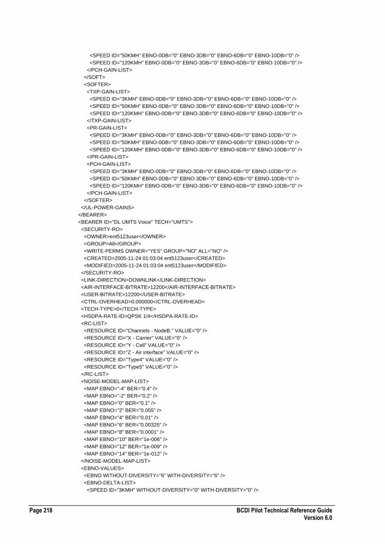
Page 218 BCDI Pilot Technical Reference Guide Version 6.0
<SPEED ID="50KMH" EBNO-0DB="0" EBNO-3DB="0" EBNO-6DB="0" EBNO-10DB="0" />
<SPEED ID="120KMH" EBNO-0DB="0" EBNO-3DB="0" EBNO-6DB="0" EBNO-10DB="0" />
</PCH-GAIN-LIST>
</SOFT>
<SOFTER>
<TXP-GAIN-LIST>
<SPEED ID="3KMH" EBNO-0DB="0" EBNO-3DB="0" EBNO-6DB="0" EBNO-10DB="0" />
<SPEED ID="50KMH" EBNO-0DB="0" EBNO-3DB="0" EBNO-6DB="0" EBNO-10DB="0" />
<SPEED ID="120KMH" EBNO-0DB="0" EBNO-3DB="0" EBNO-6DB="0" EBNO-10DB="0" />
</TXP-GAIN-LIST>
<PR-GAIN-LIST>
<SPEED ID="3KMH" EBNO-0DB="0" EBNO-3DB="0" EBNO-6DB="0" EBNO-10DB="0" />
<SPEED ID="50KMH" EBNO-0DB="0" EBNO-3DB="0" EBNO-6DB="0" EBNO-10DB="0" />
<SPEED ID="120KMH" EBNO-0DB="0" EBNO-3DB="0" EBNO-6DB="0" EBNO-10DB="0" />
</PR-GAIN-LIST>
<PCH-GAIN-LIST>
<SPEED ID="3KMH" EBNO-0DB="0" EBNO-3DB="0" EBNO-6DB="0" EBNO-10DB="0" />
<SPEED ID="50KMH" EBNO-0DB="0" EBNO-3DB="0" EBNO-6DB="0" EBNO-10DB="0" />
<SPEED ID="120KMH" EBNO-0DB="0" EBNO-3DB="0" EBNO-6DB="0" EBNO-10DB="0" />
</PCH-GAIN-LIST>
</SOFTER>
</UL-POWER-GAINS>
</BEARER>
<BEARER ID="DL UMTS Voice" TECH="UMTS">
<SECURITY-RO>
<OWNER>ent5123user</OWNER>
<GROUP>All</GROUP>
<WRITE-PERMS OWNER="YES" GROUP="NO" ALL="NO" />
<CREATED>2005-11-24 01:03:04 ent5123user</CREATED>
<MODIFIED>2005-11-24 01:03:04 ent5123user</MODIFIED>
</SECURITY-RO>
<LINK-DIRECTION>DOWNLINK</LINK-DIRECTION>
<AIR-INTERFACE-BITRATE>12200</AIR-INTERFACE-BITRATE>
<USER-BITRATE>12200</USER-BITRATE>
<CTRL-OVERHEAD>0.000000</CTRL-OVERHEAD>
<TECH-TYPE>0</TECH-TYPE>
<HSDPA-RATE-ID>QPSK 1/4</HSDPA-RATE-ID>
<RC-LIST>
<RESOURCE ID="Channels - NodeB." VALUE="0" />
<RESOURCE ID="X - Carrier" VALUE="0" />
<RESOURCE ID="Y - Cell" VALUE="0" />
<RESOURCE ID="Z - Air interface" VALUE="0" />
<RESOURCE ID="Type4" VALUE="0" />
<RESOURCE ID="Type5" VALUE="0" />
</RC-LIST>
<NOISE-MODEL-MAP-LIST>
<MAP EBNO="-4" BER="0.4" />
<MAP EBNO="-2" BER="0.2" />
<MAP EBNO="0" BER="0.1" />
<MAP EBNO="2" BER="0.055" />
<MAP EBNO="4" BER="0.01" />
<MAP EBNO="6" BER="0.00325" />
<MAP EBNO="8" BER="0.0001" />
<MAP EBNO="10" BER="1e-006" />
<MAP EBNO="12" BER="1e-009" />
<MAP EBNO="14" BER="1e-012" />
</NOISE-MODEL-MAP-LIST>
<EBNO-VALUES>
<EBNO WITHOUT-DIVERSITY="6" WITH-DIVERSITY="6" />
<EBNO-DELTA-LIST>
<SPEED ID="3KMH" WITHOUT-DIVERSITY="0" WITH-DIVERSITY="0" />

BCDI Pilot Technical Reference Guide Page 219 Version 6.0
<SPEED ID="50KMH" WITHOUT-DIVERSITY="0" WITH-DIVERSITY="0" />
<SPEED ID="120KMH" WITHOUT-DIVERSITY="0" WITH-DIVERSITY="0" />
</EBNO-DELTA-LIST>
</EBNO-VALUES>
<DL-POWER-GAINS>
<MAX-TX-POWER>30.000000</MAX-TX-POWER>
<DOWNLINK-GAIN-LIST>
<SPEED ID="3KMH" EBNO-0DB="0" EBNO-3DB="0" EBNO-6DB="0" EBNO-10DB="0" />
<SPEED ID="50KMH" EBNO-0DB="0" EBNO-3DB="0" EBNO-6DB="0" EBNO-10DB="0" />
<SPEED ID="120KMH" EBNO-0DB="0" EBNO-3DB="0" EBNO-6DB="0" EBNO-10DB="0" />
</DOWNLINK-GAIN-LIST>
</DL-POWER-GAINS>
</BEARER>
<BEARER ID="GSM Voice" TECH="GSMVOICE">
<SECURITY-RO>
<OWNER>ent5123user</OWNER>
<GROUP>All</GROUP>
<WRITE-PERMS OWNER="YES" GROUP="NO" ALL="NO" />
<CREATED>2005-11-24 01:06:48 ent5123user</CREATED>
<MODIFIED>2005-11-24 01:06:48 ent5123user</MODIFIED>
</SECURITY-RO>
<LINK-DIRECTION>DOWNLINK</LINK-DIRECTION>
<MIN-FULLRATE-DB>7.000000</MIN-FULLRATE-DB>
<USER-BITRATE>12000</USER-BITRATE>
<SUPPORT-HALFRATE>NO</SUPPORT-HALFRATE>
<MIN-HALFRATE-DB>11.000000</MIN-HALFRATE-DB>
<SUPPORT-AMR>NO</SUPPORT-AMR>
<MIN-AMR-FULLRATE-DB>7.000000</MIN-AMR-FULLRATE-DB>
<MIN-AMR-HALFRATE-DB>10.000000</MIN-AMR-HALFRATE-DB>
</BEARER>
<BEARER ID="Bearer1" TECH="WiMAX-MOBILE">
<SECURITY-RO>
<OWNER>ent6016user</OWNER>
<GROUP>All</GROUP>
<CREATED>2007-06-06 15:03:34 ent6016user</CREATED>
<MODIFIED>2007-06-06 15:03:34 ent6016user</MODIFIED>
</SECURITY-RO>
<LINK-DIRECTION>DOWNLINK</LINK-DIRECTION>
<BANDWIDTH>5.000000</BANDWIDTH>
<SUBCHAN-ALLOC-MODE>PUSC</SUBCHAN-ALLOC-MODE>
<MODULATION>QPSK</MODULATION>
<CODING-RATE>0.33</CODING-RATE>
<REPETITION>1</REPETITION>
<CINR>6.000</CINR>
<CINR-SPEED-DEP-0TO3>0.000</CINR-SPEED-DEP-0TO3>
<CINR-SPEED-DEP-50>0.000</CINR-SPEED-DEP-50>
<CINR-SPEED-DEP-TO120>0.000</CINR-SPEED-DEP-TO120>
<TX-PWR-BACK-OFF>0.00</TX-PWR-BACK-OFF>
<DL-MIMO-MODE>Both</DL-MIMO-MODE>
</BEARER>
</BEARERS-LIST>
Services XML Configuration File Format
The following table describes the XML configuration file format for services:
Required Tags ID attribute
TECH attribute

Page 220 BCDI Pilot Technical Reference Guide Version 6.0
Comments Each of the sample services below belongs to a different technology type. The xml exporter will only generate the necessary elements that applied to the technology type or the traffic characteristics.
0 or more <SERVICE> elements can exist. The attribute TECH value must be one of the enumerated values otherwise the service will failed to import.
<CARRIER-PRIORITIES> element list is the supported carriers list, ordered by priority. The ID attribute of element <CARRIER> must matched to the pre-defined carriers 1..32 in the project.
<UL-BEARER-PRIORITIES> element list is the supported carriers list. Each supported carrier can have a list of supported bearers, ordered by priority. The bearer attribute ID value must exist already or have been imported otherwise the bearer will not be assigned to the carrier on import. The same applied to element <DL-BEARER-PRIORITIES>.
Some elements only apply to the selected traffic type. Those are identified by a comment in the sample below.
If a service failed to be imported, a message giving the cause of the failure can be found in the message log.
Enumerated Values TECH
[UMTS | CMDA2000 | EV-DO | GSM | WIMAX MOBILE]
TRAFFIC-TYPE
[VOICE | RT | NRT]
USE-SOFT-HO
USE-SUPPL-CHAN-HO
IGNORE-PRIORITY
[YES | NO]
RECEDENCE-CLASS
[Standard | Premium | Best Effort]
TRAF-CLASS
[Conversational Audio | Conversational Data | Streaming Audio | Streaming Video | Streaming Data | Interactive Audio | Interactive Data Background]
Example Services XML Configuration File
The following section of code shows an example services XML configuration file: <?xml version="1.0" ?>
<SERVICES-LIST ENTERPRISE-XML-VERSION="4">
<SERVICE ID="TDD Service" TECH="UMTS-TDD" OVERRIDE-ACTIVITY="0">
<SECURITY-RO>
<OWNER>ent5123user</OWNER>
<GROUP>All</GROUP>
<WRITE-PERMS OWNER="YES" GROUP="NO" ALL="NO" />
<CREATED>2005-11-23 11:58:49 ent5123user</CREATED>
<MODIFIED>2005-11-24 01:36:40 ent5123user</MODIFIED>
</SECURITY-RO>
<CARRIER-PRIORITY-LIST>
<CARRIER ID="1" TECH="UMTS-TDD" />
</CARRIER-PRIORITY-LIST>
<DL-BEARER-PRIORITIES>
<CARRIER ID="1" />
</DL-BEARER-PRIORITIES>
</SERVICE>
<SERVICE ID="UMTS Voice" TECH="UMTS" OVERRIDE-ACTIVITY="0">

BCDI Pilot Technical Reference Guide Page 221 Version 6.0
<SECURITY-RO>
<OWNER>ent5123user</OWNER>
<GROUP>All</GROUP>
<WRITE-PERMS OWNER="YES" GROUP="NO" ALL="NO" />
<CREATED>2005-11-23 11:58:49 ent5123user</CREATED>
<MODIFIED>2005-11-24 01:44:08 ent5123user</MODIFIED>
</SECURITY-RO>
<TRAFFIC-TYPE>VOICE</TRAFFIC-TYPE>
<CS-ACTIVITY-UL>50.000000</CS-ACTIVITY-UL>
<CS-ACTIVITY-DL>50.000000</CS-ACTIVITY-DL>
<USE-SOFT-HO>YES</USE-SOFT-HO>
<CARRIER-PRIORITY-LIST>
<CARRIER ID="1" TECH="UMTS" />
</CARRIER-PRIORITY-LIST>
<IGNORE-PRIORITY>NO</IGNORE-PRIORITY>
<UL-BEARER-PRIORITIES>
<CARRIER ID="1" />
</UL-BEARER-PRIORITIES>
<DL-BEARER-PRIORITIES>
<CARRIER ID="1" />
</DL-BEARER-PRIORITIES>
</SERVICE>
<SERVICE ID="GSM Voice" TECH="UMTS" OVERRIDE-ACTIVITY="0">
<SECURITY-RO>
<OWNER>ent5123user</OWNER>
<GROUP>All</GROUP>
<WRITE-PERMS OWNER="YES" GROUP="NO" ALL="NO" />
<CREATED>2005-11-23 11:58:49 ent5123user</CREATED>
<MODIFIED>2005-11-24 01:51:36 ent5123user</MODIFIED>
</SECURITY-RO>
<TRAFFIC-TYPE>VOICE</TRAFFIC-TYPE>
<CS-ACTIVITY-UL>50.000000</CS-ACTIVITY-UL>
<CS-ACTIVITY-DL>50.000000</CS-ACTIVITY-DL>
<USE-SOFT-HO>NO</USE-SOFT-HO>
<CARRIER-PRIORITY-LIST>
<CARRIER ID="GSM-900" TECH="GSM" />
</CARRIER-PRIORITY-LIST>
<IGNORE-PRIORITY>NO</IGNORE-PRIORITY>
<UL-BEARER-PRIORITIES />
<DL-BEARER-PRIORITIES>
<CARRIER ID="GSM-900" />
</DL-BEARER-PRIORITIES>
</SERVICE>
<SERVICE ID="Service4" TECH="WiMAX-MOBILE" OVERRIDE-ACTIVITY="0">
<SECURITY-RO>
<OWNER>ent6016user</OWNER>
<GROUP>All</GROUP>
<CREATED>2007-06-06 16:00:09 ent6016user</CREATED>
<MODIFIED>2007-06-06 16:00:27 ent6016user</MODIFIED>
</SECURITY-RO>
<CARRIER-PRIORITY-LIST>
<CARRIER ID="2" TECH="WiMAX-MOBILE" />
<CARRIER ID="3" TECH="WiMAX-MOBILE" />
</CARRIER-PRIORITY-LIST>
<UL-SERVICE-RATE>12200.000</UL-SERVICE-RATE>
<UL-BEARER-PRIORITIES>
<CARRIER ID="2" />
<CARRIER ID="3" />
</UL-BEARER-PRIORITIES>
<DL-SERVICE-RATE>12200.000</DL-SERVICE-RATE>
<DL-BEARER-PRIORITIES>

Page 222 BCDI Pilot Technical Reference Guide Version 6.0
<CARRIER ID="2" />
<CARRIER ID="3" />
</DL-BEARER-PRIORITIES>
</SERVICE>
</SERVICES-LIST>
EV-DO DL Parameters XML Configuration File Format
The following table describes the XML configuration file format for EV-DO downlink parameters:
Required Tags BITRATE attribute
SLOTS attribute
Comments 0 or more <EV-DO-DL-PARAMETERS> elements can exist.
The attributes BITRATE and SLOTS value must came from the same row from the table below otherwise the EV-DO Parameter will failed to import. Like wise, the <NUMBER-BITS>, <OVERHEAD-BITS> and <CHIPS-TRAFFIC-BITS> must came from the same corresponding row.
If an EV-DO Parameter failed to be imported, a message giving the cause of the failure can be found in the message log.
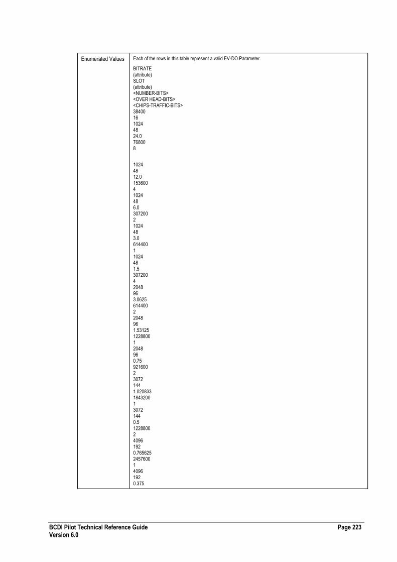
BCDI Pilot Technical Reference Guide Page 223 Version 6.0
Enumerated Values Each of the rows in this table represent a valid EV-DO Parameter.
BITRATE (attribute) SLOT (attribute) <NUMBER-BITS> <OVER HEAD-BITS> <CHIPS-TRAFFIC-BITS> 38400 16 1024 48 24.0 76800 8
1024 48 12.0 153600 4 1024 48 6.0 307200 2 1024 48 3.0 614400 1 1024 48 1.5 307200 4 2048 96 3.0625 614400 2 2048 96 1.53125 1228800 1 2048 96 0.75 921600 2 3072 144 1.020833 1843200 1 3072 144 0.5 1228800 2 4096 192 0.765625 2457600 1 4096 192 0.375
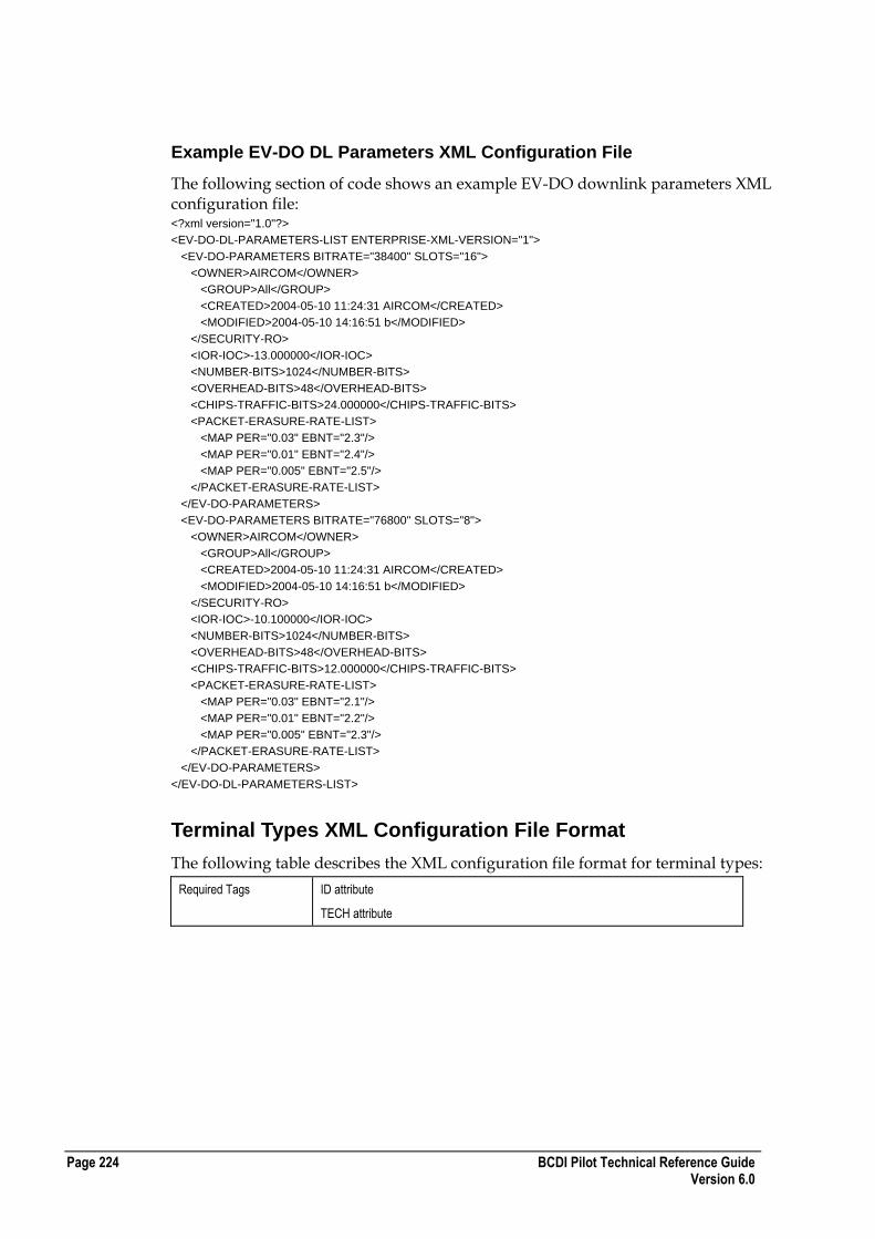
Page 224 BCDI Pilot Technical Reference Guide Version 6.0
Example EV-DO DL Parameters XML Configuration File
The following section of code shows an example EV-DO downlink parameters XML configuration file: <?xml version="1.0"?>
<EV-DO-DL-PARAMETERS-LIST ENTERPRISE-XML-VERSION="1">
<EV-DO-PARAMETERS BITRATE="38400" SLOTS="16">
<OWNER>AIRCOM</OWNER>
<GROUP>All</GROUP>
<CREATED>2004-05-10 11:24:31 AIRCOM</CREATED>
<MODIFIED>2004-05-10 14:16:51 b</MODIFIED>
</SECURITY-RO>
<IOR-IOC>-13.000000</IOR-IOC>
<NUMBER-BITS>1024</NUMBER-BITS>
<OVERHEAD-BITS>48</OVERHEAD-BITS>
<CHIPS-TRAFFIC-BITS>24.000000</CHIPS-TRAFFIC-BITS>
<PACKET-ERASURE-RATE-LIST>
<MAP PER="0.03" EBNT="2.3"/>
<MAP PER="0.01" EBNT="2.4"/>
<MAP PER="0.005" EBNT="2.5"/>
</PACKET-ERASURE-RATE-LIST>
</EV-DO-PARAMETERS>
<EV-DO-PARAMETERS BITRATE="76800" SLOTS="8">
<OWNER>AIRCOM</OWNER>
<GROUP>All</GROUP>
<CREATED>2004-05-10 11:24:31 AIRCOM</CREATED>
<MODIFIED>2004-05-10 14:16:51 b</MODIFIED>
</SECURITY-RO>
<IOR-IOC>-10.100000</IOR-IOC>
<NUMBER-BITS>1024</NUMBER-BITS>
<OVERHEAD-BITS>48</OVERHEAD-BITS>
<CHIPS-TRAFFIC-BITS>12.000000</CHIPS-TRAFFIC-BITS>
<PACKET-ERASURE-RATE-LIST>
<MAP PER="0.03" EBNT="2.1"/>
<MAP PER="0.01" EBNT="2.2"/>
<MAP PER="0.005" EBNT="2.3"/>
</PACKET-ERASURE-RATE-LIST>
</EV-DO-PARAMETERS>
</EV-DO-DL-PARAMETERS-LIST>
Terminal Types XML Configuration File Format
The following table describes the XML configuration file format for terminal types:
Required Tags ID attribute
TECH attribute
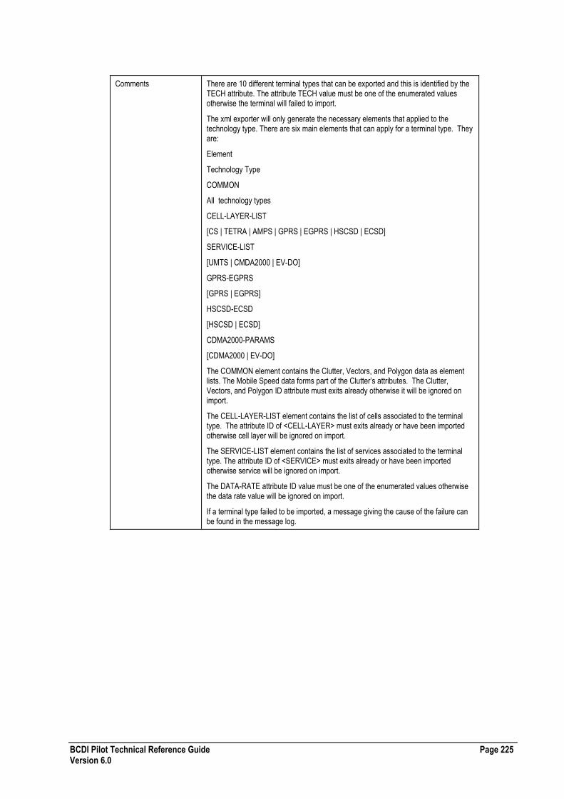
BCDI Pilot Technical Reference Guide Page 225 Version 6.0
Comments There are 10 different terminal types that can be exported and this is identified by the TECH attribute. The attribute TECH value must be one of the enumerated values otherwise the terminal will failed to import.
The xml exporter will only generate the necessary elements that applied to the technology type. There are six main elements that can apply for a terminal type. They are:
Element
Technology Type
COMMON
All technology types
CELL-LAYER-LIST
[CS | TETRA | AMPS | GPRS | EGPRS | HSCSD | ECSD]
SERVICE-LIST
[UMTS | CMDA2000 | EV-DO]
GPRS-EGPRS
[GPRS | EGPRS]
HSCSD-ECSD
[HSCSD | ECSD]
CDMA2000-PARAMS
[CDMA2000 | EV-DO]
The COMMON element contains the Clutter, Vectors, and Polygon data as element lists. The Mobile Speed data forms part of the Clutter‟s attributes. The Clutter, Vectors, and Polygon ID attribute must exits already otherwise it will be ignored on import.
The CELL-LAYER-LIST element contains the list of cells associated to the terminal type. The attribute ID of <CELL-LAYER> must exits already or have been imported otherwise cell layer will be ignored on import.
The SERVICE-LIST element contains the list of services associated to the terminal type. The attribute ID of <SERVICE> must exits already or have been imported otherwise service will be ignored on import.
The DATA-RATE attribute ID value must be one of the enumerated values otherwise the data rate value will be ignored on import.
If a terminal type failed to be imported, a message giving the cause of the failure can be found in the message log.

Page 226 BCDI Pilot Technical Reference Guide Version 6.0
Enumerated Values TECH
[CS | TETRA | AMPS | GPRS | EGPRS | HSCSD | ECSD | UMTS | CMDA2000 | EV-DO | 2G/UMTS | WIMAX-FDD | WIMAX-TDD ]
TRAFFIC-ASSOC-TYPE
[Master | Slave]
SPREAD-TYPE
[WEIGHT | DENSITY]
DATA-RATE ID
[4.8 | 9.6 | 14.4 | 19.2 | 28.8 | 38.4 | 43.2 | 57.6]
MODULATION-QPSK-ENABLED
[TRUE | FALSE]
MODULATION-16QAM-ENABLED
[TRUE | FALSE]
MODULATION-64QAM-ENABLED
[TRUE | FALSE]
Example Terminal Types XML Configuration File
The following section of code shows an example terminal types XML configuration file: <?xml version="1.0" ?>
<TERMINAL-TYPES-LIST ENTERPRISE-XML-VERSION="2">
<TERMINAL-TYPES ID="TerminalType1" TECH="CS" HSDPA-SUPPORTED="0" MAX-HSDPA-CODES="5">
<SECURITY-RO>
<OWNER>u1</OWNER>
<GROUP>All</GROUP>
<CREATED>2007-04-17 15:29:54 u1</CREATED>
<MODIFIED>2007-04-17 16:08:48 u1</MODIFIED>
</SECURITY-RO>
<TRAFFIC-ASSOCIATION>
<TRAFFIC-ASSOC-TYPE>Master</TRAFFIC-ASSOC-TYPE>
<SCALE-TRAFFIC>100.000000</SCALE-TRAFFIC>
<MASTER-TERMINAL>No Master Terminal</MASTER-TERMINAL>
</TRAFFIC-ASSOCIATION>
<COMMON>
<SPREAD-TYPE>WEIGHT</SPREAD-TYPE>
<CLUTTER-LIST>
<CLUTTER ID="Agricultural land" VALUE="0" />
<CLUTTER ID="Coniferous wood/forest" VALUE="0" />
<CLUTTER ID="Deciduous wood/forest" VALUE="0" />
<CLUTTER ID="Dense Suburban" VALUE="0" />
<CLUTTER ID="Dense urban" VALUE="0" />
<CLUTTER ID="Industrial area" VALUE="0" />
<CLUTTER ID="Isolated high-rise buildings" VALUE="0" />
<CLUTTER ID="Mixed wood/forest" VALUE="0" />
<CLUTTER ID="Non agricultural land" VALUE="0" />
<CLUTTER ID="Road/motorway junctions" VALUE="0" />
<CLUTTER ID="Rural / Village centre" VALUE="0" />
<CLUTTER ID="Semi natural vegetation" VALUE="0" />
<CLUTTER ID="Suburban" VALUE="0" />
<CLUTTER ID="Urban" VALUE="0" />
<CLUTTER ID="Water features" VALUE="0" />
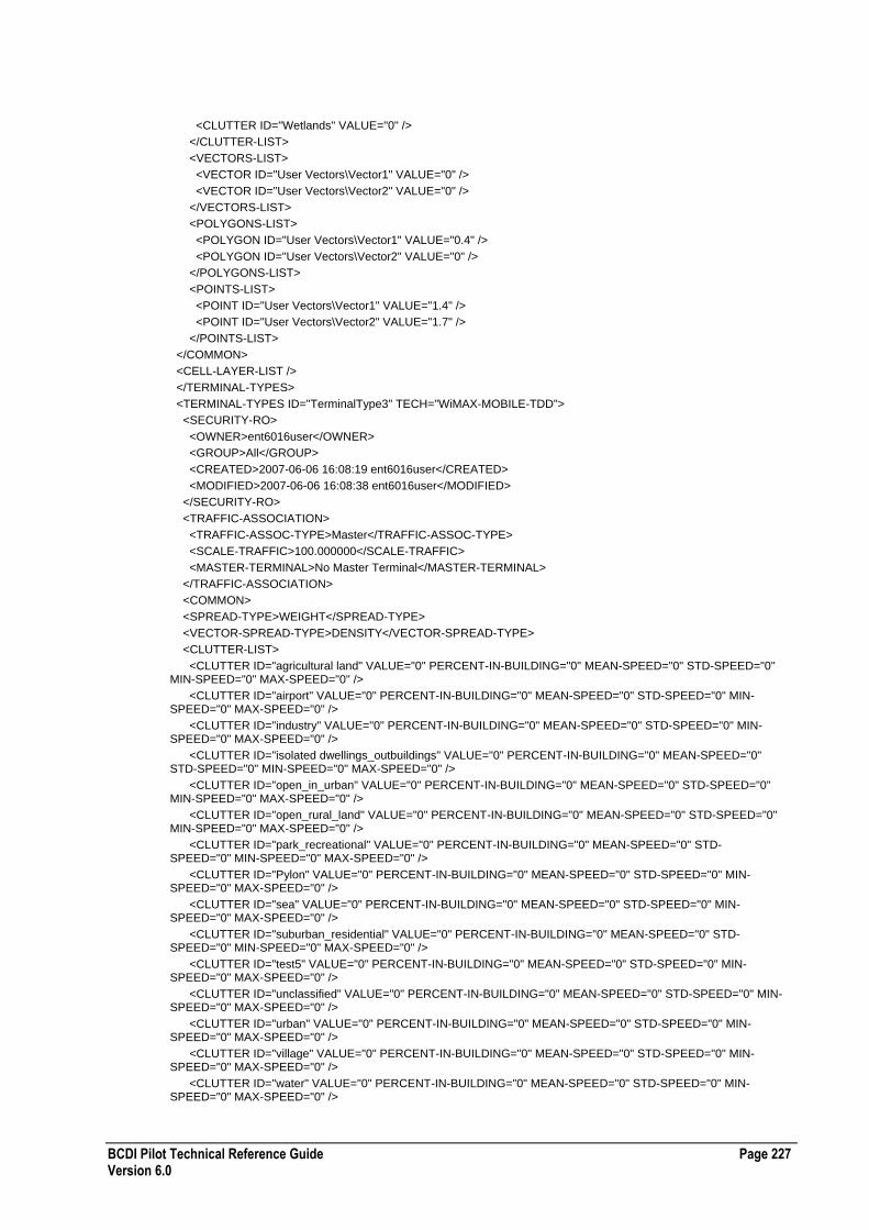
BCDI Pilot Technical Reference Guide Page 227 Version 6.0
<CLUTTER ID="Wetlands" VALUE="0" />
</CLUTTER-LIST>
<VECTORS-LIST>
<VECTOR ID="User Vectors\Vector1" VALUE="0" />
<VECTOR ID="User Vectors\Vector2" VALUE="0" />
</VECTORS-LIST>
<POLYGONS-LIST>
<POLYGON ID="User Vectors\Vector1" VALUE="0.4" />
<POLYGON ID="User Vectors\Vector2" VALUE="0" />
</POLYGONS-LIST>
<POINTS-LIST>
<POINT ID="User Vectors\Vector1" VALUE="1.4" />
<POINT ID="User Vectors\Vector2" VALUE="1.7" />
</POINTS-LIST>
</COMMON>
<CELL-LAYER-LIST />
</TERMINAL-TYPES>
<TERMINAL-TYPES ID="TerminalType3" TECH="WiMAX-MOBILE-TDD">
<SECURITY-RO>
<OWNER>ent6016user</OWNER>
<GROUP>All</GROUP>
<CREATED>2007-06-06 16:08:19 ent6016user</CREATED>
<MODIFIED>2007-06-06 16:08:38 ent6016user</MODIFIED>
</SECURITY-RO>
<TRAFFIC-ASSOCIATION>
<TRAFFIC-ASSOC-TYPE>Master</TRAFFIC-ASSOC-TYPE>
<SCALE-TRAFFIC>100.000000</SCALE-TRAFFIC>
<MASTER-TERMINAL>No Master Terminal</MASTER-TERMINAL>
</TRAFFIC-ASSOCIATION>
<COMMON>
<SPREAD-TYPE>WEIGHT</SPREAD-TYPE>
<VECTOR-SPREAD-TYPE>DENSITY</VECTOR-SPREAD-TYPE>
<CLUTTER-LIST>
<CLUTTER ID="agricultural land" VALUE="0" PERCENT-IN-BUILDING="0" MEAN-SPEED="0" STD-SPEED="0" MIN-SPEED="0" MAX-SPEED="0" />
<CLUTTER ID="airport" VALUE="0" PERCENT-IN-BUILDING="0" MEAN-SPEED="0" STD-SPEED="0" MIN-SPEED="0" MAX-SPEED="0" />
<CLUTTER ID="industry" VALUE="0" PERCENT-IN-BUILDING="0" MEAN-SPEED="0" STD-SPEED="0" MIN-SPEED="0" MAX-SPEED="0" />
<CLUTTER ID="isolated dwellings_outbuildings" VALUE="0" PERCENT-IN-BUILDING="0" MEAN-SPEED="0" STD-SPEED="0" MIN-SPEED="0" MAX-SPEED="0" />
<CLUTTER ID="open_in_urban" VALUE="0" PERCENT-IN-BUILDING="0" MEAN-SPEED="0" STD-SPEED="0" MIN-SPEED="0" MAX-SPEED="0" />
<CLUTTER ID="open_rural_land" VALUE="0" PERCENT-IN-BUILDING="0" MEAN-SPEED="0" STD-SPEED="0" MIN-SPEED="0" MAX-SPEED="0" />
<CLUTTER ID="park_recreational" VALUE="0" PERCENT-IN-BUILDING="0" MEAN-SPEED="0" STD-SPEED="0" MIN-SPEED="0" MAX-SPEED="0" />
<CLUTTER ID="Pylon" VALUE="0" PERCENT-IN-BUILDING="0" MEAN-SPEED="0" STD-SPEED="0" MIN-SPEED="0" MAX-SPEED="0" />
<CLUTTER ID="sea" VALUE="0" PERCENT-IN-BUILDING="0" MEAN-SPEED="0" STD-SPEED="0" MIN-SPEED="0" MAX-SPEED="0" />
<CLUTTER ID="suburban_residential" VALUE="0" PERCENT-IN-BUILDING="0" MEAN-SPEED="0" STD-SPEED="0" MIN-SPEED="0" MAX-SPEED="0" />
<CLUTTER ID="test5" VALUE="0" PERCENT-IN-BUILDING="0" MEAN-SPEED="0" STD-SPEED="0" MIN-SPEED="0" MAX-SPEED="0" />
<CLUTTER ID="unclassified" VALUE="0" PERCENT-IN-BUILDING="0" MEAN-SPEED="0" STD-SPEED="0" MIN-SPEED="0" MAX-SPEED="0" />
<CLUTTER ID="urban" VALUE="0" PERCENT-IN-BUILDING="0" MEAN-SPEED="0" STD-SPEED="0" MIN-SPEED="0" MAX-SPEED="0" />
<CLUTTER ID="village" VALUE="0" PERCENT-IN-BUILDING="0" MEAN-SPEED="0" STD-SPEED="0" MIN-SPEED="0" MAX-SPEED="0" />
<CLUTTER ID="water" VALUE="0" PERCENT-IN-BUILDING="0" MEAN-SPEED="0" STD-SPEED="0" MIN-SPEED="0" MAX-SPEED="0" />

Page 228 BCDI Pilot Technical Reference Guide Version 6.0
<CLUTTER ID="woodland_forest" VALUE="0" PERCENT-IN-BUILDING="0" MEAN-SPEED="0" STD-SPEED="0" MIN-SPEED="0" MAX-SPEED="0" />
</CLUTTER-LIST>
<VECTORS-LIST>
<VECTOR ID="System Vectors\System Vectors and Polygons\Transportation Features\Main Roads" VALUE="0" />
<VECTOR ID="System Vectors\System Vectors and Polygons\Geographic Features\Lakes" VALUE="0" />
<VECTOR ID="User Vectors\National Park" VALUE="0" />
<VECTOR ID="User Vectors\Vector1" VALUE="0" />
<VECTOR ID="System Vectors\System Vectors and Polygons\Geographic Features\Jersey Coast" VALUE="0" />
<VECTOR ID="System Vectors\System Vectors and Polygons\Transportation Features\Airport Runway" VALUE="0" />
<VECTOR ID="System Vectors\System Vectors and Polygons\Geographic Features\Europe Coast" VALUE="0" />
<VECTOR ID="User Vectors\Pathway" VALUE="0" />
<VECTOR ID="User Vectors\CityCentre" VALUE="0" />
<VECTOR ID="User Vectors\Vector2" VALUE="0" />
<VECTOR ID="System Vectors\System Vectors and Polygons\Transportation Features\Streets" VALUE="0" />
<VECTOR ID="System Vectors\System Vectors and Polygons\Buildings\Building Outlines" VALUE="0" />
<VECTOR ID="System Vectors\System Vectors and Polygons\Transportation Features\Minor Roads" VALUE="0" />
</VECTORS-LIST>
<POLYGONS-LIST>
<POLYGON ID="System Vectors\System Vectors and Polygons\Transportation Features\Main Roads" VALUE="0" />
<POLYGON ID="System Vectors\System Vectors and Polygons\Geographic Features\Lakes" VALUE="0" />
<POLYGON ID="User Vectors\National Park" VALUE="0" />
<POLYGON ID="User Vectors\Vector1" VALUE="0" />
<POLYGON ID="System Vectors\System Vectors and Polygons\Geographic Features\Jersey Coast" VALUE="0" />
<POLYGON ID="System Vectors\System Vectors and Polygons\Transportation Features\Airport Runway" VALUE="0" />
<POLYGON ID="System Vectors\System Vectors and Polygons\Geographic Features\Europe Coast" VALUE="0" />
<POLYGON ID="User Vectors\Pathway" VALUE="0" />
<POLYGON ID="User Vectors\CityCentre" VALUE="0" />
<POLYGON ID="User Vectors\Vector2" VALUE="0" />
<POLYGON ID="System Vectors\System Vectors and Polygons\Transportation Features\Streets" VALUE="0" />
<POLYGON ID="System Vectors\System Vectors and Polygons\Buildings\Building Outlines" VALUE="0" />
<POLYGON ID="System Vectors\System Vectors and Polygons\Transportation Features\Minor Roads" VALUE="0" />
</POLYGONS-LIST>
<POINTS-LIST>
<POINT ID="System Vectors\System Vectors and Polygons\Transportation Features\Main Roads" VALUE="0" />
<POINT ID="System Vectors\System Vectors and Polygons\Geographic Features\Lakes" VALUE="0" />
<POINT ID="User Vectors\National Park" VALUE="0" />
<POINT ID="User Vectors\Vector1" VALUE="0" />
<POINT ID="System Vectors\System Vectors and Polygons\Geographic Features\Jersey Coast" VALUE="0" />
<POINT ID="System Vectors\System Vectors and Polygons\Transportation Features\Airport Runway" VALUE="0" />
<POINT ID="System Vectors\System Vectors and Polygons\Geographic Features\Europe Coast" VALUE="0" />
<POINT ID="User Vectors\Pathway" VALUE="0" />
<POINT ID="User Vectors\CityCentre" VALUE="0" />
<POINT ID="User Vectors\Vector2" VALUE="0" />
<POINT ID="System Vectors\System Vectors and Polygons\Transportation Features\Streets" VALUE="0" />
<POINT ID="System Vectors\System Vectors and Polygons\Buildings\Building Outlines" VALUE="0" />
<POINT ID="System Vectors\System Vectors and Polygons\Transportation Features\Minor Roads" VALUE="0" />
</POINTS-LIST>
</COMMON>
<PARAMS>
<REQ-PILOT-RSS>-102.000000</REQ-PILOT-RSS>
<MAX-MOBILE-PWR>21.000000</MAX-MOBILE-PWR>
<ANTENNA-GAIN>0.000000</ANTENNA-GAIN>
<NOISE-FIGURE>0.000000</NOISE-FIGURE>
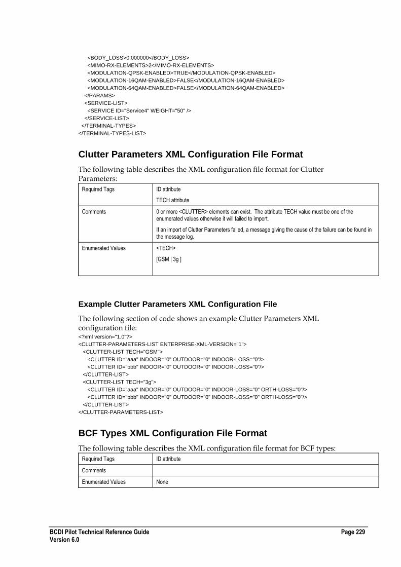
BCDI Pilot Technical Reference Guide Page 229 Version 6.0
<BODY_LOSS>0.000000</BODY_LOSS>
<MIMO-RX-ELEMENTS>2</MIMO-RX-ELEMENTS>
<MODULATION-QPSK-ENABLED>TRUE</MODULATION-QPSK-ENABLED>
<MODULATION-16QAM-ENABLED>FALSE</MODULATION-16QAM-ENABLED>
<MODULATION-64QAM-ENABLED>FALSE</MODULATION-64QAM-ENABLED>
</PARAMS>
<SERVICE-LIST>
<SERVICE ID="Service4" WEIGHT="50" />
</SERVICE-LIST>
</TERMINAL-TYPES>
</TERMINAL-TYPES-LIST>
Clutter Parameters XML Configuration File Format
The following table describes the XML configuration file format for Clutter Parameters:
Required Tags ID attribute
TECH attribute
Comments 0 or more <CLUTTER> elements can exist. The attribute TECH value must be one of the enumerated values otherwise it will failed to import.
If an import of Clutter Parameters failed, a message giving the cause of the failure can be found in the message log.
Enumerated Values <TECH>
[GSM | 3g ]
Example Clutter Parameters XML Configuration File
The following section of code shows an example Clutter Parameters XML configuration file: <?xml version="1.0"?>
<CLUTTER-PARAMETERS-LIST ENTERPRISE-XML-VERSION="1">
<CLUTTER-LIST TECH="GSM">
<CLUTTER ID="aaa" INDOOR="0" OUTDOOR="0" INDOOR-LOSS="0"/>
<CLUTTER ID="bbb" INDOOR="0" OUTDOOR="0" INDOOR-LOSS="0"/>
</CLUTTER-LIST>
<CLUTTER-LIST TECH="3g">
<CLUTTER ID="aaa" INDOOR="0" OUTDOOR="0" INDOOR-LOSS="0" ORTH-LOSS="0"/>
<CLUTTER ID="bbb" INDOOR="0" OUTDOOR="0" INDOOR-LOSS="0" ORTH-LOSS="0"/>
</CLUTTER-LIST>
</CLUTTER-PARAMETERS-LIST>
BCF Types XML Configuration File Format
The following table describes the XML configuration file format for BCF types:
Required Tags ID attribute
Comments
Enumerated Values None
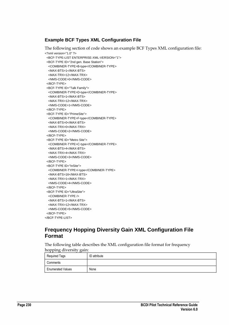
Page 230 BCDI Pilot Technical Reference Guide Version 6.0
Example BCF Types XML Configuration File
The following section of code shows an example BCF Types XML configuration file: <?xml version="1.0" ?>
<BCF-TYPE-LIST ENTERPRISE-XML-VERSION="1">
<BCF-TYPE ID="2nd gen. Base Station">
<COMBINER-TYPE>B-type</COMBINER-TYPE>
<MAX-BTS>1</MAX-BTS>
<MAX-TRX>12</MAX-TRX>
<NMS-CODE>0</NMS-CODE>
</BCF-TYPE>
<BCF-TYPE ID="Talk Family">
<COMBINER-TYPE>D-type</COMBINER-TYPE>
<MAX-BTS>1</MAX-BTS>
<MAX-TRX>12</MAX-TRX>
<NMS-CODE>1</NMS-CODE>
</BCF-TYPE>
<BCF-TYPE ID="PrimeSite">
<COMBINER-TYPE>F-type</COMBINER-TYPE>
<MAX-BTS>0</MAX-BTS>
<MAX-TRX>0</MAX-TRX>
<NMS-CODE>2</NMS-CODE>
</BCF-TYPE>
<BCF-TYPE ID="Metro Site">
<COMBINER-TYPE>C-type</COMBINER-TYPE>
<MAX-BTS>4</MAX-BTS>
<MAX-TRX>4</MAX-TRX>
<NMS-CODE>3</NMS-CODE>
</BCF-TYPE>
<BCF-TYPE ID="InSite">
<COMBINER-TYPE>I-type</COMBINER-TYPE>
<MAX-BTS>16</MAX-BTS>
<MAX-TRX>1</MAX-TRX>
<NMS-CODE>4</NMS-CODE>
</BCF-TYPE>
<BCF-TYPE ID="UltraSite">
<COMBINER-TYPE />
<MAX-BTS>1</MAX-BTS>
<MAX-TRX>12</MAX-TRX>
<NMS-CODE>5</NMS-CODE>
</BCF-TYPE>
</BCF-TYPE-LIST>
Frequency Hopping Diversity Gain XML Configuration File Format
The following table describes the XML configuration file format for frequency hopping diversity gain:
Required Tags ID attribute
Comments
Enumerated Values None

BCDI Pilot Technical Reference Guide Page 231 Version 6.0
Example Frequency Hopping Diversity Gain XML Configuration File
The following section of code shows an example frequency hopping diversity gain XML configuration file: <?xml version="1.0" ?>
<FREQ-HOP-DIV-GAIN-LIST ENTERPRISE-XML-VERSION="1">
<FREQ-HOP-DIV-GAIN ID="1" GAIN="0.00000" />
<FREQ-HOP-DIV-GAIN ID="2" GAIN="3.00000" />
<FREQ-HOP-DIV-GAIN ID="3" GAIN="4.00000" />
<FREQ-HOP-DIV-GAIN ID="4" GAIN="5.00000" />
<FREQ-HOP-DIV-GAIN ID="5" GAIN="5.50000" />
<FREQ-HOP-DIV-GAIN ID="6" GAIN="6.00000" />
<FREQ-HOP-DIV-GAIN ID="7" GAIN="6.30000" />
<FREQ-HOP-DIV-GAIN ID="8" GAIN="6.50000" />
<FREQ-HOP-DIV-GAIN ID="9" GAIN="6.80000" />
<FREQ-HOP-DIV-GAIN ID="10" GAIN="6.90000" />
<FREQ-HOP-DIV-GAIN ID="11" GAIN="7.00000" />
</FREQ-HOP-DIV-GAIN-LIST>
CI BER Conversion XML Configuration File Format
The following table describes the XML configuration file format for CI BER conversion:
Required Tags ID attribute
Comments
Enumerated Values None
Example CI BER Conversion XML Configuration File
The following section of code shows an example CI BER conversion XML configuration file: <?xml version="1.0" ?>
<CI-BER-CONVERSION-LIST ENTERPRISE-XML-VERSION="1">
<CI-BER-CONVERSION ID="-10" BER="0.5000000000" />
<CI-BER-CONVERSION ID="-9" BER="0.4880000000" />
<CI-BER-CONVERSION ID="-8" BER="0.4650000000" />
<CI-BER-CONVERSION ID="-7" BER="0.4300000000" />
<CI-BER-CONVERSION ID="-6" BER="0.3880000000" />
<CI-BER-CONVERSION ID="-5" BER="0.3500000000" />
<CI-BER-CONVERSION ID="-4" BER="0.3200000000" />
<CI-BER-CONVERSION ID="-3" BER="0.3000000000" />
<CI-BER-CONVERSION ID="-2" BER="0.2700000000" />
<CI-BER-CONVERSION ID="-1" BER="0.2500000000" />
<CI-BER-CONVERSION ID="0" BER="0.2200000000" />
<CI-BER-CONVERSION ID="1" BER="0.2000000000" />
<CI-BER-CONVERSION ID="2" BER="0.1700000000" />
<CI-BER-CONVERSION ID="3" BER="0.1500000000" />
<CI-BER-CONVERSION ID="4" BER="0.1200000000" />
<CI-BER-CONVERSION ID="5" BER="0.1000000000" />
<CI-BER-CONVERSION ID="6" BER="0.0900000000" />
<CI-BER-CONVERSION ID="7" BER="0.0780000000" />
<CI-BER-CONVERSION ID="8" BER="0.0660000000" />
<CI-BER-CONVERSION ID="9" BER="0.0550000000" />
<CI-BER-CONVERSION ID="10" BER="0.0450000000" />
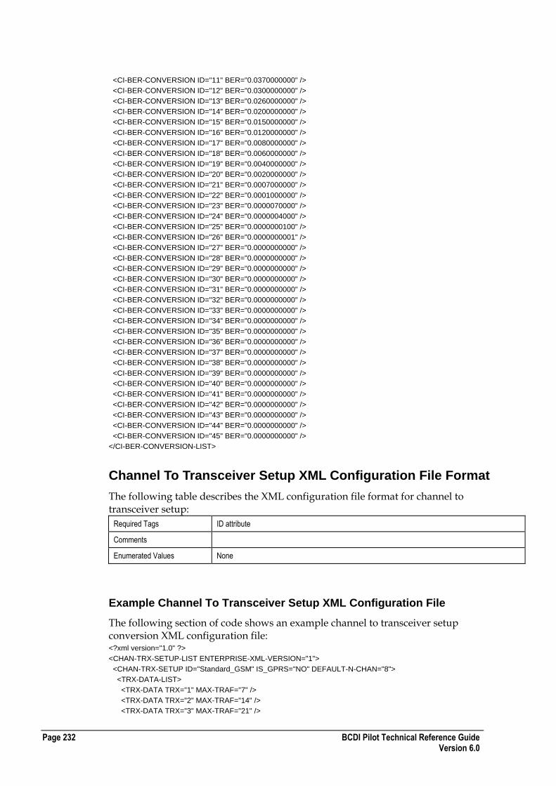
Page 232 BCDI Pilot Technical Reference Guide Version 6.0
<CI-BER-CONVERSION ID="11" BER="0.0370000000" />
<CI-BER-CONVERSION ID="12" BER="0.0300000000" />
<CI-BER-CONVERSION ID="13" BER="0.0260000000" />
<CI-BER-CONVERSION ID="14" BER="0.0200000000" />
<CI-BER-CONVERSION ID="15" BER="0.0150000000" />
<CI-BER-CONVERSION ID="16" BER="0.0120000000" />
<CI-BER-CONVERSION ID="17" BER="0.0080000000" />
<CI-BER-CONVERSION ID="18" BER="0.0060000000" />
<CI-BER-CONVERSION ID="19" BER="0.0040000000" />
<CI-BER-CONVERSION ID="20" BER="0.0020000000" />
<CI-BER-CONVERSION ID="21" BER="0.0007000000" />
<CI-BER-CONVERSION ID="22" BER="0.0001000000" />
<CI-BER-CONVERSION ID="23" BER="0.0000070000" />
<CI-BER-CONVERSION ID="24" BER="0.0000004000" />
<CI-BER-CONVERSION ID="25" BER="0.0000000100" />
<CI-BER-CONVERSION ID="26" BER="0.0000000001" />
<CI-BER-CONVERSION ID="27" BER="0.0000000000" />
<CI-BER-CONVERSION ID="28" BER="0.0000000000" />
<CI-BER-CONVERSION ID="29" BER="0.0000000000" />
<CI-BER-CONVERSION ID="30" BER="0.0000000000" />
<CI-BER-CONVERSION ID="31" BER="0.0000000000" />
<CI-BER-CONVERSION ID="32" BER="0.0000000000" />
<CI-BER-CONVERSION ID="33" BER="0.0000000000" />
<CI-BER-CONVERSION ID="34" BER="0.0000000000" />
<CI-BER-CONVERSION ID="35" BER="0.0000000000" />
<CI-BER-CONVERSION ID="36" BER="0.0000000000" />
<CI-BER-CONVERSION ID="37" BER="0.0000000000" />
<CI-BER-CONVERSION ID="38" BER="0.0000000000" />
<CI-BER-CONVERSION ID="39" BER="0.0000000000" />
<CI-BER-CONVERSION ID="40" BER="0.0000000000" />
<CI-BER-CONVERSION ID="41" BER="0.0000000000" />
<CI-BER-CONVERSION ID="42" BER="0.0000000000" />
<CI-BER-CONVERSION ID="43" BER="0.0000000000" />
<CI-BER-CONVERSION ID="44" BER="0.0000000000" />
<CI-BER-CONVERSION ID="45" BER="0.0000000000" />
</CI-BER-CONVERSION-LIST>
Channel To Transceiver Setup XML Configuration File Format
The following table describes the XML configuration file format for channel to transceiver setup:
Required Tags ID attribute
Comments
Enumerated Values None
Example Channel To Transceiver Setup XML Configuration File
The following section of code shows an example channel to transceiver setup conversion XML configuration file: <?xml version="1.0" ?>
<CHAN-TRX-SETUP-LIST ENTERPRISE-XML-VERSION="1">
<CHAN-TRX-SETUP ID="Standard_GSM" IS_GPRS="NO" DEFAULT-N-CHAN="8">
<TRX-DATA-LIST>
<TRX-DATA TRX="1" MAX-TRAF="7" />
<TRX-DATA TRX="2" MAX-TRAF="14" />
<TRX-DATA TRX="3" MAX-TRAF="21" />
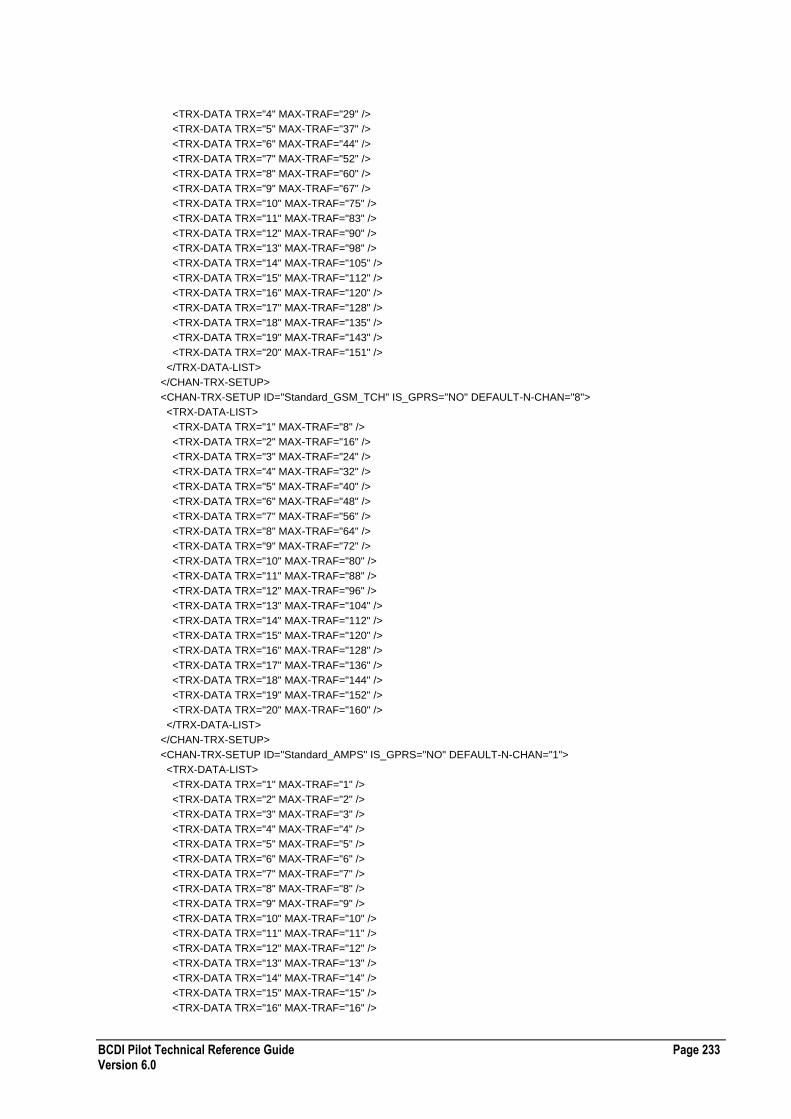
BCDI Pilot Technical Reference Guide Page 233 Version 6.0
<TRX-DATA TRX="4" MAX-TRAF="29" />
<TRX-DATA TRX="5" MAX-TRAF="37" />
<TRX-DATA TRX="6" MAX-TRAF="44" />
<TRX-DATA TRX="7" MAX-TRAF="52" />
<TRX-DATA TRX="8" MAX-TRAF="60" />
<TRX-DATA TRX="9" MAX-TRAF="67" />
<TRX-DATA TRX="10" MAX-TRAF="75" />
<TRX-DATA TRX="11" MAX-TRAF="83" />
<TRX-DATA TRX="12" MAX-TRAF="90" />
<TRX-DATA TRX="13" MAX-TRAF="98" />
<TRX-DATA TRX="14" MAX-TRAF="105" />
<TRX-DATA TRX="15" MAX-TRAF="112" />
<TRX-DATA TRX="16" MAX-TRAF="120" />
<TRX-DATA TRX="17" MAX-TRAF="128" />
<TRX-DATA TRX="18" MAX-TRAF="135" />
<TRX-DATA TRX="19" MAX-TRAF="143" />
<TRX-DATA TRX="20" MAX-TRAF="151" />
</TRX-DATA-LIST>
</CHAN-TRX-SETUP>
<CHAN-TRX-SETUP ID="Standard_GSM_TCH" IS_GPRS="NO" DEFAULT-N-CHAN="8">
<TRX-DATA-LIST>
<TRX-DATA TRX="1" MAX-TRAF="8" />
<TRX-DATA TRX="2" MAX-TRAF="16" />
<TRX-DATA TRX="3" MAX-TRAF="24" />
<TRX-DATA TRX="4" MAX-TRAF="32" />
<TRX-DATA TRX="5" MAX-TRAF="40" />
<TRX-DATA TRX="6" MAX-TRAF="48" />
<TRX-DATA TRX="7" MAX-TRAF="56" />
<TRX-DATA TRX="8" MAX-TRAF="64" />
<TRX-DATA TRX="9" MAX-TRAF="72" />
<TRX-DATA TRX="10" MAX-TRAF="80" />
<TRX-DATA TRX="11" MAX-TRAF="88" />
<TRX-DATA TRX="12" MAX-TRAF="96" />
<TRX-DATA TRX="13" MAX-TRAF="104" />
<TRX-DATA TRX="14" MAX-TRAF="112" />
<TRX-DATA TRX="15" MAX-TRAF="120" />
<TRX-DATA TRX="16" MAX-TRAF="128" />
<TRX-DATA TRX="17" MAX-TRAF="136" />
<TRX-DATA TRX="18" MAX-TRAF="144" />
<TRX-DATA TRX="19" MAX-TRAF="152" />
<TRX-DATA TRX="20" MAX-TRAF="160" />
</TRX-DATA-LIST>
</CHAN-TRX-SETUP>
<CHAN-TRX-SETUP ID="Standard_AMPS" IS_GPRS="NO" DEFAULT-N-CHAN="1">
<TRX-DATA-LIST>
<TRX-DATA TRX="1" MAX-TRAF="1" />
<TRX-DATA TRX="2" MAX-TRAF="2" />
<TRX-DATA TRX="3" MAX-TRAF="3" />
<TRX-DATA TRX="4" MAX-TRAF="4" />
<TRX-DATA TRX="5" MAX-TRAF="5" />
<TRX-DATA TRX="6" MAX-TRAF="6" />
<TRX-DATA TRX="7" MAX-TRAF="7" />
<TRX-DATA TRX="8" MAX-TRAF="8" />
<TRX-DATA TRX="9" MAX-TRAF="9" />
<TRX-DATA TRX="10" MAX-TRAF="10" />
<TRX-DATA TRX="11" MAX-TRAF="11" />
<TRX-DATA TRX="12" MAX-TRAF="12" />
<TRX-DATA TRX="13" MAX-TRAF="13" />
<TRX-DATA TRX="14" MAX-TRAF="14" />
<TRX-DATA TRX="15" MAX-TRAF="15" />
<TRX-DATA TRX="16" MAX-TRAF="16" />
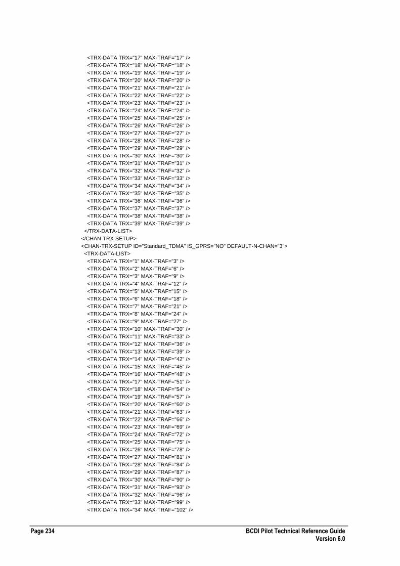
Page 234 BCDI Pilot Technical Reference Guide Version 6.0
<TRX-DATA TRX="17" MAX-TRAF="17" />
<TRX-DATA TRX="18" MAX-TRAF="18" />
<TRX-DATA TRX="19" MAX-TRAF="19" />
<TRX-DATA TRX="20" MAX-TRAF="20" />
<TRX-DATA TRX="21" MAX-TRAF="21" />
<TRX-DATA TRX="22" MAX-TRAF="22" />
<TRX-DATA TRX="23" MAX-TRAF="23" />
<TRX-DATA TRX="24" MAX-TRAF="24" />
<TRX-DATA TRX="25" MAX-TRAF="25" />
<TRX-DATA TRX="26" MAX-TRAF="26" />
<TRX-DATA TRX="27" MAX-TRAF="27" />
<TRX-DATA TRX="28" MAX-TRAF="28" />
<TRX-DATA TRX="29" MAX-TRAF="29" />
<TRX-DATA TRX="30" MAX-TRAF="30" />
<TRX-DATA TRX="31" MAX-TRAF="31" />
<TRX-DATA TRX="32" MAX-TRAF="32" />
<TRX-DATA TRX="33" MAX-TRAF="33" />
<TRX-DATA TRX="34" MAX-TRAF="34" />
<TRX-DATA TRX="35" MAX-TRAF="35" />
<TRX-DATA TRX="36" MAX-TRAF="36" />
<TRX-DATA TRX="37" MAX-TRAF="37" />
<TRX-DATA TRX="38" MAX-TRAF="38" />
<TRX-DATA TRX="39" MAX-TRAF="39" />
</TRX-DATA-LIST>
</CHAN-TRX-SETUP>
<CHAN-TRX-SETUP ID="Standard_TDMA" IS_GPRS="NO" DEFAULT-N-CHAN="3">
<TRX-DATA-LIST>
<TRX-DATA TRX="1" MAX-TRAF="3" />
<TRX-DATA TRX="2" MAX-TRAF="6" />
<TRX-DATA TRX="3" MAX-TRAF="9" />
<TRX-DATA TRX="4" MAX-TRAF="12" />
<TRX-DATA TRX="5" MAX-TRAF="15" />
<TRX-DATA TRX="6" MAX-TRAF="18" />
<TRX-DATA TRX="7" MAX-TRAF="21" />
<TRX-DATA TRX="8" MAX-TRAF="24" />
<TRX-DATA TRX="9" MAX-TRAF="27" />
<TRX-DATA TRX="10" MAX-TRAF="30" />
<TRX-DATA TRX="11" MAX-TRAF="33" />
<TRX-DATA TRX="12" MAX-TRAF="36" />
<TRX-DATA TRX="13" MAX-TRAF="39" />
<TRX-DATA TRX="14" MAX-TRAF="42" />
<TRX-DATA TRX="15" MAX-TRAF="45" />
<TRX-DATA TRX="16" MAX-TRAF="48" />
<TRX-DATA TRX="17" MAX-TRAF="51" />
<TRX-DATA TRX="18" MAX-TRAF="54" />
<TRX-DATA TRX="19" MAX-TRAF="57" />
<TRX-DATA TRX="20" MAX-TRAF="60" />
<TRX-DATA TRX="21" MAX-TRAF="63" />
<TRX-DATA TRX="22" MAX-TRAF="66" />
<TRX-DATA TRX="23" MAX-TRAF="69" />
<TRX-DATA TRX="24" MAX-TRAF="72" />
<TRX-DATA TRX="25" MAX-TRAF="75" />
<TRX-DATA TRX="26" MAX-TRAF="78" />
<TRX-DATA TRX="27" MAX-TRAF="81" />
<TRX-DATA TRX="28" MAX-TRAF="84" />
<TRX-DATA TRX="29" MAX-TRAF="87" />
<TRX-DATA TRX="30" MAX-TRAF="90" />
<TRX-DATA TRX="31" MAX-TRAF="93" />
<TRX-DATA TRX="32" MAX-TRAF="96" />
<TRX-DATA TRX="33" MAX-TRAF="99" />
<TRX-DATA TRX="34" MAX-TRAF="102" />

BCDI Pilot Technical Reference Guide Page 235 Version 6.0
<TRX-DATA TRX="35" MAX-TRAF="105" />
<TRX-DATA TRX="36" MAX-TRAF="108" />
<TRX-DATA TRX="37" MAX-TRAF="111" />
<TRX-DATA TRX="38" MAX-TRAF="114" />
<TRX-DATA TRX="39" MAX-TRAF="117" />
</TRX-DATA-LIST>
</CHAN-TRX-SETUP>
<CHAN-TRX-SETUP ID="Standard_TETRA" IS_GPRS="NO" DEFAULT-N-CHAN="4">
<TRX-DATA-LIST>
<TRX-DATA TRX="1" MAX-TRAF="3" />
<TRX-DATA TRX="2" MAX-TRAF="7" />
<TRX-DATA TRX="3" MAX-TRAF="11" />
<TRX-DATA TRX="4" MAX-TRAF="15" />
<TRX-DATA TRX="5" MAX-TRAF="18" />
<TRX-DATA TRX="6" MAX-TRAF="22" />
<TRX-DATA TRX="7" MAX-TRAF="26" />
<TRX-DATA TRX="8" MAX-TRAF="30" />
<TRX-DATA TRX="9" MAX-TRAF="33" />
<TRX-DATA TRX="10" MAX-TRAF="37" />
</TRX-DATA-LIST>
</CHAN-TRX-SETUP>
</CHAN-TRX-SETUP-LIST>
GPRS Data Throughput XML Configuration File Format
The following table describes the XML configuration file format for GPRS data throughput:
Required Tags GPRS-MCS-CURVE TYPE
Comments
Enumerated Values USE-FH
Example GPRS Data Throughput XML Configuration File
The following section of code shows an example GPRS data throughput XML configuration file: <?xml version="1.0" ?>
<GPRS-MCS-CURVE-LIST ENTERPRISE-XML-VERSION="1" USE-FH="NO">
<GPRS-MCS-CURVE TYPE="GPRS">
<DATA-LIST>
<DATA>
<CI-DB>0.000000</CI-DB>
<CCS-1>2.582870</CCS-1>
<CCS-2>1.452560</CCS-2>
<CCS-3>0.907920</CCS-3>
<CCS-4>0.124120</CCS-4>
</DATA>
<DATA>
<CI-DB>2.000000</CI-DB>
<CCS-1>4.184720</CCS-1>
<CCS-2>2.894400</CCS-2>
<CCS-3>2.021760</CCS-3>
<CCS-4>0.410880</CCS-4>
</DATA>
<DATA>
<CI-DB>4.000000</CI-DB>
<CCS-1>5.735890</CCS-1>

Page 236 BCDI Pilot Technical Reference Guide Version 6.0
<CCS-2>4.952640</CCS-2>
<CCS-3>3.744000</CCS-3>
<CCS-4>0.984400</CCS-4>
</DATA>
<DATA>
<CI-DB>6.000000</CI-DB>
<CCS-1>7.102440</CCS-1>
<CCS-2>7.214560</CCS-2>
<CCS-3>6.165120</CCS-3>
<CCS-4>2.208480</CCS-4>
</DATA>
<DATA>
<CI-DB>8.000000</CI-DB>
<CCS-1>8.117850</CCS-1>
<CCS-2>9.227240</CCS-2>
<CCS-3>8.633040</CCS-3>
<CCS-4>4.211520</CCS-4>
</DATA>
<DATA>
<CI-DB>10.000000</CI-DB>
<CCS-1>8.639130</CCS-1>
<CCS-2>11.148800</CCS-2>
<CCS-3>10.976200</CCS-3>
<CCS-4>6.942160</CCS-4>
</DATA>
<DATA>
<CI-DB>12.000000</CI-DB>
<CCS-1>8.903390</CCS-1>
<CCS-2>12.320000</CCS-2>
<CCS-3>13.029100</CCS-3>
<CCS-4>9.899640</CCS-4>
</DATA>
<DATA>
<CI-DB>14.000000</CI-DB>
<CCS-1>8.990270</CCS-1>
<CCS-2>12.947100</CCS-2>
<CCS-3>14.261500</CCS-3>
<CCS-4>12.912800</CCS-4>
</DATA>
<DATA>
<CI-DB>16.000000</CI-DB>
<CCS-1>9.033710</CCS-1>
<CCS-2>13.239200</CCS-2>
<CCS-3>14.997800</CCS-3>
<CCS-4>15.639100</CCS-4>
</DATA>
<DATA>
<CI-DB>18.000000</CI-DB>
<CCS-1>9.050000</CCS-1>
<CCS-2>13.338400</CCS-2>
<CCS-3>15.381600</CCS-3>
<CCS-4>17.552299</CCS-4>
</DATA>
<DATA>
<CI-DB>20.000000</CI-DB>
<CCS-1>9.050000</CCS-1>
<CCS-2>13.383900</CCS-2>
<CCS-3>15.531400</CCS-3>
<CCS-4>18.981800</CCS-4>
</DATA>
<DATA>
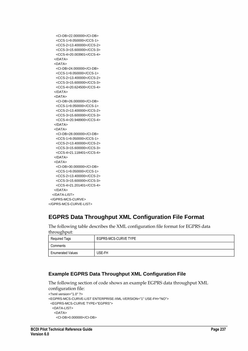
BCDI Pilot Technical Reference Guide Page 237 Version 6.0
<CI-DB>22.000000</CI-DB>
<CCS-1>9.050000</CCS-1>
<CCS-2>13.400000</CCS-2>
<CCS-3>15.600000</CCS-3>
<CCS-4>20.003901</CCS-4>
</DATA>
<DATA>
<CI-DB>24.000000</CI-DB>
<CCS-1>9.050000</CCS-1>
<CCS-2>13.400000</CCS-2>
<CCS-3>15.600000</CCS-3>
<CCS-4>20.624500</CCS-4>
</DATA>
<DATA>
<CI-DB>26.000000</CI-DB>
<CCS-1>9.050000</CCS-1>
<CCS-2>13.400000</CCS-2>
<CCS-3>15.600000</CCS-3>
<CCS-4>20.948900</CCS-4>
</DATA>
<DATA>
<CI-DB>28.000000</CI-DB>
<CCS-1>9.050000</CCS-1>
<CCS-2>13.400000</CCS-2>
<CCS-3>15.600000</CCS-3>
<CCS-4>21.118401</CCS-4>
</DATA>
<DATA>
<CI-DB>30.000000</CI-DB>
<CCS-1>9.050000</CCS-1>
<CCS-2>13.400000</CCS-2>
<CCS-3>15.600000</CCS-3>
<CCS-4>21.201401</CCS-4>
</DATA>
</DATA-LIST>
</GPRS-MCS-CURVE>
</GPRS-MCS-CURVE-LIST>
EGPRS Data Throughput XML Configuration File Format
The following table describes the XML configuration file format for EGPRS data throughput:
Required Tags EGPRS-MCS-CURVE TYPE
Comments
Enumerated Values USE-FH
Example EGPRS Data Throughput XML Configuration File
The following section of code shows an example EGPRS data throughput XML configuration file: <?xml version="1.0" ?>
<EGPRS-MCS-CURVE-LIST ENTERPRISE-XML-VERSION="1" USE-FH="NO">
<EGPRS-MCS-CURVE TYPE="EGPRS">
<DATA-LIST>
<DATA>
<CI-DB>0.000000</CI-DB>

Page 238 BCDI Pilot Technical Reference Guide Version 6.0
<MCS-1>2.582870</MCS-1>
<MCS-2>1.452560</MCS-2>
<MCS-3>0.907920</MCS-3>
<MCS-4>0.124120</MCS-4>
<MCS-5>0.000000</MCS-5>
<MCS-6>0.000000</MCS-6>
<MCS-7>0.000000</MCS-7>
<MCS-8>0.000000</MCS-8>
<MCS-9>0.000000</MCS-9>
</DATA>
<DATA>
<CI-DB>2.000000</CI-DB>
<MCS-1>4.184720</MCS-1>
<MCS-2>2.894400</MCS-2>
<MCS-3>2.021760</MCS-3>
<MCS-4>0.410880</MCS-4>
<MCS-5>0.000000</MCS-5>
<MCS-6>0.000000</MCS-6>
<MCS-7>0.000000</MCS-7>
<MCS-8>0.000000</MCS-8>
<MCS-9>0.000000</MCS-9>
</DATA>
<DATA>
<CI-DB>4.000000</CI-DB>
<MCS-1>5.735890</MCS-1>
<MCS-2>4.952640</MCS-2>
<MCS-3>3.744000</MCS-3>
<MCS-4>0.984400</MCS-4>
<MCS-5>0.000000</MCS-5>
<MCS-6>0.000000</MCS-6>
<MCS-7>0.000000</MCS-7>
<MCS-8>0.000000</MCS-8>
<MCS-9>0.000000</MCS-9>
</DATA>
<DATA>
<CI-DB>6.000000</CI-DB>
<MCS-1>7.102440</MCS-1>
<MCS-2>7.214560</MCS-2>
<MCS-3>6.165120</MCS-3>
<MCS-4>2.208480</MCS-4>
<MCS-5>0.000000</MCS-5>
<MCS-6>0.000000</MCS-6>
<MCS-7>0.000000</MCS-7>
<MCS-8>0.200000</MCS-8>
<MCS-9>0.000000</MCS-9>
</DATA>
<DATA>
<CI-DB>8.000000</CI-DB>
<MCS-1>8.117850</MCS-1>
<MCS-2>9.227240</MCS-2>
<MCS-3>8.633040</MCS-3>
<MCS-4>4.211520</MCS-4>
<MCS-5>8.600000</MCS-5>
<MCS-6>0.000000</MCS-6>
<MCS-7>0.000000</MCS-7>
<MCS-8>0.500000</MCS-8>
<MCS-9>0.000000</MCS-9>
</DATA>
<DATA>
<CI-DB>10.000000</CI-DB>
<MCS-1>8.639130</MCS-1>
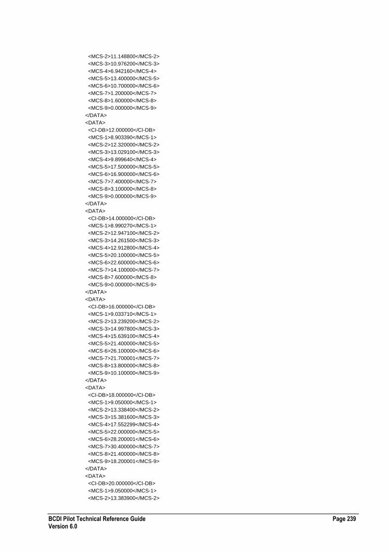
BCDI Pilot Technical Reference Guide Page 239 Version 6.0
<MCS-2>11.148800</MCS-2>
<MCS-3>10.976200</MCS-3>
<MCS-4>6.942160</MCS-4>
<MCS-5>13.400000</MCS-5>
<MCS-6>10.700000</MCS-6>
<MCS-7>1.200000</MCS-7>
<MCS-8>1.600000</MCS-8>
<MCS-9>0.000000</MCS-9>
</DATA>
<DATA>
<CI-DB>12.000000</CI-DB>
<MCS-1>8.903390</MCS-1>
<MCS-2>12.320000</MCS-2>
<MCS-3>13.029100</MCS-3>
<MCS-4>9.899640</MCS-4>
<MCS-5>17.500000</MCS-5>
<MCS-6>16.900000</MCS-6>
<MCS-7>7.400000</MCS-7>
<MCS-8>3.100000</MCS-8>
<MCS-9>0.000000</MCS-9>
</DATA>
<DATA>
<CI-DB>14.000000</CI-DB>
<MCS-1>8.990270</MCS-1>
<MCS-2>12.947100</MCS-2>
<MCS-3>14.261500</MCS-3>
<MCS-4>12.912800</MCS-4>
<MCS-5>20.100000</MCS-5>
<MCS-6>22.600000</MCS-6>
<MCS-7>14.100000</MCS-7>
<MCS-8>7.600000</MCS-8>
<MCS-9>0.000000</MCS-9>
</DATA>
<DATA>
<CI-DB>16.000000</CI-DB>
<MCS-1>9.033710</MCS-1>
<MCS-2>13.239200</MCS-2>
<MCS-3>14.997800</MCS-3>
<MCS-4>15.639100</MCS-4>
<MCS-5>21.400000</MCS-5>
<MCS-6>26.100000</MCS-6>
<MCS-7>21.700001</MCS-7>
<MCS-8>13.800000</MCS-8>
<MCS-9>10.100000</MCS-9>
</DATA>
<DATA>
<CI-DB>18.000000</CI-DB>
<MCS-1>9.050000</MCS-1>
<MCS-2>13.338400</MCS-2>
<MCS-3>15.381600</MCS-3>
<MCS-4>17.552299</MCS-4>
<MCS-5>22.000000</MCS-5>
<MCS-6>28.200001</MCS-6>
<MCS-7>30.400000</MCS-7>
<MCS-8>21.400000</MCS-8>
<MCS-9>18.200001</MCS-9>
</DATA>
<DATA>
<CI-DB>20.000000</CI-DB>
<MCS-1>9.050000</MCS-1>
<MCS-2>13.383900</MCS-2>
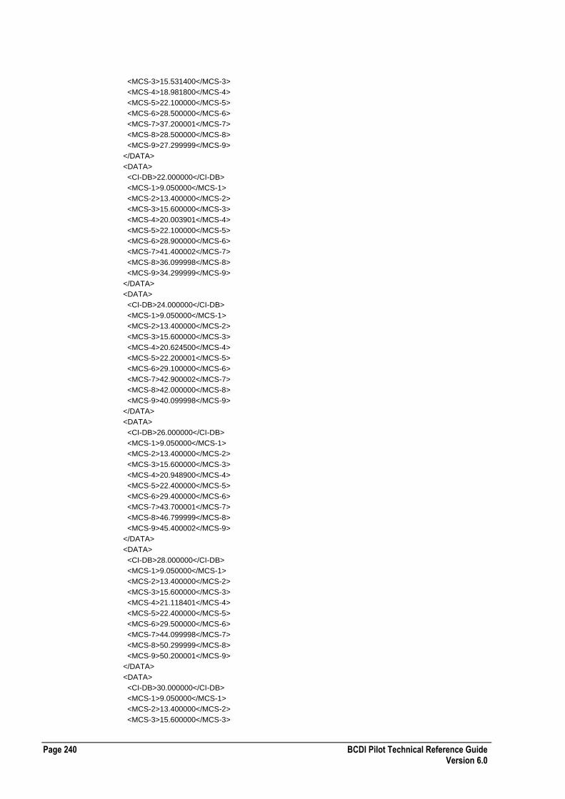
Page 240 BCDI Pilot Technical Reference Guide Version 6.0
<MCS-3>15.531400</MCS-3>
<MCS-4>18.981800</MCS-4>
<MCS-5>22.100000</MCS-5>
<MCS-6>28.500000</MCS-6>
<MCS-7>37.200001</MCS-7>
<MCS-8>28.500000</MCS-8>
<MCS-9>27.299999</MCS-9>
</DATA>
<DATA>
<CI-DB>22.000000</CI-DB>
<MCS-1>9.050000</MCS-1>
<MCS-2>13.400000</MCS-2>
<MCS-3>15.600000</MCS-3>
<MCS-4>20.003901</MCS-4>
<MCS-5>22.100000</MCS-5>
<MCS-6>28.900000</MCS-6>
<MCS-7>41.400002</MCS-7>
<MCS-8>36.099998</MCS-8>
<MCS-9>34.299999</MCS-9>
</DATA>
<DATA>
<CI-DB>24.000000</CI-DB>
<MCS-1>9.050000</MCS-1>
<MCS-2>13.400000</MCS-2>
<MCS-3>15.600000</MCS-3>
<MCS-4>20.624500</MCS-4>
<MCS-5>22.200001</MCS-5>
<MCS-6>29.100000</MCS-6>
<MCS-7>42.900002</MCS-7>
<MCS-8>42.000000</MCS-8>
<MCS-9>40.099998</MCS-9>
</DATA>
<DATA>
<CI-DB>26.000000</CI-DB>
<MCS-1>9.050000</MCS-1>
<MCS-2>13.400000</MCS-2>
<MCS-3>15.600000</MCS-3>
<MCS-4>20.948900</MCS-4>
<MCS-5>22.400000</MCS-5>
<MCS-6>29.400000</MCS-6>
<MCS-7>43.700001</MCS-7>
<MCS-8>46.799999</MCS-8>
<MCS-9>45.400002</MCS-9>
</DATA>
<DATA>
<CI-DB>28.000000</CI-DB>
<MCS-1>9.050000</MCS-1>
<MCS-2>13.400000</MCS-2>
<MCS-3>15.600000</MCS-3>
<MCS-4>21.118401</MCS-4>
<MCS-5>22.400000</MCS-5>
<MCS-6>29.500000</MCS-6>
<MCS-7>44.099998</MCS-7>
<MCS-8>50.299999</MCS-8>
<MCS-9>50.200001</MCS-9>
</DATA>
<DATA>
<CI-DB>30.000000</CI-DB>
<MCS-1>9.050000</MCS-1>
<MCS-2>13.400000</MCS-2>
<MCS-3>15.600000</MCS-3>

BCDI Pilot Technical Reference Guide Page 241 Version 6.0
<MCS-4>21.201401</MCS-4>
<MCS-5>22.400000</MCS-5>
<MCS-6>29.600000</MCS-6>
<MCS-7>44.400002</MCS-7>
<MCS-8>51.700001</MCS-8>
<MCS-9>55.200001</MCS-9>
</DATA>
<DATA>
<CI-DB>32.000000</CI-DB>
<MCS-1>9.050000</MCS-1>
<MCS-2>13.400000</MCS-2>
<MCS-3>15.600000</MCS-3>
<MCS-4>21.201401</MCS-4>
<MCS-5>22.400000</MCS-5>
<MCS-6>29.600000</MCS-6>
<MCS-7>44.400002</MCS-7>
<MCS-8>52.500000</MCS-8>
<MCS-9>56.400002</MCS-9>
</DATA>
<DATA>
<CI-DB>34.000000</CI-DB>
<MCS-1>9.050000</MCS-1>
<MCS-2>13.400000</MCS-2>
<MCS-3>15.600000</MCS-3>
<MCS-4>21.201401</MCS-4>
<MCS-5>22.400000</MCS-5>
<MCS-6>29.600000</MCS-6>
<MCS-7>44.400002</MCS-7>
<MCS-8>53.200001</MCS-8>
<MCS-9>57.500000</MCS-9>
</DATA>
<DATA>
<CI-DB>36.000000</CI-DB>
<MCS-1>9.050000</MCS-1>
<MCS-2>13.400000</MCS-2>
<MCS-3>15.600000</MCS-3>
<MCS-4>21.201401</MCS-4>
<MCS-5>22.400000</MCS-5>
<MCS-6>29.600000</MCS-6>
<MCS-7>44.400002</MCS-7>
<MCS-8>54.400002</MCS-8>
<MCS-9>58.200001</MCS-9>
</DATA>
</DATA-LIST>
</EGPRS-MCS-CURVE>
</EGPRS-MCS-CURVE-LIST>
HSCSD Data Throughput XML Configuration File Format
The following table describes the XML configuration file format for HSCSD data throughput:
Required Tags HSCSD-MCS-CURVE TYPE
Comments
Enumerated Values None

Page 242 BCDI Pilot Technical Reference Guide Version 6.0
Example HSCSD Data Throughput XML Configuration File
The following section of code shows an example HSCSD data throughput XML configuration file: <?xml version="1.0" ?>
<HSCSD-MCS-CURVE-LIST ENTERPRISE-XML-VERSION="1">
<HSCSD-MCS-CURVE TYPE="HSCSD">
<DATA-LIST>
<DATA>
<CI-DB>0.000000</CI-DB>
<HSCSD>4.800000</HSCSD>
</DATA>
<DATA>
<CI-DB>6.000000</CI-DB>
<HSCSD>9.600000</HSCSD>
</DATA>
<DATA>
<CI-DB>12.000000</CI-DB>
<HSCSD>14.400000</HSCSD>
</DATA>
</DATA-LIST>
</HSCSD-MCS-CURVE>
</HSCSD-MCS-CURVE-LIST>
ECSD Data Throughput XML Configuration File Format
The following table describes the XML configuration file format for ECSD data throughput:
Required Tags ECSD-MCS-CURVE TYPE
Comments
Enumerated Values None
Example ECSD Data Throughput XML Configuration File
The following section of code shows an example ECSD data throughput XML configuration file: <?xml version="1.0" ?>
<ECSD-MCS-CURVE-LIST ENTERPRISE-XML-VERSION="1">
<ECSD-MCS-CURVE TYPE="ECSD">
<DATA-LIST>
<DATA>
<CI-DB>0.000000</CI-DB>
<ECSD>4.800000</ECSD>
</DATA>
<DATA>
<CI-DB>6.000000</CI-DB>
<ECSD>9.600000</ECSD>
</DATA>
<DATA>
<CI-DB>12.000000</CI-DB>
<ECSD>14.400000</ECSD>
</DATA>
<DATA>
<CI-DB>18.000000</CI-DB>

BCDI Pilot Technical Reference Guide Page 243 Version 6.0
<ECSD>19.200001</ECSD>
</DATA>
<DATA>
<CI-DB>24.000000</CI-DB>
<ECSD>24.000000</ECSD>
</DATA>
<DATA>
<CI-DB>30.000000</CI-DB>
<ECSD>28.400000</ECSD>
</DATA>
</DATA-LIST>
</ECSD-MCS-CURVE>
</ECSD-MCS-CURVE-LIST
Timeslot Occupancy XML Configuration File Format
The following table describes the XML configuration file format for timeslot occupancy:
Required Tags TIMESLOT-OCCUPANCY TYPE
Comments
Enumerated Values None
Example Timeslot Occupancy XML Configuration File
The following section of code shows an example timeslot occupancy XML configuration file: <?xml version="1.0" ?>
<TIMESLOT-OCCUPANCY-LIST ENTERPRISE-XML-VERSION="1">
<TIMESLOT-OCCUPANCY TYPE="TSLOT-OCCUPANCY">
<DATA-LIST>
<DATA>
<CI-DB>1.000000</CI-DB>
<OCCUPANCY>40.000000</OCCUPANCY>
</DATA>
<DATA>
<CI-DB>2.000000</CI-DB>
<OCCUPANCY>46.000000</OCCUPANCY>
</DATA>
<DATA>
<CI-DB>3.000000</CI-DB>
<OCCUPANCY>51.000000</OCCUPANCY>
</DATA>
<DATA>
<CI-DB>4.000000</CI-DB>
<OCCUPANCY>55.000000</OCCUPANCY>
</DATA>
<DATA>
<CI-DB>5.000000</CI-DB>
<OCCUPANCY>58.000000</OCCUPANCY>
</DATA>
<DATA>
<CI-DB>6.000000</CI-DB>
<OCCUPANCY>59.700001</OCCUPANCY>
</DATA>
<DATA>
<CI-DB>7.000000</CI-DB>
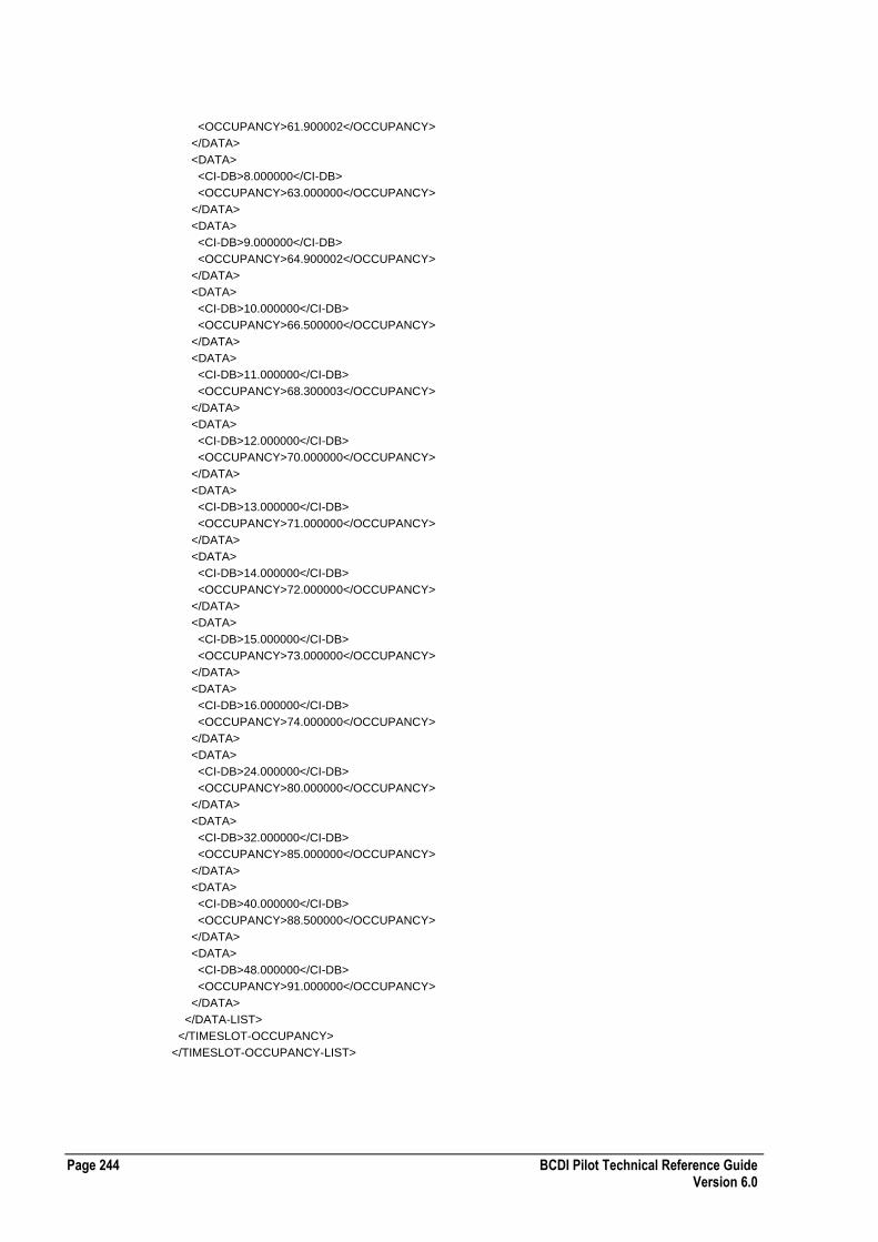
Page 244 BCDI Pilot Technical Reference Guide Version 6.0
<OCCUPANCY>61.900002</OCCUPANCY>
</DATA>
<DATA>
<CI-DB>8.000000</CI-DB>
<OCCUPANCY>63.000000</OCCUPANCY>
</DATA>
<DATA>
<CI-DB>9.000000</CI-DB>
<OCCUPANCY>64.900002</OCCUPANCY>
</DATA>
<DATA>
<CI-DB>10.000000</CI-DB>
<OCCUPANCY>66.500000</OCCUPANCY>
</DATA>
<DATA>
<CI-DB>11.000000</CI-DB>
<OCCUPANCY>68.300003</OCCUPANCY>
</DATA>
<DATA>
<CI-DB>12.000000</CI-DB>
<OCCUPANCY>70.000000</OCCUPANCY>
</DATA>
<DATA>
<CI-DB>13.000000</CI-DB>
<OCCUPANCY>71.000000</OCCUPANCY>
</DATA>
<DATA>
<CI-DB>14.000000</CI-DB>
<OCCUPANCY>72.000000</OCCUPANCY>
</DATA>
<DATA>
<CI-DB>15.000000</CI-DB>
<OCCUPANCY>73.000000</OCCUPANCY>
</DATA>
<DATA>
<CI-DB>16.000000</CI-DB>
<OCCUPANCY>74.000000</OCCUPANCY>
</DATA>
<DATA>
<CI-DB>24.000000</CI-DB>
<OCCUPANCY>80.000000</OCCUPANCY>
</DATA>
<DATA>
<CI-DB>32.000000</CI-DB>
<OCCUPANCY>85.000000</OCCUPANCY>
</DATA>
<DATA>
<CI-DB>40.000000</CI-DB>
<OCCUPANCY>88.500000</OCCUPANCY>
</DATA>
<DATA>
<CI-DB>48.000000</CI-DB>
<OCCUPANCY>91.000000</OCCUPANCY>
</DATA>
</DATA-LIST>
</TIMESLOT-OCCUPANCY>
</TIMESLOT-OCCUPANCY-LIST>
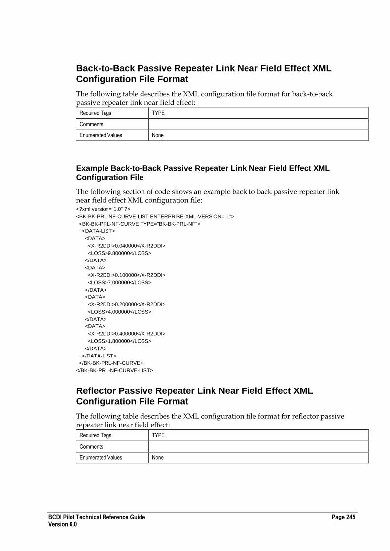
BCDI Pilot Technical Reference Guide Page 245 Version 6.0
Back-to-Back Passive Repeater Link Near Field Effect XML Configuration File Format
The following table describes the XML configuration file format for back-to-back passive repeater link near field effect:
Required Tags TYPE
Comments
Enumerated Values None
Example Back-to-Back Passive Repeater Link Near Field Effect XML Configuration File
The following section of code shows an example back to back passive repeater link near field effect XML configuration file: <?xml version="1.0" ?>
<BK-BK-PRL-NF-CURVE-LIST ENTERPRISE-XML-VERSION="1">
<BK-BK-PRL-NF-CURVE TYPE="BK-BK-PRL-NF">
<DATA-LIST>
<DATA>
<X-R2DDI>0.040000</X-R2DDI>
<LOSS>9.800000</LOSS>
</DATA>
<DATA>
<X-R2DDI>0.100000</X-R2DDI>
<LOSS>7.000000</LOSS>
</DATA>
<DATA>
<X-R2DDI>0.200000</X-R2DDI>
<LOSS>4.000000</LOSS>
</DATA>
<DATA>
<X-R2DDI>0.400000</X-R2DDI>
<LOSS>1.800000</LOSS>
</DATA>
</DATA-LIST>
</BK-BK-PRL-NF-CURVE>
</BK-BK-PRL-NF-CURVE-LIST>
Reflector Passive Repeater Link Near Field Effect XML Configuration File Format
The following table describes the XML configuration file format for reflector passive repeater link near field effect:
Required Tags TYPE
Comments
Enumerated Values None

Page 246 BCDI Pilot Technical Reference Guide Version 6.0
Example Reflector Passive Repeater Link Near Field Effect XML Configuration File
The following section of code shows an example reflector passive repeater link near field effect XML configuration file: <?xml version="1.0" ?>
<RFL-PRL-NF-CURVE-LIST ENTERPRISE-XML-VERSION="1">
<RFL-PRL-NF-CURVE TYPE="RFL-PRL-NF">
<DATA-LIST>
<DATA>
<ONE-K-SZ>0.100000</ONE-K-SZ>
<ETA-1-4>-3.800000</ETA-1-4>
<ETA-1-2>-1.900000</ETA-1-2>
<ETA-1-0>-0.600000</ETA-1-0>
<ETA-0-8>0.400000</ETA-0-8>
<ETA-0-6>0.700000</ETA-0-6>
<ETA-0-4>-0.400000</ETA-0-4>
<ETA-0-2>0.000000</ETA-0-2>
<ETA-0-002>0.000000</ETA-0-002>
</DATA>
<DATA>
<ONE-K-SZ>0.200000</ONE-K-SZ>
<ETA-1-4>-3.800000</ETA-1-4>
<ETA-1-2>-2.300000</ETA-1-2>
<ETA-1-0>-0.900000</ETA-1-0>
<ETA-0-8>0.300000</ETA-0-8>
<ETA-0-6>0.400000</ETA-0-6>
<ETA-0-4>1.900000</ETA-0-4>
<ETA-0-2>3.600000</ETA-0-2>
<ETA-0-002>4.700000</ETA-0-002>
</DATA>
<DATA>
<ONE-K-SZ>0.300000</ONE-K-SZ>
<ETA-1-4>-4.000000</ETA-1-4>
<ETA-1-2>-2.600000</ETA-1-2>
<ETA-1-0>-1.200000</ETA-1-0>
<ETA-0-8>0.000000</ETA-0-8>
<ETA-0-6>1.800000</ETA-0-6>
<ETA-0-4>3.800000</ETA-0-4>
<ETA-0-2>5.300000</ETA-0-2>
<ETA-0-002>6.000000</ETA-0-002>
</DATA>
<DATA>
<ONE-K-SZ>0.400000</ONE-K-SZ>
<ETA-1-4>-4.200000</ETA-1-4>
<ETA-1-2>-3.000000</ETA-1-2>
<ETA-1-0>-0.600000</ETA-1-0>
<ETA-0-8>0.200000</ETA-0-8>
<ETA-0-6>1.900000</ETA-0-6>
<ETA-0-4>3.300000</ETA-0-4>
<ETA-0-2>4.200000</ETA-0-2>
<ETA-0-002>4.800000</ETA-0-002>
</DATA>
<DATA>
<ONE-K-SZ>0.500000</ONE-K-SZ>
<ETA-1-4>-4.500000</ETA-1-4>
<ETA-1-2>-3.200000</ETA-1-2>
<ETA-1-0>-1.600000</ETA-1-0>
<ETA-0-8>0.000000</ETA-0-8>

BCDI Pilot Technical Reference Guide Page 247 Version 6.0
<ETA-0-6>1.400000</ETA-0-6>
<ETA-0-4>2.300000</ETA-0-4>
<ETA-0-2>3.000000</ETA-0-2>
<ETA-0-002>3.400000</ETA-0-002>
</DATA>
<DATA>
<ONE-K-SZ>0.600000</ONE-K-SZ>
<ETA-1-4>-4.600000</ETA-1-4>
<ETA-1-2>-4.800000</ETA-1-2>
<ETA-1-0>-0.500000</ETA-1-0>
<ETA-0-8>0.600000</ETA-0-8>
<ETA-0-6>1.200000</ETA-0-6>
<ETA-0-4>1.800000</ETA-0-4>
<ETA-0-2>2.100000</ETA-0-2>
<ETA-0-002>0.000000</ETA-0-002>
</DATA>
<DATA>
<ONE-K-SZ>0.700000</ONE-K-SZ>
<ETA-1-4>-4.600000</ETA-1-4>
<ETA-1-2>-3.300000</ETA-1-2>
<ETA-1-0>-2.000000</ETA-1-0>
<ETA-0-8>-1.100000</ETA-0-8>
<ETA-0-6>-0.300000</ETA-0-6>
<ETA-0-4>0.200000</ETA-0-4>
<ETA-0-2>0.700000</ETA-0-2>
<ETA-0-002>0.800000</ETA-0-002>
</DATA>
<DATA>
<ONE-K-SZ>0.800000</ONE-K-SZ>
<ETA-1-4>-4.700000</ETA-1-4>
<ETA-1-2>-3.600000</ETA-1-2>
<ETA-1-0>-2.700000</ETA-1-0>
<ETA-0-8>-1.800000</ETA-0-8>
<ETA-0-6>-1.100000</ETA-0-6>
<ETA-0-4>-0.700000</ETA-0-4>
<ETA-0-2>-0.300000</ETA-0-2>
<ETA-0-002>-0.200000</ETA-0-002>
</DATA>
<DATA>
<ONE-K-SZ>1.000000</ONE-K-SZ>
<ETA-1-4>-5.200000</ETA-1-4>
<ETA-1-2>-4.300000</ETA-1-2>
<ETA-1-0>-3.600000</ETA-1-0>
<ETA-0-8>-3.100000</ETA-0-8>
<ETA-0-6>-2.700000</ETA-0-6>
<ETA-0-4>-2.300000</ETA-0-4>
<ETA-0-2>-2.000000</ETA-0-2>
<ETA-0-002>-2.000000</ETA-0-002>
</DATA>
<DATA>
<ONE-K-SZ>1.500000</ONE-K-SZ>
<ETA-1-4>-7.200000</ETA-1-4>
<ETA-1-2>-6.600000</ETA-1-2>
<ETA-1-0>-6.100000</ETA-1-0>
<ETA-0-8>-6.000000</ETA-0-8>
<ETA-0-6>-6.900000</ETA-0-6>
<ETA-0-4>-6.900000</ETA-0-4>
<ETA-0-2>-6.800000</ETA-0-2>
<ETA-0-002>-6.800000</ETA-0-002>
</DATA>
<DATA>

Page 248 BCDI Pilot Technical Reference Guide Version 6.0
<ONE-K-SZ>2.000000</ONE-K-SZ>
<ETA-1-4>-9.000000</ETA-1-4>
<ETA-1-2>-8.500000</ETA-1-2>
<ETA-1-0>-8.500000</ETA-1-0>
<ETA-0-8>-8.500000</ETA-0-8>
<ETA-0-6>-8.500000</ETA-0-6>
<ETA-0-4>-8.500000</ETA-0-4>
<ETA-0-2>-8.500000</ETA-0-2>
<ETA-0-002>-8.500000</ETA-0-002>
</DATA>
<DATA>
<ONE-K-SZ>2.500000</ONE-K-SZ>
<ETA-1-4>-10.500000</ETA-1-4>
<ETA-1-2>-10.500000</ETA-1-2>
<ETA-1-0>-10.500000</ETA-1-0>
<ETA-0-8>-10.500000</ETA-0-8>
<ETA-0-6>-10.500000</ETA-0-6>
<ETA-0-4>-10.500000</ETA-0-4>
<ETA-0-2>-10.500000</ETA-0-2>
<ETA-0-002>-10.500000</ETA-0-002>
</DATA>
</DATA-LIST>
</RFL-PRL-NF-CURVE>
</RFL-PRL-NF-CURVE-LIST>
HSDPA Coding Rates XML Configuration File Format
The following table describes the XML configuration file format for HSDPA coding rates:
Required Tags ID attribute
Comments
Enumerated Values MODULATION
RATE
Example HSDPA Coding Rates XML Configuration File
The following section of code shows an example HSDPA Coding Rates configuration file: <?xml version="1.0" ?>
<HSDPA-LIST ENTERPRISE-XML-VERSION="1">
<HSDPA ID="16QAM 1/2" MODULATION="1" RATE="0.5">
<SECURITY-RO>
<OWNER>admin</OWNER>
<GROUP>All</GROUP>
<CREATED>admin</CREATED>
<MODIFIED>admin</MODIFIED>
</SECURITY-RO>
</HSDPA>
<HSDPA ID="16QAM 1/3" MODULATION="1" RATE="0.33">
<SECURITY-RO>
<OWNER>admin</OWNER>
<GROUP>All</GROUP>
<CREATED>admin</CREATED>
<MODIFIED>admin</MODIFIED>
</SECURITY-RO>
</HSDPA>
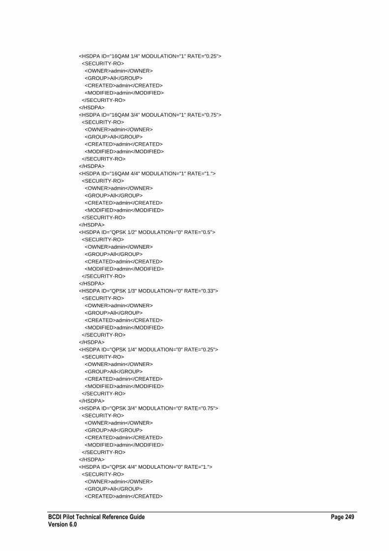
BCDI Pilot Technical Reference Guide Page 249 Version 6.0
<HSDPA ID="16QAM 1/4" MODULATION="1" RATE="0.25">
<SECURITY-RO>
<OWNER>admin</OWNER>
<GROUP>All</GROUP>
<CREATED>admin</CREATED>
<MODIFIED>admin</MODIFIED>
</SECURITY-RO>
</HSDPA>
<HSDPA ID="16QAM 3/4" MODULATION="1" RATE="0.75">
<SECURITY-RO>
<OWNER>admin</OWNER>
<GROUP>All</GROUP>
<CREATED>admin</CREATED>
<MODIFIED>admin</MODIFIED>
</SECURITY-RO>
</HSDPA>
<HSDPA ID="16QAM 4/4" MODULATION="1" RATE="1.">
<SECURITY-RO>
<OWNER>admin</OWNER>
<GROUP>All</GROUP>
<CREATED>admin</CREATED>
<MODIFIED>admin</MODIFIED>
</SECURITY-RO>
</HSDPA>
<HSDPA ID="QPSK 1/2" MODULATION="0" RATE="0.5">
<SECURITY-RO>
<OWNER>admin</OWNER>
<GROUP>All</GROUP>
<CREATED>admin</CREATED>
<MODIFIED>admin</MODIFIED>
</SECURITY-RO>
</HSDPA>
<HSDPA ID="QPSK 1/3" MODULATION="0" RATE="0.33">
<SECURITY-RO>
<OWNER>admin</OWNER>
<GROUP>All</GROUP>
<CREATED>admin</CREATED>
<MODIFIED>admin</MODIFIED>
</SECURITY-RO>
</HSDPA>
<HSDPA ID="QPSK 1/4" MODULATION="0" RATE="0.25">
<SECURITY-RO>
<OWNER>admin</OWNER>
<GROUP>All</GROUP>
<CREATED>admin</CREATED>
<MODIFIED>admin</MODIFIED>
</SECURITY-RO>
</HSDPA>
<HSDPA ID="QPSK 3/4" MODULATION="0" RATE="0.75">
<SECURITY-RO>
<OWNER>admin</OWNER>
<GROUP>All</GROUP>
<CREATED>admin</CREATED>
<MODIFIED>admin</MODIFIED>
</SECURITY-RO>
</HSDPA>
<HSDPA ID="QPSK 4/4" MODULATION="0" RATE="1.">
<SECURITY-RO>
<OWNER>admin</OWNER>
<GROUP>All</GROUP>
<CREATED>admin</CREATED>
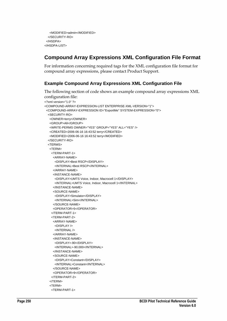
Page 250 BCDI Pilot Technical Reference Guide Version 6.0
<MODIFIED>admin</MODIFIED>
</SECURITY-RO>
</HSDPA>
</HSDPA-LIST>
Compound Array Expressions XML Configuration File Format
For information concerning required tags for the XML configuration file format for compound array expressions, please contact Product Support.
Example Compound Array Expressions XML Configuration File
The following section of code shows an example compound array expressions XML configuration file: <?xml version="1.0" ?>
<COMPOUND-ARRAY-EXPRESSION-LIST ENTERPRISE-XML-VERSION="1">
<COMPOUND-ARRAY-EXPRESSION ID="ExportMe" SYSTEM-EXPRESSION="0">
<SECURITY-RO>
<OWNER>terry</OWNER>
<GROUP>All</GROUP>
<WRITE-PERMS OWNER="YES" GROUP="YES" ALL="YES" />
<CREATED>2006-06-16 16:43:52 terry</CREATED>
<MODIFIED>2006-06-16 16:43:52 terry</MODIFIED>
</SECURITY-RO>
<TERMS>
<TERM>
<TERM-PART-1>
<ARRAY-NAME>
<DISPLAY>Best RSCP</DISPLAY>
<INTERNAL>Best RSCP</INTERNAL>
</ARRAY-NAME>
<INSTANCE-NAME>
<DISPLAY>UMTS Voice, Indoor, Macrocell 1</DISPLAY>
<INTERNAL>UMTS Voice, Indoor, Macrocell 1</INTERNAL>
</INSTANCE-NAME>
<SOURCE-NAME>
<DISPLAY>Simulator</DISPLAY>
<INTERNAL>Sim</INTERNAL>
</SOURCE-NAME>
<OPERATOR>5</OPERATOR>
</TERM-PART-1>
<TERM-PART-2>
<ARRAY-NAME>
<DISPLAY />
<INTERNAL />
</ARRAY-NAME>
<INSTANCE-NAME>
<DISPLAY>-90</DISPLAY>
<INTERNAL>-90.000</INTERNAL>
</INSTANCE-NAME>
<SOURCE-NAME>
<DISPLAY>Constant</DISPLAY>
<INTERNAL>Constant</INTERNAL>
</SOURCE-NAME>
<OPERATOR>9</OPERATOR>
</TERM-PART-2>
</TERM>
<TERM>
<TERM-PART-1>

BCDI Pilot Technical Reference Guide Page 251 Version 6.0
<ARRAY-NAME>
<DISPLAY>Pilot Ec/Io</DISPLAY>
<INTERNAL>FSM Pilot Ec/Io</INTERNAL>
</ARRAY-NAME>
<INSTANCE-NAME>
<DISPLAY>UMTS Voice, Indoor, Macrocell 1</DISPLAY>
<INTERNAL>UMTS Voice, Indoor, Macrocell 1</INTERNAL>
</INSTANCE-NAME>
<SOURCE-NAME>
<DISPLAY>Simulator</DISPLAY>
<INTERNAL>Sim</INTERNAL>
</SOURCE-NAME>
<OPERATOR>5</OPERATOR>
</TERM-PART-1>
<TERM-PART-2>
<ARRAY-NAME>
<DISPLAY />
<INTERNAL />
</ARRAY-NAME>
<INSTANCE-NAME>
<DISPLAY>-15</DISPLAY>
<INTERNAL>-15.000</INTERNAL>
</INSTANCE-NAME>
<SOURCE-NAME>
<DISPLAY>Constant</DISPLAY>
<INTERNAL>Constant</INTERNAL>
</SOURCE-NAME>
<OPERATOR>12</OPERATOR>
</TERM-PART-2>
</TERM>
</TERMS>
<LOGICAL-OUTPUT>
<LOGICAL-OUTPUT-PART-1>
<ARRAY-NAME>
<DISPLAY>Best RSCP</DISPLAY>
<INTERNAL>Best RSCP</INTERNAL>
</ARRAY-NAME>
<INSTANCE-NAME>
<DISPLAY>UMTS Voice, Indoor, Macrocell 1</DISPLAY>
<INTERNAL>UMTS Voice, Indoor, Macrocell 1</INTERNAL>
</INSTANCE-NAME>
<SOURCE-NAME>
<DISPLAY>Simulator</DISPLAY>
<INTERNAL>Sim</INTERNAL>
</SOURCE-NAME>
</LOGICAL-OUTPUT-PART-1>
<LOGICAL-OUTPUT-PART-2>
<ARRAY-NAME>
<DISPLAY />
<INTERNAL />
</ARRAY-NAME>
<INSTANCE-NAME>
<DISPLAY />
<INTERNAL />
</INSTANCE-NAME>
<SOURCE-NAME>
<DISPLAY>No Value</DISPLAY>
<INTERNAL>NoValue</INTERNAL>
</SOURCE-NAME>
</LOGICAL-OUTPUT-PART-2>
</LOGICAL-OUTPUT>
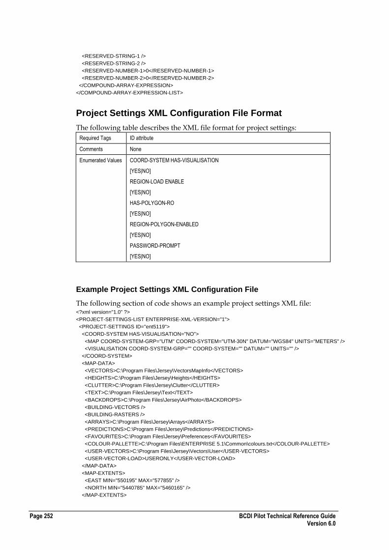
Page 252 BCDI Pilot Technical Reference Guide Version 6.0
<RESERVED-STRING-1 />
<RESERVED-STRING-2 />
<RESERVED-NUMBER-1>0</RESERVED-NUMBER-1>
<RESERVED-NUMBER-2>0</RESERVED-NUMBER-2>
</COMPOUND-ARRAY-EXPRESSION>
</COMPOUND-ARRAY-EXPRESSION-LIST>
Project Settings XML Configuration File Format
The following table describes the XML file format for project settings:
Required Tags ID attribute
Comments None
Enumerated Values COORD-SYSTEM HAS-VISUALISATION
[YES|NO]
REGION-LOAD ENABLE
[YES|NO]
HAS-POLYGON-RO
[YES|NO]
REGION-POLYGON-ENABLED
[YES|NO]
PASSWORD-PROMPT
[YES|NO]
Example Project Settings XML Configuration File
The following section of code shows an example project settings XML file: <?xml version="1.0" ?>
<PROJECT-SETTINGS-LIST ENTERPRISE-XML-VERSION="1">
<PROJECT-SETTINGS ID="ent5119">
<COORD-SYSTEM HAS-VISUALISATION="NO">
<MAP COORD-SYSTEM-GRP="UTM" COORD-SYSTEM="UTM-30N" DATUM="WGS84" UNITS="METERS" />
<VISUALISATION COORD-SYSTEM-GRP="" COORD-SYSTEM="" DATUM="" UNITS="" />
</COORD-SYSTEM>
<MAP-DATA>
<VECTORS>C:\Program Files\Jersey\VectorsMapInfo</VECTORS>
<HEIGHTS>C:\Program Files\Jersey\Heights</HEIGHTS>
<CLUTTER>C:\Program Files\Jersey\Clutter</CLUTTER>
<TEXT>C:\Program Files\Jersey\Text</TEXT>
<BACKDROPS>C:\Program Files\Jersey\AirPhoto</BACKDROPS>
<BUILDING-VECTORS />
<BUILDING-RASTERS />
<ARRAYS>C:\Program Files\Jersey\Arrays</ARRAYS>
<PREDICTIONS>C:\Program Files\Jersey\Predictions</PREDICTIONS>
<FAVOURITES>C:\Program Files\Jersey\Preferences</FAVOURITES>
<COLOUR-PALLETTE>C:\Program Files\ENTERPRISE 5.1\Common\colours.txt</COLOUR-PALLETTE>
<USER-VECTORS>C:\Program Files\Jersey\Vectors\User</USER-VECTORS>
<USER-VECTOR-LOAD>USERONLY</USER-VECTOR-LOAD>
</MAP-DATA>
<MAP-EXTENTS>
<EAST MIN="550195" MAX="577855" />
<NORTH MIN="5440785" MAX="5460165" />
</MAP-EXTENTS>

BCDI Pilot Technical Reference Guide Page 253 Version 6.0
<REGION-LOAD ENABLE="NO">
<LONGITUDE MIN="-180.000000" MAX="180.000000" />
<LATITUDE MIN="-89.000000" MAX="89.999999" />
</REGION-LOAD>
<INFO>
<CREATED>2005-11-07 12:34:53</CREATED>
<MODIFIED>2005-11-07 14:56:19</MODIFIED>
<DESCRIPTION />
<COMMENTS />
</INFO>
<DISTRIBUTED-SIM>
<FOLDER-PATH />
<PASSWORD-PROMPT>YES</PASSWORD-PROMPT>
</DISTRIBUTED-SIM>
<OPTIMA-LOGIN>
<DATA-SOURCE />
<USER />
<PASSWORD />
</OPTIMA-LOGIN>
<TARGET-MASTER-FILE />
</PROJECT-SETTINGS>
</PROJECT-SETTINGS-LIST
XML ADVANTAGE File Formats
This section describes the ADVANTAGE file formats for XML.
ADVANTAGE Plans XML File Format
The following table describes the XML file format for ADVANTAGE Plans:
Required Tags ID attribute
Comments

Page 254 BCDI Pilot Technical Reference Guide Version 6.0
Enumerated Values ElectricalBeamAdjust
[Onsite |
Supports
[GSM | UMTS
HSDPASupport
[true | false]
IsMAList
[true | false]
PowerEquipFixed
[true | false]
PatternFixed
[true | false]
TotalTiltFixed
[true | false]
HeightFixed
[true | false]
AzimuthFixed
[true | false]
BearingsLimited
[true | false]
DeviceFixed
[true | false]
MechanicalTiltFixed
[true | false]
ConstraintType
[UniformAngle | Uniform | DeltaOrSet | Set]
UseDelta
[true | false]
Type
[OutputPower | HSDPALink
PccpchEnabled
[true | false]
PschEnabled
[true | false]
SccpchEnabled
[true | false]
SschEnabled
[true | false]
AichEnabled
[true | false]
PichEnabled
[true | false]
HsdpaSupported
[true | false]
VariableID
[Azimuth | HSDPALink]
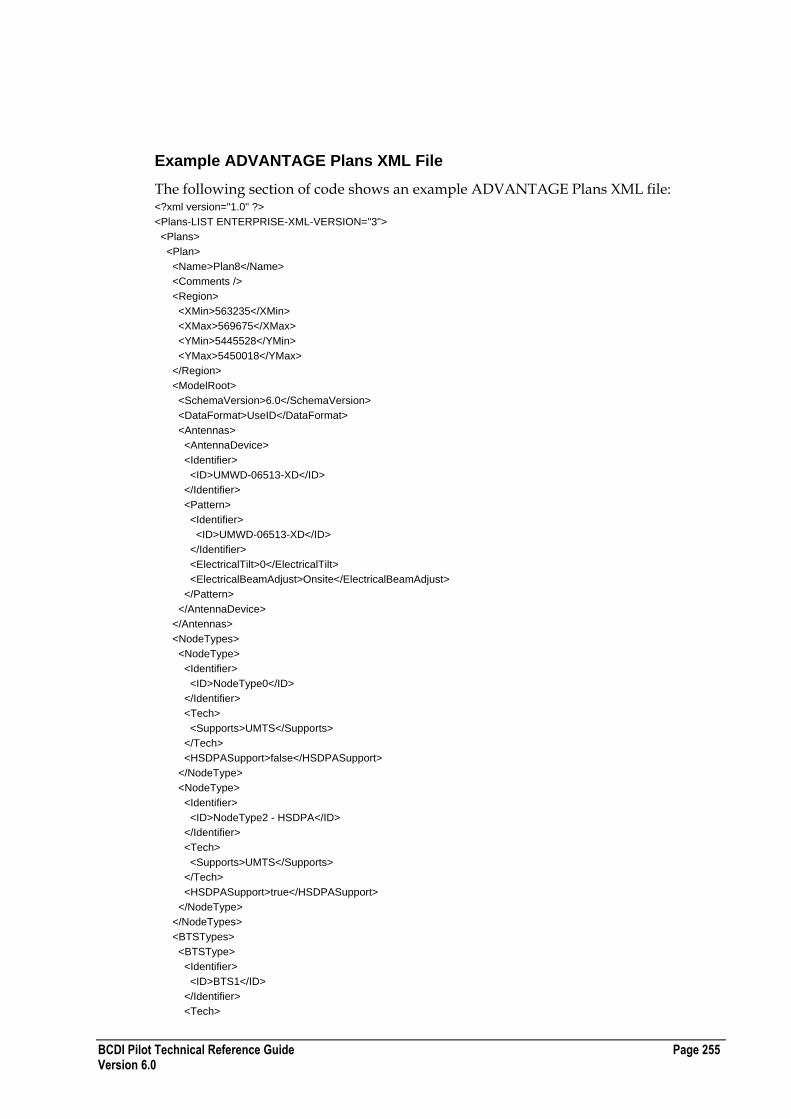
BCDI Pilot Technical Reference Guide Page 255 Version 6.0
Example ADVANTAGE Plans XML File
The following section of code shows an example ADVANTAGE Plans XML file: <?xml version="1.0" ?>
<Plans-LIST ENTERPRISE-XML-VERSION="3">
<Plans>
<Plan>
<Name>Plan8</Name>
<Comments />
<Region>
<XMin>563235</XMin>
<XMax>569675</XMax>
<YMin>5445528</YMin>
<YMax>5450018</YMax>
</Region>
<ModelRoot>
<SchemaVersion>6.0</SchemaVersion>
<DataFormat>UseID</DataFormat>
<Antennas>
<AntennaDevice>
<Identifier>
<ID>UMWD-06513-XD</ID>
</Identifier>
<Pattern>
<Identifier>
<ID>UMWD-06513-XD</ID>
</Identifier>
<ElectricalTilt>0</ElectricalTilt>
<ElectricalBeamAdjust>Onsite</ElectricalBeamAdjust>
</Pattern>
</AntennaDevice>
</Antennas>
<NodeTypes>
<NodeType>
<Identifier>
<ID>NodeType0</ID>
</Identifier>
<Tech>
<Supports>UMTS</Supports>
</Tech>
<HSDPASupport>false</HSDPASupport>
</NodeType>
<NodeType>
<Identifier>
<ID>NodeType2 - HSDPA</ID>
</Identifier>
<Tech>
<Supports>UMTS</Supports>
</Tech>
<HSDPASupport>true</HSDPASupport>
</NodeType>
</NodeTypes>
<BTSTypes>
<BTSType>
<Identifier>
<ID>BTS1</ID>
</Identifier>
<Tech>

Page 256 BCDI Pilot Technical Reference Guide Version 6.0
<Supports>GSM</Supports>
</Tech>
<MinOutputPower>0</MinOutputPower>
<MaxOutputPower>100</MaxOutputPower>
</BTSType>
<BTSType>
<Identifier>
<ID>BTS2</ID>
</Identifier>
<Tech>
<Supports>GSM</Supports>
</Tech>
<MinOutputPower>0</MinOutputPower>
<MaxOutputPower>100</MaxOutputPower>
</BTSType>
<BTSType>
<Identifier>
<ID>BTS0</ID>
</Identifier>
<Tech>
<Supports>GSM</Supports>
</Tech>
<MinOutputPower>0</MinOutputPower>
<MaxOutputPower>100</MaxOutputPower>
</BTSType>
</BTSTypes>
<ThreeGCarriers>
<Carrier>
<Identifier>
<ID>Carrier1</ID>
</Identifier>
<Tech>
<Supports>UMTS</Supports>
</Tech>
</Carrier>
<Carrier>
<Identifier>
<ID>Carrier2</ID>
</Identifier>
<Tech>
<Supports>UMTS</Supports>
</Tech>
</Carrier>
<Carrier>
<Identifier>
<ID>Carrier3</ID>
</Identifier>
<Tech>
<Supports>UMTS</Supports>
</Tech>
</Carrier>
<Carrier>
<Identifier>
<ID>Carrier4</ID>
</Identifier>
<Tech>
<Supports>UMTS</Supports>
</Tech>
</Carrier>
<TwoGCarriers>
<Carrier>

BCDI Pilot Technical Reference Guide Page 257 Version 6.0
<Identifier>
<ID>Carrier 1</ID>
</Identifier>
<Tech>
<Supports>GSM</Supports>
</Tech>
</Carrier>
<Carrier>
<Identifier>
<ID>Carrier 2</ID>
</Identifier>
<Tech>
<Supports>GSM</Supports>
</Tech>
</Carrier>
<Carrier>
<Identifier>
<ID>Carrier 3</ID>
</Identifier>
<Tech>
<Supports>GSM</Supports>
</Tech>
</Carrier>
<CarrierLayers>
<CarrierLayer>
<Identifier>
<ID>DVC</ID>
</Identifier>
<MaxAllocatable>1</MaxAllocatable>
<IsMAList>false</IsMAList>
<Carriers />
</CarrierLayer>
<CarrierLayer>
<Identifier>
<ID>DCCH</ID>
</Identifier>
<MaxAllocatable>1</MaxAllocatable>
<IsMAList>false</IsMAList>
<Carriers />
</CarrierLayer>
<CarrierLayer>
<Identifier>
<ID>Hopping (Range): so MA unticked</ID>
</Identifier>
<MaxAllocatable>12</MaxAllocatable>
<IsMAList>false</IsMAList>
<Carriers>
<Carrier>
<Identifier>
<ID>Carrier 1</ID>
</Identifier>
</Carrier>
<Carrier>
<Identifier>
<ID>Carrier 2</ID>
</Identifier>
</Carrier>
<Carrier>
<Identifier>
<ID>Carrier 3</ID>
</Identifier>
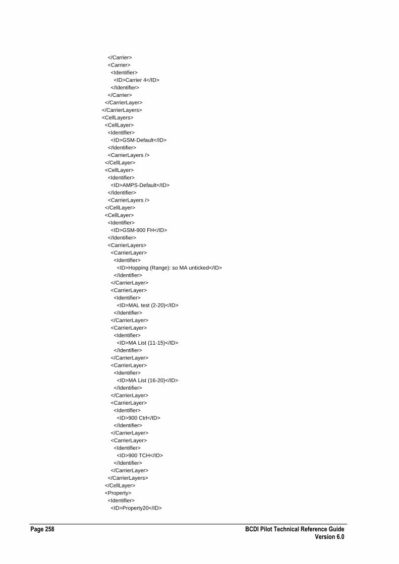
Page 258 BCDI Pilot Technical Reference Guide Version 6.0
</Carrier>
<Carrier>
<Identifier>
<ID>Carrier 4</ID>
</Identifier>
</Carrier>
</CarrierLayer>
</CarrierLayers>
<CellLayers>
<CellLayer>
<Identifier>
<ID>GSM-Default</ID>
</Identifier>
<CarrierLayers />
</CellLayer>
<CellLayer>
<Identifier>
<ID>AMPS-Default</ID>
</Identifier>
<CarrierLayers />
</CellLayer>
<CellLayer>
<Identifier>
<ID>GSM-900 FH</ID>
</Identifier>
<CarrierLayers>
<CarrierLayer>
<Identifier>
<ID>Hopping (Range): so MA unticked</ID>
</Identifier>
</CarrierLayer>
<CarrierLayer>
<Identifier>
<ID>MAL test (2-20)</ID>
</Identifier>
</CarrierLayer>
<CarrierLayer>
<Identifier>
<ID>MA List (11-15)</ID>
</Identifier>
</CarrierLayer>
<CarrierLayer>
<Identifier>
<ID>MA List (16-20)</ID>
</Identifier>
</CarrierLayer>
<CarrierLayer>
<Identifier>
<ID>900 Ctrl</ID>
</Identifier>
</CarrierLayer>
<CarrierLayer>
<Identifier>
<ID>900 TCH</ID>
</Identifier>
</CarrierLayer>
</CarrierLayers>
</CellLayer>
<Property>
<Identifier>
<ID>Property20</ID>
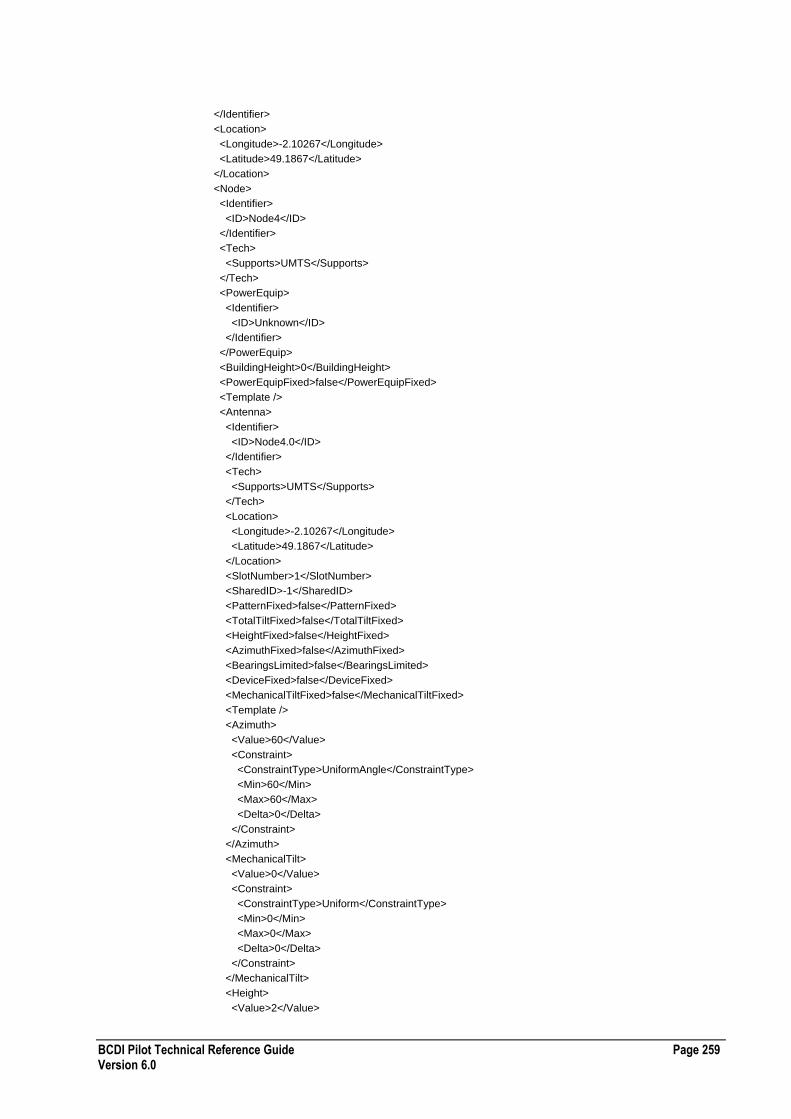
BCDI Pilot Technical Reference Guide Page 259 Version 6.0
</Identifier>
<Location>
<Longitude>-2.10267</Longitude>
<Latitude>49.1867</Latitude>
</Location>
<Node>
<Identifier>
<ID>Node4</ID>
</Identifier>
<Tech>
<Supports>UMTS</Supports>
</Tech>
<PowerEquip>
<Identifier>
<ID>Unknown</ID>
</Identifier>
</PowerEquip>
<BuildingHeight>0</BuildingHeight>
<PowerEquipFixed>false</PowerEquipFixed>
<Template />
<Antenna>
<Identifier>
<ID>Node4.0</ID>
</Identifier>
<Tech>
<Supports>UMTS</Supports>
</Tech>
<Location>
<Longitude>-2.10267</Longitude>
<Latitude>49.1867</Latitude>
</Location>
<SlotNumber>1</SlotNumber>
<SharedID>-1</SharedID>
<PatternFixed>false</PatternFixed>
<TotalTiltFixed>false</TotalTiltFixed>
<HeightFixed>false</HeightFixed>
<AzimuthFixed>false</AzimuthFixed>
<BearingsLimited>false</BearingsLimited>
<DeviceFixed>false</DeviceFixed>
<MechanicalTiltFixed>false</MechanicalTiltFixed>
<Template />
<Azimuth>
<Value>60</Value>
<Constraint>
<ConstraintType>UniformAngle</ConstraintType>
<Min>60</Min>
<Max>60</Max>
<Delta>0</Delta>
</Constraint>
</Azimuth>
<MechanicalTilt>
<Value>0</Value>
<Constraint>
<ConstraintType>Uniform</ConstraintType>
<Min>0</Min>
<Max>0</Max>
<Delta>0</Delta>
</Constraint>
</MechanicalTilt>
<Height>
<Value>2</Value>

Page 260 BCDI Pilot Technical Reference Guide Version 6.0
<Constraint>
<ConstraintType>DeltaOrSet</ConstraintType>
<UseDelta>true</UseDelta>
<Constraint1>
<ConstraintType>Uniform</ConstraintType>
<Min>2</Min>
<Max>2</Max>
<Delta>0</Delta>
</Constraint1>
<Constraint2>
<ConstraintType>Set</ConstraintType>
<Possibles />
</Constraint2>
</Constraint>
</Height>
<MaxTilt>0</MaxTilt>
<AntennaPattern>
<Value>
<Identifier>
<ID>UMWD-06513-XD</ID>
</Identifier>
</Value>
<Possibles />
</AntennaPattern>
<Cells>
<Cell>
<Identifier>
<ID>Node4A</ID>
</Identifier>
</Cell>
</Cells>
</Antenna>
<Cell>
<Identifier>
<ID>Node4A</ID>
</Identifier>
<Tech>
<Supports>UMTS</Supports>
</Tech>
<Neighbours />
<SubCell3G>
<Tech>
<Supports>UMTS</Supports>
</Tech>
<Template />
<Power>
<PowerVal>
<Type>OutputPower</Type>
<Value>43</Value>
<Constraint>
<ConstraintType>Uniform</ConstraintType>
<Min>43</Min>
<Max>43</Max>
<Delta>0</Delta>
</Constraint>
</PowerVal>
<PowerVal>
<Type>HSDPALink</Type>
<Value>30</Value>
<Constraint>
<ConstraintType>Uniform</ConstraintType>

BCDI Pilot Technical Reference Guide Page 261 Version 6.0
<Min>30</Min>
<Max>30</Max>
<Delta>0</Delta>
</Constraint>
</PowerVal>
<ChannelSettings>
<PCCPCH>30</PCCPCH>
<PSCH>30</PSCH>
<SCCPCH>27</SCCPCH>
<SSCH>27</SSCH>
<AICH>-200</AICH>
<PICH>-200</PICH>
<DownLinkTrafficPower>26.6427</DownLinkTrafficPower>
<PCCPCHActivity>0.9</PCCPCHActivity>
<PSCHActivity>0.1</PSCHActivity>
<SccpchActivity>1</SccpchActivity>
<SSCHActivity>0.1</SSCHActivity>
<AichActivity>-200</AichActivity>
<PichActivity>-200</PichActivity>
<PccpchEnabled>true</PccpchEnabled>
<PschEnabled>true</PschEnabled>
<SccpchEnabled>true</SccpchEnabled>
<SschEnabled>true</SschEnabled>
<AichEnabled>false</AichEnabled>
<PichEnabled>false</PichEnabled>
<HsdpaSupported>false</HsdpaSupported>
</ChannelSettings>
</Power>
<CarrierKey>
<Identifier>
<ID>Carrier1</ID>
</Identifier>
</CarrierKey>
<AntennaKeys>
<Identifier>
<ID>Node4.0</ID>
</Identifier>
</AntennaKeys>
</SubCell3G>
</Cell>
<SectorConfigurations>
<Value>
<SubCellKey>Node4A|Carrier1</SubCellKey>
<SubCellKey>Node4B|Carrier1</SubCellKey>
<SubCellKey>Node4C|Carrier1</SubCellKey>
</Value>
<Configuration>
<SubCellKey>Node4A|Carrier1</SubCellKey>
<SubCellKey>Node4B|Carrier1</SubCellKey>
<SubCellKey>Node4C|Carrier1</SubCellKey>
</Configuration>
</SectorConfigurations>
</Node>
</Property>
</ModelRoot>
</Plan>
<DeltaPlan>
<Name>Plan7DeltaPlan0</Name>
<ParentPlan>Plan7</ParentPlan>
<DeltaData>
<SchemaVersion>6.0</SchemaVersion>
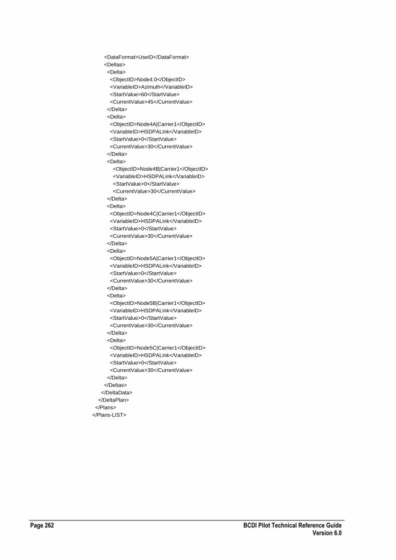
Page 262 BCDI Pilot Technical Reference Guide Version 6.0
<DataFormat>UseID</DataFormat>
<Deltas>
<Delta>
<ObjectID>Node4.0</ObjectID>
<VariableID>Azimuth</VariableID>
<StartValue>60</StartValue>
<CurrentValue>45</CurrentValue>
</Delta>
<Delta>
<ObjectID>Node4A|Carrier1</ObjectID>
<VariableID>HSDPALink</VariableID>
<StartValue>0</StartValue>
<CurrentValue>30</CurrentValue>
</Delta>
<Delta>
<ObjectID>Node4B|Carrier1</ObjectID>
<VariableID>HSDPALink</VariableID>
<StartValue>0</StartValue>
<CurrentValue>30</CurrentValue>
</Delta>
<Delta>
<ObjectID>Node4C|Carrier1</ObjectID>
<VariableID>HSDPALink</VariableID>
<StartValue>0</StartValue>
<CurrentValue>30</CurrentValue>
</Delta>
<Delta>
<ObjectID>Node5A|Carrier1</ObjectID>
<VariableID>HSDPALink</VariableID>
<StartValue>0</StartValue>
<CurrentValue>30</CurrentValue>
</Delta>
<Delta>
<ObjectID>Node5B|Carrier1</ObjectID>
<VariableID>HSDPALink</VariableID>
<StartValue>0</StartValue>
<CurrentValue>30</CurrentValue>
</Delta>
<Delta>
<ObjectID>Node5C|Carrier1</ObjectID>
<VariableID>HSDPALink</VariableID>
<StartValue>0</StartValue>
<CurrentValue>30</CurrentValue>
</Delta>
</Deltas>
</DeltaData>
</DeltaPlan>
</Plans>
</Plans-LIST>

BCDI Pilot Technical Reference Guide Page 263 Version 6.0
ADVANTAGE Details XML File Format
The following table describes the XML file format for ADVANTAGE Details:
Required Tags ID attribute
Comments
Enumerated Values USE-VECTOR-POLYGONS
[0 | 1]
USE-DRIVE-TEST-ROUTES
[0 | 1]
TECHNOLOGY-TYPE
Example ADVANTAGE Details XML File
The following section of code shows an example ADVANTAGE Details XML file: <DETAILS-LIST ENTERPRISE-XML-VERSION="3">
<DETAILS ID="New Config Detail 1 - UMTS Voice">
<ACTIVE />
<COMMENTS />
<RES>50</RES>
<REFERENCE-TERMINAL-TYPE>6160285</REFERENCE-TERMINAL-TYPE>
<TERMINAL-TYPE-LIST>
<TERMINAL-TYPE>UMTS Voice</TERMINAL-TYPE>
</TERMINAL-TYPE-LIST>
<USE-VECTOR-POLYGONS>0</USE-VECTOR-POLYGONS>
<USE-DRIVE-TEST-ROUTES>0</USE-DRIVE-TEST-ROUTES>
<SIM-CONFIG-LIST>
<SIM-CONFIG ID="GSM">
<TECHNOLOGY-TYPE>1</TECHNOLOGY-TYPE>
<MIN-SIGNAL-STRENGTH>-102</MIN-SIGNAL-STRENGTH>
<MAX-SERVERS>10</MAX-SERVERS>
<SNAPSHOTS>1</SNAPSHOTS>
<SA-CONFIG />
<MCS-CONFIG />
<MCS-51-CONFIG>M[`,```(````"`````P```&0`````````````````````````9``````````` M`0```)W_70`````````````````````````!`````````!$```!C.EPS9U]B M86-K=7`N,V=R`````````#Y````````````!!@````8``````,!```````"8 M.@```````````````#_-S$P_```````````!`````````````````````0`` %```````@</MCS-51-CONFIG>
</SIM-CONFIG>
<SIM-CONFIG ID="UMTS">
<TECHNOLOGY-TYPE>2</TECHNOLOGY-TYPE>
<MIN-SIGNAL-STRENGTH>-102</MIN-SIGNAL-STRENGTH>
<MAX-SERVERS>10</MAX-SERVERS>
<SNAPSHOTS>5</SNAPSHOTS>
<SA-CONFIG />
<MCS-CONFIG />
<MCS-51-CONFIG>M[`,```(````"`````P```&0`````````````````````````9``````````` M`0```)W_70`````````````````````````!`````````!$```!C.EPS9U]B M86-K=7`N,V=R`````````#Y````````````!!@````8``````,!```````"8 M.@```````````````#_-S$P_```````````!`````````````````````0`` %```````@</MCS-51-CONFIG>
</SIM-CONFIG>
</SIM-CONFIG-LIST>
</DETAILS>
<DETAILS ID="New Config Detail - city central">
<COMMENTS />
<RES>50</RES>
<REFERENCE-TERMINAL-TYPE>6160285</REFERENCE-TERMINAL-TYPE>

Page 264 BCDI Pilot Technical Reference Guide Version 6.0
<TERMINAL-TYPE-LIST>
<TERMINAL-TYPE>UMTS Voice</TERMINAL-TYPE>
</TERMINAL-TYPE-LIST>
<USE-VECTOR-POLYGONS>1</USE-VECTOR-POLYGONS>
<VECTOR-LIST>
<VECTOR GUID="28E1A109-E46A-4EC3-BF97-90C066ADEBD4" TYPE="1" />
</VECTOR-LIST>
<USE-DRIVE-TEST-ROUTES>0</USE-DRIVE-TEST-ROUTES>
<SIM-CONFIG-LIST>
<SIM-CONFIG ID="GSM">
<TECHNOLOGY-TYPE>1</TECHNOLOGY-TYPE>
<MIN-SIGNAL-STRENGTH>-102</MIN-SIGNAL-STRENGTH>
<MAX-SERVERS>10</MAX-SERVERS>
<SNAPSHOTS>1</SNAPSHOTS>
<SA-CONFIG />
<MCS-CONFIG />
<MCS-51-CONFIG>M[`,```(````"`````P```&0`````````````````````````9``````````` M`0```)W_70`````````````````````````!`````````!$```!C.EPS9U]B M86-K=7`N,V=R`````````#Y````````````!!@````8``````,!```````"8 M.@```````````````#_-S$P_```````````!`````````````````````0`` %```````@</MCS-51-CONFIG>
</SIM-CONFIG>
<SIM-CONFIG ID="UMTS">
<TECHNOLOGY-TYPE>2</TECHNOLOGY-TYPE>
<MIN-SIGNAL-STRENGTH>-102</MIN-SIGNAL-STRENGTH>
<MAX-SERVERS>10</MAX-SERVERS>
<SNAPSHOTS>1</SNAPSHOTS>
<SA-CONFIG />
<MCS-CONFIG />
<MCS-51-CONFIG>M[`,```(````"`````P```&0`````````````````````````9``````````` M`0```)W_70`````````````````````````!`````````!$```!C.EPS9U]B M86-K=7`N,V=R`````````#Y````````````!!@````8``````,!```````"8 M.@```````````````#_-S$P_```````````!`````````````````````0`` %```````@</MCS-51-CONFIG>
</SIM-CONFIG>
</SIM-CONFIG-LIST>
</DETAILS>
<DETAILS ID="New Config Detail6">
<COMMENTS />
<RES>200</RES>
<REFERENCE-TERMINAL-TYPE />
<TERMINAL-TYPE-LIST />
<USE-VECTOR-POLYGONS>0</USE-VECTOR-POLYGONS>
<USE-DRIVE-TEST-ROUTES>0</USE-DRIVE-TEST-ROUTES>
<SIM-CONFIG-LIST>
<SIM-CONFIG ID="GSM">
<TECHNOLOGY-TYPE>1</TECHNOLOGY-TYPE>
<MIN-SIGNAL-STRENGTH>-102</MIN-SIGNAL-STRENGTH>
<MAX-SERVERS>10</MAX-SERVERS>
<SNAPSHOTS>1</SNAPSHOTS>
<SA-CONFIG />
<MCS-CONFIG />
<MCS-51-CONFIG />
</SIM-CONFIG>
<SIM-CONFIG ID="UMTS">
<TECHNOLOGY-TYPE>2</TECHNOLOGY-TYPE>
<MIN-SIGNAL-STRENGTH>-102</MIN-SIGNAL-STRENGTH>
<MAX-SERVERS>10</MAX-SERVERS>
<SNAPSHOTS>1</SNAPSHOTS>
<SA-CONFIG />
<MCS-CONFIG />
<MCS-51-CONFIG />
</SIM-CONFIG>
</SIM-CONFIG-LIST>
</DETAILS>
</DETAILS-LIST>

BCDI Pilot Technical Reference Guide Page 265 Version 6.0
Global Design Targets XML File Format
The following table describes the XML file format for global design targets:
Required Tags ID attribute
Comments An ID of -1 indicates the global design target, while a positive integer indicates an action cost
Enumerated Values None
Example Global Design Targets XML File
The following section of code shows an example global design targets XML file: <?xml version="1.0" ?>
<GLOBAL-DESIGN-TARGET-LIST ENTERPRISE-XML-VERSION="3">
<GLOBAL-DESIGN-TARGET ID="-1">
<XML-LENGTH>684</XML-LENGTH>
<XML-DATA><GLOBAL-DESIGN-TARGETS><BUDGET><MAX-COST VALUE="0" MULTIPLIER="1"/><MAX-RISK VALUE="0" MULTIPLIER="1"/></BUDGET><MANPOWER-1><MAX-COST VALUE="0" MULTIPLIER="1"/><MAX-RISK VALUE="0" MULTIPLIER="1"/></MANPOWER-1><MANPOWER-2><MAX-COST VALUE="0" MULTIPLIER="1"/><MAX-RISK VALUE="0" MULTIPLIER="1"/></MANPOWER-2><MANPOWER-3><MAX-COST VALUE="0" MULTIPLIER="1"/><MAX-RISK VALUE="0" MULTIPLIER="1"/></MANPOWER-3><MANPOWER-4><MAX-COST VALUE="0" MULTIPLIER="1"/><MAX-RISK VALUE="0" MULTIPLIER="1"/></MANPOWER-4><MANPOWER-5><MAX-COST VALUE="0" MULTIPLIER="1"/><MAX-RISK VALUE="0" MULTIPLIER="1"/></MANPOWER-5><PERFORMANCE><MAX-RISK VALUE="0" MULTIPLIER="1"/></PERFORMANCE></GLOBAL-DESIGN-TARGETS></XML-DATA>
</GLOBAL-DESIGN-TARGET>
<GLOBAL-DESIGN-TARGET ID="1">
<XML-LENGTH>438</XML-LENGTH>
<XML-DATA><ACTION-COSTS><AZIMUTH><BUDGET><COST VALUE="0"/><RISK VALUE="0"/></BUDGET><MANPOWER-1><COST VALUE="0"/><RISK VALUE="0"/></MANPOWER-1><MANPOWER-2><COST VALUE="0"/><RISK VALUE="0"/></MANPOWER-2><MANPOWER-3><COST VALUE="0"/><RISK VALUE="0"/></MANPOWER-3><MANPOWER-4><COST VALUE="0"/><RISK VALUE="0"/></MANPOWER-4><MANPOWER-5><COST VALUE="0"/><RISK VALUE="0"/></MANPOWER-5><PERFORMANCE><RISK VALUE="0"/></PERFORMANCE></AZIMUTH></ACTION-COSTS></XML-DATA>
</GLOBAL-DESIGN-TARGET>
<GLOBAL-DESIGN-TARGET ID="2">
<XML-LENGTH>462</XML-LENGTH>
<XML-DATA><ACTION-COSTS><MECHANICAL-DOWNTILT><BUDGET><COST VALUE="0"/><RISK VALUE="0"/></BUDGET><MANPOWER-1><COST VALUE="0"/><RISK VALUE="0"/></MANPOWER-1><MANPOWER-2><COST VALUE="0"/><RISK VALUE="0"/></MANPOWER-2><MANPOWER-3><COST VALUE="0"/><RISK VALUE="0"/></MANPOWER-3><MANPOWER-4><COST VALUE="0"/><RISK VALUE="0"/></MANPOWER-4><MANPOWER-5><COST VALUE="0"/><RISK VALUE="0"/></MANPOWER-5><PERFORMANCE><RISK VALUE="0"/></PERFORMANCE></MECHANICAL-DOWNTILT></ACTION-COSTS></XML-DATA>
</GLOBAL-DESIGN-TARGET>
<GLOBAL-DESIGN-TARGET ID="3">
<XML-LENGTH>436</XML-LENGTH>
<XML-DATA><ACTION-COSTS><HEIGHT><BUDGET><COST VALUE="0"/><RISK VALUE="0"/></BUDGET><MANPOWER-1><COST VALUE="0"/><RISK VALUE="0"/></MANPOWER-1><MANPOWER-2><COST VALUE="0"/><RISK VALUE="0"/></MANPOWER-2><MANPOWER-3><COST VALUE="0"/><RISK VALUE="0"/></MANPOWER-3><MANPOWER-4><COST VALUE="0"/><RISK VALUE="0"/></MANPOWER-4><MANPOWER-5><COST VALUE="0"/><RISK VALUE="0"/></MANPOWER-5><PERFORMANCE><RISK VALUE="0"/></PERFORMANCE></HEIGHT></ACTION-COSTS></XML-DATA>
</GLOBAL-DESIGN-TARGET>
<GLOBAL-DESIGN-TARGET ID="4">
<XML-LENGTH>440</XML-LENGTH>
<XML-DATA><ACTION-COSTS><MASK-RED><BUDGET><COST VALUE="0"/><RISK VALUE="0"/></BUDGET><MANPOWER-1><COST VALUE="0"/><RISK VALUE="0"/></MANPOWER-1><MANPOWER-2><COST VALUE="0"/><RISK VALUE="0"/></MANPOWER-2><MANPOWER-3><COST VALUE="0"/><RISK VALUE="0"/></MANPOWER-3><MANPOWER-4><COST VALUE="0"/><RISK VALUE="0"/></MANPOWER-4><MANPOWER-5><COST VALUE="0"/><RISK VALUE="0"/></MANPOWER-5><PERFORMANCE><RISK VALUE="0"/></PERFORMANCE></MASK-RED></ACTION-COSTS></XML-DATA>
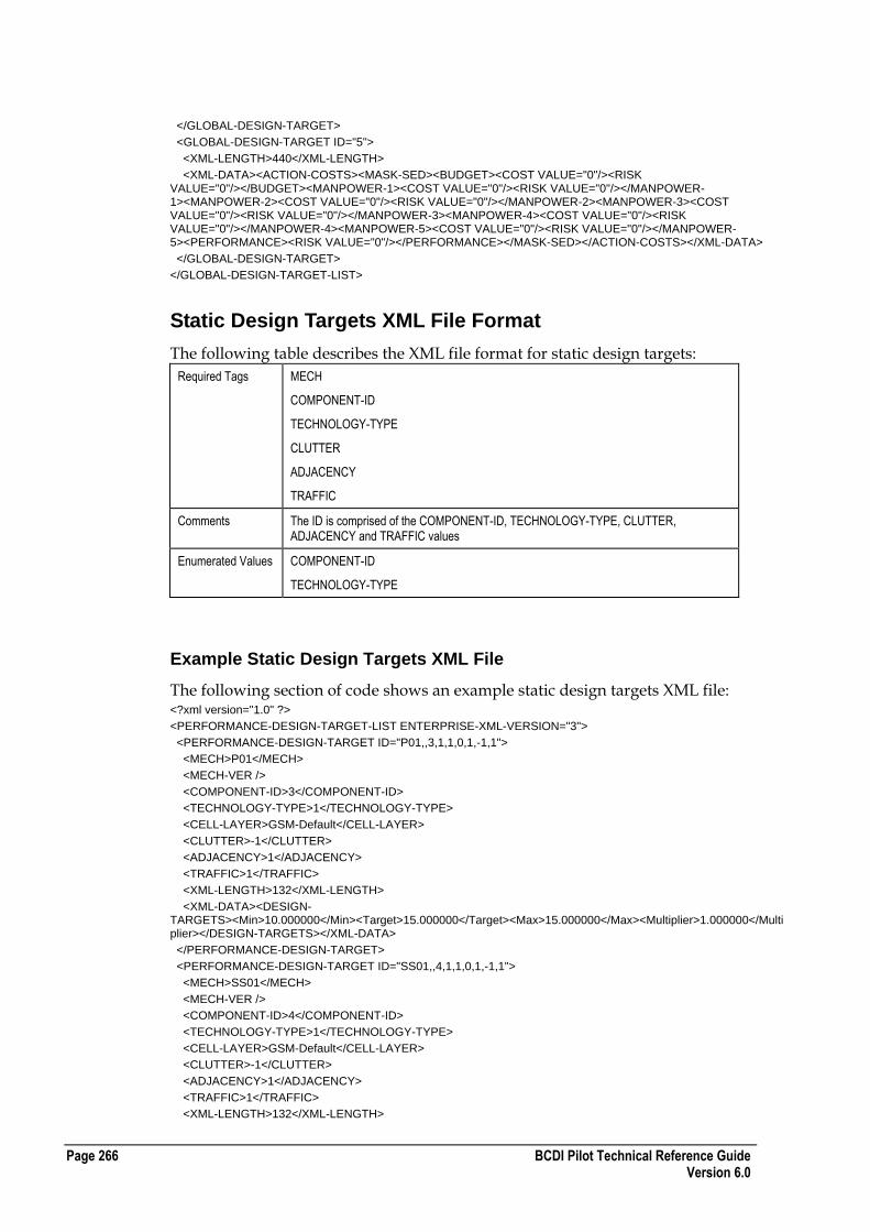
Page 266 BCDI Pilot Technical Reference Guide Version 6.0
</GLOBAL-DESIGN-TARGET>
<GLOBAL-DESIGN-TARGET ID="5">
<XML-LENGTH>440</XML-LENGTH>
<XML-DATA><ACTION-COSTS><MASK-SED><BUDGET><COST VALUE="0"/><RISK VALUE="0"/></BUDGET><MANPOWER-1><COST VALUE="0"/><RISK VALUE="0"/></MANPOWER-1><MANPOWER-2><COST VALUE="0"/><RISK VALUE="0"/></MANPOWER-2><MANPOWER-3><COST VALUE="0"/><RISK VALUE="0"/></MANPOWER-3><MANPOWER-4><COST VALUE="0"/><RISK VALUE="0"/></MANPOWER-4><MANPOWER-5><COST VALUE="0"/><RISK VALUE="0"/></MANPOWER-5><PERFORMANCE><RISK VALUE="0"/></PERFORMANCE></MASK-SED></ACTION-COSTS></XML-DATA>
</GLOBAL-DESIGN-TARGET>
</GLOBAL-DESIGN-TARGET-LIST>
Static Design Targets XML File Format
The following table describes the XML file format for static design targets:
Required Tags MECH
COMPONENT-ID
TECHNOLOGY-TYPE
CLUTTER
ADJACENCY
TRAFFIC
Comments The ID is comprised of the COMPONENT-ID, TECHNOLOGY-TYPE, CLUTTER, ADJACENCY and TRAFFIC values
Enumerated Values COMPONENT-ID
TECHNOLOGY-TYPE
Example Static Design Targets XML File
The following section of code shows an example static design targets XML file: <?xml version="1.0" ?>
<PERFORMANCE-DESIGN-TARGET-LIST ENTERPRISE-XML-VERSION="3">
<PERFORMANCE-DESIGN-TARGET ID="P01,,3,1,1,0,1,-1,1">
<MECH>P01</MECH>
<MECH-VER />
<COMPONENT-ID>3</COMPONENT-ID>
<TECHNOLOGY-TYPE>1</TECHNOLOGY-TYPE>
<CELL-LAYER>GSM-Default</CELL-LAYER>
<CLUTTER>-1</CLUTTER>
<ADJACENCY>1</ADJACENCY>
<TRAFFIC>1</TRAFFIC>
<XML-LENGTH>132</XML-LENGTH>
<XML-DATA><DESIGN-TARGETS><Min>10.000000</Min><Target>15.000000</Target><Max>15.000000</Max><Multiplier>1.000000</Multiplier></DESIGN-TARGETS></XML-DATA>
</PERFORMANCE-DESIGN-TARGET>
<PERFORMANCE-DESIGN-TARGET ID="SS01,,4,1,1,0,1,-1,1">
<MECH>SS01</MECH>
<MECH-VER />
<COMPONENT-ID>4</COMPONENT-ID>
<TECHNOLOGY-TYPE>1</TECHNOLOGY-TYPE>
<CELL-LAYER>GSM-Default</CELL-LAYER>
<CLUTTER>-1</CLUTTER>
<ADJACENCY>1</ADJACENCY>
<TRAFFIC>1</TRAFFIC>
<XML-LENGTH>132</XML-LENGTH>

BCDI Pilot Technical Reference Guide Page 267 Version 6.0
<XML-DATA><DESIGN-TARGETS><Min>10.000000</Min><Target>20.000000</Target><Max>20.000000</Max><Multiplier>1.000000</Multiplier></DESIGN-TARGETS></XML-DATA>
</PERFORMANCE-DESIGN-TARGET>
</PERFORMANCE-DESIGN-TARGET-LIST>
Monte Carlo Design Targets XML File Format
The following table describes the XML file format for Monte Carlo design targets:
Required Tags DESIGN-TARGETS ID
Comments The SERVERS and CARRIERS are derived from BCDI Pilot.
The MECHID is always 5 for this type of design target, and the COMPID is based on this value.
Enumerated Values MECHID
COMPID
Example Monte Carlo Design Targets XML File
The following section of code shows an example Monte Carlo design targets XML file: <?xml version="1.0" ?>
<DESIGN-TARGETS-LIST ENTERPRISE-XML-VERSION="3">
<DESIGN-TARGETS ID="Group1">
<PDT-NODE-TYPE>PDT-GROUP</PDT-NODE-TYPE>
<PDT-ATOM-LIST>
<PDT-ATOM ID="">
<SERVICE>Joint GSM + UMTS</SERVICE>
<CARRIER>0</CARRIER>
</PDT-ATOM>
</PDT-ATOM-LIST>
</DESIGN-TARGETS>
<DESIGN-TARGETS ID="Group2">
<PDT-NODE-TYPE>PDT-GROUP</PDT-NODE-TYPE>
<PDT-ATOM-LIST>
<PDT-ATOM ID="">
<SERVICE>UMTS Voice</SERVICE>
<CARRIER>0</CARRIER>
</PDT-ATOM>
</PDT-ATOM-LIST>
</DESIGN-TARGETS>
<DESIGN-TARGETS ID="Group3">
<PDT-NODE-TYPE>PDT-GROUP</PDT-NODE-TYPE>
<PDT-ATOM-LIST>
<PDT-ATOM ID="">
<SERVICE>UMTS Packet</SERVICE>
<CARRIER>0</CARRIER>
</PDT-ATOM>
</PDT-ATOM-LIST>
</DESIGN-TARGETS>
<DESIGN-TARGETS ID="">
<PDT-NODE-TYPE>PDT-DESIGN-TARGET</PDT-NODE-TYPE>
<MECHID>5</MECHID>
<COMPID>0</COMPID>
<XML-VALUES><DESIGN-TARGETS><Min>5.000000</Min><Target>7.000000</Target><Multiplier>1.000000</Multiplier></DESIGN-TARGETS></XML-VALUES>
<PDT-GROUP>Group1</PDT-GROUP>

Page 268 BCDI Pilot Technical Reference Guide Version 6.0
</DESIGN-TARGETS>
<DESIGN-TARGETS ID="">
<PDT-NODE-TYPE>PDT-DESIGN-TARGET</PDT-NODE-TYPE>
<MECHID>5</MECHID>
<COMPID>6</COMPID>
<XML-VALUES><DESIGN-TARGETS><Min>3.000000</Min><Target>6.000000</Target><Multiplier>1.000000</Multiplier></DESIGN-TARGETS></XML-VALUES>
<PDT-GROUP>Group2</PDT-GROUP>
</DESIGN-TARGETS>
<DESIGN-TARGETS ID="">
<PDT-NODE-TYPE>PDT-DESIGN-TARGET</PDT-NODE-TYPE>
<MECHID>5</MECHID>
<COMPID>12</COMPID>
<XML-VALUES><DESIGN-TARGETS><Min>2.000000</Min><Target>5.000000</Target><Max>7.000000</Max><Multiplier>1.000000</Multiplier></DESIGN-TARGETS></XML-VALUES>
<PDT-GROUP>Group3</PDT-GROUP>
</DESIGN-TARGETS>
</DESIGN-TARGETS-LIST>
ADVANTAGE Clutter Parameters XML File Format
The following table describes the XML file format for ADVANTAGE clutter parameters:
Required Tags ID
Comments The ID must match the mapping data
Enumerated Values NAME [GSM | UMTS]
SAMPLE [TRUE | FALSE]
Example ADVANTAGE Clutter Parameters XML File
The following section of code shows an example ADVANTAGE clutter parameters XML file: <CLUTTER-PARAM-LIST ENTERPRISE-XML-VERSION="3">
<CLUTTER-PARAM ID="0">
<NAME>unclassified</NAME>
<CLUTTER-BAND-LIST>
<CLUTTER-BAND>
<NAME>GSM</NAME>
<SAMPLE>FALSE</SAMPLE>
<IMPORTANCE>0</IMPORTANCE>
<INDOOR-PERCENT>0.000000</INDOOR-PERCENT>
<IN-FADING>0.000000</IN-FADING>
<OUT-FADING>0.000000</OUT-FADING>
<IN-LOSS>0.000000</IN-LOSS>
<POWER-THRESH>0.000000</POWER-THRESH>
<INTERFERENCE-THRESH>0.000000</INTERFERENCE-THRESH>
<PATHLOSS-THRESH>0.000000</PATHLOSS-THRESH>
</CLUTTER-BAND>
<CLUTTER-BAND>
<NAME>UMTS</NAME>
<SAMPLE>FALSE</SAMPLE>
<IMPORTANCE>0</IMPORTANCE>
<INDOOR-PERCENT>0.000000</INDOOR-PERCENT>
<IN-FADING>0.000000</IN-FADING>
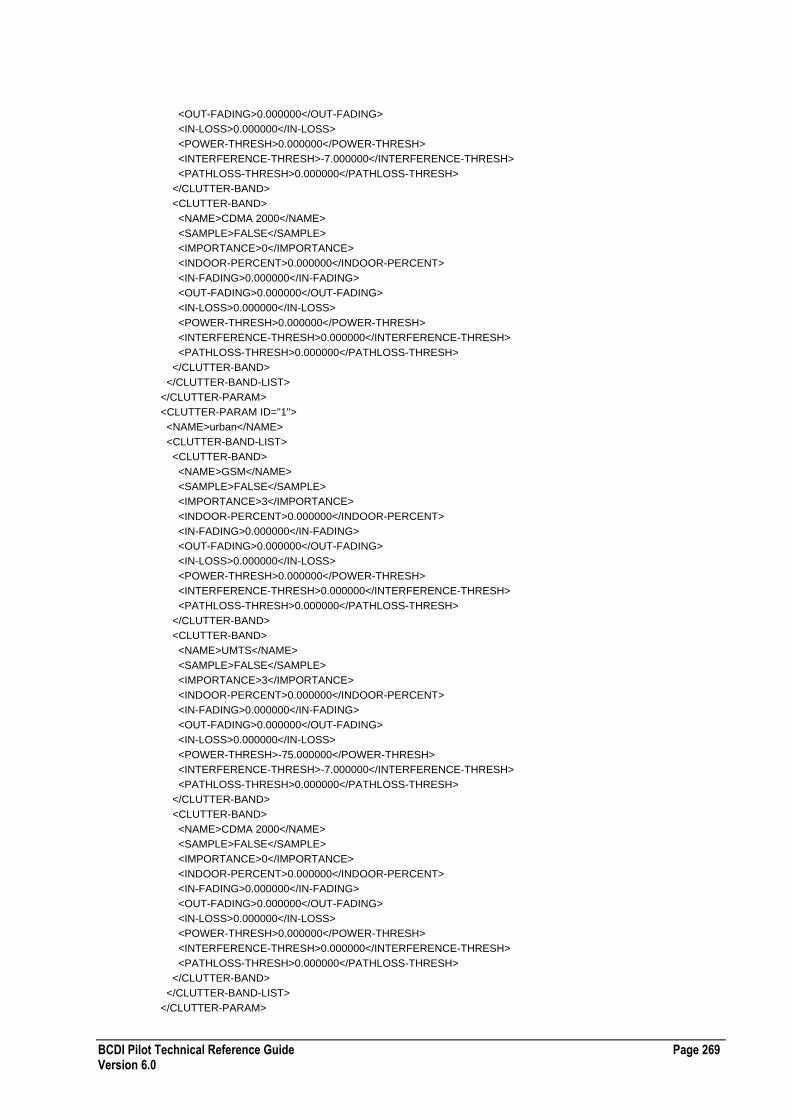
BCDI Pilot Technical Reference Guide Page 269 Version 6.0
<OUT-FADING>0.000000</OUT-FADING>
<IN-LOSS>0.000000</IN-LOSS>
<POWER-THRESH>0.000000</POWER-THRESH>
<INTERFERENCE-THRESH>-7.000000</INTERFERENCE-THRESH>
<PATHLOSS-THRESH>0.000000</PATHLOSS-THRESH>
</CLUTTER-BAND>
<CLUTTER-BAND>
<NAME>CDMA 2000</NAME>
<SAMPLE>FALSE</SAMPLE>
<IMPORTANCE>0</IMPORTANCE>
<INDOOR-PERCENT>0.000000</INDOOR-PERCENT>
<IN-FADING>0.000000</IN-FADING>
<OUT-FADING>0.000000</OUT-FADING>
<IN-LOSS>0.000000</IN-LOSS>
<POWER-THRESH>0.000000</POWER-THRESH>
<INTERFERENCE-THRESH>0.000000</INTERFERENCE-THRESH>
<PATHLOSS-THRESH>0.000000</PATHLOSS-THRESH>
</CLUTTER-BAND>
</CLUTTER-BAND-LIST>
</CLUTTER-PARAM>
<CLUTTER-PARAM ID="1">
<NAME>urban</NAME>
<CLUTTER-BAND-LIST>
<CLUTTER-BAND>
<NAME>GSM</NAME>
<SAMPLE>FALSE</SAMPLE>
<IMPORTANCE>3</IMPORTANCE>
<INDOOR-PERCENT>0.000000</INDOOR-PERCENT>
<IN-FADING>0.000000</IN-FADING>
<OUT-FADING>0.000000</OUT-FADING>
<IN-LOSS>0.000000</IN-LOSS>
<POWER-THRESH>0.000000</POWER-THRESH>
<INTERFERENCE-THRESH>0.000000</INTERFERENCE-THRESH>
<PATHLOSS-THRESH>0.000000</PATHLOSS-THRESH>
</CLUTTER-BAND>
<CLUTTER-BAND>
<NAME>UMTS</NAME>
<SAMPLE>FALSE</SAMPLE>
<IMPORTANCE>3</IMPORTANCE>
<INDOOR-PERCENT>0.000000</INDOOR-PERCENT>
<IN-FADING>0.000000</IN-FADING>
<OUT-FADING>0.000000</OUT-FADING>
<IN-LOSS>0.000000</IN-LOSS>
<POWER-THRESH>-75.000000</POWER-THRESH>
<INTERFERENCE-THRESH>-7.000000</INTERFERENCE-THRESH>
<PATHLOSS-THRESH>0.000000</PATHLOSS-THRESH>
</CLUTTER-BAND>
<CLUTTER-BAND>
<NAME>CDMA 2000</NAME>
<SAMPLE>FALSE</SAMPLE>
<IMPORTANCE>0</IMPORTANCE>
<INDOOR-PERCENT>0.000000</INDOOR-PERCENT>
<IN-FADING>0.000000</IN-FADING>
<OUT-FADING>0.000000</OUT-FADING>
<IN-LOSS>0.000000</IN-LOSS>
<POWER-THRESH>0.000000</POWER-THRESH>
<INTERFERENCE-THRESH>0.000000</INTERFERENCE-THRESH>
<PATHLOSS-THRESH>0.000000</PATHLOSS-THRESH>
</CLUTTER-BAND>
</CLUTTER-BAND-LIST>
</CLUTTER-PARAM>
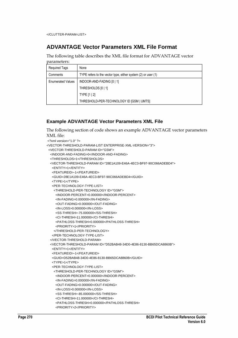
Page 270 BCDI Pilot Technical Reference Guide Version 6.0
</CLUTTER-PARAM-LIST>
ADVANTAGE Vector Parameters XML File Format
The following table describes the XML file format for ADVANTAGE vector parameters:
Required Tags None
Comments TYPE refers to the vector type, either system (2) or user (1)
Enumerated Values INDOOR-AND-FADING [0 | 1]
THRESHOLDS [0 | 1]
TYPE [1 | 2]
THRESHOLD-PER-TECHNOLOGY ID [GSM | UMTS]
Example ADVANTAGE Vector Parameters XML File
The following section of code shows an example ADVANTAGE vector parameters XML file: <?xml version="1.0" ?>
<VECTOR-THRESHOLD-PARAM-LIST ENTERPRISE-XML-VERSION="3">
<VECTOR-THRESHOLD-PARAM ID="GSM">
<INDOOR-AND-FADING>0</INDOOR-AND-FADING>
<THRESHOLDS>1</THRESHOLDS>
<VECTOR-THRESHOLD-PARAM ID="28E1A109-E46A-4EC3-BF97-90C066ADEBD4">
<ENTITY>1</ENTITY>
<FEATUREID>-1</FEATUREID>
<GUID>28E1A109-E46A-4EC3-BF97-90C066ADEBD4</GUID>
<TYPE>1</TYPE>
<PER-TECHNOLOGY-TYPE-LIST>
<THRESHOLD-PER-TECHNOLOGY ID="GSM">
<INDOOR-PERCENT>0.000000</INDOOR-PERCENT>
<IN-FADING>0.000000</IN-FADING>
<OUT-FADING>0.000000</OUT-FADING>
<IN-LOSS>0.000000</IN-LOSS>
<SS-THRESH>-75.000000</SS-THRESH>
<CI-THRESH>11.000000</CI-THRESH>
<PATHLOSS-THRESH>0.000000</PATHLOSS-THRESH>
<PRIORITY>1</PRIORITY>
</THRESHOLD-PER-TECHNOLOGY>
</PER-TECHNOLOGY-TYPE-LIST>
</VECTOR-THRESHOLD-PARAM>
<VECTOR-THRESHOLD-PARAM ID="D52BAB48-34D0-4E86-8130-BB65DCA8860B">
<ENTITY>1</ENTITY>
<FEATUREID>-1</FEATUREID>
<GUID>D52BAB48-34D0-4E86-8130-BB65DCA8860B</GUID>
<TYPE>1</TYPE>
<PER-TECHNOLOGY-TYPE-LIST>
<THRESHOLD-PER-TECHNOLOGY ID="GSM">
<INDOOR-PERCENT>0.000000</INDOOR-PERCENT>
<IN-FADING>0.000000</IN-FADING>
<OUT-FADING>0.000000</OUT-FADING>
<IN-LOSS>0.000000</IN-LOSS>
<SS-THRESH>-85.000000</SS-THRESH>
<CI-THRESH>11.000000</CI-THRESH>
<PATHLOSS-THRESH>0.000000</PATHLOSS-THRESH>
<PRIORITY>2</PRIORITY>
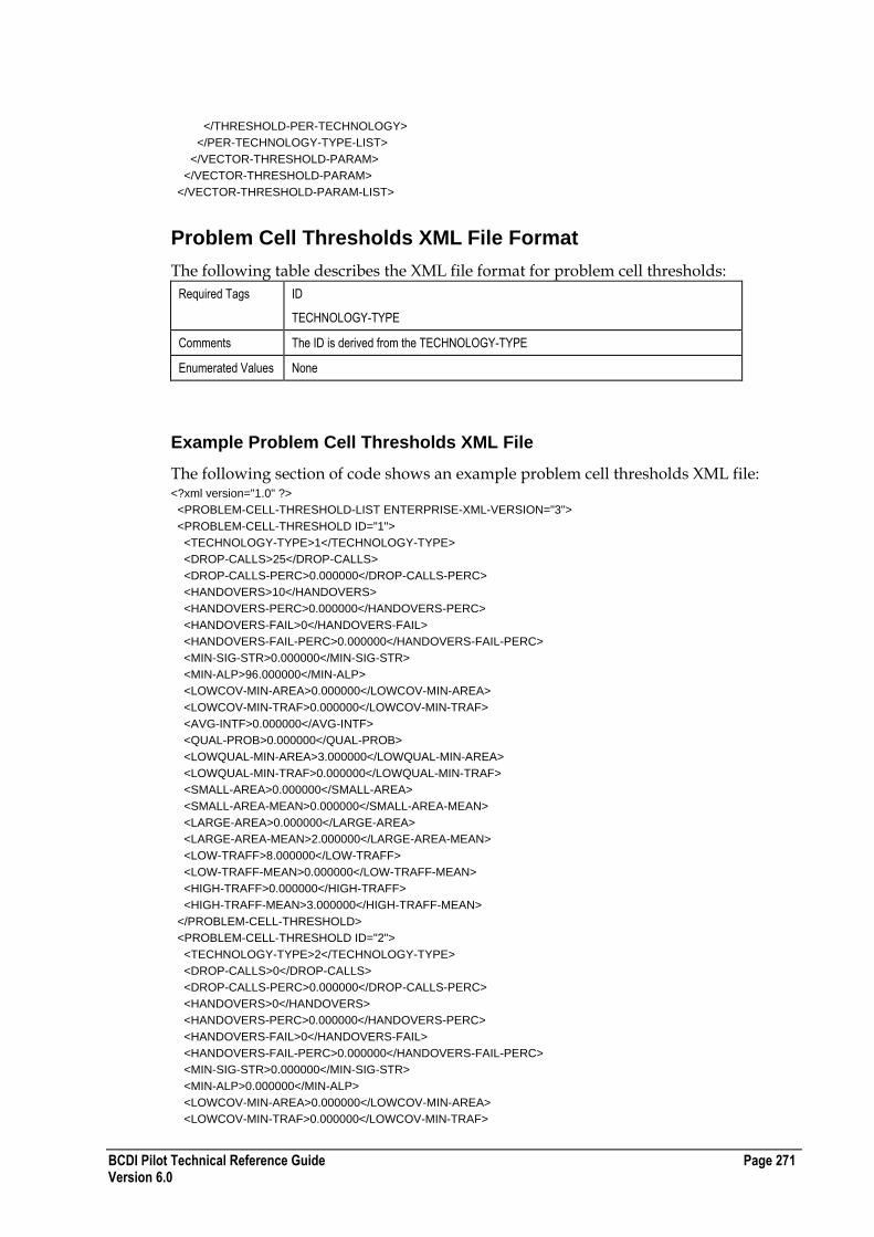
BCDI Pilot Technical Reference Guide Page 271 Version 6.0
</THRESHOLD-PER-TECHNOLOGY>
</PER-TECHNOLOGY-TYPE-LIST>
</VECTOR-THRESHOLD-PARAM>
</VECTOR-THRESHOLD-PARAM>
</VECTOR-THRESHOLD-PARAM-LIST>
Problem Cell Thresholds XML File Format
The following table describes the XML file format for problem cell thresholds:
Required Tags ID
TECHNOLOGY-TYPE
Comments The ID is derived from the TECHNOLOGY-TYPE
Enumerated Values None
Example Problem Cell Thresholds XML File
The following section of code shows an example problem cell thresholds XML file: <?xml version="1.0" ?>
<PROBLEM-CELL-THRESHOLD-LIST ENTERPRISE-XML-VERSION="3">
<PROBLEM-CELL-THRESHOLD ID="1">
<TECHNOLOGY-TYPE>1</TECHNOLOGY-TYPE>
<DROP-CALLS>25</DROP-CALLS>
<DROP-CALLS-PERC>0.000000</DROP-CALLS-PERC>
<HANDOVERS>10</HANDOVERS>
<HANDOVERS-PERC>0.000000</HANDOVERS-PERC>
<HANDOVERS-FAIL>0</HANDOVERS-FAIL>
<HANDOVERS-FAIL-PERC>0.000000</HANDOVERS-FAIL-PERC>
<MIN-SIG-STR>0.000000</MIN-SIG-STR>
<MIN-ALP>96.000000</MIN-ALP>
<LOWCOV-MIN-AREA>0.000000</LOWCOV-MIN-AREA>
<LOWCOV-MIN-TRAF>0.000000</LOWCOV-MIN-TRAF>
<AVG-INTF>0.000000</AVG-INTF>
<QUAL-PROB>0.000000</QUAL-PROB>
<LOWQUAL-MIN-AREA>3.000000</LOWQUAL-MIN-AREA>
<LOWQUAL-MIN-TRAF>0.000000</LOWQUAL-MIN-TRAF>
<SMALL-AREA>0.000000</SMALL-AREA>
<SMALL-AREA-MEAN>0.000000</SMALL-AREA-MEAN>
<LARGE-AREA>0.000000</LARGE-AREA>
<LARGE-AREA-MEAN>2.000000</LARGE-AREA-MEAN>
<LOW-TRAFF>8.000000</LOW-TRAFF>
<LOW-TRAFF-MEAN>0.000000</LOW-TRAFF-MEAN>
<HIGH-TRAFF>0.000000</HIGH-TRAFF>
<HIGH-TRAFF-MEAN>3.000000</HIGH-TRAFF-MEAN>
</PROBLEM-CELL-THRESHOLD>
<PROBLEM-CELL-THRESHOLD ID="2">
<TECHNOLOGY-TYPE>2</TECHNOLOGY-TYPE>
<DROP-CALLS>0</DROP-CALLS>
<DROP-CALLS-PERC>0.000000</DROP-CALLS-PERC>
<HANDOVERS>0</HANDOVERS>
<HANDOVERS-PERC>0.000000</HANDOVERS-PERC>
<HANDOVERS-FAIL>0</HANDOVERS-FAIL>
<HANDOVERS-FAIL-PERC>0.000000</HANDOVERS-FAIL-PERC>
<MIN-SIG-STR>0.000000</MIN-SIG-STR>
<MIN-ALP>0.000000</MIN-ALP>
<LOWCOV-MIN-AREA>0.000000</LOWCOV-MIN-AREA>
<LOWCOV-MIN-TRAF>0.000000</LOWCOV-MIN-TRAF>

Page 272 BCDI Pilot Technical Reference Guide Version 6.0
<AVG-INTF>0.000000</AVG-INTF>
<QUAL-PROB>0.000000</QUAL-PROB>
<LOWQUAL-MIN-AREA>0.000000</LOWQUAL-MIN-AREA>
<LOWQUAL-MIN-TRAF>0.000000</LOWQUAL-MIN-TRAF>
<SMALL-AREA>0.000000</SMALL-AREA>
<SMALL-AREA-MEAN>0.000000</SMALL-AREA-MEAN>
<LARGE-AREA>0.000000</LARGE-AREA>
<LARGE-AREA-MEAN>0.000000</LARGE-AREA-MEAN>
<LOW-TRAFF>0.000000</LOW-TRAFF>
<LOW-TRAFF-MEAN>0.000000</LOW-TRAFF-MEAN>
<HIGH-TRAFF>0.000000</HIGH-TRAFF>
<HIGH-TRAFF-MEAN>0.000000</HIGH-TRAFF-MEAN>
</PROBLEM-CELL-THRESHOLD>
</PROBLEM-CELL-THRESHOLD-LIST>
Problem Area Thresholds XML File Format
The following table describes the XML file format for problem area thresholds:
Required Tags TECHNOLOGY-TYPE
CLUTTER
Comments The ID is derived from the TECHNOLOGY-TYPE and CLUTTER.
CLUTTER must match the mapping data.
Enumerated Values TECHNOLOGY-TYPE
Example Problem Area Thresholds XML File
The following section of code shows an example problem area thresholds XML file: <?xml version="1.0" ?>
<PROBLEM-AREA-THRESHOLD-LIST ENTERPRISE-XML-VERSION="3">
<PROBLEM-AREA-THRESHOLD ID="1_0">
<TECHNOLOGY-TYPE>1</TECHNOLOGY-TYPE>
<CLUTTER>0</CLUTTER>
<INTF-TRAF>0.000000</INTF-TRAF>
<DOMI-TRAF>0.000000</DOMI-TRAF>
<COVR-TRAF>0.000000</COVR-TRAF>
<INTF-AREA>0.000000</INTF-AREA>
<DOMI-AREA>0.000000</DOMI-AREA>
<COVR-AREA>0.000000</COVR-AREA>
<INTF-THRESH>0.000000</INTF-THRESH>
<DOMI-THRESH>0.000000</DOMI-THRESH>
<COVR-THRESH>0.000000</COVR-THRESH>
</PROBLEM-AREA-THRESHOLD>
<PROBLEM-AREA-THRESHOLD ID="1_1">
<TECHNOLOGY-TYPE>1</TECHNOLOGY-TYPE>
<CLUTTER>1</CLUTTER>
<INTF-TRAF>10.000000</INTF-TRAF>
<DOMI-TRAF>0.000000</DOMI-TRAF>
<COVR-TRAF>10.000000</COVR-TRAF>
<INTF-AREA>2.000000</INTF-AREA>
<DOMI-AREA>0.000000</DOMI-AREA>
<COVR-AREA>2.000000</COVR-AREA>
<INTF-THRESH>20.000000</INTF-THRESH>
<DOMI-THRESH>0.000000</DOMI-THRESH>
<COVR-THRESH>-100.000000</COVR-THRESH>
</PROBLEM-AREA-THRESHOLD>
<PROBLEM-AREA-THRESHOLD ID="1_2">

BCDI Pilot Technical Reference Guide Page 273 Version 6.0
<TECHNOLOGY-TYPE>1</TECHNOLOGY-TYPE>
<CLUTTER>2</CLUTTER>
<INTF-TRAF>7.000000</INTF-TRAF>
<DOMI-TRAF>0.000000</DOMI-TRAF>
<COVR-TRAF>7.000000</COVR-TRAF>
<INTF-AREA>1.000000</INTF-AREA>
<DOMI-AREA>0.000000</DOMI-AREA>
<COVR-AREA>1.000000</COVR-AREA>
<INTF-THRESH>15.000000</INTF-THRESH>
<DOMI-THRESH>0.000000</DOMI-THRESH>
<COVR-THRESH>-100.000000</COVR-THRESH>
</PROBLEM-AREA-THRESHOLD>
<PROBLEM-AREA-THRESHOLD ID="1_3">
<TECHNOLOGY-TYPE>1</TECHNOLOGY-TYPE>
<CLUTTER>3</CLUTTER>
<INTF-TRAF>3.000000</INTF-TRAF>
<DOMI-TRAF>0.000000</DOMI-TRAF>
<COVR-TRAF>3.000000</COVR-TRAF>
<INTF-AREA>1.000000</INTF-AREA>
<DOMI-AREA>0.000000</DOMI-AREA>
<COVR-AREA>1.000000</COVR-AREA>
<INTF-THRESH>15.000000</INTF-THRESH>
<DOMI-THRESH>0.000000</DOMI-THRESH>
<COVR-THRESH>-100.000000</COVR-THRESH>
</PROBLEM-AREA-THRESHOLD>
<PROBLEM-AREA-THRESHOLD ID="1_4">
<TECHNOLOGY-TYPE>1</TECHNOLOGY-TYPE>
<CLUTTER>4</CLUTTER>
<INTF-TRAF>0.000000</INTF-TRAF>
<DOMI-TRAF>0.000000</DOMI-TRAF>
<COVR-TRAF>0.000000</COVR-TRAF>
<INTF-AREA>0.000000</INTF-AREA>
<DOMI-AREA>0.000000</DOMI-AREA>
<COVR-AREA>0.000000</COVR-AREA>
<INTF-THRESH>0.000000</INTF-THRESH>
<DOMI-THRESH>0.000000</DOMI-THRESH>
<COVR-THRESH>0.000000</COVR-THRESH>
</PROBLEM-AREA-THRESHOLD>
<PROBLEM-AREA-THRESHOLD ID="1_5">
<TECHNOLOGY-TYPE>1</TECHNOLOGY-TYPE>
<CLUTTER>5</CLUTTER>
<INTF-TRAF>1.000000</INTF-TRAF>
<DOMI-TRAF>0.000000</DOMI-TRAF>
<COVR-TRAF>1.000000</COVR-TRAF>
<INTF-AREA>1.000000</INTF-AREA>
<DOMI-AREA>0.000000</DOMI-AREA>
<COVR-AREA>1.000000</COVR-AREA>
<INTF-THRESH>5.000000</INTF-THRESH>
<DOMI-THRESH>0.000000</DOMI-THRESH>
<COVR-THRESH>-80.000000</COVR-THRESH>
</PROBLEM-AREA-THRESHOLD>
<PROBLEM-AREA-THRESHOLD ID="1_6">
<TECHNOLOGY-TYPE>1</TECHNOLOGY-TYPE>
<CLUTTER>6</CLUTTER>
<INTF-TRAF>0.000000</INTF-TRAF>
<DOMI-TRAF>0.000000</DOMI-TRAF>
<COVR-TRAF>0.000000</COVR-TRAF>
<INTF-AREA>0.000000</INTF-AREA>
<DOMI-AREA>0.000000</DOMI-AREA>
<COVR-AREA>0.000000</COVR-AREA>
<INTF-THRESH>0.000000</INTF-THRESH>
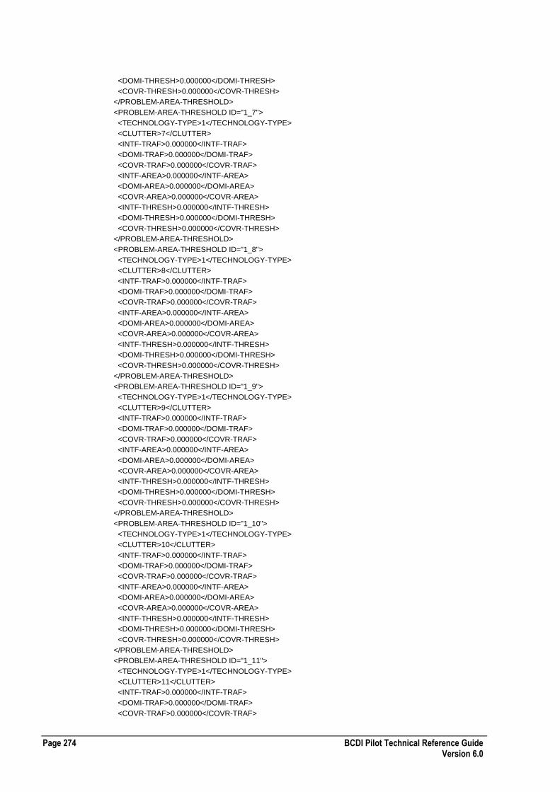
Page 274 BCDI Pilot Technical Reference Guide Version 6.0
<DOMI-THRESH>0.000000</DOMI-THRESH>
<COVR-THRESH>0.000000</COVR-THRESH>
</PROBLEM-AREA-THRESHOLD>
<PROBLEM-AREA-THRESHOLD ID="1_7">
<TECHNOLOGY-TYPE>1</TECHNOLOGY-TYPE>
<CLUTTER>7</CLUTTER>
<INTF-TRAF>0.000000</INTF-TRAF>
<DOMI-TRAF>0.000000</DOMI-TRAF>
<COVR-TRAF>0.000000</COVR-TRAF>
<INTF-AREA>0.000000</INTF-AREA>
<DOMI-AREA>0.000000</DOMI-AREA>
<COVR-AREA>0.000000</COVR-AREA>
<INTF-THRESH>0.000000</INTF-THRESH>
<DOMI-THRESH>0.000000</DOMI-THRESH>
<COVR-THRESH>0.000000</COVR-THRESH>
</PROBLEM-AREA-THRESHOLD>
<PROBLEM-AREA-THRESHOLD ID="1_8">
<TECHNOLOGY-TYPE>1</TECHNOLOGY-TYPE>
<CLUTTER>8</CLUTTER>
<INTF-TRAF>0.000000</INTF-TRAF>
<DOMI-TRAF>0.000000</DOMI-TRAF>
<COVR-TRAF>0.000000</COVR-TRAF>
<INTF-AREA>0.000000</INTF-AREA>
<DOMI-AREA>0.000000</DOMI-AREA>
<COVR-AREA>0.000000</COVR-AREA>
<INTF-THRESH>0.000000</INTF-THRESH>
<DOMI-THRESH>0.000000</DOMI-THRESH>
<COVR-THRESH>0.000000</COVR-THRESH>
</PROBLEM-AREA-THRESHOLD>
<PROBLEM-AREA-THRESHOLD ID="1_9">
<TECHNOLOGY-TYPE>1</TECHNOLOGY-TYPE>
<CLUTTER>9</CLUTTER>
<INTF-TRAF>0.000000</INTF-TRAF>
<DOMI-TRAF>0.000000</DOMI-TRAF>
<COVR-TRAF>0.000000</COVR-TRAF>
<INTF-AREA>0.000000</INTF-AREA>
<DOMI-AREA>0.000000</DOMI-AREA>
<COVR-AREA>0.000000</COVR-AREA>
<INTF-THRESH>0.000000</INTF-THRESH>
<DOMI-THRESH>0.000000</DOMI-THRESH>
<COVR-THRESH>0.000000</COVR-THRESH>
</PROBLEM-AREA-THRESHOLD>
<PROBLEM-AREA-THRESHOLD ID="1_10">
<TECHNOLOGY-TYPE>1</TECHNOLOGY-TYPE>
<CLUTTER>10</CLUTTER>
<INTF-TRAF>0.000000</INTF-TRAF>
<DOMI-TRAF>0.000000</DOMI-TRAF>
<COVR-TRAF>0.000000</COVR-TRAF>
<INTF-AREA>0.000000</INTF-AREA>
<DOMI-AREA>0.000000</DOMI-AREA>
<COVR-AREA>0.000000</COVR-AREA>
<INTF-THRESH>0.000000</INTF-THRESH>
<DOMI-THRESH>0.000000</DOMI-THRESH>
<COVR-THRESH>0.000000</COVR-THRESH>
</PROBLEM-AREA-THRESHOLD>
<PROBLEM-AREA-THRESHOLD ID="1_11">
<TECHNOLOGY-TYPE>1</TECHNOLOGY-TYPE>
<CLUTTER>11</CLUTTER>
<INTF-TRAF>0.000000</INTF-TRAF>
<DOMI-TRAF>0.000000</DOMI-TRAF>
<COVR-TRAF>0.000000</COVR-TRAF>

BCDI Pilot Technical Reference Guide Page 275 Version 6.0
<INTF-AREA>0.000000</INTF-AREA>
<DOMI-AREA>0.000000</DOMI-AREA>
<COVR-AREA>0.000000</COVR-AREA>
<INTF-THRESH>0.000000</INTF-THRESH>
<DOMI-THRESH>0.000000</DOMI-THRESH>
<COVR-THRESH>0.000000</COVR-THRESH>
</PROBLEM-AREA-THRESHOLD>
<PROBLEM-AREA-THRESHOLD ID="1_12">
<TECHNOLOGY-TYPE>1</TECHNOLOGY-TYPE>
<CLUTTER>12</CLUTTER>
<INTF-TRAF>0.000000</INTF-TRAF>
<DOMI-TRAF>0.000000</DOMI-TRAF>
<COVR-TRAF>0.000000</COVR-TRAF>
<INTF-AREA>0.000000</INTF-AREA>
<DOMI-AREA>0.000000</DOMI-AREA>
<COVR-AREA>0.000000</COVR-AREA>
<INTF-THRESH>0.000000</INTF-THRESH>
<DOMI-THRESH>0.000000</DOMI-THRESH>
<COVR-THRESH>0.000000</COVR-THRESH>
</PROBLEM-AREA-THRESHOLD>
<PROBLEM-AREA-THRESHOLD ID="1_13">
<TECHNOLOGY-TYPE>1</TECHNOLOGY-TYPE>
<CLUTTER>13</CLUTTER>
<INTF-TRAF>0.000000</INTF-TRAF>
<DOMI-TRAF>0.000000</DOMI-TRAF>
<COVR-TRAF>0.000000</COVR-TRAF>
<INTF-AREA>0.000000</INTF-AREA>
<DOMI-AREA>0.000000</DOMI-AREA>
<COVR-AREA>0.000000</COVR-AREA>
<INTF-THRESH>0.000000</INTF-THRESH>
<DOMI-THRESH>0.000000</DOMI-THRESH>
<COVR-THRESH>0.000000</COVR-THRESH>
</PROBLEM-AREA-THRESHOLD>
<PROBLEM-AREA-THRESHOLD ID="1_14">
<TECHNOLOGY-TYPE>1</TECHNOLOGY-TYPE>
<CLUTTER>14</CLUTTER>
<INTF-TRAF>0.000000</INTF-TRAF>
<DOMI-TRAF>0.000000</DOMI-TRAF>
<COVR-TRAF>0.000000</COVR-TRAF>
<INTF-AREA>0.000000</INTF-AREA>
<DOMI-AREA>0.000000</DOMI-AREA>
<COVR-AREA>0.000000</COVR-AREA>
<INTF-THRESH>0.000000</INTF-THRESH>
<DOMI-THRESH>0.000000</DOMI-THRESH>
<COVR-THRESH>0.000000</COVR-THRESH>
</PROBLEM-AREA-THRESHOLD>
<PROBLEM-AREA-THRESHOLD ID="1_24">
<TECHNOLOGY-TYPE>1</TECHNOLOGY-TYPE>
<CLUTTER>24</CLUTTER>
<INTF-TRAF>0.000000</INTF-TRAF>
<DOMI-TRAF>0.000000</DOMI-TRAF>
<COVR-TRAF>0.000000</COVR-TRAF>
<INTF-AREA>0.000000</INTF-AREA>
<DOMI-AREA>0.000000</DOMI-AREA>
<COVR-AREA>0.000000</COVR-AREA>
<INTF-THRESH>0.000000</INTF-THRESH>
<DOMI-THRESH>0.000000</DOMI-THRESH>
<COVR-THRESH>0.000000</COVR-THRESH>
</PROBLEM-AREA-THRESHOLD>
</PROBLEM-AREA-THRESHOLD-LIST>

Page 276 BCDI Pilot Technical Reference Guide Version 6.0
Action Combination Options XML File Format
The following table describes the XML file format for action combination options:
Required Tags None
Comments There is only 1 entry per project
Enumerated Values COMBINATION-LEVEL
COMBINATION-TYPE
CONSIDER-REMOTE
Example Action Combination Options XML File
The following section of code shows an example action combination options XML file: <?xml version="1.0" ?>
<ACTION-COMBINATION-OPTIONS-LIST ENTERPRISE-XML-VERSION="3">
<ACTION-COMBINATION-OPTIONS ACTION-COMBINATIONS="ActionCombinations">
<COMBINATION-LEVEL>5</COMBINATION-LEVEL>
<COMBINATION-TYPE>1</COMBINATION-TYPE>
<CONSIDER-REMOTE>0</CONSIDER-REMOTE>
</ACTION-COMBINATION-OPTIONS>
</ACTION-COMBINATION-OPTIONS-LIST>
Max Units/Actions XML File Format
The following table describes the XML file format for max units/actions:
Required Tags All
Comments The GLOBAL_MAX_CONSTRAINT represents the 'Reject Plans Based on Max Units/Actions' checkbox.
Enumerated Values ACTIVE
CONSTRAINT-NAME
Example Max Units/Actions XML File
The following section of code shows an example max units/actions XML file: <?xml version="1.0" ?>
<MAX-UNITS-ACTIONS-LIST ENTERPRISE-XML-VERSION="3">
<MAX-UNITS-ACTIONS MAX-ACTION-CONSTRAINTS="MaxActionConstraints">
<CONSTRAINT-NAME>GLOBAL_MAX_CONSTRAINT</CONSTRAINT-NAME>
<CONSTRAINT>0</CONSTRAINT>
<ACTIVE>1</ACTIVE>
</MAX-UNITS-ACTIONS>
<MAX-UNITS-ACTIONS MAX-ACTION-CONSTRAINTS="MaxActionConstraints">
<CONSTRAINT-NAME>ANTENNA_UNIT</CONSTRAINT-NAME>
<CONSTRAINT>12</CONSTRAINT>
<ACTIVE>1</ACTIVE>
</MAX-UNITS-ACTIONS>
<MAX-UNITS-ACTIONS MAX-ACTION-CONSTRAINTS="MaxActionConstraints">
<CONSTRAINT-NAME>PROPERTY_UNIT</CONSTRAINT-NAME>
<CONSTRAINT>3</CONSTRAINT>
<ACTIVE>1</ACTIVE>

BCDI Pilot Technical Reference Guide Page 277 Version 6.0
</MAX-UNITS-ACTIONS>
<MAX-UNITS-ACTIONS MAX-ACTION-CONSTRAINTS="MaxActionConstraints">
<CONSTRAINT-NAME>SITE_UNIT</CONSTRAINT-NAME>
<CONSTRAINT>0</CONSTRAINT>
<ACTIVE>0</ACTIVE>
</MAX-UNITS-ACTIONS>
<MAX-UNITS-ACTIONS MAX-ACTION-CONSTRAINTS="MaxActionConstraints">
<CONSTRAINT-NAME>CELL_UNIT</CONSTRAINT-NAME>
<CONSTRAINT>0</CONSTRAINT>
<ACTIVE>0</ACTIVE>
</MAX-UNITS-ACTIONS>
<MAX-UNITS-ACTIONS MAX-ACTION-CONSTRAINTS="MaxActionConstraints">
<CONSTRAINT-NAME>COMBINED_ACTIONS</CONSTRAINT-NAME>
<CONSTRAINT>8</CONSTRAINT>
<ACTIVE>1</ACTIVE>
</MAX-UNITS-ACTIONS>
<MAX-UNITS-ACTIONS MAX-ACTION-CONSTRAINTS="MaxActionConstraints">
<CONSTRAINT-NAME>ANTENNA_ACTIONS</CONSTRAINT-NAME>
<CONSTRAINT>4</CONSTRAINT>
<ACTIVE>1</ACTIVE>
</MAX-UNITS-ACTIONS>
<MAX-UNITS-ACTIONS MAX-ACTION-CONSTRAINTS="MaxActionConstraints">
<CONSTRAINT-NAME>POWER_ACTIONS</CONSTRAINT-NAME>
<CONSTRAINT>4</CONSTRAINT>
<ACTIVE>1</ACTIVE>
</MAX-UNITS-ACTIONS>
<MAX-UNITS-ACTIONS MAX-ACTION-CONSTRAINTS="MaxActionConstraints">
<CONSTRAINT-NAME>GRID_ACTIONS</CONSTRAINT-NAME>
<CONSTRAINT>0</CONSTRAINT>
<ACTIVE>0</ACTIVE>
</MAX-UNITS-ACTIONS>
</MAX-UNITS-ACTIONS-LIST>
Cost Function Weights XML File Format
The following table describes the XML file format for cost function weights:
Required Tags All
Comments The METRIC-TYPE value of -1 represents the Global Coefficients pane, and the WEIGHT value for this METRIC TYPE represents the % Traffic value.
Enumerated Values METRIC TYPE
MECH-TECHNOLOGY
ACTIVE
Example Cost Function Weights XML File
The following section of code shows an example cost function weights XML file: <?xml version="1.0" ?>
<COST-FUNCTION-WEIGHTS-LIST ENTERPRISE-XML-VERSION="3">
<COST-FUNCTION-WEIGHTS COST-FUNCTION-WEIGHTS="CostFunctionWeights">
<METRIC-TYPE>-1</METRIC-TYPE>
<METRIC-ENUM>0</METRIC-ENUM>
<WEIGHT>0.000000</WEIGHT>
<MECH-TECHNOLOGY>0</MECH-TECHNOLOGY>
<ACTIVE>1</ACTIVE>
</COST-FUNCTION-WEIGHTS>
<COST-FUNCTION-WEIGHTS COST-FUNCTION-WEIGHTS="CostFunctionWeights">
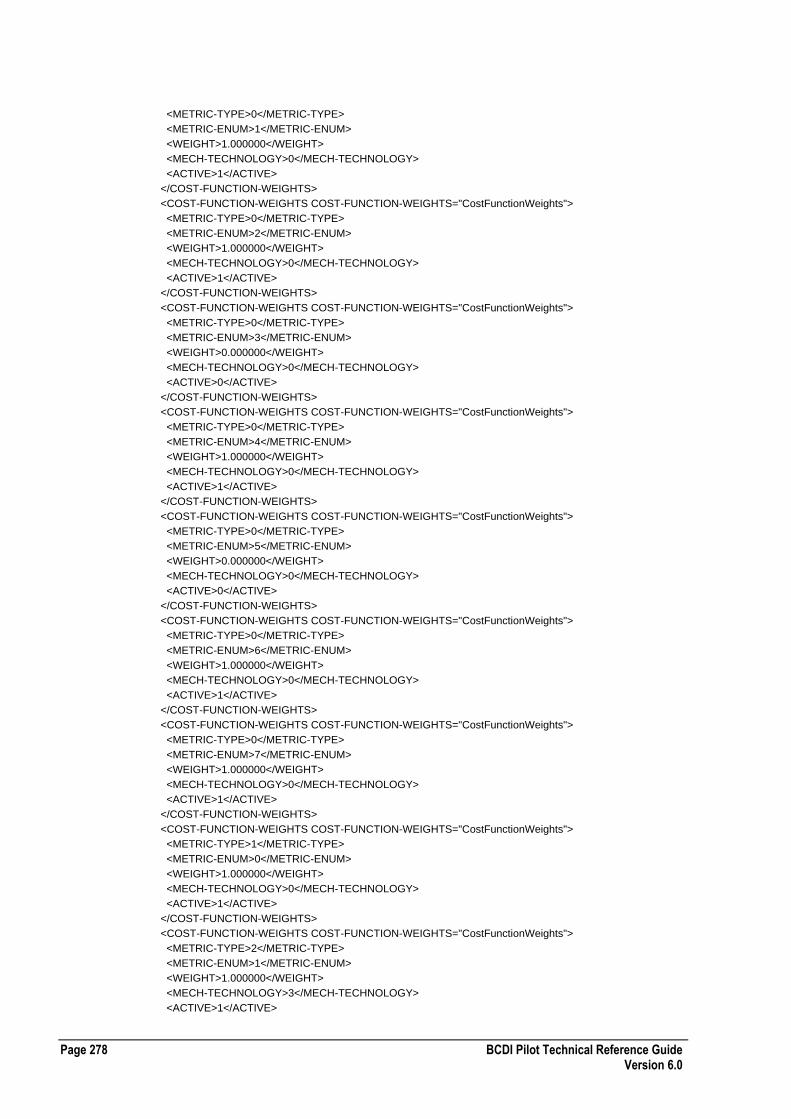
Page 278 BCDI Pilot Technical Reference Guide Version 6.0
<METRIC-TYPE>0</METRIC-TYPE>
<METRIC-ENUM>1</METRIC-ENUM>
<WEIGHT>1.000000</WEIGHT>
<MECH-TECHNOLOGY>0</MECH-TECHNOLOGY>
<ACTIVE>1</ACTIVE>
</COST-FUNCTION-WEIGHTS>
<COST-FUNCTION-WEIGHTS COST-FUNCTION-WEIGHTS="CostFunctionWeights">
<METRIC-TYPE>0</METRIC-TYPE>
<METRIC-ENUM>2</METRIC-ENUM>
<WEIGHT>1.000000</WEIGHT>
<MECH-TECHNOLOGY>0</MECH-TECHNOLOGY>
<ACTIVE>1</ACTIVE>
</COST-FUNCTION-WEIGHTS>
<COST-FUNCTION-WEIGHTS COST-FUNCTION-WEIGHTS="CostFunctionWeights">
<METRIC-TYPE>0</METRIC-TYPE>
<METRIC-ENUM>3</METRIC-ENUM>
<WEIGHT>0.000000</WEIGHT>
<MECH-TECHNOLOGY>0</MECH-TECHNOLOGY>
<ACTIVE>0</ACTIVE>
</COST-FUNCTION-WEIGHTS>
<COST-FUNCTION-WEIGHTS COST-FUNCTION-WEIGHTS="CostFunctionWeights">
<METRIC-TYPE>0</METRIC-TYPE>
<METRIC-ENUM>4</METRIC-ENUM>
<WEIGHT>1.000000</WEIGHT>
<MECH-TECHNOLOGY>0</MECH-TECHNOLOGY>
<ACTIVE>1</ACTIVE>
</COST-FUNCTION-WEIGHTS>
<COST-FUNCTION-WEIGHTS COST-FUNCTION-WEIGHTS="CostFunctionWeights">
<METRIC-TYPE>0</METRIC-TYPE>
<METRIC-ENUM>5</METRIC-ENUM>
<WEIGHT>0.000000</WEIGHT>
<MECH-TECHNOLOGY>0</MECH-TECHNOLOGY>
<ACTIVE>0</ACTIVE>
</COST-FUNCTION-WEIGHTS>
<COST-FUNCTION-WEIGHTS COST-FUNCTION-WEIGHTS="CostFunctionWeights">
<METRIC-TYPE>0</METRIC-TYPE>
<METRIC-ENUM>6</METRIC-ENUM>
<WEIGHT>1.000000</WEIGHT>
<MECH-TECHNOLOGY>0</MECH-TECHNOLOGY>
<ACTIVE>1</ACTIVE>
</COST-FUNCTION-WEIGHTS>
<COST-FUNCTION-WEIGHTS COST-FUNCTION-WEIGHTS="CostFunctionWeights">
<METRIC-TYPE>0</METRIC-TYPE>
<METRIC-ENUM>7</METRIC-ENUM>
<WEIGHT>1.000000</WEIGHT>
<MECH-TECHNOLOGY>0</MECH-TECHNOLOGY>
<ACTIVE>1</ACTIVE>
</COST-FUNCTION-WEIGHTS>
<COST-FUNCTION-WEIGHTS COST-FUNCTION-WEIGHTS="CostFunctionWeights">
<METRIC-TYPE>1</METRIC-TYPE>
<METRIC-ENUM>0</METRIC-ENUM>
<WEIGHT>1.000000</WEIGHT>
<MECH-TECHNOLOGY>0</MECH-TECHNOLOGY>
<ACTIVE>1</ACTIVE>
</COST-FUNCTION-WEIGHTS>
<COST-FUNCTION-WEIGHTS COST-FUNCTION-WEIGHTS="CostFunctionWeights">
<METRIC-TYPE>2</METRIC-TYPE>
<METRIC-ENUM>1</METRIC-ENUM>
<WEIGHT>1.000000</WEIGHT>
<MECH-TECHNOLOGY>3</MECH-TECHNOLOGY>
<ACTIVE>1</ACTIVE>
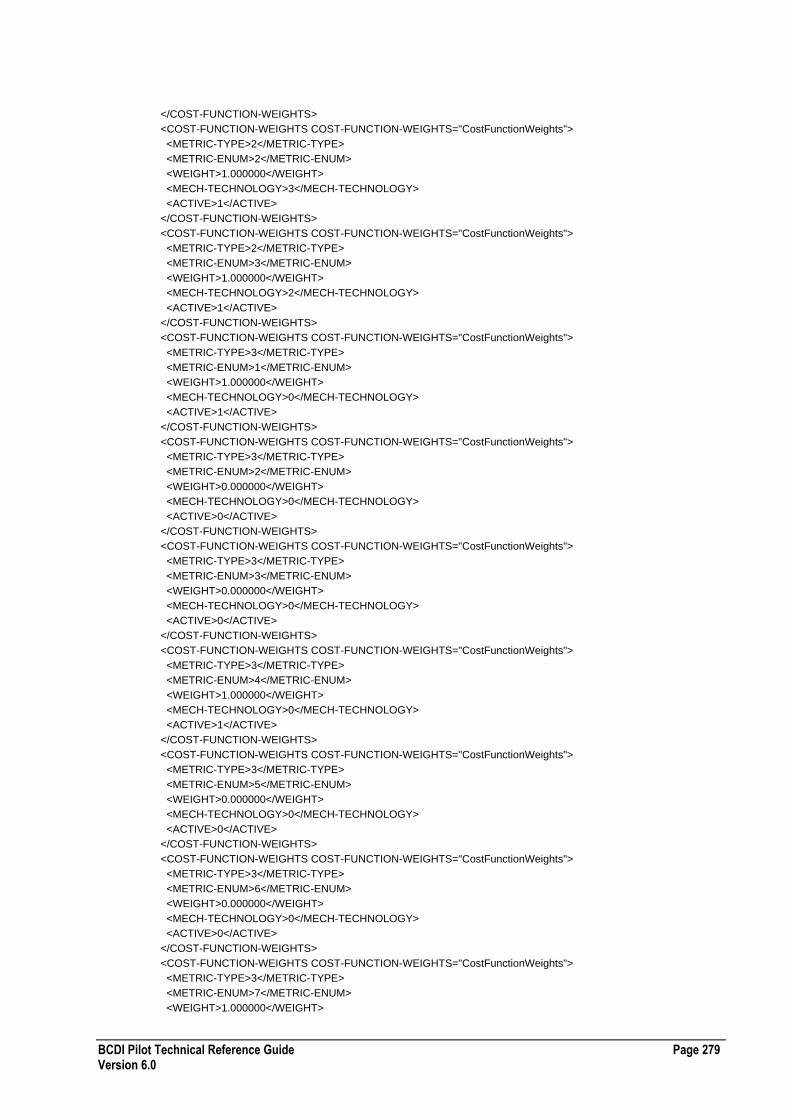
BCDI Pilot Technical Reference Guide Page 279 Version 6.0
</COST-FUNCTION-WEIGHTS>
<COST-FUNCTION-WEIGHTS COST-FUNCTION-WEIGHTS="CostFunctionWeights">
<METRIC-TYPE>2</METRIC-TYPE>
<METRIC-ENUM>2</METRIC-ENUM>
<WEIGHT>1.000000</WEIGHT>
<MECH-TECHNOLOGY>3</MECH-TECHNOLOGY>
<ACTIVE>1</ACTIVE>
</COST-FUNCTION-WEIGHTS>
<COST-FUNCTION-WEIGHTS COST-FUNCTION-WEIGHTS="CostFunctionWeights">
<METRIC-TYPE>2</METRIC-TYPE>
<METRIC-ENUM>3</METRIC-ENUM>
<WEIGHT>1.000000</WEIGHT>
<MECH-TECHNOLOGY>2</MECH-TECHNOLOGY>
<ACTIVE>1</ACTIVE>
</COST-FUNCTION-WEIGHTS>
<COST-FUNCTION-WEIGHTS COST-FUNCTION-WEIGHTS="CostFunctionWeights">
<METRIC-TYPE>3</METRIC-TYPE>
<METRIC-ENUM>1</METRIC-ENUM>
<WEIGHT>1.000000</WEIGHT>
<MECH-TECHNOLOGY>0</MECH-TECHNOLOGY>
<ACTIVE>1</ACTIVE>
</COST-FUNCTION-WEIGHTS>
<COST-FUNCTION-WEIGHTS COST-FUNCTION-WEIGHTS="CostFunctionWeights">
<METRIC-TYPE>3</METRIC-TYPE>
<METRIC-ENUM>2</METRIC-ENUM>
<WEIGHT>0.000000</WEIGHT>
<MECH-TECHNOLOGY>0</MECH-TECHNOLOGY>
<ACTIVE>0</ACTIVE>
</COST-FUNCTION-WEIGHTS>
<COST-FUNCTION-WEIGHTS COST-FUNCTION-WEIGHTS="CostFunctionWeights">
<METRIC-TYPE>3</METRIC-TYPE>
<METRIC-ENUM>3</METRIC-ENUM>
<WEIGHT>0.000000</WEIGHT>
<MECH-TECHNOLOGY>0</MECH-TECHNOLOGY>
<ACTIVE>0</ACTIVE>
</COST-FUNCTION-WEIGHTS>
<COST-FUNCTION-WEIGHTS COST-FUNCTION-WEIGHTS="CostFunctionWeights">
<METRIC-TYPE>3</METRIC-TYPE>
<METRIC-ENUM>4</METRIC-ENUM>
<WEIGHT>1.000000</WEIGHT>
<MECH-TECHNOLOGY>0</MECH-TECHNOLOGY>
<ACTIVE>1</ACTIVE>
</COST-FUNCTION-WEIGHTS>
<COST-FUNCTION-WEIGHTS COST-FUNCTION-WEIGHTS="CostFunctionWeights">
<METRIC-TYPE>3</METRIC-TYPE>
<METRIC-ENUM>5</METRIC-ENUM>
<WEIGHT>0.000000</WEIGHT>
<MECH-TECHNOLOGY>0</MECH-TECHNOLOGY>
<ACTIVE>0</ACTIVE>
</COST-FUNCTION-WEIGHTS>
<COST-FUNCTION-WEIGHTS COST-FUNCTION-WEIGHTS="CostFunctionWeights">
<METRIC-TYPE>3</METRIC-TYPE>
<METRIC-ENUM>6</METRIC-ENUM>
<WEIGHT>0.000000</WEIGHT>
<MECH-TECHNOLOGY>0</MECH-TECHNOLOGY>
<ACTIVE>0</ACTIVE>
</COST-FUNCTION-WEIGHTS>
<COST-FUNCTION-WEIGHTS COST-FUNCTION-WEIGHTS="CostFunctionWeights">
<METRIC-TYPE>3</METRIC-TYPE>
<METRIC-ENUM>7</METRIC-ENUM>
<WEIGHT>1.000000</WEIGHT>

Page 280 BCDI Pilot Technical Reference Guide Version 6.0
<MECH-TECHNOLOGY>0</MECH-TECHNOLOGY>
<ACTIVE>1</ACTIVE>
</COST-FUNCTION-WEIGHTS>
<COST-FUNCTION-WEIGHTS COST-FUNCTION-WEIGHTS="CostFunctionWeights">
<METRIC-TYPE>3</METRIC-TYPE>
<METRIC-ENUM>8</METRIC-ENUM>
<WEIGHT>0.000000</WEIGHT>
<MECH-TECHNOLOGY>0</MECH-TECHNOLOGY>
<ACTIVE>0</ACTIVE>
</COST-FUNCTION-WEIGHTS>
<COST-FUNCTION-WEIGHTS COST-FUNCTION-WEIGHTS="CostFunctionWeights">
<METRIC-TYPE>3</METRIC-TYPE>
<METRIC-ENUM>9</METRIC-ENUM>
<WEIGHT>0.000000</WEIGHT>
<MECH-TECHNOLOGY>0</MECH-TECHNOLOGY>
<ACTIVE>0</ACTIVE>
</COST-FUNCTION-WEIGHTS>
<COST-FUNCTION-WEIGHTS COST-FUNCTION-WEIGHTS="CostFunctionWeights">
<METRIC-TYPE>3</METRIC-TYPE>
<METRIC-ENUM>10</METRIC-ENUM>
<WEIGHT>1.000000</WEIGHT>
<MECH-TECHNOLOGY>0</MECH-TECHNOLOGY>
<ACTIVE>1</ACTIVE>
</COST-FUNCTION-WEIGHTS>
<COST-FUNCTION-WEIGHTS COST-FUNCTION-WEIGHTS="CostFunctionWeights">
<METRIC-TYPE>3</METRIC-TYPE>
<METRIC-ENUM>11</METRIC-ENUM>
<WEIGHT>0.000000</WEIGHT>
<MECH-TECHNOLOGY>0</MECH-TECHNOLOGY>
<ACTIVE>0</ACTIVE>
</COST-FUNCTION-WEIGHTS>
<COST-FUNCTION-WEIGHTS COST-FUNCTION-WEIGHTS="CostFunctionWeights">
<METRIC-TYPE>3</METRIC-TYPE>
<METRIC-ENUM>12</METRIC-ENUM>
<WEIGHT>0.000000</WEIGHT>
<MECH-TECHNOLOGY>0</MECH-TECHNOLOGY>
<ACTIVE>0</ACTIVE>
</COST-FUNCTION-WEIGHTS>
<COST-FUNCTION-WEIGHTS COST-FUNCTION-WEIGHTS="CostFunctionWeights">
<METRIC-TYPE>3</METRIC-TYPE>
<METRIC-ENUM>13</METRIC-ENUM>
<WEIGHT>0.000000</WEIGHT>
<MECH-TECHNOLOGY>0</MECH-TECHNOLOGY>
<ACTIVE>0</ACTIVE>
</COST-FUNCTION-WEIGHTS>
<COST-FUNCTION-WEIGHTS COST-FUNCTION-WEIGHTS="CostFunctionWeights">
<METRIC-TYPE>3</METRIC-TYPE>
<METRIC-ENUM>14</METRIC-ENUM>
<WEIGHT>1.000000</WEIGHT>
<MECH-TECHNOLOGY>0</MECH-TECHNOLOGY>
<ACTIVE>1</ACTIVE>
</COST-FUNCTION-WEIGHTS>
<COST-FUNCTION-WEIGHTS COST-FUNCTION-WEIGHTS="CostFunctionWeights">
<METRIC-TYPE>3</METRIC-TYPE>
<METRIC-ENUM>15</METRIC-ENUM>
<WEIGHT>0.000000</WEIGHT>
<MECH-TECHNOLOGY>0</MECH-TECHNOLOGY>
<ACTIVE>0</ACTIVE>
</COST-FUNCTION-WEIGHTS>
<COST-FUNCTION-WEIGHTS COST-FUNCTION-WEIGHTS="CostFunctionWeights">
<METRIC-TYPE>3</METRIC-TYPE>

BCDI Pilot Technical Reference Guide Page 281 Version 6.0
<METRIC-ENUM>16</METRIC-ENUM>
<WEIGHT>0.000000</WEIGHT>
<MECH-TECHNOLOGY>0</MECH-TECHNOLOGY>
<ACTIVE>0</ACTIVE>
</COST-FUNCTION-WEIGHTS>
<COST-FUNCTION-WEIGHTS COST-FUNCTION-WEIGHTS="CostFunctionWeights">
<METRIC-TYPE>3</METRIC-TYPE>
<METRIC-ENUM>17</METRIC-ENUM>
<WEIGHT>0.000000</WEIGHT>
<MECH-TECHNOLOGY>0</MECH-TECHNOLOGY>
<ACTIVE>0</ACTIVE>
</COST-FUNCTION-WEIGHTS>
<COST-FUNCTION-WEIGHTS COST-FUNCTION-WEIGHTS="CostFunctionWeights">
<METRIC-TYPE>3</METRIC-TYPE>
<METRIC-ENUM>18</METRIC-ENUM>
<WEIGHT>1.000000</WEIGHT>
<MECH-TECHNOLOGY>0</MECH-TECHNOLOGY>
<ACTIVE>1</ACTIVE>
</COST-FUNCTION-WEIGHTS>
<COST-FUNCTION-WEIGHTS COST-FUNCTION-WEIGHTS="CostFunctionWeights">
<METRIC-TYPE>3</METRIC-TYPE>
<METRIC-ENUM>19</METRIC-ENUM>
<WEIGHT>0.000000</WEIGHT>
<MECH-TECHNOLOGY>0</MECH-TECHNOLOGY>
<ACTIVE>0</ACTIVE>
</COST-FUNCTION-WEIGHTS>
<COST-FUNCTION-WEIGHTS COST-FUNCTION-WEIGHTS="CostFunctionWeights">
<METRIC-TYPE>3</METRIC-TYPE>
<METRIC-ENUM>20</METRIC-ENUM>
<WEIGHT>0.000000</WEIGHT>
<MECH-TECHNOLOGY>0</MECH-TECHNOLOGY>
<ACTIVE>0</ACTIVE>
</COST-FUNCTION-WEIGHTS>
<COST-FUNCTION-WEIGHTS COST-FUNCTION-WEIGHTS="CostFunctionWeights">
<METRIC-TYPE>3</METRIC-TYPE>
<METRIC-ENUM>21</METRIC-ENUM>
<WEIGHT>1.000000</WEIGHT>
<MECH-TECHNOLOGY>0</MECH-TECHNOLOGY>
<ACTIVE>1</ACTIVE>
</COST-FUNCTION-WEIGHTS>
<COST-FUNCTION-WEIGHTS COST-FUNCTION-WEIGHTS="CostFunctionWeights">
<METRIC-TYPE>3</METRIC-TYPE>
<METRIC-ENUM>22</METRIC-ENUM>
<WEIGHT>0.000000</WEIGHT>
<MECH-TECHNOLOGY>0</MECH-TECHNOLOGY>
<ACTIVE>0</ACTIVE>
</COST-FUNCTION-WEIGHTS>
<COST-FUNCTION-WEIGHTS COST-FUNCTION-WEIGHTS="CostFunctionWeights">
<METRIC-TYPE>3</METRIC-TYPE>
<METRIC-ENUM>23</METRIC-ENUM>
<WEIGHT>0.000000</WEIGHT>
<MECH-TECHNOLOGY>0</MECH-TECHNOLOGY>
<ACTIVE>0</ACTIVE>
</COST-FUNCTION-WEIGHTS>
<COST-FUNCTION-WEIGHTS COST-FUNCTION-WEIGHTS="CostFunctionWeights">
<METRIC-TYPE>3</METRIC-TYPE>
<METRIC-ENUM>24</METRIC-ENUM>
<WEIGHT>0.000000</WEIGHT>
<MECH-TECHNOLOGY>0</MECH-TECHNOLOGY>
<ACTIVE>0</ACTIVE>
</COST-FUNCTION-WEIGHTS>

Page 282 BCDI Pilot Technical Reference Guide Version 6.0
<COST-FUNCTION-WEIGHTS COST-FUNCTION-WEIGHTS="CostFunctionWeights">
<METRIC-TYPE>3</METRIC-TYPE>
<METRIC-ENUM>25</METRIC-ENUM>
<WEIGHT>0.000000</WEIGHT>
<MECH-TECHNOLOGY>0</MECH-TECHNOLOGY>
<ACTIVE>0</ACTIVE>
</COST-FUNCTION-WEIGHTS>
</COST-FUNCTION-WEIGHTS-LIST>
Plan Rejection Options XML File Format
The following table describes the XML file format for plan rejection options:
Required Tags All
Comments The OPTION-TYPE value of -1 represents the 'Reject Plans Based on Metric Degradation' checkbox.
Enumerated Values OPTION-TYPE
OPTION-ENUM
ABSREL-THRESHOLD
ACTIVE
Example Plan Rejection Options XML File
The following section of code shows an example plan rejection options XML file: <?xml version="1.0" ?>
<PLAN-REJECTION-OPTIONS-LIST ENTERPRISE-XML-VERSION="3">
<MAX-UNITS-ACTIONS PLAN-REJECTION-OPTIONS="PlanRejectionOptns">
<OPTION-TYPE>-1</OPTION-TYPE>
<OPTION-ENUM>0</OPTION-ENUM>
<ABSREL-THRESHOLD>ABSOLUTE</ABSREL-THRESHOLD>
<THRESHOLD>0.000000</THRESHOLD>
<ACTIVE>0</ACTIVE>
</MAX-UNITS-ACTIONS>
<MAX-UNITS-ACTIONS PLAN-REJECTION-OPTIONS="PlanRejectionOptns">
<OPTION-TYPE>0</OPTION-TYPE>
<OPTION-ENUM>1</OPTION-ENUM>
<ABSREL-THRESHOLD>ABSOLUTE</ABSREL-THRESHOLD>
<THRESHOLD>0.000000</THRESHOLD>
<ACTIVE>0</ACTIVE>
</MAX-UNITS-ACTIONS>
<MAX-UNITS-ACTIONS PLAN-REJECTION-OPTIONS="PlanRejectionOptns">
<OPTION-TYPE>0</OPTION-TYPE>
<OPTION-ENUM>2</OPTION-ENUM>
<ABSREL-THRESHOLD>ABSOLUTE</ABSREL-THRESHOLD>
<THRESHOLD>0.000000</THRESHOLD>
<ACTIVE>0</ACTIVE>
</MAX-UNITS-ACTIONS>
<MAX-UNITS-ACTIONS PLAN-REJECTION-OPTIONS="PlanRejectionOptns">
<OPTION-TYPE>0</OPTION-TYPE>
<OPTION-ENUM>3</OPTION-ENUM>
<ABSREL-THRESHOLD>ABSOLUTE</ABSREL-THRESHOLD>
<THRESHOLD>0.000000</THRESHOLD>
<ACTIVE>0</ACTIVE>
</MAX-UNITS-ACTIONS>
<MAX-UNITS-ACTIONS PLAN-REJECTION-OPTIONS="PlanRejectionOptns">
<OPTION-TYPE>0</OPTION-TYPE>

BCDI Pilot Technical Reference Guide Page 283 Version 6.0
<OPTION-ENUM>4</OPTION-ENUM>
<ABSREL-THRESHOLD>ABSOLUTE</ABSREL-THRESHOLD>
<THRESHOLD>0.000000</THRESHOLD>
<ACTIVE>0</ACTIVE>
</MAX-UNITS-ACTIONS>
<MAX-UNITS-ACTIONS PLAN-REJECTION-OPTIONS="PlanRejectionOptns">
<OPTION-TYPE>0</OPTION-TYPE>
<OPTION-ENUM>5</OPTION-ENUM>
<ABSREL-THRESHOLD>ABSOLUTE</ABSREL-THRESHOLD>
<THRESHOLD>0.000000</THRESHOLD>
<ACTIVE>0</ACTIVE>
</MAX-UNITS-ACTIONS>
<MAX-UNITS-ACTIONS PLAN-REJECTION-OPTIONS="PlanRejectionOptns">
<OPTION-TYPE>0</OPTION-TYPE>
<OPTION-ENUM>6</OPTION-ENUM>
<ABSREL-THRESHOLD>ABSOLUTE</ABSREL-THRESHOLD>
<THRESHOLD>0.000000</THRESHOLD>
<ACTIVE>0</ACTIVE>
</MAX-UNITS-ACTIONS>
<MAX-UNITS-ACTIONS PLAN-REJECTION-OPTIONS="PlanRejectionOptns">
<OPTION-TYPE>0</OPTION-TYPE>
<OPTION-ENUM>7</OPTION-ENUM>
<ABSREL-THRESHOLD>ABSOLUTE</ABSREL-THRESHOLD>
<THRESHOLD>0.000000</THRESHOLD>
<ACTIVE>1</ACTIVE>
</MAX-UNITS-ACTIONS>
<MAX-UNITS-ACTIONS PLAN-REJECTION-OPTIONS="PlanRejectionOptns">
<OPTION-TYPE>1</OPTION-TYPE>
<OPTION-ENUM>0</OPTION-ENUM>
<ABSREL-THRESHOLD>ABSOLUTE</ABSREL-THRESHOLD>
<THRESHOLD>0.000000</THRESHOLD>
<ACTIVE>0</ACTIVE>
</MAX-UNITS-ACTIONS>
<MAX-UNITS-ACTIONS PLAN-REJECTION-OPTIONS="PlanRejectionOptns">
<OPTION-TYPE>2</OPTION-TYPE>
<OPTION-ENUM>1</OPTION-ENUM>
<ABSREL-THRESHOLD>ABSOLUTE</ABSREL-THRESHOLD>
<THRESHOLD>0.000000</THRESHOLD>
<ACTIVE>1</ACTIVE>
</MAX-UNITS-ACTIONS>
<MAX-UNITS-ACTIONS PLAN-REJECTION-OPTIONS="PlanRejectionOptns">
<OPTION-TYPE>2</OPTION-TYPE>
<OPTION-ENUM>2</OPTION-ENUM>
<ABSREL-THRESHOLD>ABSOLUTE</ABSREL-THRESHOLD>
<THRESHOLD>0.000000</THRESHOLD>
<ACTIVE>0</ACTIVE>
</MAX-UNITS-ACTIONS>
<MAX-UNITS-ACTIONS PLAN-REJECTION-OPTIONS="PlanRejectionOptns">
<OPTION-TYPE>2</OPTION-TYPE>
<OPTION-ENUM>3</OPTION-ENUM>
<ABSREL-THRESHOLD>ABSOLUTE</ABSREL-THRESHOLD>
<THRESHOLD>0.000000</THRESHOLD>
<ACTIVE>0</ACTIVE>
</MAX-UNITS-ACTIONS>
<MAX-UNITS-ACTIONS PLAN-REJECTION-OPTIONS="PlanRejectionOptns">
<OPTION-TYPE>3</OPTION-TYPE>
<OPTION-ENUM>1</OPTION-ENUM>
<ABSREL-THRESHOLD>RELATIVE</ABSREL-THRESHOLD>
<THRESHOLD>5.000000</THRESHOLD>
<ACTIVE>1</ACTIVE>
</MAX-UNITS-ACTIONS>
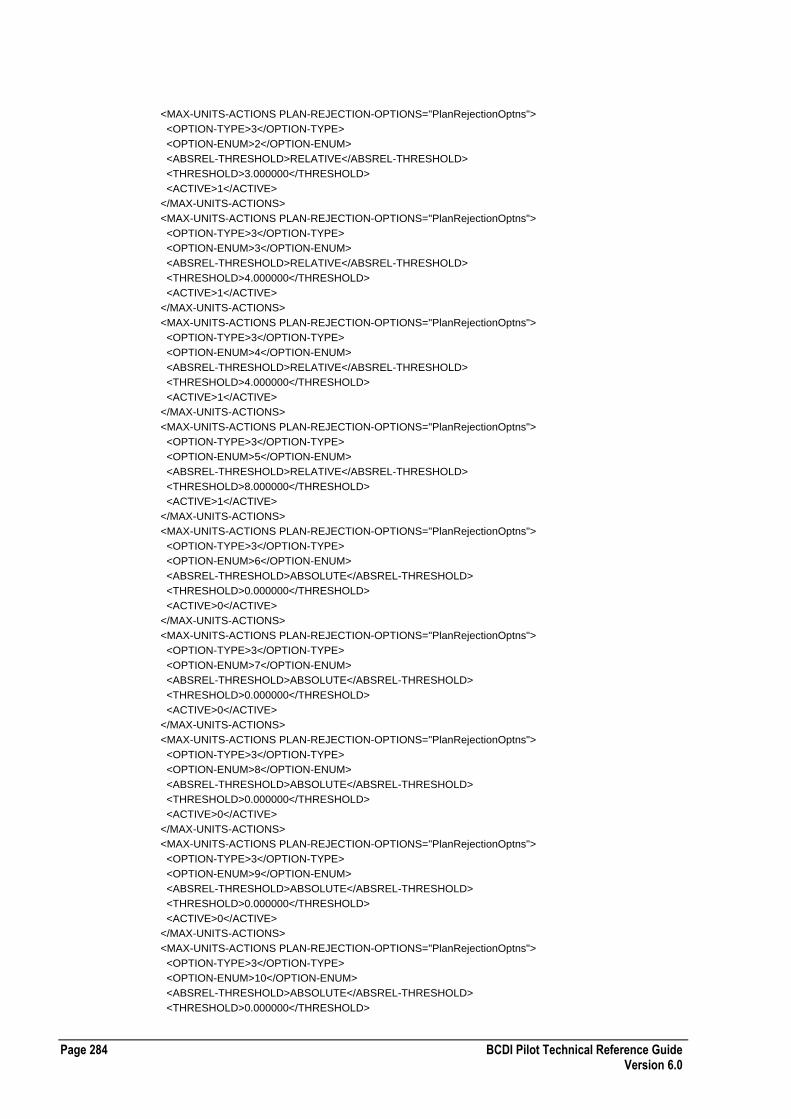
Page 284 BCDI Pilot Technical Reference Guide Version 6.0
<MAX-UNITS-ACTIONS PLAN-REJECTION-OPTIONS="PlanRejectionOptns">
<OPTION-TYPE>3</OPTION-TYPE>
<OPTION-ENUM>2</OPTION-ENUM>
<ABSREL-THRESHOLD>RELATIVE</ABSREL-THRESHOLD>
<THRESHOLD>3.000000</THRESHOLD>
<ACTIVE>1</ACTIVE>
</MAX-UNITS-ACTIONS>
<MAX-UNITS-ACTIONS PLAN-REJECTION-OPTIONS="PlanRejectionOptns">
<OPTION-TYPE>3</OPTION-TYPE>
<OPTION-ENUM>3</OPTION-ENUM>
<ABSREL-THRESHOLD>RELATIVE</ABSREL-THRESHOLD>
<THRESHOLD>4.000000</THRESHOLD>
<ACTIVE>1</ACTIVE>
</MAX-UNITS-ACTIONS>
<MAX-UNITS-ACTIONS PLAN-REJECTION-OPTIONS="PlanRejectionOptns">
<OPTION-TYPE>3</OPTION-TYPE>
<OPTION-ENUM>4</OPTION-ENUM>
<ABSREL-THRESHOLD>RELATIVE</ABSREL-THRESHOLD>
<THRESHOLD>4.000000</THRESHOLD>
<ACTIVE>1</ACTIVE>
</MAX-UNITS-ACTIONS>
<MAX-UNITS-ACTIONS PLAN-REJECTION-OPTIONS="PlanRejectionOptns">
<OPTION-TYPE>3</OPTION-TYPE>
<OPTION-ENUM>5</OPTION-ENUM>
<ABSREL-THRESHOLD>RELATIVE</ABSREL-THRESHOLD>
<THRESHOLD>8.000000</THRESHOLD>
<ACTIVE>1</ACTIVE>
</MAX-UNITS-ACTIONS>
<MAX-UNITS-ACTIONS PLAN-REJECTION-OPTIONS="PlanRejectionOptns">
<OPTION-TYPE>3</OPTION-TYPE>
<OPTION-ENUM>6</OPTION-ENUM>
<ABSREL-THRESHOLD>ABSOLUTE</ABSREL-THRESHOLD>
<THRESHOLD>0.000000</THRESHOLD>
<ACTIVE>0</ACTIVE>
</MAX-UNITS-ACTIONS>
<MAX-UNITS-ACTIONS PLAN-REJECTION-OPTIONS="PlanRejectionOptns">
<OPTION-TYPE>3</OPTION-TYPE>
<OPTION-ENUM>7</OPTION-ENUM>
<ABSREL-THRESHOLD>ABSOLUTE</ABSREL-THRESHOLD>
<THRESHOLD>0.000000</THRESHOLD>
<ACTIVE>0</ACTIVE>
</MAX-UNITS-ACTIONS>
<MAX-UNITS-ACTIONS PLAN-REJECTION-OPTIONS="PlanRejectionOptns">
<OPTION-TYPE>3</OPTION-TYPE>
<OPTION-ENUM>8</OPTION-ENUM>
<ABSREL-THRESHOLD>ABSOLUTE</ABSREL-THRESHOLD>
<THRESHOLD>0.000000</THRESHOLD>
<ACTIVE>0</ACTIVE>
</MAX-UNITS-ACTIONS>
<MAX-UNITS-ACTIONS PLAN-REJECTION-OPTIONS="PlanRejectionOptns">
<OPTION-TYPE>3</OPTION-TYPE>
<OPTION-ENUM>9</OPTION-ENUM>
<ABSREL-THRESHOLD>ABSOLUTE</ABSREL-THRESHOLD>
<THRESHOLD>0.000000</THRESHOLD>
<ACTIVE>0</ACTIVE>
</MAX-UNITS-ACTIONS>
<MAX-UNITS-ACTIONS PLAN-REJECTION-OPTIONS="PlanRejectionOptns">
<OPTION-TYPE>3</OPTION-TYPE>
<OPTION-ENUM>10</OPTION-ENUM>
<ABSREL-THRESHOLD>ABSOLUTE</ABSREL-THRESHOLD>
<THRESHOLD>0.000000</THRESHOLD>
BCDI Pilot Technical Reference Guide Page 285 Version 6.0
<ACTIVE>0</ACTIVE>
</MAX-UNITS-ACTIONS>
<MAX-UNITS-ACTIONS PLAN-REJECTION-OPTIONS="PlanRejectionOptns">
<OPTION-TYPE>3</OPTION-TYPE>
<OPTION-ENUM>11</OPTION-ENUM>
<ABSREL-THRESHOLD>ABSOLUTE</ABSREL-THRESHOLD>
<THRESHOLD>0.000000</THRESHOLD>
<ACTIVE>0</ACTIVE>
</MAX-UNITS-ACTIONS>
<MAX-UNITS-ACTIONS PLAN-REJECTION-OPTIONS="PlanRejectionOptns">
<OPTION-TYPE>3</OPTION-TYPE>
<OPTION-ENUM>12</OPTION-ENUM>
<ABSREL-THRESHOLD>ABSOLUTE</ABSREL-THRESHOLD>
<THRESHOLD>0.000000</THRESHOLD>
<ACTIVE>0</ACTIVE>
</MAX-UNITS-ACTIONS>
<MAX-UNITS-ACTIONS PLAN-REJECTION-OPTIONS="PlanRejectionOptns">
<OPTION-TYPE>3</OPTION-TYPE>
<OPTION-ENUM>13</OPTION-ENUM>
<ABSREL-THRESHOLD>ABSOLUTE</ABSREL-THRESHOLD>
<THRESHOLD>0.000000</THRESHOLD>
<ACTIVE>0</ACTIVE>
</MAX-UNITS-ACTIONS>
<MAX-UNITS-ACTIONS PLAN-REJECTION-OPTIONS="PlanRejectionOptns">
<OPTION-TYPE>3</OPTION-TYPE>
<OPTION-ENUM>14</OPTION-ENUM>
<ABSREL-THRESHOLD>ABSOLUTE</ABSREL-THRESHOLD>
<THRESHOLD>0.000000</THRESHOLD>
<ACTIVE>0</ACTIVE>
</MAX-UNITS-ACTIONS>
<MAX-UNITS-ACTIONS PLAN-REJECTION-OPTIONS="PlanRejectionOptns">
<OPTION-TYPE>3</OPTION-TYPE>
<OPTION-ENUM>15</OPTION-ENUM>
<ABSREL-THRESHOLD>ABSOLUTE</ABSREL-THRESHOLD>
<THRESHOLD>0.000000</THRESHOLD>
<ACTIVE>0</ACTIVE>
</MAX-UNITS-ACTIONS>
<MAX-UNITS-ACTIONS PLAN-REJECTION-OPTIONS="PlanRejectionOptns">
<OPTION-TYPE>3</OPTION-TYPE>
<OPTION-ENUM>16</OPTION-ENUM>
<ABSREL-THRESHOLD>ABSOLUTE</ABSREL-THRESHOLD>
<THRESHOLD>0.000000</THRESHOLD>
<ACTIVE>0</ACTIVE>
</MAX-UNITS-ACTIONS>
<MAX-UNITS-ACTIONS PLAN-REJECTION-OPTIONS="PlanRejectionOptns">
<OPTION-TYPE>3</OPTION-TYPE>
<OPTION-ENUM>17</OPTION-ENUM>
<ABSREL-THRESHOLD>ABSOLUTE</ABSREL-THRESHOLD>
<THRESHOLD>0.000000</THRESHOLD>
<ACTIVE>0</ACTIVE>
</MAX-UNITS-ACTIONS>
<MAX-UNITS-ACTIONS PLAN-REJECTION-OPTIONS="PlanRejectionOptns">
<OPTION-TYPE>3</OPTION-TYPE>
<OPTION-ENUM>18</OPTION-ENUM>
<ABSREL-THRESHOLD>ABSOLUTE</ABSREL-THRESHOLD>
<THRESHOLD>0.000000</THRESHOLD>
<ACTIVE>0</ACTIVE>
</MAX-UNITS-ACTIONS>
<MAX-UNITS-ACTIONS PLAN-REJECTION-OPTIONS="PlanRejectionOptns">
<OPTION-TYPE>3</OPTION-TYPE>
<OPTION-ENUM>19</OPTION-ENUM>

Page 286 BCDI Pilot Technical Reference Guide Version 6.0
<ABSREL-THRESHOLD>ABSOLUTE</ABSREL-THRESHOLD>
<THRESHOLD>0.000000</THRESHOLD>
<ACTIVE>0</ACTIVE>
</MAX-UNITS-ACTIONS>
<MAX-UNITS-ACTIONS PLAN-REJECTION-OPTIONS="PlanRejectionOptns">
<OPTION-TYPE>3</OPTION-TYPE>
<OPTION-ENUM>20</OPTION-ENUM>
<ABSREL-THRESHOLD>ABSOLUTE</ABSREL-THRESHOLD>
<THRESHOLD>0.000000</THRESHOLD>
<ACTIVE>0</ACTIVE>
</MAX-UNITS-ACTIONS>
<MAX-UNITS-ACTIONS PLAN-REJECTION-OPTIONS="PlanRejectionOptns">
<OPTION-TYPE>3</OPTION-TYPE>
<OPTION-ENUM>21</OPTION-ENUM>
<ABSREL-THRESHOLD>ABSOLUTE</ABSREL-THRESHOLD>
<THRESHOLD>0.000000</THRESHOLD>
<ACTIVE>0</ACTIVE>
</MAX-UNITS-ACTIONS>
<MAX-UNITS-ACTIONS PLAN-REJECTION-OPTIONS="PlanRejectionOptns">
<OPTION-TYPE>3</OPTION-TYPE>
<OPTION-ENUM>22</OPTION-ENUM>
<ABSREL-THRESHOLD>ABSOLUTE</ABSREL-THRESHOLD>
<THRESHOLD>0.000000</THRESHOLD>
<ACTIVE>0</ACTIVE>
</MAX-UNITS-ACTIONS>
<MAX-UNITS-ACTIONS PLAN-REJECTION-OPTIONS="PlanRejectionOptns">
<OPTION-TYPE>3</OPTION-TYPE>
<OPTION-ENUM>23</OPTION-ENUM>
<ABSREL-THRESHOLD>ABSOLUTE</ABSREL-THRESHOLD>
<THRESHOLD>0.000000</THRESHOLD>
<ACTIVE>0</ACTIVE>
</MAX-UNITS-ACTIONS>
<MAX-UNITS-ACTIONS PLAN-REJECTION-OPTIONS="PlanRejectionOptns">
<OPTION-TYPE>3</OPTION-TYPE>
<OPTION-ENUM>24</OPTION-ENUM>
<ABSREL-THRESHOLD>ABSOLUTE</ABSREL-THRESHOLD>
<THRESHOLD>0.000000</THRESHOLD>
<ACTIVE>0</ACTIVE>
</MAX-UNITS-ACTIONS>
<MAX-UNITS-ACTIONS PLAN-REJECTION-OPTIONS="PlanRejectionOptns">
<OPTION-TYPE>3</OPTION-TYPE>
<OPTION-ENUM>25</OPTION-ENUM>
<ABSREL-THRESHOLD>ABSOLUTE</ABSREL-THRESHOLD>
<THRESHOLD>0.000000</THRESHOLD>
<ACTIVE>0</ACTIVE>
</MAX-UNITS-ACTIONS>
</PLAN-REJECTION-OPTIONS-LIST>

BCDI Pilot Technical Reference Guide Page 287 Version 6.0
Miscellaneous Vendor File Formats
This appendix contains information on the miscellaneous vendor formats that can be used in BCDI Pilot.
Important : Except where otherwise mentioned, spaces in text files are treated as delimiters. Therefore, if you have spaces within names of models, antennas, carrier layers and so on, you need to remove them. It is recommended that you replace them with underscores or run the words together, for example, Flat Terrain becomes FlatTerrain. This may mean temporarily changing your existing BCDI Pilot names so that items will match those from the import file. After a successful import, you can change the names back again.
Warning : If an export is made from a database that uses spaces, it will not be possible to import without editing the file manually.
In This Section
Antenna Diagram File Format 287 Miscellaneous Vendors Carriers File Format 289 Carrier Types Database File Formats 292 Miscellaneous Vendors Exceptions File Format 293 Miscellaneous Vendors Neighbours File Format 294 Miscellaneous Vendors Site Database File Format 296
Antenna Diagram File Format
BCDI Pilot must first import antenna diagrams before they can be used within the application. A header section begins the antenna file that must contain at a minimum the antenna name field. The complete list of fields is given below:
Field Description
NAME Antenna name
MAKE Make / manufacturer
FREQUENCY Frequency (MHz)
H_WIDTH Horizontal beamwidth (degrees)
V_WIDTH Vertical beamwidth (degrees)
A P P E N D I X D
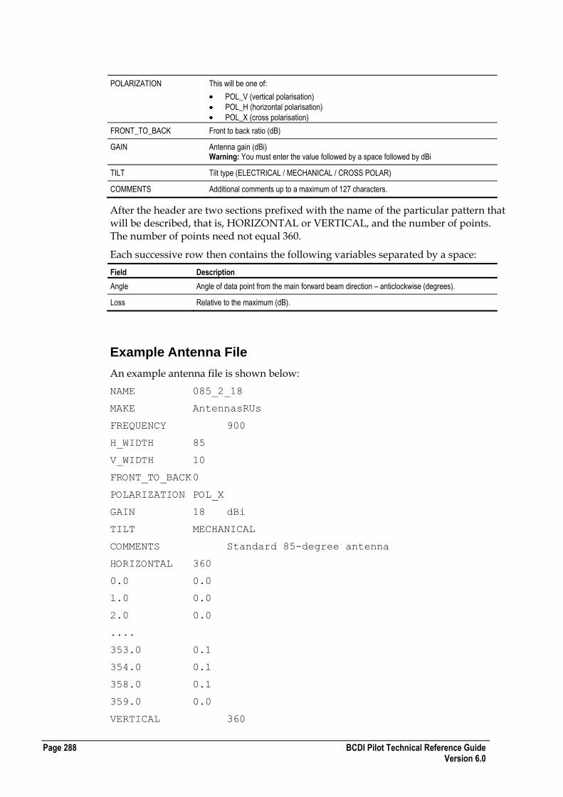
Page 288 BCDI Pilot Technical Reference Guide Version 6.0
POLARIZATION This will be one of:
POL_V (vertical polarisation)
POL_H (horizontal polarisation)
POL_X (cross polarisation)
FRONT_TO_BACK Front to back ratio (dB)
GAIN Antenna gain (dBi) Warning: You must enter the value followed by a space followed by dBi
TILT Tilt type (ELECTRICAL / MECHANICAL / CROSS POLAR)
COMMENTS Additional comments up to a maximum of 127 characters.
After the header are two sections prefixed with the name of the particular pattern that will be described, that is, HORIZONTAL or VERTICAL, and the number of points. The number of points need not equal 360.
Each successive row then contains the following variables separated by a space:
Field Description
Angle Angle of data point from the main forward beam direction – anticlockwise (degrees).
Loss Relative to the maximum (dB).
Example Antenna File
An example antenna file is shown below:
NAME 085_2_18
MAKE AntennasRUs
FREQUENCY 900
H_WIDTH 85
V_WIDTH 10
FRONT_TO_BACK 0
POLARIZATION POL_X
GAIN 18 dBi
TILT MECHANICAL
COMMENTS Standard 85-degree antenna
HORIZONTAL 360
0.0 0.0
1.0 0.0
2.0 0.0
....
353.0 0.1
354.0 0.1
358.0 0.1
359.0 0.0
VERTICAL 360

BCDI Pilot Technical Reference Guide Page 289 Version 6.0
0.0 0.4
1.0 0.0
3.0 1.1
...
355.0 25.4
356.0 16.5
359.0 2.3
The final row is terminated by a carriage return. No additional data should be present after the pattern section, as this will be ignored.
Miscellaneous Vendors Carriers File Format
BCDI Pilot can import and export EET R2C / Planet 2.5, 2.6, 2.7 and 2.8 GSM carrier databases.
The file formats described here are version 2.8.
The Carriers file is in a simple ASCII space-delimited text format.
EET/Planet AMPS Carriers File Format
For AMPS, the EET/Planet Carriers file contains the following fields. The first three fields are tab-separated and the remaining fields are separated by spaces:
Field Data Type Description
Site ID CHAR Alphanumeric site identity. This must be the same as the site ID in the Site Database file.
This should be followed by a tab.
Sector INT Number representing sector (or GSM cell) for cell site.
This should be followed by a tab.
Number of Carriers Allocated INT Number of carriers allocated (maximum of 80 per cell).
This should be followed by a tab.
Carrier1, Carrier2, and so on INT Space-separated list of channel numbers.
Number of Carriers Required INT Number of carriers required for that sector.
Cell ID CHAR Alphanumeric cell identity.
Cntrl INT Control.
DCC INT Signal Digital Colour Code.
- - Not used, a - must be placed here.
Cell INT Cell identifier. Used only if Sector = 1.
If not used, a - must be placed here.
MSC STRING Mobile Switching Centre (up to 16 characters).
Used only if Sector = 1.
If not used, a - must be placed here.

Page 290 BCDI Pilot Technical Reference Guide Version 6.0
Field Data Type Description
UDCP CHAR Two character field for the user-defined character plot.
Not used, a - must be placed here.
Carrier Type1, Carrier Type2, and so on
CHAR Space separated list of carrier types (one per allocated channel).
Number of Carrier Type Demands INT The number of carrier types demanded.
Carrier Type1, Demand, Carrier Type2, Demand, and so on
CHAR and INT Space separated list of carrier type name and carrier type demanded.
Note : The site database files do not export any values in the CELLINFO line other than a set of default values.
Example EET/Planet AMPS Carriers File
The following shows an example EET/Planet AMPS carriers file:
123 1 3 100 104 108 6 - - 1 2 3 - 121 45 - TCH1 TCH1
TCH2 2 TCH1 3 TCH2 1
123 2 6 114 118 122 126 130 134 6 - - 2 3 - - - TCH1
TCH1 TCH2 TCH2 TCH1 TCH1 1 TCH1 3
123 3 2 130 134 6 - - 2 3 - - - TCH1 TCH2 2 TCH1 3 TCH2
2
EET/Planet GSM Carriers File Format
For GSM, the EET/Planet Carriers file contains these fields. The first three fields are tab-separated and the remaining fields are separated by spaces.
Field Data Type Description
Site ID CHAR Alphanumeric site identity. This must be the same as the site ID in the Site Database file.
This should be followed by a tab.
Sector INT Number representing sector (or GSM cell) for cell site.
This can be 0.
This should be followed by a tab.
Number of Carriers Allocated INT Number of carriers allocated (maximum of 80 per cell).
This should be followed by a tab.
Carrier1, Carrier2, and so on INT Space separated list of channel numbers.
Number of Carriers Required INT Number of carriers required for that sector.
LAC INT Location Area Code.
Cell ID CHAR Alphanumeric cell identity.
BCCH INT Broadcast Control Channel.
BSIC INT Base Station Identity Code.
- - Not used, a - must be placed here.
MCC INT Mobile Country Code.
BSC STRING Base Station Controller (up to 6 characters).

BCDI Pilot Technical Reference Guide Page 291 Version 6.0
Field Data Type Description
MSC STRING Mobile Switching Centre (up to 16 characters).
UDCP CHAR This field contains the MNC value.
Carrier Type1, Carrier Type2, and so on
CHAR Space separated list of carrier types (one per allocated channel).
Number of Carrier Type Demands INT The number of carrier types demanded.
Carrier Type1, Demand, Carrier Type2, Demand, and so on
CHAR and INT Space separated list of carrier type name and carrier type demanded.
The site database files do not export any values in the CELLINFO line other than a set of default values.
Example EET/Planet GSM Carriers File
The following shows an example EET/Planet GSM carriers file:
Site1 1 2 6 59 2 13478 Site1A 6 15 - 0 BSC0 MSC0 0
BCCH TCH 2 BCCH 1 TCH 1
Site1 2 1 9 1 13478 Site1B 9 14 - 0 BSC0 MSC0 0 BCCH 2
BCCH 1 TCH 0
Site1 3 1 2 1 13478 Site1C 2 1 - 0 BSC0 MSC0 0 BCCH 2
BCCH 1 TCH 0
Site2 1 1 5 1 13478 Site2A 5 4 - 0 BSC0 MSC0 0 BCCH 2
BCCH 1 TCH 0
Site2 2 2 2 39 2 13478 Site2B 2 1 - 0 BSC0 MSC0 0 BCCH
TCH 2 BCCH 1 TCH 1
Site2 3 2 8 52 2 13478 Site2C 8 2 - 0 BSC0 MSC0 0 BCCH
TCH 2 BCCH 1 TCH 1
Site3 1 2 5 51 2 13478 Site3A 5 3 - 0 BSC0 MSC0 0 BCCH
TCH 2 BCCH 1 TCH 1
Site3 2 2 11 48 2 13478 Site3B 11 7 - 0 BSC0 MSC0 0
BCCH TCH 2 BCCH 1 TCH 1
Site3 3 2 7 58 2 13478 Site3C 7 7 - 0 BSC0 MSC0 0 BCCH
TCH 2 BCCH 1 TCH 1
Site4 1 1 8 1 13478 Site4A 8 1 - 0 BSC0 MSC0 0 BCCH 2
BCCH 1 TCH 0
Site4 2 1 6 1 13478 Site4B 6 12 - 0 BSC0 MSC0 0 BCCH 2
BCCH 1 TCH 0
Site4 3 1 2 1 13478 Site4C 2 17 - 0 BSC0 MSC0 0 BCCH 2
BCCH 1 TCH 0
Site5 1 1 2 1 13478 Site5A 2 13 - 0 BSC0 MSC0 0 BCCH 2
BCCH 1 TCH 0
Site5 2 2 10 49 2 13478 Site5B 10 7 - 0 BSC0 MSC0 0
BCCH TCH 2 BCCH 1 TCH 1
Site5 3 1 4 1 13478 Site5C 4 13 - 0 BSC0 MSC0 0 BCCH 2
BCCH 1 TCH 0

Page 292 BCDI Pilot Technical Reference Guide Version 6.0
Carrier Types Database File Formats
The carrier types database is made up of a number of separate ASCII text files - Carrier Names, Carrier Types and Carrier Groups.
Carrier Names File
The carrier names file, carrier_types.names, holds details of the assignment of names to carriers. An example follows:
HEADER EET V2.7 Carrier Names File. VERSION 1.0
NAME 1
INDEX 1
NAME 1026
INDEX 2
NAME 2
INDEX 3
...
Carrier Types File
The carrier types file, carrier_types.types, holds details of the assignment of carriers to types. An example follows:
HEADER EET V2.7 Carrier Types File. VERSION 1.0
NAME cntrl
SYMBOL +
MAX_ALLOCATION 1
REQUIRED 5
CARRIER 1
CARRIER 1025
CARRIER 2
CARRIER 1026
...
NAME tch
SYMBOL -
MAX_ALLOCATION 0
REQUIRED 15
CARRIER 1
CARRIER 1025
CARRIER 2
CARRIER 1026
...
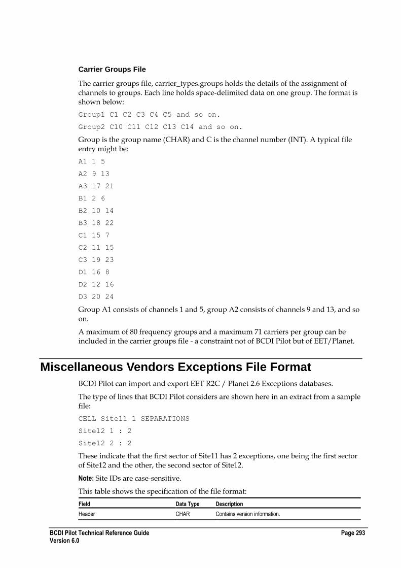
BCDI Pilot Technical Reference Guide Page 293 Version 6.0
Carrier Groups File
The carrier groups file, carrier_types.groups holds the details of the assignment of channels to groups. Each line holds space-delimited data on one group. The format is shown below:
Group1 C1 C2 C3 C4 C5 and so on.
Group2 C10 C11 C12 C13 C14 and so on.
Group is the group name (CHAR) and C is the channel number (INT). A typical file entry might be:
A1 1 5
A2 9 13
A3 17 21
B1 2 6
B2 10 14
B3 18 22
C1 15 7
C2 11 15
C3 19 23
D1 16 8
D2 12 16
D3 20 24
Group A1 consists of channels 1 and 5, group A2 consists of channels 9 and 13, and so on.
A maximum of 80 frequency groups and a maximum 71 carriers per group can be included in the carrier groups file - a constraint not of BCDI Pilot but of EET/Planet.
Miscellaneous Vendors Exceptions File Format
BCDI Pilot can import and export EET R2C / Planet 2.6 Exceptions databases.
The type of lines that BCDI Pilot considers are shown here in an extract from a sample file:
CELL Site11 1 SEPARATIONS
Site12 1 : 2
Site12 2 : 2
These indicate that the first sector of Site11 has 2 exceptions, one being the first sector of Site12 and the other, the second sector of Site12.
Note: Site IDs are case-sensitive.
This table shows the specification of the file format:
Field Data Type Description
Header CHAR Contains version information.
Page 294 BCDI Pilot Technical Reference Guide Version 6.0
Field Data Type Description
Optimise_Which INT Which threshold to optimise on (only used by optimising algorithms).
0=Absolute Area, 1=Percent Area, 2=Percent Traffic
CARRIER_TYPE CHAR Carrier type identity.
CARRIER_TYPE COST_FACTOR FLOAT Indicates that the following lines are a list of carrier types and their associated cost factor.
Thresholds
Thresholds on the preceding CARRIER_TYPE for:
Field Data Type Description
Absolute Area FLOAT Absolute affected area in km².
Percent Area FLOAT Percent affected area.
Absolute Traffic FLOAT Absolute affected traffic in mE.
Percent Traffic FLOAT Percent affected traffic.
Spacings
Minimum channel spacings on the preceding CARRIER_TYPE for:
Field Data Type Description
Min_Chan_Spacing_Site FLOAT Site
Min_Chan_Spacing_Cell FLOAT Cell
Min_Chan_Spacing_Neighbour FLOAT Neighbour Sites
Min_Chan_Spacing_Neighbour2 FLOAT 2nd Order Neighbours
CELL CHAR Site Identity
CELL COST_FACTOR FLOAT Indicates that the following line contains a cost factor for CELL.
GLOBAL ILLEGAL CHANNELS FLOAT Indicates that the following line contains a list of channels that may not be used anywhere on the network.
SEPARATIONS CHAR Indicates that the following lines are a list of cells and separations for the preceding CELL (* means the separation overrides all others).
ILLEGAL CHANNELS CHAR Indicates that the following line is a space-separated list of illegal channels for the preceding CELL.
BORDER RESTRICTIONS CHAR Indicates that the following line is a space-separated list of country borders whose channel restrictions apply to the preceding CELL.
Miscellaneous Vendors Neighbours File Format
BCDI Pilot can import from and export to EET R2C / Planet 2.5, 2.6, 2.7 and 2.8 GSM neighbour files, the specification of these files is as follows.
This is a simple ASCII space separated text format and consists of the following distinct sections - Threshold, Cell, Neighbour, Add and Delete.
BCDI Pilot Technical Reference Guide Page 295 Version 6.0
Threshold and Cell
This table describes the format of the Threshold and Cell sections:
Field Data Type Description
THRESHOLDS INT Four integer fields representing Max Neighbours, Min Neighbours, Min Border Squares and Min Border Percent respectively.
CELL CHAR “CELL” indicates that the Site ID following is the serving cell.
Site ID CHAR Unique identifier for the site.
Sector (cell) INT Sector number.
BSIC INT Not used.
BCCH INT Not used.
HO RxLev INT Not used.
Number of Neighbours INT Number of neighbours following in the file.
Neighbour
This table describes the format of the Neighbour section:
Field Data Type Description
NBR CHAR “NBR” indicates that the Site ID is the neighbour of the last serving cell.
Site ID CHAR Unique identifier for the site.
Sector (cell) INT Sector number.
HO Margin INT Handover Margin
HO RxLev Min INT The minimum handover receiver level.
Max Distance INT Not used.
RxQual INT Not used.
Add and Delete
This table describes the format of the Add and Delete sections:
Field Description
Added Lists cells added manually to the neighbour list. Other fields as previously described.
Deleted Lists cells deleted manually to the neighbour list. Other fields as previously described.
Example Neighbours File
A truncated sample neighbours file for EET/Planet is shown here:
THRESHOLDS 10 3 10 5
CELL XY001 1 0 0 0 3
NBR XY001 3 0 -120 100000 0
NBR XY001b 1 0 -120 100000 0
NBR XY011 2 0 -120 100000 0
Page 296 BCDI Pilot Technical Reference Guide Version 6.0
CELL XY001 2 0 0 0 3
NBR XY001b 2 0 -120 100000 0
NBR XY011 2 0 -120 100000 0
NBR XY006c 2 0 -120 100000 0
ADDED
CELL XY001 1 0 0 0 2
NBR XY002 2 0 -120 100000 0
NBR XY002c 2 0 -120 100000 0
CELL XY001 2 0 0 0 1
NBR XY001b 1 0 -120 100000 0
DELETED
CELL XY019 1 0 0 0 7
NBR XY017h 1 0 -120 100000 0
NBR XY019h 1 0 -120 100000 0
NBR XY019h 2 0 -120 100000 0
NBR XY019h 3 0 -120 100000 0
NBR XY036 1 0 -120 100000 0
NBR XY036 2 0 -120 100000 0
NBR XY036 3 0 -120 100000 0
Miscellaneous Vendors Site Database File Format
BCDI Pilot can import and export the EET R2C / Planet 2.5, 2.6, 2.7 and 2.8 simple text site database file format. The specification of these files is as shown in the tables in this section.
An example of a Planet 2.8 site database file is:
V2.8 Site Database written on Mon Nov 22 13:42:38 1999
SITE_FORMAT EiRP : Do not delete this line
SECTOR_FORMAT : Do not delete this line
CELL_INFO_FORMAT : Do not delete this line
SITE 15A -61.713401 30.192341 7 2 1 6 0 4.21 0 3 Long Bridgeÿÿ
SECTOR 40 55 0.0 60_Sector_PCS_Dapa_DP59200 48.77 URBAN
CELLINFO RBS2201 Non-Balanced 0.00 0.00 0.00 0.00 0.00 0.00
0.00 0.00 35.00
SECTOR 160 55.20 0.0 60_Sector_PCS_Comsat_PCSA090190 48.77
URBAN
CELLINFO RBS2201 Non-Balanced 0.00 0.00 0.00 0.00 0.00 0.00
0.00 0.00 35.00
SECTOR 280 55.32 0.0 60_Sector_PCS_Dapa_DP59200 48.77 URBAN
BCDI Pilot Technical Reference Guide Page 297 Version 6.0
CELLINFO RBS2201 Non-Balanced 0.00 0.00 0.00 0.00 0.00 0.00
0.00 0.00 35.00
Planet 2.5 Site Database Format
The Planet version 2.5 site database file is in a simple ASCII tab-separated text format, designed to be easy to use in Microsoft Excel, and for easy conversion to and from other formats.
All data pertaining to a particular site is on the same line in the file.
Site Data Record (1 per Site)
The site data record is:
Field Data Type Description
Site ID char[32] Site Identifier
Easting / Longitude float The x co-ordinate of the site (metres or decimal degrees).
Northing / Latitude float The y co-ordinate of the site (metres or decimal degrees).
Site Status flags integer [5] Numeric representation of the site status flags.
Note : If you do not have any status flags, you will have 5 zeros in the file.
Ground Height float Ground height in metres above sea level (0 indicates that DTM map data value is to be used).
Antenna Height float Antenna height in metres above ground level (one value for all sectors).
Hex Radius Flag integer 0 gives default value.
Sector Count integer Number of sectors.
Model Name char[32] Propagation model (no spaces allowed) – one per site.
Sector Data Record (1 per Sector)
The number of sector data records is determined by the Sector Count value in the site data record. The sector data record is:
Field Data Type Description
Azimuth float Direction of sector main beam (degrees).
Power float EiRP of sector (dBm).
Tilt float Downtilt of sector (degrees) - positive value indicates downtilt.
Antenna Name char[32] Type of antenna (no spaces allowed).
Site name (1 per Site)
The site name is:
Field Data Type Description
Site Name char[32] Name of site. This can contain spaces but cannot contain other characters such as commas.
Planet 2.8 Site Database File Format Header Records
One of each of the following records per file:

Page 298 BCDI Pilot Technical Reference Guide Version 6.0
The Version record format is:
Field Data Type Description
Version Identifier CHAR Identifies the version of EET that was used to store the database. For version 2.8 this is “V2.8”.
Optional Message CHAR The time and date that the database was last stored.
The Site Data record format is:
Field Data Type Description
Site Format CHAR ERP or EiRP
Note : The Sector Data and Cell Data record formats are not used by BCDI Pilot but must exist in file.
Planet 2.8 Site Database File Format Data Records
One Site Data Record per site:
Field Data Type Description
Keyword CHAR[4] “SITE” identifies the record.
Site ID CHAR[11] Unique identifier for the site.
Easting/Longitude FLOAT The x co-ordinate of the site (metres or decimal degrees).
Northing/Latitude FLOAT The y co-ordinate of the site (metres or decimal degrees).
Site Status Flags INT[5] Numeric representation of the site status flags.
Ground Height FLOAT The height of the site above mean sea level (metres).
Hexagon Flag INT Numeric representation of the hexagon radius and type.
Site Type Flag INT A decimal number of up to three digits that has the site type and number of sectors encoded into it, as follows:
N = Number of Sectors (N in range 1 to 6)
-0- = Macrocell
-3- = Microcell
1-- = Repeater Site
Site Name CHAR[23] Because this is an optional string that can contain anything (including spaces), the delimiter is a special character ÿ.
The ASCII code for this is 255.
Site Name 2 CHAR[23] Because this is an optional string that can contain anything (including spaces), the delimiter is a special character ÿ.
The ASCII code for this is 255.
Narrative CHAR[80]
Sector Data Record
One per sector of every site:
Field Data Type Description
Keyword CHAR[6] “SECTOR” identifies this record.
Alignment FLOAT Angle from North of sector (degrees).
Power FLOAT ERP or EiRP of sector (dBm) depending on the value of the Site Format field in the Header Record. All power values should be consistent (all ERP or all EiRP).

BCDI Pilot Technical Reference Guide Page 299 Version 6.0
Field Data Type Description
Tilt FLOAT Downtilt of sector (degrees).
Antenna Name CHAR[99] Name of antenna (no spaces allowed).
Antenna Height FLOAT Height of antenna above ground (metres).
Model Name CHAR[31] Name of propagation model (no spaces allowed).
Cell Data Record
One per sector of every site.
Field Data Type Description
Keyword CHAR[8] “CELLINFO” identifies the start of the cell information details.
Equipment Type CHAR[21] The equipment type the cell uses.
Balanced Mobile CHAR[21] Mobile / CE type the cell is presently balanced for. If the cell is not balanced then defaults to non-balanced.
Equipment Loss FLOAT Sum of all the downlink losses / gains from the presently selected cell equipment.
Output Power FLOAT Do not change from zero.
Uplink Feeder Loss FLOAT The feeder loss applicable to the uplink side.
Downlink Feeder Loss FLOAT The feeder loss applicable to the downlink side.
Diversity Gain FLOAT The amount of diversity gain from the cell, if applicable.
Uplink Misc. Loss FLOAT The amount of misc. losses on the uplink side.
Downlink Misc. Loss FLOAT The amount of misc. losses on the downlink side.
Mobile ERP FLOAT The peak power of the mobile/ CE type for which the cell is balanced.
GSM Range FLOAT A user definable range (only applicable in GSM systems). Interference into this cell from other servers will not be considered, because this cell cannot cover beyond this range. However, this cell will still interfere into other cells independent of the range.

Page 300 BCDI Pilot Technical Reference Guide Version 6.0

BCDI Pilot Technical Reference Guide Page 301 Version 6.0
Antenna and Diffraction Calculations
This section describes the antenna and diffraction calculations that are used throughout the suite of BCDI Pilot products.
Any calculations and algorithms specific to individual products are described in that product's User Reference Guide.
In This Section
Antenna Calculations 301 Diffraction Calculations 309
Antenna Calculations
This section describes the antenna calculations made in the BCDI Pilot suite of products. Additional calculations made by other products are described in that individual product's User Reference Guide.
Calculation of Free Space Loss
The Free Space Loss (FSL) used in antenna algorithms is calculated as follows:
Where:
F is the frequency (MHz)
D is the distance (km)
Calculation of EiRP and ERP
EiRP is calculated as follows:
EiRP = PAPower - cellEquipmentLoss - feederLoss + antennaG + antennaCorrectionFactor + cellCorrection
A P P E N D I X E

Page 302 BCDI Pilot Technical Reference Guide Version 6.0
Where:
feederLoss is (feederLength * feederLossPerMeter) + feederConnectionLoss
antennaG is antennaGain (+ 2.14 if the gain is in dBd)
ERP = EiRP - 2.14
Antenna Tilt and Masking Calculations
This section describes the algorithms used to calculate the loss due to the antenna mask and the effects of mechanical tilt.
Calculation of Antenna Mask in an Arbitrary Direction
Antenna mask information is generally supplied by manufacturers in the form of a simple text file containing measured loss values relative to the maximum gain of the antenna. The measurements are taken on two sets of points lying on circles in two orthogonal planes. The horizontal mask represents a set of loss values taken at the angle of electrical downtilt, that is the angle at which the vertical masking loss is 0 dB. For example, if the vertical masking pattern has its 0 dB loss at a downward angle of 3 degrees, then the horizontal mask represents a set of measurements taken at points at a downward angle of 3 degrees from the antenna.
The two sets of measured loss values provide only a simplistic representation of the actual radiation from the antenna and some interpretation of these measurements is required to estimate the loss at other angles. This is done as follows:
Horizontal and vertical mask patterns and have their losses measured in
dB. The angles (azimuth) and (elevation) are spherical-polar angles measured in
degrees and lying in the ranges and . The vertical
masking pattern has its 0 dB loss at an angle .
A masking-loss function can be constructed that is based on a linear combination of the front and rear ends of the vertical masking pattern, weighted by
the azimuth angle :
This function does not give the correct result on the horizontal plane where
is required . This can be corrected by a simple normalisation as follows:

BCDI Pilot Technical Reference Guide Page 303 Version 6.0
Checking the Properties of Gnorm
For points in the plane of the front vertical mask the correct result is obtained:
since
For points in the plane of the rear vertical mask the correct result is obtained:
since .
For points at the angle of electrical down tilt the correct result is obtained:
.
Calculation of Antenna Mask for Symmetrical and Non-symmetrical Mask Styles
If you are using a microwave antenna defined with a symmetrical mask, it is easy to calculate the loss at any point. To do this:
Take the horizontal and vertical angle of an incoming vector, and calculate the 3-dimensional angle between that vector and the direction vector of the antenna.
This is the same as rotating the mask around its y-axis.
Rotating an antenna around its y-axis

Page 304 BCDI Pilot Technical Reference Guide Version 6.0
Based on this symmetrical antenna mask, the effective 3d pattern would look something like this:
3D Pattern for Symmetrical Antenna Mask
The centre of the graph (from -90 to 90) shows the loss at the front of the antenna and the sides of the graph show the loss at the rear of the antenna.
However, if you are using a microwave antenna defined with non-symmetrical masks, one representing the horizontal plane and one representing the vertical plane, then these must be interpolated to create the 3d mask. This typically happens with sectorised antennas in a point to multi-point system.
The formula used to interpolate these is as follows:
(1)
Where:
is the horizontal masking angle (+ive is clockwise)
is the vertical masking angle (-ive is down)
is the angle of electrical downtilt (where loss is 0.0db)
is the horizontal mask
is the vertical mask
is the interpolated mask
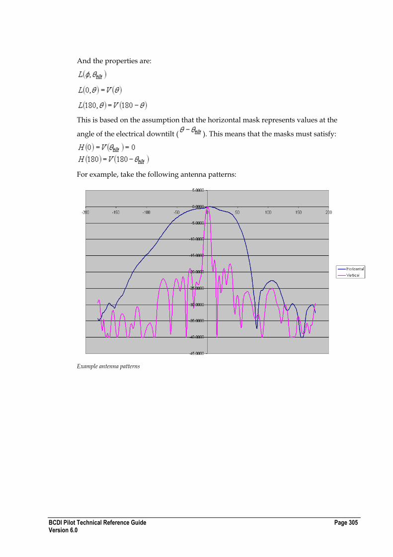
BCDI Pilot Technical Reference Guide Page 305 Version 6.0
And the properties are:
This is based on the assumption that the horizontal mask represents values at the
angle of the electrical downtilt ( ). This means that the masks must satisfy:
For example, take the following antenna patterns:
Example antenna patterns

Page 306 BCDI Pilot Technical Reference Guide Version 6.0
The interpolation would produce the following 3d pattern:
Calculation of Tilted Antennas
To correctly calculate the effects of mechanical tilt, the location of the mobile relative to that of the antenna in terms of both vertical and horizontal planes must be considered. It is assumed that if the antenna is electrically tilted then this effect is already included in the antenna pattern supplied, that is the vertical mask will have a 0 dB loss at some non-zero angle.
Consider a TX antenna at the origin (0, 0, 0) with azimuth angle and downtilt
angle . Let the world co-ordinate system be (x, y, z) where z = height, and the
antenna co-ordinate system ( ). The horizontal and vertical antenna masks
are defined in the and planes respectively.
To define spherical polar co-ordinates (r, , ) for the world co-ordinate system:
(1)

BCDI Pilot Technical Reference Guide Page 307 Version 6.0
and a similar system of spherical polar co-ordinates (r, ) for the antenna co-ordinate system:
(2)
Cartesian co-ordinates in the two systems are related by the following transformation:
(3)
Substituting (1) and (2) into (3) gives expressions relating to as follows:
Thus given a point (x, y, z) in the world co-ordinate system, you can derive the
azimuth and elevation of the point in the antenna co-ordinate system.
Line of Sight and Non Line of Sight Paths
For line of sight paths (LOS), antenna masks are applied based on the elevation ( ) of the RX with respect to the TX.
For non-LOS paths, the masks are applied by considering the elevation ( ) of the diffracting peak closest to the TX. This diagram shows non-LOS tilt calculations:
Non LOS Tilt Calculations

Page 308 BCDI Pilot Technical Reference Guide Version 6.0
Antenna Hopping Calculations
Antenna hopping is a transmit diversity scheme in which consecutive bursts of information are transmitted on different antennas. When antennas are exposed to a different multipath fading, a diversity gain is achieved.
This gain figure is applied to interference calculations in arrays and frequency planning, specifically Worst Connection, Average Connection and LMU C/I arrays.
Antenna Hopping Gain Calculation
The antenna gain ( ) for each subcell is calculated as follows:
)
Where:
is the Frequency Hopping gain
is the number of Frequency Hopping carriers
is the number of antennas used by the subcell, always assumed to be 2
Antenna Hopping Array Calculation
If antenna hopping is enabled in the Array Settings dialog box, then the specified antenna hopping gain figure is applied to the C/I calculations. This changes the C/I calculation to:
Where :
is the Antenna Hopping gain
is the C/I ratio for a frequency (i)
is the signal strength from frequency (i) for the serving cell
is the interfering cell
is the signal strength from frequency (i) for the interfering cell K
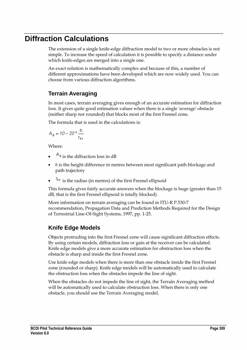
BCDI Pilot Technical Reference Guide Page 309 Version 6.0
Diffraction Calculations
The extension of a single knife-edge diffraction model to two or more obstacles is not simple. To increase the speed of calculation it is possible to specify a distance under which knife-edges are merged into a single one.
An exact solution is mathematically complex and because of this, a number of different approximations have been developed which are now widely used. You can choose from various diffraction algorithms.
Terrain Averaging
In most cases, terrain averaging gives enough of an accurate estimation for diffraction loss. It gives quite good estimation values when there is a single 'average' obstacle (neither sharp nor rounded) that blocks most of the first Fresnel zone.
The formula that is used in the calculations is:
Where:
is the diffraction loss in dB
h is the height difference in metres between most significant path blockage and path trajectory
is the radius (in metres) of the first Fresnel ellipsoid
This formula gives fairly accurate answers when the blockage is huge (greater than 15 dB, that is the first Fresnel ellipsoid is totally blocked).
More information on terrain averaging can be found in ITU-R P.530-7 recommendation, Propagation Data and Prediction Methods Required for the Design of Terrestrial Line-Of-Sight Systems, 1997, pp. 1-25.
Knife Edge Models
Objects protruding into the first Fresnel zone will cause significant diffraction effects. By using certain models, diffraction loss or gain at the receiver can be calculated. Knife edge models give a more accurate estimation for obstruction loss when the obstacle is sharp and inside the first Fresnel zone.
Use knife edge models when there is more than one obstacle inside the first Fresnel zone (rounded or sharp). Knife edge models will be automatically used to calculate the obstruction loss when the obstacles impede the line of sight.
When the obstacles do not impede the line of sight, the Terrain Averaging method will be automatically used to calculate obstruction loss. When there is only one obstacle, you should use the Terrain Averaging model.
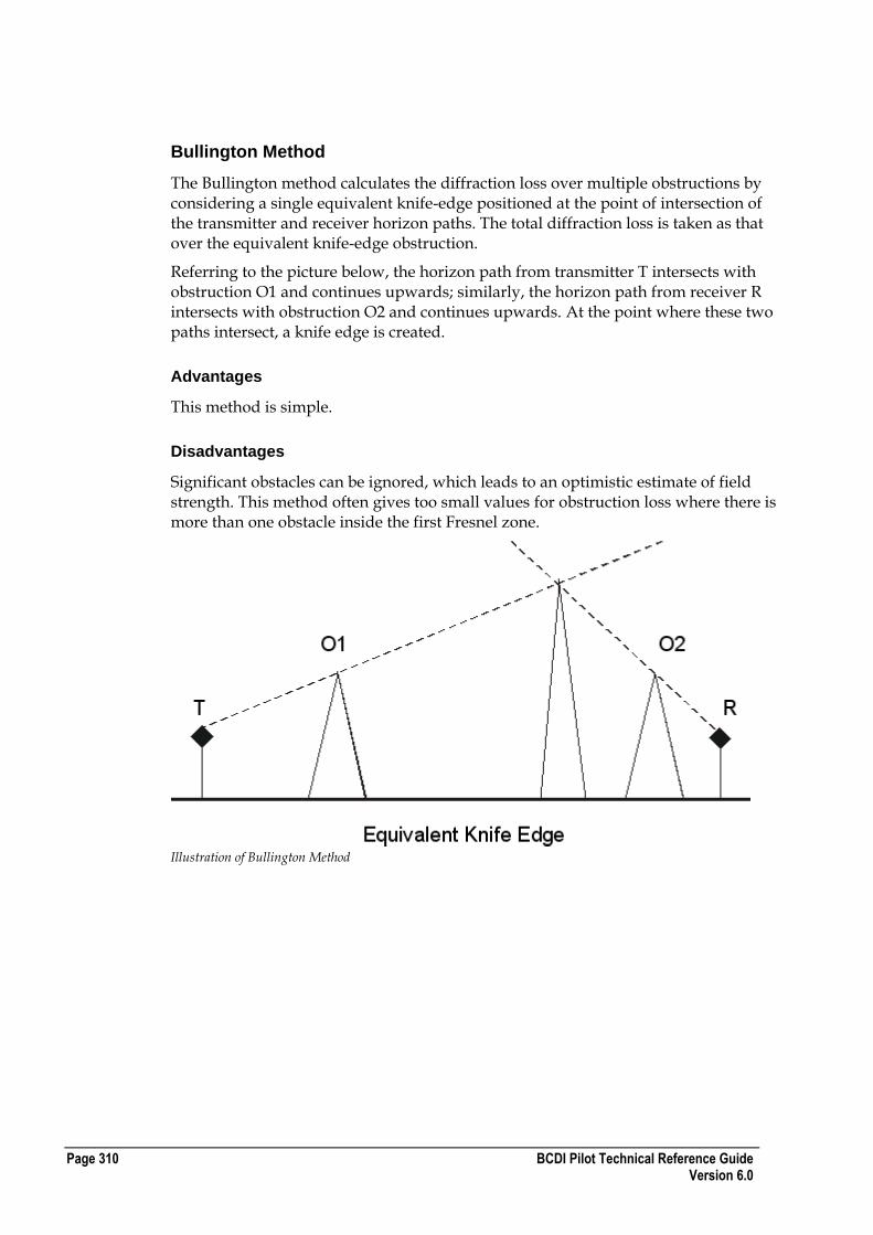
Page 310 BCDI Pilot Technical Reference Guide Version 6.0
Bullington Method
The Bullington method calculates the diffraction loss over multiple obstructions by considering a single equivalent knife-edge positioned at the point of intersection of the transmitter and receiver horizon paths. The total diffraction loss is taken as that over the equivalent knife-edge obstruction.
Referring to the picture below, the horizon path from transmitter T intersects with obstruction O1 and continues upwards; similarly, the horizon path from receiver R intersects with obstruction O2 and continues upwards. At the point where these two paths intersect, a knife edge is created.
Advantages
This method is simple.
Disadvantages
Significant obstacles can be ignored, which leads to an optimistic estimate of field strength. This method often gives too small values for obstruction loss where there is more than one obstacle inside the first Fresnel zone.
Illustration of Bullington Method

BCDI Pilot Technical Reference Guide Page 311 Version 6.0
Epstein-Peterson Method
The Epstein Peterson technique is based on the assumption that the total loss can be evaluated as the sum of attenuation due to each respective significant obstruction.
Referring to the picture below, the diffraction loss from the obstacle is calculated by assuming that the receiver is at the second obstruction (T-O1-O2). The loss from the second obstacle is then calculated assuming the transmitter is at the first obstruction and the receiver at the third (O1-O2-O3). Finally, the loss from a transmitter at the second obstacle to the receiver (O2-O3-R) is calculated. The total Epstein-Peterson diffraction loss is given by the sum of all the losses calculated.
Advantages
This method does not ignore important obstacles in the way that the Bullington method might, but to some extent it still suffers from underestimating the path loss.
When the obstacles are widely separated, this method gives more accurate values than Deygout.
Disadvantages
This method often gives too small values for obstructions loss where there are obstacles close to each other and inside the first Fresnel zone.
Illustration of Epstein-Peterson Method

Page 312 BCDI Pilot Technical Reference Guide Version 6.0
Japanese Atlas Method
Note : This method is not commonly used in trs planning.
The Japanese Atlas technique is similar to the Epstein-Peterson method and was proposed by the Japanese postal service. Again it is based on the assumption that the total loss can be evaluated as the sum of attenuation due to each obstruction. However, in contrast to the Epstein-Peterson method, the effective source is not the top of the preceding obstruction but the projection of the horizon ray for the obstruction to a point on the vertical plane through one of the terminals.
Referring to the diagram, the total loss is given by the sum of losses for T-O1-O2, T‟-O2-O3 and T‟‟-O3-R.
Advantages
This method gives improved results when the obstructions are closely spaced.
Disadvantages
To some extent this method still suffers from underestimating the path loss.
Illustration of Japanese Atlas Method

BCDI Pilot Technical Reference Guide Page 313 Version 6.0
Deygout Method
The Deygout technique calculates a „v-parameter‟ for each edge, the one with the largest is termed the main edge and its loss calculated in the standard way. Additional losses for other obstructions are calculated between the main edge and the obstructed terminal. The total Deygout loss is given by the sum of all losses calculated.
In order to extend the technique to many obstructions, it is necessary to employ sub-main edges. These are the next most significant edges at either side of the main edge. The loss from the sub-main-edge is calculated assuming a hypothetical terminal located at the main-edge (ignoring any less significant edges).
Advantages
This method provides accurate results where there are two obstructions, with one being clearly dominant. For three or four obstructions, the Deygout method gives the best results of any of the approximate methods.
Disadvantages
Where there is no dominant edge, the Deygout method tends to overestimate the loss.
Where there are several equal obstacles inside the first Fresnel zone or close to each other, this method underestimates the obstruction loss.
Illustration of Deygout Method
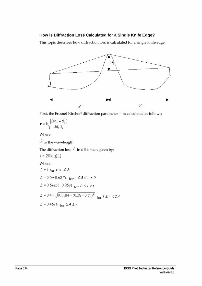
Page 314 BCDI Pilot Technical Reference Guide Version 6.0
How is Diffraction Loss Calculated for a Single Knife Edge?
This topic describes how diffraction loss is calculated for a single knife edge.
First, the Fresnel-Kirchoff diffraction parameter is calculated as follows:
Where:
is the wavelength
The diffraction loss in dB is then given by:
Where:
for
for
for
for
for
BCDI Pilot Technical Reference Guide Page 315 Version 6.0
Index
3
3GPP file formats • 31
A
Aerial photographs • 14 Antennas
calculations • 308 diagrams • 287 example • 288 format • 197, 204, 287 hopping • 308 mask loss algorithms • 302
Arrays file formats • 40, 42 index files • 40
Assignments, carriers • 60
B
Backdrops • 14 Bands
XML format • 196 BCDI Pilot
file formats • 29 Bearers
XML format • 215 BSCs, XML format • 76, 143 BSs, XML format • 144 BTSs
XML format • 199 Bullington diffraction calculations • 309
C
Cabins file format • 199
Calculations diffractions • 309 mask loss • 302 tilt • 302
Carrier layers XML format • 183
Carrier Wave data • 52 Carriers
assignments • 60 file format • 88, 183, 189, 195, 289, 293
Cells equipment • 200 file format • 77, 79, 133, 200
layers • 186 Channels
XML format • 196 Colours, file format • 60 Configuration files, format • 180 Connections
file format • 155 Contacts
XML format • 197 Coverage
formats • 40 importing • 40
CW data file formats • 52
D
Datums exporting • 75
Deygout diffraction calculations • 309 Diffraction Calculation Methods • 309
E
EiRP calculation • 301
Electrical tilt • 302 Epstein Peterson diffraction calculations • 309 Equipment
file format • 193, 200, 210 suppliers • 193
ERP calculation • 301
EV-DO downlink parameters, XML format • 222
Examples antennas • 288 neighbours file • 295 table file • 48
Exporting coverage • 40
F
Favourites file format • 57
Feeders XML format • 200
Fields file format • 58
File formats 3GPP XML • 31 arrays • 40, 42 coverage • 40 ILSA • 60 interference • 40 live traffic for 2g • 64 live traffic for 3g • 65 Simulation arrays • 44 XML • 69, 73
H
Hopping antenna • 308
Page 316 BCDI Pilot Technical Reference Guide Version 6.0
Hubs XML format • 87, 92
I
ILSA file formats • 60
Importing coverage • 40
Index files arrays • 40 backdrops • 18 height • 12 text • 27 vectors • 21, 26
Interconnects, XML format • 90, 92 Interference
tables • 47 Interference tables
file formats • 47
J
Japanese Atlas diffraction calculations • 309
K
Knife Edge diffraction calculations • 309
L
Line of sight masks • 307
Link terminal equipment XML format • 201
Linkends XML format • 99
Links file format • 202
LMUs XML format • 140
Logical nodes • 133
M
Map data format • 11
Maps scanned • 14
Mast head amplifiers XML format • 203
Masts, XML format • 202 MSCs, XML fomat • 75, 143
N
Neighbours file format • 49, 295 XML format • 156
Networks XML format • 126
Networks 3GPP • 31
Node Bs
XML format • 130 Non line of sight
diagram • 307 masks • 307
P
PA Output Calculation of EiRP and ERP • 301
Photographs, file format • 14 PlaNet file formats • 297, 298
AMPS Carriers • 289 GSM Carriers • 290 Site Database (2.5) • 297 Site Database (2.8) • 297, 298
Projections datums • 75
Propagation Models XML format • 180
Properties export • 39 file format • 39 XML format • 74
R
Radiated power, setting • 301 Radio equipment
XML format • 210 Repeaters
XML format • 84 RNCs
XML format • 129 Routes
XML format • 125
S
Scanned maps, configuring • 14 Sectors
XML format • 88, 149 Services
XML format • 219 SGSNs
XML format • 128 Simulated traffic, XML format • 147 Sites
XML format • 77
T
Terminal types XML format • 224
Terrain averaging diffraction calculations • 309 height • 12
Traffic file formats • 50
V
Vectors file formats • 20
BCDI Pilot Technical Reference Guide Page 317 Version 6.0
W
WMSCs, XML format • 127
X
XML editing files • 72 file formats • 73 getting started • 69 importing • 71 index files • 70 special character sets • 73

Page 318 BCDI Pilot Technical Reference Guide Version 6.0