bcc extruded text - boris fxcdn.borisfx.com/borisfx/documentation/bccofx/bccextrudedtext.pdf · bcc...
TRANSCRIPT

BCC Extruded Textquick links ; “Applying the filter”, “Text Window”, “Presets”, “Render Options”, “Extrusion” , “Materials”, “Transfor-mations”, “Path”, “Letter Transformations”, “Built-in Light”, “Built-in Camera”, “Deformers”______________________________
Applying the BCC Extruded Text filter in Sony Vegas
- Apply the BCC Extruded Text filter either as a Video Event FX, Video Track FX or Media FX:
The filter must be applied to an Empty Event inserted over a media clip to preserve alpha. However, when applied as a Media FX it has to be applied to a media clip (which can be inserted in the Empty Event over the original clip if alpha needs to be preserved).
- After applying the filter, it is necessary to click on Launch Text Window button located at the top of the effect’s controls to enter edit text. It is possible to launch the text window to edit text at any time by clicking the “Launch Text Window”:
_____________________________Text Window- BCC Extruded Text uses the standard Boris Text Window (like the Boris Title Toolkit, RED, Blue, and Graffiti products).- The Text Window is where text is entered and formatted, where Font and Point Size are selected, etc.- Smaller point sizes generally do not work well when extruding text - it's best to start with a larger point size (perhaps a point size of 100 or larger depending on the Font) - and then to reduce the size by scaling it down us-ing the Scale controls in the filter's Transformations group if smaller text is desired.- Changes made to most of the attributes in the Text Window (font and point size for example) are applied to the currently selected text – which means it is possible to use multiple fonts and point sizes within the same text object.- It is possible to do pair kerning by placing the cursor between 2 text characters and using the left and right ar-row keys along with the alt modifier key.- When the Text Window is open and text entry, editing, or formatting is finished, the Text Window can be closed by using the Apply or Cancel buttons in the bottom right area of the window or by choosing Close from under the File menu (or keyboard shortcut for Close).

__________________________________
Built in Filter PresetsThere are several levels of built-in preset controls in the Extruded Text filter ;
- There is a master preset control for saving and loading values for all the parameters in the filter. This is the 1st preset control, near the top of the Effect Controls panel:
- There is an Extrusion Style preset control for saving and loading a style that includes all the Extrusion and Material attributes:
- There are 2 preset controls (Bevel and Side) for saving and loading (for use in defining extrusion shapes):

- There are Material preset controls for saving and applying materials used on the extrusion surfaces:
Steps for using some of the specific types of preset loaders will be discussed later in relevant sections of this document, but in general ; the “Load” selection opens a file Open dialogue for navigating to a preset to open it ; the “Save” selection opens a file Save As dialogue for saving new presets.
_________________________________
RenderThe Render parameter group includes controls that can affect the smoothness and edge quality as well as some other options that affect the visual quality of the Extruded Text effect.
- The Polygon Count parameter can be used to increase or decrease the number of polygons defining the ex-truded object. If curved edges or surfaces of the extrusion look blocky, increasing the Polygon Count will result in the curves looking smoother. The performance of the filter is affected by the Polygon Count and it is possible to speed up the performance (during preview or exporting the final effect) by reducing the Polygon Count.
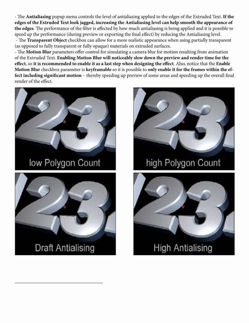
- The Antialiasing popup menu controls the level of antialiasing applied to the edges of the Extruded Text. If the edges of the Extruded Text look jagged, increasing the Antialiasing level can help smooth the appearance of the edges. The performance of the filter is affected by how much antialiasing is being applied and it is possible to speed up the performance (during preview or exporting the final effect) by reducing the Antialiasing level. - The Transparent Object checkbox can allow for a more realistic appearance when using partially transparent (as opposed to fully transparent or fully opaque) materials on extruded surfaces.- The Motion Blur parameters offer control for simulating a camera blur for motion resulting from animation of the Extruded Text. Enabling Motion Blur will noticeably slow down the preview and render time for the effect, so it is recommended to enable it as a last step when designing the effect. Also, notice that the Enable Motion Blur checkbox parameter is keyframable so it is possible to only enable it for the frames within the ef-fect including significant motion – thereby speeding up preview of some areas and speeding up the overall final render of the effect.
____________________________________

ExtrusionThe Extrusion parameter group includes controls for adjusting the shape (geometry) of the extruded text object.
- The Extrusion Depth parameter defines the depth of the side face that extends between the front and back of the extruded text.- The Bevel Style popup menu offers choices for Straight, Convex, Concave or Saved Preset. the Saved Preset choice allows for using a preset created by saving a bevel style.- The Bevel Amount parameter determines the depth of the edge bevels for the extruded text.- The Back Bevels checkbox enables edge bevels between the side and back face of the extruded text.- The Side Style popup menu offers choices of Straight or Saved Preset. The Saved Preset choice allows for using a preset created by saving a side style.- The Bevel Saved Preset and the Side Saved Preset controls are where you can access bevel or side preset styles that have been saved.
____________________________________
Materials
Material parameters are used to determine the appearance of the surface(s) of the Extruded Text.
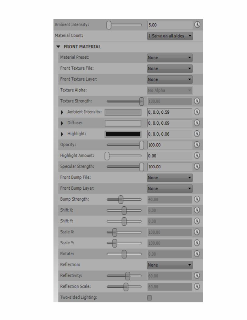
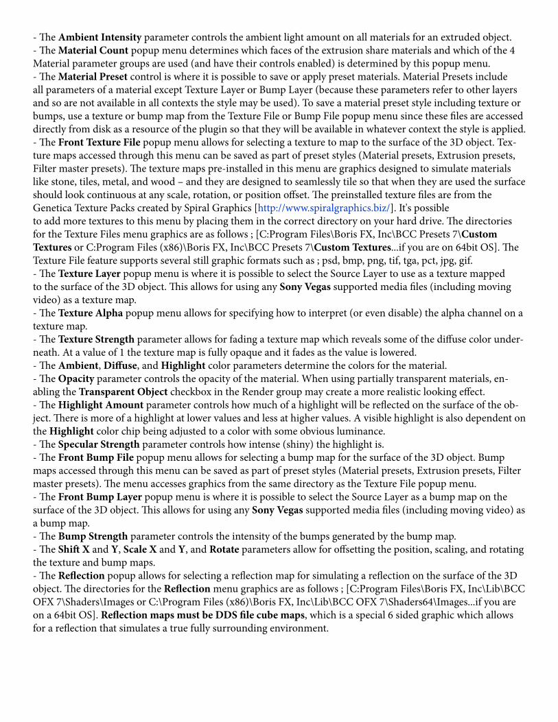
- The Ambient Intensity parameter controls the ambient light amount on all materials for an extruded object.- The Material Count popup menu determines which faces of the extrusion share materials and which of the 4 Material parameter groups are used (and have their controls enabled) is determined by this popup menu.- The Material Preset control is where it is possible to save or apply preset materials. Material Presets include all parameters of a material except Texture Layer or Bump Layer (because these parameters refer to other layers and so are not available in all contexts the style may be used). To save a material preset style including texture or bumps, use a texture or bump map from the Texture File or Bump File popup menu since these files are accessed directly from disk as a resource of the plugin so that they will be available in whatever context the style is applied.- The Front Texture File popup menu allows for selecting a texture to map to the surface of the 3D object. Tex-ture maps accessed through this menu can be saved as part of preset styles (Material presets, Extrusion presets, Filter master presets). The texture maps pre-installed in this menu are graphics designed to simulate materials like stone, tiles, metal, and wood – and they are designed to seamlessly tile so that when they are used the surface should look continuous at any scale, rotation, or position offset. The preinstalled texture files are from the Genetica Texture Packs created by Spiral Graphics [http://www.spiralgraphics.biz/]. It's possibleto add more textures to this menu by placing them in the correct directory on your hard drive. The directories for the Texture Files menu graphics are as follows ; [C:Program Files\Boris FX, Inc\BCC Presets 7\Custom Textures or C:Program Files (x86)\Boris FX, Inc\BCC Presets 7\Custom Textures...if you are on 64bit OS]. The Texture File feature supports several still graphic formats such as ; psd, bmp, png, tif, tga, pct, jpg, gif.- The Texture Layer popup menu is where it is possible to select the Source Layer to use as a texture mapped to the surface of the 3D object. This allows for using any Sony Vegas supported media files (including moving video) as a texture map.- The Texture Alpha popup menu allows for specifying how to interpret (or even disable) the alpha channel on a texture map.- The Texture Strength parameter allows for fading a texture map which reveals some of the diffuse color under-neath. At a value of 1 the texture map is fully opaque and it fades as the value is lowered.- The Ambient, Diffuse, and Highlight color parameters determine the colors for the material.- The Opacity parameter controls the opacity of the material. When using partially transparent materials, en-abling the Transparent Object checkbox in the Render group may create a more realistic looking effect.- The Highlight Amount parameter controls how much of a highlight will be reflected on the surface of the ob-ject. There is more of a highlight at lower values and less at higher values. A visible highlight is also dependent on the Highlight color chip being adjusted to a color with some obvious luminance.- The Specular Strength parameter controls how intense (shiny) the highlight is.- The Front Bump File popup menu allows for selecting a bump map for the surface of the 3D object. Bump maps accessed through this menu can be saved as part of preset styles (Material presets, Extrusion presets, Filter master presets). The menu accesses graphics from the same directory as the Texture File popup menu.- The Front Bump Layer popup menu is where it is possible to select the Source Layer as a bump map on the surface of the 3D object. This allows for using any Sony Vegas supported media files (including moving video) as a bump map.- The Bump Strength parameter controls the intensity of the bumps generated by the bump map.- The Shift X and Y, Scale X and Y, and Rotate parameters allow for offsetting the position, scaling, and rotating the texture and bump maps.- The Reflection popup allows for selecting a reflection map for simulating a reflection on the surface of the 3D object. The directories for the Reflection menu graphics are as follows ; [C:Program Files\Boris FX, Inc\Lib\BCC OFX 7\Shaders\Images or C:\Program Files (x86)\Boris FX, Inc\Lib\BCC OFX 7\Shaders64\Images...if you are on a 64bit OS]. Reflection maps must be DDS file cube maps, which is a special 6 sided graphic which allows for a reflection that simulates a true fully surrounding environment.
- The Reflectivity parameter controls how much of the reflection map is mixed in to the look of the material.- The Reflection Scale parameter scales the appearance of the reflection map.- The Two-sided Lighting checkbox causes a material to display the effects of lights on both sides when the checkbox is enabled. This can be useful for achieving specific types of effects.
____________________________________
TransformationsThe Transformations parameter group includes controls for Rotating, Positioning, and Scaling the 3D object- The Orientation X, Orientation Y, and Orientation Z parameters offer an initial set of rotation controls for orienting the 3D object. Used in conjunction with the Rotate X, Y, and Z controls it is possible to create anima-tions that would not be possible with a single set of rotation controls.- The Rotate X, Rotate Y, and Rotate Z parameters offer rotation controls for the 3 3D axes, and the order in which they are applied to the object.- The Position X, Y, and Z parameters offer world based position controls for the Extrusion- The PreRotate Position X, Y, and Z parameters offer object based position controls for the Extrusion- The Master Scale parameter increases or decreases the X, Y, and Z scale of the Extrusion- The individual Scale X, Y, and Z parameters offer individual control of Scale along each axis. It’s possible to offset the individual scale values to change the scale ratio and then to globally scale the result while maintaining that ratio by using the Master Scale parameter. Be aware that the Scale Z parameter is not the commonly de-sired way to increase the depth of the extrusion - there is another parameter offered in the Extrusion group which scales only the extrusion face (not bevels etc.) which is more commonly used for this purpose.
- The Opacity control in the Transformations group controls the opacity of all materials for the 3D object. When using partially transparent materials, enabling the Transparent Object checkbox in the Render group may create a more realistic looking effect. Keep in mind that this is a different effect from fading the opacity for the layer the filter is applied to which is the recommended way of uniformly fading the filter effect.- Pivot X, Y, and Z allow for offsetting the pivot point around which the 3D object rotates, unless Lock Pivot to Position is enabled in which case these controls are disabled and the Pivot point follows the position point.
____________________________________
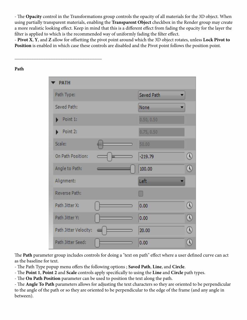
Path
The Path parameter group includes controls for doing a "text on path" effect where a user defined curve can act as the baseline for text.- The Path Type popup menu offers the following options ; Saved Path, Line, and Circle.- The Point 1, Point 2 and Scale controls apply specifically to using the Line and Circle path types.- The On Path Position parameter can be used to position the text along the path.- The Angle To Path parameters allows for adjusting the text characters so they are oriented to be perpendicular to the angle of the path or so they are oriented to be perpendicular to the edge of the frame (and any angle in between).

- The Alignment popup menu offers choices for the text to be Left, Right, or Center justified on the path - and also a choice to Distribute the text characters evenly so they are covering the entire path.- When enabled, the Reverse Path checkbox will cause the text to use the reverse side of the path for a baseline.
____________________________________
Letter TransformationsThe Letter Transformations parameter group includes controls for adjusting and animating various typographi-cal attributes of the text characters which are being extruded. For most of these parameters reading the param-eter label gives a good idea of its function.- The Tracking parameter offers a way to adjust and animate the tracking between the text characters.- The Leading parameter offers a way to adjust and animate the line leading between multiple lines text charac-ters.- The Baseline parameter can offset the baseline on which the text characters are arranged – particularly useful with text on a path.- The Letter Rotate parameter allows for rotating the letters (without rotating the text block as a whole).
____________________________________
Built-in LightThe Built-in Light parameter group includes controls for a single light source that can be controlled from within the filter.The total number of lights the 3D object will reflect is 3 so there are total of 3 Built-in Lights available that can be applied. Check boxes for number of Built-in-Lights to use are located towards the top of the effects window under Render:
The Built-in Light offers 3 Light Types to choose from ; Point, Spot, and Spot + Shadows.

- Point ; A Point light shines from the source in all directions and includes controls for X/Y and Z Position, Color, Intensity, and Attenuation. Attenuation lessens the intensity of the light rays as they extend from the source, allowing for the creation of a less directional distant diffuse light, similar to sunlight.- Spot ; A Spot light shines from the source toward a target (specified by Spot X/Y and Z parameters) and is limited to a cone defined by the Angle parameter and with edges softened by the Fall Off parameter.- Spot + Shadows ; A Spot + Shadows light is identical to a Spot Light, except that it is also capable of cast-ing shadows. The shadows it casts are limited to self-shadowing between 3D objects generated by the filter. The Width parameter can appear to soften the cast shadow edges. The cast shadows do not support partial trans-parency – meaning the shadows will appear as if the object being shadowed is fully opaque or fully transparent – and the Alpha Shadow Tolerance parameter defines the threshold for what the shadow considers opaque or transparent.____________________________________
Built-in CameraThe Built-in Camera parameter group includes parameters that affect the viewing perspective of the 3D object. When using the Built-in Camera, there are 3 options for what kind of Camera Model is used ; Position, Orbit, or Pan.
- Zoom ; all 3 Camera Models include a Zoom control for zooming the viewing perspective. By using a low Zoom value, and moving closer to the 3D object with the Position Z parameter (or Orbit Radius or Pan Dis-tance depending on the Camera Model), it’s possible to simulate a more wide angle lens perspective.
- Position Camera ; offers Position X, Y, and Z control for positioning the camera in 3D space, and offers 2 Camera Orientation options ; Free or Target. - When using Free Camera Orientation, the direction the camera is pointing is determined by the Tumble, Spin, and Rotate parameters. - When using Target Camera Orientation, the camera will always point in the direction of the target as determined by the Target X, Y, and Z parameters.
- Orbit Camera ; provides a convenient camera perspective for always facing the center (default Position of the 3D object) while allowing for simple orbit moves around the center using the Orbit Tumble, Orbit Spin, and Orbit Rotate parameters. Distance from the Center is determined by the Orbit Radius parameter.
- Pan Camera ; offers simple controls for panning horizontally using the Pan Advance parameter, and moving the camera in or out with the Pan Distance parameter.

________________________________
JitterThe Jitter parameter group includes controls for applying an auto-animated jitter to the text characters which are being extruded.
- The Jitter Seed parameter allows for varying the randomness of the jitter.- The Jitter Speed parameter controls how fast the auto-animated jitter is (frequency of the jitter)- The Jitter Position X and Y, Jitter Angle, and Jitter Scale X and Y parameters determine how much each of those attributes of the text characters is being jittered.- The Restrictions popup menu allows for limiting the jitter to one direction or the other (from default). For ex-ample when Jittering the Y Position, setting Restrictions to Negative Only will make it so all the jittering occurs above the baseline of the text (rather than allowing text characters to also dip below the baseline of the text).- The Polarize parameter pushes more of the text characters toward the extremes of the range in which they are jittering.- The Master Jitter Amount parameter scales all the individual jitter attributes together in a single parameter al-lowing for easier fading up and down of the overall Jitter effect .
____________________________________
Deformers
The Extruded Text filter includes several true 3D deformers for warping the 3D extrusion in various ways. The Deformers included in the filter are Bend-Taper-Twist, Curl, Shatter, Ripple, and Pulse.
________________ p
Bend-Taper-Twist Deformer
- Effect OrderAs the name suggests, Bend Taper Twist offers 3 distinct deformation processes and the Effect Order popup menu provides a way to determine the internal order in which the 3 deformations are applied to arrive at the final result.
- Bend Strength, Bend Radius, and Bend ModeBend Strength controls how much bend is applied and in which direction the bend goes, with positive values bending the left and right edges of the object forward and negative values bending them backward. Bend Radius defines the steepness of the bend curve. The Bend Mode popup menu provides 2 options for how the bend will appear. Using the Stretch mode, the Z scale of the object increases as the Bend radius increases, while using the Curve mode the Z scale does not change with the Bend Radius.
- Left Taper and Right TaperThe Left and Right Taper controls taper the Y and Z scale of each side of the object, with positive values giving a larger Y and Z scale and negative values giving a smaller Y and Z scale.
- Left Twist and Right TwistThe Left and Right Twist parameters twist each side of the object, with positive values twisting the object so the top part is bent forward while the bottom part is bent back – and negative values twisting the object so the top part is bent back while the bottom part is bent forward.
Center Offset X, Center Offset Y, and Center Offset ZCenter Offset X, Y, and Z provide a way to offset the deformations in 3D space.
___________________
Curl Deformer
- DirectionThe Direction popup menu determines what direction in 3D space the object will curl in using the Curl deform-er. The Guess choice tries to give a commonly desired result by curling along the longest axis in the direction of the shortest axis, and the Guess 2 choice curls along the longest axis in the direction of the second shortest axis. The other choices are labeled to allow for specifying what edges of the object are curled along which 3D axis.
- Reverse DirectionThe Reverse Direction check box reverses the direction of the curl in terms of which edge (Left, Right, Top, Bottom) begins the curl. For example a Left/Right curl begins on the right edge and moves left by default but it begins on the left edge and moves right with the Reverse Direction check box enabled.
- Curl 1 and Curl 2The Curl 1 and 2 parameters define a primary and a secondary curl when changed from their default values of zero, with positive values curling the edge of the object forward and negative values curling the edge back in 3D space.
- TightnessThe Tightness parameter tightens or loosens the Curl(s) by increasing or decreasing the size of cylindrical area(s) the object is rolled into as it is curling. A higher Tightness value rolls the object into a smaller cylinder while larger values roll it into a larger cylinder, with more or less of the object rolled farther into the cylinder depending on its size.
- MidpointThe Midpoint parameter will only seem to have an effect if Curl 2 is changed from its default to create a second-ary curl. In this case Midpoint determines the positioning of Curl 2 in relation to Curl 1
- AmountThe Amount parameter offers a way to control the overall progression if the curl effect in a single parameter. This allows for easy creation of animated curl effects where an object rolls or unrolls over time. The Amount parameter defaults to a value of 70 (rather than zero) so that the preceding parameters can be adjusted to design the curl while the effect is visible. For many commonly desired effects the Amount parameter will be animated over time in the final effect. For example in order to have an object begin as curled and to unroll to its un-curled state over time the Amount parameter is animated from some higher number back to zero. And in order to have an object begin un-curled and roll up over time the Amount parameter is animated from zero to some highernumber.
- Axis OffsetThe Axis Offset parameter allows for scaling the curl cylinder larger or smaller without rolling more or less of the object further into the cylinder – instead it will cause the curled part of the object to scale and distort to the new size.
- Bend 1 and Bend 2The Bend 1 and 2 controls provide a way to bend the object at the point of Curl 1 and Curl 2. The bend(s) are applied along the alternate access from the curl.
- ResolutionThe Resolution parameter controls how many curl points the deformer uses to internally calculate the curl. In most cases there is no reason to change this parameter from its default, but in some cases it is possible to make the curl appear smoother by increasing the Resolution value.
- Curl TypeThe Curl Type popup menu offers 2 choices ; 3D or Flat. The default choice of 3D will curl the object while maintaining its thickness while the Flat choice will flatten the object at the curl points.
- Noise ReductionThe Noise Reduction checkbox, which is enabled by default, prevents noise artifacts that can appear in certain types of curl effects. The speed of the curl effect can be increased by disabling Noise Reduction for effects where it does not seem to be necessary.
___________________
Shatter Deformer
- Polygon CountWhile it is not a parameter within the deformer itself (Polygon Count is a parameter in the Render group), the Shatter deformer shatters 3D objects based on the polygons / vertices that make up the geometry mesh of the shape, so the Polygon Count value (tesselation) of the object has a significant effect on the appearance of the shatter effect. Higher Polygon Count values result in more overall shatter pieces that are smaller, and lower Poly-gon Count values result in less overall pieces that are bigger. Lower Polygon Count values also result in faster performance. There are also ways to affect the size and number of the pieces fromwithin the Shatter deformer itself.
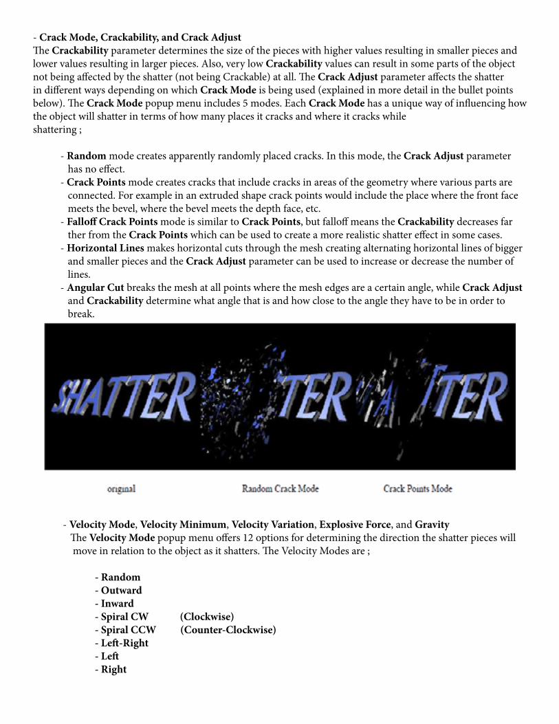
- Crack Mode, Crackability, and Crack AdjustThe Crackability parameter determines the size of the pieces with higher values resulting in smaller pieces and lower values resulting in larger pieces. Also, very low Crackability values can result in some parts of the object not being affected by the shatter (not being Crackable) at all. The Crack Adjust parameter affects the shatter in different ways depending on which Crack Mode is being used (explained in more detail in the bullet points below). The Crack Mode popup menu includes 5 modes. Each Crack Mode has a unique way of influencing how the object will shatter in terms of how many places it cracks and where it cracks whileshattering ;
- Random mode creates apparently randomly placed cracks. In this mode, the Crack Adjust parameter has no effect. - Crack Points mode creates cracks that include cracks in areas of the geometry where various parts are connected. For example in an extruded shape crack points would include the place where the front face meets the bevel, where the bevel meets the depth face, etc. - Falloff Crack Points mode is similar to Crack Points, but falloff means the Crackability decreases far ther from the Crack Points which can be used to create a more realistic shatter effect in some cases. - Horizontal Lines makes horizontal cuts through the mesh creating alternating horizontal lines of bigger and smaller pieces and the Crack Adjust parameter can be used to increase or decrease the number of lines. - Angular Cut breaks the mesh at all points where the mesh edges are a certain angle, while Crack Adjust and Crackability determine what angle that is and how close to the angle they have to be in order to break.
- Velocity Mode, Velocity Minimum, Velocity Variation, Explosive Force, and Gravity The Velocity Mode popup menu offers 12 options for determining the direction the shatter pieces will move in relation to the object as it shatters. The Velocity Modes are ;
- Random - Outward - Inward - Spiral CW (Clockwise) - Spiral CCW (Counter-Clockwise) - Left-Right - Left - Right
- Down - Back - Forward
- Velocity Minimum determines the minimum velocity for the slowest of the shatter pieces, while Velocity Variation determines how varied the velocity is between all the pieces, and also acts as a maximum velocity control. Explosive Force provides an easy way to alter the overall velocity curve so there is a burst of speed as the piece first shatters away from the main shape – the Explosive Force also gives a similar speed burst to the Spin Speed of the pieces which makes the explosive feeling of the shatter more convincing. Gravity exerts a pull on the shatter pieces (unless it is set to zero), and although it is outside of the slider range it is possible to scrub the numeric entry field or enter negative Gravity values to apply reverse gravity. To have no velocity to the shatter (so the object seems to crumble) set both Velocity Minimum and Velocity Variation to zero, and make sure there is some gravity value applied.
- Scatter Wipe Mode, Wipe Time, and Scatter OptionIt is possible to have the shatter effect progressively wipe from one part of the object to another rather than hav-ing the whole object shatter at once. This can be done by choosing one of the Scatter Wipe modes. The Scatter Wipe Mode popup menu offers 12 options for determining the direction the wipe will move in relation to the object. The Scatter Wipe Modes are ;
- None (no wipe, object will shatter all at once) - Left - Right - Right - Left - Top - Bottom - Bottom - Top - Back - Front - Front - Back - Random - Small – Large (small pieces first, followed by large) - Large – Small (large pieces first, followed by small) - Inside - Out - Outside - In
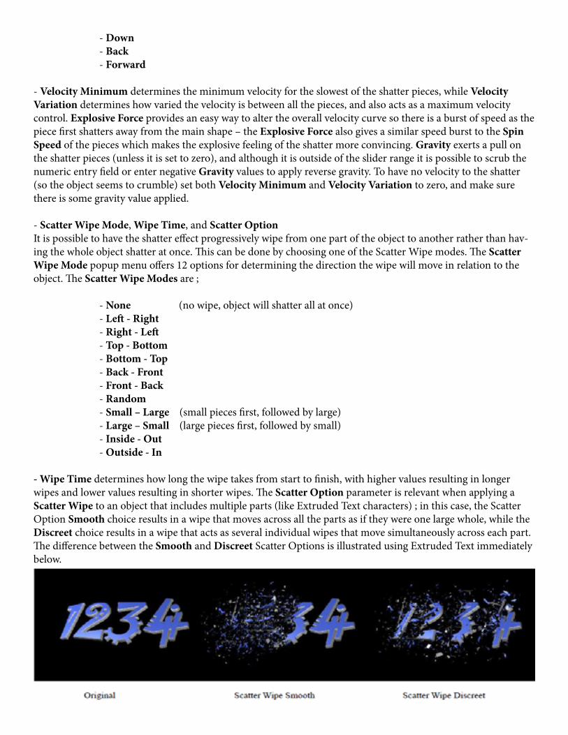
- Wipe Time determines how long the wipe takes from start to finish, with higher values resulting in longer wipes and lower values resulting in shorter wipes. The Scatter Option parameter is relevant when applying a Scatter Wipe to an object that includes multiple parts (like Extruded Text characters) ; in this case, the Scatter Option Smooth choice results in a wipe that moves across all the parts as if they were one large whole, while the Discreet choice results in a wipe that acts as several individual wipes that move simultaneously across each part. The difference between the Smooth and Discreet Scatter Options is illustrated using Extruded Text immediately below.

- DisplaceThe Displace parameter allows for pushing the shatter pieces out away from (or in toward) the center of the ob-ject. Positive Values push the pieces outward and negative values pull the pieces inward. This displacement is in addition to whatever shattering is going on based on other deformer parameters.
- Keep ThresholdThe Keep Threshold parameter allows for making it so some percentage of the shatter pieces stay in place rather than shattering away from the original object. Adjusting this parameter with various combinations of Crack Modes, Crackability, and Crack Adjust can give some interesting results.
- Spin Direction, Spin Speed, and Spin CharacterThe Spin Direction popup menu includes 7 options for determining which direction the shatter pieces will ro-tate as they shatter from the original object. The Spin Directions are ;
- Random All (all pieces randomly rotating) - Tumble Forward (all pieces tumbling on the X axis in one direction) - Tumble Both (some pieces tumbling on the X axis in one direction and some tumbling on the X axis in the opposite direction) - Spin Forward (all pieces spinning on the Y axis in one direction) - Spin Both (some pieces spinning on the Y axis in one direction and some spinning on the Y axis in the opposite direction) - Rotate Forward (all pieces rotating on the Z axis in one direction) - Rotate Both (some pieces rotating on the Z axis in one direction and some rotating on the Z axis in the opposite direction)
The Spin Speed parameter determines how fast and in which direction the shatter pieces rotate – positive values will cause a piece to rotate in one direction while negative values will result in that piece rotating in the opposite direction, and the rotation will be faster the further away from zero the value is. The Spin Character parameter defines a gradient that maps the difference in spin speed between the largest and smallest shatter pieces, allowing for having the larger pieces spin faster. Since Spin Character relates to Spin Speed, it is suggested to adjust these 2 parameters together in relation to each other.
- Time Scale, Time Mode, and Manual TimeBy default the shatter effect is set to auto-animate (with Time Mode set to Automated) so no interpolation keyframes are necessary for the object to shatter over time. When the shatter is Automated, Time Scale allows for slowing down or speeding up the overall speed of the shatter. As the parameter name indicates, Time Scale affects the whole time scale of the effect, so it will also affect the timing of a Scatter Wipe (if it is enabled) as well as the Spin Speed of the pieces, and even the effects of Gravity – so it is suggested that these other speed & time related parameters should be adjusted in conjunction with Time Scale. There are 4 Time Mode choices which are ;
- Automated (auto-animation that obeys Time Scale parameter) - Manual (animation progresses according to the Manual Time parameter and ignores Time Scale parameter) - Manual Move (the Velocity based movement and Scatter Wipe time progress according to the Manual Time parameter, but the Spin Speed behaves as Automated) - Manual Spin (the Spin Speed progresses according to the Manual Time parameter, but the Velocity based movement and Scatter Wipe time behave as Automated)

Since the Automated Time Mode always does a forward shatter (Time Scale does not accept negative values), using the Manual Time mode (animating from a higher to lower Manual Time value) is suggested for creating reverse shatter effects.
- Random SeedThe Random Seed parameter allows for tweaking the shatter to get a different result without changing any of the other significant parameters that create the look of the effect. This can be useful to help alter the shatter for a particular frame(s) while autoanimating, and it is also very useful for cases where there are multiple objects each using the same Shatter - since an identical appearance can be avoided by simply using different Random Seed values for each instance of the effect. This is a parameter that is left static in most common uses, since animating it will not result in a smoothly animating shatter.
___________________ p
Ripple DeformerThe Ripple deformer applies a ripple effect along the Z plane of the object.
- Center X/Y and StretchCenter X and Y determine the X/Y center point for the ripple effect. The ripple defaults to being a perfectly round circle ripple and the Stretch parameter allows for elongating the ripple shape in either direction resulting in an oval shape ripple. Combining certain Center X/Y and Stretch values also allows for the creation of effects that can appear more like a wave, including a horizontal or vertical wave.
- Phase and Time ScaleThe Ripple deformer auto-animates by default and the Phase parameter allows for offsetting the phase of the ripple autoanimation. The Time Scale parameter determines the speed of the ripple auto-animation with nega-tive values animating the ripples outward from the center and positive values animating in the reverse direction, with values farther away from zero being faster and values closer to zero being slower. It is also possible to manu-ally drive the ripple by setting the Time Scale to zero and animating the Phase parameter with keyframes.
- Amplitude and FrequencyAmplitude determines the height of the waves and Frequency determines the frequency of waves. Adjusting one of these parameters has some effect on the other so it is recommended to adjust them in relation to each other to get the desired result.

___________________
Pulse DeformerThe Pulse deformer offers several different deformations (in some cases similar to those found in other deform-ers) and offers a quick way to apply these deformations using repetitive auto-animation back and forth within a user determined range to allow for convenient creation of pulse like animations without requiring keyframing. The Pulse animation oscillates between the original undeformed object and the deformed object.
- Effect TypeThe Effect Type popup menu determines which kind of deformation will be applied to the object. There are 8 Ef-fect Type choices ; Bulge, Deform, and Lumpy are variations of a Bulge or sphereize type of effect. Bend, Twist, and Spin do exactly what the parameter names suggest with the Bend and Twist deformations being like those described previously in the Bend-Taper-Twist deformer, and the Spin choice applying a simple spin on the Y axis. Bounce moves the object up and down on the Y axis and Approach moves it back and forth on the Z axis.
- Pulse TypeThe Pulse Type popup menu determines the animation curve of the pulse cycle as the deformation animates from the original undeformed object to the most deformed state (determined by Amplitude parameter) and back again. There are 9 Pulse Type choices ;
- Breathing creates a pulse where the animation accelerates as it moves away from an extreme and decelerates as it gets closer to an extreme, with a slight pause between each back and forth. - Elastic pulse is similar to Breathing except with no pause between each back and forth animation. - Beat pulse decelerates as it moves away from the original undeformed object and uses linear interpo- lation (even speed) as it animates from the extreme back to the original – with no pause. - Bop pulse decelerates as it moves away from the original undeformed object and accelerates as it ani mates from the extreme back to the original – with a pause between pulses. - Uneven pulse is like elastic but the amplitude of the pulse varies so that some pulses are stronger than others. - Jerky pulse is like Elastic with a pause added midway between the undeformed and most deformed states, and the interpolation is such that it eases in and out of the extra pause. - Random pulse will cause the deformation to jump between various values. Using this Pulse Type the Amplitude parameter has no effect (the Random Pulse automatically uses amplitude values between zero and 100). The animation jumps between values using Hold style interpolation – meaning that it snaps between states rather than smoothly animating between them. - Snap pulse will snap back and forth between the original undeformed object and the most deformed state. The animation jumps between values using Hold style interpolation – meaning that it snaps between states rather than smoothly animating between them. - Paused pulse disables the pulsing auto-animation and the Frequency and Phase parameters have no effect using this Pulse Type. The other parameters such as Amplitude can still be used to adjust the static effect.
- Amplitude, Frequency, and Phase
The Amplitude parameter determines how much of the deformation is applied at the most deformed point in the pulse animation. Although it is outside of the slider range it is possible to scrub the numeric entry field or en-ter negative Amplitude values to reverse the direction of the deformation. The Frequency parameter determines the frequency of pulses, with higher values resulting in more frequent pulses and lower values resulting in less frequent pulses. The Phase parameter allows for offsetting the phase of the auto-animated pulse. It is also

possible to manually drive the pulse (and animate its frequency) by setting the Frequency parameter to zero and animating the Phase parameter with keyframes.
- Center Offset X and Y, Radius AdjustThe Center Offset X and Y parameters allow for offsetting the center of the deformation in X and Y space, while Radius Adjust determines the the size of the area in which the deformation is applied. When using the Spin Ef-fect Type, Radius Adjust has no effect.____________________________________