batteries need strong connections – are resistance, laser
TRANSCRIPT

BIULETYN INSTYTUTU SPAWALNICTWANo. 1/2019 53
Marcin Alexy, David van de Wall, Geoff Shannon, Mark L. Boyle
Batteries need strong connections – are resistance, laser and micro TIG welding the best suited joining technologies?
Abstract: The contacting of battery cells is very essential and technologically challenging step during the battery pack manufacturing. The goal is to achieve best weld joint without defects to enable high current flows. This requires high quality welding and joining process. A number of technologies is already well established respectively is typically used to solve most common applications. All three technologies resistance, laser and micro TIG welding are well suited for integration into production lines that may be either standalone or automat-ed operation. To maintain the required throughput that offers high quality and yields, it is important to have a clear understanding of which process is best for the particular battery pack size, tab and terminal material, type, and thickness. In addition, the selected process and integration solution should include process monitoring, process data management, and weld quality assessment.
Keywords: resistance welding, laser welding, micro TIG welding, battery welding
doi: 10.17729/ebis.2019.1/6
IntroductionThe world becomes more mobile and compo-nents become smaller and therefore the batter-ies and battery packs have become an integral part of everyday life. Batteries are used for port-able electronic devices, cordless power tools, en-ergy storage, hybrid and EV cars and in many other different application fields. The need for longer lasting batteries and battery packs, which continuously meet the increasing quality and production requirements is increasing. There are a number of materials joining requirements for battery manufacturing, depending on the specific type, size and capacity of the battery. Internal terminal connections, battery can and fill plug sealing, tab to terminal connections,
and external electrical connections are a few key examples.
Several joining options can be considered for each of these requirements, including re-sistance, ultrasonic, micro TIG and laser weld-ing. The decision to use one or the other is generally dictated by the specific type of weld required and production requirements. Ultra-sonic welding is commonly used for the join-ing of the internal electrode battery materials, which are usually constructed of thin foils of aluminum and copper. The remaining join-ing requirements – including the connections inside the can, and external terminal tab con-nections – are well suited to resistance, mi-cro TIG, and laser welding. For can and plug
Marcin Alexy, PhD, David Van de Wall – Amada Miyachi Europe; Geoff Shannon, PhD, Mark L. Boyle, PhD – Amada Miyachi America

No. 1/201954 BIULETYN INSTYTUTU SPAWALNICTWA
applications (seam sealing), laser welding is the joining technology of choice.
The following is an overview of resistance, micro TIG and laser welding technologies, along with examples of battery joining applications, detailing the key features of each technology.
Battery Packs BasicsToday’s battery packs come in a variety of con-figurations, as shown in Figure. 1.
Battery packs use several different battery types, including cylindrical, prismatic, ultra-capacitor, and pouch. Materials joining re-quirements vary depending on the battery’s specific type, size and capacity. Tab to terminal connections, internal terminal connections, tab welding, seam welding, fill port welding, short circuit protection, laser marking, and external electrical connections are a few key examples. Figure 2 shows the typical joining requirements for the different battery types. This article focuses primarily on welding tabs to terminals.
Welding tabs to terminals in battery pack manufacturingIn most cases, pack manufacturers receive in-dividual batteries from vendors, so the critical process step for pack manufacturing is joining the individual batteries together using a collec-tor plate, which consists of tabs for the individ-ual cells to be welded to both the positive and negative terminals. In addition, many packs will need a smaller number of collector plate to busbar connections. Along with considera-tions of materials, joint geometry, weld access, cycle time and budget, the welding technolo-gy selected will also be affected by the manu-facturing flow and production. Reviewing all these factors will usually point in the direction of the joining technology most suitable for the application: resistance welding, micro TIG and laser welding.
The traditional material for battery tabs is nickel because of its great welding properties. This can be easily welded to nickel, steel, stain-less steel, nickel plated steel and HILUMIN® bat-tery case materials. But nickel also has a relatively high cost, high weight, high electrical resistance and high stiffness. Copper is the most electrically conductive material for battery tab connections; only silver and gold are more conductive. Cop-per is relatively expensive. So, manufacturers may choose for aluminium in some applications. Copper’s electrical resistance is only two-thirds that of aluminium, which makes copper 1.5 times better from an electrical pack performance point of view. However, the price of copper battery tabs
Fig. 1. Typical battery pack configurations.
Fig. 2. Typical joining applications for the different battery types.

BIULETYN INSTYTUTU SPAWALNICTWANo. 1/2019 55
is about 15 times higher than that of aluminium and the weight is about four times higher. Manu-facturers should select copper for all applications where they are looking for maximum electrical efficiency or those that require the highest peak currents. Examples of tabs to terminals connec-tions manufactured by above mentioned three welding techniques are shown in Figure 3.
Battery pack welding technologies – advantages and disadvantagesThere are several different alternatives available for battery tab to connector welding, including laser welding, resistance welding, micro TIG (also known as micro-arc or pulse-arc welding) and ultrasonic welding. The right one depends upon the battery type, material and thickness of tabs, and the required production volume.
Resistance weldingResistance welding is the traditional welding technology used for battery pack manufacturing. This reliable technology has been around for years and requires relatively low invest-ment levels [1, 2]. Resistance weld-ing is a relatively straightforward process – the operator simply push-es down the battery tab with a weld head, which is operated by a cable or footswitch, and starts the weld. Recently also weld heads integrated into automatic or semi-automatic
welding system as shown in Figure 4. are be-coming more and more popular.
Because one is physically touching the part, resistance welding offers the easiest process data management and monitoring. The equip-ment can easily measure the welding process, including electrical parameters like current, voltage, resistance, power and mechanical pa-rameters like force, height and movement of electrodes during welding. One disadvantage of resistance welding is that the manufacturer is limited by the need to direct and concentrate the weld current using projections or dimples. The electrical connections are limited to one or two projections on each side of the battery, creating a total of two or four small area (typi-cally 0.5mm2) weld spots. Once these connec-tions are made, further welding current will
Fig. 3. Tabs to terminals connections manufactured by three most common welding techniques: left: resistance welding, middle: micro TIG, right: laser welding.
Fig. 4. Example of state of the art resistance welding weld head in-tegrated into automatic welding system: left: motorised MFP250-D
with spring follow-up system from Amada Miyachi, right: motorised MFP60-D from Amada Miyachi.

No. 1/201956 BIULETYN INSTYTUTU SPAWALNICTWA
flow over these connections, causing current shunting and preventing creation of any fur-ther connection area. The welding process of a battery tab can be carried out by two basic op-tions. In the first option the welding electrode is in direct contact with the tab to be welded and the contacting electrode is contacting the surface of the battery pole (see Figure 5 left). In the second option both welding electrodes are touching the tab and a slotted design of the tab needs to be used to enable defined welding cur-rent path through the tab and to increase the weld strength (see Figure 5 right)
A further disadvantage of resistance welding in today’s market stems from the fact that the process requires electrical resistance to create
the connection by melting material. As batteries become more efficient and powerful (with more energy current from a certain sized battery), there must be lower resistance in the connec-tions between batteries. In past battery applica-tions, the traditional materials used have been either nickel or HILUMIN®, an electro nickel-plat-ed diffusion annealed steel strip. Recently man-ufacturers have begun to use higher electrical conductor materials that feature lower electri-cal resistance, like copper or aluminium. Thicker materials are also being used to get a higher effi-ciency battery pack, since thicker material lowers resistance and makes it easier to pass current. As resistance draws closer to zero, resistance weld-ing becomes more and more difficult.
Fig. 5. Scheme of basic configurations to weld tab to a battery pole, left: one electrode is touching the tab; right: both electrodes are touching the slotted design battery tab
Fig. 6. Application examples of basic configurations to weld tab to a battery pole as described in Figure 5.
Fig. 7. Examples of battery packs welded with resistance welding technology. a) typical pack used in e-bikes, b) battery pack used in power tools, c) battery pack used in small size portable devices, d) battery with integrated connector.
a) b) c) d)

BIULETYN INSTYTUTU SPAWALNICTWANo. 1/2019 57
Experience shows that resistance welding is extremely well suited to welding nickel tab material up to approximately 0.4 millimeter thickness, and nickel or steel clad copper tab material to around 0.3 millimeter thickness thickness to a wide variety of terminal mate-rials [3].
Laser weldingAn important advantage of laser welding is its fast cycle time, so manufacturers will obtain more output than with resistance welding. In addition, laser welding is a non-contact pro-cess. No electrodes touch the part and there is very low pollution of the part. However, this can also be considered somewhat of a disad-vantage; because one is not physically touching the part, it is more difficult to achieve quality control compared to resistance welding. Laser welding is also not as strong as resistance weld-ing when it comes to process monitoring.
When welding battery tab connections, it is critical to ensure a zero air gap between the bat-tery and the tab. This zero air gap is inherent to the resistance welding process, but is not a fea-ture of laser welding. Therefore, laser welding equipment selected must take this into consid-eration. For example, Amada Miyachi recently developed a battery welding head that uses an integrated tab down holder to achieve the zero air gap as shown at Figure 8.
Laser welding: challenges of the state of the art battery packs
Over the last years the designers of battery packs for hybrid and electric automobiles, mo-torcycles, buses, heavy industrial vehicles, and hand-held power tools are looking for more energy to support the vehicle or device and increase its life. To do this, they must change the batteries’ electrode, isolator, and electrolyte, and lower its internal resistance to reduce en-ergy losses on a battery cell level. The lower the loss, the more efficiently energy is stored in the battery. These improved batteries store more
energy and can also charge and discharge fast-er, as measured by the battery’s “C” rate – the ratio between the charge/discharge acceptance and its capacity.
The higher voltages and currents generated by improved batteries means the battery in-terconnection (battery tab) must improve its electrical conductivity. The higher electrical conductivity results in lower electrical losses when charging and discharging, so more elec-trical energy is available for the vehicle or de-vice powered by the pack. By improving the electrical conductivity, the pack also stays cool-er during operation, which provides additional performance and battery lifetime benefits. Last, but not least, improving battery performance lowers costs, because fewer batteries are re-quired for a particular performance level. The three options for improving battery intercon-nect performance are:
Fig. 8. Example of a battery welding head with an inte-grated tab down holder to achieve the zero air gap. This battery laser welding head works up to 5kW CW, it has
integrated: tab down holder for zero airgap, XY stage for laser beam movement, shielding gas nozzle, fume ex-
traction nozzle, Z axis for tab down holder, camera for process, force and height measurement, it is designed and
manufactured by Amada Miyachi.

No. 1/201958 BIULETYN INSTYTUTU SPAWALNICTWA
a) using thicker tabs to carry more current, b) using different tab materials (for exam-
ple, copper or aluminum) with higher conductivity,
c) creating a larger tab to battery pole contact-ing area.
In the past, steel and nickel-based materials were commonly welded to the CRS (cold rolled steel) terminals. However, more recently, as bat-teries have move towards higher capacity and higher “C” values, designers began looking at using aluminum or copper materials for tabs to reduce electrical losses.
Laser welding: challenges of using traditional Nd:YAG lasers for welding dissimilar metals
This rise in the use of dissimilar material weld-ing comes with a variety of challenges for tra-ditional welding options like pulsed Nd:YAG (neodymium-doped yttrium aluminum gar-net) lasers, which typically make spots that are 0.5 mm in diameter with one pulse. Each weld pulse takes between 1 and 10 milliseconds; de-pending on its power level, the laser can gen-erate about 10 of these pulses every second [5]. To create a joint with sufficient electrical and mechanical properties, between 2 and 50 weld-ing spots must be placed on each battery pole (see Figure 9).
This method worked well for the traditional battery tab materials because of their weldabil-ity. However, welding of dissimilar materials is significantly more challenging because of:
– Different melting temperatures (see Table 1) – Different thermal expansion coefficients – Different absorption coefficient of laser light – Incompatible chemistry and atomic structures
Joining aluminum to stainless steel has always been an impossible welding combination.
The mixing of these two metals creates a brit-tle intermetallic zone leading to weld cracks.
Laser welding: innovative laser welding technologies
New laser technologies are rewriting the text-books on which materials can be joined to-gether. Single mode fiber lasers and lasers with nanosecond pulses are joining new combina-tions of metal that were previously not con-sidered compatible. The single mode laser can be focused to spot diameters of 20-50 microns. This makes a very small welding line of 20-50 microns wide, which can be pulsed like “a hot knife through butter” to make a weld. The linear speed of this laser beam movement is typical-ly in the 100 to 1000 mm/sec (4-inch-40-inch/ second) range [6] (See Figure 10).
To create sufficient joint area, the length of this joint needs to be 10 to 100 mm per bat-tery pole. To fit this onto the 3 to 6 mm diam-eter available on a battery pole, the line must
Fig. 9. Traditional laser weld of battery tab showing several large (200-600 micron) weld spots. Weld spots or seam can be tailored to both strength and conductivity, left: approx. 60N peel strength, middle: approx. 250N peel strength,
approx. 180N peel strength in all directions.
Table 1. Melting points of alloysCombination Melting Temperature, °C
Aluminum/Steel 660/1500Aluminum/Cooper 660/1080
Aluminum/Titanium 660/1700

BIULETYN INSTYTUTU SPAWALNICTWANo. 1/2019 59
Fig. 10. Copper battery tab welded to steel battery can with single mode laser
Fig. 11. Aluminum battery tab welded to a nickel plated cold rolled steel can using the spiral weld technique (R1: Inner Radius = 0.02mm, R2: Outer Radi-
us = 0.5mm, a: Ramp = 3mm; b: Rise = 0.02mm)
Fig. 12. Application photo of aluminum battery tab welded to a nickel plated cold rolled steel can using the spiral weld technique
be in a spiral shape or concen-tric circles, rather than spots. Us-ing a galvo scanning weld head, the total weld can be very fast; it takes about 50 milliseconds of weld time.
Another method of welding dissimilar metals is to concen-trate the laser energy in time by using nanosecond pulsed fib-er welding instead of the tra-ditional millisecond pulse. The weld pulses are typically 100,000 times shorter, providing energy in a much shorter period. This increases the laser peak pow-er level by the same amount. The spot size is also very small, about 30 to 40 microns. The high peak power on a small area re-sults in such a high peak pow-er density that all metals are molten. This process can be best described as “pushing a hot nee-dle in the material and pulling it out again.” The spots are very small, so a great many spots are needed, typically 10,000 or more. As the timeframe for cre-ating one spot is very small, the laser can be fired at high repeti-tion rates, typically 30 kilohertz (kHz) and above.
The best method of getting enough weld spots with the nanosecond laser on a small area like a battery pole is to make a line coiled into a spiral. This spiral is typically welded from the inside to the outside, so the laser beam always
“sees” a fresh and cold piece of metal in front of it. If the laser went from the outside to the inside, there would be heat build-up and in-creased penetration depth towards the center, as the part heats up during the welding. Figure 11 shows an example of a spiral weld made on aluminum tab material.
Testing showed single layers shear strengths of around 44 N (10 pounds) and double layer shear strength at around 88 N (20 lbs.). Figure 12 is an application photo showing an alumin-ium battery tab welded to a nickel-plated cold rolled steel can using the spiral weld technique.
A closer look at the cross sections reveals that the spot welds do not show the character-istic form of conventional pulsed spot welds – they more closely resemble multi-staking. The intermetallic zone was less than 10 microns. Pull strength was good and peel strength was

No. 1/201960 BIULETYN INSTYTUTU SPAWALNICTWA
adequate. There was barbed solidification of aluminum into steel.
One example of the new technology is 70-Watt LMF70-HP OEM fiber laser, which can be integrated into the LMWS pulsed fiber laser welding system from Amada Miyachi. Such a unit is an advanced processing system for welding battery cans with wall thicknesses of 300-350 microns. It features shorter pulses, re-sulting in less mixing of materials, and hence less of an intermetallic zone and less brittleness with aluminum tab materials. This laser solu-tion is good for contract manufacturing set-tings, where operators may be producing one product one day and something different the next. The XY galvo program quickly positions welds; a new program can be loaded in as little as five minutes, and operators can be ready to start the next product.
Laser welding: summary conclusion laser
New laser sources, including single mode fiber lasers and lasers with nanosecond pulses, pro-vide an important opportunity for dissimilar metal joining by enabling the joining of alumi-num and copper battery tab material, which re-duce electrical resistance and improve battery performance. Tests have shown the technolo-gy works well with metal thickness of less than 0.25 millimeters (mm), providing good pull and peel strengths in these dissimilar joints. With that this new technology shows great promise for a wide range of industries.
Micro-arc Tungsten Inert Gas (TIG) welding (micro TIG welding)Micro TIG welding is a highly efficient non-con-tact method for generating localised heat and is frequently used for welding conductive bat-tery interconnects. Precision micro TIG weld-ing requires a controlled current to be passed into an electric arc. The heating effect is direct-ly proportional to the current and resistance of the arc, which itself depends upon the arc gap. With a fixed gap, the arc resistance develops
a voltage across it by virtue of the welding cur-rent, this can then be used as a process moni-toring variable [7].
A wide range of closed-loop controlled cur-rent micro TIG welding units which are suita-ble for conductive material welding to battery packs are available on the market. In combina-tion with custom TIG torches that provide elec-trical return contacts and arc shielding, these units are readily configured for manual battery pack assembly or high volume, multi-spot bat-tery pack assembly with automatic step and re-peat torch positioning.
As stated already, similarly to resistance welding, a controlled and therefore easily mon-itored current is passed into the elements to be
Fig. 13. The generic schematic of a micro TIG welding machine
Fig. 14. Example of state of the art micro TIG welding components: left: PAxxP Pulsed Arc Power Supplies, right:
TR-16A Touch Retract Torch from MacGregor Welding Systems.

BIULETYN INSTYTUTU SPAWALNICTWANo. 1/2019 61
welded. Compared with resistance spot welding, localised heating into the battery itself is gener-ally lower. Unlike resistance welding, the heat generated is due to the resistance of the elec-tric arc and its associated current, and hence is independent of the product conductivity. This therefore provides a highly controlled meth-od of developing localised welding tempera-tures that are suitable for joining materials up to 0.5 mm in thickness onto conductive bat-tery cans.
For example, the TIG battery welding pro-cess has been tested and proven with a num-ber of high integrity lithium ion designs with excellent electrical and mechanical results, us-ing nickel, aluminium and copper flat sheets to a maximum thickness of around 0.5 mm. The high degree of control offered by the pow-er source enables the resultant spot welds to be optimised to size while minimising battery can heat penetration. In addition with micro TIG welding, manufacturers can make use of mul-tiple heads from one unit and they are also able to weld plated materials.
The major disadvantage of the micro TIG pro-cess for welding battery packs is the large heat affected zone. The tungsten electrode wears over time and requires cleaning and sharpening.
Ultrasonic weldingUltrasonic welding was originally used in bat-tery pack applications because of its ability to
weld dissimilar metals, for example, welding al-uminium to copper. As laser welding has de-veloped this capability, it has largely supplanted ultrasonic welding for welding dissimilar met-als. The main disadvantage of ultrasonic weld-ing is the potential for the vibration to damage parts. In addition, ultrasonic welding requires use of a sonotrode – a tool that creates the ul-trasonic vibrations. The sonotrode is a stack of piezoelectric transducers attached to a tapering metal rod. The tool gradually wears out, so the process will shift over time. Ultrasonic welding is also very sensitive to any pollution between the two materials. Pollution as insignificant as the grease of a fingerprint can completely throw off the process. Ultrasonic welding also creates more heat than other processes, which can damage batteries. The mechanical strength is less and electrical resistance is higher
Understanding which technology to select for battery pack manufacturingBattery pack production volumes are driven by the demands of consumer electronics and electric vehicles. Likewise, the manufacturing and joining needs are determined by the pack size, type and thickness of the busbar, and tab and terminal materials. All described in this article joining technologies, i.e. resistance, mi-cro TIG, laser and ultrasonic welding technolo-gies each have specific features that align well to these joining needs. A clear understanding
Fig. 15. Battery welding by micro TIG, left: examples of TIG welded battery tabs, right: TIG torch and battery spot weld

No. 1/201962 BIULETYN INSTYTUTU SPAWALNICTWA
of the technologies and application is needed to implement an efficient and reliable produc-tion battery pack welding system.
Automating the welding process of battery pack tabsEnsuring quality is an important driver for all battery pack manufacturers. The human factor causes the largest variation in quality. Differ-ent operators working over several days using the same equipment will create wide variation. That is why it is critical for manufacturers to select equipment that provides the highest lev-el of quality control, while producing a stable and reproducible process. Minimising or re-ducing labour costs is a consideration, but au-tomating the battery pack tab welding process is not done only to lower labour costs. By se-lecting equipment that puts all the movements into the system, operator variation is removed and quality improved.
Among others Amada Miyachi designs and manufacture a complete range of resistance welding and micro TIG as well as laser auto-mated or semi-automated systems specifically designed for both low and high-volume man-ufacturing processes.
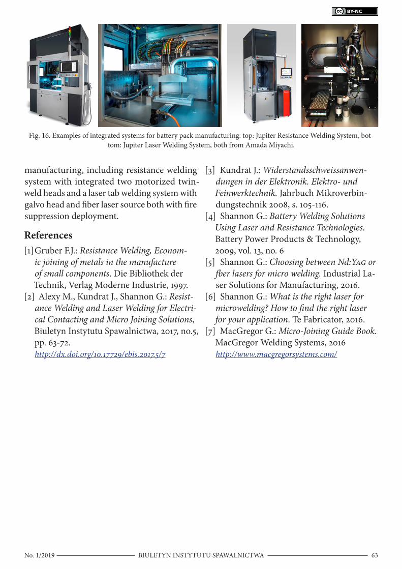
Application experts recommend the right system based and application-specific param-eters. These systems are suited for integration into bigger multi-processes production lines. They are being used for welding battery mod-ules by a variety of manufacturers, including high-performance lithium battery module manufacturers located in many countries, like the Netherlands, Germany, UK, Ireland, Isra-el and several further countries of mostly in central Europe. Such efficient, automated sys-tems twill help move the industry forward by accommodating their growing produc-tion requirements. Figure 16 shows some ex-amples of integrated systems for battery pack
Table 2. Comparison of the most widely used battery pack welding technologies.
Welding technology Advantages Disadvantages Material
thicknessSpeed (welds per second) Consumables
Resistance
Closed loop feedback and monitorable process
Self-toolingAble to weld plated
materials
Limited connection areaCannot be used with
higher electrical conductor material
0.2 to 5mm Up to 1 Electrode
Laser
High speedSmall heat affected zoneTailored weld patterns
Various joint geometriesWeld dissimilar metals
Able to weld plated materials
More difficult to achieve quality control
More difficult to achieve process
monitoring
0.2 to 2mm Up to 20
Cover gasCover glass
Micro TIG
Multiple heads from one unit
Able to weld plated materials
Large heat affected zoneElectrode wears
0.2 to 2mm Up to 1
Electrode Cover gas
Ultrasonic Weld dissimilar metals
Self-tooling
Vibration damageHigher heat can damage
batteriesExpensive consumables
0.2 to 2mm Up to 1 Sonotrode
BIULETYN INSTYTUTU SPAWALNICTWANo. 1/2019 63
manufacturing, including resistance welding system with integrated two motorized twin-weld heads and a laser tab welding system with galvo head and fiber laser source both with fire suppression deployment.
References[1] Gruber F.J.: Resistance Welding, Econom-
ic joining of metals in the manufacture of small components. Die Bibliothek der Technik, Verlag Moderne Industrie, 1997.
[2] Alexy M., Kundrat J., Shannon G.: Resist-ance Welding and Laser Welding for Electri-cal Contacting and Micro Joining Solutions, Biuletyn Instytutu Spawalnictwa, 2017, no.5, pp. 63-72.http://dx.doi.org/10.17729/ebis.2017.5/7
[3] Kundrat J.: Widerstandsschweissanwen-dungen in der Elektronik. Elektro- und Feinwerktechnik. Jahrbuch Mikroverbin-dungstechnik 2008, s. 105-116.
[4] Shannon G.: Battery Welding Solutions Using Laser and Resistance Technologies. Battery Power Products & Technology, 2009, vol. 13, no. 6
[5] Shannon G.: Choosing between Nd:YAG or fber lasers for micro welding. Industrial La-ser Solutions for Manufacturing, 2016.
[6] Shannon G.: What is the right laser for microwelding? How to find the right laser for your application. Te Fabricator, 2016.
[7] MacGregor G.: Micro-Joining Guide Book. MacGregor Welding Systems, 2016http://www.macgregorsystems.com/
Fig. 16. Examples of integrated systems for battery pack manufacturing. top: Jupiter Resistance Welding System, bot-tom: Jupiter Laser Welding System, both from Amada Miyachi.