bathroom installation guide
TRANSCRIPT

Bathroom Installation Guide
Please read instructions carefully and check products beforestarting.
Products should be fitted/installed by an experienced andcompetent fitter, failure to do so may invalidate your
guarantee.
Fitting instructions refer to fitting furniture to a solid wall,please use appropriate fixings for the wall type.
For any defective materials please contact your supplier
Please note: Under our policy of continual improvementwe reserve the right to alter materials and or specificationin-line with our product and service development
175DIS-VER 1.5/16-12-15
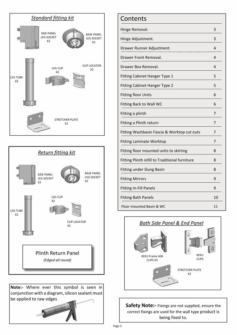
Note:- Where ever this symbol is seen inconjunction with a diagram, silicon sealant mustbe applied to raw edges
Standard fitting kit
SIDE PANELLEG SOCKET
X2
BASE PANELLEG SOCKET
X2
LEG TUBEX2
LEG CLIPX2
CLIP LOCATORX2
STRETCHER PLATEX2
Return fitting kit
SIDE PANELLEG SOCKETX2
BASE PANELLEG SOCKETX2
LEG CLIPX2
CLIP LOCATORX2
Plinth Return Panel(Edged all round)
Page 2
Safety Note:- Fixings are not supplied, ensure thecorrect fixings are used for the wall type product is
being fixed to.
LEG TUBEX2
ContentsHinge Removal. 3
Hinge Adjustment. 3
Drawer Runner Adjustment. 4
Drawer Front Removal. 4
Drawer Box Removal. 4
Fitting Cabinet Hanger Type 1 5
Fitting Cabinet Hanger Type 2 5
Fitting floor Units 6
Fitting Back to Wall WC 6
Fitting a plinth 7
Fitting a Plinth return 7
Fitting Washbasin Fascia & Worktop cut outs 7
Fitting Laminate Worktop 7
Fitting floor mounted units to skirting 8
Fitting Plinth infill to Traditional furniture 8
Fitting under Slung Basin 8
Fitting Mirrors 9
Fitting In-Fill Panels 9
Fitting Bath Panels 10
Floor mounted Basin & WC 11
KEKUCLIPS
Bath Side Panel & End Panel
STRETCHER PLATEX2
KEKU Frame ASRCLIPS X3

B A
C
D T� ������ ����● Start with the bottom hinge first while supporting the door,
release the hinge body by depressing the catch at the rear ofthe hinge body (D) which is hidden under the arm.
● Slide the hinge arm off and forward releasing hinge from theback plate.
● Re-fit hinge by sliding hinge onto back plate and pressing downat the rear of the hinge arm until and audible click is heard.
● To remove hinge from door turn screw (E) ¼ of a turnanticlockwise, when re-fitting do not over tighten with impactdriver
E
H���� R������
To adjust door verticallyOverlay adjustment
Clockwise
Anti -Clockwise
To adjust door in & out
CarcaseDoor
ClockwiseAnti-Clockwise
Turn screw BTurn screw ASlacken screw C on back-plate
To adjust door vertically
H���� A����������
Page 3
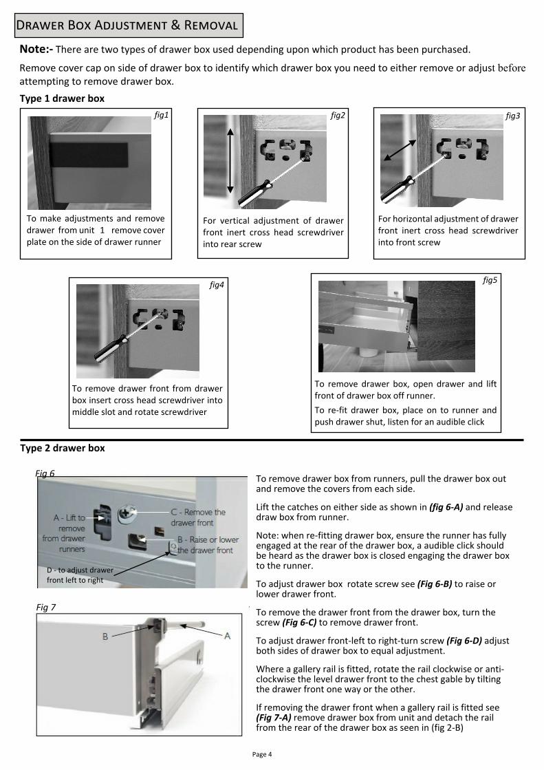
To remove drawer front from drawerbox insert cross head screwdriver intomiddle slot and rotate screwdriver
fig4
To remove drawer box, open drawer and liftfront of drawer box off runner.To re-fit drawer box, place on to runner andpush drawer shut, listen for an audible click
fig5
To make adjustments and removedrawer from unit 1 remove coverplate on the side of drawer runner
fig1
For horizontal adjustment of drawerfront inert cross head screwdriverinto front screw
fig3
For vertical adjustment of drawerfront inert cross head screwdriverinto rear screw
fig2
D����� B�� A��������� & R������
Note:- There are two types of drawer box used depending upon which product has been purchased.
Remove cover cap on side of drawer box to identify which drawer box you need to either remove or adjust beforeattempting to remove drawer box.
Page 4
To remove drawer box from runners, pull the drawer box outand remove the covers from each side.
Lift the catches on either side as shown in (fig 6-A) and releasedraw box from runner.
Note: when re-fitting drawer box, ensure the runner has fullyengaged at the rear of the drawer box, a audible click shouldbe heard as the drawer box is closed engaging the drawer boxto the runner.
To adjust drawer box rotate screw see (Fig 6-B) to raise orlower drawer front.
To remove the drawer front from the drawer box, turn thescrew (Fig 6-C) to remove drawer front.
To adjust drawer front-left to right-turn screw (Fig 6-D) adjustboth sides of drawer box to equal adjustment.
Where a gallery rail is fitted, rotate the rail clockwise or anti-clockwise the level drawer front to the chest gable by tiltingthe drawer front one way or the other.
If removing the drawer front when a gallery rail is fitted see(Fig 7-A) remove drawer box from unit and detach the railfrom the rear of the drawer box as seen in (fig 2-B)
Fig 6
Fig 7
Type 1 drawer box
Type 2 drawer box
D - to adjust drawerfront left to right
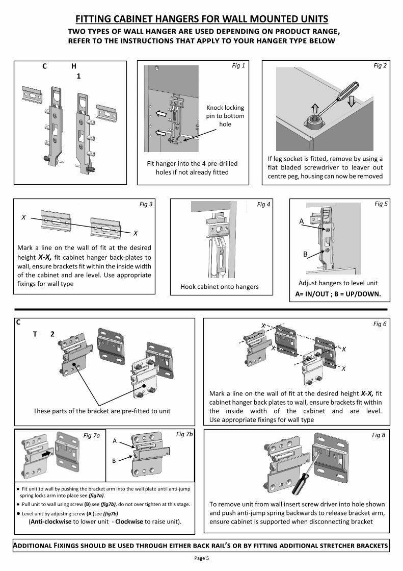
FITTING CABINET HANGERS FOR WALL MOUNTED UNITS��� ����� �� ���� ������ ��� ���� ��������� �� ������� �����,����� �� ��� ������������ ���� ����� �� ���� ������ ���� �����
X
X
Fig 3
Mark a line on the wall of fit at the desiredheight X-X, fit cabinet hanger back-plates towall, ensure brackets fit within the inside widthof the cabinet and are level. Use appropriatefixings for wall type
Fig 4
Hook cabinet onto hangers
A
B
Fig 5
Adjust hangers to level unitA= IN/OUT ; B = UP/DOWN.
Knock lockingpin to bottom
hole
Fig 1
Fit hanger into the 4 pre-drilledholes if not already fitted
Fig 2
If leg socket is fitted, remove by using aflat bladed screwdriver to leaver outcentre peg, housing can now be removed
C H 1
These parts of the bracket are pre-fitted to unit
C T 2
X
X
XX
Mark a line on the wall of fit at the desired height X-X, fitcabinet hanger back plates to wall, ensure brackets fit withinthe inside width of the cabinet and are level.Use appropriate fixings for wall type
Fig 6
To remove unit from wall insert screw driver into hole shownand push anti-jump spring backwards to release bracket arm,ensure cabinet is supported when disconnecting bracket
Fig 8
A��������� F������ ������ �� ���� ������� ������ ���� ����’� �� �� ������� ���������� ��������� ��������Page 5
B
AFig 7b
● Fit unit to wall by pushing the bracket arm into the wall plate until anti-jumpspring locks arm into place see (fig7a).
● Pull unit to wall using screw (B) see (fig7b), do not over tighten at this stage.
● Level unit by adjusting screw (A )see (fig7b)(Anti-clockwise to lower unit - Clockwise to raise unit).
Fig 7a

Page 6
Fig 1
Remove doors, shelf, drawers and fasciaand turn unit upside down to fit legs.
Fig 2
Take leg tubes from the Standard Fitting kit andfit to pre-fitted leg socket, ensure leg tube ispushed firmly home. Before adjusting leg heightto 175mm.
F���� M������ U����
B��� T� W��� WC ����
To fit worktop.● Fix stretcher brackets to gables
and fix work-top into place.● If unit has a front rail drill hole
through rail and fix work-topthrough rail.
Fig 3
● If a plinth return is required, fit a third legfrom the Return Fitting kit.
● Fit the leg socket to the pre-drilled hole inthe base
● Push peg in leg socket down to secure andfix.
● Finally fix socket with No6 x ¾ screws intobase.
When joining unitsplace fixings
discreetly
Fix unit to wall through rear railor brackets use correct fixings
for wall type
● Stand unit back on to its legs and position against wall.● If fitting another floor unit in a run place against the first
unit and fix together through adjacent gables.● Its recommend that fixing are placed discreetly behind
hinges or behind shelves.● Level units and fix through rear rails or stretcher brackets
Mark front fascia and plinth to take panconnector & flush pipe, as required.
Fig 7
Front panel & plinth.
● Cut for pan connector and the flush pipe.● Ensure cut surfaces are sealed with a silicon sealer
when refitting.
Fig 8
Position unit into place and level unit in alldirections by adjusting feet.
● Fix unit into position before fitting cistern.● Drill fixing holes through rear top rail, & fix into
place, additional stretcher brackets and fixingscan be used as required.
● Use appropriate fixings for wall type
Fig 6Fix unit to wall through toprail or stretcher plates
Fig 4
● Remove front fascia, turn unit upside down (Fig 4)● Fix leg socket into place with 4 off - 5 x ¾ screws● Take leg tube from the Standard Fitting kit and fit into leg
socket by pushing the leg tube firmly into the leg socket● Ensure its fully inserted & adjust leg to 175mm.
To fit legs If a plinth return is added, fit the third leg socketfrom the Return Fitting kit.● Fit housing into the pre-drilled holes in the gables● Fix leg socket into place with 4 off - 5 x ¾ screws.● Insert leg tube into socket as (fig 4) and adjust to
175mm in line with the front legs.
Fig 5
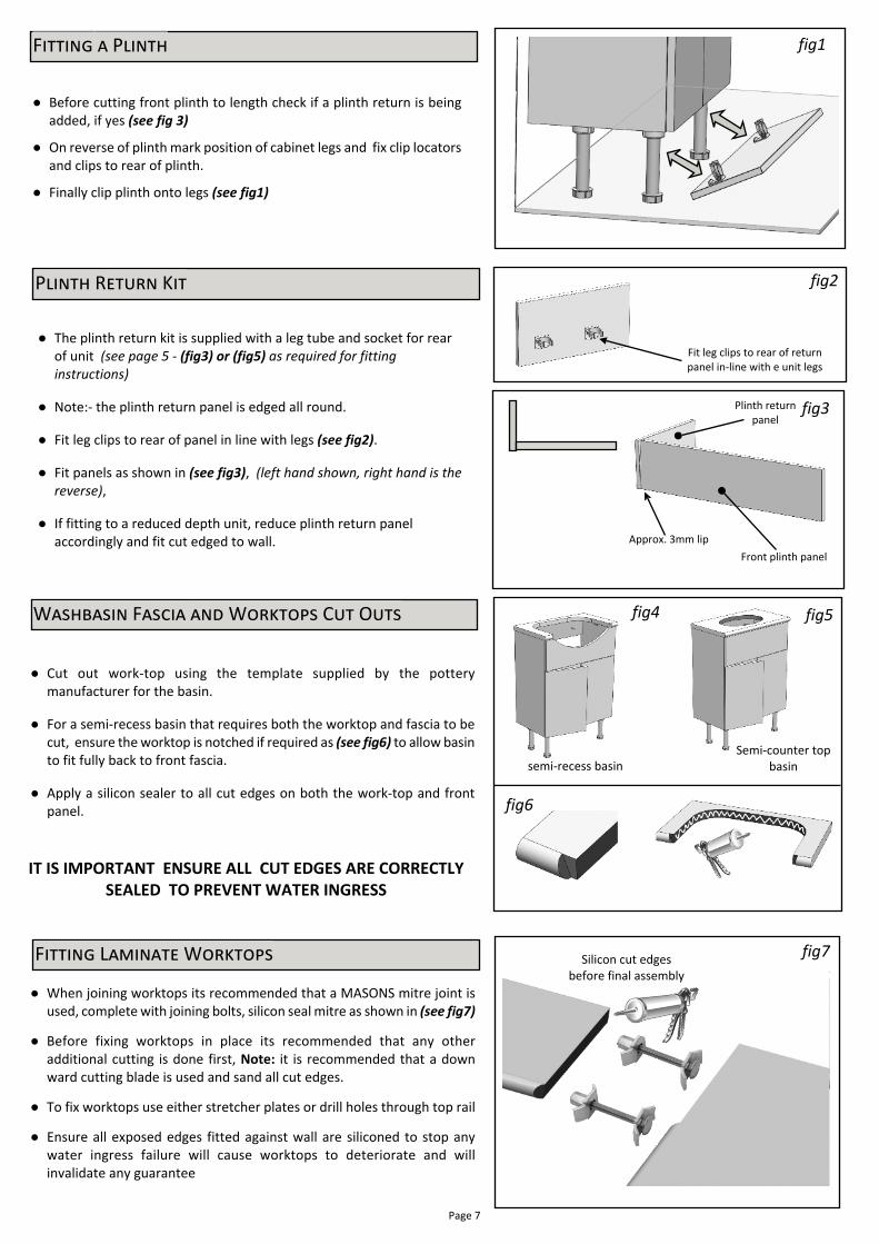
● When joining worktops its recommended that a MASONS mitre joint isused, complete with joining bolts, silicon seal mitre as shown in (see fig7)
● Before fixing worktops in place its recommended that any otheradditional cutting is done first, Note: it is recommended that a downward cutting blade is used and sand all cut edges.
● To fix worktops use either stretcher plates or drill holes through top rail
● Ensure all exposed edges fitted against wall are siliconed to stop anywater ingress failure will cause worktops to deteriorate and willinvalidate any guarantee
P����� R����� K��
● Before cutting front plinth to length check if a plinth return is beingadded, if yes (see fig 3)
● On reverse of plinth mark position of cabinet legs and fix clip locatorsand clips to rear of plinth.
● Finally clip plinth onto legs (see fig1)
F������ � P����� fig1
fig6
● Cut out work-top using the template supplied by the potterymanufacturer for the basin.
● For a semi-recess basin that requires both the worktop and fascia to becut, ensure the worktop is notched if required as (see fig6) to allow basinto fit fully back to front fascia.
● Apply a silicon sealer to all cut edges on both the work-top and frontpanel.
IT IS IMPORTANT ENSURE ALL CUT EDGES ARE CORRECTLYSEALED TO PREVENT WATER INGRESS
W�������� F����� ��� W������� C�� O��� fig4 fig5
Semi-counter topbasinsemi-recess basin
● The plinth return kit is supplied with a leg tube and socket for rearof unit (see page 5 - (fig3) or (fig5) as required for fittinginstructions)
● Note:- the plinth return panel is edged all round.
● Fit leg clips to rear of panel in line with legs (see fig2).
● Fit panels as shown in (see fig3), (left hand shown, right hand is thereverse),
● If fitting to a reduced depth unit, reduce plinth return panelaccordingly and fit cut edged to wall.
Page 7
F������ L������� W������� Silicon cut edgesbefore final assembly
fig7
Front plinth panelApprox. 3mm lip
Fit leg clips to rear of returnpanel in-line with e unit legs
Plinth returnpanel
fig3
fig2

● Where its required that floor mounted furniture is fitted back tothe wall, either scribe end panels around skirting or alternativelyfit skirting up to side panels of unit (see fig1)
S������� P�����
With plinth in-fill panel
● With the traditional style floor mounted furniture there is the option tofit a infill panel as supplied, this can be fixed into place either by fixingwith double side tape (not supplied) or fix in place with screws, howeverensure length of screw does not come through of plinth (see fig 2 & 3)
Without plinth in-fill panel
● Under slung basins are support by a cradle, pre-fitted to base unit on 4stretcher brackets which will require final adjustment as below (see fig4)
Fig 1
10mm
Level basin andadjust height
Fig 5b
● Slacken screws off in the stretcher bracket (see fig5a) andadjust height of basin, so that the basin sits 10mm taller thanthe side gables, (see fig5b) ensure basin is also level.
● This will allow the worktop to sit on gables and the basin to fitflush to the underside of the worktop
Slacking screw and adjust height of cradleas below.
Once cradle is correctly adjusted, re-tighten screw add a 2ⁿ screw into thehorizontal slot
Fig 5a
● We suggest that the tap assembly is pre-fitted to worktop beforefitting,
● Once basin and cradle are correctly adjusted, apply a bead ofsilicone along the top edges of the gables and around the lip ofbowel, fit worktop to unit and bowel, wipe clean and remove anyexcess of silicon, allow sufficient time for the sealer to harden. seefig 6
Fig 3
Fig 2
Fig 4
Basin cradle
Fig 6
Page 8
T���������� ����� ��������� - O������������� ��-���� �����
F������ ����� ����� �����

F������ � R�������� M�����
Fit mirror inserts into rear of mirror, (see fig1)
Note:- Mirror can be fitted either portrait or landscape directions,ensure inserts are aligned in the correct direction (see fig2) for theorientation required.
(Note:- Once the plastic inserts have been fitted they cannot beremoved)
Mark wall of fit to suit the correct spacing between inserts and that thefixing locations are level, ensure that the appropriate fittings are usedfor the wall type.
Hang mirror onto wall.
Ensure inert's are fitted for the correctorientation required
fig1
Page 9
fig2
C������� ������ ���� ������ ���������
Cladding panels with infill to a wall. (See fig 3)External Filler
fig3
fig5
Slide into
place
CladdingPanel
Trim Cladding panel tofinish level with startof edge profile where
required
fig4R������������� ������ ������� �������� ����� (��� ��� 4)
Before fitting cladding panels its recommended that where there is a largebevel or radius to the edge of the door or fascia, that the panel is reducedin depth so that the edge of the cladding panel is level with the start ofthe bevel, or panel can be left flush with front fascias or door fronts.
If cladding panel is cut, fit cut edge against the wall and seal as appropriate
E������� ������ �� �������� �����Measure and mark or scribe the filler panel, cut panel as required , fix thefiller panel to the cladding panel with either stretcher brackets or awooden baton (see fig 5).
Slide both parts into position (see fig 5) and secure by screwing throughbase unit gable, ensure fixings are placed in a discrete position inside gable.

Note: To fit bath panels timber under the bath rim is required to hold the bath panel clips. In the event that thebath does not have timber for the clips, the installer will need to fit timber to the under side of the bath rim as
necessary, depending on tiling the bath panels may require trimming.
All cut panels must be sealed with silicone sealer
F������ ���� ������
When the bath has an end panel, fix with stretcher platesto the timber under the bath rim and to the wall(see fig 1) (Use appropriate fixings for wall type ) .
Two Keku clips can be fitted to the front edge of the endpanel to allow the bath side panel to be clipped into place
Three Keku clips can be fitted to the timber under the bath rimso that the side panel can be clipped into position (see fig 2)
The two stretcher plates can be fixed to wall(Use appropriate fixings for wall) type) approx. 300mm fromthe underside of the bath as stops for the bath panel (see fig 3)
S��� P����
E�� P����
Fit stretcher Plate approx. 300mm fromunderside to support bath end panel
(Use appropriate fixings for wall type)
Bath End Panel
Wall
Stretcher bracketfitted to timber
Keku clips
Fig1.
Keku clips
Fig2.
Stretcher plate fixed to wall to support sidepanel when clipped into position
(Use appropriate fixings for wall) type)
Fig3.
Page 10

Units can be fitted either as separate units (Fig 1 & 2) or in arun (Fig 3) with the WC fitted to either side of the wash basinunit
When the WC unit is fitted on its own ensure you centralisethe work top so that hangs equally over each side of the unit(Fig 2)
When the units are fitted in a run ensure the work top fitsunder the basin
To fit the cistern into the WC unit pull the front topfascia off the unit
To remove the front panel lift upwards once the fronttop panel has been removed.
Fix work top down using two stretcher brackets
To fix unit to a wall drill through rear top rail as required,additional stretcher brackets can be used if required
Fig1. Fig2.
Fig3.
Front Top Panel
Front Panel
When fitting the wash basin to the unit ensurebasin sits on bed of silicon sealant (Fig 4)
Once basin is fitted ensure silicon sealant isapplied to all edges
Floor mounted Basin & WC