batch controlling - s3-us-west-2.amazonaws.com
TRANSCRIPT

DESIGN GUIDEBATCH CONTROLLING
SY
ST
EM
DE
SIG
N S
YS
TE
M L
AY
OU
TC
OM
PO
NE
NT
SE
LE
CT
ION

2 \ Batch Controller Design Guide

Piping System Design
Single Stage (single valve) System
System Components
Piping Layout
Designing a Pneumatic Control System
Electrical System Layout
Glossary
Introduction
Benefits of a Batch Controller
Component Selection
Selecting a Batch controller
Selecting a Flowmeter
Selecting Relays
Table of Contents
Dual Stage (two valve) System
Batch Controlling
Selecting Valves
Batch Controller Design Guide / 3
4
4
5
5
6
6
7
9
10
11
4
5
7
12
13
21

Commercial baking or food manufacturingoperationsCommercial breweriesCosmetics and pharmaceutical manufacturersChemical manufacturers diluting concentratesor powdered chemicals to be sold as a dilutedliquid.Commercial cleaners breaking down bulkchemical into bottles for use by employees.Packaging finished product into bottles, drumsor intermediate bulk containers
A batch controller is a piece of electronicequipment that, when installed with an appropriateflowmeter, measures the volume of liquid thatflows through a line and controls a valve todispense an exact quantity of liquid into a process.
Batch controllers are used in manufacturingbusinesses of all sizes to improve the quality oftheir product, eliminate wastage of ingredients, andreduce the labour cost in their production.
Batch controllers are particularly valuable forbusinesses operating repetitive processes, such as:
Introduction
Automating repetitive liquid dispensing taskswithout increasing labour cost.Improved utilization of existing workforce byturning liquid dispensing tasks into a ‘buttonpress’, allowing workers to move on to othertasks while the batch controller does its job.The ability to scale up a manufacturing plantwithout adding a large workforce.Improved quality of the manufacturedproduct by more accurately controlling thevolume of ingredients.Avoiding spoiled batches which could becaused by accidental over addition of aningredient.Reduced wastage of ingredients orconcentrates.Improved occupational work health andsafety by avoiding spillage of hazardousliquids.
Benefits of a batch controllerBatch ControllingBatch controllers have a range of benefitsincluding;
4 \ Batch Controller Design Guide

Single stage systems utilise a single valve for on/offcontrol of the liquid. Single stage systems are thesimplest way to implement a batch controller intoyour process, however they do have limitations.
In cases with high flow-rates a single stage systemcan be less accurate than a dual stage (two valve)system, although by far the biggest down-side ofsingle stage systems is pressure spikes – commonlyreferred to as water hammer. Pressure spikes canoccur when the liquid has a high amount ofmomentum; from a large pipe size, high flowrates,or both. In these systems a quickly closing valvecauses the liquid to stop suddenly, creating a rapidspike in pressure and potentially damaging valves,fittings, or pumps.
A single stage system is the recommended solutionfor 25mm/1” lines and smaller, with pressuresbelow 10Bar / 150psi. Larger gravity fed systems(no pump), or large pipes with very low flowratescan also work effectively as a single stage system.As a last resort, pressure spikes can be eliminatedusing a water-hammer arrestor or pressureaccumulator.
Dual stage systems utilise two valves for on/offcontrol of the liquid; with one valve controlling thebulk of the liquid flow, and second valve providingfine control of the liquid volume right at the end ofthe batch. The dual stage system also allows thebatch controller to stop the liquid flow gradually,preventing pressure spikes which could damageequipment.
Dual stage (two valve) systems are recommendedfor systems in pipe sizes larger than 25mm / 1”,except in low pressure systems, such as gravityflow from a head tank. Another case where asingle stage system may be used in pipes largerthan 25mm / 1” is systems with oversized pipingsuch as for high viscosity liquids.
Piping System Design
Single Stage (single valve) System Dual Stage (two valve) System
Batch Controller Design Guide / 5

M – Flow meterV1 – High flow valveV2 – Low flow valveV3 – Low flow throttling valve – optional; tocontrol the flowrate of the low-flow circuit tooptimise batch accuracy or minimise pressurespikesST – Strainer – Optional; recommended for positivedisplacement flowmeters (e.g. oval gear meters)BC – Batch controller - EB11, or F130.PS – Power supplyRelay – Required for systems using high power DCsolenoid valves, or AC mains powered solenoidvalves
When designing the piping layout for a batchcontrol system it is important to keep theflowmeter full of liquid at all times and avoid anychance of air entrapment within the meter or valve.
To achieve this the following points should befollowed, which will produce optimal batchaccuracy, and will avoid any reliability issues.
Ideally the solenoid valve should be located asclose as possible to the outlet of your pipingsystem. This will limit the amount of liquid thathas to drain out of your pipe at the end of thebatch. If there is a long length of pipe betweenthe solenoid valve and the outlet, this mustslowly drain at the end of every batch which canreduce the productivity of your automatedsystem. If a new batch is started before the pipehas completely drained then it will affect theaccuracy of your next batch volume.
If the solenoid valve cannot be located close tothe outlet of your system, an alternative is tocreate a ‘transfer point’ at the outlet of yourpiping. Do this by installing an ‘S bend’ at the endof your piping. Designing your piping in this waymeans that the majority of your piping will remainfull at the end of a batch.
System Components
Piping Layout
6 \ Batch Controller Design Guide
The flowmeter should be installed upstream ofthe solenoid valve(s)
For vertical installations the liquid should travelfrom bottom to top, i.e. it should rise verticallythrough the flowmeter.
To avoid draining of the flowmeter it is best touse a pump with flooded suction, or install afoot valve
(Refer to diagrams on previous page)

For users who want a single piece of equipmentwith no external relays or power supplies theN410 batch controller offers everything in onepackage. The N410 offers dual-stage control withintegrated heavy duty mechanical relays, fullnumerical keypad for quicker entry of batchvolumes, and is directly powered from AC mainsvoltage.
Selecting A Batch Controller
FLOMEC® offers four different batch controllersto suit different user needs.
EB11 ‘EasyBatch’ Batch Controller
Recommended for most applications using single-stage or dual-stage control of any non-flammableliquids, and in environments where no flammablevapours or gases are present.
D030 DIN Panel Mount Batch Controller
Recommended for all application using single-stage or dual-stage control with flammable liquids,or environments where flammable vapours orgases are present.
F130 Intrinsically Safe Batch Controller
Use for single-stage applications where mountingin a DIN standard instrumentation panel isrequired.
N410
Component Selection
Batch Controller Design Guide / 7

A hazardous area is one where the atmospherecontains flammable gases or vapours which mayignite in case of a spark or a hot surface. Hazardousareas usually occur where a business is handlingflammable liquids, or gases. A hazardous area mayalso be caused by combustible dusts or fibres.
Hazardous areas require the utmost care in selectingand installing the right certified equipment to ensureexplosion safety. All installation must be carried outby personnel competent in explosion protectedelectrical systems, and in most regions must beinspected by a specialised electrical inspector priorto use.
If there is no possibility of flammable gases/vapoursoccurring then you are in a ‘safe area’ and an EB11batch controller is suitable.
FLOMEC recommends the F130 intrinsically safebatch controller in combination with an OM seriesmeter fitted with a reed switch ‘simple apparatus’,for all applications in hazardous areas where theIECEx or ATEX schemes are accepted.
Batch Controlling in a Hazardous Area
8 \ Batch Controller Design Guide
For applications in North Americawhere FM approval is requiredFLOMEC will only be able to supplybatch controllers for safe areas.
Even if you are handling flammableliquids and the atmosphere in yourfactory does not normally containflammable vapours or gases, it wouldstill be considered a hazardous area dueto the risk of flammable gases/vapoursoccurring from a leak.

FLOMEC® offers flowmeters from a wide rangeof technologies and a wide range of materials, sowe can offer a batch controlling solution foralmost all liquid applications.
Where the liquid properties and the budget allowsit, it is preferrable to use positive displacementflowmeters in batch controlling applications. Thisis because positive displacement (PD) metersoffer an instantaneous response to valveopening/closing, which assists batch accuracy. PDmeters also have a very wide operating flow-raterange which provides optimal batch accuracy indual stage applications where the low-flowsecond stage can affect accuracy in othermetering technologies.
Selecting a flowmeter can be a complex task;some basic product recommendations are shownbelow, however detailed meter selection will notbe described in this guide. With FLOMEC’s widerange of flowmeter products and skilled technicalteam we can solve almost all measurementapplications, so if the basic suggestions below donot meet your exact requirements please go towww.flomec.com.au or www.flomecmeters.com(North America) to request more detailedapplication support.
Available with digital pulse outputs for connectionto any FLOMEC batch controller, or with anintegrally mounted EB11 or F130, the OM seriesmeters are recommended for many batchapplications.
Available with digital pulse outputs (electronicsoption code PO) for connection to any FLOMECbatch controller. PVC housings are suited tomeasurement of water.
Available with digital pulse outputs (electronicsoption code PO) for connection to any FLOMECbatch controller. Stainless steel housings are suitedto measurement of water and some chemicals.
OM Series Oval Gear Flowmeter
TM Series turbine Flowmeters
G2 Series Turbine flowmeters
Batch Controller Design Guide / 9
Stainless steel for water, some chemical, andsome solvent applications
PPS (ryton) for water and some chemicalapplications (25mm/1” size only)
Aluminium for diesel fuel and lubricants, andsome solvent applications
When using an OM series meter formeasurement of a flammable liquid, anOM meter with electronics option code‘RS’ can be used with a remote mountedF130 batch controller (e.g.OM025S001-211RS).
For an integrally mounted F130 batchcontroller, an OM meter withelectronics option code ‘F31’ should beused (e.g. OM025S001-816F31).
Selecting a Flowmeter

Selecting Valves
When selecting valves for use with a FLOMEC®batch controller the following points should benoted.
Valve selection can be a complex process,especially when dealing with aggressive chemicals,high viscosities, or high liquid pressures, so it isrecommended that the user seeks guidance from avalve manufacturer/distributor.
Choice of valves will depend on manyapplication factors, such as:
Liquid in contact with the valve willdetermine the material of the valve bodyand the seals.
The availability of electrical power and userpreference will determine if 24VDC ormains AC power is used (230V or 115V) forcontrol of the solenoid valves. Desire toavoid additional cost/complexity fromexternal relays would require choosing a24VDC or 12VDC solenoid valve.
Valve type and liquid pressure willdetermine the power requirement for thesolenoid coil. Higher liquid pressuresrequire more opening force on the solenoidvalve and therefore more electrical power.
In a single stage batching system, coilpower below 10.8W at 24VDC wouldallow the user to avoid installingadditional relays.
In a dual-stage batching system, coilpower below 7.2W at 24VDC for bothsolenoid valves would allow the userto avoid installing additional relays.
A common application batching water wouldoften use a brass valve with an NBR or EPDMseat/seals, and a 24VDC / 8W solenoid coil. Forexample; part number 8240400.9101.02400from IMI Buschjost.
10 \ Batch Controller Design Guide
Selecting V1 (high flow valve) to be the samepipe-size as the flowmeter is usually a goodrule of thumb. However, if the pressure fromyour pump or your head-tank is low, or theoutlet flowrate of your system is critical toyour process, then more detailed analysis isrequired to ensure an appropriate valve isselected.
Select V2 (low flow valve) to be 1 or 2 pipe-sizes smaller than V1. Note that your low flowvalve should produce a flowrate substantiallylower than V1 in order to prevent a pressurespike at the completion of a batch. A throttlingvalve installed in-line with V2 will make thisselection a lot less critical, as the low-flowcircuit can be adjusted to avoid the pressurespike.
Direct acting solenoid valves or indirect actingsolenoid valves (also known as pilot-assistedsolenoid valves) are the most common choices,particularly in systems using pipes smaller than40mm / 1.5”.
For installations where compressed air isavailable it can be more economical to usepneumatically actuated ball valves, particularlywhen you have large diameter pipes. This isalso the preferred option for installationsbatching flammable liquids as it keeps theelectrical power to a minimum.
Indirect acting solenoid valves are preferredwhen using solenoid valves for liquid control,as electrical power requirements are reducedand higher liquid pressures are possible.

A non-latching general purpose relay should beused, one per solenoid valve is required. So fora dual stage system you will require two relays.
Mechanical relays are the economical choice,however they will have a finite lifespan due towear of the mechanical contacts. Solid staterelays offer theoretically infinite lifespan, but ata higher price.
SPST NO (single pole, single throw, normallyopen) relay type is recommended, however aSPDT (single pole, double throw) relay is alsoacceptable. If using a SPDT relay you must wirethe solenoid coil circuit using the NO (normallyopen) terminal of the relay.
The voltage rating of the relay must exceed thevoltage required by the solenoid valve. If yoursolenoid valve is operating on 24VDC, select arelay with a voltage rating higher than 24VDC.For DC loads the voltage and current are at100% whenever the valve is open, so a marginof safety on relay ratings is a good idea toprolong the life of the contacts. This is lesscritical on an AC circuit because AC voltagesare not operating at full voltage/currentconstantly and are not as damaging to the relaycontacts.
For DC solenoid valve coils the power rating ofthe relay must exceed the power required bythe coil.
When using a FLOMEC® batch controller with highvoltage DC solenoid valves, or with AC voltagesolenoid valves, a relay is required. The function ofthe relay in this situation is to conduct the highvoltage or high power to the valve, while allowingthe outputs of the batch controller to operate at lowpower DC. The other benefit of this setup is that therelay isolates the electronics in the batch controllerfrom the rest of the electrical system, protecting thecontroller from potential damage from powersurges, lighting strikes, etc.
When selecting a relay to install with a FLOMEC®batch controller, the following factors should beconsidered:
Selecting Relays
For DC solenoid valve coils the current ratingof the relay must exceed the current drawfrom the coil. If the valve manufacturer onlypublishes the power rating of their solenoidcoil you can determine the current draw usingthis equation:
Batch Controller Design Guide / 11
For example, a 24VDC coil with a power rating of18W will have a current draw of 18/24 = 0.75Amps
For AC solenoid valve coils the power rating inVA or kVA will be published by the valvemanufacturer. The AC switching power ratingfor the relay must exceed the power rating ofthe solenoid valve coil.
The coil voltage for the relay must be less than30VDC; 24VDC and 12VDC are common andare both a good choice for use with aFLOMEC batch controller.
The coil power must be less than 7.2W (mostrelays have coil power much lower than this).
Some options which will work with most solenoidvalves are:
Phoenix Contact | Part # 2903361 Type: Mechanical relay, single pole, single throw,normally openDC Ratings: 250VDC, 140W, 6AAC Ratings: 250VAC, 1500VACoil: 24VDC, 0.17W
Omron | Part # G2RV-SR700 DC24Type: Mechanical relay, single pole, double throwDC Ratings: 125VDC, 180W, 6AAC Ratings: 440VAC, 1500VACoil: 24VDC, 0.3W
Schneider Electric | Part # SSM1A16BDType: Solid state relay, for AC loads, single pole,single throw, normally openAC Ratings: 280VAC, 6ACoil: 4-32VDC, 0.26W
Some options for pneumatic solenoid valves are:
SMC | Part # VP342.5Y001-02FA
Festo | Part # VUVS-LK25-M32C-AD-G14-1B2-S
If you are working with flammable liquids or in ahazardous area, specialty pneumatic solenoid valveswill be required. One option for an appropriatelycertified valve which can be used in countries thataccept IECEx or ATEX certification schemes is:
IMI Heroin | Part # 9713535.2050.02400
When installing in a hazardous area, electricalpower for the batch controller and pneumaticsolenoid valves must be supplied by an intrinsicallysafe barrier. The intrinsically safe barrier acts as alimiter on the electrical energy that can enter thehazardous area, in order to prevent the creation ofsparks which could ignite flammable gasses orvapours.
A normally closed, spring return, 3/2 pneumaticsolenoid valve is required to switch thepneumatic pressure to your liquid controlvalves. One pneumatic solenoid valve isrequired for each liquid control valve. Anexhaust silencer will be required for eachpneumatic solenoid valve.
Liquid control valves can be selected as ballvalves, butterfly valves, angle-seat valves, orothers. The type of liquid control valve isgenerally determined by user preference andcost. Any valve distributor/supplier will be ableto supply a valve that will be suited to yourprocess requirements.
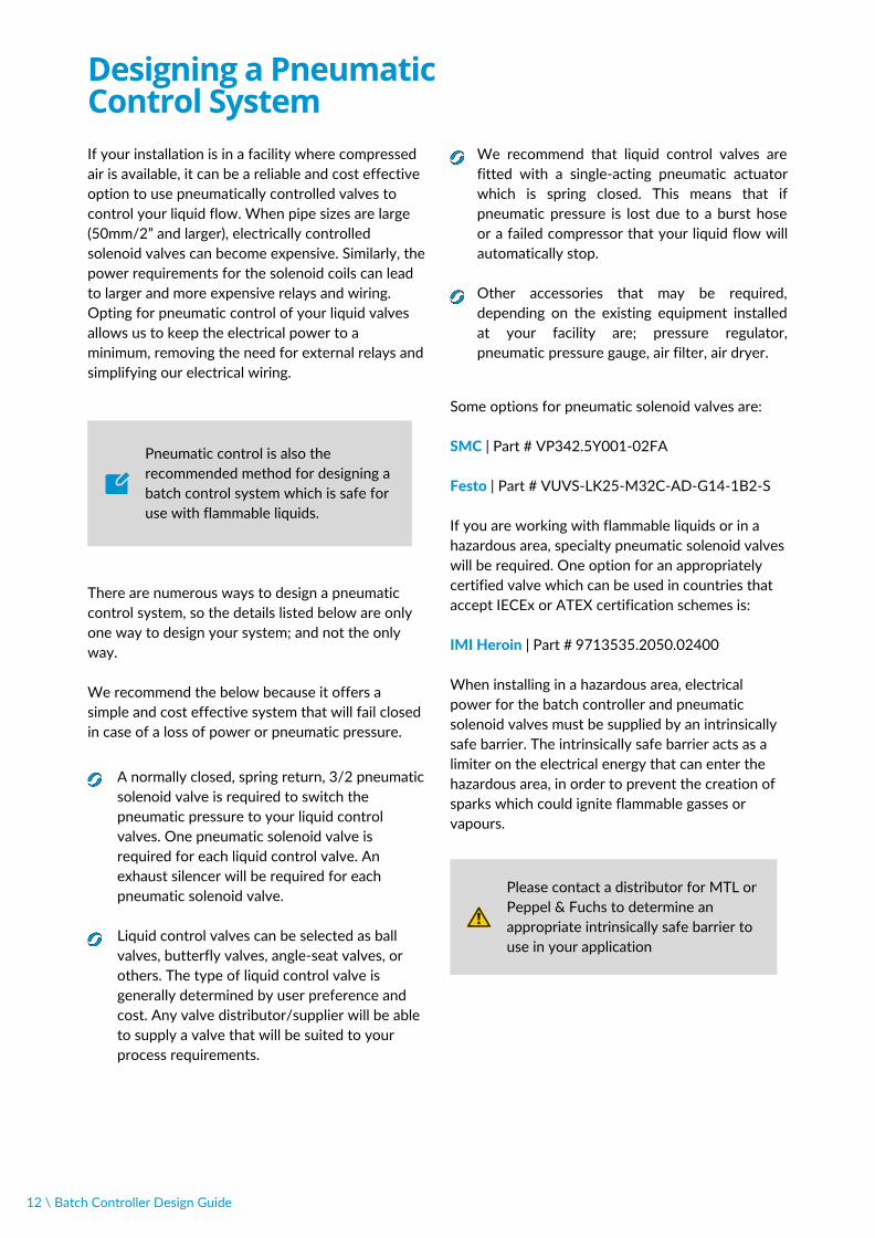
Designing a PneumaticControl SystemIf your installation is in a facility where compressedair is available, it can be a reliable and cost effectiveoption to use pneumatically controlled valves tocontrol your liquid flow. When pipe sizes are large(50mm/2” and larger), electrically controlledsolenoid valves can become expensive. Similarly, thepower requirements for the solenoid coils can leadto larger and more expensive relays and wiring.Opting for pneumatic control of your liquid valvesallows us to keep the electrical power to aminimum, removing the need for external relays andsimplifying our electrical wiring.
We recommend that liquid control valves arefitted with a single-acting pneumatic actuatorwhich is spring closed. This means that ifpneumatic pressure is lost due to a burst hoseor a failed compressor that your liquid flow willautomatically stop.
Other accessories that may be required,depending on the existing equipment installedat your facility are; pressure regulator,pneumatic pressure gauge, air filter, air dryer.
12 \ Batch Controller Design Guide
We recommend the below because it offers asimple and cost effective system that will fail closedin case of a loss of power or pneumatic pressure.
There are numerous ways to design a pneumaticcontrol system, so the details listed below are onlyone way to design your system; and not the onlyway.
Pneumatic control is also therecommended method for designing abatch control system which is safe foruse with flammable liquids.
Please contact a distributor for MTL orPeppel & Fuchs to determine anappropriate intrinsically safe barrier touse in your application

Electrical System Layout
Single stage system, using a 24VDC solenoid valve, coil power <10.8W
Batch Controller Design Guide / 13

Single stage system using a high-power DC solenoid valve, or AC solenoid valve
14 \ Batch Controller Design Guide

Dual stage system using 24VDC solenoid valves, coil power < 7.2W
Batch Controller Design Guide / 15

Dual stage system using a high-power DC solenoid valve, or AC solenoid valve
16 \ Batch Controller Design Guide

Single stage system using a pneumatic valve (safe area)
Batch Controller Design Guide / 17
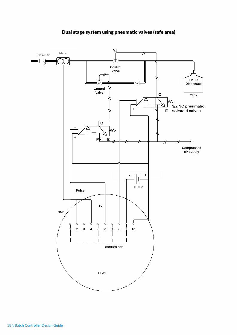
Dual stage system using pneumatic valves (safe area)
18 \ Batch Controller Design Guide
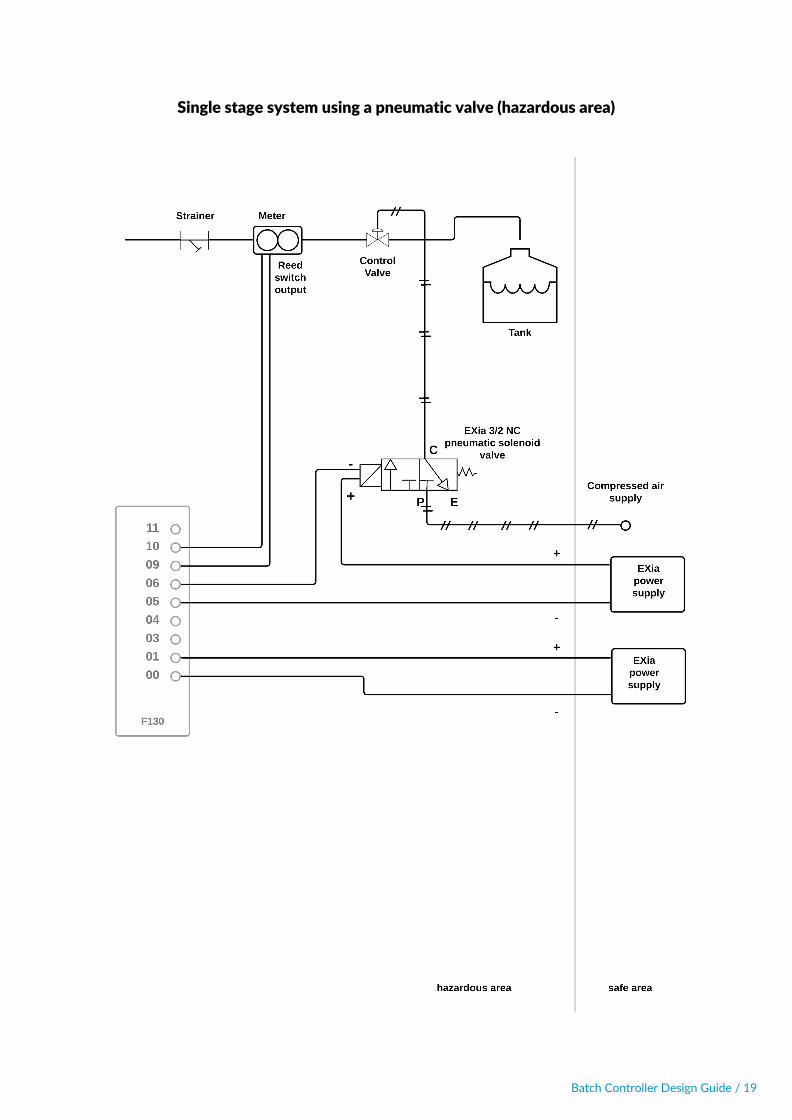
Single stage system using a pneumatic valve (hazardous area)
Batch Controller Design Guide / 19

Dual stage system using pneumatic valves (hazardous area)
20 \ Batch Controller Design Guide

GlossaryDirect acting solenoid valve – An electricallyactuated valve where the plunger that blocks theflow of liquid is directly moved by the solenoid coil.This type of solenoid valve does not require anydifference in pressure between inlet and outlet inorder to operate.
Indirect acting solenoid valve – An electricallyactuated valve which uses the pressure from thefluid to open and close the valve. Usually theelement which opens/closes the valve is adiaphragm or a piston. This type of valve requires apressure difference between inlet and outlet inorder to provide the force to open the valve seat.This type of valve requires less electrical power toopen, therefore higher liquid pressures and largervalves are possible with only a small solenoid coil.
Hazardous area – An area/location in which anexplosive atmosphere may be present. An explosiveatmosphere is defined as a mixture of air with aflammable or dangerous substance in the form ofgases, vapours, mist or dust. If ignition occurs in anexplosive atmosphere, due to a spark or a hotsurface, combustion spreads to the entire unburntmixture creating an explosion. Hazardous areasusually exist where flammable liquids, gases,vapours, or combustible dusts are used or stored.
Safe area – An area/location in which an explosiveatmosphere cannot be present. Safe areas usuallyexist when there is no handling/use/storage offlammable liquids, gases, vapours, or combustibledusts occurs.
Foot valve – A special design of check valve, ornon-return valve, which is designed for fitment tothe suction side of a pump (inlet side). Foot valvesprevent the draining of piping when the pump isoff, keeping the piping full of liquid, and preventingthe pump from losing prime.
Gravity fed system – Systems where the liquidpressure is provided by earth’s gravity acting on atank of liquid which is situated higher than theoutlet of the system.
Simple Apparatus – A simple apparatus is a passiveelectrical component such as a switch, junction box,resistors, thermocouple, or simple semiconductor,with well defined electrical properties and lowlevels of stored energy. A simple apparatus may beused in some hazardous area electrical systemswithout certification.
IECEx – The IEC system for certification ofequipment for use in explosive atmospheres. It usesassessments and standard specified by theInternational Electrotechnical Commission (IEC).IECEx is the accepted scheme for controlling thesafety of hazardous area electrical equipment invarious countries around the world, includingAustralia and New Zealand.
ATEX – "Appareils destinés à être utilisés enATmosphères EXplosives" (French for Equipmentintended for use in EXplosive ATmospheres). TheEuropean Union scheme for controlling the safetyof hazardous area electrical equipment.
FM – Factory Mutual, an insurance underwriter inthe United States of America which overseas thescheme for controlling the safety of hazardous areaelectrical equipment for the USA.
Intrinsically safe barrier – Intrinsically safe barriersare devices that limit the energy that is supplied toa circuit inside a hazardous area. Intrinsically safebarriers are a safety device that facilitates theconnection of intrinsically safe devices inside ahazardous area, to non-intrinsically safe circuits in asafe area.
EXia – An abbreviation for equipment which iscertified as intrinsically safe.
Batch Controller Design Guide / 21

© 2021, Great Plains Industries. All rights reserved.
Design guides, data sheet and other product information is available by emailing us or contacting your sales representative. Always consult the appropriatedocumentation before using any of our products.
Neither FLOMEC nor any of its affiliates makes any warranty, express or implied, including merchantability or fitness for use, or accepts any liability inconnection with recommended products from companies other than FLOMEC, related information or its use. Some applications of which FLOMEC'sproducts may be proposed to be used are regulated or restricted by applicable laws and regulations or by national or international standards and in somecases by FLOMEC's recommendation, including applications of food/feed, water treatment, medical, pharmaceuticals, and personal care.
The user must finally determine suitability of any information or products for any contemplated use in compliance with applicable law, the manner of useand whether any patents are infringed. The information and the products are for use by technically skilled persons at their own discretion and risk and doesnot relate to the use of this product in combination with any other substance or any other process. This is not a license under any patent or otherproprietary right.
All trademarks and registered trademarks are property of the companies that comprise Great Plains Industries.
Sydney, Australiawww.flomec.com.au 12/7-11 Parraweena RoadCaringbah, NSW 2229Australia
Wichita, United Stateswww.flomecmeters.com5252 E 36th ST NWichita, Kansas 67220United States