basis of design for sanitary sewer service village / town of red hook
TRANSCRIPT

December 2008
Basis of Design forSanitary Sewer Service
Village / Town of Red Hook
Dutchess County, New York
Prepared for:
VILLAGE OF RED HOOKTOWN OF RED HOOKDUTCHESS COUNTY WATER & WASTEWATER AUTHORITY
Dutchess CountyWater & Wastewater
Authority
Prepared by:
MEEo_
C.T. MALE ASSOCIATES, P.C.50 Century Hill Drive,
Latham, New York 121 10518.786.7400 FAX 518.786.7299
C.T. Male Project No: 08.8341© Copyright 2008
C.T. MALE ASSOCIATES, Y.C.

C.T. MALE ASSOCIATES, P.C.
Basis of Design for Sanitary Sewer ServiceVillage/Town of Red Hook
TABLEOF CONTENTSPage
1.0 INTRODUCTION - -1
2.0 EVALUATING WWTP SITE - 2 -
3.0 SIZING TREATMENT UNITS - 3 -
3.1
Influent Pump Station - 3 -
3.2
Fine Screen - 3 -
3.3
Grit Channel - 4 -
3.4
Flow Meter - 4 -
3.5
Activated Sludge Aerotor Package Plant - 5 -
3.6
Effluent Equalization - 6 -
3.7
Disc Filters - 6 -
3.8
UV Disinfection - 7 -
7 -3.9
Post Aeration
-
3.10 Discharge to Tributary to the Sawkill - 8 -
3.11 Sludge Holding - 8 -
4.0 FLOW DIAGRAMS -10 -
5.0 EMERGENCY OPERATIONS REQUIREMENTS -11 -
6.0 OPERATION AND MIANTENANCE REQUIREMENTS -12 -
6.0 OPERATION AND MIANTENANCE REQUIREMENTS -12 -
7.0 COST OPINIONS
- 13 -
8.0 ENVIRONMENTAL IMPACTS -14 -
9.0 PREVIOULSY INVESTIGATED ALTERNATIVES -15 -
9.1
Subsurface Disposal at Linden Avenue Site -15 -
9.2
Water Re-use and Subsurface Disposal Alternative - 15 -
FIGURES
WWTP Flow Diagram
Hydraulic Profile
C.T. MALE ASSOCIATES, P.C.
APPENDICES
APPENDIX A:
APPENDIX B:
APPENDIX C:
APPENDIX D:
APPENDIX E:
APPENDIX F:
APPENDIX G:
APPENDIX H:
APPENDIX I:
Influent Pump Station
Fine Screen
Aerotor Plant
Disc Filters
UV Disinfection
Sludge Holding
O&M Cost Opinions
Form E and Cost Opinions
Subsurface Disposal
C.T. MALE ASSOCIATES, P.C.
1.0 INTRODUCTION
C. T. Male Associates P.C. prepared a Facility Plan for providing sanitary sewer
service to portions of the Village and Town of Red Hook in August 2008. The Facility
Plan recommended a wastewater treatment plant (WWTP) located in the site of the
existing Red Hook Commons WWTP, which is a privately owned 25,000 gallons per
day (gpd) package WWTP.
For the proposed sewer district, a WWTP with a capacity of 85,000 gpd was proposed
with the following components:
• Influent pump station
• Fine screen
• Grit channel
• Flow meter
+ Activated sludge aerator package plant
• Effluent equalization
• Disc filter building
• UV disinfection
• Discharge to tributary to the Sawkill• Sludge Holding/Digestion
The purpose of this Basis of Design Report is to determine the following:
• Evaluating WWTP Site (land use, zoning, accessibility, future expansion,effluent requirements, receiving stream, site availability)
• Sizing Treatment Units+ Preparing Flow Diagrams• Outlining Emergency Operations Requirements+ Presenting Sludge Disposal Options• Operation and Maintenance Requirements• Updating Cost Opinions
• Considering Environmental Impacts
Additionally, the report will address and document alterative wastewater disposaloptions that were previously investigated including subsurface disposal.
1

C.T. MALE ASSOCIATES, P.C.
2.0 EVALUATING WWTP SITE
The existing WWTP at the Red Hook Commons site is a 25,000 gpd package activated
sludge plant with flow equalization, sand filtration and UV disinfection. The plant
was started in 2006 and currently treats approximately 6,000 gpd. The flow to the
WWTP comes from senior housing apartment units. Additionally, commercial and
residential development has been approved on the Red Hook Commons site, and the
developments will also discharge to the WWTP.
All of the wastewater from Red Hook Commons flows by gravity to a pump station
that serves as the influent pump station to the WWTP. The pump station's force main
is a 2-inch PVC pipe.
It has been agreed on principle by all parties that the proposed sewer district would
purchase the lot where the WWTP is located, and all wastewater trealment equipment
and the influent pump station.
The WWTP lot has been previously surveyed for wetlands, endangered species, and
archeological significance. Based on the mapped wetlands, the available useful land
was evaluated and there is sufficient room to construct a new WWTP and for a WWTP
that would treat the full build out (North and South Development and Red Hook
Schools).
C.T. MALE ASSOCIATES, P.C.
3.0 SIZING TREATMENT UNITS
3.1
Influent Pump Station
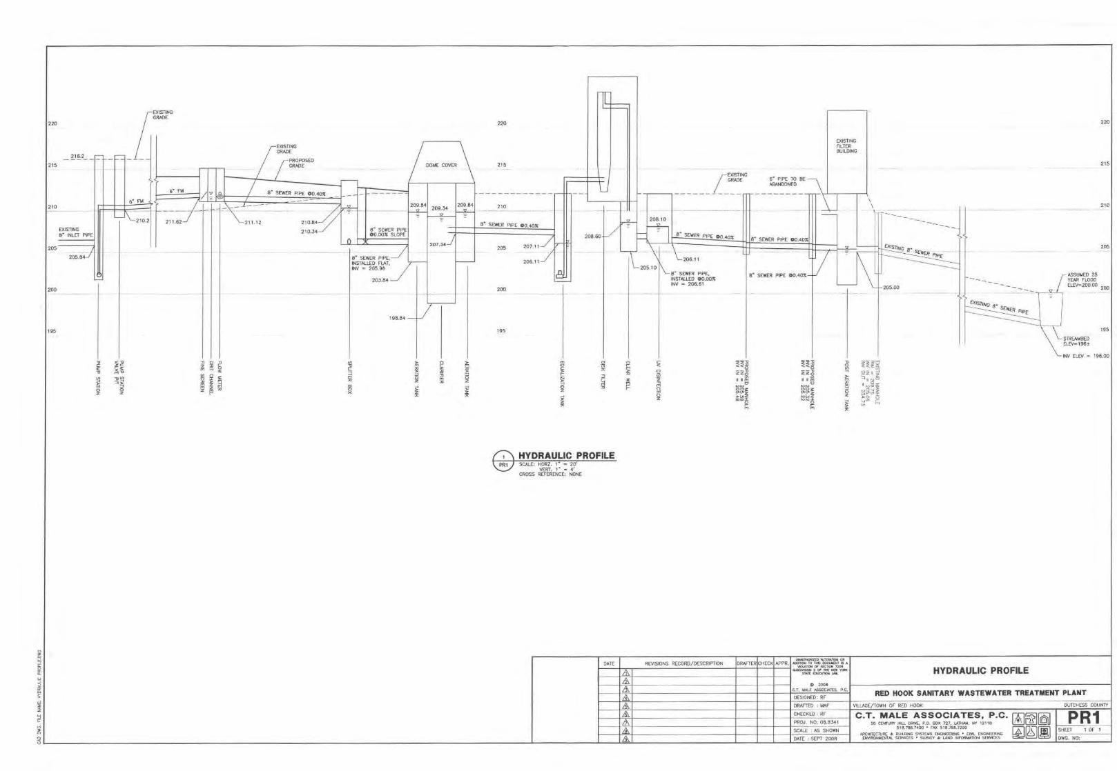
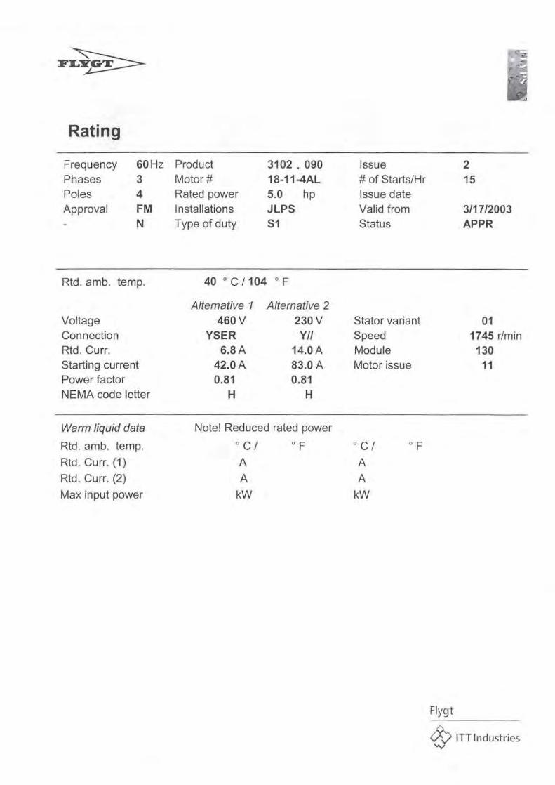
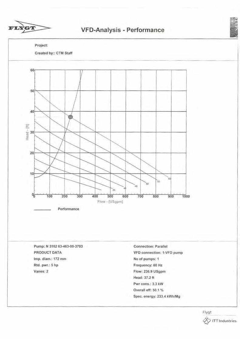
A proposed duplex submersible pumping system rated for 240 gpm at 38 ft TDH with
VFD controls and explosion-proof motors will serve as the influent pumping station.
See pump curve in Appendix A. The pump station would have a concrete valve pit for
the check valves and plug valves. The existing 4-foot diameter wet well will be re-
used with a new hatch for the new pumps.
The pump station will be sized for only the projected 85,000 gpd flow since future
flows would tie into the WWTP downstream of the pump station.
The force main from the pump station to the WWTP headworks would be 4-inch.
A NEMA 4X control panel and three phase power is needed.
A stand-by generator is recommended to provide uninterrupted pumping during
power outages.
Since the influent pumps will work off a VFD controls, the relatively small wet well
(4-diameter) is sufficient. With VFD controls, a pump is on when the influent flow is
entering the wet well and the speed of the pump adjusts to match the influent flow.
Thus, the wet well level remains approximately the same throughout the day.
One pump is sized to pump the peak flow at maximum speed thus the pump station
can operate with one pump out of service. During very low flow or no flow the pump
would shut off.
3.2
Fine Screen
A fine screen is recommended versus a grinder or comminutor to keep the non-
biodegradable materials out of the biological process. Fibrous materials re-seave
themselves back into "ropes" that can clog airlift pumps and will hang up on anything
that they can from the velocity control baffles in the Aerotor Plant, sludge holding
tank diffusers and piping, final clarifier weirs and scrapers, and even to tertiary filters.
-3
C.T. MALE ASSOCIATES, P.C.
In addition a fine screen with a 2 hp drive that operates intermittently (500 to 2,000
hours per year) versus a comminutor or grinder 3 hp drive that operates continuously
(8,760 hours per year) will save power costs.
A mechanical fine screen is recommended for this application. The fine screen is
located in a flow channel and physically prevents debris smaller than 3 mm from
passing through its stainless steel screen. As the debris builds up in the screen, the
water level rises in the channel and triggers the automatic "cleaning" mode of the
screen. The screen is racked and washed with the debris falling into a screw type
conveyor. The conveyor lifts the collected debris out of the flow channel and allows
the debris to be washed and dewatered on the way up to the trash hopper. By
washing and dewatering the debris, the weight is dramatically reduced and it allows
the debris to be disposed in the same manner as household trash.
A conceptual drawing of this screen is included in Appendix B.
3.3
Grit Channel
Grit removal facilities are needed to provide for removal of sand and grit or similar
debris that enters the sewer system. An outdoor channel-type that settles the grit by
gravity is recommended for this WWTP based on its low cost and simple operation.
With a channel-type grit removal system, the flow passes through the channel at
approximately 1 foot per second during the expected design flows. The 1 foot per
second velocity is slow enough to allow grit and sand to settle but fast enough to keep
organics in suspension for treatment in the activated sludge tanks. The material that
settles in the channel is periodically removed by shovel by the WWTP operator.
It is expected that less than a pound of grit will be collected per day.
Multiple grit channels are recommended to allow for future flows and ease of
maintenance.
3.4 Flow Meter
The flow meter that is used to monitor and document the amount of wastewater
treated needs to record a wide range of flows including future flows. An Extra Large
60 degree V Trapezoidal Flume provides a primary device that is good for the
4

C.T. MALE ASSOCIATES, P.C.
expected flow ranges 60 to 700 gpm and has good accuracy at low flows (0.5 to 60
gpm) .
The flow is calculated by measuring the depth of water as it passes through the flume.
To measure the depth of water an ultrasonic level senor is recommended. The flow
signal would be totalized and recorded on a 7-day circular chart.
3.5
Activated Sludge Aerotor Package Plant
The critical component of the WWTP is the biological treatment units. These treatment
units are required to remove the pollutants typically expected in a municipal
wastewater such as total suspended solids (TSS), biological oxygen demand (BOD),
and ammonia. Because the Red Hook plant will have strict effluent limits and will
need to operate with minimum labor and power cost, a packaged activated sludge
plant is recommended. The air supply for the activated sludge would be supplied by
aerators instead of blowers (Aerotor Plant).
The package aerator plant would have two aeration tank compartments, which
complies with Ten States Standards. Each aeration compartment would have a rotor
aerator that looks like a large brush. As the rotor turns it entraps air into the activated
sludge tank. The rotor aerators are controlled by variable speed drives to provide
operational control of the amount of dissolved oxygen in the system, which is a key
operational parameter for removing ammonia.
The two aeration tank compartments would discharge to a circular clarifier located at
the center of the plant. The clarifier provides a tank that promotes settling of the
activated sludge. The sludge settles to the bottom and clean/treated water flows over
the tank's weirs for further treatment.
The sludge from the bottom of the tank is pumped out by air lift pumps and returned
to the aeration tank to continue treating the influent wastewater. Air for the air lift
pump would be provided by one of the existing blowers at the site.
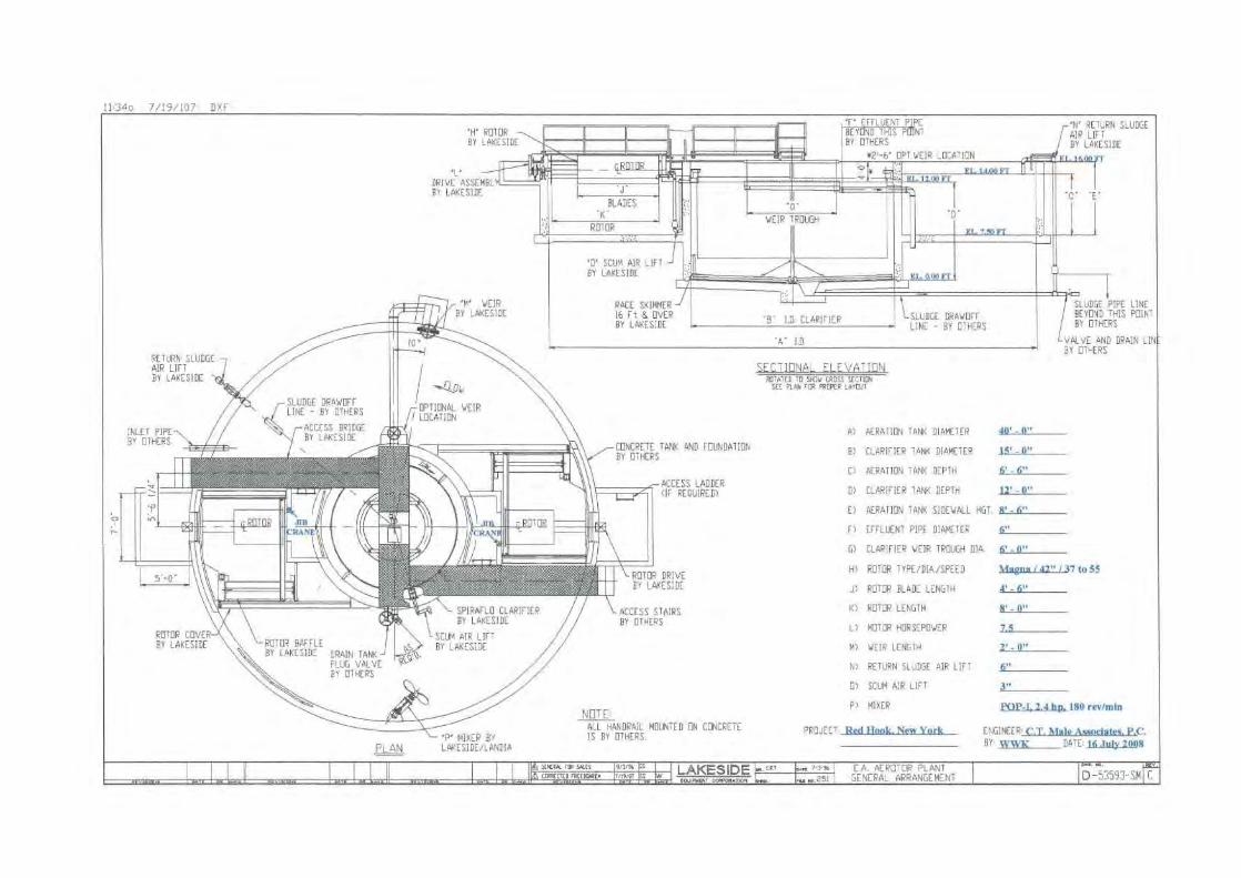
Appendix C has information on a typical aerator plant that could be used for this
project.
The plans would be constructed of in-ground concrete tanks and walls. Both circular
plants would be covered with fiberglass domes to facilitated winter operations.
-5
C.T. MALE ASSOCIATES, P.C.
To provide complete redundancy, two aerator plants are proposed. Each plant has
two aeration chambers, two aerators and one clarifier.
The design parameters for the two package aerator plants are as follows:
• Aeration volume 85,000 gallons (42,500 gallons each plant)
• Organic loading rate at 15 lbs of BOD per 1,000 cubic feet
• Hydraulic detention time of approximately 24 hours
• 1.4 lbs oxygen per lb of BOD removed
• 4.6 Ibs oxygen per lb of ammonia removed
• Operating dissolved oxygen levels of 2.0 mg/1
• MLSS 3,500 mg/ 1
• Food to Mass ratio 0.069
• Sludge produced 111 lbs per day
• Aeration channel depth at 6 feet and width at 11.5 feet
• Clarifier diameter at 15 feet and depth at 12 feet
• Hydraulic loading at peak hourly flow at 962 gal/ day sq ft
• Solids loading at average day at 14 lb/day sq ft
• Weir loading at peak hourly flow at 4,500 gal/day-ft
The package aerator plants are sized to produce the following effluent limits without
filtration filtration:
• BOD 5.0 mg/l
• TSS 10 mg/ l
• Ammonia 1.0 mg/ l
3.6
Effluent Equalization
After the treated wastewater flows through the treatment units, it will need to be
pumped to receive further treatment. The intermittent pumping station will provide
an ideal place to equalize the flow to reduce the size of the tertiary filters.
To provide for an efficient design only the peak flows (340,000 gpd) flows will be
equalized and only to peak hourly rates (170,000 gpd). To provide further
equalization would not reduce the size or cost of the down stream equipment (filters
and UV) but would add cost in requiring a larger equalization tank.
6
C.T. MALE ASSOCIATES, P.C.
3.7
Disc Filters
After secondary treatment with the aerator package plants, the wastewater would
require further filtration to meet the strict effluent limits (TSS 10 mg/l).
The disc filter system (one duty, one redundant) will filter a peak equalized flow of
170,000 gpd. The system is designed to provide solids removal to a final effluent
average concentration of 510 mg/l TSS and will operate at a loading rate in
accordance with Ten States Standards. The disc filter units will be constructed of
stainless steel.
The advantages of a disc filter versus traditional sand filters include ease of operation,
minimal maintenance, minimal equalization, less backwash requirements, and low
head loss.
The design parameters for the disc filters are:
• Peak Influent TSS at 25 mg/I
• Peak flow 175,000 gpd
Information on typical disc filters that could be used for this project is includedin Appendix D.
3.8
UV Disinfection
After the wastewater is treated for the typical municipal parameters (TSS, BOD, and
ammonia), the final step is to disinfect the wastewater. Disinfection with chlorine has
been the traditional method used, however a more environmentally friendly alterative
is to use ultraviolet (UV) light. UV light disinfects the water by killing or mutating at
the DNA level the bacterial, viruses and other microorganisms that are exposed to the
UV light. Once the DNA is mutated the organisms can not reproduce and thus pose
no health risk.
The design parameters for the UV system are as follows:
• Peak Hour Design Flow at 1.0 MGD
• UV Transmission at 65% (Minimum)
• Total Suspended Solids at 10 mg/I
7

C.T. MALE ASSOCIATES, P.C.
• Max Average Particle Size 30 microns
• Disinfection Limit: 200 fecal coliform per 100 ml
The UV channel would be approximately 12-inches wide and 18 feet long.
Information on the UV equipment is included in Appendix E.
3.9
Post Aeration
To ensure the expected limit of 7.0 mg/I of dissolved oxygen in the effluent is
maintained, post aeration is required. The existing post aeration tank will be kept and
used for the same purpose in the new WWTP.
The tank can be enlarged by removing the sand medial from the adjacent sand filter
and minor modifications to the existing steel tank.
Air will be supplied by the existing blowers.
3.10 Discharge to Tributary to the Sawkill
The proposed discharge stream is an intermittent stream that is an unnamed tributary
to the Saw Kill. C.T. Male confirmed with DEC that the discharge limits would be the
same as those at the existing WWTP and that the state would modify the discharge
permit for a larger WWTP (flows up to 500,000 gpd).
The proposed discharge limits that all the alternatives would have to meet are:
• BOD5 5 mg/ l
• TSS10mg/l
• Ammonia 1.1 mg/1 (Summer) 2.2 mg/1 (Winter)
• D.O.>7.0mg/l
• pH 6.5 to 8.5
• Fecal Coliform 200 No./100 ml
The proposed WWTP would not have total nitrogen limits or phosphorus limits. If
these limits are added in the future, the WWTP would have to be modified to achieve
those limits.

C.T. MALE ASSOCIATES, P.C.
3.11 Sludge Holding
The sludge that will be produced at the WWTP will be disposed off site by trucking
the sludge in liquid form. A contractor will be used for trucking and disposal of the
sludge, thus the cost of a sludge truck is not included in the project.
The waste sludge from the aeration tanks will be pumped to the sludge holding tank
as needed to maintain the operating parameters of the units (MLSS, MCRT, F-M, etc.).
It is expected that at capacity the aeration units will produce approximately 1,000
gallons of sludge per day. The sludge will be pumped to a sludge holding tank where
it will be aerated and settled to reduce the volume of sludge by digestion and
supernataning the clear liquid.
The existing activated sludge tank of the Red Hook Commons WWTP will be used as
the sludge holding tank. The existing steel tank has a capacity of 35,000 gallons, which
will provide over 30 days of detention time for the sludge. This amount of detention
time will allow for significant volatile (at least 38%) solids reduction and reduce the
amount of sludge that will need to be trucked off site.
The existing aeration tank has sufficient blower and diffuser capacity to provide
mixing in the sludge holding tank.
The supernatant or clear liquid removed from the sludge holding tank will be
pumped back to the influent of the aeration tanks.
Information on the existing aeration tank to be converted to be the sludge holding
tank is included in Appendix F.
9

C.T. MALE ASSOCIATES, P.C.
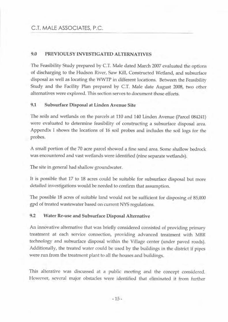
4.0 FLOW DIAGRAMS
A flow diagram for the proposed treatment process is enclosed in the Figure section of
this report. The diagram presents a schematic design. It is clear that all the proposed
equipment and tanks would fit on the proposed site within the available land and
there is room for future expansion.
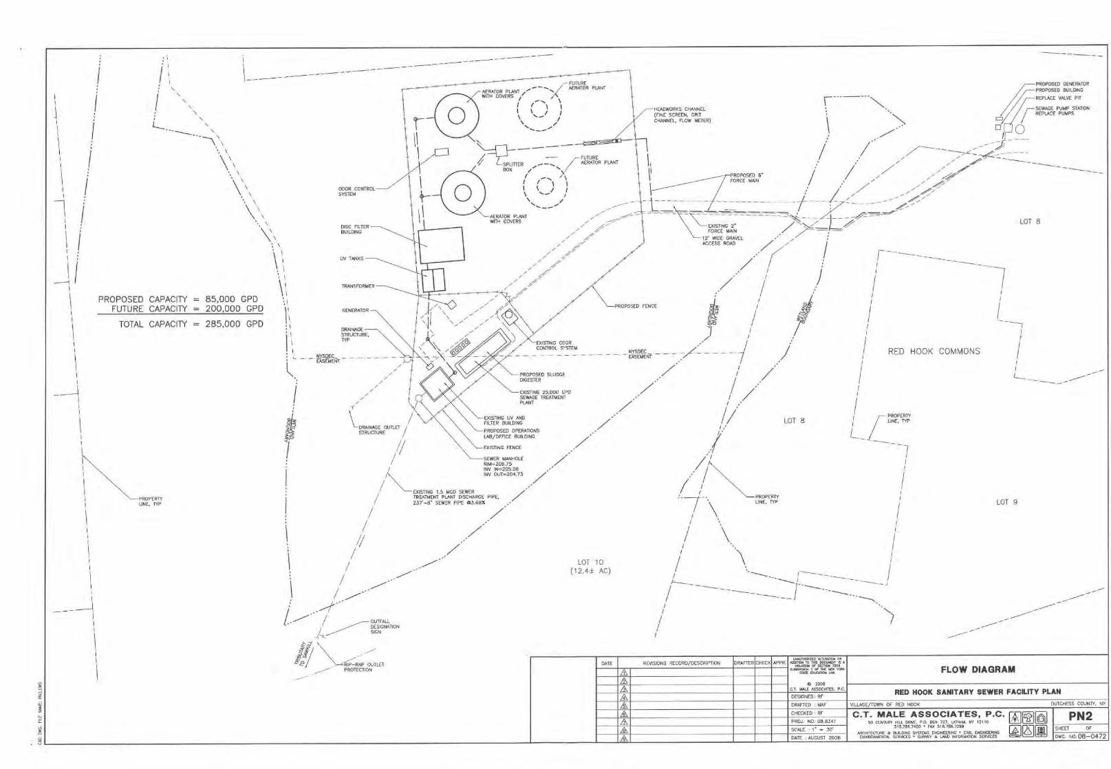
Additionally, a hydraulic profile has been developed for the proposed WWTP. The
hydraulic profile provides information as to how the wastewater would flow through
the treatment units. It identifies elevations for the tanks and at what stage of the
process the water is flowing by gravity and when it 's been pumped.
The influent pump station discharges at an elevation that allows the wastewater to
flow by gravity through the head works, aeration tanks, and clarifiers. The treated
wastewater will need to be pumped after the clarifiers to receive further filtration.
After filtration, the water flows through UV disinfection and post aeration by gravity
as well as final discharge to the stream.
C.T. MALE ASSOCIATES, P.C.
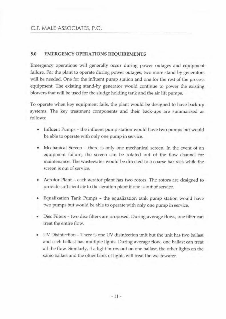
5.0 EMERGENCY OPERATIONS REQUIREMENTS
Emergency operations will generally occur during power outages and equipment
failure. For the plant to operate during power outages, two more stand-by generators
will be needed. One for the influent pump station and one for the rest of the process
equipment. The existing stand-by generator would continue to power the existing
blowers that will be used for the sludge holding tank and the air lift pumps.
To operate when key equipment fails, the plant would be designed to have back-up
systems. The key treatment components and their back-ups are summarized as
follows:
• Influent Pumps - the influent pump station would have two pumps but would
be able to operate with only one pump in service.
• Mechanical Screen - there is only one mechanical screen. In the event of an
equipment failure, the screen can be rotated out of the flow channel for
maintenance. The wastewater would be directed to a coarse bar rack while the
screen is out of service.
• Aerotor Plant - each aerator plant has two rotors. The rotors are designed to
provide sufficient air to the aeration plant if one is out of service.
• Equalization Tank Pumps - the equalization tank pump station would have
two pumps but would be able to operate with only one pump in service.
• Disc Filters - two disc filters are proposed. During average flows, one filter can
treat the entire flow.
• UV Disinfection - There is one UV disinfection unit but the unit has two ballast
and each ballast has multiple lights. During average flow, one ballast can treat
all the flow. Similarly, if a light burns out on one ballast, the other lights on the
same ballast and the other bank of lights will treat the wastewater.

C.T. MALE ASSOCIATES, P.C.
6.0 OPERATION AND MIANTENANCE REQUIREMENTS
The equipment and the treatment process selected is capable of automated operation
with limited operator maintenance. It is expected that on a routine day two hours of
operator attention should be provided.
The WWTP operator will be required to take samples of the influent and effluent flow
and check for parameters such as temperature, pH, ammonia and settable solids.
Additionally, samples from the aeration tank should be taken to test for settability and
MLSS concentration, dissolved oxygen.
Each major treatment component will be provided with an operation and
maintenance manual that will have a detail list of preventative maintenance items.
The WWTP operator will need to ensure that those items such as changing filters,
adding grease, changing oil, etc. are done at the manufactures recommended
intervals.
Appendix G has a detailed estimate for the cost of operation and maintenance for the
WWTP. Table 6-1 is a summary of the O&M costs.
Table 6-1WWTP Annual O&M Cost O pinions
Item Description CostElectric $24,600Labor $31,200Sludge Disposal $17,800Miscellaneous $18,90015% Contingency $14,000Total (2008 Dollars) $107,000Total (2010 Dollars) $118,000
C.T. MALE ASSOCIATES, P.C.
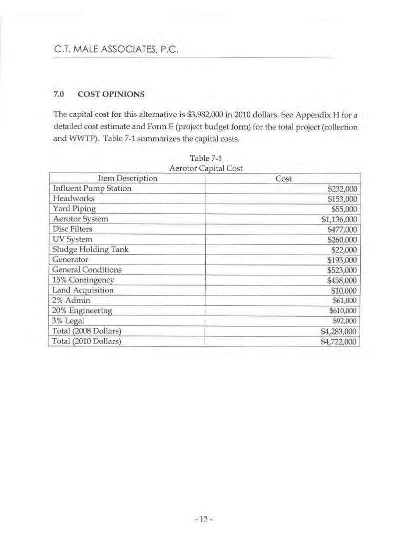
7.0 COST OPINIONS
The capital cost for this alternative is $3,982,000 in 2010 dollars. See Appendix H for a
detailed cost estimate and Form E (project budget form) for the total project (collection
and WWTP). Table 7-1 summarizes the capital costs.
Table 7-1Aerotor Capital Cost
Item Description CostInfluent Pump Station $232,000Headworks $153,000Yard Piping $55,000Aerotor System $1,136,000Disc Filters $477,000UV System $260,000Sludge Holding Tank $22,000Generator $193,000General Conditions $523,00015% Contingency $458,000Land Acquisition $10,0002% Admin $61,000
20% Engineering $610,000
3% Legal _
$92,000
Total (2008 Dollars) $4,283,000Total (2010 Dollars) $4,722,000

C.T. MALE ASSOCIATES, P.C.
8.0 ENVIRONMENTAL IMPACTS
An Environmental Report would be completed when the project progresses to the
design phase. The site for the proposed WWTP was developed in 2005-2006 for the
WW'IP that serves Red Hook Commons (senior housing). Thus, the site has been
studied and cleared for the intended use. Additionally, the previous project provided
recent wetland delineation, the site was found to have no adverse impact to
endangered species/critical habitats, etc. and historical resources were investigated.
The collection system is proposed to be located within the road right-of-way and is
expected to have minimal impacts, if any, to wetlands, farmland, forestland or
endangered species.
The collection system is expected to require a full archeological review to identify
historic sites and mapped documented structures that may be encountered during the
installation of the sewer pipes. It is expected that a Phase 1A/1B will be needed for the
entire collection system and that some Phase 2 studies may be required.
A Phase 1A (research with no field work) archeological study of the project site would
cost approximately $8,000. The cost of the follow-up Phase 1B study (field work with
shovel tests) would be determined based on the results of the Phase IA study.
Similarly, the cost for the Phase 2 studies (larger excavations) are unknown until the
Phase 1B work is complete.
C.T. MALE ASSOCIATES, P.C.
9.0 PREVIOULSY INVESTIGATED ALTERNATIVES
The Feasibility Study prepared by C.T. Male dated March 2007 evaluated the options
of discharging to the Hudson River, Saw Kill, Constructed Wetland, and subsurface
disposal as well as locating the WWTP in different locations. Between the Feasibility
Study and the Facility Plan prepared by C.T. Male date August 2008, two other
alternatives were explored. This section serves to document those efforts.
9.1
Subsurface Disposal at Linden Avenue Site
The soils and wetlands on the parcels at 110 and 140 Linden Avenue (Parcel 084241)
were evaluated to determine feasibility of constructing a subsurface disposal area.
Appendix I shows the locations of 16 soil probes and includes the soil logs for the
probes.
A small portion of the 70 acre parcel showed a fine sand area. Some shallow bedrock
was encountered and vast wetlands were identified (nine separate wetlands).
The site in general had shallow groundwater.
It is possible that 17 to 18 acres could be suitable for subsurface disposal but more
detailed investigations would be needed to confirm that assumption.
The possible 18 acres of suitable land would not be sufficient for disposing of 85,000
gpd of treated wastewater based on current NYS regulations.
9.2
Water Re-use and Subsurface Disposal Alternative
An innovative alternative that was briefly considered consisted of providing primary
treatment at each service connection, providing advanced treatment with MBR
technology and subsurface disposal within the Village center (under paved roads).
Additionally, the treated water could be used by the buildings in the district if pipes
were run from the treatment plant to all the houses and buildings.
This alterative was discussed at a public meeting and the concept considered.
However, several major obstacles were identified that eliminated it from further
-15-

C.T. MALE ASSOCIATES, P.C.
consideration. The obstacles included high cost and New York State' s environmental
rules and regulations do not allow for such a system.
K:\Projects \D88341\Admin\Basis of Dosing Rpt\Basis of Design rpt.doc
I
\L
PROPOSED CAPACITYFUTURE CAPACITY
TOTAL CAPACITY = 285,000 GPD
PROPERTYLINE, TYP
i
\
85,000 GPD= 200,000 GPO
PROPOSED GENERATORPROPOSED BUILDING
REPLACE VALVE PT
SEWAGE PUMP STATIONREPLACE PUMPS
LOT 8
I
1
1
1
PROPERTYr
LINE, TYP
L
7
LOT 8
PROPERTYLINE, TYP LOT 9
OUTFALLDESIGNATIONSIGN
1 -- --
-
1OAC)
LOT(12.4±
1
RED HOOK COMMONS
Gk"P ERE'
/
^^0
RIP RAP OUTLET/ PROTECTION
DATE REVISIONS RECORD/DESCRIPTION CHECKDRAFTER APPR.UNWTICRREO'HRFATEW CT
A2M010 10116 OOCIWENT A AMOULTON DC SECTION 7205
or THE
70FxSTAR MOA1OW NW, FLOW DIAGRAM
C 2008
DRAFTED MAE
VILLAGE/TOWN OF RED HOOK
DLTCHESS COUNTY, NY
RFCHECKED C.T. MALE ASSOCIATES, P.C. rifL PN2PROJ, NO: 08.8341 50 CENTURY HILL URNS, P.O. BOX 727. LATHN4 NY 12110
I
SCALE
1" = 30'515.7057400
FAX 515.755.7299I
SHEET
OF
DATE :AUGUST 20013ARCHITECTURE
SYSTEMS ENGINEERING
CIA ENGINEERINGEIMRCNMENONNENTAL SERVICES ' SURVEY N LANG
NG NGO INFORMATION SERVICES
d
LDWG. NO, 08-0472
C.T. MALE ASSOCIATES. P.C.
DESIGNED RFRED HOOK SANITARY SEWER FACILITY PLAN
220 220
215 DOME COVER
8" SEWER PIPE 00.40%
210
210.2 211,12
210.84
209.64v 209.34
v
209.84
215
215
"-EXISTINGGRADE
fi' PIPE TO BE_ _ ABANDONED -
210
210.34 8' SEWER PIPE00.00% SLOPE
195
200
205
8' SEWERINSTALLEDINV =
PIPE.-"FLAT,
205.96
203.84
207.34
205.108' SEWER PIPE.INSTALLED 00.00%INV - 206.61
200
C zzo2
0
T70,01
r0nO
tor,oZ 00>t0nt0 >ZZ
WW0
VINO 2m x
205
EXISTING8' sEwEk pipe
205.00
uWNNOA¢E0'N.TERAIOO ORDATE
REVISIONS RECORD/DESCRIPTION
DRAFTER CHECK APPR. 000000 00 ThO 000UWOR N AVIZADON OF SEFOI 20A
L18IX0ILN 2 THE NEW TO.s1ATT E0.GHOLR LVY. HYDRAULIC PROFILE
2008®NNE ASSOCUTE6, Pc'
DESIGNED: RF
RED HOOK SANITARY WASTEWATER TREATMENT PLANTDE
A DRAFTED : MAF
VILLAGE/TOWN OF RED HOOK
DUTCHESS COUNTY
®
CHECKED: RT
C.T. MALE ASSOCIATES, P.C. §'^I i,l
p RI _A PROJ. NO: 08 8341
50 CENTURY HILL DRNE, P.O. BOX 727. LATHAH, NY 12110
U ^'A
518.765.7400 • FAN 518.7883299-lLC1 SCALE : AS SHOWN
SHEET
1 OF 1ABCNR
BE RM E SYSTEMS ENGINEERING • MML ENGINEERINGDATE
L
C:J: SEPT 2008
ENNRONBENOHHENTAL SERVICES • SIAPIEY & LAND INFORMATION SERr1CE6
DWG NO;

APPENDIX A
Influent Pump Station

SYSTEM HEAD CURVE4" FM
0
50
100
150
200
250
300
350
400
450
500
FLOW, GPM
c=15- 0
-- c=120
- Pump
- Pump half speed
SYSTEM HEAD LOSS CALCULATIONRed Hook Influent Pump stationFORCE MAIN LENGTHROUGHNESS
C (old/new)PIPE
DfA (IN120
MINOR LOSSES K NO.Plug VALVE OPEN 0.31 1CHECK VALVE 1.70 190 ELBOW 0.51 445 DEG ELBOW 0.27 0TEE-trough 0.34 0TEE-branch 1.02 1EXPANSION 1.00 1
TOTAL
60
1.53
2.04
7.78
0.22
10.05
80
2.04
3.48
7.78
0.39
11.66
100
2.56
5.26
7.78
0.62
13.66
120
3.07
7.37
7.78
0.89
16.04
140
3.58
9.80
7.78
1.21
18.79
160
4.09
12.55
7.78
1.58
21.91
180
4.60
15.61
7.78
1.99
25.38
200
5.11
18.96
7.78
2.46
29.21
220
5.62
22.62
7.78
2.98
33.38
240
6.13
26.57
7.78
3.55
37.90260
6.64
30.81
7.78
4.16
42.75280
7.16
35.34
7.78
4.83
47.95300
7.67
40.15
7.78
5.54
53.47320
8.18
45.24
7.78
6.30
59.33340
8.69
50.61
7.78
7.11
65.51360
9.20
56.26
7.78
7.98
72.02380
9.71
62.18
7.78
8.89
78.84400
10.22
68.37
7.78
9.85
85.99
600 FT
4150
0.311.7
2.0400
1.021
6.07
3.43.53.84.45.05.96.98.19.5
11.012.614.516.418.520.823.225.728.4
203.84211.62
FLOWGPM
FRICTIONHEAD LOSS
FT0.000.270.97
STATICHEAD
FT7.787.787.78
MINORLOSSES
FT0.000.020.10
TDHFT
7.788.078.84
VELOCITYFPS
0
0.00
20
0.51
40
1.02
PSI
Wet Well ElevDISCHARGE ELEV
OLD PIPE
Syshead
Page 1

NEW PIPE
FLOW VELOCITY HEADFRICTION
LOSSSTATICHEAD
MINORLOSSES TDH
GPM FPS FT FT FT FT0 0.00 0.00 7.78 0.00 7.78
20 0.51 0.18 7.78 0.02 7.9840 1.02 0.64 7.78 0.10 8.5260 1.53 1.35 7.78 0.22 9.3580 2.04 2.30 7.78 0.39 10.48
100 2.56 3.48 7.78 0.62 11.88120 3.07 4.88 7.78 0.89 13.54140 3.58 6.49 7.78 1.21 15.47160 4.09 8.31 7.78 1.58 17.66180 4.60 10.33 7.78 1.99 20.10200 5.11 12.55 7.78 2.46 22.79220 5.62 14.97 7.78 2.98 25.73240 6.13 17.58 7.78 3.55 28.91260 6.64 20.39 7.78 4.16 32.33280 7.16 23.39 7.78 4.83 35.99300 7.67 26.57 7.78 5.54 39.89320 8.18 29.94 7.78 6.30 44.02340 8.69 33.50 7.78 7.11 48.39360 9.20 37.23 7.78 7.98 52.99380 9.71 41.15 7.78 8.89 57.82400 10.22 45.24 7.78 9.85 62.87
Syshead
Page 2

FLYGT PERFORMANCE CURVEPRODUCT
N P3102.090TYPE
MTDATE PROJECT CURVE NO ISSUE
2008-11-18 63-463-00-3703 21/1-LOAD
3/4-LOAD
1/2-LOAD RATED IMPELLER DIAMETER
POWER FACTOR
EFFICIENCY
MOTOR DATA
0.8185.0 %
POWER 5
hp 172 mm0.75 0.63 STARTING
85.0 % 83.5 % CURRENT ...
42
ARATEDCURRENT...
6.8
A
MOTOR
18-11-4ALIt STATOR
01YSERREV
11COMMENTS INLET/OUTLET
/ 4 inchRATED
1745 rpmTOT.MOM.OF
FREQ.
60 HzPHASES
3VOLTAGE
460 VPOLES
4IMP. THROUGHLET INERTIA ..
0.027
kgm2NO. OFBLADES
2 ---
GEARTYPE RATIO
---
W[hp]o 0
a-
z_rtrt O.c4
O3
LLLLw
wWcc
0-wD
O LLDUTY-POINT
FLOW[USgpm]
HEAD[ft]
POWER [hp]
EFF. [%]
NPSHre[fl]
0 ,k1
237
37.2
4.33
(
3.70)
51.6 (60.3)
9.6B.E.P.
484
26.7
5.17
(
4.42)
63.1
(73.9)
9.5
NPSHre o[ft]
[ft] °LLLLW
U,W
50 25 -I-
EFF.[o/o]
40 20 -
0W
-70
= 30 15 - 60
50
20 _ . \ 1 1 - 4 0
- 30
10 5- 20
- 10
0 0- 00
100
200
300
400
500
600
700
800
[USgpm]
FLOW
NPSHre = NPSH3% + min. operational marginF L Y G T H I B Curve
Performance with clear water and ambient temp 40 °C
FLYGT
Rating
Frequency
60 Hz Product
Phases
3
Motor #Poles
4
Rated power
Approval
FM
InstallationsN
Type of duty
3102 . 090
Issue
218-11-4AL
# of Starts/Hr
155.0
hp
Issue dateJLPS
Valid from
3/17/2003S1
Status
APPR
Rtd. amb. temp. 40 °C/104 °F
Voltage
Alternative 1
Alternative 2Stator variant460 V 230 V
Connection YSER Yll SpeedRtd. Curr. 6.8 A 14.0 A ModuleStarting current 42.0 A 83.0 A Motor issuePower factor 0.81 0.81NEMA code letter H H
Warm liquid data
Rtd. amb. temp.
Note! Reduced rated power
°C/
F°CI F
Rtd. Curr. (1) A A
Rtd. Curr. (2) A A
Max input power kW kW
011745 r/min
13011
ITT Industries
Flygt
Project:
Created by:: CTM Staff
VFD-Analysis - Performance
40
6
50
20
10
161UWL.
q'M
FIPMEINTW
..A‘n.,IRI
itah.,MOh1INANE 45
50
60ss
100
200
300
400
500
600
700
800
900
101 0
Flow - [USgpm]
Performance
Pump: N 3102 63-463-00-3703
Connection: Parallel
PRODUCT DATA
VFD connection: 1-VFD pump
Imp. diam.: 172 mm
No of pumps: 1Rtd. pwr.: 5 hp
Frequency: 60 HzVanes: 2
Flow: 236.9 USgpmHead: 37.2 ft
Pwr cons.: 3.3 kWOverall eff: 50.1 %Spec. energy: 233.4 kWh/Mg

Project:
Created by:: CTM Staff
PI4 GT
VFD-Analysis - Performance
661nUqpI
iUIwkh
ilia
qtilk
qrWklTihhhh\ITIrrAMM
4550
sr55
100
200
300
400
500
600
700
800
900
101
Flow - [USgpm]
Performance
Pump: N 3102 63-463-00-3703
Connection: Parallel
PRODUCT DATA
VFD connection: 1-VFD pump
Imp. diam.: 172 mm
No of pumps: 1
Rtd. pwr.: 5 hp
Frequency: 30 Hz
Vanes: 2
Flow: 69.5 USgpm
Head: 10.5 ft
Pwr cons.: 0.5 kW
Overall eff: 27.7 %
Spec. energy: 119.2 kWh/Mg
0
6
5
40
20
10
TT Industries
Flynt

APPENDIX B
Fine Screen

12MS PART No
B
C
D
F
H
-c 3/4' NPT WATER SUPPLY FUR SPRAY WASHw/LOCAL SHUT-OFF VALVE - BY OTHERS
STD 8'-5 1/2' 12'-4 1/4' 7'-7 1/4' 5'-11 1/2' 10'-2 3/4' 16'-7 1/2' 7'-2 1/2' 9'-3 5/8'
5 1 -0' MIN RECOMMENDED LENGTH
E'OF STRAIGHT CHANNEL
FLOW
,A,
OPTIONAL TUBE HEATERSEE NOTE 1
SOLENOID VALVES3 REDI D.
M
LOCAL NEMA 4/7/9CONTROL STATION
DUAL FLOATSWITCHES
DRIVE MOTOR
SECTION 'A-A'
CONTROL INTERCONNECTION DIAGRAM
EMERGENCY BYPASS GATE
TOP ELEV. 2' ABOVE MAX. W.L.
ALL CONDUIT AND WIRE CONNECTIONSBETWEEN CONTROL PANEL AND SCREENCOMPONENTS BY OTHERS,
NOTES'
1) WHEN HEAT SYSTEM IS TO BE SUPPLIED, CHANNEL WIDTHTO BE 24' IF CHANNEL DEPTH IS GREATER THAN 3'-6'.
2) CONTACT LAKESIDE FOR ANY ADDITIONAL REQUIREMENTSOR QUESTIONS.
3) KEEP TOP OF CENTER CHANNEL WALL AS LOW ASPOSSIBLE TO ALLOW EASE [IF CONSTRUCTION ANDMAINTENANCE.
4) WATER SUPPLY LINES AND ELECTRICAL CONNECTIONSTO BE FLEXIBLE or QUICK DISCONNECT TYPE TO ALLOWUNIT TO PIVOT BUT OF CHANNEL.
5) BE SURE UPSTREAM PIPING IS NOT SURCHARGEDAT MAX. W.L
6) FOR PROPER APPLICATION OF THIS PRODUCT REFERTO RMI-95, LAKESIDE SCREEN GENERAL DESIGN NOTES.
aav3$30N. DATE fl FKKD. 'REV xsxoNa
,/FIDM IVT
CVRSE PR RACK 9-27-07 ,SS/VN
REVISED TO CURRENT STANDARD 12-I8-06
5.F.DATE FNKD. NKD.3 DNAsavlaloN.
LAKESIDEEOUIPNENT CORPORATION
OA INHISSNYDER
a.m. 4-18-95R111*1081
nLL. NO. E4:N'ROI
RAPTOR°12' MICRO STRAINER
RED HOOK, NY D-51152-S K

APPENDIX C
Aerotor Plant
B
I.D. CLARIFIER SLUDGE DRAWUEFLINE - BY OTHERS
SLUDGE PIPE LINEBEYOND THIS POINTBY OTHERS
'A' LD VALVE AND DRAIN LIN:BY OTHERS
SEFINNAL ELEVATION_ROTATED TO SHOW CROSS SECTION
SEE PLAN F^ PROPER LAYOUT
A) AERATION TANK DIAMETER
40' - 0"
B) CLARIFIER TANK DIAMETER
1S'- 0"
CI AERATION TANK DEPTH
6' - 6"
D) CLARIFIER TANK DEPTH
12'-0"
E) AERATION TANK SIDEWALL MGT, R' -6"
F) EFFLUENT PIPE DIAMETER
6"
G) CLARIFIER WE]R TROUGH D]A
6'- 0"
H) ROTOR TYPE/DIA/SPEED
Magna/42" /37 to 55
J) ROTOR BLADE LENGTH
4'- 6"
K) ROTOR LENGTH
W-0"
L) MOTOR HORSEPOWER
7.5
M) WEIR LENGTH
z'-0"
NT RETURN SLUDGE AIR LIFT
6"
0) SCUM AIR LIFT
3"
P) MINER POP-I, 2.4 hp. 180 revlm in
PROJECT : Red Hook, New York ENGINEER: C:l'.Male Associates,fC.BY R'WK DATE, 16,bdy2008
GS7-3-96
CE.A. AEROTLR PLANT
GENERAL ARRANGEMENT D -53593-SM[OUIPMENT E-ORPORATONCORRECTED FREERDARD9
sra^as_^ramfPa^
LAKESIDE
llllllllllllllllllllllllllllllllllllllll
11 : 34a 7/19/107 DXF
Page 1 of 28
LAKESIDE E.A. AEROTOR PROCESS
DATE:
I 3-Aug-08
PROJECT:
Red Hook, New York - REV 1
ENGINEER:
C.T..M.ale Associates, P.C.
SALES REPRESENTATIVE: Lange, Inc.
I. DESIGN SUMMARY
VALUE
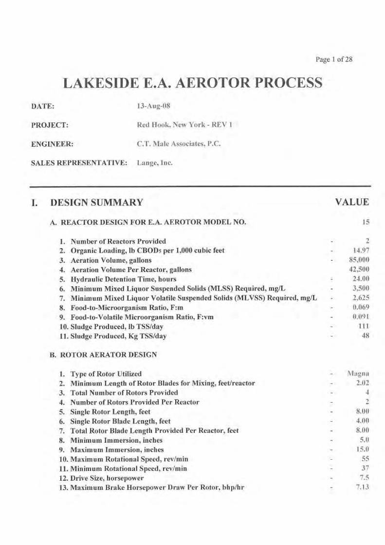
A. REACTOR DESIGN FOR E.A. AEROTOR MODEL NO. 15
1. Number of Reactors Provided 2
2. Organic Loading, lb CBOD5 per 1,000 cubic feet
- 14.97
3. Aeration Volume, gallons 85,000
4. Aeration Volume Per Reactor, gallons 42,500
5. Hydraulic Detention Time, hours
- 24.00
6. Minimum Mixed Liquor Suspended Solids (MLSS) Required, mg/L 3,500
7. Minimum Mixed Liquor Volatile Suspended Solids (MLVSS) Required, mg/L
- 2,625
8. Food-to-Microorganism Ratio, F:m
- 0.069
9. Food-to-Volatile Microorganism Ratio, F:vm
- 0.091
10. Sludge Produced, lb TSS/day
- 111
11. Sludge Produced, Kg TSS/day
- 48
B. ROTOR AERATOR DESIGN
1. Type of Rotor Utilized Magna
2. Minimum Length of Rotor Blades for Mixing, feet/reactor 2.02
3. Total Number of Rotors Provided 4
4. Number of Rotors Provided Per Reactor 2
5. Single Rotor Length, feet 8.00
6. Single Rotor Blade Length, feet 4.00
7. Total Rotor Blade Length Provided Per Reactor, feet 8.00
8. Minimum Immersion, inches 5.0
9. Maximum Immersion, inches 15.0
10. Maximum Rotational Speed, rev/min 55
11. Minimum Rotational Speed, rev/min 37
12. Drive Size, horsepower 7.5
13. Maximum Brake Horsepower Draw Per Rotor, bhp/hr 7.13

Page 2 of 28
C. OXYGEN DELIVERY REQUIREMENTS
1. Average Day Design Year Without Denitrification Credit
a. Actual Oxygen Transfer Required, lb 02/day
b. Standard Oxygen Transfer Required, lb 02/day
c. Standard Oxygen Transfer Required, lb 02/hour
d. Rotor Immersion, inches
e. No. Rotors at 55 rev/minf.
No. Rotors at 37 rev/min
g. Standard Oxygen Transfer Provided, lb 02/hour
h. Power Draw, brake horsepower/houri. Oxygen Transfer Efficiency, lb 02/bhp
j. Design Year Annual Average Power Cost, $
2. Average Day Design Year With Denitrification Credit
a. Actual Oxygen Transfer Required, lb 02/day
b. Actual Oxygen Transfer Recovered Via Denitrification, -lb 02/dayc. Adjusted Actual Oxygen Transfer Required, lb 02/day
d. Standard Oxygen Transfer Required, lb 02/day
e. Standard Oxygen Transfer Required, lb 02/hour
f. Rotor Immersion, inches
g. No. Rotors at 55 rev/min
h. No. Rotors at 37 rev/mini. Standard Oxygen Transfer Provided, lb 02/hour
j. Power Draw, brake horsepower/hour
k. Oxygen Transfer Efficiency, lb 02/bhp
I. Design Year Annual Average Power Cost, $
m. Design Year Annual Average Power Cost Saving, $n. Power Savings Present Worth at
4 % for
20 years
a. Actual Oxygen Transfer Required, lb 02/day
b. Standard Oxygen Transfer Required, lb 02/day
c. Standard Oxygen Transfer Required, lb 02/hour
d. Rotor Immersion, inches
e. No. Rotors at 55 rev/min
f.
No. Rotors at 37 rev/min
g. Standard Oxygen Transfer Provided, lb 02/hour
h. Power Draw, brake horsepower/houri. Oxygen Transfer Efficiency, lb O2/bhp
- 386
636
- 26.5- 8.2
1- 1
13.3
- 4.13.23
- 9,205
- 386- -66
- 320- 527
22.0
- 11.8- 0
2
- 11.0- 3.35- 3.29
7,482
- -1,723
- -23,417
386
63626.5
11.2
- 0
13.3
4.3
3.11
3. Operation With One Rotor Out of Service at Average Day
Conditions

Page 3 of 28
4. Operation at Maximum Day Conditions
a. Actual Oxygen Transfer Required, lb 02/day
b. Standard Oxygen Transfer Required, lb 02/day
c. Standard Oxygen Transfer Required, lb 02/hour
d. Rotor Immersion, inches
e. No. Rotors at
55
rev/min
f. No. Rotors at
37
rev/ming. Standard Oxygen Transfer Provided, lb 02/hour
h. Power Draw, brake horsepower/hour
i. Oxygen Transfer Efficiency, lb 02/bhp
D. REACTOR DIMENSIONS
1. Sidewater Depth, feet
2. Reactor Channel Width, feet
3. Reactor Cross Sectional Area, square feet4. Reactor Outer Diameter, feet
5. Reactor Inner Diameter, feet
6. Single Reactor Surface Area, square feet
7. Single Reactor Total Volume, gallons
S. E.A. Aerotor Process Total Volume, gallons
E. FINAL CLARIFIER DESIGN
1. Clarifier Diameter, feet
2. Clarifier Sidewater Depth, feet
3. Effluent Weir Length, feet
4. Hydraulic Loadinga. Peak Hourly (Qphww), gal/day-sq ftb. Average Day (Qave) Flow, gal/day-sq ft
5. Solids Loadinga. Peak Hourly (Qphww), lb/day-sq ftb. Average Day (Qave) Flow, lb/day-sq ft
6. Effluent Weir Loadinga. Peak Hourly (Qphww), gal/day-ftb. Average Day ((Nye) Flow, gal/day-ft
F. ADJUSTABLE EFFLUENT WEIR DESIGN
1. Number of Adjustable Weirs Per Reactor
2. Length of Adjustable Weir, feet
3. Weir Type
694
1,144
47.7
10.2
2
0
23.9
- 7.7
3.11
6.00
11.50
69.00
40.00
17.00
1,030
- 46,211
92,422
15.00
12.00
- 37.70
962
241
24.6
14.0
- 4,509
1,127
1
2.00
Gate
Page 4 of 28
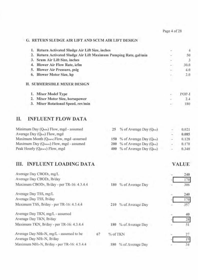
G. RETURN SLUDGE AIR LIFT AND SCUM AIR LIFT DESIGN
1.
Return Activated Sludge Air Lift Size, inches 42.
Return Activated Sludge Air Lift Maximum Pumping Rate, gal/min
- 503.
Scum Air Lift Size, inches
- 34.
Blower Air Flow Rate, icfm 30.05.
Blower Air Pressure, psig
- 4.06.
Blower Motor Size, hp
- 2.0
H. SUBMERSIBLE MIXER DESIGN
1. Mixer Model Type POP-I2.
Mixer Motor Size, horsepower
- 2.43.
Mixer Rotational Speed, rev/min 180
II.
INFLUENT FLOW DATA
Minimum Day (Qm;h) Flow, mgd - assumed
25
% of Average Day (Qave)
- 0.021Average Day (Qave) Flow, mgd
- 0.085Maximum Month (Qaww) Flow, mgd -assumed
150
% of Average Day (Qave)
- 0.128Maximum Day (Qn,ww) Flow, mgd - assumed
200
% of Average Day (Qave) 0.170Peak Hourly (Qphww) Flow, mgd
401)
% of Average Day (Qave)
- 0.340
III. INFLUENT LOADING DATA
VALUE
Average Day CBOD5, mg/L 240Average Day CBOD5, lb/day 170Maximum CBOD5, lb/day - per TR-16: 4.3.4.4 180 % of Average Day 306
Average Day TSS, mg/L 240Average Day TSS, lb/day 1701Maximum TSS, lb/day - per TR-16: 4.3.4.4 210 % of Average Day 357
Average Day TKN, mg/I, - assumed 40Average Day TKN, lb/day 281Maximum TKN, lb/day - per TR-16: 4.3.4.4 180 % of Average Day 51
Average Day NH3-N, mg/L - assumed to be 67 % of TKN 27Average Day NH3-N, lb/day 191Maximum NH3-N, lb/day - per TR-16: 4.3.4.4 180 % of Average Day 34
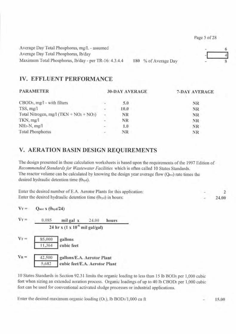
Page 5 of 28
Average Day Total Phosphorus, mg/L - assumedAverage Day Total Phosphorus, lb/day
Maximum Total Phosphorus, lb/day - per TR-16: 4.3.4.4
ISO % of Average Day
641
8
IV. EFFLUENT PERFORMANCE
PARAMETER
30-DAY AVERAGE
7-DAY AVERAGE
CBODs, mg/l - with filters
-
5.0
NRTSS, mg/I
10.0
NRTotal Nitrogen, mg/1 (TKN + N02 + N03)
NR
NRTKN, mg/1
-
NR
NRNH3-N, mg/l
-
1.0
NRTotal Phosphorus
NR
NR
V. AERATION BASIN DESIGN REQUIREMENTS
The design presented in these calculation worksheets is based upon the requirements of the 1997 Edition ofRecommended Standards . or Wastewater Facilities which is often called 10 States Standards.The reactor volume can be calculated by knowing the design year average flow (Q,e) rate times thedesired hydraulic detention time (Ohod).
Enter the desired number of E.A. Aerotor Plants for this application:
- 2Enter the desired hydraulic detention time (Ohyd) in hours:
- 24.00
VT =
Qave X (Ohyd/24)
VT =
0.085
mil gal x
24.00
hours
24 hr x (1 x 10 -6 mil gal/gal)
Vr=
Vx =
85,00011,364
42,500
5,682
gallonscubic feet
gallons/E.A. Aerotor Plantcubic feetlE.A. Aerotor Plant
10 States Standards in Section 92.31 limits the organic loading to less than 15 lb BODs per 1,000 cubicfeet when sizing an extended aeration process. Organic loadings of up to 40 lb CBODs per 1,000 cubicfeet can be used for conventional activated sludge processes or industrial applications.
Enter the desired maximum organic loading (OL), lb BOD5/1,000 cu ft
-
15.00
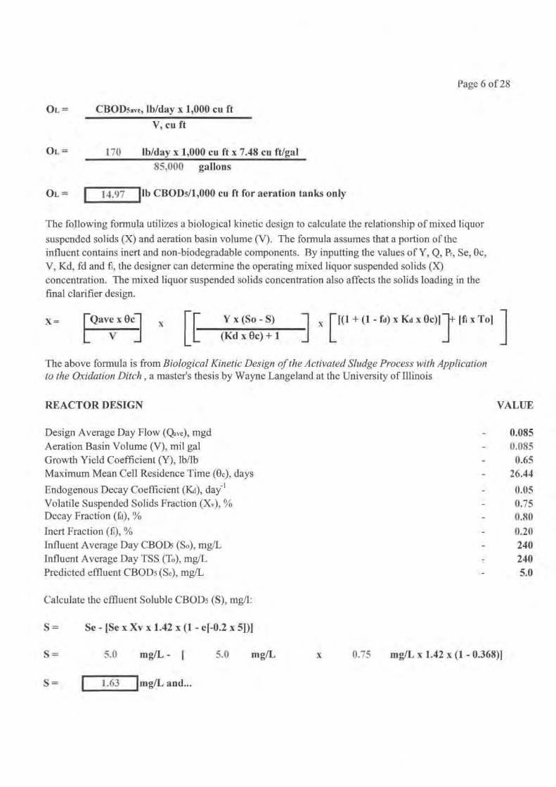
Page 6 of 28
Ot. =
CBODsave, lb/day x 1,000 cu ft
V, cu ft
OL =
170
lb/day x 1,000 cu ft x 7.48 cu ft/gal85,000
gallons
14.97
1 lb CBODs/1,000 cu ft for aeration tanks onlyOL =
The following formula utilizes a biological kinetic design to calculate the relationship of mixed liquor
suspended solids (X) and aeration basin volume (V). The formula assumes that a portion of theinfluent contains inert and non-biodegradable components. By inputting the values of Y, Q, Pr, Se, 0c,V, Kd, fd and f, the designer can determine the operating mixed liquor suspended solids (X)concentration. The mixed liquor suspended solids concentration also affects the solids loading in thefinal clarifier design.
x= [Qave x eel x Yx(So - S) x [(1+(1-fd)xKdXOc)] [fi x To]
V (Kdxec)+1
The above formula is from Biological Kinetic Design of the Activated Sludge Process with Applicationto the Oxidation Ditch , a master's thesis by Wayne Langeland at the University of Illinois
REACTOR DESIGN
VALUE
Design Average Day Flow (Qave), mgd
0.085Aeration Basin Volume (V), mil gal
0.085Growth Yield Coefficient (Y), lb/lb
0.65Maximum Mean Cell Residence Time (00, days
26.44
Endogenous Decay Coefficient (Ki), day -l 0.05Volatile Suspended Solids Fraction (Xv), %
0.75
Decay Fraction (fd), %
0.80Inert Fraction (f), %
0.20Influent Average Day CBODs (So), mg/L
240Influent Average Day TSS (To), mg/L
240Predicted effluent CBODs (Se), mg/L
5.0
Calculate the effluent Soluble CBODs (S), mg/1:
S =
Se - [Se x Xv x 1.42 x (1 - e[-0.2 x 5])]
S =
5.0
mg/L - [
5.0
mg/L
x
0.75
mg/L x 1.42 x (1 - 0.368)]
S= I 1.63 J mg/L and...

Page 7 of 28
X= Qave xOC
V
(1)
x [[(1 +(1 -fd)xKdx0c)] +[fixTo]
Calculate the first part of the equation (1):
Qave X 0C
0.085
mgd x
26
days
V
0.085
mil gal
Qave x 0c
26.44
V
Calculate the second part of the equation (2):
Y x (So - S)
=
0.65
lb/lb x ( 240 mg/L
1.63
mg/L)
(Kd x 0c) + 1
0.05
day -1 x
26 days
+
1
(YxSo)-S
66.73
mg/L
(Kd x 0c) + 1
Calculate the third part of the equation (3):
1 + (1 - fa) x Ka x Oc =
1 +
(1 -
0,80 )
x
0.05 day-' x
26 days
1+(1-fd)xKdxOc = 1.2644
Calculate the fourth part of the equation (4):
fi x To =
0.20
x
240 mg/L
fix To=
48.00 mg/L
X=
Qave x Oc
xV
(1)
X =
26.44
X=
3,500 mg/L
Y x (So s)
[(1 + (1 - fd) x Ka x Oc)] + [fi x To]
KdxOc)+1
(2)
x [ (
66.73
mg/L
x
1.2644 ) +
48.00
mg/L ]
Page 8 of 28
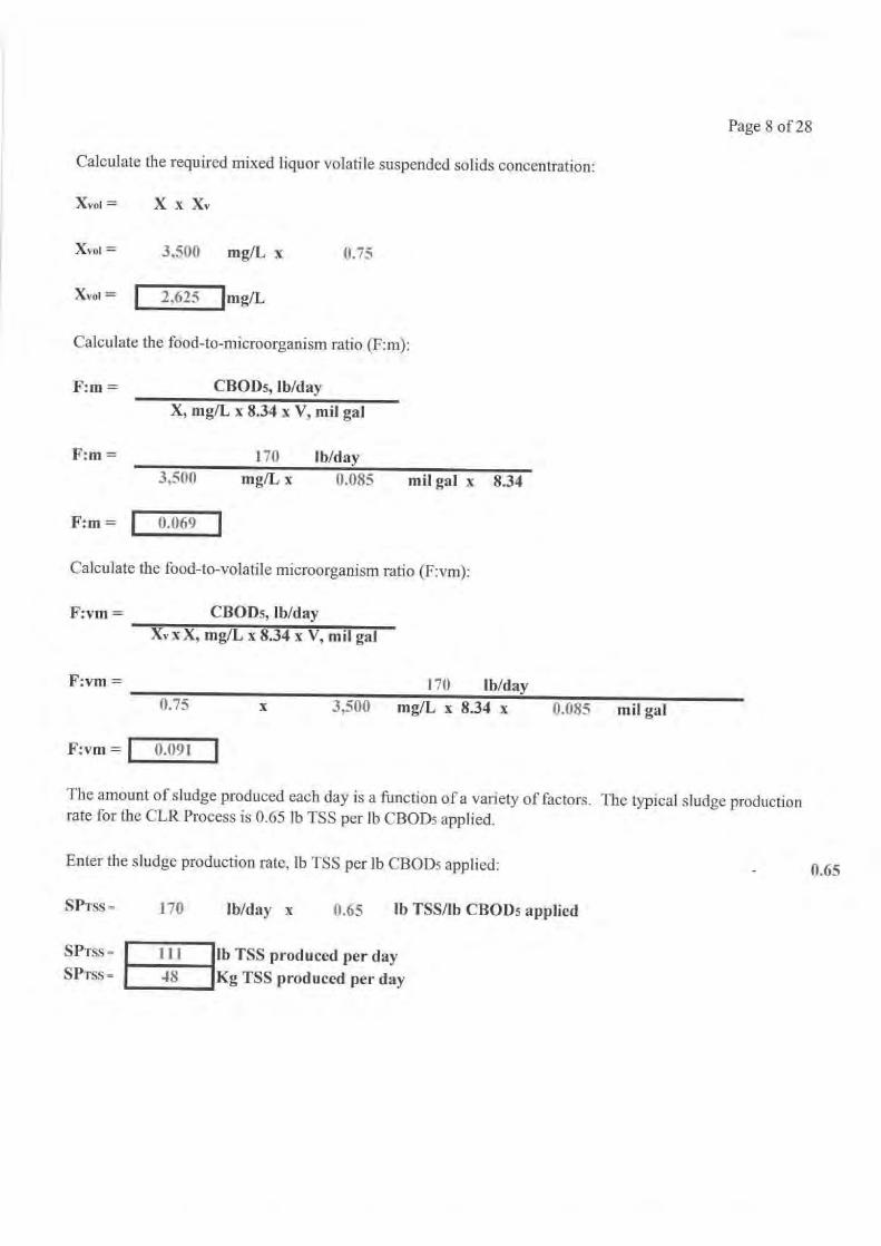
Calculate the required mixed liquor volatile suspended solids concentration:
Xvoi =
X x Xv
Xvoi =
3,500
mg/L x
0.75
Xvoi = 1 2,625 Img/L
Calculate the food-to-microorganism ratio (F:m):
F:m = CBOD5, lb/day
X, mg/L x 8.34 x V, mil gal
F:m =
170
lb/day
3,500
mg/L x
0.085
mil gal x 8.34
F:m =
0.069
Calculate the food-to-volatile microorganism ratio (F:vm):
F:vm =
CBOD5, lb/dayXv x X, mg/L x 8.34 x V, mil gal
F:vm =
170
lb/day0.75
x
3,500
mg/L x 8.34 x
0.085
mil gal
F:vm = r 0.091.
The amount of sludge produced each day is a function of a variety of factors. The typical sludge productionrate for the CLR Process is 0.65 lb TSS per lb CBOD5 applied.
Enter the sludge production rate, lb TSS per lb CBOD5 applied:
_
0.65
SPrss= 170
lb/day
x
0.65
lb TSS/lb CBOD5 applied
SPrss = I 111 lb TSS produced per daySPi'ss 48 Kg TSS produced per day

Page 9 of 28
VI. FINAL CLARIFIER DESIGN
The final clarifier is the "heart" of any biological process. Lakeside uses our state-of-the-art SpirafloClarifier for biological processes because it has been proven to be from 2 to 4 times more hydraulicallyefficient than a center-feed clarifier.
Clarifier sizing is based upon both hydraulic loading rate and solids loading rate according to TenStates Standards. For the CLR Process the peak hourly hydraulic loading rate should be limited to1,000 gal/day-sq ft. For conventional activated sludge processes the hydraulic loading should be limitedto 1,200 gal/day-sq ft. The solids loading should be limited to no more than 35 lb/sq ft-day basedupon the maximum RAS flow rate (RASmax) and the peak day flow (Qmww) rate to the clarifiers.The maximum MLSS to the final clarifiers should be either 3,500 mg/1 or the maximum calculatedMLSS value (X).
For plants with industrial contributions such as dairies or where chemical addition is being added for
phosphorus removal, we suggest decreasing the hydraulic loading to 800 gal/day-sq ft.
DESIGN DATA VALUE
Number of Final Clarifiers _
2
Maximum Hydraulic Loading Rate, gal/day-sq ft -
1,000Maximum Solids Loading, lb/sq ft-day -
35Maximum Mixed Liquor Suspended Solids (X), mg/1 3,500Maximum Return Activated Sludge (RAS) Flow, % of Qave -
150
DESIGN CALCULATIONS
Calculate the clarifier diameter based upon the hydraulic loading rate:
112
Qphww, gal/day x 4Number of Final Clarifiers x Hydraulic Loading Rate, gal/day-sq ft x
1/20.340
mgd x 1,000,000 gal/mgd
x
42
units
x
1,000
gallday-sq ft x n
D=
D=
D= feet
Calculate the minimum clarifier diameter based upon the solids loading rate:
D =
(Qmww, mgd + RASmax, mgd) x MLSS, mg/1 x 8.34 x 4Number of Final Clarifiers x Solids Loading Rate, lb/day-sq ft x it
112
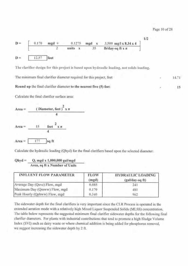
Page 10 of 28
D =
0.170
mgd +
0.1275 mgd x
3,500 mg/l x 8.34 x 42
units x
35
lb/day-sq ft x n
D=
12.57
feet
The clarifier design for this project is based upon hydraulic loading, not solids loading.
The minimum final clarifier diameter required for this project, feet
Round up the final clarifier diameter to the nearest five (5) feet:
Calculate the final clarifier surface area:
2Area =
( Diameter, feet) x n
4
2Area =
15
feet x ar4
Area =
177
sq ft
Calculate the hydraulic loading (Qhyd) for the final clarifiers based upon the selected diameter:
Qhyd = Q, mgd x 1,000,000 gallmgdArea, sq ft x Number of Units
INFLUENT FLOW PARAMETER FLOW(mgd)
HYDRAULIC LOADING(gallday-sq ft)
Average Day (Qave) Flow, mgd 0.085 241Maximum Day (Qmww) Flow, mgd 0.170 481Peak Hourly (Qphww) Flow, mgd 0.340 962
The sidewater depth for the final clarifiers is very important since the CLR Process is operated in theextended aeration mode with a relatively high Mixed Liquor Suspended Solids (MLSS) concentration.The table below represents the suggested minimum final clarifier sidewater depths for the following final
clarifier diameters. For plants with industrial contributions that tend to promote a high Sludge VolumeIndex (SVI) such as dairy waste or where chemical addition is being added for phosphorus removal,we suggest increasing the sidewater depth by 2 ft.
112
14.71.
15

Page 11 of 28
FINAL CLARIFIER DIAMETER MINIMUM SIDE WATER DEPTH(feet) (feet)
D< 40
40<D<7512
14
Based upon the final clarifier diameter for this project, the suggest minimum sidewater depth shouldbe not less than
12
feet.
Enter the desired final clarifier sidewater depth:
Calculate the final clarifier volume:
V =
Surface Area, sq ft x Sidewater Depth, feet
V =
177
sq ft x
12
feet
12.00
V= cu ft
Calculate the hydraulic detention time (DT) for the final clarifiers based upon the selected diameter andsidewater depth:
DT =
Volume, cu ft x 7.48 gal/cu ft x 24 hr/day x Number of UnitsFlow, mgd x 1,000,000 gallmgd
INFLUENT FLOW PARAMETER FLOW(mgd)
DETENTION TIME(hours)
Average Day (Qave) Flow, mgd 0.085 9.0Maximum Day (Qmww) Flow, mgd 0.170 4.5Peak Hourly (Qphww) Flow, mgd 0.340 2.2
Ten States Standards requires that the final clarifier weir loading rate be less than 20,000 gal/day-ft for
plants with an average flow of less than 1.0 mgd and less than 30,000 gallday-ft for plants with an average
flow of greater than 1.0 mgd. The final clarifier maximum weir loading rate calculation is based upon thepeak hourly flow rate which is
0.340
mgd for this application. Based upon an average flow of0.085
mgd, the maximum weir loading is not to exceed
20,000
gallons per day per linearfeet of weir.
Based upon a final clarifier diameter of
15
feet selected for this project, the minimumtotal weir length is 37.70 feet. Weir configuration for this size clarifier is
round
. This weirconfiguration has a 6.00 foot
diameter
dimension. Calculate the peak weir loadingrate for the final clarifiers based upon the selected diameter:

Page 12 of 28
WL =
Peak Hourly (Qphww) Flow, mgd x 1,000,000Weir Length, feet x Number of units
WL =
0.340 mgd x 1,000,000 gal/mgd37.7 feet
x 2
units
WL= 4,509 1 gal/day-ft
VII. E.A. AEROTOR REACTOR DESIGN
The E.A. Aerotor Process is offered in standard designs based upon the final clarifier diameter and the
required reactor volume. Select the desired Model Number based upon the final clarifier design and thedesired reactor volume:
The required volume calculated, gallons
E.A. AEROTOR MODEL NO. FLOWRANGE(gal/day)
CLRDIAMETER
(feet)10 30,000 3015 60,000 4020 110,000 5025 170,000 6030 250,000 7035 325,000 8040 450,000 9045 575,000 100
Therefore, the suggested E.A. Aerator Model Number is:
Enter the desired E.A. Aerotor Model Number:
The outer diameter of the selected E.A. Aerotor Model Number aeration reactor (feet) is:
Enter the final clarifier wall thickness (feet):
Calculate the required aeration reactor sidewater depth necessary for the aeration reactor volumeof
42,500
gallons or
5,682
cubic feet.
Depth =
Volume, cu ft2
2(Aeration Reactor Diameter, ft) - (Final Clarifier Outer Diameter, ft)
x n/4
42,500
15
15
40.00
1.00

Page 13 of 28
Depth =
5,682
cu ft
40
ft2 -
17
ft 2 ] xrr14
Depth =
5.52
feet
Round the calculated aeration reactor sidewater depth up to the nearest 0.50 ft increment:
-
6.00
Calculated the actual aeration reactor volume:
2
2V =
(Aeration Reactor Diameter, ft) - (Final Clarifier Outer Diameter, ft) ] x n/4 x Depth, ft
2
2V =
40
ft
-
17
ft x a/4 x
6.00
ft
V= 6,178
46,211cubic feetgallons
VIII. ROTOR LENGTH REQUIRED FOR MIXING
The bulk liquid velocity in a reactor varies with rotor type, rotor length, rotor speed, rotor immersion,reactor geometry, reactor depth, reactor material, velocity control baffles and their inclination (0 to 60degrees from horizontal) and obstructions in the reactor. The minimum Magna Rotor length for mixingis based a maximum of 1 ft of rotor length per 21,000 gallons. For reactor volumes of less than 60,000gallons, reduce the length to 1 ft per 16,000 gallons.
Calculate the minimum required rotor length for mixing based upon the calculated reactor volume:
MIN. ROTOR LENGTH =
MIN. ROTOR LENGTH =
MIN. ROTOR LENGTH =
Reactor Volume, gallonsgal/ft rotor x number of reactors
85,000 gallons21,000
gallft
x
2
reactors
2.0.2
feet of rotor per reactor
The maximum single rotor length (feet) for the selected E.A. Aerotor Plant Model Number is:
8.00
Page 14 of 28
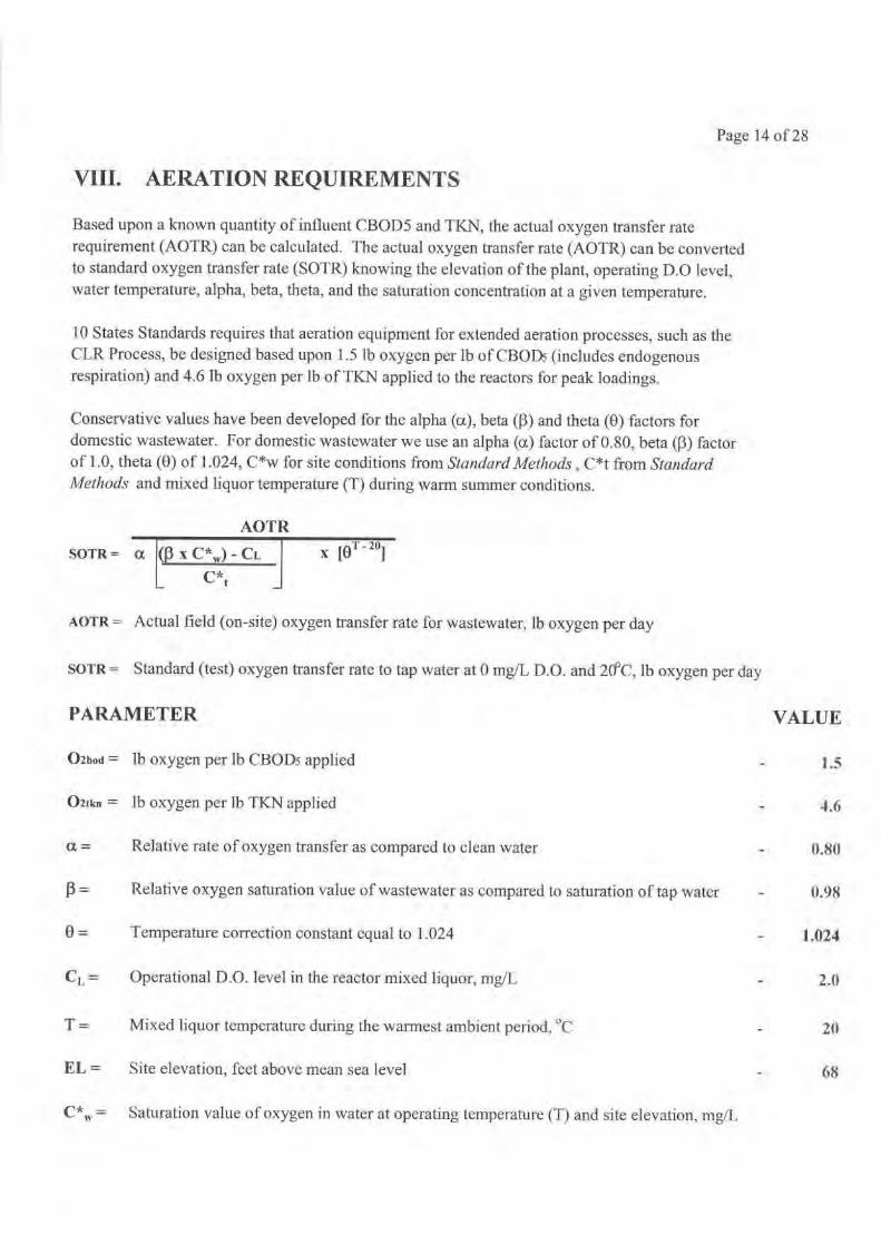
VIII. AERATION REQUIREMENTS
Based upon a known quantity of influent CBOD5 and TKN, the actual oxygen transfer raterequirement (AOTR) can be calculated. The actual oxygen transfer rate (AOTR) can be convertedto standard oxygen transfer rate (SOTR) knowing the elevation of the plant, operating D.O level,water temperature, alpha, beta, theta, and the saturation concentration at a given temperature.
10 States Standards requires that aeration equipment for extended aeration processes, such as theCLR Process, be designed based upon 1.5 lb oxygen per lb of CBODs (includes endogenousrespiration) and 4.6 lb oxygen per lb of TKN applied to the reactors for peak loadings.
Conservative values have been developed for the alpha (a), beta (f3) and theta (0) factors fordomestic wastewater. For domestic wastewater we use an alpha (a) factor of 0.80, beta (f3) factorof 1.0, theta (0) of 1.024, C*w for site conditions from Standard Methods , C*t from StandardMethods and mixed liquor temperature (T) during warm summer conditions.
AOTR
SOTR = a (f3 x C* µ,) - CL
x [0T - 20j
L
C*t
AOTR = Actual field (on-site) oxygen transfer rate for wastewater, lb oxygen per day
SOTR = Standard (test) oxygen transfer rate to tap water at 0 mg/L D.O. and 20°C, lb oxygen per day
PARAMETER
O2boa = lb oxygen per lb CBODs applied
_
O2fkn = lb oxygen per lb TKN applied
_
a =
Relative rate of oxygen transfer as compared to clean water
f3 =
Relative oxygen saturation value of wastewater as compared to saturation of tap water
0 =
Temperature correction constant equal to 1.024
Cy, =
Operational D.O. level in the reactor mixed liquor, mg/I,
T =
Mixed liquor temperature during the warmest ambient period, °C
EL =
Site elevation, feet above mean sea level
_
68
C'', = Saturation value of oxygen in water at operating temperature (T) and site elevation, mg/L
2.0
20

Page 15 of 28
C*w, =
CSE X C*
C*t
CSE =
Saturation value of oxygen in water at 20°C at site elevation, mg/L
C* =
Saturation value of oxygen in water at operating temperature, mg/L
C*t =
Saturation value of oxygen used at standard conditions, mg/L
C*, =
9.08
mg/L x
9.09
mg/L
9.081
9.091
- 9.092
9.08
1.024
I
1.000
20
°C ]
AOTRSOTR =
0.80 [ C 0.98 x
9.08
mg/L ] -
2.0 mg/L
x
1.0009.092 mg/L
SOTR =
1.65
x AOTR for normal operation with 2.0 mg/L mixed liquor D.O.
Calculate AOTR and SOTR for each design parameter:
AOTR = (lb CBODs
x
1.5
) +
(lb TKN
x
4.6 )
Enter the desired number rotor aerators per reactor for this project:
-
2Standard rotor length, feet:
-
8.00Enter the desired rotor blade length, feet:
4.00Select the desired rotor maximum rotational speed, rev/min:
-
55Select the desired rotor minimum rotational speed, rev/min:
37Enter the cost of power, S/kilowatt-hour - published state average
0.145Enter the EPAct minimum motor efficiency, %
-
0.895
Average Day
Oxygen Delivery With One (1) Rotor Out of Service
Enter the desired nixed liquor D.O. (Ci.P) for operation with one rotor out of service, mg/L
-
2.00
SOTR =
1.65
x AOTR for operation with one rotor out of service
Page 16 of 28
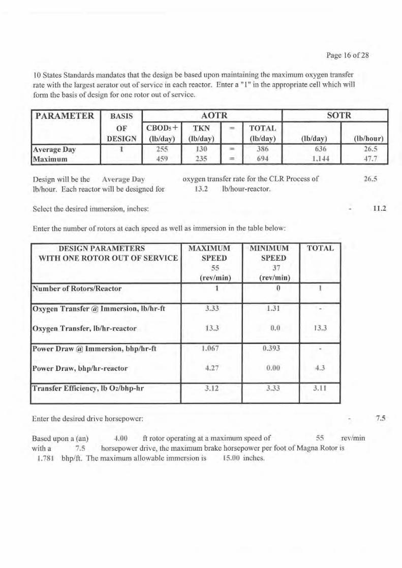
10 States Standards mandates that the design be based upon maintaining the maximum oxygen transferrate with the largest aerator out of service in each reactor. Enter a "1" in the appropriate cell which willform the basis of design for one rotor out of service.
PARAMETER BASIS AOTR SOTR
OFDESIGN
CBOD5 +
(lb/day)TKN
(lb/day)= TOTAL
(lb/day) (lb/day) (lb/hour)
Average Day 1 255 13€1 = 386 636 26.5Maximum 459 235 = 694 1,144 47.7
Design will be the Average Daylb/hour. Each reactor will be designed for
oxygen transfer rate for the CLR Process of13.2
lb/hour-reactor.26.5
11.2Select the desired immersion, inches:
Enter the number of rotors at each speed as well as immersion in the table below:
DESIGN PARAMETERS MAXIMUM MINIMUM TOTALWITH ONE ROTOR OUT OF SERVICE SPEED SPEED
55 37(rev/min) (rev/min)
Number of Rotors/Reactor 1 U 1
Oxygen Transfer @ Immersion, lb/hr-ft 3.33 1.31 -
Oxygen Transfer, lb/hr-reactor 13.3 0.0 13.3
Power Draw @ Immersion, bhp/hr-ft 1.067 0.393
Power Draw, bhp/hr-reactor 4.27 0.00 4.3
Transfer Efficiency, lb 02/bhp-hr 3.12 3.33 3.11
Enter the desired drive horsepower:
-
7.5
Based upon a (an)
4.00
ft rotor operating at a maximum speed of
55
rev/min
with a
7.5
horsepower drive, the maximum brake horsepower per foot of Magna Rotor is1.781 bhp/ft. The maximum allowable immersion is
15.00 inches.
Page 17 of 28
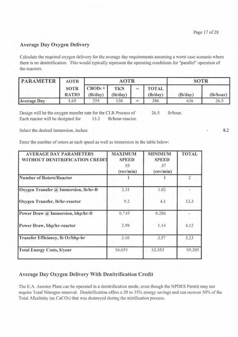
Average Day Oxygen Delivery
Calculate the required oxygen delivery for the average day requirements assuming a worst case scenario wherethere is no denitrification. This would typically represent the operating conditions for "parallel" operation ofthe reactors.
PARAMETER AOTR
SOTRRATIO
AOTR SOTRCBOD;+(lb/day)
TKN(lb/day)
= TOTAL(lb/day) (lb/day) (lb/hour)
Average Day 1.65 255 130 - 386 636 26.5
Select the desired immersion, inches:
26.5
lb/hour.
8.2
Design will be the oxygen transfer rate for the CLR Process ofEach reactor will be designed for
13.2
lb/hour-reactor.
Enter the number of rotors at each speed as well as immersion in the table below:
AVERAGE DAY PARAMETERS MAXIMUM MINIMUM TOTALWITHOUT DENITRIFICATION CREDIT SPEED SPEED
55 37(rev/min) (rev/min)
Number of Rotors/Reactor 1. 1 2
Oxygen Transfer @ Immersion, lb/hr-ft
Oxygen Transfer, lb/hr-reactor
2.31
9.2
L02
4.1
-
13.3
Power Draw @ Immersion, bhp/hr-ft
Power Draw, bhp/hr-reactor
0.745
2.98
0.286
1.14 4.12
Transfer Efficiency, lb 02/bhp-hr 3.10 3.57 3.23
Total Energy Costs, Slyear S6,651 S2,553 59,205
Average Day Oxygen Delivery With Denitrification Credit
The E.A. Aerotor Plant can be operated in a denitrification mode, even though the NPDES Permit may notrequire Total Nitrogen removal. Denitrification offers a 20 to 35% energy savings and can recover 50% of theTotal Alkalinity (as CaCO3) that was destroyed during the nitrification process.
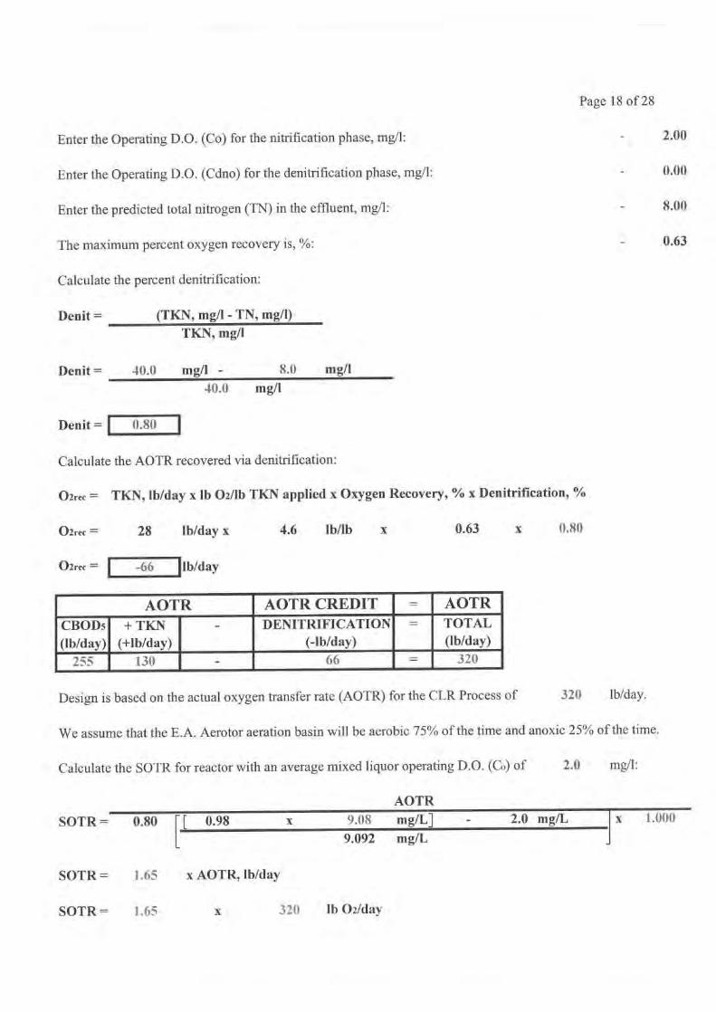
Page 18 of 28
Enter the Operating D.O. (Co) for the nitrification phase, mg/1: 2.00
Enter the Operating D.O. (Cdno) for the denitrification phase, mg/1: 0.00
Enter the predicted total nitrogen (TN) in the effluent, mg/l: 8.00
The maximum percent oxygen recovery is, %: 0.63
Calculate the percent denitrification:
Denit = (TKN, mg/l - TN, mg/1)TKN, mg/l
Denit =
40.0 mg/l
- 8.0 mg/1
40.0 m g/l
Denit = 0.80
Calculate the AOTR recovered via denitrification:
02rec = TKN, lb/day x lb 02/lb TKN applied x Oxygen Recovery, % x Denitrification, %
02rec =
28
lb/day x
4.6
lb/lb
x
0.63
x
0.80
02rec =
-66
lb/day
AOTR AOTR CREDIT = AOTR
CBOD5(lb/day)
+ TKN(+lb/day)
- DENITRIFICATION(-lb/day)
TOTAL(lb/day)
2 130 - 66 = 320
Design is based on the actual oxygen transfer rate (AOTR) for the CLR Process of
320
lb/day.
We assume that the E.A. Aerotor aeration basin will be aerobic 75% of the time and anoxic 25% of the time.
Calculate the SOTR for reactor with an average mixed liquor operating D.O. (Co) of
2.0
mg/l:
AOTR
[ 0.98
x
9.08
mg/L]
-
2.0 mg/L
x
1.000
9.092 mg/L
SOTR =
1.65
x AOTR, lb/day
SOTR = 0.80
SOTR =
1.65
x
320
lb 02/day
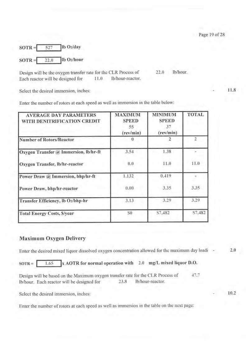
Page 19 of 28
SOTR = 527 lb 02/day
lb 02/hourSOTR = 22.0
Design will be the oxygen transfer rate for the CLR Process of
22.0
lb/hour.
Each reactor will be designed for
11.0
lb/hour-reactor.
Select the desired immersion, inches:
Enter the number of rotors at each speed as well as immersion in the table below:
AVERAGE DAY PARAMETERSWITH DENITRIFICATION CREDIT
MAXIMUMSPEED
MINIMUMSPEED
TOTAL
55 37(rev/min) (rev/min)
Number of Rotors/Reactor 0 2 2
Oxygen Transfer @ Immersion, lb/hr-ft
Oxygen Transfer, lb/hr-reactor
3.54
0.0
1.38
11.0
-
11.0
Power Draw @ Immersion, bhp/hr-ft
Power Draw, bhp/hr-reactor
1..132
0.00
0.419
3.35
-
3.35
Transfer Efficiency, lb 02/bhp-hr 3.13 3.29 3.29
Total Energy Costs, $lyear SO S7,482 57,482
Maximum Oxygen Delivery
Enter the desired mixed liquor dissolved oxygen concentration allowed for the maximum day loadi
SOTR =
1.65
x AOTR for normal operation with 2.0 mg/L mixed liquor D.O.
Design will be based on the Maximum oxygen transfer rate for the CLR Process of
47.7
lb/hour. Each reactor will be designed for
23.8
lb/hour-reactor.
Select the desired immersion, inches:
Enter the number of rotors at each speed as well as immersion in the table on the next page:
11.8
2.0
10.2
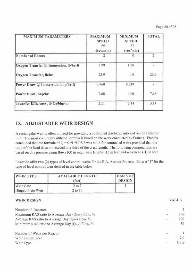
Page 20 of 28
MAXIMUM PARAMETERS MAXIMUM MINIMUM TOTALSPEED SPEED
55 37(rev/min) (rev/min)
Number of Rotors 2 0 2
Oxygen Transfer @ Immersion, lb/hr-ft 2.99 1.20 -
Oxygen Transfer, lb/hr 23.9 0.0 23.9
Power Draw @ Immersion, bhp/hr-ft 0.960 0.349 -
Power Draw, bhp/hr 7.68 0.00 7.68
Transfer Efficiency, lb 02/bhp-hr 3.11 3.4-1 3.11
IX. ADJUSTABLE WEIR DESIGN
A rectangular weir is often utilized for providing a controlled discharge into and out of a reactorunit. The most commonly utilized formula is based on the work conducted by Francis. Francisconcluded that the formula of Q = 0.*L*H^3/2 was valid for contracted weirs provided that theratio of the head does not exceed one-third of the crest length. The following computations arebased on this premise using flows (Q) in mgd, weir lengths (L) in feet and weir head (H) in feet.
Lakeside offer two (2) types of level control weirs for the E.A. Aerotor Process. Enter a "1" for thetype of level control weir desired in the table below:
WEIR TYPE AVAILABLE LENGTH(feet)
BASIS OFDESIGN
Weir GateHinged Plate Weir
2 to 72 to 15
l
WEIR DESIGN VALUE
Number of ReactorsMaximum RAS ratio to Average Day (-max) Flow, % 150Average RAS ratio to Average Day (Qave) Flow, % 100
Minimum RAS ratio to Average Day (Qmin) Flow,
- 50
Number of Weirs per Reactor 1
Weir Length, feet 2.0
Weir Type Gate

Page 21 of 28
Calculate the maximum return activated sludge (Rmax) pumping rate:
Rmax = Qave x maximum RAS ratio
Rmax =
0.085
mgd x
150
% / 100
Rmax =
0.128 mgd
Calculate the average return activated sludge (Rave) pumping rate:
Rave = Qave x average RAS ratio
Rave =
0.085
mgd x
100
% / 100
Rave =
0.085 mgd
Calculate the minimum return activated sludge (Rmin) pumping rate:
Rmin = Qave x minimum RAS ratio
Rmin =
0.085
mgd x
50
% / 100
Rmin =
0.043 mgd
Calculate the peak flow over the weir which includes the Qpiww + Rmax:
Qpeak = [ 0.340
mgd +
0.128
mgd
]
/
2
reactor(s)
Qpeak =
0.234
mgd
Calculate the average flow over the weir which includes the Qave + RASave:
Qave = [ 0.085
mgd +
0.085
mgd
]
/
2
reactor(s)
Qave =
0.085
mgd
Calculate the minimum flow over the weir which includes the Qmin + RASmin:
Qmin = [ 0.021
mgd +
0.043
mgd
2
reactor(s)
Qmin =
0.032 mgd
Calculate the maximum weir head (Hmax) over the weir at the peak flow rate (Qpeak):
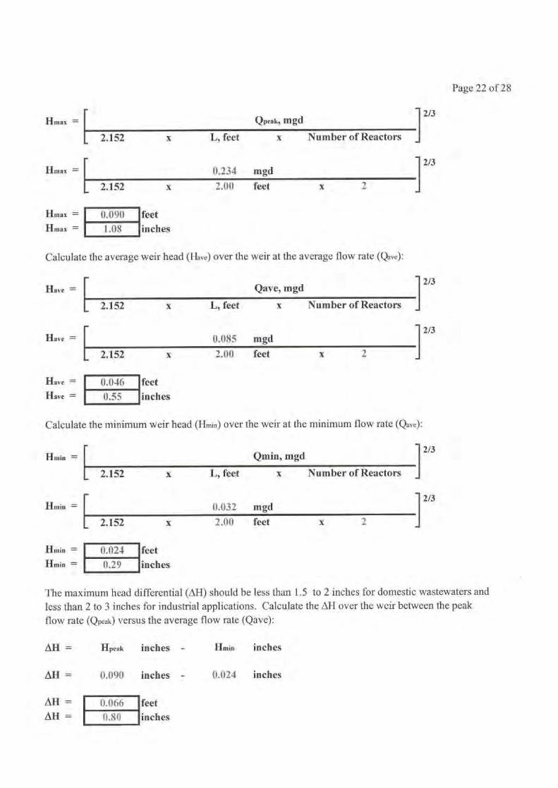
Page 22 of 28
Hmax =
Qpeak, mgd
2.152
x
L, feet
x
Number of Reactors
0.234 mgd
2.152
x
2.00
feet
x
2
Hmax
Hmax = I ().()90Hmax = I
1.08
feetinches
Calculate the average weir head (Have) over the weir at the average flow rate (Qave):
Qave, mgd
2.152
x
L, feet
x
Number of Reactors
0,085 mgd
2.152
x
2.00
feet
x
2
Have =
Have
0.0460.55
Have =
Have =
feetinches
Calculate the minimum weir head (Hmin) over the weir at the minimum flow rate (Qave):
Hmin =
Qmin, mgd
2.152
x
L, feet
x
Number of Reactors
0.032 mgd
2.152
x
2.00
feet
x
2
Hmin
Hmin =
Hmin =
0.024
0.29
feetinches
The maximum head differential (AH) should be less than 1.5 to 2 inches for domestic wastewaters andless than 2 to 3 inches for industrial applications. Calculate the 4H over the weir between the peak
flow rate (Qpeak) versus the average flow rate (Qave):
All =
Hpeak
inches
- Hmin inches
AH =
0.090
inches
- 0.024 inches
AH = 0.066 feetAH= 0,80 inches

Page 23 of 28
X. RETURN ACTIVATED SLUDGE AND SCUM AIRLIFT EQUIPMENT
Each E.A. Aerotor Plant typically is supplied with a return activated sludge air lift pump to return settledmixed liquor back to the aeration tank. A scum airlift pump if typically provided to return scum that hasbeen skimmed from the Spiraflo Clarifier race back to the aeration tank.
The maximum return activated sludge pumping rate (QRASmax) per E.A. Aerotor Plant is:
QRASmax =QRASmax =
0.063844
mgdgal/min
4
50
The return activated sludge air lift pump (inches) for the Model Number
15 is:
The maximum pumping capacity (gal/min) of this
4 inch air lift is:
Select whether the return activated sludge air lift is to be on the inside wall of the aeration channelor on the outside of the aeration channel:
Air lift is on the inside of the aeration channel:Air lift is on the outside of the aeration channel:
Air lift submergence, feet
The approximate required output blower capacity (scfin) for this application is:
The approximate required blower pressure (psig) for this application is:
The approximate required blower motor size (hp) for this application is:
X. ESTIMATED EQUIPMENT COSTS
E.A. AEROTOR PLANT MODEL
15
2
UNITS
1
12.00
30
4.0
2.0
Unit Price:
Total Price:Approximate Shipping Weight for each E.A. Aerotor Plant:
Approximate Installation Time for each E.A. Aerotor Plant:
5255,1111)
18,0004011
5510,200
lbhours
Page 24 of 28
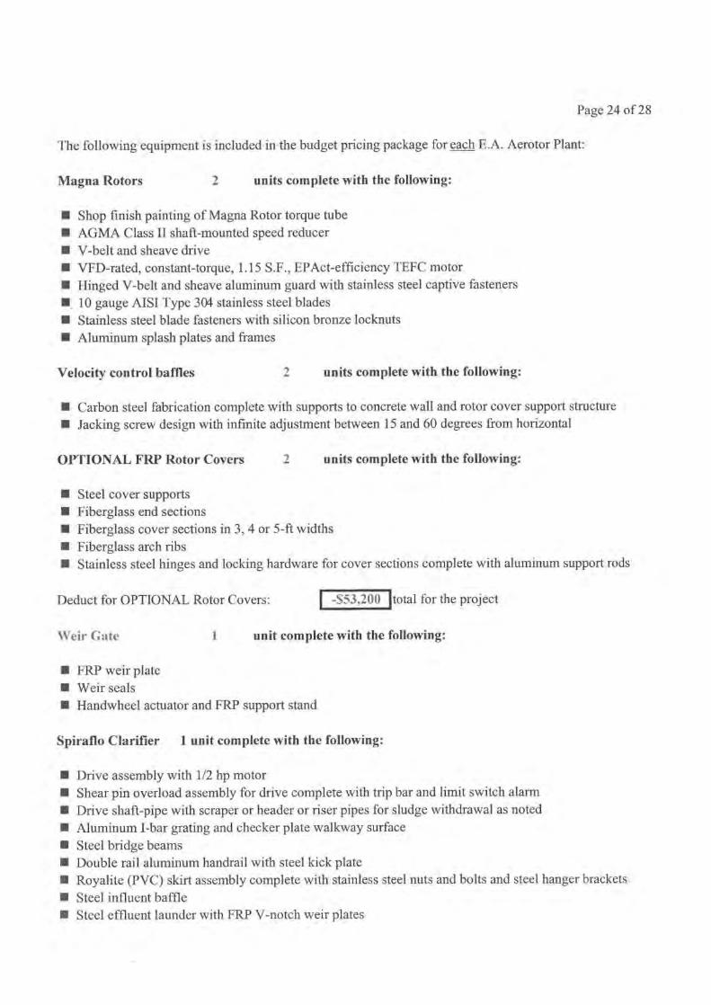
The following equipment is included in the budget pricing package for each E.A. Aerotor Plant:
Magna Rotors
2
units complete with the following:
n Shop finish painting of Magna Rotor torque tuben AGMA Class II shaft-mounted speed reducern V-belt and sheave driven VFD-rated, constant-torque, 1.15 S.F., EPAct-efficiency TEFC motorn Hinged V-belt and sheave aluminum guard with stainless steel captive fastenersn, 10 gauge AISI Type 304 stainless steel bladesn Stainless steel blade fasteners with silicon bronze locknutsn Aluminum splash plates and frames
Velocity control baffles
2
units complete with the following:
n Carbon steel fabrication complete with supports to concrete wall and rotor cover support structuren Jacking screw design with infinite adjustment between 15 and 60 degrees from horizontal
OPTIONAL FRP Rotor Covers
2
units complete with the following:
n Steel cover supportsn Fiberglass end sectionsn Fiberglass cover sections in 3, 4 or 5-ft widthsn Fiberglass arch ribsn Stainless steel hinges and locking hardware for cover sections complete with aluminum support rods
Deduct for OPTIONAL Rotor Covers: -S53,200
Weir Cate
1
unit complete with the following:
total for the project
n FRP weir platen Weir sealsn Handwheel actuator and FRP support stand
Spiraflo Clarifier
1 unit complete with the following:
n Drive assembly with 1/2 hp motorn Shear pin overload assembly for drive complete with trip bar and limit switch alarmn Drive shaft-pipe with scraper or header or riser pipes for sludge withdrawal as notedn Aluminum I-bar grating and checker plate walkway surfacen Steel bridge beamsn Double rail aluminum handrail with steel kick platen Royalite (PVC) skirt assembly complete with stainless steel nuts and bolts and steel hanger brackets
n Steel influent bafflen Steel effluent launder with FRP V-notch weir plates
Page 25 of 28
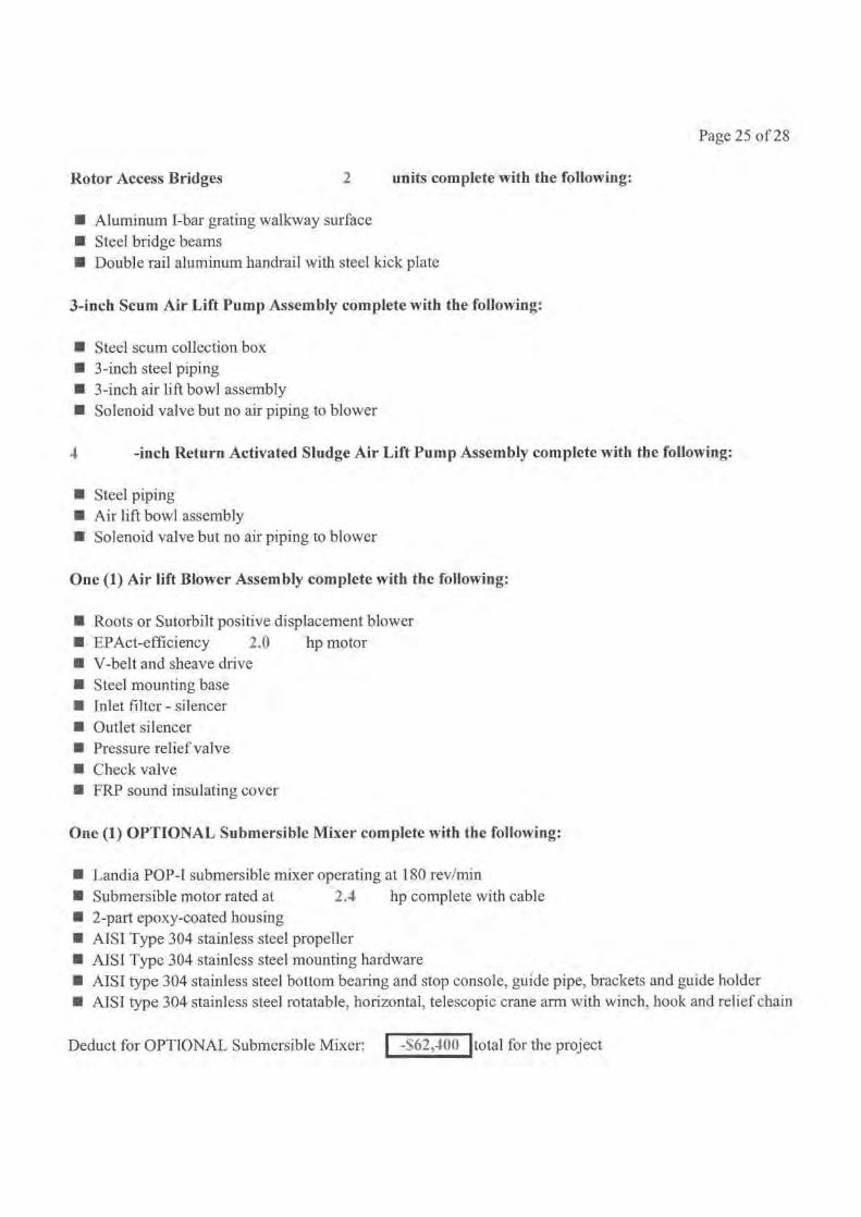
Rotor Access Bridges
2
units complete with the following:
n Aluminum I-bar grating walkway surfacen Steel bridge beamsn Double rail aluminum handrail with steel kick plate
3-inch Scum Air Lift Pump Assembly complete with the following:
n Steel scum collection boxn 3-inch steel pipingn 3-inch air lift bowl assemblyn Solenoid valve but no air piping to blower
4
-inch Return Activated Sludge Air Lift Pump Assembly complete with the following:
n Steel pipingn Air lift bowl assemblyn Solenoid valve but no air piping to blower
One (1) Air lift Blower Assembly complete with the following:
n Roots or Sutorbilt positive displacement blowern EPAct-efficiency 2.0 hp motorn V-belt and sheave driven Steel mounting basen Inlet filter - silencern Outlet silencern Pressure relief valven Check valven FRP sound insulating cover
One (1) OPTIONAL Submersible Mixer complete with the following:
n Landia POP-I submersible mixer operating at 180 rev/minn Submersible motor rated at 2.4 hp complete with cablen 2-part epoxy-coated housingn AISI Type 304 stainless steel propellern AISI Type 304 stainless steel mounting hardwaren AISI type 304 stainless steel bottom bearing and stop console, guide pipe, brackets and guide holdern AISI type 304 stainless steel rotatable, horizontal, telescopic crane arm with winch, hook and relief chain
Deduct for OPTIONAL Submersible Mixer:
-S62,400 total for the project
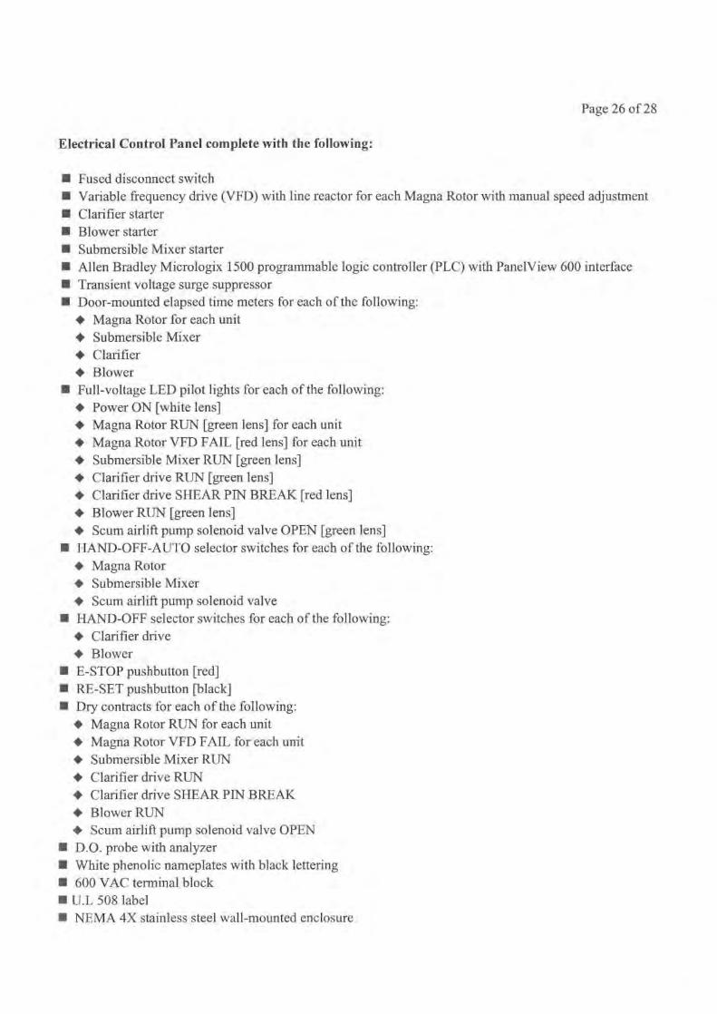
Page 26 of 28
Electrical Control Panel complete with the following:
n Fused disconnect switchn Variable frequency drive (VFD) with line reactor for each Magna Rotor with manual speed adjustmentn Clarifier startern Blower startern Submersible Mixer startern Allen Bradley Micrologix 1500 programmable logic controller (PLC) with PanelView 600 interfacen Transient voltage surge suppressorn Door-mounted elapsed time meters for each of the following:
♦ Magna Rotor for each unit♦ Submersible Mixer♦ Clarifier♦ Blower
n Full-voltage LED pilot lights for each of the following:♦ Power ON [white lens]♦ Magna Rotor RUN [green lens] for each unit♦ Magna Rotor VFD FAIL [red lens] for each unit♦ Submersible Mixer RUN [green lens]♦ Clarifier drive RUN [green lens]♦ Clarifier drive SHEAR PIN BREAK [red lens]♦ Blower RUN [green lens]♦ Scum airlift pump solenoid valve OPEN [green lens]
n HAND-OFF-AUTO selector switches for each of the following:♦ Magna Rotor♦ Submersible Mixer♦ Scum airlift pump solenoid valve
n HAND-OFF selector switches for each of the following:♦ Clarifier drive♦ Blower
n E-STOP pushbutton [red]n RE-SET pushbutton [black]n Dry contracts for each of the following:
♦ Magna Rotor RUN for each unit♦ Magna Rotor VFD FAIL for each unit♦ Submersible Mixer RUN♦ Clarifier drive RUN♦ Clarifier drive SHEAR PIN BREAK
Blower RUN• Scum airlift pump solenoid valve OPEN
n D.O. probe with analyzern White phenolic nameplates with black letteringn 600 VAC terminal blockn U.I. 508 labeln NEMA 4X stainless steel wall-mounted enclosure
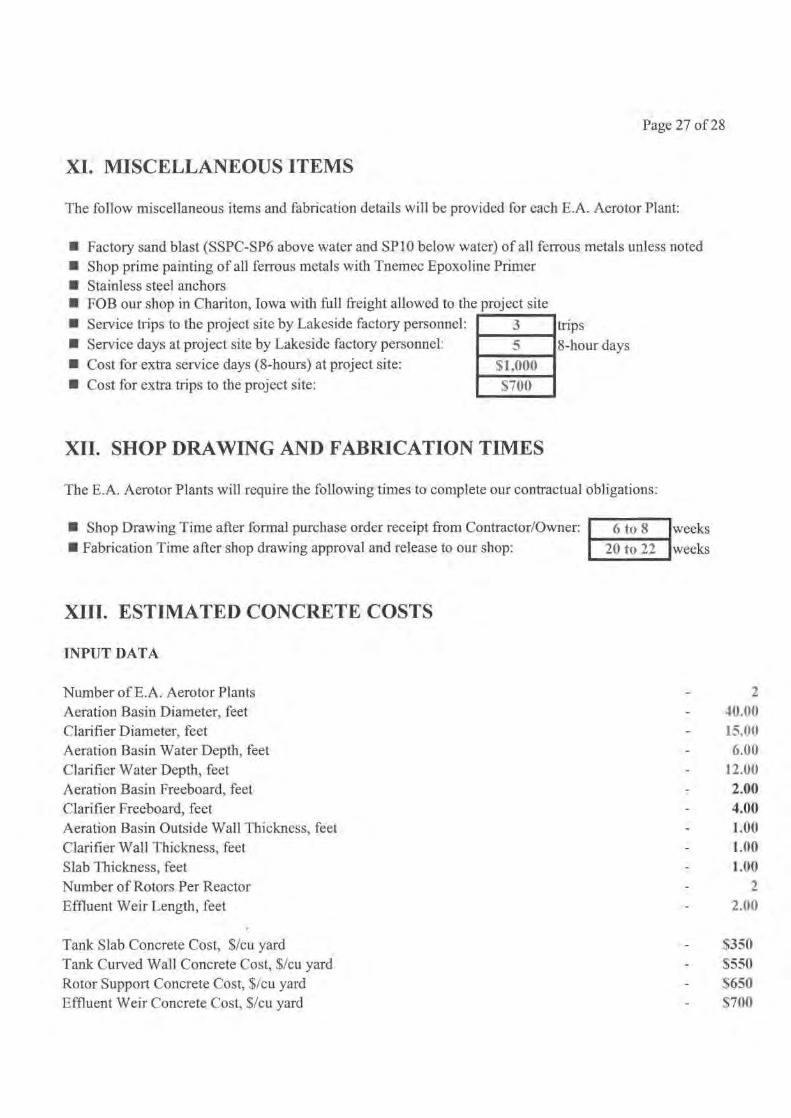
Page 27 of 28
XI. MISCELLANEOUS ITEMS
The follow miscellaneous items and fabrication details will be provided for each E.A. Aerotor Plant:
n Factory sand blast (SSPC-SP6 above water and SP10 below water) of all ferrous metals unless notedn Shop prime painting of all ferrous metals with Tnemec Epoxoline Primern Stainless steel anchorsn FOB our shop in Chariton, Iowa with full freight allowed to the project site
n Service trips to the project site by Lakeside factory personnel: 3 tripsn Service days at project site by Lakeside factory personnel: 5 8-hour daysn Cost for extra service days (8-hours) at project site:
n Cost for extra trips to the project site: S700
51 .000
XII. SHOP DRAWING AND FABRICATION TIMES
The E.A. Aerotor Plants will require the following times to complete our contractual obligations:
n Shop Drawing Time after formal purchase order receipt from Contractor/Owner:
n Fabrication Time after shop drawing approval and release to our shop:
XIII. ESTIMATED CONCRETE COSTS
INPUT DATA
Number of E.A. Aerotor Plants 2Aeration Basin Diameter, feet 40.00Clarifier Diameter, feet 15.00Aeration Basin Water Depth, feet 6.00Clarifier Water Depth, feet 12.00Aeration Basin Freeboard, feet 2.00Clarifier Freeboard, feet 4.00Aeration Basin Outside Wall Thickness, feet 1.00Clarifier Wall Thickness, feet 1.00Slab Thickness, feet 1.00Number of Rotors Per Reactor 2Effluent Weir Length, feet 2.00
Tank Slab Concrete Cost, $/cu yard S350Tank Curved Wall Concrete Cost, $/cu yard $550Rotor Support Concrete Cost, $/cu yard $650Effluent Weir Concrete Cost, $/cu yard $700
6 to 8 weeksweeks20 to 22
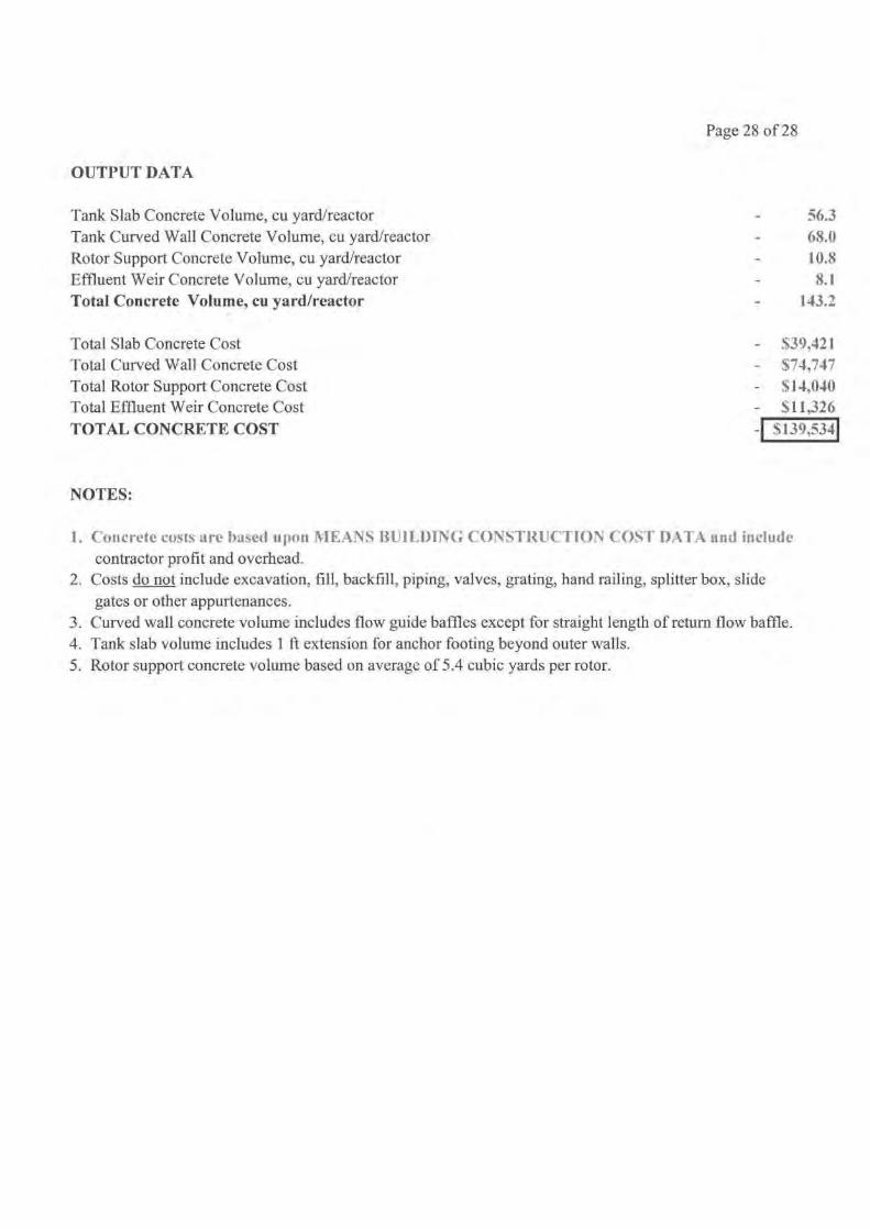
Page 28 of 28
OUTPUT DATA
Tank Slab Concrete Volume, cu yard/reactor 56.3Tank Curved Wall Concrete Volume, cu yard/reactor 68.0Rotor Support Concrete Volume, cu yard/reactor 10.8Effluent Weir Concrete Volume, cu yard/reactor 8.1Total Concrete Volume, cu yard/reactor 143.2
Total Slab Concrete Cost $39,421Total Curved Wall Concrete Cost '74,747Total Rotor Support Concrete Cost S14,040Total Effluent Weir Concrete Cost S11,326TOTAL CONCRETE COST I 5139,5341
NOTES:
1. Concrete costs are based upon MEANS BUILDING CONSTRUCTION COST DATA and includecontractor profit and overhead.
2. Costs do not include excavation, fill, backfill, piping, valves, grating, hand railing, splitter box, slidegates or other appurtenances.
3. Curved wall concrete volume includes flow guide baffles except for straight length of return flow baffle.4. Tank slab volume includes 1 ft extension for anchor footing beyond outer walls.5. Rotor support concrete volume based on average of 5.4 cubic yards per rotor.

Figure No. 1 E.A. Aerotor Process
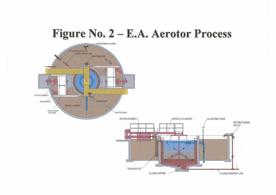
Figure No. 2 - E.A. Aerotor Process
ROTOR ASSEMBLY
SPIRAFLO CLARIFIER
ADJUSTABLE WEIR
SLUDGE HOPPER
SLUDGE DRAWOFF LINE

Figure No. 3 - Uncontrolled D.O.5.04.54.03.5
a'a 3.0
2.5°• 2.0
1.51.00.50.0 Time, hours
Reactor No. 1 D.O. - Reactor No. 2 D.O.
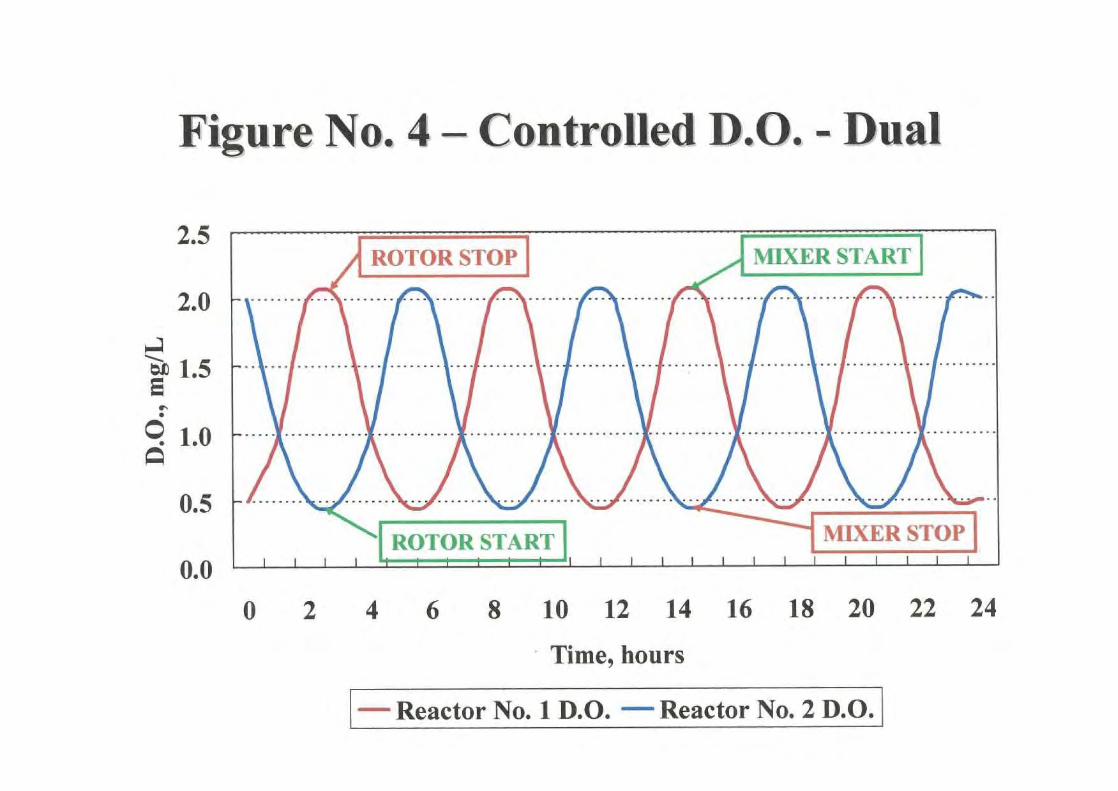
Figure No. 4 -Controlled D.O. - Dual
0
2
4
6
8 10 12 14 16 18 20 22 24
Time, hours
Reactor No. 1 D.O.
Reactor No. 2 D.O.
2.5
0.0
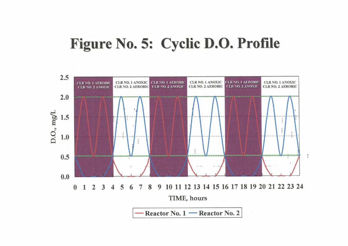
Figure No. 5: Cyclic D.O. Profile
2.5
2.0
0.5
0.0
CLR NO. 1 AEROBICCLR NO. 2 ANOXIC
CLR NO. 1 ANOXICCLR NO.2 AEROBIC
CLR NO..1 AEROBICCLRN0 2 ANOXIC
CLR NO. 1 ANOXICCLR NO.2 AEROBIC
CLR NO.:1 AEROBICCLR NO.2 ANOXIC
CLR NO. 1 ANOXICCLR NO.2 AEROBIC
0 1 2 3 4 5 6 7 8 9 10 11 12 13 14 15 16 17 18 19 20 21 22 23 24
TIME, hours
Reactor No. 1
Reactor No. 2

FIGURE NO. 6: Splitter Box Plan Designrr1r^{+^
^yy{y{WEIR PLATE - TYP.•: ^^ti•ti L: L' LS{,•.. ti.L•ti.ti L y5L.4 ti L:ti ti ti y .LS L: L^L•ti L:ti ti ti LSti ti ti y:ti L.yP^Lf
• {Yy{ti{•r•{ ,r J.} ,r J. .J`•.{'^^y{^1^1^y{y{: }L^y{•{ r•} }y{•{"{ } r. r'} }.}.r.r'
}'f^r^{. :}LJy }•}r: ~•i{ir.r.J. .r.J.r. .J.ry :r: Lr• y y y.1. y.y.{ L•L . y .1{^ti.L_
r• r• •r•r•r• J•r•r•r•
r^r^r
RAWWASTEWATER
RAS AIRLIFTPUMP FROMCLARIFIER
EAA-2 AMLSS TO
CLARIFIEREAA-2
AERATION LEVELCONTROL WEIR
TYP. OF 2 - BY LEC
SLIDE GATE - TYP.OF 5 - BY OTHERS
kger.r•r.r•r•r.r•r•r.r•r.r.r•r•r.r.r•r•r•r.r•r•J•r.r•J•J•r-r-r•r•r•ryr•r•
•r••L.L.L.L L L L•L•L•L•L.L.L L•L•'4.1•yL•L. L+L•L•y •. y.y.:.v::.:.-
yL L ti.L,r.r.r.r.r.}.},} r•r•J•r•r•r•}•J.r•r•r•r•r•r•r•J•J.} } J•r•r.J•r•r•r•r.r•} } r.r.L.y.y.L.L•L.''y-y-y.y.1.L.Yy.L.y-yyL.L.LfL.1,.L.ti.\.y.1„y.y.•.•L.y.y.5,.1.'^i.{•J•r.r•r.{•r.rY•J J•r.r•r.J•J•r.r•r.r.r J r.r.J•r•J.r.r.J.J r J.r J.r.r{yyy.}:}1risy :}:{:yri:y;ti :ti • }'yL.L:;:}:;?;}.^y :1^ :^:^ {:}.yy
RAS AIRLIFTPUMP FROMCLARIFIER
EAA-1
MLSS TOCLARIFIER
EAA-1
MLSS FROMEAA-2
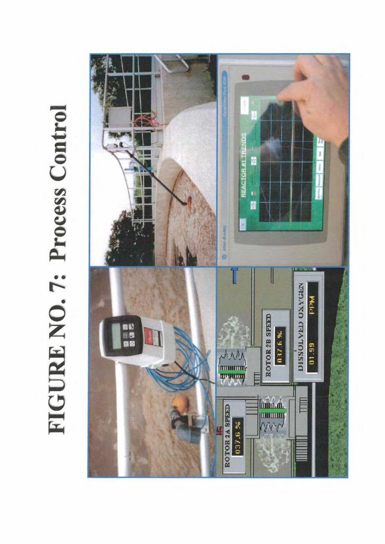
Bulletin #I93 August 2005
E.A. Aerotor Plant
-sp
x el
a
and Comp et \4ixing
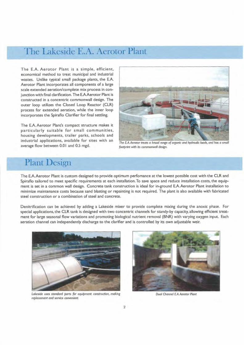
The Lakeside E.A. Aerotor Plant
The E.A. Aerotor Plant is a simple, efficient,economical method to treat municipal and industrialwastes. Unlike typical small package plants, the E.A.Aerotor Plant incorporates all components of a largescale extended aeration/complete mix process in con-junction with final clarification. The E.A.Aerotor Plant isconstructed in a concentric commonwall design. Theouter loop utilizes the Closed Loop Reactor (CLR)process for extended aeration, while the inner loopincorporates the Spiraflo Clarifier for final settling.
The E.A. Aerotor Plant's compact structure makes itparticularly suitable for small communities,housing developments, trailer parks, schools andindustrial applications, available for sites with anaverage flow between 0.01 and 0.5 mgd.
The E.A.Aerotor treats a broad range of organic and hydraulic loads, and has a small
footprint with its commonwall design.
Plant DesignThe E.A.Aerotor Plant is custom designed to provide optimum perfomance at the lowest possible cost with the CLR andSpiraflo tailored to meet specific requirements at each installation.To save space and reduce installation costs, the equip-ment is set in a common wall design. Concrete tank construction is ideal for in-ground E.A.Aerotor Plant installation tominimize maintenance costs because sand blasting or repainting is not required. The plant is also available with fabricatedsteel construction or a combination of steel and concrete.
Denitrification can be achieved by adding a Lakeside mixer to provide complete mixing during the anoxic phase. Forspecial applications, the CLR tank is designed with two concentric channels for standy-by capacity, allowing efficient treat-ment for large seasonal flow variations and promoting biological nutrient removal (BNR) with varying oxygen input. Eachaeration channel can independently discharge to the clarifier and is controlled by its own adjustable weir.
Lakeside uses standard parts for equipment construction, makingreplacement and service convenient
Dual Channel EA. Aerotor Plant
2
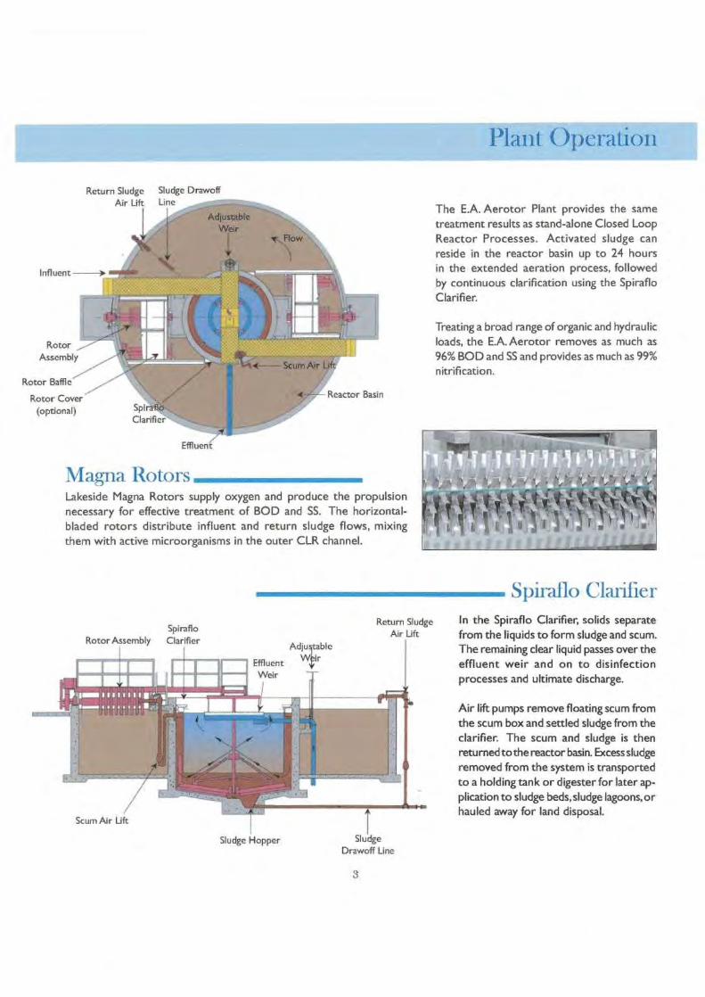
lant.Operat.ionIME=ILPThe E.A. Aerotor Plant provides the sametreatment results as stand-alone Closed LoopReactor Processes. Activated sludge canreside in the reactor basin up to 24 hoursin the extended aeration process, followedby continuous clarification using the SpirafloClarifier.
Treating a broad range of organic and hydraulicloads, the E.A. Aerotor removes as much as96% BOD and SS and provides as much as 99%nitrification.
Spiraflo ClarifierIn the Spiraflo Clarifier, solids separatefrom the liquids to form sludge and scum.The remaining clear liquid passes over theeffluent weir and on to disinfectionprocesses and ultimate discharge.
Air lift pumps remove floating scum fromthe scum box and settled sludge from theclarifier. The scum and sludge is thenreturned to the reactor basin. Excess sludgeremoved from the system is transportedto a holding tank or digester for later ap-plication to sludge beds,sludge lagoons, orhauled away for land disposal.
Effluent
Magna RotorsLakeside Magna Rotors supply oxygen and produce the propulsionnecessary for effective treatment of BOD and SS. The horizontal-bladed rotors distribute influent and return sludge flows, mixingthem with active microorganisms in the outer CLR channel.
Return SludgeAir Lift
Sludge Hopper SludgeDrawoff Line
3

ControlsThe E.A.Aerotor Plant reduces labor and maintenance costs withall operation and control equipment easily accessible from theaccess bridge. Controls for the Closed Loop Reactor andSpiraflo Clarifier are easy to use. Operators can control theamount of dissolved oxygen in the reactor basin by adjusting thereactor weir. The rate of return sludge to the reactor basin isadjusted by simply changing the air flow to the air lift pump.
Submersible MixersBy adding a Lakeside mixer to the CLR process, denitrifica-tion capabilities are enhanced while maintaining liquid velocity.Mixers can also reduce power costs in unusually low flowstart-up conditions where oxygen requirements are well belowmixing needs.
Treatment equipment and systems solutions from LakesideLakeside offers a wide range of equipment and systems for virtually all stages of wastewater treatment from influent throughfinal discharge. Each process and equipment item that we supply is manufactured with one goal in mind ... to reliablyimprove the quality of our water resources in the most cost-effective way possible.
We've been doing just that since 1928.
Aerationnewair® Diffuser
CLR ProcessE.A.Aerotor
Magna RotorsRotor Covers
Level Control Weirs
Submersible ProductsMixers
Propeller PumpsGrinder Pumps
ClarificationSpiraflo ClarifierSpiravac Clarifier
Tertiary Treatment using SeriesClarification
Full-Surface Skimming
Trickling Filters
Trash & Screen Rakes
RAPTOR' Screening ProductsFine Screen
Micro StrainerRotating Drum Screen
Wash PressSeptage Acceptance Plant
Other Screening ProductsWater Intake Screens
CSO Screens
Grit CollectionSpi raG rit
AeroductorRAPTOR® Grit WasherInline Grit Collector
Model L Grit Classifier
Screw PumpsOpen Screw Pumps
Enclosed Screw Pumps
Packaged Headworks SystemsRAPTOR®Complete Plant
H-PAC
1022 E. Devon, P.O. Box 8448Bartlett, IL 60103
630/837-5640, FAX: 630/837-5647E-mail: sales@lakeside-equipmentcom
http://www.lakeside-equipment.com
Bulletin 1414 July 2005
Magna Rotor Aerator
LAKESIDE112R
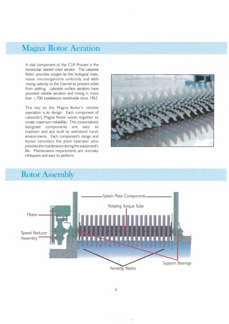
Magna Rotor Aeration
A vital component of the CLR Process is thehorizontal, bladed rotor aerator. The LakesideRotor provides oxygen to the biological mass,mixes microorganisms uniformly and addsmixing velocity to the channel to prevent solidsfrom settling. Lakeside surface aerators haveprovided reliable aeration and mixing in morethan 1,700 installations worldwide since 1962.
The key to the Magna Rotor's reliableoperation is its design. Each component ofLakeside's Magna Rotor works together tocreate maximum reliablility. The conservativelydesigned components are easy tomaintain and are built to withstand harshenvironments. Each component's design andlayout considers the plant operator whoprovides the maintenance during the equipment'slife. Maintenance requirements are normallyinfrequent and easy to perform.
Rotor Assembly
2
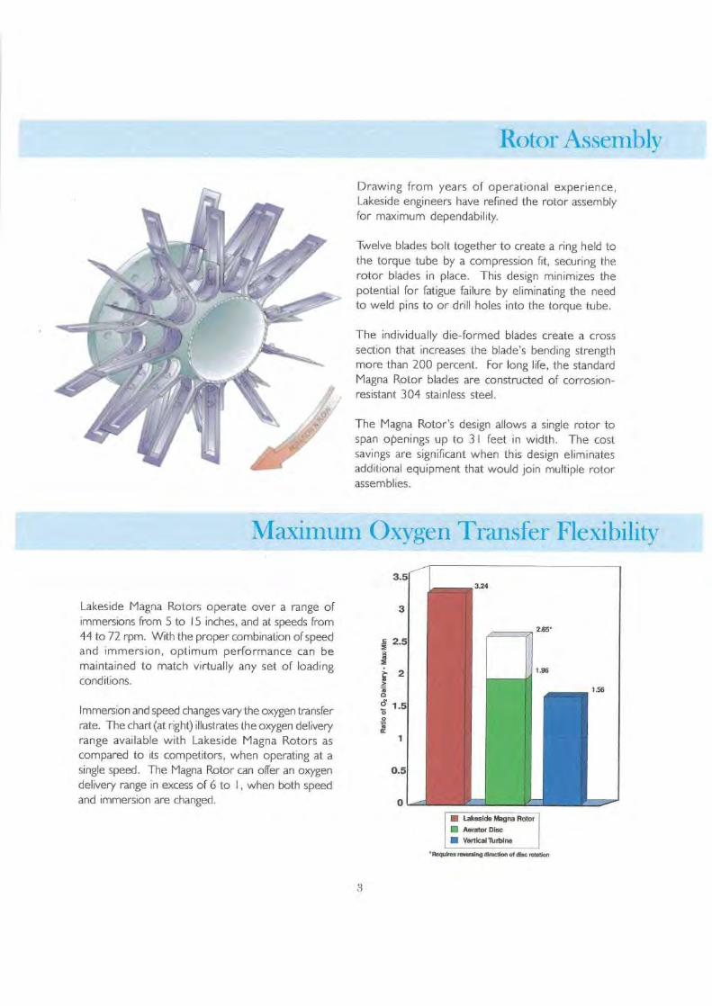
Rotor Assembly
Drawing from years of operational experience,Lakeside engineers have refined the rotor assemblyfor maximum dependability.
Twelve blades bolt together to create a ring held tothe torque tube by a compression fit, securing therotor blades in place. This design minimizes thepotential for fatigue failure by eliminating the needto weld pins to or drill holes into the torque tube.
The individually die-formed blades create a crosssection that increases the blade's bending strengthmore than 200 percent. For long life, the standardMagna Rotor blades are constructed of corrosion-resistant 304 stainless steel.
The Magna Rotor's design allows a single rotor tospan openings up to 31 feet in width. The costsavings are significant when this design eliminatesadditional equipment that would join multiple rotorassemblies.
Maximum Oxygen Transfer Flexibility
Lakeside Magna Rotors operate over a range ofimmersions from 5 to i 5 inches, and at speeds from44 to 72 rpm. With the proper combination of speedand immersion, optimum performance can bemaintained to match virtually any set of loadingconditions.
Immersion and speed changes vary the oxygen transferrate. The chart (at right) illustrates the oxygen deliveryrange available with Lakeside Magna Rotors ascompared to its competitors, when operating at asingle speed. The Magna Rotor can offer an oxygendelivery range in excess of 6 to 1, when both speedand immersion are changed.
n Lakeside Magna Rotor* Aerator Disc• Vertical Turbine
'Requires ravening rarecaon of dt c wanton
3
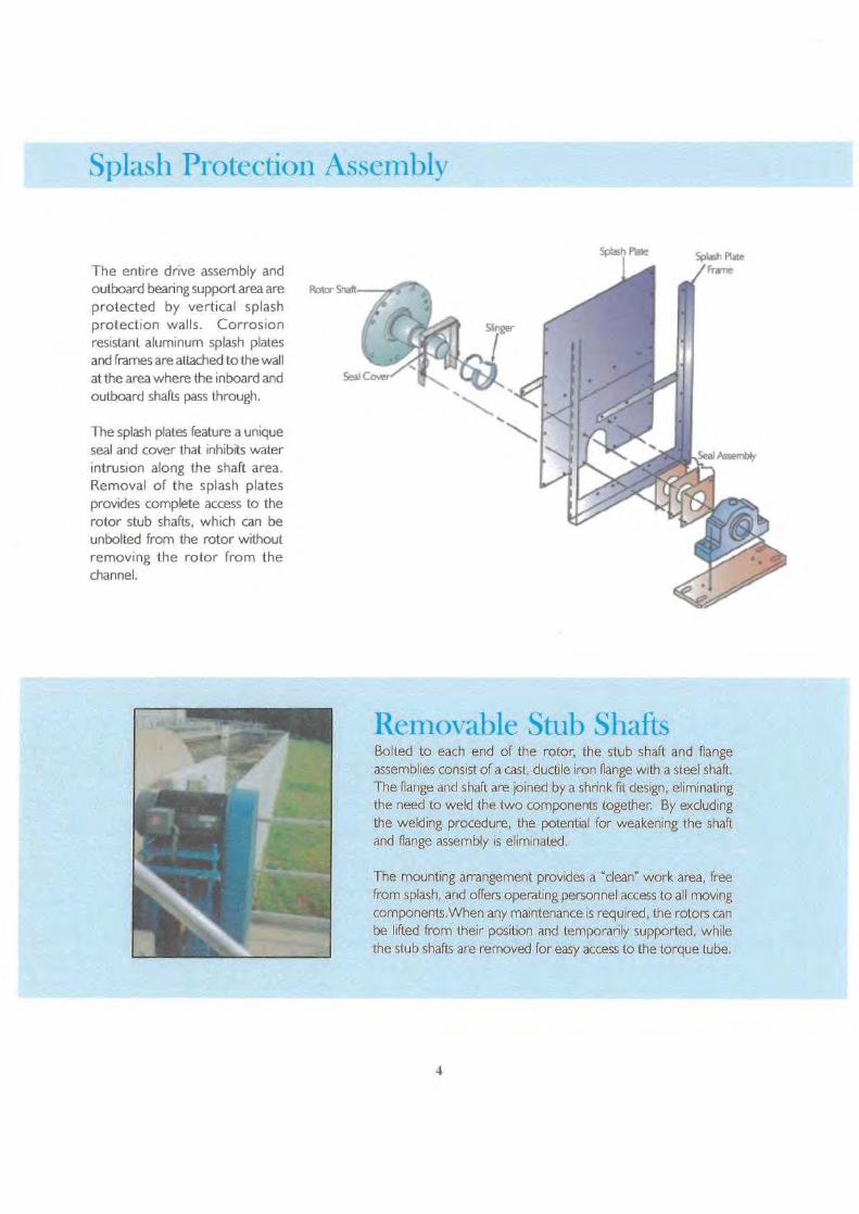
Splash Protection Assembly
The entire drive assembly andoutboard bearing support area are
Rotor snitprotected by vertical splashprotection walls. Corrosionresistant aluminum splash platesand frames are attached to the wallat the area where the inboard and
Seal Coe
outboard shafts pass through.
The splash plates feature a uniqueseal and cover that inhibits waterintrusion along the shaft area.Removal of the splash platesprovides complete access to therotor stub shafts, which can beunbolted from the rotor withoutremoving the rotor from thechannel.
Removable Stub ShaftsBolted to each end of the rotor, the stub shaft and flangeassemblies consist of a cast, ductile iron flange with a steel shaft.The flange and shaft are joined by a shrink fit design, eliminatingthe need to weld the two components together. By excludingthe welding procedure, the potential for weakening the shaftand flange assembly is eliminated.
The mounting arrangement provides a "clean" work area, freefrom splash, and offers operating personnel access to all movingcomponents.When any maintenance is required, the rotors canbe lifted from their position and temporarily supported, whilethe stub shafts are removed for easy access to the torque tube.
4
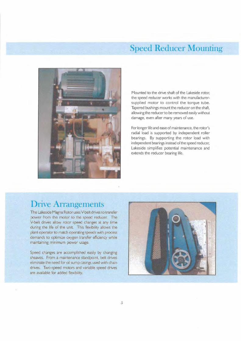
Speed Reducer Mounting
Mounted to the drive shaft of the Lakeside rotor,the speed reducer works with the manufacturer-suppfied motor to control the torque tube.Tapered bushings mount the reducer on the shaft,allowing the reducer to be removed easily withoutdamage, even after many years of use.
For longer life and ease of maintenance, the rotor'sradial load is supported by independent rollerbearings. By supporting the rotor load withindependent bearings instead of the speed reducer,Lakeside simplifies potential maintenance andextends the reducer bearing life.
Drive ArrangementsThe Lakeside Magna Rotor uses V-belt drives to transferpower from the motor to the speed reducer. TheV-belt drives allow rotor speed changes at any timeduring the life of the unit. This flexibility allows theplant operator to match operating speeds with processdemands to optimize oxygen transfer efficiency whilemaintaining minimum power usage.
Speed changes are accomplished easily by changingsheaves. From a maintenance standpoint, belt driveseliminate the need for oil sump casings used with chaindrives. Two-speed motors and variable speed drivesare available for added flexibility.
5

Rotor Support BearingsEach end of the rotor is independently supported by asplit, self-aligning roller bearing. The anti-friction bearingswith wet-duty seals are mounted in a spherical, machinedbearing cartridge. Self-alignment is provided by thecartridge, which fits precisely into the bearing housing.Misalignment does not disturb the seals because they arecompletely contained within the self-aligning bearingcartridge.
Bearings used for the Magna Rotor are constructed with standard
commercial items, making availablility convenient.
Dual locking collars help prevent rotor shaft wear bysecurely clamping the bearing 's inner race to the stub shaft,as well as deflect contaminants and liquids from the seals.If the bearing fails, the collars help ensure the inner racecontinues to rotate with the shaft. An expansion-stylebearing is used at one end of the rotor to accomodateexpansion/contraction due to temperature changes andpossible movement of the tank walls.
Bearing Housing
Bearing Cartridge
Wet Seal Duty
Collar
Bearing Cover
Tapered Roller Bearing
Inner Race
Stub Shaft
Rotor BafflesA velocity control baffle mounted downstream of each rotorin the closed loop reactor process controls excess liquid velocity
generated by the rotating blades.
The flow is directed downward in thebasin to create a rolling motion. Thisturbulent mixing ensures the uniformdistribution of oxygen in the tank'scontents at all depths.
By diverting the flow, the baffles reduceliquid velocity, thereby increasing theoxygen transfer efficiency.
6

Rotor Aerator Covers
An exterior surface gel coat provides ultrav[olet protection. The gelis also injected with a permanent light brown pigment.
Lakeside's Type E Rotor Aerator Covers provide more downstreamcoverage than any other cover on the market. Our covers extendover the rotor baffles to trap and contain vtrtuaily 100% of the mistand spray. Ultimately, the covers minimize messy sludge on wallsand walkways, and improve the appearance of the plant.
A combination of 3-, 4- and 5-foot panels can cover various lengthsof rotor aerators. The rotor cover panels are attached to a fabricatedsteel support structure securely anchored to the sides of the aerationchamber. The unique spirt hinged design - a hinged front sectionconnected to a fixed rear section - allows individual panels to openwithout removing or opening adjacent panels. Each panel has ahard, tight grain and smooth outer surface that is easy to clean.The non-corrosive panels are assembled with stainless steel fastenersfor an extended life with minimal maintenance.
The panels are constructed with molded, non-corrosive fiberglassthat is sturdy, but lightweight; the maximum force needed to raiseany panel is less than 60 lbs. Arch supports between each panelseal the assembly and prevent leaks. Each arch support is designedwith a channel that collects liquid and allows it to drain back intothe water stream. For more support, each panel has choppedstrands of fiberglass in its interior rib area. Additional fiberglass matreinforces all bolt holes for structural support.
I 2keside Rotor Cover Advantages• Maintain 02 transfer effiency of rotors and
mixed liquor velocity
• Custom designs for each application
• Extend over rotor baffles• Hinged for easy access to rotors• Sturdy, lightweight, non-corrosive fiberglass
construction
• Minimizes sludge on walls and walkways+ Improves appearance of plant• Protects against heat loss

Rotor Cover Design Considerations
Lakeside Rotor Covers contain the mist and spray producedby the rotor aerator but do not restrict its flow pattern.The Type E covers provide significantly more coverage thanany of the competition, an important fact when baffles arepart of the design. Many cover designs have hatches orsmall ports for access to the rotors. These small accesspoints make it difficult and time consuming to work on therotors. The Type E cover, with hinged front panels, providesopen access to the complete rotor for any inspection orwork.
ecc co,ratEFmxASsEACH PNb
FLOW
Treatment equipment and systems solutions from LakesideLakeside offers a wide range of equipment and systems for virtually all stages of wastewater treatment from influent through finaldischarge. Each process and equipment item that we supply is manufactured with one goal in mind . . . to reliablyimprove the quality of our water resources in the most cost-effective way possible.
We've been doing just that since 1928.
Aerationnewai r® Diffuser
CLFZ ProcessE.A. Aerator
Magna RotorsRotor Covers
Level Control Weirs
Submersible ProductsMixers
Propeller PumpsGrinder Pumps
ClarificationSpiratio CiarifierSpiravac Clarifier
Tertiary Treatment using SeriesClarification
Full Surface Skimming
Trickling Filters
Trash & Screen Rakes
RAPTOR' Screening ProductsFine Screen
Micro StrainerRotating Drum Screen
Wash PressSeptage Acceptance Plant
Other Screening ProductsWater Intake Screens
CSO Screens
Grit CollectionSpiraGrit
AeroductorRAPTOR' Grit Washer
Inline Grit CollectorModel L Grit Classifier
Screw PumpsOpen Screw Pumps
Endosed Screw Pumps
LAKESIDEpL .:ux:^^ S
1 28
1022 E. Devon, P.O. Box 5448Bartlett, IL 60103
680/837-3640, FAX: 680/837-5637E-mail: [email protected]
Packaged Headworks SystemsRAPTOR®Complete Plant
H-PAC
Computerized Process`"- onfor
Complete Plant Management
• Energy Savings
• Kinetic Modeling• Process Optimization• Real-Time Monitoring
▪ Remote Alarm M4onitoring• State Monitoring Report Package• System Integration
• User-Friendly/Flexible
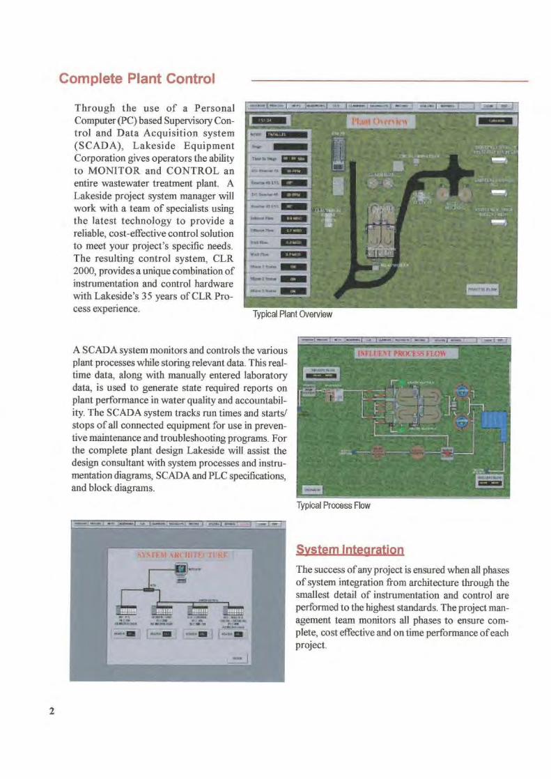
Complete Plant Control
Typical Plant Overview
Through the use of a PersonalComputer (PC) based Supervisory Con-trol and Data Acquisition system(SCADA), Lakeside EquipmentCorporation gives operators the abilityto MONITOR and CONTROL anentire wastewater treatment plant. ALakeside project system manager willwork with a team of specialists usingthe latest technology to provide areliable, cost-effective control solutionto meet your project's specific needs.The resulting control system, CLR2000, provides a unique combination ofinstrumentation and control hardwarewith Lakeside's 35 years of CLR Pro-cess experience.
A SCADA system monitors and controls the variousplant processes while storing relevant data. This real-time data, along with manually entered laboratorydata, is used to generate state required reports onplant performance in water quality and accountabil-ity. The SCADA system tracks run times and starts/stops of all connected equipment for use in preven-tive maintenance and troubleshooting programs. Forthe complete plant design Lakeside will assist thedesign consultant with system processes and instru-mentation diagrams, SCADA and PLC specifications,and block diagrams.
Typical Process Flow
System Integration
The success of any project is ensured when all phasesof system integration from architecture through thesmallest detail of instrumentation and control areperformed to the highest standards. The project man-agement team monitors all phases to ensure com-plete, cost effective and on time performance of eachproject.
fi yr crstf`is'zii1'1.0
i
oF'l.{) t,
2
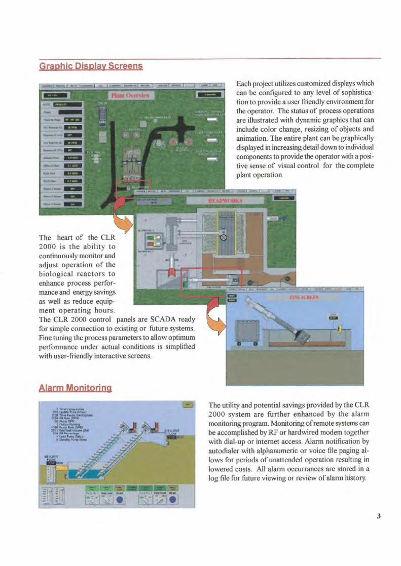
Graphic Display Screens,
Each project utilizes customized displays whichcan be configured to any level of sophistica-tion to provide a user friendly environment forthe operator. The status of process operationsare illustrated with dynamic graphics that caninclude color change, resizing of objects andanimation. The entire plant can be graphicallydisplayed in increasing detail down to individualcomponents to provide the operator with a posi-tive sense of visual control for the completeplant operation.
The heart of the CLR2000 is the ability tocontinuously monitor andadjust operation of thebiological reactors toenhance process perfor-mance and energy savingsas well as reduce equip-ment operating hours.The CLR 2000 control panels are SCADA readyfor simple connection to existing or future systems.Fine tuning the process parameters to allow optimumperformance under actual conditions is simplifiedwith user-friendly interactive screens.
The utility and potential savings provided by the CLR2000 system are further enhanced by the alarmmonitoring program. Monitoring of remote systems canbe accomplished by RF or hardwired modem togetherwith dial-up or internet access. Alarm notification byautodialer with alphanumeric or voice file paging al-lows for periods of unattended operation resulting inlowered costs. All alarm occurrances are stored in alog file for future viewing or review of alarm history.
3
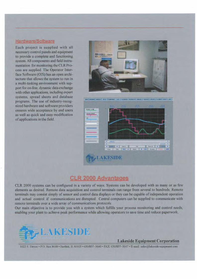
Hardware/SoftwareEach project is supplied with allnecessary control panels and equipmentto provide a complete and functioningsystem. All components and field instru-mentation for monitoring the CLR Pro-cess are supplied. The Operator Inter-face Software (OIS) has an open archi-tecture that allows the system to run ina multi-tasking environment with sup-port for on-line, dynamic data exchangewith other applications, including expertsystems, spread sheets and databaseprograms. The use of industry-recog-nized hardware and software providersensures wide acceptance by end usersas well as quick and easy modificationof applications in the field.
g'^..4 .wj6.
j rwwrr.) .»... 1 I ..^. I-- i ..^ ^.^:
,w.
iw..•
;f.
ii i
,
r..^ i
•M
AKESIDE
LR 2000 AdvantagesCLR 2000 systems can be configured in a variety of ways. Systems can be developed with as many or as fewelements as desired. Remote data acquisition and control terminals can range from several to hundreds. Remoteterminals may consist simply of sensor and control data displays or they can be capable of independent operationand actual control if communications are disrupted. Central computers can be supplied to communicate withremote terminals over a wide array of communications protocols.Our main objective is to provide you with a system which fulfills your process monitoring and control needs,enabling your plant to achieve peak performance while allowing operators to save time and reduce paperwork.
gi
SI1)I..:: ..
Lakeside Equipment Corporation1022 E. Devon •P O. Box 8448 • Bartlett IL 60103 • 630/837-5640 • FAX: 630/837-5617 • E-mail: salesIa)lakeside-equipment.eom
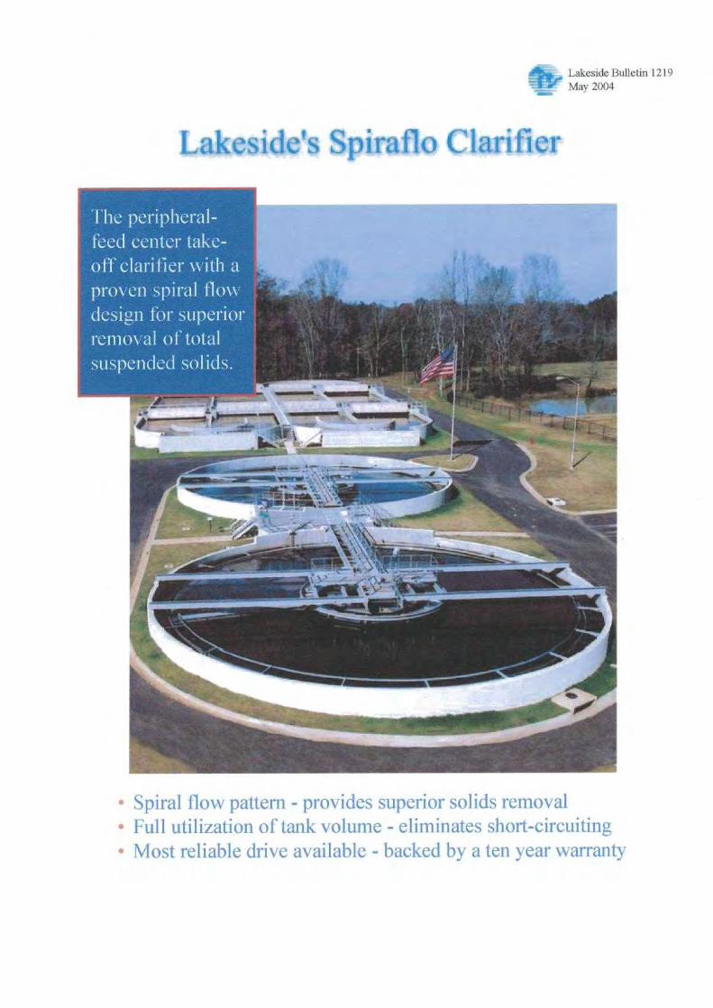
Lakeside Bulletin 1219May 2004
Lakeside's Spiraflo Clarifier
• Spiral flow pattern - provides superior solids removal• Full utilization of tank volume - eliminates short-circuiting• Most reliable drive available - backed by a ten year warranty
The peripheral-feed center take-off clarifier with aproven spiral flowdesign for superiorremoval of totalsuspended solids.
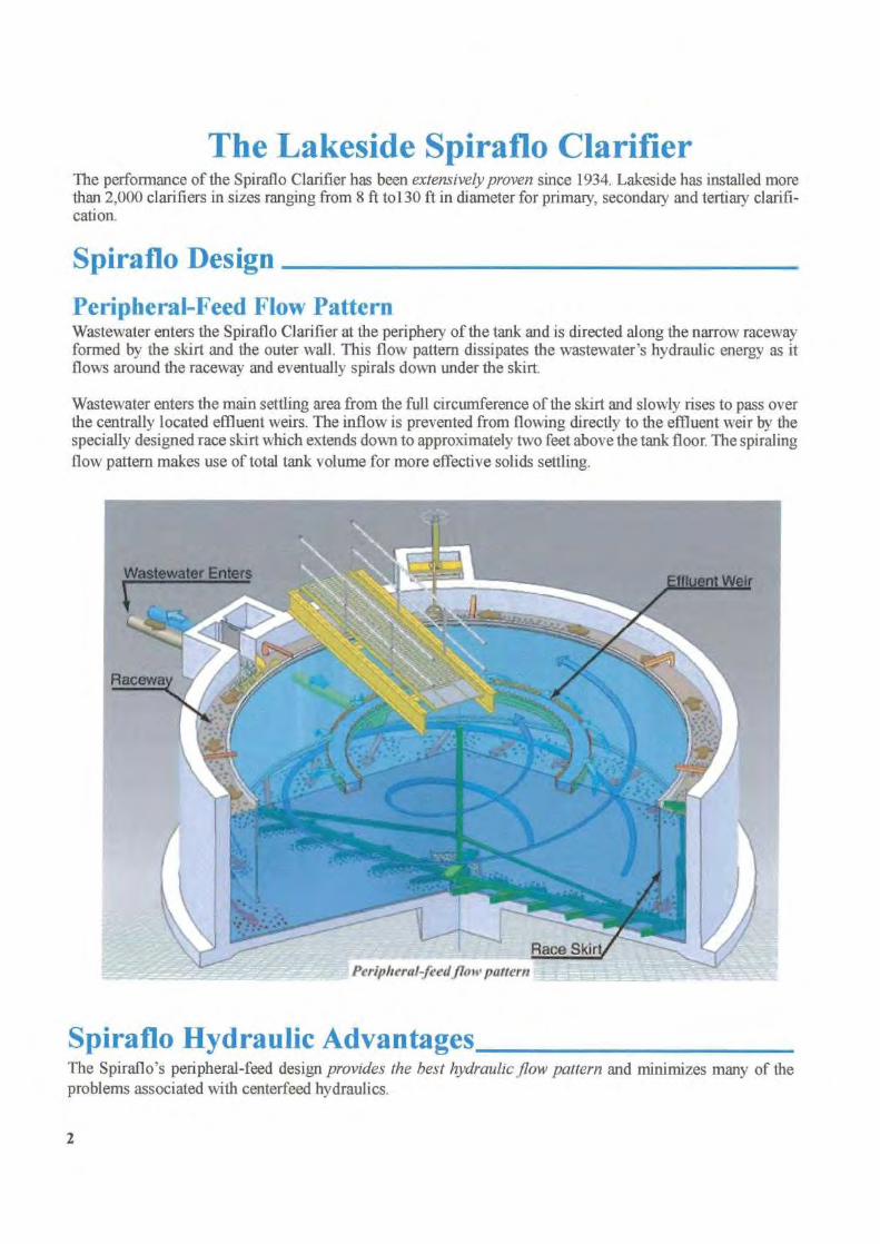
The Lakeside Spiraflo ClarifierThe performance of the Spiraflo Clarifier has been extensively proven since 1934. Lakeside has installed morethan 2,000 clarifiers in sizes ranging from 8 ft to130 ft in diameter for primary, secondary and tertiary clarifi-cation.
Spiraflo Design
Peripheral-Feed Flow PatternWastewater enters the Spiraflo Clarifier at the periphery of the tank and is directed along the narrow racewayformed by the skirt and the outer wall. This flow pattern dissipates the wastewater's hydraulic energy as itflows around the raceway and eventually spirals down under the skirt.
Wastewater enters the main settling area from the full circumference of the skirt and slowly rises to pass overthe centrally located effluent weirs. The inflow is prevented from flowing directly to the effluent weir by thespecially designed race skirt which extends down to approximately two feet above the tank floor. The spiralingflow pattern makes use of total tank volume for more effective solids settling.
Spiraflo Hydraulic AdvantagesThe Spiraflo's peripheral-feed design provides the best hydraulic flow pattern and minimizes many of theproblems associated with centerfeed hydraulics.
2
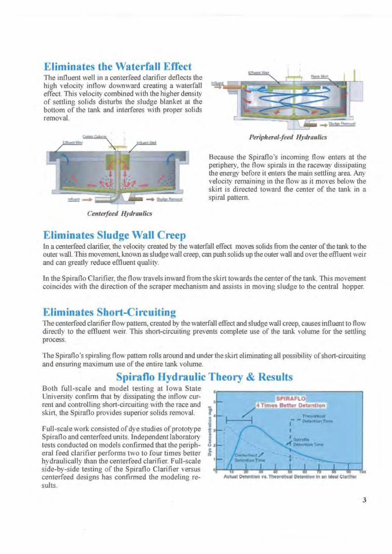
Eliminates the Waterfall EffectThe influent well in a centerfeed clarifier deflects thehigh velocity inflow downward creating a waterfalleffect. This velocity combined with the higher densityof settling solids disturbs the sludge blanket at thebottom of the tank and interferes with proper solidsremoval.
Centerfeed Hydraulics
Because the Spiraflo"s incoming flow enters at theperiphery, the flow spirals in the raceway dissipatingthe energy before it enters the main settling area. Anyvelocity remaining in the flow as it moves below theskirt is directed toward the center of the tank in aspiral pattern.
Eliminates Sludge Wall CreepIn a centerfeed clarifier, the velocity created by the waterfall effect moves solids from the center of the tank to theouter wall. This movement, known as sludge wall creep, can push solids up the outer wall and over the effluent weirand can greatly reduce effluent quality.
In the Spiraflo Clarifier, the flow travels inward from the skirt towards the center of the tank. This movementcoincides with the direction of the scraper mechanism and assists in moving sludge to the central hopper.
Eliminates Short-CircuitingThe centerfeed clarifier flow pattern, created by the waterfall effect and sludge wall creep, causes influent to flowdirectly to the effluent weir. This short-circuiting prevents complete use of the tank volume for the settlingprocess.
The Spiraflo's spiraling flow pattern rolls around and under the skirt eliminating all possibility of short-circuitingand ensuring maximum use of the entire tank volume.
Spiraflo Hydraulic Theory & ResultsBoth full-scale and model testing at Iowa StateUniversity confirm that by dissipating the inflow cur-rent and controlling short-circuiting with the race andskirt, the Spiraflo provides superior solids removal.
1Full-scale work consisted of dye studies of prototypeSpiraflo and centerfeed units. Independent laboratorytests conducted on models confirmed that the periph-eral feed clarifier performs two to four times betterhydraulically than the centerfeed clarifier. Full-scaleside-by-side testing of the Spiraflo Clarifier versuscenterfeed designs has confirmed the modeling re-sults.
AclwI Detention re. Theetetlcei DeW nM' n m an ideal Clwift
3

Sludge RemovalConventional Scrapers
Spiral ScrapersAngled scrapers push the settled solids or sludge tothe centrally located hopper for removal. The hydrau-lic flow in the main settling area moves in the samedirection as the angled scrapers and actually helps movethe sludge gently toward the center of the tank.
Conventional straight-blade angled scrapers.
Continuously tapered spiral-shaped scraper blades andfaster operating tip speeds enable the plant operatorto increase sludge transport capacity and improve re-turn sludge concentrations.
Spiral-bladed scraper.
Spiravac Clarifier - Rapid Suction RemovalThe Spiravac Clarifier uses rotating "V"-plows to direct settled solids to suction nozzles for sludge removal. Heavy,gritty material too large to be withdrawn passes through the "V" apex. Succeeding plows push this heavy material tothe sludge sump located at the clarifier center for removal from the tank. The spiral flow pattern also helps direct thesludge to the central draw-off point. The Spiravac offers either controlled or direct removal of activated sludge.
Individual sludge removal pipes .for Type CR design.
Controlled Removal (Type CR)The Type CR Spiravac allows the operator to vary the qual-ity and quantity of flow from each sludge removal pipe.The smooth plastic sludge removal pipes and rotating valveconstruction help eliminate plugging problems and thehang-up of stringy material at the valve discharge. The con-trolled removal design allows removal of obstructions inthe sludge piping without dewatering the tank.
Common header pipe removes sludge in TypeDR design.
Direct Removal (Type DR)The Type DR Spiravac collects activated sludge fromsuction nozzles on a common header tube rotating onthe clarifier floor. The sludge is suctioned off the floorand removed from the tank through a rotating mani-fold at the tank center.
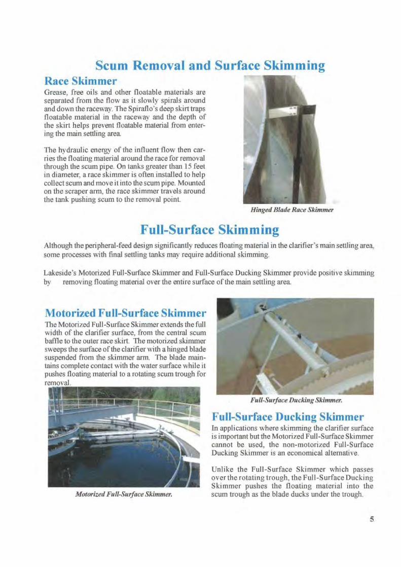
Scum Removal and Surface SkimmingRace SkimmerGrease, free oils and other floatable materials areseparated from the flow as it slowly spirals aroundand down the raceway. The Spiraflo's deep skirt trapsfloatable material in the raceway and the depth ofthe skirt helps prevent floatable material from enter-ing the main settling area.
The hydraulic energy of the influent flow then car-ries the floating material around the race for removalthrough the scum pipe. On tanks greater than 15 feetin diameter. a race skimmer is often installed to helpcollect scum and move it into the scum pipe. Mountedon the scraper arm, the race skimmer travels aroundthe tank pushing scum to the removal point.
Hinged Blade Race Skimmer
Full-Surface SkimmingAlthough the peripheral-feed design significantly reduces floating material in the clarifier's main settling area,some processes with final settling tanks may require additional skimming.
Lakeside's Motorized Full-Surface Skimmer and Full-Surface Ducking Skimmer provide positive skimmingby
removing floating material over the entire surface of the main settling area.
Motorized Full-Surface SkimmerThe Motorized Full-Surface Skimmer extends the fullwidth of the clarifier surface, from the central scumbaffle to the outer race skirt. The motorized skimmersweeps the surface of the clarifier with a hinged bladesuspended from the skimmer arm. The blade main-tains complete contact with the water surface while itpushes floating material to a rotating scum trough forremoval .
Motorized Full-Surface Skimmer.
Full-Surface Ducking SkimmerIn applications where skimming the clarifier surfaceis important but the Motorized Full-Surface Skimmercannot be used, the non-motorized Full-SurfaceDucking Skimmer is an economical alternative.
Unlike the Full-Surface Skimmer which passesover the rotating trough, the Full-Surface DuckingSkimmer pushes the floating material into thescum trough as the blade ducks under the trough.
5
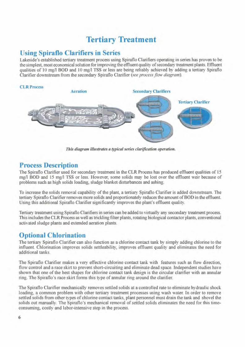
Tertiary Treatment
Using Spiraflo Clarifiers in SeriesLakeside's established tertiary treatment process using Spiraflo Clarifiers operating in series has proven to bethe simplest, most economical solution for improving the effluent quality of secondary treatment plants. Effluentqualities of 10 mg/1 BOD and 10 mg/1 TSS or less are being reliably achieved by adding a tertiary SpirafloClarifier downstream from the secondary Spiraflo Clarifier (see process flaw diagram).
CLR ProcessAeration
Secondary Clarifiers
This diagram illustrates a typical series clarification operation.
Process DescriptionThe Spiraflo Clarifier used for secondary treatment in the CLR Process has produced effluent qualities of 15mg/l BOD and 15 mg/l TSS or less. However, some solids may be lost over the effluent weir because ofproblems such as high solids loading, sludge blanket disturbances and ashing.
To increase the solids removal capability of the plant, a tertiary Spiraflo Clarifier is added downstream. Thetertiary Spiraflo Clarifier removes more solids and proportionately reduces the amount of BOD in the effluent.Using this additional Spiraflo Clarifier significantly improves the plant's effluent quality.
Tertiary treatment using Spiraflo Clarifiers in series can be added to virtually any secondary treatment process.This includes the CLR Process as well as trickling filter plants, rotating biological contactor plants, conventionalactivated sludge plants and extended aeration plants.
Optional ChlorinationThe tertiary Spiraflo Clarifier can also function as a chlorine contact tank by simply adding chlorine to theinfluent. Chlorination improves solids settleability, improves effluent quality and eliminates the need foradditional tanks.
The Spiraflo Clarifier makes a very effective chlorine contact tank with features such as flow direction,flow control and a race skirt to prevent short-circuiting and eliminate dead space. Independent studies haveshown that one of the best shapes for chlorine contact tank design is the circular clarifier with an annularring. The Spiraflo's race skirt forms this type of annular ring around the clarifier.
The Spiraflo Clarifier mechanically removes settled solids at a controlled rate to eliminate hydraulic shockloading, a common problem with other tertiary treatment processes using wash water. In order to removesettled solids from other types of chlorine contact tanks, plant personnel must drain the tank and shovel thesolids out manually. The Spiraflo's mechanical removal of settled solids eliminates the need for this time-consuming, costly and labor-intensive step in the process.
6
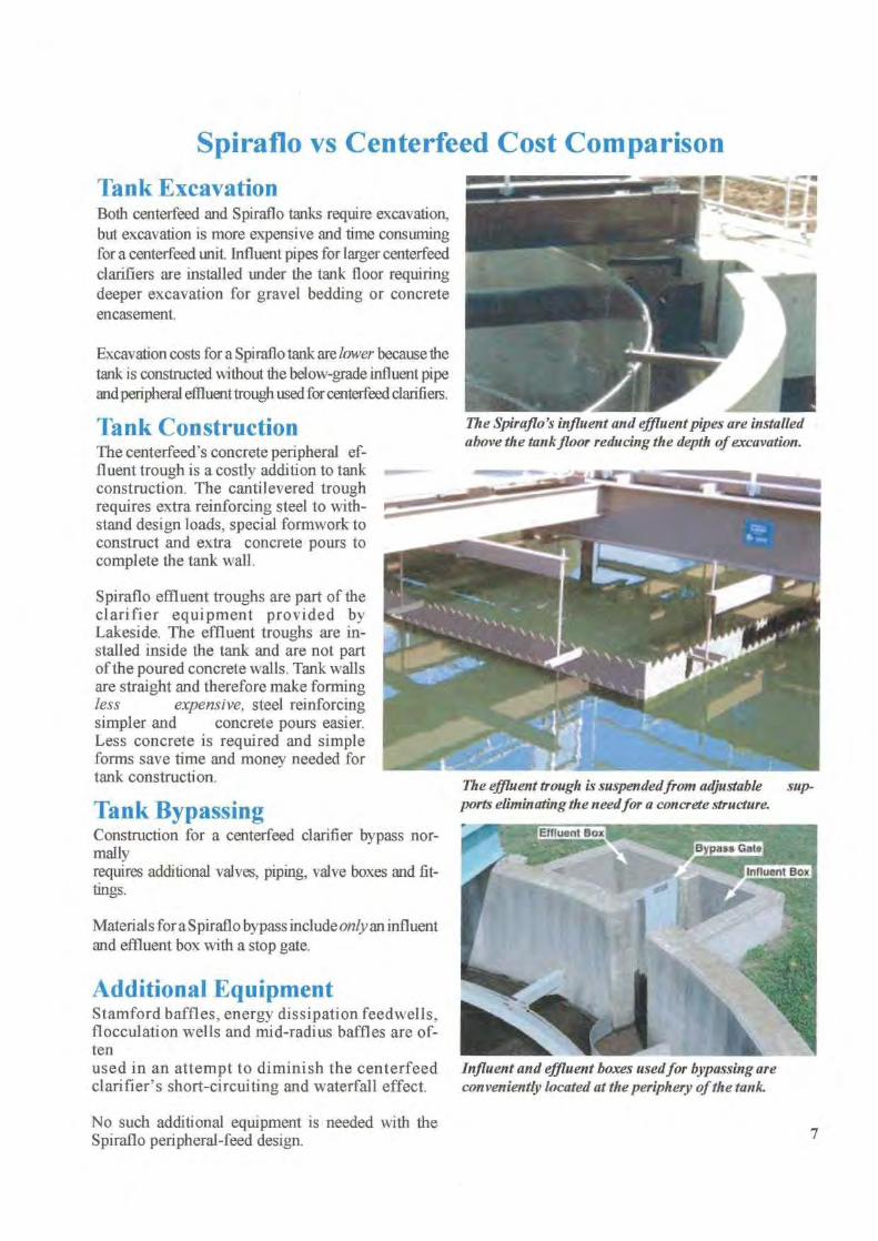
Spiraflo vs Centerfeed Cost Comparison
Tank ExcavationBoth centerfeed and Spiraflo tanks require excavation,but excavation is more expensive and time consumingfor a centerfeed unit. Influent pipes for larger centerfeedclarifiers are installed under the tank floor requiringdeeper excavation for gravel bedding or concreteencasement.
Excavation costs for a Spiraflo tank are lower because thetank is constructed without the below-grade influent pipeand peripheral effluent trough used for centerfeed clarifiers.
Tank ConstructionThe centerfeed's concrete peripheral ef-fluent trough is a costly addition to tankconstruction. The cantilevered troughrequires extra reinforcing steel to with-stand design loads, special formwork toconstruct and extra concrete pours tocomplete the tank wall.
Spiraflo effluent troughs are part of theclarifier equipment provided byLakeside. The effluent troughs are in-stalled inside the tank and are not partof the poured concrete walls. Tank wallsare straight and therefore make formingless
expensive, steel reinforcingsimpler and concrete pours easier.Less concrete is required and simpleforms save time and money needed fortank construction.
Tank BypassingConstruction for a centerfeed clarifier bypass nor-mallyrequires additional valves, piping, valve boxes and fit-tings.
Materials for a Spiraflo bypass include only an influentand effluent box with a stop gate.
Additional EquipmentStamford baffles, energy dissipation feedwells,flocculation wells and mid-radius baffles are of-tenused in an attempt to diminish the centerfeedclarifier's short-circuiting and waterfall effect.
No such additional equipment is needed with theSpiraflo peripheral-feed design.
The Spiraflo's influent and effluent pipes are installedabove the tank floor reducing the depth of excavation.
The effluent trough is suspended from adjustable sup-ports eliminating the needfor a concrete structure.
Influent and effluent boxes usedfor bypassing areconveniently located at the periphery of the tank
7

Spiraflo ApplicationsSpiraflo Clarifiers can be used in water, wastewater and industrial applications to remove all types of settleablesolids. The Spiraflo's proven spiral flow design provides superior removal for even the toughest applications.
Spiraflo BenefitsThe peripheral-feed design incorporates advantagesthat provide unequalled performance.
More than 2000 installations have proven that theLakeside Spiraflo Clarifiers:
• produce the highest quality effluent• improve sludge collection and removal• promote full utilization of tank volume• eliminate short-circuiting• handle peak flows effectively• retain suspended solids in the sludge blanket• eliminate sludge wall creep that is created by the
waterfall effect
Ten Year Clarifier Drive WarrantyWhen you specify a Lakeside Spiraflo or SpiravacClarifier you'll not only get the superior performanceof a peripheral-feed clarifier, you ' ll also get the mostreliable drive available. Our dedication to quality andproven reliability allows Lakeside to stand behind ourclarifier drive with a 10 year warranty.
LAKESIDE1022 E. Devon, PO_ Box 8448Bartlett, IL 60103630/837-5640, FAX 6301837-5647E-mail: [email protected]
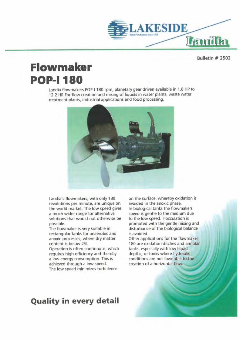
FlowmakerPOP-I 180
Landia flowmakers POP-I 180 rpm, planetary gear driven available in 1.8 HP to12.2 HR For flow creation and mixing of liquids in water plants, waste watertreatment plants, industrial applications and food processing.
Landia's flowmakers, with only 180revolutions per minute, are unique onthe world market. The low speed givesa much wider range for alternativesolutions that would not otherwise bepossible.The flowmaker is very suitable inrectangular tanks for anaerobic andanoxic processes, where dry mattercontent is below 2%.Operation is often continuous, whichrequires high efficiency and therebya low energy consumption. This isachieved through a low speed.The low speed minimizes turbulence
on the surface, whereby oxidation isavoided in the anoxic phase.In biological tanks the flowmakersspeed is gentle to the medium dueto the low speed. Flocculation ispromoted with the gentle mixing anddisturbance of the biological balanceis avoided.Other applications for the flowmaker180 are oxidation ditches and annulartanks, especially with low liquiddepths, or tanks where hydraulicconditions are not favorable to thecreation of a horizontal flow.
Quality in every detail

FlowmakerPOP-1 180
n Performance and specifications:Article no.
(460 V)
Motor
size HP
Motor
Motor
series
rpm
Propeller
rpm
Performance
approx. gpm
Weight
lb
1128398 1AM" 00 Y
'900 80 ii 2420 , 21 &mart, 1128301 180 3410 =Er 238 r12.4 100 ‘Prl- 900
-
1128302 3.6 112
900 180 5060 262 4
1128303 4.9 112
900 180 6600 284
1128304 6.5 132
900 180 9020 365
1128305 9.0 132
900 180 12100 460
1128307 12.2 160
900 180 16940 532
n Motor:3-phase AC motor, 60 Hz, voltage: 460V.
All specifications on performances are applicable for Water. Optional propeller types andmotors are available for specific mixing applications.
n Materials:Motor casing:
Cast iron AISI A48-40BOil chamber:
Cast iron AISI A48-40BPropeller:
Steel AISI A570 Gr 50Gear shaft:
Steel AISI 9840 sealed against the liquidScrews:
Steel/acidproof stainless steel
The flowmaker can be supplied with a propeller of stainless steel or with special coating.2-component coating is recommended.
Special sealing systems available for very aggressive or very abrasive mediums.• Propeller shaped for optimum flow• Triple shaft sealing system against the medium• Sturdy gear giving the propeller ideal rotations/efficiency• Pressure tested waterproof motor casing IP68 rated• Motor casing with stator in isolation class F, thermal sensors imbedded in windings• Can be supplied with explosion proof motor• Mast systems are available with multiple mounting and adjustment
configurations, also available in stainless steel and can be customized perthe application requirements
The text and technical data given may not be reproduced partly or completely without permission from Landia N5We reserve the right to make technical alterations.CA01 A.C15-1 5.02.01
LAKESIDEn .. r.^..,Sa..
P.O. Box 8448 • Bartlett, IL 60103630/837-5640 • fax: 630/837-5647E-mail: [email protected]
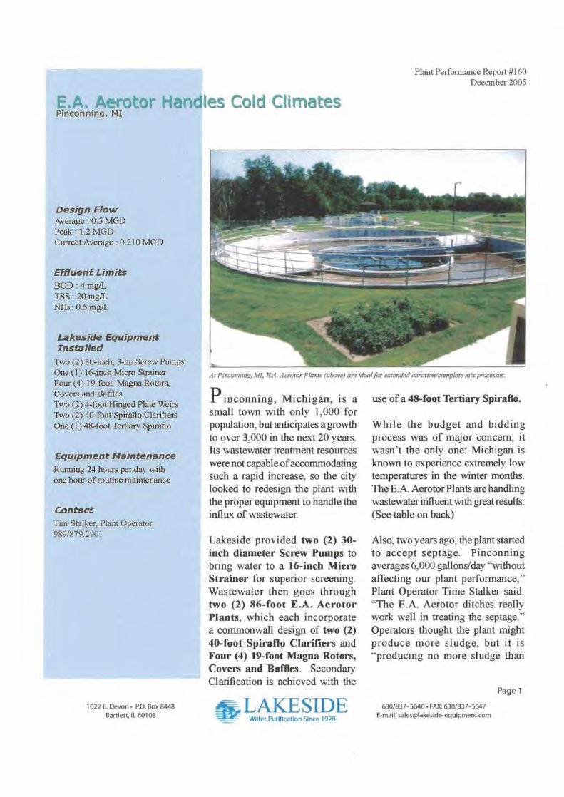
P inconning, Michigan, is asmall town with only 1,000 forpopulation, but anticipates a growthto over 3,000 in the next 20 years.Its wastewater treatment resourceswere not capable of accommodatingsuch a rapid increase, so the citylooked to redesign the plant withthe proper equipment to handle theinflux of wastewater.
Lakeside provided two (2) 30-inch diameter Screw Pumps tobring water to a 16-inch MicroStrainer for superior screening.Wastewater then goes throughtwo (2) 86-foot E.A. AerotorPlants, which each incorporatea commonwall design of two (2)40-foot Spiraflo Clarifiers andFour (4) 19-foot Magna Rotors,Covers and Baffles. SecondaryClarification is achieved with the
Plant Performance Report #1160December 2005
use of a 48-foot Tertiary Spiraflo.
While the budget and biddingprocess was of major concern, itwasn't the only one: Michigan isknown to experience extremely lowtemperatures in the winter months.The E.A. Aerotor Plants are handlingwastewater influent with great results.(See table on back)
Also, two years ago, the plant startedto accept septage. Pinconningaverages 6,000 gallons/day "withoutaffecting our plant performance,"Plant Operator Time Stalker said."The E.A. Aerotor ditches reallywork well in treating the septage. "Operators thought the plant mightproduce more sludge, but it is"producing no more sludge than
E,A. Aerotor Hand!Pinconning, MI
Design FlowAverage : 0.5 MGDPeak : 1.2 MGDCurrect Average : 0.210 MGD
Effluent Limits
BOD : 4 mg/LTSS : 20 mg/LNH3 : 0.5 mg/L
Lakeside EquipmentInstalled
Two (2) 30-inch, 3-hp Screw PumpsOne (1) 16-inch Micro StrainerFour (4) 19-foot Magna Rotors,Covers and BafflesTwo (2) 4-foot Hinged Plate WeirsTwo (2) 40-fool Spiraflo ClarifiersOne (1) 48-foot Tertiary Spiraflo
Equipment Maintenance
Running 24 hours per day withone hour of routine maintenance
Contact
Tim Stalker, Plant Operator989/879.2901
es Cold Climates
At Pinconning, MI, E.A. Aerotor Plants (above) are ideal for extended aeration/complete mix processes.
Page 1
1022 E. Devon • P.O. Box 8448
Bartlett, IL 60103IJAKESIDF
Water Purification Since 1928
630/837-5640• FAX: 630/837-5647E-mail: [email protected]
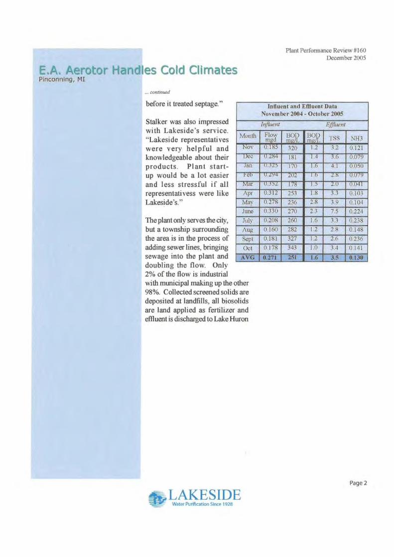
EA. Aerotor HandlPinconning, MI
Plant Performance Review #160December 2005
Influent and Effluent DataNovember 2004- October 2005
Influent
Effluent
Month Flowmgd
BO^/T
Dm:
13ODmgIL TSS NH3
Nov 0.185 320 1.2 3.2 0.121Dec 0.284 lgt I.4 3.6 0.079
Jan 0.325 170 1.6 4.1 0.050
0.294 202 1.6 2.8 0.079
Mar 0.352 178 1.5 2.0 0.041
Apr 0.312 253 1.8 3.3 0.103
May 0.278 236 2.8 3.9 0.104
June 0.330 270 2.3 7.5 0.224
July 0.208 260 1.6 3.3 0.238
Aug 0.160 282 1.2 2.8 0.148
Sept 0.181 327 1.2 2.6 ' 0.236
Oct 0.178 343 1.0 3.4 0.141
AVG 0.271 251 1.6 3.5 0.130
Page 2
T .AKE SIDEWater Purification Since 1928
es Cold Climates
... continued
before it treated septage."
Stalker was also impressedwith Lakeside's service."Lakeside representativeswere very helpful andknowledgeable about theirproducts. Plant start-up would be a lot easierand less stressful if allrepresentativess were likeLakeside's."
The plant only serves the city,but a township surroundingthe area is in the process ofadding sewer lines, bringingsewage into the plant anddoubling the flow. Only2% of the flow is industrialwith municipal making up the other98%. Collected screened solids aredeposited at landfills, all biosolidsare land applied as fertilizer andeffluent is discharged to Lake Huron

APPENDIX D
Disc Filters

Tertiary Filtration Description:
The Discfilter system, two (2) units (one duty, one redundant) of model HSF1706-1 F, will filter a peak equalizedflow of 0.5 MGD. The system is designed to provide solids removal to a final effluent average concentration of J0mg/L TSS and will operate at a loading rate in accordance with Ten States Standards. The Discfilter units will beconstructed of stainless steel.
The Kruger scope of supply includes the filter elements, drive system, local control system, backwash pump,engineering support, freight, start-up services, spare parts and one-year warranty for each unit supplied.
The KrugerlHydrotechDiscfilter presents several advantages compared to other filtration technologies. Theseadvantages include:
• Compact footprint.• Minimal mechanical equipment.• Simple automated control system.• Easy maintenance without the need to drain the system.• Minimal backwash requirements (approx. 1-3% of influent flow).• Typical head-loss through filter: Normal 8-10" Maximum 12"• Proven installations in New York State.
The following Kruger/Hydrotech Discfilter design is based on the information listed below. Table 1 summarizes theinfluent and effluent design criteria for this project.
Table 1: Influent & Effluent Design CriteriaWastewater Composition
Peak Influent TSS, mg/LAverage Influent TSS, mg/LAverage Effluent TSS, mg/LAverage Effluent P, mg/L
<_25<151<_10
9 Assumed2 Soluble phosphorus must be reduced to 0.6 mg/L prior to the settling phase (secondary clarification) of
the SBR system in order to ensure compliance with the indicated limit.
QvEouAWATER
Solutions & Technologies
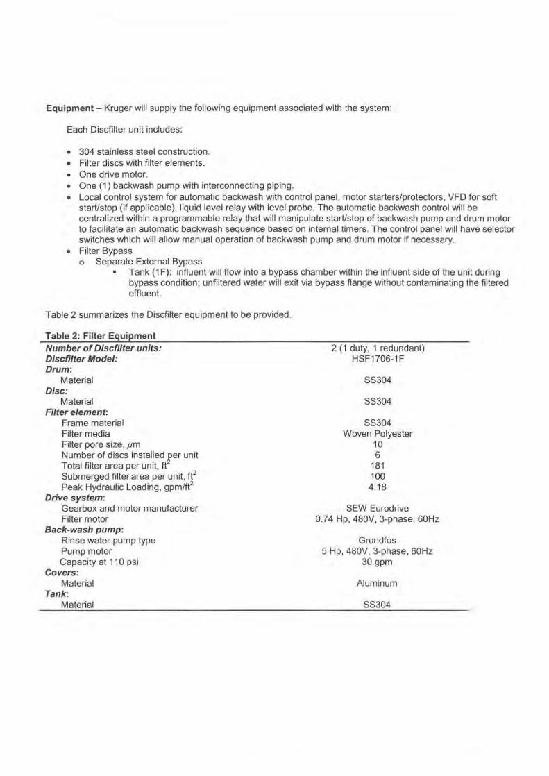
Equipment - Kruger will supply the following equipment associated with the system:
Each Discfilter unit includes:
• 304 stainless steel construction.• Filter discs with filter elements.• One drive motor.• One (1) backwash pump with interconnecting piping.• Local control system for automatic backwash with control panel, motor starters/protectors, VFD for soft
start/stop (if applicable), liquid level relay with level probe. The automatic backwash control will becentralized within a programmable relay that will manipulate start/stop of backwash pump and drum motorto facilitate an automatic backwash sequence based on internal timers. The control panel will have selectorswitches which will allow manual operation of backwash pump and drum motor if necessary.
• Filter Bypasso Separate External Bypass
n Tank (1 F): influent will flow into a bypass chamber within the influent side of the unit duringbypass condition; unfiltered water will exit via bypass flange without contaminating the filteredeffluent.
Table 2 summarizes the Discfilter equipment to be provided.
Table 2: Filter EquipmentNumber of Discfilter units:Discfilter Model:Drum:
MaterialDisc:
MaterialFilter element:
Frame materialFilter mediaFilter pore size, pmNumber of discs installed per unitTotal filter area per unit, ftSubmerged filter area per unit, ft2Peak Hydraulic Loading, gpm/ft 2
Drive system:Gearbox and motor manufacturerFilter motor
Back-wash pump:Rinse water pump typePump motorCapacity at 110 psi
Covers:Material
Tank:Material
2 (1 duty, 1 redundant)HSF1706-1 F
SS304
SS304
SS304Woven Polyester
106
1811004.18
SEW Eurodrive0.74 Hp, 480V, 3-phase, 60Hz
Grundfos5 Hp, 480V, 3-phase, 60Hz
30 gpm
Aluminum
SS304
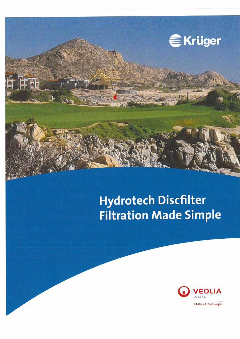
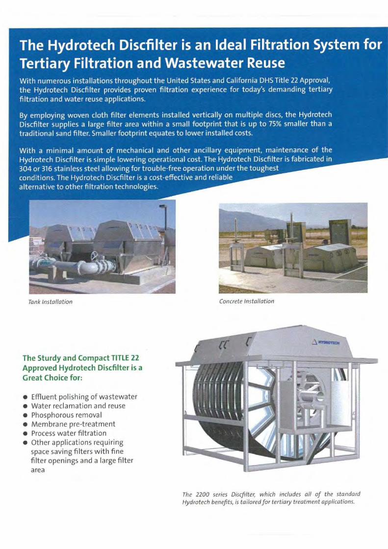
The Hydrotech Discfilter is an Ideal Filtration System forTertiary Filtration and Wastewater ReuseWith numerous installations throughout the United States and California DHS Title 22 Approval,the Hydrotech Discfilter provides proven filtration experience for today's demanding tertiaryfiltration and water reuse applications.
By employing woven cloth filter elements installed vertically on multiple discs, the HydrotechDiscfilter supplies a large filter area within a small footprint that is up to 75% smaller than atraditional sand filter. Smaller footprint equates to lower installed costs.
With a minimal amount of mechanical and other ancillary equipment, maintenance of theHydrotech Discfilter is simple lowering operational cost. The Hydrotech Discfilter is fabricated in304 or 316 stainless steel allowing for trouble-free operation under the toughestconditions. The Hydrotech Discfilter is a cost-effective and reliablealternative to other filtration technologies.
Tank installation Concrete Installation
The Sturdy and Compact TITLE 22Approved Hydrotech Discfilter is aGreat Choice for:
• Effluent polishing of wastewater• Water reclamation and reuse• Phosphorous removal• Membrane pre-treatment• Process water filtration• Other applications requiring
space saving filters with finefilter openings and a large filterarea
The 2200 series Discfilter, which includes all of the standardHydrotech benefits, is tailored for tertiary treatment applications.

Partial Submergence
Filtering at partial submergence allows multipleoperational benefits. The effluent collection tankdoes not need to be drained to clean the Discfiltermedia since the backwash cleaning system isabove the submergence level. Additionally, flowthrough the filter is continuous, even during abackwash cleaning cycle the filter never goes offline. The un-submerged media is ready and cleanfor immediate use, allowing the filter to handlehigh solids spikes while maintaining treatment.
Moving Backwash Spray Header
The moving backwash spray header of theHydrotech Discfilter guarantees efficient cleaningof the filter media. This feature increases the lifeexpectancy of the filter media and results in a 20%savings in rinse water consumption. Thebackwash spray header also folds out to facilitatemaintenance of the spray nozzles, which can beremoved and replaced without the use of anytools.
Absolute Barrier
The modular filter panels consist of a wovenpolyester filter media, which is held within astainless steel frame. With a precise pore size, thewoven material of the Discfilter media allows forbetter filtration than filters containing non-wovenmedia with an "average" pore size. The wovenfilter media provides an absolute barrier and isavailable in various pore sizes from 10 µm to 1 mm.
Filter Expansion
The modular panels provide a simple means ofmaintaining and expanding the Discfilter. Thelargest filter can contain up to 20 discs; however, afilter containing fewer discs can be installed withmore discs added as flow rates increase.
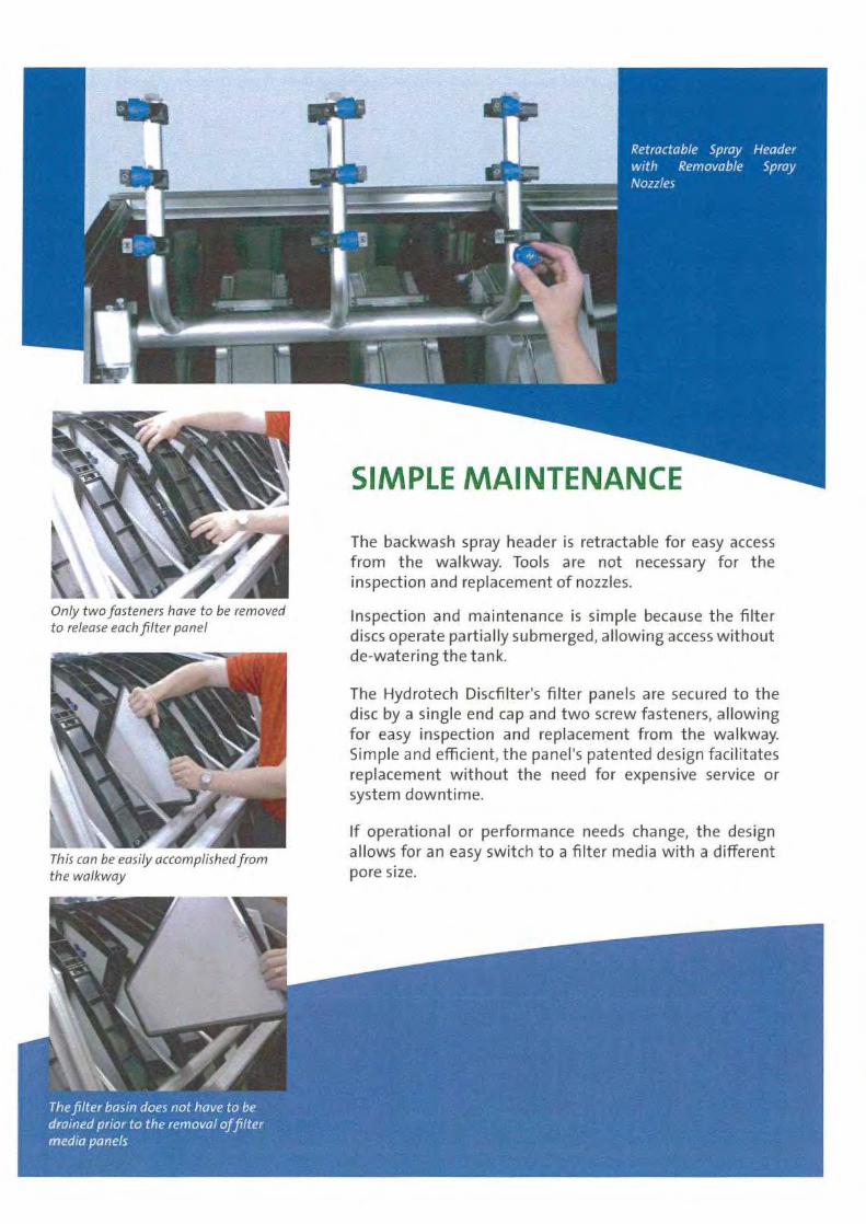
SIMPLE MAINTENANCE
The backwash spray header is retractable for easy accessfrom the walkway. Tools are not necessary for theinspection and replacement of nozzles.
Inspection and maintenance is simple because the filterdiscs operate partially submerged, allowing access withoutde-watering the tank.
The Hydrotech Discfilter's filter panels are secured to thedisc by a single end cap and two screw fasteners, allowingfor easy inspection and replacement from the walkway.Simple and efficient, the panel's patented design facilitatesreplacement without the need for expensive service orsystem downtime.
If operational or performance needs change, the designallows for an easy switch to a filter media with a differentpore size.
Only two fasteners have to be removedto release each filter panel
This can be easily accomplished fromthe walkway

The influent flows by gravity into the filter discs from the center drum. Solids are separated from thewater by the filter media mounted on the two sides of the discs, which are partially submerged. With thisarrangement, the solids are retained within the filter discs while only the clean water flows to the outsideof the discs and into the collection tank. This allows for the effective removal of large solids and floatablematerial. Maintenance is reduced since there is no accumulation of solids in the tank.
ADVANTAGES
PROCESS
During normal operation, the discs remain static untilthe water level in the inlet channels rises to a specificpoint, which then automatically initiates thebackwash cycle. The filtered effluent provides a perfectsource of backwash water, eliminating the need for aseperate source of cleaning water or an additionalclean water collection tank.
Clean effluent is pumped to the backwash sprayheader and nozzles, washing solids into the collectiontrough as the discs rotate. The backwash waterrequired is 1-3 percent of the total flow to the filter,depending on solids loading rates. Maximumallowable head loss in continuous operation is 12inches.
• Meets or exceeds Title 22 requirementat various influent turbidity levels andhydraulic loading rates up to 6 gpm/W
• Consistently produces quality effluentdespite high-solids loadings, upsets andbackwash cycles
• Available with self-contained tankage
• Capable of installation in an existing basin
• Requires far less space than otherfiltration methods
• All units supplied with aluminum covers
• Simplified control system and lessinstallation costs than other filtrationtechnologies

APPENDIX E
UV Disinfection
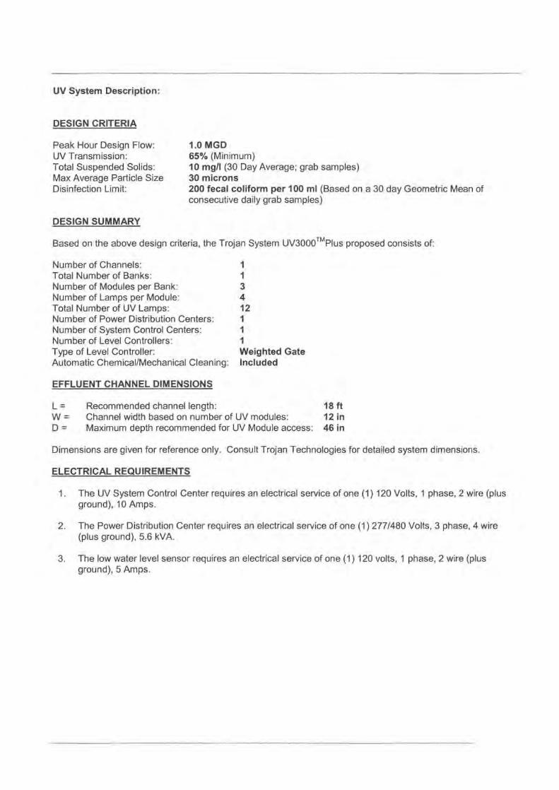
UV System Description:
DESIGN CRITERIA
1.0 MGD65% (Minimum)10 mg/l (30 Day Average; grab samples)30 microns200 fecal coliform per 100 ml (Based on a 30 day Geometric Mean ofconsecutive daily grab samples)
DESIGN SUMMARY
Based on the above design criteria, the Trojan System UV3000 TM Plus proposed consists of:
Number of Channels:
1Total Number of Banks:
1Number of Modules per Bank:
3Number of Lamps per Module:
4Total Number of UV Lamps:
12Number of Power Distribution Centers:
1Number of System Control Centers:
1Number of Level Controllers:
1Type of Level Controller:
Weighted GateAutomatic Chemical/Mechanical Cleaning: Included
EFFLUENT CHANNEL DIMENSIONS
L =
Recommended channel length:
18 ftW =
Channel width based on number of UV modules:
12 inD =
Maximum depth recommended for UV Module access: 46 in
Dimensions are given for reference only. Consult Trojan Technologies for detailed system dimensions.
ELECTRICAL REQUIREMENTS
1. The UV System Control Center requires an electrical service of one (1) 120 Volts, 1 phase, 2 wire (plusground), 10 Amps.
2. The Power Distribution Center requires an electrical service of one (1) 277/480 Volts, 3 phase, 4 wire(plus ground), 5.6 kVA.
3. The low water level sensor requires an electrical service of one (1) 120 volts, 1 phase, 2 wire (plusground), 5 Amps.
Peak Hour Design Flow:UV Transmission:Total Suspended Solids:Max Average Particle SizeDisinfection Limit:
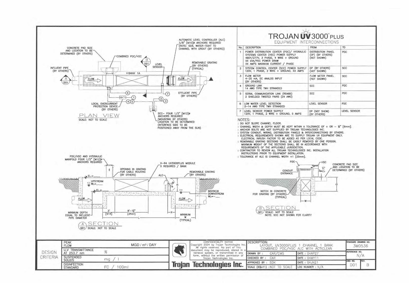
CONCRETE PAD SIZEAND LOCATION TO BE
DETERMINED (BY OTHERS)
TROJAN UV3000 PLUSEQUIPMENT INTERCONNECTIONS
POWER DISTRIBUTION CENTER (PDC)/ HYDRAULICSYSTEMS CENTER (HSC) POWER SUPPLY480Y/27N, 3 PHASE, 4 WIRE + GROUNDXX kVA/PDC POWER DRAWXX AMPS MAXIMUM CURRENT / PHASE
SYSTEM CONTROL CENTER (SCC) POWER SUPPLY120V, 1 PHASE, 2 WIRE + GROUND, XX AMPS
5 SERIAL COMMUNICATION UNK (R5485)
SCC2 SHIELDED TWISTED PAIRS (24 AWG)
NOTES:DO NOT SLOPE CHANNEL FLOOR.CHANNEL WIDTH & DEPTH MUST BE KEPT WITHIN A TOLERANCE OF + OR - 1A" [6mm].ANCHOR BOLTS ARE NOT SUPPUED BY TROJAN TECHNOLOGIES INC.SYSTEM CONDUIT, WIRING, DISTRIBUTION PANELS & INTERCONNECTIONS BY OTHERS.ELECTRICAL REQUIREMENTS SHOWN ARE TO SUPPLY TROJAN UV EQUIPMENT ONLY.ELECTRICAL INRUSH FACTOR TO BE ADDED AS PER LOCAL CODE.
REMOVABLE GRATING SECTIONS SHALL BE EASILY REMOVED BY ONE PERSON.MAXIMUM WEIGHT OF THE SECTIONS SHALL BE IN ACCORDANCE WITHREQUIREMENTS OF THE APPLICABLE JURISDICTION.
CONTRACTOR TO REVIEW ALL TROJAN TECHNOLOGIES INC. INSTALLATIONINSTRUCTIONS PRIOR TO EQUIPMENT INSTALLATION.
TOLERANCE AT ALC IS CHANNEL WIDTH +1 [25mm].
AUTOMATIC LEVEL CONTROLLER (ALC)3/8' [M10]0 ANCHORS REQUIRED(NOTE: SEAL WATER-TIGHT TOCHANNEL WTTH GROUT (BY OTHERS))
PDC/HSC AND HYDRAULICMANIFOLD FOUR 1/2 " [M12]0
ANCHORS REQUIRED
DP (BY OTHERS)(140T SHOWN)
DISTRIBUTION PANEL(DP) (BY OTHERS)(NOT SHOWN)
PDC
SCC
TO
SCC
FLOW METER PANEL(NOT SHOWN)
SCC
PDC
PDC
6 LOW WATER LEVEL DETECTION2-14 AWG TYPE TWH STRANDED
LEVEL SENSOR PDC
7 LEVEL SENSOR POWER SUPPLY120V, 1 PHASE, 2 WIRE + GROUND, 5 AMPS
DP (NOT SHOW)(BY OTHERS)
LEVEL SENSOR
CONCRETE PAD SIZEAND LOCATION TO BEDETERMINED (BY OTHERS)
NOTCH IN CONCRETEFOR GRATING (BY OTHERS)
(TYPICAL)
C)SECTION1 SCALE:SCALE: NOTNOT TOTO SCALEALEQ01
PEAKFLOW
DISINFECTIONSTANDARD
FC / 100mI
CONFIDENTIALITY NOTICECopyright 2004 by Trojan Technologies Inc.
All rights reserved. No part of thisdocument moy be reproduced, stored in a
retrieval system, or transmitted in anyform, without the written permission of
Trojan Technologies Inc.
Trojan Technologies Inc.
STANDARD DRAWING NO.
3MO536REFERENCE NO.
N/A
DWG NO.
REV.
DO1
B
MGD! m3/ DAYDESCRIPTION:
LAYOUT, UV3000PLUS 1 CHANNEL 1 BANKCOMBINED PDC/HSC ALC WITH ACTICLEAN
DESIGNCRITERIA
U.V TRANSMITTANCEAT 253.7 nm
%
SUSPENDEDSOLIDS mg/I
DATE : 04JN21APPROVED BY : SDK
DRAWN BY :
CAR/CMS
CHECKED BY : CAR
DATE : 04AP27
DATE : 04MY11
SCALE (8%x11) :NOT TO SCALE
LOG NUMBER : N/A
NOTE: SCC NOT SHOWN FOR CLARITY
FROMDESCRIPTION
VSCC- FOUR 1/2" [M12]dANCHORS REQUIRED(MOUNTING BY OTHERS)LOCATION TO BE DETERMINED(INTERFACE SIDE TO BEPOSITIONED AWAY FROM THE SUN)
01---- 00LOCAL OVERCURRENT
PROTECTION DEVICE(BY OTHERS)
PLAN VIEWSCALE: NOT TO SCALE
No.
1
2
3
4
FLOW METER4-20 mA, DC ANALOG INPUT(BY OTHERS)GROUND LINK14 AWG TYPE TWH STRANDED
TROJAN UV3000 PLUS
WASTEWATER DISINFECTION
•
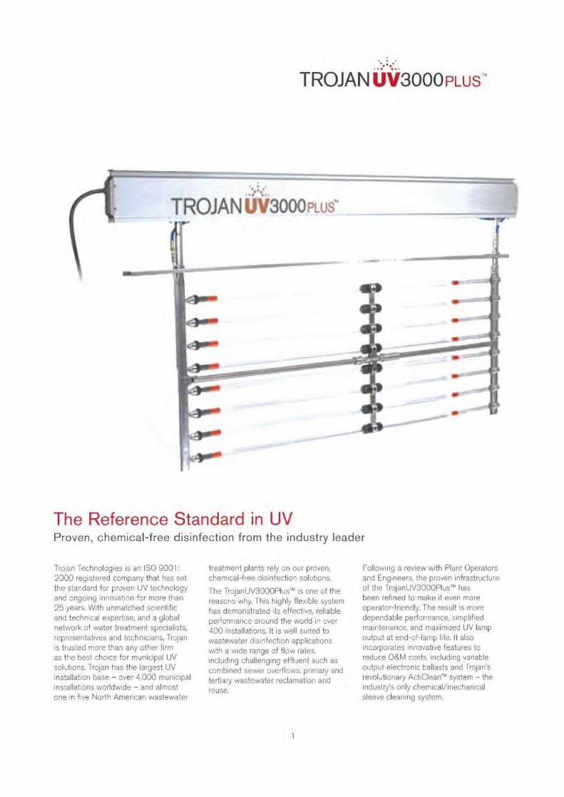
TROJAN UV3000PLUSTM
The Reference Standard in UVProven, chemical-free disinfection from the industry leader
Trojan Technologies is an ISO 9001:2000 registered company that has setthe standard fcr proven UV technologyand ongoing innovation for more than25 years. With unmatched scientificand technical expertise, and a globalnetwork of water treatment specialists,representatives and technicians, Trojanis trusted more than any other firmas the best choice for municipal UVsolutions. Trojan has the largest UVinstallation base - over 4,000 municipalinstallations worldwide - and almostone in five North American wastewater
treatment plants rely on our proven,chemical-free disinfection solutions.
The TrojanUV3000Plus'" is one of thereasons why. This highly flexible systemhas demonstrated its effective, reliableperformance around the world in over400 installations. It is well suited towastewater disinfection applicationswith a wide range of flow rates,including challenging effluent such ascombined sewer ove rflows. primary andtertiary wastewater reclamation andreuse.
Following a review with Rant Operatorsand Engineers, the proven infrastructureof the TrojanUV3000PIus TM' hasbeen refined to make it even moreoperator-friendly. The result is moredependable performance, simplifiedmaintenance, and maximized UV lampoutput at end-of-lamp life. It alsoincorporates innovative features toreduce O&M costs, including variableoutput electronic ballasts and Trojan'srevolutionary ActiClean T system - theindustry's only chemical/mechanicalsleeve cleaning system.
1
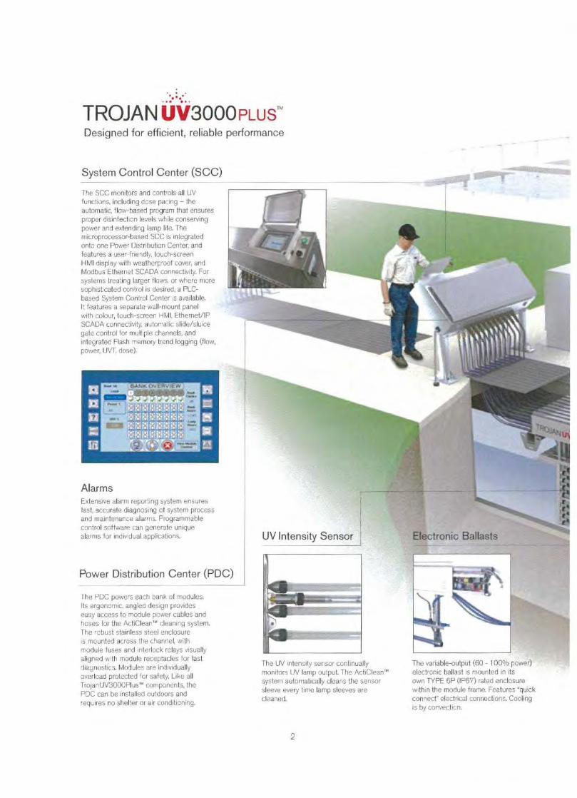
TROJAN UV3000 PLUS TMDesigned for efficient, reliable performance
System Control Center (SCC)
The SCC monitors and controls all UVfunctions, including dose pacing - theautomatic, flow-based program that ensuresproper disinfection levels while conservingpower and extending lamp life. Themicroprocessor-based SCC is integratedonto one Power Distribution Center, andfeatures a user-friendly, touch-screenHMI display with weatherproof cover, andModbus Ethernet SCADA connectivity. Forsystems treating larger flows, or where moresophisticated control is desired, a PLC-based System Control Center is available.It features a separate wall-mount panelwith colour, touch-screen HMI, EthernetllPSCADA connectivity, automatic slide/sluicegate control for multiple channels, andintegrated Flash memory trend logging (flow,power, UVT. dose).
AlarmsExtensive alarm reporting system ensuresfast, accurate diagnosing of system processand maintenance alarms. Programmablecontrol software can generate uniquealarms for individual applications.
Power Distribution Center (PDC)
I he PDC powers each bank of modules.Its ergonomic, angled design provideseasy access to module power cables andhoses for the ActiClean'" cleaning system.The robust stainless steel enclosureis mounted across the channel. withmodule fuses and interlock relays visuallyaligned with module receptacles for lastdiagnostics. Modules are individuallyoverload protected for safety. Like allTrojanUV3000Plus'"' components, thePDC can be installed outdoors andrequires no shelter or air conditioning.
The UV intensity sensor continuallymonitors UV lamp output. The ActiClean''system automatically cleans the sensorsleeve every time lamp sleeves arecleaned.
The variable-output (60 - 100°.Ys power)electronic ballast is mounted in itsown TYPE 6P (IF67) rated enclosurewithin the module frame. Features "quickconnect" electrical connections. Coolingis by convection.
2
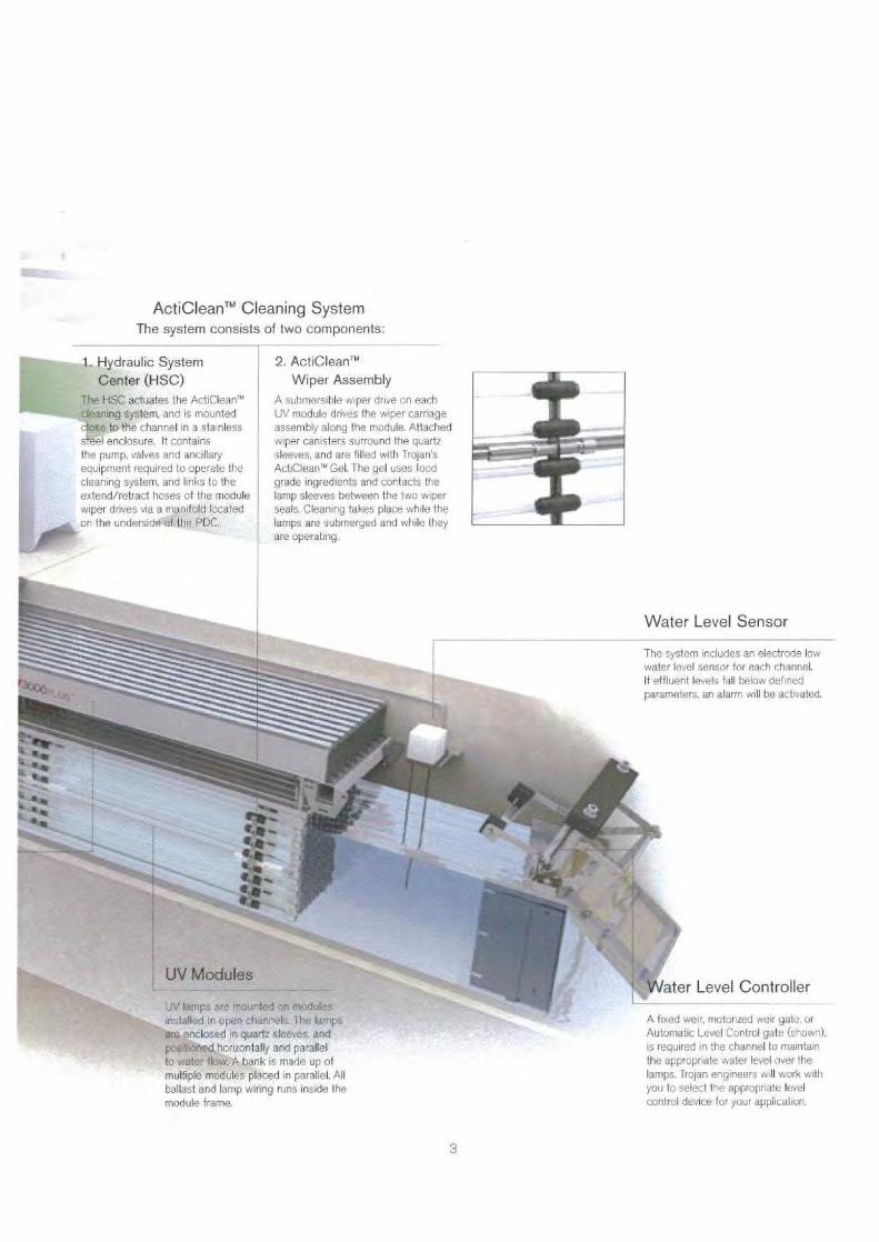
ActiClean TM Cleaning SystemThe system consists of two components:
1. Hydraulic SystemCenter (HSC)
The HSC actuates the ActiClean''cleaning system, and is mountedclose to the channel in a stainlesssteel enclosure. It containsthe pump, valves and ancillaryequipment required to operate thecleaning system, and links to theextend/retract hoses of the modulewiper drives via a manifold locatedon the underside of the PDC.A^skk
UV lamps are mounted an modules
2. ActiClean TMWiper Assembly
A submersible wiper drive on eachUV module drives the wiper carriageassembly along the module. Attachedwiper canisters surround the quartzsleeves, and are filled with Trojan'sActiClean' Gel. The gel uses foodgrade ingredients and contacts thelamp sleeves between the two wiperseals, Cleaning takes place while thelamps are submerged and while theyare operating.
The system includes an electrode lowwater level sensor for each channel.If effluent levels fall below definedparameters, an alarm will be activated.
installed in open channels. The lampsare enclosed in quartz sleeves, andpositioned horizontally and parallelto water flow. A bank is made up ofmultiple modules placed in parallel. Allballast and lamp wiring runs inside themodule frame.
A'fixed weir, motorized weir gate, orAutomatic Level Control gate (shown),is required in the channel to maintainthe appropriate water level over thelamps. Trojan engineers will work withyou to select the appropriate levelcontrol device for your application
3
Key BenefitsTrojanUV3000Plus T"
Increased operator, community and environmental safety.The TrojanUV3000Plus TM uses environmentally-friendly ultraviolet light - the safest
alternative for wastewater disinfection. No disinfection by-products are created, and no
chemicals must be transported, stored or handled.
Well suited to changing regulations. Trojan UV systems do not have any negative
impact on receiving waters and do not produce disinfection by-products, making them a
strategic, long-term choice as regulations become increasingly stringent.
Most efficient UV system available versus competitive low-pressure, high-output
(LPHO) or amalgam lamp-based systems.
Reduces operating costs by as much as 30% per year. Long-lasting
amalgam lamps and variable-output ballasts optimize UV output to meet wastewater
conditions and maximize system efficiency versus competitive UV systems.
Proven disinfection based on actual dose delivery testing (bioassay validation), and
over 400 TrojanUV3000PIus TM installations worldwide. Real-world, field performance data
eliminates sizing assumptions resulting from theoretical dose calculations.
Dual-action sleeve cleaning system improves performance andreduces labor costs. Automatic ActiClean T' chemical/mechanical cleaning system
maintains sleeve transmittance of at least 95%, and works online - eliminating the need to
remove modules from the channel.
Reduced installation costs. The compact TrojanUV3000Plus TM can be retrofitted
into existing chlorine contact tanks, and comes pre-tested, pre-assembled and pre-wired to
minimize installation costs.
Outdoor installation flexibility. The entire TrojanUV3000PIus TM system can be
installed outdoors, eliminating the need and costs of a building, shelter, and air conditioning
for ballast cooling.
Guaranteed performance and comprehensive warranty. Trojan systems
include a Lifetime Performance Guarantee, the best lamp warranty in the industry, and use
lamps from multiple approved suppliers. Ask for details.
4
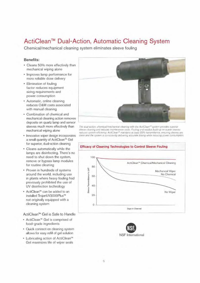
ActiClean'" Dual-Action, Automatic Cleaning SystemChemical/mechanical cleaning system eliminates sleeve fouling
Benefits:• Cleans 50% more effectively than
mechanical wiping alone
• Improves lamp performance formore reliable dose delivery
• Elimination of foulingfactor reduces equipmentsizing requirements andpower consumption
• Automatic, online cleaningreduces O&M costs associatedwith manual cleaning
• Combination of chemical andmechanical cleaning action removesdeposits on quartz lamp and sensorsleeves much more effectively than
The dual-action, chemical/mechanical cleaning with the ActiClean'' system provides superior
mechanical wiping alone
sleeve cleaning and reduces maintenance costs. Fouling and residue build-up on quartz sleevesreduces system efficiency. ActiClean" maintains at least 95°,o transmittance, ensuring sleeves are
• Innovative wiper design incorporates clean and the system is consistently delivering accurate dosing while reducing power consumption.
a small quantity of ActiClean'" Gelfor superior, dual-action cleaning
Days in Channel
ActiClean'' Gel is Safe to Handle• ActiClean'" Gel is comprised of
food-grade ingredients
• Quick connect on cleaning systemallows for easy refill of gel solution
• Lubricating action of ActiClean''Gel maximizes life of wiper seals
Efficacy of Cleaning Technologies to Control Sleeve Fouling• Cleans automatically while the
lamps are disinfecting. There's noneed to shut down the system,
100
remove or bypass lamp modulesfor routine cleaning
80-
• Proven in hundreds of systemsaround the world, including use so-in plants where heavy fouling hadpreviously prohibited the use ofUV disinfection technology
40-
• ActiClean'" can be added to aninstalled TrojanUV3000PIusTM
20-
not originally equipped with acleaning system
o
ActiClean.n Chemical/Mechanical Cleaning
Mechanical WiperNo Chemical
NSF International
5
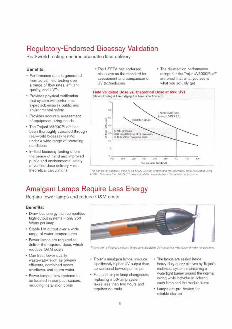
Regulatory-Endorsed Bioassay ValidationReal-world testing ensures accurate dose delivery
Benefits:• Performance data is generated
from actual field testing overa range of flow rates, effluentquality, and UVTs
• Provides physical verificationthat system will perform asexpected; ensures public andenvironmental safety
• Provides accurate assessmentof equipment sizing needs
- The TrojanUV3000PIus T' hasbeen thoroughly validated throughreal-world bioassay testingunder a wide range of operatingconditions
• In-field bioassay testing offersthe peace of mind and improvedpublic and environmental safetyof verified dose delivery - nottheoretical calculations
Amalgam Lamps Require Less EnergyRequire fewer lamps and reduce O&M costs
• The USEPA has endorsed
• The disinfection performancebioassays as the standard for
ratings for the TrojanUV3000PIus TMassessment and comparison of
are proof that what you see isUV technologies
what you actually get
Field Validated Dose vs. Theoretical Dose at 65% UVT(Before Fouling & Lamp Aging Are Taken into Account)
Theoretical Dose(using UVDIS 3.1)
Validated Dose
At 400 Ipm/lamp,there is a difference of 16 mWs/cm',or 42% of the Theoretical Dose
0 100
150
200
250
300
350
400
450
500
Flow per Lamp (Ipm/lamp)
This shows the validated dose of an actual working system and the theoretical dose calculated usingUVD/S. Note that the UVD/S 3.1 dose calculation overestimates the system performance.
70
60
to
Trojan's high efficiency amalgam lamps generate stable UV output in a wide range of water temperatures.
Benefits:- Draw less energy than competitive
high-output systems - only 250Watts per lamp
▪ Stable UV output over a widerange of water temperatures
• Fewer lamps are required todeliver the required dose, whichreduces O&M costs
• Can treat lower qualitywastewater such as primaryeffluents, combined seweroverflows, and storm water
• Fewer lamps allow systems tobe located in compact spaces,reducing installation costs
• Trojan ' s amalgam lamps producesignificantly higher UV output thanconventional low-output lamps
• Fast and simple lamp changeouts;replacing a 50-lamp systemtakes less than two hours andrequires no tools
- The lamps are sealed insideheavy-duty quartz sleeves by Trojan 'smulti-seal system, maintaining awatertight barrier around the internalwiring while individually isolatingeach lamp and the module frame
• Lamps are pre-heated forreliable startup
6

Amalgam Lamps Maintain Maximum UV OutputTrojan lamps deliver 98% of full UV output after more than one year of use
Benefits:- Trojan ' s high efficiency, amalgam
lamps deliver the most consistentUV output over their 15 monthlamp life
• Trojan lamps have 20% lessdecline in UV output after 12,000hours of use compared tocompetitive UV lamps
• Validated performance dataassures you of reliable dosedelivery and prolonged lamp life
Decrease in UV Lamp Output Over Time
98%Trojan Amalgam Lamp
90 -
6a
1400
2.000
3000
4,000
5,000
6,000
7400
8.000
9,000
10,000
1400 12,000
Lamp Aga (Hours)
The lamps used on the TrojanUV3000Plus' system have been independently validated to maintain98% of original output after 12,000 hours (15 months) of operation.
Competitor Nl Lamp
Competitor 4$2 Lamp 70%
Open-Channel Architecture Designed for Outdoor InstallationCost-effective to install and expand
Benefits:• Compact, open-channel design
allows cost-effective installationin existing effluent channelsand chlorine tank basins
• System can be installedoutdoors to reduce capitalcosts - no building, shelter orair conditioning is required
• Gravity-fed design eliminatescosts of pressurized vessels,piping and pumps
• Scalable architecture allowsprecise sizing - reduces capitaland O&M costs associatedwith oversizing
• Modular design is readilyexpandable to meet newregulatory or capacityrequirements
- Trojan's thorough designapproach ensures that effluentquality, upstream treatmentprocesses, and O&M needsare addressed in systemconfigurations
• Horizontal lamp mounting deliversoptimal hydraulic performance.Induces turbulence and dispersion,maximizing wastewater exposureto UV output
The TrojanUV3000P1us'"' system deliversflexibility and cost savings through its simpleinstallation in existing channels and chlorinecontact tanks. The system can be situatedoutdoors with no additional building, shelter orcooling requirements.
7
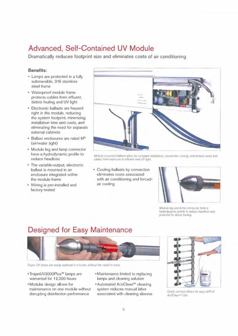
Advanced, Self-Contained UV ModuleDramatically reduces footprint size and eliminates costs of air conditioning
Benefits:• Lamps are protected in a fully
submersible, 316 stainlesssteel frame
• Waterproof module frameprotects cables from effluent,debris fouling and UV light
• Electronic ballasts are housedright in the module, reducingthe system footprint, minimizinginstallation time and costs, andeliminating the need for separateexternal cabinets
• Ballast enclosures are rated 6P(air/water tight)
• Module leg and lamp connectorhave a hydrodynamic profile toreduce headloss
• The variable-output, electronicballast is mounted in an
• Cooling ballasts by convectionenclosure integrated within
eliminates costs associatedthe module frame
with air conditioning and forced-
- Wiring is pre-installed and air cooling
factory-tested
Module leg and lamp connector have ahydrodynamic profile to reduce headloss andpotential for debris fouling.
Trojan UV lamps are easily replaced in minutes without the need for tools.
• TrojanUV3000PIus T" lamps are -Maintenance limited to replacingwarranted for 12,000 hours
lamps and cleaning solution
▪Modular design allows for • Automated ActiCleanTM cleaningmaintenance on one module without
system reduces manual labordisrupting disinfection performance
associated with cleaning sleeves
Module-mounted ballasts al/ow for compact installation, convection cooling, and protect wires andcables from exposure to effluent and UV light.
Quick connect allows for easy refill ofActiClean" M Gel.
8

TROJAN UV3000FLus TM
System Specifications..5
em Characteristics.• Y TrojanUV3000P1:es"'
Typical Applications Wide range of wastewater treatment plants
Lamp Type High-efficiency Amalgam
Ballast Type Electronic. variable output (60 to 100% power)
Input Power Per Lamp 250 Watts
Lamp Configuration Horizontal. parallel flower.
Module Canfiguratien 4, 6 or 8 lamps per module
Level Control Device Options ALC. fixed weir or motorized weir gate
Water Level Sensor 1 electrode low water level seam per channel
&mere Ratings r
Mod...le Frame / Ballast Enclosure TYPE 6P (IP67) / TYPE 6P (IP68)pp ea._
All Other Enclosures TYPE 4X (11856)
Ballast Cooling Method Convection; no air conditioning or forced air required
Installation Location Indoor or outdoor -&eve Cleaning System:
Optional Automatic Chemical/Mechanical Cleaning SystemActiClean '"' Cleaning System
ActiClean l " Cleaning Gel Non-corrosive. operator-triendly_ire
1.0Recommended Fouling Factor
I
System Control Center:
y
F3 'r
?
Controller Microprocessor or PLC-based
Analog Inputs (Typical) Flow (4-20 mA) and UVT (4-20 rrA)
i Discrete Outputs (Typical) Bank status, =man alarms and SCADA communication.e re
Maximum Distance from UV Chem-el 500 ft (152 m)
rical Requirements:
Power Distr buticn Center 208Y/120V, 3 phase. 4 wire + GND 60 Hz (Max, A modules per FIX)480Y/277V, 3 phase, 4 wire + GND. 60 Ha
380Y/223V. 3 phase. 4 wire + GND, 50/60 Hz400Y/230V, 3 phase, 4 woe + GND. 50/60 Hz415Y/240V, 3 phase, 4 wire + GND, 50/60 Hz
System Control Center (stand alone) 190V, single phase ; 2 wire + GND, 60 'Hz 1.8 kVA220/230/240V, single phase, 2 wire + GND, 50/60 Hz, 1.8kVA
ce_ere
Hydraulic System Center (for ActiClean'°) 208V, 3 phase, 3 wire + GND, 60 Hz380/400/415 V. 3 phase, 3 wire + GND, 50/60 Hz
480 V, 3 phase : 3 wire + GND, 60 Hzor
2.5kVA HSC powered from PDC
Water Level Sensor 24VDC powered from P3C
Find out how your wastewater treatment plant can benefit from the TrojanUV3000PIus T" - call us today.
Head Office (Canada)3020 Gore RoadLondon, Ontario, Canada N5V 477Telephone: (519) 457-3400Fax: (519) 457-3030
www.lrojanuv.com
Trojan UV Technologies UK Limited (UK): +44 1905 77 1 1 17Trojan Technologies (The Netherlands): +31 70 391 3020Trojan Technologies (France): +33 1 6081 0516Trojan Technologies Espana (Spain): +34 91 564 5757Trojan Technologies Deutschland GmbH (Germany): +49 6024 634 75 80Hach/Trojan Technologies (China) 86-10-65150290
Products ie this brochure may be covered by one or more of the following patents:U.S. 4.872,980:5.006,244; 5,418.370; RE 36,896: 8.342,188, 6.635.613: 5,546,269; 8.663,318; 8,719.491 6.830,697: . 7,018,975Can. 1,327,877: 2.11 7,040; 2.239,925Other patents pending.^.
^. a'^-ntad in Canada. Cepyriyht 20(]7. Trojan Techn::lacr res, London, Ontario, Canada,bar pant of this publication may be reproduced. stored in a re1('eaal system, or transmitted in any norm or by any meansrabbet,' this wearer. pnrmisaion of Trojan Teol nolorcie .MWW-003 (0107) TROW-1040
TROJAN UVWATER CONFIDENCE"

APPENDIX F
Sludge Holding
p
i
i
i
i
i
i
i
i
i
wastewater 1 reatment systems
HW.,AGK 7'R 1'1'UTN'I
POPHATIOI\- & MAIN 1 I'HNAN
INSfRUC1'ION
PROJECT NO.: PES-0163-TPROJECT NAME: Red Hook CommonsLOCATION: Red Hook, N YPURESTREAM MODEL: PES-25, PST-14
I
DATE: 12/28/2006
PIIrIllitPUlII ESNo,
'
LLC,
Advanced Environmental Treatment Systems
10584 Dixie Highway • Walton, Kentucky 41094 • Phone: (859) 377-9898 • Fax: (859) 371-3577Website: www.purestreaminc.com • e-mail: purestream &tuse.net
C i'
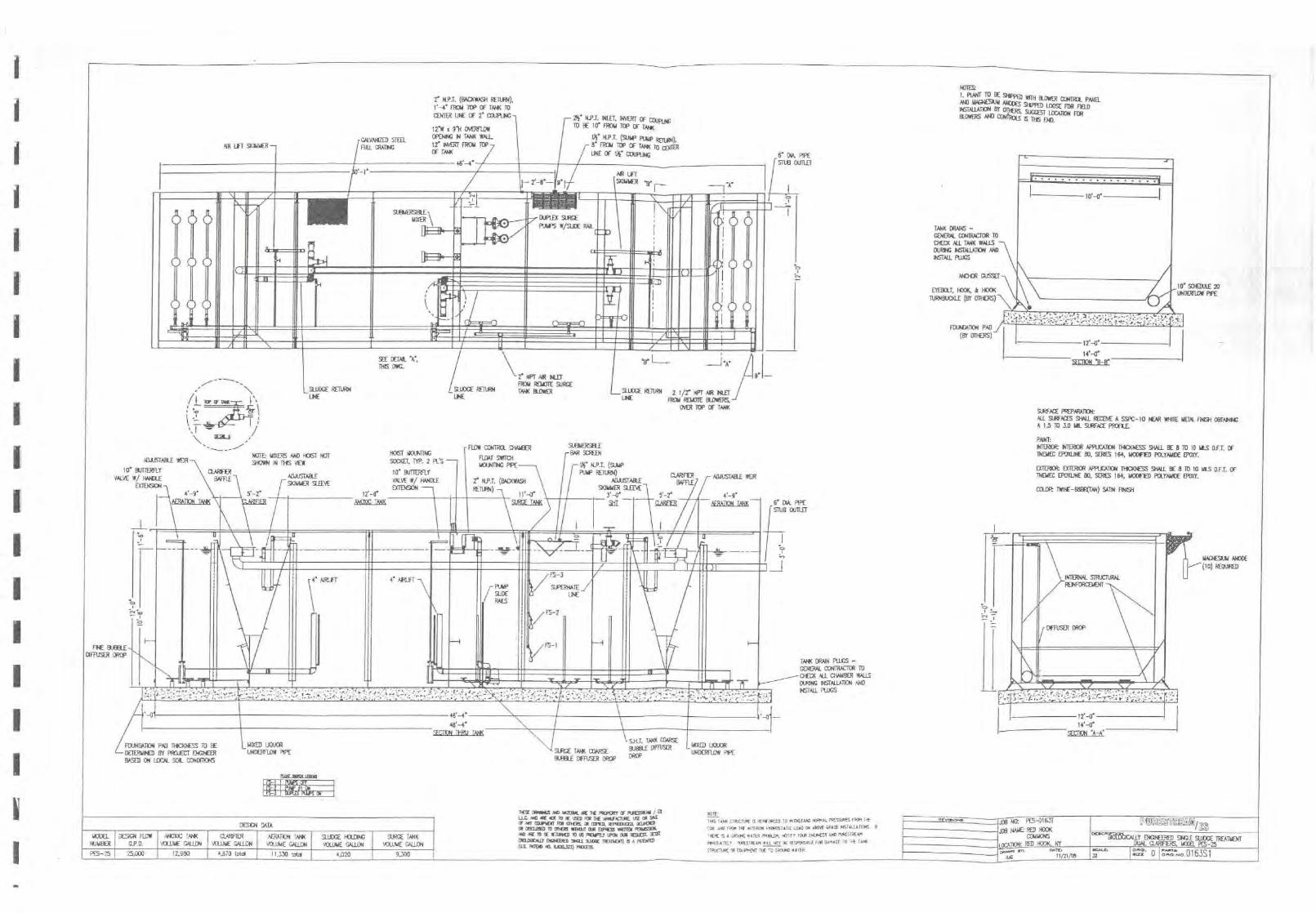
1-
0
M
Y
--
iII
sm.
^
1o1
r:^ii!"1-i
II
t^
11 II11
+w1n4:111
11 llr
'i
► 71a
^E
wr
1A
sirN
K^Wp
VI
f~'
•I
Nei
aMn
om
.I
I' ^I=
L_
MI
..9
---0
•
•--
`
f
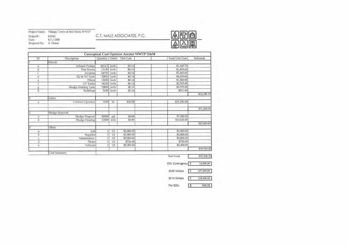
C.T. MALE ASSOCIATES, P.C.Project Name: Village/Town of Red Hook WWTP
Project# :
8.8341Date:
8/1/2008Prepared By:
R. Flores
MEE
Conceptual Cost Opinion Aerotor WWTP O&MID Description Quantity
Units
Unit Cost
I
I
I Total Unit Cost I
SubtotalsElectric
a Influent Pumps 8212.5 kwh $0.14 $1,149.75b Fine Screen 13140 kwh $0.14 $1,839.60c Aerolors 54750 kwh $0.14 $7,665.00d EQ & DO Tank 32850 kwh $0.14 $4,599.00e Filters 12000 kwh $0.14 51,680.00f UV Tanks 18250 kwh $0.14 $2,555.00g Sludge Holding Tank 32850 kwh $0.14 $4,599.00h Buildings 3650 kwh $0.14 $511.00
$24,598.35
2 Labora Contract Operator 1.040 hr $30.00 531,200.00
$31,200.00
3 Sludge Removala Sludge Disposal )
90000 gal $0.08 $7,200.00Sludge Hauling 12000 mile $0.89 $10,620.00
$17,820.004 Other
a Lab 1 1.5 53,001.00 $3,000.00b Supplies 1 LS $5,000.00 $5,000.00c Maintenance 1 LS 55,000.00 $5,000.00d Phone 1 LS $720.00 $720.00e Vehicals 1 IS $5,200.00 $5,200.00
$18,920.00(Cost Summary
Sub-Total
15% Contingency
2008 Dollars
2010 Dollars
Per EDU
I
$92,538.351
$
14,0{10.00
1$ 107,000.00 1
$
118,000.00
1$ 346.00 1

APPENDIX H
Form E and Cost Opinions
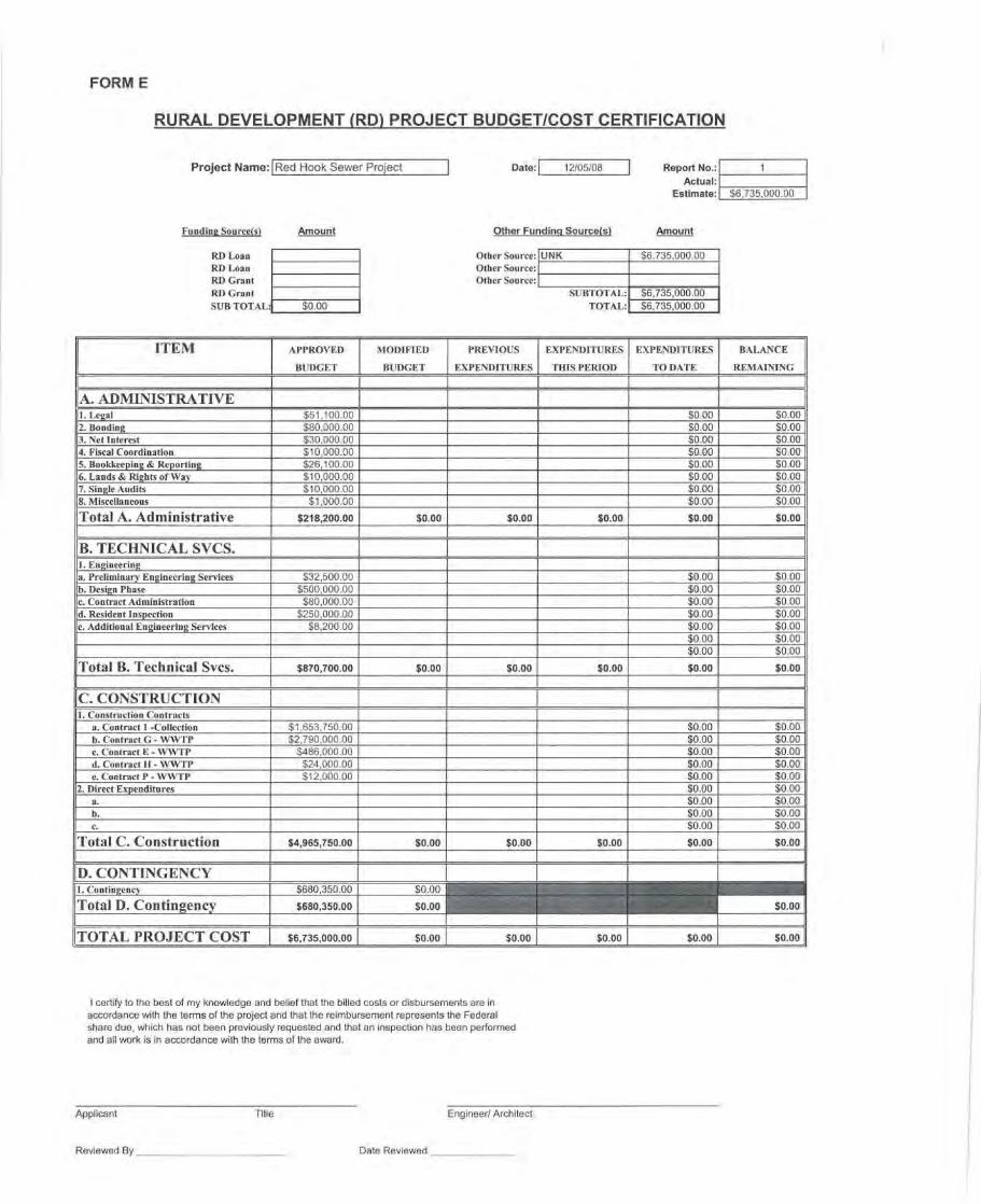
FORM E
RURAL DEVELOPMENT (RD) PROJECT BUDGETICOST CERTIFICATION
Project Name: Red Hook SewerProject 12/05/08 Report No.:Actual:
Estimate: $6,735,000.00
Date:
Funding Sourcetsi
Amount
Other Funding Source(sl
Amount
RD loanRD LoanRD GrantRD GrantSUB TOTAL:
$0.00
Other Source:Other Source:Other Source:
$6,735,000.00
$6, 735,000.00$6, 735,000.00
UNK
SUBTOTAL:TOTAL:
ITEM APPROVED
BUDGET
MODIFIED
BUDGET
PREVIOUS
EXPENDITURES
EXPENDITURES
THIS PERIOD
EXPENDITURES
TO DATE
BALANCE
REMAINING
1 I 1A. ADMINISTRATIVE
'1. Legal $51,100.00 $0.00 $0.002. Bonding $80,000.00 $0.00 $0.003. Net Interest $30,000.00 $0.00 $0.004. Fiscal Coordination $10,000.00 $0.00 $0.005. Bookkeeping & Reporting $26,100.00 $0.00 $0.00 _6. Lands & Rights of Way $10,000.00 $0.00 $0.007. Single Audits $10,000.00 $0.00 $0.008. Miscellaneous $1,000.00 $0.00 $0.00
Total A. Administrative $218,200.00 $0.00 $0.00 $0.00 $0.00 $0.00
B. TECHNICAL SVCS.1. Engineeringa. Preliminary Engineering Services $32,500.00 $0.00 $0.00b. Design Phase $500,000.00 $0.00 $0.00c. Contract Administration $80,000.00 $0.00 $0.00d. Resident inspection $250,000.00 $0.00 $0.00c. Additional Engineering Services $8,200.00 $0.00 $0.00
$0 00 $0.00$0.00 $0.00
Total B. Technical Svcs. $870,700.00 $0.00 $0.00 $0.00 $0.00 $0.00
C. CONSTRUCTION1. Construction Contracts
a. Contract I -Collection $1,653,750.00 $0.00 $0.00b. Contract G - WWTP $2,790,000.00 $0.00 $0.00c. Contract E - WWTP $486,000.00 $0.00 $0.00d. Contract H - WWTP $24,000.00 $0.00 $0.00e. Contract P WWTP $12,000.00 $0.00 $0.00
2. Direct Expenditures $0.00 $0.00a. $0.00 $0.00b. $0.00 $0.00c. $0.00 $0.00
Total C. Construction $4,965,750.00 $0.00 $0.00 $0.00 $0.00 $0.00
D. CONTINGENCY1. Contingency
T o t a l D . C on tingency$680,350.00
$680,350.00
$0.00
$0.00 $0.00
TOTAL PROJECT COST $6,735,000.00 $0.00 $0.00 $0.00 $0.00 $0.00
I certify to the best of my knowledge and belief that the billed costs or disbursements are inaccordance with the terms of the project and that the reimbursement represents the Federalshare due, which has not been previously requested and that an inspection has been performedand all work is in accordance with the terms of the award.
Applicant
Title
Engineer/ Architect
Reviewed By Date Reviewed
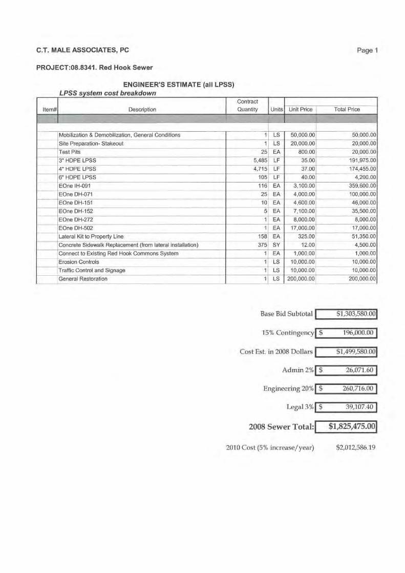
C.T. MALE ASSOCIATES, PC
Page 1
PROJECT:08.8341. Red Hook Sewer
ENGINEER'S ESTIMATE (all LPSS)LPSS system cost breakdown
Contract
Item# Description Quantity Units
Unit Price Total Price
LS 50,000.00 50,000.00Mobilization & Demobilization, General Conditions
Site Preparation- Stakeout 1 LS 20,000.00 20,000.00
Test Pits 25; EA 800.001 20, 000.00-3" HDPE LPSS 5,485 LF 35.00 , 191,975.00
14" HOPE LPSS 4,715 LF 37.00 174,455.00
16" HDPE LPSS 105 LF 40.00 4,200.00
EOne IH-091 116 EA 3,100.00 359,600.00
EOne DH-071 25 EA 4,000.00 100,000.00
EOne DH-151 10 EA 4,600.00 46,000.00
1EOne DH-152 5 EA 7,100.00 35,500.00
EOne DH-272 1,
EA 8,000.00 8,000.00
EOne DH-502 1 EA 17, 000.00 17, 000.00
Lateral Kit to Property Line 158 EA 325.00; 51,350.00
Concrete Sidewalk Replacement (from lateral installation) 375 SY 12.00 , 4,500.00
Connect to Existing Red Hook Commons System 1 EA 1,000 00 1,000.00
Erosion Controls 1 LS 10,000.00 10,000.00
'Traffic Control and Signage LS 10,000.00 10,000.00
General Restoration 1 LS 200,000.00 200,000.00
Base Bid Subtotal $1,303,580.001
15% Contingency 196,000.00
Cost Est. in 2008 Dollars $1,499,580.001
Admire 2% $ 26,071.60
Engineering 20% $ 260,716.00
Legal 3% $ 39,107.40
2008 Sewer Total: $1,825,475.001
2010 Cost (5% increase/year)
$2,012,586.19

APPENDIX I
Subsurface Disposal
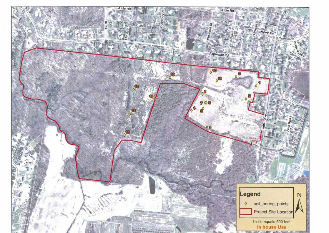
soil_boring_points
Project Site Location

2
MEMORANDUM
DAl F:
December 6, 2007
TO:
Gary Male
FROM:
Joseph N. Carpenter
CC:
John Munsey, Robert Flores, Kyle Purdy
RE:
Waters of the U.S. Preliminary Walkover ReportRed HookTown and Village of Red Hook, Dutchess County, New YorkC.T. Male Project No.: 06.6213
The purpose of this internal memorandum is to summarize results of a preliminarywalkover to assess the magnitude and type of wetlands and other waters of the U.S. onthe approximately seventy (70) acre project site located to the west of Linden Avenue inthe Town and Village of Red Hook, Dutchess County, New York (refer to Site LocationMap).
On November 27, 2007 a C.T. Male Associates, P.C. (C.T. Male) environmental servicesrepresentative field reviewed the project site. The following provides information onthe field reviews, map reviews, permitting considerations, and a summary andrecommendations section.
FIELD REVIEW
A field review was conducted within the project site to assess the presence or absence ofwaters of the U.S. wetland areas were identified and their approximate boundariessketched (refer to Attachment A, Field Sketch Map). Please note that although theproject site was reviewed during the field visit, several wetlands on site (PotentialWetland 1, 2, 3, 4, 5, 6, 7, 8, 9) were not flagged with wetland delineation boundaryflagging due to time constraints. Therefore, a complete wetland delineation should beconducted before any development planning activities occur.
Wetlands 1, 2, 3, 4 and 5 were observed to be associated with the northern floodplain ofthe Saw Kill. Potential Wetland 3 was observed to be characterized as a floodedagricultural area, connecting to the Saw Kill via Intermittent Stream 1. Wetland 5 wasobserved to be characterized as a flooded hardwood forest and was observed to connectto the Saw Kill via Intermittent Stream 2. The remaining wetland areas can be classifiedas an emergent scrub-shrub wetland with observed surface standing water.
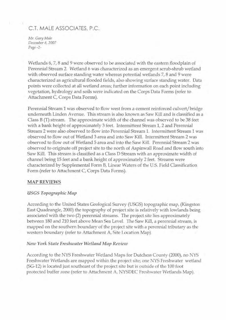
C.T. MALE ASSOCIATES, P.C.
Mr. Ganj MaleDecember 6, 2007Page -2-
Wetlands 6, 7, 8 and 9 were observed to be associated with the eastern floodplain ofPerennial Stream 2. Wetland 6 was characterized as an emergent scrub-shrub wetlandwith observed surface standing water whereas potential wetlands 7, 8 and 9 werecharacterized as agricultural flooded fields, also showing surface standing water. Datapoints were collected at all wetland areas; further information on each point includingvegetation, hydrology and soils were indicated on the Corps Data Forms (refer toAttachment C, Corps Data Forms).
Perennial Stream 1 was observed to flow west from a cement reinforced culvert/bridgeunderneath Linden Avenue. This stream is also known as Saw Kill and is classified as aClass B (T) stream. The approximate width of the channel was observed to be 38 feetwith a bank height of approximately 3 feet. Intermittent Stream 1, 2 and PerennialStream 2 were also observed to flow into Perennial Stream 1. Intermittent Stream 1 wasobserved to flow out of Wetland 3 area and into Saw Kill. Intermittent Stream 2 wasobserved to flow out of Wetland 5 area and into the Saw Kill. Perennial Stream 2 wasobserved to originate off project site to the north of Aspinwall Road and flow south intoSaw Kill. This stream is classified as a Class D Stream with an approximate width ofchannel being 15 feet and a bank height of approximately 2 feet. Streams werecharacterized by Supplemental Form B, Linear Waters of the U.S. Field ClassificationForm (refer to Attachment C, Corps Data Forms).
MAPREVIEWS
USGS Topographic Map
According to the United States Geological Survey (USGS) topographic map, (KingstonEast Quadrangle, 2000) the topography of project site is relatively with lowlands beingassociated with the two (2) perennial streams. The project site lies approximatelybetween 180 and 210 feet above Mean Sea Level. The Saw Kill, a perennial stream, ismapped on the southern boundary of the project site with a perennial tributary as thewestern boundary (refer to Attachment A, Site Location Map).
New York State Freshwater Wetland Map Review
According to the NYS Freshwater Wetland Maps for Dutchess County (2000), no NYSFreshwater Wetlands are mapped within the project site; one NYS Freshwater wetland{SG-12) is located just southeast of the project site but is outside of the 100 footprotected buffer zone (refer to Attachment A, NYSDEC Freshwater Wetlands Map).
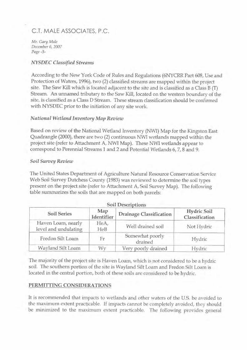
C.T. MALE ASSOCIATES, P.C.
Mr. Gang MaleDecember 6, 2007Page -3-
NYSDEC Classified Streams
According to the New York Code of Rules and Regulations (6NYCRR Part 608, Use andProtection of Waters, 1996), two (2) classified streams are mapped within the projectsite. The Saw Kill which is located adjacent to the site and is classified as a Class B (T)Stream. An unnamed tributary to the Saw Kill, located on the western boundary of thesite, is classified as a Class D Stream. These stream classification should be confirmedwith NYSDEC prior to the initiation of any site work.
National Wetland Inventory Map Review
Based on review of the National Wetland Inventory (NWI) Map for the Kingston EastQuadrangle (2000), there are two (2) continuous NWI wetlands mapped within theproject site (refer to Attachment A, NWI Map). These NWI wetlands appear tocorrespond to Perennial Streams 1 and 2 and Potential Wetlands 6, 7, 8 and 9.
Soil Survey Review
The United States Department of Agriculture Natural Resource Conservation ServiceWeb Soil Survey Dutchess County (1983) was reviewed to determine the soil typespresent on the project site (refer to Attachment A, Soil Survey Map). The followingtable summarizes the soils that are mapped on both parcels:
Soil Descriptions
Soil Series MapIdentifier
Drainage ClassificationHydric Soil
ClassificationHaven Loam, nearlylevel and undulating
HeA,HeB
Well drained soil Not Hydric
Fredon Silt Loam FrSomewhat poorly
drainedHydric
Wayland Silt Loam Wy Very poorly drained Hydric
The majority of the project site is Haven Loam, which is not considered to be a hydricsoil. The southern portion of the site is Wayland Silt Loam and Fredon Silt Loam islocated in the central portion, both of these soils are considered to be hydric.
PERMITTINGCONSIDERATIONS
It is recommended that impacts to wetlands and other waters of the U.S. be avoided tothe maximum extent practicable. If impacts cannot be completely avoided, they shouldbe minimized to the maximum extent practicable. The following provides general

C.T. MALE ASSOCIATES, P.C.
Mr. Gary MaleDecember 6, 2007Page -4-
information on wetland permitting considerations for the U.S. Army Corps ofEngineers (Corps) and the New York State Department of Environmental Conservation(NYSDEC).
Army Corps of Engineers Permits
Impacts to waters of the U.S. (including wetlands) that do not exceed 1/2 acre ofwetlands and impact greater than 300 linear feet of stream bed, may be covered underthe U.S. Army Corps NWP #39 for Commercial and Institutional Developments. Pleasenote that any impacts to waters of the U.S. (including wetlands) that may be coveredunder a NWP #39 will need a pre-construction notification (PCN), provided that allgeneral regional conditions (NY District) are followed. Generally, a compensatorymitigation plan will be required for impacts greater than 0.1 acres.
NWP 39 is not applicable if threatened or endangered species or their habitats will beadversely affected, or if the project will affect any historic properties listed ordetermined to be eligible for listing on the National Register of Historic Places. It isrecommended that file review letters be submitted to the New York State HistoricPreservation Office (SHPO), New York Natural Heritage Program and the U.S. Fish andWildlife Service (USFWS) to determine if there are any cultural resources or protectedspecies with the parcel.
Wetland impacts greater than 1/2 of an acre or impacts to more than 300 linear feet ofstream bed would require a Section 404 Individual Permit from the Army Corps ofEngineers. An Individual Permit is a lengthy process (i.e., generally over 1 year ormore), which requires a detailed alternative site analysis, mitigation plans anddemonstration of avoidance and minimization of wetland impacts.
It is important to note that some wetlands may not be regulated by the Corps based onthe Supreme Court Case, Solid Waste Agency of Northern Cook County (SWANCC) v.
United States of Army Corps of Engineers, which challenged the Corps jurisdiction overisolated waters which are not adjacent to navigable waters. The determination ofisolation is subject to field reviews by the Corps. The Corps has the final determinationwhether a wetland is considered isolated. If the Corps determines that the wetlands areisolated, then the Corps does not have jurisdiction over those wetlands. A completewetland delineation would need to be conducted to determine the possible presence ofisolated wetlands on site.

C.T. MALE ASSOCIATES, P.C.
Mr. Gan.' MaleDecember 6, 2007Page -5-
NYSDEC Permits
Since there are no NYSDEC mapped wetlands on or within 100-foot of the study area, itwould appear that a NYSDEC Fresh Water Wetlands (FWW) permit would not berequired. The NYSDEC has certified that activities authorized by the Corps NWP #39are covered under a "blanket " Section 401 Water Quality Certification provided that theactivity meets the terms and conditions of the permits. If impacts exceed the thresholdsof the " blanket" Water Quality Certification, then an individual Section 401 WaterQuality Certification must be obtained from the NYSDEC.
There is one (1) NYSDEC mapped stream with a classification of B (T) that is locatednear the boundary of the project site. If the proposed development anticipates anyimpacts to the bed or bank of this stream, an Article 15, Protection of the Waters Permitfrom NYSDEC would be required.
SUMMARY AND RECOMMENDATIONS
Nine (9) potential wetland areas were observed throughout the project site. If desired,we can provide a proposal to conduct a complete waters of the U.S. delineation on all orselect portions of the two parcels. If you have any questions regarding this letter or theattached information please feel free to contact us.
K:\Projects\066213\Env\R Preliminary Wetlands Assessment 12 06 07.doc

Attachment AFigures
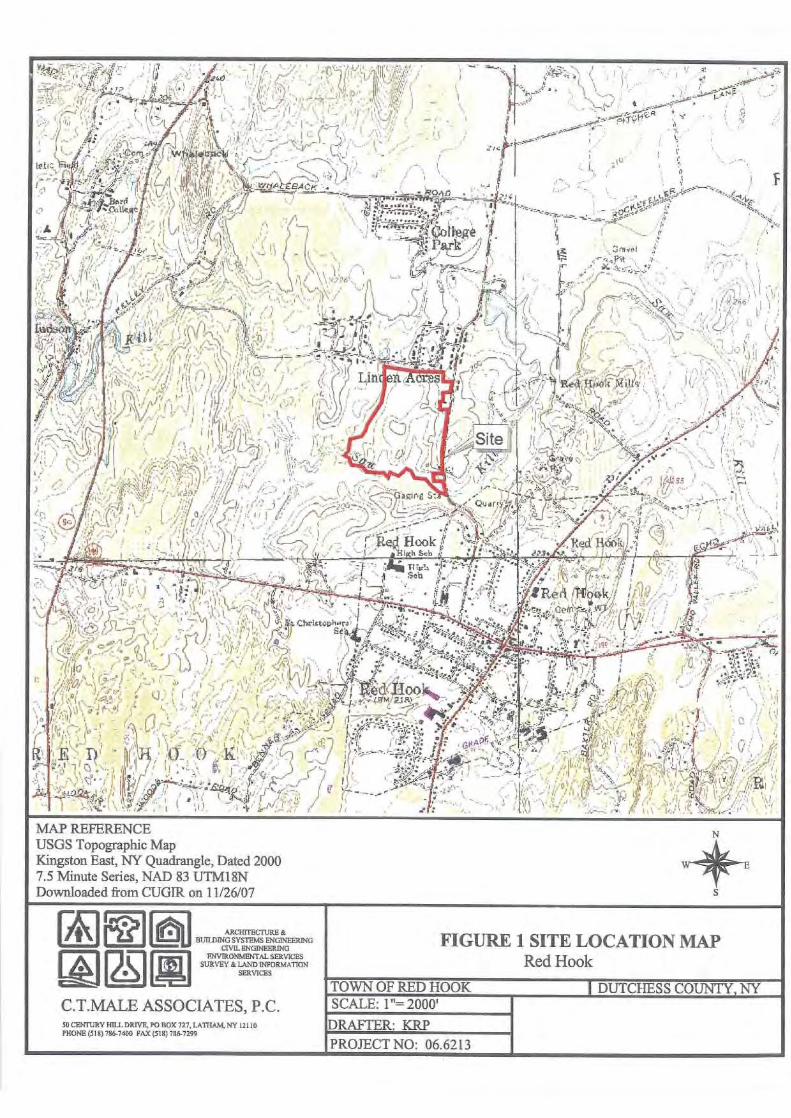
FIGURE 1 SITE LOCATION MAPRed Hook
TOWN OF RED HOOK
DUTCHESS COUNTY, NY
MAP REFERENCEUSGS Topographic MapKingston East, NY Quadrangle, Dated 20007.5 Minute Series, NAD 83 UTM18NDownloaded from CUGIR on 11/26/07
ARCHITECTURE &BUILDING SYSTEMS ENGINEERING
CIVIL ENGINEERINGENVIRONMENTAL SERVICES
SURVEY & LAND INFORMATIONSERVICES
C.T.MALE ASSOCLA I ES, P.C.50 CENTURY HILL DRIVE, PO BOX 727, LATHAM, NY 12110PHONE (518) 786-7400 FAX (518) 786-7299
SCALE: 1"= 2000'
DRAFTER: KRP
PROJECT NO: 06.6213
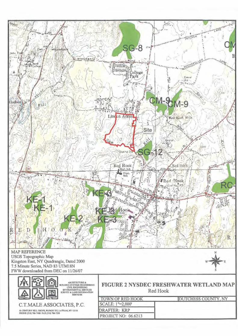
MAP REFERENCEUSGS Topographic MapKingston East, NY Quadrangle, Dated 20007.5 Minute Series, NAD 83 UTM18NFWW downloaded from DEC on 11/26/07
ARCIITECTURE &BUILDING SYSTEMS ENGINEERING
CIVIL ENGINEERINGENVIRONMENTAL SERVICES
SURVEY & LAND INFORMATIONSERVICES
C.T.MALE ASSOCIATES, P.C.54 CENTURY HILL DRIVE PO BOX 727, LATHAM, NY 12110PHONE (518) 7867400 FAX (518) 706-7299
FIGURE 2 NYSDEC FRESHWATER WETLAND MAPRed Hook
SCALE: 1"=2,000'
DRAFTER: KRPPROJECT NO: 06.6213
TOWN OF RED HOOK DUTCHESS COUNTY, NY
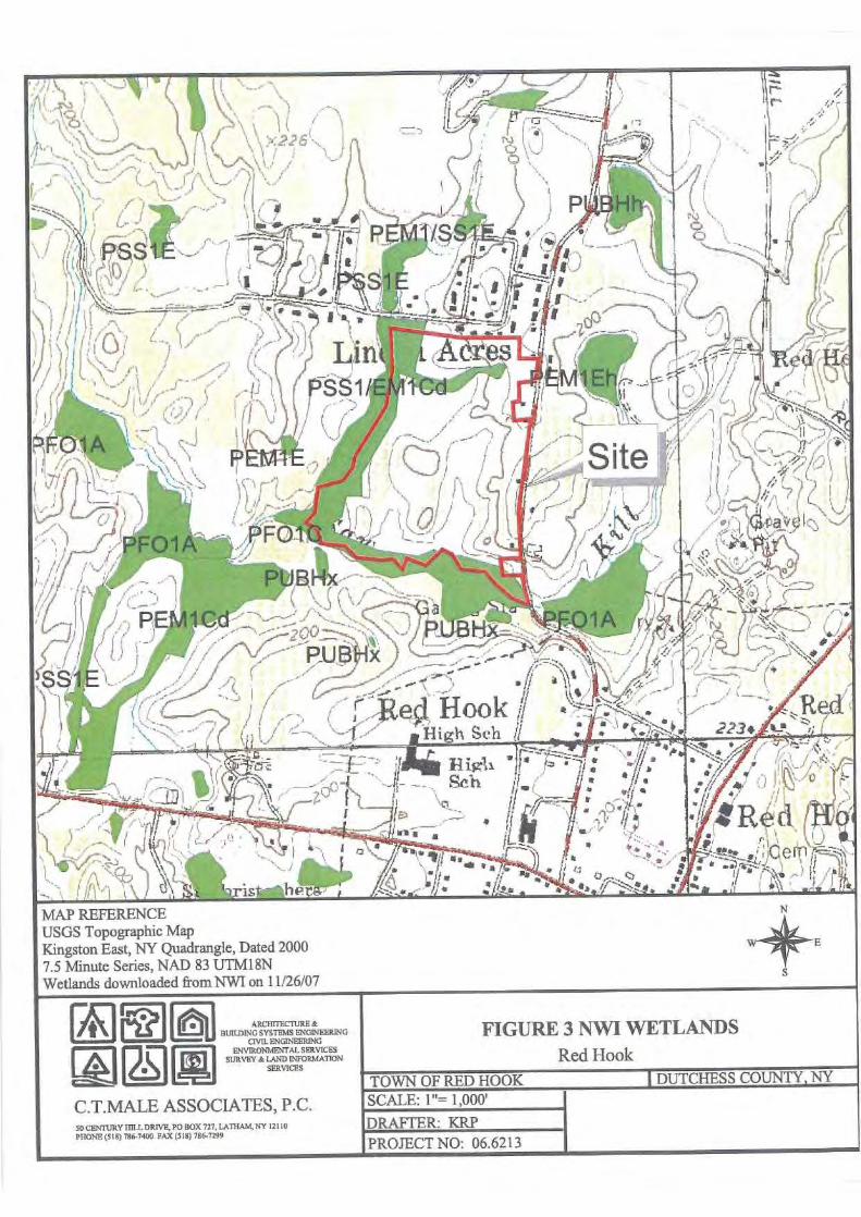
MAP REFERENCEUSGS Topographic MapKingston East, NY Quadrangle, Dated 20007.5 Minute Series, NAD 83 UTM18NWetlands downloaded from NWI on 11/26/07
C.T.MALE ASSOCIATES, P.C.50 CENIIJRY HILL DRIVE, PO BOX 727, LATIIAM, NY 12116PHONE (518) 766-7400 FAX (516) 786-7299
TOWN OF RED HOOKSCALE: 1"= 1,000'
DRAFTER: KRPPROJECT NO: 06.6213
ARCHITECTURE &BUILDING SYSTEMS ENGINEERING
CIVIL ENGINEERINGENVIRONMENTAL SERVICESLANE) 1NFO MA1IO
SURVEY &SERVICES
FIGURE 3 NWI WETLANDS
Red Hookj DUTCHESS COUNTY, NY

MAP REFERENCEUSGS Topographic MapKingston East, NY Quadrangle, Dated 19837.5 Minute Series, NAD 83Downloaded from CUGIR. on 11/26/07
Soils KeyHeA, HeB- Haven Loam, nearly level and undulatingFr-Fredon Silt Loam (hydric)Wy- Wayland Silt Loam (hydric)
ARCHITECTURE &BUILDING SYSTEMS ENGINEERING
CIVIL ENGINEERINGENVIRONMENTAL SERVICES
SURVEY & LAND INFORMATIONSERVICES
FIGURE 4 SOILS MAP
Red Hook
TOWN OF RED HOOK 1131aa._S.-IEC.T.MALE ASSOCIATES, P.C.50 CENTURY HILL DRIVE, PO BOX 727, LATHAM, NY 12110PHONE (518) 786-7400 PAX (518) 786-7299
SCALE: 1"= 500'
DRAFTER: KRPPROJECT NO: 06.6213

APPROXIMATE SCALE400
0
400 FEETI-i I-J
-,
NATIONAL FLOOD INSURANCE PROGRAM
FIRMFLOOD INSURANCE RATE MAP
TOWN OF
RED HOOK,NEW YORKDUTCHESS COUNTY
PANEL 26 OF 35(SEE MAP INDEX FOR PANELS NOT PRINTED)
COMMUNITY-PANEL NUMBER361143 0026 B
EFFECTIVE BATE:OCTOBER 16, 1984
Federal Emergency Management Agency
This is an official copy of a portion of the above referenced flood map. Itwas extracted using F-MIT On-Line. This map does not reflect changesor amendments which may have been made subsequent to the date on thetitle block. For the latest product information about National Flood InsuranceProgram flood maps check the FEMA Flood Map Store at vwvw. msc fema.gov
0

-R-0 A D
S;+e.
This is an official copy of a portion of the above referenced flood map. Itwas extracted using F-MIT On-Line. This map does not reflect changesor amendments which may have been made subsequent to the date on thetitle block. For the latest product information about National Flood InsuranceProgram flood maps check the FEMA Flood Map Store at vww rnsc,fema.gov
J
APPROXIMATE SCALE0400 400 FEE'i
NATIONAL FLOOD INSURANCE PROGRAM
FIRMFLOOD INSURANCE RATE MAP
TOWN OFRED HOOK,NEW YORKDUTCHESS COUNTY
PANEL 27 OF 35(SEE MAP INDEX FOR PANELS NOT PRINTEC)
COMMUNITY-PANEL NUMBER
361143 0027 B
EFFECTIVE DATE:OCTOBER 16. 1984
Federal Emergency Management Agency

Attachment BRepresentative Photographs
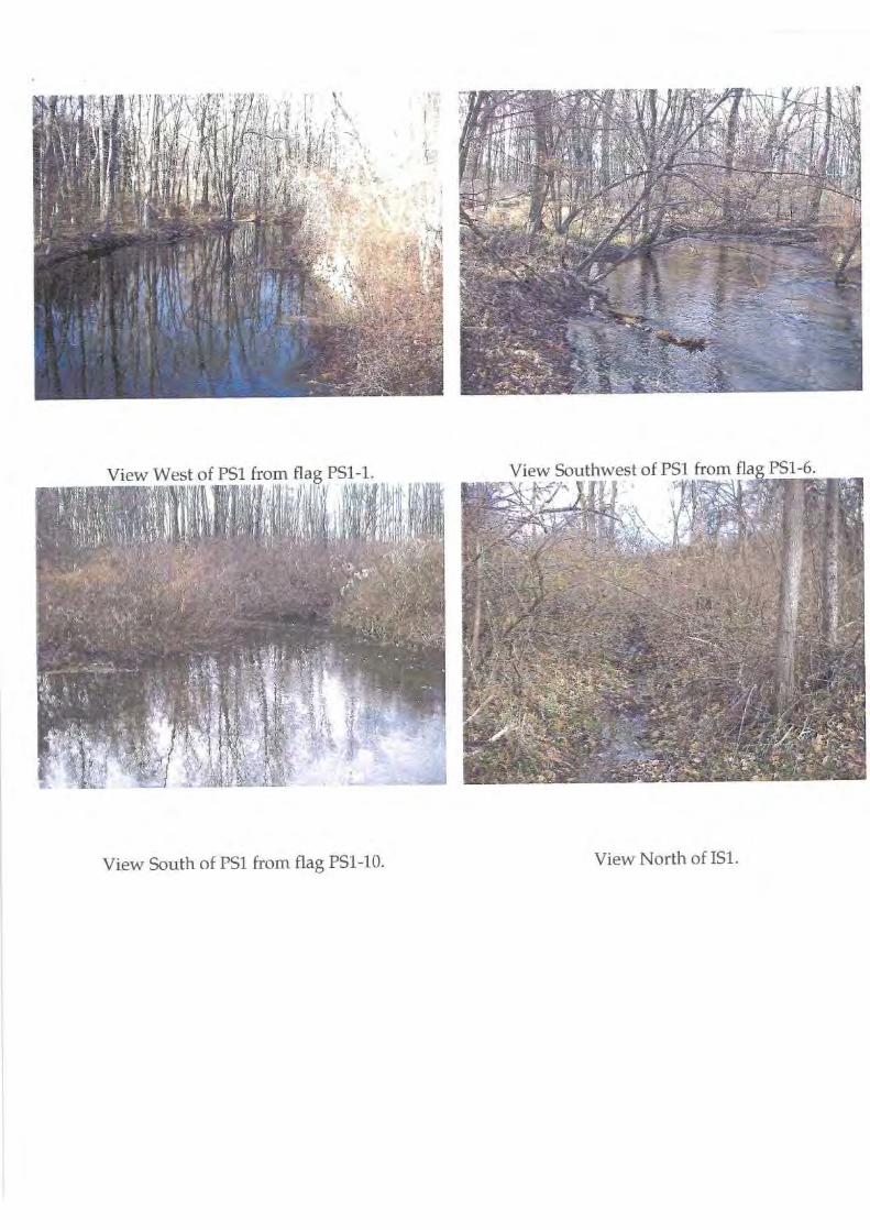
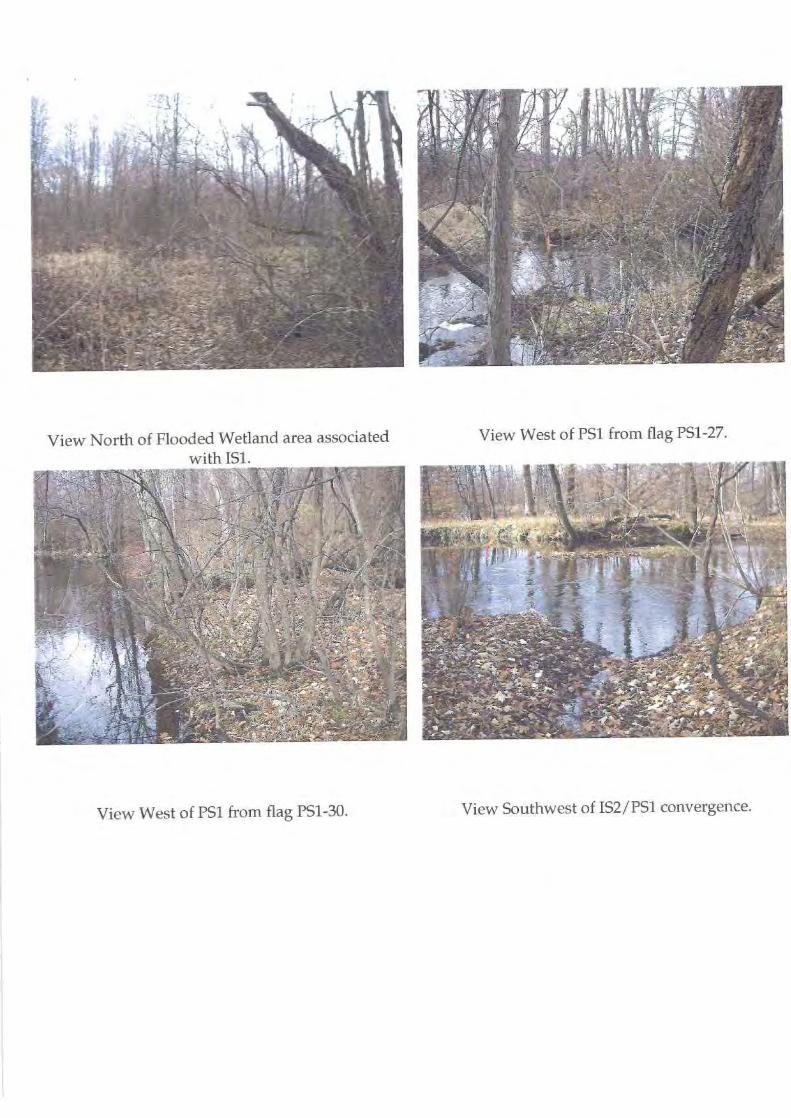
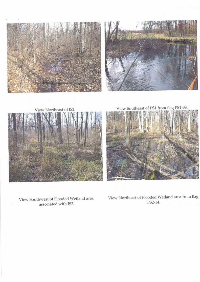
View Southwest of Flooded Wetland area
View Northeast of Flooded Wetland area from flag
associated with IS2.
PS2-14.
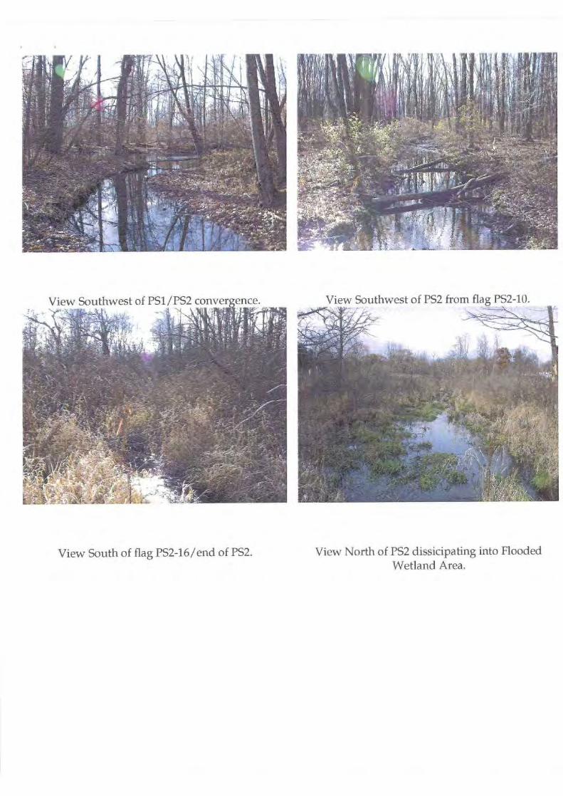
View South of flag PS2-16/end of PS2.
View North of PS2 dissicipating into FloodedWetland Area.
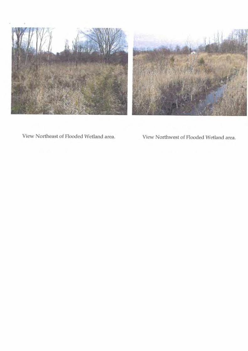
View Northeast of Flooded Wetland area.
View Northwest of Flooded Wetland area.
C.T. MALE ASSOCIATES, P.C.
Mr. Gary MaleDecember 5, 2007Page -2-
Attachment CCorps Data Forms

C.T. MALE ASSOCIATES, P.C.
Supplemental Form BLinear Waters of the U.S. Field Classification Form
Whenever an ephemeral stream, intermittent stream, or perennial stream is identified on aproject site, use this form to document field observations in support of the field interpretedstream classification.
Stream Feature: VS%- SaJ1M Watershed: Lut.t 1- 015on
Field Observations (check all that apply and describe if applicable):Surface water flow within a defined channel
3nPresence of Ordinary High Water Mark
(If OHWM is present, place a stake to mark its location).Water seeping from banks (or ice along banks in winter)Channel has a floodplain or observable bankfu]l benchPresence of fish or macroinvertebrates
c.rarimariiy erosive feature
Recent sediment deposits or accumulations in channelilgae growing on bed materials
noted plants growing in channel bed Hydric soils in sides of channel
Provide a detailed description for each (use additional space in remarks section if necessary):Antecedent weather conditions .1 iI/ZC,/07Position of channel within the drainage basin (high, middle, low)? ne ; j lcGradient of the channel (steep, moderately sloping, flat)?
n,^ , ,ly 48v'^a
Channel morphology (linear/meandering)? Width of channel? 3$ ft.
Height of bank? 3 ft.Interpreted water table position abovefr below defined channel? Awe.Bed materials (provide description of bed materials and indicate if different from surrounding ground surface):
C,el llF^^^ 1e41;tk rTopographic map designation? Intermittent q Perennial ® Not mapped q
Describe off-site conditions:Is there development upgradient of channel?Any artificial structures (i.e. culvert, detention basin) regulating the flow?
Cfi»,rl- r inrotc.J cV4werr/ r ^' or1 Li1102n AVt.
Remarks:AtMc co -iGi^ss $(r)
Based on observations, characterize the stream type (circle one):Ephemeral Stream
Intermittent Stream
Project Name:
Date of Field Review: 1In $ fo7Project Number:
p ^,, ?^3 Field Reviewer:
KRPT:\Groups\Cnvronm\Templates \Welland Data Forms\Supplementa! Form B Linear Wafers MASTER.doc
Lod revised: Dec 2DD6

C.T. MALE ASSOCIATES, P.C.
Supplemental Form BLinear Waters of the U.S. Field Classification Form
Whenever an ephemeral stream, intermittent stream, or perennial stream is identified on aproject site, use this form to document field observations in support of the field interpretedstream classification.
Stream Feature:
p sa ¶F;bsty
Sqw ^.^^
Watershed: Loutr Rulsvn
Field Observations (check all that apply and describe if applicable):[v urface water flow within a defined channel r ' I VoofqPresence of Ordinary High Water Mark
(If OHWM is present, place a stake to mark its location).ater seeping from banks (or ice along banks in winter)
hhnnel has a floodplain or observable bankfull benchPresence of fish or macroinvertebrates
rimarily erosive featureecent sediment deposits or accumulations in channel
Q gae growing on bed materialsooted plants growing in channel bed
[v^^Iydric soils in sides of channel
Provide a detailed_description for each (use additional space in remarks section if necessary):Antecedent weather conditions 1, (c,"pr\ Of.z6Io7Position of channel within the drainage basin (high, middle, low)? ry,;ailk-
Gradient of the channel (steep, moderately sloping, flat)? M y S1wqChannel morphology (linear/meandering)? ip^ltr,ryWidth of channel?
ft.
Height of bank? a ft.Interpreted water table position above or below defined channel? a6vcBed materials (provide description of bed materials and indicate if different from surrounding ground surface):
VeRe cn l Sq ^bbl^,i .,t-I keTopographic map designation? Intermittent q Perennial ® Not mapped q
Describe off-site conditions:Is there development upgradient of channel? I\JpAn
►y,,II artificial structures (i.e. culvert, detention basin) regulating the flow?
I`^Pr.
Remarks:
66-z- Sol
LlSss .D
Based on observations, characterize the stream type (circle one):Ephemeral Stream
Intermittent Stream
Project Name: 4100I Date of Field Review:
(I/S/o7
Project Number: 0(0,613
Field Reviewer:
KR^T:\Groups\Envlonm\Templates", Wetland Data Forms\Supplemental Form B - Linear Waters MASTER.doc
Last revised: Dec 2006

C.T. MALE ASSOCIATES, P.C.
Supplemental Form SLinear Waters of the U.S. Field Classification Form
Whenever an ephemeral stream, intermittent stream, or perennial stream is identified on aproject site, use this form to document field observations in support of the field interpretedstream classification.
Stream Feature: Watershed: ^oWtir H,Axr)
Field Observations (check all that apply and describe if applicable):[Surface water flow within a defined channel[]Presence of Ordinary High Water Mark
(If OHWM is present, place a stake to mark its location).[]Water seeping from banks (or ice along banks in winter)[]Channel has a floodplain or observable bankfull bench q resence of fish or macroinvertebrates
rimarily erosive featureRecent sediment deposits or accumulations in channel
[]Algae growing on bed materials[Rooted plants growing in channel bed[ J 'Hydric soils in sides of channel
Provide a detailed description for each (use additional space in remarks section if necessary):Antecedent weather conditions
3.1 on511 /07
Position of channel within the drainage basin (high, middle, low)?
,gGradient of the channel (steep, moderately sloping, flat)? f1,tChannel morphology (linear/meandering)?
[ ,G^r
Width of channel? a ft.
Height of bank?
Yg,
ft.Interpreted water table position above or below defined channel? Wok/Bed materials (provide description of bed materials and indicate if different from surrounding ground surface):
eq 1' 1 J e.5 r4'oR
Topographic map designation? Intermittent q Perennial q Not mapped [
Describe off-site conditions:
-Is there development upgradient of channel? fV DAny artificial structures (i.e. culvert, detention basin) regulating the flow?
ND^^
Remarks:
4P.1s G,i- of 9I4 tvl L3 Inro ^^fenr J 5^re, ^(5,W ^1^J
Based on observations, characterize t i treamEphemeral Stream Perennial Stream
Project Name: P.,dI1 k. Date of Field Review: ]o7Project Number:
p (o , ^a { 3 Field Reviewer: KO
T:\Groups\Env'ronm\Templates\Wetland Dolo Forms\Supplemenld Form B - Linear Woters MASTER.doc
Last revised: Dec 200,5

C.T. MALE ASSOCIATES, P.C.
Supplemental Form BLinear Waters of the U.S. Field Classification Form
Whenever an ephemeral stream, intermittent stream, or perennial stream is identified on aproject site, use this form to document field observations in support of the field interpretedstream classification.
Stream Feature: LSD.
Watershed: codto J^3un
Fi Id Observations (check all that apply and describe if applicable):[Surface water flow within a defined channelqPresence of Ordinary High Water Mark
(If OHWM is present, place a stake to mark its location). [1Water seeping from banks (or ice along banks in winter)gfChannel has a floodplain or observable bankfull benchq resence of fish or macroinvertebrates
rimarily erosive featureRecent sediment deposits or accumulations in channel
P(Algae growing on bed materials[^l ooted plants growing in channel bed
ydric soils in sides of channel
Provide a detailed description for each (use additional space in remarks section if necessary):Antecedent weather conditions ,l f o 11 Z. /07
Position of channel within the drainage basin (high, middle, low)? r.,: dcGradient of the channel (steep, moderately sloping, flat)?Channel morphology (linear/meandering)? l,moo,,kr:Width of channel? 3 ft.
Height of bank? 1 ft.Interpreted water table position above or below defined channel? I,etowBed materials (provide description of bed materials and indicate if different from surrounding ground surface):
yee,a .,}-.an1
C0. 1,4oTopographic map designation? Intermittent [] Perennial q Not mapped 1
Describe off-site conditions:Is there development upgradient of channel? tIoAny artificial structures (Le_ culvert, detention basin) regulating the flow?
None
Remarks:Finds p^^
o s),xt.`D 5 ;,.
5i-re,,1(saw101)
e (circle one):termittent Strea
Perennial StreamBased on observations, characterize the streamEphemeral Stream
Project Name:Project Number:
kLI kinkp ,.G')13
Date of Field Review:
f C /A$l07Field Reviewer:
J(RPL,\Groups\Environm\Templates \Wetland Data Farms\Supplemenia Form B - Linear waters MASTER.doc
Last revised: Dec 2006
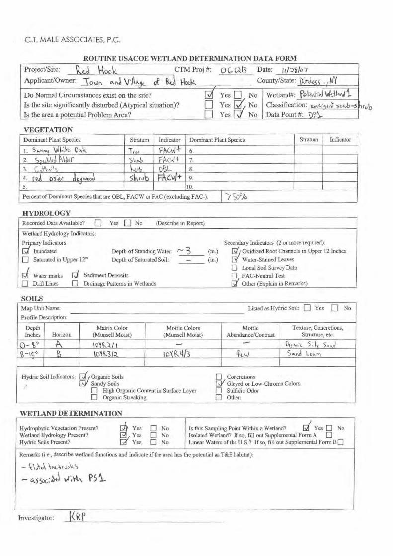
C.T. MALE ASSOCIATES, P.C.
ROUTINE USACOE WETLAND DETERMINATION DATA FORM
Project/Site:
it^o^4.
CTM Proj #: p C. c,JI3 Date:
^^/c7
Applicant/Owner:
"Tour.,
awl \i t,,
cst
4 County/State:
rat
5 , i
Do Normal Circumstances exist on the site?Is the site significantly disturbed (Atypical situation)?Is the area a potential Problem Area?
Yes q
Fl Yes ^NoNo
Wetland#: QaY n?
' ^nd
Classification: eMi-rle,i 5u-,.,b-5q Yes No Data Point #: pQ'^
VEGETATIONDominant Pl antSpecies Indicator Dominant Plant Species Stratum Indicator
'
`
(I-]
Sw4mt ^ Mh,k H .,K 1 re"-Ire"- VNC 14 6.``
2 .
S1itc,W kl4r S t r,b
_
FPC>^! 4 7.
3-
c1 ^ 1s LL O o^tr 8.t
`t4.
I4,d
o5,1wfi
^Ogwt,i)C
J.^ C ^Lr,^ e pP
F1^G 9.5. 10.
Percent of Dominant Species that are OBL, FACW or FAC (excluding FAC-). 50%
HYDROLOGYRecorded Data Available?
q Yes
[] No
(Describe in Report)
Wetland Hydrology Indicators:Indicators: Secondary Indicators (2 or more required):
Inundated Depth of Standing Water: r" 3 (in.) [^/, Oxidized Root Channels in Upper 12 InchesEl Saturated in Upper 12" Depth of Saturated Soil: (in.) L^ Water-Stained Leaves
[.J Water marks
[j Sediment Depositsq
Local Soil Survey Dataq
. FAC-Neutral Testq Drift Lines
q
Drainage Patterns in Wetlands Other (Explain in Remarks)
SOILSMap Unit Name: Listed as Hydric Soil: q Yes
q
NoProfile Description:
DepthInches Horizon
Matrix Color(Munsell Moist)
Mottle Colors(Munsell Moist)
MottleAbundance/Contrast
Texture, Concretions,Structure, etc.
I Grry^,.c
5'1),
5,,, j
S -k 5" k3Iz IoX
Llh +v.%) Sand
Loo,r,\
Hydric Soil Indicators: Organic Soils n
ConcretionsD/ Gleyed or Low-Chroma ColorsL^►' Sandy Soils
q
High Organic Content in Surface Layer n Sulfidic OdorOrganic Streaking q
Other:
WETLAND DETERMINATION
Is this Sampling Point Within a Wetland?
L.d Yes q NoIsolated Wetland? If so, fill out Supplemental Form A qLinear Waters of the U.S.? If so, fill out Supplemental Form B q
Remarks (i.e., describe wetland functions and indicate if the area has the potential as T&E habitat):
0,55ac.;
P51r
Hydrophytic Vegetation Present?Wetland Hydrology Present?Hydric Soils Present?
Yes q NoYes q NoYes q No
Investigator: KR?

C.T. MALE ASSOCIATES, P.C.
Jc
ROUTINE USACOE WETLAND DETERMINATION DATA FORM
Project/Site:
Hock
CTM Proj #: p c . c,13 Date:
Ml J. $/0 7
ApplicantlOwner:
To,Jn
Ani
Et
1-ictk County/State:
1) „1-61455 ,1,1't
Do Normal Circumstances exist on the site? Yes q No Wetland#: las h,
-a.^ -Is the site significantly disturbed (Atypical situation)? n Yes ! No Classification: e.,rr„^
Is the area a potential Problem Area? Yes vl No Data Point #: Q a
VEGETATIONDominant Plant Species Stratum Indicator Dominant Plant Species Stratum Indicator
1.
Sv,. ? \A
,
0,,k Tree, C^,(-^ 6.
2.
C .,c
^ . (s l r ^b pgL 7.
3-
Noldt f
^t1
.& 5 Fwh OBI- 8.1`
4-
Ce^ pa,c€
c^c,^kr a^L^ .54%rv6 El
,vJ+ 9.
5. 10.
Percent of Dominant Species that are OBL, FACW or FAC (excluding FAC-). > 5^ ° p
HYDROLOGYRecorded Data Available?
q Yes
q No
(Describe in Report)
Wetland Hydrology Indicators:
Primary Indicators: Secondary Indicators (2 or more required):a Inundated Depth of Standing Water: t" C (i id Oxidized Root Channels in Upper 12 Inchesq
Saturated in Upper 12" Depth of Saturated Soil: - (i
.) Water-Stained Leaves
DI Water marks
q Drift Lines
[I Sediment Deposits
Drainage Patterns in Wetlands
q Local Soil Survey DataFAC-Neutral TestOther (Explain in Remarks)
SOILSMap Unit Name: Listed as Hydric Soil: q Yes
q
No
Profile Description:
DepthInches Horizon
Matrix Color(Munsell Moist)
Mottle Colors(Munsell Moist)
MottleAbundance/Contrast
Texture, Concretions,Structure, etc.
' b 1'^ ^0\t,S
.11 ^- 7anJ
L0
OvXi l 1u
Q4,6L 'AI4 Lor^r.nlo 5 ,1ndr 5
Hydric Soil Indicators:[]^jOrganic Soils nQ
/ConcretionsSandy Soils Gleyed or Low-Chroma Colors
Sulfidic OdorOther:
n
High Organic Content in Surface Layer nq
Organic Streaking n
WETLAND DETERMINATION
Investigator:
^QLP
Hydrophytic Vegetation Present?
f Yes q NoWetland Hydrology Present?
Ht Yes q NoHydric Soils Present?
Yes q No
Is this Sampling Point Within a Wetland?
Yes q NoIsolated Wetland? If so, fill out Supplemental Form A q
Linear Waters of the U.S.? If so, fill out Supplemental Form B q
Remarks (i.e., describe wetland functions and indicate if the area has the potential as T&E habitat):
r ,
rtt. ^sur S
‘4 ;"N Psi
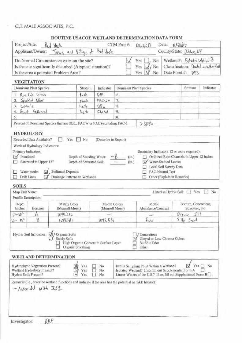
C.I. MALE ASSOCIATES, P.C.
ROUTINE USACOE WETLAND DETERMINATION DATA FORM
Project/Site:
CTMProj#: DC, C,,, 13 Date:
[If-?^^o7Applicant/Owner:
\N q{^
U;MI County/State: j),gei i k^^(
Do Normal Circumstances exist on the site? Yes //No Wetland#:
?o ;^f -ail 3
Is the site significantly disturbed (Atypical situation)?
q Yes ^JNo Classification: i ' loeieJ ^1r ti,+^1
Is the area a potential Problem Area? Yes No Data Point #:
p^3
VEGETATIONDominant Plant Species Stratum Indicator Dominant Plant Species Stratum Indicator
1.
cc Cuf
(7 r4g5 c r^i c B L 6.2.
SNkl
k\4.r Sh= F14Ctr1 4 7-3 .
_
k('b B 1- 8.
4.
G
al-
Gol^cot-J w^L f^ ft,C\,I 9.
5. ] 0.
Percent of Dominant Species that are 013L, FACW or FAC (excluding FAC-). 7 5QID
HYDROLOGYRecorded Data Available?
q
Yes
[] No (Describe in Report)
Wetland Hydrology Indicators:
Primary Indicators: Secondary Indicators (2 or more required):
[i Inundated
Depth of Standing Water:
r"g (in.) q
Oxidized Root Channels in Upper 12 Inches
q Saturated in Upper 12"
Depth of Saturated Soil:
--- (in.) E/ Water-Stained Leaves
q Water marks
2/ Sediment DepositsLocal Soil Survey DataFAC-Neutral Test
q Drift Lines
El/ Drainage Patterns in Wetlands Other (Explain in Remarks)
SOILSMap Unit Name: Listed as Hydric Soil: q Yes
q
No
Profile Description:
DepthInches Horizon
Matrix Color(Munsell Moist)
Mottle Colors(Munsell Moist)
Mottle
Abundance/ContrastTexture, Concretions,
Structure, etc.
O-` o" A to^R^la OrJs
S; If
lo~
;5' lO(4L413 lo^(R51A Caw
Hydric Soil Indicators: Organic Soils q
ConcretionsSandy Soils [
Gleyed or Low-Chroma Colorsn
High Organic Content in Surface Layer q
Sulfidic Odorq
Organic Streaking q Other:
WETLAND DETERMINATION
Hydrophytic Vegetation Present?Wetland Hydrology Present?Hydric Soils Present?
Yes q NoYes q NoYes q No
Is this Sampling Point Within a Wetland?
d Yes q NoIsolated Wetland? If so, fill out Supplemental Form A qLinear Waters of the U.S.? If so, fill out Supplemental Form B q
Remarks (i.e., describe wetland functions and indicate if the area has the potential as T&E habitat):
- A$soc,
w' z,51,
Investigator:
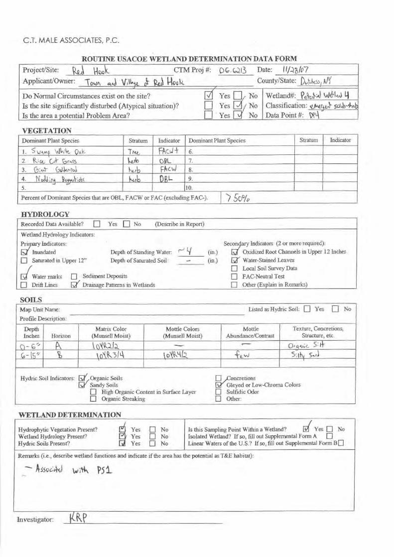
C.I. MALE ASSOCIATES, P.C.
ROUTINE USACOE WETLAND DETERMINATION DATA FORM
Proj ect/Site:
tZ,>z.d
^oQV_
CTM Proj #: p 6. cD13 Date:
I 1/4107
ApplicantlOwner:
-Towr,
ane \JL
oc
1-
k County/State:
p,,Yc}
! 1,J'(
Do Normal Circumstances exist on the site? I / Yes q No Wetland#: tnbb`l^t4 tiIs the site significantly disturbed (Atypical situation)? q Yes 3 / No Classification: ;„}- sal-44Is the area a potential Problem Area? n Yes No Data Point #: pQa r
VEGETATIONDominant Plant Species Stratum Indicator Dominant Plant Species Stratum Indicator
1.
S\ail)
\alk; lrt,
pug 7rct, FRC^,I-F 6.
2-
1K: a,
Gil`
raiS tsuk) O9L 7.
3.
(7:+^
(,91(nc l^ rb ptrC1nl 8.
4.
!`lori^in
^u
r^;cl ^v.r^ URL 9.
5. 10.
Percent of Dominant Species that are OBL, FACW or FAC (excluding FAC-). ) ,50%
HYDROLOGY
SOILSMap Unit Name: Listed as Hydric Soil: q Yes
q
No
Profile Description:
DepthInches Horizon
Matrix Color(Mansell Moist)
Mottle Colors(Mansell Moist)
MottleAbundance/Contrast
Texture, Concretions,Structure, etc.
MC^^ O r q'tn;C
5: !T
v
1' y
\{1 \931`\J
jjko%4 .z. 5',l}^
$ani
Hydric Soil Indicators: Di Organic Soils
q[Sandy Soils
,ConcretionsGleyed or Low-Chroma ColorsSulfidic OdorOther:
q
High Organic Content in Surface Layer qn
Organic Streaking El
WETLAND DETERMINATION
Recorded Data Available? q Yes [] No
(Describe in Report)
Wetland Hydrology Indicators:
Pn ary Indicators:
[Inundated
Depth of Standing Water:q Saturated in Upper 12" Depth of Saturated Soil:
Q Water marks q Sediment Deposits
q Drift Lines DI / Drainage Patterns in Wetlands
Sewn ary Indicators (2 or more required):
Oxidized Root Channels in Upper 12 Inches
[y' Water-Stained Leavesq Local Soil Survey Dataq FAC-Neutral Test
q Other (Explain in Remarks)
r^Lf
Hydrophytic Vegetation Present?Wetland Hydrology Present?Hydric Soils Present?
Yes q NoYes q NoYes q No
Is this Sampling Point Within a Wetland?
R( Yes q NoIsolated Wetland? If so, fill out Supplemental form A q
Linear Waters of the U.S.? If so, Iii)] out Supplemental Form BD
Remarks (i.e., describe wetland functions and indicate if the area has the potential as T&E habitat):
ASSo6 it u,;* P51
Investigator: 14- K. i
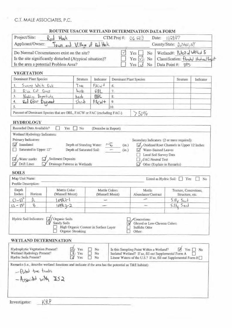
C.T. MALE ASSOCIATES, P.C.
ROUTINE USACOE WETLAND DETERMINATION DATA FORMProject/Site: ^oQk
CTMProj #: u(,fp213 Date:
r
Applicant/Owner:
awn '
*^;II.,
k County/State: II
h/Y
Do Normal Circumstances exist on the site?Is the site significantly disturbed (Atypical situation)?Is the area a potential Problem Area?
[q
n
YesYesYes
NoNoNo
Wetland#: Pe-;
Classification: fIoc ki ^vtlw
i t<
Data Point #:
pP5
VEGETATIONDominant Plant Species Stratum Indicator Dominant Plant Species Stratum Indicator
1.
S"aMQ W^;k
04k Trc^ F'Ac.^l t 6.
2.
R'u. OPL 7.3.
s
"It^ ,Ascl ' 8.
4.
ZIA Q$icr DaAwDe, S^.1 b FA,04+ 9.
5. 10.
Percent of Dominant Species that are OBL, FACW or FAC (excluding FAC-).
'7 5o%
HYDROLOGYRecorded Data Available?
q Yes
ill No
(Describe in Report)
Wetland Hydrology Indicators:
Primary Indicators: Secondary Indicators (2 or more required):Inundated Depth of Standing Water: f' (in.) [
Oxidized Root Channels in Upper 12 Inchesq
Saturated in Upper 12" Depth of Saturated Soil: (in.) [v^ Water-Stained Leaves
gi Water marks
Drift Lines
[i Sediment Deposits
[Drainage Patterns in Wetlands
q Local Soil Survey Data
Si/FAO-Neutral Test
Other (Explain in Remarks)
SOILSMap Unit Name: Listed as Hydric Soil: Yes
q
NoProfile Description:
DepthInches Horizon
Matrix Color(Munsell Moist)
Mottle Colors(Munsell Moist)
MottleAbundance/Contrast
Texture, Concretions,Structure, etc.
o-a' A v'tk.'Z-I
ki- OY^3 a - - 5,f .
5 4,,,l
Hydric Soil Indicators: Organic Soils n[^l Sandy Soils Q'
^CnncretionsGleyed or Low-Chroma ColorsSulfidic OdorOther:
q
High Organic Content in Surface Layer qOrganic Streaking q
WETLAND DETERMINATION
Hydrophytic Vegetation Present?
qJ Yes q NoWetland Hydrology Present?
[^ Yes q NoHydric Soils Present?
[^ Yes q No
Is this Sampling Point Within a Wetland?
4 Yes q NoIsolated Wetland? If so, fill out Supplemental Form A
qLinear Waters of the U.S.? If so, fill out Supplemental Form B q
Remarks (i.e., describe wetland functions and indicate if the area has the potential as T&E habitat):
'k ru, 4frv4,S
Investigator:

C.T. MALE ASSOCIATES, P.C.
ROUTINE USACOE WETLAND DETERMINATION DATA FORM
Project/Site:
k4.^
Pe
CTM Proj #: P 13 Date:
!i/.^o/07Applicant/Owner:
-T o,,, ,r.) v 11 o ha
n^
I-^oo1<County/State:
p„)rks5 ! WY
Do Normal Circumstances exist on the site?Is the site significantly disturbed (Atypical situation)?Is the area a potential Problem Area?
[nU
Yes IYesYes
1 No^I No3 No
Wetland#:
Qohr)',J 1,M'larA
Classification: e^f1t,
5^ ^5
Data Point #:
DQ
VEGETATIONDominant Plant Species Stratum Indicator Dominant Plant Species Stratum Indicator
].
5 wimp
1 Jln;k
0a(^ Tnrp. FAck.J 6.
2.
c;,o)'Jtt
&titr 54\ f t,b 't'cC1)+ 7.
3.
C,;•
Go14r\ rot, rb ^hC.J 8.
-
4.
Nodd n^
&rkA5 (^t t. ORL 9.
5. 10.
Percent of Dominant Species that are OBL, FACW or FAC (excluding FAC-). 5' po/'0
HYDROLOGY
SOILS
Map Unit Name: Listed as Hydric Soil: q Yes
q
No
Profile Description:
DepthInches Horizon
Matrix Color(Munsell Moist)
Mottle Colors(Munsell Moist)
MottleAbundance/Contrast
Texture, Concretions,Structure, etc.
Q-cz A xoyC-
11 - - Or^ ► ,
. S.l^
%-t5- lov1,31^ \o' 4/5 S,lty
►.^
Hydric Soil Indicators: Organic Soils nSandy Soils d Concretions
Gleyed or Low-Chroma ColorsSulfidic OdorOther:
n
High Organic Content in Surface Layer nn
Organic Streaking q
WETLAND DETERMINATION
Recorded Data Available? q Yes q No
(Describe in Report)
Wetland Hydrology Indicators:
Primary Indicators:
"Inundated
Depth of Standing Water:
q Saturated in Upper 12" Depth of Saturated Soil:
q, / Sediment Deposits
Drainage Patterns in Wetlands
Secondary Indicators (2 or more required):
q Oxidized Root Channels in Upper 12 Inches
Water-Stained Leaves[11 Local Soil Survey Dataq FAC-Neutral Test[/ Other (Explain in Remarks)
a
[I Water marks
q Drift Lines
Hydrophytic Vegetation Present?
Ei Yes q NoWetland Hydrology Present?
L Yes q NoHydric Soils Present?
Yes q No
Is this Sampling Point Within a Wetland?
[( Yes q NoIsolated Wetland? If so, fill out Supplemental Form A qLinear Waters of the U.S.? If so, fill out Supplemental Form B q
Remarks (i.e., describe wetland functions and indicate if the area has the potential as T&E habitat):
- ^1W -VA ^funtiL^
^ssoe_, O vi ;SA, I's a
Investigator: kR P

C.T. MALE ASSOCIATES, P.C.
ROUTINE USACOE WETLAND DETERMINATION DATA FORM
Project/Site:
VA ttC`c^`
CTM Proj #: 06-CZ 13 Date:
/-?6 /P7
Applicant/Owner:
-Novo
ar,tl v \1a 4Q
Hoo1t County/State:
P 11'(
Do Normal Circumstances exist on the site?Is the site significantly disturbed (Atypical situation)?Is the area a potential Problem Area?
Yes q NoNoNo
Wetland#:
Qo1
^V t^le`^l^,,l'7
q Yesq Yes
Classification: {ice 4yn^cl}^,I.^EData Point #:
^Q l
VEGETATIONDominant Plant Species Stratum Indicator Dominant Plant Species Stratum Indicator
1.
R : Ce.
^ -
Gr"55 krb. 6.
2.
S^.ckka
P&r 4>4 I+ 7.
3.
CA^^1*s ^e r (RA- 8.
4.
G
Got
e Pcc 9.
5. 10.
Percent of Dominant Species that are OBL, FACW or FAC (excluding FAC-). ' Solo
HYDROLOGYRecorded Data Available?
E]
Yes
q No
(Describe in Report)
Wetland Hydrology Indicators:
Pri ary Indicators: Secondary Indicators (2 or more required):
[Inundated Depth of Standing Water: rv` Q (in.) q
, Oxidized Root Channels in Upper 12 Inches
q Saturated in Upper 12" Depth of Saturated Soil: (in.) Water-Stained Leaves
[IWater marks
q Sediment DepositsLocal Soil Survey DataFAC-Neutral Test
q
Drift Lines Drainage Patterns in Wetlands Other (Explain in Remarks)
SOILSMap Unit Name: Listed as Hydric Soil: q Yes
q
No
Profile Description:
DepthInches Horizon
Matrix Color(Munsell Moist)
Mottle Colors(Munsell Moist)
MottleAbundance/Contrast
Texture, Concretions,Structure, etc.
P'c to .'car J Orrf.
"
k5 % 0`^^3l2 10,R'1/5 f^vJ Saocl
1-owr,
Hydric Soil Indicators: Organic Soils qLy Sandy Soils [v^
ConcretionsGleyed or Low-Chroma ColorsSulfidic OdorOther:
q
High Organic Content in Surface Layer nn
Organic Streaking n
WETLAND DETERMINATION
Hydrophytic Vegetation Present?Wetland Hydrology Present?Hydric Soils Present?
Yes q NoYes q NoYes q No
Is this Sampling Point Within a Wetland?
d Yes q NoIsolated Wetland? If so, fill out Supplemental Form A
qLinear Waters of the U.S.? If so, fill out Supplemental Form B q
Remarks (i.e., describe wetland functions and indicate if the area has the potential as T&E habitat):
-- ky3vc, `
P5
Investigator: KR P

C.T. MALE ASSOCIATES, P.C.
ROUTINE USACOE WETLAND DETERIHNATION DATA FORM
Project/Site:
‘<.,l ^g Q
CTM Proj #: 13 Date:
/ (/ i/Q7
Applicant/Owner:
700,
.‘..,r,,\
0C
k) County/State:
0„,losIt /
Do Normal Circumstances exist on the site? Yes q No Wetland#: a i U s J
Is the site significantly disturbed (Atypical situation)? Yes No Classification: fbEdl;
Is the area a potential Problem Area? - q Yes No Data Point #: pe%
VEGETATIONDominant Plant Species Stratum Indicator Dominant Plant Species Stratum Indicator
1.
5
c.1<1-e 5k O'c c t+ 6.
2.
C^1^als h^r^ O^L 7.
3.
U ; &A
ro,\y F Pty .4 8.
4.
NoA'NB J, : 4,t.k OK- 9.
5. 10.
Percent of Dominant Species that are OBL, FACW or FAC (excluding FAC-). ) ^D gfp
HYDROLOGYRecorded - Data Available?
q
Yes
q No
(Describe in Report)
Wetland Hydrology Indicators:
Pn Indicators: Secon
Indicators (2 or more required):Inundated Depth of Standing Water: (tn.) Oxidized Root Channels in Upper 12 Inches
q Saturated in Upper 12"
Depth of Saturated Soil: (in.) Water-Stained Leaves
a Water marks q
Sediment Depositsq
/ Local Soil Survey DataFAC-Neutral Test
q
Drift Lines [^ Drainage Patterns in Wetlands Other (Explain in Remarks)
SOILSMap Unit Name: Listed as Hydric Soil: q Yes
q
No
Profile Description:
DepthInches Horizon
Matrix Color(Mun selllMoist)
Mottle Colors(Munsell Moist)
MottleAbundance/Contrast
Texture, Concretions,Structure, etc.
pp
-15J' g t o'k Q,3iq oNkM15 5 -.p-,Ill Loa, in
Hydric Soil Indicators: Organic Soils qSandy Soils
ConcretionsGleyed or Low-Chroma Colors
q
High Organic Content in Surface Layer n Sulfidic Odorq
Organic Streaking n Other:
WETLAND DETERMINATION
Hydrophytic Vegetation Present?Wetland Hydrology Present?Hydric Soils Present?
Yes q NoYes q NoYes q No
Is this Sampling Point Within a Wetland?
[
Yes q NoIsolated Wetland? If so, fill out Supplemental Form A
qLinear Waters of the U.S.? If so, fill out Supplemental Form B q
Remarks (i.e., describe wetland functions and indicate if the area has the potential as T&E habitat):
a3504 , 4e) yr :Fh Q5
Investigator:
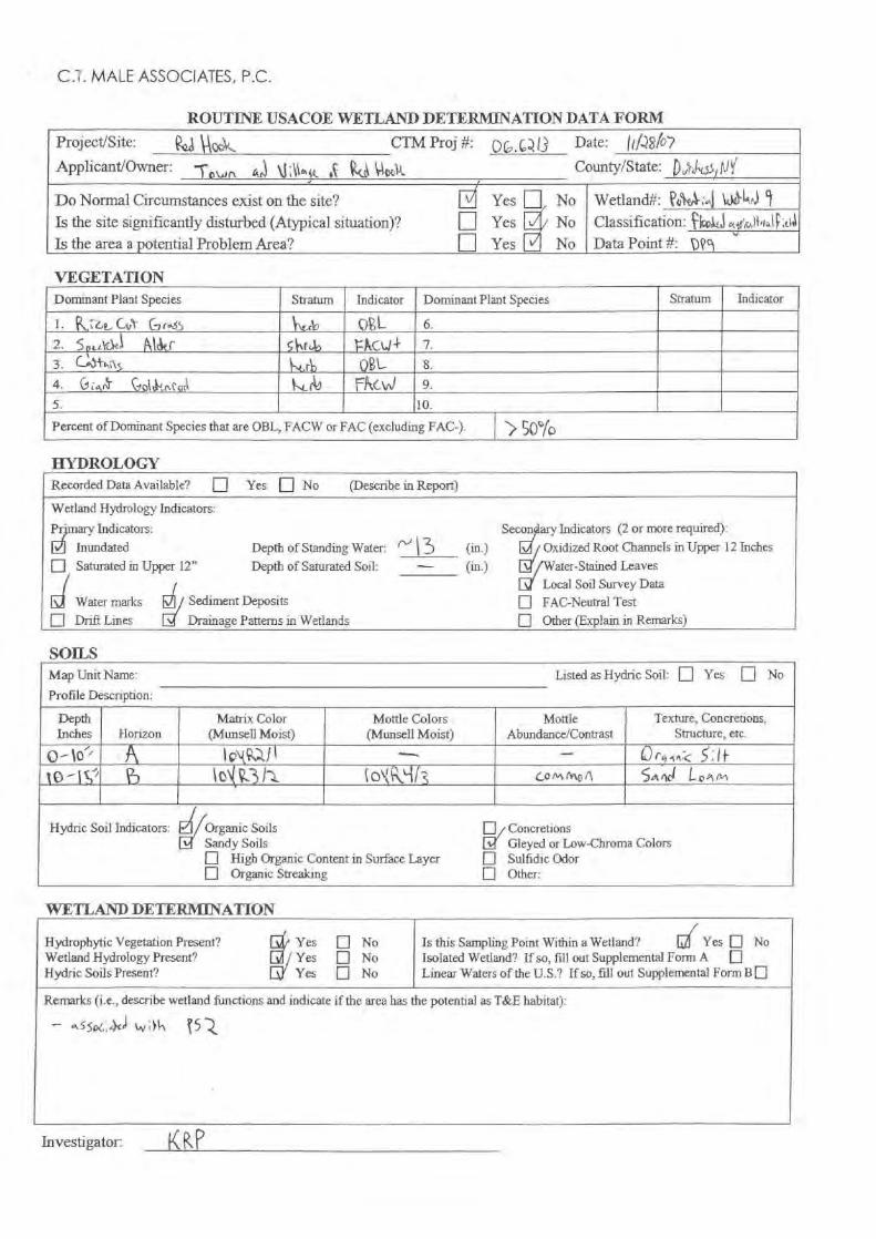
C.-1. MALE ASSOCIATES, P.C.
MROUTINE USACOE WETLAND DETERMINATION DATA FORM
Project/Site:
[
^C 4
CTM Proj #: p^ ^^f3 Date:
Applicant/Owner:
-rowt^
Wic County/State: [) U5,r rtl
Do Normal Circumstances exist on the site?Is the site significantly disturbed (Atypical situation)?Is the area a potential Problem Area?
7(Yes n//.
NoNoNo
Wetland#: ^o ;^j 4, A!) 1q Yes / Classification:
Data Point #:,
^;ir`,,If,r^,lf ;ci
n Yest
'M
VEGETATIONDominant Plant Species Stratum Indicator Dominant Plant Species Stratum Indicator
CO-1.
G r^55 rS O L 6.
2.
5o L\
.1
R1&r sbr^, P C,t,r+ ^-3.
C^Sth;lg \^.rl) Q L 8.
4.
G
Q1olc (,ru,. 4.t r^J Ff\C^J 9.5. 10.
Percent of Dominant Species that are OBL, FACW or FAC (excluding FAC-).
) 50°rD
HYDROLOGY
SOILSMap Unit Name: Listed as Hydric Soil: q Yes
q
NoProfile Description:
DepthInches Horizon
Matrix Color(Mansell Moist)
Mottle Colors(Mansell Moist)
MottleAbundance/Contrast
`texture, Concretions,Structure, etc.
10 - c,' o1(R^.3 <1 O^ yl s G9nn rot;fi Se.lcd
Hydric Soil Indicators: E
Organic Soils q ConcretionsSandy Soils Gleyed or Low-Chroma Colorsq
High Organic Content in Surface Layer q Sulfidic Odorq
Organic Streaking n Other:
WETLAND DETERMINATION
Recorded Data Available? q Yes q No
(Describe in Report)
Wetland Hydrology Indicators:
Pmany Indicators:q Inundated Depth of Standing Water:q Saturated in Upper 12" Depth of Saturated Soil:
Water marks
Sediment Depositsq Drift Lines d Drainage Patterns in Wetlands
Secon ary Indicators (2 or more required):(in.)
Oxidized Root Channels in Upper 12 Inches(in.)
/Water-Stained LeavesLocal Soil Survey Data
q FAC-Neutral Testq Other (Explain in Remarks)
NI3
Is this Sampling Point Within a Wetland?
d Yes q NoIsolated Wetland? If so, fill out Supplemental Form A
qLinear Waters of the U.S.? If so, fill out Supplemental Form B q
Remarks (i.e., describe wetland functions and indicate if the area has the potential as T&E habitat):
asso,,,.a wtlh
5
Hydrophytic Vegetation Present?Wetland Hydrology Present?Hydric Soils Present?
Yes q NoYes q NoYes q No
Investigator: KM)

C.T. MALE ASSOCIATES, P.C.
Mr. Ganj MaleDecember 5, 2007Page -3-
Attachment DField Sketch Maps
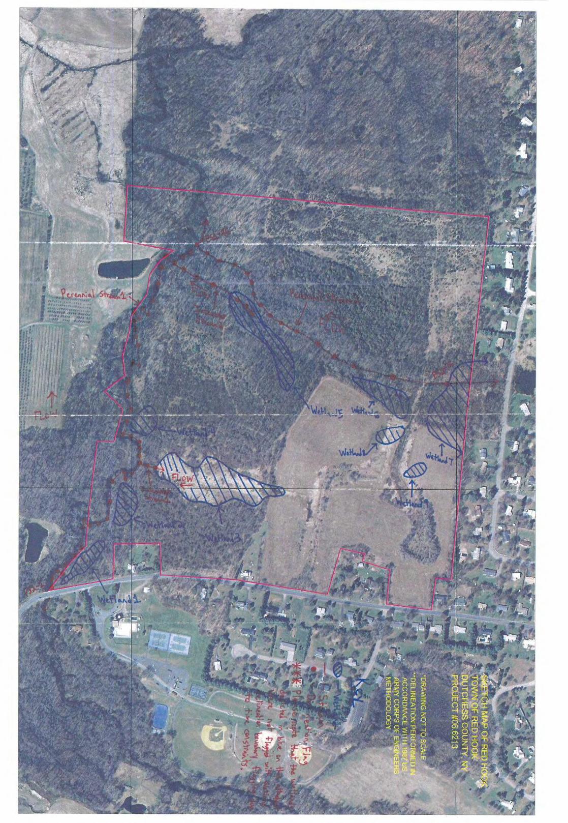
e.rernniGI#6fi; Y O',r:rlr v.ri+ a , a..vr r+T,/ut
., 1 r. +.tit //1rNr3 r/lr1.l.r lr
r^A^I,dri. A/,/
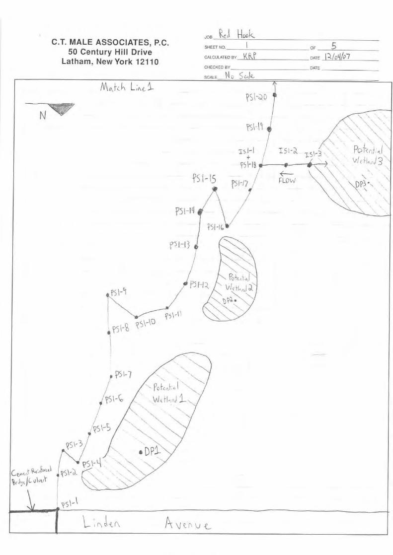
C.T. MALE ASSOCIATES, P.C.50 Century Hill Drive
Latham, New York 12110
N\ i L;m,
---NT‘Tqr
JOB LI NookSHEET NO.
p
OF 5J^Jr
CALCULATED BY`I R CATE (I^IO4/^
CHECKED BY DATE
SCALE SCult,
' 1 C,ta- l,SS A " !^,
QSI°19
f5i"J?
FLOW
i
ISt'3 `,
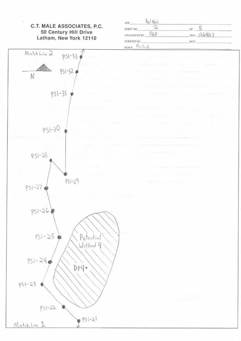
C.T. MALE ASSOCIATES, P.C.50 Century Hill Drive
Latham, New York 12110
JOB k^ Hoo'k
SHEET NO,t^Q
OF SCALCULATED BY DATE ,10 10CHECKED BY DATE
SCALE
;L
Mu,.*ch L;Ae. a
f 5
3
N
PS^-3), 71
Pal-3
P5I-Z9
PS - a^Dv4.
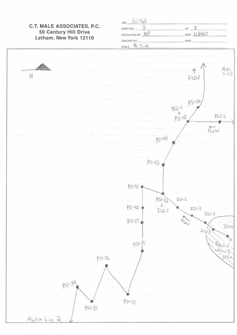
JOB EeWi-!"C ,
5SHEET NO, OF 5
CALCULATED BY KkGl DATE /Q4107
CHECKED BY DATE
SCALE`(
C.T. MALE ASSOCIATES, P.C.50 Century Hill Drive
Latham, New York 12110
L:rk-3
^ 5\ ..L 5
Psa a
FLo 1
F51-43 4
P5H f
t\ \ co-6k
p5l-.l

C.T. MALE ASSOCIATES, P.C.50 Century Hill Drive
Latham, New York 12110
JOB
SHEET NO. Li OF 5CALCULATED BY DATE
CHECKED BY
I,,
DATE
SCALE (J k.
N
14.1+chL;AE
'6k-3
5:-15

JoBvSHEET NO. 5 CE
CALCULATED BY DATE 4 .-_ f.:,'`ID !
CHECKED BY DATE
SCALE f- ri
C.T. MALE ASSOCIATES, P.C.50 Century Hill Drive
Latham, New York 12110