basics of sensors overview of smart sensor description of
TRANSCRIPT


Basics of sensors Overview of Smart Sensor Description of the architecture of a smart sensor Operation Evolution of smart sensors Applications
Tuesday, 28 March 2017Sukanta Bhattacharyya 2

A sensor is basically an element that produces a signalrelating to the quantity to be measured. For example letus consider an electrical resistance temperature element.Here the measurand is the temperature which is beingsensed by the said device and it produces an electricalresistance from the temperature being measured.
Tuesday, 28 March 2017Sukanta Bhattacharyya 3

Static Characteristics:• Accuracy• Precision• Reproducibility & Repeatability• Range and span• Sensitivity• Signal to noise(S/N) ratio• Linearity• Hysteresis
Tuesday, 28 March 2017Sukanta Bhattacharyya 4

Dynamic Characteristics:• Frequency and Impulse responses• Speed of the response• Measuring lag• Fidelity• Dynamic error
Tuesday, 28 March 2017Sukanta Bhattacharyya 5

Sensor Types Examples
Flow Differential Pressure, Electromagnetic, Ultrasonic
Level Mechanical, DP, Magnetostrictive, radio frequency
Temperature RTD, Thermistor, Thermocouple,
Displacement Potentiometric, LVDT, Capacitive, Photoelectric
Acceleration Accelerometer, Gyroscope
Image CMOS,CCDs
Chemical Ionization, Infrared, Semiconductor
Biosensor Electrochemical, SPR,LAP
Others Mass, Force, Humidity, Viscosity
Tuesday, 28 March 2017Sukanta Bhattacharyya 6
A sensor producing an electrical output, when combinedwith some interfacing hardwares is termed to be anintelligent sensor. Intelligent sensors are also calledsmart sensors, which is a more acceptable term now.
Sensors + Interfacing hardwares=Smart sensors
This type of sensor is different from other type of sensorsas because it carries out functions like ranging,calibration and decision making for communications andutilization of data.
Tuesday, 28 March 2017Sukanta Bhattacharyya 7

Smart Sensor
NormalSensorssuch aspressuretemperatureInterfacing hardwares
Tuesday, 28 March 2017Sukanta Bhattacharyya 8

Tuesday, 28 March 2017Sukanta Bhattacharyya 9
Smart Sensor
Sensor
Communication interface
Memory device
DAS module

Tuesday, 28 March 2017Sukanta Bhattacharyya 10
Smart Sensor

Automatic ranging and calibration of data through abuilt in system.
Automatic DAS and storage of calibration constants inlocal memory of the field device.
Automatic linearization of nonlinear transfer functions. Auto-correction of offsets, time and temperature drifts. Self tuning control algorithms. Control is implementable through signal bus and a host
system. Initiates communication through serial bus.
Tuesday, 28 March 2017Sukanta Bhattacharyya 11
Tuesday, 28 March 2017Sukanta Bhattacharyya 12
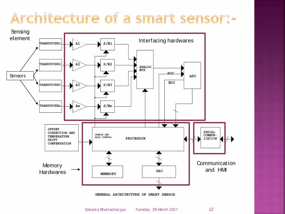
Sensors
Interfacing hardwares
Sensing element
Communication and HMI
Memory Hardwares
The general architecture of a smart sensor has thefollowing components namely Sensing element and transduction element. Interfacing Hardwares/Data Acquisition System (DAS)
Signal Conditioning Devices.Conversion Devices.
Programming Devices. Communication Interfaces.
Tuesday, 28 March 2017Sukanta Bhattacharyya 13

Description of the components
Sensing element and Transduction element:
It is the first component of the sensor system that comes incontact with the measurand. The measurand can be anyform like pressure,flow,level, temperature etc.
This element is also termed as the primary sensing elementof a measurement system.
Tuesday, 28 March 2017Sukanta Bhattacharyya 14

Data Acquisition System ( DAS):A DAS is used for the measurement and processing of aninput response or any measurand before it is beingdisplayed on the operator desk or permanently recordedand monitored. Following are the components toaccomplish the necessary tasks.
Transducers. Signal Conditioning and Signal Processing Unit. Conversion elements like ADC/DAC. Multiplexer and Demultiplexer.
Tuesday, 28 March 2017Sukanta Bhattacharyya 15

Transducers:
A transducer in general is adevice that converts one formof energy to another form.Transducers change thephysical phenomena intoelectrical signals.
A common example is RTD thatconverts the temperature intocorresponding electrical signalthat is measured in termsof voltage or resistance.
Tuesday, 28 March 2017Sukanta Bhattacharyya 16
Resistance Temperature Detector

Signal Conditioning and Signal Processing Unit:The process of manipulating and modifying the inputsignal or measurand in such a way that it meets thenecessary requirements for further processing. Signalconditioning of an input signal is done through thefollowing steps Amplification Filtering Linearization Sampling Modulation Excitation
Tuesday, 28 March 2017Sukanta Bhattacharyya 17
Amplification: Process of boosting up the input signalfor the purpose of increasing the resolution and reducingthe noise.Filtering: Extended process of amplification stage toremove the unwanted noise components present in thesignal of interest. The noise components can be removedusing LPF and HPF depending on the input signal.Linearization: Process of converting a non linear responseinto a linear one for better output response.Sampling: Process of conversion of a continuous signalinto a discrete signal.Modulation: Transmitting the input signal carrying usefulinformation to a remote site appended with a carrier signaldepending on the channel bandwidth and frequency.
Tuesday, 28 March 2017Sukanta Bhattacharyya 18
Excitation: Signal conditioning also generates excitationfor some passive transducers such as strain gauge, RTDwhich acquire external voltages for their operation.RTDmeasurements are usually made with a current excitationsource that converts the change in resistance into ameasurable voltage.
Tuesday, 28 March 2017Sukanta Bhattacharyya 19

ADC and DAC converters:
The data converters convert one form of data into anotherform. There are two types of data converters
Analog to Digital Converter(ADC)Digital to Analog Converter(DAC)
Tuesday, 28 March 2017Sukanta Bhattacharyya 20

Tuesday, 28 March 2017Sukanta Bhattacharyya 21
Analog to Digital Converter (ADC):An analog-to-digital converter is a device that converts acontinuous physical quantity (usually voltage) to a digitalnumber that represents the quantity's amplitude.The conversion is done through 3 stepsSamplingQuantizationCoding
Digital to Analog Converter (DAC):A device that converts a digitised input signal into itscontinuous analog output signal(current, voltage or electriccharge).

Tuesday, 28 March 2017Sukanta Bhattacharyya 22
Data conversion and sample data system

Sample and Hold Circuit (S/H):
Sample and hold circuit is an analog device that samplesthe voltage of a continuously varying analog signal andholds its value at a constant level for a specified minimalperiod of time.They are typically used in analog-to-digital converters toeliminate variations in input signal that can corrupt theconversion process.
Tuesday, 28 March 2017Sukanta Bhattacharyya 23

Tuesday, 28 March 2017Sukanta Bhattacharyya 24
Fig: Sample and Hold circuit: AI=Analog Input, AO=Analog Output C=control signal
The sample and hold circuit stores electric charge in a capacitor andcontains a switch and at least one operational amplifier. To sample theinput signal the switch connects the capacitor to the output of a bufferamplifier. The buffer amplifier charges or discharges the capacitor sothat the voltage across the capacitor is practically equal, orproportional to, input voltage. In hold mode the switch disconnects thecapacitor from the buffer. The capacitor is invariably discharged by itsown leakage currents and useful load currents.

Multiplexer( MUX):is a device that selects one ofseveral analog or digital inputsignals and forwards theselected input into a single line.A multiplexer of 2n inputshas n select lines, which areused to select which input line tosend to the output.
Demultiplexer(DEMUX):is a device that producesmultiple number of outputs froma single input. A demultiplexerwith a single input and 2n
outputs has n select lines.
Tuesday, 28 March 2017Sukanta Bhattacharyya 25
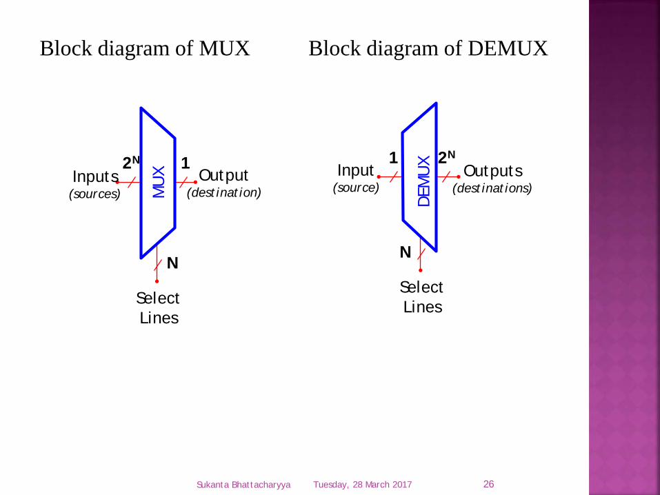
Block diagram of MUX Block diagram of DEMUX
Tuesday, 28 March 2017Sukanta Bhattacharyya 26
SelectLines
Input(source)
Outputs(destinations)
2N1
N
DEM
UX
SelectLines
Inputs(sources)
Output(destination)
12N
N
MU
X
Programming Devices:
After the data acquisition process is over, the processedsignal is fed into the programming devices such asmicroprocessor for the purpose of programming andstorage of the programmed data in the memory devices.
Tuesday, 28 March 2017Sukanta Bhattacharyya 27

Microprocessor (8085)-a brief introduction:
A microprocessor is a multipurpose, programmable,clock driven register based electronic device that readsbinary instructions from a storage device called memory,accepts binary data as input and processes data accordingto those instructions and provides results as output.
Tuesday, 28 March 2017Sukanta Bhattacharyya 28

Tuesday, 28 March 2017Sukanta Bhattacharyya 29
Architecture of 8085 microprocessor

Communication interfaces:
The programmed output of the microprocessor which isdigital in nature in now finally fed to the computing devicesuch as computers for the final processing, recording anddisplaying. The communication of the processed andprogrammed data from the data acquisition unit to thecomputer is initiated by using a RS-232 fastcommunication interface.
Tuesday, 28 March 2017Sukanta Bhattacharyya 30

Tuesday, 28 March 2017Sukanta Bhattacharyya 31
RS-232 communication interface

In the architecture shown A1, A2…An and S/H1,S/H2…S/Hn are the amplifiers and sample and holdcircuit corresponding to different sensing elementrespectively. So as to get a digital form of an analogsignal the analog signal is periodically sampled (itsinstantaneous value is acquired by circuit), and thatconstant value is held and is converted into a digitalwords. Any type of ADC must contain or proceeded by, acircuit that holds the voltage at the input to the ADCconverter constant during the entire conversion time.
Tuesday, 28 March 2017Sukanta Bhattacharyya 32

Conversion times vary widely, from nanoseconds (forflash ADCs) to microseconds (successive approximationADC) to hundreds of microseconds (for dual slopeintegrator ADCs).ADC starts conversion when it receivesstart of conversion signal (SOC) from the processor andafter conversion is over it gives end of conversion signalto the processor. Outputs of all the sample and holdcircuits are multiplexed together so that we can use asingle ADC, which will reduce the cost of the chip.Offset compensation and correction comprises of anADC for measuring a reference voltage and other for thezero. Dedicating two channels of the multiplexer andusing only one ADC for whole system can avoid theaddition of ADC for this. This is helpful in offsetcorrection and zero compensation of gain due totemperature drifts of acquisition chain.
Tuesday, 28 March 2017Sukanta Bhattacharyya 33

Tuesday, 28 March 2017Sukanta Bhattacharyya 34
Operation of smart sensor
Inputs
Output
First generation devices had little, if any electronicsassociated with them.
Second generation sensors were part of purelyanalog systems with virtually all of the electronicsremote from the sensor.
Tuesday, 28 March 2017Sukanta Bhattacharyya 35

Third generation smart sensor
Tuesday, 28 March 2017Sukanta Bhattacharyya 36

Fourth generation smart sensor
Tuesday, 28 March 2017Sukanta Bhattacharyya 37

Fifth generation smart sensor
Tuesday, 28 March 2017Sukanta Bhattacharyya 38
General Applications Industrial Applications Medical Applications
Tuesday, 28 March 2017Sukanta Bhattacharyya 39

General Applications:Smart sensor enhances the following applications:
o Self calibration: Adjust deviation of o/p of sensor fromdesired value.
o Communication: Broadcast information about its ownstatus.
o Computation: Allows one to obtain the average,variance and standard deviation for the set ofmeasurements.
o Multisensing: A single smart sensor can measurepressure, temperature, humidity, gas flow and infrared,chemical reaction surface acoustic vapour etc.
Tuesday, 28 March 2017Sukanta Bhattacharyya 40

Industrial Applications:
Accelerometer Optical Sensor Infra red detector Structural Monitoring Geological Mapping
Tuesday, 28 March 2017Sukanta Bhattacharyya 41

It consists of the sensingelement and electronics onsilicon. The accelerometeritself is a metal-coated SiO2cantilever beam that isfabricated on silicon chipwhere the capacitance betweenthe beam and the substrateprovides the output signal.
Tuesday, 28 March 2017Sukanta Bhattacharyya 42
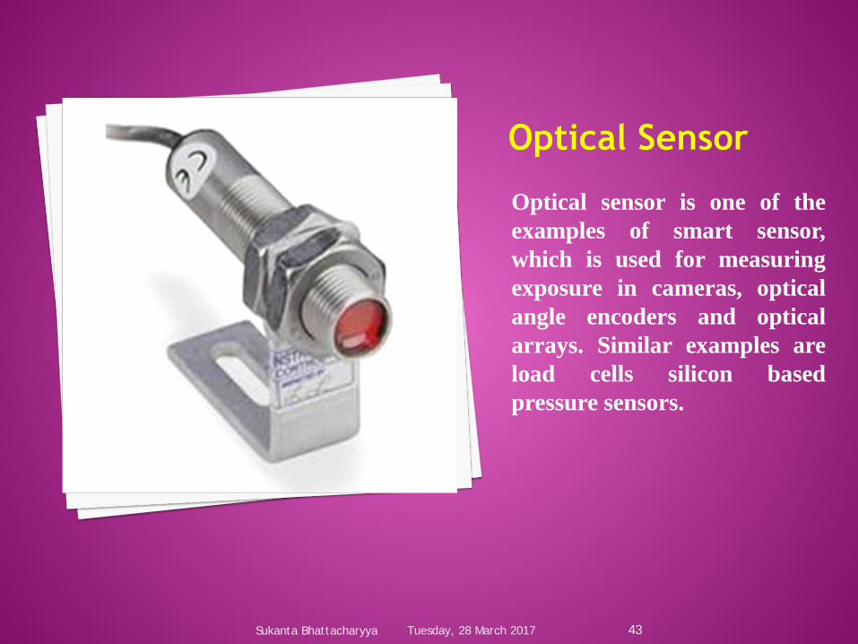
Optical sensor is one of theexamples of smart sensor,which is used for measuringexposure in cameras, opticalangle encoders and opticalarrays. Similar examples areload cells silicon basedpressure sensors.
Tuesday, 28 March 2017Sukanta Bhattacharyya 43

It is developed at solidlaboratory of university ofMichigan. Here infraredsensing element is developedusing polysilicon.
Tuesday, 28 March 2017Sukanta Bhattacharyya 44
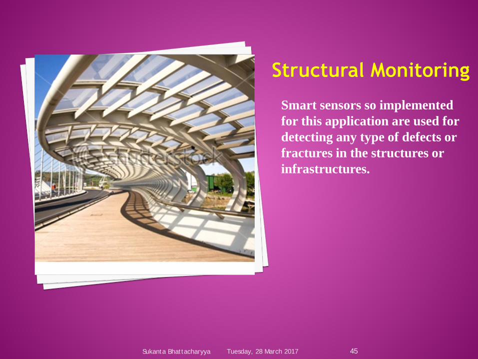
Smart sensors so implemented for this application are used for detecting any type of defects or fractures in the structures or infrastructures.
Tuesday, 28 March 2017Sukanta Bhattacharyya 45

It is needed mainly to detect the minerals on the geological areas.
Digital imaging & interpretation of tunnel geology.
Remote measurements of tunnel response.
Tuesday, 28 March 2017Sukanta Bhattacharyya 46

Medical Applications:
Food safety Biological hazard detection Safety hazard detection and warning Environmental monitoring both locally and globally Health monitoring Medical diagnostics
Tuesday, 28 March 2017Sukanta Bhattacharyya 47

A sensor is an element that produces a signal relating to the quantityto be measured.Sensors + Interfacing hardwares=Smart sensors.Architecture of a smart sensor consists of sensing element, DAS,programming and necessary network peripherals.Operation is through sensing, signal conditioning and signalprocessing, programming , storage, communication and displaying.Smart sensor technology is widely used in industrial and medicalapplications.
Tuesday, 28 March 2017Sukanta Bhattacharyya 48

• ‘Sensors and Transducers’ by D.Patranabis• Google-www.google.com• Wikipedia-www.wikipedia.org• Google images
Tuesday, 28 March 2017Sukanta Bhattacharyya 49