basic switching
DESCRIPTION
basicTRANSCRIPT

CCNP - CCIP
www.id-networkers.com

Course Breakup
Frame-Relay & RIPv2 EIGRP, OSPF, Route Filtering & Redistribution OSPF & BGP MPLS & MPLS - VPN Advanced Switching & Security IOS Services & QOS Multicasting & IPv6 100 Point Super Lab
www.id-networkers.com2

BASIC SWITCHINGSection 2
www.id-networkers.com3

Basic Switching
Contents Simulating a logical topology with the physical topology VLAN VLAN Trunking VTP STP Ether-channel
www.id-networkers.com4

Basic Switching
Virtual LANs (VLANs) Virtual networking refers to the ability of switches and routers to
configure logical topologies on top of the physical network infrastructure
Virtual LANs (VLANs) offer significant benefits in terms of efficient use of bandwidth, flexibility, performance, and security
VLAN technology functions by logically segmenting the network into different broadcast domains so that packets are only switched between ports that are designated for the same VLAN
www.id-networkers.com5

Basic Switching
Trunking Overview A trunk is a point-to-point link between one or more Ethernet switch
interfaces and another networking device such as a router or a switch. Trunks carry the traffic of multiple VLANs over a single link.
Trunking encapsulations available on all Ethernet interfaces: Inter-Switch Link (ISL)-ISL is Cisco-proprietary trunking encapsulation. 802.1Q—802.1Q is industry-standard trunking encapsulation.
www.id-networkers.com6

Basic Switching
Default behavior of Switches Both 3550 and 3560 are L3 switches, i.e. with basic L2 switching
functionality and L3 routing functionality All interfaces by default are
3550 – Dynamic desirable 3560 – Dynamic auto
www.id-networkers.com7

Basic Switching
Native VLAN If a packet is received on a dot1q link, that does not have VLAN
tagged, it is assumed that it belongs to native VLAN If we change the native VLAN, then it has to match on both the
links Mismatch native VLANs can result in STP loops
www.id-networkers.com8

Basic Switching
Understanding VTP VTP is a Layer 2 protocol that maintains VLAN configuration
consistency by managing the addition, deletion, and renaming of VLANs on a network-wide basis
VTP minimizes misconfigurations and configuration inconsistencies that can cause several problems, such as duplicate VLAN names, incorrect VLAN-type specifications, and security violations
Before you create VLANs, you must decide whether to use VLAN Trunking Protocol (VTP) to maintain global VLAN configuration for your network
www.id-networkers.com9

Basic Switching
Understanding VTP (Cont’d) There are three different modes of VTP
Server Client Transparent
VTP works only on trunk links.
www.id-networkers.com10
Basic Switching
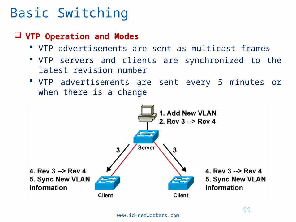
VTP Operation and Modes VTP advertisements are sent as multicast frames VTP servers and clients are synchronized to the latest revision
number VTP advertisements are sent every 5 minutes or when there is a
change
www.id-networkers.com11

Basic Switching
VTP Pruning Increases available bandwidth by reducing unnecessary flooded
traffic Example: Station A sends broadcast, and broadcast is flooded
only toward any switch with ports assigned to the red VLAN
www.id-networkers.com12

Basic Switching
Version-dependant Transparent-mode VTP Version 2 supports token ring. In VTP Version 1, a VTP transparent switch inspects VTP
messages for the domain name and version and forwards message only if the version and domain name matches.
In VTP Version 2, a VTP transparent switch will not inspect VTP messages and forwards even it doesn’t match.
www.id-networkers.com13

Basic Switching
Ether Channel Used to aggregate bandwidth between multiple L2 / L3 interfaces “channel-group” command under the interface Port-channel is the logical instance of the physical interfaces The two Ether-channel protocols
PAgP (Port Aggregation Protocol) LACP (Link Aggregation Control Protocol)
www.id-networkers.com14

Basic Switching
Successful combination of etherchannel would be: On – On Desirable – Desirable Desirable – Auto Active – Active Active – Passive
www.id-networkers.com15
Mode Result
On PAgP and LACP disabled (negotiation disable)
Auto Passively listen for PAgP
Desirable Actively negotiate PAgP
Passive Passively listen for LACP
Active Actively negotiate LACP

Basic Switching
EtherChannel Modes active Places an interface into an active negotiating state, in
which the interface starts negotiations with other interfaces by sending LACP packets
auto Places an interface into a passive negotiating state, in which the interface responds to PAgP packets it receives but does not start PAgP packet negotiation. This setting minimizes the transmission of PAgP packets
desirable Places an interface into an active negotiating state, in which the interface starts negotiations with other interfaces by sending PAgP packets
www.id-networkers.com16

Basic Switching
EtherChannel Modes on Forces the interface into an EtherChannel without PAgP or
LACP. With the on mode, a usable EtherChannel exists only when an interface group in the on mode is connected to another interface group in the on mode
passive Places an interface into a passive negotiating state, in which the interface responds to LACP packets that it receives, but does not start LACP packet negotiation. This setting minimizes the transmission of LACP packets
www.id-networkers.com17

Basic Switching
Layer 2 EtherChannels This example shows how to assign Gigabit Ethernet interfaces 0/4
and 0/5 as static-access ports in VLAN 10 to channel 5 with the PAgP mode desirable:
www.id-networkers.com18
Switch# configure terminal Switch(config)# interface range gigabitethernet0/4 -5 Switch(config-if-range)# switchport mode access Switch(config-if-range)# switchport access vlan 10 Switch(config-if-range)# channel-group 5 mode desirable

Basic Switching
Layer 3 EtherChannel
www.id-networkers.com19
Step1:-Switch# configure terminal Switch(config)# interface port-channel 5 Switch(config-if)# no switchport Switch(config-if)# ip address 172.10.20.10 255.255.255.0
Step2:-Switch(config)# interface range gigabitethernet0/1 -2 Switch(config-if-range)# no ip address Switch(config-if-range)# no switchport Switch(config-if-range)# channel-group 5 mode active

Basic Switching
Layer 2&3 EtherChannel You configure Layer 2 EtherChannels by configuring the Ethernet
interfaces with the channel-group interface configuration command, which creates the port-channel logical interface
When configuring Layer 3 EtherChannels, you must manually create the port-channel logical interface first by using the interface port-channel global configuration and then put the Ethernet interfaces into the port-channel
www.id-networkers.com20

Basic Switching
LACP EtherChannel When enabled, LACP tries to configure the maximum number of
LACP-compatible ports in a channel, up to a maximum of 16 ports. Only eight LACP links can be active at one time
PAGP support up to max 8 ports You can configure the system priority for all the EtherChannels
that are enabled for LACP by using the lacp system-priority global configuration command.
The switch with the lower priority will decide the logical link
www.id-networkers.com21
lacp system-priority priority (default priority is 32768)

Basic Switching
Configuring EtherChannel Load Balancing
#port-channel load-balance {dst-ip | dst-mac | src-dst-ip | src-dst-mac | src-ip | src-mac
dst-ip—Load distribution is based on the destination-host IP address.
dst-mac—Load distribution is based on the destination-host MAC address of the incoming packet.
src-dst-ip—Load distribution is based on the source-and-destination host-IP address.
src-dst-mac—Load distribution is based on the source-and-destination host-MAC address.
src-ip—Load distribution is based on the source-host IP address. src-mac—Load distribution is based on the source-MAC address
of the incoming packet.
www.id-networkers.com22

THANK YOU
www.id-networkers.com23