basic sound principles required in the industry · basic sound principles required in the industry...
TRANSCRIPT

CHAPTER 1
Basic sound principles required in the industry
BASIC ACOUSTICS
Sound is a form of energy similar to light, which travels from one place to another by alternately compressing and expanding the medium through which it travels. This is known as wave propagation.
If you throw a stone into a pool of water, the stone will cause a ripple or wave extending outwards from the disturbance. If an object such as a cork is on the edge of the pool, you will see it bob up and down, showing that energy has been transmitted through the water by means of waves. In this case the medium through which the energy has travelled is water. The distance between the ripples is called the wavelength; the height of the wave is called the amplitude.
Consider the analogy of a pendulum. Attach a weight to a thin cord, suspend it from above and allow it to swing freely. If you attach a pencil to the weight, pointing downwards, and draw a piece of paper across the path of the pendulum in contact with the pencil, it will trace out a record of the path of the pendulum. The rate at which the paper is drawn past the pendulum determines the 'timebase' against which the swings are being examined. If this is one centimetre per second (1 cm/s), and the pendulum is swinging at one swing per second, an oscillation of the pendulum will 'draw' one waveform every centimetre.
Examination of these regularly occurring waveforms will reveal:
• that they are equally spaced, i.e. that the pendulum is swinging at a constant speed;
• that the picture made on the paper is the path of the pendulum with relation to time, and has a particular shape. This is known as a sinewave. It represents the simplest form of regularly recurring motion occurring in nature.
Sound waves are generally caused by a sound source vibrating and sending its vibrations into the air. Sound is transmitted by air, and by other substances such as water, wood and metal. Some examples of sources of sound that can be felt without using the ears are bells, loudspeaker cones, explosions, and tuning forks. Sound cannot pass through a vacuum; this is because the physics of sound
1
Copyright © 2013. Rou
tledge. All rights reserved. May not be reproduced in any form without permission from the publisher, except fair uses permitted under U.S. or applicable copyright
law.
EBSCO Publishing : eBook Collection (EBSCOhost) - printed on 1/13/2014 12:04 AM via THE ART INSTITUTESAN: 656359 ; Atkinson, Don.; The Sound Production HandbookAccount: s8878701

Basic sound principles
dictate that sound propagation depends on vibrations alternately compressing and rarefying the medium between the source and the receiver.
The human ear acts as a receiver or detector for the minute air pressure variations produced by the transmitted sound waves, which cause sympathetic vibrations in the eardrum. The received vibrations are transmitted through a complicated set of delicate bones to the inner ear, where they excite nerves that translate the sound waves into brain impulses or minute electrical signals. This mechanism is described in more detail later in this chapter (p. 17).
Frequency
The number of times that a sound wave occurs per second is known as its frequency. It is generally expressed in cycles per second, or hertz, abbreviated to Hz. A musical note of 1000 cycles per second, travelling through air at 340 metres per second, will have a distance between each cycle of 340/1000 = 0.34 metres or 34 em.
Wavelength
The physical distance between cycles of sound travelling through air is called the wavelength. Sounds of long wavelength are of low frequency and are heard as deep in tone; sounds of short wavelength are of higher frequency and are heard as high or shrill. The number of cycles per second, or frequency, of a sound determines its pitch:
Wavelength= Velocity Pitch
Reflection
Sound can be reflected by hard surfaces or absorbed by soft surfaces. The quality of the wall, ceiling and floor surfaces of a room or studio determines the way a sound can be reproduced. Hard walls will reflect the sound to produce reverberation; if the reflections of the sound can be distinguished separately from the original sound they are known as echoes. The science of treating rooms for sound is known as acoustics.
Sound quality
2
The quality of sound depends upon the way it is generated. Musical notes of the same pitch or frequency can sound different, depending on the musical instrument that they are played on. Although the notes may be of the same identical basic frequency, they contain overtones that determine their quality or timbre.
Copyright © 2013. Rou
tledge. All rights reserved. May not be reproduced in any form without permission from the publisher, except fair uses permitted under U.S. or applicable copyright
law.
EBSCO Publishing : eBook Collection (EBSCOhost) - printed on 1/13/2014 12:04 AM via THE ART INSTITUTESAN: 656359 ; Atkinson, Don.; The Sound Production HandbookAccount: s8878701

Fidelity
If a musical instrument plays a note with a pitch of middle 'A', it will have a fundamental frequency of 440 Hz. The note will also contain frequencies of twice, three times, four times and so on of the fundamental frequency, i.e. 880, 1320, 1760 etc., up to the limits of audible frequency. The overtones, which are always multiples of the fundamental frequency, are present in varying ratios of amplitude; it is these, and their proportions, that determine the timbre of the sound. They are called harmonics.
It is the harmonics that give individual instruments their unique sound, and help to explain why electronically created instrument sounds do not quite match their real-life counterparts, unless they are an accurate digital sample. Another major aspect in the sound that instruments make is their physical construction and the materials from which they are made.
FIDELITY
Audio systems are usually called chains, and each component of a system forms part of this chain. We use the term fidelity to mean the degree to which a chain approaches its perfect state.
High fidelity is the term that first applied to our home systems when quality was dramatically improved, and it has stuck there since. In general it means that the system will reproduce an exact copy of the original sound waves, without coloration due to any form of distortion. High fidelity is only a purely relative term; recording techniques and equipment design have improved considerably since the term was introduced. It is not unusual in the 1990s to have domestic equipment outperforming professional equipment from a recording point of view.
No two people can agree on what constitutes good, faithful sound reproduction: it is a matter of choice. Everybody's hearing is different: one person will decide that a certain recording has too many high frequencies, while another may decide that this is not so. People also get used to their own particular room acoustics. In addition, men and women hear sound differently. A woman has a better response at high frequencies, and a man has a slightly better one at low frequencies. In tests that we conducted for a training film we were able to feed audio tones to a selection of male and female volunteers and came out with results that bore out the hearing differences of our sample at certain frequencies.
All this makes it more difficult for the audio engineer to assess the overall tonal balance, and means that there is generally only one yardstick that can be applied: the recording must cover the overall frequency range in an even manner. You must assume that all equipment in the chain has a 'flat' frequency response: this means that all equipment should give a true response at all frequencies, with no peaks or lows in particular areas.
You should expect the equipment within broadcasting to have a flat frequency response between 20Hz and 20kHz (1kHz = 1000Hz) and not to
3
Copyright © 2013. Rou
tledge. All rights reserved. May not be reproduced in any form without permission from the publisher, except fair uses permitted under U.S. or applicable copyright
law.
EBSCO Publishing : eBook Collection (EBSCOhost) - printed on 1/13/2014 12:04 AM via THE ART INSTITUTESAN: 656359 ; Atkinson, Don.; The Sound Production HandbookAccount: s8878701

Basic sound principles
deviate much more than about 2 dB at all frequencies. (The use of the decibel -dB - to measure sound is explained in Chapter 2.) This is now fairly easy to obtain with the new digital equipment, but it is not so easy on analogue equipment, as a constant watch needs to be kept on equipment technical line-up.
Most domestic equipment is capable of the type of fidelity that we require for our broadcast audio. However, there are limitations with loudspeaker sizes, and also with the manufacturers' previous reluctance to place any importance on the audio side of a television transmission. This situation has improved with the introduction of Nicam digital audio to the television system: not only does Nicam give an almost 100% digital path for audio from the studio transmission centre, but it has also encouraged manufacturers to pay more attention to the audio side of the television set's receiving and reproducing system.
The difficulty for the broadcast audio engineer is that there are still millions of viewers who are listening to their audio on inferior systems that do not give the transmitted quality its true fidelity. How can you deal with a system that requires on the one hand a full bandwidth to reach a minimal audience in stereo, while on the other hand still has a maximum audience only capable of listening in lower fidelity? There is really only one answer, and that is to aim to achieve the highest possible overall standard all the way down the chain. In this way you can satisfy all the listeners.
Before the introduction of the Nicam stereo system to broadcasting it was possible to restrict certain areas of the frequency range and dynamics to take account of the poorer listening environment in the home. Now it is much harder to decide how to use a broadcast stereo system to its true advantage. You have to consider the majority of monophonic listeners who for a long time will be your main audience. This brings to mind the classic snooker commentary that occurred in the early days of colour television, when the commentator referred to the colour of the balls, forgetting that most of the viewers would still be watching in black and white.
ANALOGUE AUDIO
4
Much of what we record in television and audio is in the analogue domain. At the heart of the distinction between analogue and digital are the ideas of change and measurement. In our daily life we function in an analogue way. We perceive and react to all kinds of events and situations that change over time in a more or less continuous way.
Consider water running from a tap in a continuous stream. You could measure the rate of flow continuously with some sort of flowmeter. If this meter could give you a readout it would probably be in the form of a graph or continuous moving pointer indicating the continually changing flow.
Copyright © 2013. Rou
tledge. All rights reserved. May not be reproduced in any form without permission from the publisher, except fair uses permitted under U.S. or applicable copyright
law.
EBSCO Publishing : eBook Collection (EBSCOhost) - printed on 1/13/2014 12:04 AM via THE ART INSTITUTESAN: 656359 ; Atkinson, Don.; The Sound Production HandbookAccount: s8878701
Analogue audio
The devices used to measure and record continual change can be regarded as kinds of computers, as they convert an analogue signal, mostly by mechanical means, to give a display that we can understand and often calculate in one way and display in another. A flowmeter rising and falling, a clock's pointers moving, indicating the passing of time: such devices present analogues of something that we cannot perceive accurately otherwise.
Electricity can travel very great distances. If you can make an electrical analogue of the sound that you want to convey over a long distance, you can use that instead, provided you can reverse the process and reproduce a sound analogue from the electrical analogue at the far end. Much of the technology that we take for granted works in just this way. The mechanical change when you put your foot down in a car is translated into a different mechanical change as the car accelerates. The mechanical change of turning a volume control on your radio is translated into an equivalent electrical change, which in turn is translated into a change in sound level, and so on. In all cases, you are turning one form of energy into another, as many times as you need to do a useful job. The ability to change from one form of energy to another is therefore a useful means to an end. But there are some snags, especially when it comes to using these analogue chains to carry information.
Consider the basic example of picking up some simple sound within a room. The first link in the chain will be the microphone. The electrical impulses that it generates will then be fed into a mixer unit. This will entail two conversions: the first is from a sound wave to an electrical wave, and the second is from a lowlevel electrical signal to a higher electrical signal. To hear the acoustic analogue, the third conversion is through a sound wave transducer in the form of either a set of headphones or a loudspeaker. This assumes the minimum of conversion and does not carry the product any further down the line. But already there have been three conversions of standards - more if the mixer unit incorporates devices to alter the levels of particular frequencies.
Each of these conversions will include some form of unwanted modification of the signal. It may be a mechanical imperfection within the microphone; it may be the addition of noise within the amplifier circuits; or it may be a mechanical imperfection within the headphone circuit or loudspeaker circuits. In addition, the acoustics of the area where the audio was recorded could cause further modification of the original sound.
So far, this is quite a simple situation. If you then want to take the product even further, you have to record the information onto tape, which again is a conversion of the signal. Once recorded onto tape, the signal must then go through many more processes until you have a final product for transmission. Clearly, every stage until the final transmission will degrade the product in some way.
Training within the BBC and most broadcast companies clearly points out to newcomers that they should strive for the highest possible quality or fidelity in the first instance, as the product will be downgraded as it goes further down the
5
Copyright © 2013. Rou
tledge. All rights reserved. May not be reproduced in any form without permission from the publisher, except fair uses permitted under U.S. or applicable copyright
law.
EBSCO Publishing : eBook Collection (EBSCOhost) - printed on 1/13/2014 12:04 AM via THE ART INSTITUTESAN: 656359 ; Atkinson, Don.; The Sound Production HandbookAccount: s8878701

Basic sound principles
chain. This applies to the choice of microphone, equipment and tape stock on which the signal is recorded.
In the new multiskilling environment a less careful watch is kept on equipment, with it passing through many (often less experienced) hands. Technical problems on equipment may not be noticed; equipment may be adjusted for specific reasons and not then returned to its original correct line-up. And even with perfectly lined up analogue recording equipment. running at the highest possible speeds (as audio quality is dependent on tape speed), some downgrade is inevitable.
Studios generally maintain a tight control of their audio standards, and have maintenance departments who keep on top of technical problems. This is often not so with equipment that is continually being used in the field, particularly with 'pool' equipment issued successively to a number of operators. All audio operators must keep a close watch on analogue equipment and its line-up, as any imperfections may not only detract from the excellence of the final product, but may also affect the reputation of the individual.
When a problem occurs on a particular production with audio equipment, it is rarely the equipment that is at fault. There are so many interchanges along the way that at any one stage a modification of quality may have occurred. For example:
• incorrect line-up of equipment; • poor matching of equipment to systems; • inadequate monitoring facilities; • variable frequency response on analogue equipment; • incorrect matching of tape stock to equipment.
How can you can get round some of these problems? The answer is in the next section.
DIGITAL RECORDING
6
Since the early introduction and use of PCM (pulse code modulation) by the BBC in the 19 70s, digital recording has now become commonplace. With the introduction of the lower-priced 16-bit digital recording systems like RDAT and Hi-8-based systems, plus other higher-priced studio equipment, the use of digital in some form is now common practice in broadcast audio.
A brief description of the digital process follows, which generally covers most systems in current use in the processing form. The main difference between systems is in the way the digital information is stored: some systems use optical disks or floppy disks, while others use magnetic tape. The newer PC- and Macintosh-based editing and recording systems often use the computer's hard disk system, or external storage units of a similar nature.
Copyright © 2013. Rou
tledge. All rights reserved. May not be reproduced in any form without permission from the publisher, except fair uses permitted under U.S. or applicable copyright
law.
EBSCO Publishing : eBook Collection (EBSCOhost) - printed on 1/13/2014 12:04 AM via THE ART INSTITUTESAN: 656359 ; Atkinson, Don.; The Sound Production HandbookAccount: s8878701

Digital recording
Sampling
Consider the example of the tap and the flow of water again. This time the tap is just dripping. In the digital way of things, you assume that each droplet contains the same amount of water, so you can compute the total amount of water falling in, say, 30 seconds by counting the drops and doing some mathematics.
Compare this with the analogue method, using a flowmeter. To convert a continuous flow to a set of discrete data, you can 'digitize' the measuring process by taking readings at intervals. This is called sampling. Sampling produces a list of readings to constitute a record of the analogue flow. The product of sampling is therefore discrete data. Once you have discrete data, you can make calculations about the flow. But in audio, you do not want to do calculations: you want to make, send and receive sound signals. Computers may be better at calculating than we are, but, used as the front end of audio systems, can they help to make better audio recordings?
By converting the analogue electrical current or signals that represent the sounds into a stream of discrete data, you can greatly improve the audio fidelity. This conversion is done in much the same way as in the tapwater example, but the computer does it more rapidly. Within the computer, there are only two states of data: on and off. Current either flows, or it does not. This means that what comes out is exactly what goes in. You cannot have unwanted gains or losses in the signals: they are either there, or they are not. As long as the signals that represent the audio are in digital form, fidelity is 100%.
Computers can only deal with discrete data consisting of two states. If you assign meanings to each state, you can do a great deal more than simple arithmetic. By assigning ones and zeros to each state, you can string them together to form longer patterns (called code), which can represent almost anything you like. This is how computers do things like representing the words in this book: each character (letter, number, or sign) has its own unique pattern of ones and zeros.
As well as helping you to record your audio better, going digital enables you to do some things that are simply not possible otherwise.
Digital processing
Once you have turned your signals into numbers, you can perform all kinds of tricks on them by programming the computer to do different calculations. This kind of operation is called digitBI processing. Digital processing is a powerful toolbox these days, and new tools are arriving every month. You can edit audio alongside pictures, stretch audio lengths without altering pitch, synchronize audio and pictures, and perform many other operations. You can move pieces of audio in chunks without altering your original recording, giving non-destructive editing.
Computers need discrete data. The keyboard that was used to type this book is an example of an input device. It converts human actions into discrete data. The computer screen of the word processing system and the printer used to
7
Copyright © 2013. Rou
tledge. All rights reserved. May not be reproduced in any form without permission from the publisher, except fair uses permitted under U.S. or applicable copyright
law.
EBSCO Publishing : eBook Collection (EBSCOhost) - printed on 1/13/2014 12:04 AM via THE ART INSTITUTESAN: 656359 ; Atkinson, Don.; The Sound Production HandbookAccount: s8878701

Basic sound principles
8
create the typescript for the publisher are examples of output devices, which convert the data back into analogue form, so that you can make use of it. For audio signals the equivalent input device is known as an analogue-to-digital converter (A to D); as an output device it performs the reverse function on the digital signal by becoming a digital-to-analogue converter (D to A).
The audio signal on the input of the digital system is converted to a digital train of pulses by the analogue-to-digital converter. These pulses are sampled at around 44.1 kHz in professional equipment and at 48kHz in domestic equipment. This allows digital equipment to have a bandwidth of around 20 Hz to 20 kHz. Within the digital system the analogue signals are converted to binary codes, the information being recorded as a series of digital pulse trains of equal amplitudes. On playback, all that has to be done is to discriminate between the presence and absence of pulse. The quality of the recording does not depend on the characteristics of the heads or tape, except perhaps for any creasing or dropout on the tape itself, which can cause problems.
The number of digits or bits used to code each amplitude of the analogue signal sampled has to be high enough to give very small differences in the levels that can be accurately coded. (Bit is the abbreviation for binary digit.) High-quality music requires more resolution to avoid the noise in digital systems called quantization noise, which the use of too few bits would produce. Sixteen bits are currently used in most systems, which gives 65 536 levels, resulting in the greater accuracy required for quality music reproduction. Higher bit rates are gradually being introduced, mostly in the audio editing areas and music mastering studios, for even higher quality. The bit rate of a digital recorder without additional error correction is about 1 500 000, which requires a wide-band recording system: hence the use of videotape or rotary head systems.
The basic quality of a digital system is dependent on the analogue-to-digital converters. Usually, the distinction between broadcast and domestic equipment is the quality of these converters, as well as the mechanical robustness of the equipment. Certainly the broadcast equipment will have more carefully designed electronics and more comprehensive input and output facilities. However, it would be difficult even for an expert to tell the difference audibly when monitoring the audio quality by ear.
In conventional analogue recording the quality of the sound reproduction depends upon the quality of the mechanical construction, electronics, magnetic tape and its heads. Even with metal tape and higher-quality electronics it is virtually impossible to bypass the inherent limitations of analogue recording, including its dynamic range and frequency response and its associated distortion and noise, even on the highestquality equipment. Other factors in analogue equipment, such as noise-reduction systems, have their own intrinsic problems. With a digital system a noise-reduction system becomes unnecessary, provided extremely high-quality electronics are used prior to the digital conversion and after the digital processing.
It is of little use to feed signals into a digital system from a mixer unit or microphone that itself had a poor signal-to-noise ratio (see p. 19); both will add
Copyright © 2013. Rou
tledge. All rights reserved. May not be reproduced in any form without permission from the publisher, except fair uses permitted under U.S. or applicable copyright
law.
EBSCO Publishing : eBook Collection (EBSCOhost) - printed on 1/13/2014 12:04 AM via THE ART INSTITUTESAN: 656359 ; Atkinson, Don.; The Sound Production HandbookAccount: s8878701

Digital recording
noise to the recorded signal. A digital system will faithfully record and reproduce a transparent copy of the original. If the signal is kept totally within the digital domain the exact copy of your original recording will be preserved, provided the digital-to-analogue conversion circuits are accurate.
When considering other advantages of the digital system, transferring material at digital levels offers no reduction in audio quality or modification to the original signal as in the analogue system; only digits are being transferred, which are only a train of 'on and otr pulses. There are no head alignment problems to worry about, nor tape set-ups to be done. Overall, the advantages of digital systems are the ability to make a transparent copy, which adds no further noise to a recording, and the overall lack of distortion within the recording system.
It would be prudent at times on RDAT equipment to check tensions on the mechanical tape path of the machine. The only real areas of problems are in either mechanical or tape quality, which could affect overall performance. Even with the new DAT machine designs and their advantages, on current professional models the problem of battery consumption still remains. It is relatively easy to supplement domestic recorders with external batteries of the Sony NP1 or other types and run up to 4 hours on one charged battery. This still falls short of the capability of the Nagra analogue recorder, which can happily record all day on one set of batteries, and was seen as an industry standard.
With a suitable front-end mixer like an SQN or similar unit, most domestic digital DAT systems can be used, with a little care. However, they do not contain the four-head off-tape monitoring of their bigger professional sisters. This requires the recordist to do constant checks on the condition of the heads when recording on location, to avoid any tape head clogs or tape 'dropouts' on the recorded audio signal. A digital flag applied by domestic RDAT machines called SCMS (serial copy management system) can be problematic, as it applies a 'one copy only' restriction on the system. This is to prevent pirate copies of recordings, and was meant to prohibit the recording of CDs and such like. Electronic units are available to remove this digital flag for professional copying purposes.
Most digital studio edit systems, such as Audiofile (see Chapter 8 and Appendix F) would require you to record at the professional sample rate of 44.1 kHz to enable a pure digital transfer; otherwise the transfer would have to be done in the analogue domain or via a digital converter. The availability of new digital standards converters and modifications in software will perhaps help in these matters.
It has been found in practice that digital systems should be lined up at different levels for reasons of headroom safety. For 16-bit recordings the EBU recommendation is to line up at -18 dB with reference to peak level. This puts analogue peak at -10 dB with reference to digital peak level. These recommendations have been adopted by the BBC. Experience has shown sound engineers that it is advisable to line up at lower levels, as recommended above.
Many new systems have evolved based around the RDAT system. The main ones are an ADAT machine by Alesis and Fostex, with eight-track capability, and
9
Copyright © 2013. Rou
tledge. All rights reserved. May not be reproduced in any form without permission from the publisher, except fair uses permitted under U.S. or applicable copyright
law.
EBSCO Publishing : eBook Collection (EBSCOhost) - printed on 1/13/2014 12:04 AM via THE ART INSTITUTESAN: 656359 ; Atkinson, Don.; The Sound Production HandbookAccount: s8878701

Basic sound principles
a similar machine using Hi-8 cassettes by Tascam. Both these machines can be 'daisychained' together to give further track expansion for music recording or dubbing. The Alesis machine is based around a VHS format cassette, while the Tascam machine is based around a Hi-8 cassette. Both machines have similar maximum running times, with about 110 min being the maximum recordable time. There is no dedicated track needed for timecode (required for synchronization with video), so both the above machines have a full eight tracks of digital audio available for recording.
A further newcomer on the digital scene is the Nagra digital recorder (Nagra D). This is equipped with rotary heads, but has four-track audio capability, which will give distinct advantages for film and video locations. However, this machine is not very portable, and would require the location recordist to have a suitable trolley available to support the machine; also, adequate power supplies should be made available.
Sony have introduced a floppy disk recording system, used commercially in 1993. At the time the system did not seem to have a wide enough bandwidth for broadcast use. However, these units are now appearing as broadcast units suitably cased and modified for broadcast purposes. Classic FM, the independent radio network commercial music channel. and other radio stations are using such minidisk systems for broadcast purposes without any complaints from listeners. Other new uses are being found for the system on location, so the early technical doubts about this system are being removed.
A similar system of digital recording, but with reduced running times, is available from Audio System Components, called Dart. The Dart system is fast replacing tape cartridge machines for playing music and jingles on programmes. It is a pure digital system but with less overall running time than the minidisk system.
Other systems of digital recording, which are discussed later in this book, are generally used in post-production.
DISTORTION
When an audio engineer goes beyond the limits of the dynamic range of the equipment and modulates beyond the 100% limit, distortion will become evident. There are many forms of distortion; perhaps the first one noticed is overload distortion, but any modification of the original sound, or anything added to or taken away from the original sound, constitutes distortion.
Harmonic distortion
10
Although the ear is very critical of quality changes in reproduced sound, it soon accepts poor-quality sound if subjected to it over a period of time. Harmonic distortion is caused by the non-linearity of the input-to-output characteristic of a
Copyright © 2013. Rou
tledge. All rights reserved. May not be reproduced in any form without permission from the publisher, except fair uses permitted under U.S. or applicable copyright
law.
EBSCO Publishing : eBook Collection (EBSCOhost) - printed on 1/13/2014 12:04 AM via THE ART INSTITUTESAN: 656359 ; Atkinson, Don.; The Sound Production HandbookAccount: s8878701

Distortion
recording chain or reproducing chain. The chain may introduce harmonics that were not present in the original signal, or alter the original harmonics by suppressing them. The resulting sound will not be like the original sound if the harmonics are suppressed or altered in any way.
Frequency distortion This is generally caused by the unequal amplification of frequencies in the audible range and, indeed, at times the omission of certain frequencies. This form of distortion is always present on all recordings to some degree. No microphone or analogue device can really be accurate enough. However, large changes of balance in the bass or treble frequencies, in either their level or their frequency range, will make this form of distortion detectable. No recording with a wide frequency range would be acceptable unless all forms of distortion were at a minimum.
Intermodulation distortion
When two sounds of different frequencies are superimposed upon each other, this can result in a modulation of one frequency by the other, producing unwanted 'beat' frequencies and combination tones. For example, this problem might occur on location, where a microphone may be modulated by the wind, but be recording a choir or musical instrument with much higher frequencies. The movement of the microphone diaphragm by the lower unwanted frequencies can affect the wanted higher frequencies, because the lower frequencies have more power. In this case windshielding or low-frequency compensation could effect an improvement.
A similar problem can occur in a single loudspeaker circuit where one speaker is handling differing levels across the whole frequency range: hence the multispeaker arrangements in current speaker systems.
Transient distortion This is usually the result of some part of the reproducing or recording system not being able to copy faithfully the steep wavefronts in the original sound waveform. It is often caused by inertia in equipment that transfers energy from one medium to the other, such as microphones and loudspeakers. When a particularly high transient hits either the microphone diaphragm or the loudspeaker cone it is unable to recover quickly enough and continues to ring, or 'hang over', before assuming its normal rest position. This is probably caused by a combination of inertia and resonance.
Spatial distortion
This is generally known as the 'hole in the middle effect', and is peculiar to stereo recordings. It is often caused when using a spaced microphone pair: sounds in
11
Copyright © 2013. Rou
tledge. All rights reserved. May not be reproduced in any form without permission from the publisher, except fair uses permitted under U.S. or applicable copyright
law.
EBSCO Publishing : eBook Collection (EBSCOhost) - printed on 1/13/2014 12:04 AM via THE ART INSTITUTESAN: 656359 ; Atkinson, Don.; The Sound Production HandbookAccount: s8878701

Basic sound principles
the middle of the listening field can be lost because of phasing effects due to the arrival time of the signal at each microphone, thus cancelling out some of the information. The result is that sounds moving between the microphones seem to increase off the centre line. The problem can usually be cured by using directional microphones placed in the centre angled inwards, with the left-hand microphone angled towards the right-hand side of the audio field and vice versa. (See the description of the A/B recording system on p. 163.)
Another aspect of spatial distortion is that the image can often appear wider or narrower than the original, so great care must be taken in placing microphones under these circumstances.
Volume distortion
Also known as scale distortion, this is usually caused by listening at different levels from the original recorded sound on a loudspeaker or headset. The distortion exists and is usually accepted by the human ear. It would be wrong to listen to an orchestra in the home at the same sound level that it would create in a concert hall. Very low-volume speech, however, is often reproduced at a higher than normal level to create a more constant overall balance. This sounds perfectly acceptable to the ear, and is an example of an occasion when the audio engineer can sensibly alter the dynamic range to the advantage of the listener.
Resonance
12
Sound waves are caused by vibrating air particles, and are capable of causing anything in their path to vibrate in sympathy. Any item that has mass or stiffness will vibrate more freely at one particular frequency than any other. This effect is known as resonance. If you move your dampened fingers slowly around the rim of a wineglass, it will emit a sound at its resonant frequency. A low-humming generator will have the same effect on certain objects around it. You may have noticed when playing your audio system that some objects rattle in sympathy with certain frequencies as their own resonant frequency is reproduced.
Rooms contain pronounced resonances, due to sound waves being reflected from the different parallel walls and surfaces that are half a wavelength apart, or multiples of half a wavelength. The build-up of such resonances ir.to a continuous wave motion is called a standing wave. Standing waves are a big problem at low frequencies, and can cause coloration of the sound quality in small untreated rooms.
When recording on location and in the studio it is apparent that some form of acoustical damping must be applied to reduce these reflections and stop standing waves occurring. This is no problem in the studio, as studios are normally acoustically treated, but many locations are now being used to simulate a studio situation and often have poor acoustics. See the section on location acoustic
Copyright © 2013. Rou
tledge. All rights reserved. May not be reproduced in any form without permission from the publisher, except fair uses permitted under U.S. or applicable copyright
law.
EBSCO Publishing : eBook Collection (EBSCOhost) - printed on 1/13/2014 12:04 AM via THE ART INSTITUTESAN: 656359 ; Atkinson, Don.; The Sound Production HandbookAccount: s8878701

Phase
considerations (p. 151) for a discussion of the steps that you can take to improve acoustics on location.
Microphones and loudspeakers also have mechanical resonances; the exact resonance depends on the stiffness and mass of any of the moving parts: the greater the mass, the lower the frequency; the stiffer the mass, the higher the frequency.
You can arrange capacitors and inductors in certain configurations in an electrical circuit to resonate at certain frequencies. This enables you to construct circuits that become your equalizers used for frequency correction within recording and transmission systems.
PHASE
Look at the two identical sound waves in Figure 1.1. They have equal amplitude and frequency, but are displaced relative to each other. The two waves are said to differ in phase.
Phase is the term used to describe the actual point reached by a sound wave in its cycle of movement. Phase is always measured in degrees of a circle; 3 60 degrees corresponds to one cycle of movement. In Figure 1.2 you can see that the start of any one wave is exactly 3 60 degrees away from the end; all crests will be said to be in phase with each other. All valleys are separated by 360 degrees, so they too can be said to be in phase. The crests are said to be out of phase with the valleys, as their phase relationship differs by 180 degrees.
y
Figure 1.1 Two sinewaves differing in phase.
13
Copyright © 2013. Rou
tledge. All rights reserved. May not be reproduced in any form without permission from the publisher, except fair uses permitted under U.S. or applicable copyright
law.
EBSCO Publishing : eBook Collection (EBSCOhost) - printed on 1/13/2014 12:04 AM via THE ART INSTITUTESAN: 656359 ; Atkinson, Don.; The Sound Production HandbookAccount: s8878701

Basic sound principles
14
y 1 cycle
+ X
-wavelength
Figure 1.2 Simple sinewave.
A problem may occur when two signals very similar in form but different in phase are combined. If two equal pure tones in antiphase were fed into a channel or input and added together the result would be zero, as in Figure 1.3. Sound patterns are normally so complex that using microphones that are sufficiently far apart on the same location will present no problems if their outputs are mixed. Differences of phase will have little noticeable effect.
The ear is generally not too interested in phase. In reality the ears do not know of the 'out of phase' signal, as it is impossible for the ears themselves to be 'out of phase'. Sound waves can be added together with all sorts of complex waveforms, which all sound the same to the ear. This is quite important when we come to the issue of microphones and their design and use. It does not matter whether the microphone measures pressure, as the ear does, or pressure gradient, which is 90 degrees out of phase with it. The output of both types can be mixed together quite happily.
As far as sound is concerned, it is of extreme importance that the waves are in phase for the following reasons: waves that are out of phase tend to cancel each other out; waves that are in phase reinforce each other.
Sinewaves are almost unknown in the natural world. You can, of course, generate sinewaves electronically for test purposes, and they form the standard test references. Sound that you hear has much more complicated waveforms, which vary with the sound emitted.
Copyright © 2013. Rou
tledge. All rights reserved. May not be reproduced in any form without permission from the publisher, except fair uses permitted under U.S. or applicable copyright
law.
EBSCO Publishing : eBook Collection (EBSCOhost) - printed on 1/13/2014 12:04 AM via THE ART INSTITUTESAN: 656359 ; Atkinson, Don.; The Sound Production HandbookAccount: s8878701

Phase
+ -
Figure 1.3 Illustration showing effect of two sinewaves in phase and antiphase.
Phase in stereo Phase becomes much more important when applied to the stereo operation, as you can end up with some rather strange results if the phasing is wrong. One of the main problems that you have to watch for is the phase of your cables, as you will generally be using balanced cables, which feed into a phase/antiphase input on the mixer unit. Most problems will not show up in mono operation, but will show up drastically when recorded in stereo and converted to mono for transmission or distribution.
In mono operation the most likely time that phase will show on microphone inputs is when two microphones working very close together are fed into a mixer and the inputs are summed. There will be a distinct reduction in bass response due to the cancelling-out effect when two similar signals are out of phase. This technique is used to great effect on the design of balanced high-level or microphone input channels to reduce interference from outside sources on mic lines or signals.
Reversing a wrongly phased cable will restore the low-end response, and no phasing effects will occur. Built into the input stage of modern mixer units is the facility for phase reversal by a simple switch. This avoids the need for inserting phase reversal plugs on the input cabling.
As most companies have operated in mono for a long time there may well be a few cables within the system that could have a phase reversal problem. A location recordist, on commencing stereo operation, should do a complete phase check on all cables within the kit supplied, to avoid phase problems. Indeed, it
15
Copyright © 2013. Rou
tledge. All rights reserved. May not be reproduced in any form without permission from the publisher, except fair uses permitted under U.S. or applicable copyright
law.
EBSCO Publishing : eBook Collection (EBSCOhost) - printed on 1/13/2014 12:04 AM via THE ART INSTITUTESAN: 656359 ; Atkinson, Don.; The Sound Production HandbookAccount: s8878701

Basic sound principles
would be prudent for all companies to spend time checking all balanced cables within a system for phase integrity. It is unlikely that microphones will have a phase problem within themselves or that equipment will be supplied with a phase reversal on their inputs and outputs.
During the stereo sound mixing operation the sound engineer should make occasional phase checks on the output by switching the stereo output monitor circuits to mono. If a reduction in the bass response is evident, then there may be a phase reversal.
The recently introduced EBU tone will give an indication of absolute phase when merged to mono, as it consists of two 'in phase' sinewaves, one interrupted by 0.25 severy 3 s. On merging this tone to mono, if the signal lowers when both tones are present then the output of the mixer is out of phase, which in this case points at an output lead reversal or a phase reversal within the equipment. As two symmetrical waves in phase at zero level should give about 6 dB lift in signal, any drop in the signal level indicates a phase reversal. The EBU tone within the mixer will only give an indication of the phase within the mixer or the phase of the recorded signal. The operator should ensure that all incoming signals are in phase.
At the studio end an indication of phase can be obtained by M/S metering; some units have a monitor within their PPM units for the side signal, which will indicate phase reversals. This is covered later in the section on M/S meter indications (pp. 32-33). Other suitable phase indications are available using either a cathode-ray tube display or bar-graph display and mechanical meters.
It is possible, by having a 180 degree phase reversal, to lose the centre image portion of the signal completely and remove, say, a vocalist set in the centre of the image. The indications when listening in stereo are of a rather unsure centre image but little more: perhaps a 'pulling' of the image within the ears one way or the other. It is interesting to note that as an 'out of phase' signal is unnatural to the ears, constant listening to such signals can cause headaches.
The main points to watch on phase are as follows.
• Check all cables for phase. • Check your mono output regularly for phase reversals. • Use EBU or GLITS tone (where available) on all stereo tapes and check
phase in mono. A description of BBC GLITS tone can be found in the glossary (Appendix B).
Remember that when recordings are made in twin mono (mono on both tracks) phase is just as important; the output leads on the mixer or player should be in phase. The same problems that occur in stereo with phase can happen in the twin mono situation, when a merge of tracks may occur.
Phase and processors
16
Care must be taken with the use of limiters and compressors, and indeed any processors such as echo units and other effects units, as they have a processing
Copyright © 2013. Rou
tledge. All rights reserved. May not be reproduced in any form without permission from the publisher, except fair uses permitted under U.S. or applicable copyright
law.
EBSCO Publishing : eBook Collection (EBSCOhost) - printed on 1/13/2014 12:04 AM via THE ART INSTITUTESAN: 656359 ; Atkinson, Don.; The Sound Production HandbookAccount: s8878701

Sound volume and the human ear
time built in, which can cause timing or phase errors within a stereo system. It is important in stereo operation that the delays are the same in each stereo leg, which dictates that a twin effects unit should be used, with a stereo ganging control available within the unit. With limiters and compressors the trigger for the unit should be ganged and worked from an average of the two inputs. This will avoid any 'weaving' of the stereo image from side to side.
SOUND VOLUME AND THE HUMAN EAR
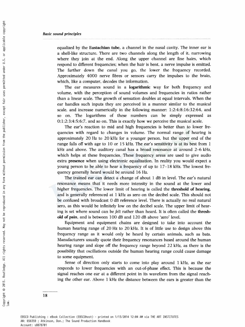
The part of the ear that senses sound is a tiny spiral structure called the cochlea. Sound enters the ear via the outer ear and auditory canal. The channel has a resonance peak of about 3-6 kHz. At the end of the auditory canal is the eardrum; this vibrates in sympathy with the incoming sound but is not too good at following low-frequency signals. Three small bones carry the vibrations from the eardrum, forming a sort of impedance-matching device, converting the acoustic energy of the air to a form more suitable for transmission through the fluid of the tiny channels of the inner ear (Figure 1.4).
The middle ear contains air, which permits the free vibration of the eardrum, and avoids excessive damping of the movement of the small bones. Air pressure is
Outer ear and auditory canal
The oval window
.--+--The ~--·• cochlea
Figure 1.4 The human ear and its component parts.
Pressure equalizing chamber
17
Copyright © 2013. Rou
tledge. All rights reserved. May not be reproduced in any form without permission from the publisher, except fair uses permitted under U.S. or applicable copyright
law.
EBSCO Publishing : eBook Collection (EBSCOhost) - printed on 1/13/2014 12:04 AM via THE ART INSTITUTESAN: 656359 ; Atkinson, Don.; The Sound Production HandbookAccount: s8878701
Basic sound principles
18
equalized by the Eustachian tube, a channel in the nasal cavity. The inner ear is a shell-like structure. There are two channels along the length of it, narrowing where they join at the end. Along the upper channel are fine hairs, which respond to different frequencies; when the hair is bent, a nerve impulse is emitted. The further down the canal you go, the lower the frequency recorded. Approximately 4000 nerve fibres or sensors carry the impulses to the brain, which, like a computer, decodes the information.
The ear measures sound in a logarithmic way for both frequency and volume, with the perception of sound volumes and frequencies in ratios rather than a linear scale. The growth of sensation doubles at equal intervals. When the ear handles such inputs they are perceived in a manner similar to the musical scale, and increase numerically in the following manner: 1:2:4:8:16:32:64, and so on. The logarithms of these numbers can be simply expressed as 0:1:2:3:4:5:6:7, and so on. This is exactly how we perceive the musical scale.
The ear's reaction to mid and high frequencies is better than to lower frequencies with regard to changes in volume. The normal range of hearing is approximately 20 Hz to 20 kHz for a younger person, but the upper end of the range falls off with age to 10 or 15 kHz. The ear's sensitivity is at its best from 1 kHz and above. The auditory canal has a broad resonance at around 2-6 kHz, which helps at these frequencies. These frequency areas are used to give audio extra presence when using electronic equalization. In reality you would expect a young person to be able to hear a frequency of up to 1 7-18 kHz. The lowest frequency generally heard would be around 16 Hz.
The trained ear can detect a change of about 1 dB in level. The ear's natural resonance means that it needs more intensity in the sound at the lower and higher frequencies. The lower limit of hearing is called the threshold of hearing, and is generally referenced at 1 kHz as zero on the decibel scale. This should not be confused with broadcast 0 dB reference level. There is actually no real natural zero, as this would be infinitely low on the decibel scale. The upper limit of hearing is set where sound can be felt rather than heard. It is often called the threshold of pain, and is between 100 dB and 120 dB above 'zero' level.
Equipment and equipment chains are designed to take into account the human hearing range of 20 Hz to 20 kHz. It is of little use to design above this frequency range as it would only be heard by certain animals, such as bats. Manufacturers usually quote their frequency resonances based around the human hearing range and slope off the frequency range beyond 22 kHz, as there is the possibility that oscillations outside the human hearing range could cause damage to some equipment.
Sense of direction only starts to come into play around 1 kHz, as the ear responds to lower frequencies with an out-of-phase effect. This is because the signal reaches one ear at a different point in its waveform from the signal reaching the other ear. Above 1 kHz the distance between the ears is greater than the
Copyright © 2013. Rou
tledge. All rights reserved. May not be reproduced in any form without permission from the publisher, except fair uses permitted under U.S. or applicable copyright
law.
EBSCO Publishing : eBook Collection (EBSCOhost) - printed on 1/13/2014 12:04 AM via THE ART INSTITUTESAN: 656359 ; Atkinson, Don.; The Sound Production HandbookAccount: s8878701

Fidelity
wavelength, so the signal heard in each ear is in phase, occurring at the same point on the signal wavelength.
The mass of the head has a shielding effect, which causes each ear to receive the signal in phase but at slightly different volume. By turning the head and equalizing the signal level we get our sense of direction. Obviously we get our sense of direction from the higher-frequency signals and their time of arrival (TOA). This effect will be discussed later in the section on the A/B stereo system (p. 163), as arrival time at the ears is the main effect that allows us to perceive sound in stereo.
SIGNAL-TO-NOISE RATIO
The signal-to-noise ratio of a system or individual piece of equipment is the ratio between peak programme and the peaks of noise. The figure is always quoted in decibels (see Chapter 2). In general terms, the higher the decibel figure the better the signal-to-noise. The general problem with all audio equipment in the past has been to maintain a good signal-to-noise relationship: equipment electronics had to be extremely well designed to keep the noise figure down to acceptable levels.
System noise on its own is not the only form of signal-to-noise ratio to consider. In the same way as hiss or noise would be annoying on the recorded or live audio signal, so would any noise that was not the noise we wished to hear, such as traffic or drills. When considering a recording made outside on a location with heavy traffic, the traffic level may be at such a ratio that it confuses the main signal, which might be a person playing a part in a drama or just making a statement to camera. These interferences to the sound we require to transmit or record are unwanted noise, which it is desirable to reduce to the minimum. The ways of dealing with these problems will be discussed later in the section on location recording (p. 114). See also the section on audio acceptability levels on p. 160.
As noise is generally additive, with all sorts of equipment in the chain creating their own form of noise, the highest possible signal-to-noise ratio must be maintained on all the components down the chain. Modern microphones have improved noise figures, as have the microphone amplifiers and the audio equipment that follow in the chain. Digital equipment, by its very design, can achieve noise figures of up to 94 dB, which is a figure at which we would not perceive any problem. Unfortunately, not all systems are digital, and the old analogue equipment still has poor noise figures. Magnetic tape adds another noise problem, as does the tape used in videotape recording, which is formulated to favour the video signal rather than the audio signal (recorded on a separate track alongside).
Electronic noise-reduction circuits such as Dolby C and Dolby A, and other similar systems, help to reduce tape noise by their own particular compression of frequency ranges during recording and expansion of these bands on replay. However, no noise-reduction system can reduce noise that is there as part of the audio signal being introduced to the mixer input circuit. Nor can a noise-reduction circuit help if the microphone itself is generating some noise.
19
Copyright © 2013. Rou
tledge. All rights reserved. May not be reproduced in any form without permission from the publisher, except fair uses permitted under U.S. or applicable copyright
law.
EBSCO Publishing : eBook Collection (EBSCOhost) - printed on 1/13/2014 12:04 AM via THE ART INSTITUTESAN: 656359 ; Atkinson, Don.; The Sound Production HandbookAccount: s8878701

Basic sound principles
In the near future it will be possible to go 100% digital, with location and studio video recorders having their own dedicated digital tracks. Further transmission of the audio signal can be handled digitally, keeping the whole process from the original to the actual transmission totally within the digital domain.
Most current high-quality microphones now have a signal-to-noise ratio of about 7 4-84 dB, so little problem will be found there. However, these are the newer microphones, and there are still plenty of the older microphones around. Most high-quality capacitor microphones, even of the older type, attain a signalto-noise ratio of 72-80 dB. The other factor to consider is the matching of microphones or any other device to a mixer input, as this also can cause noise due to microphone amplifiers working at gain levels that are too high.
THE BALANCED INPUT SYSTEM
20
As the input system normally used within broadcast work is a balanced system it would be wise to look at what the system is in practice and its advantages.
A balanced system is usually constructed with differential input amplifiers, either balanced electronically, or by using high-quality audio transformers in some equipment. The cables used within a balanced system are twin cables with a separate screen. Both the inner cables are twisted upon each other and covered by a tight braided screen. One cable is labelled +V (hot); the other is labelled -V (cold) plus the ground signal. The design of the differential input amplifiers is such that interference picked up on these wires from outside the equipment is cancelled out by the input circuit. This is because, as both wires are in close proximity, the same interference will be picked up on each wire, and balanced input amplifiers will only amplify the difference between +V (hot) and -V (cold). Any signal on both hot and cold (i.e. noise) will not be amplified. This is known as common mode rejection (CMR). Balanced inputs should always have both inputs connected or, if used as an unbalanced input source, the -V connection should be shorted to ground. A typical balanced input circuit is illustrated in Figure 1.5.
Modern audio and musical instruments often have electronically balanced outputs; these should not be shorted to ground and should be fed into a balanced input only. Usually there is a warning on such outputs. Generally, transformerbalanced inputs are preferred by the industry, possibly for standardization reasons, and the fact that a transformer offers a greater degree of isolation and rejection of radio frequency interference.
Often ground-compensated outputs are supplied on mixers. This is a very effective way to optimize noise immunity. These outputs employ ground-compensating techniques to cancel out effects of variation in ground potentials between the mixer and other equipment resulting in hum. If these types of output are fed to an unbalanced input then the -V (cold) connection must be shorted to ground at the signal's destination, not at the originating mixer end.
Copyright © 2013. Rou
tledge. All rights reserved. May not be reproduced in any form without permission from the publisher, except fair uses permitted under U.S. or applicable copyright
law.
EBSCO Publishing : eBook Collection (EBSCOhost) - printed on 1/13/2014 12:04 AM via THE ART INSTITUTESAN: 656359 ; Atkinson, Don.; The Sound Production HandbookAccount: s8878701

OV
Balanced output
Balanced input
The balanced input system
Unbalanced output
ov
Figure 1. 5 Circuit diagram of a typical balanced input system.
Polarity is particularly important in balanced systems. Just as a balanced system is highly effective in cancelling out any unwanted interference, so if two microphones were connected with the phase reversed on one of the microphones, serious degrading of the signal would occur as explained earlier. These sorts of problem are rare in normal domestic systems, with their unbalanced operation, and would only occur because of poor design and phase reversal within the equipment.
Earth loops are difficult to avoid at times, but generally can be eliminated if the earth connection is made at the source end, not both ends. An important piece of equipment to carry within a location kit is a box with an earth-lift switch, so that an earth loop can be cleared at either the transmitting end or the receiving end. It is also useful to have some sort of phase reversal within the unit, and this is normally provided in commercial direct injection boxes.
Balanced and unbalanced systems in the field
Recording audio for broadcast purposes usually entails all the units supplied being balanced, and balanced broadcast practices should always be observed. The 'outside world', however, frequently presents itself in an unbalanced form, technically speaking. It would be advisable in the field to carry the following units for interfacing to the outside world:
• A 600 n balanced-to-balanced transformer unit in a mu-metal case if possible, with an earth-lift switch.
• A direct inject box with gain switching from high-level line output to lowlevel mic input (this is needed if you are short of line level inputs on the mixer) Some mixer units' output sockets only feed outputs at mic level; also, direct feeds from public address systems can be at any level and are often unbalanced sources.
• An assortment of cable adapiors, such as jack to XLR, phono, aircraft NATO and single-pole aircraft jacks to XLR female plugs. Useful also would be 'back to back' converters for XLR plugs and sockets.
• A microphone splitter to allow a single 'front mic' to be split between your output and a public address system, or to feed the same signal to another broadcaster.
21
Copyright © 2013. Rou
tledge. All rights reserved. May not be reproduced in any form without permission from the publisher, except fair uses permitted under U.S. or applicable copyright
law.
EBSCO Publishing : eBook Collection (EBSCOhost) - printed on 1/13/2014 12:04 AM via THE ART INSTITUTESAN: 656359 ; Atkinson, Don.; The Sound Production HandbookAccount: s8878701
Basic sound principles
Unbalanced microphones
22
Using unbalanced microphones with professional equipment is usually no problem unless phantom power is being used on the channel input to which the microphone is connected. (Phantom powering is described in Chapter 3.) Unbalancing one leg can short out a phantom power supply and cause damage to the mic and the phantom supply. It is advisable to carry a 'one-to-one' transformer if you wish to get away from the phantom supply or switch away the phantom powering on the individual channel if that is possible.
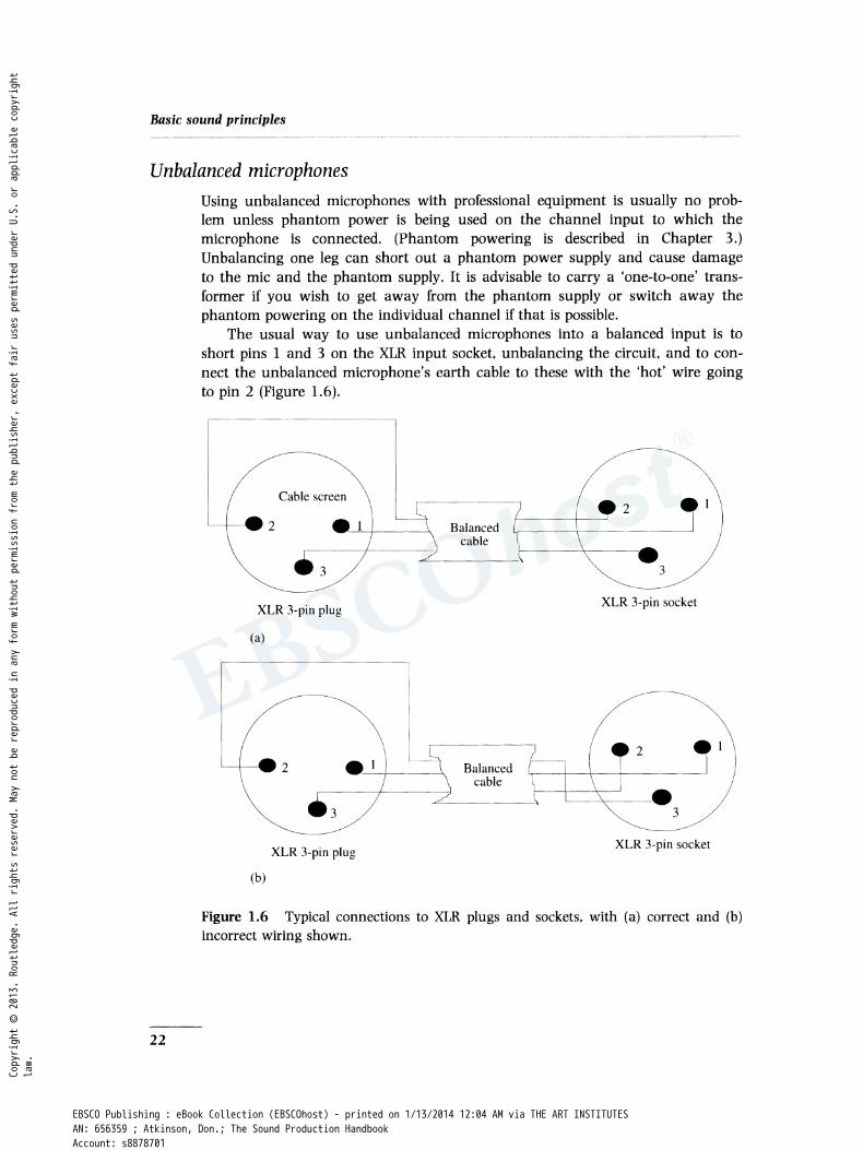
The usual way to use unbalanced microphones into a balanced input is to short pins 1 and 3 on the XLR input socket, unbalancing the circuit, and to connect the unbalanced microphone's earth cable to these with the 'hot' wire going to pin 2 (Figure 1.6).
-----------
Cable screen
XLR 3-pin plug XLR 3-pin socket
(a)
._1
XLR 3-pin plug XLR 3-pin socket
(b)
Figure 1.6 Typical connections to XLR plugs and sockets, with (a) correct and (b) incorrect wiring shown.
Copyright © 2013. Rou
tledge. All rights reserved. May not be reproduced in any form without permission from the publisher, except fair uses permitted under U.S. or applicable copyright
law.
EBSCO Publishing : eBook Collection (EBSCOhost) - printed on 1/13/2014 12:04 AM via THE ART INSTITUTESAN: 656359 ; Atkinson, Don.; The Sound Production HandbookAccount: s8878701